WO2017141414A1 - Feature data structure, control device, storage device, control method, program, and storage medium - Google Patents
Feature data structure, control device, storage device, control method, program, and storage medium Download PDFInfo
- Publication number
- WO2017141414A1 WO2017141414A1 PCT/JP2016/054806 JP2016054806W WO2017141414A1 WO 2017141414 A1 WO2017141414 A1 WO 2017141414A1 JP 2016054806 W JP2016054806 W JP 2016054806W WO 2017141414 A1 WO2017141414 A1 WO 2017141414A1
- Authority
- WO
- WIPO (PCT)
- Prior art keywords
- information
- feature
- landmark
- setting information
- unit
- Prior art date
Links
Images


Classifications
-
- G—PHYSICS
- G01—MEASURING; TESTING
- G01S—RADIO DIRECTION-FINDING; RADIO NAVIGATION; DETERMINING DISTANCE OR VELOCITY BY USE OF RADIO WAVES; LOCATING OR PRESENCE-DETECTING BY USE OF THE REFLECTION OR RERADIATION OF RADIO WAVES; ANALOGOUS ARRANGEMENTS USING OTHER WAVES
- G01S17/00—Systems using the reflection or reradiation of electromagnetic waves other than radio waves, e.g. lidar systems
- G01S17/88—Lidar systems specially adapted for specific applications
- G01S17/93—Lidar systems specially adapted for specific applications for anti-collision purposes
- G01S17/931—Lidar systems specially adapted for specific applications for anti-collision purposes of land vehicles
-
- G—PHYSICS
- G01—MEASURING; TESTING
- G01C—MEASURING DISTANCES, LEVELS OR BEARINGS; SURVEYING; NAVIGATION; GYROSCOPIC INSTRUMENTS; PHOTOGRAMMETRY OR VIDEOGRAMMETRY
- G01C21/00—Navigation; Navigational instruments not provided for in groups G01C1/00 - G01C19/00
- G01C21/26—Navigation; Navigational instruments not provided for in groups G01C1/00 - G01C19/00 specially adapted for navigation in a road network
- G01C21/28—Navigation; Navigational instruments not provided for in groups G01C1/00 - G01C19/00 specially adapted for navigation in a road network with correlation of data from several navigational instruments
-
- G—PHYSICS
- G01—MEASURING; TESTING
- G01C—MEASURING DISTANCES, LEVELS OR BEARINGS; SURVEYING; NAVIGATION; GYROSCOPIC INSTRUMENTS; PHOTOGRAMMETRY OR VIDEOGRAMMETRY
- G01C21/00—Navigation; Navigational instruments not provided for in groups G01C1/00 - G01C19/00
- G01C21/38—Electronic maps specially adapted for navigation; Updating thereof
- G01C21/3804—Creation or updating of map data
- G01C21/3807—Creation or updating of map data characterised by the type of data
- G01C21/3811—Point data, e.g. Point of Interest [POI]
-
- G—PHYSICS
- G01—MEASURING; TESTING
- G01C—MEASURING DISTANCES, LEVELS OR BEARINGS; SURVEYING; NAVIGATION; GYROSCOPIC INSTRUMENTS; PHOTOGRAMMETRY OR VIDEOGRAMMETRY
- G01C21/00—Navigation; Navigational instruments not provided for in groups G01C1/00 - G01C19/00
- G01C21/38—Electronic maps specially adapted for navigation; Updating thereof
- G01C21/3804—Creation or updating of map data
- G01C21/3833—Creation or updating of map data characterised by the source of data
- G01C21/3848—Data obtained from both position sensors and additional sensors
-
- G—PHYSICS
- G01—MEASURING; TESTING
- G01S—RADIO DIRECTION-FINDING; RADIO NAVIGATION; DETERMINING DISTANCE OR VELOCITY BY USE OF RADIO WAVES; LOCATING OR PRESENCE-DETECTING BY USE OF THE REFLECTION OR RERADIATION OF RADIO WAVES; ANALOGOUS ARRANGEMENTS USING OTHER WAVES
- G01S17/00—Systems using the reflection or reradiation of electromagnetic waves other than radio waves, e.g. lidar systems
- G01S17/02—Systems using the reflection of electromagnetic waves other than radio waves
- G01S17/06—Systems determining position data of a target
- G01S17/42—Simultaneous measurement of distance and other co-ordinates
-
- G—PHYSICS
- G01—MEASURING; TESTING
- G01S—RADIO DIRECTION-FINDING; RADIO NAVIGATION; DETERMINING DISTANCE OR VELOCITY BY USE OF RADIO WAVES; LOCATING OR PRESENCE-DETECTING BY USE OF THE REFLECTION OR RERADIATION OF RADIO WAVES; ANALOGOUS ARRANGEMENTS USING OTHER WAVES
- G01S17/00—Systems using the reflection or reradiation of electromagnetic waves other than radio waves, e.g. lidar systems
- G01S17/86—Combinations of lidar systems with systems other than lidar, radar or sonar, e.g. with direction finders
-
- G—PHYSICS
- G01—MEASURING; TESTING
- G01S—RADIO DIRECTION-FINDING; RADIO NAVIGATION; DETERMINING DISTANCE OR VELOCITY BY USE OF RADIO WAVES; LOCATING OR PRESENCE-DETECTING BY USE OF THE REFLECTION OR RERADIATION OF RADIO WAVES; ANALOGOUS ARRANGEMENTS USING OTHER WAVES
- G01S17/00—Systems using the reflection or reradiation of electromagnetic waves other than radio waves, e.g. lidar systems
- G01S17/88—Lidar systems specially adapted for specific applications
- G01S17/89—Lidar systems specially adapted for specific applications for mapping or imaging
-
- G—PHYSICS
- G01—MEASURING; TESTING
- G01S—RADIO DIRECTION-FINDING; RADIO NAVIGATION; DETERMINING DISTANCE OR VELOCITY BY USE OF RADIO WAVES; LOCATING OR PRESENCE-DETECTING BY USE OF THE REFLECTION OR RERADIATION OF RADIO WAVES; ANALOGOUS ARRANGEMENTS USING OTHER WAVES
- G01S7/00—Details of systems according to groups G01S13/00, G01S15/00, G01S17/00
- G01S7/48—Details of systems according to groups G01S13/00, G01S15/00, G01S17/00 of systems according to group G01S17/00
- G01S7/483—Details of pulse systems
- G01S7/484—Transmitters
-
- G—PHYSICS
- G01—MEASURING; TESTING
- G01S—RADIO DIRECTION-FINDING; RADIO NAVIGATION; DETERMINING DISTANCE OR VELOCITY BY USE OF RADIO WAVES; LOCATING OR PRESENCE-DETECTING BY USE OF THE REFLECTION OR RERADIATION OF RADIO WAVES; ANALOGOUS ARRANGEMENTS USING OTHER WAVES
- G01S7/00—Details of systems according to groups G01S13/00, G01S15/00, G01S17/00
- G01S7/48—Details of systems according to groups G01S13/00, G01S15/00, G01S17/00 of systems according to group G01S17/00
- G01S7/483—Details of pulse systems
- G01S7/486—Receivers
- G01S7/4865—Time delay measurement, e.g. time-of-flight measurement, time of arrival measurement or determining the exact position of a peak
-
- G—PHYSICS
- G01—MEASURING; TESTING
- G01S—RADIO DIRECTION-FINDING; RADIO NAVIGATION; DETERMINING DISTANCE OR VELOCITY BY USE OF RADIO WAVES; LOCATING OR PRESENCE-DETECTING BY USE OF THE REFLECTION OR RERADIATION OF RADIO WAVES; ANALOGOUS ARRANGEMENTS USING OTHER WAVES
- G01S7/00—Details of systems according to groups G01S13/00, G01S15/00, G01S17/00
- G01S7/48—Details of systems according to groups G01S13/00, G01S15/00, G01S17/00 of systems according to group G01S17/00
- G01S7/483—Details of pulse systems
- G01S7/486—Receivers
- G01S7/4868—Controlling received signal intensity or exposure of sensor
-
- G—PHYSICS
- G06—COMPUTING; CALCULATING OR COUNTING
- G06F—ELECTRIC DIGITAL DATA PROCESSING
- G06F16/00—Information retrieval; Database structures therefor; File system structures therefor
- G06F16/20—Information retrieval; Database structures therefor; File system structures therefor of structured data, e.g. relational data
- G06F16/29—Geographical information databases
-
- G—PHYSICS
- G09—EDUCATION; CRYPTOGRAPHY; DISPLAY; ADVERTISING; SEALS
- G09B—EDUCATIONAL OR DEMONSTRATION APPLIANCES; APPLIANCES FOR TEACHING, OR COMMUNICATING WITH, THE BLIND, DEAF OR MUTE; MODELS; PLANETARIA; GLOBES; MAPS; DIAGRAMS
- G09B29/00—Maps; Plans; Charts; Diagrams, e.g. route diagram
Definitions
- the present invention relates to a technique for detecting an object.
- Patent Document 1 in order to be able to measure a wide range from an object with a high reflectance and a nearby object to an object with a low reflectance and a far object, the transmission intensity or reception of the laser within a predetermined time width is disclosed.
- a measuring device is disclosed that dynamically changes the amplification factor, outputs a distance value where the received wave is not saturated and the intensity of the received wave is high as a distance.
- the present invention has been made in order to solve the above-described problems, for example, and has as its main purpose to detect an object efficiently and accurately.
- the invention described in claim is a feature data structure indicating a feature, and includes at least setting information in the detection device for detecting the feature by the detection device.
- the invention described in the claims is a feature data structure indicating a plurality of features, and at least a plurality of setting information in the detection device for detecting each of the plurality of features by the detection device. included.
- the invention described in the claims is a control device, and includes a first acquisition unit that acquires position information indicating a position of a moving body, and a feature that exists around the position indicated by the position information.
- a second acquisition unit that acquires setting information related to settings in the detection unit for detecting by the control unit, and a control unit that controls the detection unit based on the setting information.
- the invention described in the claims is a control method executed by the control device, and is present around a first acquisition step of acquiring position information indicating the position of the moving body and a position indicated by the position information.
- the invention described in the claims is a program executed by a computer, the first acquisition unit for acquiring position information indicating the position of the moving body, and the feature existing around the position indicated by the position information
- a second acquisition unit that acquires setting information related to the setting in the detection unit for detecting the detection unit by the detection unit, and the control unit that controls the detection unit based on the setting information.
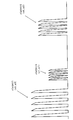
- FIG. 7 shows a waveform of the output intensity of a lidar pulse laser in one scan in the example of FIG. It is a schematic structure of the advanced map system which concerns on a modification.
- the setting information is information on a peak power of the light or a cycle of emitting the light.
- the detection device can emit light with a peak power and a light emission period corresponding to the size and reflectance of the feature to be irradiated with light, and can accurately detect the feature.
- the second acquisition unit acquires the setting information corresponding to the features present in the vicinity from a server device having a feature information database including the setting information for each feature.
- the control device can suitably acquire setting information for detecting features around the position of the moving object from the server device, and can detect the features by the detection unit.
- a storage device for storing feature information relating to a feature, wherein the feature information includes at least the detection for detecting the feature by a detection device.
- Setting information in the device is included.
- a control method executed by the control device the first acquisition step of acquiring position information indicating the position of the moving body, and the vicinity of the position indicated by the position information
- a second acquisition step of acquiring setting information related to the setting in the detection unit for detecting a feature existing in the detection unit and a control step of controlling the detection unit based on the setting information.
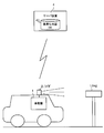
- the in-vehicle device 1 is electrically connected to the lidar 2 and performs light emission control of the lidar 2 for detecting the landmark.
- the in-vehicle device 1 transmits request information including information on its own vehicle position (also referred to as “request information D1”) to the server device 4, thereby including a response including information necessary for landmark detection.
- Information also referred to as “response information D2”
- the response information D2 includes the position information of the landmark to be detected (also referred to as “landmark position information”) and parameters related to the emission control of the light pulse of the lidar 2 for detecting the landmark to be detected by the lidar 2.
- Information also referred to as “pulse type information”.
- the vehicle-mounted device 1 controls the rider 2 based on the response information D2 received from the server device 4 and performs high-precision estimation of the vehicle position for automatic driving based on the output of the rider 2, or the server device
- the update information of the advanced map DB 43 stored in 4 is generated.
- the in-vehicle device 1 is an example of the “control device” in the present invention.
- the landmarks registered in the advanced map DB 43 include, for example, kilometer posts, 100 m posts, delineators, traffic infrastructure facilities (eg signs, direction signs, signals), utility poles, street lights, etc. that are periodically lined up on the side of the road. In addition to artificial features, natural features such as trees may be used.
- the lidar 2 emits a pulse laser in a predetermined angle range in the horizontal direction and the vertical direction, thereby discretely measuring the distance to an object existing in the outside world, and a three-dimensional point indicating the position of the object Generate group information.
- the lidar 2 includes an emitting unit that emits laser light while changing the irradiation direction, a light receiving unit that receives reflected light (scattered light) of the irradiated laser light, and a point group based on a light reception signal output from the light receiving unit. And an output unit for outputting information.
- the server device 4 stores an advanced map DB 43 including information on landmarks (also referred to as “landmark information”), and when the request information D1 is received from the on-vehicle device 1, the on-vehicle device included in the request information D1.
- the landmark information corresponding to the landmarks around the vehicle-mounted device 1 is extracted from the advanced map DB 43 based on the position information 1 and transmitted to the vehicle-mounted device 1 as response information D2.
- the landmark information includes at least landmark position information and pulse type information.
- the server device 4 is an example of the “storage device” in the present invention.
- the communication unit 11 performs data communication with the server device 4 based on the control of the control unit 15. Further, the communication unit 11 supplies the lidar 2 with information for controlling the emission of the pulse laser of the lidar 2 based on the control of the control unit 15.
- the storage unit 12 stores a program executed by the control unit 15 and information necessary for the control unit 15 to execute a predetermined process.
- the sensor unit 13 includes an internal sensor for detecting the state of the vehicle and an external sensor for recognizing the surrounding environment of the vehicle, and includes a camera 31, a GPS receiver 32, a gyro sensor 33, a speed sensor 34, and the like. Including.
- the control unit 15 generates current position information indicating the current position of the vehicle (that is, the own vehicle position) based on the output of the sensor 13.
- the input unit 14 is a button operated by the user, a touch panel, a remote controller, a voice input device, and the like
- the output unit 16 is, for example, a display or a speaker that performs output based on the control of the control unit 15.
- the control unit 15 includes a CPU that executes a program and controls the entire vehicle-mounted device 1.
- the control unit 15 transmits the request information D1 including the vehicle position information to the server device 4 through the communication unit 11 at predetermined time intervals, for example.
- the control unit 15 sends a control signal for changing the peak power or the pulse period of the pulse laser of the rider 2 based on the pulse type information included in the response information D2.
- the control unit 15 analyzes the output of the lidar 2 by a known analysis technique, and performs a surrounding environment recognition process, a vehicle position estimation process, or / and an update information generation process of the advanced map DB 43 and the like.
- the control unit 15 is an example of a “first acquisition unit”, “second acquisition unit”, “control unit” in the present invention, and a computer that executes a program in the present invention.
- FIG. 2B is a block diagram showing a functional configuration of the server device 4.
- the server device 4 mainly includes a communication unit 41, a storage unit 42, and a control unit 45. Each of these elements is connected to each other via a bus line.
- the communication unit 41 performs data communication with the in-vehicle device 1 based on the control of the control unit 45.
- the storage unit 42 stores a program executed by the control unit 45 and information necessary for the control unit 45 to execute a predetermined process.
- the storage unit 42 stores the advanced map DB 43.
- the advanced map DB 43 includes landmark information corresponding to each landmark that the in-vehicle device 1 is to be detected by the lidar 2.
- Fig. 2 (C) shows the data structure of landmark information.
- the landmark information is information generated for each landmark, and includes, for example, landmark position information, pulse type information, landmark ID, type information, and size information.
- the pulse type information may be different information for each landmark shape (size) and light reflectance, for example, as will be described later.
- the landmark information is stored in the map DB 43 in such a data structure, for example, when the position is specified by the position information (position information of the vehicle-mounted device 1) included in the request information D1, the identification is performed. It is possible to extract landmarks that exist around the specified position. Also, by referring to the landmark information of the extracted landmark, lidar setting information for detecting the landmark by the lidar 2 (in other words, setting information suitable for detection by the lidar 2).
- the landmark information may include each piece of information such as the shape of the landmark and the reflectance in addition to the above pieces of information (or instead of the above pulse type information).
- the landmark information is an example of “feature data structure” and “feature information” in the present invention
- the pulse type information is an example of “setting information” in the present invention
- the advanced map DB 43 is the present invention. This is an example of “database” in FIG.
- the landmark information includes information on the peak power and / or pulse period of the pulse laser to be emitted by the lidar 2 as setting information for detecting the landmark by the lidar 2 instead of the pulse type information. Also good.
- the server device 4 may transmit the response information D2 to the in-vehicle device 1 including information on the peak power and / or the pulse period of the pulse laser to be emitted by the lidar 2.
- the control unit 45 includes a CPU that executes a program and the like, and controls the entire server device 4.
- the control unit 45 receives the position information of the in-vehicle device 1 included in the request information D1 and each of the registered in the advanced map DB 43.
- the landmark information around the vehicle-mounted device 1 is extracted by comparing the landmark position information included in the landmark information.
- the control unit 45 transmits response information D2 including at least the landmark position information and the pulse type information of the extracted landmark information to the in-vehicle device 1 through the communication unit 41.
- the in-vehicle device 1 determines the peak power and the pulse period of the pulse laser emitted from the lidar 2 based on the pulse type information included in the response information D2 received from the server device 4.
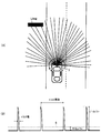
- FIG. 3A is a diagram showing the light beam of the pulse laser emitted by the lidar 2 by one scan
- FIG. 3B shows the time change of the output power of the pulse laser emitted by the lidar 2. Part of the waveform.
- the rider 2 applies a predetermined angular resolution determined by a pulse period to a predetermined angular range (about 210 ° in this example) including the forward direction of the vehicle.
- the laser is emitted.
- the in-vehicle device 1 receives the pulse type information corresponding to the landmark Ltag from the server device 4, and applies a pulse laser to the lidar 2 based on the peak power and the pulse period based on the pulse type information.
- the light is emitted.
- the peak power corresponds to the amplitude of the peak of the waveform
- the pulse period corresponds to the time interval of the peak of the waveform.
- the average power (see broken line 6) of the pulse laser shown in FIG. 3B is uniquely determined based on the peak power, the pulse width, and the pulse period, and an upper limit is defined for eye-safety. Therefore, the peak power, the pulse width, and the pulse period are set so that the average power does not violate the eye-safe condition.
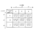
- FIG. 4 is a table showing an example of the pulse type of the pulse laser specified by the pulse type information.
- the pulse type here, pulse type A to pulse type I
- the pulse laser emitted from the lidar 2 corresponds to a combination of peak power (here, p1 to p3) and a pulse period (here, c1 to c3).
- peak power here, p1 to p3
- pulse period here, c1 to c3
- it differs depending on the reflectance and size of the landmark to be detected by the lidar 2. If the reflectance and size of a landmark can be extracted by using this table, setting information (pulse type) for detecting the landmark with a lidar can be extracted (recognized).
- the reflectance of the landmark is classified into three levels of “large”, “medium”, and “small”, and the smallest peak power “p1” for the reflectance “large”. ”, The largest peak power“ p3 ”is associated with the reflectance“ small ”, and the middle peak power“ p2 ”is associated with the reflectance“ medium ”.
- the landmark size is classified into three stages of “large”, “medium”, and “small”, and the longest pulse period “c3” is associated with the size “large”.
- the shortest pulse period “c1” is associated with the size “small”, and the intermediate pulse period “c2” is associated with the size “medium”.
- nine pulse types A to I differ in the combination of the three-stage peak power and the three-stage pulse period, respectively, depending on the combination of the three-stage reflectance and the three-stage size of the landmark. Is stipulated.
- the pulse type information indicates a combination of an appropriate peak power and pulse period determined in advance according to the reflectance and size of the target landmark. Further, the pulse type information is stored in the advanced map DB 43 as a part of the landmark information as shown in FIG. Therefore, the in-vehicle device 1 receives the response information D2 including the pulse type information from the server device 4, and sets the peak power and the pulse period of the lidar 2 based on the pulse type information, so that the landmark can be simply and highly accurate. Can be detected by the lidar 2.
- At least one of the reflectance and size of the landmark may be set in four or more stages, and more pulse types may be provided. Even in this case, as the reflectance of the landmark is smaller, a larger peak power is associated, and as the landmark size is smaller, a shorter pulse period is associated. Thereby, the lidar 2 can be set according to the reflectance and size of the landmark to be detected, and the landmark can be detected with high accuracy. Similarly, at least one of the reflectance and size of the landmark may be set in two stages.
- the data structure of the landmark information is a data structure including the pulse type information in the landmark information.
- the table shown in FIG. You may make it memorize
- the landmark information it is possible to extract the shape and reflectance of the landmark existing around the position specified by the position information (position information of the vehicle-mounted device 1) included in the request information D1. Further, by referring to the table shown in FIG. 4, the pulse type corresponding to the extracted shape and reflectance can be extracted.
- the peak power and the pulse period may be optimally set according to the relative distance between the landmark calculated from the landmark position information and the position information of the vehicle-mounted device 1 and the host vehicle. .
- “Large” has the shortest cycle
- “Small” has the longest pulse cycle
- “Middle” has The middle may be allocated, the large peak power may be allocated to “large”, the small peak power may be allocated to “small”, and the middle may be allocated to “medium”.
- FIG. 5 is a flowchart showing a processing procedure in the present embodiment.
- FIG. 5 shows a processing flow when the in-vehicle device 1 performs update information of the advanced map DB 43 based on the output of the rider 2 as a representative example.
- the in-vehicle device 1 repeatedly executes the process of the flowchart of FIG. 5 according to a predetermined cycle, for example.
- the in-vehicle device 1 acquires own vehicle position information based on the output of the sensor unit 13 (step S101).
- the vehicle-mounted device 1 transmits request information D1 including the vehicle position information acquired in step S101 to the server device 4 (step S102).
- the server device 4 receives the request information D1 from the in-vehicle device 1 (step S201). In this case, the server device 4 extracts landmark position information, pulse type information, and the like corresponding to landmarks present around the vehicle-mounted device 1 from the advanced map DB 43 (step S202). In this case, the server device 4 searches the advanced map DB 43 for landmark information having landmark position information indicating a position within a predetermined distance from the position indicated by the position information specified by the request information D1, and the searched landmark. At least landmark position information and pulse type information are extracted from the information. Then, the server device 4 transmits response information D2 including at least the landmark position information and the pulse type information extracted in step S202 to the in-vehicle device 1 (step S203).
- the in-vehicle device 1 receives the response information D2 transmitted from the server device 4 (step S103). Then, the in-vehicle device 1 performs the emission control of the lidar 2 based on the pulse type information included in the response information D2 (step S104). Note that the response when the response information D2 includes pulse type information and landmark position information corresponding to a plurality of landmarks will be described in detail in the [Multiple Landmark Detection Processing] section.
- the in-vehicle device 1 performs an analysis process on the output of the rider 2 (step S105). For example, first, the control unit 15 extracts the point cloud information of the landmark to be detected from the output of the lidar 2 to calculate the relative position of the landmark with respect to the own vehicle position. Thereafter, the control unit 15 estimates the absolute position of the landmark to be detected based on the calculated relative position and the absolute position of the host vehicle recognized based on the output of the sensor unit 13. Then, the control unit 15 transmits the estimated landmark position information and the like to the server device 4 as update information of the advanced map DB 43 (step S106).
- control unit 15 needs to update the advanced map DB 43 when the estimated landmark position and the position indicated by the landmark position information included in the response information D2 are separated by a predetermined distance or more. Only when it is determined that the transmission process of step S106 may be performed.
- the server apparatus 4 will update the advanced map DB43 based on the said update information, when the update information of the advanced map DB43 is received from the vehicle equipment 1 (step S204).
- the server device 4 can cause each vehicle equipped with the rider 2 to execute landmark measurement by the rider 2 based on uniform setting conditions suitable for each landmark. Measurement data with optimum measurement resolution and accuracy can be obtained for each landmark, and compatibility and reliability of measurement data can be improved. Therefore, the server device 4 acquires update information that is compatible with the landmark information registered in the advanced map DB 43 and is highly accurate from each vehicle traveling on the target road network, and the advanced map DB 43 is actually used. Can always be kept in line with the situation.
- the in-vehicle device 1 recognizes an emission angle at which each landmark is irradiated based on the landmark position information and the vehicle position information of each landmark to be detected, and the lidar 2 for each recognized emission angle. Switch the pulse type information to be applied to. Thereby, even if it is a case where a plurality of landmarks are detected at the same time, the vehicle-mounted device 1 drives the lidar 2 under setting conditions suitable for each landmark.
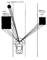
- FIG. 6 is a diagram clearly showing a pulse laser emitted by one scan when three landmarks Ltag1, Ltag2, and Ltag3 are present.
- FIG. 7 shows a waveform of the time change of the output power of the pulse laser of the lidar 2 in one scan in the example of FIG.
- the landmark Ltag1 belongs to the reflectance “small” and the size “large” in the table of FIG. 4
- the landmark Ltag2 belongs to the reflectance “large” and the size “small”
- the landmark Ltag3 is It is assumed that both the reflectance and the size are landmarks belonging to “medium”.
- the vehicle-mounted device 1 changes the peak power and the pulse period of the pulse laser that irradiates the landmarks Ltag1 to Ltag3 by time division within one pulse laser scan when the lidar 2 performs the scan.
- the in-vehicle device 1 emits a pulse laser with the peak power and the pulse period indicated by the pulse type information corresponding to the landmark Ltag1 in the emission angle range corresponding to the landmark Ltag1.
- the pulse type information corresponding to the landmark Ltag1 is pulse type I (ie, pulse Period c3, peak power p3) is shown. Therefore, the in-vehicle device 1 causes the lidar 2 to emit a pulse laser with the pulse type I (that is, the pulse period c3 and the peak power p3) in the emission angle range corresponding to the landmark Ltag1.
- the pulse type information corresponding to the landmark Ltag2 is pulse type A (that is, pulse period c1, peak power p1). Show. Therefore, the in-vehicle device 1 causes the rider 2 to emit a pulse laser with the pulse type A (that is, the pulse period c1 and the peak power p1) in the emission angle range corresponding to the landmark Ltag2. Further, since the landmark Ltag3 is a landmark having a reflectance of “medium” and a size of “medium”, the pulse type information corresponding to the landmark Ltag3 indicates the pulse type E (that is, the pulse period c2, the peak power p2). . Therefore, the vehicle-mounted device 1 causes the rider 2 to emit a pulse laser with the pulse type E (that is, the pulse period c2 and the peak power p2) in the emission angle range corresponding to the landmark Ltag3.
- the vehicle-mounted device 1 corresponds to the landmark Ltag existing in the emission angle range for each emission angle range irradiated with each landmark Ltag even when there are a plurality of landmarks Ltag.
- the rider 2 is controlled with reference to the pulse type information to be performed. Thereby, the vehicle equipment 1 can generate
- the advanced map DB 43 stored in the server device 4 includes pulse type information which is setting information for detecting a landmark by the lidar 2.
- the vehicle equipment 1 received the response information D2 including the pulse type information corresponding to the landmark around the own vehicle position by transmitting the request information D1 including the own vehicle position information to the server device 4 and received it.
- the lidar 2 is controlled based on the pulse type information.
- the in-vehicle device 1 can obtain the output result of the compatible lidar 2 with a predetermined accuracy secured without performing the process of determining the setting of the lidar 2 for detecting the landmark. it can.
- the vehicle-mounted device 1 receives the reflectance and size information of the landmark from the server device 4, and the laser pulse of the lidar 2 from these information
- the peak power and pulse period may be determined and the lidar 2 may be controlled.
- the server apparatus 4 stores in advance landmark information and size information as landmark information stored in the advanced map DB 43, and when the request information D1 is received, the landmark reflectance. And response information D2 including size information is transmitted to the in-vehicle device 1. Further, the in-vehicle device 1 stores in advance a correspondence table between the reflectance and size of landmarks as shown in FIG. 4 and the peak power and pulse period of laser pulses to be emitted.
- the vehicle-mounted device 1 When the vehicle-mounted device 1 receives the response information D2 from the server device 4, the vehicle-mounted device 1 refers to the correspondence table described above based on the reflectance and size information of the landmarks included in the response information D2, so that the rider 2 The peak power and pulse period of the laser pulse to be emitted are determined, and the lidar 2 is controlled.
- the in-vehicle device 1 may store the advanced map DB 43 in the storage unit 12 in advance, instead of the server device 4.
- FIG. 8 shows an advanced map system according to a modification.
- the in-vehicle device 1 stores the advanced map DB 43.
- the in-vehicle device 1 executes step S202 instead of the server device 4 after acquiring the vehicle position information in step S101, so that a pulse corresponding to the landmark Ltag around the vehicle position is obtained.
- Type information and the like are extracted from the advanced map DB 43.
- the vehicle equipment 1 controls the rider 2 based on the extracted pulse type information and the like.
- the in-vehicle device 1 does not need to communicate with the server device 4.
- the in-vehicle device 1 may hold a part of the advanced map DB 43 by downloading it from the server device 4.
- the advanced map DB 43 is managed for each area, and when the vehicle-mounted device 1 reaches the predetermined area for the first time, the map data corresponding to the area is received from the server device 4.
- the in-vehicle device 1 may store in advance only a landmark information database corresponding to a part of the advanced map DB 43. Even in this case, the in-vehicle device 1 does not need to exchange the request information D1 and the response information D2 with the server device 4.
- the in-vehicle device 1 may be configured separately from the vehicle position measurement device that measures the vehicle position information by the sensor unit 13 or the like, and may receive the vehicle position information from the vehicle position measurement device.
Landscapes
- Engineering & Computer Science (AREA)
- Remote Sensing (AREA)
- Physics & Mathematics (AREA)
- Radar, Positioning & Navigation (AREA)
- General Physics & Mathematics (AREA)
- Computer Networks & Wireless Communication (AREA)
- Electromagnetism (AREA)
- Theoretical Computer Science (AREA)
- Automation & Control Theory (AREA)
- Databases & Information Systems (AREA)
- Mathematical Physics (AREA)
- Business, Economics & Management (AREA)
- Educational Administration (AREA)
- Educational Technology (AREA)
- Data Mining & Analysis (AREA)
- General Engineering & Computer Science (AREA)
- Optical Radar Systems And Details Thereof (AREA)
- Traffic Control Systems (AREA)
Abstract
Description
を有することを特徴とする。 The invention described in the claims is a control method executed by the control device, and is present around a first acquisition step of acquiring position information indicating the position of the moving body and a position indicated by the position information. A second acquisition step of acquiring setting information related to the setting in the detection unit for detecting a feature by the detection unit; a control step of controlling the detection unit based on the setting information;
It is characterized by having.
として前記コンピュータを機能させることを特徴とする。 The invention described in the claims is a program executed by a computer, the first acquisition unit for acquiring position information indicating the position of the moving body, and the feature existing around the position indicated by the position information A second acquisition unit that acquires setting information related to the setting in the detection unit for detecting the detection unit by the detection unit, and the control unit that controls the detection unit based on the setting information. To do.
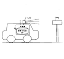
図1は、本実施例に係る高度化地図システムの概略構成である。高度化地図システムは、車両と共に移動する車載機1と、車載機1により制御されるライダ(Lidar:Light Detection and Ranging、または、Laser Illuminated Detection And Ranging)2と、高度化地図DB43を記憶するサーバ装置4とを備える。そして、高度化地図システムは、道路周辺に存在する地物(「ランドマーク」とも呼ぶ。)を検知するためのライダ2の設定をランドマークごとに画一化し、互換性のある高精度な測定データを生成する。図1では、道路沿いに設けられた看板であるランドマークLtagをライダ2により検出する例が示されている。 [Outline of advanced map system]
FIG. 1 is a schematic configuration of an advanced map system according to the present embodiment. The advanced map system includes an in-vehicle device 1 that moves together with a vehicle, a lidar (Lider: Light Illuminated Detection And Ranging) 2 controlled by the in-vehicle device 1, and a server that stores an
次に、車載機1によるライダ2のパルスレーザの出射制御について説明する。車載機1は、サーバ装置4から受信した応答情報D2に含まれるパルスタイプ情報に基づき、ライダ2に出射させるパルスレーザのピークパワー及びパルス周期を決定する。 [Lider pulse laser emission control]
Next, emission control of the pulse laser of the lidar 2 by the in-vehicle device 1 will be described. The in-vehicle device 1 determines the peak power and the pulse period of the pulse laser emitted from the lidar 2 based on the pulse type information included in the response information D2 received from the server device 4.
図5は、本実施例における処理手順を示すフローチャートである。図5は、代表例として、車載機1がライダ2の出力に基づき高度化地図DB43の更新情報を行う場合の処理フローについて示している。車載機1は、図5のフローチャートの処理を、例えば所定の周期に従い繰り返し実行する。 [Processing flow]
FIG. 5 is a flowchart showing a processing procedure in the present embodiment. FIG. 5 shows a processing flow when the in-vehicle device 1 performs update information of the
次に、複数のランドマークを同時に検出する場合について説明する。概略的には、車載機1は、検出対象の各ランドマークのランドマーク位置情報と自車位置情報とに基づき各ランドマークが照射される出射角度を認識し、認識した出射角度ごとにライダ2に適用すべきパルスタイプ情報を切り替える。これにより、車載機1は、複数のランドマークを同時に検出する場合であっても、各ランドマークに適した設定条件によりライダ2を駆動させる。 [Multiple landmark detection processing]
Next, a case where a plurality of landmarks are detected simultaneously will be described. Schematically, the in-vehicle device 1 recognizes an emission angle at which each landmark is irradiated based on the landmark position information and the vehicle position information of each landmark to be detected, and the lidar 2 for each recognized emission angle. Switch the pulse type information to be applied to. Thereby, even if it is a case where a plurality of landmarks are detected at the same time, the vehicle-mounted device 1 drives the lidar 2 under setting conditions suitable for each landmark.
次に、実施例に好適な変形例について説明する。以下の変形例は、任意に組み合わせて上述の実施例に適用してもよい。 [Modification]
Next, a modification suitable for the embodiment will be described. The following modifications may be applied in any combination to the above-described embodiments.
車載機1は、サーバ装置4から受信したパルスタイプ情報に基づきライダ2を制御する代わりに、サーバ装置4からランドマークの反射率及びサイズの情報を受信し、これらの情報からライダ2のレーザパルスのピークパワー及びパルス周期を決定し、ライダ2を制御してもよい。 (Modification 1)
Instead of controlling the lidar 2 based on the pulse type information received from the server device 4, the vehicle-mounted device 1 receives the reflectance and size information of the landmark from the server device 4, and the laser pulse of the lidar 2 from these information The peak power and pulse period may be determined and the lidar 2 may be controlled.
車載機1は、サーバ装置4に代えて、高度化地図DB43を記憶部12に予め記憶してもよい。 (Modification 2)
The in-vehicle device 1 may store the
車載機1は、センサ部13等により自車位置情報を計測する自車位置計測装置と別体に構成され、自車位置計測装置から自車位置情報を受信してもよい。 (Modification 3)
The in-vehicle device 1 may be configured separately from the vehicle position measurement device that measures the vehicle position information by the
2 ライダ
4 サーバ装置
11、41 通信部
12、42 記憶部
13 センサ部
14 入力部
15、45 制御部
16 出力部
43 高度化地図DB DESCRIPTION OF SYMBOLS 1 Vehicle equipment 2 Rider 4
Claims (11)
- 地物を示す地物データ構造であって、
少なくとも、前記地物を検知装置で検知するための前記検知装置における設定情報が含まれる地物データ構造。 A feature data structure that represents a feature,
A feature data structure including at least setting information in the detection device for detecting the feature by the detection device. - 前記検知装置は、出射方向を変えながら光を出射する出射部と前記光を受光する受光部とを有し、
前記設定情報は、前記出射部による光の出射に関するパラメータの情報である請求項1に記載の地物データ構造。 The detection device has an emission part that emits light while changing an emission direction and a light receiving part that receives the light,
The feature data structure according to claim 1, wherein the setting information is information on a parameter related to emission of light by the emission unit. - 前記設定情報は、前記光のピークパワー又は前記光を出射する周期の情報である請求項2に記載の地物データ構造。 3. The feature data structure according to claim 2, wherein the setting information is information on a peak power of the light or a cycle of emitting the light.
- 複数の地物を示す地物データ構造であって、
少なくとも、前記複数の地物のそれぞれを検知装置で検知するための前記検知装置における複数の設定情報が含まれる地物データ構造。 A feature data structure that represents multiple features,
A feature data structure including at least a plurality of setting information in the detection device for detecting each of the plurality of features by the detection device. - 移動体の位置を示す位置情報を取得する第1取得部と、
前記位置情報によって示される位置の周辺に存在する地物を検知部によって検知するための前記検知部における設定に関する設定情報を取得する第2取得部と、
前記設定情報に基づいて、前記検知部を制御する制御部と、
を備える制御装置。 A first acquisition unit that acquires position information indicating the position of the moving object;
A second acquisition unit that acquires setting information related to settings in the detection unit for detecting a feature existing around the position indicated by the position information by the detection unit;
A control unit for controlling the detection unit based on the setting information;
A control device comprising: - 前記第2取得部は、地物ごとに前記設定情報を含む地物情報のデータベースを有するサーバ装置から、前記周辺に存在する地物に対応する前記設定情報を取得する請求項5に記載の制御装置。 The control according to claim 5, wherein the second acquisition unit acquires the setting information corresponding to a feature existing in the vicinity from a server device having a feature information database including the setting information for each feature. apparatus.
- 前記検知装置は、出射方向を変えながら光を出射し、
前記地物情報には、地物ごとの位置情報が含まれ、
前記第2取得部は、前記設定情報と共に、前記地物の位置情報を取得し、
前記制御部は、前記検知部により検知すべき地物が複数存在する場合、前記地物の各々の位置情報と、前記移動体の位置情報とに基づき、前記地物の各々が存在する前記光の出射方向を特定し、特定した出射方向ごとに前記検知部に適用すべき前記設定情報を切り替える請求項5または6に記載の制御装置。 The detection device emits light while changing the emission direction,
The feature information includes position information for each feature,
The second acquisition unit acquires position information of the feature together with the setting information,
When there are a plurality of features to be detected by the detection unit, the control unit is configured to detect the light in which each of the features exists based on the position information of each of the features and the position information of the moving body. The control device according to claim 5 or 6, wherein the emission direction is specified, and the setting information to be applied to the detection unit is switched for each specified emission direction. - 地物に関する地物情報を記憶する記憶装置であって、
前記地物情報には、少なくとも、前記地物を検知装置で検知するための前記検知装置における設定情報が含まれる記憶装置。 A storage device for storing feature information about a feature,
The storage device in which the feature information includes at least setting information in the detection device for detecting the feature by a detection device. - 制御装置が実行する制御方法であって、
移動体の位置を示す位置情報を取得する第1取得工程と、
前記位置情報によって示される位置の周辺に存在する地物を検知部によって検知するための前記検知部における設定に関する設定情報を取得する第2取得工程と、
前記設定情報に基づいて、前記検知部を制御する制御工程と、
を有する制御方法。 A control method executed by a control device,
A first acquisition step of acquiring position information indicating the position of the moving body;
A second acquisition step of acquiring setting information related to the setting in the detection unit for detecting by the detection unit a feature existing around the position indicated by the position information;
A control step for controlling the detection unit based on the setting information;
A control method. - コンピュータが実行するプログラムであって、
移動体の位置を示す位置情報を取得する第1取得部と、
前記位置情報によって示される位置の周辺に存在する地物を検知部によって検知するための前記検知部における設定に関する設定情報を取得する第2取得部と、
前記設定情報に基づいて、前記検知部を制御する制御部
として前記コンピュータを機能させるプログラム。 A program executed by a computer,
A first acquisition unit that acquires position information indicating the position of the moving object;
A second acquisition unit that acquires setting information related to settings in the detection unit for detecting a feature existing around the position indicated by the position information by the detection unit;
A program that causes the computer to function as a control unit that controls the detection unit based on the setting information. - 請求項10に記載のプログラムを記憶したことを特徴とする記憶媒体。 A storage medium storing the program according to claim 10.
Priority Applications (5)
| Application Number | Priority Date | Filing Date | Title |
|---|---|---|---|
| JP2017567906A JPWO2017141414A1 (en) | 2016-02-19 | 2016-02-19 | Feature data structure, control device, storage device, control method, program, and storage medium |
| EP16890555.2A EP3418686A4 (en) | 2016-02-19 | 2016-02-19 | Feature data structure, control device, storage device, control method, program, and storage medium |
| PCT/JP2016/054806 WO2017141414A1 (en) | 2016-02-19 | 2016-02-19 | Feature data structure, control device, storage device, control method, program, and storage medium |
| US15/999,274 US11971487B2 (en) | 2016-02-19 | 2016-02-19 | Feature data structure, control device, storage device, control method, program and storage medium |
| CN201680081957.0A CN108700415A (en) | 2016-02-19 | 2016-02-19 | Atural object data structure, control device, storage device, control method, program and storage medium |
Applications Claiming Priority (1)
| Application Number | Priority Date | Filing Date | Title |
|---|---|---|---|
| PCT/JP2016/054806 WO2017141414A1 (en) | 2016-02-19 | 2016-02-19 | Feature data structure, control device, storage device, control method, program, and storage medium |
Publications (1)
| Publication Number | Publication Date |
|---|---|
| WO2017141414A1 true WO2017141414A1 (en) | 2017-08-24 |
Family
ID=59625712
Family Applications (1)
| Application Number | Title | Priority Date | Filing Date |
|---|---|---|---|
| PCT/JP2016/054806 WO2017141414A1 (en) | 2016-02-19 | 2016-02-19 | Feature data structure, control device, storage device, control method, program, and storage medium |
Country Status (5)
| Country | Link |
|---|---|
| US (1) | US11971487B2 (en) |
| EP (1) | EP3418686A4 (en) |
| JP (1) | JPWO2017141414A1 (en) |
| CN (1) | CN108700415A (en) |
| WO (1) | WO2017141414A1 (en) |
Cited By (4)
| Publication number | Priority date | Publication date | Assignee | Title |
|---|---|---|---|---|
| WO2019064741A1 (en) * | 2017-09-27 | 2019-04-04 | 日本電産株式会社 | Distance measurement device and moving body |
| CN111033303A (en) * | 2017-09-27 | 2020-04-17 | 日本电产株式会社 | Distance measuring device and moving object |
| WO2020166424A1 (en) * | 2019-02-15 | 2020-08-20 | 日本電信電話株式会社 | Position coordinate derivation device, position coordinate derivation method, position coordinate derivation program, and system |
| JP2020535058A (en) * | 2017-09-25 | 2020-12-03 | ロベルト・ボッシュ・ゲゼルシャフト・ミト・ベシュレンクテル・ハフツングRobert Bosch Gmbh | Methods and equipment for determining precision positions and driving self-driving vehicles |
Families Citing this family (7)
| Publication number | Priority date | Publication date | Assignee | Title |
|---|---|---|---|---|
| DE102016204805A1 (en) * | 2016-03-23 | 2017-09-28 | Bayerische Motoren Werke Aktiengesellschaft | Method and devices for providing data for a driver assistance system of a motor vehicle |
| PH12019050076A1 (en) * | 2019-05-06 | 2020-12-02 | Samsung Electronics Co Ltd | Enhancing device geolocation using 3d map data |
| US11754715B2 (en) * | 2019-07-11 | 2023-09-12 | Baidu Usa Llc | Point cloud format optimized for LiDAR data storage based on device property |
| CN110599853B (en) * | 2019-08-05 | 2022-07-05 | 深圳华桥智能设备科技有限公司 | Intelligent teaching system and method for driving school |
| US11675075B2 (en) * | 2019-10-15 | 2023-06-13 | Beijing Voyager Technology Co., Ltd. | Dynamic laser power control in light detection and ranging (LiDAR) systems |
| CN112698305B (en) * | 2020-12-11 | 2023-09-22 | 上海禾赛科技有限公司 | Laser radar communication method and laser radar communication system |
| US11859994B1 (en) * | 2021-02-18 | 2024-01-02 | Aurora Innovation, Inc. | Landmark-based localization methods and architectures for an autonomous vehicle |
Citations (5)
| Publication number | Priority date | Publication date | Assignee | Title |
|---|---|---|---|---|
| JP2005156261A (en) * | 2003-11-21 | 2005-06-16 | Matsushita Electric Works Ltd | Laser range finder |
| JP2007322138A (en) * | 2006-05-30 | 2007-12-13 | Toyota Motor Corp | Moving device, and own position estimation method for moving device |
| JP2010170449A (en) * | 2009-01-26 | 2010-08-05 | Calsonic Kansei Corp | Device and method for creating range image data for vehicle |
| JP2010271166A (en) * | 2009-05-21 | 2010-12-02 | Toyota Motor Corp | Obstacle detection device |
| JP2012141233A (en) * | 2011-01-04 | 2012-07-26 | Nikon Corp | Detector |
Family Cites Families (21)
| Publication number | Priority date | Publication date | Assignee | Title |
|---|---|---|---|---|
| US5170352A (en) * | 1990-05-07 | 1992-12-08 | Fmc Corporation | Multi-purpose autonomous vehicle with path plotting |
| JP3448946B2 (en) | 1994-03-11 | 2003-09-22 | 日産自動車株式会社 | Vehicle periphery monitoring device |
| JP2003069505A (en) | 2001-08-29 | 2003-03-07 | Allied Tereshisu Kk | Wireless optical communication apparatus and laser light adjustment method |
| US20030043436A1 (en) | 2001-08-29 | 2003-03-06 | Takumi Nagai | Optical wireless communication device, laser light adjustment method, optical wireless communication system, management apparatus and a computer-readable medium storing a management program |
| JP5075331B2 (en) * | 2005-09-30 | 2012-11-21 | アイシン・エィ・ダブリュ株式会社 | Map database generation system |
| JP5190664B2 (en) | 2007-04-25 | 2013-04-24 | 株式会社Ihi | Ranging method of laser radar device |
| EP2181415A2 (en) * | 2007-08-28 | 2010-05-05 | Valeo Schalter und Sensoren GmbH | Method and system for evaluating brightness values in sensor images of image-evaluating adaptive cruise control systems, especially with respect to day/night distinction |
| JP5256464B2 (en) * | 2008-03-21 | 2013-08-07 | アクリーグ株式会社 | Image top feature measurement method, display method, and measurement apparatus |
| US20090273770A1 (en) * | 2008-04-30 | 2009-11-05 | Honeywell International Inc. | Systems and methods for safe laser imaging, detection and ranging (lidar) operation |
| JP2013113684A (en) | 2011-11-28 | 2013-06-10 | Fujitsu Ltd | Distance measuring apparatus |
| US9383753B1 (en) * | 2012-09-26 | 2016-07-05 | Google Inc. | Wide-view LIDAR with areas of special attention |
| US9121703B1 (en) * | 2013-06-13 | 2015-09-01 | Google Inc. | Methods and systems for controlling operation of a laser device |
| JP5991492B2 (en) * | 2013-11-13 | 2016-09-14 | 株式会社パスコ | Data analysis apparatus, data analysis method, and program |
| DE112015002096T5 (en) * | 2014-05-02 | 2017-03-02 | Fujifilm Corporation | Distance measuring device, distance measuring method and distance measuring program |
| CN111351495B (en) * | 2015-02-10 | 2024-05-28 | 御眼视觉技术有限公司 | Server system, method, and machine-readable medium |
| US9589355B2 (en) * | 2015-03-16 | 2017-03-07 | Here Global B.V. | Guided geometry extraction for localization of a device |
| CN104794506B (en) * | 2015-04-14 | 2017-11-14 | 天津七一二通信广播股份有限公司 | It is a kind of using laser ranging can adjust automatically transmission power internet-of-things terminal |
| CN105093925B (en) * | 2015-07-15 | 2020-11-03 | 山东理工大学 | Airborne laser radar parameter real-time adaptive adjustment method based on detected terrain characteristics |
| JP6380274B2 (en) * | 2015-07-28 | 2018-08-29 | トヨタ自動車株式会社 | Navigation device for autonomous vehicles |
| CN115685149A (en) * | 2015-10-06 | 2023-02-03 | 日本先锋公司 | Light control device, control method, and storage medium |
| US9818304B2 (en) * | 2015-10-28 | 2017-11-14 | Here Global B.V. | Method and apparatus for representing an aerial delivery path |
-
2016
- 2016-02-19 CN CN201680081957.0A patent/CN108700415A/en active Pending
- 2016-02-19 JP JP2017567906A patent/JPWO2017141414A1/en active Pending
- 2016-02-19 US US15/999,274 patent/US11971487B2/en active Active
- 2016-02-19 EP EP16890555.2A patent/EP3418686A4/en active Pending
- 2016-02-19 WO PCT/JP2016/054806 patent/WO2017141414A1/en active Application Filing
Patent Citations (5)
| Publication number | Priority date | Publication date | Assignee | Title |
|---|---|---|---|---|
| JP2005156261A (en) * | 2003-11-21 | 2005-06-16 | Matsushita Electric Works Ltd | Laser range finder |
| JP2007322138A (en) * | 2006-05-30 | 2007-12-13 | Toyota Motor Corp | Moving device, and own position estimation method for moving device |
| JP2010170449A (en) * | 2009-01-26 | 2010-08-05 | Calsonic Kansei Corp | Device and method for creating range image data for vehicle |
| JP2010271166A (en) * | 2009-05-21 | 2010-12-02 | Toyota Motor Corp | Obstacle detection device |
| JP2012141233A (en) * | 2011-01-04 | 2012-07-26 | Nikon Corp | Detector |
Non-Patent Citations (1)
| Title |
|---|
| See also references of EP3418686A4 * |
Cited By (8)
| Publication number | Priority date | Publication date | Assignee | Title |
|---|---|---|---|---|
| JP2020535058A (en) * | 2017-09-25 | 2020-12-03 | ロベルト・ボッシュ・ゲゼルシャフト・ミト・ベシュレンクテル・ハフツングRobert Bosch Gmbh | Methods and equipment for determining precision positions and driving self-driving vehicles |
| JP7000562B2 (en) | 2017-09-25 | 2022-01-19 | ロベルト・ボッシュ・ゲゼルシャフト・ミト・ベシュレンクテル・ハフツング | Methods and equipment for determining precision positions and driving self-driving vehicles |
| US11435191B2 (en) | 2017-09-25 | 2022-09-06 | Robert Bosch Gmbh | Method and device for determining a highly precise position and for operating an automated vehicle |
| WO2019064741A1 (en) * | 2017-09-27 | 2019-04-04 | 日本電産株式会社 | Distance measurement device and moving body |
| CN111033303A (en) * | 2017-09-27 | 2020-04-17 | 日本电产株式会社 | Distance measuring device and moving object |
| WO2020166424A1 (en) * | 2019-02-15 | 2020-08-20 | 日本電信電話株式会社 | Position coordinate derivation device, position coordinate derivation method, position coordinate derivation program, and system |
| JP2020134220A (en) * | 2019-02-15 | 2020-08-31 | 日本電信電話株式会社 | Position coordinate derivation device, position coordinate derivation method, position coordinate derivation program, and system |
| JP7159900B2 (en) | 2019-02-15 | 2022-10-25 | 日本電信電話株式会社 | Position Coordinate Derivation Device, Position Coordinate Derivation Method, Position Coordinate Derivation Program and System |
Also Published As
| Publication number | Publication date |
|---|---|
| JPWO2017141414A1 (en) | 2018-11-29 |
| EP3418686A1 (en) | 2018-12-26 |
| CN108700415A (en) | 2018-10-23 |
| US20190041523A1 (en) | 2019-02-07 |
| US11971487B2 (en) | 2024-04-30 |
| EP3418686A4 (en) | 2019-10-23 |
Similar Documents
| Publication | Publication Date | Title |
|---|---|---|
| WO2017141414A1 (en) | Feature data structure, control device, storage device, control method, program, and storage medium | |
| US10965099B2 (en) | Light control device, control method, program and storage medium | |
| WO2017208396A1 (en) | Feature data structure, storage medium, information processing device, and detection device | |
| EP3460779A1 (en) | Information output device, terminal device, control method, program, and storage medium | |
| US11372090B2 (en) | Light detection and range (LIDAR) device with SPAD and APD sensors for autonomous driving vehicles | |
| JP2023052460A (en) | Detection device, control method, and program | |
| WO2018058947A1 (en) | Handheld blind guiding device | |
| JP2021182009A (en) | Light control device, control method, program and storage medium | |
| WO2018180245A1 (en) | Output device, control method, program, and storage medium | |
| JP2019100853A (en) | Control device, detection device, control method, program, and storage medium | |
| JP7038694B2 (en) | On-board unit, server device, and control method | |
| US20200191569A1 (en) | Geodetic stake-out system | |
| JP2011220766A (en) | Object recognition device | |
| KR20200083684A (en) | Precise Positioning System and Traveling Guidance System and Method for Autonomous Guided Vehicle using the Precise Positioning System | |
| KR102385907B1 (en) | Method And Apparatus for Autonomous Vehicle Navigation System | |
| JP7324925B2 (en) | LIGHT CONTROL DEVICE, CONTROL METHOD, PROGRAM AND STORAGE MEDIUM | |
| US20240036175A1 (en) | Single photon detection based light detection and range (lidar) for autonomous driving vehicles | |
| US20220404500A1 (en) | Online lidar intensity normalization | |
| CN205541022U (en) | A high heavy laser emission device frequently for guest flow statistics | |
| JP2020073893A (en) | Local product data structure, storage medium, information processing apparatus, and detection apparatus | |
| KR101464122B1 (en) | Laser distance sensor for platform screen door |
Legal Events
| Date | Code | Title | Description |
|---|---|---|---|
| 121 | Ep: the epo has been informed by wipo that ep was designated in this application |
Ref document number: 16890555 Country of ref document: EP Kind code of ref document: A1 |
|
| WWE | Wipo information: entry into national phase |
Ref document number: 2017567906 Country of ref document: JP |
|
| NENP | Non-entry into the national phase |
Ref country code: DE |
|
| WWE | Wipo information: entry into national phase |
Ref document number: 2016890555 Country of ref document: EP |
|
| ENP | Entry into the national phase |
Ref document number: 2016890555 Country of ref document: EP Effective date: 20180919 |