WO2017141323A1 - Energy surgery device - Google Patents
Energy surgery device Download PDFInfo
- Publication number
- WO2017141323A1 WO2017141323A1 PCT/JP2016/054309 JP2016054309W WO2017141323A1 WO 2017141323 A1 WO2017141323 A1 WO 2017141323A1 JP 2016054309 W JP2016054309 W JP 2016054309W WO 2017141323 A1 WO2017141323 A1 WO 2017141323A1
- Authority
- WO
- WIPO (PCT)
- Prior art keywords
- blood vessel
- gripping
- gripping piece
- piece
- wall thickness
- Prior art date
Links
Images


Classifications
-
- A—HUMAN NECESSITIES
- A61—MEDICAL OR VETERINARY SCIENCE; HYGIENE
- A61B—DIAGNOSIS; SURGERY; IDENTIFICATION
- A61B17/00—Surgical instruments, devices or methods, e.g. tourniquets
- A61B17/32—Surgical cutting instruments
- A61B17/320068—Surgical cutting instruments using mechanical vibrations, e.g. ultrasonic
- A61B17/320092—Surgical cutting instruments using mechanical vibrations, e.g. ultrasonic with additional movable means for clamping or cutting tissue, e.g. with a pivoting jaw
-
- A—HUMAN NECESSITIES
- A61—MEDICAL OR VETERINARY SCIENCE; HYGIENE
- A61B—DIAGNOSIS; SURGERY; IDENTIFICATION
- A61B18/00—Surgical instruments, devices or methods for transferring non-mechanical forms of energy to or from the body
- A61B18/04—Surgical instruments, devices or methods for transferring non-mechanical forms of energy to or from the body by heating
- A61B18/12—Surgical instruments, devices or methods for transferring non-mechanical forms of energy to or from the body by heating by passing a current through the tissue to be heated, e.g. high-frequency current
- A61B18/14—Probes or electrodes therefor
- A61B18/1442—Probes having pivoting end effectors, e.g. forceps
-
- A—HUMAN NECESSITIES
- A61—MEDICAL OR VETERINARY SCIENCE; HYGIENE
- A61B—DIAGNOSIS; SURGERY; IDENTIFICATION
- A61B17/00—Surgical instruments, devices or methods, e.g. tourniquets
-
- A—HUMAN NECESSITIES
- A61—MEDICAL OR VETERINARY SCIENCE; HYGIENE
- A61B—DIAGNOSIS; SURGERY; IDENTIFICATION
- A61B18/00—Surgical instruments, devices or methods for transferring non-mechanical forms of energy to or from the body
-
- A—HUMAN NECESSITIES
- A61—MEDICAL OR VETERINARY SCIENCE; HYGIENE
- A61B—DIAGNOSIS; SURGERY; IDENTIFICATION
- A61B18/00—Surgical instruments, devices or methods for transferring non-mechanical forms of energy to or from the body
- A61B18/04—Surgical instruments, devices or methods for transferring non-mechanical forms of energy to or from the body by heating
- A61B18/12—Surgical instruments, devices or methods for transferring non-mechanical forms of energy to or from the body by heating by passing a current through the tissue to be heated, e.g. high-frequency current
- A61B18/14—Probes or electrodes therefor
- A61B18/1442—Probes having pivoting end effectors, e.g. forceps
- A61B18/1445—Probes having pivoting end effectors, e.g. forceps at the distal end of a shaft, e.g. forceps or scissors at the end of a rigid rod
-
- A—HUMAN NECESSITIES
- A61—MEDICAL OR VETERINARY SCIENCE; HYGIENE
- A61B—DIAGNOSIS; SURGERY; IDENTIFICATION
- A61B17/00—Surgical instruments, devices or methods, e.g. tourniquets
- A61B2017/00017—Electrical control of surgical instruments
- A61B2017/00022—Sensing or detecting at the treatment site
- A61B2017/00026—Conductivity or impedance, e.g. of tissue
-
- A—HUMAN NECESSITIES
- A61—MEDICAL OR VETERINARY SCIENCE; HYGIENE
- A61B—DIAGNOSIS; SURGERY; IDENTIFICATION
- A61B17/00—Surgical instruments, devices or methods, e.g. tourniquets
- A61B2017/00017—Electrical control of surgical instruments
- A61B2017/00022—Sensing or detecting at the treatment site
- A61B2017/00057—Light
-
- A—HUMAN NECESSITIES
- A61—MEDICAL OR VETERINARY SCIENCE; HYGIENE
- A61B—DIAGNOSIS; SURGERY; IDENTIFICATION
- A61B17/00—Surgical instruments, devices or methods, e.g. tourniquets
- A61B2017/00367—Details of actuation of instruments, e.g. relations between pushing buttons, or the like, and activation of the tool, working tip, or the like
- A61B2017/00398—Details of actuation of instruments, e.g. relations between pushing buttons, or the like, and activation of the tool, working tip, or the like using powered actuators, e.g. stepper motors, solenoids
-
- A—HUMAN NECESSITIES
- A61—MEDICAL OR VETERINARY SCIENCE; HYGIENE
- A61B—DIAGNOSIS; SURGERY; IDENTIFICATION
- A61B17/00—Surgical instruments, devices or methods, e.g. tourniquets
- A61B17/28—Surgical forceps
- A61B17/29—Forceps for use in minimally invasive surgery
- A61B2017/2926—Details of heads or jaws
- A61B2017/2932—Transmission of forces to jaw members
- A61B2017/2938—Independently actuatable jaw members, e.g. two actuating rods
-
- A—HUMAN NECESSITIES
- A61—MEDICAL OR VETERINARY SCIENCE; HYGIENE
- A61B—DIAGNOSIS; SURGERY; IDENTIFICATION
- A61B18/00—Surgical instruments, devices or methods for transferring non-mechanical forms of energy to or from the body
- A61B2018/00315—Surgical instruments, devices or methods for transferring non-mechanical forms of energy to or from the body for treatment of particular body parts
- A61B2018/00345—Vascular system
- A61B2018/00404—Blood vessels other than those in or around the heart
- A61B2018/00428—Severing
-
- A—HUMAN NECESSITIES
- A61—MEDICAL OR VETERINARY SCIENCE; HYGIENE
- A61B—DIAGNOSIS; SURGERY; IDENTIFICATION
- A61B18/00—Surgical instruments, devices or methods for transferring non-mechanical forms of energy to or from the body
- A61B2018/00571—Surgical instruments, devices or methods for transferring non-mechanical forms of energy to or from the body for achieving a particular surgical effect
- A61B2018/00589—Coagulation
-
- A—HUMAN NECESSITIES
- A61—MEDICAL OR VETERINARY SCIENCE; HYGIENE
- A61B—DIAGNOSIS; SURGERY; IDENTIFICATION
- A61B18/00—Surgical instruments, devices or methods for transferring non-mechanical forms of energy to or from the body
- A61B2018/00571—Surgical instruments, devices or methods for transferring non-mechanical forms of energy to or from the body for achieving a particular surgical effect
- A61B2018/00601—Cutting
-
- A—HUMAN NECESSITIES
- A61—MEDICAL OR VETERINARY SCIENCE; HYGIENE
- A61B—DIAGNOSIS; SURGERY; IDENTIFICATION
- A61B18/00—Surgical instruments, devices or methods for transferring non-mechanical forms of energy to or from the body
- A61B2018/00571—Surgical instruments, devices or methods for transferring non-mechanical forms of energy to or from the body for achieving a particular surgical effect
- A61B2018/00607—Coagulation and cutting with the same instrument
-
- A—HUMAN NECESSITIES
- A61—MEDICAL OR VETERINARY SCIENCE; HYGIENE
- A61B—DIAGNOSIS; SURGERY; IDENTIFICATION
- A61B18/00—Surgical instruments, devices or methods for transferring non-mechanical forms of energy to or from the body
- A61B2018/00571—Surgical instruments, devices or methods for transferring non-mechanical forms of energy to or from the body for achieving a particular surgical effect
- A61B2018/0063—Sealing
-
- A—HUMAN NECESSITIES
- A61—MEDICAL OR VETERINARY SCIENCE; HYGIENE
- A61B—DIAGNOSIS; SURGERY; IDENTIFICATION
- A61B90/00—Instruments, implements or accessories specially adapted for surgery or diagnosis and not covered by any of the groups A61B1/00 - A61B50/00, e.g. for luxation treatment or for protecting wound edges
- A61B90/03—Automatic limiting or abutting means, e.g. for safety
- A61B2090/032—Automatic limiting or abutting means, e.g. for safety pressure limiting, e.g. hydrostatic
-
- A—HUMAN NECESSITIES
- A61—MEDICAL OR VETERINARY SCIENCE; HYGIENE
- A61B—DIAGNOSIS; SURGERY; IDENTIFICATION
- A61B90/00—Instruments, implements or accessories specially adapted for surgery or diagnosis and not covered by any of the groups A61B1/00 - A61B50/00, e.g. for luxation treatment or for protecting wound edges
- A61B90/03—Automatic limiting or abutting means, e.g. for safety
- A61B2090/033—Abutting means, stops, e.g. abutting on tissue or skin
- A61B2090/034—Abutting means, stops, e.g. abutting on tissue or skin abutting on parts of the device itself
-
- A—HUMAN NECESSITIES
- A61—MEDICAL OR VETERINARY SCIENCE; HYGIENE
- A61B—DIAGNOSIS; SURGERY; IDENTIFICATION
- A61B90/00—Instruments, implements or accessories specially adapted for surgery or diagnosis and not covered by any of the groups A61B1/00 - A61B50/00, e.g. for luxation treatment or for protecting wound edges
- A61B90/06—Measuring instruments not otherwise provided for
- A61B2090/061—Measuring instruments not otherwise provided for for measuring dimensions, e.g. length
-
- A—HUMAN NECESSITIES
- A61—MEDICAL OR VETERINARY SCIENCE; HYGIENE
- A61B—DIAGNOSIS; SURGERY; IDENTIFICATION
- A61B90/00—Instruments, implements or accessories specially adapted for surgery or diagnosis and not covered by any of the groups A61B1/00 - A61B50/00, e.g. for luxation treatment or for protecting wound edges
- A61B90/06—Measuring instruments not otherwise provided for
- A61B2090/064—Measuring instruments not otherwise provided for for measuring force, pressure or mechanical tension
- A61B2090/065—Measuring instruments not otherwise provided for for measuring force, pressure or mechanical tension for measuring contact or contact pressure
Definitions
- the present invention relates to an energy surgical device that grasps a treatment target such as a living tissue between a pair of grasping pieces and performs treatment using treatment energy such as ultrasonic vibration and high-frequency current.
- Patent Document 1 discloses an energy surgical device that can seal a treatment target by gripping a treatment target such as a living tissue between a pair of gripping pieces and applying treatment energy to the gripped treatment target. ing.
- the blood vessel to be treated may have a different wall thickness with respect to each other depending on the position and type of the blood vessel.
- a treatment for sealing (coagulating) blood vessels having different wall thicknesses with respect to each other may be performed using an energy surgical device similar to that of Patent Document 1. At this time, if each blood vessel is gripped with the same gripping force, the sealing performance of the blood vessel may be affected.
- the present invention has been made to solve the above-mentioned problems, and an object of the present invention is to provide an energy surgical device that can exhibit appropriate treatment performance even when the wall thickness of the blood vessel is different. .
- an energy surgical instrument can be opened and closed between a first gripping piece and the first gripping piece. Is closed, provided on at least one of the first gripping piece and the second gripping piece, the second gripping piece capable of gripping a blood vessel with the first gripping piece, An energy applying unit that treats the blood vessel by applying treatment energy to the blood vessel gripped between the gripping piece and the second gripping piece, and a setting unit that sets information on the wall thickness of the blood vessel When the wall thickness set by the setting unit is larger than a predetermined thickness, the gripping force for gripping the blood vessel between the first gripping piece and the second gripping piece is When the wall thickness set by the setting unit is equal to or less than a predetermined thickness , And a gripping force adjusting unit for adjusting the gripping force to the second gripping force smaller than the first holding force.
- FIG. 1 is a schematic view showing an appearance of an energy surgical device according to the first embodiment.
- FIG. 2 is a block diagram schematically showing an operation configuration and a control configuration of the energy surgical device according to the first embodiment.
- FIG. 3 is a schematic diagram illustrating an internal configuration of the housing according to the first embodiment.
- FIG. 4 is a schematic view showing the internal configuration of the housing according to the first modification.
- FIG. 5 is a schematic view showing the inside of the sheath and the configuration of the end effector according to the second modification.
- FIG. 6 is a cross-sectional view schematically showing an end effector according to a third modification in a cross section substantially perpendicular to the longitudinal axis.
- FIG. 1 is a schematic view showing an appearance of an energy surgical device according to the first embodiment.
- FIG. 2 is a block diagram schematically showing an operation configuration and a control configuration of the energy surgical device according to the first embodiment.
- FIG. 3 is a schematic diagram illustrating an internal configuration of the housing according to the first
- FIG. 7 is a schematic diagram illustrating a state where a blood vessel is gripped by the end effector according to the first embodiment.
- FIG. 8 is a schematic view schematically showing the configuration of the end effector according to the first embodiment.
- FIG. 9 is a schematic diagram illustrating a state where a blood vessel having a wall thickness larger than a predetermined thickness is gripped by the end effector according to the first embodiment.
- FIG. 10 is a schematic view showing a state where a blood vessel having a wall thickness smaller than a predetermined thickness is gripped by the end effector according to the first embodiment.
- FIG. 11 is a schematic diagram illustrating a state where a blood vessel having a wall thickness larger than a predetermined thickness is gripped by an end effector according to a fourth modification.
- FIG. 12 is a schematic view showing a state where a blood vessel thinner than a predetermined wall thickness is gripped by the end effector according to the fourth modification.
- FIG. 13 is a schematic view schematically showing a configuration of an end effector according to a fifth modification.
- FIG. 14 is a schematic diagram schematically showing a configuration of an end effector according to a sixth modification.
- FIG. 15 is a schematic view schematically showing a configuration of an end effector according to a seventh modification.
- FIG. 16 is a schematic diagram schematically showing the configuration of the end effector according to the eighth modification.
- FIG. 17 is a schematic diagram showing the configuration of the heart and its vicinity.
- FIG. 18 is a schematic diagram illustrating a state where the blood vessel is gripped with the first gripping force by the end effector according to the first embodiment.
- FIG. 19 is a schematic diagram illustrating a state where the blood vessel is gripped with the second gripping force by the end effector according to the first embodiment.
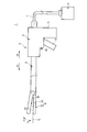
- FIG. 1 is an external view of an energy surgical device (treatment system) 1 according to the first embodiment.
- the energy surgical device 1 includes an energy treatment tool 2 and an energy control device 3.
- the energy treatment device 2 has a longitudinal axis C.
- one side in the direction along the longitudinal axis C is defined as the distal end side (arrow C1 side), and the opposite side to the distal end side is defined as the proximal end side (arrow C2 side).
- a direction parallel to the longitudinal axis C is defined as a longitudinal direction.
- the energy treatment device 2 includes a housing 4 that can be held.
- a sheath 5 extending along the longitudinal axis C is inserted into the housing 4 from the distal end side.
- the central axis of the sheath 5 substantially coincides with the longitudinal axis C.
- An end effector 6 is provided at the distal end of the sheath 5.
- One end of a cable 7 is connected to the housing 4.
- the other end of the cable 7 is detachably connected to the energy control device 3.
- the housing 4 includes a grip 11.
- a handle 12 is attached to the housing 4 so as to be rotatable with respect to the housing 4.
- the handle 12 is opened or closed with respect to the grip 11.
- the handle 12 is disposed on the distal end side of the grip 11, but this is not a limitation.
- the handle 12 may be disposed on the proximal end side of the grip 11.
- the handle 12 can be opened and closed in a direction substantially parallel to the longitudinal axis C with respect to the grip 11, but this is not restrictive.
- the handle 12 may be opened and closed in a direction substantially perpendicular to the longitudinal axis C with respect to the grip 11.
- the end effector 6 includes a first gripping piece 13 and a second gripping piece 14 that can be opened and closed between the first gripping piece 13.
- the first gripping piece 13 includes a first facing surface 31 that faces the second gripping piece 14.
- the second gripping piece 14 includes a second facing surface 32 that faces the first gripping piece 13 (first facing surface 31).
- a region between the first gripping piece 13 and the second gripping piece 14 in a state in which the space between the first gripping piece 13 and the second gripping piece 14 is closed becomes a gripping region.
- the end effector 6 is substantially perpendicular to (intersects) the longitudinal axis C, and is substantially perpendicular (intersects) to the opening / closing directions of the gripping pieces 13 and 14 (the directions of the arrows Y1 and Y2).
- Direction is the width direction of the end effector 6 (the first gripping piece 13 and the second gripping piece 14).
- the end effector 6 may be configured to be able to grip the treatment target between the gripping pieces 13 and 14.
- one of the first gripping piece 13 and the second gripping piece 14 is provided as a distal end portion of a rod member (not shown) that is inserted into the sheath 5 along the longitudinal axis C. 5 is a protruding portion that protrudes from the tip of 5 toward the tip.
- the other of the first gripping piece 13 and the second gripping piece 14 is pivotally attached to the distal end portion of the sheath 5.
- one of the first grip piece 13 and the second grip piece 14 is provided integrally with the sheath 5.
- first gripping piece 13 and the second gripping piece 14 is pivotally attached to the distal end portion of the sheath 5.
- both the first gripping piece 13 and the second gripping piece 14 are pivotally attached to the distal end of the sheath 5.
- FIG. 2 is a block diagram schematically showing an operation configuration and a control configuration of the energy surgical device 1.
- the energy treatment device 2 includes a gripping force adjusting unit 41 that adjusts a gripping force applied to a treatment target gripped between the gripping pieces 13 and 14, and a drive member 42 such as an electric motor. .
- the operating state of the gripping force adjustment unit 41 changes corresponding to the driving state of the driving member 42.
- the end effector 6 is provided with a detection unit 43 that detects information related to a blood vessel gripped between the gripping pieces 13 and 14. Details of the gripping force adjustment unit 41 and the detection unit 43 will be described later.
- the energy control device 3 includes a power supply unit 46, a processor (or integrated circuit or the like) 47 including a CPU (Central Processing Unit) or an ASIC (application specific integrated circuit), and a storage medium 48 such as a memory. .
- the power supply unit 46 includes a power supply 49 such as a battery or an outlet, and a drive power output unit 50 that outputs drive power of the drive member 42.
- the drive power output unit 50 includes a conversion circuit that converts power from the power supply 49 into drive power for the drive member 42, and supplies the converted drive power to the drive member 42.
- the processor 47 includes a setting unit 51 and a drive control unit 52.
- the setting unit 51 and the drive control unit 52 perform part of the processing performed by the processor 47.
- the setting unit 51 sets information on the wall thickness T of the grasped blood vessel based on the information (parameter) on the blood vessel detected by the detection unit 43. At this time, the actual wall thickness T of the blood vessel may be set, or whether or not the wall thickness T of the blood vessel is thicker than a predetermined thickness Tth may be set. Further, the type of blood vessel (systemic circulation system or pulmonary circulation system) may be set.
- the predetermined thickness Tth is stored in, for example, the storage medium 48.
- the energy control device 3 is provided with a notification unit (not shown) such as a display or a buzzer, and information on the blood vessel wall thickness T set by the setting unit 51 is notified by the notification unit. Also good.
- the drive control unit 52 determines a parameter regarding the gripping force applied to the treatment target gripped between the gripping pieces 13 and 14 according to the information regarding the wall thickness T set by the setting unit 51. Then, the drive control unit 52 controls the supply of drive power from the drive power output unit 50 to the drive member 42 based on the determined parameter regarding the gripping force. Thereby, the drive of the drive member 42 is controlled and the action
- the detection unit 43 detects information about the blood vessel gripped between the gripping pieces 13 and 14, but is not limited thereto.
- an information input unit 53 such as an operation panel for manually inputting information related to blood vessels may be provided in the energy control device 3, for example.
- the surgeon operates the information input unit 53 and inputs information related to blood vessels.
- the setting unit 51 sets information on the wall thickness T of the grasped blood vessel based on the input result in the information input unit 53 (information on the blood vessel input to the information input unit 53).
- the processor 47 controls the operation of the gripping force adjusting unit 41 according to the information on the wall thickness T set by the setting unit 51 and is given to the blood vessel between the gripping pieces 13 and 14.
- a switching operation unit 44 such as a lever for manually switching the operating state of the gripping force adjustment unit 41 may be attached to the housing 4 of the energy treatment device 2, for example.
- the operator operates the switching operation unit 44 and adjusts the operating state of the gripping force adjustment unit 41 according to the information regarding the wall thickness T of the blood vessel set by the setting unit 51. Thereby, the gripping force applied to the blood vessel between the gripping pieces 13 and 14 is adjusted.
- the treatment target is gripped between the first gripping piece 13 and the second gripping piece 14
- the first facing surface 31 and the second facing surface 32 come into contact with the processing target.
- treatment energy is applied to the treatment object grasped between the first grasping piece 13 and the second grasping piece 14 from at least one of the first opposed surface 31 and the second opposed surface 32, and the treated object Is sealed (solidified). That is, at least one of the first gripping piece 13 and the second gripping piece 14 is provided with an energy applying unit (31; 32; 31, 32) that applies treatment energy to the treatment target to be grasped.
- An operation button 33 is attached to the housing 4 as an energy operation input unit.
- the power supply unit 46 of the energy control device 3 is provided with an energy output unit (not shown) that outputs electric energy different from the driving power to the energy treatment instrument 2.
- the energy output unit includes a conversion circuit that converts electric power from the power source 49 into electric energy for the energy treatment device 2, and supplies the converted electric energy to the energy treatment device 2.
- the processor 47 detects the operation input with the operation button 33 and causes the power treatment unit 2 to output the above-described electrical energy from the power supply unit 46.
- the energy operation input unit to which an operation for outputting electric energy from the energy control device 3 is input is not limited to the operation button 33.
- a foot switch or the like separate from the energy treatment device 2 may be provided as an energy operation input unit instead of or in addition to the operation button 33.
- the electrical energy output from the energy output unit of the power supply unit 46 may be applied to the blood vessel directly grasped as treatment energy, and the above-described electrical energy is treatment energy such as ultrasonic vibration. The converted treatment energy may be applied to the treatment target.
- ultrasonic vibration is applied to a treatment target as treatment energy.
- an ultrasonic transducer (not shown) is provided inside the housing 4 and a rod member (not shown) is inserted through the sheath 5 as a vibration transmitting member.
- a rod member is connected to the distal end side of the ultrasonic transducer, and a first gripping piece 13 is formed by a protruding portion of the rod member from the sheath 5 toward the distal end side.
- electrical vibration (AC power) output from the power supply unit 46 of the energy control device 3 is supplied to the ultrasonic transducer, so that ultrasonic vibration is generated in the ultrasonic transducer.
- the generated ultrasonic vibration is transmitted from the proximal end side to the distal end side in the rod member (vibration transmitting member), so that the rod member including the first gripping piece 13 vibrates.
- the rod member vibrates in a state where the treatment target is gripped between the first gripping piece 13 and the second gripping piece 14, the first facing surface (energy applying unit) of the first gripping piece 13 is obtained.
- ultrasonic vibration is applied as treatment energy to the treatment target.
- frictional heat due to vibration is generated between the treatment object to be grasped and the first grasping piece 13, and the treatment object is sealed (solidified) simultaneously with the incision by the generated frictional heat.
- a high-frequency current is applied to the treatment target as the treatment energy.
- electrodes are provided on each of the first grip piece 13 and the second grip piece 14, and electric energy (high-frequency power) output from the power supply unit 46 of the energy control device 3 is supplied to these electrodes.
- a high-frequency current flows between the electrodes through the treatment target. That is, a high-frequency current is applied as treatment energy to the treatment target to be grasped through the first facing surface 31 of the first gripping piece 13 and the second facing surface 32 of the second gripping piece 14 which are energy applying portions.
- the treatment target When the high frequency current flows through the treatment target, heat is generated in the treatment target, and the treatment target is solidified by the generated heat.
- at least one of the first facing surface 31 and the second facing surface 32 is provided with a contact portion that is electrically formed of an insulating material. Thereby, contact between electrodes is prevented and generation
- a cutter (not shown) that can move along the longitudinal axis C with respect to the first gripping piece 13 and the second gripping piece 14 may be provided. Good.
- the treatment object to be grasped by moving the cutter is incised, and at the same time, the treatment object is sealed (joined) by applying a high-frequency current to the treatment object as described above.
- a heating element (not shown) is provided on at least one of the first grip piece 13 and the second grip piece 14.
- heat is generated in the heating element by supplying electric energy (DC power or AC power) from the power supply unit 46 of the energy control device 3 to the heating element.
- DC power or AC power electric energy
- the treatment target is grasped between the first grasping piece 13 and the second grasping piece 14
- heat is generated in the heating element, so that the heat generated in the heating element is changed to the first facing surface (energy It is given to the treatment target through at least one of the imparting unit 31 and the second facing surface (energy imparting unit) 32.
- the heat generated by the heating element is applied to the treatment object as treatment energy, so that the treatment object is coagulated simultaneously with the incision.
- a plurality of treatment energies in ultrasonic vibration, high-frequency current, heat generated by the heating element, and the like may be simultaneously applied to the treatment target to be grasped.
- ultrasonic vibration and high frequency current are simultaneously applied to the treatment object as treatment energy.
- an ultrasonic vibration is generated by supplying electric energy from the power supply unit 46 of the energy control device 3 to the ultrasonic transducer described above, and at the same time, the first gripping piece 13 and the second gripping piece 14 respectively. Electrical energy is supplied to the electrodes from the power supply unit 46 of the energy control device 3.
- the high-frequency current and heat generated by the heating element are simultaneously applied to the treatment target as treatment energy.
- heat is generated by supplying electrical energy from the power supply unit 46 of the energy control device 3 to the heating element, and energy is applied to the electrodes of the first gripping piece 13 and the second gripping piece 14 at the same time. Electrical energy is supplied from the power supply unit 46 of the control device 3.
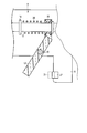
- FIG. 3 is a diagram illustrating an internal configuration of the housing 4.
- a movable member 17 extends along the longitudinal axis C inside the housing 4.
- the movable member 17 is movable along the longitudinal axis C with respect to the housing 4.
- the movable member 17 is connected to at least one of the first gripping piece 13 and the second gripping piece 14 via a movable pipe (not shown) extending along the longitudinal axis C inside the sheath 5.
- a movable pipe not shown
- the movable member 17 is provided with a protruding portion 19 that protrudes toward the outer peripheral side. Further, a slide member 18 is disposed on the outer peripheral portion of the movable member 17 so as to be spaced apart from the protruding portion 19 toward the proximal end side.
- a coil spring 20 that is an elastic member is provided between the protruding portion 19 and the slide member 18. The proximal end of the coil spring 20 is connected to the slide member 18, and the distal end of the coil spring 20 is connected to the protruding portion 19.
- the length of the coil spring 20 in the natural state is L0.
- the coil spring 20 is attached in a reference state in which the treatment target is not disposed between the gripping pieces 13 and 14 and contracted by a displacement amount x0 from the natural state. At this time, the elastic force k0x0 acts on the movable member 17 from the coil spring 20 by setting the elastic coefficient of the coil spring 20 to k0.
- the handle 12 is connected to the slide member 18.
- the handle 12 is connected to the housing 4 via a fulcrum pin 15.
- the handle 12 rotates with respect to the housing 4 around the fulcrum pin 15 and opens or closes with respect to the grip 11.
- the grip 11 is provided with a contact member 21. When the handle 12 is closed with respect to the grip 11, the handle 12 comes into contact with the contact member 21.
- the operator When grasping the treatment target between the grasping pieces 13 and 14, the operator holds the grip 11 and presses the handle 12 toward the grip 11. Then, the handle 12 is closed with respect to the grip 11 until the handle 12 contacts the contact member 21 of the grip 11. As a result, the handle 12 rotates about the fulcrum pin 15, and at the same time, the slide member 18, the movable member 17, and the movable pipe (not shown) are moved integrally along the longitudinal direction to the distal end side. As a result, at least one of the gripping pieces 13 and 14 is closed with respect to the other. That is, the end effector 6 is closed.
- the coil spring 20 does not contract from the reference state, and the elastic force acting on the movable member 17 from the coil spring 20 does not change from k0x0.
- the elastic force that acts on the movable member 17 from the coil spring 20 when the coil spring 20 further contracts from the reference state is k0 (x0 + x), which is the reference state. It becomes larger than the elastic force k0x0.
- the elastic force k0 (x0 + x) larger than the elastic force k0x0 in the reference state acts on the movable member 17 from the coil spring 20, the first gripping piece 13 and the second gripping piece 13 are compared with those in the reference state.
- the gripping force applied to the treatment target gripped with the gripping piece 14 increases. That is, the gripping force applied to the treatment target gripped between the pair of gripping pieces 13 and 14 is determined according to the displacement amount (shrinkage amount) x that the coil spring 20 contracts.
- the gripping force adjusting unit 41 adjusts the gripping force applied to the treatment target gripped between the gripping pieces 13 and 14.
- the aforementioned abutting member 21 provided on the grip 11 serves as a gripping force adjustment unit 41.
- the abutting member 21 moves in the longitudinal direction with respect to the grip 11 by driving a driving member 42 (see FIG. 2) provided inside the housing 4.
- a driving member 42 for example, an electric motor or the like is used.
- a switching operation unit 44 such as a lever is attached to the housing 4, and the contact member 21 is moved relative to the grip 11 by manually operating the switching operation unit 44. It may be moved in the longitudinal direction.
- the movement amount (stroke) until the handle 12 contacts the contact member 21 is increased. Change.
- the amount of movement of the slide member 18 connected to the handle 12 with respect to the movable member 17 in the longitudinal direction changes.
- the amount of displacement (contraction amount) of the coil spring 20 changes.
- the gripping force applied to the treatment target is determined by the amount of displacement of the coil spring 20. For this reason, the gripping force applied to the treatment target can be changed by changing the position of the contact member 21.
- the coil spring 20 contracts by the displacement amount x1 from the reference state in a state where the handle 12 is in contact with the contact member 21. .
- the elastic force k0 (x0 + x1) acts on the movable member 17 from the coil spring 20, and the gripping force for gripping the blood vessel between the gripping pieces 13 and 14 becomes the first gripping force.
- the contact member 21 is positioned at the second position (the position indicated by the broken line in FIG. 3) on the tip side from the first position, the coil spring 20 is in a state where the handle 12 is in contact with the contact member 21.
- the displacement x2 is smaller than the displacement x1 from the reference state.
- the elastic force k0 (x0 + x2) smaller than the elastic force k0 (x0 + x1) acts on the movable member 17 from the coil spring 20, and the gripping force for gripping the blood vessel between the gripping pieces 13, 14 is smaller than the first gripping force.
- This is the second gripping force.
- the gripping force applied to the treatment target is changed by changing the position of the contact member 21 that is the gripping force adjusting unit 41 by the driving member 42 or the switching operation unit 44.
- FIG. 4 is a diagram showing an internal configuration of the housing 4 in the present modification.
- a ring-shaped member 19 a is arranged on the outer peripheral portion of the movable member 17 along the circumferential direction of the movable member 17 (the direction around the longitudinal axis C). It is installed.
- One end (tip) of the coil spring 20 is connected to the ring-shaped member 19a.
- the ring-shaped member 19a includes an inclined surface 25 that is inclined toward the inner peripheral side as it goes toward the distal end side.
- a rod-shaped member 22 is in contact with the ring-shaped member 19a from the tip side.
- a drive member 42 (see FIG. 2) is provided inside the housing 4, and by driving the drive member 42, the rod-shaped member 22 moves in the radial direction of the ring-shaped member 19a.
- the rod-shaped member 22 abuts on the inclined surface 25, and the ring-shaped member 19 a is restricted from moving toward the distal end side by the rod-shaped member 22.
- an electric motor or the like is used for the drive member 42.
- a switching operation portion 44 such as a lever is attached to the housing 4, and the switching operation portion 44 is manually operated, whereby the rod-shaped member 22 is changed to the diameter of the ring-shaped member 19a. It may be moved in the direction.
- the coil spring 20 corresponds to the position of the rod-shaped member 22 in the radial direction from the natural state when the treatment target is not disposed between the gripping pieces 13 and 14 (that is, the reference state).
- the displacement amount (shrinkage amount) x0 changes.
- the coil spring 20 contracts by the displacement amount xa0 from the natural state in the reference state.
- the elastic force k0xa0 acts on the movable member 17 from the coil spring 20.
- the elastic force k0 (xa0 + x) acts on the movable member 17 from the coil spring 20.
- the rod-shaped member 22 is located at a second position (position indicated by a broken line in FIG. 4) outside the first position in the radial direction of the ring-shaped member 19a, the rod-shaped member 22 is located at the first position.
- the pressing force acting on the ring-shaped member 19a from the rod-shaped member 22 is reduced.
- the ring-shaped member 19a is located on the distal end side as compared with the case where the rod-shaped member 22 is located at the first position.
- the coil spring 20 contracts by a displacement amount xb0 that is smaller than the displacement amount xa0 from the natural state in the reference state.
- the elastic force k0xb0 smaller than the elastic force k0xa0 acts on the movable member 17 from the coil spring 20.
- the gripping force applied to the treatment target is reduced compared to when the rod-shaped member 22 is positioned at the first position.
- the gripping force for gripping the blood vessel between the gripping pieces 13 and 14 becomes the first gripping force
- the rod-shaped member 22 is at the second position.
- the gripping force for gripping the blood vessel between the gripping pieces 13 and 14 becomes a second gripping force smaller than the first gripping force.
- the bar-shaped member 22 becomes the gripping force adjusting unit 41, and the bar-shaped member 22 is moved in the radial direction of the ring-shaped member 19a by the driving member 42 or the switching operation unit 44.
- the gripping force applied to can be changed.
- the bar member 23 and the stopper 24 may be provided as the gripping force adjusting unit 41.
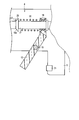
- FIG. 5 is a diagram illustrating the inside of the sheath 5 and the configuration of the end effector 6 in the present modification. As shown in FIG.
- the end effector 6 is rotatable to the first gripping piece 13 provided at the distal end portion of the rod member 16 inserted through the sheath 5 and the distal end portion of the sheath 5.
- a second gripping piece 14 connected to the head. That is, one of the pair of gripping pieces 13 and 14 rotates with respect to the other.
- a bar member 23 extends along the longitudinal direction. The bar member 23 is provided on the side opposite to the first facing surface 31 with respect to the longitudinal axis C.
- a drive member 42 (see FIG. 2) is provided inside the housing 4, and the bar member 23 moves in the longitudinal direction with respect to the rod member 16 by driving the drive member 42.
- a switching operation portion 44 such as a lever is attached to the housing 4, and the switching member 44 is manually operated to move the bar member 23 relative to the rod member 16. It may be moved in the longitudinal direction.
- a stopper 24 that comes into contact with the outer peripheral surface of the rod member 16 is provided at the tip of the bar member 23.
- the stopper 24 is made of, for example, PTFE (polytetrafluoroethylene) having excellent wear resistance.
- the stopper 24 is disposed between the rod member 16 and the sheath 5. At the position where the stopper 24 comes into contact with the rod member 16, the rod member 16 is supported in the opening operation direction of the second gripping piece 14. And in the position where the stopper 24 contacts the rod member 16, the bending of the rod member 16 in the closing operation direction of the second gripping piece 14 is suppressed.
- the first gripping piece 13 and the rod member 16 move from the second gripping piece 14 to the closing operation direction of the second gripping piece 14. Receives pressing force.
- the rod member 16 is bent (curved) from the position supported by the stopper 24 to the tip of the rod member 16 in the closing operation direction of the second gripping piece 14. In other words, the portion of the rod member 16 from the position supported by the stopper 24 to the tip of the rod member 16 becomes a portion that is bent by the pressing force in the closing operation direction of the second gripping piece 14.
- the magnitude of the gripping force applied to the treatment target gripped between the first gripping piece 13 and the second gripping piece 14 is the first gripping piece in the closing operation direction of the second gripping piece 14. 13 corresponding to the amount of deflection.
- the bar member 23 and the stopper 24 serve as the gripping force adjustment unit 41.
- the position at which the rod member 16 is supported by the stopper 24 changes.
- the length from the position where the rod member 16 is supported to the tip of the rod member 16 changes, and the second gripping piece 14 moves in the closing operation direction.
- the amount of bending of the first gripping piece 13 changes.
- the stopper 24 is positioned at the first position (the position indicated by the solid line in FIG. 5)
- the rod member 16 has a first length from the position supported by the stopper 24 to the tip of the rod member 16.
- the amount of bending of the first gripping piece 13 in the closing operation direction of the second gripping piece 14 is the first amount of bending. Further, when the stopper 24 is located at the second position (the position indicated by the broken line in FIG. 5) on the proximal side from the first position, the length from the position supported by the stopper 24 to the tip of the rod member 16 is The second length is longer than the first length. Then, the amount of bending of the first gripping piece 13 in the closing operation direction of the second gripping piece 14 becomes a second amount of bending larger than the first amount of bending.
- the stopper 24 when the stopper 24 is positioned at the second position, the stopper 24 is gripped between the first gripping piece 13 and the second gripping piece 14 as compared with the case where the stopper 24 is positioned at the first position.
- the magnitude of the gripping force applied to the treatment target is reduced. For example, when the stopper 24 is positioned at the first position, the gripping force for gripping the blood vessel between the gripping pieces 13 and 14 becomes the first gripping force, whereas the stopper 24 is positioned at the second position. In this case, the gripping force for gripping the blood vessel between the gripping pieces 13 and 14 becomes a second gripping force smaller than the first gripping force.
- the bar member 23 and the stopper 24 serve as the gripping force adjustment unit 41, and the bar member 23 and the stopper 24 are moved in the longitudinal direction with respect to the rod member 16 by the driving member 42 or the switching operation unit 44. By moving, the gripping force applied to the treatment target can be changed.
- the first gripping piece 13 that can rotate around the longitudinal axis C with respect to the gripping piece 14 is a gripping force adjusting portion 41 (see FIG. 2). It may be provided.
- FIG. 6 is a cross-sectional view showing the end effector 6 in a cross section substantially parallel to the longitudinal axis C in the present modification.
- the base end portion of the first gripping piece 13 is connected to the driving member 42 (see FIG. 2), and the driving member 42 is driven so that the first gripping piece 13 becomes the second gripping piece. 14 rotates around the longitudinal axis C.
- the first gripping piece rotates in the direction around the longitudinal axis C with respect to the second gripping piece 14, the surface that becomes the first facing surface 31 that faces the second facing surface 32 is switched, The thickness of one gripping piece 13 in the opening / closing direction of the first gripping piece 13 changes.
- the drive member 42 for example, an electric motor or the like is used.
- a switching operation unit 44 such as a lever is attached to the housing 4, and the first gripping piece 13 is moved relative to the second gripping piece 14 by manually operating the switching operation unit 44. And may be rotated in the direction around the longitudinal axis C.
- the first gripping piece 13 When the second gripping piece 14 is closed with respect to the first gripping piece 13, the first gripping piece 13 receives a pressing force from the second gripping piece 14 in the closing operation direction of the second gripping piece 14. .
- the first gripping piece 13 bends (curves) in the closing operation direction of the second gripping piece 14.
- the amount of bending of the first gripping piece 13 in the closing operation direction of the second gripping piece 14 changes in accordance with the thickness of the first gripping piece 13 in the opening / closing direction of the second gripping piece 14.
- the magnitude of the gripping force applied to the treatment target gripped between the first gripping piece 13 and the second gripping piece 14 is the first in the closing operation direction of the second gripping piece 14. It changes corresponding to the amount of bending of the gripping piece 13.
- the first gripping piece 13 becomes the gripping force adjusting unit 41.
- the surface facing the second facing surface 32 is switched as the first facing surface 31.
- the thickness of the first gripping piece 13 in the opening / closing direction of the second gripping piece 14 changes.
- the amount of bending of the first gripping piece 13 in the closing operation direction of the second gripping piece 14 changes.
- the second gripping piece 14 moves in the closing operation direction.
- the amount of bending of the first gripping piece 13 is the first amount of bending.
- the thickness of the first gripping piece 13 in the opening / closing direction of the second gripping piece 14 is the second thickness smaller than the first thickness (indicated by the broken line in FIG. 6)
- the second gripping piece The amount of bending of the first gripping piece 13 in the closing operation direction 14 is a second amount of bending larger than the first amount of bending.
- the first gripping piece 13 in the opening / closing direction of the second gripping piece 14 is the second thickness
- the first gripping piece 13 in the opening / closing direction of the second gripping piece 14 is The magnitude of the gripping force applied to the treatment target gripped between the first gripping piece 13 and the second gripping piece 14 is smaller than when the thickness is the first thickness.
- the gripping force for gripping the blood vessel between the gripping pieces 13 and 14 is the first gripping force.
- the gripping force for gripping the blood vessel between the gripping pieces 13 and 14 Becomes a second gripping force smaller than the first gripping force.
- the first gripping piece 13 becomes the gripping force adjusting unit 41, and the first gripping piece 13 is moved with respect to the second gripping piece 14 by the driving member 42 or the switching operation unit 44. By rotating in the direction around the longitudinal axis C, the gripping force applied to the treatment target can be changed.
- a ratchet in which a plurality of grooves (not shown) are formed inside the housing 4 and a claw (not shown) extending from the handle 12 toward the ratchet groove.
- a plurality of groove portions that are fitted to the claw portions when the handle 12 is closed with respect to the grip 11 are arranged in the housing 4 along the longitudinal direction.
- the handle 12 moves to the proximal side along the longitudinal direction.
- the claw portion is fitted with one groove portion among the plurality of groove portions.
- the handle 12 when the handle 12 is further closed with respect to the grip 11, the handle 12 further moves to the proximal end side along the longitudinal direction. At this time, the claw portion is fitted with another one of the plurality of groove portions. That is, when the handle 12 is closed with respect to the grip 11, the groove portion to be fitted to the claw portion is switched by selecting a position where the handle 12 moves.
- the claw portion becomes the gripping force adjustment portion 41.
- the groove portion that engages with the claw portion is switched, whereby the movement amount (stroke) of the handle 12 when the handle 12 is closed with respect to the grip 11 is changed.
- the movement amount (stroke) of the handle 12 when the handle 12 is closed with respect to the grip 11 is changed, so that the slide member 18 connected to the handle 12 moves in the longitudinal direction with respect to the movable member 17. Changes.
- the amount of displacement (contraction amount) of the coil spring 20 changes.
- the gripping force applied to the treatment target is determined by the amount of displacement of the coil spring 20.
- the gripping force applied to the treatment target by switching the groove into which the claw portion is fitted.
- the claw portion of the handle 12 is fitted to the first groove portion that is one of the groove portions
- the movement amount of the handle 12 by the closing operation becomes the first movement amount.
- the coil spring 20 contracts by a displacement amount x1 from the reference state.
- the elastic force k0 (x0 + x1) acts on the movable member 17 from the coil spring 20, and the gripping force for gripping the blood vessel between the gripping pieces 13 and 14 becomes the first gripping force.
- the movement amount of the handle 12 by the closing operation is smaller than the first movement amount.
- the coil spring 20 contracts by a displacement amount x2 smaller than the displacement amount x1 from the reference state.
- the elastic force k0 (x0 + x2) smaller than the elastic force k0 (x0 + x1) acts on the movable member 17 from the coil spring 20, and the gripping force for gripping the blood vessel between the gripping pieces 13, 14 is smaller than the first gripping force. This is the second gripping force.
- the gripping force adjusting unit may be configured to change the gripping force applied to the treatment target (blood vessel) according to the operating state.
- the detection unit 43 detects information (parameters) related to a blood vessel gripped between the gripping pieces 13 and 14.
- information parameters related to a blood vessel gripped between the gripping pieces 13 and 14.
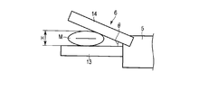
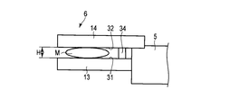
- FIG. 7 is a diagram showing the end effector 6 and the blood vessel M in a state where the blood vessel M gripped between the gripping pieces 13 and 14 is compressed to some extent in the opening / closing direction of the end effector 6.
- the grasped blood vessel M is compressed to some extent in the opening / closing direction of the end effector 6, the upper and lower inner walls of the blood vessel M are close to each other.
- the dimension H of the blood vessel M in the opening / closing direction of the end effector 6 in a state where the grasped blood vessel M is compressed to some extent in the opening / closing direction of the end effector 6 is substantially proportional to the wall thickness T of the blood vessel.
- the angle ⁇ of the second grasping piece with respect to the first grasping piece 13 is grasped between the grasping pieces 13 and 14. It is proportional to the dimension H of the blood vessel M in the opening / closing direction of the end effector 6.
- the angle ⁇ of the second grasping piece with respect to the first grasping piece 13 is substantially proportional to the wall thickness T of the blood vessel M.
- the pressure sensor 34 is provided as a detection unit 43 at the base end of the second facing surface 32.
- FIG. 8 is a diagram illustrating the end effector 6 in an embodiment. As shown in FIG. 8, in this embodiment, the pressure sensor 34 projects in the closing direction of the second gripping piece 14 on the second facing surface 32.
- the pressure sensor 34 is electrically connected to the processor 47 of the energy control device 3 via an electric circuit (not shown) formed inside the energy treatment device 2.
- the pressure sensor 34 receives a pressing force from the first facing surface 31. For this reason, when the pressure sensor 34 is in contact with the first facing surface 31, the pressure P received by the pressure sensor 34 is larger than when the pressure sensor 34 is not in contact with the first facing surface 31.
- FIGS. 9 and 10 are diagrams showing the end effector 6 and the blood vessel M in a state where the blood vessels M having different wall thicknesses T are compressed to some extent in the opening / closing direction of the end effector 6.
- the wall thickness T of the grasped blood vessel M is larger than the predetermined thickness Tth, the dimension H in a state where the blood vessel M is compressed to some extent in the opening / closing direction of the end effector 6 becomes thick. For this reason, the pressure sensor 34 does not contact the first facing surface 31, and the pressure received by the pressure sensor 34 is reduced.
- a detection signal indicating the detection result of the pressure sensor 34 is input to the setting unit 51 of the processor 47.
- information on the pressure received by the pressure sensor 34 as information regarding the blood vessel M is input to the setting unit 51.
- the setting unit 51 determines that the pressure P received by the pressure sensor 34 is smaller than the threshold value Pth based on the detection signal from the pressure sensor 34.
- the setting unit 51 determines that the wall thickness T of the grasped blood vessel M is thicker than the predetermined thickness Tth. At this time, the setting unit 51 may determine that the grasped blood vessel M is a blood vessel in the systemic circulation system having a relatively thick wall thickness T.
- the setting unit 51 determines that the pressure P received by the pressure sensor 34 is greater than or equal to the threshold value Pth based on the detection signal from the pressure sensor 34.
- the setting unit 51 determines that the wall thickness T of the grasped blood vessel M is equal to or less than the predetermined thickness Tth. At this time, the setting unit 51 may determine that the grasped blood vessel M is a blood vessel of the pulmonary circulatory system having a relatively thin wall thickness T.
- the pressure sensor 34 detects the pressure P received by the pressure sensor 34 as information (parameter) related to the blood vessel M. Further, based on the detection signal from the pressure sensor 34, the setting unit 51 can obtain information regarding the wall thickness T of the blood vessel M. Then, the setting unit 51 determines whether or not the wall thickness T of the blood vessel M is greater than a predetermined thickness Tth based on the information related to the blood vessel M (information on the pressure received by the pressure sensor 34) input to the setting unit 51. Alternatively, information on the wall thickness T, such as the type of blood vessel M (systemic circulation system or lung circulation system), is set. That is, in the present modification, the pressure sensor 34 serves as the detection unit 43 and detects information related to the grasped blood vessel M.
- the pressure sensor 34 serves as the detection unit 43 and detects information related to the grasped blood vessel M.
- only one pressure sensor 34 is provided on the second facing surface 32, but this is not restrictive.
- the pressure sensor 34 may be provided at each of the proximal end portion and the distal end portion of the second facing surface 32.
- the pressure sensor 34 may be provided at the proximal end portion of the first facing surface 31. That is, one or more pressure sensors 34 may be provided on at least one of the first facing surface 31 and the second facing surface 32.
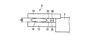
- conductive members 35 and 36 may be provided as the detection unit 43 instead of the pressure sensor 34.
- 11 and 12 are diagrams showing the end effector 6 and the blood vessel M in a state where the blood vessels M having different wall thicknesses T are compressed to some extent in the opening / closing direction of the end effector 6 in the present modification.
- a first conductive member 35 protruding in the closing operation direction of the first gripping piece 13 is provided at the proximal end portion of the first facing surface 31.
- a second conductive member 36 that protrudes in the closing operation direction of the second gripping piece 14 is provided at the proximal end portion of the second facing surface 32 so as to face the first conductive member 35.
- the first conductive member 35 and the second conductive member 36 are supplied from the power supply unit 46 of the energy control device 3 with electric energy different from the electric energy converted into driving power and treatment energy.
- the wall thickness T of the grasped blood vessel M is relatively thick (for example, when it is thicker than the predetermined thickness Tth)
- the above-mentioned dimension H becomes thick, so that the first conductive member 35 and The second conductive member 36 does not come into contact. For this reason, no current flows in the electric circuit passing through the first conductive member 35, the second conductive member 36 and the power supply unit 46.
- the setting unit 51 determines that the wall thickness T of the blood vessel M is thicker than the predetermined thickness Tth based on the fact that no current flows in the electric circuit described above, or the blood vessel M to be grasped is
- the blood vessel is determined to be a blood vessel of the systemic circulation system having a relatively thick wall thickness T.
- the wall thickness T of the grasped blood vessel M is relatively thin (for example, when the wall thickness T is equal to or smaller than the predetermined thickness Tth)
- the above-described dimension H becomes thin. Therefore, the first conductive member and the second conductive member Abut. For this reason, a current flows through an electric circuit passing through the first conductive member, the second conductive member, and the power supply unit 46.
- the setting unit 51 determines that the wall thickness T of the blood vessel M is equal to or less than a predetermined thickness Tth based on the current flowing through the electric circuit described above, or the blood vessel M to be grasped is
- the blood vessel is judged to be a blood vessel of the pulmonary circulatory system having a relatively thin wall thickness T.
- the first conductive member 35 and the second conductive member 36 that are the detection unit 43 are used to pass through the first conductive member 35, the second conductive member 36, and the power supply unit 46. Whether or not a current flows through is detected as information about the blood vessel M.
- the setting unit 51 determines whether the wall thickness T of the blood vessel M is thicker than a predetermined thickness wall thickness Tth based on the detected information about the blood vessel M, or the type of the blood vessel M (systemic circulation system or lung circulation system). ) And the like regarding the wall thickness T are set.
- an angle sensor 37 may be provided as the detection unit 43 as shown in FIG.
- FIG. 13 is a diagram illustrating the end effector 6 and the blood vessel M in a state in which the blood vessel M gripped between the gripping pieces 13 and 14 is compressed to some extent in the opening / closing direction of the end effector 6 in this modification.
- an angle sensor 37 is provided at the connecting portion between the second gripping piece 14 and the sheath 5.
- the angle sensor 37 detects the angle ⁇ between the first grip piece 13 and the second grip piece.
- an encoder or a potentiometer is used for the angle sensor 37.
- the angle sensor 37 is electrically connected to the processor 47 of the energy control device 3 via a signal path (not shown) formed inside the energy treatment device 2.
- the angle sensor 37 serving as the detection unit 43 is used in a state in which the blood vessel M gripped between the gripping pieces 13 and 14 is compressed to some extent in the opening / closing direction of the end effector 6. For example, when the wall thickness T of the blood vessel M to be grasped is thicker than the predetermined thickness Tth, the angle ⁇ between the first grasping piece 13 and the second grasping piece 14 becomes large.
- a detection signal indicating the detection result of the angle sensor 37 is input to the setting unit 51 of the processor 47. At this time, the angle ⁇ between the first gripping piece 13 and the second gripping piece 14 is input to the setting unit 51 as information regarding the blood vessel M.
- the setting unit 51 determines that the angle ⁇ between the first gripping piece 13 and the second gripping piece 14 is larger than the threshold ⁇ th based on the detection signal from the angle sensor 37.
- the setting unit 51 determines that the wall thickness T of the grasped blood vessel M is the predetermined thickness Tth. Judge that it is thicker. At this time, the setting unit 51 may determine that the grasped blood vessel M is a blood vessel in the systemic circulation system having a relatively thick wall thickness T.
- the angle ⁇ between the first grasping piece 13 and the second grasping piece becomes small.
- a detection signal indicating a detection result (information on the blood vessel M) by the angle sensor 37 is input to the setting unit 51.
- the setting unit 51 determines that the angle ⁇ between the first grip piece 13 and the second grip piece 14 is equal to or less than the threshold ⁇ th.
- the angle ⁇ between the first gripping piece 13 and the second gripping piece 14 is small.
- the setting unit 51 determines that the wall thickness T of the blood vessel M to be gripped is a predetermined thickness. Judged to be Tth or less. At this time, the setting unit 51 may determine that the grasped blood vessel M is a blood vessel of the pulmonary circulatory system having a relatively thin wall thickness T.
- the angle sensor 37 detects the angle ⁇ between the first gripping piece 13 and the second gripping piece 14 as information (parameter) related to the blood vessel M. Further, based on the detection signal from the angle sensor 37, the setting unit 51 can obtain information regarding the wall thickness T of the blood vessel M. And the setting part 51 is based on the information regarding the blood vessel M (the information on the angle ⁇ between the first gripping piece 13 and the second gripping piece 14) input to the setting part 51, and the wall thickness T of the blood vessel M. Is set to information on the wall thickness T, such as whether or not is greater than a predetermined thickness Tth, or the type of the blood vessel M (systemic circulation system or lung circulation system). That is, in the present modification, the angle sensor 37 serves as the detection unit 43 and detects information regarding the grasped blood vessel M.
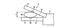
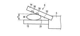
- a light receiving element 39 may be provided as the detection unit 43 as shown in FIG.
- FIG. 14 is a diagram illustrating the end effector 6 and the blood vessel M in a state in which the blood vessel M gripped between the gripping pieces 13 and 14 is compressed to some extent in the opening / closing direction of the end effector 6 in the present modification.
- a light emitting element 38 such as an LED is provided on the second facing surface 32.
- the first facing surface 31 is provided with a light receiving element 39 such as a PD.
- the light receiving element 39 is electrically connected to the processor 47 of the energy control device 3 via a signal path (not shown) formed inside the energy treatment instrument 2.
- the light emitting element 38 emits light toward the light receiving element 39 when electric energy different from the electric energy converted into the driving force and the treatment energy is supplied from the energy control device 3.
- the light receiving element 39 detects the amount (light quantity) Q of light incident on the light receiving element 39.
- the detection unit 43 is used in a state where the blood vessel M gripped between the gripping pieces 13 and 14 is compressed to some extent in the opening / closing direction of the end effector 6. At this time, the light emitting element 38 emits light toward the blood vessel M and the light receiving element 39. A part of the light emitted to the blood vessel M is reflected or absorbed by the blood vessel tissue inside the blood vessel M. Of the light emitted to the blood vessel M, light (transmitted light) that is not reflected by the blood vessel tissue and is not absorbed enters the light receiving element 39. The light receiving element 39 detects the light quantity Q of the transmitted light.
- the wall thickness T of the grasped blood vessel M is larger than the predetermined thickness Tth, the dimension H in a state where the blood vessel M is compressed to some extent in the opening / closing direction of the end effector 6 becomes thick. For this reason, of the light emitted to the blood vessel M, the amount of light reflected or absorbed by the blood vessel tissue increases. As the amount of light reflected or absorbed by the vascular tissue increases, the amount of transmitted light Q incident on the light receiving element 39 decreases.
- a detection signal indicating the detection result of the light receiving element 39 is input to the setting unit 51 of the processor 47. At this time, information on the light quantity Q of transmitted light incident on the light receiving element 39 as information on the blood vessel M is input to the setting unit 51.
- the setting unit 51 determines that the amount of transmitted light Q incident on the light receiving element 39 is smaller than the threshold value Qth based on the detection signal from the light receiving element 39.
- the setting unit 51 determines that the wall thickness T of the grasped blood vessel M is larger than the predetermined thickness Tth. At this time, the setting unit 51 may determine that the grasped blood vessel M is a blood vessel in the systemic circulation system having a relatively thick wall thickness T.
- the wall thickness T of the grasped blood vessel M is equal to or smaller than the predetermined thickness Tth, the dimension H in a state where the blood vessel M is compressed to some extent in the opening / closing direction of the end effector 6 becomes thin. For this reason, among the light emitted to the blood vessel M, the amount of light reflected or absorbed by the blood vessel tissue is reduced. As the amount of light reflected or absorbed by the blood vessel tissue decreases, the amount of transmitted light Q incident on the light receiving element 39 increases. A detection signal indicating the detection result of the light receiving element 39 is input to the setting unit 51 of the processor 47. At this time, information on the light quantity Q of transmitted light incident on the light receiving element 39 as information on the blood vessel M is input to the setting unit 51.
- the setting unit 51 determines that the light quantity Q of the transmitted light incident on the light receiving element 39 is equal to or greater than the threshold value Qth.
- the setting unit 51 determines that the wall thickness T of the grasped blood vessel M is equal to or less than the predetermined thickness Tth. To do. At this time, the setting unit 51 may determine that the grasped blood vessel M is a blood vessel of the pulmonary circulatory system having a relatively thin wall thickness T.
- the light receiving element 39 detects the amount Q of transmitted light incident on the light receiving element 39 as information (parameters) on the blood vessel M. Further, based on the detection signal from the light receiving element 39, the setting unit 51 can obtain information regarding the wall thickness T of the blood vessel M. Then, the setting unit 51 determines that the wall thickness T of the blood vessel M is greater than the predetermined thickness Tth based on the information related to the blood vessel M (information on the amount of transmitted light Q incident on the light receiving element 39) input to the setting unit 51. Information regarding the wall thickness T, such as whether the thickness is thick or the type of the blood vessel M (systemic circulation system or pulmonary circulation system), is set. That is, in the present modification, the light receiving element 39 serves as the detection unit 43 and detects information regarding the grasped blood vessel M.
- the light emitting element 38 is provided on the second facing surface 32 and the light receiving element 39 is provided on the first facing surface 31, but this is not restrictive.
- the light emitting element 38 may be provided on the first facing surface 31 and the light receiving element 39 may be provided on the second facing surface 32.
- both the light emitting element 38 and the light receiving element 39 may be provided on the second facing surface 32.
- the light receiving element 39 detects the amount of light emitted from the light emitting element 38 and reflected by the first facing surface 31 and incident on the light receiving element 39.
- both the light emitting element 38 and the light receiving element 39 may be provided on the first facing surface 31.
- the information regarding the blood vessel used in this modification is not limited to the light amount.
- ultrasonic waves may be used instead of light.
- an ultrasonic echo diagnostic apparatus (not shown) is provided as the detection unit 43.
- an ultrasonic wave is emitted from the ultrasonic wave transmitting unit to the blood vessel M, and an ultrasonic wave passing through the inside of the blood vessel M is detected by the ultrasonic wave receiving unit.
- the setting unit 51 of the processor 47 information on the emitted ultrasonic waves and information on the detected ultrasonic waves are input to the setting unit 51 of the processor 47.
- information on the emitted ultrasound and information on the detected ultrasound are input to the setting unit 51 as information related to the blood vessel M.
- the setting unit 51 visualizes the inside of the blood vessel M using a time difference between the time when the ultrasonic wave is emitted and the time when the ultrasonic wave is detected.
- the setting unit 51 determines that the wall thickness T of the grasped blood vessel M is larger than the predetermined thickness Tth (or less than the predetermined thickness Tth) based on the visualized internal image of the blood vessel M.
- the setting unit 51 may determine that the grasped blood vessel M is a blood vessel of the systemic circulation system having a relatively thick wall thickness T (or a blood vessel of the lung circulation system having a relatively thin wall thickness T).
- the detection unit 43 is provided inside the housing 4, and the coil spring 20 from the reference state in a state where the grasped blood vessel M is compressed to some extent in the opening / closing direction of the end effector 6.
- the displacement amount (shrinkage amount) x may be detected.
- a detection signal indicating the detection result of the detection unit 43 is input to the setting unit 51 of the processor 47.
- the displacement amount (shrinkage amount) x of the coil spring 20 from the above-described reference state is input to the setting unit 51 as information regarding the blood vessel M.
- the displacement amount (shrinkage amount) x of the coil spring 20 from the above-described reference state changes according to the above-described dimension H in a state where the grasped blood vessel M is compressed to some extent in the opening / closing direction of the end effector 6.
- the dimension H is substantially proportional to the wall thickness T of the blood vessel M. Therefore, the setting unit 51 determines that the wall thickness T of the grasped blood vessel M is greater than the predetermined thickness Tth (or less than the predetermined thickness Tth) based on the displacement amount (contraction amount) x of the coil spring 20 from the reference state.
- the setting unit 51 may determine that the grasped blood vessel M is a blood vessel of the systemic circulation system having a relatively thick wall thickness T (or a blood vessel of the lung circulation system having a relatively thin wall thickness T). .
- an electric circuit (not shown) that passes through electrodes (not shown) and a power supply unit 46 provided on each of the first holding piece 13 and the second holding piece 14. ) May be provided.
- electrodes are provided on each of the first grip piece 13 and the second grip piece 14, and electric energy (high-frequency power) output from the power supply unit 46 of the energy control device 3 is applied to these electrodes. Supplied.
- electrical energy is supplied to these electrodes while the blood vessel is gripped between the first gripping piece 13 and the second gripping piece 14, a high-frequency current flows between the electrodes through the blood vessel.
- the treatment energy is gripped through the first facing surface 31 of the first gripping piece 13 and the second facing surface 32 of the second gripping piece 14 which are energy applying portions.
- a high frequency current is applied to the blood vessel as treatment energy.
- a high-frequency current is not applied to the blood vessel as treatment energy, a high-frequency current that does not denature the grasped blood vessel flows through the blood vessel. And the high frequency current which flows through the blood vessel with the above-mentioned electric circuit is detected.
- the detection unit 43 is used in a state where the blood vessel M gripped between the gripping pieces 13 and 14 is compressed to some extent in the opening / closing direction of the end effector 6. At this time, an electric circuit is formed that passes through the electrodes, blood vessels M, and power supply units 46 provided on the gripping pieces 13 and 14 respectively.
- electric energy high frequency power
- a high frequency current flows through the blood vessel M in the electric circuit. Then, the current flowing through the blood vessel M in this electric circuit is input to the setting unit 51 as information on the blood vessel.
- the wall thickness T of the grasped blood vessel M is larger than the predetermined thickness Tth, the dimension H in a state where the blood vessel M is compressed to some extent in the opening / closing direction of the end effector 6 becomes thick. For this reason, the amount of water contained in the cross section of the blood vessel M in the opening / closing direction of the end effector 6 increases.
- the impedance Z (electrical resistance) of the blood vessel M decreases as the amount of water contained in the cross-section in the opening / closing direction of the end effector 6 of the blood vessel M increases.
- the impedance Z (electrical resistance) of the blood vessel M decreases.
- the setting unit 51 calculates the impedance Z of the blood vessel M based on the detection result of the detection unit 43 (high-frequency current flowing through the blood vessel M in the electric circuit), and based on the calculation result, the impedance Z of the blood vessel M is based on the threshold value Zth. Judge that it is small. As described above, when the wall thickness T of the blood vessel M is thick, the impedance Z of the blood vessel M in a state where the blood vessel M is compressed to some extent in the opening / closing direction of the end effector 6 becomes small.
- the setting unit 51 determines that the wall thickness T of the grasped blood vessel M is larger than the predetermined thickness Tth. At this time, the setting unit 51 may determine that the grasped blood vessel M is a blood vessel in the systemic circulation system having a relatively thick wall thickness T.
- the wall thickness T of the grasped blood vessel M is equal to or smaller than the predetermined thickness Tth, the above-described dimension H becomes thin. For this reason, the moisture content contained in the cross section of the blood vessel M in the opening / closing direction of the end effector 6 is reduced. As described above, it is known that water has a low electrical resistance. For this reason, the impedance Z (electrical resistance) of the blood vessel M increases as the amount of water contained in the cross-section in the opening / closing direction of the end effector 6 of the blood vessel M decreases. As the amount of water contained in the cross-section in the opening / closing direction of the end effector 6 of the blood vessel M decreases, the impedance Z (electric resistance) of the blood vessel M increases.
- the setting unit 51 calculates the impedance Z of the blood vessel M based on the detection result (characteristics of the current flowing through the blood vessel M) in the detection unit 43, and the impedance Z of the blood vessel M is equal to or greater than the threshold value Zth based on the calculation result.
- the setting unit 51 determines that the wall thickness T of the grasped blood vessel M is equal to or less than the predetermined thickness Tth.
- the setting unit 51 may determine that the grasped blood vessel M is a blood vessel of the pulmonary circulatory system having a relatively thin wall thickness T.
- information (parameters) related to the blood vessel M is obtained using an electrical circuit passing through the electrodes and the power supply unit 46 provided in each of the first gripping piece 13 and the second gripping piece 14.
- a characteristic of the high-frequency current flowing through the grasped blood vessel M is detected.
- the setting unit 51 can obtain information on the wall thickness T of the blood vessel M based on the detection signal indicating the characteristics of the high-frequency current. Then, the setting unit 51 determines whether the wall thickness T of the blood vessel M is larger than a predetermined thickness Tth based on the information related to the blood vessel M (characteristics of the high-frequency current flowing through the grasped blood vessel M) input to the setting unit 51.
- FIG. 17 is a diagram showing a configuration of the heart 100 and its vicinity.
- the heart 100 includes a left atrium 101, a left ventricle 102, a right atrium 103, and a right ventricle 104.
- a pulmonary vein 105 extends from the left atrium 101, and an aorta 106 extends from the left ventricle 102.
- a vena cava 107 is extended from the right atrium 103 and a pulmonary artery 108 is extended from the right ventricle 104.
- a circulation path for guiding blood from the left ventricle 102 to the whole body through the aorta 106 and returning the blood from the whole body to the right atrium 103 through the vena cava 107 is referred to as systemic circulation.
- a circulation path for guiding blood from the right ventricle 104 to the lungs through the pulmonary artery 108 and returning the blood from the lungs to the left atrium 101 through the pulmonary vein 105 is called pulmonary circulation.
- the end effector 6 When treating the blood vessel, the end effector 6 is inserted into the thoracic cavity, and the end effector 6 is moved until the blood vessel is positioned between the first gripping piece 13 and the second gripping piece 14. Then, the handle 12 is closed with respect to the grip 11 in a state where the blood vessel to be treated is disposed between the first gripping piece 13 and the second gripping piece 14. By closing the handle 12 with respect to the grip 11, the blood vessel is compressed to some extent in the opening / closing direction of the end effector 6, and is stretched to some extent in the traveling direction (extending direction) of the blood vessel. Then, the space between the first gripping piece 13 and the second gripping piece 14 is closed, and the blood vessel is gripped.
- the traveling direction of the blood vessel intersects the longitudinal direction, and the first gripping piece 13 and the second gripping piece Intersect each opening and closing direction of the gripping piece 14. Then, when the blood vessel is gripped between the first gripping piece 13 and the second gripping piece 14, an operation input is performed with the operation button 33, so that the ultrasonic vibration, the high-frequency current, and the At least one of heat or the like is applied to the blood vessel as treatment energy, and the blood vessel is sealed (coagulated) simultaneously with the incision.
- the blood vessels of the pulmonary circulatory system are said to have a thinner blood vessel wall thickness T than the blood vessels of the systemic circulatory system.
- the amount in the cross section perpendicular to the extending direction of the biopolymer to be gelatinized in the sealing treatment (joining treatment) is larger than that of the circulatory blood vessels having the same cross-sectional diameter. Less.
- the treatment performance may be affected.
- the information on the blood vessel gripped between the gripping pieces 13 and 14 is detected by the detection unit 43 as described above. Is done.
- Information regarding the wall thickness detected by the detection unit 43 is input to the setting unit 51.
- the setting unit 51 sets information regarding the wall thickness T of the grasped blood vessel.
- the drive control unit 52 determines a parameter regarding the gripping force applied to the treatment target gripped between the gripping pieces 13 and 14.
- the drive control unit 52 sets the first blood vessel to be grasped between the grasping pieces 13 and 14. Decide to apply gripping force. Then, the drive control unit 52 controls the drive power supplied from the drive power output unit 50 to the drive member 42 based on the determination. Thereby, the drive of the drive member 42 is controlled and the action
- the drive control unit 52 sets the first treatment target to be grasped between the grasping pieces 13 and 14. It is determined to apply a second gripping force smaller than the gripping force. Then, the drive control unit 52 controls the drive power supplied from the drive power output unit 50 to the drive member 42 based on the determination. Thereby, the drive of the drive member 42 is controlled and the action
- the gripping force adjusting unit 41 is vascularized between the first gripping piece 13 and the second gripping piece 14.
- the gripping force for gripping the grip is adjusted to the first gripping force, and between the first gripping piece 13 and the second gripping piece 14
- the gripping force for gripping the blood vessel is adjusted to a second gripping force that is smaller than the first gripping force.
- the information regarding the wall thickness T of the blood vessel set by the setting unit 51 of the processor 47 (whether or not the wall thickness T is larger than the predetermined thickness Tth and / or the type of blood vessel) is, for example, the energy control device 3.
- the operator may be notified by a notification unit (not shown) or the like.
- the operator manually operates, for example, the switching operation unit 44 (see FIG. 2) attached to the housing 4 based on the notified information on the wall thickness T of the blood vessel, and the operating state of the gripping force adjustment unit 41 Adjust. Thereby, the gripping force applied to the blood vessel between the gripping pieces 13 and 14 is adjusted.
- the blood vessel when it is notified that the wall thickness T is greater than the predetermined thickness Tth, the blood vessel is gripped between the first gripping piece 13 and the second gripping piece 14 by the operation of the switching operation unit 44.
- the gripping force is adjusted to the first gripping force.
- the blood vessel is grasped between the first grasping piece 13 and the second grasping piece 14 by the operation of the switching operation unit 44.
- the gripping force is adjusted to a second gripping force that is smaller than the first gripping force.
- the information input unit 53 provided in the energy control device 3 may be operated to input information regarding blood vessels.
- the setting unit 51 sets information on the wall thickness T of the grasped blood vessel based on the input result in the information input unit 53 (information on the blood vessel input to the information input unit 53).
- the drive control unit 52 controls the operation of the gripping force adjusting unit 41 or the operator manually operates the switching operation unit 44 to The gripping force applied to the blood vessel between 13 and 14 is adjusted.
- FIG. 18 and 19 show the end effector 6 and the blood vessel M when the first gripping force and the second gripping force are respectively applied to the blood vessel M gripped between the gripping pieces 13 and 14. It is the figure shown with the cross section substantially perpendicular
- the first tensile force F ⁇ b> 1 acts on the blood vessel M in the extending direction of the blood vessel M (the width direction of the end effector 6).
- the second gripping force smaller than the first gripping force is applied to the blood vessel M, the second tension smaller than the first tensile force F1 in the extending direction of the blood vessel M. Force F2 acts.
- the second pulling force F2 is smaller than the first pulling force F2
- the blood vessel M is compared with the case where the first gripping force is applied to the blood vessel.
- the stretching amount of the blood vessel M in the traveling direction (extending direction) decreases.
- the energy surgical device 1 in the present embodiment can provide the energy surgical device 1 suitable for the treatment of sealing a blood vessel having a thin wall thickness T such as a blood vessel of the pulmonary circulation system (simultaneously with the incision).
- a blood vessel having a different wall thickness T is sealed with respect to each other such that the wall thickness T is different between a blood vessel in the pulmonary circulation system and a blood vessel in the systemic circulation system. It is possible to provide an energy surgical device 1 that can exhibit treatment performance.
- the energy surgical instrument (1) can be opened and closed between the first gripping piece (13) and the first gripping piece (13), and the first gripping piece (13). And a second grasping piece (14) capable of grasping a blood vessel with the first grasping piece (13). At least one of the first gripping piece (13) and the second gripping piece (14) is treated with a blood vessel gripped between the first gripping piece (13) and the second gripping piece (14).
- an energy applying unit (31; 32; 31, 32) for treating a blood vessel is provided.
- the energy surgical instrument (1) includes a setting unit 51 that sets information on the wall thickness T of the blood vessel, and the first gripping piece when the wall thickness T set by the setting unit 51 is thicker than a predetermined thickness Tth.
- a gripping force adjusting unit (41) that adjusts the gripping force to a second gripping force that is smaller than the first gripping force.
- Additional item 1 Closing between the first gripping piece and the second gripping piece and gripping the blood vessel between the first gripping piece and the second gripping piece; Setting information on the wall thickness of the vessel being grasped; When the set wall thickness is thicker than a predetermined thickness, the gripping force for gripping the blood vessel between the first gripping piece and the second gripping piece is adjusted to the first gripping force and set. Adjusting the gripping force to a second gripping force smaller than the first gripping force when the wall thickness is less than or equal to a predetermined thickness; Applying treatment energy to the treatment object and sealing the treatment object;
- a treatment method comprising:
Landscapes
- Health & Medical Sciences (AREA)
- Surgery (AREA)
- Life Sciences & Earth Sciences (AREA)
- Engineering & Computer Science (AREA)
- Biomedical Technology (AREA)
- Public Health (AREA)
- Nuclear Medicine, Radiotherapy & Molecular Imaging (AREA)
- Veterinary Medicine (AREA)
- General Health & Medical Sciences (AREA)
- Heart & Thoracic Surgery (AREA)
- Medical Informatics (AREA)
- Molecular Biology (AREA)
- Animal Behavior & Ethology (AREA)
- Otolaryngology (AREA)
- Physics & Mathematics (AREA)
- Plasma & Fusion (AREA)
- Dentistry (AREA)
- Mechanical Engineering (AREA)
- Surgical Instruments (AREA)
Abstract
Description
(付記項1)
第1の把持片と第2の把持片との間を閉じ、前記第1の把持片と前記第2の把持片との間で血管を把持することと、
把持されている前記血管の壁厚に関する情報を設定することと、
設定された前記壁厚が所定の厚みよりも厚い場合、前記第1の把持片と前記第2の把持片との間で前記血管を把持する把持力を第1の把持力に調整し、設定された前記壁厚が所定の厚み以下の場合、前記把持力を前記第1の把持力よりも小さい第2の把持力に調整することと、
前記処置対象に処置エネルギーを付与し、前記処置対象を封止することと、
を具備する処置方法。 The characteristic items are added below.
(Additional item 1)
Closing between the first gripping piece and the second gripping piece and gripping the blood vessel between the first gripping piece and the second gripping piece;
Setting information on the wall thickness of the vessel being grasped;
When the set wall thickness is thicker than a predetermined thickness, the gripping force for gripping the blood vessel between the first gripping piece and the second gripping piece is adjusted to the first gripping force and set. Adjusting the gripping force to a second gripping force smaller than the first gripping force when the wall thickness is less than or equal to a predetermined thickness;
Applying treatment energy to the treatment object and sealing the treatment object;
A treatment method comprising:
Claims (4)
- 第1の把持片と、
前記第1の把持片との間が開閉可能であり、前記第1の把持片との間が閉じることにより、前記第1の把持片との間で血管を把持可能な第2の把持片と、
前記第1の把持片及び前記第2の把持片の少なくとも一方に設けられ、前記第1の把持片と前記第2の把持片との間で把持された前記血管に処置エネルギーを付与することにより、前記血管を処置するエネルギー付与部と、
前記血管の壁厚に関する情報を設定する設定部と、
前記設定部で設定された前記壁厚が所定の厚みよりも厚い場合、前記第1の把持片と前記第2の把持片との間で前記血管を把持する把持力を第1の把持力に調整し、前記設定部で設定された前記壁厚が所定の厚み以下の場合、前記把持力を前記第1の把持力よりも小さい第2の把持力に調整する把持力調整部と、
を備えるエネルギー手術機器。
A first grip piece;
A second gripping piece that is openable and closable with the first gripping piece and is capable of gripping a blood vessel with the first gripping piece by closing the space between the first gripping piece and the first gripping piece; ,
By applying treatment energy to the blood vessel provided on at least one of the first gripping piece and the second gripping piece and gripped between the first gripping piece and the second gripping piece An energy applying unit for treating the blood vessel;
A setting unit for setting information on the wall thickness of the blood vessel;
When the wall thickness set by the setting unit is larger than a predetermined thickness, the gripping force for gripping the blood vessel between the first gripping piece and the second gripping piece is set to the first gripping force. A gripping force adjusting unit that adjusts the gripping force to a second gripping force smaller than the first gripping force when the wall thickness set by the setting unit is equal to or less than a predetermined thickness;
With energy surgical equipment.
- 前記血管に関する情報を検知する検知部をさらに備え、
前記設定部は、前記検知部での検知結果に基づいて前記壁厚に関する情報を設定する、
請求項1に記載のエネルギー手術機器。
A detection unit for detecting information about the blood vessel;
The setting unit sets information on the wall thickness based on a detection result in the detection unit;
The energy surgical device according to claim 1.
- 前記血管に関する情報が入力される情報入力部をさらに備え、
前記設定部は、前記情報入力部での入力結果に基づいて前記壁厚に関する情報を設定する、
請求項1に記載のエネルギー手術機器。
An information input unit for inputting information on the blood vessel;
The setting unit sets information on the wall thickness based on an input result in the information input unit.
The energy surgical device according to claim 1.
- 前記設定部で設定された前記壁厚に関する情報に応じて、前記把持力に関するパラメータを決定し、前記決定された前記パラメータに基づいて前記把持力調整部の作動を制御する制御部をさらに備える、請求項1に記載のエネルギー手術機器。 A controller that determines a parameter related to the gripping force according to information about the wall thickness set by the setting unit, and that controls an operation of the gripping force adjusting unit based on the determined parameter; The energy surgical device according to claim 1.
Priority Applications (5)
| Application Number | Priority Date | Filing Date | Title |
|---|---|---|---|
| PCT/JP2016/054309 WO2017141323A1 (en) | 2016-02-15 | 2016-02-15 | Energy surgery device |
| CN201680081862.9A CN108697452A (en) | 2016-02-15 | 2016-02-15 | Energy operating instrument |
| JP2017523930A JP6177484B1 (en) | 2016-02-15 | 2016-02-15 | Energy surgical equipment |
| EP16890466.2A EP3417819A4 (en) | 2016-02-15 | 2016-02-15 | Energy surgery device |
| US15/998,411 US20190021784A1 (en) | 2016-02-15 | 2018-08-15 | Energy surgical instrument |
Applications Claiming Priority (1)
| Application Number | Priority Date | Filing Date | Title |
|---|---|---|---|
| PCT/JP2016/054309 WO2017141323A1 (en) | 2016-02-15 | 2016-02-15 | Energy surgery device |
Related Child Applications (1)
| Application Number | Title | Priority Date | Filing Date |
|---|---|---|---|
| US15/998,411 Continuation US20190021784A1 (en) | 2016-02-15 | 2018-08-15 | Energy surgical instrument |
Publications (1)
| Publication Number | Publication Date |
|---|---|
| WO2017141323A1 true WO2017141323A1 (en) | 2017-08-24 |
Family
ID=59559126
Family Applications (1)
| Application Number | Title | Priority Date | Filing Date |
|---|---|---|---|
| PCT/JP2016/054309 WO2017141323A1 (en) | 2016-02-15 | 2016-02-15 | Energy surgery device |
Country Status (5)
| Country | Link |
|---|---|
| US (1) | US20190021784A1 (en) |
| EP (1) | EP3417819A4 (en) |
| JP (1) | JP6177484B1 (en) |
| CN (1) | CN108697452A (en) |
| WO (1) | WO2017141323A1 (en) |
Families Citing this family (3)
| Publication number | Priority date | Publication date | Assignee | Title |
|---|---|---|---|---|
| WO2017187530A1 (en) * | 2016-04-26 | 2017-11-02 | オリンパス株式会社 | Energy treatment tool, treatment system, and control device |
| WO2019116415A1 (en) * | 2017-12-11 | 2019-06-20 | オリンパス株式会社 | Power transmission mechanism and surgical tool |
| JPWO2023037478A1 (en) * | 2021-09-09 | 2023-03-16 |
Citations (4)
| Publication number | Priority date | Publication date | Assignee | Title |
|---|---|---|---|---|
| JP2005512606A (en) * | 2001-04-06 | 2005-05-12 | シャーウッド・サービシーズ・アクチェンゲゼルシャフト | Blood vessel sealing machine and dividing machine |
| JP2005349022A (en) * | 2004-06-11 | 2005-12-22 | Olympus Corp | Treatment instrument for surgical operation |
| JP2008036441A (en) * | 2006-08-08 | 2008-02-21 | Covidien Ag | System and method for controlling rf output during tissue sealing |
| JP2011104376A (en) * | 2009-11-16 | 2011-06-02 | Tyco Healthcare Group Lp | Surgical forceps capable of adjusting sealing pressure based on vessel size |
Family Cites Families (15)
| Publication number | Priority date | Publication date | Assignee | Title |
|---|---|---|---|---|
| US5370659A (en) * | 1992-04-09 | 1994-12-06 | Olympus Optical Co., Ltd. | Grasping forceps for medical treatment |
| US6331181B1 (en) * | 1998-12-08 | 2001-12-18 | Intuitive Surgical, Inc. | Surgical robotic tools, data architecture, and use |
| NZ550020A (en) * | 2004-02-26 | 2011-02-25 | Linguaflex Llc | A tissue retractor for treatment of a breathing disorder comprising a shaft, a retractor, and an anchor |
| US20070173813A1 (en) * | 2006-01-24 | 2007-07-26 | Sherwood Services Ag | System and method for tissue sealing |
| US7776037B2 (en) * | 2006-07-07 | 2010-08-17 | Covidien Ag | System and method for controlling electrode gap during tissue sealing |
| US8357158B2 (en) * | 2008-04-22 | 2013-01-22 | Covidien Lp | Jaw closure detection system |
| US9113940B2 (en) * | 2011-01-14 | 2015-08-25 | Covidien Lp | Trigger lockout and kickback mechanism for surgical instruments |
| US9630677B2 (en) * | 2012-06-15 | 2017-04-25 | Sram, Llc | Brake control apparatus |
| US9028494B2 (en) * | 2012-06-28 | 2015-05-12 | Ethicon Endo-Surgery, Inc. | Interchangeable end effector coupling arrangement |
| US10231782B2 (en) * | 2012-09-06 | 2019-03-19 | Covidien Lp | Medical devices and methods incorporating frustrated total internal reflection for energy-efficient sealing and cutting of tissue using light energy |
| US20140073900A1 (en) * | 2012-09-13 | 2014-03-13 | Nellcor Puritan Bennett Llc | System and method for measuring cardiac output |
| US9554794B2 (en) * | 2013-03-01 | 2017-01-31 | Ethicon Endo-Surgery, Llc | Multiple processor motor control for modular surgical instruments |
| CN105246422B (en) * | 2013-08-21 | 2017-09-15 | 奥林巴斯株式会社 | Handle utensil and processing system |
| US20150314134A1 (en) * | 2014-05-02 | 2015-11-05 | Krzysztof Slawomir Nowicki | Method of generating life sustaining energy in the terminal and respiratory bronchioles system (trbs) |
| US10052044B2 (en) * | 2015-03-06 | 2018-08-21 | Ethicon Llc | Time dependent evaluation of sensor data to determine stability, creep, and viscoelastic elements of measures |
-
2016
- 2016-02-15 EP EP16890466.2A patent/EP3417819A4/en not_active Withdrawn
- 2016-02-15 JP JP2017523930A patent/JP6177484B1/en active Active
- 2016-02-15 WO PCT/JP2016/054309 patent/WO2017141323A1/en active Application Filing
- 2016-02-15 CN CN201680081862.9A patent/CN108697452A/en active Pending
-
2018
- 2018-08-15 US US15/998,411 patent/US20190021784A1/en not_active Abandoned
Patent Citations (4)
| Publication number | Priority date | Publication date | Assignee | Title |
|---|---|---|---|---|
| JP2005512606A (en) * | 2001-04-06 | 2005-05-12 | シャーウッド・サービシーズ・アクチェンゲゼルシャフト | Blood vessel sealing machine and dividing machine |
| JP2005349022A (en) * | 2004-06-11 | 2005-12-22 | Olympus Corp | Treatment instrument for surgical operation |
| JP2008036441A (en) * | 2006-08-08 | 2008-02-21 | Covidien Ag | System and method for controlling rf output during tissue sealing |
| JP2011104376A (en) * | 2009-11-16 | 2011-06-02 | Tyco Healthcare Group Lp | Surgical forceps capable of adjusting sealing pressure based on vessel size |
Non-Patent Citations (1)
| Title |
|---|
| See also references of EP3417819A4 * |
Also Published As
| Publication number | Publication date |
|---|---|
| JPWO2017141323A1 (en) | 2018-02-22 |
| CN108697452A (en) | 2018-10-23 |
| EP3417819A1 (en) | 2018-12-26 |
| US20190021784A1 (en) | 2019-01-24 |
| JP6177484B1 (en) | 2017-08-09 |
| EP3417819A4 (en) | 2020-01-15 |
Similar Documents
| Publication | Publication Date | Title |
|---|---|---|
| US20220039891A1 (en) | Closed feedback control for electrosurgical device | |
| JP6184650B1 (en) | Energy surgical equipment | |
| US8388647B2 (en) | Apparatus for tissue sealing | |
| WO2017187524A1 (en) | Energy treatment tool, treatment system, and control device | |
| JP6177484B1 (en) | Energy surgical equipment | |
| US11172981B2 (en) | Treatment system, control device and treatment method | |
| JP6214833B1 (en) | Treatment system and control device | |
| US20180177544A1 (en) | Energy treatment instrument, treatment system, and controller | |
| US11589912B2 (en) | Treatment system and treatment tool | |
| JP6214831B1 (en) | Treatment system and control device | |
| JP6184649B1 (en) | Treatment system and control device | |
| US11399887B2 (en) | Energy treatment instrument and energy treatment system | |
| WO2018087841A1 (en) | Vibration transmitting member and ultrasonic treatment tool | |
| US20190142506A1 (en) | Energy treatment instrument, control device, and treatment system |
Legal Events
| Date | Code | Title | Description |
|---|---|---|---|
| ENP | Entry into the national phase |
Ref document number: 2017523930 Country of ref document: JP Kind code of ref document: A |
|
| 121 | Ep: the epo has been informed by wipo that ep was designated in this application |
Ref document number: 16890466 Country of ref document: EP Kind code of ref document: A1 |
|
| NENP | Non-entry into the national phase |
Ref country code: DE |
|
| WWE | Wipo information: entry into national phase |
Ref document number: 2016890466 Country of ref document: EP |
|
| ENP | Entry into the national phase |
Ref document number: 2016890466 Country of ref document: EP Effective date: 20180917 |