WO2017138141A1 - Air-conditioning control system and remote control device - Google Patents
Air-conditioning control system and remote control device Download PDFInfo
- Publication number
- WO2017138141A1 WO2017138141A1 PCT/JP2016/054098 JP2016054098W WO2017138141A1 WO 2017138141 A1 WO2017138141 A1 WO 2017138141A1 JP 2016054098 W JP2016054098 W JP 2016054098W WO 2017138141 A1 WO2017138141 A1 WO 2017138141A1
- Authority
- WO
- WIPO (PCT)
- Prior art keywords
- air
- air conditioner
- control device
- remote control
- remote controller
- Prior art date
Links
Images


Classifications
-
- F—MECHANICAL ENGINEERING; LIGHTING; HEATING; WEAPONS; BLASTING
- F24—HEATING; RANGES; VENTILATING
- F24F—AIR-CONDITIONING; AIR-HUMIDIFICATION; VENTILATION; USE OF AIR CURRENTS FOR SCREENING
- F24F11/00—Control or safety arrangements
- F24F11/50—Control or safety arrangements characterised by user interfaces or communication
- F24F11/56—Remote control
-
- F—MECHANICAL ENGINEERING; LIGHTING; HEATING; WEAPONS; BLASTING
- F24—HEATING; RANGES; VENTILATING
- F24F—AIR-CONDITIONING; AIR-HUMIDIFICATION; VENTILATION; USE OF AIR CURRENTS FOR SCREENING
- F24F11/00—Control or safety arrangements
- F24F11/30—Control or safety arrangements for purposes related to the operation of the system, e.g. for safety or monitoring
- F24F11/41—Defrosting; Preventing freezing
-
- F—MECHANICAL ENGINEERING; LIGHTING; HEATING; WEAPONS; BLASTING
- F24—HEATING; RANGES; VENTILATING
- F24F—AIR-CONDITIONING; AIR-HUMIDIFICATION; VENTILATION; USE OF AIR CURRENTS FOR SCREENING
- F24F11/00—Control or safety arrangements
- F24F11/50—Control or safety arrangements characterised by user interfaces or communication
- F24F11/54—Control or safety arrangements characterised by user interfaces or communication using one central controller connected to several sub-controllers
-
- F—MECHANICAL ENGINEERING; LIGHTING; HEATING; WEAPONS; BLASTING
- F24—HEATING; RANGES; VENTILATING
- F24F—AIR-CONDITIONING; AIR-HUMIDIFICATION; VENTILATION; USE OF AIR CURRENTS FOR SCREENING
- F24F11/00—Control or safety arrangements
- F24F11/62—Control or safety arrangements characterised by the type of control or by internal processing, e.g. using fuzzy logic, adaptive control or estimation of values
-
- F—MECHANICAL ENGINEERING; LIGHTING; HEATING; WEAPONS; BLASTING
- F24—HEATING; RANGES; VENTILATING
- F24F—AIR-CONDITIONING; AIR-HUMIDIFICATION; VENTILATION; USE OF AIR CURRENTS FOR SCREENING
- F24F11/00—Control or safety arrangements
- F24F11/89—Arrangement or mounting of control or safety devices
-
- F—MECHANICAL ENGINEERING; LIGHTING; HEATING; WEAPONS; BLASTING
- F24—HEATING; RANGES; VENTILATING
- F24F—AIR-CONDITIONING; AIR-HUMIDIFICATION; VENTILATION; USE OF AIR CURRENTS FOR SCREENING
- F24F2110/00—Control inputs relating to air properties
- F24F2110/10—Temperature
-
- F—MECHANICAL ENGINEERING; LIGHTING; HEATING; WEAPONS; BLASTING
- F24—HEATING; RANGES; VENTILATING
- F24F—AIR-CONDITIONING; AIR-HUMIDIFICATION; VENTILATION; USE OF AIR CURRENTS FOR SCREENING
- F24F2140/00—Control inputs relating to system states
- F24F2140/10—Pressure
- F24F2140/12—Heat-exchange fluid pressure
Definitions
- the present invention relates to an air conditioning control system and a remote control device for controlling an outdoor unit and an air conditioner including the indoor unit.
- an indoor unit, an air conditioner including an outdoor unit, and a control device are connected via a common bus, and various information can be exchanged.
- the common bus connecting these air conditioner and control device is an example of a medium for performing communication, and communication can be performed using various media regardless of wireless or wired.
- some conventional air conditioning systems are provided with a control device for each of a plurality of air conditioners constituting the system (see, for example, Patent Document 1).
- a control device for each of a plurality of air conditioners constituting the system
- Patent Document 1 a control device for each of a plurality of air conditioners constituting the system.
- the master control unit of the control device having the highest capability functions as the upper master control unit, and the lower master control
- the control unit is assigned to the unit.
- production of the virtual control part for controlling the air conditioning apparatus in each control apparatus is implemented by each master control part. Thereby, even when a plurality of control devices are connected in the air conditioning system, a virtual control unit can be generated easily and efficiently.
- the present invention has been made in view of the above-described problems in the prior art, and it is possible to easily add an air conditioner even when there is no mechanism for adding an air conditioner to a common bus.
- An object is to provide a possible air conditioning control system and a remote control device.
- the air conditioning control system of the present invention is associated with a plurality of air conditioners having an indoor unit and an outdoor unit, and a part of the plurality of air conditioners, and controls the operation of the air conditioner.
- the main remote control device is connected to the main remote control device using the first communication method, and is associated with another air conditioner among the plurality of air conditioners, and controls the operation of the air conditioner.
- One or a plurality of slave remote control devices, and the indoor unit of the air conditioner is different from the primary remote control device and the first communication method among the primary remote control device and the slave remote control device.
- the main remote control device controls the operation of the other air conditioning devices via the slave remote control device.
- the air conditioner can be easily configured by connecting the main remote control device and the sub remote control device by the first communication method and enabling the sub remote control device to be controlled by the main remote control device. It becomes possible to add.
- FIG. It is a block diagram which shows an example of a structure of the air-conditioning control system which concerns on Embodiment 1.
- FIG. It is a block diagram which shows the other example of a structure of the air-conditioning control system which concerns on Embodiment 1.
- FIG. It is a block diagram which shows an example of a structure of the main remote control apparatus shown in FIG.
- FIG. It is a block diagram which shows an example of a structure of the air-conditioning control system which concerns on Embodiment 2.
- Embodiment 3 It is a block diagram which shows an example of a structure of the air-conditioning control system which concerns on Embodiment 3.
- Embodiment 1 FIG.
- This air conditioning control system controls operation of a plurality of air conditioners by a remote controller.
- Each air conditioner belongs to one of a plurality of groups, and its operation is controlled by a remote controller associated with each group.
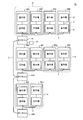
- FIG. 1 is a block diagram illustrating an example of a configuration of an air conditioning control system 1 according to the first embodiment.
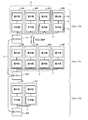
- FIG. 2 is a block diagram illustrating another example of the configuration of the air conditioning control system 1 according to the first embodiment.
- connection lines indicating the control relationships of the respective parts are illustrated.
- the air conditioning control system 1 includes one main remote controller device (hereinafter referred to as “main remote control device”) 10 and one or more sub remote controller devices (hereinafter referred to as “sub remote control devices”). 20) and a plurality of air conditioners 30.
- the air conditioning control system 1 includes one main remote control device 10, two slave remote control devices 20A and 20B, and ten air conditioners 30A to 30J.
- each air conditioner 30 belongs to one of the plurality of groups.
- One of the main remote control device 10 and the sub remote control device 20 is provided in association with each group. Normally, the operation of the air conditioners 30 belonging to each group is controlled by the associated main remote controller 10 or the sub remote controller 20.
- the air conditioning control system 1 includes three groups X, Y, and Z.
- the group X includes four air conditioners 30A to 30D, and these air conditioners 30A to 30D are controlled by the main remote controller 10.
- the group Y includes four air conditioners 30E to 30H, and these air conditioners 30E to 30H are controlled by the slave remote controller 20A.
- Two air conditioners 30I and 30J belong to the group Z, and these air conditioners 30I and 30J are controlled by the slave remote controller 20B.
- the slave remote control devices 20A and 20B will be simply referred to as “slave remote control device 20” when it is not necessary to distinguish between them. Further, when there is no need to particularly distinguish the air conditioners 30A to 30J, the air conditioners 30A to 30J will be simply referred to as “air conditioner 30”.
- the main remote control device 10 is for controlling operations such as operation mode setting, temperature setting, and air volume setting in the air conditioner 30, for example.
- the main remote controller 10 controls the operation of the air conditioner 30 belonging to a predetermined group among a plurality of groups formed in the air conditioning control system 1.
- the main remote controller 10 is connected to the air conditioners 30A to 30D belonging to the group X via the connection line 3, and controls the operation of the air conditioners 30A to 30D.
- the main remote control device 10 is connected to slave remote control devices 20A and 20B, which will be described later, by a connection line 2.
- the main remote controller 10 receives, for example, information related to the air conditioners 30E to 30H connected to the slave remote controller 20A via the connection line 2. Then, by controlling the connected slave remote controller 20A based on the received information, the master remote controller 10 controls the operation of the air conditioners 30E to 30H belonging to the group Y controlled by the slave remote controller 20A. Can do.
- the main remote controller 10 receives, for example, information related to the air conditioners 30I and 30J connected to the slave remote controller 20B via the connection line 2. Then, by controlling the connected slave remote controller 20B based on the received information, the master remote controller 10 controls the operations of the air conditioners 30I and 30J belonging to the group Z controlled by the slave remote controller 20B. Can do.
- the sub remote controller 20 is for controlling operations such as operation mode setting, temperature setting, air volume setting, etc. in the air conditioner 30.
- the sub remote control device 20 controls the operation of the air conditioner 30 belonging to a predetermined predetermined group among a plurality of groups formed in the air conditioning control system 1.
- the slave remote controller 20A is connected to the air conditioners 30E to 30H belonging to the group Y via the connection line 3, and controls the operation of the air conditioners 30E to 30H.
- the slave remote controller 20B is connected to the air conditioners 30I and 30J belonging to the group Z via the connection line 3, and controls the operation of the air conditioners 30I and 30J.
- the slave remote controller 20A transmits information related to the air conditioners 30E to 30H belonging to the group Y to the main remote controller 10 via the connection line 2. Then, the slave remote controller 20A controls the operations of the air conditioners 30E to 30H belonging to the group Y by the control of the main remote controller 10 based on the transmitted information.
- the sub remote control device 20B transmits information on the air conditioners 30I and 30J belonging to the group Z to the main remote control device 10 via the connection line 2. Then, the slave remote controller 20B controls the operation of the air conditioners 30I and 30J belonging to the group Z by the control of the main remote controller 10 based on the transmitted information.
- the air conditioner 30 includes an indoor unit 31 and an outdoor unit 32.
- the indoor unit 31 is configured to include a use-side heat exchanger (not shown), and performs heat exchange between the indoor air and the refrigerant to cool the indoor air during cooling operation, During the heating operation, heating is performed by heating the room air.
- the outdoor unit 32 includes a heat source side heat exchanger (not shown), performs heat exchange between the outdoor air and the refrigerant, and condenses the refrigerant by radiating the heat of the refrigerant to the outdoor air during the cooling operation. In addition, during the heating operation, the refrigerant is evaporated, and the outdoor air is cooled by the heat of vaporization.
- the indoor unit 31 and the outdoor unit 32 are connected by a connection line 4.
- the indoor unit 31 controls the operation of the outdoor unit 32 via the connection line 4 based on the control of the main remote controller 10 or the slave remote controller 20.
- one indoor unit 31 is connected to one outdoor unit 32, but the present invention is not limited to this, and a plurality of indoor units 31 are connected to one outdoor unit 32. May be connected.
- the main remote control device 10 and the sub remote control devices 20A and 20B are connected by a connection line 2 and communicate using a first communication method to be described later. Specifically, the main remote control device 10 is connected to the slave remote control device 20A by the connection line 2, and the slave remote control device 20A is connected to the slave remote control device 20B by the connection line 2.
- the main remote control device 10 and the sub remote control device 20 are connected to the air conditioner 30 belonging to the group controlled by the connection device 3 by a crossover wiring, using a second communication method different from the first communication method. Communication takes place.
- the main remote controller 10 is connected to the air conditioners 30A to 30D belonging to the group X by the connection line 3. Specifically, the main remote control device 10 is connected to the air conditioner 30A via the connection line 3, and the air conditioners 30A to 30D are connected via the connection line 3 to the air conditioner 30A, the air conditioner 30B, the air conditioner 30C, They are connected in the order of the air conditioner 30D.
- the slave remote controller 20A is connected to the air conditioners 30E to 30H belonging to the group Y by the connection line 3.
- the slave remote controller 20A is connected to the air conditioner 30E via the connection line 3, and the air conditioners 30E to 30H are connected via the connection line 3 to the air conditioner 30E, the air conditioner 30F, the air conditioner 30G, The air conditioner 30H is connected in this order.
- the sub remote controller 20B is connected to the air conditioners 30I and 30J belonging to the group Z by the connection line 3.
- the slave remote controller 20B is connected to the air conditioner 30I via the connection line 3, and the air conditioner 30I is connected to the air conditioner 30J via the connection line 3.
- the indoor unit 31 and the outdoor unit 32 are connected by the connection line 4, and communication is performed using a third communication method described later.
- the third communication method for example, a communication method described in Japanese Patent No. 2948502 or a general-purpose multi-drop method such as RS-485 which is a communication standard of EIA (Electronic Industries Association) A communication method can be used.
- a communication method for example, a case where the AC power line and the connection line 4 configured by one communication line are used, and a communication line using a dedicated line different from the AC power line and the AC power line are used.
- a connection line 4 composed of two lines is used.
- the former connection line 4 can be easily constructed as compared with the latter connection line 4, the communication distance is short and the communication speed is low. Therefore, the maximum number of indoor units 31 that can be connected to one outdoor unit 32 is, for example, four.
- the case where the former connection line 4 is used will be described as an example.
- Communication between the main remote control device 10, the sub remote control devices 20A and 20B, and the air conditioner 30 through the connection line 3 is performed using the second communication method.
- the number of indoor units 31 that can be connected to one outdoor unit 32 is restricted by the third communication method, so that the main remote control device 10 and the sub remote control devices 20A and 20B can be connected.
- the number of indoor units 31 is also limited to four.
- the communication method described in Japanese Patent No. 2948502 described above is applied as the third communication method, one indoor unit according to the number of indoor units 31 connected to one outdoor unit 32. This is because the amount of current supplied to 31 is reduced, and bit determination of communication data becomes difficult.
- the four indoor units 31 are assumed to perform the same control for the operation mode setting, temperature setting, air volume setting, and the like. That is, the indoor units 31 of the air conditioners 30 belonging to the same group are controlled so as to operate in the same manner by the main remote controller 10 or the sub remote controller 20.
- the first communication method is, for example, a wireless communication method such as BLE (Bluetooth (registered trademark) Low Energy) which is short-range wireless communication, and wirelessly communicates between the main remote control device 10 and the slave remote control devices 20A and 20B. Can be connected with.
- BLE Bluetooth (registered trademark) Low Energy) which is short-range wireless communication
- BLE Bluetooth (registered trademark) Low Energy
- BLE Bluetooth (registered trademark) Low Energy) which is short-range wireless communication
- the wireless communication method as the first communication method in this way, for example, as shown in FIG. 2, it is connected to a portable terminal 40 such as a smartphone or a tablet, or connected to a temperature / humidity sensor 41. Connection with equipment is also possible. Further, when connected to the mobile terminal 40, the main remote control device 10 can be remotely operated from the mobile terminal 40. This eliminates the need for the user to move directly to the installation location of main remote control device 10 for operation.
- the air conditioner 30 that can be controlled by the main remote control device 10 by performing communication according to the first communication method between the main remote control device 10 and the sub remote control device 20. Can be substantially increased.
- the sub remote control device 20 functions as a relay device that relays communication with the main remote control device 10 according to the first communication method and communication with the air conditioner 30 according to the second communication method.
- a plurality of sub remote control devices 20 can be connected to the main remote control device 10, and the air conditioner 30 connected to the main remote control device 10 and the sub remote control device 20 is based on the control of the main remote control device 10. Operate.
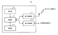
- FIG. 3 is a block diagram showing an example of the configuration of the main remote controller 10 shown in FIG.
- the main remote controller 10 includes a first communication unit 11, a second communication unit 12, a storage unit 13, an operation unit 14, and a control unit 15.
- the first communication unit 11 communicates with the slave remote control device 20 according to a predetermined communication protocol using a wireless communication method that is a first communication method. For example, the first communication unit 11 receives information on the indoor units 31 of the air conditioners 30E to 30J connected to the slave remote controller 20 from each slave remote controller 20 connected to the master remote controller 10. . The first communication unit 11 supplies the received information regarding the indoor unit 31 to the control unit 15. In addition, the first communication unit 11 performs the operation mode setting and temperature setting received from the control unit 15 for each slave remote control device 20 connected to the main remote control device 10 based on control by the control unit 15 described later. , Setting information including various setting contents such as air volume setting is transmitted.
- the second communication unit 12 communicates with the air conditioners 30A to 30D in the group X to which the main remote controller 10 belongs, using the second communication method and according to a predetermined communication protocol. For example, the second communication unit 12 transmits the setting information supplied from the control unit 15 to the air conditioners 30A to 30D in the group X based on the control by the control unit 15. The second communication unit 12 receives information related to the indoor unit 31 from the air conditioning apparatuses 30A to 30D and supplies the information to the control unit 15.
- the storage unit 13 has various types such as the number of sub remote control devices 20 connected to the main remote control device 10 and the number of air conditioners 30 connected to the main remote control device 10 and the sub remote control device 20. Store information.
- the operation unit 14 includes keys for performing various settings such as operation mode setting, temperature setting, air volume setting, etc. of the air conditioner 30, or an operator for operation by a user such as a touch panel stacked on a display unit (not shown). Is provided. When an operation is performed by the user, the operation unit 14 generates a control signal corresponding to the operation and supplies the control signal to the control unit 15.
- the control unit 15 controls the operation of each unit in the main remote controller 10.
- the control unit 15 is configured by software executed on an arithmetic device such as a microcomputer or a CPU (Central Processing Unit).
- the control unit 15 determines the air conditioner 30 to be operated based on the control signal supplied from the operation unit 14 and controls the operation state of the air conditioner 30 provided in the air conditioning control system 1. Generate configuration information.
- the control part 15 supplies this setting information to the 1st communication part 11, in order to transmit setting information with respect to the slave remote control apparatus 20 corresponding to the air conditioning apparatus 30 to operate
- the control unit 15 is based on the information regarding the indoor unit 31 received via the first communication unit 11 and the second communication unit 12, and the air conditioner 30 connected to the main remote control device 10 and the sub remote control device 20. Is generated and stored in the storage unit 13.
- the slave remote control device 20 corresponding to the added air conditioning device 30 is connected to the main remote control device 10 via the connection line 2. Connecting. Thereby, the main remote control device 10 is connected to the sub remote control device 20 using the first communication method, and can control the operation of the air conditioner 30 connected to the added sub remote control device 20.
- the number of slave remote control devices 20 connectable to the main remote control device 10 depends on the communication protocol of the first communication method. In this example, for example, 64 slave remote control devices 20 can be connected.
- the number of air conditioners 30 connectable to one slave remote controller 20 is limited to four in this example as described above. Therefore, the maximum number of air conditioners 30 that can be controlled by the main remote controller 10 is 256.
- the main remote control device 10 and the sub remote control device 20 are connected by the first communication method using the connection line 2, and the main remote control device 10 is connected to the sub remote control device 20.
- the air conditioner 30 can be controlled. Therefore, even when the number of air conditioners 30 that can be controlled by one remote controller such as the main remote controller 10 is limited, the number of controllable air conditioners 30 can be substantially increased. That is, when the whole system is considered, the number of air conditioners 30 that can be controlled by one remote control device can be increased. Since the air conditioner 30 can be added by connecting the main remote controller 10 and the slave remote controller 20 in this way, the air conditioning system does not have a mechanism for connecting the air conditioner via a common bus. However, it is possible to easily add an air conditioner.
- the main remote controller 10 is configured to be able to communicate with the slave remote controller 20 using the first communication method, the air conditioner 30 that can be controlled by one remote controller while maintaining the conventional system. The number of can be increased.
- Embodiment 2 an air conditioning control system according to the second embodiment will be described.
- the operation of the air conditioner in the system is controlled so that the COP (Coefficient Of Performance) indicating the energy consumption efficiency in the entire system operates at the maximum.
- COP Coefficient Of Performance
- FIG. 4 is a block diagram showing an example of the configuration of the air conditioning control system 50 according to the second embodiment.
- the air conditioning control system 50 includes a temperature sensor 51 in addition to the configuration of the air conditioning control system 1 according to the first embodiment described above.
- This temperature sensor 51 is provided in the vicinity of the installation position of the indoor unit 31 of the main remote controller 10 or the air conditioner 30. In this example, it is assumed that the temperature sensor 51 is provided in the vicinity of the main remote controller 10.
- the temperature sensor 51 detects the temperature of the installed space and supplies temperature information indicating the detection result to the main remote controller 10.
- the main remote controller 10 calculates the temperature difference between the temperature of the space indicated by the temperature information supplied from the temperature sensor 51 and the set temperature set in the main remote controller 10. Then, the main remote controller 10 calculates the number of air conditioners 30 to be operated so that the COP in the entire system is maximized and the operating capacity of the air conditioner 30 based on the calculated temperature difference. Based on the calculation result, the main remote controller 10 controls the target air conditioner 30 in the system to operate with the calculated driving ability.
- the main remote controller 10 calculates, in the control unit 15 shown in FIG. 3, the number of air conditioners 30 to be operated and the operating capacity so that the COP in the entire system described above is maximized.
- the control unit 15 calculates a temperature difference based on the set temperature and the temperature information from the temperature sensor 51. Based on the calculated temperature difference and the information indicating the number of slave remote controllers 20 and the number of indoor units 31 in the system stored in the storage unit 13, the control unit 15 has the maximum COP of the air conditioner 30. Calculate the number and driving capacity. And the control part 15 determines the air conditioning apparatus 30 to operate
- the indoor units 31 to be operated are randomly changed, and all the indoor units 31 are It is preferable to switch at regular intervals. This is to make the temperature in the same space uniform.
- the main remote controller 10 controls the air conditioners 30A and 30B surrounded by a preset dotted line P to operate with 80% capacity.
- the main remote controller 10 controls the air conditioners 30G and 30H surrounded by the dotted line Q via the slave remote controller 20A so as to operate with the same ability.
- the main remote controller 10 controls the air conditioners 30I and 30J surrounded by the dotted line R via the slave remote controller 20B so as to operate with the same ability.
- the air conditioner 30 to be operated is changed every predetermined time for all the air conditioners 30 connected to the main remote controller 10 and the sub remote controller 20.
- control that maximizes the COP can be performed for a larger number of air conditioners 30 than in the past.
- control can be performed so that the COP is maximized only with respect to four air conditioners with one remote control device, but according to the second embodiment.
- the above-described control can be performed for five or more air conditioners 30.
- control part 15 determined the number and operating capability of the air conditioning apparatus 30 to operate
- the control unit 15 presets the number of air conditioners 30 to be operated so that the driving ability always becomes a certain value or more, and controls the COP to be maximized in the set number of air conditioners 30. You may do it. Thereby, the comfort in space can be maintained.
- Embodiment 3 An air conditioning control system according to Embodiment 3 will be described.
- an air conditioner that periodically repeats operation and operation stop is set, and control is performed so as to perform a so-called rotation operation in which the set air conditioner is operated alternately.
- the same parts as those in the first and second embodiments are denoted by the same reference numerals, and detailed description thereof is omitted.
- FIG. 5 is a block diagram showing an example of the configuration of the air conditioning control system 1 according to the third embodiment.
- the configuration of the air conditioning control system 1 according to Embodiment 3 is the same as that of the air conditioning control system 1 according to Embodiment 1 described above.
- the air conditioners 30A to 30C surrounded by the dotted line S and the air conditioners 30E to 30G surrounded by the dotted line T are set in advance so as to repeat the operation and the operation stop periodically.
- the air conditioner 30 is shown.
- the air conditioner 30 that periodically repeats operation and operation stop is set, for example, when the user operates the main remote controller 10. For example, the user selects a predetermined number of air conditioners for each group from among the air conditioners 30 belonging to the group controlled by the main remote controller 10 and the air conditioners 30 belonging to the group controlled by the slave remote controllers 20A and 20B. The device 30 is selected. When the air conditioner 30 is selected in this way, the main remote controller 10 selects the selected air conditioner using the slave remote controller 20 corresponding to the group to which the selected air conditioner 30 belongs as a relay device. 30 is controlled to operate in order.
- three air conditioners 30A to 30C belonging to a group X surrounded by a dotted line S and three air conditioners 30E to 30G belonging to a group Y surrounded by a dotted line T Consider the case where is selected.
- the main remote controller 10 first controls the air conditioners 30A to 30C belonging to the group X to operate.
- the main remote controller 10 performs control via the slave remote controller 20A so that the air conditioners 30E to 30G belonging to the group Y are operated after the air conditioners 30A to 30C are stopped.
- main remote controller 10 controls air conditioners 30A to 30C and air conditioners 30E to 30G so as to sequentially repeat this operation.
- a predetermined number of air conditioners 30 selected for each group are sequentially operated from all the air conditioners 30 connected to the main remote controller 10 and the sub remote controller 20.
- the rotation operation could not be performed only between the air conditioners that can be controlled by one remote control device, whereas each of the main remote control device 10 and the sub remote control device 20 can be controlled. Rotation operation can be performed between the various air conditioners 30.
- the rotation operation is described as being performed between two groups.
- the rotation operation is not limited to this, and the rotation operation may be performed between three or more groups.
- the main remote controller 10 may set an operation schedule for operating the air conditioner 30 for each slave remote controller 20. Accordingly, the slave remote controller 20 can operate autonomously according to the set operation schedule, and can drive the corresponding air conditioner 30.
- Embodiment 4 an air conditioning control system according to the fourth embodiment will be described.
- frost may adhere to the outdoor unit, and therefore, a defrost operation for removing the attached frost may be performed.
- a defrost operation for removing the attached frost may be performed.
- a plurality of air conditioners having the same operation capability are installed in an equivalent environment and the heating operation is performed, there is a possibility that the defrost operation is simultaneously started in the plurality of air conditioners.
- the defrost operation does not overlap in all the air conditioners. Control the operation of the air conditioner.
- the same parts as those in Embodiments 1 to 3 are denoted by the same reference numerals, and detailed description thereof is omitted.
- the control unit 15 of the main remote controller 10 predicts the defrost start time indicating the time when each air conditioner 30 starts the defrost operation and the defrost duration indicating the duration of the defrost operation. To do. And the control part 15 controls the heating operation capability in each air conditioning apparatus 30 so that the defrost start time and defrost continuation time do not correspond between the some air conditioning apparatuses 30.
- the control unit 15 of the main remote controller 10 calculates the defrost start time and the defrost duration based on the suction temperature of the indoor unit 31 of each air conditioner 30.
- control unit 15 determines whether there is an air conditioner 30 that simultaneously starts the defrost operation. Moreover, the control part 15 judges whether the air conditioning apparatus 30 with which defrost continuation time corresponds exists based on the calculated defrost continuation time.
- the control unit 15 adjusts the heating operation capacity of the corresponding air conditioner 30. And the control part 15 is controlled to perform the rotation operation
- the control part 15 estimates the defrost start time and defrost continuation time in all the air conditioning apparatuses 30 in a system, and the heating operation capability of the air conditioning apparatus 30 according to a prediction result. adjust. Thereby, while being able to reduce that the several air conditioning apparatus 30 starts a defrost driving
- the operation of the air conditioner 30 is controlled so that the defrost operation is not started simultaneously in all the air conditioners 30. be able to.
- the second communication method that is the communication method between the remote control device such as the slave remote control device 20 and the indoor unit 31 of the air conditioner 30 is the same communication method.
- a different communication system may be sufficient.
- a gateway function or a bridge function is provided for the remote control device.
- the remote control device converts the communication data format received by the first communication method into a data format suitable for the air conditioner 30 that is the control target.
- the air-conditioning system comprised as a different system can be integrated in the air-conditioning control system which concerns on this invention, and it can make it cooperate with a remote control apparatus.
- Air-conditioning control system 2 3, 4, connection line, 10 main remote controller device, 11 first communication unit, 12 second communication unit, 13 storage unit, 14 operation unit, 15 control unit, 20, 20A , 20B slave remote controller device, 30, 30A-30J air conditioner, 31 indoor unit, 32 outdoor unit, 40 portable terminal, 41 temperature / humidity sensor, 51 temperature sensor.
Landscapes
- Engineering & Computer Science (AREA)
- Chemical & Material Sciences (AREA)
- Combustion & Propulsion (AREA)
- Mechanical Engineering (AREA)
- General Engineering & Computer Science (AREA)
- Human Computer Interaction (AREA)
- Physics & Mathematics (AREA)
- Fuzzy Systems (AREA)
- Mathematical Physics (AREA)
- Signal Processing (AREA)
- Air Conditioning Control Device (AREA)
Abstract
Description
これにより、空調システム内に複数の制御装置が接続されている場合でも、容易かつ効率的に仮想制御部を生成することができる。 Further, some conventional air conditioning systems are provided with a control device for each of a plurality of air conditioners constituting the system (see, for example, Patent Document 1). When a plurality of control devices are connected in the system as in the air conditioning system described in
Thereby, even when a plurality of control devices are connected in the air conditioning system, a virtual control unit can be generated easily and efficiently.
以下、本発明の実施の形態1に係る空調制御システムについて説明する。
この空調制御システムは、複数の空気調和装置の動作をリモートコントローラによって制御するものである。各空気調和装置は、複数に形成されたグループのうちいずれかのグループに属し、それぞれのグループ毎に対応付けられたリモートコントローラにより、その動作が制御される。
Hereinafter, the air conditioning control system according to
This air conditioning control system controls operation of a plurality of air conditioners by a remote controller. Each air conditioner belongs to one of a plurality of groups, and its operation is controlled by a remote controller associated with each group.
図1は、本実施の形態1に係る空調制御システム1の構成の一例を示すブロック図である。図2は、本実施の形態1に係る空調制御システム1の構成の他の例を示すブロック図である。
なお、以下の説明で参照する図においては、各部の制御関係を示す接続線のみが図示されているものとする。 [Configuration of air conditioning control system]
FIG. 1 is a block diagram illustrating an example of a configuration of an air
In the drawings referred to in the following description, only the connection lines indicating the control relationships of the respective parts are illustrated.
グループXには、4台の空気調和装置30A~30Dが属し、これらの空気調和装置30A~30Dは、主リモコン装置10によって制御される。グループYには、4台の空気調和装置30E~30Hが属し、これらの空気調和装置30E~30Hは、従リモコン装置20Aによって制御される。グループZには、2台の空気調和装置30Iおよび30Jが属し、これらの空気調和装置30Iおよび30Jは、従リモコン装置20Bによって制御される。
なお、以下の説明において、従リモコン装置20Aおよび20Bを特に区別する必要がない場合には、単に「従リモコン装置20」と称して説明する。また、空気調和装置30A~30Jを特に区別する必要がない場合には、単に「空気調和装置30」と称して説明する。 In the example illustrated in FIG. 1, the air
The group X includes four
In the following description, the slave
主リモコン装置10は、例えば、空気調和装置30における運転モード設定、温度設定、風量設定等の動作を制御するためのものである。主リモコン装置10は、空調制御システム1内に形成された複数のグループのうち、対応付けられた所定のグループに属する空気調和装置30の動作を制御する。
この例において、主リモコン装置10は、グループXに属する空気調和装置30A~30Dと接続線3で接続され、空気調和装置30A~30Dの動作を制御する。 (Main remote control device)
The main
In this example, the main
主リモコン装置10は、例えば、従リモコン装置20Aに接続された空気調和装置30E~30Hに関する情報を、接続線2を介して受信する。そして、受信した情報に基づき、接続された従リモコン装置20Aを制御することにより、主リモコン装置10は、従リモコン装置20Aが制御するグループYに属する空気調和装置30E~30Hの動作を制御することができる。
主リモコン装置10は、例えば、従リモコン装置20Bに接続された空気調和装置30Iおよび30Jに関する情報を、接続線2を介して受信する。そして、受信した情報に基づき、接続された従リモコン装置20Bを制御することにより、主リモコン装置10は、従リモコン装置20Bが制御するグループZに属する空気調和装置30Iおよび30Jの動作を制御することができる。 The main
The main
The main
従リモコン装置20は、例えば、空気調和装置30における運転モード設定、温度設定、風量設定等の動作を制御するためのものである。従リモコン装置20は、空調制御システム1内に形成された複数のグループのうち、対応付けられた所定のグループに属する空気調和装置30の動作を制御する。
この例において、従リモコン装置20Aは、グループYに属する空気調和装置30E~30Hと接続線3で接続され、空気調和装置30E~30Hの動作を制御する。また、従リモコン装置20Bは、グループZに属する空気調和装置30Iおよび30Jと接続線3で接続され、空気調和装置30Iおよび30Jの動作を制御する。 (Sub remote control device)
The sub remote controller 20 is for controlling operations such as operation mode setting, temperature setting, air volume setting, etc. in the air conditioner 30. The sub remote control device 20 controls the operation of the air conditioner 30 belonging to a predetermined predetermined group among a plurality of groups formed in the air
In this example, the
従リモコン装置20Bは、グループZに属する空気調和装置30Iおよび30Jに関する情報を、接続線2を介して主リモコン装置10に送信する。そして、送信した情報に基づく主リモコン装置10の制御により、従リモコン装置20Bは、グループZに属する空気調和装置30Iおよび30Jの動作を制御する。 The
The sub
空気調和装置30は、室内機31および室外機32を備える。
室内機31は、図示しない利用側熱交換器を含んで構成され、室内空気と冷媒との間で熱交換を行うことにより、冷房運転の際に、室内空気を冷却して冷房を行うとともに、暖房運転の際に、室内空気を加熱して暖房を行う。
室外機32は、図示しない熱源側熱交換器を含んで構成され、室外空気と冷媒との間で熱交換を行い、冷房運転の際に、冷媒の熱を室外空気に放熱して冷媒を凝縮させるとともに、暖房運転の際に、冷媒を蒸発させ、その際の気化熱により室外空気を冷却する。 (Air conditioner)
The air conditioner 30 includes an
The
The
なお、図1に示す例では、1台の室外機32に対して1台の室内機31が接続されているが、これに限らず、1台の室外機32に対して複数の室内機31が接続されてもよい。 The
In the example shown in FIG. 1, one
次に、空調制御システム1を構成する主リモコン装置10、従リモコン装置20Aおよび20B、ならびに空気調和装置30の接続関係について説明する。 [Connections of each part]
Next, the connection relationship between the main
主リモコン装置10は、グループXに属する空気調和装置30A~30Dと、接続線3によって接続される。具体的には、主リモコン装置10は、接続線3によって空気調和装置30Aに接続され、空気調和装置30A~30Dは、接続線3によって空気調和装置30A、空気調和装置30B、空気調和装置30C、空気調和装置30Dの順に接続される。
従リモコン装置20Aは、グループYに属する空気調和装置30E~30Hと、接続線3によって接続される。具体的には、従リモコン装置20Aは、接続線3によって空気調和装置30Eに接続され、空気調和装置30E~30Hは、接続線3によって空気調和装置30E、空気調和装置30F、空気調和装置30G、空気調和装置30Hの順に接続される。
従リモコン装置20Bは、グループZに属する空気調和装置30Iおよび30Jと、接続線3によって接続される。具体的には、従リモコン装置20Bは、接続線3によって空気調和装置30Iに接続され、空気調和装置30Iは、接続線3によって空気調和装置30Jに接続される。 The main
The main
The slave
The sub
次に、各接続線2~4に接続された装置間の通信方式について説明する。 [Communication method between devices]
Next, a communication system between devices connected to the
第3の通信方式は、例えば、AC電源線および通信線が1本の線で構成された接続線4を用いる場合と、AC電源線、およびAC電源線とは異なる別の専用線による通信線の2本の線で構成された接続線4を用いる場合とがある。
前者の接続線4は、後者の接続線4と比較して、容易に施工できるものの、通信距離が短く、通信速度も遅い。そのため、1台の室外機32に接続可能な室内機31の数は、例えば最大で4台となる。ここでは、前者の接続線4を用いる場合を例にとって説明する。 Communication between the
In the third communication method, for example, a case where the AC power line and the
Although the
第2の通信方式は、第3の通信方式によって1台の室外機32に接続可能な室内機31の台数が制約されることから、主リモコン装置10、従リモコン装置20Aおよび20Bが接続可能な室内機31の台数も4台に制限される。これは、例えば第3の通信方式として上述した特許第2948502号公報に記載の通信方式を適用した場合、1台の室外機32に接続される室内機31の台数に応じて1台の室内機31に供給される電流量が減少し、通信データのビット判定が困難となるためである。
また、4台の室内機31は、運転モード設定、温度設定、および風量設定等について、同様の制御が行われるものとする。
すなわち、同一グループに属する空気調和装置30の室内機31は、主リモコン装置10または従リモコン装置20によって同様に動作するように制御される。 Communication between the main
In the second communication method, the number of
The four
That is, the
第1の通信方式は、例えば、近距離無線通信であるBLE(Bluetooth(登録商標) Low Energy)等の無線通信方式であり、主リモコン装置10と、従リモコン装置20Aおよび20Bとの間を無線で接続することができる。このように、近距離無線通信方式を用いることにより、室内機31から主リモコン装置10、従リモコン装置20Aおよび20Bへの給電能力を低減することができる。 Communication between the main
The first communication method is, for example, a wireless communication method such as BLE (Bluetooth (registered trademark) Low Energy) which is short-range wireless communication, and wirelessly communicates between the main
また、従リモコン装置20は、第1の通信方式による主リモコン装置10との通信と、第2の通信方式による空気調和装置30との間の通信とを中継する中継装置として機能する。
主リモコン装置10に対しては、複数の従リモコン装置20を接続することができ、主リモコン装置10および従リモコン装置20に接続された空気調和装置30は、主リモコン装置10の制御に基づいて動作する。 In the air
The sub remote control device 20 functions as a relay device that relays communication with the main
A plurality of sub remote control devices 20 can be connected to the main
次に、主リモコン装置10の構成について説明する。
図3は、図1に示す主リモコン装置10の構成の一例を示すブロック図である。
図3に示すように、主リモコン装置10は、第1の通信部11、第2の通信部12、記憶部13、操作部14および制御部15を備えている。 [Configuration of main remote control unit]
Next, the configuration of the main
FIG. 3 is a block diagram showing an example of the configuration of the main
As shown in FIG. 3, the main
例えば、第1の通信部11は、主リモコン装置10に接続されたそれぞれの従リモコン装置20から、当該従リモコン装置20に接続された空気調和装置30E~30Jの室内機31に関する情報を受信する。第1の通信部11は、受信した室内機31に関する情報を制御部15に供給する。
また、第1の通信部11は、後述する制御部15による制御に基づき、主リモコン装置10に接続されたそれぞれの従リモコン装置20に対して、制御部15から受け取った運転モード設定、温度設定、風量設定等の各種設定内容を含む設定情報を送信する。 The first communication unit 11 communicates with the slave remote control device 20 according to a predetermined communication protocol using a wireless communication method that is a first communication method.
For example, the first communication unit 11 receives information on the
In addition, the first communication unit 11 performs the operation mode setting and temperature setting received from the
例えば、第2の通信部12は、制御部15による制御に基づき、グループX内の空気調和装置30A~30Dに対して、制御部15から供給された設定情報を送信する。
また、第2の通信部12は、空気調和装置30A~30Dから室内機31に関する情報を受信し、制御部15に供給する。 The
For example, the
The
制御部15は、操作部14から供給された制御信号に基づき、動作させる空気調和装置30を決定するとともに、この空調制御システム1内に設けられた空気調和装置30の運転状態を制御するための設定情報を生成する。そして、制御部15は、動作させる空気調和装置30に対応する従リモコン装置20に対して設定情報を送信するため、この設定情報を第1の通信部11に供給する。
また、制御部15は、第1の通信部11および第2の通信部12を介して受信した室内機31に関する情報に基づき、主リモコン装置10および従リモコン装置20に接続された空気調和装置30の台数を示す情報を生成し、記憶部13に記憶する。 The
The
In addition, the
図1に示す空調制御システム1に対して、空気調和装置30を増設する場合には、増設する空気調和装置30に対応する従リモコン装置20を主リモコン装置10に対して接続線2を介して接続する。これにより、主リモコン装置10は、従リモコン装置20と第1の通信方式を用いて接続され、増設された従リモコン装置20に接続された空気調和装置30の動作を制御することができる。 [Addition of air conditioner to air conditioning control system]
When the air conditioning device 30 is added to the air
従って、主リモコン装置10で制御可能な空気調和装置30の台数は、最大で256台となる。 Here, the number of slave remote control devices 20 connectable to the main
Therefore, the maximum number of air conditioners 30 that can be controlled by the main
そして、このように主リモコン装置10と従リモコン装置20とを接続することにより、空気調和装置30を増設できるので、共通バスを介して空気調和装置を接続する仕組みを持たない空調システムであっても、空気調和装置を容易に増設することができる。 As described above, in the first embodiment, the main
Since the air conditioner 30 can be added by connecting the main
次に、本実施の形態2に係る空調制御システムについて説明する。
本実施の形態2に係る空調制御システムでは、システム全体におけるエネルギー消費効率を示すCOP(Coefficient Of Performance;成績係数)が最大で動作するように、システム内の空気調和装置の動作を制御する。
なお、以下の説明において、実施の形態1と同様の部分には同一の符号を付し、詳細な説明を省略する。
Next, an air conditioning control system according to the second embodiment will be described.
In the air conditioning control system according to the second embodiment, the operation of the air conditioner in the system is controlled so that the COP (Coefficient Of Performance) indicating the energy consumption efficiency in the entire system operates at the maximum.
In the following description, the same parts as those in the first embodiment are denoted by the same reference numerals, and detailed description thereof is omitted.
図4は、本実施の形態2に係る空調制御システム50の構成の一例を示すブロック図である。
図4に示すように、空調制御システム50は、上述した実施の形態1に係る空調制御システム1の構成に加えて、温度センサ51を備えている。この温度センサ51は、主リモコン装置10または空気調和装置30の室内機31の設置位置の近傍に設けられている。この例において、温度センサ51は、主リモコン装置10の近傍に設けられているものとする。
温度センサ51は、設置された空間の温度を検出し、検出結果を示す温度情報を主リモコン装置10に供給する。 [Configuration of air conditioning control system]
FIG. 4 is a block diagram showing an example of the configuration of the air
As shown in FIG. 4, the air
The
主リモコン装置10は、図3に示す制御部15において、上述したシステム全体におけるCOPが最大となるように、動作させる空気調和装置30の台数および運転能力を算出する。
制御部15は、設定温度と温度センサ51からの温度情報とに基づき温度差を算出する。制御部15は、算出した温度差と、記憶部13に記憶された従リモコン装置20の台数およびシステム中の室内機31の台数を示す情報とに基づき、COPが最大となる空気調和装置30の台数および運転能力を算出する。そして、制御部15は、算出結果に基づき、動作させる空気調和装置30を決定する。 [Configuration of main remote control unit]
The main
The
主リモコン装置10が、2台の室内機31を80%の能力で運転することによってCOPが最大となると算出した場合には、予め設定された2台の室内機31を80%の能力で動作させる。 For example, consider an air
When the main
具体的には、例えば、従来は1台のリモコン装置で4台の空気調和装置に対してのみ、COPが最大となる制御を行うことができたのに対して、本実施の形態2に係る空調制御システム50では、5台以上の空気調和装置30を対象として上述した制御を行うことができる。 As described above, in the second embodiment, the air conditioner 30 to be operated is changed every predetermined time for all the air conditioners 30 connected to the main
Specifically, for example, control can be performed so that the COP is maximized only with respect to four air conditioners with one remote control device, but according to the second embodiment. In the air
例えば、制御部15は、運転能力が常に一定値以上となるように動作させる空気調和装置30の台数を予め設定し、設定された台数の空気調和装置30でCOPが最大となるように制御するようにしてもよい。これにより、空間内における快適性を維持することができる。 In addition, although the
For example, the
次に、本実施の形態3に係る空調制御システムについて説明する。
本実施の形態3に係る空調制御システムでは、運転および運転停止を周期的に繰り返す空気調和装置を設定し、設定された空気調和装置を交互に動作させる、所謂ローテーション動作を行うように制御する。
なお、以下の説明において、実施の形態1および2と同様の部分には同一の符号を付し、詳細な説明を省略する。
Next, an air conditioning control system according to
In the air conditioning control system according to the third embodiment, an air conditioner that periodically repeats operation and operation stop is set, and control is performed so as to perform a so-called rotation operation in which the set air conditioner is operated alternately.
In the following description, the same parts as those in the first and second embodiments are denoted by the same reference numerals, and detailed description thereof is omitted.
図5は、本実施の形態3に係る空調制御システム1の構成の一例を示すブロック図である。
本実施の形態3に係る空調制御システム1の構成は、上述した実施の形態1に係る空調制御システム1と同様である。
図5に示す例において、点線Sで囲まれた空気調和装置30A~30C、および点線Tで囲まれた空気調和装置30E~30Gは、運転および運転停止を周期的に繰り返すように予め設定された空気調和装置30であることを示す。 [Configuration of air conditioning control system]
FIG. 5 is a block diagram showing an example of the configuration of the air
The configuration of the air
In the example shown in FIG. 5, the
ユーザは、例えば、主リモコン装置10が制御するグループに属する空気調和装置30と、従リモコン装置20Aおよび20Bが制御するグループに属する空気調和装置30との中から、グループ毎に所定台数の空気調和装置30を選択する。そして、このようにして空気調和装置30が選択されると、主リモコン装置10は、選択された空気調和装置30が属するグループに対応する従リモコン装置20を中継装置として、選択された空気調和装置30を順番に動作させるように設定して制御する。 The air conditioner 30 that periodically repeats operation and operation stop is set, for example, when the user operates the main
For example, the user selects a predetermined number of air conditioners for each group from among the air conditioners 30 belonging to the group controlled by the main
この場合、主リモコン装置10は、まず、グループXに属する空気調和装置30A~30Cが運転動作するように制御する。次に、主リモコン装置10は、空気調和装置30A~30Cが運転停止した後、グループYに属する空気調和装置30E~30Gが運転動作するように、従リモコン装置20Aを介して制御する。そして、主リモコン装置10は、この動作を順次繰り返すように、空気調和装置30A~30Cおよび空気調和装置30E~30Gを制御する。 For example, as shown in FIG. 5, three
In this case, the main
次に、本実施の形態4に係る空調制御システムについて説明する。
一般に、空気調和装置において暖房運転を継続している場合には、室外機に霜が付着することがあるため、付着した霜を取り除くためのデフロスト運転を行うことがある。また、同等の運転能力を有する複数の空気調和装置を同等の環境下に設置して暖房運転を行う場合には、複数の空気調和装置において同時にデフロスト運転を開始してしまう可能性がある。
Next, an air conditioning control system according to the fourth embodiment will be described.
Generally, when the heating operation is continued in the air conditioner, frost may adhere to the outdoor unit, and therefore, a defrost operation for removing the attached frost may be performed. In addition, when a plurality of air conditioners having the same operation capability are installed in an equivalent environment and the heating operation is performed, there is a possibility that the defrost operation is simultaneously started in the plurality of air conditioners.
なお、以下の説明において、実施の形態1~3と同様の部分には同一の符号を付し、詳細な説明を省略する。 Therefore, in the air conditioning control system according to the fourth embodiment, even in the air conditioning control system in which a plurality of groups are formed during the heating operation, the defrost operation does not overlap in all the air conditioners. Control the operation of the air conditioner.
In the following description, the same parts as those in
また、制御部15は、算出したデフロスト継続時間に基づき、デフロスト継続時間が一致する空気調和装置30が存在するか否かを判断する。 Based on the defrost start time calculated for each air conditioner 30, the
Moreover, the
この場合には、例えば、リモコン装置に対してゲートウェイ機能またはブリッジ機能を設ける。リモコン装置は、第1の通信方式によって受信した通信データ形式を、制御対象である空気調和装置30に適したデータ形式に変換する。これにより、異なるシステムとして構成されていた空調システムを本発明に係る空調制御システムに組み込み、リモコン装置によって連携させることができる。 For example, in the first to fourth embodiments, the second communication method that is the communication method between the remote control device such as the slave remote control device 20 and the
In this case, for example, a gateway function or a bridge function is provided for the remote control device. The remote control device converts the communication data format received by the first communication method into a data format suitable for the air conditioner 30 that is the control target. Thereby, the air-conditioning system comprised as a different system can be integrated in the air-conditioning control system which concerns on this invention, and it can make it cooperate with a remote control apparatus.
Claims (8)
- 室内機および室外機を有する複数の空気調和装置と、
前記複数の空気調和装置のうち一部の空気調和装置に対応付けられ、該空気調和装置の動作を制御する主リモコン装置と、
前記主リモコン装置と第1の通信方式を用いて接続されるとともに、前記複数の空気調和装置のうちその他の空気調和装置に対応付けられ、該空気調和装置の動作を制御する1または複数の従リモコン装置と
を備え、
前記空気調和装置の室内機は、
前記主リモコン装置および前記従リモコン装置のうち、対応付けられたリモコン装置と前記第1の通信方式とは異なる第2の通信方式を用いて接続され、
前記主リモコン装置は、
前記従リモコン装置を介して前記その他の空気調和装置の動作を制御する
空調制御システム。 A plurality of air conditioners having an indoor unit and an outdoor unit;
A main remote controller that is associated with some of the plurality of air conditioners and controls the operation of the air conditioner;
One or more slaves that are connected to the main remote controller using the first communication method and that are associated with other air conditioners among the plurality of air conditioners and control the operation of the air conditioners. A remote control device,
The indoor unit of the air conditioner is
Of the main remote control device and the slave remote control device, the associated remote control device is connected using a second communication method different from the first communication method,
The main remote control device
An air conditioning control system for controlling the operation of the other air conditioner via the slave remote controller. - 前記主リモコン装置および前記室内機の少なくとも一方が設置された位置の温度を検出する温度センサをさらに備え、
前記主リモコン装置は、
前記室内機に関する情報を受信する通信部と、
前記室内機に関する情報を記憶する記憶部と、
ユーザによる操作に基づき、前記複数の空気調和装置のうち、動作させる空気調和装置を決定する制御部と
を有し、
前記制御部は、
前記空気調和装置に対して設定された設定温度と、前記温度センサで検出された温度との温度差を算出し、
算出した前記温度差および前記室内機に関する情報に基づき、成績係数が最大となる空気調和装置の台数および運転能力を算出し、
前記算出結果に基づき、前記動作させる空気調和装置を決定する
請求項1に記載の空調制御システム。 A temperature sensor for detecting a temperature at a position where at least one of the main remote controller and the indoor unit is installed;
The main remote control device
A communication unit for receiving information on the indoor unit;
A storage unit for storing information about the indoor unit;
A control unit that determines an air conditioner to be operated among the plurality of air conditioners based on an operation by a user;
The controller is
Calculating a temperature difference between a set temperature set for the air conditioner and a temperature detected by the temperature sensor;
Based on the calculated temperature difference and information on the indoor unit, calculate the number of air conditioners and the operating capacity with the highest coefficient of performance,
The air conditioning control system according to claim 1, wherein the air conditioner to be operated is determined based on the calculation result. - 前記制御部は、
動作させる前記空気調和装置を、所定時間経過毎に変更するように制御する
請求項2に記載の空調制御システム。 The controller is
The air conditioning control system according to claim 2, wherein the air conditioner to be operated is controlled to change every predetermined time. - 前記主リモコン装置は、
該主リモコン装置に対応付けられた前記空気調和装置と、前記従リモコン装置に対応付けられた前記空気調和装置とのそれぞれの中から、運転および運転停止を周期的に繰り返す空気調和装置を選択し、
選択されたそれぞれの前記空気調和装置のうちいずれかが順番に運転するように、選択された前記空気調和装置の動作を制御する
請求項1~3のいずれか一項に記載の空調制御システム。 The main remote control device
An air conditioner that periodically repeats operation and shutdown is selected from each of the air conditioner associated with the main remote controller and the air conditioner associated with the slave remote controller. ,
The air conditioning control system according to any one of claims 1 to 3, wherein an operation of the selected air conditioner is controlled so that any one of the selected air conditioners operates in order. - 前記主リモコン装置は、
それぞれの前記室内機の吸込温度に基づき、それぞれの前記空気調和装置におけるデフロスト運転の開始時間と、前記デフロスト運転の継続時間とを算出し、
算出された前記開始時間および前記継続時間に基づき、前記複数の空気調和装置において前記デフロスト運転が重ならないように、前記空気調和装置の動作を制御する
請求項1~4のいずれか一項に記載の空調制御システム。 The main remote control device
Based on the suction temperature of each indoor unit, the start time of the defrost operation in each air conditioner, and the duration of the defrost operation are calculated,
The operation of the air conditioner is controlled based on the calculated start time and the duration time so that the defrost operations do not overlap in the plurality of air conditioners. Air conditioning control system. - 前記第1の通信方式は、
無線通信方式である
請求項1~5のいずれか一項に記載の空調制御システム。 The first communication method is:
The air conditioning control system according to any one of claims 1 to 5, which is a wireless communication system. - 前記従リモコン装置のうち少なくとも1つは、
ゲートウェイ機能およびブリッジ機能のうち少なくとも一方を有し、
前記ゲートウェイ機能および前記ブリッジ機能のうち少なくとも一方を有する前記従リモコン装置は、
前記第1の通信方式および前記第2の通信方式とは異なる通信方式を用いて前記空気調和装置の前記室内機と接続される
請求項1~6のいずれか一項に記載の空調制御システム。 At least one of the slave remote control devices is
Having at least one of a gateway function and a bridge function;
The slave remote controller having at least one of the gateway function and the bridge function is:
The air conditioning control system according to any one of claims 1 to 6, wherein the air conditioning control system is connected to the indoor unit of the air conditioner using a communication method different from the first communication method and the second communication method. - 室内機および室外機を有する1または複数の空気調和装置に対応付けられ、該空気調和装置の動作を制御するリモコン装置であって、
他の空気調和装置に対応付けられた他のリモコン装置が第1の通信方式を用いて接続され、
対応付けられた前記空気調和装置の室内機と前記第1の通信方式とは異なる第2の通信方式を用いて接続され、
前記他のリモコン装置を介して前記他の空気調和装置の動作を制御する
リモコン装置。 A remote control device that is associated with one or more air conditioners having an indoor unit and an outdoor unit and controls the operation of the air conditioner,
Other remote control devices associated with other air conditioning devices are connected using the first communication method,
The associated indoor unit of the air conditioner is connected using a second communication method different from the first communication method,
A remote control device that controls the operation of the other air conditioner via the other remote control device.
Priority Applications (6)
| Application Number | Priority Date | Filing Date | Title |
|---|---|---|---|
| JP2017566485A JP6632637B2 (en) | 2016-02-12 | 2016-02-12 | Air conditioning control system |
| AU2016392133A AU2016392133B2 (en) | 2016-02-12 | 2016-02-12 | Air-conditioning control system and remote control device |
| US16/060,503 US10697659B2 (en) | 2016-02-12 | 2016-02-12 | Air-conditioning control system and remote control device |
| EP16889843.5A EP3415830B1 (en) | 2016-02-12 | 2016-02-12 | Air-conditioning control system and remote control device |
| PCT/JP2016/054098 WO2017138141A1 (en) | 2016-02-12 | 2016-02-12 | Air-conditioning control system and remote control device |
| CN201680081131.4A CN108700322B (en) | 2016-02-12 | 2016-02-12 | Air conditioner control system and remote control device |
Applications Claiming Priority (1)
| Application Number | Priority Date | Filing Date | Title |
|---|---|---|---|
| PCT/JP2016/054098 WO2017138141A1 (en) | 2016-02-12 | 2016-02-12 | Air-conditioning control system and remote control device |
Publications (1)
| Publication Number | Publication Date |
|---|---|
| WO2017138141A1 true WO2017138141A1 (en) | 2017-08-17 |
Family
ID=59562945
Family Applications (1)
| Application Number | Title | Priority Date | Filing Date |
|---|---|---|---|
| PCT/JP2016/054098 WO2017138141A1 (en) | 2016-02-12 | 2016-02-12 | Air-conditioning control system and remote control device |
Country Status (6)
| Country | Link |
|---|---|
| US (1) | US10697659B2 (en) |
| EP (1) | EP3415830B1 (en) |
| JP (1) | JP6632637B2 (en) |
| CN (1) | CN108700322B (en) |
| AU (1) | AU2016392133B2 (en) |
| WO (1) | WO2017138141A1 (en) |
Cited By (2)
| Publication number | Priority date | Publication date | Assignee | Title |
|---|---|---|---|---|
| WO2020245891A1 (en) * | 2019-06-03 | 2020-12-10 | 三菱電機株式会社 | Remote controller and air-conditioning system |
| WO2020261553A1 (en) * | 2019-06-28 | 2020-12-30 | 三菱電機株式会社 | Remote controller and air-conditioning system |
Families Citing this family (7)
| Publication number | Priority date | Publication date | Assignee | Title |
|---|---|---|---|---|
| CN108332366B (en) * | 2017-01-17 | 2021-08-20 | 松下知识产权经营株式会社 | Air conditioner control device and air conditioner control method |
| DE102017117130A1 (en) * | 2017-07-28 | 2019-01-31 | Ebm-Papst Mulfingen Gmbh & Co. Kg | wireless transmission |
| KR102393277B1 (en) * | 2017-08-24 | 2022-05-03 | 삼성전자주식회사 | Air-conditioner repeater, air-conditioner system and the control method thereof |
| CN108302742B (en) * | 2018-04-13 | 2020-05-29 | 珠海格力电器股份有限公司 | Controller of air conditioning unit and air conditioner |
| JP7057531B2 (en) * | 2018-06-13 | 2022-04-20 | ダイキン工業株式会社 | Air conditioning system |
| CN112484238B (en) * | 2020-11-16 | 2021-11-23 | 珠海格力电器股份有限公司 | Defrosting control method and device, multi-module unit and heating and ventilation equipment |
| CN113815661B (en) * | 2021-09-03 | 2023-01-24 | 新誉轨道交通科技有限公司 | Train air conditioner control system and control method thereof |
Citations (11)
| Publication number | Priority date | Publication date | Assignee | Title |
|---|---|---|---|---|
| JPS62131135A (en) * | 1985-12-04 | 1987-06-13 | Matsushita Refrig Co | Air conditioner |
| JPH03217750A (en) * | 1990-01-22 | 1991-09-25 | Daikin Ind Ltd | Operation controller for air-conditioner |
| JPH05288392A (en) * | 1992-04-03 | 1993-11-02 | Matsushita Seiko Co Ltd | Controller for air conditioner |
| JP2948502B2 (en) | 1995-03-30 | 1999-09-13 | 三菱電機株式会社 | Operation control device for multi-type air conditioner |
| JP2005300016A (en) * | 2004-04-12 | 2005-10-27 | Hitachi Ltd | Air conditioning system |
| JP2013104645A (en) * | 2011-11-16 | 2013-05-30 | Fujitsu General Ltd | Air conditioner and remote controller |
| JP2013113445A (en) * | 2011-11-25 | 2013-06-10 | Mitsubishi Electric Corp | Air conditioner |
| JP2013137189A (en) * | 2013-02-25 | 2013-07-11 | Mitsubishi Electric Corp | Air conditioning system |
| JP2013160477A (en) * | 2012-02-07 | 2013-08-19 | Mitsubishi Heavy Ind Ltd | Air conditioning system |
| JP2013221676A (en) * | 2012-04-16 | 2013-10-28 | Mitsubishi Electric Corp | Controller, and cold heat apparatus system with the controller |
| JP2015141014A (en) | 2014-01-30 | 2015-08-03 | 三菱重工業株式会社 | Air conditioning system and control method of the same |
Family Cites Families (13)
| Publication number | Priority date | Publication date | Assignee | Title |
|---|---|---|---|---|
| JPH05296546A (en) * | 1992-04-15 | 1993-11-09 | Toshiba Corp | Air conditioning system |
| SG69967A1 (en) * | 1993-04-28 | 2000-01-25 | Daikin Ind Ltd | Driving control device for air conditioner |
| JP3378781B2 (en) * | 1997-09-03 | 2003-02-17 | 三洋電機株式会社 | Air conditioner |
| JP2001208406A (en) | 2000-01-31 | 2001-08-03 | Sanyo Electric Co Ltd | Controller for air conditioner system |
| JP2002228236A (en) | 2001-01-29 | 2002-08-14 | Matsushita Electric Ind Co Ltd | Centralized control device for electric equipment and air conditioners |
| KR100629345B1 (en) * | 2005-02-24 | 2006-09-29 | 엘지전자 주식회사 | Multi-Air Conditioner central control system |
| US7983796B2 (en) * | 2006-09-21 | 2011-07-19 | Kassel Edward A | Energy efficient method of monitoring and controlling an HVAC system |
| JP2009210161A (en) * | 2008-02-29 | 2009-09-17 | Sanyo Electric Co Ltd | Equipment control system, control device, and control program |
| JP5312055B2 (en) | 2009-01-07 | 2013-10-09 | 三菱電機株式会社 | Air conditioning system |
| US9494952B2 (en) * | 2011-03-31 | 2016-11-15 | Trane International Inc. | Systems and methods for controlling multiple HVAC systems |
| US9450408B2 (en) * | 2011-10-07 | 2016-09-20 | Siemens Corporation | Adaptive demand response based on distributed load control |
| KR101964626B1 (en) * | 2012-01-16 | 2019-04-02 | 엘지전자 주식회사 | Air conditioner and method for distributing addresses of the same |
| CN103854457A (en) * | 2012-11-30 | 2014-06-11 | 广东美的制冷设备有限公司 | Master-slave remote controller system, control method and air conditioner |
-
2016
- 2016-02-12 US US16/060,503 patent/US10697659B2/en active Active
- 2016-02-12 AU AU2016392133A patent/AU2016392133B2/en active Active
- 2016-02-12 WO PCT/JP2016/054098 patent/WO2017138141A1/en active Application Filing
- 2016-02-12 EP EP16889843.5A patent/EP3415830B1/en active Active
- 2016-02-12 JP JP2017566485A patent/JP6632637B2/en active Active
- 2016-02-12 CN CN201680081131.4A patent/CN108700322B/en active Active
Patent Citations (11)
| Publication number | Priority date | Publication date | Assignee | Title |
|---|---|---|---|---|
| JPS62131135A (en) * | 1985-12-04 | 1987-06-13 | Matsushita Refrig Co | Air conditioner |
| JPH03217750A (en) * | 1990-01-22 | 1991-09-25 | Daikin Ind Ltd | Operation controller for air-conditioner |
| JPH05288392A (en) * | 1992-04-03 | 1993-11-02 | Matsushita Seiko Co Ltd | Controller for air conditioner |
| JP2948502B2 (en) | 1995-03-30 | 1999-09-13 | 三菱電機株式会社 | Operation control device for multi-type air conditioner |
| JP2005300016A (en) * | 2004-04-12 | 2005-10-27 | Hitachi Ltd | Air conditioning system |
| JP2013104645A (en) * | 2011-11-16 | 2013-05-30 | Fujitsu General Ltd | Air conditioner and remote controller |
| JP2013113445A (en) * | 2011-11-25 | 2013-06-10 | Mitsubishi Electric Corp | Air conditioner |
| JP2013160477A (en) * | 2012-02-07 | 2013-08-19 | Mitsubishi Heavy Ind Ltd | Air conditioning system |
| JP2013221676A (en) * | 2012-04-16 | 2013-10-28 | Mitsubishi Electric Corp | Controller, and cold heat apparatus system with the controller |
| JP2013137189A (en) * | 2013-02-25 | 2013-07-11 | Mitsubishi Electric Corp | Air conditioning system |
| JP2015141014A (en) | 2014-01-30 | 2015-08-03 | 三菱重工業株式会社 | Air conditioning system and control method of the same |
Cited By (8)
| Publication number | Priority date | Publication date | Assignee | Title |
|---|---|---|---|---|
| WO2020245891A1 (en) * | 2019-06-03 | 2020-12-10 | 三菱電機株式会社 | Remote controller and air-conditioning system |
| JPWO2020245891A1 (en) * | 2019-06-03 | 2021-12-02 | 三菱電機株式会社 | Remote controller and air conditioning system |
| GB2596980A (en) * | 2019-06-03 | 2022-01-12 | Mitsubishi Electric Corp | Remote controller and air-conditioning system |
| JP7112167B2 (en) | 2019-06-03 | 2022-08-03 | 三菱電機株式会社 | Remote controller and air conditioning system |
| GB2596980B (en) * | 2019-06-03 | 2023-02-08 | Mitsubishi Electric Corp | Remote controller and air-conditioning system |
| WO2020261553A1 (en) * | 2019-06-28 | 2020-12-30 | 三菱電機株式会社 | Remote controller and air-conditioning system |
| JPWO2020261553A1 (en) * | 2019-06-28 | 2021-11-25 | 三菱電機株式会社 | Remote controller and air conditioning system |
| JP7134352B2 (en) | 2019-06-28 | 2022-09-09 | 三菱電機株式会社 | Remote controller and air conditioning system |
Also Published As
| Publication number | Publication date |
|---|---|
| US10697659B2 (en) | 2020-06-30 |
| EP3415830B1 (en) | 2021-01-06 |
| CN108700322B (en) | 2020-08-25 |
| US20180356115A1 (en) | 2018-12-13 |
| AU2016392133A1 (en) | 2018-07-26 |
| CN108700322A (en) | 2018-10-23 |
| EP3415830A4 (en) | 2019-02-20 |
| JP6632637B2 (en) | 2020-01-22 |
| EP3415830A1 (en) | 2018-12-19 |
| JPWO2017138141A1 (en) | 2018-09-20 |
| AU2016392133B2 (en) | 2019-08-15 |
Similar Documents
| Publication | Publication Date | Title |
|---|---|---|
| WO2017138141A1 (en) | Air-conditioning control system and remote control device | |
| JP4699722B2 (en) | Central control system for multi air conditioner and its operation method | |
| US9121624B2 (en) | Information transfer system for refrigeration air-conditioning apparatus | |
| EP1610069B1 (en) | Air conditioning system and method for controlling the same | |
| CN108496043B (en) | Air-conditioning device | |
| KR20100012660A (en) | Air conditioner and controlling method for the same | |
| KR20090082727A (en) | Device controlling system and emergency controlling method thereof | |
| KR101962628B1 (en) | Multi type air conditioner and controlling method for the same | |
| KR101573363B1 (en) | Air-conditioner and method | |
| KR101860920B1 (en) | Air conditioner and method | |
| JP5646303B2 (en) | Air conditioner | |
| KR20120033747A (en) | Air conditioner and method | |
| KR101225976B1 (en) | Air conditioner and the controlling method | |
| JP4849256B2 (en) | Integrated current control system for air conditioners | |
| KR20080059909A (en) | Multi air conditioner | |
| WO2017149750A1 (en) | Air-conditioning system | |
| KR20220095970A (en) | Air conditioner and method for operating the same | |
| CN114484788A (en) | Recording medium, air conditioning apparatus, and air conditioning method | |
| KR20120098196A (en) | Air conditioner and method | |
| KR100743715B1 (en) | Air conditioning system | |
| KR20210092623A (en) | Central control device and air conditioner including the same | |
| KR20220011976A (en) | Electronic device and air conditioner including the same | |
| KR20150091917A (en) | Air-conditioner and method | |
| KR20120090275A (en) | Air conditioner and method | |
| JP2018189278A (en) | Air conditioner, control method for air conditioner and control program for air conditioner |
Legal Events
| Date | Code | Title | Description |
|---|---|---|---|
| 121 | Ep: the epo has been informed by wipo that ep was designated in this application |
Ref document number: 16889843 Country of ref document: EP Kind code of ref document: A1 |
|
| ENP | Entry into the national phase |
Ref document number: 2017566485 Country of ref document: JP Kind code of ref document: A |
|
| ENP | Entry into the national phase |
Ref document number: 2016392133 Country of ref document: AU Date of ref document: 20160212 Kind code of ref document: A |
|
| NENP | Non-entry into the national phase |
Ref country code: DE |
|
| WWE | Wipo information: entry into national phase |
Ref document number: 2016889843 Country of ref document: EP |
|
| ENP | Entry into the national phase |
Ref document number: 2016889843 Country of ref document: EP Effective date: 20180912 |