WO2017138105A1 - Manipulator system - Google Patents
Manipulator system Download PDFInfo
- Publication number
- WO2017138105A1 WO2017138105A1 PCT/JP2016/053937 JP2016053937W WO2017138105A1 WO 2017138105 A1 WO2017138105 A1 WO 2017138105A1 JP 2016053937 W JP2016053937 W JP 2016053937W WO 2017138105 A1 WO2017138105 A1 WO 2017138105A1
- Authority
- WO
- WIPO (PCT)
- Prior art keywords
- manipulator
- unit
- movement amount
- outer sheath
- guide member
- Prior art date
Links
Images


Classifications
-
- A—HUMAN NECESSITIES
- A61—MEDICAL OR VETERINARY SCIENCE; HYGIENE
- A61B—DIAGNOSIS; SURGERY; IDENTIFICATION
- A61B34/00—Computer-aided surgery; Manipulators or robots specially adapted for use in surgery
- A61B34/30—Surgical robots
-
- A—HUMAN NECESSITIES
- A61—MEDICAL OR VETERINARY SCIENCE; HYGIENE
- A61B—DIAGNOSIS; SURGERY; IDENTIFICATION
- A61B34/00—Computer-aided surgery; Manipulators or robots specially adapted for use in surgery
- A61B34/70—Manipulators specially adapted for use in surgery
- A61B34/74—Manipulators with manual electric input means
-
- A—HUMAN NECESSITIES
- A61—MEDICAL OR VETERINARY SCIENCE; HYGIENE
- A61B—DIAGNOSIS; SURGERY; IDENTIFICATION
- A61B34/00—Computer-aided surgery; Manipulators or robots specially adapted for use in surgery
- A61B34/20—Surgical navigation systems; Devices for tracking or guiding surgical instruments, e.g. for frameless stereotaxis
- A61B2034/2046—Tracking techniques
- A61B2034/2059—Mechanical position encoders
-
- A—HUMAN NECESSITIES
- A61—MEDICAL OR VETERINARY SCIENCE; HYGIENE
- A61B—DIAGNOSIS; SURGERY; IDENTIFICATION
- A61B34/00—Computer-aided surgery; Manipulators or robots specially adapted for use in surgery
- A61B34/20—Surgical navigation systems; Devices for tracking or guiding surgical instruments, e.g. for frameless stereotaxis
- A61B2034/2046—Tracking techniques
- A61B2034/2061—Tracking techniques using shape-sensors, e.g. fiber shape sensors with Bragg gratings
-
- A—HUMAN NECESSITIES
- A61—MEDICAL OR VETERINARY SCIENCE; HYGIENE
- A61B—DIAGNOSIS; SURGERY; IDENTIFICATION
- A61B34/00—Computer-aided surgery; Manipulators or robots specially adapted for use in surgery
- A61B34/30—Surgical robots
- A61B2034/301—Surgical robots for introducing or steering flexible instruments inserted into the body, e.g. catheters or endoscopes
-
- A—HUMAN NECESSITIES
- A61—MEDICAL OR VETERINARY SCIENCE; HYGIENE
- A61B—DIAGNOSIS; SURGERY; IDENTIFICATION
- A61B90/00—Instruments, implements or accessories specially adapted for surgery or diagnosis and not covered by any of the groups A61B1/00 - A61B50/00, e.g. for luxation treatment or for protecting wound edges
- A61B90/06—Measuring instruments not otherwise provided for
- A61B2090/061—Measuring instruments not otherwise provided for for measuring dimensions, e.g. length
-
- A—HUMAN NECESSITIES
- A61—MEDICAL OR VETERINARY SCIENCE; HYGIENE
- A61B—DIAGNOSIS; SURGERY; IDENTIFICATION
- A61B90/00—Instruments, implements or accessories specially adapted for surgery or diagnosis and not covered by any of the groups A61B1/00 - A61B50/00, e.g. for luxation treatment or for protecting wound edges
- A61B90/06—Measuring instruments not otherwise provided for
- A61B2090/067—Measuring instruments not otherwise provided for for measuring angles
Definitions
- the present invention relates to a manipulator system.
- the elongated multi-lumen tube has a flexible multi-lumen tube whose outer periphery is covered with a coil tube, and the wire is passed through the lumen formed in the multi-lumen tube. The torque is transmitted by the coil tube.
- JP 2014-23721 A Japanese Patent No. 5550150
- the present invention has been made in view of the above-described circumstances, and bends without excessively increasing the tension acting on the power transmission member penetrating the lumen, and appropriately operates the movable portion according to the bending form.
- An object of the present invention is to provide a manipulator system that can be made to operate.
- One aspect of the present invention includes a manipulator, an operation unit that performs an input for operating the manipulator, and a control unit that controls the manipulator based on an input to the operation unit, and the manipulator includes a movable unit.
- a drive unit that generates power to be supplied to the movable unit, a long and thin long guide member that attaches the movable unit to one end and the drive unit to the other end, and transmits the power of the drive unit to the movable unit
- the elongated guide member is more rigid than the guide tube covering the outer periphery of the guide tube and the elongated flexible guide tube having a lumen that penetrates the power transmission member in the longitudinal direction.
- Control unit is a manipulator system for changing control parameters in accordance with the amount of movement of the outer sheath.
- the control unit controls the manipulator based on the input to the operation unit, and the manipulator is activated.
- the power generated in the drive unit by the operation of the drive unit is transmitted to the movable unit via the power transmission member, and the movable unit is operated.
- the guide tube and the outer sheath constituting the long guide member are bent and the lumen provided in the guide tube is also bent, so that the power transmission member is guided in the curved lumen. Power will be transmitted. Further, the torque around the longitudinal axis applied on the drive part side can be transmitted to the movable part by the outer sheath having higher rigidity than the guide tube.
- the length dimension of the highly rigid outer sheath disposed at the innermost innermost portion of the curve does not change.
- the dimension of the elongated guide member after bending is determined by the innermost diameter part, and the outer side in the radial direction of the curve than the innermost diameter part.
- the amount of compression of the innermost diameter portion is compensated by the amount of movement of the outer sheath by moving the proximal end of the outer sheath in the longitudinal direction of the guide tube with respect to the drive unit before and after the bending of the long guide member. It is possible to suppress the extension of the guide tube and suppress the path length variation of the power transmission member. Thus, the long guide member can be bent while preventing an excessive change in the tension of the power transmission member accompanying the change in the path length.
- the amount of movement of the proximal end of the outer sheath relative to the drive unit is proportional to the total bending angle of the long guide member.
- the frictional force between the power transmission member brought into contact with the inner wall of the lumen and the lumen is determined by the total bending angle of the long guide member. Therefore, by changing the control parameter according to the amount of movement of the outer sheath, it is possible to appropriately control the manipulator in consideration of the frictional force between the lumen and the power transmission member.
- the base end of the said guide tube may be attached with respect to the said drive part so that a movement in the longitudinal direction of the said elongate guide member is possible.
- the compression amount of the innermost diameter portion can be reduced by moving the long guide member in the longitudinal direction of the guide tube with respect to the drive unit.
- the amount of movement of the outer sheath can be compensated, and the driving force can be stably transmitted by suppressing the extension of the guide tube due to friction with the wire passing through the outer sheath.
- a long guide member can be curved, suppressing instability of power transmission by wire drive.
- a movement amount display unit that displays the movement amount of the outer sheath
- a movement amount input unit that inputs the movement amount of the outer sheath, the movement that is input from the movement amount input unit.
- the control parameter may be changed according to the amount. In this way, when the long guide member is bent, the proximal end of the outer sheath moves with respect to the drive unit, and the movement amount is displayed by the movement amount display unit.
- the control unit changes the control parameter according to the input movement amount, so that the lumen, the power transmission member, The manipulator can be appropriately controlled in consideration of the frictional force between the two.
- the movement amount detection part which detects the movement amount of the said outer sheath may be provided, and the said control part may change the said control parameter according to the movement amount detected by the said movement amount detection part.
- the control unit changes the control parameter according to the detected movement amount, so that the manipulator can be appropriately controlled in consideration of the frictional force between the lumen and the power transmission member.
- the said outer sheath may be provided so that a movement with respect to the said drive part is provided, and the lock mechanism which fixes the said outer sheath and the said drive part in arbitrary relative positions may be provided.
- the manipulator is inserted into a curved endoscope channel by inserting it into a body cavity, for example, and the long guide member is curved in accordance with the shape of the endoscope channel.
- the shape of the long guide member does not change greatly. For this reason, when the long guide member is curved, the proximal end of the outer sheath moves in a direction approaching the drive unit disposed on the proximal end side.
- the relative position between the outer sheath and the drive unit is locked by the operation of the locking mechanism.
- the guide tube is covered with the outer sheath having higher rigidity for a longer time, and the compressive force applied to the guide tube can be received by the outer sheath when the movable portion is driven by the drive portion.
- rumen may have the shape twisted around the longitudinal axis of the said guide tube.
- the shape of the lumen is changed along with the bending, but the inner surface of the lumen having a shape twisted around the longitudinal axis of the guide tube and the inside of the lumen are changed.
- the contact state with the driving force transmission member passing therethrough does not change greatly depending on the bending state of the insertion portion.
- the insertion portion can be bent without excessively increasing the tension acting on the power transmission member penetrated through the lumen, and the movable portion can be appropriately operated according to the bending form. .
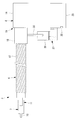
- the manipulator system 1 includes a master device (operation unit) 2 operated by an operator A, a manipulator 3 inserted into a body cavity of a patient P, A control unit 4 that controls the manipulator 3 based on an operation input to the master device 2, an input unit (movement amount input unit) 20, and a storage unit 30 are provided.
- reference numeral 5 denotes a monitor for displaying an endoscopic image or the like.
- the manipulator 3 includes, for example, an elongated flexible long guide member 6 that is inserted into the body cavity of the patient P through a channel of the endoscope 12 that is inserted into the body cavity of the patient P.
- a movable portion 7 disposed at the distal end of the long guide member 6; a drive portion 8 disposed at the proximal end of the long guide member 6 and operated by the control portion 4 to operate the movable portion 7;
- Wires (power transmission members) 9 a and 9 b for transmitting the driving force generated by the driving unit 8 to the movable unit 7 are provided.
- the movable part 7 includes a treatment part 10 such as forceps that acts on an affected part in the body, and at least one joint part 11 that supports the treatment part 10.
- the joint portion 11 has a single swing joint that swings the treatment portion 10 about an axis perpendicular to the longitudinal axis of the long guide member 6. Show.
- the driving unit 8 includes a pulley 13 connected to a motor (not shown) that generates a driving force, and a housing 14 that rotatably supports the pulley 13.
- Two wires 9a and 9b are wound around the pulley 13, and when the pulley 13 is rotated by the operation of the motor, any of the wires 9a and 9b wound around the pulley 13 is rotated in the rotation direction of the pulley 13.
- the joint portion 11 is driven in either direction by the tension transmitted by the wires 9a and 9b.
- the long guide member 6 includes a multi-lumen tube (guide tube) 16 having two lumens 15 a and 15 b that penetrates the two wires 9 a and 9 b, and an outer peripheral surface of the multi-lumen tube 16.
- a coil tube (outer sheath) 17 disposed so as to be covered and a slider 18 fixed to the base end of the coil tube 17 are provided.
- the multi-lumen tube 16 is made of a soft resin material that is easily deformed and has low rigidity.
- the coil tube 17 is made of a metal material having higher rigidity than the multi-lumen tube 16. As shown in FIG. 2A, the coil tube 17 is a close-contact coil that closely contacts the strands with the long guide member 6 extended linearly.
- the distal end of the multi-lumen tube 16 is fixed to the joint portion 11, and the base end of the multi-lumen tube 16 is fixed to the housing 14 of the drive unit 8.
- the tip of the coil tube 17 is also fixed to the joint portion 11.
- the slider 18 is provided so as to be movable in the longitudinal direction of the multi-lumen tube 16 with respect to the housing 14 of the drive unit 8.
- the base end of the coil tube 17 is supported so as to be movable in the longitudinal direction of the multi-lumen tube 16. That is, a guide mechanism 19 that supports the base end of the coil tube 17 so as to be movable in the longitudinal direction of the multi-lumen tube 16 is configured by the housing 14 and the slider 18 of the drive unit 8.
- a gap is formed in the longitudinal direction of the multi-lumen tube 16 between the slider 18 and the housing 14 of the drive unit 8 in a state where the long guide member 6 is linearly extended. Has been.
- the slider 18 is provided with a scale (movement amount display unit) 21.
- a scale movement amount display unit 21.
- the slider 18 moves, the slider 18 is accommodated in the housing 14, so that the scales 21 provided on the slider 18 are sequentially hidden. Therefore, the amount of movement of the slider 18 can be read by reading the scale 21 at a position that coincides with the end face of the housing 14.
- the input unit 20 is a device in which an operator who has read the scale 21 inputs the read movement amount, and any input device such as a mouse or a keyboard can be employed.
- the storage unit 30 stores the movement amount and the control parameter in association with each other.
- the control parameter is a coefficient for calculating the driving force generated by the driving unit 8 of the manipulator 3 with respect to the operation input input by the master device 2.
- the relationship between the moving amount of the slider 18 and the shape of the long guide member 6 will be described.
- the highly flexible multi-lumen tube 16 disposed along the center is curved. Since both ends of the multi-lumen tube 16 are fixed to the movable portion 7 and the drive portion 8, if the multi-lumen tube 16 is bent without extending or contracting its length along the center line, the multi-lumen tube 16 is formed.
- the lumens 15a and 15b are not greatly expanded and contracted, and the path lengths of the wires 9a and 9b disposed in the lumens 15a and 15b do not vary greatly.
- the coil tube 17 covering the outer periphery thereof is also bent. Since the coil tube 17 is made of a material having sufficiently high rigidity with respect to the multi-lumen tube 16, when the long guide member 6 is bent, the length of the portion arranged on the inner diameter side of the curve is long. The length does not change while the strands are kept in close contact with each other, and is curved so as to widen the spacing between the strands arranged on the outer diameter side of the curvature.
- the proximal end of the coil tube 17 is movable in the longitudinal direction of the multi-lumen tube 16 with respect to the housing 14 of the drive unit 8. It is fixed to the slider 18. Therefore, when the long guide member 6 is bent, the slider 18 moves with respect to the housing 14 and moves the proximal end of the coil tube 17 to the drive unit 8 side.
- the length of the coil tube 17 disposed on the inner diameter side of the curve does not vary before and after the bending, but the proximal end of the coil tube 17 is not fixed, so the proximal end of the coil tube 17 is the slider 18 and the housing. 14 so as to close the gap with respect to 14.
- the long guide member 6 is curved in two directions. Since the inner diameter side dimension of the bending of the coil tube 17 does not change before and after the bending, the lengths are set to the lengths L1 and L2 in the first bending portion and the second bending portion, respectively. The angles of the second curved portions are assumed to be angles ⁇ 1 and ⁇ 2, respectively.
- the radius from the central axis of the long guide member 6 to the center position of the wire constituting the coil tube 17 is a radius r
- the long guide member 6 in the first curved portion and the second curved portion Are lengths L1 + r ⁇ 1 and L2 + r ⁇ 2, respectively.
- the movement amount of the slider 18 is a value obtained by multiplying the total bending angle of the long guide member 6 by the radius r. Since the radius r is a constant, the total bending angle of the long guide member 6 can be obtained from the amount of movement of the slider 18. This is not limited to the case where there are two curved portions, but can be applied to a plurality of arbitrary cases. That is, the total bending angle ⁇ flex is expressed by Equation 1.
- the frictional force applied to the wires 9a and 9b can be calculated only by the total bending angle ⁇ flex without being related to the curvature radius, the bending direction, and the bending angle of each curved portion of the long guide member 6. Therefore, it is possible to uniquely obtain a control parameter for appropriately controlling the movable portion 7 from the movement amount of the slider 18.
- the manipulator 3 according to the present embodiment is provided via the channel of the insertion part of the endoscope 12 inserted from outside the body of the patient P into the body cavity.
- the movable portion 7 is inserted from the movable portion 7 side of the distal end, and the movable portion 7 is projected from the opening of the forceps channel on the distal end surface of the insertion portion of the endoscope 12 disposed in the body.
- the body cavity is often winding, and the insertion portion of the endoscope 12 and the channel provided in the insertion portion are bent following the shape of the body cavity and inserted into the body cavity. Therefore, when the manipulator 3 is inserted through such a channel, the manipulator 3 is inserted while the long guide member 6 is curved in accordance with the channel.
- the slider 18 moves with respect to the housing 14 and moves the proximal end of the coil tube 17 to the drive unit 8 side. That is, the length of the coil tube 17 disposed on the inner diameter side of the curve does not vary before and after the bending, but the proximal end of the coil tube 17 is not fixed, so the proximal end of the coil tube 17 is the slider 18 and the housing. 14 so as to close the gap with 14. As a result, the tension of the multi-lumen tube 16 is prevented from increasing, the length of the multi-lumen tube 16 is maintained, and the path length of the wire 9a is prevented from extending.
- the control unit 4 stores the control parameter stored in the storage unit 30 in association with the movement amount.
- the manipulator 3 is controlled using the read control parameters. That is, when the long guide member 6 is curved in a complicated manner, the total bending angle ⁇ flex increases, so that the friction between the inner walls of the lumens 15a and 15b of the multi-lumen tube 16 and the wires 9a and 9b increases. . Therefore, the control unit 4 needs to generate a larger driving force by the driving unit 8 in order to operate the movable unit 7 against the increased frictional force.
- the manipulator system 1 by the movement of the slider 18 can be calculated on the total bending angle theta flex the elongate guide member 6, since changing the control parameters based on which the wire 9a, according to 9b friction Even if the force increases, there is an advantage that an appropriate driving force can be generated by the driving unit 8 and the movable unit 7 can be operated smoothly.
- the long guide member 6 is curved so that the relative position between the slider 18 and the slider 14 moves in the direction close to the housing 14.
- a lock mechanism 27 for locking may be provided. That is, in the manipulator 3 of this embodiment that is inserted into the curved channel by inserting the endoscope 12 into the body cavity, the long guide member 6 is curved according to the shape of the channel, but the insertion is completed. After that, the shape of the long guide member 6 does not change greatly.
- the locking mechanism 27 is a crossing that accommodates the slider 18 so as to be brought close to the outer side of the cylindrical slider 18 from the radial direction so as to cover the outer peripheral surface of the slider 18 over a substantially half circumference.
- a gripping member 28 having a substantially C-shaped surface may be employed.
- a motor unit 29 that supplies power to the drive unit 8 is configured to be detachable as a separate body from the drive unit 8, and the gripping member 28 is fixed to the motor unit 29.
- the drive unit 8 is attached to the motor unit 29, the slider 18 is gripped by the gripping member 28, and friction between the outer peripheral surface of the slider 18 and the inner peripheral surface of the gripping member 28 causes the multi-lumen tube 16 to be gripped.
- a structure that restricts the movement of the slider 18 along the longitudinal direction may be adopted.
- reference numeral 31 denotes a coating made of a material that increases friction.
- the amount of movement of the slider 18 is read by the scale 21 and input via the input unit 20, but instead, the amount of movement of the slider 18 is shown in FIG.
- a sensor (movement amount detection unit) 32 for detecting the above may be arranged.
- the sensor 32 as shown in FIGS. 9A and 9B, a distance measuring sensor that directly detects the amount of movement of the plate 33 fixed to the slider 18 may be adopted.
- a disposable part and a reuse part can be isolate
- an encoder (not shown) that indirectly detects the amount of movement of the slider 18 by preparing a pulley (not shown) linked to the movement of the slider 18 and detecting the rotation angle of the pulley may be adopted. Good.
- a camera that acquires an image of the slider 18 is employed as the sensor 32.
- the position of the marker 34 provided on the slider 18 is detected by image processing, whereby the slider 18 is detected.
- the amount of movement may be detected.
- the multi-lumen tube 16 is illustrated as having a plurality of lumens 15 a and 15 b formed straight along the longitudinal direction of the multi-lumen tube 16.
- the present embodiment is not limited to this, and as shown in FIG. 11, one having lumens 34 a and 34 b twisted around the longitudinal axis of the multi-lumen tube 16 may be adopted.
- the manipulator 3 of the present embodiment the one in which the base end of the multi-lumen tube 16 is fixed to the housing 14 is used. Instead, as shown in FIG. 12, the base of the multi-lumen tube 16 is used. You may use what is fixed to the base end of the coil tube 17 at the end.
- the base end of the multi-lumen tube 16 is attached to the housing 14 of the drive unit 8 so as to be movable in the longitudinal direction of the long guide member 6.
- the slider 18 fixed to the base end of the coil tube 17 moves the compression amount of the innermost diameter portion. It can be compensated by quantity.
- the driving force can be stably transmitted by suppressing the extension of the multi-lumen tube 16 due to the friction with the wires 9a and 9b passing through the inside. That is, the long guide member 6 can be curved while suppressing instability of power transmission by wire drive.
- the guide tube 16 is shown as a multi-lumen tube form, but instead of this, the guide tube 16 may be composed of a plurality of coil tubes 17.
- Manipulator system Master device (operation unit) DESCRIPTION OF SYMBOLS 3 Manipulator 4 Control part 6 Long guide member 7 Movable part 8 Drive part 9a, 9b Wire (power transmission member) 15a, 15b, 34a, 34b Lumen 16 Multi-lumen tube (guide tube) 17 Coil tube (outer sheath) 20 Input section (movement amount input section) 21 scale (movement amount display part) 27 Locking mechanism 32 Sensor (movement amount detector)
Landscapes
- Health & Medical Sciences (AREA)
- Surgery (AREA)
- Engineering & Computer Science (AREA)
- Life Sciences & Earth Sciences (AREA)
- Medical Informatics (AREA)
- Robotics (AREA)
- Biomedical Technology (AREA)
- Heart & Thoracic Surgery (AREA)
- Nuclear Medicine, Radiotherapy & Molecular Imaging (AREA)
- Molecular Biology (AREA)
- Animal Behavior & Ethology (AREA)
- General Health & Medical Sciences (AREA)
- Public Health (AREA)
- Veterinary Medicine (AREA)
- Manipulator (AREA)
- Endoscopes (AREA)
- Instruments For Viewing The Inside Of Hollow Bodies (AREA)
Abstract
Description
これらの特許文献1,2においては、細長い軟性の挿入部として、軟性のマルチルーメンチューブの外周をコイルチューブによって被覆したものを採用し、マルチルーメンチューブ内に形成されたルーメン内にワイヤを貫通させて案内するとともに、コイルチューブによってトルクの伝達を可能にしている。 There are known endoscopes, catheters or manipulators in which a movable portion such as a bending portion or forceps disposed at the distal end of an insertion portion is driven by a wire (see, for example,
In these
このようにすることで、アウタシースの基端とガイドチューブ基端を固定した場合は、長尺ガイド部材を駆動部に対してガイドチューブの長手方向に移動させることにより、最内径部分の圧縮量をアウタシースの移動量によって補償することができ、内部を通るワイヤとの摩擦によるガイドチューブの伸長を抑えることで安定的に駆動力を伝達することが可能になる。これにより、ワイヤ駆動による動力伝達の不安定性を抑制しつつ長尺ガイド部材を湾曲させることができる。 In the said aspect, the base end of the said guide tube may be attached with respect to the said drive part so that a movement in the longitudinal direction of the said elongate guide member is possible.
In this way, when the proximal end of the outer sheath and the proximal end of the guide tube are fixed, the compression amount of the innermost diameter portion can be reduced by moving the long guide member in the longitudinal direction of the guide tube with respect to the drive unit. The amount of movement of the outer sheath can be compensated, and the driving force can be stably transmitted by suppressing the extension of the guide tube due to friction with the wire passing through the outer sheath. Thereby, a long guide member can be curved, suppressing instability of power transmission by wire drive.
このようにすることで、長尺ガイド部材が湾曲させられると、駆動部に対してアウタシースの基端が移動し、その移動量が、移動量表示部により表示される。操作者が、移動量表示部に表示された移動量を移動量入力部に入力することにより、入力された移動量に応じて制御部が制御パラメータを変更することにより、ルーメンと動力伝達部材との間の摩擦力を考慮して適正にマニピュレータの制御を行うことができる。 In the above aspect, a movement amount display unit that displays the movement amount of the outer sheath, and a movement amount input unit that inputs the movement amount of the outer sheath, the movement that is input from the movement amount input unit. The control parameter may be changed according to the amount.
In this way, when the long guide member is bent, the proximal end of the outer sheath moves with respect to the drive unit, and the movement amount is displayed by the movement amount display unit. When the operator inputs the movement amount displayed on the movement amount display unit to the movement amount input unit, the control unit changes the control parameter according to the input movement amount, so that the lumen, the power transmission member, The manipulator can be appropriately controlled in consideration of the frictional force between the two.
このようにすることで、長尺ガイド部材が湾曲させられると、駆動部に対してアウタシースの基端が移動し、その移動量が、移動量検出部により検出される。そして、検出された移動量に応じて、制御部が制御パラメータを変更することにより、ルーメンと動力伝達部材との間の摩擦力を考慮して適正にマニピュレータの制御を行うことができる。 Moreover, in the said aspect, the movement amount detection part which detects the movement amount of the said outer sheath may be provided, and the said control part may change the said control parameter according to the movement amount detected by the said movement amount detection part. .
In this way, when the long guide member is bent, the proximal end of the outer sheath moves with respect to the drive unit, and the movement amount is detected by the movement amount detection unit. Then, the control unit changes the control parameter according to the detected movement amount, so that the manipulator can be appropriately controlled in consideration of the frictional force between the lumen and the power transmission member.
マニピュレータは、例えば、体腔内に挿入することによって湾曲した内視鏡のチャネル内に挿入され、内視鏡のチャネルの形状に合わせて長尺ガイド部材が湾曲させられるが、挿入が完了した後には長尺ガイド部材の形状は大きく変化しない。このため、長尺ガイド部材を湾曲させると、アウタシースの基端が、基端側に配置されている駆動部に近接する方向に移動する。内視鏡のチャネル内にマニピュレータの挿入が完了した後には、ロック機構の作動により、アウタシースが駆動部に近接した状態で両者の相対位置をロックする。これにより、ガイドチューブが、より高剛性のアウタシースによって、より長く被覆されることになり、駆動部によって可動部を駆動する際に、ガイドチューブにかかる圧縮力をアウタシースによって受けることができる。 Moreover, in the said aspect, the said outer sheath may be provided so that a movement with respect to the said drive part is provided, and the lock mechanism which fixes the said outer sheath and the said drive part in arbitrary relative positions may be provided.
The manipulator is inserted into a curved endoscope channel by inserting it into a body cavity, for example, and the long guide member is curved in accordance with the shape of the endoscope channel. The shape of the long guide member does not change greatly. For this reason, when the long guide member is curved, the proximal end of the outer sheath moves in a direction approaching the drive unit disposed on the proximal end side. After the insertion of the manipulator into the endoscope channel is completed, the relative position between the outer sheath and the drive unit is locked by the operation of the locking mechanism. As a result, the guide tube is covered with the outer sheath having higher rigidity for a longer time, and the compressive force applied to the guide tube can be received by the outer sheath when the movable portion is driven by the drive portion.
このようにすることで、細長い軟性のガイドチューブを湾曲させると、その湾曲とともにルーメンの形状も変化させられるが、ガイドチューブの長手軸回りに捻れた形状を有するルーメンの内面と、該ルーメン内を貫通している駆動力伝達部材との接触状態は挿入部の湾曲状態によっては大きく変化しない。その結果、湾曲状態に応じて駆動部により発生させる動力を大きく異ならせる必要がないので、可動部の操作性あるいは制御性を向上することができる。 Moreover, in the said aspect, the said lumen | rumen may have the shape twisted around the longitudinal axis of the said guide tube.
In this way, when the elongated flexible guide tube is bent, the shape of the lumen is changed along with the bending, but the inner surface of the lumen having a shape twisted around the longitudinal axis of the guide tube and the inside of the lumen are changed. The contact state with the driving force transmission member passing therethrough does not change greatly depending on the bending state of the insertion portion. As a result, it is not necessary to greatly vary the power generated by the drive unit according to the curved state, so that the operability or controllability of the movable unit can be improved.
本実施形態に係るマニピュレータシステム1は、図1および図4に示されるように、操作者Aにより操作されるマスタ装置(操作部)2と、患者Pの体腔内に挿入されるマニピュレータ3と、マスタ装置2への操作入力に基づいてマニピュレータ3を制御する制御部4と、入力部(移動量入力部)20と、記憶部30とを備えている。図中、符号5は内視鏡画像等を表示するモニタである。 A
As shown in FIGS. 1 and 4, the
記憶部30は、移動量と制御パラメータとを対応づけて記憶している。制御パラメータは、マスタ装置2によって入力された操作入力に対して、マニピュレータ3の駆動部8により発生する駆動力を演算するための係数である。 The
The
図2Aおよび図2Bに示されるように、長尺ガイド部材6が湾曲すると、中心に沿って配置されている可撓性の高いマルチルーメンチューブ16が湾曲させられる。マルチルーメンチューブ16はその両端が可動部7および駆動部8に固定されているので、マルチルーメンチューブ16がその中心線に沿う長さを伸縮させずに湾曲させられれば、マルチルーメンチューブ16に形成されているルーメン15a,15bも大きく伸縮することはなく、ルーメン15a,15b内に配置されているワイヤ9a,9bの経路長も大きく変動しない。 Here, the relationship between the moving amount of the
As shown in FIGS. 2A and 2B, when the
コイルチューブ17の湾曲の内径側の寸法は湾曲の前後において変化しないので、この長さを第1の湾曲部分、第2の湾曲部分においてそれぞれ、長さL1,L2とし、第1の湾曲部分および第2の湾曲部分の角度をそれぞれ、角度θ1,θ2とする。そして、長尺ガイド部材6の中心軸からコイルチューブ17を構成している素線の中心位置までの半径を半径rとすると、第1の湾曲部分および第2の湾曲部分における長尺ガイド部材6の中心軸に沿う長さはそれぞれ、長さL1+rθ1,L2+rθ2となる。 Further, as shown in FIG. 5, a case where the
Since the inner diameter side dimension of the bending of the
(L1+rθ1+L2+rθ2)-(L1+L2)=r(θ1+θ2)
だけ伸びていることになり、この伸びがスライダ18の移動量となる。つまり、スライダ18の移動量は、長尺ガイド部材6の総湾曲角度に半径rを乗算した値となる。半径rは定数であるため、スライダ18の移動量から長尺ガイド部材6の総湾曲角度を求めることができる。
このことは、湾曲部分が2つの場合に限られず、任意の複数の場合に適用できる。
すなわち、総湾曲角度θflexは数1により表現される。 That is, the
(L1 + rθ1 + L2 + rθ2) − (L1 + L2) = r (θ1 + θ2)
This elongation is the amount of movement of the
This is not limited to the case where there are two curved portions, but can be applied to a plurality of arbitrary cases.
That is, the total bending angle θ flex is expressed by Equation 1.

Ff=Fp×(1-exp(―1×μθflex))
により演算することができる。ここで、Fpはワイヤ9a,9bに加える張力である。 Then, by using this total bending angle θ flex , the frictional force Ff applied to the
Ff = Fp × (1−exp (−1 × μθ flex ))
It can be calculated by. Here, Fp is the tension applied to the
図1のマニピュレータシステム1を用いて体内の患部を処置するには、患者Pの体外から体腔内に挿入された内視鏡12の挿入部のチャネルを介して、本実施形態に係るマニピュレータ3を先端の可動部7側から挿入していき、体内に配置されている内視鏡12の挿入部の先端面の鉗子チャネルの開口から可動部7を突出させる。 A case where treatment inside the patient P is performed using the
In order to treat the affected part in the body using the
すなわち、長尺ガイド部材6が複雑に湾曲させられている場合には、総湾曲角度θflexが増大するためマルチルーメンチューブ16のルーメン15a,15bの内壁とワイヤ9a,9bとの摩擦が増大する。したがって、制御部4は増大した摩擦力に抗して可動部7を動作させるために、より大きな駆動力を駆動部8によって発生させる必要がある。 Then, when the operator reads the movement amount of the
That is, when the
ロック機構27としては、図6Aおよび図6Bに示されるように、円筒状のスライダ18の径方向外方から近接させられてスライダ18の外周面を略半周にわたって覆うようにスライダ18を収容する横断面略C字状の把持部材28を採用してもよい。 Therefore, by operating the
As shown in FIGS. 6A and 6B, the
センサ32としては、図9Aおよび図9Bに示されるように、スライダ18に固定されたプレート33の移動量を直接検出する測距センサを採用してもよい。これにより、使い捨て部分と再利用部分とを分離し、再利用部分であるモータユニット29側に、測距センサを配置することができる。また、スライダ18の移動に連動するプーリ(図示略)を用意し、該プーリの回転角度を検出することにより、スライダ18の移動量を間接的に検出するエンコーダ(図示略)を採用してもよい。 In the present embodiment, the amount of movement of the
As the
センサ32を採用することにより、センサ32により検出されたスライダ18の移動量を直接、制御部4に入力することができ、操作者による入力の手間を省くことができる。 10A and 10B, a camera that acquires an image of the
By employing the
2 マスタ装置(操作部)
3 マニピュレータ
4 制御部
6 長尺ガイド部材
7 可動部
8 駆動部
9a,9b ワイヤ(動力伝達部材)
15a,15b,34a,34b ルーメン
16 マルチルーメンチューブ(ガイドチューブ)
17 コイルチューブ(アウタシース)
20 入力部(移動量入力部)
21 目盛(移動量表示部)
27 ロック機構
32 センサ(移動量検出部) 1
DESCRIPTION OF
15a, 15b, 34a,
17 Coil tube (outer sheath)
20 Input section (movement amount input section)
21 scale (movement amount display part)
27
Claims (6)
- マニピュレータと、
該マニピュレータを動作させるための入力を行う操作部と、
該操作部への入力に基づいて前記マニピュレータを制御する制御部とを備え、
前記マニピュレータが、可動部と、該可動部に供給する動力を発生する駆動部と、一端に前記可動部、他端に前記駆動部を取り付ける細長い軟性の長尺ガイド部材と、前記駆動部の動力を前記可動部に伝達する細長い動力伝達部材とを備え、
前記長尺ガイド部材が、前記動力伝達部材を長手方向に貫通させるルーメンを有する細長い軟性のガイドチューブと、該ガイドチューブの外周を被覆する該ガイドチューブより高剛性のアウタシースとを備え、
該アウタシースの基端が、前記駆動部に対して、前記長尺ガイド部材の長手方向に移動可能に取り付けられ、
前記制御部が、前記アウタシースの移動量に応じて制御パラメータを変更するマニピュレータシステム。 A manipulator,
An operation unit for inputting to operate the manipulator;
A control unit for controlling the manipulator based on an input to the operation unit,
The manipulator includes a movable part, a drive part that generates power to be supplied to the movable part, an elongated flexible long guide member that attaches the movable part at one end and the drive part at the other end, and power of the drive part An elongated power transmission member that transmits
The long guide member includes an elongated soft guide tube having a lumen that penetrates the power transmission member in the longitudinal direction, and an outer sheath having a higher rigidity than the guide tube covering the outer periphery of the guide tube,
The base end of the outer sheath is attached to the drive unit so as to be movable in the longitudinal direction of the long guide member,
The manipulator system in which the control unit changes a control parameter in accordance with a movement amount of the outer sheath. - 前記ガイドチューブの基端が、前記駆動部に対して、前記長尺ガイド部材の長手方向に移動可能に取り付けられている請求項1に記載のマニピュレータシステム。 2. The manipulator system according to claim 1, wherein a proximal end of the guide tube is attached to the drive unit so as to be movable in a longitudinal direction of the long guide member.
- 前記アウタシースの移動量を表示する移動量表示部と、
前記アウタシースの移動量を入力する移動量入力部とを備え、
前記制御部が、前記移動量入力部から入力された移動量に応じて前記制御パラメータを変更する請求項1または請求項2に記載のマニピュレータシステム。 A movement amount display unit for displaying a movement amount of the outer sheath;
A movement amount input unit for inputting the movement amount of the outer sheath,
The manipulator system according to claim 1, wherein the control unit changes the control parameter according to a movement amount input from the movement amount input unit. - 前記アウタシースの移動量を検出する移動量検出部を備え、
前記制御部が、前記移動量検出部により検出された移動量に応じて前記制御パラメータを変更する請求項1または請求項2に記載のマニピュレータシステム。 A movement amount detection unit for detecting the movement amount of the outer sheath;
The manipulator system according to claim 1 or 2, wherein the control unit changes the control parameter in accordance with a movement amount detected by the movement amount detection unit. - 前記アウタシースが、前記駆動部に対して移動可能に設けられ、
前記アウタシースと前記駆動部とを任意の相対位置で固定するロック機構を備える請求項3または請求項4に記載のマニピュレータシステム。 The outer sheath is provided movably with respect to the drive unit;
The manipulator system according to claim 3 or 4, further comprising a lock mechanism that fixes the outer sheath and the drive unit at an arbitrary relative position. - 前記ルーメンが、前記ガイドチューブの長手軸回りに捻れた形状を有する請求項1から請求項5のいずれかに記載のマニピュレータシステム。
The manipulator system according to any one of claims 1 to 5, wherein the lumen has a shape twisted around a longitudinal axis of the guide tube.
Priority Applications (5)
| Application Number | Priority Date | Filing Date | Title |
|---|---|---|---|
| PCT/JP2016/053937 WO2017138105A1 (en) | 2016-02-10 | 2016-02-10 | Manipulator system |
| EP16889807.0A EP3415111A4 (en) | 2016-02-10 | 2016-02-10 | Manipulator system |
| CN201680081528.3A CN108697485B (en) | 2016-02-10 | 2016-02-10 | Manipulator system |
| JP2017524482A JP6177485B1 (en) | 2016-02-10 | 2016-02-10 | Manipulator system |
| US16/055,394 US10582976B2 (en) | 2016-02-10 | 2018-08-06 | Manipulator system and manipulator control method |
Applications Claiming Priority (1)
| Application Number | Priority Date | Filing Date | Title |
|---|---|---|---|
| PCT/JP2016/053937 WO2017138105A1 (en) | 2016-02-10 | 2016-02-10 | Manipulator system |
Related Child Applications (1)
| Application Number | Title | Priority Date | Filing Date |
|---|---|---|---|
| US16/055,394 Continuation US10582976B2 (en) | 2016-02-10 | 2018-08-06 | Manipulator system and manipulator control method |
Publications (1)
| Publication Number | Publication Date |
|---|---|
| WO2017138105A1 true WO2017138105A1 (en) | 2017-08-17 |
Family
ID=59559135
Family Applications (1)
| Application Number | Title | Priority Date | Filing Date |
|---|---|---|---|
| PCT/JP2016/053937 WO2017138105A1 (en) | 2016-02-10 | 2016-02-10 | Manipulator system |
Country Status (5)
| Country | Link |
|---|---|
| US (1) | US10582976B2 (en) |
| EP (1) | EP3415111A4 (en) |
| JP (1) | JP6177485B1 (en) |
| CN (1) | CN108697485B (en) |
| WO (1) | WO2017138105A1 (en) |
Cited By (2)
| Publication number | Priority date | Publication date | Assignee | Title |
|---|---|---|---|---|
| WO2020110282A1 (en) * | 2018-11-30 | 2020-06-04 | オリンパス株式会社 | Medical treatment tool |
| CN111557735A (en) * | 2020-05-25 | 2020-08-21 | 张君伟 | Navigation device for orthopedics department |
Families Citing this family (2)
| Publication number | Priority date | Publication date | Assignee | Title |
|---|---|---|---|---|
| US10426559B2 (en) * | 2017-06-30 | 2019-10-01 | Auris Health, Inc. | Systems and methods for medical instrument compression compensation |
| CN112976052B (en) * | 2021-02-26 | 2022-09-30 | 天津大学 | Mirror image control mechanical arm unit |
Citations (1)
| Publication number | Priority date | Publication date | Assignee | Title |
|---|---|---|---|---|
| WO2010106714A1 (en) * | 2009-03-18 | 2010-09-23 | オリンパスメディカルシステムズ株式会社 | Treatment device for endoscope |
Family Cites Families (12)
| Publication number | Priority date | Publication date | Assignee | Title |
|---|---|---|---|---|
| JPH05184526A (en) * | 1991-09-17 | 1993-07-27 | Olympus Optical Co Ltd | Bending mechanism for flexible tube |
| JP4580973B2 (en) * | 2007-11-29 | 2010-11-17 | オリンパスメディカルシステムズ株式会社 | Treatment instrument system |
| EP2305144B1 (en) | 2009-03-24 | 2012-10-31 | Olympus Medical Systems Corp. | Robot system for endoscope treatment |
| CN102770060B (en) * | 2010-03-17 | 2015-03-25 | 奥林巴斯医疗株式会社 | Endoscope system |
| JP5550150B2 (en) * | 2011-12-14 | 2014-07-16 | 日本ライフライン株式会社 | Tip deflectable catheter |
| JP2014023721A (en) * | 2012-07-26 | 2014-02-06 | Japan Lifeline Co Ltd | Electrode catheter |
| CN104838238B (en) * | 2012-12-20 | 2017-03-08 | 奥林巴斯株式会社 | Position-detection sensor and executor |
| CN105163678B (en) * | 2013-06-11 | 2018-01-23 | 奥林巴斯株式会社 | Endoscope treatment tool |
| JP6037964B2 (en) * | 2013-07-26 | 2016-12-07 | オリンパス株式会社 | Manipulator system |
| WO2016129336A1 (en) * | 2015-02-13 | 2016-08-18 | オリンパス株式会社 | Manipulator |
| JP6064100B1 (en) * | 2015-02-25 | 2017-01-18 | オリンパス株式会社 | Manipulator and manipulator system |
| KR20180022945A (en) * | 2015-07-09 | 2018-03-06 | 카와사키 주코교 카부시키 카이샤 | Surgical robots |
-
2016
- 2016-02-10 CN CN201680081528.3A patent/CN108697485B/en active Active
- 2016-02-10 EP EP16889807.0A patent/EP3415111A4/en not_active Withdrawn
- 2016-02-10 WO PCT/JP2016/053937 patent/WO2017138105A1/en active Application Filing
- 2016-02-10 JP JP2017524482A patent/JP6177485B1/en active Active
-
2018
- 2018-08-06 US US16/055,394 patent/US10582976B2/en active Active
Patent Citations (1)
| Publication number | Priority date | Publication date | Assignee | Title |
|---|---|---|---|---|
| WO2010106714A1 (en) * | 2009-03-18 | 2010-09-23 | オリンパスメディカルシステムズ株式会社 | Treatment device for endoscope |
Non-Patent Citations (1)
| Title |
|---|
| See also references of EP3415111A4 * |
Cited By (2)
| Publication number | Priority date | Publication date | Assignee | Title |
|---|---|---|---|---|
| WO2020110282A1 (en) * | 2018-11-30 | 2020-06-04 | オリンパス株式会社 | Medical treatment tool |
| CN111557735A (en) * | 2020-05-25 | 2020-08-21 | 张君伟 | Navigation device for orthopedics department |
Also Published As
| Publication number | Publication date |
|---|---|
| EP3415111A1 (en) | 2018-12-19 |
| EP3415111A4 (en) | 2019-09-18 |
| US10582976B2 (en) | 2020-03-10 |
| JPWO2017138105A1 (en) | 2018-02-15 |
| CN108697485B (en) | 2021-06-08 |
| US20180338809A1 (en) | 2018-11-29 |
| JP6177485B1 (en) | 2017-08-09 |
| CN108697485A (en) | 2018-10-23 |
Similar Documents
| Publication | Publication Date | Title |
|---|---|---|
| JP5048158B2 (en) | Endoscope system | |
| US7998058B2 (en) | Endoscope system comprising endoscope to which medical instrument is attached | |
| JP6177485B1 (en) | Manipulator system | |
| JP5245138B2 (en) | Endoscope | |
| WO2015012179A1 (en) | Manipulator system | |
| US8974376B2 (en) | Introducing device system with bending control | |
| JP6329528B2 (en) | Treatment tool | |
| JP6043037B1 (en) | manipulator | |
| KR20210117251A (en) | Insertion unit for medical device and intubation system thereof | |
| US10863887B2 (en) | Insertion device having universal cord with extending transmission member | |
| CN107249831B (en) | Mechanical arm | |
| JP3549434B2 (en) | Electric curved endoscope | |
| JP2009160204A (en) | Curve operation device of endoscope and endoscope using the same | |
| US20170049523A1 (en) | Treatment instrument adaptor and surgical manipulator system | |
| CN109068942B (en) | Medical outer sleeve | |
| WO2018122976A1 (en) | Flexible pipe insertion apparatus | |
| WO2016181432A1 (en) | Medical manipulator system | |
| JP6715949B2 (en) | Flexible manipulator | |
| WO2019207674A1 (en) | Driving device and medical manipulator | |
| JP7259129B2 (en) | insertion device | |
| WO2017175320A1 (en) | Medical manipulator system and manipulator curved shape estimation method | |
| JP6113376B2 (en) | Medical manipulator system | |
| JPWO2021176719A5 (en) |
Legal Events
| Date | Code | Title | Description |
|---|---|---|---|
| ENP | Entry into the national phase |
Ref document number: 2017524482 Country of ref document: JP Kind code of ref document: A |
|
| 121 | Ep: the epo has been informed by wipo that ep was designated in this application |
Ref document number: 16889807 Country of ref document: EP Kind code of ref document: A1 |
|
| NENP | Non-entry into the national phase |
Ref country code: DE |
|
| WWE | Wipo information: entry into national phase |
Ref document number: 2016889807 Country of ref document: EP |
|
| ENP | Entry into the national phase |
Ref document number: 2016889807 Country of ref document: EP Effective date: 20180910 |