WO2017135307A1 - Vehicle air-conditioning apparatus - Google Patents
Vehicle air-conditioning apparatus Download PDFInfo
- Publication number
- WO2017135307A1 WO2017135307A1 PCT/JP2017/003618 JP2017003618W WO2017135307A1 WO 2017135307 A1 WO2017135307 A1 WO 2017135307A1 JP 2017003618 W JP2017003618 W JP 2017003618W WO 2017135307 A1 WO2017135307 A1 WO 2017135307A1
- Authority
- WO
- WIPO (PCT)
- Prior art keywords
- engine
- output
- heating
- heat
- amount
- Prior art date
Links
Images


Classifications
-
- B—PERFORMING OPERATIONS; TRANSPORTING
- B60—VEHICLES IN GENERAL
- B60H—ARRANGEMENTS OF HEATING, COOLING, VENTILATING OR OTHER AIR-TREATING DEVICES SPECIALLY ADAPTED FOR PASSENGER OR GOODS SPACES OF VEHICLES
- B60H1/00—Heating, cooling or ventilating [HVAC] devices
- B60H1/02—Heating, cooling or ventilating [HVAC] devices the heat being derived from the propulsion plant
- B60H1/03—Heating, cooling or ventilating [HVAC] devices the heat being derived from the propulsion plant and from a source other than the propulsion plant
- B60H1/034—Heating, cooling or ventilating [HVAC] devices the heat being derived from the propulsion plant and from a source other than the propulsion plant from the cooling liquid of the propulsion plant and from an electric heating device
-
- B—PERFORMING OPERATIONS; TRANSPORTING
- B60—VEHICLES IN GENERAL
- B60H—ARRANGEMENTS OF HEATING, COOLING, VENTILATING OR OTHER AIR-TREATING DEVICES SPECIALLY ADAPTED FOR PASSENGER OR GOODS SPACES OF VEHICLES
- B60H1/00—Heating, cooling or ventilating [HVAC] devices
- B60H1/32—Cooling devices
- B60H1/3204—Cooling devices using compression
- B60H1/3205—Control means therefor
- B60H1/3208—Vehicle drive related control of the compressor drive means, e.g. for fuel saving purposes
-
- B—PERFORMING OPERATIONS; TRANSPORTING
- B60—VEHICLES IN GENERAL
- B60H—ARRANGEMENTS OF HEATING, COOLING, VENTILATING OR OTHER AIR-TREATING DEVICES SPECIALLY ADAPTED FOR PASSENGER OR GOODS SPACES OF VEHICLES
- B60H1/00—Heating, cooling or ventilating [HVAC] devices
- B60H1/32—Cooling devices
- B60H1/3204—Cooling devices using compression
- B60H1/3205—Control means therefor
- B60H1/3213—Control means therefor for increasing the efficiency in a vehicle heat pump
-
- B—PERFORMING OPERATIONS; TRANSPORTING
- B60—VEHICLES IN GENERAL
- B60H—ARRANGEMENTS OF HEATING, COOLING, VENTILATING OR OTHER AIR-TREATING DEVICES SPECIALLY ADAPTED FOR PASSENGER OR GOODS SPACES OF VEHICLES
- B60H1/00—Heating, cooling or ventilating [HVAC] devices
- B60H1/32—Cooling devices
- B60H1/3204—Cooling devices using compression
- B60H1/3228—Cooling devices using compression characterised by refrigerant circuit configurations
- B60H1/32281—Cooling devices using compression characterised by refrigerant circuit configurations comprising a single secondary circuit, e.g. at evaporator or condenser side
-
- B—PERFORMING OPERATIONS; TRANSPORTING
- B60—VEHICLES IN GENERAL
- B60K—ARRANGEMENT OR MOUNTING OF PROPULSION UNITS OR OF TRANSMISSIONS IN VEHICLES; ARRANGEMENT OR MOUNTING OF PLURAL DIVERSE PRIME-MOVERS IN VEHICLES; AUXILIARY DRIVES FOR VEHICLES; INSTRUMENTATION OR DASHBOARDS FOR VEHICLES; ARRANGEMENTS IN CONNECTION WITH COOLING, AIR INTAKE, GAS EXHAUST OR FUEL SUPPLY OF PROPULSION UNITS IN VEHICLES
- B60K6/00—Arrangement or mounting of plural diverse prime-movers for mutual or common propulsion, e.g. hybrid propulsion systems comprising electric motors and internal combustion engines ; Control systems therefor, i.e. systems controlling two or more prime movers, or controlling one of these prime movers and any of the transmission, drive or drive units Informative references: mechanical gearings with secondary electric drive F16H3/72; arrangements for handling mechanical energy structurally associated with the dynamo-electric machine H02K7/00; machines comprising structurally interrelated motor and generator parts H02K51/00; dynamo-electric machines not otherwise provided for in H02K see H02K99/00
- B60K6/20—Arrangement or mounting of plural diverse prime-movers for mutual or common propulsion, e.g. hybrid propulsion systems comprising electric motors and internal combustion engines ; Control systems therefor, i.e. systems controlling two or more prime movers, or controlling one of these prime movers and any of the transmission, drive or drive units Informative references: mechanical gearings with secondary electric drive F16H3/72; arrangements for handling mechanical energy structurally associated with the dynamo-electric machine H02K7/00; machines comprising structurally interrelated motor and generator parts H02K51/00; dynamo-electric machines not otherwise provided for in H02K see H02K99/00 the prime-movers consisting of electric motors and internal combustion engines, e.g. HEVs
- B60K6/42—Arrangement or mounting of plural diverse prime-movers for mutual or common propulsion, e.g. hybrid propulsion systems comprising electric motors and internal combustion engines ; Control systems therefor, i.e. systems controlling two or more prime movers, or controlling one of these prime movers and any of the transmission, drive or drive units Informative references: mechanical gearings with secondary electric drive F16H3/72; arrangements for handling mechanical energy structurally associated with the dynamo-electric machine H02K7/00; machines comprising structurally interrelated motor and generator parts H02K51/00; dynamo-electric machines not otherwise provided for in H02K see H02K99/00 the prime-movers consisting of electric motors and internal combustion engines, e.g. HEVs characterised by the architecture of the hybrid electric vehicle
- B60K6/44—Series-parallel type
- B60K6/448—Electrical distribution type
-
- B—PERFORMING OPERATIONS; TRANSPORTING
- B60—VEHICLES IN GENERAL
- B60K—ARRANGEMENT OR MOUNTING OF PROPULSION UNITS OR OF TRANSMISSIONS IN VEHICLES; ARRANGEMENT OR MOUNTING OF PLURAL DIVERSE PRIME-MOVERS IN VEHICLES; AUXILIARY DRIVES FOR VEHICLES; INSTRUMENTATION OR DASHBOARDS FOR VEHICLES; ARRANGEMENTS IN CONNECTION WITH COOLING, AIR INTAKE, GAS EXHAUST OR FUEL SUPPLY OF PROPULSION UNITS IN VEHICLES
- B60K6/00—Arrangement or mounting of plural diverse prime-movers for mutual or common propulsion, e.g. hybrid propulsion systems comprising electric motors and internal combustion engines ; Control systems therefor, i.e. systems controlling two or more prime movers, or controlling one of these prime movers and any of the transmission, drive or drive units Informative references: mechanical gearings with secondary electric drive F16H3/72; arrangements for handling mechanical energy structurally associated with the dynamo-electric machine H02K7/00; machines comprising structurally interrelated motor and generator parts H02K51/00; dynamo-electric machines not otherwise provided for in H02K see H02K99/00
- B60K6/20—Arrangement or mounting of plural diverse prime-movers for mutual or common propulsion, e.g. hybrid propulsion systems comprising electric motors and internal combustion engines ; Control systems therefor, i.e. systems controlling two or more prime movers, or controlling one of these prime movers and any of the transmission, drive or drive units Informative references: mechanical gearings with secondary electric drive F16H3/72; arrangements for handling mechanical energy structurally associated with the dynamo-electric machine H02K7/00; machines comprising structurally interrelated motor and generator parts H02K51/00; dynamo-electric machines not otherwise provided for in H02K see H02K99/00 the prime-movers consisting of electric motors and internal combustion engines, e.g. HEVs
- B60K6/42—Arrangement or mounting of plural diverse prime-movers for mutual or common propulsion, e.g. hybrid propulsion systems comprising electric motors and internal combustion engines ; Control systems therefor, i.e. systems controlling two or more prime movers, or controlling one of these prime movers and any of the transmission, drive or drive units Informative references: mechanical gearings with secondary electric drive F16H3/72; arrangements for handling mechanical energy structurally associated with the dynamo-electric machine H02K7/00; machines comprising structurally interrelated motor and generator parts H02K51/00; dynamo-electric machines not otherwise provided for in H02K see H02K99/00 the prime-movers consisting of electric motors and internal combustion engines, e.g. HEVs characterised by the architecture of the hybrid electric vehicle
- B60K6/48—Parallel type
- B60K6/485—Motor-assist type
-
- F—MECHANICAL ENGINEERING; LIGHTING; HEATING; WEAPONS; BLASTING
- F01—MACHINES OR ENGINES IN GENERAL; ENGINE PLANTS IN GENERAL; STEAM ENGINES
- F01P—COOLING OF MACHINES OR ENGINES IN GENERAL; COOLING OF INTERNAL-COMBUSTION ENGINES
- F01P11/00—Component parts, details, or accessories not provided for in, or of interest apart from, groups F01P1/00 - F01P9/00
- F01P11/14—Indicating devices; Other safety devices
- F01P11/16—Indicating devices; Other safety devices concerning coolant temperature
-
- F—MECHANICAL ENGINEERING; LIGHTING; HEATING; WEAPONS; BLASTING
- F01—MACHINES OR ENGINES IN GENERAL; ENGINE PLANTS IN GENERAL; STEAM ENGINES
- F01P—COOLING OF MACHINES OR ENGINES IN GENERAL; COOLING OF INTERNAL-COMBUSTION ENGINES
- F01P3/00—Liquid cooling
- F01P3/20—Cooling circuits not specific to a single part of engine or machine
-
- F—MECHANICAL ENGINEERING; LIGHTING; HEATING; WEAPONS; BLASTING
- F01—MACHINES OR ENGINES IN GENERAL; ENGINE PLANTS IN GENERAL; STEAM ENGINES
- F01P—COOLING OF MACHINES OR ENGINES IN GENERAL; COOLING OF INTERNAL-COMBUSTION ENGINES
- F01P7/00—Controlling of coolant flow
- F01P7/14—Controlling of coolant flow the coolant being liquid
- F01P7/16—Controlling of coolant flow the coolant being liquid by thermostatic control
- F01P7/164—Controlling of coolant flow the coolant being liquid by thermostatic control by varying pump speed
-
- B—PERFORMING OPERATIONS; TRANSPORTING
- B60—VEHICLES IN GENERAL
- B60H—ARRANGEMENTS OF HEATING, COOLING, VENTILATING OR OTHER AIR-TREATING DEVICES SPECIALLY ADAPTED FOR PASSENGER OR GOODS SPACES OF VEHICLES
- B60H1/00—Heating, cooling or ventilating [HVAC] devices
- B60H1/32—Cooling devices
- B60H2001/3236—Cooling devices information from a variable is obtained
- B60H2001/3266—Cooling devices information from a variable is obtained related to the operation of the vehicle
-
- F—MECHANICAL ENGINEERING; LIGHTING; HEATING; WEAPONS; BLASTING
- F01—MACHINES OR ENGINES IN GENERAL; ENGINE PLANTS IN GENERAL; STEAM ENGINES
- F01P—COOLING OF MACHINES OR ENGINES IN GENERAL; COOLING OF INTERNAL-COMBUSTION ENGINES
- F01P5/00—Pumping cooling-air or liquid coolants
- F01P5/10—Pumping liquid coolant; Arrangements of coolant pumps
- F01P5/12—Pump-driving arrangements
- F01P2005/125—Driving auxiliary pumps electrically
-
- F—MECHANICAL ENGINEERING; LIGHTING; HEATING; WEAPONS; BLASTING
- F01—MACHINES OR ENGINES IN GENERAL; ENGINE PLANTS IN GENERAL; STEAM ENGINES
- F01P—COOLING OF MACHINES OR ENGINES IN GENERAL; COOLING OF INTERNAL-COMBUSTION ENGINES
- F01P7/00—Controlling of coolant flow
- F01P7/14—Controlling of coolant flow the coolant being liquid
- F01P2007/146—Controlling of coolant flow the coolant being liquid using valves
-
- F—MECHANICAL ENGINEERING; LIGHTING; HEATING; WEAPONS; BLASTING
- F01—MACHINES OR ENGINES IN GENERAL; ENGINE PLANTS IN GENERAL; STEAM ENGINES
- F01P—COOLING OF MACHINES OR ENGINES IN GENERAL; COOLING OF INTERNAL-COMBUSTION ENGINES
- F01P2025/00—Measuring
- F01P2025/08—Temperature
- F01P2025/32—Engine outcoming fluid temperature
-
- F—MECHANICAL ENGINEERING; LIGHTING; HEATING; WEAPONS; BLASTING
- F01—MACHINES OR ENGINES IN GENERAL; ENGINE PLANTS IN GENERAL; STEAM ENGINES
- F01P—COOLING OF MACHINES OR ENGINES IN GENERAL; COOLING OF INTERNAL-COMBUSTION ENGINES
- F01P2050/00—Applications
- F01P2050/24—Hybrid vehicles
-
- F—MECHANICAL ENGINEERING; LIGHTING; HEATING; WEAPONS; BLASTING
- F01—MACHINES OR ENGINES IN GENERAL; ENGINE PLANTS IN GENERAL; STEAM ENGINES
- F01P—COOLING OF MACHINES OR ENGINES IN GENERAL; COOLING OF INTERNAL-COMBUSTION ENGINES
- F01P2060/00—Cooling circuits using auxiliaries
- F01P2060/08—Cabin heater
-
- F—MECHANICAL ENGINEERING; LIGHTING; HEATING; WEAPONS; BLASTING
- F01—MACHINES OR ENGINES IN GENERAL; ENGINE PLANTS IN GENERAL; STEAM ENGINES
- F01P—COOLING OF MACHINES OR ENGINES IN GENERAL; COOLING OF INTERNAL-COMBUSTION ENGINES
- F01P2060/00—Cooling circuits using auxiliaries
- F01P2060/14—Condenser
-
- F—MECHANICAL ENGINEERING; LIGHTING; HEATING; WEAPONS; BLASTING
- F02—COMBUSTION ENGINES; HOT-GAS OR COMBUSTION-PRODUCT ENGINE PLANTS
- F02D—CONTROLLING COMBUSTION ENGINES
- F02D29/00—Controlling engines, such controlling being peculiar to the devices driven thereby, the devices being other than parts or accessories essential to engine operation, e.g. controlling of engines by signals external thereto
- F02D29/06—Controlling engines, such controlling being peculiar to the devices driven thereby, the devices being other than parts or accessories essential to engine operation, e.g. controlling of engines by signals external thereto peculiar to engines driving electric generators
-
- Y—GENERAL TAGGING OF NEW TECHNOLOGICAL DEVELOPMENTS; GENERAL TAGGING OF CROSS-SECTIONAL TECHNOLOGIES SPANNING OVER SEVERAL SECTIONS OF THE IPC; TECHNICAL SUBJECTS COVERED BY FORMER USPC CROSS-REFERENCE ART COLLECTIONS [XRACs] AND DIGESTS
- Y02—TECHNOLOGIES OR APPLICATIONS FOR MITIGATION OR ADAPTATION AGAINST CLIMATE CHANGE
- Y02T—CLIMATE CHANGE MITIGATION TECHNOLOGIES RELATED TO TRANSPORTATION
- Y02T10/00—Road transport of goods or passengers
- Y02T10/60—Other road transportation technologies with climate change mitigation effect
- Y02T10/62—Hybrid vehicles
Definitions
- the present disclosure relates to a vehicle air conditioner.
- hybrid vehicles equipped with an engine and a motor are attracting attention as a power source for vehicles due to social demands for low fuel consumption and low exhaust emissions.
- fuel efficiency is improved by performing EV traveling in which the engine is stopped and the vehicle is driven by the power of the motor.
- the amount of heat for heating is the amount of heat of engine cooling water.
- Patent Document 1 there is a device equipped with a heating device for heating cooling water in addition to the engine.
- the heat pump efficiency decreases as the cooling water temperature increases, the power consumption of the heat pump can be reduced and the fuel consumption can be improved by reducing the heat pump output as the cooling water temperature increases.
- One example of the heat generation efficiency of the heat pump is the ratio of the cooling water heating amount to the energy consumption.
- This disclosure is intended to provide a vehicle air conditioner that can improve fuel efficiency while ensuring a target heating amount in a system including a heat pump that heats engine coolant.
- the present disclosure is an air conditioner for a vehicle, and includes a cooling water circuit for heating (23) in which cooling water circulates between an engine (11) that is a power source of the vehicle and a heat pump (26) that heats the cooling water of the engine. ), A water temperature sensor (31) for detecting the temperature of the cooling water flowing through the cooling water circuit for heating, and the output of the heat pump and the output of the engine according to the cooling water temperature detected by the water temperature sensor. And an output control unit (39) for performing heating heat amount control for realizing a predetermined target heating heat amount.
- the heating heat amount control for realizing the target heating heat amount by setting the output of the heat pump and the output of the engine according to the cooling water temperature.
- the output of the heat pump and the output of the engine can be changed in response to the heat generation efficiency of the heat pump changing according to the cooling water temperature.
- FIG. 1 is a diagram illustrating a schematic configuration of a hybrid vehicle control system according to a first embodiment.
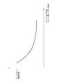
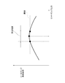
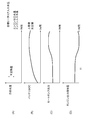
- FIG. 2 is a diagram showing the relationship between the engine outlet water temperature and the heat generation efficiency of the heat pump.
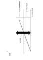
- FIG. 3 is a diagram conceptually illustrating an example of a map of the engine heating increase amount.
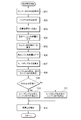
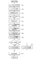
- FIG. 4 is a flowchart showing a flow of processing of the heating heat amount control routine of the first embodiment.
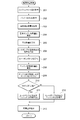
- FIG. 5 is a flowchart showing a flow of processing of the heating heat amount control routine of the second embodiment.
- FIG. 6 is a diagram for explaining a method for calculating an insufficient heat quantity.
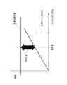
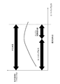
- FIG. 7 is a diagram illustrating a method for calculating the heat pump output.
- FIG. 1 is a diagram illustrating a schematic configuration of a hybrid vehicle control system according to a first embodiment.
- FIG. 2 is a diagram showing the relationship between the engine outlet water temperature and the heat generation efficiency of the heat pump.
- FIG. 3 is a diagram conceptually illustrating
- FIG. 8 is a diagram for explaining a method of calculating the engine heating increase amount.
- FIG. 9 is a flowchart showing the flow of processing of the heating heat amount control routine of the third embodiment.
- FIG. 10 is a diagram illustrating an example of characteristics of heat generation efficiency of the heat pump.
- FIG. 11 is a diagram illustrating an example of the characteristics of the power generation efficiency of the engine.
- FIG. 12 is a diagram illustrating a method for calculating the heat pump output and the engine heating increase amount.
- FIG. 13 is a diagram conceptually illustrating an example of an engine output increase map.
- FIG. 14 is a time chart illustrating an execution example of heating heat amount control according to the third embodiment.
- Example 1 will be described with reference to FIGS. First, a schematic configuration of a hybrid vehicle control system will be described with reference to FIG.
- An engine 11 that is an internal combustion engine and a motor generator (hereinafter referred to as “MG”) 12 are mounted as power sources for the vehicle.
- the power of the crankshaft that is the output shaft of the engine 11 is transmitted to the transmission 13 via the MG 12.
- the power of the output shaft of the transmission 13 is transmitted to the wheels 16 as drive wheels via the differential gear mechanism 14 and the axle 15.
- the transmission 13 may be a stepped transmission that switches a gear step among a plurality of gear steps, or may be a continuously variable transmission such as a CVT that changes continuously.
- Rotational shaft of the MG 12 is connected between the engine 11 and the transmission 13 in the power transmission path for transmitting the power of the engine 11 to the wheels 16 so that the power can be transmitted.
- a clutch for interrupting power transmission may be provided between the engine 11 and the MG 12 or between the MG 12 and the transmission 13.
- the generated power of the generator 17 driven by the power of the engine 11 is charged in the high voltage battery 18.
- An inverter 19 that drives the MG 12 is connected to the high voltage battery 18, and the MG 12 exchanges power with the high voltage battery 18 through the inverter 19.
- a low voltage battery 21 is connected to the generator 17 via a DC-DC converter 20.
- Both the high voltage battery 18 and the low voltage battery 21 are chargeable / dischargeable batteries, and a DC-DC converter 20 is connected between the high voltage battery 18 and the low voltage battery 21. Further, the DC-DC converter 20 is connected to a low-voltage load that consumes electric power supplied from the high-voltage battery 18 via the DC-DC converter 20 or electric power supplied from the low-voltage battery 21.
- a hot water heating device 22 that uses the heat of the cooling water of the engine 11 is mounted.
- a heating coolant circuit 23 is connected to a coolant passage that is a water jacket of the engine 11.
- the heating coolant circuit 23 is provided with an electric water pump 24 and a heater core 25 for heating.
- the heating coolant circuit 23 is provided with a heat pump 26 in addition to the engine 11 as a heat source for heating the coolant.
- a heat pump 26 is disposed on the downstream side of the engine 11, and a heater core 25 is disposed on the downstream side of the heat pump 26.
- the electric water pump 24 is driven by the electric power of the low voltage battery 21.
- the electric water pump 24 causes the cooling water to circulate through the heating cooling water circuit 23.
- the cooling water circulates and flows in the order of the engine 11, the heat pump 26, the heater core 25, and the engine 11.
- the heat pump 26 compresses the low-temperature and low-pressure gas refrigerant into the high-temperature and high-pressure gas refrigerant with the electric compressor 27, and then releases the heat from the high-temperature and high-pressure gas refrigerant into the high-pressure liquid refrigerant with the heater 28. Thereafter, the high-pressure liquid refrigerant is decompressed and expanded by the expansion valve 29 to form a low-temperature and low-pressure liquid refrigerant, and the outdoor heat exchanger 30 absorbs heat into the low-temperature and low-pressure liquid refrigerant to form a low-temperature and low-pressure gas refrigerant.
- the heater 28 of the heat pump 26 exchanges heat between the refrigerant and the cooling water to heat the cooling water with the heat of the refrigerant.
- the heater core 25 exchanges heat between the cooling water and the air to heat the air with the heat of the cooling water.
- a blower fan 32 that generates warm air is disposed in the vicinity of the heater core 25.
- the heating coolant circuit 23 includes an engine outlet water temperature sensor 31 that detects an engine outlet water temperature that is the temperature of the cooling water flowing out from the engine 11 as a water temperature sensor that detects the temperature of the cooling water flowing through the heating coolant circuit 23. Is arranged.
- the accelerator opening that is the operation amount of the accelerator pedal is detected by the accelerator sensor 34.
- An operating position of the shift lever is detected by the shift switch 35.
- the brake operation is detected by the brake switch 36.
- the brake operation amount may be detected by a brake sensor.
- the vehicle speed is detected by the vehicle speed sensor 37.
- the acceleration sensor 38 detects acceleration.
- the hybrid ECU 39 is a control device that comprehensively controls the entire vehicle, and detects the driving state of the vehicle by reading the output signals of the various sensors and switches described above.
- the hybrid ECU 39 transmits and receives control signals, data signals, and the like among the engine ECU 40, the MG-ECU 41, and the air conditioner ECU.
- the engine ECU 40 is a control device that controls the operation of the engine 11.
- the MG-ECU 41 is a control device that controls the generator 19 and the DC-DC converter 20 while controlling the MG 12 by controlling the inverter 19.
- the air conditioner ECU 42 is a control device that controls the hot water heating device 22.
- the air conditioner ECU 42 controls, for example, the electric water pump 24, the electric compressor 27, the blower fan 32, and the like.
- the hybrid ECU 39 controls the engine 11, the MG 12, the generator 17, the DC-DC converter 20, the hot water heater 22 and the like by the ECUs 40, 41 and 42 according to the driving state of the vehicle. Further, the hybrid ECU 39 transmits and receives control signals and data signals to and from the power supply ECU 43 that monitors the high voltage battery 18.
- the hybrid ECU 39 switches the travel mode between, for example, an engine travel mode, an assist travel mode, and an EV travel mode.
- engine running mode engine running is performed in which the vehicle 16 is driven by driving the wheels 16 only with the power of the engine 11.
- assist travel is performed in which the vehicle 16 travels by driving the wheels 16 with both the power of the engine 11 and the power of the MG 12.
- EV travel mode EV travel is performed in which the vehicle 16 travels by driving the wheels 16 only with the power of the MG 12. This EV traveling is permitted, for example, when the engine outlet water temperature is equal to or higher than the warm-up completion water temperature at which the engine can be stopped.
- the hybrid ECU 39 switches the traveling mode to the regenerative power generation mode when braking the vehicle.
- a braking force is generated when the accelerator is off or the brake is on.
- the MG 12 is driven by the power of the wheels 16 to perform regenerative power generation by converting the kinetic energy of the vehicle into electrical energy by the MG 12, and the regenerative power that is the generated power is charged in the high-voltage battery 18.
- the heat pump inlet water temperature is the temperature of the cooling water flowing into the heat pump 26.
- the heat generation efficiency of the heat pump 26 is, for example, the ratio of the cooling water heating amount to the energy consumption of the heat pump 26.
- the output of the heat pump 26 is decreased as the engine outlet water temperature is higher, the power consumption of the heat pump 26 can be suppressed and the fuel efficiency can be improved.
- the output of the heat pump 26 is simply reduced as the engine outlet water temperature is higher, the cooling water heating amount may be insufficient and the target heating heat amount may not be ensured.
- the hybrid ECU 39 sets the output of the heat pump 26 and the output of the engine 11 according to the engine outlet water temperature, and executes heating heat amount control for realizing the target heating heat amount.
- the output of the heat pump 26 and the output of the engine 11 can be changed in response to the heat generation efficiency of the heat pump 26 changing according to the engine outlet water temperature.
- the output of the heat pump 26 is reduced to improve fuel efficiency, while the output of the engine 11 is increased to increase the cooling water heating amount of the engine 11 to achieve target heating.
- the amount of heat can be secured.
- the hybrid ECU 39 increases the power generation amount of the generator 17 by an amount corresponding to the increase in the output of the engine 11 by the heating heat amount control.
- the driving force of the vehicle may be changed, not only the power generation amount but also the driving force of the vehicle may be increased by increasing the output of the engine 11 by heating heat amount control.
- the following heating heat amount control is performed by executing a heating heat amount control routine of FIG.
- control is performed to reduce the output of the heat pump 26 and increase the output of the engine 11 to achieve the target heating heat amount as the engine outlet water temperature increases.
- the heating heat amount control routine shown in FIG. 4 is repeatedly executed at a predetermined period during the power-on period of the hybrid ECU 39, and serves as an output control unit of the present disclosure.
- step 101 the engine outlet water temperature detected by the engine outlet water temperature sensor 31 is acquired. Thereafter, the process proceeds to step 102, and an SOC representing the remaining capacity of the high voltage battery 18 is acquired.
- the process proceeds to step 103, where the target heating heat amount that is the required heating load is set based on the target heating water temperature or the like.
- the target heating heat amount is, for example, a target value of the cooling water heat radiation amount that is the air heating amount per unit time of the heater core 25.
- the target heating water temperature is, for example, a target value of the heater core inlet water temperature, and is set based on the outside air temperature, the vehicle interior temperature, the target vehicle interior temperature, and the like.
- the heater core inlet water temperature is the temperature of the cooling water flowing into the heater core 25.
- the process proceeds to step 104, and the basic engine heating amount is calculated by a map or a mathematical formula according to the required travel load and the required power generation load.
- the basic engine heating amount is the cooling water heating amount per unit time of the engine 11 at the basic output of the engine 11 set according to the required travel load and the required power generation load.
- the required travel load is a required travel output set based on, for example, the accelerator opening.
- the required power generation load is a required power generation amount set based on, for example, the SOC of the high-voltage battery 18.
- the process proceeds to step 105, and the engine heating increase amount is calculated by a map or a mathematical formula according to the engine outlet water temperature.
- the engine heating increase amount is an increase amount of the cooling water heating amount per unit time of the engine 11. As shown in FIG. 3, the engine heating increase map or formula is set such that the engine heating increase increases as the engine outlet water temperature increases.
- step 106 the total engine heating amount is obtained by adding the engine heating increase amount to the basic engine heating amount.
- Total engine heating basic engine heating + engine heating increase
- step 107 the total engine heating amount is subtracted from the target heating heat amount to obtain the output of the heat pump 26 (that is, the cooling water heating amount per unit time of the heat pump 26).
- Heat pump output target heating amount-total engine heating amount
- step 108 the output increase amount of the engine 11 is calculated by a map or a mathematical expression or the like according to the engine heating increase amount.
- the output increase of the engine 11 is obtained by adding the output increase amount of the engine 11 to the basic output of the engine 11.
- the process proceeds to step 109, and it is determined whether or not the SOC of the high voltage battery 18 is equal to or less than a predetermined value.
- the predetermined value is set to a value slightly smaller than the upper limit value of the SOC of the high voltage battery 18, for example.
- step 109 If it is determined in step 109 that the SOC of the high-voltage battery 18 is equal to or less than the predetermined value, the process proceeds to step 110 to correct the output of the heat pump 26 set in step 107 and the output of the engine 11 set in step 108. Adopt as it is without. Thereafter, the process proceeds to step 112, where the power generation amount of the generator 17 is increased by an amount corresponding to the output increase amount of the engine 11 set in step 108, thereby adding to the required power generation amount.
- step 111 the output increase amount of the engine 11 set in the above step 108 is corrected to decrease, the output of the engine 11 is corrected to decrease, and the output of the heat pump 26 set in the above step 107 is corrected to increase.
- the output correction amount corresponding to the SOC of the high voltage battery 18 is calculated by a map or a mathematical expression.
- the output correction amount map or mathematical expression is set such that, for example, the output correction amount increases as the SOC of the high-voltage battery 18 increases.
- the output increase amount of the engine 11 set in step 108 is corrected to decrease, and the output of the engine 11 is corrected to decrease.
- the output of the heat pump 26 set in step 107 is increased by the amount corresponding to the decrease correction of the output of the engine 11.
- the decrease correction amount is, for example, an amount corresponding to a decrease amount of the cooling water heating amount due to the decrease correction.
- step 112 the power generation amount of the generator 17 is increased by an amount corresponding to the output increase amount of the engine 11 corrected for reduction in step 111, and added to the required power generation amount.
- the output of the heat pump 26 is decreased and the output of the engine 11 is increased as the engine outlet water temperature is increased, thereby realizing the target heating heat amount.
- the output of the engine 11 is increased and the target heating is increased while the output of the heat pump 26 is reduced to improve fuel efficiency.
- the amount of heat can be secured. Thereby, the target heating calorie
- the power generation amount of the generator 17 is increased by the increase in the output of the engine 11 by the heating heat amount control. Therefore, it is possible to prevent the driving force of the vehicle from increasing due to an increase in the output of the engine 11 due to heating heat amount control, and to prevent deterioration of drivability due to heating heat amount control.
- the driving force may be increased.
- the output of the heat pump 26 and the output of the engine 11 are corrected according to the SOC of the high-voltage battery 18 during execution of the heating heat amount control. Specifically, when the SOC of the high-voltage battery 18 is larger than a predetermined value, the output of the engine 11 is corrected to decrease, and the output of the heat pump 26 is corrected to increase. In this way, when the SOC of the high voltage battery 18 approaches the upper limit value, the power generation amount of the generator 17 is decreased by correcting the output of the engine 11 to decrease, and the SOC of the high voltage battery 18 reaches the upper limit value.
- heat amount can be ensured by carrying out the increase correction
- the amount of reduction correction of the output of the engine 11 is an amount corresponding to a reduction amount of the cooling water heating amount due to the reduction correction, for example.
- Example 2 will be described with reference to FIGS. However, description of substantially the same or similar parts as in the first embodiment will be omitted or simplified, and different parts from the first embodiment will be mainly described.
- the heat efficiency of the heat pump 26 changes depending on the output such as the rotational speed of the electric compressor 27, for example, and the output range in which the heat generation efficiency increases according to the engine outlet water temperature.
- the following heating heat amount control is performed by executing a heating heat amount control routine of FIG.
- the output of the heat pump 26 is set to a value within a predetermined range set according to the engine outlet water temperature, and the engine is set so as to realize the target heating heat amount at the set output of the heat pump 26. 11 is controlled.
- the routine of FIG. 5 also serves as an output control unit of the present disclosure.
- step 201 the engine outlet water temperature detected by the engine outlet water temperature sensor 31 is acquired. Thereafter, the process proceeds to step 202, and the SOC of the high voltage battery 18 is acquired. Then, it progresses to step 203 and sets target heating calorie
- step 206 the current heat generation efficiency characteristics of the heat pump 26 are calculated based on the engine outlet water temperature, the outside air temperature, the vehicle speed, the refrigerant pressure, and the like.
- the heat generation efficiency of the heat pump 26 is the ratio of the cooling water heating amount to the energy consumption of the heat pump 26. In this case, as shown in FIG. 7, the relationship between the output of the heat pump 26 and the heat generation efficiency is obtained as a characteristic of the heat generation efficiency of the heat pump 26.
- the characteristics of the heat generation efficiency of the heat pump 26 according to the engine outlet water temperature, the outside air temperature, the vehicle speed, the refrigerant pressure, etc. may be stored in advance in the ROM of the hybrid ECU 39 or the like.
- the process proceeds to step 207, and the output of the heat pump 26 is set to a value within a predetermined range using the heat generation efficiency characteristic of the heat pump 26, as shown in FIG.
- the predetermined range is an output range of the heat pump 26 in which the heat generation efficiency of the heat pump 26 is equal to or greater than a threshold, and the threshold is set to, for example, the maximum value of heat generation efficiency ⁇ 0.9.
- the output of the heat pump 26 is set to an output value at which the heat generation efficiency of the heat pump 26 is the highest.
- the output value at which the heat generation efficiency of the heat pump 26 is the highest is the output value at which the heat generation efficiency is the maximum value.
- step 208 the output of the heat pump 26 (that is, the cooling water heating amount) is subtracted from the insufficient heat amount to obtain the engine heating increase amount.
- Engine heating increase insufficient heat-heat pump output
- step 209 the output increase amount of the engine 11 is calculated by a map or a mathematical formula according to the engine heating increase amount.
- the output increase of the engine 11 is obtained by adding the output increase amount of the engine 11 to the basic output of the engine 11.
- step 210 it is determined whether or not the SOC of the high voltage battery 18 is equal to or less than a predetermined value. If it is determined in step 210 that the SOC of the high-voltage battery 18 is equal to or lower than the predetermined value, the process proceeds to step 211 to correct the output of the heat pump 26 set in step 207 and the output of the engine 11 set in step 209. Adopt as it is without. Thereafter, the process proceeds to step 213, and the power generation amount of the generator 17 is increased by an amount corresponding to the output increase amount of the engine 11 set in step 209.
- step 210 if it is determined in step 210 that the SOC of the high voltage battery 18 is greater than the predetermined value, the process proceeds to step 212.
- step 212 the output increase amount of the engine 11 set in step 209 is corrected to decrease to correct the output of the engine 11, and the output of the heat pump 26 set in step 207 is corrected to increase. Thereafter, the process proceeds to step 213, and the power generation amount of the generator 17 is increased by an amount corresponding to the output increase amount of the engine 11 corrected for the decrease in step 212.
- the output of the heat pump 26 is an output within a range where the heat generation efficiency is equal to or more than a threshold in the heat generation efficiency characteristic of the heat pump 26 set according to the engine outlet water temperature.
- the output of the heat pump 26 is set to an output value at which the heat generation efficiency of the heat pump 26 is highest.
- the output of the engine 11 is set so as to realize the target heating heat amount at the set output of the heat pump 26. Even in this case, the target heating heat quantity can be secured while improving the fuel consumption by coordinating the heat pump 26 and the engine 11.
- the output of the heat pump 26 can be set to an output value at which the heat generation efficiency of the heat pump 26 is highest at the engine outlet water temperature at that time, fuel efficiency can be improved effectively.
- the output of the heat pump 26 is set to an output value at which the heat generation efficiency of the heat pump 26 is the highest.
- the output of the heat pump 26 may be set to a value other than the output value at which the heat generation efficiency of the heat pump 26 is highest.
- the rotational speed of the electric compressor 27 may be used as substitute information for the output of the heat pump 26. That is, the rotational speed of the electric compressor 27 may be set to a rotational speed value within a range in which the heat generation efficiency is equal to or greater than the threshold in the heat generation efficiency characteristic of the heat pump 26 set according to the engine outlet water temperature.
- the following heating heat amount control is performed by executing a heating heat amount control routine of FIG.
- the heat generation efficiency characteristic of the heat pump 26 is set based on the engine outlet water temperature and the like.
- the heat generation efficiency of the heat pump 26 is the ratio of the cooling water heating amount to the energy consumption of the heat pump 26.
- the characteristic of the power generation efficiency of the engine 11 is set.
- the power generation efficiency of the engine 11 is a ratio of the power generation amount of the generator 17 to the fuel consumption amount of the engine 11.
- the control which sets the output of the heat pump 26 and the output of the engine 11 is performed so that the total efficiency combining the heat generation efficiency of the heat pump 26 and the power generation efficiency of the engine 11 under the condition that the target heating heat quantity can be realized.
- the routine of FIG. 9 also serves as an output control unit of the present disclosure.
- step 301 the engine outlet water temperature detected by the engine outlet water temperature sensor 31 is acquired. Thereafter, the process proceeds to step 302 to acquire the SOC of the high voltage battery 18. Thereafter, the process proceeds to step 303, where the target heating heat quantity is set based on the target heating water temperature or the like. Thereafter, the process proceeds to step 304, and the basic engine heating amount is calculated by a map or a mathematical formula according to the required travel load and the required power generation load.
- step 305 the basic engine heating amount is subtracted from the target heating heat amount to obtain the insufficient heat amount.
- Insufficient heat Target heating value-Basic engine heating value
- step 306 the current heat generation efficiency characteristics of the heat pump 26 are calculated based on the engine outlet water temperature, the outside air temperature, the vehicle speed, the refrigerant pressure, and the like.
- the relationship between the output of the heat pump 26 and the heat generation efficiency is obtained as the heat generation efficiency characteristic of the heat pump 26.
- the characteristics of the heat generation efficiency of the heat pump 26 according to the engine outlet water temperature, the outside air temperature, the vehicle speed, the refrigerant pressure, etc. may be stored in advance in the ROM of the hybrid ECU 39 or the like.
- step 307 the current power generation efficiency characteristic of the engine 11 is calculated based on the engine outlet water temperature, the outside air temperature, and the like.
- a characteristic of the power generation efficiency of the engine 11 a relationship between the engine heating increase amount due to the increase in the output of the engine 11 and the power generation efficiency is obtained.
- step 308 the output of the heat pump 26 and the engine heating increase amount are set so that the total efficiency combining the heat generation efficiency of the heat pump 26 and the power generation efficiency of the engine 11 becomes the highest under the condition that the target heating heat amount can be secured. calculate.
- the total efficiency K is an efficiency obtained by multiplying the heat generation efficiency Kh of the heat pump 26 and the power generation efficiency Ke of the engine 11.
- Total efficiency K heat pump heat generation efficiency Kh x engine power generation efficiency Ke
- the process proceeds to step 309, and the output increase amount of the engine 11 is calculated by a map or a mathematical expression according to the engine heating increase amount.
- the map or formula of the output increase amount of the engine 11 is set so that the output increase amount of the engine 11 increases as the engine heating increase amount increases.
- the output increase of the engine 11 is obtained by adding the output increase amount of the engine 11 to the basic output of the engine 11. In this way, the output of the heat pump 26 and the output of the engine 11 at which the overall efficiency K becomes the highest under the condition that the target heating heat quantity can be secured are obtained.
- step 310 it is determined whether or not the SOC of the high voltage battery 18 is equal to or less than a predetermined value. If it is determined in step 310 that the SOC of the high voltage battery 18 is equal to or lower than the predetermined value, the process proceeds to step 311 to correct the output of the heat pump 26 set in step 308 and the output of the engine 11 set in step 309. Adopt as it is. Thereafter, the process proceeds to step 313, and the power generation amount of the generator 17 is increased by an amount corresponding to the output increase amount of the engine 11 set in step 309.
- step 310 determines whether the SOC of the high voltage battery 18 is greater than the predetermined value. If it is determined in step 310 that the SOC of the high voltage battery 18 is greater than the predetermined value, the process proceeds to step 312. In step 312, the output increase of the engine 11 set in step 309 is corrected to decrease to correct the output of the engine 11, and the output of the heat pump 26 set in step 308 is corrected to increase. Thereafter, the process proceeds to step 313, and the power generation amount of the generator 17 is increased by an amount corresponding to the output increase amount of the engine 11 corrected by the decrease in step 312.
- the heat generation efficiency characteristics of the heat pump 26 and the power generation efficiency characteristics of the engine 11 are set based on the engine outlet water temperature and the like during heating heat amount control. Then, based on the heat generation efficiency characteristics of the heat pump 26 and the power generation efficiency characteristics of the engine 11, the output of the heat pump 26 and the output of the engine 11 are set so that the overall efficiency K becomes the highest under the condition that the target heating amount can be realized. I am trying to set it. Even in this case, the target heating heat quantity can be secured while improving the fuel consumption by coordinating the heat pump 26 and the engine 11. Moreover, since the overall efficiency combining the heat generation efficiency of the heat pump 26 and the power generation efficiency of the engine 11 can be maximized, the fuel efficiency can be improved more effectively.
- FIG. 14 is used to explain an execution example of the heating heat amount control of the third embodiment.
- FIG. 14A shows the cooling water temperature.
- FIG. 14B shows the battery SOC.
- FIG. 14C shows the heat pump output.
- FIG. 14D shows the engine output increase amount.
- FIG. 14 shows a case where the required heating load is constant and the required traveling load + the required power generation load is constant.
- the engine outlet water temperature in FIG. 14 indicates the water temperature when the output of the engine 11 is not increased by the heating heat quantity control.
- the case where the output of the engine 11 is not increased by the heating heat amount control is a case where the engine heating increase amount is not included.
- the output of the heat pump 26 and the output of the engine 11 at which the overall efficiency K becomes the highest under the condition that the target heating heat amount can be secured are obtained.
- the output of the heat pump 26 and the output of the engine 11 at which the overall efficiency K is the highest are employed as they are. Thereby, target heating calorie
- the power generation amount of the generator 17 is increased by the increase in the output of the engine 11 by the heating heat amount control.
- the present invention is not limited to this, and the output torque of the MG 12 may be decreased by an amount corresponding to the increase in the output of the engine 11 by the heating heat amount control.
- the power generation amount of the MG 12 may be increased by an amount corresponding to the increase in the output of the engine 11 by the heating heat amount control.
- the hybrid ECU 39 executes the heating heat amount control routine.
- the heating heat amount control routine may be executed by an ECU other than the hybrid ECU 39.
- the heating heat amount control routine may be executed by at least one of the engine ECU 40, the MG-ECU 41, the air conditioner ECU 42, and the like.
- the heating heat amount control routine may be executed by both the hybrid ECU 39 and another ECU.
- some or all of the functions executed by the ECU may be configured by hardware using one or a plurality of ICs.
- the present disclosure is not limited to the vehicle having the configuration shown in FIG. 1, and can be applied to vehicles having various configurations including a heat pump that heats engine coolant that is a power source of the vehicle.
Abstract
A heat pump 26 and a heater core 25 are provided to a cooling water circuit 23 for heating, the cooling water circuit 23 being connected to an engine 11. As a heating heat level control, a control is performed in which the output of the heat pump 26 is reduced as the engine outlet water temperature detected by an engine outlet water temperature sensor 31 increases, and the output of the engine 11 is decreased to achieve a target heating heat level. This increases the output of the engine 11 and ensures the target heating heat level while reducing the output of the heat pump 26 and improving fuel efficiency, in response to the heating efficiency of the heat pump 26 falling as the engine outlet water temperature increases.
Description
本出願は、2016年2月2日に出願された日本国特許出願2016-18401号に基づくものであって、その優先権の利益を主張するものであり、その特許出願の全ての内容が、参照により本明細書に組み込まれる。
This application is based on Japanese Patent Application No. 2016-18401 filed on February 2, 2016 and claims the benefit of its priority. Which is incorporated herein by reference.
本開示は、車両の空調装置に関する。
The present disclosure relates to a vehicle air conditioner.
近年、低燃費、低排気エミッションの社会的要請から車両の動力源としてエンジンとモータとを搭載したハイブリッド車が注目されている。このようなハイブリッド車においては、エンジンを停止してモータの動力で走行するEV走行を行うことで燃費を向上させるようにしたものがある。しかし、冬季等に暖房用の熱量を確保するためにエンジンを稼働する時間が長くなると、燃費が悪化する傾向がある。暖房用の熱量とは、エンジンの冷却水の熱量である。
In recent years, hybrid vehicles equipped with an engine and a motor are attracting attention as a power source for vehicles due to social demands for low fuel consumption and low exhaust emissions. In such a hybrid vehicle, there is one in which fuel efficiency is improved by performing EV traveling in which the engine is stopped and the vehicle is driven by the power of the motor. However, if the engine is operated for a long time in order to ensure the amount of heat for heating in winter, the fuel consumption tends to deteriorate. The amount of heat for heating is the amount of heat of engine cooling water.
そこで、特許文献1に記載されているように、エンジン以外に冷却水を加熱する加熱装置を搭載するようにしたものがある。このものは、冷却水を加熱する加熱装置としてヒートポンプや排気熱回収器を設け、冷却水の温度、排出ガスの温度、エンジン出力に基づいて、ヒートポンプのコンプレッサの回転速度を制御することで、ヒートポンプの消費電力を抑制するようにしている。
Therefore, as described in Patent Document 1, there is a device equipped with a heating device for heating cooling water in addition to the engine. This is a heat pump or exhaust heat recovery device as a heating device that heats the cooling water, and controls the rotation speed of the compressor of the heat pump based on the temperature of the cooling water, the temperature of the exhaust gas, and the engine output. The power consumption is suppressed.
冷却水温が高いほどヒートポンプの発熱効率が低下するため、冷却水温が高いほどヒートポンプの出力を小さくすれば、ヒートポンプの消費電力を抑制して燃費を向上させることができる。ヒートポンプの発熱効率の一例としては、消費エネルギに対する冷却水加熱量の割合である。
Since the heat pump efficiency decreases as the cooling water temperature increases, the power consumption of the heat pump can be reduced and the fuel consumption can be improved by reducing the heat pump output as the cooling water temperature increases. One example of the heat generation efficiency of the heat pump is the ratio of the cooling water heating amount to the energy consumption.
しかし、単に冷却水温が高いほどヒートポンプの出力を小さくするだけでは、冷却水加熱量が不足して目標暖房熱量を確保できなくなる可能性がある。また、上記特許文献1に記載されている技術では、冷却水温やエンジン出力に応じてヒートポンプの出力を設定し、冷却水温やエンジン出力が高いほどヒートポンプのコンプレッサの回転速度を低くしてヒートポンプの出力を小さくするようにしている。このため、エンジン出力によっては、冷却水温が高くてもヒートポンプの出力をあまり小さくすることができず、燃費を効果的に向上させることができない可能性がある。
However, simply reducing the output of the heat pump as the cooling water temperature is higher may cause the cooling water heating amount to be insufficient and the target heating heat amount not to be secured. In the technique described in Patent Document 1, the output of the heat pump is set in accordance with the cooling water temperature and the engine output, and the higher the cooling water temperature and the engine output, the lower the rotation speed of the compressor of the heat pump and the output of the heat pump. I try to make it smaller. For this reason, depending on the engine output, even if the coolant temperature is high, the output of the heat pump cannot be made too small, and the fuel efficiency may not be improved effectively.
本開示は、エンジンの冷却水を加熱するヒートポンプを備えたシステムにおいて目標暖房熱量を確保しながら燃費を向上させることができる車両の空調装置を提供することを目的とする。
This disclosure is intended to provide a vehicle air conditioner that can improve fuel efficiency while ensuring a target heating amount in a system including a heat pump that heats engine coolant.
本開示は、車両の空調装置であって、車両の動力源であるエンジン(11)とエンジンの冷却水を加熱するヒートポンプ(26)との間で冷却水が循環する暖房用冷却水回路(23)と、暖房用冷却水回路を流れる冷却水の温度を検出する水温センサ(31)と、水温センサで検出した冷却水の温度である冷却水温に応じてヒートポンプの出力とエンジンの出力を設定して所定の目標暖房熱量を実現する暖房熱量制御を実行する出力制御部(39)と、を備える。
The present disclosure is an air conditioner for a vehicle, and includes a cooling water circuit for heating (23) in which cooling water circulates between an engine (11) that is a power source of the vehicle and a heat pump (26) that heats the cooling water of the engine. ), A water temperature sensor (31) for detecting the temperature of the cooling water flowing through the cooling water circuit for heating, and the output of the heat pump and the output of the engine according to the cooling water temperature detected by the water temperature sensor. And an output control unit (39) for performing heating heat amount control for realizing a predetermined target heating heat amount.
本開示によれば、冷却水温に応じてヒートポンプの出力とエンジンの出力を設定して目標暖房熱量を実現する暖房熱量制御を実行することができる。この暖房熱量制御では、冷却水温に応じてヒートポンプの発熱効率が変化するのに対応して、ヒートポンプの出力とエンジンの出力を変化させることができる。これにより、ヒートポンプの発熱効率が低い水温領域で、ヒートポンプの出力を減少させて燃費を向上させながら、エンジンの出力を増加させることでエンジンの冷却水加熱量を増加させて目標暖房熱量を確保することができる。
According to the present disclosure, it is possible to execute the heating heat amount control for realizing the target heating heat amount by setting the output of the heat pump and the output of the engine according to the cooling water temperature. In this heating heat quantity control, the output of the heat pump and the output of the engine can be changed in response to the heat generation efficiency of the heat pump changing according to the cooling water temperature. As a result, in the water temperature region where heat generation efficiency of the heat pump is low, while reducing the output of the heat pump and improving fuel efficiency, increasing the engine output by increasing the engine output ensures the target heating heat amount be able to.
尚、「発明の概要」及び「特許請求の範囲」に記載した括弧内の符号は、後述する「発明を実施するための形態」との対応関係を示すものであって、「発明の概要」及び「特許請求の範囲」が、後述する「発明を実施するための形態」に限定されることを示すものではない。
The reference numerals in parentheses described in the “Summary of the Invention” and the “Claims” indicate the correspondence with the “Mode for Carrying Out the Invention” described later, and the “Summary of the Invention” Further, this does not mean that the “claims” are limited to the “mode for carrying out the invention” described later.
以下、添付図面を参照しながら本実施形態について説明する。説明の理解を容易にするため、各図面において同一の構成要素に対しては可能な限り同一の符号を付して、重複する説明は省略する。
Hereinafter, the present embodiment will be described with reference to the accompanying drawings. In order to facilitate the understanding of the description, the same constituent elements in the drawings will be denoted by the same reference numerals as much as possible, and redundant description will be omitted.
実施例1について図1乃至図4を参照しながら説明する。まず、図1に基づいてハイブリッド車の制御システムの概略構成を説明する。
Example 1 will be described with reference to FIGS. First, a schematic configuration of a hybrid vehicle control system will be described with reference to FIG.
車両の動力源として内燃機関であるエンジン11とモータジェネレータ(以下「MG」と表記する)12とが搭載されている。エンジン11の出力軸であるクランク軸の動力がMG12を介して変速機13に伝達される。この変速機13の出力軸の動力がデファレンシャルギヤ機構14や車軸15等を介して駆動輪としての車輪16に伝達される。変速機13は、複数段の変速段の中から変速段を段階的に切り換える有段変速機であっても良いし、無段階に変速するCVTといった無段変速機であっても良い。
An engine 11 that is an internal combustion engine and a motor generator (hereinafter referred to as “MG”) 12 are mounted as power sources for the vehicle. The power of the crankshaft that is the output shaft of the engine 11 is transmitted to the transmission 13 via the MG 12. The power of the output shaft of the transmission 13 is transmitted to the wheels 16 as drive wheels via the differential gear mechanism 14 and the axle 15. The transmission 13 may be a stepped transmission that switches a gear step among a plurality of gear steps, or may be a continuously variable transmission such as a CVT that changes continuously.
エンジン11の動力を車輪16に伝達する動力伝達経路のうちのエンジン11と変速機13との間に、MG12の回転軸が動力伝達可能に連結されている。尚、エンジン11とMG12との間、又はMG12と変速機13との間に、動力伝達を断続するためのクラッチを設けるようにしても良い。
Rotational shaft of the MG 12 is connected between the engine 11 and the transmission 13 in the power transmission path for transmitting the power of the engine 11 to the wheels 16 so that the power can be transmitted. A clutch for interrupting power transmission may be provided between the engine 11 and the MG 12 or between the MG 12 and the transmission 13.
エンジン11の動力で駆動される発電機17の発電電力が高圧バッテリ18に充電され る。また、MG12を駆動するインバータ19が高圧バッテリ18に接続され、MG12がインバータ19を介して高圧バッテリ18と電力を授受する。発電機17には、DC-DCコンバータ20を介して低圧バッテリ21が接続されている。
The generated power of the generator 17 driven by the power of the engine 11 is charged in the high voltage battery 18. An inverter 19 that drives the MG 12 is connected to the high voltage battery 18, and the MG 12 exchanges power with the high voltage battery 18 through the inverter 19. A low voltage battery 21 is connected to the generator 17 via a DC-DC converter 20.
高圧バッテリ18と低圧バッテリ21は、いずれも充放電可能なバッテリであり、高圧バッテリ18と低圧バッテリ21との間に、DC-DCコンバータ20が接続されている。更に、DC-DCコンバータ20には、高圧バッテリ18からDC-DCコンバータ20を介して供給される電力又は低圧バッテリ21から供給される電力を消費する低圧負荷が接続されている。
Both the high voltage battery 18 and the low voltage battery 21 are chargeable / dischargeable batteries, and a DC-DC converter 20 is connected between the high voltage battery 18 and the low voltage battery 21. Further, the DC-DC converter 20 is connected to a low-voltage load that consumes electric power supplied from the high-voltage battery 18 via the DC-DC converter 20 or electric power supplied from the low-voltage battery 21.
また、車室内を暖房するための空調装置である暖房装置として、エンジン11の冷却水の熱を利用する温水暖房装置22が搭載されている。この温水暖房装置22は、エンジン11のウォータジャケットである冷却水通路に、暖房用冷却水回路23が接続されている。この暖房用冷却水回路23には、電動ウォータポンプ24と暖房用のヒータコア25が設けられている。更に、暖房用冷却水回路23には、冷却水を加熱する熱源として、エンジン11以外にヒートポンプ26が設けられている。エンジン11の下流側にヒートポンプ26が配置され、このヒートポンプ26の下流側にヒータコア25が配置されている。
Further, as a heating device that is an air conditioner for heating the passenger compartment, a hot water heating device 22 that uses the heat of the cooling water of the engine 11 is mounted. In the hot water heater 22, a heating coolant circuit 23 is connected to a coolant passage that is a water jacket of the engine 11. The heating coolant circuit 23 is provided with an electric water pump 24 and a heater core 25 for heating. Further, the heating coolant circuit 23 is provided with a heat pump 26 in addition to the engine 11 as a heat source for heating the coolant. A heat pump 26 is disposed on the downstream side of the engine 11, and a heater core 25 is disposed on the downstream side of the heat pump 26.
電動ウォータポンプ24は、低圧バッテリ21の電力で駆動される。この電動ウォータポンプ24により冷却水が暖房用冷却水回路23を循環して流れる。この際、本実施例1では、冷却水が、エンジン11、ヒートポンプ26、ヒータコア25、エンジン11の順で循環して流れる。
The electric water pump 24 is driven by the electric power of the low voltage battery 21. The electric water pump 24 causes the cooling water to circulate through the heating cooling water circuit 23. At this time, in the first embodiment, the cooling water circulates and flows in the order of the engine 11, the heat pump 26, the heater core 25, and the engine 11.
ヒートポンプ26は、電動コンプレッサ27で低温低圧のガス冷媒を圧縮して高温高圧のガス冷媒にした後、加熱器28で高温高圧のガス冷媒から熱を放出させて高圧の液状冷媒にする。この後、膨張弁29で高圧の液状冷媒を減圧膨張させて低温低圧の液状冷媒にした後、室外熱交換器30で低温低圧の液状冷媒に熱を吸収させて低温低圧のガス冷媒にする。
The heat pump 26 compresses the low-temperature and low-pressure gas refrigerant into the high-temperature and high-pressure gas refrigerant with the electric compressor 27, and then releases the heat from the high-temperature and high-pressure gas refrigerant into the high-pressure liquid refrigerant with the heater 28. Thereafter, the high-pressure liquid refrigerant is decompressed and expanded by the expansion valve 29 to form a low-temperature and low-pressure liquid refrigerant, and the outdoor heat exchanger 30 absorbs heat into the low-temperature and low-pressure liquid refrigerant to form a low-temperature and low-pressure gas refrigerant.
ヒートポンプ26の加熱器28は、冷媒と冷却水との間で熱交換して冷媒の熱で冷却水を加熱する。一方、ヒータコア25は、冷却水と空気との間で熱交換して冷却水の熱で空気を加熱する。ヒータコア25の近傍には、温風を発生させるブロアファン32が配置されている。
The heater 28 of the heat pump 26 exchanges heat between the refrigerant and the cooling water to heat the cooling water with the heat of the refrigerant. On the other hand, the heater core 25 exchanges heat between the cooling water and the air to heat the air with the heat of the cooling water. A blower fan 32 that generates warm air is disposed in the vicinity of the heater core 25.
暖房用冷却水回路23には、暖房用冷却水回路23を流れる冷却水の温度を検出する水温センサとして、エンジン11から流出する冷却水の温度であるエンジン出口水温を検出するエンジン出口水温センサ31が配置されている。
The heating coolant circuit 23 includes an engine outlet water temperature sensor 31 that detects an engine outlet water temperature that is the temperature of the cooling water flowing out from the engine 11 as a water temperature sensor that detects the temperature of the cooling water flowing through the heating coolant circuit 23. Is arranged.
また、アクセルセンサ34によってアクセルペダルの操作量であるアクセル開度が検出される。シフトスイッチ35によってシフトレバーの操作位置が検出される。ブレーキスイッチ36によってブレーキ操作が検出される。ブレーキセンサによってブレーキ操作量が検出されるようにしてもよい。車速センサ37によって車速が検出される。加速度センサ38によって加速度が検出される。
Further, the accelerator opening that is the operation amount of the accelerator pedal is detected by the accelerator sensor 34. An operating position of the shift lever is detected by the shift switch 35. The brake operation is detected by the brake switch 36. The brake operation amount may be detected by a brake sensor. The vehicle speed is detected by the vehicle speed sensor 37. The acceleration sensor 38 detects acceleration.
ハイブリッドECU39は、車両全体を総合的に制御する制御装置であり、上述した各種のセンサやスイッチの出力信号を読み込んで、車両の運転状態を検出する。このハイブリッドECU39は、エンジンECU40とMG-ECU41とエアコンECU42との間で制御信号やデータ信号等を送受信する。
The hybrid ECU 39 is a control device that comprehensively controls the entire vehicle, and detects the driving state of the vehicle by reading the output signals of the various sensors and switches described above. The hybrid ECU 39 transmits and receives control signals, data signals, and the like among the engine ECU 40, the MG-ECU 41, and the air conditioner ECU.
エンジンECU40は、エンジン11の運転を制御する制御装置である。MG-ECU 41は、インバータ19を制御してMG12を制御すると共に発電機17やDC-DCコンバータ20を制御する制御装置である。エアコンECU42は、温水暖房装置22を制御する制御装置である。エアコンECU42は、例えば電動ウォータポンプ24、電動コンプレッサ27、ブロアファン32等を制御する。
The engine ECU 40 is a control device that controls the operation of the engine 11. The MG-ECU 41 is a control device that controls the generator 19 and the DC-DC converter 20 while controlling the MG 12 by controlling the inverter 19. The air conditioner ECU 42 is a control device that controls the hot water heating device 22. The air conditioner ECU 42 controls, for example, the electric water pump 24, the electric compressor 27, the blower fan 32, and the like.
ハイブリッドECU39は、各ECU40,41,42によって車両の運転状態に応じて、エンジン11、MG12、発電機17、DC-DCコンバータ20、温水暖房装置22等を制御する。更に、ハイブリッドECU39は、高圧バッテリ18を監視する電源ECU43との間でも制御信号やデータ信号等を送受信する。
The hybrid ECU 39 controls the engine 11, the MG 12, the generator 17, the DC-DC converter 20, the hot water heater 22 and the like by the ECUs 40, 41 and 42 according to the driving state of the vehicle. Further, the hybrid ECU 39 transmits and receives control signals and data signals to and from the power supply ECU 43 that monitors the high voltage battery 18.
その際、ハイブリッドECU39は、走行モードを、例えば、エンジン走行モードとアシスト走行モードとEV走行モードとの間で切り換える。エンジン走行モードでは、エンジン11の動力のみで車輪16を駆動して車両を走行させるエンジン走行を行う。アシスト走行モードでは、エンジン11の動力とMG12の動力の両方で車輪16を駆動して車両を走行させるアシスト走行を行う。EV走行モードでは、MG12の動力のみで車輪16を駆動して車両を走行させるEV走行を行う。このEV走行は、例えば、エンジン出口水温がエンジン停止可能な暖機完了水温以上になったときに許可される。
At that time, the hybrid ECU 39 switches the travel mode between, for example, an engine travel mode, an assist travel mode, and an EV travel mode. In the engine running mode, engine running is performed in which the vehicle 16 is driven by driving the wheels 16 only with the power of the engine 11. In the assist travel mode, assist travel is performed in which the vehicle 16 travels by driving the wheels 16 with both the power of the engine 11 and the power of the MG 12. In the EV travel mode, EV travel is performed in which the vehicle 16 travels by driving the wheels 16 only with the power of the MG 12. This EV traveling is permitted, for example, when the engine outlet water temperature is equal to or higher than the warm-up completion water temperature at which the engine can be stopped.
また、ハイブリッドECU39は、車両を制動する際に、走行モードを回生発電モードに切り換える。車両を制動する際とは、例えばアクセルオフ時やブレーキオン時に制動力を発生させる際である。この回生発電モードでは、車輪16の動力でMG12を駆動することで、車両の運動エネルギをMG12で電気エネルギに変換する回生発電を行い、その発電電力である回生電力を高圧バッテリ18に充電する。これにより、アシスト走行やEV走行の実施可能時間を長くして燃費を向上させることができる。
The hybrid ECU 39 switches the traveling mode to the regenerative power generation mode when braking the vehicle. When the vehicle is braked, for example, a braking force is generated when the accelerator is off or the brake is on. In this regenerative power generation mode, the MG 12 is driven by the power of the wheels 16 to perform regenerative power generation by converting the kinetic energy of the vehicle into electrical energy by the MG 12, and the regenerative power that is the generated power is charged in the high-voltage battery 18. Thereby, the feasible time of assist driving | running | working and EV driving | running can be lengthened, and a fuel consumption can be improved.
ところで、図2に示すように、エンジン出口水温が高いほどヒートポンプ入口水温が高くなってヒートポンプ26の発熱効率が低下する。ヒートポンプ入口水温とは、ヒートポンプ26に流入する冷却水の温度である。ヒートポンプ26の発熱効率とは、例えばヒートポンプ26の消費エネルギに対する冷却水加熱量の割合である。
Incidentally, as shown in FIG. 2, the higher the engine outlet water temperature, the higher the heat pump inlet water temperature, and the heat generation efficiency of the heat pump 26 decreases. The heat pump inlet water temperature is the temperature of the cooling water flowing into the heat pump 26. The heat generation efficiency of the heat pump 26 is, for example, the ratio of the cooling water heating amount to the energy consumption of the heat pump 26.
このため、エンジン出口水温が高いほどヒートポンプ26の出力を小さくすれば、ヒートポンプ26の消費電力を抑制して燃費を向上させることができる。しかし、単にエンジン出口水温が高いほどヒートポンプ26の出力を小さくするだけでは、冷却水加熱量が不足して目標暖房熱量を確保できなくなる可能性がある。
For this reason, if the output of the heat pump 26 is decreased as the engine outlet water temperature is higher, the power consumption of the heat pump 26 can be suppressed and the fuel efficiency can be improved. However, if the output of the heat pump 26 is simply reduced as the engine outlet water temperature is higher, the cooling water heating amount may be insufficient and the target heating heat amount may not be ensured.
そこで、ハイブリッドECU39は、エンジン出口水温に応じてヒートポンプ26の出力とエンジン11の出力を設定して目標暖房熱量を実現する暖房熱量制御を実行する。この暖房熱量制御では、エンジン出口水温に応じてヒートポンプ26の発熱効率が変化するのに対応して、ヒートポンプ26の出力とエンジン11の出力を変化させることができる。これにより、ヒートポンプ26の発熱効率が低い水温領域で、ヒートポンプ26の出力を減少させて燃費を向上させながら、エンジン11の出力を増加させることでエンジン11の冷却水加熱量を増加させて目標暖房熱量を確保することができる。更に、ハイブリッドECU39は、暖房熱量制御によるエンジン11の出力増加分だけ発電機17の発電量を増加させる。ただし、車両の駆動力を変動させても良いと判断した場合には、暖房熱量制御によるエンジン11の出力増加によって発電量だけでなく車両の駆動力も増加させても良い。
Therefore, the hybrid ECU 39 sets the output of the heat pump 26 and the output of the engine 11 according to the engine outlet water temperature, and executes heating heat amount control for realizing the target heating heat amount. In this heating heat quantity control, the output of the heat pump 26 and the output of the engine 11 can be changed in response to the heat generation efficiency of the heat pump 26 changing according to the engine outlet water temperature. As a result, in the water temperature region where the heat generation efficiency of the heat pump 26 is low, the output of the heat pump 26 is reduced to improve fuel efficiency, while the output of the engine 11 is increased to increase the cooling water heating amount of the engine 11 to achieve target heating. The amount of heat can be secured. Further, the hybrid ECU 39 increases the power generation amount of the generator 17 by an amount corresponding to the increase in the output of the engine 11 by the heating heat amount control. However, when it is determined that the driving force of the vehicle may be changed, not only the power generation amount but also the driving force of the vehicle may be increased by increasing the output of the engine 11 by heating heat amount control.
本実施例1では、ハイブリッドECU39により後述する図4の暖房熱量制御ルーチンを実行することで次のような暖房熱量制御を行う。本実施例1の暖房熱量制御では、エンジン出口水温が高くなるほどヒートポンプ26の出力を減少させると共にエンジン11の出力を増加させて目標暖房熱量を実現する制御を行う。
In the first embodiment, the following heating heat amount control is performed by executing a heating heat amount control routine of FIG. In the heating heat amount control according to the first embodiment, control is performed to reduce the output of the heat pump 26 and increase the output of the engine 11 to achieve the target heating heat amount as the engine outlet water temperature increases.
以下、本実施例1でハイブリッドECU39が実行する図4の暖房熱量制御ルーチンの処理内容を説明する。図4に示す暖房熱量制御ルーチンは、ハイブリッドECU39の電源オン期間中に所定周期で繰り返し実行され、本開示の出力制御部としての役割を果たす。
Hereinafter, the processing content of the heating heat amount control routine of FIG. 4 executed by the hybrid ECU 39 in the first embodiment will be described. The heating heat amount control routine shown in FIG. 4 is repeatedly executed at a predetermined period during the power-on period of the hybrid ECU 39, and serves as an output control unit of the present disclosure.
本ルーチンが起動されると、まず、ステップ101で、エンジン出口水温センサ31で検出したエンジン出口水温を取得する。この後、ステップ102に進み、高圧バッテリ18の残容量を表すSOCを取得する。このSOCは、例えば、次式により定義される。
SOC=残容量/満充電容量×100 When this routine is started, first, atstep 101, the engine outlet water temperature detected by the engine outlet water temperature sensor 31 is acquired. Thereafter, the process proceeds to step 102, and an SOC representing the remaining capacity of the high voltage battery 18 is acquired. This SOC is defined by the following equation, for example.
SOC = remaining capacity / full charge capacity × 100
SOC=残容量/満充電容量×100 When this routine is started, first, at
SOC = remaining capacity / full charge capacity × 100
この後、ステップ103に進み、目標暖房水温等に基づいて要求暖房負荷である目標暖房熱量を設定する。ここで、目標暖房熱量は、例えば、ヒータコア25の単位時間当りの空気加熱量である冷却水放熱量の目標値である。また、目標暖房水温は、例えば、ヒータコア入口水温の目標値であり、外気温、車室内温度、目標車室内温度等に基づいて設定される。ヒータコア入口水温は、ヒータコア25に流入する冷却水の温度である。
Thereafter, the process proceeds to step 103, where the target heating heat amount that is the required heating load is set based on the target heating water temperature or the like. Here, the target heating heat amount is, for example, a target value of the cooling water heat radiation amount that is the air heating amount per unit time of the heater core 25. The target heating water temperature is, for example, a target value of the heater core inlet water temperature, and is set based on the outside air temperature, the vehicle interior temperature, the target vehicle interior temperature, and the like. The heater core inlet water temperature is the temperature of the cooling water flowing into the heater core 25.
この後、ステップ104に進み、要求走行負荷と要求発電負荷とに応じて基本エンジン加熱量をマップ又は数式等により算出する。ここで、基本エンジン加熱量は、要求走行負荷と要求発電負荷とに応じて設定されるエンジン11の基本出力におけるエンジン11の単位時間当りの冷却水加熱量である。また、要求走行負荷は、例えばアクセル開度等に基づいて設定される要求走行出力である。要求発電負荷は、例えば高圧バッテリ18のSOC等に基づいて設定される要求発電量である。
Thereafter, the process proceeds to step 104, and the basic engine heating amount is calculated by a map or a mathematical formula according to the required travel load and the required power generation load. Here, the basic engine heating amount is the cooling water heating amount per unit time of the engine 11 at the basic output of the engine 11 set according to the required travel load and the required power generation load. The required travel load is a required travel output set based on, for example, the accelerator opening. The required power generation load is a required power generation amount set based on, for example, the SOC of the high-voltage battery 18.
この後、ステップ105に進み、エンジン出口水温に応じてエンジン加熱増加量をマップ又は数式等により算出する。エンジン加熱増加量は、エンジン11の単位時間当りの冷却水加熱量の増加量である。図3に示すように、エンジン加熱増加量のマップ又は数式等は、エンジン出口水温が高いほどエンジン加熱増加量が大きくなるように設定されている。
Thereafter, the process proceeds to step 105, and the engine heating increase amount is calculated by a map or a mathematical formula according to the engine outlet water temperature. The engine heating increase amount is an increase amount of the cooling water heating amount per unit time of the engine 11. As shown in FIG. 3, the engine heating increase map or formula is set such that the engine heating increase increases as the engine outlet water temperature increases.
この後、ステップ106に進み、基本エンジン加熱量にエンジン加熱増加量を加算して総エンジン加熱量を求める。
総エンジン加熱量=基本エンジン加熱量+エンジン加熱増加量 Thereafter, the routine proceeds to step 106, where the total engine heating amount is obtained by adding the engine heating increase amount to the basic engine heating amount.
Total engine heating = basic engine heating + engine heating increase
総エンジン加熱量=基本エンジン加熱量+エンジン加熱増加量 Thereafter, the routine proceeds to step 106, where the total engine heating amount is obtained by adding the engine heating increase amount to the basic engine heating amount.
Total engine heating = basic engine heating + engine heating increase
この後、ステップ107に進み、目標暖房熱量から総エンジン加熱量を減算してヒートポンプ26の出力(つまりヒートポンプ26の単位時間当りの冷却水加熱量)を求める。
ヒートポンプ出力=目標暖房熱量-総エンジン加熱量 Thereafter, the process proceeds to step 107, and the total engine heating amount is subtracted from the target heating heat amount to obtain the output of the heat pump 26 (that is, the cooling water heating amount per unit time of the heat pump 26).
Heat pump output = target heating amount-total engine heating amount
この後、ステップ108に進み、エンジン加熱増加量に応じてエンジン11の出力増加量をマップ又は数式等により算出する。このエンジン11の出力増加量をエンジン11の基本出力に加算してエンジン11の出力を求める。
Thereafter, the process proceeds to step 108, and the output increase amount of the engine 11 is calculated by a map or a mathematical expression or the like according to the engine heating increase amount. The output increase of the engine 11 is obtained by adding the output increase amount of the engine 11 to the basic output of the engine 11.
この後、ステップ109に進み、高圧バッテリ18のSOCが所定値以下か否かを判定する。ここで、所定値は、例えば、高圧バッテリ18のSOCの上限値よりも少し小さい値に設定されている。
Thereafter, the process proceeds to step 109, and it is determined whether or not the SOC of the high voltage battery 18 is equal to or less than a predetermined value. Here, the predetermined value is set to a value slightly smaller than the upper limit value of the SOC of the high voltage battery 18, for example.
このステップ109で、高圧バッテリ18のSOCが所定値以下と判定された場合には、ステップ110に進み、上記ステップ107で設定したヒートポンプ26の出力と上記ステップ108で設定したエンジン11の出力を補正せずにそのまま採用する。
この後、ステップ112に進み、上記ステップ108で設定したエンジン11の出力増加量に相当する分だけ発電機17の発電量を増加させることで、要求発電量に対して上乗せする。 If it is determined instep 109 that the SOC of the high-voltage battery 18 is equal to or less than the predetermined value, the process proceeds to step 110 to correct the output of the heat pump 26 set in step 107 and the output of the engine 11 set in step 108. Adopt as it is without.
Thereafter, the process proceeds to step 112, where the power generation amount of thegenerator 17 is increased by an amount corresponding to the output increase amount of the engine 11 set in step 108, thereby adding to the required power generation amount.
この後、ステップ112に進み、上記ステップ108で設定したエンジン11の出力増加量に相当する分だけ発電機17の発電量を増加させることで、要求発電量に対して上乗せする。 If it is determined in
Thereafter, the process proceeds to step 112, where the power generation amount of the
一方、上記ステップ109で、高圧バッテリ18のSOCが所定値よりも大きいと判定された場合には、ステップ111に進む。このステップ111では、上記ステップ108で設定したエンジン11の出力増加量を減量補正してエンジン11の出力を減量補正し、上記ステップ107で設定したヒートポンプ26の出力を増量補正する。この場合、例えば、高圧バッテリ18のSOCに応じた出力補正量をマップ又は数式等により算出する。
On the other hand, if it is determined in step 109 that the SOC of the high voltage battery 18 is greater than the predetermined value, the process proceeds to step 111. In this step 111, the output increase amount of the engine 11 set in the above step 108 is corrected to decrease, the output of the engine 11 is corrected to decrease, and the output of the heat pump 26 set in the above step 107 is corrected to increase. In this case, for example, the output correction amount corresponding to the SOC of the high voltage battery 18 is calculated by a map or a mathematical expression.
出力補正量のマップ又は数式等は、例えば、高圧バッテリ18のSOCが大きいほど出力補正量が大きくなるように設定されている。この出力補正量を用いて、上記ステップ108で設定したエンジン11の出力増加量を減量補正してエンジン11の出力を減量補正する。更に、上記ステップ107で設定したヒートポンプ26の出力を、エンジン11の出力の減量補正分だけ増量補正する。減量補正分とは、例えば減量補正による冷却水加熱量の減少量に相当する分である。
The output correction amount map or mathematical expression is set such that, for example, the output correction amount increases as the SOC of the high-voltage battery 18 increases. Using this output correction amount, the output increase amount of the engine 11 set in step 108 is corrected to decrease, and the output of the engine 11 is corrected to decrease. Further, the output of the heat pump 26 set in step 107 is increased by the amount corresponding to the decrease correction of the output of the engine 11. The decrease correction amount is, for example, an amount corresponding to a decrease amount of the cooling water heating amount due to the decrease correction.
この後、ステップ112に進み、上記ステップ111で減量補正したエンジン11の出力増加量に相当する分だけ発電機17の発電量を増加させ、要求発電量に対して上乗せする。
Thereafter, the process proceeds to step 112, where the power generation amount of the generator 17 is increased by an amount corresponding to the output increase amount of the engine 11 corrected for reduction in step 111, and added to the required power generation amount.
以上説明した本実施例1では、暖房熱量制御の際に、エンジン出口水温が高くなるほどヒートポンプ26の出力を減少させると共にエンジン11の出力を増加させて目標暖房熱量を実現するようにしている。このようにすれば、エンジン出口水温が高くなるほどヒートポンプ26の発熱効率が低くなるのに対応して、ヒートポンプ26の出力を減少させて燃費を向上させながら、エンジン11の出力を増加させて目標暖房熱量を確保することができる。これにより、ヒートポンプ26とエンジン11を協調させて燃費を向上させながら目標暖房熱量を確保することができる。
In the first embodiment described above, in the heating heat amount control, the output of the heat pump 26 is decreased and the output of the engine 11 is increased as the engine outlet water temperature is increased, thereby realizing the target heating heat amount. In this way, in response to the heat generation efficiency of the heat pump 26 becoming lower as the engine outlet water temperature becomes higher, the output of the engine 11 is increased and the target heating is increased while the output of the heat pump 26 is reduced to improve fuel efficiency. The amount of heat can be secured. Thereby, the target heating calorie | heat amount can be ensured, cooperating the heat pump 26 and the engine 11, and improving a fuel consumption.
更に、本実施例1では、暖房熱量制御によるエンジン11の出力増加分だけ発電機17の発電量を増加させるようにしている。これにより、暖房熱量制御によるエンジン11の出力増加によって車両の駆動力が増加することを防止して、暖房熱量制御によるドライバビリティの悪化を防止することができる。ただし、車両の駆動力増加によるドライバビリティ悪化が問題無いと判断した場合は、駆動力を増加させても良い。
Furthermore, in the first embodiment, the power generation amount of the generator 17 is increased by the increase in the output of the engine 11 by the heating heat amount control. Thereby, it is possible to prevent the driving force of the vehicle from increasing due to an increase in the output of the engine 11 due to heating heat amount control, and to prevent deterioration of drivability due to heating heat amount control. However, when it is determined that there is no problem in drivability deterioration due to an increase in the driving force of the vehicle, the driving force may be increased.
ところで、高圧バッテリ18のSOCが上限値に達すると、発電機17の発電電力を高圧バッテリ18に充電できなくなる。そこで、本実施例1では、暖房熱量制御の実行中に高圧バッテリ18のSOCに応じてヒートポンプ26の出力とエンジン11の出力を補正するようにしている。具体的には、高圧バッテリ18のSOCが所定値よりも大きいときに、エンジン11の出力を減量補正し、ヒートポンプ26の出力を増量補正するようにしている。このようにすれば、高圧バッテリ18のSOCが上限値に近付いたときに、エンジン11の出力を減量補正することで発電機17の発電量を減少させて高圧バッテリ18のSOCが上限値に到達することを抑制することができる。更に、エンジン11の出力の減量補正分だけヒートポンプ26の出力を増量補正することで目標暖房熱量を確保することができる。エンジン11の出力の減量補正分は、例えば減量補正による冷却水加熱量の減少量に相当する分である。
By the way, when the SOC of the high voltage battery 18 reaches the upper limit value, it becomes impossible to charge the high voltage battery 18 with the electric power generated by the generator 17. Therefore, in the first embodiment, the output of the heat pump 26 and the output of the engine 11 are corrected according to the SOC of the high-voltage battery 18 during execution of the heating heat amount control. Specifically, when the SOC of the high-voltage battery 18 is larger than a predetermined value, the output of the engine 11 is corrected to decrease, and the output of the heat pump 26 is corrected to increase. In this way, when the SOC of the high voltage battery 18 approaches the upper limit value, the power generation amount of the generator 17 is decreased by correcting the output of the engine 11 to decrease, and the SOC of the high voltage battery 18 reaches the upper limit value. Can be suppressed. Furthermore, the target heating calorie | heat amount can be ensured by carrying out the increase correction | amendment of the output of the heat pump 26 by the part for the reduction | decrease correction of the output of the engine 11. FIG. The amount of reduction correction of the output of the engine 11 is an amount corresponding to a reduction amount of the cooling water heating amount due to the reduction correction, for example.
次に、図5乃至図8を参照しながら実施例2を説明する。但し、実施例1と実質的に同一又は類似部分については説明を省略又は簡略化し、主として実施例1と異なる部分について説明する。
Next, Example 2 will be described with reference to FIGS. However, description of substantially the same or similar parts as in the first embodiment will be omitted or simplified, and different parts from the first embodiment will be mainly described.
ヒートポンプ26は、例えば電動コンプレッサ27の回転速度といった出力によっても発熱効率が変化し、エンジン出口水温に応じて発熱効率が高くなる出力の範囲が変化する。このような特性を考慮して、本実施例2では、ハイブリッドECU39により後述する図5の暖房熱量制御ルーチンを実行することで次のような暖房熱量制御を行う。本実施例2の暖房熱量制御では、ヒートポンプ26の出力をエンジン出口水温に応じて設定された所定範囲内の値に設定し、その設定したヒートポンプ26の出力において目標暖房熱量を実現するようにエンジン11の出力を設定する制御を行う。
The heat efficiency of the heat pump 26 changes depending on the output such as the rotational speed of the electric compressor 27, for example, and the output range in which the heat generation efficiency increases according to the engine outlet water temperature. In consideration of such characteristics, in the second embodiment, the following heating heat amount control is performed by executing a heating heat amount control routine of FIG. In the heating heat amount control of the second embodiment, the output of the heat pump 26 is set to a value within a predetermined range set according to the engine outlet water temperature, and the engine is set so as to realize the target heating heat amount at the set output of the heat pump 26. 11 is controlled.
以下、本実施例2でハイブリッドECU39が実行する図5の暖房熱量制御ルーチンの処理内容を説明する。この図5のルーチンも本開示の出力制御部としての役割を果たす。
Hereinafter, processing contents of the heating heat amount control routine of FIG. 5 executed by the hybrid ECU 39 in the second embodiment will be described. The routine of FIG. 5 also serves as an output control unit of the present disclosure.
図5の暖房熱量制御ルーチンでは、まず、ステップ201で、エンジン出口水温センサ31で検出したエンジン出口水温を取得する。この後、ステップ202に進み、高圧バッテリ18のSOCを取得する。この後、ステップ203に進み、目標暖房水温等に基づいて目標暖房熱量を設定する。この後、ステップ204に進み、要求走行負荷と要求発電負荷とに応じて基本エンジン加熱量をマップ又は数式等により算出する。
5, first, in step 201, the engine outlet water temperature detected by the engine outlet water temperature sensor 31 is acquired. Thereafter, the process proceeds to step 202, and the SOC of the high voltage battery 18 is acquired. Then, it progresses to step 203 and sets target heating calorie | heat amount based on target heating water temperature etc. Thereafter, the process proceeds to step 204, where the basic engine heating amount is calculated by a map or a mathematical formula according to the required travel load and the required power generation load.
この後、ステップ205に進み、図6に示すように、目標暖房熱量から基本エンジン加熱量を減算して不足熱量を求める。
不足熱量=目標暖房熱量-基本エンジン加熱量 Thereafter, the process proceeds to step 205, where the basic engine heating amount is subtracted from the target heating amount as shown in FIG.
Insufficient heat = Target heating value-Basic engine heating value
不足熱量=目標暖房熱量-基本エンジン加熱量 Thereafter, the process proceeds to step 205, where the basic engine heating amount is subtracted from the target heating amount as shown in FIG.
Insufficient heat = Target heating value-Basic engine heating value
この後、ステップ206に進み、エンジン出口水温、外気温、車速、冷媒圧力等に基づいて、現在のヒートポンプ26の発熱効率の特性を算出する。ヒートポンプ26の発熱効率とは、ヒートポンプ26の消費エネルギに対する冷却水加熱量の割合である。この場合、図7に示すように、ヒートポンプ26の発熱効率の特性として、ヒートポンプ26の出力と発熱効率との関係を求める。尚、エンジン出口水温、外気温、車速、冷媒圧力等に応じたヒートポンプ26の発熱効率の特性を予めハイブリッドECU39のROM等に記憶しておくようにしても良い。
Thereafter, the process proceeds to step 206, where the current heat generation efficiency characteristics of the heat pump 26 are calculated based on the engine outlet water temperature, the outside air temperature, the vehicle speed, the refrigerant pressure, and the like. The heat generation efficiency of the heat pump 26 is the ratio of the cooling water heating amount to the energy consumption of the heat pump 26. In this case, as shown in FIG. 7, the relationship between the output of the heat pump 26 and the heat generation efficiency is obtained as a characteristic of the heat generation efficiency of the heat pump 26. The characteristics of the heat generation efficiency of the heat pump 26 according to the engine outlet water temperature, the outside air temperature, the vehicle speed, the refrigerant pressure, etc. may be stored in advance in the ROM of the hybrid ECU 39 or the like.
この後、ステップ207に進み、図7に示すように、ヒートポンプ26の発熱効率の特性を用いて、ヒートポンプ26の出力を所定範囲内の値に設定する。ここで、所定範囲は、ヒートポンプ26の発熱効率が閾値以上となるヒートポンプ26の出力範囲であり、閾値は、例えば発熱効率の最大値×0.9等に設定されている。本実施例2では、ヒートポンプ26の出力をヒートポンプ26の発熱効率が最も高くなる出力値に設定する。ヒートポンプ26の発熱効率が最も高くなる出力値とは、発熱効率が最大値となる出力値である。
Thereafter, the process proceeds to step 207, and the output of the heat pump 26 is set to a value within a predetermined range using the heat generation efficiency characteristic of the heat pump 26, as shown in FIG. Here, the predetermined range is an output range of the heat pump 26 in which the heat generation efficiency of the heat pump 26 is equal to or greater than a threshold, and the threshold is set to, for example, the maximum value of heat generation efficiency × 0.9. In the second embodiment, the output of the heat pump 26 is set to an output value at which the heat generation efficiency of the heat pump 26 is the highest. The output value at which the heat generation efficiency of the heat pump 26 is the highest is the output value at which the heat generation efficiency is the maximum value.
このようにしてヒートポンプ26の出力を設定した後、ステップ208に進み、図8に示すように、不足熱量からヒートポンプ26の出力(つまり冷却水加熱量)を減算してエンジン加熱増加量を求める。
エンジン加熱増加量=不足熱量-ヒートポンプ出力 After setting the output of theheat pump 26 in this way, the process proceeds to step 208, and as shown in FIG. 8, the output of the heat pump 26 (that is, the cooling water heating amount) is subtracted from the insufficient heat amount to obtain the engine heating increase amount.
Engine heating increase = insufficient heat-heat pump output
エンジン加熱増加量=不足熱量-ヒートポンプ出力 After setting the output of the
Engine heating increase = insufficient heat-heat pump output
この後、ステップ209に進み、エンジン加熱増加量に応じてエンジン11の出力増加量をマップ又は数式等により算出する。このエンジン11の出力増加量をエンジン11の基本出力に加算してエンジン11の出力を求める。
Thereafter, the process proceeds to step 209, and the output increase amount of the engine 11 is calculated by a map or a mathematical formula according to the engine heating increase amount. The output increase of the engine 11 is obtained by adding the output increase amount of the engine 11 to the basic output of the engine 11.
この後、ステップ210に進み、高圧バッテリ18のSOCが所定値以下か否かを判定する。このステップ210で、高圧バッテリ18のSOCが所定値以下と判定された場合には、ステップ211に進み、上記ステップ207で設定したヒートポンプ26の出力と上記ステップ209で設定したエンジン11の出力を補正せずにそのまま採用する。この後、ステップ213に進み、上記ステップ209で設定したエンジン11の出力増加量に相当する分だけ発電機17の発電量を増加させる。
Thereafter, the process proceeds to step 210, and it is determined whether or not the SOC of the high voltage battery 18 is equal to or less than a predetermined value. If it is determined in step 210 that the SOC of the high-voltage battery 18 is equal to or lower than the predetermined value, the process proceeds to step 211 to correct the output of the heat pump 26 set in step 207 and the output of the engine 11 set in step 209. Adopt as it is without. Thereafter, the process proceeds to step 213, and the power generation amount of the generator 17 is increased by an amount corresponding to the output increase amount of the engine 11 set in step 209.
一方、上記ステップ210で、高圧バッテリ18のSOCが所定値よりも大きいと判定された場合には、ステップ212に進む。このステップ212では、上記ステップ209で設定したエンジン11の出力増加量を減量補正してエンジン11の出力を減量補正し、上記ステップ207で設定したヒートポンプ26の出力を増量補正する。この後、ステップ213に進み、上記ステップ212で減量補正したエンジン11の出力増加量に相当する分だけ発電機17の発電量を増加させる。
On the other hand, if it is determined in step 210 that the SOC of the high voltage battery 18 is greater than the predetermined value, the process proceeds to step 212. In step 212, the output increase amount of the engine 11 set in step 209 is corrected to decrease to correct the output of the engine 11, and the output of the heat pump 26 set in step 207 is corrected to increase. Thereafter, the process proceeds to step 213, and the power generation amount of the generator 17 is increased by an amount corresponding to the output increase amount of the engine 11 corrected for the decrease in step 212.
以上説明した本実施例2では、暖房熱量制御の際に、ヒートポンプ26の出力を、エンジン出口水温に応じて設定されたヒートポンプ26の発熱効率の特性において発熱効率が閾値以上となる範囲内の出力値に設定する。具体的には、ヒートポンプ26の出力をヒートポンプ26の発熱効率が最も高くなる出力値に設定する。その設定したヒートポンプ26の出力において目標暖房熱量を実現するようにエンジン11の出力を設定するようにしている。このようにしても、ヒートポンプ26とエンジン11を協調させて燃費を向上させながら目標暖房熱量を確保することができる。しかも、ヒートポンプ26の出力をそのときのエンジン出口水温においてヒートポンプ26の発熱効率が最も高くなる出力値に設定することができるため、燃費を効果的に向上させることができる。
In the second embodiment described above, during the heating heat amount control, the output of the heat pump 26 is an output within a range where the heat generation efficiency is equal to or more than a threshold in the heat generation efficiency characteristic of the heat pump 26 set according to the engine outlet water temperature. Set to value. Specifically, the output of the heat pump 26 is set to an output value at which the heat generation efficiency of the heat pump 26 is highest. The output of the engine 11 is set so as to realize the target heating heat amount at the set output of the heat pump 26. Even in this case, the target heating heat quantity can be secured while improving the fuel consumption by coordinating the heat pump 26 and the engine 11. Moreover, since the output of the heat pump 26 can be set to an output value at which the heat generation efficiency of the heat pump 26 is highest at the engine outlet water temperature at that time, fuel efficiency can be improved effectively.
尚、上記実施例2では、ヒートポンプ26の出力をヒートポンプ26の発熱効率が最も高くなる出力値に設定したが、これに限定されず、ヒートポンプ26の発熱効率が閾値以上となる範囲内であれば、ヒートポンプ26の出力をヒートポンプ26の発熱効率が最も高くなる出力値以外の値に設定するようにしても良い。
In the second embodiment, the output of the heat pump 26 is set to an output value at which the heat generation efficiency of the heat pump 26 is the highest. However, the present invention is not limited to this. The output of the heat pump 26 may be set to a value other than the output value at which the heat generation efficiency of the heat pump 26 is highest.
また、ヒートポンプ26の出力は、電動コンプレッサ27の回転速度に応じて変化するため、ヒートポンプ26の出力の代用情報として、電動コンプレッサ27の回転速度を用いるようにしても良い。つまり、電動コンプレッサ27の回転速度を、エンジン出口水温に応じて設定されたヒートポンプ26の発熱効率の特性において発熱効率が閾値以上となる範囲内の回転速度値に設定するようにしても良い。
Also, since the output of the heat pump 26 changes according to the rotational speed of the electric compressor 27, the rotational speed of the electric compressor 27 may be used as substitute information for the output of the heat pump 26. That is, the rotational speed of the electric compressor 27 may be set to a rotational speed value within a range in which the heat generation efficiency is equal to or greater than the threshold in the heat generation efficiency characteristic of the heat pump 26 set according to the engine outlet water temperature.
次に、図9乃至図14を参照思案柄実施例3を説明する。但し、実施例1,2と実質的に同一又は類似部分については説明を省略又は簡略化し、主として実施例1,2と異なる部分について説明する。
Next, a thought pattern embodiment 3 will be described with reference to FIGS. However, description of parts that are substantially the same as or similar to those of the first and second embodiments will be omitted or simplified, and different parts from the first and second embodiments will be mainly described.
本実施例3では、ハイブリッドECU39により後述する図9の暖房熱量制御ルーチンを実行することで次のような暖房熱量制御を行う。本実施例3の暖房熱量制御では、エンジン出口水温等に基づいてヒートポンプ26の発熱効率の特性を設定する。ヒートポンプ26の発熱効率は、ヒートポンプ26の消費エネルギに対する冷却水加熱量の割合である。また、エンジン11の発電効率の特性を設定する。エンジン11の発電効率は、エンジン11の消費燃料量に対する発電機17の発電量の割合である。そして、目標暖房熱量を実現できる条件下でヒートポンプ26の発熱効率とエンジン11の発電効率とを合わせた総合効率が最も高くなるようにヒートポンプ26の出力とエンジン11の出力を設定する制御を行う。
In the third embodiment, the following heating heat amount control is performed by executing a heating heat amount control routine of FIG. In the heating heat quantity control of the third embodiment, the heat generation efficiency characteristic of the heat pump 26 is set based on the engine outlet water temperature and the like. The heat generation efficiency of the heat pump 26 is the ratio of the cooling water heating amount to the energy consumption of the heat pump 26. Moreover, the characteristic of the power generation efficiency of the engine 11 is set. The power generation efficiency of the engine 11 is a ratio of the power generation amount of the generator 17 to the fuel consumption amount of the engine 11. And the control which sets the output of the heat pump 26 and the output of the engine 11 is performed so that the total efficiency combining the heat generation efficiency of the heat pump 26 and the power generation efficiency of the engine 11 under the condition that the target heating heat quantity can be realized.
以下、本実施例3でハイブリッドECU39が実行する図9の暖房熱量制御ルーチンの処理内容を説明する。この図9のルーチンも本開示の出力制御部としての役割を果たす。
Hereinafter, processing contents of the heating heat amount control routine of FIG. 9 executed by the hybrid ECU 39 in the third embodiment will be described. The routine of FIG. 9 also serves as an output control unit of the present disclosure.
図9の暖房熱量制御ルーチンでは、まず、ステップ301で、エンジン出口水温センサ31で検出したエンジン出口水温を取得する。この後、ステップ302に進み、高圧バッテリ18のSOCを取得する。この後、ステップ303に進み、目標暖房水温等に基づいて目標暖房熱量を設定する。この後、ステップ304に進み、要求走行負荷と要求発電負荷とに応じて基本エンジン加熱量をマップ又は数式等により算出する。
In the heating heat quantity control routine of FIG. 9, first, in step 301, the engine outlet water temperature detected by the engine outlet water temperature sensor 31 is acquired. Thereafter, the process proceeds to step 302 to acquire the SOC of the high voltage battery 18. Thereafter, the process proceeds to step 303, where the target heating heat quantity is set based on the target heating water temperature or the like. Thereafter, the process proceeds to step 304, and the basic engine heating amount is calculated by a map or a mathematical formula according to the required travel load and the required power generation load.
この後、ステップ305に進み、目標暖房熱量から基本エンジン加熱量を減算して不足熱量を求める。
不足熱量=目標暖房熱量-基本エンジン加熱量 Thereafter, the process proceeds to step 305, where the basic engine heating amount is subtracted from the target heating heat amount to obtain the insufficient heat amount.
Insufficient heat = Target heating value-Basic engine heating value
不足熱量=目標暖房熱量-基本エンジン加熱量 Thereafter, the process proceeds to step 305, where the basic engine heating amount is subtracted from the target heating heat amount to obtain the insufficient heat amount.
Insufficient heat = Target heating value-Basic engine heating value
この後、ステップ306に進み、エンジン出口水温、外気温、車速、冷媒圧力等に基づいて、現在のヒートポンプ26の発熱効率の特性を算出する。この場合、図10に示すように、ヒートポンプ26の発熱効率の特性として、ヒートポンプ26の出力と発熱効率との関係を求める。尚、エンジン出口水温、外気温、車速、冷媒圧力等に応じたヒートポンプ26の発熱効率の特性を予めハイブリッドECU39のROM等に記憶しておくようにしても良い。
Thereafter, the process proceeds to step 306, where the current heat generation efficiency characteristics of the heat pump 26 are calculated based on the engine outlet water temperature, the outside air temperature, the vehicle speed, the refrigerant pressure, and the like. In this case, as shown in FIG. 10, the relationship between the output of the heat pump 26 and the heat generation efficiency is obtained as the heat generation efficiency characteristic of the heat pump 26. The characteristics of the heat generation efficiency of the heat pump 26 according to the engine outlet water temperature, the outside air temperature, the vehicle speed, the refrigerant pressure, etc. may be stored in advance in the ROM of the hybrid ECU 39 or the like.
この後、ステップ307に進み、エンジン出口水温、外気温等に基づいて、現在のエンジン11の発電効率の特性を算出する。この場合、図11に示すように、エンジン11の発電効率の特性として、エンジン11の出力増加によるエンジン加熱増加量と発電効率との関係を求める。尚、エンジン出口水温、外気温等に応じたエンジン11の発電効率の特性を予めハイブリッドECU39のROM等に記憶しておくようにしても良い。
Thereafter, the process proceeds to step 307, where the current power generation efficiency characteristic of the engine 11 is calculated based on the engine outlet water temperature, the outside air temperature, and the like. In this case, as shown in FIG. 11, as a characteristic of the power generation efficiency of the engine 11, a relationship between the engine heating increase amount due to the increase in the output of the engine 11 and the power generation efficiency is obtained. In addition, you may make it memorize | store the characteristic of the electric power generation efficiency of the engine 11 according to an engine exit water temperature, external temperature, etc. in ROM etc. of hybrid ECU39 previously.
この後、ステップ308に進み、目標暖房熱量を確保できる条件下でヒートポンプ26の発熱効率とエンジン11の発電効率とを合わせた総合効率が最も高くなるようにヒートポンプ26の出力とエンジン加熱増加量を算出する。
Thereafter, the process proceeds to step 308, where the output of the heat pump 26 and the engine heating increase amount are set so that the total efficiency combining the heat generation efficiency of the heat pump 26 and the power generation efficiency of the engine 11 becomes the highest under the condition that the target heating heat amount can be secured. calculate.
例えば、ヒートポンプ26の発熱効率Khとエンジン11の発電効率Keとを掛け合わせた効率を総合効率Kとする。
総合効率K=ヒートポンプ発熱効率Kh×エンジン発電効率Ke For example, the total efficiency K is an efficiency obtained by multiplying the heat generation efficiency Kh of theheat pump 26 and the power generation efficiency Ke of the engine 11.
Total efficiency K = heat pump heat generation efficiency Kh x engine power generation efficiency Ke
総合効率K=ヒートポンプ発熱効率Kh×エンジン発電効率Ke For example, the total efficiency K is an efficiency obtained by multiplying the heat generation efficiency Kh of the
Total efficiency K = heat pump heat generation efficiency Kh x engine power generation efficiency Ke
また、目標暖房熱量を確保するには、ヒートポンプ26の出力(つまり冷却水加熱量)とエンジン加熱増加量が下記(A)式を満たす必要がある。
不足熱量=ヒートポンプ出力+エンジン加熱増加量 (A) Further, in order to ensure the target heating heat amount, the output of the heat pump 26 (that is, the cooling water heating amount) and the engine heating increase amount must satisfy the following expression (A).
Insufficient heat = heat pump output + engine heating increase (A)
図12に示すように、現在のヒートポンプ26の発熱効率の特性と現在のエンジン11の発電効率の特性とを用いて、上記(A)式を満たすヒートポンプ26の出力とエンジン加熱増加量の組み合わせの中で総合効率Kが最も高くなるヒートポンプ26の出力とエンジン加熱増加量の組み合わせを探索する。これにより、目標暖房熱量を確保できる条件下で総合効率Kが最も高くなるヒートポンプ26の出力とエンジン加熱増加量を求める。
As shown in FIG. 12, using the current heat generation efficiency characteristics of the heat pump 26 and the current power generation efficiency characteristics of the engine 11, a combination of the output of the heat pump 26 and the engine heating increase amount satisfying the above equation (A). Among them, the combination of the output of the heat pump 26 and the engine heating increase amount with the highest overall efficiency K is searched. As a result, the output of the heat pump 26 and the engine heating increase amount at which the overall efficiency K becomes the highest under the condition that the target heating heat amount can be secured are obtained.
この後、ステップ309に進み、エンジン加熱増加量に応じてエンジン11の出力増加量をマップ又は数式等により算出する。図13に示すように、エンジン11の出力増加量のマップ又は数式等は、エンジン加熱増加量が大きいほどエンジン11の出力増加量が大きくなるように設定されている。このエンジン11の出力増加量をエンジン11の基本出力に加算してエンジン11の出力を求める。このようにして、目標暖房熱量を確保できる条件下で総合効率Kが最も高くなるヒートポンプ26の出力とエンジン11の出力を求める。
Thereafter, the process proceeds to step 309, and the output increase amount of the engine 11 is calculated by a map or a mathematical expression according to the engine heating increase amount. As shown in FIG. 13, the map or formula of the output increase amount of the engine 11 is set so that the output increase amount of the engine 11 increases as the engine heating increase amount increases. The output increase of the engine 11 is obtained by adding the output increase amount of the engine 11 to the basic output of the engine 11. In this way, the output of the heat pump 26 and the output of the engine 11 at which the overall efficiency K becomes the highest under the condition that the target heating heat quantity can be secured are obtained.
この後、ステップ310に進み、高圧バッテリ18のSOCが所定値以下か否かを判定する。このステップ310で、高圧バッテリ18のSOCが所定値以下と判定された場合には、ステップ311に進み、上記ステップ308で設定したヒートポンプ26の出力と
上記ステップ309で設定したエンジン11の出力を補正せずそのまま採用する。この後、ステップ313に進み、上記ステップ309で設定したエンジン11の出力増加量に相当する分だけ発電機17の発電量を増加させる。 Thereafter, the process proceeds to step 310, and it is determined whether or not the SOC of thehigh voltage battery 18 is equal to or less than a predetermined value. If it is determined in step 310 that the SOC of the high voltage battery 18 is equal to or lower than the predetermined value, the process proceeds to step 311 to correct the output of the heat pump 26 set in step 308 and the output of the engine 11 set in step 309. Adopt as it is. Thereafter, the process proceeds to step 313, and the power generation amount of the generator 17 is increased by an amount corresponding to the output increase amount of the engine 11 set in step 309.
上記ステップ309で設定したエンジン11の出力を補正せずそのまま採用する。この後、ステップ313に進み、上記ステップ309で設定したエンジン11の出力増加量に相当する分だけ発電機17の発電量を増加させる。 Thereafter, the process proceeds to step 310, and it is determined whether or not the SOC of the
一方、上記ステップ310で、高圧バッテリ18のSOCが所定値よりも大きいと判定された場合には、ステップ312に進む。このステップ312では、上記ステップ309で設定したエンジン11の出力増加量を減量補正してエンジン11の出力を減量補正し、上記ステップ308で設定したヒートポンプ26の出力を増量補正する。この後、ステップ313に進み、上記ステップ312で減量補正したエンジン11の出力増加量に相当する分だけ発電機17の発電量を増加させる。
On the other hand, if it is determined in step 310 that the SOC of the high voltage battery 18 is greater than the predetermined value, the process proceeds to step 312. In step 312, the output increase of the engine 11 set in step 309 is corrected to decrease to correct the output of the engine 11, and the output of the heat pump 26 set in step 308 is corrected to increase. Thereafter, the process proceeds to step 313, and the power generation amount of the generator 17 is increased by an amount corresponding to the output increase amount of the engine 11 corrected by the decrease in step 312.
以上説明した本実施例3では、暖房熱量制御の際に、エンジン出口水温等に基づいてヒートポンプ26の発熱効率の特性とエンジン11の発電効率の特性を設定する。そして、ヒートポンプ26の発熱効率の特性とエンジン11の発電効率の特性とに基づいて、目標暖房熱量を実現できる条件下で総合効率Kが最も高くなるようにヒートポンプ26の出力とエンジン11の出力を設定するようにしている。このようにしても、ヒートポンプ26とエンジン11を協調させて燃費を向上させながら目標暖房熱量を確保することができる。しかも、ヒートポンプ26の発熱効率とエンジン11の発電効率とを合わせた総合効率を最も高くすることができるため、燃費をより効果的に向上させることができる。
In the third embodiment described above, the heat generation efficiency characteristics of the heat pump 26 and the power generation efficiency characteristics of the engine 11 are set based on the engine outlet water temperature and the like during heating heat amount control. Then, based on the heat generation efficiency characteristics of the heat pump 26 and the power generation efficiency characteristics of the engine 11, the output of the heat pump 26 and the output of the engine 11 are set so that the overall efficiency K becomes the highest under the condition that the target heating amount can be realized. I am trying to set it. Even in this case, the target heating heat quantity can be secured while improving the fuel consumption by coordinating the heat pump 26 and the engine 11. Moreover, since the overall efficiency combining the heat generation efficiency of the heat pump 26 and the power generation efficiency of the engine 11 can be maximized, the fuel efficiency can be improved more effectively.
図14を用いて、本実施例3の暖房熱量制御の実行例を説明する。図14の(A)は、冷却水温を示している。図14の(B)は、バッテリSOCを示している。図14の(C)は、ヒートポンプ出力を示している。図14の(D)は、エンジン出力増加量を示している。尚、図14は、要求暖房負荷が一定で、要求走行負荷+要求発電負荷が一定の場合を示している。また、図14中のエンジン出口水温は、暖房熱量制御によるエンジン11の出力増加を実施しない場合の水温を示している。暖房熱量制御によるエンジン11の出力増加を実施しない場合とは、エンジン加熱増加量を含まない場合である。
FIG. 14 is used to explain an execution example of the heating heat amount control of the third embodiment. FIG. 14A shows the cooling water temperature. FIG. 14B shows the battery SOC. FIG. 14C shows the heat pump output. FIG. 14D shows the engine output increase amount. FIG. 14 shows a case where the required heating load is constant and the required traveling load + the required power generation load is constant. Further, the engine outlet water temperature in FIG. 14 indicates the water temperature when the output of the engine 11 is not increased by the heating heat quantity control. The case where the output of the engine 11 is not increased by the heating heat amount control is a case where the engine heating increase amount is not included.
本実施例3の暖房熱量制御では、目標暖房熱量を確保できる条件下で総合効率Kが最も高くなるヒートポンプ26の出力とエンジン11の出力を求める。図14に示すように、高圧バッテリ18のSOCが所定値以下のときには、総合効率Kが最も高くなるヒートポンプ26の出力とエンジン11の出力をそのまま採用する。これにより、燃費を効果的に向上させながら目標暖房熱量を確保する。
In the heating heat amount control of the third embodiment, the output of the heat pump 26 and the output of the engine 11 at which the overall efficiency K becomes the highest under the condition that the target heating heat amount can be secured are obtained. As shown in FIG. 14, when the SOC of the high-voltage battery 18 is equal to or less than a predetermined value, the output of the heat pump 26 and the output of the engine 11 at which the overall efficiency K is the highest are employed as they are. Thereby, target heating calorie | heat amount is ensured, improving a fuel consumption effectively.
その後、高圧バッテリ18のSOCが所定値を越えた場合には、その時点t1で、高圧バッテリ18のSOCに応じた補正を開始して、エンジン11の出力増加量を減量補正してエンジン11の出力を減量補正し、ヒートポンプ26の出力を増量補正する。これにより、発電機17の発電量を減少させて高圧バッテリ18のSOCが上限値に到達することを抑制しながら目標暖房熱量を確保する。
Thereafter, when the SOC of the high-voltage battery 18 exceeds a predetermined value, correction corresponding to the SOC of the high-voltage battery 18 is started at the time t1, and the output increase amount of the engine 11 is corrected to decrease to correct the engine 11. The output is corrected to decrease, and the output of the heat pump 26 is corrected to increase. Thereby, the target heating heat amount is ensured while reducing the power generation amount of the generator 17 and suppressing the SOC of the high voltage battery 18 from reaching the upper limit value.
尚、上記各実施例では、暖房熱量制御によるエンジン11の出力増加分だけ発電機17の発電量を増加させるようにしている。しかし、これに限定されず、暖房熱量制御によるエンジン11の出力増加分だけMG12の出力トルクを減少させるようにしてもよい。暖房熱量制御によるエンジン11の出力増加分だけMG12の発電量を増加させてもよい。また、暖房熱量制御の実行中に高圧バッテリ18のSOCに応じてヒートポンプ26の出力とエンジン11の出力を補正する処理を省略するようにしてもよい。
In each of the above-described embodiments, the power generation amount of the generator 17 is increased by the increase in the output of the engine 11 by the heating heat amount control. However, the present invention is not limited to this, and the output torque of the MG 12 may be decreased by an amount corresponding to the increase in the output of the engine 11 by the heating heat amount control. The power generation amount of the MG 12 may be increased by an amount corresponding to the increase in the output of the engine 11 by the heating heat amount control. Moreover, you may make it abbreviate | omit the process which correct | amends the output of the heat pump 26 and the output of the engine 11 according to SOC of the high voltage | pressure battery 18 during execution of heating calorie | heat amount control.
また、上記実施例では、ハイブリッドECU39で、暖房熱量制御ルーチンを実行するようにしている。しかし、これに限定されず、ハイブリッドECU39以外の他のECUで暖房熱量制御ルーチンを実行するようにしてもよい。例えばエンジンECU40やMG-ECU41やエアコンECU42等のうちの少なくとも一つで暖房熱量制御ルーチンを実行するようにしてもよい。或は、ハイブリッドECU39と他のECUの両方で暖房熱量制御ルーチンを実行するようにしてもよい。
In the above embodiment, the hybrid ECU 39 executes the heating heat amount control routine. However, the present invention is not limited to this, and the heating heat amount control routine may be executed by an ECU other than the hybrid ECU 39. For example, the heating heat amount control routine may be executed by at least one of the engine ECU 40, the MG-ECU 41, the air conditioner ECU 42, and the like. Alternatively, the heating heat amount control routine may be executed by both the hybrid ECU 39 and another ECU.
また、上記実施例において、ECUが実行する機能の一部又は全部を、一つ或は複数のIC等によりハードウェア的に構成してもよい。
In the above embodiment, some or all of the functions executed by the ECU may be configured by hardware using one or a plurality of ICs.
その他、本開示は、図1に示す構成の車両に限定されず、車両の動力源であるエンジンの冷却水を加熱するヒートポンプを備えた種々の構成の車両に適用して実施できる。
In addition, the present disclosure is not limited to the vehicle having the configuration shown in FIG. 1, and can be applied to vehicles having various configurations including a heat pump that heats engine coolant that is a power source of the vehicle.
以上、具体例を参照しつつ本実施形態について説明した。しかし、本開示はこれらの具体例に限定されるものではない。これら具体例に、当業者が適宜設計変更を加えたものも、本開示の特徴を備えている限り、本開示の範囲に包含される。前述した各具体例が備える各要素およびその配置、条件、形状などは、例示したものに限定されるわけではなく適宜変更することができる。前述した各具体例が備える各要素は、技術的な矛盾が生じない限り、適宜組み合わせを変えることができる。
The embodiment has been described above with reference to specific examples. However, the present disclosure is not limited to these specific examples. Those in which those skilled in the art appropriately modify the design of these specific examples are also included in the scope of the present disclosure as long as they have the features of the present disclosure. Each element included in each of the specific examples described above and their arrangement, conditions, shape, and the like are not limited to those illustrated, and can be changed as appropriate. Each element included in each of the specific examples described above can be appropriately combined as long as no technical contradiction occurs.
Claims (6)
- 車両の空調装置であって、
車両の動力源であるエンジン(11)と前記エンジンの冷却水を加熱するヒートポンプ(26)との間で前記冷却水が循環する暖房用冷却水回路(23)と、
前記暖房用冷却水回路を流れる冷却水の温度を検出する水温センサ(31)と、
前記水温センサで検出した冷却水の温度である冷却水温に応じて前記ヒートポンプの出力と前記エンジンの出力を設定して所定の目標暖房熱量を実現する暖房熱量制御を実行する出力制御部(39)と、を備える車両の空調装置。 A vehicle air conditioner,
A heating cooling water circuit (23) in which the cooling water circulates between an engine (11) as a power source of the vehicle and a heat pump (26) for heating the cooling water of the engine;
A water temperature sensor (31) for detecting the temperature of the cooling water flowing through the heating cooling water circuit;
An output control unit (39) that performs heating heat amount control for realizing a predetermined target heating heat amount by setting the output of the heat pump and the output of the engine in accordance with the cooling water temperature that is the temperature of the cooling water detected by the water temperature sensor. And a vehicle air conditioner. - 請求項1に記載の車両の空調装置であって、
前記出力制御部は、前記暖房熱量制御として、前記冷却水温が高くなるほど前記ヒートポンプの出力を減少させると共に前記エンジンの出力を増加させて前記目標暖房熱量を実現する制御を行う、車両の空調装置。 The vehicle air conditioner according to claim 1,
The said output control part is a vehicle air conditioner which performs control which implement | achieves the said target heating calorie | heat amount by decreasing the output of the said heat pump and increasing the output of the said engine as the said cooling water temperature becomes high as said heating calorie | heat amount control. - 請求項1に記載の車両の空調装置であって、
前記出力制御部は、前記暖房熱量制御として、前記ヒートポンプの出力を前記冷却水温に応じて設定された所定範囲内の値に設定し、その設定したヒートポンプの出力において前記目標暖房熱量を実現するように前記エンジンの出力を設定する制御を行う、車両の空調装置。 The vehicle air conditioner according to claim 1,
The output control unit sets the output of the heat pump to a value within a predetermined range set according to the cooling water temperature as the heating heat amount control, and realizes the target heating heat amount at the set output of the heat pump. A vehicle air conditioner that performs control to set the output of the engine. - 請求項2又は3に記載の車両の空調装置であって、
更に、前記エンジンの動力で駆動される発電機(17)を備え、
前記出力制御部は、前記暖房熱量制御による前記エンジンの出力増加分だけ前記発電機の発電量を増加させる、車両の空調装置。 The vehicle air conditioner according to claim 2 or 3,
And a generator (17) driven by the power of the engine,
The said output control part is a vehicle air conditioner which makes the electric power generation amount of the said generator increase only by the increase in the output of the said engine by the said heating calorie | heat amount control. - 請求項1に記載の車両の空調装置であって、
更に、前記エンジンの動力で駆動される発電機(17)を備え、
前記出力制御部は、前記暖房熱量制御として、前記冷却水温に基づいて前記ヒートポンプの消費エネルギに対する冷却水加熱量の割合である発熱効率の特性を設定すると共に、前記エンジンの消費燃料量に対する前記発電機の発電量の割合である発電効率の特性を設定し、前記目標暖房熱量を実現できる条件下で前記ヒートポンプの発熱効率と前記エンジンの発電効率とを合わせた総合効率が最も高くなるように前記ヒートポンプの出力と前記エンジンの出力を設定する制御を行う、車両の空調装置。 The vehicle air conditioner according to claim 1,
And a generator (17) driven by the power of the engine,
The output control unit sets, as the heating heat amount control, a characteristic of heat generation efficiency that is a ratio of the cooling water heating amount to the energy consumption of the heat pump based on the cooling water temperature, and the power generation with respect to the fuel consumption amount of the engine The characteristic of the power generation efficiency that is a ratio of the power generation amount of the machine is set, and the total efficiency that combines the heat generation efficiency of the heat pump and the power generation efficiency of the engine is the highest under the condition that the target heating heat amount can be realized. A vehicle air conditioner that performs control to set an output of a heat pump and an output of the engine. - 請求項4又は5に記載の車両の空調装置であって、
更に、前記発電機の発電電力を充電するバッテリ(18)を備え、
前記出力制御部は、前記暖房熱量制御の実行中に前記バッテリの残容量に応じて前記ヒートポンプの出力と前記エンジンの出力を補正する、車両の空調装置。 The vehicle air conditioner according to claim 4 or 5,
And a battery (18) for charging the power generated by the generator.
The said output control part correct | amends the output of the said heat pump and the output of the said engine according to the remaining capacity of the said battery during execution of the said heating heat amount control.
Priority Applications (1)
| Application Number | Priority Date | Filing Date | Title |
|---|---|---|---|
| US16/073,600 US10639962B2 (en) | 2016-02-02 | 2017-02-01 | Air-conditioner for vehicle |
Applications Claiming Priority (2)
| Application Number | Priority Date | Filing Date | Title |
|---|---|---|---|
| JP2016018401A JP6481633B2 (en) | 2016-02-02 | 2016-02-02 | Vehicle air conditioner |
| JP2016-018401 | 2016-08-30 |
Publications (1)
| Publication Number | Publication Date |
|---|---|
| WO2017135307A1 true WO2017135307A1 (en) | 2017-08-10 |
Family
ID=59500876
Family Applications (1)
| Application Number | Title | Priority Date | Filing Date |
|---|---|---|---|
| PCT/JP2017/003618 WO2017135307A1 (en) | 2016-02-02 | 2017-02-01 | Vehicle air-conditioning apparatus |
Country Status (3)
| Country | Link |
|---|---|
| US (1) | US10639962B2 (en) |
| JP (1) | JP6481633B2 (en) |
| WO (1) | WO2017135307A1 (en) |
Cited By (1)
| Publication number | Priority date | Publication date | Assignee | Title |
|---|---|---|---|---|
| CN110091854A (en) * | 2018-01-29 | 2019-08-06 | 株式会社电装 | For controlling the control unit of driving status and air-conditioned state |
Families Citing this family (3)
| Publication number | Priority date | Publication date | Assignee | Title |
|---|---|---|---|---|
| WO2021162037A1 (en) * | 2020-02-12 | 2021-08-19 | 日立Astemo株式会社 | Control device, control method, and system for controlling heat of vehicle |
| CN112078326B (en) * | 2020-09-02 | 2022-04-19 | 北京车和家信息技术有限公司 | Hybrid vehicle and cab heating control method, device and system thereof |
| CN114810369B (en) * | 2021-06-07 | 2023-06-02 | 长城汽车股份有限公司 | Engine heating control method and device, storage medium and vehicle |
Citations (6)
| Publication number | Priority date | Publication date | Assignee | Title |
|---|---|---|---|---|
| JPH10203145A (en) * | 1997-01-28 | 1998-08-04 | Toyota Motor Corp | Heating control device for hybrid vehicle |
| JP2007278624A (en) * | 2006-04-07 | 2007-10-25 | Denso Corp | Heat pump cycle |
| JP2007283830A (en) * | 2006-04-13 | 2007-11-01 | Toyota Motor Corp | Air conditioner for vehicle |
| JP2013166413A (en) * | 2012-02-14 | 2013-08-29 | Denso Corp | Vehicle air conditioner |
| JP2015074408A (en) * | 2013-10-11 | 2015-04-20 | 株式会社デンソー | Vehicle control device |
| US20150115048A1 (en) * | 2013-10-29 | 2015-04-30 | Denso International America, Inc. | Thermostatic controlled heat pump water circuit |
Family Cites Families (7)
| Publication number | Priority date | Publication date | Assignee | Title |
|---|---|---|---|---|
| JP5920178B2 (en) * | 2011-12-05 | 2016-05-18 | 株式会社デンソー | Heat pump cycle |
| JP5867305B2 (en) * | 2012-06-20 | 2016-02-24 | 株式会社デンソー | Thermal management system for vehicles |
| JP5870903B2 (en) * | 2012-11-07 | 2016-03-01 | 株式会社デンソー | Refrigeration cycle equipment |
| JP6197745B2 (en) * | 2013-07-31 | 2017-09-20 | 株式会社デンソー | Refrigeration cycle equipment for vehicles |
| JP6197657B2 (en) * | 2014-01-14 | 2017-09-20 | 株式会社デンソー | Thermal management system for vehicles |
| JP6314821B2 (en) * | 2014-01-29 | 2018-04-25 | 株式会社デンソー | Air conditioner for vehicles |
| JP6303615B2 (en) * | 2014-03-05 | 2018-04-04 | 株式会社デンソー | Thermal management system for vehicles |
-
2016
- 2016-02-02 JP JP2016018401A patent/JP6481633B2/en active Active
-
2017
- 2017-02-01 US US16/073,600 patent/US10639962B2/en active Active
- 2017-02-01 WO PCT/JP2017/003618 patent/WO2017135307A1/en active Application Filing
Patent Citations (6)
| Publication number | Priority date | Publication date | Assignee | Title |
|---|---|---|---|---|
| JPH10203145A (en) * | 1997-01-28 | 1998-08-04 | Toyota Motor Corp | Heating control device for hybrid vehicle |
| JP2007278624A (en) * | 2006-04-07 | 2007-10-25 | Denso Corp | Heat pump cycle |
| JP2007283830A (en) * | 2006-04-13 | 2007-11-01 | Toyota Motor Corp | Air conditioner for vehicle |
| JP2013166413A (en) * | 2012-02-14 | 2013-08-29 | Denso Corp | Vehicle air conditioner |
| JP2015074408A (en) * | 2013-10-11 | 2015-04-20 | 株式会社デンソー | Vehicle control device |
| US20150115048A1 (en) * | 2013-10-29 | 2015-04-30 | Denso International America, Inc. | Thermostatic controlled heat pump water circuit |
Cited By (4)
| Publication number | Priority date | Publication date | Assignee | Title |
|---|---|---|---|---|
| CN110091854A (en) * | 2018-01-29 | 2019-08-06 | 株式会社电装 | For controlling the control unit of driving status and air-conditioned state |
| JP2019132136A (en) * | 2018-01-29 | 2019-08-08 | 株式会社デンソー | Control device |
| CN110091854B (en) * | 2018-01-29 | 2023-10-03 | 株式会社电装 | Control unit for controlling driving state and air conditioning state |
| JP7373265B2 (en) | 2018-01-29 | 2023-11-02 | 株式会社デンソー | Control device |
Also Published As
| Publication number | Publication date |
|---|---|
| JP6481633B2 (en) | 2019-03-13 |
| US20190030990A1 (en) | 2019-01-31 |
| US10639962B2 (en) | 2020-05-05 |
| JP2017136923A (en) | 2017-08-10 |
Similar Documents
| Publication | Publication Date | Title |
|---|---|---|
| US8494698B2 (en) | Hybrid system control apparatus and hybrid system control method | |
| KR101776723B1 (en) | Method and device for controlling driving mode conversion of hybrid vehicle | |
| JP6436071B2 (en) | Vehicle control device | |
| WO2017077808A1 (en) | Vehicle control device | |
| JP6089887B2 (en) | Control device for hybrid vehicle | |
| US10675946B2 (en) | Vehicle air-conditioning control device | |
| US10124651B2 (en) | Systems and methods for controlling electrically powered heating devices within electrified vehicles | |
| JP2005319910A (en) | Heating control system for automobile | |
| US20140316624A1 (en) | Hybrid vehicle and control method thereof | |
| WO2017135307A1 (en) | Vehicle air-conditioning apparatus | |
| US9151242B2 (en) | Apparatus for controlling engine warming-up | |
| JP2008150014A (en) | Electric power generation control method used when hybrid electric is idling-charged | |
| US10215110B2 (en) | Controller for hybrid vehicle | |
| US11465533B2 (en) | Acceleration control system for an electric vehicle | |
| US10746117B2 (en) | Vehicle control device | |
| WO2017110214A1 (en) | Vehicular air-conditioning device | |
| WO2017119173A1 (en) | Vehicle air-conditioning apparatus | |
| JP6409735B2 (en) | Control device for hybrid vehicle | |
| JP6032192B2 (en) | Control device for hybrid vehicle | |
| JP6070531B2 (en) | Control device for hybrid vehicle | |
| JP2019093991A (en) | Control device of vehicle |
Legal Events
| Date | Code | Title | Description |
|---|---|---|---|
| 121 | Ep: the epo has been informed by wipo that ep was designated in this application |
Ref document number: 17747462 Country of ref document: EP Kind code of ref document: A1 |
|
| NENP | Non-entry into the national phase |
Ref country code: DE |
|
| 122 | Ep: pct application non-entry in european phase |
Ref document number: 17747462 Country of ref document: EP Kind code of ref document: A1 |