以下、本発明の実施の形態について添付図面を参照しながら説明する。なお、以下の説明において、具体的な数値に言及した場合、例えば、角度について「90°」のように言及した場合、当該数値と完全に一致する場合だけでなく、当該数値と略同一である場合も含むものとする。また、位置関係等に言及した場合、例えば、平行、直交、反対等のように言及した場合、完全に平行、直交、反対等である場合だけでなく、略平行、略直交、略反対等である場合を含むものとする。
Hereinafter, embodiments of the present invention will be described with reference to the accompanying drawings. In the following description, when a specific numerical value is mentioned, for example, when an angle is referred to as “90 °”, it is not only the case where the numerical value is completely coincident with the numerical value, but also substantially the same as the numerical value. Including cases. In addition, when referring to the positional relationship, for example, when referring to parallel, orthogonal, opposite, etc., not only when it is completely parallel, orthogonal, opposite, etc., but also substantially parallel, substantially orthogonal, substantially opposite, etc. Including some cases.
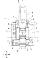
図1は、本発明の実施の形態による回転打撃工具の一例であるオイルパルスドライバ1の全体を示す部分断面側面図であり、オイルパルスドライバ1に電池パックPを装着した状態を示している。オイルパルスドライバ1は、木ネジ、ボルト等に対して締付作業を行う工具である。図1に示されているように、オイルパルスドライバ1は、ハウジング2、ブラシレスモータ3、円環基板4、減速機構5、オイルパルスユニット6及び制御基板部7を備えている。なお、図1において、矢印で示された「前」を前方向、「後」を後方向、「上」を上方向、「下」を下方向と定義する。さらに、オイルパルスドライバ1を後方から見た場合の左を左方向、右を右方向と定義する。
FIG. 1 is a partial sectional side view showing an entire oil pulse driver 1 which is an example of a rotary impact tool according to an embodiment of the present invention, and shows a state where a battery pack P is mounted on the oil pulse driver 1. The oil pulse driver 1 is a tool that performs a tightening operation on wood screws, bolts, and the like. As shown in FIG. 1, the oil pulse driver 1 includes a housing 2, a brushless motor 3, an annular substrate 4, a speed reduction mechanism 5, an oil pulse unit 6, and a control substrate unit 7. In FIG. 1, “front” indicated by an arrow is defined as a forward direction, “rear” is defined as a rear direction, “up” is defined as an upward direction, and “down” is defined as a downward direction. Further, when the oil pulse driver 1 is viewed from behind, the left is defined as the left direction and the right is defined as the right direction.
ハウジング2は、オイルパルスドライバ1の外郭をなしており、モータ収容部21と、ハンドル部22と、基板収容部23とを有している。
The housing 2 forms an outline of the oil pulse driver 1, and includes a motor housing portion 21, a handle portion 22, and a substrate housing portion 23.
モータ収容部21は、前後方向に延びる略筒形状をなし、その内部にブラシレスモータ3、円環基板4、減速機構5及びオイルパルスユニット6を収容している。また、モータ収容部21の前側内部には、機構ケース21Aが配置されている。機構ケース21Aは、前方に向かうに従って徐々に径が細くなる形状をなしており、その前端部分には開口21aが形成されている。
The motor accommodating portion 21 has a substantially cylindrical shape extending in the front-rear direction, and accommodates the brushless motor 3, the annular substrate 4, the speed reduction mechanism 5, and the oil pulse unit 6 therein. Further, a mechanism case 21 </ b> A is disposed inside the front side of the motor housing portion 21. The mechanism case 21A has a shape that gradually decreases in diameter toward the front, and an opening 21a is formed at the front end portion thereof.
ブラシレスモータ3は、モータ収容部21の後部に収容されており、回転軸31と、ロータ32と、ステータ33とを有している。回転軸31は、前後方向に延びる軸であって、軸受を介してモータ収容部21に回転可能に支承されている。また、回転軸31の前部には、冷却ファン31Aが設けられている。冷却ファン31Aは、遠心ファンであり、回転軸31の回転により回転し、モータ収容部21内にブラシレスモータ3、円環基板4等を冷却する冷却風を発生させる。ロータ32は、複数の永久磁石32Aを有する回転子であり、回転軸31に固定されており、回転軸31と一体回転するように構成されている。ステータ33は、ステータ巻線33Aを有する固定子であり、モータ収容部21に固定されている。ブラシレスモータ3の電気的構成の詳細については、後述する。ブラシレスモータ3は、本発明における「モータ」の一例である。
The brushless motor 3 is accommodated in the rear portion of the motor accommodating portion 21, and includes a rotating shaft 31, a rotor 32, and a stator 33. The rotating shaft 31 is a shaft extending in the front-rear direction, and is rotatably supported by the motor housing portion 21 via a bearing. A cooling fan 31 </ b> A is provided at the front portion of the rotating shaft 31. The cooling fan 31 </ b> A is a centrifugal fan, and is rotated by the rotation of the rotating shaft 31 to generate cooling air that cools the brushless motor 3, the annular substrate 4, and the like in the motor housing portion 21. The rotor 32 is a rotor having a plurality of permanent magnets 32 </ b> A, is fixed to the rotating shaft 31, and is configured to rotate integrally with the rotating shaft 31. The stator 33 is a stator having a stator winding 33 </ b> A, and is fixed to the motor housing portion 21. Details of the electrical configuration of the brushless motor 3 will be described later. The brushless motor 3 is an example of the “motor” in the present invention.
円環基板4は、後面視において円環形状をなす基板であって、ブラシレスモータ3のステータ33の後方に配置されている。また、円環基板4の後面視中央には前後方向に貫通する挿通孔が形成されており、当該挿通孔には回転軸31の後部が挿通されている。円環基板4の電気的構成の詳細については、後述する。
The annular substrate 4 is an annular substrate in a rear view, and is disposed behind the stator 33 of the brushless motor 3. Further, an insertion hole penetrating in the front-rear direction is formed in the center of the annular substrate 4 as viewed from the rear, and the rear portion of the rotating shaft 31 is inserted through the insertion hole. Details of the electrical configuration of the annular substrate 4 will be described later.
減速機構5は、ブラシレスモータ3の回転軸31(ロータ32)の回転を減速してオイルパルスユニット6に伝達する遊星ギヤ機構である。減速機構5は、回転軸31と一体回転するサンギヤ5Aと、サンギヤ5Aに噛合する遊星ギヤ5Bと、遊星ギヤ5Bと噛合するとともにモータ収容部21に対して固定されたリングギア5Cと、遊星ギヤ5B及びオイルパルスユニット6に接続されるとともに回転軸31と同軸回転するように構成されたキャリア5Dとを備えている。回転軸31の回転は、サンギヤ5Aを介して遊星ギヤ5Bの周回運動に変換され、当該周回運動はキャリア5Dを介してオイルパルスユニット6に伝達される。これにより、回転軸31の回転は、減速されてオイルパルスユニット6に伝達される。
The reduction mechanism 5 is a planetary gear mechanism that decelerates the rotation of the rotation shaft 31 (rotor 32) of the brushless motor 3 and transmits it to the oil pulse unit 6. The speed reduction mechanism 5 includes a sun gear 5A that rotates integrally with the rotation shaft 31, a planetary gear 5B that meshes with the sun gear 5A, a ring gear 5C that meshes with the planetary gear 5B and is fixed to the motor housing portion 21, and a planetary gear. 5B and a carrier 5D connected to the oil pulse unit 6 and configured to rotate coaxially with the rotary shaft 31. The rotation of the rotating shaft 31 is converted into the orbiting motion of the planetary gear 5B via the sun gear 5A, and the orbiting motion is transmitted to the oil pulse unit 6 via the carrier 5D. Thereby, the rotation of the rotating shaft 31 is decelerated and transmitted to the oil pulse unit 6.
オイルパルスユニット6は、ブラシレスモータ3の回転軸31(ロータ32)の回転力を間欠的な回転打撃力に変換して出力する機構であり、機構ケース21Aの内部に収容されている。オイルパルスユニット6は、減速機構5に接続されたライナ部6Aと図示せぬ先端ビットを保持可能な打撃軸部6Bとを備えている。オイルパルスユニット6においては、ライナ部6Aを打撃軸部6Bに対して回転させることで、先端ビットを保持した打撃軸部6Bに間欠的な回転打撃力を発生させる。オイルパルスドライバ1においては、当該間欠的な回転打撃力を用いて木ネジ、ボルト等に対する締付作業を行う。本実施の形態において、先端ビットは、ドライバビットやボルト締付用ビット等である。オイルパルスユニット6の詳細については、後述する。
The oil pulse unit 6 is a mechanism that converts the rotational force of the rotating shaft 31 (rotor 32) of the brushless motor 3 into an intermittent rotational striking force and outputs it, and is housed inside the mechanism case 21A. The oil pulse unit 6 includes a liner portion 6A connected to the speed reduction mechanism 5 and a striking shaft portion 6B capable of holding a tip bit (not shown). In the oil pulse unit 6, by rotating the liner portion 6A with respect to the striking shaft portion 6B, intermittent rotational striking force is generated in the striking shaft portion 6B holding the tip bit. In the oil pulse driver 1, a tightening operation for wood screws, bolts and the like is performed using the intermittent rotational impact force. In the present embodiment, the tip bit is a driver bit, a bolt tightening bit, or the like. Details of the oil pulse unit 6 will be described later.
ハンドル部22は、モータ収容部21の前後方向略中央から下方に延びる部分であり、ユーザによって把持される部分である。ハンドル部22は、ユーザによって操作可能に構成されたスイッチトリガ22Aとスイッチ機構22Bとを備えている。スイッチトリガ22Aは、ハンドル部22の上端部前側に設けられており、ハンドル部22内部においてスイッチ機構22Bと接続されている。スイッチ機構22Bは、制御基板部7に接続されており、スイッチトリガ22Aが押込まれた場合(オンされた場合)、始動信号を制御基板部7に出力する。
The handle portion 22 is a portion that extends downward from approximately the center in the front-rear direction of the motor housing portion 21 and is a portion that is gripped by the user. The handle portion 22 includes a switch trigger 22A and a switch mechanism 22B configured to be operable by a user. The switch trigger 22 </ b> A is provided in front of the upper end of the handle portion 22 and is connected to the switch mechanism 22 </ b> B inside the handle portion 22. The switch mechanism 22B is connected to the control board unit 7 and outputs a start signal to the control board unit 7 when the switch trigger 22A is pushed (turned on).
基板収容部23は、ハンドル部22の下端に接続されており、その内部に制御基板部7を収容している。基板収容部23の下端部には、電池パックPを着脱可能に保持するように構成された電池接続部23Aが形成されている。電池接続部23Aは、プラス接続端子23B及びマイナス接続端子23C(図6)を有している。制御基板部7の電気的構成の詳細については、後述する。
The board housing part 23 is connected to the lower end of the handle part 22 and houses the control board part 7 therein. A battery connection portion 23 </ b> A configured to detachably hold the battery pack P is formed at the lower end portion of the substrate housing portion 23. The battery connection portion 23A has a positive connection terminal 23B and a negative connection terminal 23C (FIG. 6). Details of the electrical configuration of the control board 7 will be described later.
電池パックPは、ブラシレスモータ3、円環基板4及び制御基板部7の電源となる二次電池を有する電池組を収容している。電池組は、電池パックPが電池接続部23Aに装着(接続)された状態で、プラス接続端子23B及びマイナス接続端子23Cに接続されるように構成されている。本実施の形態において、二次電池は、リチウムイオン二次電池である。
The battery pack P accommodates a battery set having a secondary battery serving as a power source for the brushless motor 3, the annular substrate 4 and the control substrate unit 7. The battery set is configured to be connected to the plus connection terminal 23B and the minus connection terminal 23C in a state where the battery pack P is mounted (connected) to the battery connection portion 23A. In the present embodiment, the secondary battery is a lithium ion secondary battery.
ここで、図2~図4を参照しながらオイルパルスユニット6の詳細について説明する。図2は、オイルパルスユニット6を示す図1の部分拡大図である。図3は、オイルパルスユニット6を示す図2のIII-III断面図である。なお、説明の便宜上、図3(a)に示されている状態を打撃軸部6Bに対するライナ部6Aの相対回転角度が0°の状態と定義する。図3(b)に示されている状態は、打撃軸部6Bに対するライナ部6Aの相対回転角度が180°の状態である。また、図2及び図3に示されている回転軸心Aは、回転軸31(キャリア5D)の回転軸心を表わしている。
Here, the details of the oil pulse unit 6 will be described with reference to FIGS. FIG. 2 is a partially enlarged view of FIG. 1 showing the oil pulse unit 6. 3 is a cross-sectional view of the oil pulse unit 6 taken along the line III-III in FIG. For convenience of explanation, the state shown in FIG. 3A is defined as a state in which the relative rotation angle of the liner portion 6A with respect to the striking shaft portion 6B is 0 °. The state shown in FIG. 3B is a state in which the relative rotation angle of the liner portion 6A with respect to the striking shaft portion 6B is 180 °. 2 and 3 represents the rotation axis of the rotation shaft 31 (carrier 5D).
図2に示されているように、オイルパルスユニット6のライナ部6Aは、前後方向に延びる筒形状をなす主筒状部61と、主筒状部61の後部を閉塞する接続プレート62と、主筒状部61の前端に設けられた先端筒状部63とを備えており、回転軸心Aを中心に回転可能に設けられている。また、図3(a)及び(b)に示されているように、ライナ部6Aの内部には、主筒状部61の内周面等によってライナ室61aが画成されており、ライナ室61aにはオイル(作動油)が充填されている。
As shown in FIG. 2, the liner portion 6A of the oil pulse unit 6 includes a main cylindrical portion 61 having a cylindrical shape extending in the front-rear direction, a connection plate 62 for closing the rear portion of the main cylindrical portion 61, A front end cylindrical portion 63 provided at the front end of the main cylindrical portion 61, and is provided so as to be rotatable about the rotation axis A. Further, as shown in FIGS. 3A and 3B, a liner chamber 61a is defined inside the liner portion 6A by an inner peripheral surface of the main cylindrical portion 61, and the liner chamber. 61a is filled with oil (hydraulic oil).
図3(a)及び(b)に示されているように、主筒状部61の内周面は、後面視において略楕円形状を規定しており、当該内周面には、第1凸部61A、第2凸部61B、第1突起61C及び第2突起61Dが形成されている。なお、図3(a)及び(b)においては、主筒状部61の内周面が規定する略楕円形状の長軸を仮想長軸線X-Xで示し、短軸を仮想短軸線Y-Yで示している。
As shown in FIGS. 3A and 3B, the inner peripheral surface of the main cylindrical portion 61 defines a substantially elliptical shape in the rear view, and the inner peripheral surface has a first protrusion. A portion 61A, a second protrusion 61B, a first protrusion 61C, and a second protrusion 61D are formed. 3A and 3B, the major axis of the substantially elliptic shape defined by the inner peripheral surface of the main cylindrical portion 61 is indicated by a virtual major axis XX, and the minor axis is a virtual minor axis Y-. Y is shown.
第1凸部61Aは、主筒状部61の内周面から主筒状部61の径方向内方に突出するとともに前後方向に延びており、後面視において仮想長軸線X-X上に位置している。第2凸部61Bは、第1凸部61Aと同一形状をなしており、回転軸心Aに関して第1凸部61Aと対称に構成されている。
The first convex portion 61A protrudes from the inner peripheral surface of the main cylindrical portion 61 inward in the radial direction of the main cylindrical portion 61 and extends in the front-rear direction, and is positioned on the virtual long axis XX in the rear view. is doing. The second convex portion 61B has the same shape as the first convex portion 61A, and is configured symmetrically with the first convex portion 61A with respect to the rotation axis A.
第1突起61Cは、主筒状部61の内周面から主筒状部61の径方向内方に突出するとともに前後方向に延びており、後面視において仮想短軸線Y-Yよりも僅かに第1凸部61A側に位置している。第2突起61Dは、第1突起61Cと同一形状をなしており、仮想長軸線X-Xを含み仮想短軸線Y-Yに直交する仮想平面に関して、第1突起61Cと対称に構成されている。第1突起61C及び第2突起61Dは、図3(a)に示されている状態(相対回転角度0°)では後面視において仮想短軸線Y-Yよりも僅かに上方に位置し、図3(b)に示されている状態(相対回転角度180°)では、仮想短軸線Y-Yよりも僅かに下方に位置する。
The first protrusion 61C protrudes from the inner peripheral surface of the main cylindrical portion 61 inward in the radial direction of the main cylindrical portion 61 and extends in the front-rear direction, and is slightly smaller than the virtual short axis YY in the rear view. It is located on the first convex portion 61A side. The second protrusion 61D has the same shape as the first protrusion 61C, and is configured symmetrically with the first protrusion 61C with respect to a virtual plane that includes the virtual long axis XX and is orthogonal to the virtual short axis YY. . In the state shown in FIG. 3A (relative rotation angle 0 °), the first protrusion 61C and the second protrusion 61D are positioned slightly above the virtual short axis YY in the rear view, and FIG. In the state shown in (b) (relative rotation angle 180 °), it is located slightly below the virtual short axis YY.
図2に戻り、接続プレート62は、円板部62A及び接続部62Bを備えている。円板部62Aは、主筒状部61の後部を閉塞する部分であり、後面視において円形状をなしている。円板部62Aの前面には、後方に窪む軸受孔62aが形成されている。接続部62Bは、前後方向に延びる略六角注形状をなしており、円板部62Aの後面の略中央に固定されるとともに減速機構5のキャリア5Dに相対回転不能に接続されている。これにより、ライナ部6Aは、キャリア5Dと一体に回転軸心Aを中心に回転する。
Returning to FIG. 2, the connection plate 62 includes a disc part 62 </ b> A and a connection part 62 </ b> B. The disc part 62A is a part that closes the rear part of the main cylindrical part 61, and has a circular shape in a rear view. A bearing hole 62a that is recessed rearward is formed in the front surface of the disc portion 62A. The connecting portion 62B has a substantially hexagonal shape extending in the front-rear direction, is fixed to the approximate center of the rear surface of the disc portion 62A, and is connected to the carrier 5D of the speed reduction mechanism 5 so as not to be relatively rotatable. Thereby, the liner part 6A rotates around the rotation axis A integrally with the carrier 5D.
先端筒状部63は、主筒状部61と連続した部分であり、主筒状部61の前端から前方に延びる筒形状をなしている。先端筒状部63の外径は、主筒状部61の外径よりも小さく構成されており、先端筒状部63の前端には、開口63aが形成されている。
The distal cylindrical portion 63 is a portion that is continuous with the main cylindrical portion 61 and has a cylindrical shape that extends forward from the front end of the main cylindrical portion 61. The outer diameter of the distal tubular portion 63 is configured to be smaller than the outer diameter of the main tubular portion 61, and an opening 63 a is formed at the front end of the distal tubular portion 63.
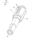
図2~図4に示されているように、オイルパルスユニット6の打撃軸部6Bは、メインシャフト64と、第1ブレード65と、第2ブレード66とを備えている。図4は、メインシャフト64を示す斜視図である。
As shown in FIGS. 2 to 4, the striking shaft portion 6B of the oil pulse unit 6 includes a main shaft 64, a first blade 65, and a second blade 66. FIG. 4 is a perspective view showing the main shaft 64.
図2及び図4に示されているように、メインシャフト64は、前後方向に延びる略円柱形状の軸であり、その前部はライナ部6Aの開口63a及び機構ケース21Aの開口21a(図1)を介して前方に突出しており、後部は、ライナ室61a内に収容されている。また、メインシャフト64の前部には、先端ビットが挿入される保持孔64aが前端から後方に窪むように形成されており、後端部は、ライナ部6Aの軸受孔62aに挿通されている。さらに、メインシャフト64の前後方向略中央部分とライナ部6Aの先端筒状部63の内周面との間には、ゴム製のOリング64Aが設けられている。すなわち、メインシャフト64は、軸受孔62aを介して、ライナ部6Aに回転可能に支承されており、Oリング64Aによってオイルパルスユニット6内部のオイルが外部に漏れるのを防いでいる。なお、メインシャフト64の回転軸心は、回転軸心Aと略一致している。
As shown in FIGS. 2 and 4, the main shaft 64 is a substantially cylindrical shaft extending in the front-rear direction, and the front portion thereof has an opening 63a of the liner portion 6A and an opening 21a of the mechanism case 21A (FIG. 1). ) And the rear part is accommodated in the liner chamber 61a. Further, a holding hole 64a into which the front end bit is inserted is formed in the front portion of the main shaft 64 so as to be recessed backward from the front end, and the rear end portion is inserted into the bearing hole 62a of the liner portion 6A. Further, a rubber O-ring 64A is provided between the substantially central portion of the main shaft 64 in the front-rear direction and the inner peripheral surface of the tip cylindrical portion 63 of the liner portion 6A. That is, the main shaft 64 is rotatably supported by the liner portion 6A via the bearing hole 62a, and the oil inside the oil pulse unit 6 is prevented from leaking to the outside by the O-ring 64A. The rotation axis of the main shaft 64 substantially coincides with the rotation axis A.
また、図3及び図4に示されているように、ライナ室61a内に収容されたメインシャフト64の後部には、前後方向に延びるとともにメインシャフト64の中心(回転軸心A)を通るように径方向に貫通するシャフト貫通孔64bが形成されている。また、メインシャフト64の後部外周面には、メインシャフト64の径方向外方に突出するとともに前後方向に延びる第1シール凸部64B、第2シール凸部64C、第3シール凸部64D及び第4シール凸部64Eが形成されている。
As shown in FIGS. 3 and 4, the rear portion of the main shaft 64 accommodated in the liner chamber 61a extends in the front-rear direction and passes through the center of the main shaft 64 (rotation axis A). A shaft through hole 64b penetrating in the radial direction is formed. Further, on the outer peripheral surface of the rear portion of the main shaft 64, a first seal convex portion 64B, a second seal convex portion 64C, a third seal convex portion 64D, and a first seal convex portion 64D that protrude radially outward of the main shaft 64 and extend in the front-rear direction. A four-seal projection 64E is formed.
第1シール凸部64Bは、図3(a)の状態(相対回転角度0°)においてライナ部6Aの第1突起61C対向する位置に形成されている。第2シール凸部64Cは、第1シール凸部64Bと同一形状をなしており、図3(a)の状態において、ライナ部6Aの第2突起61Dと対向する位置に形成されている。なお、第1シール凸部64B及び第2シール凸部64Cが第1突起61C及び第2突起61Dにそれぞれ対向している状態において、それらの間には僅かな隙間が形成されている。
The first seal convex portion 64B is formed at a position facing the first protrusion 61C of the liner portion 6A in the state of FIG. 3A (relative rotation angle 0 °). The second seal convex portion 64C has the same shape as the first seal convex portion 64B, and is formed at a position facing the second protrusion 61D of the liner portion 6A in the state of FIG. In the state where the first seal convex portion 64B and the second seal convex portion 64C are opposed to the first protrusion 61C and the second protrusion 61D, a slight gap is formed between them.
第3シール凸部64Dは、図3(b)の状態(相対回転角度180°)において第1突起61Cと対向する位置に形成されている。第4シール凸部64Eは、図3(b)の状態において第2突起61Dと対向する位置に形成されている。なお、第3シール凸部64D及び第4シール凸部64Eが第1突起61C及び第2突起61Dにそれぞれ対向している状態において、それらの間には僅かな隙間が形成されている。
The third seal protrusion 64D is formed at a position facing the first protrusion 61C in the state shown in FIG. 3B (relative rotation angle 180 °). The fourth seal convex portion 64E is formed at a position facing the second protrusion 61D in the state of FIG. In the state where the third seal convex portion 64D and the fourth seal convex portion 64E are opposed to the first protrusion 61C and the second protrusion 61D, a slight gap is formed between them.
図2及び図3に示されているように、第1ブレード65及び第2ブレード66は、前後方向に延びる略板形状をなす同一の部材であり、シャフト貫通孔64b内にメインシャフト64の径方向に往復動可能に設けられている。第1ブレード65と第2ブレード66との間には、スプリング67が設けられており、スプリング67は第1ブレード65及び第2ブレード66をメインシャフト64の径方向外方に付勢している。図3(a)の状態において、第1ブレード65の径方向外方端はライナ部6Aの第1凸部61Aに、第2ブレード66の径方向外方端は第2凸部61Bに当接した状態となる。また、図3(b)の状態において、第1ブレード65の径方向外方端はライナ部6Aの第2凸部61Bに、第2ブレード66の径方向外方端は第1凸部61Aに当接した状態となる。
As shown in FIGS. 2 and 3, the first blade 65 and the second blade 66 are the same member having a substantially plate shape extending in the front-rear direction, and the diameter of the main shaft 64 in the shaft through hole 64b. It is provided so that it can reciprocate in the direction. A spring 67 is provided between the first blade 65 and the second blade 66, and the spring 67 biases the first blade 65 and the second blade 66 outward in the radial direction of the main shaft 64. . In the state of FIG. 3A, the radially outer end of the first blade 65 is in contact with the first convex portion 61A of the liner portion 6A, and the radially outer end of the second blade 66 is in contact with the second convex portion 61B. It will be in the state. Further, in the state of FIG. 3B, the radially outer end of the first blade 65 is the second convex portion 61B of the liner portion 6A, and the radially outer end of the second blade 66 is the first convex portion 61A. It comes into contact.
ここで、図5を参照しながら、オイルパルスユニット6の動作及びオイルパルスユニット6における間欠的な回転打撃力の発生について説明する。図5は、オイルパルスユニット6の動作を示す図であり、(a)はライナ部6Aと打撃軸部6Bとの相対回転角度が0°の場合、(b)は45°の場合、(c)は90°の場合、(d)は135°の場合、(e)は180°の場合、(f)は225°の場合、(g)は270°の場合、(h)は315°の場合を示している。なお、図5中の回転方向R(矢印)は、ライナ部6Aの回転方向(後面視において時計回り方向)を示している。
Here, the operation of the oil pulse unit 6 and the generation of intermittent rotational impact force in the oil pulse unit 6 will be described with reference to FIG. 5A and 5B are diagrams showing the operation of the oil pulse unit 6. FIG. 5A shows a case where the relative rotation angle between the liner portion 6A and the striking shaft portion 6B is 0 °, FIG. ) Is 90 °, (d) is 135 °, (e) is 180 °, (f) is 225 °, (g) is 270 °, (h) is 315 ° Shows the case. In addition, the rotation direction R (arrow) in FIG. 5 has shown the rotation direction (clockwise direction in rear view) of the liner part 6A.
ブラシレスモータ3が駆動し、回転軸31の回転が減速機構5を介してオイルパルスユニット6に伝達されると、ライナ部6Aが回転方向Rに回転を開始する。このとき、打撃軸部6Bのメインシャフト64に負荷がかかっていない場合又は負荷が小さい場合(例えば、締付作業開始から木ネジ、ボルト等が着座するまでの期間)には、ライナ室61aに充填されたオイルの抵抗のみでライナ部6Aと打撃軸部6Bとが一体に回転する。
When the brushless motor 3 is driven and the rotation of the rotation shaft 31 is transmitted to the oil pulse unit 6 via the speed reduction mechanism 5, the liner portion 6A starts to rotate in the rotation direction R. At this time, when no load is applied to the main shaft 64 of the striking shaft portion 6B or when the load is small (for example, a period from the start of the tightening operation to the seating of wood screws, bolts, etc.), the liner chamber 61a The liner portion 6A and the striking shaft portion 6B rotate integrally only with the resistance of the filled oil.
一方、メインシャフト64に大きな負荷がかかった場合(例えば、木ネジ、ボルト等が着座した場合)には、ライナ部6A及び打撃軸部6Bは一体に回転せず、ライナ部6Aのみが回転する。ライナ部6Aのみが回転を開始して、図5(a)の状態(相対回転角度が0°)となると、ライナ部6Aの第1突起61Cは打撃軸部6B(メインシャフト64)の第1シール凸部64Bと、第2突起61Dは第2シール凸部64Cと前後方向全域に亘って対向し、第1凸部61Aは第1ブレード65と、第2凸部61Bは第2ブレード66と前後方向全域に亘って当接する。これにより、ライナ室61aは、図5(a)に示されているように、ライナ分室61b、61c、61d、61eの4室に区画される「区画状態」となる。
On the other hand, when a large load is applied to the main shaft 64 (for example, when wood screws, bolts, etc. are seated), the liner portion 6A and the striking shaft portion 6B do not rotate integrally, but only the liner portion 6A rotates. . When only the liner portion 6A starts to rotate and reaches the state shown in FIG. 5A (relative rotation angle is 0 °), the first protrusion 61C of the liner portion 6A is the first of the striking shaft portion 6B (main shaft 64). The seal protrusion 64B and the second protrusion 61D face the second seal protrusion 64C across the entire front-rear direction, the first protrusion 61A is the first blade 65, and the second protrusion 61B is the second blade 66. Abuts over the entire front-rear direction. As a result, the liner chamber 61a is in a “partitioned state” that is partitioned into four chambers 61a, 61c, 61d, and 61e, as shown in FIG. 5A.
図5(a)の状態からブラシレスモータ3がさらに回転すると、ライナ分室61b及び61dの2室の容積が減少し、ライナ分室61b及び61d内のオイルが圧縮され、当該2室内のオイル圧が瞬間的に上昇する。この瞬間的なオイル圧の上昇によって、ライナ分室61b及び61dとライナ分室61c及び61eとの間に圧力差が生じ、第1ブレード65及び第2ブレード66それぞれの回転方向Rにおける上流側面が回転方向Rに押圧される。その結果、メインシャフト64を回転方向Rに回転させようとする回転力が瞬間的に発生し、メインシャフト64(打撃軸部6B)に強力な回転方向Rの回転打撃力(回転トルク)が発生する。なお、ライナ部6Aの主筒状部61には、上記の瞬間的に上昇するオイル圧を制御して締付トルクを調整するための図示せぬトルク調整機構が設けられている。
When the brushless motor 3 further rotates from the state of FIG. 5A, the volume of the two chambers 61b and 61d decreases, the oil in the liner chambers 61b and 61d is compressed, and the oil pressure in the two chambers instantaneously increases. Rises. This instantaneous increase in oil pressure causes a pressure difference between the liner compartments 61b and 61d and the liner compartments 61c and 61e, and the upstream side surfaces in the rotational direction R of the first blade 65 and the second blade 66 are in the rotational direction. Pressed by R. As a result, a rotational force for rotating the main shaft 64 in the rotational direction R is instantaneously generated, and a strong rotational impact force (rotational torque) in the rotational direction R is generated on the main shaft 64 (striking shaft portion 6B). To do. The main cylindrical portion 61 of the liner portion 6A is provided with a torque adjustment mechanism (not shown) for adjusting the tightening torque by controlling the oil pressure that rises instantaneously.
メインシャフト64に回転打撃力が発生した瞬間から、ライナ部6Aが打撃軸部6Bに対して相対的にさらに回転すると、第1シール凸部64Bが第1突起61Cに対向している状態、第2シール凸部64Cが第2突起61Dに対向している状態、第1ブレード65が第1凸部61Aと当接している状態、第2ブレード66が第2凸部61Bと当接している状態がそれぞれ解除される。これにより、4室に区画されていたライナ室61aの「区画状態」が解除されて「区画解除状態」となる。「区画解除状態」においては、ライナ室61a内のオイル圧が一定となり、第1ブレード65及び第2ブレード66に押圧力が働かないため、メインシャフト64には回転打撃力は発生せず、ライナ部6Aのみがさらに回転する。なお、ライナ室61aが「区画状態」となりメインシャフト64に回転打撃力が発生した瞬間から「区画解除状態」となるまでの期間、メインシャフト64には回転打撃力が発生している。
When the liner portion 6A further rotates relative to the striking shaft portion 6B from the moment when the rotational striking force is generated on the main shaft 64, the first seal convex portion 64B faces the first protrusion 61C, 2 The seal convex part 64C is facing the second protrusion 61D, the first blade 65 is in contact with the first convex part 61A, and the second blade 66 is in contact with the second convex part 61B Are released respectively. As a result, the “partition state” of the liner chamber 61a that has been partitioned into the four chambers is canceled and becomes the “partition release state”. In the “partition release state”, the oil pressure in the liner chamber 61a is constant, and no pressing force is applied to the first blade 65 and the second blade 66. Therefore, no rotational impact force is generated on the main shaft 64, and the liner Only the part 6A rotates further. It should be noted that during the period from the moment when the liner chamber 61 a is in the “partitioned state” and the rotational impact force is generated on the main shaft 64 to the “partition release state”, the rotational impact force is generated on the main shaft 64.
「区画解除状態」となった後、ライナ部6Aがさらに回転すると、「区画解除状態」を維持したまま、図5(b)の状態(相対回転角度45°)を経て、図5(c)の状態(相対回転角度90°)の状態となる。当該状態となると、第1ブレード65が第1突起61Cに当接し、第2ブレード66が第2突起61Dに当接する。これにより、第1ブレード65及び第2ブレード66が径方向内方に後退し、第1ブレード65及び第2ブレード66のメインシャフト64から径方向外方に突出していた部分がシャフト貫通孔64b内に全て収容される。このため、第1ブレード65及び第2ブレード66はオイル圧の影響を受けない状態となり、メインシャフト64に回転打撃力は発生せず、ライナ部6Aはそのまま回転する。
When the liner section 6A further rotates after entering the “compartment release state”, the state of FIG. 5B is maintained (relative rotation angle 45 °) while maintaining the “compartment release state”, and FIG. (A relative rotation angle of 90 °). In this state, the first blade 65 comes into contact with the first protrusion 61C, and the second blade 66 comes into contact with the second protrusion 61D. As a result, the first blade 65 and the second blade 66 are retracted radially inward, and the portions of the first blade 65 and second blade 66 that protrude radially outward from the main shaft 64 are in the shaft through hole 64b. Are all contained. For this reason, the first blade 65 and the second blade 66 are not affected by the oil pressure, and no rotational striking force is generated on the main shaft 64, and the liner portion 6A rotates as it is.
ライナ部6Aが図5(c)の状態からさらに回転すると、再び「区画解除状態」となり、図5(d)の状態(相対回転角度135°)を経て、図5(e)の状態(相対回転角度180°)となる。図5(e)の状態となると、ライナ部6Aの第1突起61Cは打撃軸部6B(メインシャフト64)の第3シール凸部64Dと、第2突起61Dは第4シール凸部64Eと前後方向全域に亘って対向し、第1凸部61Aは第2ブレード66と、第2凸部61Bは第1ブレード65と前後方向全域に亘って当接する。これにより、ライナ室61aは、図5(e)に示されているように、ライナ分室61b、61c、61d、61eの4室に再び区画され(「区画状態」)、当該状態からライナ部6Aが打撃軸部6Bに対してさらに回転すると、再び回転打撃力が発生する。
When the liner portion 6A further rotates from the state of FIG. 5C, the “partition release state” is entered again, and after the state of FIG. 5D (relative rotation angle 135 °), the state of FIG. Rotation angle 180 °). In the state of FIG. 5E, the first protrusion 61C of the liner portion 6A is the third seal protrusion 64D of the striking shaft portion 6B (main shaft 64), and the second protrusion 61D is the front and rear of the fourth seal protrusion 64E. The first convex portion 61A is in contact with the second blade 66 and the second convex portion 61B is in contact with the first blade 65 over the entire front-rear direction. Accordingly, as shown in FIG. 5E, the liner chamber 61a is partitioned again into four chambers 61a, 61c, 61d, 61e (“partition state”), and the liner portion 6A When the ball rotates further with respect to the striking shaft portion 6B, a rotational striking force is generated again.
当該回転打撃力が発生した後、さらにライナ部6Aが回転すると再び「区画解除状態」となり、図5(f)の状態(相対回転角度225°)を経て、図5(g)の状態(相対回転角度270°)となる。当該状態となると、第1突起61Cが第2ブレード66に当接し、第2突起61Dが第1ブレード65に当接し、再び、第1ブレード65及び第2ブレード66のメインシャフト64から径方向外方に突出していた部分がシャフト貫通孔64b内に全て収容される。このため、図5(c)の状態と同様に、第1ブレード65及び第2ブレード66はオイル圧の影響を受けない状態となり、メインシャフト64に回転打撃力は発生せず、ライナ部6Aはそのまま回転する。
After the rotation hitting force is generated, when the liner portion 6A further rotates, the “partition release state” occurs again, and after the state shown in FIG. 5F (relative rotation angle 225 °), the state shown in FIG. Rotation angle 270 °). In this state, the first protrusion 61C comes into contact with the second blade 66, the second protrusion 61D comes into contact with the first blade 65, and again from the main shaft 64 of the first blade 65 and the second blade 66 radially outward. The portion protruding in the direction is accommodated in the shaft through hole 64b. For this reason, as in the state of FIG. 5C, the first blade 65 and the second blade 66 are not affected by the oil pressure, and no rotational impact force is generated on the main shaft 64, and the liner portion 6A It rotates as it is.
ライナ部6Aが図5(g)の状態からさらに回転すると、再び「区画解除状態」となり、図5(h)の状態(相対回転角度315°)を経て、図5(a)の状態(相対回転角度0°)となる。この後、ライナ部6Aが回転を継続すると、上記の過程が繰返され、ライナ部6Aが打撃軸部6Bに対して1回転する毎(相対回転角度360°毎)に2回の回転打撃力(間欠的な回転打撃力)が発生する。当該間欠的に発生する回転打撃力により、メインシャフト64に保持された先端ビットが木ネジ、ボルト等を間欠的に回転方向Rに打撃(回転打撃)し、木ネジ、ボルト等が被締結材に対して締付けられる。このように、オイルパルスユニット6は、ブラシレスモータ3の回転軸31(ロータ32)の回転力を間欠的な回転打撃力に変換して出力し、当該間欠的な回転打撃力を用いて木ネジ、ボルト等に対して締付作業を行う。オイルパルスユニット6は、本発明における「打撃機構部」の一例である。また、先端ビットは、本発明における「先端工具」の一例である。メインシャフト64の前部に形成された先端ビットが挿入される保持孔64aは、本発明における「先端工具保持部」の一例である。
When the liner portion 6A further rotates from the state of FIG. 5G, the “partition release state” is entered again, and after the state of FIG. 5H (relative rotation angle 315 °), the state of FIG. (Rotation angle 0 °). Thereafter, when the liner portion 6A continues to rotate, the above-described process is repeated, and each time the liner portion 6A makes one rotation with respect to the striking shaft portion 6B (every relative rotation angle 360 °), the rotational striking force twice ( Intermittent rotational impact force) is generated. Due to the intermittently generated rotating impact force, the tip bit held on the main shaft 64 intermittently strikes (rotates) the wood screws, bolts, etc. in the rotational direction R, and the wood screws, bolts, etc. are fastened. Tightened against. In this way, the oil pulse unit 6 converts the rotational force of the rotating shaft 31 (rotor 32) of the brushless motor 3 into an intermittent rotational impact force, and outputs the intermittent rotational impact force. Tighten the bolts. The oil pulse unit 6 is an example of the “blow mechanism” in the present invention. The tip bit is an example of the “tip tool” in the present invention. The holding hole 64a into which the tip bit formed in the front portion of the main shaft 64 is inserted is an example of the “tip tool holding portion” in the present invention.
次に、図6を参照しながらオイルパルスドライバ1の電気的構成、すなわちブラシレスモータ3、円環基板4及び制御基板部7の電気的構成の詳細について説明する。図6は、オイルパルスドライバ1の電気的構成を示すブロック図を含む回路図である。
Next, details of the electrical configuration of the oil pulse driver 1, that is, the electrical configurations of the brushless motor 3, the annular substrate 4, and the control substrate unit 7 will be described with reference to FIG. FIG. 6 is a circuit diagram including a block diagram showing an electrical configuration of the oil pulse driver 1.
図6に示されているように、ブラシレスモータ3のロータ32は、N極及びS極を1組とした永久磁石32Aを2組備えている。また、ステータ33のステータ巻線33Aは、スター結線された3相のコイルU、V、Wを有し、コイルU、V、Wはそれぞれ円環基板4に接続されている。
As shown in FIG. 6, the rotor 32 of the brushless motor 3 includes two sets of permanent magnets 32 </ b> A each having a north pole and a south pole. The stator winding 33 </ b> A of the stator 33 has star-connected three-phase coils U, V, and W, and the coils U, V, and W are connected to the annular substrate 4.
円環基板4は、インバータ回路41及び3個のホールIC42を備えている。また、制御基板部7は、制御電源回路71、電流検出回路72、電圧検出回路73、回転位置検出回路74、回転数検出回路75、駆動信号出力回路76及び制御部77を備えている。
The annular substrate 4 includes an inverter circuit 41 and three Hall ICs 42. Further, the control board unit 7 includes a control power supply circuit 71, a current detection circuit 72, a voltage detection circuit 73, a rotation position detection circuit 74, a rotation number detection circuit 75, a drive signal output circuit 76, and a control unit 77.
インバータ回路41は、電池パックPの電力をブラシレスモータ3に供給する回路であり、プラス接続端子23B及びマイナス接続端子23Cとブラシレスモータ3との間に接続されている。インバータ回路41は、6個のスイッチング素子すなわちFET41A~41Fを有している。6個のFET41A~41Fは、3相ブリッジ形式に接続されており、各ゲートは駆動信号出力回路76に接続され、各ドレイン又は各ソースは、ブラシレスモータ3のコイルU、V、Wに接続されている。6個のFET41A~41Fは、ブラシレスモータ3に供給される電力(電圧)を切り替える。より詳細には、6個のFET41A~41Fは、駆動信号出力回路76から出力される駆動信号(ゲート信号)に基づいて、ロータ32を所定の回転方向に回転させるスイッチング動作を行う。3個のホールIC42のそれぞれは、円環基板4の前面のロータ32と対向する位置に設けられており、ロータ32の回転位置に応じてハイ信号又はロー信号を回転位置検出回路74に出力する。FET41A~41Fのうちいずれか一つのFETが、本発明における「スイッチング素子」の一例である。
The inverter circuit 41 is a circuit that supplies power from the battery pack P to the brushless motor 3, and is connected between the plus connection terminal 23 </ b> B and the minus connection terminal 23 </ b> C and the brushless motor 3. The inverter circuit 41 has six switching elements, that is, FETs 41A to 41F. The six FETs 41A to 41F are connected in a three-phase bridge form, each gate is connected to the drive signal output circuit 76, and each drain or each source is connected to the coils U, V, W of the brushless motor 3. ing. The six FETs 41A to 41F switch the power (voltage) supplied to the brushless motor 3. More specifically, the six FETs 41A to 41F perform a switching operation for rotating the rotor 32 in a predetermined rotation direction based on the drive signal (gate signal) output from the drive signal output circuit 76. Each of the three Hall ICs 42 is provided at a position facing the rotor 32 on the front surface of the annular substrate 4, and outputs a high signal or a low signal to the rotational position detection circuit 74 according to the rotational position of the rotor 32. . Any one of the FETs 41A to 41F is an example of the “switching element” in the present invention.
制御電源回路71は、各回路に制御電源を供給する定電圧電源回路である。本実施の形態においては、制御電源回路71は、プラス接続端子23B及びマイナス接続端子23C間の電圧(電池パックPの電圧)を5V(制御電圧)に変換し、各回路に印加するように構成されている。
The control power supply circuit 71 is a constant voltage power supply circuit that supplies control power to each circuit. In the present embodiment, the control power supply circuit 71 is configured to convert the voltage between the positive connection terminal 23B and the negative connection terminal 23C (voltage of the battery pack P) into 5V (control voltage) and apply it to each circuit. Has been.
電流検出回路72は、インバータ回路41とマイナス接続端子23Cとの間に設けられたシャント抵抗1Aの電圧降下値を取り込むことでブラシレスモータ3に流れる電流(モータ電流)を検出し、検出したモータ電流に応じた信号(電流値信号)を制御部77に出力する回路である。電流検出回路72は、本発明における「電流検出部」の一例である。
The current detection circuit 72 detects the current (motor current) flowing through the brushless motor 3 by taking in the voltage drop value of the shunt resistor 1A provided between the inverter circuit 41 and the minus connection terminal 23C, and detects the detected motor current. Is a circuit that outputs a signal (current value signal) corresponding to The current detection circuit 72 is an example of the “current detection unit” in the present invention.
電圧検出回路73は、プラス接続端子23Bとマイナス接続端子23Cとの間に接続されており、ブラシレスモータ3に印可される電圧(プラス接続端子23Bとマイナス接続端子23Cとの間に印加される電圧)の電圧を検出し、検出した電圧値を示す信号(電圧値信号)を制御部77に出力する回路である。
The voltage detection circuit 73 is connected between the plus connection terminal 23B and the minus connection terminal 23C, and is applied to the brushless motor 3 (the voltage applied between the plus connection terminal 23B and the minus connection terminal 23C). ) And outputs a signal (voltage value signal) indicating the detected voltage value to the control unit 77.
回転位置検出回路74は、3個のホールIC42のそれぞれから出力されたハイ信号又はロー信号に応じてロータ32の回転位置を検出し、検出した回転位置を示す信号(回転位置信号)を回転数検出回路75及び制御部77に出力する回路である。
The rotational position detection circuit 74 detects the rotational position of the rotor 32 according to a high signal or a low signal output from each of the three Hall ICs 42, and outputs a signal (rotational position signal) indicating the detected rotational position as the rotational speed. This circuit outputs the detection circuit 75 and the control unit 77.
回転数検出回路75は、回転位置検出回路74から出力される回転位置信号に基づいてロータ32の回転数を算出し、算出した回転数を示す信号(回転数信号)を制御部77に出力する回路である。
The rotation speed detection circuit 75 calculates the rotation speed of the rotor 32 based on the rotation position signal output from the rotation position detection circuit 74, and outputs a signal (rotation speed signal) indicating the calculated rotation speed to the control unit 77. Circuit.
駆動信号出力回路76は、6個のFET41A~41Fのそれぞれのゲート及び制御部77に接続されている。駆動信号出力回路76は、制御部77から出力された制御信号に基づいて6個のFET41A~41Fの各ゲートに駆動信号を出力する回路である。
The drive signal output circuit 76 is connected to the gates of the six FETs 41A to 41F and the control unit 77. The drive signal output circuit 76 is a circuit that outputs drive signals to the gates of the six FETs 41A to 41F based on the control signal output from the control unit 77.
制御部77は、ブラシレスモータ3の駆動制御に用いる処理プログラム、各種データに基づいて演算を行う中央処理装置(CPU)を有する図示せぬ演算部と、当該処理プログラム、各種データ、各種閾値等を記憶するための図示せぬROMと、データを一時記憶するための図示せぬRAMを有する記憶部と、時間を計測する計時部とを備えている。なお、本実施の形態において、制御部77はマイクロコンピューターである。
The control unit 77 includes a processing program used for driving control of the brushless motor 3, a calculation unit (not shown) having a central processing unit (CPU) that performs calculation based on various data, the processing program, various data, various threshold values, and the like. A ROM (not shown) for storing, a storage unit having a RAM (not shown) for temporarily storing data, and a time measuring unit for measuring time are provided. In the present embodiment, the control unit 77 is a microcomputer.
制御部77は、回転位置検出回路74から出力された回転位置信号に基づいて、FET41A~41Fのうちの導通させるFETを交互に切換えるための制御信号を形成し、当該制御信号を駆動信号出力回路76に出力する。これによってコイルU、V、Wのうちの所定のコイルに交互に通電し、ロータ32を所定の回転方向に回転させる。この場合、インバータ回路41の負電源側(マイナスライン)に接続されているFET41D~41Fを駆動する(導通させる)駆動信号は、パルス幅変調信号(PWM駆動信号)として出力される。なお、PWM駆動信号は、デューティ比を変更可能な信号である。パルス幅変調(PWM制御)においては、パルスの幅であるデューティ比の大きさを切り替えることで出力される平均電圧を切り替える。デューティ比を大きくすればブラシレスモータ3に供給(印加)される平均電圧が大きくなり、デューティ比を小さくすればブラシレスモータ3に供給(印加)される平均電圧が小さくなる。パルス幅変調(PWM制御)によってブラシレスモータ3に供給される平均電圧は、本発明における「モータに供給される電圧」の一例である。制御部77は、本発明における「制御部」の一例である。
Based on the rotational position signal output from the rotational position detection circuit 74, the control unit 77 forms a control signal for alternately switching the FET to be conducted among the FETs 41A to 41F, and the control signal is output to the drive signal output circuit. Output to 76. As a result, a predetermined coil among the coils U, V, and W is alternately energized to rotate the rotor 32 in a predetermined rotation direction. In this case, a drive signal for driving (conducting) the FETs 41D to 41F connected to the negative power supply side (minus line) of the inverter circuit 41 is output as a pulse width modulation signal (PWM drive signal). The PWM drive signal is a signal whose duty ratio can be changed. In pulse width modulation (PWM control), the average voltage output is switched by switching the magnitude of the duty ratio, which is the pulse width. If the duty ratio is increased, the average voltage supplied (applied) to the brushless motor 3 is increased, and if the duty ratio is decreased, the average voltage supplied (applied) to the brushless motor 3 is decreased. The average voltage supplied to the brushless motor 3 by pulse width modulation (PWM control) is an example of the “voltage supplied to the motor” in the present invention. The control unit 77 is an example of the “control unit” in the present invention.
次に、制御部77によるブラシレスモータ3の駆動制御について説明する。
Next, drive control of the brushless motor 3 by the control unit 77 will be described.
制御部77によるブラシレスモータ3の駆動制御においては、モータ電流に基づいてデューティ比を変更することでモータ電流が目標電流値となるように制御する定電流制御を行い、所定の電流閾値(電流閾値I2)を超えた場合、着座時にブラシレスモータ3(ライナ部6A)に過大な負荷がかかるボルトのような締結部材が被締結材に着座したと判断し、ボルト着座後専用の制御(後述のS108~S110)を行う。
In the drive control of the brushless motor 3 by the control unit 77, constant current control is performed so that the motor current becomes the target current value by changing the duty ratio based on the motor current, and a predetermined current threshold value (current threshold value). If I2) is exceeded, it is determined that a fastening member such as a bolt that places an excessive load on the brushless motor 3 (liner portion 6A) at the time of seating is seated on the material to be fastened. To S110).
本実施の形態においては、ブラシレスモータ3及びFET41A~41Fの耐熱温度等を考慮し、回転打撃中以外におけるモータ電流の目標電流値を中心とした上下動の最大値が、ブラシレスモータ3及びFET41A~41Fの過度な温度上昇を招かない程度の電流値となるように(過度な温度上昇を招く電流値に達しないように)、目標電流値を設定している。なお、本実施の形態において、目標電流値は25Aであるが、これに限られず、使用されるモータ及びスイッチング素子の耐熱温度等を考慮して、モータ電流が過度な温度上昇を招かない程度の電流値となるように設定すればよい。
In the present embodiment, considering the heat-resistant temperature of the brushless motor 3 and the FETs 41A to 41F, etc., the maximum value of the vertical movement centered on the target current value of the motor current when not in rotation hitting is the brushless motor 3 and the FETs 41A to 41F. The target current value is set so that the current value does not cause an excessive temperature increase of 41 F (so as not to reach a current value that causes an excessive temperature increase). In the present embodiment, the target current value is 25 A, but is not limited to this, and the motor current does not cause an excessive temperature rise in consideration of the heat resistance temperature of the motor and the switching element used. What is necessary is just to set so that it may become an electric current value.
また、制御部77による定電流制御においては、ゲインが高く設定されたPIDフィードバック制御のような制御は行わずに、デューティ比を変更する処理毎にデューティ比を指定量増加又は減少させる。本実施の形態においては、上記した指定量は1%であり、制御部77によるデューティ比変更処理は略1ms毎に行われる。このため、モータ電流の目標電流値への追従性は、ゲインが高く設定されたPIDフィードバック制御等に比べて遅く、モータ電流は目標電流値を中心として緩やかに上下動する。
In the constant current control by the control unit 77, the duty ratio is increased or decreased by a specified amount every time the duty ratio is changed without performing control such as PID feedback control in which the gain is set high. In the present embodiment, the specified amount is 1%, and the duty ratio changing process by the control unit 77 is performed approximately every 1 ms. For this reason, the followability of the motor current to the target current value is slower than that of PID feedback control or the like with a high gain, and the motor current gently moves up and down around the target current value.
このように、ゲインが高く設定されたPIDフィードバック制御等に比べて目標電流値に対しての追従性を低く構成したのは、締付性能の低下を抑制しつつ且つボルト着座を確実に判断するためである。詳細には、仮に、目標電流値への追従性が高い定電流制御を行った場合には、回転打撃時に発生する急激なモータ電流の上昇に対して、急激にデューティ比を減少させてしまい締付性能が低下してしまう。これに対し、本実施の形態における追従性を低く構成した定電流制御を用いれば、急激にデューティ比を減少させることがなく締付性能の低下を抑制することができる。
As described above, the low follow-up performance with respect to the target current value compared to the PID feedback control or the like set with a high gain makes it possible to reliably determine the bolt seating while suppressing a decrease in the tightening performance. Because. More specifically, if constant current control with high follow-up to the target current value is performed, the duty ratio is suddenly reduced and tightened against the sudden increase in motor current that occurs at the time of rotational impact. Attaching performance will decrease. On the other hand, if constant current control with low followability in the present embodiment is used, it is possible to suppress a decrease in tightening performance without rapidly decreasing the duty ratio.
また、仮に、目標電流値への追従性の高い定電流制御を用いた場合には、ボルトが被締結材に着座した後にモータ電流の急激な上昇に応答してデューティ比を急激に減少させてしまう。このため、モータ電流が電流閾値I2を超える前にモータ電流を目標電流値付近まで低下させてしまい、ボルト着座を確実に判断(判別)することができない。これに対し、本実施の形態における追従性を低く構成した定電流制御を用いれば、ボルトが被締結材に着座した後の急激なモータ電流の上昇に対しても急激にデューティ比を減少させることがない。このため、モータ電流が電流閾値I2を超える前に、モータ電流を目標電流値付近まで低下させることがなく、確実にボルト着座を判断することができる。また、本実施の形態による定電流制御を行えば、モータ電流は目標電流値を中心として緩やかに上下動するため、モータ電流の変動(デューティ比の変更)に起因する締付フィーリングの悪化を抑制することもできる。なお、本実施の形態においては、デューティ比を変更する処理毎にデューティ比を指定量(1%)増加又は減少させる制御によって定電流制御の追従性を低く構成しているが、これに限られず、ゲインの値を適宜設定したPIDフィードバック制御等を用いて追従性を低く構成してもよい。
In addition, if constant current control with high follow-up to the target current value is used, the duty ratio is decreased rapidly in response to a rapid increase in motor current after the bolt is seated on the fastened material. End up. For this reason, before the motor current exceeds the current threshold value I2, the motor current is reduced to the vicinity of the target current value, and bolt seating cannot be determined (discriminated) reliably. On the other hand, if the constant current control with low followability in the present embodiment is used, the duty ratio can be reduced rapidly even with a sudden increase in motor current after the bolt is seated on the material to be fastened. There is no. For this reason, before the motor current exceeds the current threshold value I2, it is possible to reliably determine the bolt seating without reducing the motor current to near the target current value. In addition, if the constant current control according to the present embodiment is performed, the motor current gently moves up and down around the target current value, so that the tightening feeling caused by the fluctuation of the motor current (change of the duty ratio) is reduced. It can also be suppressed. In the present embodiment, the followability of constant current control is configured to be low by controlling the duty ratio to increase or decrease by a specified amount (1%) for each process of changing the duty ratio, but the present invention is not limited to this. The followability may be lowered by using PID feedback control or the like in which the gain value is appropriately set.
次に、制御部77による駆動制御における具体的な処理フローについて説明する。図7は、制御部77によるブラシレスモータ3の駆動制御を示すフローチャートである。
Next, a specific processing flow in drive control by the control unit 77 will be described. FIG. 7 is a flowchart showing drive control of the brushless motor 3 by the control unit 77.
制御部77は、電池パックPが電池接続部23Aに接続され、制御電源回路71から電源が供給された場合に駆動制御を開始する。制御部77は、駆動制御を開始すると、S101において、スイッチトリガ22Aがオンされたか否かを判断する。当該判断は、制御部77にスイッチ機構22Bから始動信号が入力されたか否かで判断し、制御部77に始動信号が入力された場合、スイッチトリガ22Aがオンされたと判断する。
The control unit 77 starts drive control when the battery pack P is connected to the battery connection unit 23 </ b> A and power is supplied from the control power supply circuit 71. When starting the drive control, the control unit 77 determines whether or not the switch trigger 22A is turned on in S101. This determination is made based on whether or not a start signal is input to the control unit 77 from the switch mechanism 22B. When the start signal is input to the control unit 77, it is determined that the switch trigger 22A is turned on.
S101で、スイッチトリガ22Aがオンされていないと判断した場合(S101:No)、S101の判断を再び行う。すなわち、S101の判断を繰返しながら、ユーザによってスイッチトリガ22Aがオンされるまで待機する。
If it is determined in S101 that the switch trigger 22A is not turned on (S101: No), the determination in S101 is performed again. That is, while the determination of S101 is repeated, the process waits until the switch trigger 22A is turned on by the user.
S101で、スイッチトリガ22Aがオンされたと判断した場合(S101:Yes)、ブラシレスモータ3の駆動を開始し、S102において、ブラシレスモータ3に流れる電流I(以下、モータ電流Iと呼ぶ)が電流閾値I1を超えているか否かを判断する。制御部77は、電流検出回路72が出力する電流値信号に基いてモータ電流Iを検出する。本実施の形態において、電流閾値I1は、上記したように25Aであり、定電流制御における目標電流値である。
When it is determined in S101 that the switch trigger 22A is turned on (S101: Yes), the driving of the brushless motor 3 is started, and in S102, a current I flowing through the brushless motor 3 (hereinafter referred to as a motor current I) is a current threshold value. It is determined whether or not I1 is exceeded. The controller 77 detects the motor current I based on the current value signal output from the current detection circuit 72. In the present embodiment, the current threshold value I1 is 25A as described above, and is a target current value in the constant current control.
S102で、モータ電流Iが電流閾値I1を超えていないと判断した場合(S102:No)、S103において、S103の処理時のデューティ比である処理時デューティ比D1が所定値D(本実施の形態においては、100%)未満であるか否かを判断する。
When it is determined in S102 that the motor current I does not exceed the current threshold value I1 (S102: No), in S103, the processing duty ratio D1, which is the duty ratio in the processing of S103, is a predetermined value D (this embodiment). It is determined whether or not it is less than 100%.
S103で、処理時デューティ比D1が所定値D未満であると判断した場合(S102:Yes)には、S104においてデューティ比を指定量(1%)増加させた後S102に戻り、処理時デューティ比D1が所定値D未満でないと判断した場合(S103:No)には、デューティ比は増加させずにS102に戻る。なお、デューティ比を1%増加させるとは、例えば、デューティ比が80%であれば81%にする意味であり、処理時デューティ比D1の1%分を増加させるという意味ではない。
If it is determined in S103 that the processing duty ratio D1 is less than the predetermined value D (S102: Yes), the duty ratio is increased by a specified amount (1%) in S104, and then the processing returns to S102, and the processing duty ratio If it is determined that D1 is not less than the predetermined value D (S103: No), the process returns to S102 without increasing the duty ratio. Note that increasing the duty ratio by 1% means, for example, that the duty ratio is 81% if the duty ratio is 80%, and does not mean that the processing duty ratio D1 is increased by 1%.
一方、S102で、モータ電流Iが電流閾値I1を超えていると判断した場合(S102:No)、S105において、モータ電流Iが電流閾値I2を超えているか否かを判断する。電流閾値I2は、被締結材に着座した締結部材の種類を判別するための閾値であり、モータ電流Iが電流閾値I2を超えている場合には、ネジ頭が被締結材に着座した場合にメインシャフト64に過大な負荷がかかるボルトのような締結部材であると判断し、一方、モータ電流Iが電流閾値I2を超えていない場合には、ネジ頭が被締結材に着座した後もメインシャフト64にかかる負荷は大きくなるものの締結部材が被締結材にのめりこんでいく木ネジのような締結部材であると判断する。電流閾値I2は、本発明における「判別閾値」の一例である。また、木ネジに対する締付作業は、本発明における「第1の作業」の一例である。さらに、ボルトに対する締付作業のうちボルトが着座する前の締付作業は、本発明における「第1の作業」の一例であり、ボルトに対する締付作業のうちボルトが着座した後の締付作業は、本発明における「第2の作業」の一例である。
On the other hand, when it is determined in S102 that the motor current I exceeds the current threshold I1 (S102: No), it is determined in S105 whether or not the motor current I exceeds the current threshold I2. The current threshold value I2 is a threshold value for determining the type of the fastening member seated on the fastened material. When the motor current I exceeds the current threshold value I2, the screw head is seated on the fastened material. If the main shaft 64 is determined to be a fastening member such as a bolt that applies an excessive load, on the other hand, if the motor current I does not exceed the current threshold I2, the main shaft 64 is also main after the screw head is seated on the material to be fastened. Although the load applied to the shaft 64 increases, it is determined that the fastening member is a fastening member such as a wood screw that is recessed into the material to be fastened. The current threshold I2 is an example of the “discrimination threshold” in the present invention. Further, the tightening operation for the wood screw is an example of the “first operation” in the present invention. Further, the tightening work before the bolt is seated in the tightening work for the bolt is an example of the “first work” in the present invention, and the tightening work after the bolt is seated in the tightening work for the bolt. Is an example of the “second operation” in the present invention.
S105で、モータ電流Iが電流閾値I2を超えていないと判断した場合、言い換えれば、モータ電流Iが電流閾値I1よりも大きく且つ電流閾値I2未満である場合(S105:No)、S106において、デューティ比を指定量(1%)減少させた後にS102に戻る。なお、デューティ比を1%減少させるとは、例えば、デューティ比が80%であれば79%にする意味であり、処理時デューティ比D1の1%分を減少させるという意味ではない。
If it is determined in S105 that the motor current I does not exceed the current threshold I2, in other words, if the motor current I is greater than the current threshold I1 and less than the current threshold I2 (S105: No), in S106, the duty is After the ratio is decreased by a specified amount (1%), the process returns to S102. Note that reducing the duty ratio by 1% means, for example, that if the duty ratio is 80%, the duty ratio is 79%, and does not mean that the processing duty ratio D1 is reduced by 1%.
このように、S102~S105においては、モータ電流Iが電流閾値I2を超えない限りにおいて、モータ電流Iが電流閾値I1を超えていればデューティ比を1%減少させ、モータ電流Iが電流閾値I1以下であればデューティ比を所定値Dを上限として1%増加させる。すなわち、S102~S105は、モータ電流Iを、目標電流値を中心として緩やかに上下動させるための処理である。
As described above, in S102 to S105, unless the motor current I exceeds the current threshold I2, if the motor current I exceeds the current threshold I1, the duty ratio is decreased by 1%, and the motor current I is reduced to the current threshold I1. If it is below, the duty ratio is increased by 1% with the predetermined value D as the upper limit. That is, S102 to S105 are processes for gently moving the motor current I up and down around the target current value.
S105で、モータ電流Iが電流閾値I2を超えていないと判断した場合、すなわち、ボルトのような締結部材が着座した(ボルト着座)と判断した場合には、S107において、デューティ比を指定デューティ比D2とする。本実施の形態においては、指定デューティ比D2は80%である。指定デューティ比D2の場合のブラシレスモータ3に供給される電圧の値は、本発明における「第1所定値」の一例である。
If it is determined in S105 that the motor current I does not exceed the current threshold I2, that is, if it is determined that a fastening member such as a bolt is seated (bolt seating), the duty ratio is designated in S107. Let D2. In the present embodiment, the designated duty ratio D2 is 80%. The value of the voltage supplied to the brushless motor 3 in the case of the designated duty ratio D2 is an example of the “first predetermined value” in the present invention.
S107において、デューティ比を指定デューティ比D2とした後、S108でデューティ比を指定値D3(本実施の形態においては、0.025%)増加させ、S109でS105の処理時から指定期間が経過したか否かを判断する。S109で指定期間(本実施の形態においては、800ms)が経過していないと判断した場合は、S108及びS109を繰返しながらデューティ比をS108の処理毎に指定値D3増加させる。なお、本実施の形態においては、S108及びS109の繰り返しの周期は1msであり、指定期間は800msであるため、指定値D3を0.025%とすることで、指定期間800msの間にデューティ比は80%から100%まで増加する。S109における指定期間、すなわち800msは、本発明における「所定期間」の一例であり、指定期間経過後のデューティ比100%の場合のブラシレスモータ3に供給される電圧の値は、本発明における「第2所定値」の一例である。
After setting the duty ratio to the designated duty ratio D2 in S107, the duty ratio is increased to the designated value D3 (0.025% in the present embodiment) in S108, and the designated period has elapsed since the processing of S105 in S109. Determine whether or not. If it is determined in S109 that the designated period (800 ms in the present embodiment) has not elapsed, the duty ratio is increased by the designated value D3 for each process of S108 while repeating S108 and S109. In the present embodiment, the repetition cycle of S108 and S109 is 1 ms and the specified period is 800 ms. Therefore, by setting the specified value D3 to 0.025%, the duty ratio is increased during the specified period 800 ms. Increases from 80% to 100%. The designated period in S109, ie, 800 ms, is an example of the “predetermined period” in the present invention. The value of the voltage supplied to the brushless motor 3 when the duty ratio is 100% after the lapse of the designated period is the “first number” in the present invention. It is an example of “2 predetermined value”.
一方、S109で指定期間が経過したと判断した場合は、S110でデューティ比を指定デューティ比D4(本実施の形態においては、20%)とする。指定デューティ比D4の場合のブラシレスモータに供給される電圧の値は、本発明における「第3所定値」の一例である。
On the other hand, if it is determined in S109 that the specified period has elapsed, the duty ratio is set to the specified duty ratio D4 (20% in the present embodiment) in S110. The value of the voltage supplied to the brushless motor in the case of the designated duty ratio D4 is an example of the “third predetermined value” in the present invention.
S107~S110の処理は、ボルト着座と判断した場合(S105:Yes)に、デューティ比を一旦80%としたうえで、800msの期間をかけて当該80%から100%まで増加させ、その後、20%まで減少させる処理である。
In the processes of S107 to S110, when it is determined that the bolt is seated (S105: Yes), the duty ratio is once increased to 80%, and then increased from 80% to 100% over a period of 800 ms. It is a process to reduce to%.
S107~S110の処理によれば、ボルトが着座した後、800ms経過後にデューティ比が20%となるため、ボルト着座後に大きな電流が長時間流れることがなく、ブラシレスモータ3又はFET41A~41Fの温度上昇を抑制することができる。また、ボルト着座後にデューティ比を一旦80%に落とし800msかけて100%まで増加させるため、ボルト着座後800msの期間デューティ比を100%で締付作業を行う構成と比較して、ブラシレスモータ3及びFET41A~41Fの温度上昇をより抑制することができる。なお、指定期間である800msは、ボルト着座後からボルトを被締結材に確実に締結できる期間である。なお、上記した数値は、例示であり、指定期間は800msに限られず、ボルト着座後からボルトを被締結材に確実に締結できる期間であればよい。また、指定デューティ比D2及びD3は、80%及び0.025%に限られず、デューティ比がボルト着座後に100%以下の値から指定期間をかけて100%となる値であればよく、S108及びS109の繰り返しの周期を考慮に入れ、算出すればよい。
According to the processing of S107 to S110, since the duty ratio becomes 20% after 800 ms has elapsed after the bolt has been seated, a large current does not flow for a long time after the bolt has been seated, and the temperature of the brushless motor 3 or FETs 41A to 41F increases. Can be suppressed. Also, since the duty ratio is once lowered to 80% and increased to 100% over 800 ms after the bolt is seated, the brushless motor 3 and The temperature rise of the FETs 41A to 41F can be further suppressed. The designated period of 800 ms is a period during which the bolt can be securely fastened to the material to be fastened after the bolt is seated. In addition, the above-mentioned numerical value is an illustration, the designation | designated period is not restricted to 800 ms, What is necessary is just the period which can be fastened to a to-be-fastened material reliably after bolt seating. Further, the designated duty ratios D2 and D3 are not limited to 80% and 0.025%, and may be any values that the duty ratio becomes 100% over a designated period from a value of 100% or less after the bolt is seated. The calculation may be performed taking into account the repetition cycle of S109.
S110において、デューティ比を20%とした後は、スイッチトリガ22Aがユーザによってオフされるまでデューティ比を20%に維持する。スイッチトリガ22Aがオフされた場合には、ブラシレスモータ3の駆動を停止させ、S101に戻り、再びスイッチトリガ22Aがオンされるまで待機する。なお、図7のフローチャートには示されていないが、S102以降でスイッチトリガ22Aがオフされた場合、制御部77は、ブラシレスモータ3の駆動を停止させ、S101に戻り、スイッチトリガ22Aがオンされるまで待機する。
In S110, after the duty ratio is set to 20%, the duty ratio is maintained at 20% until the switch trigger 22A is turned off by the user. When the switch trigger 22A is turned off, the driving of the brushless motor 3 is stopped, and the process returns to S101 and waits until the switch trigger 22A is turned on again. Although not shown in the flowchart of FIG. 7, when the switch trigger 22A is turned off after S102, the control unit 77 stops driving the brushless motor 3, returns to S101, and the switch trigger 22A is turned on. Wait until
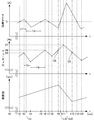
ここで、図8を参照しながら、締結部材として木ネジを用いて制御部77による駆動制御を行った場合の、モータ電流、デューティ比及びブラシレスモータ3(回転軸31)の回転数の時間変化について説明する。図8は、モータ電流、デューティ比及びブラシレスモータ3の回転数の時間変化を示すタイムチャートであり、木ネジに対して締付作業が開始されて回転打撃が行われた後から次の回転打撃が終了するまでの期間を示している。なお、図8における時刻t0は、ブラシレスモータ3が駆動を開始した時刻、時刻t1は、回転打撃が終了し、ライナ部6Aが打撃軸部6Bに対して相対回転し始めた直後の時刻である。
Here, with reference to FIG. 8, changes over time in the motor current, the duty ratio, and the rotation speed of the brushless motor 3 (rotary shaft 31) when drive control is performed by the control unit 77 using wood screws as fastening members. Will be described. FIG. 8 is a time chart showing the time change of the motor current, the duty ratio, and the rotation speed of the brushless motor 3, and the next rotation hit after the tightening operation is started on the wood screw and the rotation hit is performed. Indicates the period until the end of. Note that time t0 in FIG. 8 is the time when the brushless motor 3 starts driving, and time t1 is the time immediately after the rotary hitting is finished and the liner portion 6A starts to rotate relative to the hitting shaft portion 6B. .
最初にモータ電流I及びブラシレスモータ3の回転数(ライナ部6Aの打撃軸部6Bに対する相対回転速度)の時間変化について説明する。
First, time changes of the motor current I and the rotational speed of the brushless motor 3 (relative rotational speed of the liner portion 6A with respect to the striking shaft portion 6B) will be described.
図8に示されているように、モータ電流Iは、回転打撃が終了した後、上述の制御部77による駆動制御により電流閾値I1(目標電流値)を中心として緩やかに上下動しながら推移し、当該モータ電流Iがブラシレスモータ3に流れることにより回転数は上昇していく。時刻t9で次の回転打撃が開始されると回転数が急激に減少するため、モータ電流Iは急激に増加するが、上述の制御部77によるデューティ比減少処理(S102、S105、S106の繰り返し)により、回転打撃中である時刻t12付近でモータ電流Iは減少し始める。モータ電流Iは回転打撃中に徐々に減少し始めるが、回転打撃が終了し回転数が再び上昇を始める時刻t13においてもモータ電流Iは電流閾値I1を超えており、その後も減少し続け、時刻t15付近で再び上昇に転じている。
As shown in FIG. 8, the motor current I changes while gently moving up and down around the current threshold value I1 (target current value) by the drive control by the control unit 77 after the end of the rotation hit. As the motor current I flows through the brushless motor 3, the rotational speed increases. When the next rotation hit is started at time t9, the rotation speed decreases rapidly, so that the motor current I increases rapidly. However, the duty ratio reduction processing (repetition of S102, S105, and S106) by the control unit 77 described above. As a result, the motor current I starts to decrease around time t12 during the rotation hitting. The motor current I starts to gradually decrease during the rotation hit, but the motor current I exceeds the current threshold I1 at time t13 when the rotation hit ends and the rotation speed starts increasing again, and continues to decrease after that. It starts to rise again around t15.
次に、デューティ比の時間変化について、制御部77における処理と併せて説明する。
Next, the time change of the duty ratio will be described together with the processing in the control unit 77.
デューティ比は、回転打撃が終了した後、上述の制御部77よる駆動制御により、増加期間と減少期間とを繰返しながら推移する。言い換えれば、ブラシレスモータ3に印加(供給)される電圧は、回転打撃が終了した後、増加期間と減少期間とを繰返しながら推移する。詳細には、モータ電流Iが電流閾値I1を超えた時刻t1から電流閾値I1以下となる時刻t3まで期間(期間T1)において、制御部77は、上述のデューティ比減少処理を繰り返しており、(S102、S105、S106の繰り返し)、当該処理が遅れて反映され、時刻t2からデューティ比が減少し始め、時刻t4まで減少が継続している(期間T2、減少期間)。
The duty ratio changes while repeating the increase period and the decrease period by the drive control by the above-described control unit 77 after the end of the rotation impact. In other words, the voltage applied (supplied) to the brushless motor 3 changes while repeating the increase period and the decrease period after the end of the rotation impact. Specifically, in a period (period T1) from time t1 when the motor current I exceeds the current threshold I1 to time t3 when the motor current I becomes equal to or less than the current threshold I1, the control unit 77 repeats the above-described duty ratio reduction processing. (Repetition of S102, S105, and S106), the processing is reflected with a delay, the duty ratio starts to decrease from time t2, and continues to decrease until time t4 (period T2, decreasing period).
一方、当該デューティ比減少処理が反映されモータ電流Iが電流閾値I1以下となった時刻t3から電流閾値I1を再び超える時刻t5までの期間(期間T3)において、制御部77は、上述のデューティ比増加処理(S102、S103、S104の繰り返し)を行っており、当該処理が遅れて反映され、時刻t4からデューティ比が増加し始め、時刻t6まで増加が継続している(期間T4、増加期間)。なお、期間T1における制御部77のデューティ比減少処理が遅れて時刻t2から反映され、期間T3における制御部77のデューティ比増加処理が遅れて時刻t4から反映されるのは、制御部77による当該処理からインバータ回路41のFET41A~41Fの駆動までに所定の期間要するからである。
On the other hand, during the period (period T3) from time t3 when the motor current I becomes equal to or lower than the current threshold I1 reflecting the duty ratio reduction process to time t5 when the current exceeds the current threshold I1 again (period T3), the control unit 77 An increase process (repetition of S102, S103, S104) is performed, the process is reflected with a delay, the duty ratio starts increasing from time t4, and continues to increase until time t6 (period T4, increase period) . Note that the duty ratio decreasing process of the control unit 77 in the period T1 is delayed and reflected from the time t2, and the duty ratio increasing process of the control unit 77 in the period T3 is reflected and delayed from the time t4. This is because a predetermined period is required from the processing until the FETs 41A to 41F of the inverter circuit 41 are driven.
このように、上述した制御部77の処理により、デューティ比は増加期間と減少期間とを交互に繰り返しながら推移していき、時刻t9で回転打撃が開始される、すなわち、時刻t9でオイルパルスユニット6で回転打撃力が発生する。回転打撃が開始されるとモータ電流Iが時刻t10で再び電流閾値I1を超え、制御部77は再びデューティ比減少処理を開始し、回転打撃中である時刻t11で遅れて当該処理が反映されデューティ比が減少していく。その後、デューティ比は、回転打撃が終了した時刻t13の後も減少を続け、その後、再び、増加期間となり、上述の過程を繰り返す。なお、打撃開始時(時刻t9)のデューティ比D8は、打撃終了時(時刻t13)のデューティ比D9よりも大きい値となっている。
Thus, by the processing of the control unit 77 described above, the duty ratio changes while alternately repeating the increase period and the decrease period, and the rotational impact is started at time t9, that is, the oil pulse unit at time t9. At 6 a rotational impact force is generated. When the rotation hitting starts, the motor current I exceeds the current threshold value I1 again at time t10, and the control unit 77 starts the duty ratio reduction process again. The ratio is decreasing. Thereafter, the duty ratio continues to decrease after the time t13 when the rotary impact is finished, and then increases again, and the above-described process is repeated. Note that the duty ratio D8 at the start of impact (time t9) is larger than the duty ratio D9 at the end of impact (time t13).
また、制御部77による駆動制御によると、増加期間から減少期間に転じるときのデューティ比の極大値D5、D6、D7は、徐々に上昇していく。すなわち、極大値D7は、極大値D6よりも大きく、極大値D6は極大値D5よりも大きくなる。これは、制御部77によるデューティ比増加処理によってモータ電流Iを増加させた場合のモータ電流Iの上昇率(上昇の傾き)が、デューティ比減少処理によってモータ電流Iを減少させた場合のモータ電流Iの減少率(減少の傾き)よりも小さく、増加期間(例えば、期間T4)が減少期間(例えば、期間T2)よりも長くなるためである。デューティ比増加処理によるモータ電流Iの上昇率がデューティ比減少処理によるモータ電流Iの減少率よりも小さくなる要因は、ブラシレスモータ3の回転数が上昇するにつれてブラシレスモータ3にかかる負荷が小さくなっていき、それによりモータ電流Iが電流閾値I1まで上昇しにくくなるからである。モータ電流Iが電流閾値I1まで上昇するまでにかかる時間が長くなるにつれて、デューティ比が上昇する時間も長くなり、その結果、デューティ比の極大値D5、D6、D7は、徐々に上昇していく。期間T4は、本発明における「増加期間」の一例であり、期間T2は、本発明における「減少期間」の一例である。
Further, according to the drive control by the control unit 77, the maximum values D5, D6, and D7 of the duty ratio when changing from the increase period to the decrease period gradually increase. That is, the maximum value D7 is larger than the maximum value D6, and the maximum value D6 is larger than the maximum value D5. This is because when the motor current I is increased by the duty ratio increasing process by the control unit 77, the motor current I increasing rate (inclination) increases when the motor current I is decreased by the duty ratio decreasing process. This is because the increase rate (for example, the period T4) is smaller than the decrease rate (decrease slope) of I and is longer than the decrease period (for example, the period T2). The reason why the increase rate of the motor current I due to the duty ratio increasing process becomes smaller than the decrease rate of the motor current I due to the duty ratio decreasing process is that the load applied to the brushless motor 3 decreases as the rotation speed of the brushless motor 3 increases. This is because the motor current I is unlikely to rise to the current threshold value I1. As the time taken for the motor current I to rise to the current threshold I1 becomes longer, the time for the duty ratio to rise also becomes longer. As a result, the maximum values D5, D6, and D7 of the duty ratio gradually increase. . The period T4 is an example of the “increase period” in the present invention, and the period T2 is an example of the “decrease period” in the present invention.
本実施の形態においては、制御部77を構成するマイクロコンピュータの処理速度に制限があるため、複数の回転打撃が間欠的に生じる一連の動作において、回転打撃の終了から次の回転打撃の開始までの間に3つのデューティ比の極大値D5、D6、D7が生じるが、制御部77を処理速度のより速いマイクロコンピューターで構成した場合には、デューティ比増加処理とデューティ比減少処理の切り替わりがより頻繁となり、回転打撃の終了から次の回転打撃の開始までの間に生じるデューティ比の極大値の数が増加することになる。
In the present embodiment, since the processing speed of the microcomputer that constitutes the control unit 77 is limited, in a series of operations in which a plurality of rotational impacts are intermittently generated, from the end of the rotational impact to the start of the next rotational impact. Three maximum values D5, D6, and D7 of the duty ratio are generated during the period, but when the control unit 77 is configured with a microcomputer having a higher processing speed, the duty ratio increasing process and the duty ratio decreasing process are more switched. The frequency becomes frequent, and the number of maximum values of the duty ratio that occurs between the end of the rotary hit and the start of the next rotary hit increases.
また本実施の形態においては、S102においてモータ電流Iが電流閾値I1を超えていないと判断した場合には、S104においてデューティ比を指定量(1%)だけ増加させているが、制御部77による定電流制御の追従性の高さがボルト着座の判別ができない程度の高さとならない範囲において、モータ電流Iと電流閾値I1との差が大きくなるほど指定量が大きくなるよう構成してもよい。また、S102においてモータ電流Iが電流閾値I1を超えていると判断し、S105においてモータ電流Iが電流閾値I2を超えていないと判断した場合には、S106においてデューティ比を指定量(1%)だけ減少させているが、制御部77による定電流制御の追従性の高さがボルト着座の判別ができない程度の高さとならない範囲において、モータ電流Iと電流閾値I1との差が大きくなるほど指定量が大きくなるよう構成してもよい。このように構成した場合は、モータ電流Iが電流閾値I1の付近でより細かく上下動することになり、デューティ比増加処理とデューティ比減少処理の切り替わりがより頻繁となる。よってこの場合も、回転打撃の終了から次の回転打撃の開始までの間に生じるデューティ比の極大値の数が増加することになる。
In this embodiment, if it is determined in S102 that the motor current I does not exceed the current threshold value I1, the duty ratio is increased by a specified amount (1%) in S104. In a range where the followability of constant current control is not high enough to prevent bolt seating, the specified amount may be increased as the difference between the motor current I and the current threshold I1 increases. If it is determined in S102 that the motor current I exceeds the current threshold I1, and it is determined in S105 that the motor current I does not exceed the current threshold I2, the duty ratio is set to a specified amount (1%) in S106. However, the specified amount is increased as the difference between the motor current I and the current threshold value I1 is larger in a range where the follow-up performance of the constant current control by the control unit 77 is not so high that the bolt seating cannot be determined. You may comprise so that may become large. In such a configuration, the motor current I moves up and down more finely in the vicinity of the current threshold value I1, and switching between the duty ratio increasing process and the duty ratio decreasing process becomes more frequent. Therefore, also in this case, the number of maximum values of the duty ratio that occurs between the end of the rotation hit and the start of the next rotation hit increases.
以上のようにデューティ比増加処理とデューティ比減少処理の切り替わりがより頻繁となり、回転打撃の終了から次の回転打撃の開始までの間に生じるデューティ比の極大値の数が増加すると、デューティ比の極大値とデューティ比の極小値の差が小さくなるので、回転打撃の終了から次の回転打撃の開始までの間にデューティ比がより滑らかに上昇することになる。このように、デューティ比の時間変化を回転打撃の終了から次の回転打撃の開始までの間で巨視的にみると、デューティ比は全体として徐々に上昇している。デューティ比の極大値と、これに続くデューティ比の極小値との間の平均値を算出し、この平均値が時間の経過とともに上昇していれば、デューティ比は全体として徐々に上昇しているということができる。これによりモータ電流Iが余計に上昇してブラシレスモータ3やFET41A~41Fが発熱するのを抑えながら、ライナ部6Aを所望の回転速度へと加速することができる。なお、本実施の形態においては、極大値D5は例えば90%、極大値D6は例えば95%、極大値D7は100%である。極大値D5の場合のブラシレスモータ3に供給される電圧の値、D6の場合の電圧の値、D7の場合の電圧の値のそれぞれは、本発明における「電圧極大値」の一例である。
As described above, the switching between the duty ratio increasing process and the duty ratio decreasing process becomes more frequent, and when the number of maximum duty ratios that occur between the end of the rotation hit and the start of the next rotation hit increases, Since the difference between the maximum value and the minimum value of the duty ratio becomes small, the duty ratio increases more smoothly between the end of the rotation hit and the start of the next rotation hit. Thus, when the time change of the duty ratio is viewed macroscopically from the end of the rotation hit to the start of the next rotation hit, the duty ratio gradually increases as a whole. The average value between the maximum value of the duty ratio and the subsequent minimum value of the duty ratio is calculated. If this average value increases with time, the duty ratio gradually increases as a whole. It can be said. As a result, it is possible to accelerate the liner portion 6A to a desired rotational speed while suppressing the brushless motor 3 and the FETs 41A to 41F from generating heat due to an excessive increase in the motor current I. In the present embodiment, the maximum value D5 is, for example, 90%, the maximum value D6 is, for example, 95%, and the maximum value D7 is, for example, 100%. Each of the value of the voltage supplied to the brushless motor 3 in the case of the maximum value D5, the value of the voltage in the case of D6, and the value of the voltage in the case of D7 is an example of the “voltage maximum value” in the present invention.
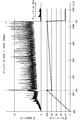
次に、図9を参照しながら、締結部材として木ネジを用いて制御部77による駆動制御を行った場合の回転打撃の周期について説明する。図9は、制御部77による駆動制御を行った場合の回転打撃の周期を説明する図であり、回転打撃5回分の期間におけるモータ電流及び回転数の時間変化を示している。
Next, with reference to FIG. 9, a description will be given of a rotation hitting cycle when drive control is performed by the control unit 77 using wood screws as fastening members. FIG. 9 is a diagram for explaining a rotation hitting cycle when drive control is performed by the control unit 77, and shows a time change of the motor current and the number of rotations in a period corresponding to five rotation hits.
図9に示されているように、時刻t16で1回目の回転打撃が開始され、時刻t17で回転打撃が終了しており、2回目の回転打撃が時刻t18で開始されている。また、時刻t19で3回目の回転打撃、時刻t20で4回目の回転打撃、時刻t21で5回目の回転打撃が開始されている。
As shown in FIG. 9, the first rotary hit is started at time t16, the rotary hit is finished at time t17, and the second rotary hit is started at time t18. Also, a third rotary impact is started at time t19, a fourth rotary impact at time t20, and a fifth rotary impact at time t21.
1回目の回転打撃の開始(時刻t16)から2回目の回転打撃の開始(時刻t18)までの回転打撃間隔(回転打撃周期)は、22msであり、2回目の回転打撃(時刻t18)から3回目の回転打撃(時刻t19)までの回転打撃間隔は、20msである。また、3回目の回転打撃(時刻t19)から4回目の回転打撃(時刻t20)までの回転打撃間隔は、26msであり、4回目の回転打撃(時刻t20)から5回目の回転打撃(時刻t21)までの回転打撃間隔は、21msである。時刻t16、時刻t18、時刻t19、時刻t20、時刻t21のそれぞれの時刻から開始される回転打撃は、本発明における「第1の回転打撃」及び「第2の回転打撃」の一例である。仮に、時刻t19から開始される回転打撃を本発明における「第1の回転打撃」の一例とすると、時刻t20から開始される回転打撃は本発明における「第2の回転打撃」の一例となる。
The rotation hitting interval (rotation hitting cycle) from the start of the first rotary hit (time t16) to the start of the second rotary hit (time t18) is 22 ms, and 3 from the second rotary hit (time t18). The rotation hitting interval until the second rotation hit (time t19) is 20 ms. The rotation hit interval from the third rotation hit (time t19) to the fourth rotation hit (time t20) is 26 ms, and the fifth rotation hit (time t21) from the fourth rotation hit (time t20). ) Is 21 ms. The rotation hits that are started from time t16, time t18, time t19, time t20, and time t21 are examples of the “first rotary hit” and the “second rotary hit” in the present invention. Assuming that the rotational impact starting from time t19 is an example of the “first rotational impact” in the present invention, the rotational impact starting from time t20 is an example of the “second rotational impact” in the present invention.
このように、制御部77による駆動制御を行った場合、回転打撃間隔(回転打撃周期)は一定とならず、まばらになる。これは、制御部77による上述のデューティ比減少処理又はデューティ比増加処理に起因して、回転打撃毎にモータ電流I及び回転数の挙動が僅かに異なり、回転打撃終了後からライナ部6Aが打撃軸部6Bに対して180°相対回転するまでの期間(すなわち、回転打撃間隔)も回転打撃毎に異なるためである。
Thus, when drive control by the control unit 77 is performed, the rotation hitting interval (rotation hitting cycle) is not constant but sparse. This is because the behavior of the motor current I and the number of rotations is slightly different for each rotation hit due to the above-described duty ratio reduction process or duty ratio increase process by the control unit 77, and the liner 6A hits after the end of the rotation hit. This is because the period until the shaft portion 6B rotates relative to the shaft portion 6B (that is, the rotation hitting interval) is different for each rotation hitting.
次に、図10を参照しながら、締結部材としてボルトを用いて制御部77による駆動制御を行った場合のモータ電流及びデューティ比の時間変化について説明する。図10は、モータ電流及びデューティ比の時間変化を示すタイムチャートであり、ボルトに対して締付作業を行った場合を示している。なお、図10における時刻t22は、ブラシレスモータ3が駆動を開始した時刻である。
Next, the time change of the motor current and the duty ratio when the drive control is performed by the control unit 77 using a bolt as a fastening member will be described with reference to FIG. FIG. 10 is a time chart showing changes over time in the motor current and the duty ratio, and shows a case where the tightening operation is performed on the bolt. Note that a time t22 in FIG. 10 is a time when the brushless motor 3 starts driving.
図10に示されているように、時刻t22でブラシレスモータ3の駆動が開始して何度か回転打撃を行い、時刻t23でボルトが被締結材に着座するとメインシャフト64にかかる負荷が非常に大きくなり、モータ電流Iが電流閾値I2を超える。モータ電流Iが電流閾値I2を超えると、制御部77がボルト着座であると判断し(S105:Yes)、S107の処理を行う。これにより、デューティ比は一旦80%まで減少する。
As shown in FIG. 10, when the driving of the brushless motor 3 starts at time t22 and several rotation hits are made, and the bolt is seated on the material to be fastened at time t23, the load on the main shaft 64 is very high. The motor current I exceeds the current threshold value I2. When the motor current I exceeds the current threshold I2, the control unit 77 determines that the bolt is seated (S105: Yes), and performs the process of S107. As a result, the duty ratio is once reduced to 80%.
デューティ比が80%まで減少した後は、制御部77のS108~S109の処理の繰り返しにより、800msの期間をかけてデューティ比が80%から100%まで上昇する。この間、モータ電流Iは徐々に上昇していく。時刻23から800ms経過しデューティ比が100%となった時刻24で、制御部77のS110の処理により、デューティ比は20%まで減少する。デューティ比が20%まで減少すると、モータ電流Iも大幅に減少する。
After the duty ratio decreases to 80%, the duty ratio increases from 80% to 100% over a period of 800 ms by repeating the processing of S108 to S109 of the control unit 77. During this time, the motor current I gradually increases. At time 24 when the duty ratio becomes 100% after 800 ms has elapsed from time 23, the duty ratio is reduced to 20% by the processing of S110 of the control unit 77. When the duty ratio is reduced to 20%, the motor current I is also greatly reduced.
上述したように、本実施の形態によるオイルパルスドライバ1は、ブラシレスモータ3と、ブラシレスモータ3によって駆動されるメインシャフト64と、ブラシレスモータ3から打撃軸部6Bに至る動力伝達経路に設けられるとともにブラシレスモータ3の駆動力をメインシャフト64に伝達する回転打撃が間欠的に生じるよう構成されたオイルパルスユニット6と、ブラシレスモータ3に供給される電圧を切り替えるFET41A~41Fと、FET41A~41Fを制御する制御部77と、を備えており、回転打撃(例えば、時刻t18から開始される回転打撃)が終了してから当該回転打撃に続く次の回転打撃(例えば、時刻t19から開始される回転打撃)が開始するまでの間にブラシレスモータ3に供給される電圧が徐々に上昇し始めるように制御部77が構成されている。すなわち、回転打撃が終了してから当該回転打撃に続く次の回転打撃が開始するまでの間にブラシレスモータ3に供給される電圧が上昇を開始し、その後、当該電圧が徐々に上昇するように制御部77は構成されている。ブラシレスモータ3の動力は、ブラシレスモータ3から順に減速機構5及びオイルパルスユニット6を経て先端ビットへと至る経路によって伝達されており、この経路が、本発明における「動力伝達経路」の一例である。
As described above, the oil pulse driver 1 according to the present embodiment is provided in the brushless motor 3, the main shaft 64 driven by the brushless motor 3, and the power transmission path from the brushless motor 3 to the striking shaft portion 6B. Controls an oil pulse unit 6 configured to intermittently generate a rotational blow that transmits the driving force of the brushless motor 3 to the main shaft 64, FETs 41A to 41F for switching the voltage supplied to the brushless motor 3, and FETs 41A to 41F. And a control unit 77 that performs rotation hitting (for example, rotary hitting started at time t18) and the next rotary hitting (for example, rotary hitting started at time t19) following the rotary hitting. ) Gradually increases until the voltage supplied to the brushless motor 3 increases. Control unit 77 is configured to begin. That is, the voltage supplied to the brushless motor 3 starts to rise between the end of the rotary hit and the start of the next rotary hit following the rotary hit, and then the voltage gradually increases. The control unit 77 is configured. The power of the brushless motor 3 is transmitted in order from the brushless motor 3 through the speed reduction mechanism 5 and the oil pulse unit 6 to the tip bit, and this path is an example of the “power transmission path” in the present invention. .
回転打撃工具において締付性能に影響を与える重要な要因の一つとして、回転打撃が開始される直前におけるライナ部6Aの打撃軸部6Bに対する回転速度が重要であることを発明者らは見出した。このため、第2の回転打撃において十分な締付性能を得るためには、第2の回転打撃が開始される直前までにライナ部6Aの打撃軸部6Bに対する回転速度を所望の回転速度まで加速することができれば十分であって、回転打撃が終了してから即座にデューティ比を最大値まで上昇させる必要はない。上記構成のように、回転打撃が終了してから当該回転打撃に続く次の回転打撃が開始するまでの間にブラシレスモータ3に供給される電圧が徐々に上昇し始めるよう制御部77を構成することにより、電流の余計な上昇を抑えながらライナ部6Aを加速することができ、締付性能の低下を抑えながらブラシレスモータ3又はFET41A~41Fの温度上昇を抑制することができる。
The inventors have found that the rotational speed of the liner portion 6A with respect to the striking shaft portion 6B immediately before the start of the rotational striking is important as one of the important factors affecting the tightening performance in the rotational striking tool. . For this reason, in order to obtain sufficient tightening performance in the second rotational impact, the rotational speed of the liner portion 6A with respect to the impact shaft portion 6B is accelerated to a desired rotational speed immediately before the second rotational impact is started. It is sufficient to be able to do this, and it is not necessary to increase the duty ratio to the maximum value immediately after the end of the rotation hit. As in the above-described configuration, the control unit 77 is configured such that the voltage supplied to the brushless motor 3 starts to gradually increase between the end of the rotary hit and the start of the next rotary hit following the rotary hit. Thus, the liner portion 6A can be accelerated while suppressing an excessive increase in current, and the temperature increase of the brushless motor 3 or the FETs 41A to 41F can be suppressed while suppressing a decrease in fastening performance.
また、本実施の形態においては、回転打撃が開始してから当該回転打撃が終了するまでの間にブラシレスモータ3に供給される電圧を徐々に下降させ始めるように制御部77が構成されている。言い換えれば、回転打撃が開始してから当該回転打撃が終了するまでの間にブラシレスモータ3に供給される電圧が下降を開始し、その後、当該電圧が徐々に下降するように制御部77が構成されている。
Further, in the present embodiment, the control unit 77 is configured so that the voltage supplied to the brushless motor 3 starts to gradually decrease between the start of the rotary hit and the end of the rotary hit. . In other words, the control unit 77 is configured such that the voltage supplied to the brushless motor 3 starts to decrease after the rotation hitting and ends, and thereafter the voltage gradually decreases. Has been.
十分な締付性能を得るためには、回転打撃が開始してから回転打撃が終了するまでの間、限られた期間だけモータが大きなトルクを発生すれば十分であって、モータが継続して大きなトルクを発生し続ける必要はないことを発明者らは見出した。このため、回転打撃が開始してから当該回転打撃が終了するまでの間にブラシレスモータ3に供給される電圧を徐々に下降させ始めるよう制御部77を構成することにより、締付性能の低下を抑えながらブラシレスモータ3又はFET41A~41Fの温度上昇を抑制することができる。
In order to obtain a sufficient tightening performance, it is sufficient that the motor generates a large torque for a limited period from the start of the rotation hit to the end of the rotary hit. The inventors have found that it is not necessary to continue to generate a large torque. For this reason, by configuring the control unit 77 to gradually decrease the voltage supplied to the brushless motor 3 from the start of the rotary impact to the end of the rotary impact, the tightening performance is reduced. While suppressing, the temperature rise of the brushless motor 3 or the FETs 41A to 41F can be suppressed.
また、本実施の形態によるオイルパルスドライバ1は、ブラシレスモータ3と、ブラシレスモータ3によって駆動され回転打撃を間欠的に行うオイルパルスユニット6と、ブラシレスモータ3に供給される電圧を切り替えるFET41A~41Fと、FET41A~41Fを制御する制御部77とを備えており、制御部77は、回転打撃の終了後から当該回転打撃に続く次の回転打撃の開始までの期間、ブラシレスモータ3に供給される電圧(PWM信号のデューティ比)が増加期間と減少期間とを交互に繰り返し且つ増加期間から減少期間に転じるときの値である当該電圧の極大値(デューティ比の極大値)が徐々に上昇する(デューティ比の極大値D5、D6、D7の順で大きくなる)ようにブラシレスモータ3に供給される電圧(デューティ比)を制御している。
The oil pulse driver 1 according to the present embodiment includes a brushless motor 3, an oil pulse unit 6 that is driven by the brushless motor 3 to intermittently perform a rotation hit, and FETs 41A to 41F that switch a voltage supplied to the brushless motor 3. And a control unit 77 that controls the FETs 41A to 41F. The control unit 77 is supplied to the brushless motor 3 during a period from the end of the rotary hit to the start of the next rotary hit following the rotary hit. The maximum value (maximum value of the duty ratio) of the voltage, which is a value when the voltage (duty ratio of the PWM signal) alternately repeats the increase period and the decrease period and changes from the increase period to the decrease period, gradually increases ( The voltage (duplex) supplied to the brushless motor 3 so as to increase in the order of the maximum duty ratio D5, D6, D7). And it controls the duty ratio).
上記構成によると、ブラシレスモータ3に供給される電圧が増加期間と減少期間とを交互に繰り返すため、ブラシレスモータ3を流れるモータ電流も増加と減少とを繰り返す。このため、ブラシレスモータ3に供給される電圧を最大(デューティ比を100%)に固定した状態で常時大きいモータ電流が流れる構成と比較して、ブラシレスモータ3又はFET41A~41Fの温度上昇を抑制することができる。また、ブラシレスモータ3に供給される電圧の極大値が徐々に大きくなるため(デューティ比の極大値D5、D6、D7がその順に徐々に大きくなるため)、十分な電圧(電力)がブラシレスモータ3に供給され、回転打撃の終了後から次の回転打撃の開始前までにブラシレスモータ3の回転数(ライナ部6Aの打撃軸部6Bに対する回転速度)を十分に上昇させることができ、十分な回転打撃力を得ることができる。これらにより、ブラシレスモータ3又はFET41D~41Fの温度上昇を抑制しつつも締付性能の低下を抑制することができる。
According to the above configuration, since the voltage supplied to the brushless motor 3 repeats the increase period and the decrease period alternately, the motor current flowing through the brushless motor 3 also repeats the increase and decrease. For this reason, the temperature increase of the brushless motor 3 or the FETs 41A to 41F is suppressed as compared with a configuration in which a large motor current always flows with the voltage supplied to the brushless motor 3 being fixed at the maximum (duty ratio is 100%). be able to. Further, since the maximum value of the voltage supplied to the brushless motor 3 gradually increases (since the maximum values D5, D6, and D7 of the duty ratio gradually increase in that order), a sufficient voltage (power) is supplied to the brushless motor 3. The rotational speed of the brushless motor 3 (the rotational speed of the liner portion 6A with respect to the striking shaft portion 6B) can be sufficiently increased from the end of the rotational impact to the start of the next rotational impact, so that sufficient rotation A striking force can be obtained. Accordingly, it is possible to suppress a decrease in the tightening performance while suppressing a temperature rise of the brushless motor 3 or the FETs 41D to 41F.
また、オイルパルスドライバ1の制御部77は、モータ電流が目標電流値(電流閾値I1)を超えている場合、デューティ比を徐々に減少させ、モータ電流が目標電流値(電流閾値I1)以下である場合、デューティ比を徐々に増加させている。すなわち、制御部77は、モータ電流を目標電流値に近づけるために、ゲインが高く設定されたPIDフィードバック制御のような追従性の高い定電流制御を行わずに、デューティ比を1ms毎に固定値(1%)増減させる制御を行っている。このため、回転打撃時にモータ電流が急激に上昇した場合、デューティ比を減少させモータ電流を低下させるものの、その低下の程度を小さくできるため、締付性能の低下を抑制することができる。なお、本実施の形態において制御部77は、デューティ比を1ms毎に1%増減させる制御を行っているが、これに限られない。例えば、1ms毎に5%以下の固定値でデューティ比を増減する構成であっても上記効果を得ることができ、好ましくは2%以上3%以下ある。
Further, when the motor current exceeds the target current value (current threshold value I1), the control unit 77 of the oil pulse driver 1 gradually decreases the duty ratio so that the motor current is less than or equal to the target current value (current threshold value I1). In some cases, the duty ratio is gradually increased. That is, in order to make the motor current approach the target current value, the control unit 77 does not perform constant current control with high tracking performance such as PID feedback control with a high gain, and sets the duty ratio to a fixed value every 1 ms. (1%) Control to increase or decrease is performed. For this reason, when the motor current suddenly increases at the time of the rotation impact, the duty ratio is decreased and the motor current is decreased. However, since the degree of the decrease can be reduced, the decrease in the tightening performance can be suppressed. In the present embodiment, the control unit 77 performs control to increase / decrease the duty ratio by 1% every 1 ms, but is not limited thereto. For example, even if the duty ratio is increased or decreased by a fixed value of 5% or less every 1 ms, the above effect can be obtained, and preferably 2% or more and 3% or less.
また、オイルパルスドライバ1におけるオイルパルスユニット6は、被締結材への着座時にブラシレスモータ3にかかる負荷が木ネジ等よりも大きいボルトが着座した場合、デューティ比を80%まで減少させた後、80%から100%まで800msをかけて増加させている。このため、着座後のボルトに対してデューティ比を100%に固定した状態で締付作業を行う構成と比較して、モータ電流を低くすることができ、ブラシレスモータ3又はFET41A~41Fの温度上昇を抑制することができる。また、着座後のボルトに対してデューティ比を80%に固定した状態で締付作業を行う構成と比較して、モータ電流を大きくすることができ、締付性能の低下を抑制することができる。すなわち、締付性能の低下を抑えながらブラシレスモータ3又はFET41A~41Fの温度上昇を抑制することができる。
In addition, the oil pulse unit 6 in the oil pulse driver 1 reduces the duty ratio to 80% when a bolt with a load applied to the brushless motor 3 larger than that of a wood screw or the like is seated on the material to be fastened. It is increased from 80% to 100% over 800 ms. For this reason, the motor current can be lowered and the temperature of the brushless motor 3 or the FETs 41A to 41F can be increased as compared with the configuration in which the tightening operation is performed with the duty ratio fixed to 100% with respect to the bolt after sitting. Can be suppressed. In addition, the motor current can be increased and the deterioration of the tightening performance can be suppressed as compared with the configuration in which the tightening operation is performed with the duty ratio fixed to 80% with respect to the bolt after sitting. . That is, it is possible to suppress the temperature rise of the brushless motor 3 or the FETs 41A to 41F while suppressing a decrease in tightening performance.
また、本実施の形態によるオイルパルスドライバ1の制御部77は、モータ電流が目標電流値(電流閾値I1)よりも大きい電流閾値I2を超えた場合、ボルトが被締結材に着座したと判断している。このように、目標電流値(電流閾値I1)よりも大きい電流閾値I2をボルトの着座を判別するために用いているため、着座時に大きなモータ電流が流れるボルトの着座を判別することができる。また、上述したように、オイルパルスドライバ1における制御部77は、目標電流値を超えている場合にデューティ比を徐々に増加させ、目標電流値以下である場合にデューティ比を徐々に減少させる制御を行っているため、ボルト着座時に急激に上昇するモータ電流に対してデューティ比を減少させすぎない。このため、ボルトの着座に伴うモータ電流の上昇を過度に抑制せず、電流閾値I2を用いて行うボルトの着座判別の精度を向上させることができる。
Further, the control unit 77 of the oil pulse driver 1 according to the present embodiment determines that the bolt is seated on the material to be fastened when the motor current exceeds the current threshold value I2 that is larger than the target current value (current threshold value I1). ing. Thus, since the current threshold value I2 larger than the target current value (current threshold value I1) is used to determine the seating of the bolt, it is possible to determine the seating of the bolt through which a large motor current flows during the seating. Further, as described above, the control unit 77 in the oil pulse driver 1 gradually increases the duty ratio when the target current value is exceeded and gradually decreases the duty ratio when the target current value or less. Therefore, the duty ratio is not excessively decreased with respect to the motor current that rapidly increases when the bolt is seated. For this reason, it is possible to improve the accuracy of the bolt seating determination performed using the current threshold value I2 without excessively suppressing an increase in motor current accompanying the seating of the bolt.
また、本実施の形態によるオイルパルスドライバ1の制御部77は、ボルト着座時から800ms経過後にデューティ比を80%よりも小さい20%まで減少させている。このため、ボルト着座時から800ms経過後に大きなモータ電流が流れることがなく、ブラシレスモータ3又はFET41A~41Fの温度上昇をより抑制することができる。
Further, the control unit 77 of the oil pulse driver 1 according to the present embodiment reduces the duty ratio to 20%, which is smaller than 80%, after 800 ms has elapsed since the bolt is seated. For this reason, a large motor current does not flow after 800 ms has elapsed since the bolt is seated, and the temperature rise of the brushless motor 3 or the FETs 41A to 41F can be further suppressed.
また、本実施の形態によるオイルパルスドライバ1の制御部77は、間欠的に行われる回転打撃の周期が不定となるようにデューティ比を制御している。これにより、回転打撃の周期と回転打撃工具内に使用されている機構等とが共振することがない。これにより、回転打撃工具に発生する振動を低減することができ、操作性を向上させることができる。
In addition, the control unit 77 of the oil pulse driver 1 according to the present embodiment controls the duty ratio so that the period of the rotational impact that is intermittently performed becomes indefinite. Thereby, the period of a rotation impact and the mechanism etc. which are used in the rotation impact tool do not resonate. Thereby, the vibration which generate | occur | produces in a rotary impact tool can be reduced, and operativity can be improved.
本発明による回転打撃工具は、上述した実施の形態に限定されず、特許請求の範囲に記載された発明の要旨の範囲内で種々の変更が可能である。例えば、上記の実施の形態においては、オイルパルスドライバ1を例にとって説明したが、これに限定されず、いわゆるハンマとアンビルで構成される打撃機構部を備えたインパクトドライバやインパクトレンチに適用可能である。
The rotary impact tool according to the present invention is not limited to the above-described embodiments, and various modifications can be made within the scope of the gist of the invention described in the claims. For example, in the above embodiment, the oil pulse driver 1 has been described as an example. However, the present invention is not limited to this, and the present invention can be applied to an impact driver or an impact wrench having a striking mechanism portion composed of a so-called hammer and anvil. is there.
また、本実施の形態においては、ライナ部6Aが打撃軸部6Bに対して1回転する間に2回の回転打撃が生じるように構成したが、これに限られない。例えば、ライナ部6Aが打撃軸部6Bに対して1回転する間に1回の回転打撃が生じる構成としてもよい。この場合、第3シール凸部64D及び第4シール凸部64Eを削除すれば、ライナ部6Aが打撃軸部6Bに対して1回転する間に1回の回転打撃が生じる構成とすることができる。
Moreover, in this Embodiment, although comprised so that the liner part 6A may make two rotation impacts while making one rotation with respect to the impact shaft part 6B, it is not restricted to this. For example, it is good also as a structure where one rotation hit occurs while liner 6A makes one rotation with respect to hitting shaft part 6B. In this case, if the third seal convex portion 64D and the fourth seal convex portion 64E are deleted, it can be configured such that one rotation hit occurs while the liner portion 6A makes one rotation with respect to the hit shaft portion 6B. .
また、本実施の形態によるオイルパルスドライバ1においては、ブラシレスモータ3を採用し、制御部77がパルス幅変調(PWM制御)のデューティ比を制御したが、これに限られない。例えば、パルス幅変調(PWM制御)に替えて、パルス振幅変調(PAM制御)によってブラシレスモータに供給される電圧を切り替える構成であってもよい。ブラシレスモータに替えてブラシを備えたモータを採用してもよいし、電池パックPに替えて交流電源によってモータを駆動してもよい。交流電源によってモータを駆動する場合は、制御部77が導通角を制御する構成であってもよい。
Further, in the oil pulse driver 1 according to the present embodiment, the brushless motor 3 is adopted and the control unit 77 controls the duty ratio of pulse width modulation (PWM control). However, the present invention is not limited to this. For example, instead of pulse width modulation (PWM control), the voltage supplied to the brushless motor may be switched by pulse amplitude modulation (PAM control). Instead of the brushless motor, a motor provided with a brush may be employed, or the battery pack P may be replaced with an AC power source to drive the motor. When the motor is driven by an AC power supply, the control unit 77 may be configured to control the conduction angle.
また、本実施の形態によるオイルパルスドライバ1においては、デューティ比を増加させる場合(S104)の指定量(1%)と低下させる場合(S106)の指定量(1%)とが同じ値であったが、これに限られず、デューティ比を増加させる場合(S104)の指定量と低下させる場合(S106)の指定量とを異なった値としてもよい。
In the oil pulse driver 1 according to the present embodiment, the specified amount (1%) when increasing the duty ratio (S104) and the specified amount (1%) when decreasing (S106) are the same value. However, the present invention is not limited to this, and the specified amount when the duty ratio is increased (S104) may be different from the specified amount when the duty ratio is decreased (S106).