以下、図面を参照して本発明の実施形態について詳細に説明する。一部の図面では図示の明瞭化のために部材の一部の図示を省略している。深部とは、挿入部40の挿入方向において現在位置よりも前方の位置を示す。本実施形態では、挿入部40に対する押し込み操作と引き抜き操作とにおいて、例えば、挿入部40の先端部が管路部301の入口301aから管路部301の内部に挿入されている状態で、操作者は管路部301から外部に露出している挿入部40の任意の位置を把持する。押し込み操作とは、操作者が把持部位から挿入部40に付与した押し込み力によって挿入部40を押し込むことを示す。これにより、挿入部40の先端部は、入口301aの前方に存在する深部に向かって押し込まれ、深部に向かって前進移動する。引き抜き操作とは、操作者が把持部位から挿入部40に付与した引き抜き力によって挿入部40を引き抜くことを示す。これにより挿入部40の先端部は、深部から手前に向かって引き抜かれ、入口301aに向かって後退移動する。
Hereinafter, embodiments of the present invention will be described in detail with reference to the drawings. In some drawings, illustration of a part of members is omitted for clarity of illustration. The deep portion indicates a position ahead of the current position in the insertion direction of the insertion portion 40. In the present embodiment, in the push-in operation and the pull-out operation with respect to the insertion portion 40, for example, in a state where the distal end portion of the insertion portion 40 is inserted from the inlet 301 a of the conduit portion 301 into the conduit portion 301. Holds an arbitrary position of the insertion portion 40 exposed to the outside from the pipe line portion 301. The pushing operation indicates that the insertion unit 40 is pushed by the pushing force applied to the insertion unit 40 by the operator from the gripped part. Thereby, the front-end | tip part of the insertion part 40 is pushed toward the deep part which exists ahead of the inlet 301a, and moves forward toward a deep part. The pulling-out operation refers to pulling out the insertion portion 40 by the pulling force applied to the insertion portion 40 by the operator from the gripped part. As a result, the distal end portion of the insertion portion 40 is pulled out from the deep portion toward the front, and moves backward toward the inlet 301a.
[第1の実施形態]
[構成]
図面を参照して第1の実施形態について説明する。
[可撓管挿入装置(以下、挿入装置10と称する)]
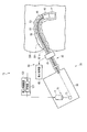
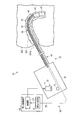
図1に示すような内視鏡装置である挿入装置10は、例えば、手術室または検査室に備えられる。挿入装置10は、医療用の内視鏡20と、内視鏡20に接続される挿入制御装置120とを有する。挿入装置10は、内視鏡20に接続される図示しない光源装置と、内視鏡20に接続される図示しない画像制御装置と、画像制御装置に接続される図示しない表示装置と、画像制御装置に接続される図示しない入力装置とを有する。
[First Embodiment]
[Constitution]
A first embodiment will be described with reference to the drawings.
[Flexible tube insertion device (hereinafter referred to as insertion device 10)]
An insertion apparatus 10 that is an endoscope apparatus as shown in FIG. 1 is provided in an operating room or examination room, for example. The insertion device 10 includes a medical endoscope 20 and an insertion control device 120 connected to the endoscope 20. The insertion device 10 includes a light source device (not shown) connected to the endoscope 20, an image control device (not shown) connected to the endoscope 20, a display device (not shown) connected to the image control device, and an image control device. And an input device not shown.
内視鏡20は、例えば、大腸などの管路部301を有する被挿入体300に挿入される挿入機器の一例である。内視鏡20は、管路部301内を図示しない撮像ユニットの撮像部によって撮像する。
図示しない光源装置は、撮像部が撮像できるよう、光を出射する。光は、内視鏡20の内部に備えられる図示しない照明ユニットの導光部材によって図示しない照明ユニットの照明部まで導光される。光は、照明光として、照明部から外部に向かって出射される。なお撮像部によって撮像された画像は、撮像部から内視鏡20の内部に備えられる撮像ユニットの信号線を介して図示しない画像制御装置に出力される。
図示しない画像制御装置は、撮像部によって撮像された画像が図示しない表示装置に表示されるように、信号処理する。
詳細については後述するが、挿入制御装置120は、内視鏡20に配置される挿入部40の曲げ剛性を制御する。
内視鏡20は、例えば、医療用の軟性内視鏡として説明するが、これに限定される必要はない。内視鏡20は、例えば、工業用の軟性内視鏡、カテーテル、処置具といったように、被挿入体300の内部に挿入される軟性の挿入部40を有していればよい。被挿入体300は、例えば、人に限らず、動物、またはほかの構造物であってもよい。内視鏡20は、直視型の内視鏡20であってもよいし、側視型の内視鏡20であってもよい。
The endoscope 20 is an example of an insertion device that is inserted into an inserted body 300 having a duct portion 301 such as a large intestine. The endoscope 20 images the inside of the conduit section 301 by an imaging unit of an imaging unit (not shown).
A light source device (not shown) emits light so that the imaging unit can capture an image. The light is guided to a lighting unit of a lighting unit (not shown) by a light guide member of a lighting unit (not shown) provided inside the endoscope 20. Light is emitted from the illumination unit to the outside as illumination light. The image picked up by the image pickup unit is output from the image pickup unit to an image control device (not shown) via a signal line of an image pickup unit provided inside the endoscope 20.
An image control device (not shown) performs signal processing so that an image taken by the imaging unit is displayed on a display device (not shown).
Although details will be described later, the insertion control device 120 controls the bending rigidity of the insertion portion 40 disposed in the endoscope 20.
Although the endoscope 20 is described as a medical flexible endoscope, for example, it is not necessary to be limited to this. The endoscope 20 only needs to have a flexible insertion portion 40 that is inserted into the inserted body 300, such as an industrial flexible endoscope, a catheter, or a treatment instrument. The inserted body 300 is not limited to a person, but may be an animal or another structure. The endoscope 20 may be a direct-view type endoscope 20 or a side-view type endoscope 20.
内視鏡20は、操作者によって把持される操作部30と、被挿入体300に挿入される挿入部40とを有する。
操作部30は、挿入部40の基端部に連設される。操作部30は、後述する湾曲部43を操作する図示しない湾曲操作部と、撮像ユニットなど各ユニットを操作する図示しないスイッチ部とを有する。操作部30は、図示しないユニバーサルコードをさらに有しており、ユニバーサルコードを介して図示しない光源装置と図示しない画像制御装置と挿入制御装置120とに接続される。
挿入部40は、管状であり、細長く、柔軟である。挿入部40は、管路部301に対して管路部301の内部を進退移動する。挿入部40は、管路部301の形状に従って湾曲可能である。挿入部40は、挿入部40の先端部から挿入部40の基端部に向かって順に、先端硬質部41と、湾曲部43と、可撓管部45とを有する。先端硬質部41の基端部は湾曲部43の先端部に連結され、湾曲部43の基端部は可撓管部45の先端部に連結され、可撓管部45の基端部は操作部30に連結される。前記した撮像部と照明部とは、先端硬質部41の内部に備えられる。
The endoscope 20 includes an operation unit 30 that is gripped by an operator and an insertion unit 40 that is inserted into the insertion target 300.
The operation unit 30 is connected to the proximal end portion of the insertion unit 40. The operation unit 30 includes a bending operation unit (not shown) that operates a bending unit 43 described later, and a switch unit (not illustrated) that operates each unit such as an imaging unit. The operation unit 30 further includes a universal cord (not shown), and is connected to a light source device (not shown), an image control device (not shown), and an insertion control device 120 via the universal cord.
The insertion portion 40 is tubular, elongated and flexible. The insertion part 40 moves forward and backward in the pipe part 301 with respect to the pipe part 301. The insertion part 40 can be bent according to the shape of the pipe line part 301. The insertion portion 40 has a distal end hard portion 41, a bending portion 43, and a flexible tube portion 45 in order from the distal end portion of the insertion portion 40 toward the proximal end portion of the insertion portion 40. The proximal end portion of the distal end rigid portion 41 is connected to the distal end portion of the bending portion 43, the proximal end portion of the bending portion 43 is connected to the distal end portion of the flexible tube portion 45, and the proximal end portion of the flexible tube portion 45 is operated. It is connected to the part 30. The imaging unit and the illumination unit described above are provided inside the distal end hard portion 41.
図1に示すように、挿入装置10は、挿入部40に配置され、剛性が可変する剛性可変ユニット50を有する。詳細には、剛性可変ユニット50は、挿入部40に内蔵されている。なお剛性可変ユニット50は、少なくとも可撓管部45に内蔵されていればよい。剛性可変ユニット50の先端部は、例えば可撓管部45の先端部に配置される。剛性可変ユニット50の基端部は、例えば操作部30の内部に配置される。
As shown in FIG. 1, the insertion device 10 includes a stiffness variable unit 50 that is disposed in the insertion portion 40 and has a variable stiffness. Specifically, the variable stiffness unit 50 is built in the insertion portion 40. The stiffness variable unit 50 only needs to be built in at least the flexible tube portion 45. The distal end of the variable stiffness unit 50 is disposed at the distal end of the flexible tube 45, for example. For example, the base end portion of the variable stiffness unit 50 is disposed inside the operation unit 30.
剛性可変ユニット50は、例えば、挿入部40に内蔵されるコイル状のシース部材51と、シース部材51の内部を挿通するワイヤ部材53とを有する。シース部材51は、可撓管部45の先端部に配置される先端部と、操作部30の内部に固定される基端部とを有する。シース部材51は、シース部材51の軸方向において伸縮可能である。シース部材51は、例えばシースが縮んだ際に縮む前の初期の長さに戻ろうとする弾性力を有する。シース部材51の基準状態は、伸長している状態である。ワイヤ部材53は、シース部材51の先端部に固定される先端部と、操作部30の内部に配置される基端部とを有する。ワイヤ部材53の基端部は、後述する駆動部70に接続される。
The variable stiffness unit 50 includes, for example, a coiled sheath member 51 built in the insertion portion 40 and a wire member 53 inserted through the inside of the sheath member 51. The sheath member 51 has a distal end portion that is disposed at the distal end portion of the flexible tube portion 45 and a proximal end portion that is fixed inside the operation portion 30. The sheath member 51 can expand and contract in the axial direction of the sheath member 51. The sheath member 51 has an elastic force for returning to the initial length before the sheath member 51 is contracted, for example, when the sheath is contracted. The reference state of the sheath member 51 is an extended state. The wire member 53 has a distal end portion that is fixed to the distal end portion of the sheath member 51 and a proximal end portion that is disposed inside the operation portion 30. The proximal end portion of the wire member 53 is connected to a drive unit 70 described later.
ワイヤ部材53は、駆動部70の牽引によってシース部材51をシース部材51の軸方向に圧縮する。詳細には、ワイヤ部材53は、駆動部70によって挿入部40の基端部に向かって牽引される。ワイヤ部材53は駆動部70の牽引によってシース部材51を挿入部40の基端部に向かって牽引し、シース部材51はワイヤ部材53の牽引によってシース部材51の基端部に向かって圧縮する。したがって、シース部材51の剛性は高まり、シース部材51が配置される部位全体において挿入部40の曲げ剛性は均一に高まり、挿入部40は湾曲状態から略直線状態に変化する。つまり、挿入部40は、略直線化になる。
The wire member 53 compresses the sheath member 51 in the axial direction of the sheath member 51 by pulling the drive unit 70. Specifically, the wire member 53 is pulled toward the proximal end portion of the insertion portion 40 by the driving portion 70. The wire member 53 pulls the sheath member 51 toward the proximal end portion of the insertion portion 40 by pulling the drive unit 70, and the sheath member 51 is compressed toward the proximal end portion of the sheath member 51 by pulling the wire member 53. Therefore, the rigidity of the sheath member 51 is increased, the bending rigidity of the insertion portion 40 is uniformly increased throughout the portion where the sheath member 51 is disposed, and the insertion portion 40 changes from a curved state to a substantially linear state. That is, the insertion part 40 becomes substantially linear.
逆に、ワイヤ部材53の牽引が駆動部70によって解放された際、シース部材51の圧縮が解放される。これによりシース部材51は、シース部材51の弾性力によって元の長さに戻るために伸長する。したがって、シース部材51の剛性は低下し、シース部材51が配置される部位全体において挿入部40の曲げ剛性は均一に低下し、挿入部40の曲げ剛性は初期に戻り、挿入部40は略直線状態から湾曲状態に変化する。つまり、挿入部40は、外力などによって受動的に湾曲しやすい状態となる。外力は、例えば、挿入部40の中心軸に対して任意の角度から挿入部40にかかる力を示す。
Conversely, when the pulling of the wire member 53 is released by the drive unit 70, the compression of the sheath member 51 is released. Thereby, the sheath member 51 is extended to return to the original length by the elastic force of the sheath member 51. Accordingly, the rigidity of the sheath member 51 is reduced, the bending rigidity of the insertion portion 40 is uniformly reduced in the entire portion where the sheath member 51 is disposed, the bending rigidity of the insertion portion 40 returns to the initial state, and the insertion portion 40 is substantially linear. The state changes from the curved state. That is, the insertion portion 40 is easily passively bent by an external force or the like. The external force indicates, for example, a force applied to the insertion portion 40 from an arbitrary angle with respect to the central axis of the insertion portion 40.
このようにシース部材51の剛性はワイヤ部材53の牽引具合によって変化し、シース部材51を内蔵する挿入部40の曲げ剛性はシース部材51の剛性によって変化する。このとき、例えば、剛性可変ユニット50は、挿入部40全体の曲げ剛性を均一に可変(変化)させる。また、剛性可変ユニット50は、シース部材51の剛性によって、挿入部40の曲げ剛性を、挿入部40が略直線化する曲げ剛性に制御する。
As described above, the rigidity of the sheath member 51 changes depending on how the wire member 53 is pulled, and the bending rigidity of the insertion portion 40 including the sheath member 51 changes depending on the rigidity of the sheath member 51. At this time, for example, the variable stiffness unit 50 uniformly varies (changes) the bending stiffness of the entire insertion portion 40. Further, the variable stiffness unit 50 controls the bending rigidity of the insertion portion 40 to the bending rigidity that the insertion portion 40 is substantially linearized by the rigidity of the sheath member 51.
ワイヤ部材53に対する駆動部70の牽引量は、図示しない規制機構によって所望に規制される。規制機構は、例えば、シース部材51とワイヤ部材53と駆動部70とのいずれかに作用する。このため、挿入部40の最も高い曲げ剛性と最も低い曲げ剛性とは、所望に規制される。挿入部40の最も高い曲げ剛性とは、挿入部40が略直線化する曲げ剛性であり、ワイヤ部材53の過度の牽引によって挿入部40が曲がってしまった状態における曲げ剛性を含まない。
The pulling amount of the drive unit 70 with respect to the wire member 53 is regulated as desired by a regulation mechanism (not shown). The restriction mechanism acts on any of the sheath member 51, the wire member 53, and the drive unit 70, for example. For this reason, the highest bending rigidity and the lowest bending rigidity of the insertion part 40 are regulated as desired. The highest bending rigidity of the insertion part 40 is a bending rigidity that makes the insertion part 40 substantially linear, and does not include bending rigidity in a state where the insertion part 40 is bent by excessive pulling of the wire member 53.
図1に示すように、挿入装置10は、挿入部40の進退移動を検出する進退検出ユニット60を有する。進退検出ユニット60は、進退検出ユニット60の検出結果を挿入制御装置120の内部に配置された後述する剛性制御部(以下、制御部121と称する)に出力する。進退検出ユニット60は、被挿入体300の外部に配置されており、挿入部40とは別体である。通常、操作者は、挿入部40を、管路部301の入口301aから管路部301の内部に挿入させ、管路部301から外部に露出している挿入部40の露出部位を把持し、この把持部位から挿入部40を押し込む。露出部位は、例えば挿入部40の基端部である。本実施形態の進退検出ユニット60は、把持部位周辺における挿入部40の前進移動(押し込み操作)と挿入部40の後退移動(引き抜き操作)とを検出する。このため進退検出ユニット60は、被挿入体300の管路部301の外部に露出している挿入部40の露出部位且つ挿入部40の把持部位周辺に配置される。進退検出ユニット60は、例えば、管路部301の入口301a周辺に配置される。挿入部40の前進移動は例えば挿入部40の押し込み操作によって実施され、挿入部40の後退移動は例えば挿入部40の引き抜き操作によって実施される。このため進退検出ユニット60は、入口301a周辺における挿入部40の前進移動(押し込み操作)と挿入部40の後退移動(引き抜き操作)とを検出する。
As shown in FIG. 1, the insertion apparatus 10 includes an advance / retreat detection unit 60 that detects advance / retreat movement of the insertion unit 40. The advance / retreat detection unit 60 outputs the detection result of the advance / retreat detection unit 60 to a stiffness control unit (hereinafter referred to as a control unit 121) described later disposed inside the insertion control device 120. The advance / retreat detection unit 60 is disposed outside the inserted body 300 and is separate from the insertion portion 40. Usually, the operator inserts the insertion portion 40 into the inside of the conduit portion 301 from the inlet 301a of the conduit portion 301, and grips the exposed portion of the insertion portion 40 exposed to the outside from the conduit portion 301. The insertion part 40 is pushed in from this gripping part. The exposed portion is, for example, a proximal end portion of the insertion portion 40. The advance / retreat detection unit 60 of the present embodiment detects the forward movement (pushing operation) of the insertion portion 40 and the backward movement (pulling operation) of the insertion portion 40 in the vicinity of the grasped part. For this reason, the advance / retreat detection unit 60 is disposed around the exposed part of the insertion part 40 exposed to the outside of the pipe line part 301 of the inserted body 300 and the grip part of the insertion part 40. The advance / retreat detection unit 60 is disposed, for example, around the entrance 301a of the pipe section 301. The forward movement of the insertion portion 40 is performed by, for example, a pushing operation of the insertion portion 40, and the backward movement of the insertion portion 40 is performed by, for example, a pulling operation of the insertion portion 40. For this reason, the advance / retreat detection unit 60 detects the forward movement (pushing operation) of the insertion portion 40 and the backward movement (pulling operation) of the insertion portion 40 around the inlet 301a.
進退検出ユニット60は、挿入部40の進退移動に応じて動作する動作部61と、動作部61の動作に応じて、挿入部40の前進移動または挿入部40の後退移動を検出する検出本体部63とを有する。
The advance / retreat detection unit 60 includes an operation unit 61 that operates according to the advance / retreat movement of the insertion unit 40, and a detection main body unit that detects a forward movement of the insertion unit 40 or a backward movement of the insertion unit 40 according to the operation of the operation unit 61. 63.
動作部61は例えばローラ等の回転部材を有し、回転部材は挿入部40の進退移動に応じて回転する。この場合、検出本体部63は、回転部材の回転の向きに応じて挿入部40の前進移動または挿入部40の後退移動を検出する。検出本体部63は、例えばエンコーダを有する。
The operating unit 61 has a rotating member such as a roller, for example, and the rotating member rotates in accordance with the forward / backward movement of the insertion unit 40. In this case, the detection main body 63 detects the forward movement of the insertion portion 40 or the backward movement of the insertion portion 40 according to the direction of rotation of the rotation member. The detection main body 63 has an encoder, for example.
動作部61は、挿入部40の表面の被読取部に向かって光を出射する出射部と、表面の被読取部によって反射される光のパターンを受光する受光部とを有してもよい。出射部は、例えば光源などの発光部である。被読取部は、例えば格子状のパターンなどであり、表面に配置される。被読取部の位置に応じて、反射パターンは、異なる。この場合、検出本体部63は、受光部が受光した光のパターンを基に、挿入部40の前進移動または挿入部40の後退移動を検出する。
The operation unit 61 may include an emitting unit that emits light toward the read unit on the surface of the insertion unit 40 and a light receiving unit that receives the light pattern reflected by the read unit on the surface. The emitting unit is a light emitting unit such as a light source. The read portion is, for example, a lattice pattern, and is arranged on the surface. The reflection pattern varies depending on the position of the read part. In this case, the detection main body 63 detects the forward movement of the insertion section 40 or the backward movement of the insertion section 40 based on the pattern of light received by the light receiving section.
検出本体部63は、図示しない信号線を通じて、検出結果を後述する制御部121に出力する。
The detection main body 63 outputs the detection result to the control unit 121 described later through a signal line (not shown).
図1に示すように、挿入装置10は、挿入制御装置120に配置される制御部121を有する。制御部121は、例えば、ASICなどを含むハードウエア回路によって構成される。制御部121は、プロセッサによって構成されても良い。制御部121がプロセッサで構成される場合、プロセッサがアクセス可能な図示しない内部メモリまたは外部メモリに、プロセッサが実行することで当該プロセッサをこの制御部121として機能させるためのプログラムコードを記憶させておく。
As shown in FIG. 1, the insertion device 10 has a control unit 121 arranged in the insertion control device 120. The control unit 121 is configured by a hardware circuit including, for example, an ASIC. The control unit 121 may be configured by a processor. When the control unit 121 is constituted by a processor, program code for causing the processor to function as the control unit 121 when the processor executes is stored in an internal memory (not shown) or an external memory that is accessible by the processor. .
制御部121は、進退検出ユニット60が挿入部40の前進移動を検出した際に、剛性可変ユニット50の剛性を挿入部40が外力によって受動的に湾曲可能な剛性に制御する。挿入部40が受動的に湾曲可能な剛性とは、挿入部40が管路部301との接触部から受ける抗力によって挿入部40が受動的に湾曲する剛性である。この剛性は、挿入部40が管路部301の形状に沿って湾曲可能となる剛性でもある。例えば、制御部121は、進退検出ユニット60が挿入部40の前進移動を検出した際に、挿入部40が後退移動する際の挿入部40の曲げ剛性に比べて挿入部40が前進移動する際の挿入部40の曲げ剛性が低くなるように剛性可変ユニット50の剛性を低くする。
When the advance / retreat detection unit 60 detects the forward movement of the insertion unit 40, the control unit 121 controls the rigidity of the rigidity variable unit 50 to a rigidity that allows the insertion unit 40 to bend passively by an external force. The rigidity with which the insertion section 40 can bend passively is the rigidity with which the insertion section 40 is passively bent by the drag that the insertion section 40 receives from the contact portion with the pipe line section 301. This rigidity is also a rigidity that allows the insertion portion 40 to bend along the shape of the pipe line portion 301. For example, when the advancement / retraction detection unit 60 detects the forward movement of the insertion part 40, the control unit 121 determines that the insertion part 40 moves forward compared to the bending rigidity of the insertion part 40 when the insertion part 40 moves backward. The rigidity of the variable stiffness unit 50 is lowered so that the bending rigidity of the insertion portion 40 becomes lower.
制御部121は、進退検出ユニット60が挿入部40の後退移動を検出した際に、剛性可変ユニット50の剛性を挿入部40が略直線化する剛性に制御する。例えば制御部121は、進退検出ユニット60が挿入部40の後退移動を検出した際に、挿入部40が前進移動する際の挿入部40の曲げ剛性に比べて挿入部40が後退移動する際の挿入部40の曲げ剛性が高くなるように剛性可変ユニット50の剛性を高くする。具体的には、制御部121は、挿入部40が略直線状態を維持されるように、剛性可変ユニット50の剛性を高める。
When the advance / retreat detection unit 60 detects the backward movement of the insertion part 40, the control part 121 controls the rigidity of the rigidity variable unit 50 to a rigidity that the insertion part 40 substantially linearizes. For example, when the advancement / retraction detection unit 60 detects the backward movement of the insertion part 40, the control unit 121 detects when the insertion part 40 moves backward compared to the bending rigidity of the insertion part 40 when the insertion part 40 moves forward. The rigidity of the variable stiffness unit 50 is increased so that the bending rigidity of the insertion portion 40 is increased. Specifically, the control unit 121 increases the rigidity of the variable stiffness unit 50 so that the insertion unit 40 is maintained in a substantially linear state.
挿入部40が略直線化する剛性とは、屈曲部位203aを含む挿入部40の部位が略直線部位205aに変化し、管路部301との接触部からの抗力などの外力が略直線部位205aに加わっても略直線部位205aが曲がらず略直線状態を維持する剛性をいう。外力は、例えば、略直線部位205aの中心軸に対して任意の角度から略直線部位205aにかかる力を示す。挿入部40が略直線化する剛性は、制御部121によって制御されていない剛性に比べて、高い。また略直線部位205aは、外力を受けても曲がらず略直線状態を維持する高い剛性部位として機能する。剛性が制御されていない他の部位は、外力を受けることによって受動的に曲げられることが可能な低い剛性部位として機能する。なお挿入部40が略直線化する剛性は、管路部301に応じて所望に調整される。
The rigidity at which the insertion portion 40 is substantially straightened means that the portion of the insertion portion 40 including the bent portion 203a is changed to a substantially straight portion 205a, and an external force such as a drag force from a contact portion with the pipe line portion 301 is substantially straight portion 205a. The rigidity that the substantially straight portion 205a does not bend even if it is added to and maintains a substantially straight state. The external force indicates, for example, a force applied to the substantially straight portion 205a from an arbitrary angle with respect to the central axis of the substantially straight portion 205a. The rigidity that the insertion part 40 is substantially linear is higher than the rigidity that is not controlled by the control part 121. The substantially straight portion 205a functions as a highly rigid portion that is not bent even when an external force is applied and maintains a substantially straight state. Other parts whose rigidity is not controlled function as low rigidity parts that can be passively bent by receiving an external force. The rigidity that the insertion portion 40 is substantially straightened is adjusted as desired according to the pipeline portion 301.
制御部121は、図示しない信号線を通じて、剛性可変ユニット50の剛性を制御するための制御信号を後述する駆動部70に出力する。
The control unit 121 outputs a control signal for controlling the rigidity of the variable stiffness unit 50 to the driving unit 70 described later through a signal line (not shown).
図1に示すように、挿入装置10は、制御部121の制御指示を基に剛性可変ユニット50を駆動させる駆動部70を有する。駆動部70は、例えば操作部30に内蔵される。駆動部70は、例えば、制御部121によって制御され、駆動力を発生するモータ71と、駆動力によって回転し、回転によって挿入部40の基端部に向かってワイヤ部材53を牽引するプーリ73とを有する。プーリ73は、駆動力によって、挿入部40の先端部に向かってワイヤ部材53を押圧してもよい。
As shown in FIG. 1, the insertion device 10 includes a drive unit 70 that drives the variable stiffness unit 50 based on a control instruction from the control unit 121. The drive unit 70 is built in the operation unit 30, for example. The drive unit 70 is controlled by the control unit 121, for example, and includes a motor 71 that generates a driving force, a pulley 73 that rotates by the driving force and pulls the wire member 53 toward the proximal end portion of the insertion unit 40 by the rotation. Have The pulley 73 may press the wire member 53 toward the distal end portion of the insertion portion 40 by a driving force.
図示しない入力装置は、挿入制御装置120に接続され、例えば、制御部121の動作を開始させる制御開始指示を制御部121に出力する。入力装置は、一般的な入力用の機器であり、例えば、ボタンスイッチ、ダイヤルである。
An input device (not shown) is connected to the insertion control device 120 and outputs, for example, a control start instruction for starting the operation of the control unit 121 to the control unit 121. The input device is a general input device, for example, a button switch or a dial.
[作用]
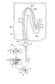
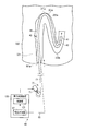
以下、管路部301の一例として、大腸を用いて説明する。例えば操作者は、挿入部40を把持して、挿入部40を大腸の入口301a(肛門)から大腸の内部に挿入させる。次に、操作者は、大腸から外部に露出している挿入部40の基端部を把持し、この把持部位から挿入部40を押し込む。これにより、図2Aと図2Bとに示すように、挿入部40は、入口301aの前方に存在する大腸のS状結腸における第1屈曲部303aに向かって押し込まれ、第1屈曲部303aに向かって前進移動する。
[Action]
Hereinafter, the large intestine will be described as an example of the duct portion 301. For example, the operator holds the insertion portion 40 and inserts the insertion portion 40 into the large intestine from the large intestine entrance 301a (anus). Next, the operator grasps the proximal end portion of the insertion portion 40 exposed to the outside from the large intestine, and pushes the insertion portion 40 from the grasped portion. As a result, as shown in FIGS. 2A and 2B, the insertion portion 40 is pushed toward the first bent portion 303a in the sigmoid colon of the large intestine existing in front of the entrance 301a, and is directed toward the first bent portion 303a. Move forward.
進退検出ユニット60は、挿入部40の前進移動を検出し、検出結果を制御部121に出力する。制御部121は、剛性可変ユニット50の剛性を制御するための制御信号を駆動部70に出力する。駆動部70は、制御部121の制御指示を基に剛性可変ユニット50を駆動させる。この場合、駆動部70は、ワイヤ部材53を挿入部40の先端部に向かって押圧する。シース部材51の圧縮は解放され、シース部材51はシース部材51の弾性力によって伸長する。したがって、シース部材51の剛性は低下し、シース部材51が配置される部位全体において挿入部40の曲げ剛性が均一に低下する。また挿入部40は、受動的に湾曲可能となる。
The advance / retreat detection unit 60 detects the forward movement of the insertion unit 40 and outputs the detection result to the control unit 121. The control unit 121 outputs a control signal for controlling the rigidity of the variable stiffness unit 50 to the drive unit 70. The drive unit 70 drives the variable stiffness unit 50 based on a control instruction from the control unit 121. In this case, the drive unit 70 presses the wire member 53 toward the distal end portion of the insertion unit 40. The compression of the sheath member 51 is released, and the sheath member 51 is extended by the elastic force of the sheath member 51. Therefore, the rigidity of the sheath member 51 is reduced, and the bending rigidity of the insertion portion 40 is uniformly reduced in the entire portion where the sheath member 51 is disposed. Further, the insertion portion 40 can be passively bent.
図2Aでは、挿入部40の曲げ剛性が低くなり、且つ挿入部40が受動的に湾曲可能となっている状態で、挿入部40は第1屈曲部303a(図2Bに示す)に向かって前進移動する。この状態で、図2Bに示すように、挿入部40は、第1屈曲部303aを通過し、第1屈曲部303aの深部に存在する第2屈曲部303bに向かって前進移動し、第2屈曲部303bを通過する。このとき挿入部40は、大腸のS状結腸と下行結腸とをN字型に挿入される。
In FIG. 2A, the insertion portion 40 advances toward the first bent portion 303a (shown in FIG. 2B) in a state where the bending rigidity of the insertion portion 40 is low and the insertion portion 40 is passively bendable. Moving. In this state, as shown in FIG. 2B, the insertion portion 40 passes through the first bent portion 303a, moves forward toward the second bent portion 303b existing deep in the first bent portion 303a, and then enters the second bent portion. It passes through the part 303b. At this time, the insertion section 40 inserts the sigmoid colon and descending colon of the large intestine into an N shape.
図2Aと図2Bとにおいて、剛性可変ユニット50の剛性は挿入部40が受動的に湾曲可能な剛性であり、曲げ剛性が低下した状態で押し込まれる挿入部40は、大腸の内壁から受ける外力によって受動的に湾曲可能である。したがって、挿入部40は、大腸のS状結腸における第1屈曲部303aを第1屈曲部303aに沿って通過可能となる。このため、第1屈曲部303aに対する挿入部40の通過性は向上する。また挿入部40は受動的に湾曲可能で、曲げ剛性が挿入部40全体に渡って均一に低下しており、図2Bに示す第1屈曲部303aを通過している屈曲部位203aの曲げ剛性も挿入部40の他の部位と同様に低下している。このため、挿入部40に対する押し込み操作が過剰に実施されても、第1屈曲部303aは過伸展を抑制され、患者の苦痛は低減される。
2A and 2B, the rigidity of the rigidity variable unit 50 is the rigidity that the insertion part 40 can passively bend, and the insertion part 40 that is pushed in with the bending rigidity lowered is caused by the external force received from the inner wall of the large intestine. It can bend passively. Therefore, the insertion part 40 can pass the 1st bending part 303a in the sigmoid colon of the large intestine along the 1st bending part 303a. For this reason, the passability of the insertion part 40 with respect to the 1st bending part 303a improves. In addition, the insertion portion 40 can bend passively, the bending rigidity is uniformly reduced over the entire insertion portion 40, and the bending rigidity of the bending portion 203a passing through the first bending portion 303a shown in FIG. It has fallen similarly to the other site | part of the insertion part 40. FIG. For this reason, even if pushing operation with respect to the insertion part 40 is implemented excessively, the 1st bending part 303a is suppressed overextension and a patient's pain is reduced.
なお大腸の一部は、腹腔内に固定されていないため、挿入部40の前進移動によって腹腔内を容易に動くことがある。例えば挿入部40の先端部が大腸の第2屈曲部303bを通過した状態で押し込まれると、押し込みによって大腸が動くことがある。すると、挿入部40を押し込む操作者の手元側の力が挿入部40の先端部に伝達され難くなり、挿入部40は座屈してしまう虞がある。このため、挿入部40の先端部には座屈によって手元側の力がますます伝達されにくくなり、先端部は深部に向かって挿入(前進移動)されにくくなる虞がある。このため、挿入部40は推進力が失われるスタック状態となる、言い換えると挿入性が低下する虞がある。挿入部40が容易に挿入されるためには、挿入部40の操作によって大腸を略直線状態に変化させる略直線手技がある。しかしながら、略直線手技の習得は、長い修練が必要である。
In addition, since a part of the large intestine is not fixed in the abdominal cavity, the insertion part 40 may easily move in the abdominal cavity due to the forward movement. For example, when the distal end portion of the insertion portion 40 is pushed in while passing through the second bent portion 303b of the large intestine, the large intestine may move due to the pushing. Then, the force on the operator's hand side that pushes in the insertion portion 40 becomes difficult to be transmitted to the distal end portion of the insertion portion 40, and the insertion portion 40 may be buckled. For this reason, the force on the hand side is less likely to be transmitted to the distal end portion of the insertion portion 40 due to buckling, and the distal end portion may not be easily inserted (moved forward) toward the deep portion. For this reason, the insertion part 40 will be in a stacked state in which the propulsive force is lost. In order to insert the insertion portion 40 easily, there is a substantially straight line technique for changing the large intestine to a substantially straight state by operating the insertion portion 40. However, learning a generally straight line technique requires a long training.
そこで本実施形態では、挿入部40が第2屈曲部303bを通過した後に、引き抜き操作が実施される。図2Cに示すように、挿入部40が引き抜かれた際、進退検出ユニット60は、挿入部40の後退移動を検出し、検出結果を制御部121に出力する。制御部121は、剛性可変ユニット50の剛性を制御するための制御信号を駆動部70に出力する。駆動部70は、制御部121の制御指示を基に剛性可変ユニット50を駆動させる。この場合、駆動部70は、ワイヤ部材53を挿入部40の基端部に向かって牽引する。ワイヤ部材53は駆動部70の牽引によってシース部材51を挿入部40の基端部に向かって牽引し、シース部材51はワイヤ部材の53の牽引によってシース部材51の基端部に向かって圧縮する。したがって、シース部材51の剛性は挿入部40が略直線化する剛性に高まり、シース部材51が配置される部位全体において挿入部40の曲げ剛性が均一に高まる。このとき屈曲部位203aの曲げ剛性も挿入部40の他の部位と同様に高まる。これにより、図2Dと図2Eとに示すように、屈曲部位203aを含む挿入部40の曲率半径は大きくなり、屈曲部位203aを含む挿入部40の部位は湾曲状態から略直線状態に変化する。すなわち、屈曲部位203aを含む挿入部40の部位は、略直線部位205aに変化する。この変化に伴い、第1屈曲部303aと第2屈曲部303bとを含む大腸の部位も、略直線状態に変化する。すなわち、第1屈曲部303aを含む大腸の部位も、略直線部305aに変化する。なお第2屈曲部303bを含む大腸の部位も、同様に、略直線部に変化する。
Therefore, in this embodiment, after the insertion portion 40 passes through the second bent portion 303b, the pulling-out operation is performed. As shown in FIG. 2C, when the insertion unit 40 is pulled out, the advance / retreat detection unit 60 detects the backward movement of the insertion unit 40 and outputs the detection result to the control unit 121. The control unit 121 outputs a control signal for controlling the rigidity of the variable stiffness unit 50 to the drive unit 70. The drive unit 70 drives the variable stiffness unit 50 based on a control instruction from the control unit 121. In this case, the drive unit 70 pulls the wire member 53 toward the proximal end portion of the insertion unit 40. The wire member 53 pulls the sheath member 51 toward the proximal end portion of the insertion portion 40 by pulling the drive unit 70, and the sheath member 51 compresses toward the proximal end portion of the sheath member 51 by pulling the wire member 53. . Therefore, the rigidity of the sheath member 51 is increased to a rigidity at which the insertion portion 40 is substantially linearized, and the bending rigidity of the insertion portion 40 is uniformly increased in the entire portion where the sheath member 51 is disposed. At this time, the bending rigidity of the bending portion 203a is increased similarly to the other portions of the insertion portion 40. As a result, as shown in FIGS. 2D and 2E, the radius of curvature of the insertion portion 40 including the bent portion 203a increases, and the portion of the insertion portion 40 including the bent portion 203a changes from a curved state to a substantially linear state. That is, the part of the insertion portion 40 including the bent part 203a changes to a substantially straight part 205a. With this change, the part of the large intestine including the first bent portion 303a and the second bent portion 303b also changes to a substantially linear state. That is, the large intestine region including the first bent portion 303a also changes to a substantially straight portion 305a. Similarly, the large intestine region including the second bent portion 303b also changes to a substantially straight portion.
図2Eに示すように挿入部40が後退移動を停止した際、制御部121は、進退検出ユニット60から停止の旨を入力され、駆動部70を停止させる制御信号を駆動部70に出力する。駆動部70は、駆動を停止し、ワイヤ部材53の牽引状態を維持する。このため、シース部材51は圧縮を維持し、挿入部40は略直線状態を維持する。
2E, when the insertion unit 40 stops moving backward as shown in FIG. 2E, the control unit 121 receives a stop signal from the advance / retreat detection unit 60 and outputs a control signal for stopping the drive unit 70 to the drive unit 70. The drive unit 70 stops driving and maintains the pulled state of the wire member 53. For this reason, the sheath member 51 maintains compression, and the insertion part 40 maintains a substantially linear state.
略直線状態の挿入部40は、押し込みによって、略直線状態の大腸を深部に向かって容易に挿入されることとなる。挿入部40が再度押し込まれた際、進退検出ユニット60は、挿入部40の前進移動を検出する。そして、制御部121と駆動部70と剛性可変ユニット50とは、上述した動作を繰り返す。
The insertion portion 40 in a substantially straight state can be easily inserted into the deep portion of the large intestine in a substantially straight state by being pushed. When the insertion portion 40 is pushed again, the advance / retreat detection unit 60 detects the forward movement of the insertion portion 40. And the control part 121, the drive part 70, and the rigidity variable unit 50 repeat the operation | movement mentioned above.
挿入部40は略直線状態であり、手元側の力は把持部位から挿入部40の先端部に効率的に伝達される。このため、外力が管路部301から挿入部40に加わっても、高い曲げ剛性を有する略直線部位205aは曲がらず、深部への挿入部40の挿入性は向上する。また座屈の発生は、力の効率的な伝達と、高い曲げ剛性を有する略直線部位205aとによって、抑制される。
The insertion portion 40 is in a substantially straight state, and the force on the hand side is efficiently transmitted from the grasping portion to the distal end portion of the insertion portion 40. For this reason, even if an external force is applied to the insertion part 40 from the pipe line part 301, the substantially linear site | part 205a which has high bending rigidity does not bend, and the insertability of the insertion part 40 to a deep part improves. Further, the occurrence of buckling is suppressed by the efficient transmission of force and the substantially straight portion 205a having high bending rigidity.
[効果]
本実施形態では、進退検出ユニット60が挿入部40の進退移動を検出する。挿入部40が前進移動した際に、制御部121は、剛性可変ユニット50の剛性を挿入部40が受動的に湾曲可能な剛性に制御し、剛性可変ユニット50の剛性を低くする。すると挿入部40が押し込まれた際、挿入部40は、大腸の内壁から受ける外力によって受動的に湾曲でき、大腸のS状結腸における第1屈曲部303aを第1屈曲部303aに沿って通過できる。このため、第1屈曲部303aに対する挿入部40の通過性を向上できる。また挿入部40が後退移動した際に、制御部121は、剛性可変ユニット50の剛性を挿入部40が略直線化する剛性に制御する。すると屈曲部位203aを含む挿入部40の部位は、湾曲状態から略直線状態に変化し、この変化に伴い、第1屈曲部303aと第2屈曲部303bとを含む大腸も略直線状態に変化する。このため、略直線状態の挿入部40の押し込みによって、略直線状態の挿入部40を略直線状態の大腸の深部に向かって容易に挿入でき、管路部301における深部への挿入部40の挿入性を向上できる。このとき、挿入部40は、略直線状態であり、大腸も略直線状態である。したがって挿入部40を押し込む手元側の力は、挿入部40の先端部に伝達され易い。このため、挿入部40の座屈を防止でき、管路部301における深部への挿入部40の挿入性を向上できる。
[effect]
In this embodiment, the advance / retreat detection unit 60 detects the advance / retreat movement of the insertion portion 40. When the insertion unit 40 moves forward, the control unit 121 controls the rigidity of the variable stiffness unit 50 so that the insertion unit 40 can passively bend, thereby reducing the stiffness of the variable stiffness unit 50. Then, when the insertion part 40 is pushed in, the insertion part 40 can passively bend by the external force received from the inner wall of the large intestine, and can pass through the first bent part 303a in the sigmoid colon of the large intestine along the first bent part 303a. . For this reason, the passability of the insertion part 40 with respect to the 1st bending part 303a can be improved. When the insertion unit 40 moves backward, the control unit 121 controls the rigidity of the variable stiffness unit 50 to a rigidity that the insertion unit 40 substantially linearizes. Then, the part of the insertion part 40 including the bent part 203a changes from a curved state to a substantially linear state, and along with this change, the large intestine including the first bent part 303a and the second bent part 303b also changes to a substantially linear state. . For this reason, by pushing the insertion portion 40 in a substantially straight state, the insertion portion 40 in a substantially straight state can be easily inserted toward the deep portion of the large intestine in the substantially straight state, and the insertion portion 40 is inserted into the deep portion in the duct portion 301. Can be improved. At this time, the insertion part 40 is in a substantially straight state, and the large intestine is also in a substantially straight state. Therefore, the hand side force for pushing the insertion portion 40 is easily transmitted to the distal end portion of the insertion portion 40. For this reason, buckling of the insertion part 40 can be prevented and the insertion property of the insertion part 40 to the deep part in the pipe line part 301 can be improved.
本実施形態では、操作者は、挿入部40の曲げ剛性の調整を不要にでき、挿入部40の押し込み操作または引き抜き操作に専念できる。したがって、本実施形態では、管路部301における深部へ挿入部40を挿入する際に、操作性を向上できる。本実施形態では、オーバチューブを用いないため、挿入部40の外径が大きくなることを防止でき、患者の苦痛及び患者への負担を低減できる。
In this embodiment, the operator can make adjustment of the bending rigidity of the insertion portion 40 unnecessary, and can concentrate on the push-in operation or the pull-out operation of the insertion portion 40. Therefore, in this embodiment, when inserting the insertion part 40 in the deep part in the pipe line part 301, operativity can be improved. In this embodiment, since the overtube is not used, it is possible to prevent the outer diameter of the insertion portion 40 from increasing, and to reduce patient pain and burden on the patient.
本実施形態では、修練が必要な略直線手技の習得の難易度を低減でき、略直線手技をサポートできる。
In this embodiment, it is possible to reduce the difficulty of acquiring a substantially straight line technique that requires training, and to support a substantially straight line technique.
本実施形態では、進退検出ユニット60は被挿入体300の外部に配置される。このため、挿入部40の外径が大きくなることを防止でき、管路部301における深部への挿入部40の挿入性をより一層向上できる。進退検出ユニット60は、露出部位且つ把持部位周辺に配置される。このため、手元側における挿入部40の進退移動を確実に検出できる。本実施形態では、動作部61と検出本体部63という簡単な構成で、挿入部40の進退移動を検出できる。
In the present embodiment, the advance / retreat detection unit 60 is disposed outside the inserted body 300. For this reason, it can prevent that the outer diameter of the insertion part 40 becomes large, and the insertability of the insertion part 40 to the deep part in the pipe line part 301 can be improved further. The advance / retreat detection unit 60 is disposed around the exposed part and the grip part. For this reason, the advance / retreat movement of the insertion portion 40 on the hand side can be reliably detected. In the present embodiment, the forward / backward movement of the insertion unit 40 can be detected with a simple configuration of the operation unit 61 and the detection main body unit 63.
本実施形態では、剛性可変ユニット50によって、挿入部40全体の曲げ剛性を均一に変化させる。このため例えば、挿入部40の曲げ剛性を均一に低下でき、挿入部40に対する押し込み操作が過剰に実施されても、第1屈曲部303aの過伸展を抑制でき、患者の苦痛を低減できる。例えば、挿入部40の曲げ剛性を均一に高めることができ、大腸のS状結腸の大部分を略直線状態に変化できる。
In the present embodiment, the bending rigidity of the entire insertion portion 40 is uniformly changed by the rigidity variable unit 50. For this reason, for example, the bending rigidity of the insertion part 40 can be reduced uniformly, and even if the pushing operation to the insertion part 40 is performed excessively, the excessive extension of the first bending part 303a can be suppressed, and the patient's pain can be reduced. For example, the bending rigidity of the insertion part 40 can be increased uniformly, and the majority of the sigmoid colon of the large intestine can be changed to a substantially linear state.
なお進退検出ユニット60は、挿入部40の軸周りにおける回転の向きを検出してもよい。この回転とは、捩じりを表す。捩じりによって回転する回転部材は、回転部材とは別部材である。ここで、挿入部40の基端部から先端部を見た際に、時計回りを右回転、反時計回りを左回転と定義する。制御部121は、例えば、進退検出ユニット60が挿入部40の前進移動と右回転との少なくとも一方を検出した際に、剛性可変ユニット50の剛性を挿入部40が受動的に湾曲可能な剛性に制御する。制御部121は、進退検出ユニット60が挿入部40の後退移動と左回転との少なくとも一方を検出した際に、剛性可変ユニット50の剛性を挿入部40が略直線化する剛性に制御する。これにより本実施形態では、略直線手技をより一層サポートできる。
The advance / retreat detection unit 60 may detect the direction of rotation around the axis of the insertion portion 40. This rotation represents torsion. The rotating member that rotates by twisting is a separate member from the rotating member. Here, when the distal end portion is viewed from the proximal end portion of the insertion portion 40, clockwise rotation is defined as right rotation and counterclockwise rotation is defined as left rotation. For example, when the advance / retreat detection unit 60 detects at least one of forward movement and right rotation of the insertion unit 40, the control unit 121 changes the rigidity of the rigidity variable unit 50 to a rigidity that the insertion unit 40 can passively bend. Control. When the advance / retreat detection unit 60 detects at least one of the backward movement and the left rotation of the insertion unit 40, the control unit 121 controls the rigidity of the stiffness variable unit 50 to a rigidity that the insertion unit 40 substantially linearizes. Thereby, in this embodiment, a substantially straight line procedure can be supported further.
[第1変形例]
図3と図4Aと図4Bと図4Cとを参照して、第1の実施形態の第1変形例について説明する。本変形例では、第1の実施形態とは異なる部分のみ記載する。
[構成]
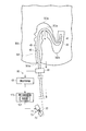
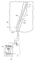
図3に示すように、進退検出ユニット60は、挿入部40の形状を検出する形状検出部65と、挿入部40の押し込み操作または引き抜き操作に対する挿入部40の形状の変化を基に、挿入部40の前進移動または挿入部40の後退移動を検出する検出本体部67とを有する。
[First Modification]
A first modification of the first embodiment will be described with reference to FIGS. 3, 4A, 4B, and 4C. In this modification, only the parts different from the first embodiment will be described.
[Constitution]
As shown in FIG. 3, the advance / retreat detection unit 60 includes a shape detection unit 65 that detects the shape of the insertion unit 40, and an insertion unit based on a change in the shape of the insertion unit 40 with respect to a pushing operation or a drawing operation of the insertion unit 40. 40 and a detection main body 67 for detecting the backward movement of the insertion portion 40.
形状検出部65は、例えば挿入部40に内蔵される。形状検出部65は、剛性可変ユニット50に並んで配置される。形状検出部65は、例えば、コイルと、光ファイバセンサと、加速度センサと、吸収部材との少なくとも1つを有する。コイルは、挿入部40の形状に対応して磁界を発生する。光ファイバセンサにおいて、挿入部40の形状に対応して光の透過率が変化する。吸収部材は、挿入部40の形状に対応してX線を吸収する。
The shape detection unit 65 is built in the insertion unit 40, for example. The shape detection unit 65 is arranged side by side with the variable stiffness unit 50. The shape detection unit 65 includes, for example, at least one of a coil, an optical fiber sensor, an acceleration sensor, and an absorption member. The coil generates a magnetic field corresponding to the shape of the insertion portion 40. In the optical fiber sensor, the light transmittance changes corresponding to the shape of the insertion portion 40. The absorbing member absorbs X-rays corresponding to the shape of the insertion portion 40.
形状検出部65は、入力装置から出力された検出開始指示が形状検出部65に入力された後、常に検出(動作)する。なお検出のタイミングは、一定時間経過毎に実施されていてもよく、特に限定されない。形状検出部65は、例えば有線または無線によって検出本体部67に接続されており、形状検出部65が検出した検出結果を検出本体部67に出力する。
The shape detection unit 65 always detects (operates) after the detection start instruction output from the input device is input to the shape detection unit 65. Note that the detection timing may be performed every time a fixed time elapses, and is not particularly limited. The shape detection unit 65 is connected to the detection main body 67 by, for example, wired or wireless, and outputs the detection result detected by the shape detection unit 65 to the detection main body 67.
検出本体部67は、挿入部40の形状を基に、挿入部40にループ状の屈曲部位203a(図4A参照)が形成されているか否かを、検出する。本変形例における屈曲部位203aとは、例えば、巻回によって1回転されている部位だけでなく、挿入部40が略U字型に曲がっている際に挿入部40のU字状の曲がり部位を含む。一般的に、図4Aに示すように、挿入部40の先端部が第1屈曲部303aを通過した際に、第1屈曲部303aに対する挿入部40の通過部位に、ループ状の屈曲部位203aが発生する。図4Aに示すように、押し込み操作が実施され、屈曲部位203aが第1屈曲部303aの外側内壁311aに当接した状態では、屈曲部位203aの形状は、押し込み操作によって発生し徐々に大きくなる。言い換えると、屈曲部位203aの曲率半径は、押し込み操作によって小さくなる。また図4Bに示すように、引き抜き操作が実施され、屈曲部位203aが第1屈曲部303aの内側内壁311bに当接した状態では、屈曲部位203aの形状は、引き抜き操作によって徐々小さくなり解消する。言い換えると、屈曲部位203aの曲率半径は、引き抜き操作によって大きくなる。このように屈曲部位203aの形状は、押し込み操作または引き抜き操作に応じて変化する。したがって、検出本体部67は、屈曲部位203aの形状の変化を基に、挿入部40の前進移動または挿入部40の後退移動を検出する。
The detection main body 67 detects whether or not the loop-shaped bent portion 203a (see FIG. 4A) is formed in the insertion portion 40 based on the shape of the insertion portion 40. The bent portion 203a in this modification is not only a portion rotated once by winding, for example, but a U-shaped bent portion of the insertion portion 40 when the insertion portion 40 is bent in a substantially U shape. Including. In general, as shown in FIG. 4A, when the distal end portion of the insertion portion 40 passes through the first bending portion 303a, a loop-like bending portion 203a is formed at the passage portion of the insertion portion 40 with respect to the first bending portion 303a. appear. As shown in FIG. 4A, when the pushing operation is performed and the bent portion 203a is in contact with the outer inner wall 311a of the first bent portion 303a, the shape of the bent portion 203a is generated by the pushing operation and gradually increases. In other words, the radius of curvature of the bent portion 203a is reduced by the pushing operation. As shown in FIG. 4B, when the pulling operation is performed and the bent portion 203a is in contact with the inner inner wall 311b of the first bent portion 303a, the shape of the bent portion 203a is gradually reduced and eliminated by the pulling operation. In other words, the radius of curvature of the bent portion 203a is increased by the extraction operation. As described above, the shape of the bent portion 203a changes according to the push-in operation or the pull-out operation. Accordingly, the detection main body 67 detects the forward movement of the insertion portion 40 or the backward movement of the insertion portion 40 based on the change in the shape of the bent portion 203a.
検出本体部67は、屈曲部位203aの形状変化を検出するために、例えば、挿入部40の形状を基に挿入部40における屈曲部位203aの曲率半径を検出する。そして、検出本体部67は、曲率半径が小さくなっていくか大きくなっていくか否かを検出する。
曲率半径が小さくなっていく場合、屈曲部位203aが発生した、押し込み操作が実施された、挿入部40が前進移動している、と検出本体部67は検出する。つまり検出本体部67は、押し込み操作によって挿入部40における屈曲部位203aの形状が大きくなっている際に、挿入部40の前進移動を検出する。
曲率半径が大きくなっていく場合、屈曲部位203aが小さくなり、引き抜き操作が実施された、挿入部40が後退移動している、と検出本体部67は検出する。つまり検出本体部67は、引き抜き操作によって挿入部40における屈曲部位203aの形状が小さくなっている際に、挿入部40の後退移動を検出する。
In order to detect a change in the shape of the bent portion 203a, the detection main body 67 detects, for example, the radius of curvature of the bent portion 203a in the insertion portion 40 based on the shape of the insertion portion 40. And the detection main-body part 67 detects whether a curvature radius becomes small or becomes large.
When the radius of curvature becomes smaller, the detection main body 67 detects that the bending portion 203a has occurred, the push-in operation has been performed, and the insertion portion 40 has moved forward. That is, the detection main body portion 67 detects the forward movement of the insertion portion 40 when the shape of the bent portion 203a in the insertion portion 40 is increased by the pushing operation.
When the radius of curvature is increased, the detection main body 67 detects that the bending portion 203a is reduced, the pulling operation is performed, and the insertion portion 40 is moved backward. That is, the detection main body 67 detects the backward movement of the insertion portion 40 when the shape of the bent portion 203a in the insertion portion 40 is reduced by the pulling-out operation.
検出本体部67は、予め所望に設定された閾値と曲率半径とを比較してもよい。曲率半径が閾値よりも大きい場合、屈曲部位203aが解消された、引き抜き操作が実施された、挿入部40が後退移動している、と検出本体部67は検出する。曲率半径が閾値よりも小さい場合、屈曲部位203aが発生した、押し込み操作が実施された、挿入部40が前進移動している、と検出本体部67は検出する。
The detection main body 67 may compare a predetermined threshold value with a radius of curvature. When the radius of curvature is larger than the threshold value, the detection main body 67 detects that the bending portion 203a has been eliminated, the extraction operation has been performed, and the insertion portion 40 has moved backward. When the radius of curvature is smaller than the threshold value, the detection main body 67 detects that the bending portion 203a has occurred, the pushing operation has been performed, and the insertion portion 40 is moving forward.
本変形例では、進退検出ユニット60は、第1の実施形態とは異なり、第1屈曲部303aに対する挿入部40の通過部位(屈曲部位203a)における挿入部40の前進移動(押し込み操作)と挿入部40の後退移動(引き抜き操作)とを検出する。
In this modified example, the advance / retreat detection unit 60 differs from the first embodiment in that the insertion portion 40 moves forward (push-in operation) and is inserted at the passage portion (bending portion 203a) of the insertion portion 40 with respect to the first bending portion 303a. A backward movement (pulling operation) of the unit 40 is detected.
検出本体部67は、例えば、ASICなどを含むハードウエア回路によって構成される。検出本体部67は、プロセッサによって構成されても良い。検出本体部67がプロセッサで構成される場合、プロセッサがアクセス可能な図示しない内部メモリまたは外部メモリに、プロセッサが実行することで当該プロセッサをこの検出本体部67として機能させるためのプログラムコードを記憶させておく。検出本体部67は、挿入制御装置120に配置される。
The detection main body 67 is configured by a hardware circuit including, for example, an ASIC. The detection main body 67 may be configured by a processor. When the detection main body 67 is constituted by a processor, program code for causing the processor to function as the detection main body 67 by being executed by the processor is stored in an internal memory (not shown) or an external memory that is accessible by the processor. Keep it. The detection main body 67 is disposed in the insertion control device 120.
検出本体部67は、形状検出部65の検出結果が入力された状態で、入力装置から出力された検出開始指示が検出本体部67に入力された後、常に検出(動作)する。なお検出のタイミングは、一定時間経過毎に実施されていてもよく、特に限定されない。検出本体部67は、図示しない信号線を通じて、検出結果を制御部121に出力する。
The detection main body 67 always detects (operates) after the detection start instruction output from the input device is input to the detection main body 67 in a state where the detection result of the shape detection unit 65 is input. Note that the detection timing may be performed every time a fixed time elapses, and is not particularly limited. The detection main body 67 outputs the detection result to the control unit 121 through a signal line (not shown).
[作用]
図4Aに示すように、挿入部40が第1屈曲部303aを通過して深部に挿入される際、第1屈曲部303aを通過する挿入部40の通過部位に、ループ状の屈曲部位203aが発生する。ここで、屈曲部位203aは、押し込み操作によって第1屈曲部303aの外側内壁311aに当接する。すると、屈曲部位203aの曲率半径は、当接によって小さくなっていく。検出本体部67は、形状検出部65を介して、曲率半径が小さくなっていることを検出する。そして、検出本体部67は、挿入部40の前進移動を検出し、検出結果を制御部121に出力する。制御部121は、剛性可変ユニット50の剛性を制御するための制御信号を駆動部70に出力する。駆動部70と剛性可変ユニット50とは、第1の実施形態と同様に駆動する。したがって、シース部材51が配置される部位全体において挿入部40の曲げ剛性が均一に低下する。このとき屈曲部位203aの曲げ剛性も挿入部40の他の部位と同様に低下する。
[Action]
As shown in FIG. 4A, when the insertion portion 40 passes through the first bent portion 303a and is inserted into the deep portion, a loop-like bent portion 203a is formed at the passage portion of the insertion portion 40 that passes through the first bent portion 303a. appear. Here, the bent portion 203a comes into contact with the outer inner wall 311a of the first bent portion 303a by a pushing operation. Then, the curvature radius of the bending part 203a becomes small by contact | abutting. The detection main body 67 detects that the radius of curvature is small via the shape detection unit 65. The detection main body 67 detects the forward movement of the insertion unit 40 and outputs the detection result to the control unit 121. The control unit 121 outputs a control signal for controlling the rigidity of the variable stiffness unit 50 to the drive unit 70. The drive unit 70 and the variable stiffness unit 50 are driven in the same manner as in the first embodiment. Therefore, the bending rigidity of the insertion portion 40 is uniformly reduced in the entire portion where the sheath member 51 is disposed. At this time, the bending rigidity of the bent portion 203a also decreases in the same manner as other portions of the insertion portion 40.
剛性可変ユニット50の剛性は挿入部40が受動的に湾曲可能な剛性であり、曲げ剛性が低下した状態で押し込まれる挿入部40は、大腸の内壁から受ける外力によって受動的に湾曲可能である。したがって、挿入部40は、大腸のS状結腸における第1屈曲部303aを第1屈曲部303aに沿って通過可能となる。このため、第1屈曲部303aに対する挿入部40の通過性は向上する。また挿入部40は受動的に湾曲可能で、曲げ剛性が挿入部40全体に渡って均一に低下しており、第1屈曲部303aを通過している屈曲部位203aの曲げ剛性も挿入部40の他の部位と同様に低下している。このため、挿入部40に対する押し込み操作が過剰に実施されても、第1屈曲部303aは過伸展を抑制され、患者の苦痛は低減される。
The rigidity of the variable stiffness unit 50 is such that the insertion section 40 can bend passively, and the insertion section 40 that is pushed in with the bending rigidity lowered can be passively bent by an external force received from the inner wall of the large intestine. Therefore, the insertion part 40 can pass the 1st bending part 303a in the sigmoid colon of the large intestine along the 1st bending part 303a. For this reason, the passability of the insertion part 40 with respect to the 1st bending part 303a improves. Further, the insertion portion 40 can bend passively, the bending rigidity is uniformly reduced over the entire insertion portion 40, and the bending rigidity of the bending portion 203a passing through the first bending portion 303a is also the same as that of the insertion portion 40. It is lowered as well as other parts. For this reason, even if pushing operation with respect to the insertion part 40 is implemented excessively, the 1st bending part 303a is suppressed overextension and a patient's pain is reduced.
図4Bに示すように、第1屈曲部303aを通過している挿入部40が引き抜かれる際、屈曲部位203aは、引き抜き操作によって第1屈曲部303aの内側内壁311bに当接する。すると、屈曲部位203aの曲率半径は、当接によって大きくなっていく。検出本体部67は、形状検出部65を介して、曲率半径が大きくなっていることを検出する。そして検出本体部67は、挿入部40の後退移動を検出し、検出結果を制御部121に出力する。制御部121は、剛性可変ユニット50の剛性を制御するための制御信号を駆動部70に出力する。駆動部70と剛性可変ユニット50とは、第1の実施形態と同様に駆動する。したがって、シース部材51の剛性は挿入部40が略直線化する剛性に高まり、シース部材51が配置される部位全体において挿入部40の曲げ剛性が均一に高まる。このとき屈曲部位203aの曲げ剛性も挿入部40の他の部位と同様に高まる。これにより、屈曲部位203aを含む挿入部40の曲率半径は大きくなる。そして図4Cと図4Dとに示すように、屈曲部位203aを含む挿入部40の部位は、略直線部位205aに変化する。この変化に従って、第1屈曲部303aと第2屈曲部303bとを含む大腸の部位も、略直線部305aに変化する。
As shown in FIG. 4B, when the insertion portion 40 passing through the first bent portion 303a is pulled out, the bent portion 203a comes into contact with the inner inner wall 311b of the first bent portion 303a by the pulling operation. Then, the curvature radius of the bending part 203a becomes large by contact. The detection main body 67 detects that the radius of curvature is large via the shape detection unit 65. The detection body 67 detects the backward movement of the insertion unit 40 and outputs the detection result to the control unit 121. The control unit 121 outputs a control signal for controlling the rigidity of the variable stiffness unit 50 to the drive unit 70. The drive unit 70 and the variable stiffness unit 50 are driven in the same manner as in the first embodiment. Therefore, the rigidity of the sheath member 51 is increased to a rigidity at which the insertion portion 40 is substantially linearized, and the bending rigidity of the insertion portion 40 is uniformly increased in the entire portion where the sheath member 51 is disposed. At this time, the bending rigidity of the bending portion 203a is increased similarly to the other portions of the insertion portion 40. Thereby, the curvature radius of the insertion part 40 including the bending part 203a becomes large. As shown in FIGS. 4C and 4D, the part of the insertion portion 40 including the bent part 203a changes to a substantially straight part 205a. In accordance with this change, the large intestine region including the first bent portion 303a and the second bent portion 303b also changes to a substantially straight portion 305a.
[効果]
本変形例では、進退検出ユニット60は、第1屈曲部303aに対する挿入部40の通過部位(屈曲部位203a)における挿入部40の前進移動(押し込み操作)と挿入部40の後退移動(引き抜き操作)とを検出する。このため本変形例では、屈曲部位203aにおける挿入部40の進退移動を検出でき、屈曲部位203aの状況に応じて挿入部40全体を受動湾曲可能状態または略直線状態に可変できる。
[effect]
In this modification, the advance / retreat detection unit 60 moves the insertion portion 40 forward (pushing operation) and moves the insertion portion 40 backward (pull-out operation) at the passage portion (bending portion 203a) of the insertion portion 40 with respect to the first bending portion 303a. And detect. For this reason, in this modification, the advancing / retreating movement of the insertion portion 40 in the bending portion 203a can be detected, and the entire insertion portion 40 can be changed to a passively bendable state or a substantially linear state depending on the state of the bending portion 203a.
なお、検出本体部67は、形状検出部65の検出結果を基に、挿入部40の状態情報を算出してもよい。検出本体部67が算出する挿入部40の状態情報は、例えば、挿入部40の形状情報と捩じれ情報と位置情報とを含む。検出本体部67は、表示装置140に接続されており、検出本体部67によって算出された算出結果を表示装置140に出力する。表示装置140は、検出本体部67によって算出された算出結果を基に、管路部301内における現状の挿入部40の状態情報を表示する。管路部301内における現状の挿入部40の状態情報とは、例えば、挿入部40の状態情報が管路部301の状態情報に合わさった情報である。管路部301の状態情報は、例えば、管路部301の形状情報と、管路部301における第1屈曲部303aと第2屈曲部303bとの位置情報とを含む。管路部301の状態情報は、検出本体部67によって、挿入部40の状態情報を基に算出される。表示は、例えば3次元によって実施される。操作者は、表示装置140に表示される挿入部40の状態情報を基に、管路部301内における挿入部40の位置及び状態を監視可能となる。
In addition, the detection main body 67 may calculate the state information of the insertion unit 40 based on the detection result of the shape detection unit 65. The state information of the insertion unit 40 calculated by the detection main body 67 includes, for example, shape information, twist information, and position information of the insertion unit 40. The detection main body 67 is connected to the display device 140, and outputs the calculation result calculated by the detection main body 67 to the display device 140. The display device 140 displays the current state information of the insertion unit 40 in the pipe line part 301 based on the calculation result calculated by the detection main body part 67. The current state information of the insertion unit 40 in the pipe line part 301 is, for example, information in which the state information of the insertion part 40 is matched with the state information of the pipe line part 301. The state information of the pipe line part 301 includes, for example, shape information of the pipe line part 301 and position information of the first bent part 303a and the second bent part 303b in the pipe line part 301. The state information of the pipe line part 301 is calculated by the detection main body part 67 based on the state information of the insertion part 40. The display is performed by, for example, three dimensions. The operator can monitor the position and state of the insertion section 40 in the conduit section 301 based on the state information of the insertion section 40 displayed on the display device 140.
[第2変形例]
図5と図6Aと図6Bと図6Cとを参照して、第1の実施形態の第2変形例について説明する。本変形例では、第1の実施形態の第1変形例とは異なる部分のみ記載する。
[構成]
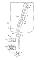
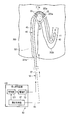
挿入部40の可撓管部45は、挿入部40の軸方向に沿って列状に並ぶ複数のセグメント47に区切られる。セグメント47は、実在しない仮想的な領域として機能してもよいし、実在する構造として機能してもよい。
[Second Modification]
A second modification of the first embodiment will be described with reference to FIGS. 5, 6A, 6B, and 6C. In this modification, only a different part from the 1st modification of 1st Embodiment is described.
[Constitution]
The flexible tube portion 45 of the insertion portion 40 is divided into a plurality of segments 47 arranged in a line along the axial direction of the insertion portion 40. The segment 47 may function as a virtual region that does not exist or may function as a structure that actually exists.
各セグメント47の曲げ剛性は、制御部121の制御によって、独立して変更可能である。可撓管部45の曲げ剛性は、制御部121によって独立して制御される各セグメント47の曲げ剛性によって、部分的に変更可能となる。
なお可撓管部45がセグメント47に区切られるが、これに限定される必要はなく、挿入部40がセグメント47に区切られていてもよい。これにより挿入部40の曲げ剛性は、制御部121によって独立して制御される各セグメント47の曲げ剛性によって、部分的に変更可能となる。
The bending rigidity of each segment 47 can be changed independently under the control of the control unit 121. The bending stiffness of the flexible tube portion 45 can be partially changed by the bending stiffness of each segment 47 that is independently controlled by the control unit 121.
In addition, although the flexible tube part 45 is divided | segmented into the segment 47, it is not necessary to be limited to this, The insertion part 40 may be divided into the segment 47. Thereby, the bending rigidity of the insertion part 40 can be partially changed by the bending rigidity of each segment 47 controlled independently by the control part 121.
本変形例では、剛性可変ユニット50は、剛性が変化する1以上の剛性可変部55を有する。剛性可変部55は、セグメント47毎に内蔵される。剛性可変部55は、全てのセグメント47に内蔵されてもよいし、一部のセグメント47のみに内蔵されてもよい。剛性可変部55が設けられる箇所が、少なくともセグメント47として機能してもよい。なお1つの剛性可変部55が複数のセグメント47に渡って内蔵されてもよい。剛性可変部55は、挿入部40の軸方向に沿って、1列に並んでいてもよいし、複数列に並んでいてもよい。剛性可変部55が複数列に並んでいる場合、剛性可変部55同士は、剛性可変部55同士が可撓管部45の周方向において隣り合うように同じ位置に設けられていてもよいし、挿入部40の軸方向においてずれて設けられていてもよい。剛性可変部55は、剛性可変部55の剛性によって挿入部40の曲げ剛性をセグメント47単位で可変できればよい。
In this modification, the variable stiffness unit 50 includes one or more stiffness variable portions 55 whose stiffness changes. The stiffness variable portion 55 is built in each segment 47. The stiffness variable portion 55 may be built in all the segments 47 or may be built only in some of the segments 47. A portion where the variable stiffness portion 55 is provided may function as at least the segment 47. One rigidity variable portion 55 may be incorporated across the plurality of segments 47. The stiffness variable portions 55 may be arranged in one row along the axial direction of the insertion portion 40 or may be arranged in a plurality of rows. When the stiffness variable portions 55 are arranged in a plurality of rows, the stiffness variable portions 55 may be provided at the same position so that the stiffness variable portions 55 are adjacent to each other in the circumferential direction of the flexible tube portion 45, The insertion portion 40 may be provided so as to be shifted in the axial direction. The stiffness variable portion 55 only needs to be able to vary the bending stiffness of the insertion portion 40 in units of segments 47 by the stiffness of the stiffness variable portion 55.
図示はしないが、剛性可変部55は、例えば、金属線によって形成されるコイルパイプと、コイルパイプの内部に封入された導電性高分子人工筋肉(Electroactive Polymer Artificial Muscle(以下、EPAMと称する)とを有するアクチュエータにより構成される。コイルパイプの中心軸は、挿入部40の中心軸と一致または平行に設けられる。コイルパイプは、コイルパイプの両端部に設けられた電極を有する。
剛性可変部55の電極それぞれは、内視鏡20に内蔵される信号ケーブル57を介して挿入制御装置120に接続され、挿入制御装置120から電力を供給される。電圧が電極を介してEPAMに印加されると、EPAMはコイルパイプの中心軸に沿って伸縮しようとする。しかしながら、EPAMは、コイルパイプによって伸縮を規制される。これにより、剛性可変部55の剛性は変化する。なお剛性可変部55の剛性は、印加される電圧の値が高くなるほど、高まる。剛性可変部55の剛性が変化すると、これに従って剛性可変部55を内蔵するセグメント47の曲げ剛性も変化する。また電力は、電極それぞれに独立して供給される。このため、剛性可変部55それぞれの剛性は独立して変化し、セグメント47それぞれの曲げ剛性も独立して変化する。このように剛性可変部55は、剛性可変部55の剛性の変化によってセグメント47の曲げ剛性を変化させ、セグメント47の曲げ剛性の変化によって可撓管部45の曲げ剛性を部分的に変化させる。
Although not shown, the stiffness variable portion 55 is, for example, a coil pipe formed of a metal wire, and an electroconductive polymer artificial muscle (hereinafter referred to as EPAM) enclosed in the coil pipe. The central axis of the coil pipe is provided so as to coincide with or parallel to the central axis of the insertion portion 40. The coil pipe has electrodes provided at both ends of the coil pipe.
Each of the electrodes of the stiffness varying unit 55 is connected to the insertion control device 120 via a signal cable 57 built in the endoscope 20, and power is supplied from the insertion control device 120. When a voltage is applied to the EPAM through the electrodes, the EPAM tends to expand and contract along the central axis of the coil pipe. However, the expansion and contraction of EPAM is restricted by the coil pipe. As a result, the rigidity of the rigidity variable portion 55 changes. Note that the rigidity of the rigidity variable portion 55 increases as the value of the applied voltage increases. When the stiffness of the stiffness varying portion 55 changes, the bending stiffness of the segment 47 incorporating the stiffness varying portion 55 also changes accordingly. Electric power is supplied to each electrode independently. For this reason, the rigidity of each of the rigidity variable portions 55 changes independently, and the bending rigidity of each of the segments 47 also changes independently. As described above, the stiffness varying unit 55 changes the bending stiffness of the segment 47 by changing the stiffness of the stiffness varying unit 55, and partially changes the bending stiffness of the flexible tube portion 45 by changing the bending stiffness of the segment 47.
剛性可変部55は、EPAMの代わりに、形状記憶合金を用いてもよい。
The rigidity variable portion 55 may use a shape memory alloy instead of EPAM.
本変形例の制御部121は、少なくとも屈曲部位203aに配置されるセグメント47に対応する剛性可変部55の剛性を制御する。そして駆動部70は、少なくとも屈曲部位203aに配置されるセグメント47に対応する剛性可変部55それぞれの剛性を個別に駆動する。駆動部70は、剛性可変部55それぞれに電力を供給する電力供給部である。駆動部70は、挿入制御装置120に配置される電源等である。
The control unit 121 of the present modification controls the rigidity of the rigidity variable unit 55 corresponding to at least the segment 47 arranged in the bent portion 203a. And the drive part 70 drives individually the rigidity of each rigidity variable part 55 corresponding to the segment 47 arrange | positioned at least at the bending | flexion site | part 203a. The drive unit 70 is a power supply unit that supplies power to each of the stiffness variable units 55. The drive unit 70 is a power supply or the like disposed in the insertion control device 120.
[作用]
図6Aに示すように、挿入部40が第1屈曲部303aを通過して深部に挿入される際、第1屈曲部303aを通過する挿入部40の通過部位に、ループ状の屈曲部位203aが発生する。ここで、屈曲部位203aは、押し込み操作によって第1屈曲部303aの外側内壁311aに当接する。すると、屈曲部位203aの曲率半径は、当接によって小さくなっていく。検出本体部67は、形状検出部65を介して、曲率半径が小さくなっていることを検出する。そして、検出本体部67は、挿入部40の前進移動を検出する。また検出本体部67は、検出結果と挿入部40における屈曲部位203aの位置情報とを制御部121に出力する。制御部121は、剛性可変ユニット50の剛性を制御するための制御信号を駆動部70に出力する。駆動部70は、少なくとも屈曲部位203aに配置されるセグメント47に対応する剛性可変部55の剛性が低下するように、剛性可変部55を駆動する。これによって第1屈曲部303aを通過する通過部位である屈曲部位203aの曲げ剛性も低下する。本変形例では、第1の実施形態と第1変形例とのように剛性可変ユニット50が配置される部位全体において挿入部40の曲げ剛性が挿入部40全体に渡って均一に低下するのではない。本変形例では、少なくとも通過部位である屈曲部位203aの曲げ剛性が均一に低下する。
[Action]
As shown in FIG. 6A, when the insertion portion 40 passes through the first bending portion 303a and is inserted into the deep portion, a loop-like bending portion 203a is formed at the passage portion of the insertion portion 40 that passes through the first bending portion 303a. appear. Here, the bent portion 203a comes into contact with the outer inner wall 311a of the first bent portion 303a by a pushing operation. Then, the curvature radius of the bending part 203a becomes small by contact | abutting. The detection main body 67 detects that the radius of curvature is small via the shape detection unit 65. And the detection main-body part 67 detects the advance movement of the insertion part 40. FIG. In addition, the detection main body 67 outputs the detection result and the positional information of the bent part 203 a in the insertion unit 40 to the control unit 121. The control unit 121 outputs a control signal for controlling the rigidity of the variable stiffness unit 50 to the drive unit 70. The drive unit 70 drives the stiffness variable portion 55 so that the stiffness of the stiffness variable portion 55 corresponding to at least the segment 47 disposed in the bent portion 203a is lowered. As a result, the bending rigidity of the bent portion 203a, which is a passing portion that passes through the first bent portion 303a, also decreases. In the present modification, the bending rigidity of the insertion portion 40 does not decrease uniformly over the entire insertion portion 40 in the entire portion where the stiffness variable unit 50 is arranged as in the first embodiment and the first modification. Absent. In this modification, the bending rigidity of at least the bent portion 203a that is a passing portion is uniformly reduced.
このとき屈曲部位203aに位置する剛性可変部55の剛性は屈曲部位203aが受動的に湾曲可能な剛性であり、曲げ剛性が低下した状態で押し込まれる屈曲部位203aは、大腸の内壁から受ける外力によって受動的に湾曲可能である。したがって、屈曲部位203aは、大腸のS状結腸における第1屈曲部303aを第1屈曲部303aに沿って通過可能となる。このため、第1屈曲部303aに対する屈曲部位203aの通過性は向上する。また屈曲部位203aは受動的に湾曲可能で、屈曲部位203aの曲げ剛性が低下している。このため、屈曲部位203aに対する押し込み操作が過剰に実施されても、第1屈曲部303aは過伸展を抑制され、患者の苦痛は低減される。
At this time, the rigidity of the rigidity variable portion 55 located at the bending portion 203a is such that the bending portion 203a can bend passively, and the bending portion 203a that is pushed in with the bending rigidity lowered is caused by an external force received from the inner wall of the large intestine. It can bend passively. Accordingly, the bent portion 203a can pass through the first bent portion 303a in the sigmoid colon of the large intestine along the first bent portion 303a. For this reason, the passability of the bending part 203a with respect to the 1st bending part 303a improves. Further, the bent portion 203a can be bent passively, and the bending rigidity of the bent portion 203a is reduced. For this reason, even if pushing operation with respect to the bending | flexion site | part 203a is implemented excessively, the 1st bending part 303a is suppressed overextension and a patient's pain is reduced.
図6Bに示すように、第1屈曲部303aを通過している挿入部40が引き抜かれる際、屈曲部位203aは、引き抜き操作によって第1屈曲部303aの内側内壁311bに当接する。すると、屈曲部位203aの曲率半径は、当接によって大きくなっていく。検出本体部67は、形状検出部65を介して、曲率半径が大きくなっていることを検出する。そして検出本体部67は、挿入部40の後退移動を検出する。また検出本体部67は、検出結果と、挿入部40における屈曲部位203aの位置情報とを制御部121に出力する。制御部121は、剛性可変ユニット50の剛性を制御するための制御信号を駆動部70に出力する。駆動部70は、少なくとも屈曲部位203aに配置されるセグメント47に対応する剛性可変部55の剛性が高くなるように、剛性可変部55を駆動する。この剛性可変部55を、図6Bと図6Cと図6Dとにおいて、黒塗りで示す。これにより少なくとも屈曲部位203aに位置する剛性可変部55の剛性は高まり、第1屈曲部303aを通過する通過部位である屈曲部位203aの曲げ剛性も高まる。本変形例では、第1の実施形態と第1変形例とのように剛性可変ユニット50が配置される部位全体において挿入部40の曲げ剛性が挿入部40全体に渡って均一に高まるのではない。本変形例では、少なくとも通過部位である屈曲部位203aの曲げ剛性が少なくとも均一に高まる。
As shown in FIG. 6B, when the insertion portion 40 passing through the first bent portion 303a is pulled out, the bent portion 203a comes into contact with the inner inner wall 311b of the first bent portion 303a by the pulling operation. Then, the curvature radius of the bending part 203a becomes large by contact. The detection main body 67 detects that the radius of curvature is large via the shape detection unit 65. The detection main body 67 detects the backward movement of the insertion unit 40. In addition, the detection main body 67 outputs the detection result and the position information of the bent portion 203 a in the insertion unit 40 to the control unit 121. The control unit 121 outputs a control signal for controlling the rigidity of the variable stiffness unit 50 to the drive unit 70. The drive unit 70 drives the variable stiffness portion 55 so that the stiffness of the stiffness variable portion 55 corresponding to at least the segment 47 arranged in the bent portion 203a is increased. The stiffness variable portion 55 is shown in black in FIGS. 6B, 6C, and 6D. As a result, the rigidity of the rigidity variable portion 55 positioned at least at the bending portion 203a is increased, and the bending rigidity of the bending portion 203a, which is a passing portion passing through the first bending portion 303a, is also increased. In the present modification, the bending rigidity of the insertion portion 40 is not uniformly increased over the entire insertion portion 40 in the entire portion where the rigidity variable unit 50 is arranged as in the first embodiment and the first modification. . In this modification, at least the bending rigidity of the bent portion 203a, which is a passage portion, is increased at least uniformly.
このとき、屈曲部位203aに位置する剛性可変部55の剛性は屈曲部位203aが略直線化する剛性に高まり、屈曲部位203aの曲げ剛性が高まる。これにより、屈曲部位203aの曲率半径は大きくなる。そして、図6Cと図6Dとに示すように、屈曲部位203aは略直線部位205aに変化する。この変化に従って、第1屈曲部303aも、略直線部305aに変化する。
At this time, the rigidity of the rigidity variable portion 55 located at the bending part 203a is increased to a rigidity that the bending part 203a is substantially straightened, and the bending rigidity of the bending part 203a is increased. Thereby, the curvature radius of the bending part 203a becomes large. Then, as shown in FIGS. 6C and 6D, the bent portion 203a changes to a substantially straight portion 205a. According to this change, the 1st bending part 303a also changes to the substantially linear part 305a.
挿入部40が後退移動を停止した際、制御部121は、進退検出ユニット60から停止の旨を入力され、駆動部70を停止させる制御信号を駆動部70に出力する。駆動部70は、電力供給を停止し、剛性可変部55の剛性を維持する。このため、挿入部40は、略直線状態を維持する。
When the insertion unit 40 stops moving backward, the control unit 121 receives a stop signal from the advance / retreat detection unit 60 and outputs a control signal for stopping the drive unit 70 to the drive unit 70. The drive unit 70 stops the power supply and maintains the rigidity of the rigidity variable unit 55. For this reason, the insertion part 40 maintains a substantially linear state.
なお、大腸は複数の屈曲部を有している。ここで、挿入部40が複数の屈曲部位を有し、屈曲部位それぞれは屈曲部それぞれに配置されているとする。本変形例では、屈曲部位それぞれに配置される剛性可変部55それぞれの剛性は、同時に可変してもよいし、所望するパターンに応じて可変してもよい。剛性可変部55それぞれの剛性は、全て可変する必要はなく、例えば入力装置の入力指示に応じた箇所のみ可変してもよい。
Note that the large intestine has a plurality of bent portions. Here, it is assumed that the insertion portion 40 has a plurality of bent portions, and each bent portion is disposed in each bent portion. In the present modification, the rigidity of each of the rigidity variable portions 55 arranged at each of the bent portions may be changed at the same time, or may be changed according to a desired pattern. The rigidity of each of the rigidity variable portions 55 does not have to be changed. For example, only the portion corresponding to the input instruction of the input device may be changed.
[効果]
本変形例では、少なくとも屈曲部位203aの状況に応じて、少なくとも屈曲部位203aを受動湾曲可能状態または略直線状態に可変できる。
[effect]
In this modification, at least the bending portion 203a can be changed to a passively bendable state or a substantially linear state according to at least the state of the bending portion 203a.
本変形例では、制御部121は、屈曲部位203aに配置されるセグメント47に対応する剛性可変部55の剛性を制御する。このため、挿入部40の曲げ剛性を精緻に制御できる。
In the present modification, the control unit 121 controls the stiffness of the stiffness varying unit 55 corresponding to the segment 47 arranged in the bent portion 203a. For this reason, the bending rigidity of the insertion portion 40 can be precisely controlled.
本発明は、上記実施形態そのままに限定されるものではなく、実施段階ではその要旨を逸脱しない範囲で構成要素を変形して具体化できる。また、上記実施形態に開示される複数の構成要素の適宜な組み合せにより種々の発明を形成できる。
The present invention is not limited to the above-described embodiment as it is, and can be embodied by modifying the constituent elements without departing from the scope of the invention in the implementation stage. Moreover, various inventions can be formed by appropriately combining a plurality of constituent elements disclosed in the embodiment.