WO2017109966A1 - Three-dimensional additive manufacturing device, control method of three-dimensional additive manufacturing device, and control program of three-dimensional additive manufacturing device - Google Patents
Three-dimensional additive manufacturing device, control method of three-dimensional additive manufacturing device, and control program of three-dimensional additive manufacturing device Download PDFInfo
- Publication number
- WO2017109966A1 WO2017109966A1 PCT/JP2015/086306 JP2015086306W WO2017109966A1 WO 2017109966 A1 WO2017109966 A1 WO 2017109966A1 JP 2015086306 W JP2015086306 W JP 2015086306W WO 2017109966 A1 WO2017109966 A1 WO 2017109966A1
- Authority
- WO
- WIPO (PCT)
- Prior art keywords
- additive manufacturing
- manufacturing apparatus
- dimensional
- dimensional additive
- cartridge
- Prior art date
Links
Images


Classifications
-
- B—PERFORMING OPERATIONS; TRANSPORTING
- B29—WORKING OF PLASTICS; WORKING OF SUBSTANCES IN A PLASTIC STATE IN GENERAL
- B29C—SHAPING OR JOINING OF PLASTICS; SHAPING OF MATERIAL IN A PLASTIC STATE, NOT OTHERWISE PROVIDED FOR; AFTER-TREATMENT OF THE SHAPED PRODUCTS, e.g. REPAIRING
- B29C64/00—Additive manufacturing, i.e. manufacturing of three-dimensional [3D] objects by additive deposition, additive agglomeration or additive layering, e.g. by 3D printing, stereolithography or selective laser sintering
- B29C64/10—Processes of additive manufacturing
- B29C64/141—Processes of additive manufacturing using only solid materials
- B29C64/147—Processes of additive manufacturing using only solid materials using sheet material, e.g. laminated object manufacturing [LOM] or laminating sheet material precut to local cross sections of the 3D object
-
- B—PERFORMING OPERATIONS; TRANSPORTING
- B22—CASTING; POWDER METALLURGY
- B22F—WORKING METALLIC POWDER; MANUFACTURE OF ARTICLES FROM METALLIC POWDER; MAKING METALLIC POWDER; APPARATUS OR DEVICES SPECIALLY ADAPTED FOR METALLIC POWDER
- B22F10/00—Additive manufacturing of workpieces or articles from metallic powder
- B22F10/20—Direct sintering or melting
- B22F10/28—Powder bed fusion, e.g. selective laser melting [SLM] or electron beam melting [EBM]
-
- B—PERFORMING OPERATIONS; TRANSPORTING
- B22—CASTING; POWDER METALLURGY
- B22F—WORKING METALLIC POWDER; MANUFACTURE OF ARTICLES FROM METALLIC POWDER; MAKING METALLIC POWDER; APPARATUS OR DEVICES SPECIALLY ADAPTED FOR METALLIC POWDER
- B22F10/00—Additive manufacturing of workpieces or articles from metallic powder
- B22F10/30—Process control
- B22F10/32—Process control of the atmosphere, e.g. composition or pressure in a building chamber
-
- B—PERFORMING OPERATIONS; TRANSPORTING
- B29—WORKING OF PLASTICS; WORKING OF SUBSTANCES IN A PLASTIC STATE IN GENERAL
- B29C—SHAPING OR JOINING OF PLASTICS; SHAPING OF MATERIAL IN A PLASTIC STATE, NOT OTHERWISE PROVIDED FOR; AFTER-TREATMENT OF THE SHAPED PRODUCTS, e.g. REPAIRING
- B29C64/00—Additive manufacturing, i.e. manufacturing of three-dimensional [3D] objects by additive deposition, additive agglomeration or additive layering, e.g. by 3D printing, stereolithography or selective laser sintering
- B29C64/10—Processes of additive manufacturing
- B29C64/141—Processes of additive manufacturing using only solid materials
- B29C64/153—Processes of additive manufacturing using only solid materials using layers of powder being selectively joined, e.g. by selective laser sintering or melting
-
- B—PERFORMING OPERATIONS; TRANSPORTING
- B29—WORKING OF PLASTICS; WORKING OF SUBSTANCES IN A PLASTIC STATE IN GENERAL
- B29C—SHAPING OR JOINING OF PLASTICS; SHAPING OF MATERIAL IN A PLASTIC STATE, NOT OTHERWISE PROVIDED FOR; AFTER-TREATMENT OF THE SHAPED PRODUCTS, e.g. REPAIRING
- B29C64/00—Additive manufacturing, i.e. manufacturing of three-dimensional [3D] objects by additive deposition, additive agglomeration or additive layering, e.g. by 3D printing, stereolithography or selective laser sintering
- B29C64/20—Apparatus for additive manufacturing; Details thereof or accessories therefor
- B29C64/205—Means for applying layers
- B29C64/214—Doctor blades
-
- B—PERFORMING OPERATIONS; TRANSPORTING
- B29—WORKING OF PLASTICS; WORKING OF SUBSTANCES IN A PLASTIC STATE IN GENERAL
- B29C—SHAPING OR JOINING OF PLASTICS; SHAPING OF MATERIAL IN A PLASTIC STATE, NOT OTHERWISE PROVIDED FOR; AFTER-TREATMENT OF THE SHAPED PRODUCTS, e.g. REPAIRING
- B29C64/00—Additive manufacturing, i.e. manufacturing of three-dimensional [3D] objects by additive deposition, additive agglomeration or additive layering, e.g. by 3D printing, stereolithography or selective laser sintering
- B29C64/30—Auxiliary operations or equipment
- B29C64/307—Handling of material to be used in additive manufacturing
- B29C64/321—Feeding
- B29C64/336—Feeding of two or more materials
-
- B—PERFORMING OPERATIONS; TRANSPORTING
- B29—WORKING OF PLASTICS; WORKING OF SUBSTANCES IN A PLASTIC STATE IN GENERAL
- B29C—SHAPING OR JOINING OF PLASTICS; SHAPING OF MATERIAL IN A PLASTIC STATE, NOT OTHERWISE PROVIDED FOR; AFTER-TREATMENT OF THE SHAPED PRODUCTS, e.g. REPAIRING
- B29C64/00—Additive manufacturing, i.e. manufacturing of three-dimensional [3D] objects by additive deposition, additive agglomeration or additive layering, e.g. by 3D printing, stereolithography or selective laser sintering
- B29C64/30—Auxiliary operations or equipment
- B29C64/386—Data acquisition or data processing for additive manufacturing
- B29C64/393—Data acquisition or data processing for additive manufacturing for controlling or regulating additive manufacturing processes
-
- B—PERFORMING OPERATIONS; TRANSPORTING
- B33—ADDITIVE MANUFACTURING TECHNOLOGY
- B33Y—ADDITIVE MANUFACTURING, i.e. MANUFACTURING OF THREE-DIMENSIONAL [3-D] OBJECTS BY ADDITIVE DEPOSITION, ADDITIVE AGGLOMERATION OR ADDITIVE LAYERING, e.g. BY 3-D PRINTING, STEREOLITHOGRAPHY OR SELECTIVE LASER SINTERING
- B33Y10/00—Processes of additive manufacturing
-
- B—PERFORMING OPERATIONS; TRANSPORTING
- B33—ADDITIVE MANUFACTURING TECHNOLOGY
- B33Y—ADDITIVE MANUFACTURING, i.e. MANUFACTURING OF THREE-DIMENSIONAL [3-D] OBJECTS BY ADDITIVE DEPOSITION, ADDITIVE AGGLOMERATION OR ADDITIVE LAYERING, e.g. BY 3-D PRINTING, STEREOLITHOGRAPHY OR SELECTIVE LASER SINTERING
- B33Y30/00—Apparatus for additive manufacturing; Details thereof or accessories therefor
-
- B—PERFORMING OPERATIONS; TRANSPORTING
- B33—ADDITIVE MANUFACTURING TECHNOLOGY
- B33Y—ADDITIVE MANUFACTURING, i.e. MANUFACTURING OF THREE-DIMENSIONAL [3-D] OBJECTS BY ADDITIVE DEPOSITION, ADDITIVE AGGLOMERATION OR ADDITIVE LAYERING, e.g. BY 3-D PRINTING, STEREOLITHOGRAPHY OR SELECTIVE LASER SINTERING
- B33Y50/00—Data acquisition or data processing for additive manufacturing
- B33Y50/02—Data acquisition or data processing for additive manufacturing for controlling or regulating additive manufacturing processes
-
- B—PERFORMING OPERATIONS; TRANSPORTING
- B08—CLEANING
- B08B—CLEANING IN GENERAL; PREVENTION OF FOULING IN GENERAL
- B08B15/00—Preventing escape of dirt or fumes from the area where they are produced; Collecting or removing dirt or fumes from that area
- B08B15/02—Preventing escape of dirt or fumes from the area where they are produced; Collecting or removing dirt or fumes from that area using chambers or hoods covering the area
-
- B—PERFORMING OPERATIONS; TRANSPORTING
- B22—CASTING; POWDER METALLURGY
- B22F—WORKING METALLIC POWDER; MANUFACTURE OF ARTICLES FROM METALLIC POWDER; MAKING METALLIC POWDER; APPARATUS OR DEVICES SPECIALLY ADAPTED FOR METALLIC POWDER
- B22F10/00—Additive manufacturing of workpieces or articles from metallic powder
- B22F10/30—Process control
- B22F10/32—Process control of the atmosphere, e.g. composition or pressure in a building chamber
- B22F10/322—Process control of the atmosphere, e.g. composition or pressure in a building chamber of the gas flow, e.g. rate or direction
-
- B—PERFORMING OPERATIONS; TRANSPORTING
- B22—CASTING; POWDER METALLURGY
- B22F—WORKING METALLIC POWDER; MANUFACTURE OF ARTICLES FROM METALLIC POWDER; MAKING METALLIC POWDER; APPARATUS OR DEVICES SPECIALLY ADAPTED FOR METALLIC POWDER
- B22F12/00—Apparatus or devices specially adapted for additive manufacturing; Auxiliary means for additive manufacturing; Combinations of additive manufacturing apparatus or devices with other processing apparatus or devices
- B22F12/40—Radiation means
- B22F12/41—Radiation means characterised by the type, e.g. laser or electron beam
- B22F12/43—Radiation means characterised by the type, e.g. laser or electron beam pulsed; frequency modulated
-
- B—PERFORMING OPERATIONS; TRANSPORTING
- B22—CASTING; POWDER METALLURGY
- B22F—WORKING METALLIC POWDER; MANUFACTURE OF ARTICLES FROM METALLIC POWDER; MAKING METALLIC POWDER; APPARATUS OR DEVICES SPECIALLY ADAPTED FOR METALLIC POWDER
- B22F12/00—Apparatus or devices specially adapted for additive manufacturing; Auxiliary means for additive manufacturing; Combinations of additive manufacturing apparatus or devices with other processing apparatus or devices
- B22F12/70—Gas flow means
-
- B—PERFORMING OPERATIONS; TRANSPORTING
- B22—CASTING; POWDER METALLURGY
- B22F—WORKING METALLIC POWDER; MANUFACTURE OF ARTICLES FROM METALLIC POWDER; MAKING METALLIC POWDER; APPARATUS OR DEVICES SPECIALLY ADAPTED FOR METALLIC POWDER
- B22F7/00—Manufacture of composite layers, workpieces, or articles, comprising metallic powder, by sintering the powder, with or without compacting wherein at least one part is obtained by sintering or compression
- B22F7/06—Manufacture of composite layers, workpieces, or articles, comprising metallic powder, by sintering the powder, with or without compacting wherein at least one part is obtained by sintering or compression of composite workpieces or articles from parts, e.g. to form tipped tools
-
- B—PERFORMING OPERATIONS; TRANSPORTING
- B29—WORKING OF PLASTICS; WORKING OF SUBSTANCES IN A PLASTIC STATE IN GENERAL
- B29C—SHAPING OR JOINING OF PLASTICS; SHAPING OF MATERIAL IN A PLASTIC STATE, NOT OTHERWISE PROVIDED FOR; AFTER-TREATMENT OF THE SHAPED PRODUCTS, e.g. REPAIRING
- B29C64/00—Additive manufacturing, i.e. manufacturing of three-dimensional [3D] objects by additive deposition, additive agglomeration or additive layering, e.g. by 3D printing, stereolithography or selective laser sintering
- B29C64/20—Apparatus for additive manufacturing; Details thereof or accessories therefor
- B29C64/205—Means for applying layers
- B29C64/209—Heads; Nozzles
-
- B—PERFORMING OPERATIONS; TRANSPORTING
- B29—WORKING OF PLASTICS; WORKING OF SUBSTANCES IN A PLASTIC STATE IN GENERAL
- B29C—SHAPING OR JOINING OF PLASTICS; SHAPING OF MATERIAL IN A PLASTIC STATE, NOT OTHERWISE PROVIDED FOR; AFTER-TREATMENT OF THE SHAPED PRODUCTS, e.g. REPAIRING
- B29C64/00—Additive manufacturing, i.e. manufacturing of three-dimensional [3D] objects by additive deposition, additive agglomeration or additive layering, e.g. by 3D printing, stereolithography or selective laser sintering
- B29C64/40—Structures for supporting 3D objects during manufacture and intended to be sacrificed after completion thereof
-
- B—PERFORMING OPERATIONS; TRANSPORTING
- B33—ADDITIVE MANUFACTURING TECHNOLOGY
- B33Y—ADDITIVE MANUFACTURING, i.e. MANUFACTURING OF THREE-DIMENSIONAL [3-D] OBJECTS BY ADDITIVE DEPOSITION, ADDITIVE AGGLOMERATION OR ADDITIVE LAYERING, e.g. BY 3-D PRINTING, STEREOLITHOGRAPHY OR SELECTIVE LASER SINTERING
- B33Y50/00—Data acquisition or data processing for additive manufacturing
-
- G—PHYSICS
- G05—CONTROLLING; REGULATING
- G05B—CONTROL OR REGULATING SYSTEMS IN GENERAL; FUNCTIONAL ELEMENTS OF SUCH SYSTEMS; MONITORING OR TESTING ARRANGEMENTS FOR SUCH SYSTEMS OR ELEMENTS
- G05B19/00—Programme-control systems
-
- G—PHYSICS
- G05—CONTROLLING; REGULATING
- G05B—CONTROL OR REGULATING SYSTEMS IN GENERAL; FUNCTIONAL ELEMENTS OF SUCH SYSTEMS; MONITORING OR TESTING ARRANGEMENTS FOR SUCH SYSTEMS OR ELEMENTS
- G05B19/00—Programme-control systems
- G05B19/02—Programme-control systems electric
- G05B19/04—Programme control other than numerical control, i.e. in sequence controllers or logic controllers
- G05B19/05—Programmable logic controllers, e.g. simulating logic interconnections of signals according to ladder diagrams or function charts
- G05B19/056—Programming the PLC
-
- Y—GENERAL TAGGING OF NEW TECHNOLOGICAL DEVELOPMENTS; GENERAL TAGGING OF CROSS-SECTIONAL TECHNOLOGIES SPANNING OVER SEVERAL SECTIONS OF THE IPC; TECHNICAL SUBJECTS COVERED BY FORMER USPC CROSS-REFERENCE ART COLLECTIONS [XRACs] AND DIGESTS
- Y02—TECHNOLOGIES OR APPLICATIONS FOR MITIGATION OR ADAPTATION AGAINST CLIMATE CHANGE
- Y02P—CLIMATE CHANGE MITIGATION TECHNOLOGIES IN THE PRODUCTION OR PROCESSING OF GOODS
- Y02P10/00—Technologies related to metal processing
- Y02P10/25—Process efficiency
Definitions
- the present invention relates to a control method for a three-dimensional additive manufacturing apparatus, a control method for the three-dimensional additive manufacturing apparatus, and a control program for the three-dimensional additive manufacturing apparatus.
- Patent Document 1 discloses a technique for storing in advance a powder supply container provided in a modeling chamber in an amount necessary for manufacturing a modeled object.
- An object of the present invention is to provide a technique for solving the above-described problems.
- a three-dimensional additive manufacturing apparatus A modeling room where a three-dimensional layered object is modeled; Provided in the modeling chamber, and at least two material distribution means for distributing the material of the three-dimensional layered object; and At least two material supply means for supplying the material to the material distribution means; Control means for controlling the movement of the material spraying means and the material supply means; Beam irradiation means for irradiating the material with a beam; With The material spreading means and the material supply means make a pair, The control means controls the movement of the material spraying means and the material supply means so that the material spraying means can receive the supply of the material at a predetermined timing from the paired material supply means.
- a method for controlling a three-dimensional additive manufacturing apparatus includes: A modeling room where a three-dimensional layered object is modeled; Provided in the modeling chamber, and at least two material distribution means for distributing the material of the three-dimensional layered object; and At least two material supply means for supplying the material to the material distribution means; Control means for controlling the movement of the material spraying means; Beam irradiation means for irradiating the material with a beam; With The material spraying means and the material supply means are each a control method of a three-dimensional additive manufacturing apparatus that makes a pair, The material spraying means includes a control step of controlling the movement of the material spraying means so that the material supply means can receive the supply of the material at a predetermined timing from the paired material supply means.
- a control program for a three-dimensional additive manufacturing apparatus is: A modeling room where a three-dimensional layered object is modeled; Provided in the modeling chamber, and at least two material distribution means for distributing the material of the three-dimensional layered object; and At least two material supply means for supplying the material to the material distribution means; Control means for controlling the movement of the material spraying means; Beam irradiation means for irradiating the material with a beam; With The material distribution means and the material supply means are a control program for a three-dimensional additive manufacturing apparatus that makes a pair, The computer causes the computer to execute a control step of controlling the movement of the material spraying means so that the material supply means can receive the supply of the material from the paired material supply means at a predetermined timing.
- a three-dimensional structure using a plurality of materials can be formed, and further, materials can be replenished during the formation without stopping the apparatus.
- FIG. 3 is a top view for explaining the configuration of the cartridge of the three-dimensional additive manufacturing apparatus according to the first embodiment of the present invention and the state of material dispersion by the cartridge.
- FIG. 1 is a diagram illustrating a configuration of a three-dimensional additive manufacturing apparatus 100 according to the present embodiment.
- the three-dimensional additive manufacturing apparatus 100 scatters the material 170 of the three-dimensional additive manufacturing object 180 on the modeling surface 160, and irradiates the dispersed material 170 with an electron beam 170 or the like to melt and solidify the material 170. It is an apparatus for forming a three-dimensional layered object 180 by stacking materials 170.
- the three-dimensional additive manufacturing apparatus 100 includes a chamber 101, a cartridge 102, a material supplier 103, an additive manufacturing control unit 104, and a beam irradiation unit 105.
- the chamber 101 is a modeling room in which the three-dimensional layered object 180 is modeled, and various equipment necessary for modeling the three-dimensional layered object 180 is provided in the chamber 101.
- the cartridge 102 is a material spraying unit that sprays the material 170 of the three-dimensional layered object 180 on the modeling surface 160, and in this embodiment, four cartridges 102 are provided. That is, four cartridges 102 of a cartridge (first cartridge) 121, a cartridge (second cartridge) 122, a cartridge (third cartridge) 123, and a cartridge (fourth cartridge) 124 are provided.
- Each cartridge 102 is fixed to a cartridge holder that is an arm for holding the cartridge 102. That is, the cartridge 121 is attached to the cartridge holder 125 (first cartridge holder), and similarly, the cartridge 122 is attached to the cartridge holder 126 (second cartridge holder). The cartridge 123 is attached to the cartridge holder 127 (third cartridge holder), and the cartridge 124 is attached to the cartridge holder 128 (fourth cartridge holder).
- the cartridge holder 125, the cartridge holder 126, the cartridge holder 127, and the cartridge holder 128 are attached to the Y direction stage 162.
- the Y direction stage 162 is mounted on the X direction stage 161, and the Y direction stage 162 moves in the Y direction on the X direction stage 161.
- the X direction stage 161 is attached to the X direction rail 163 and moves in the X direction along the X direction rail 163.
- the cartridge 121 can be moved to an arbitrary position on the modeling surface 160 by the X-direction stage 161 and the Y-direction stage 162 moving independently. Further, the cartridge holder 125 can move in the X direction independently of the movement of the X direction stage 161. For example, the cartridge 121 can be moved largely in the X direction using the X direction stage 161, and the cartridge 121 can be moved finely by moving the cartridge holder 125. That is, when the cartridge 121 is moved largely, it is moved using the X direction stage 161, and when the cartridge 121 is moved finely, it is only necessary to move it using the cartridge holder 125. Thereby, the movement of one cartridge 121 can be freely controlled. The same applies to the other cartridges 122, 123, and 124.
- the cartridge 102 may be filled with the same kind of material 170, or may be filled with a different kind of material 170, a part of the cartridge 102 may be filled with the same kind of material 170, and other cartridges 102 may be different in kind.
- Each material 170 may be filled.
- the material 170 to be filled in the cartridge 102 can be freely selected according to the properties and characteristics of the three-dimensional layered object 180 to be shaped.
- the material supplier 103 is provided on the side wall of the chamber 101. In the present embodiment, a total of four material supply units 103 are provided, and each material supply unit 103 supplies a material 170 to a pair of cartridges 102. That is, the material supplier 131 (first material supplier) is paired with the cartridge 121 and supplies the material 170 to the cartridge 121. Similarly, the material supplier 132 (second material supplier) is paired with the cartridge 122 and supplies the material 170 to the cartridge 122. The material supplier 133 (third material supplier) is paired with the cartridge 123 and supplies the material 170 to the cartridge 123. Further, the material supplier 134 (fourth material supplier) is paired with the cartridge 124 and supplies the material 170 to the cartridge 124.
- the control unit 104 controls the movement of the entire 3D additive manufacturing apparatus 100.
- the controller 104 is connected with a cartridge position controller 141, a cartridge controller 142, a beam controller 143, and a material supply controller 144.
- a modeling data storage unit 145 is connected to the control unit 104.
- the control unit 104 transmits a control signal to the cartridge position control unit 141, the cartridge control unit 142, the beam control unit 143, and the material supply control unit 144.
- control unit 104 receives the modeling data of the three-dimensional layered object 180 from the modeling data storage unit 145, generates a modeling schedule based on the received modeling data, and each control unit 141, 142, 143, 144. A control signal is transmitted. Each of the control units 141, 142, 143, and 144 that has received the control signal transmitted from the control unit 104 executes control based on the received control signal.
- the cartridge position control unit 141 controls the X direction stage 161, the Y direction stage 162, and the cartridge holders 125, 126, 127, and 128, and moves the cartridge 102 to a predetermined position on the modeling surface 160.
- the cartridge control unit 142 sprays the material 170 to be sprayed at the predetermined position by an amount to be sprayed.
- the beam control unit 143 controls the beam irradiation unit 105 to irradiate the material 170 with the beam 151 when the scattering of the material 170 by the cartridge 102 is completed.
- the material supply control unit 144 sprays all of the material 170 stored in the cartridge 102, and when the cartridge 102 becomes empty, supplies the necessary amount of material 170 to the cartridge 102 to replenish the material 170. .
- the material supply control unit 144 supplies a necessary amount of material 170 to the cartridge 102 when the remaining amount of the material 170 stored in the cartridge 102 becomes a predetermined amount or less. May be replenished.
- the replenishment amount of the material 170 may be replenished with the material 170 corresponding to the storage allowable amount of the cartridge 102, or a predetermined amount of the material 170 may be replenished.
- the material 170 is typically a metal powder, but the material 170 is not limited to this, and may be a resin or a liquid.
- the number of cartridges 102 has been described as an example of four, but the number of cartridges 102 may be two, three, five, or more. In this case, the number of material feeders 103 may be two, three, five or more in accordance with the number of cartridges 102.
- the beam 151 irradiated by the beam irradiation unit 105 is an electron beam, a laser beam, or an ion beam, but is not limited thereto. Further, the beam 151 may be a continuous beam or a pulsed beam.
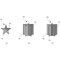
- FIG. 2A is a diagram illustrating a process of spraying different materials by the three-dimensional additive manufacturing apparatus 100 according to the present embodiment.
- the three-dimensional additive manufacturing apparatus 100 will be described as one that forms a star-shaped three-dimensional structure 180.
- the three-dimensional additive manufacturing apparatus 100 disperses the material (first material) 171 on the modeling surface 160.
- the material 171 is spread over the outer area of the star. Therefore, this state is a state in which the material 171 is dispersed and spread on the modeling surface 160 while leaving the inner region of the star shape.
- the material 171 is dispersed in an area where the beam 151 is not irradiated, and serves as a support material for the three-dimensional layered object 180 that is finally formed. Therefore, since the material 171 is finally removed, a relatively inexpensive material is used. For example, artificial quartz or iron is used, but the material 171 is not limited thereto. Further, the material 171 may be dispersed using a cartridge 102 having a nozzle portion having a relatively large aperture, for example, the cartridge 121.
- the three-dimensional additive manufacturing apparatus 100 disperses the material 172 and the material 173.
- the material 172 is dispersed in the lower left region of the star
- the material 173 is dispersed in the upper right region of the star, and both have a boundary and are dispersed in regions other than the region where the material 171 is dispersed. Is done. That is, the material 172 and the material 173 are dispersed in a modeling area where the three-dimensional layered object 180 is modeled.
- the material 172 and the material 173 may be accurately distributed using a cartridge 102 having a relatively small nozzle portion, for example, the cartridges 122 and 123.
- the three-dimensional additive manufacturing apparatus 100 irradiates the material 172 and the material 173 with the beam 151 to melt and solidify the material 172 and the material 173, thereby completing the stacking for one layer.
- the modeling surface 160 is lowered by one layer, and the spraying of the material 171, the material 172, and the material 173 is repeated as shown in FIGS. 2A (a) and 2 (b).
- FIG. 2B is a diagram illustrating a configuration of a three-dimensional structure 180 that is formed by the three-dimensional additive manufacturing apparatus 100 according to the present embodiment.
- 2B (a) is a top view
- FIGS. 2B (b) and 2B (c) are perspective views.
- the three-dimensional layered object 180 includes a object 182 made of the material 172 and a object 183 made of the material 173.
- the boundary 184 can be formed into an inclined structure by appropriately changing the concentration of the materials 172 and 173 in the vicinity of the boundary 184 between the modeled object 182 and the modeled object 183. .
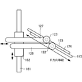
- FIG. 3A is a top view illustrating the configuration of the cartridge of the three-dimensional additive manufacturing apparatus according to the present embodiment and the state of material dispersion by the cartridge.
- FIG. 3B is a diagram for explaining a material dispersion region by the cartridge of the three-dimensional additive manufacturing apparatus according to the present embodiment.
- FIG. 4 is a diagram for explaining a material dispersion region by the cartridge of the three-dimensional additive manufacturing apparatus according to the present embodiment.
- the movement of the cartridge 122 and the cartridge 123 in the ⁇ direction is realized by simultaneously moving the X direction stage 161 and the Y direction stage 162 at the speeds of cos ⁇ and sin ⁇ , respectively.
- the material is dispersed from the cartridge 122 and the cartridge 123 in the form of a circle of the dispersed material 172 having a radius r and a circle of the dispersed material 173, respectively. If the cartridges 122 and 123 are moved in the ⁇ direction in this state, lines (or bands) of the dispersed materials 172 and 173 having a width of 2r are formed.
- the state where the boundary 175 (spread material 172) and the boundary 176 (spread material 173) formed by spraying the materials 172 and 173 from the respective cartridges 122 and 123 coincide is the two different types shown in FIG. 3A.
- a boundary 174 is formed by the materials 172 and 173.
- the boundary 174 is created in a state where the boundary 175 and the boundary 176 are in contact with each other.
- n indicates the number of times the cartridges 122 and 123 are moved (scanned) and continues until the spraying is completed.
- FIG. 5 is a top view illustrating another configuration of the cartridge of the three-dimensional additive manufacturing apparatus 100 according to the present embodiment.
- the X direction rail 163 is not necessary as shown in FIG. That is, if the lengths of the arms of the cartridge holders 126 and 127 are sufficiently long, the X direction stage 161 is fixed without moving the X direction stage 161 along the X direction rail 163. However, the same operation can be performed. In this case, the movement of the cartridges 122 and 123 in the X direction is performed using the cartridge holders 126 and 127.
- the adjustment is performed by adjusting the length of the arms of the cartridge holders 126 and 127, that is, by extending and contracting the arms.
- the boundary between the dispersed materials is a straight line
- the boundary can be formed by a curved line having an arbitrary shape by moving the cartridge 102 while changing ⁇ .
- FIG. 6A is a flowchart for explaining the material dispersion procedure of the three-dimensional additive manufacturing apparatus 100 according to the present embodiment.
- step S ⁇ b> 601 the three-dimensional additive manufacturing apparatus 100 spreads the material 171 on the non-irradiated region of the beam 151 on the modeling surface 160. That is, the three-dimensional additive manufacturing apparatus 100 disperses the material 171 serving as a support material over a predetermined area.
- step S ⁇ b> 603 the three-dimensional additive manufacturing apparatus 100 disperses a plurality of types of materials 172 and 173 in the irradiation area of the beam 151 on the modeling surface 160.
- the three-dimensional additive manufacturing apparatus 100 disperses the materials 172 and 173 that become the three-dimensional additive manufacturing object 180 in a predetermined region.
- the three-dimensional additive manufacturing apparatus 100 applies the beam 151 to the materials 172 and 173 in the irradiation region of the beam 151, and melts and solidifies the materials 172 and 173 to form the three-dimensional additive manufacturing object 180. To do.
- FIG. 6B is a flowchart for explaining the material spreading procedure (step S601) of the three-dimensional additive manufacturing apparatus according to this embodiment.
- step S ⁇ b> 611 the three-dimensional additive manufacturing apparatus 100 creates a distribution plan for the material 171 to be distributed in a region where the beam 151 is not irradiated.
- the layered modeling control unit 104 acquires the modeling data of the three-dimensional layered model 180 from the modeling data storage unit 145, and based on the acquired modeling data, the region where the beam 151 is not irradiated (beam non-irradiated region).
- a spray plan for the material 171 to be sprayed is created.
- the spraying plan includes, for example, the spraying timing of the material 171 by the cartridge 121, the replenishment timing of the material 171 from the material supplier 131, and the like.
- step S613 the three-dimensional additive manufacturing apparatus 100 disperses the material 171 in an area where the beam 151 is not irradiated according to the created distribution plan.
- the additive manufacturing control unit 104 transmits a control signal according to the created distribution plan to the cartridge position control unit 141, the cartridge control unit 142, the powder supply control unit 144, and the like.
- the cartridge position control unit 141, the cartridge control unit 142, the powder supply control unit 144, and the like that have received the control signal control the movement of the cartridge 102 and the like so as to perform an operation according to the distribution plan. That is, the cartridge 171 storing the material 171 is scanned on the modeling surface 160 to spread the material 171.
- the cartridge 121 stops spraying the material 171.
- the cartridge 121 stops spraying the material 171.
- the spraying of the material 171 is resumed from the interrupted position.
- step S615 the cartridge control unit 142 of the three-dimensional additive manufacturing apparatus 100 determines whether or not the amount of remaining material in the cartridge 121 is equal to or greater than the lower limit. If the remaining material amount is equal to or greater than the lower limit, the three-dimensional additive manufacturing apparatus 100 continues to spray the material 171. If the remaining material amount is not greater than or equal to the lower limit, that is, if the remaining material amount is less than the lower limit, the three-dimensional additive manufacturing apparatus 100 proceeds to step S621.
- step S621 the three-dimensional additive manufacturing apparatus 100 stops (interrupts) the dispersion of the material 171 and stores the position on the modeling surface 160 of the cartridge 121.
- step S623 the three-dimensional additive manufacturing apparatus 100 moves the cartridge 121 to the material supply position, that is, the position below the material supply unit 131.
- the additive manufacturing control unit 104 of the three-dimensional additive manufacturing apparatus 100 controls the powder supply control unit 144 to supply the material 171 from the material supplier 131 to the cartridge 121 and replenish the material 171.
- the replenishment amount of the material 171 may be an amount up to the upper limit of the remaining material of the cartridge 121, or an amount necessary for spraying the remaining material.
- step S617 the three-dimensional additive manufacturing apparatus 100 determines whether or not the created spray plan has been completed. If it is determined that the spraying plan has not ended, the three-dimensional additive manufacturing apparatus 100 repeats the processes after step S613. When it is determined that the spraying plan has been completed, the three-dimensional additive manufacturing apparatus 100 returns the cartridge 121 to the material supply position below the material supplier 131, replenishes the material 171 up to the upper limit of the remaining material, The cartridge 121 is kept on standby until modeling is started.
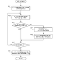
- FIG. 6C is a flowchart for explaining the material dispersion procedure (step S603) of the three-dimensional additive manufacturing apparatus according to the present embodiment.
- step S ⁇ b> 631 the three-dimensional additive manufacturing apparatus 100 creates a distribution plan for the materials 172 and 173 to be distributed in the region irradiated with the beam 151.
- the layered modeling control unit 104 acquires modeling data of the three-dimensional layered model 180 from the modeling data storage unit 145, and irradiates the beam 151 based on the acquired modeling data (beam irradiation region).
- a spraying plan for the materials 172 and 173 to be sprayed is created.
- the spraying plan includes, for example, the spraying timing of the materials 172 and 173 by the cartridges 122 and 123, the replenishment timing of the materials 172 and 173 from the material feeders 132 and 133, and the like.
- step S633 the three-dimensional additive manufacturing apparatus 100 disperses the materials 172 and 173 in the region irradiated with the beam 151 according to the created dispersal plan.
- the additive manufacturing control unit 104 transmits a control signal according to the created distribution plan to the cartridge position control unit 141, the cartridge control unit 142, the powder supply control unit 144, and the like.
- the cartridge position control unit 141, the cartridge control unit 142, the powder supply control unit 144, and the like that have received the control signal control the movement of the cartridges 122, 123 and the like so as to perform an operation according to the distribution plan. That is, the cartridges 122 and 123 storing the materials 172 and 173 are scanned on the modeling surface 160 to spread the materials 172 and 173.
- the cartridges 122 and 123 stop spraying the materials 172 and 173.
- the cartridges 122 and 123 stop spraying the materials 172 and 173.
- the spraying of the materials 172 and 173 is resumed from the position where the interruption occurred.
- step S635 the cartridge controller 142 of the three-dimensional additive manufacturing apparatus 100 determines whether or not the amount of remaining material in the cartridges 122 and 123 is equal to or greater than the lower limit. If the residual material amount is equal to or greater than the lower limit, the three-dimensional additive manufacturing apparatus 100 continues to spray the materials 172 and 173. If the remaining material amount is not equal to or greater than the lower limit, that is, if the remaining material amount is less than the lower limit, the three-dimensional additive manufacturing apparatus 100 proceeds to step S641.
- step S641 the three-dimensional additive manufacturing apparatus 100 stops (interrupts) the dispersion of the materials 172 and 173 and stores the positions of the cartridges 122 and 123 on the modeling surface 160.
- step S643 the three-dimensional additive manufacturing apparatus 100 moves the cartridges 122 and 123 to the material supply position, that is, the position below the material supply units 132 and 133.
- the additive manufacturing control unit 104 of the three-dimensional additive manufacturing apparatus 100 controls the powder supply control unit 144 to supply the materials 172 and 173 from the material supply units 132 and 133 to the cartridges 122 and 123.
- Material 172, 173 is replenished.
- the replenishment amount of the materials 172 and 173 may be an amount up to the upper limit of the remaining material of the cartridges 122 and 123, or may be an amount necessary for spraying the remaining material.
- step S637 the three-dimensional additive manufacturing apparatus 100 determines whether or not the created distribution plan has been completed. If it is determined that the spraying plan has not ended, the three-dimensional additive manufacturing apparatus 100 repeats the processing from step S633. If it is determined that the spraying plan has been completed, the three-dimensional additive manufacturing apparatus 100 returns the cartridges 122 and 123 to the material supply positions at the lower positions of the material supply units 132 and 133. Then, the materials 172 and 173 are replenished up to the upper limit of the remaining material, and the cartridges 122 and 123 are put on standby until the next modeling is started.
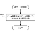
- FIG. 6D is a flowchart for explaining the material dispersion procedure (step S605) of the three-dimensional additive manufacturing apparatus according to the present embodiment.
- step S651 the three-dimensional additive manufacturing apparatus 100 applies the beam 151 to the materials 172 and 173 in the beam irradiation region, melts and solidifies the materials 172 and 173, and forms the three-dimensional additive manufacturing object 180.
- FIG. 7A is a diagram for explaining the configuration of the material supplier of the three-dimensional additive manufacturing apparatus according to the present embodiment, and is a front view seen from the chamber 101 side.
- the material supplier 103 includes a plurality of material suppliers, that is, a material supplier 131 (first material supplier), a material supplier 132 (second material supplier), a material supplier 133 (third material supplier), and A material supplier 134 (fourth material supplier) is included.
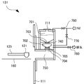
- FIG. 7B is a diagram illustrating the configuration of the material supplier of the three-dimensional additive manufacturing apparatus according to the present embodiment, and is a schematic side sectional view of the material supplier 131.
- the material supplier 131 is attached to the chamber wall 111 of the chamber 101 and includes a material storage unit 701, an intermediate material storage unit 702, and valves 703, 704, and 705.
- the inside of the chamber 101 is evacuated to a vacuum.
- the cartridge 121 is described as an example, but the same applies to the other cartridges 122, 123, and 124.
- the cartridge 121 In the chamber 101, there is a cartridge 121 that spreads the material 171 on the modeling surface 160 above the modeling surface 160, and the cartridge 121 is held by a cartridge holder 125. Since the cartridge holder 125 is attached to a Y-direction stage 162 (not shown), and the Y-direction stage 162 is attached to the X-direction stage 161, the material 171 is distributed two-dimensionally on the modeling surface 160. can do.
- the cartridge 121 can store a predetermined amount of material 171 therein. However, the amount of the material 171 that can be stored in the cartridge 121 cannot store the amount of the material 171 necessary for modeling the three-dimensional laminate 180, and the insufficient material 171 must be replenished as needed.
- the material supplier 131 includes a material storage unit 701 on the upstream side, and an intermediate material storage unit 702 on the downstream side of the material storage unit 701.
- a valve 703 (first valve) is provided between the material storage unit 701 and the intermediate material storage unit 702. By controlling the opening and closing of the valve 703, the material storage unit 701 and the intermediate material storage unit 702 Opening or shutting off can be controlled.
- the material 171 stored in the material storage unit 701 falls downward, and the material 171 can be supplied to the intermediate material storage unit 702.
- the lower part (bottom part) of the material storage part 701 is a taper shape, the material 171 will fall naturally downward with dead weight only by opening the valve
- a hole for replenishing the material 171 from the outside is formed in the upper part of the material storage unit 701. Normally, this hole is sealed by a sealing lid 711.
- an introduction pipe for introducing an inert gas such as nitrogen (N 2 ) is attached to the material storage unit 701, and the inert gas can be introduced by opening and closing the on-off valve 760.
- the inside of the material storage unit 701 is filled with an inert gas such as nitrogen in order to prevent contamination of the stored material 171.
- the intermediate material storage unit 702 is provided inside the exchange chamber 740 and temporarily stores the material 171 supplied from the material storage unit 701. Similarly to the material storage unit 701, the intermediate material storage unit 702 has a tapered lower part (bottom), so that the material 171 can be supplied to the cartridge 121 by controlling the opening and closing of the valves 704 and 705.
- a pipe for introducing an inert gas such as nitrogen is attached to the intermediate material storage unit 702, and the inert gas can be introduced into the intermediate material storage unit 702 by opening and closing the on-off valve 770.
- a pipe for vacuum exhaust is attached to the intermediate material storage unit 702, and the intermediate material storage unit 702 can be exhausted to a vacuum by opening and closing the on-off valve 780.
- FIGS. 8A to 8D are views for explaining the state of material supply by the material supplier of the three-dimensional additive manufacturing apparatus according to the present embodiment.
- the material feeder 131 will be described, but the same applies to the other material feeders 132, 133, and 134.
- the material storage unit 701 is filled with an inert gas.
- the intermediate material storage unit 702 does not store the material 171.
- the valve 703, the valve 704, and the valve 705 are all closed.
- the on-off valve 760 and the on-off valve 770 are opened, and the on-off valve 780 is closed. Therefore, since the on-off valve 760 and the on-off valve 770 are opened, the material storage unit 701 and the intermediate material storage unit 702 have the same atmosphere.
- the valve 703 is closed to stop the supply of the material 171
- the on-off valve 780 is opened, the inside of the exchange chamber 740 is evacuated, and the vacuum is made.
- the exchange chamber 740 continues to be exhausted until the degree of vacuum in the exchange chamber 740 becomes the same as the degree of vacuum in the chamber 101.
- the evacuation of the exchange chamber 740 may be performed while the cartridge 121 is spraying the material 171. In this way, by using the time during which the cartridge 121 is spraying the material 171, the intermediate storage unit 702 is replenished with the material 171 and the exchange chamber 740 is evacuated to a vacuum. Modeling time can be shortened.
- a three-dimensional structure using a plurality of different materials can be formed, and further, the material can be replenished during the formation without stopping the apparatus. Further, if the number of cartridges is increased, multicolor printing corresponding to the number of cartridges can be performed. Furthermore, an intermediate material storage unit is provided in the material supplier, and the atmosphere is adjusted to make the same degree of vacuum as that of the chamber in advance, so that it is possible to model a three-dimensional layered object without stopping the operation of the three-dimensional layered object modeling apparatus. This can shorten the modeling time.
- FIG. 9 is a diagram for explaining the configuration of the material supplier of the three-dimensional additive manufacturing apparatus according to the present embodiment.
- the three-dimensional additive manufacturing apparatus according to the present embodiment is different from the first embodiment in that it has a bottle. Since other configurations and operations are the same as those of the first embodiment, the same configurations and operations are denoted by the same reference numerals and detailed description thereof is omitted.
- the material supplier 931 has a bottle 901. For example, if the amount of the material 171 necessary for modeling the three-dimensional layered object 180 is stored in the bottle 901, it is not necessary to replenish the material storage unit 701 with the material 171 during the modeling.
- the bottle is provided in the material supplier, a predetermined amount of material can be continuously supplied to the cartridge.
- a predetermined amount of material can be continuously supplied to the cartridge.
- it is not necessary to replenish materials during the modeling it is not necessary to stop the operation of the three-dimensional layered modeling apparatus, and the modeling time can be shortened.
- FIG. 10 is a diagram for explaining the configuration of the material supplier of the three-dimensional additive manufacturing apparatus according to the present embodiment.
- the three-dimensional additive manufacturing apparatus according to the present embodiment is different from the first embodiment and the second embodiment in that a material transporter is provided. Since other configurations and operations are the same as those in the first embodiment and the second embodiment, the same configurations and operations are denoted by the same reference numerals, and detailed description thereof is omitted.
- the material feeder 1031 has a material transporter 1001.
- the material transporter 1001 can continuously supply the material 171 to the material storage unit 701 by, for example, pressure feeding. Therefore, even in the case of a three-dimensional layered object 180 that requires a large amount of material 171, modeling can be continued without stopping the three-dimensional layered object modeling apparatus for replenishment of the material 171, thereby shortening the modeling time. it can.
- the material feeder since the material feeder is provided in the material feeder, the material can be continuously conveyed to the cartridge, and the modeling time of the three-dimensional layered object can be shortened.
- FIG. 11 is a diagram for explaining the configuration of the three-dimensional additive manufacturing apparatus according to the present embodiment.
- the three-dimensional additive manufacturing apparatus 1100 according to the present embodiment is different from the first embodiment in that the cartridge is replaceable. Since other configurations and operations are the same as those of the first embodiment, the same configurations and operations are denoted by the same reference numerals and detailed description thereof is omitted.
- the cartridges 121, 122, 123, and 124 are held by a cartridge holder 1125, and the cartridge holder 1125 is further attached to an XY direction rail 1164.
- the XY direction rail 1164 drives the cartridge holder 1125 in the XY direction, that is, two-dimensionally.
- the cartridges 121, 122, 123, and 124 are filled with different types of materials 171, 172, 173, and 174, respectively.
- the cartridges 121, 122, 123, and 124 may all be filled with the same type of material, or some may be the same type of material and others may be different types of material.
- the cartridges 121, 122, 123, and 124 are structured to be removable from the cartridge holder 1125.
- the cartridges 121, 122, 123, and 124 may have a structure that can be removed one by one or a structure that can remove four cartridges as one set.
- the number of cartridges is not limited to four, but may be two or more.
- the apparatus configuration of the three-dimensional additive manufacturing apparatus becomes very simple. Further, when the material needs to be replenished, the cartridge itself may be replaced, so that the material replenishment time can be greatly shortened.
- the present invention may be applied to a system composed of a plurality of devices, or may be applied to a single device. Furthermore, the present invention can also be applied to a case where an information processing program that implements the functions of the embodiments is supplied directly or remotely to a system or apparatus. Therefore, in order to realize the functions of the present invention on a computer, a program installed on the computer, a medium storing the program, and a WWW (World Wide Web) server that downloads the program are also included in the scope of the present invention. . In particular, at least a non-transitory computer readable medium storing a program for causing a computer to execute the processing steps included in the above-described embodiments is included in the scope of the present invention.
Landscapes
- Engineering & Computer Science (AREA)
- Chemical & Material Sciences (AREA)
- Materials Engineering (AREA)
- Manufacturing & Machinery (AREA)
- Physics & Mathematics (AREA)
- Optics & Photonics (AREA)
- Mechanical Engineering (AREA)
- Automation & Control Theory (AREA)
- Plasma & Fusion (AREA)
- Powder Metallurgy (AREA)
Abstract
Description
3次元積層造形物が造形される造形室と、
前記造形室内に設けられ、前記3次元積層造形物の材料を散布する少なくとも2つの材料散布手段と、
前記材料散布手段に前記材料を供給する少なくとも2つの材料供給手段と、
前記材料散布手段および前記材料供給手段の動きを制御する制御手段と、
前記材料にビームを照射するビーム照射手段と、
を備え、
前記材料散布手段と前記材料供給手段とは、それぞれ対をなし、
前記制御手段は、前記材料散布手段が、対となる前記材料供給手段から所定のタイミングで前記材料の供給を受けられるように前記材料散布手段および前記材料供給手段の動きを制御する。 In order to achieve the above object, a three-dimensional additive manufacturing apparatus according to the present invention
A modeling room where a three-dimensional layered object is modeled;
Provided in the modeling chamber, and at least two material distribution means for distributing the material of the three-dimensional layered object; and
At least two material supply means for supplying the material to the material distribution means;
Control means for controlling the movement of the material spraying means and the material supply means;
Beam irradiation means for irradiating the material with a beam;
With
The material spreading means and the material supply means make a pair,
The control means controls the movement of the material spraying means and the material supply means so that the material spraying means can receive the supply of the material at a predetermined timing from the paired material supply means.
3次元積層造形物が造形される造形室と、
前記造形室内に設けられ、前記3次元積層造形物の材料を散布する少なくとも2つの材料散布手段と、
前記材料散布手段に前記材料を供給する少なくとも2つの材料供給手段と、
前記材料散布手段の動きを制御する制御手段と、
前記材料にビームを照射するビーム照射手段と、
を備え、
前記材料散布手段と前記材料供給手段とは、それぞれ対をなす、3次元積層造形装置の制御方法であって、
前記材料散布手段が、対となる前記材料供給手段から所定のタイミングで前記材料の供給を受けられるように前記材料散布手段の動きを制御する制御ステップを含む。 In order to achieve the above object, a method for controlling a three-dimensional additive manufacturing apparatus according to the present invention includes:
A modeling room where a three-dimensional layered object is modeled;
Provided in the modeling chamber, and at least two material distribution means for distributing the material of the three-dimensional layered object; and
At least two material supply means for supplying the material to the material distribution means;
Control means for controlling the movement of the material spraying means;
Beam irradiation means for irradiating the material with a beam;
With
The material spraying means and the material supply means are each a control method of a three-dimensional additive manufacturing apparatus that makes a pair,
The material spraying means includes a control step of controlling the movement of the material spraying means so that the material supply means can receive the supply of the material at a predetermined timing from the paired material supply means.
3次元積層造形物が造形される造形室と、
前記造形室内に設けられ、前記3次元積層造形物の材料を散布する少なくとも2つの材料散布手段と、
前記材料散布手段に前記材料を供給する少なくとも2つの材料供給手段と、
前記材料散布手段の動きを制御する制御手段と、
前記材料にビームを照射するビーム照射手段と、
を備え、
前記材料散布手段と前記材料供給手段とは、それぞれ対をなす、3次元積層造形装置の制御プログラムであって、
前記材料散布手段が、対となる前記材料供給手段から所定のタイミングで前記材料の供給を受けられるように前記材料散布手段の動きを制御する制御ステップをコンピュータに実行させる。 In order to achieve the above object, a control program for a three-dimensional additive manufacturing apparatus according to the present invention is:
A modeling room where a three-dimensional layered object is modeled;
Provided in the modeling chamber, and at least two material distribution means for distributing the material of the three-dimensional layered object; and
At least two material supply means for supplying the material to the material distribution means;
Control means for controlling the movement of the material spraying means;
Beam irradiation means for irradiating the material with a beam;
With
The material distribution means and the material supply means are a control program for a three-dimensional additive manufacturing apparatus that makes a pair,
The computer causes the computer to execute a control step of controlling the movement of the material spraying means so that the material supply means can receive the supply of the material from the paired material supply means at a predetermined timing.
本発明の第1実施形態としての3次元積層造形装置100について、図1を用いて説明する。図1は、本実施形態に係る3次元積層造形装置100の構成を説明する図である。なお、同図においては、図が煩雑になるのを避けるため、同図に示した以外の構成については適宜省略している。3次元積層造形装置100は、造形面160上に3次元積層造形物180の材料170を散布し、散布した材料170に電子ビーム170などを照射して、材料170を溶融および凝固させることにより、材料170を積層して3次元積層造形物180を造形する装置である。 [First Embodiment]
A three-dimensional
ΔX=F(Ds,θ)=(Da/tanθ)-((Ds+2r)/sinθ) (1) If the distance in the X direction between the center of the
ΔX = F (Ds, θ) = (Da / tan θ) − ((Ds + 2r) / sin θ) (1)
次に本発明の第2実施形態に係る3次元積層造形装置について、図9を用いて説明する。図9は、本実施形態に係る3次元積層造形装置の材料供給器の構成を説明するための図である。本実施形態に係る3次元積層造形装置は、上記第1実施形態と比べると、ボトルを有する点で異なる。その他の構成および動作は、第1実施形態と同様であるため、同じ構成および動作については同じ符号を付してその詳しい説明を省略する。 [Second Embodiment]
Next, a three-dimensional additive manufacturing apparatus according to a second embodiment of the present invention will be described with reference to FIG. FIG. 9 is a diagram for explaining the configuration of the material supplier of the three-dimensional additive manufacturing apparatus according to the present embodiment. The three-dimensional additive manufacturing apparatus according to the present embodiment is different from the first embodiment in that it has a bottle. Since other configurations and operations are the same as those of the first embodiment, the same configurations and operations are denoted by the same reference numerals and detailed description thereof is omitted.
次に本発明の第3実施形態に係る3次元積層造形装置について、図10を用いて説明する。図10は、本実施形態に係る3次元積層造形装置の材料供給器の構成を説明するための図である。本実施形態に係る3次元積層造形装置は、上記第1実施形態および第2実施形態と比べると、材料搬送器を有する点で異なる。その他の構成および動作は、第1実施形態および第2実施形態と同様であるため、同じ構成および動作については同じ符号を付してその詳しい説明を省略する。 [Third Embodiment]
Next, a three-dimensional additive manufacturing apparatus according to a third embodiment of the present invention will be described with reference to FIG. FIG. 10 is a diagram for explaining the configuration of the material supplier of the three-dimensional additive manufacturing apparatus according to the present embodiment. The three-dimensional additive manufacturing apparatus according to the present embodiment is different from the first embodiment and the second embodiment in that a material transporter is provided. Since other configurations and operations are the same as those in the first embodiment and the second embodiment, the same configurations and operations are denoted by the same reference numerals, and detailed description thereof is omitted.
次に本発明の第4実施形態に係る について、図11を用いて説明する。図11は、本実施形態に係る3次元積層造形装置の構成を説明するための図である。本実施形態に係る3次元積層造形装置1100は、上記第1実施形態と比べると、カートリッジが交換式である点で異なる。その他の構成および動作は、第1実施形態と同様であるため、同じ構成および動作については同じ符号を付してその詳しい説明を省略する。 [Fourth Embodiment]
Next, according to the fourth embodiment of the present invention will be described with reference to FIG. FIG. 11 is a diagram for explaining the configuration of the three-dimensional additive manufacturing apparatus according to the present embodiment. The three-dimensional
以上、実施形態を参照して本願発明を説明したが、本願発明は上記実施形態に限定されるものではない。本願発明の構成や詳細には、本願発明のスコープ内で当業者が理解し得る様々な変更をすることができる。また、それぞれの実施形態に含まれる別々の特徴を如何様に組み合わせたシステムまたは装置も、本発明の範疇に含まれる。 [Other Embodiments]
While the present invention has been described with reference to the embodiments, the present invention is not limited to the above embodiments. Various changes that can be understood by those skilled in the art can be made to the configuration and details of the present invention within the scope of the present invention. In addition, a system or an apparatus in which different features included in each embodiment are combined in any way is also included in the scope of the present invention.
Claims (9)
- 3次元積層造形物が造形される造形室と、
前記造形室内に設けられ、前記3次元積層造形物の材料を散布する少なくとも2つの材料散布手段と、
前記材料散布手段に前記材料を供給する少なくとも2つの材料供給手段と、
前記材料散布手段および前記材料供給手段の動きを制御する制御手段と、
前記材料にビームを照射するビーム照射手段と、
を備え、
前記材料散布手段と前記材料供給手段とは、それぞれ対をなし、
前記制御手段は、前記材料散布手段が、対となる前記材料供給手段から所定のタイミングで前記材料の供給を受けられるように前記材料散布手段および前記材料供給手段の動きを制御する3次元積層造形装置。 A modeling room where a three-dimensional layered object is modeled;
Provided in the modeling chamber, and at least two material distribution means for distributing the material of the three-dimensional layered object; and
At least two material supply means for supplying the material to the material distribution means;
Control means for controlling the movement of the material spraying means and the material supply means;
Beam irradiation means for irradiating the material with a beam;
With
The material spreading means and the material supply means make a pair,
The control means controls the movement of the material distribution means and the material supply means so that the material distribution means can be supplied with the material from the paired material supply means at a predetermined timing. apparatus. - 前記材料供給手段は、上流側に設けられた材料貯蔵手段と、下流側に設けられた中間材料貯蔵手段とを有し、前記材料貯蔵手段と前記中間材料貯蔵手段とは第1バルブを介して接続され、前記中間貯蔵手段と前記造形室とは第2バルブを介して接続され、
前記第1バルブおよび前記第2バルブの開閉を制御するバルブ制御手段と、
前記中間貯蔵手段の内部の雰囲気と、前記造形室の内部の雰囲気とを制御する雰囲気制御手段と、
をさらに備える請求項1に記載の3次元積層造形装置。 The material supply means includes a material storage means provided on the upstream side and an intermediate material storage means provided on the downstream side, and the material storage means and the intermediate material storage means are connected via a first valve. Connected, the intermediate storage means and the modeling chamber are connected via a second valve,
Valve control means for controlling opening and closing of the first valve and the second valve;
Atmosphere control means for controlling the atmosphere inside the intermediate storage means and the atmosphere inside the modeling chamber;
The three-dimensional additive manufacturing apparatus according to claim 1, further comprising: - 前記雰囲気制御手段は、前記中間材料貯蔵手段の内部を真空排気する請求項2に記載の3次元積層造形装置。 3. The three-dimensional additive manufacturing apparatus according to claim 2, wherein the atmosphere control means evacuates the inside of the intermediate material storage means.
- 前記雰囲気制御手段は、前記中間材料貯蔵手段の内部の雰囲気と、前記造形室の内部の雰囲気とを同じ雰囲気にする請求項2に記載の3次元積層造形装置。 3. The three-dimensional additive manufacturing apparatus according to claim 2, wherein the atmosphere control means makes the atmosphere inside the intermediate material storage means and the atmosphere inside the modeling chamber the same atmosphere.
- 前記材料散布手段の一方は、前記ビームが照射されない材料を散布し、他方は、前記ビームが照射される材料を散布する請求項1乃至4のいずれか1項に記載の3次元積層造形装置。 The three-dimensional additive manufacturing apparatus according to any one of claims 1 to 4, wherein one of the material spraying means sprays a material that is not irradiated with the beam, and the other sprays a material that is irradiated with the beam.
- 前記ビームは、電子ビーム、レーザビームまたはイオンビームである請求項1乃至5のいずれか1項に記載の3次元積層造形装置。 The three-dimensional additive manufacturing apparatus according to any one of claims 1 to 5, wherein the beam is an electron beam, a laser beam, or an ion beam.
- 前記ビームは、連続ビームまたはパルスビームである請求項1乃至6のいずれか1項に記載の3次元積層造形装置。 The three-dimensional additive manufacturing apparatus according to any one of claims 1 to 6, wherein the beam is a continuous beam or a pulse beam.
- 3次元積層造形物が造形される造形室と、
前記造形室内に設けられ、前記3次元積層造形物の材料を散布する少なくとも2つの材料散布手段と、
前記材料散布手段に前記材料を供給する少なくとも2つの材料供給手段と、
前記材料散布手段の動きを制御する制御手段と、
前記材料にビームを照射するビーム照射手段と、
を備え、
前記材料散布手段と前記材料供給手段とは、それぞれ対をなす、3次元積層造形装置の制御方法であって、
前記材料散布手段が、対となる前記材料供給手段から所定のタイミングで前記材料の供給を受けられるように前記材料散布手段の動きを制御する制御ステップを含む3次元積層造形装置の制御方法。 A modeling room where a three-dimensional layered object is modeled;
Provided in the modeling chamber, and at least two material distribution means for distributing the material of the three-dimensional layered object; and
At least two material supply means for supplying the material to the material distribution means;
Control means for controlling the movement of the material spraying means;
Beam irradiation means for irradiating the material with a beam;
With
The material spraying means and the material supply means are each a control method of a three-dimensional additive manufacturing apparatus that makes a pair,
A control method for a three-dimensional additive manufacturing apparatus, comprising: a control step of controlling movement of the material spraying unit so that the material spraying unit can receive supply of the material at a predetermined timing from the material supply unit as a pair. - 3次元積層造形物が造形される造形室と、
前記造形室内に設けられ、前記3次元積層造形物の材料を散布する少なくとも2つの材料散布手段と、
前記材料散布手段に前記材料を供給する少なくとも2つの材料供給手段と、
前記材料散布手段の動きを制御する制御手段と、
前記材料にビームを照射するビーム照射手段と、
を備え、
前記材料散布手段と前記材料供給手段とは、それぞれ対をなす、3次元積層造形装置の制御プログラムであって、
前記材料散布手段が、対となる前記材料供給手段から所定のタイミングで前記材料の供給を受けられるように前記材料散布手段の動きを制御する制御ステップをコンピュータに実行させる3次元積層造形装置の制御プログラム。 A modeling room where a three-dimensional layered object is modeled;
Provided in the modeling chamber, and at least two material distribution means for distributing the material of the three-dimensional layered object; and
At least two material supply means for supplying the material to the material distribution means;
Control means for controlling the movement of the material spraying means;
Beam irradiation means for irradiating the material with a beam;
With
The material distribution means and the material supply means are a control program for a three-dimensional additive manufacturing apparatus that makes a pair,
Control of a three-dimensional additive manufacturing apparatus that causes a computer to execute a control step of controlling the movement of the material spraying unit so that the material spraying unit can receive the supply of the material from the paired material supply unit at a predetermined timing. program.
Priority Applications (4)
| Application Number | Priority Date | Filing Date | Title |
|---|---|---|---|
| EP15899114.1A EP3210756A4 (en) | 2015-12-25 | 2015-12-25 | Three-dimensional additive manufacturing device, control method of three-dimensional additive manufacturing device, and control program of three-dimensional additive manufacturing device |
| PCT/JP2015/086306 WO2017109966A1 (en) | 2015-12-25 | 2015-12-25 | Three-dimensional additive manufacturing device, control method of three-dimensional additive manufacturing device, and control program of three-dimensional additive manufacturing device |
| JP2016510879A JP6050551B1 (en) | 2015-12-25 | 2015-12-25 | Control method for three-dimensional additive manufacturing apparatus, control method for three-dimensional additive manufacturing apparatus, and control program for three-dimensional additive manufacturing apparatus |
| US15/118,386 US10406748B2 (en) | 2015-12-25 | 2015-12-25 | Three-dimensional laminating and shaping apparatus, control method of three-dimensional laminating and shaping apparatus, and control program of three-dimensional laminating and shaping apparatus |
Applications Claiming Priority (1)
| Application Number | Priority Date | Filing Date | Title |
|---|---|---|---|
| PCT/JP2015/086306 WO2017109966A1 (en) | 2015-12-25 | 2015-12-25 | Three-dimensional additive manufacturing device, control method of three-dimensional additive manufacturing device, and control program of three-dimensional additive manufacturing device |
Publications (1)
| Publication Number | Publication Date |
|---|---|
| WO2017109966A1 true WO2017109966A1 (en) | 2017-06-29 |
Family
ID=57572469
Family Applications (1)
| Application Number | Title | Priority Date | Filing Date |
|---|---|---|---|
| PCT/JP2015/086306 WO2017109966A1 (en) | 2015-12-25 | 2015-12-25 | Three-dimensional additive manufacturing device, control method of three-dimensional additive manufacturing device, and control program of three-dimensional additive manufacturing device |
Country Status (4)
| Country | Link |
|---|---|
| US (1) | US10406748B2 (en) |
| EP (1) | EP3210756A4 (en) |
| JP (1) | JP6050551B1 (en) |
| WO (1) | WO2017109966A1 (en) |
Families Citing this family (17)
| Publication number | Priority date | Publication date | Assignee | Title |
|---|---|---|---|---|
| WO2018227229A1 (en) * | 2017-06-15 | 2018-12-20 | AmPro Innovations Pty Ltd | Improved additive manufacturing of metallic components |
| CN107650377B (en) * | 2017-09-13 | 2020-08-18 | 北京碧如蓝工贸公司 | 3D printer nozzle and 3D printer |
| KR20220124281A (en) * | 2017-10-16 | 2022-09-13 | 트러스티즈 오브 터프츠 칼리지 | System and method for making microneedles |
| GB2569649B (en) * | 2017-12-22 | 2020-06-10 | Reliance Prec Limited | Powder supply in additive layer manufacturing apparatus |
| US10828832B2 (en) * | 2018-09-28 | 2020-11-10 | The Boeing Company | Powder dispensing unit, powder spreading unit, and a vibratory compaction system of an additive manufacturing system and methods therefor |
| US10814555B2 (en) * | 2018-09-28 | 2020-10-27 | The Boeing Company | Powder dispensing unit, powder spreading unit, and a vibratory compaction system of an additive manufacturing system and methods therefor |
| US10814552B2 (en) * | 2018-09-28 | 2020-10-27 | The Boeing Company | Powder dispensing unit, powder spreading unit, and a vibratory compaction system of an additive manufacturing system and methods therefor |
| US10894360B2 (en) * | 2018-09-28 | 2021-01-19 | The Boeing Company | Powder dispensing unit, powder spreading unit, and a vibratory compaction system of an additive manufacturing system and methods therefor |
| US11712851B2 (en) * | 2018-10-16 | 2023-08-01 | Hewlett-Packard Development Company, L.P. | Material dispensing apparatus |
| DE102019219083A1 (en) * | 2019-12-06 | 2021-06-10 | Robert Bosch Gmbh | Printing device for a 3D printer |
| US11766832B2 (en) * | 2020-05-13 | 2023-09-26 | The Boeing Company | System and method for additively manufacturing an object |
| US11951679B2 (en) | 2021-06-16 | 2024-04-09 | General Electric Company | Additive manufacturing system |
| US11731367B2 (en) | 2021-06-23 | 2023-08-22 | General Electric Company | Drive system for additive manufacturing |
| US11958250B2 (en) | 2021-06-24 | 2024-04-16 | General Electric Company | Reclamation system for additive manufacturing |
| US11958249B2 (en) | 2021-06-24 | 2024-04-16 | General Electric Company | Reclamation system for additive manufacturing |
| US11826950B2 (en) | 2021-07-09 | 2023-11-28 | General Electric Company | Resin management system for additive manufacturing |
| US11813799B2 (en) | 2021-09-01 | 2023-11-14 | General Electric Company | Control systems and methods for additive manufacturing |
Citations (8)
| Publication number | Priority date | Publication date | Assignee | Title |
|---|---|---|---|---|
| JPH10211658A (en) * | 1997-01-31 | 1998-08-11 | Toyota Motor Corp | Powdery particle laminate shaping method and apparatus therefor |
| JP2000085019A (en) * | 1998-09-09 | 2000-03-28 | Sanyo Electric Co Ltd | Method and apparatus for treating step of fabricated article |
| JP2001047520A (en) * | 1999-08-04 | 2001-02-20 | Toyota Motor Corp | Method for lamination shaping |
| JP2005014556A (en) * | 2003-06-30 | 2005-01-20 | Ricoh Printing Systems Ltd | Three-dimensionally shaping equipment |
| JP2005504653A (en) * | 2001-10-03 | 2005-02-17 | スリーディー システムズ インコーポレーテッド | Quantization feeder for solid freeform fabrication |
| JP2006509914A (en) | 2002-12-13 | 2006-03-23 | アルカム アーベー | 3D product manufacturing equipment |
| JP2007118612A (en) * | 1997-04-28 | 2007-05-17 | Three D Syst Inc | Method for controlling exposure of a solidifiable medium using a pulsed radiation source in building a three-dimensional object by stereolithography |
| JP2015101739A (en) * | 2013-11-21 | 2015-06-04 | 国立研究開発法人産業技術総合研究所 | Apparatus for manufacturing laminated structure of molten layers, method for manufacturing laminated structure of molten layers, and laminated structure of molten layers |
Family Cites Families (9)
| Publication number | Priority date | Publication date | Assignee | Title |
|---|---|---|---|---|
| CA2227672A1 (en) | 1997-01-29 | 1998-07-29 | Toyota Jidosha Kabushiki Kaisha | Method for producing a laminated object and apparatus for producing the same |
| US5993554A (en) * | 1998-01-22 | 1999-11-30 | Optemec Design Company | Multiple beams and nozzles to increase deposition rate |
| DE102005014483B4 (en) * | 2005-03-30 | 2019-06-27 | Realizer Gmbh | Device for the production of articles by layering of powdered material |
| US8245757B2 (en) | 2009-02-02 | 2012-08-21 | Stratasys, Inc. | Inorganic ionic support materials for digital manufacturing systems |
| US8955558B2 (en) * | 2012-06-18 | 2015-02-17 | Stratasys, Inc. | Hopper valve for extrusion-based additive manufacturing systems, and methods of use thereof |
| US9561542B2 (en) * | 2012-11-06 | 2017-02-07 | Arcam Ab | Powder pre-processing for additive manufacturing |
| JP2015182252A (en) | 2014-03-20 | 2015-10-22 | 日本電子株式会社 | Three-dimensional laminate molding apparatus |
| US9643361B2 (en) * | 2014-05-27 | 2017-05-09 | Jian Liu | Method and apparatus for three-dimensional additive manufacturing with a high energy high power ultrafast laser |
| US9676145B2 (en) * | 2015-11-06 | 2017-06-13 | Velo3D, Inc. | Adept three-dimensional printing |
-
2015
- 2015-12-25 EP EP15899114.1A patent/EP3210756A4/en not_active Withdrawn
- 2015-12-25 JP JP2016510879A patent/JP6050551B1/en active Active
- 2015-12-25 US US15/118,386 patent/US10406748B2/en not_active Expired - Fee Related
- 2015-12-25 WO PCT/JP2015/086306 patent/WO2017109966A1/en active Application Filing
Patent Citations (8)
| Publication number | Priority date | Publication date | Assignee | Title |
|---|---|---|---|---|
| JPH10211658A (en) * | 1997-01-31 | 1998-08-11 | Toyota Motor Corp | Powdery particle laminate shaping method and apparatus therefor |
| JP2007118612A (en) * | 1997-04-28 | 2007-05-17 | Three D Syst Inc | Method for controlling exposure of a solidifiable medium using a pulsed radiation source in building a three-dimensional object by stereolithography |
| JP2000085019A (en) * | 1998-09-09 | 2000-03-28 | Sanyo Electric Co Ltd | Method and apparatus for treating step of fabricated article |
| JP2001047520A (en) * | 1999-08-04 | 2001-02-20 | Toyota Motor Corp | Method for lamination shaping |
| JP2005504653A (en) * | 2001-10-03 | 2005-02-17 | スリーディー システムズ インコーポレーテッド | Quantization feeder for solid freeform fabrication |
| JP2006509914A (en) | 2002-12-13 | 2006-03-23 | アルカム アーベー | 3D product manufacturing equipment |
| JP2005014556A (en) * | 2003-06-30 | 2005-01-20 | Ricoh Printing Systems Ltd | Three-dimensionally shaping equipment |
| JP2015101739A (en) * | 2013-11-21 | 2015-06-04 | 国立研究開発法人産業技術総合研究所 | Apparatus for manufacturing laminated structure of molten layers, method for manufacturing laminated structure of molten layers, and laminated structure of molten layers |
Non-Patent Citations (1)
| Title |
|---|
| See also references of EP3210756A4 |
Also Published As
| Publication number | Publication date |
|---|---|
| US10406748B2 (en) | 2019-09-10 |
| JP6050551B1 (en) | 2016-12-21 |
| EP3210756A4 (en) | 2018-04-04 |
| US20180009164A1 (en) | 2018-01-11 |
| EP3210756A1 (en) | 2017-08-30 |
| JPWO2017109966A1 (en) | 2017-12-21 |
Similar Documents
| Publication | Publication Date | Title |
|---|---|---|
| JP6050551B1 (en) | Control method for three-dimensional additive manufacturing apparatus, control method for three-dimensional additive manufacturing apparatus, and control program for three-dimensional additive manufacturing apparatus | |
| EP3135407B1 (en) | Coater apparatus and method of additive manufacturing | |
| KR101307509B1 (en) | Powder application system | |
| JP6615216B2 (en) | Apparatus for producing a three-dimensional object object by sequentially curing the layers, and method associated therewith | |
| US10792731B2 (en) | Devices and methods for three-dimensional printing | |
| CN105583400B (en) | Powder dispenser for making parts by additive manufacturing | |
| JP6067852B2 (en) | Apparatus and method for manufacturing a three-dimensional object in layers | |
| US10744596B2 (en) | Material feeder of additive manufacturing apparatus, additive manufacturing apparatus, and additive manufacturing method | |
| CN101090787B (en) | Device and method for applying layers of a powder material onto a surface | |
| US20180339452A1 (en) | Method and device for applying fluids | |
| US20240059010A1 (en) | Devices and methods for three-dimensional printing | |
| EP3281727B1 (en) | Apparatus for producing three-dimensional workpiece comprising a plurality of powder application devices | |
| CN111699086A (en) | Additive manufacturing with powder dispensing | |
| JP2020199772A (en) | Device for addition producing three-dimensional article | |
| CN112118925B (en) | Manufacturing apparatus and method with movable gas outlet for additive manufacturing | |
| JP2023544586A (en) | Pulse transmission for large area metal melting systems | |
| KR20170113726A (en) | Spray Dispensing Apparatus for Viscos Liquid | |
| US20230001642A1 (en) | Additive manufacturing machine and method with in-situ dosing rate measurement device | |
| US11760024B2 (en) | Apparatus for additively manufacturing of three-dimensional objects | |
| US20230001643A1 (en) | Additive manufacturing machine and method with in-situ measurement and control system | |
| KR102224359B1 (en) | A method of reducing the opening of the inner contour of the workpiece or completely closing it by using molten material by a laser deposition welding apparatus. | |
| JP2020532448A (en) | Equipment and methods for manufacturing large workpieces using movable manufacturing units | |
| EP3685990B1 (en) | Apparatus for additively manufacturing three-dimensional objects | |
| US11612937B2 (en) | Powder refill system for an additive manufacturing machine | |
| RU2379158C2 (en) | Method of powder plating |
Legal Events
| Date | Code | Title | Description |
|---|---|---|---|
| ENP | Entry into the national phase |
Ref document number: 2016510879 Country of ref document: JP Kind code of ref document: A |
|
| WWE | Wipo information: entry into national phase |
Ref document number: 15118386 Country of ref document: US |
|
| REEP | Request for entry into the european phase |
Ref document number: 2015899114 Country of ref document: EP |
|
| WWE | Wipo information: entry into national phase |
Ref document number: 2015899114 Country of ref document: EP |
|
| 121 | Ep: the epo has been informed by wipo that ep was designated in this application |
Ref document number: 15899114 Country of ref document: EP Kind code of ref document: A1 |
|
| NENP | Non-entry into the national phase |
Ref country code: DE |