WO2017109923A1 - Ligation device - Google Patents
Ligation device Download PDFInfo
- Publication number
- WO2017109923A1 WO2017109923A1 PCT/JP2015/086135 JP2015086135W WO2017109923A1 WO 2017109923 A1 WO2017109923 A1 WO 2017109923A1 JP 2015086135 W JP2015086135 W JP 2015086135W WO 2017109923 A1 WO2017109923 A1 WO 2017109923A1
- Authority
- WO
- WIPO (PCT)
- Prior art keywords
- shaft
- loop
- forceps
- ligation
- lumen
- Prior art date
Links
Images


Classifications
-
- A—HUMAN NECESSITIES
- A61—MEDICAL OR VETERINARY SCIENCE; HYGIENE
- A61B—DIAGNOSIS; SURGERY; IDENTIFICATION
- A61B17/00—Surgical instruments, devices or methods, e.g. tourniquets
- A61B17/22—Implements for squeezing-off ulcers or the like on the inside of inner organs of the body; Implements for scraping-out cavities of body organs, e.g. bones; Calculus removers; Calculus smashing apparatus; Apparatus for removing obstructions in blood vessels, not otherwise provided for
Definitions
- a long forceps shaft having a forceps at a distal end, a long loop shaft having a ligation loop at a distal end, and the loop shaft and the forceps shaft in a longitudinal direction.
- a ligation device comprising a connection means for maintaining a relative phase between the forceps and the ligation loop constant when at least the forceps shaft is viewed from the relative movement direction while relatively moving.
- the loop shaft and forceps shaft housed in the lumen of the sheath are combined with each other to form a circular cross section, so that they rotate integrally around the longitudinal axis of the lumen in the lumen. Although possible, they are locked together so that they do not rotate relatively.
- the sheath is fixed and the internal loop shaft and forceps shaft are integrally rotated around the longitudinal axis of the lumen, thereby rotating the forceps and the ligation loop while maintaining the relative phase. be able to.
- FIG. 6 is a perspective view showing a state in which the loop shaft is pushed out from the state of FIG. 5 and the ligation loop is fitted around the left atrial appendage. It is a cross-sectional view showing a forceps shaft, a loop shaft, and a sheath showing a modification of the ligating device of FIG. It is a cross-sectional view showing a forceps shaft, a loop shaft, and a sheath showing another modification of the ligating device of FIG. It is a figure which shows the phase relationship of the ligation loop and forceps of a ligation device which made the position of the knot of the ligation loop of FIG. 3 differ.
- the ligation loop 4 is bent approximately 90 ° with respect to the longitudinal axis of the loop shaft 5 in a free state, as shown in FIG. 5 is extended so as to extend approximately along a plane (for example, a plane or a curved surface) orthogonal to the longitudinal axis of 5.
- the bending angle is not limited to approximately 90 °, and may be set to an arbitrary angle.
- FIG. 6 it is assumed that a bending portion that bends in a direction in which the knot 9 is separated from the forceps shaft 3 by a certain distance is provided in the vicinity of the distal end portion of the loop shaft 5.
- the opening / closing direction of the grasping forceps 2 is changed as shown in FIG.
- the relative phase relationship between the two is set so as to be substantially parallel to the minor axis direction of the ligation loop 4.
- the phase relationship between them is that the phase (positional relationship and / or arrangement angle) of the ligation loop 4 with respect to the grasping forceps 2, particularly the jaw 7 when viewed from the direction of movement of the forceps shaft 3 at least. 4 is preferably constant during the series of ligation operations according to 4.
- Such a relative phase relationship is obtained by combining the substantially semicircular cross section into a sheath 6 having a circular lumen 11 and constraining the cross section formed in a substantially circular shape to the sheath 6. On the other hand, even if either the loop shaft 5 or the forceps shaft 3 is moved in the longitudinal direction, it does not change and is kept constant.
- the ligation loop 4 since the relative phase between the grasping forceps 2 and the ligation loop 4 is maintained constant, if the left atrial appendage A is sandwiched in the thickness direction by the grasping forceps 2, the ligation loop 4 is arranged with the short diameter in the thickness direction of the left atrial appendage A and the long diameter in the width direction of the left atrial appendage A so as to match the cross-sectional shape of the left atrial appendage A.
- the grasping forceps 2 is placed near the center of the ligation loop 4 unless the forceps shaft 3 or the loop shaft 5 is curved. Can not be placed. Therefore, a bending portion (not shown) that bends in a direction away from the other may be provided in the vicinity of the tip portion of at least one of the forceps shaft 3 or the loop shaft 5.
- the bending portion may be one that is actively bent with a wire or the like, or one that is bent. Accordingly, the center of the left atrial appendage A in the width direction can be grasped by the grasping forceps 2 and the ligation loop 4 can be smoothly fitted around the left atrial appendage A.
- the protrusion 14 is moved along the longitudinal direction of the forceps shaft 3 or the loop shaft 5 in the dovetail groove 13 to allow relative movement in the longitudinal direction of the shafts 3 and 5.
- the protrusions 14 By engaging the protrusions 14 in the direction crossing the longitudinal direction, the relative phase change of the shafts 3 and 5 can be constrained.
- the shape of the ligation loop 4 is made of a material having rigidity higher than that of the wire 8 as shown in FIG. It is also possible to fix the guide 15 that is easy to maintain at the tip of the loop shaft 5.
- the guide 15 has a circumferential groove 16 that accommodates the wire 8 on the inner circumferential side formed in an oval shape. When tension is applied to the wire 8 during ligation, the wire 8 is released from the circumferential groove 16 and is contracted. The left atrial appendage A can be ligated.
- a grasping forceps is illustrated as the forceps 2, but other forceps may be used as long as the forceps has a direction around the longitudinal axis of the forceps shaft 3.
- the left atrial appendage A was illustrated as an object site
Landscapes
- Health & Medical Sciences (AREA)
- Surgery (AREA)
- Life Sciences & Earth Sciences (AREA)
- Heart & Thoracic Surgery (AREA)
- Nuclear Medicine, Radiotherapy & Molecular Imaging (AREA)
- Vascular Medicine (AREA)
- Engineering & Computer Science (AREA)
- Biomedical Technology (AREA)
- Orthopedic Medicine & Surgery (AREA)
- Medical Informatics (AREA)
- Molecular Biology (AREA)
- Animal Behavior & Ethology (AREA)
- General Health & Medical Sciences (AREA)
- Public Health (AREA)
- Veterinary Medicine (AREA)
- Surgical Instruments (AREA)
Abstract
The purpose of the invention is to allow easy operations by an operator and to reduce the time required for a ligation procedure . This ligation device (1) comprises: a long forceps shaft (3) provided with forceps (2) on the distal end thereof; a long loop shaft (5) provided with a loop for ligation (4) on the distal end thereof; and a connection means that maintains the relative topology of the forceps (2) and the ligation loop (4) to be constant when at least the forceps shaft (3) is viewed from the direction of relative motion while the loop shaft (5) and the forceps shaft (3) are moving relative to each other in the longitudinal direction.
Description
本発明は、結紮デバイスに関するものである。
The present invention relates to a ligation device.
左心耳の根元部を結紮するための結紮用ループを先端に支持するループ用シャフトと、左心耳の先端を把持するための把持鉗子を先端に支持する鉗子用シャフトとシース内に収容した処置デバイスが知られている(例えば、特許文献1参照。)。この処置デバイスは、シースの先端を心嚢内に挿入し、シースの基端側において鉗子用シャフトを操作してシースの先端から突出させた把持鉗子によって左心耳の先端を把持しながら、シースの基端側においてループ用シャフトを操作してシースの先端から突出させた結紮用ループを左心耳の根元まで押し進めるようになっている。
A treatment device that accommodates a loop shaft that supports a ligation loop for ligating the root of the left atrial appendage at the tip, a forceps shaft that supports the tip of the left atrial appendage at the tip, and a sheath Is known (for example, see Patent Document 1). In this treatment device, the distal end of the sheath is inserted into the pericardium and the distal end of the left atrial appendage is grasped by the grasping forceps projecting from the distal end of the sheath by operating the forceps shaft on the proximal end side of the sheath. On the end side, the loop shaft is operated to push the ligation loop protruded from the distal end of the sheath to the root of the left atrial appendage.
特許文献1の処置デバイスにおいては、結紮用ループおよび把持鉗子は、それぞれ長尺のループ用シャフトおよび鉗子用シャフトの先端に設けられており、ループ用シャフトおよび鉗子用シャフトがシースによって径方向に近接状態に束ねられているに過ぎない。
このため、処置に当たっては、左心耳に対する把持鉗子の位相合わせ、把持鉗子による把持、左心耳に対する結紮用ループの位相合わせ、結紮用ループ内への左心耳の挿入および結紮用ループによる左心耳の根元の結紮の順に操作する必要があり、操作が煩雑である。 In the treatment device ofPatent Document 1, the ligation loop and the grasping forceps are provided at the ends of the long loop shaft and the forceps shaft, respectively, and the loop shaft and the forceps shaft are close to each other in the radial direction by the sheath. It is only bundled in a state.
Therefore, in the treatment, the phase of the grasping forceps with respect to the left atrial appendage, the grasping with the grasping forceps, the phase alignment of the ligation loop with respect to the left atrial appendage, the insertion of the left atrial appendage into the ligation loop and the root of the left atrial appendage with the ligation loop It is necessary to operate in the order of ligation, and the operation is complicated.
このため、処置に当たっては、左心耳に対する把持鉗子の位相合わせ、把持鉗子による把持、左心耳に対する結紮用ループの位相合わせ、結紮用ループ内への左心耳の挿入および結紮用ループによる左心耳の根元の結紮の順に操作する必要があり、操作が煩雑である。 In the treatment device of
Therefore, in the treatment, the phase of the grasping forceps with respect to the left atrial appendage, the grasping with the grasping forceps, the phase alignment of the ligation loop with respect to the left atrial appendage, the insertion of the left atrial appendage into the ligation loop and the root of the left atrial appendage with the ligation loop It is necessary to operate in the order of ligation, and the operation is complicated.
これらの操作は、内視鏡による観察下において、体外に配置されている鉗子用シャフトおよびループ用シャフトの基端を個別に操作することにより行われるので、シースと鉗子用シャフトあるいはループ用シャフトとの摩擦により、自由が利きにくく、操作が煩雑であると、処置に時間がかかる。
Since these operations are performed by individually operating the proximal ends of the forceps shaft and the loop shaft arranged outside the body under observation by the endoscope, the sheath and the forceps shaft or the loop shaft Due to this friction, if the freedom is difficult and the operation is complicated, it takes time for the treatment.
本発明は、上述した事情に鑑みてなされたものであって、操作者による操作を簡易にすることができ、結紮処置に要する時間を短縮することができる結紮デバイスを提供することを目的としている。
The present invention has been made in view of the above-described circumstances, and an object thereof is to provide a ligation device that can simplify an operation by an operator and can reduce the time required for ligation treatment. .
本発明の一態様は、鉗子を先端に備える長尺の鉗子用シャフトと、結紮用ループを先端に備える長尺のループ用シャフトと、該ループ用シャフトと前記鉗子用シャフトとを長手軸方向に相対移動しつつ、少なくとも前記鉗子用シャフトについて前記相対移動方向から見たときに、前記鉗子と前記結紮用ループとの相対的な位相を一定に維持する接続手段とを備える結紮デバイスである。
In one embodiment of the present invention, a long forceps shaft having a forceps at a distal end, a long loop shaft having a ligation loop at a distal end, and the loop shaft and the forceps shaft in a longitudinal direction. A ligation device comprising a connection means for maintaining a relative phase between the forceps and the ligation loop constant when at least the forceps shaft is viewed from the relative movement direction while relatively moving.
本態様によれば、接続手段によって接続された鉗子用シャフトおよびループ用シャフトを長手軸方向に相対移動して先端を対象部位近傍に配置し、鉗子用シャフトの先端に設けられた鉗子の位相を対象部位の処置に適した位相に変更すると、接続手段によって、ループ用シャフトの先端に設けられた結紮用ループの位相も鉗子との相対的な位相を維持して、処置に適した位相に変更される。すなわち、従来、個別に行っていた位相合わせが1回で済むので、操作者による操作を簡易にすることができ、結紮処置に要する時間を短縮することができる。
According to this aspect, the forceps shaft and the loop shaft connected by the connecting means are relatively moved in the longitudinal axis direction, the tip is arranged in the vicinity of the target site, and the phase of the forceps provided at the tip of the forceps shaft is adjusted. When the phase is changed to a phase suitable for the treatment of the target site, the phase of the ligation loop provided at the tip of the loop shaft is also changed to a phase suitable for the treatment by maintaining the relative phase with the forceps. Is done. That is, since the phase adjustment that has been performed individually in the past can be performed only once, the operation by the operator can be simplified, and the time required for the ligation treatment can be shortened.
上記態様においては、前記結紮用ループが、前記ループ用シャフトの長手軸に交差する面内に広がるように癖付けられていてもよい。
このようにすることで、鉗子用シャフトを長手軸回りに回転させて鉗子の位相を処置に適した位相に変更することにより、結紮用ループも長手軸回りに回転させられて対象部位の処置に適した位相に設定されるので、ループ用シャフトを長手軸方向に押し出すだけで、結紮用ループ内に対象部位を収容して、容易に結紮処置を行うことができる。 In the above aspect, the ligation loop may be brazed so as to spread in a plane intersecting the longitudinal axis of the loop shaft.
In this way, by rotating the forceps shaft around the longitudinal axis and changing the phase of the forceps to a phase suitable for treatment, the ligation loop is also rotated around the longitudinal axis to treat the target site. Since the phase is set to an appropriate value, the target part can be accommodated in the ligation loop and the ligation treatment can be easily performed simply by pushing the loop shaft in the longitudinal direction.
また、上記態様においては、前記結紮用ループが、自由状態で略長円形に形成されるとともに、長径側の端部近傍において前記ループ用シャフトによって支持されていてもよい。
このようにすることで、対象部位が左心耳である場合に、ループ用シャフトを長手軸方向に押し出すと、ループ用シャフトが左心耳の幅方向の端縁に沿って移動しながら、結紮用ループ内に左心耳が収容されていき、ループ用シャフトの先端が左心耳の根元に配置された時点で結紮用ループを緊縮することにより、容易に結紮処置を行うことができる。 Moreover, in the said aspect, while the said ligation loop is formed in a substantially oval shape in a free state, it may be supported by the said shaft for loops in the end part vicinity of a long diameter side.
In this way, when the target site is the left atrial appendage, when the loop shaft is pushed out in the longitudinal direction, the loop shaft moves along the edge in the width direction of the left atrial appendage, and the ligation loop The left atrial appendage is accommodated therein, and when the tip of the loop shaft is disposed at the base of the left atrial appendage, the ligation loop can be contracted to easily perform the ligation treatment.
また、上記態様においては、前記結紮用ループが、自由状態で略長円形に形成されるとともに、短径側の端部近傍において前記ループ用シャフトによって支持されていてもよい。
このようにすることで、対象部位が左心耳である場合に、ループ用シャフトを長手軸方向に押し出すと、ループ用シャフトが左心耳の幅方向の中央近傍の表面に沿って移動しながら、結紮用ループ内に左心耳が収容されていき、ループ用シャフトの先端が左心耳の根元に配置された時点で結紮用ループを緊縮することにより、容易に結紮処置を行うことができる。 Moreover, in the said aspect, while the said ligation loop is formed in a substantially oval shape in a free state, it may be supported by the said shaft for loops in the edge part vicinity of a short diameter side.
In this way, when the target part is the left atrial appendage, when the loop shaft is pushed out in the longitudinal direction, the loop shaft moves along the surface near the center in the width direction of the left atrial appendage, When the left atrial appendage is housed in the loop for use and the tip of the loop shaft is disposed at the base of the left atrial appendage, the ligation loop can be contracted to easily perform the ligation treatment.
また、上記態様においては、前記鉗子が、開閉可能な一対のジョーを備え、前記接続手段が、前記ジョーの開閉方向を、前記結紮用ループの短径に沿う方向と略平行に維持してもよい。
このようにすることで、対象部位が左心耳である場合に、鉗子用シャフトの先端に設けられた鉗子のジョーの開閉方向を左心耳の厚さ方向に変更すると、接続手段によって、ループ用シャフトの先端に設けられた結紮用ループの短径に沿う方向も、左心耳の厚さ方向となるように変更される。これにより、結紮用ループの長円形状が左心耳の横断面形状に一致させられるので、ループ用シャフトを長手方向に押し出すだけで、結紮用ループ内に左心耳を容易に収容することができる。 In the above aspect, the forceps includes a pair of jaws that can be opened and closed, and the connecting means maintains the jaw opening and closing direction substantially parallel to the direction along the minor axis of the ligation loop. Good.
By doing in this way, when the target site is the left atrial appendage, when the opening / closing direction of the forceps jaw provided at the tip of the forceps shaft is changed to the thickness direction of the left atrial appendage, the connecting means causes the loop shaft The direction along the minor axis of the ligation loop provided at the tip of the ligament is also changed to be the thickness direction of the left atrial appendage. As a result, the oval shape of the ligation loop can be made to match the cross-sectional shape of the left atrial appendage, so that the left atrial appendage can be easily accommodated in the ligation loop simply by pushing the loop shaft in the longitudinal direction.
また、上記態様においては、前記ループ用シャフトまたは前記鉗子用シャフトの少なくとも一方の先端部近傍に、他方から離れる方向に湾曲させる湾曲部を備えていてもよい。
このようにすることで、鉗子のジョーによって左心耳の先端中央部を厚さ方向に挟む場合、湾曲部を湾曲させることで、鉗子と結紮用ループとを相対移動させて、結紮用ループの中心近傍に鉗子を配置することができる。これにより、結紮用ループ内への左心耳の収容をさらに容易にすることができる。 Moreover, in the said aspect, you may provide the bending part curved in the direction away from the other in the vicinity of the front-end | tip part of at least one of the said shaft for loops or the shaft for forceps.
In this way, when the center part of the tip of the left atrial appendage is sandwiched in the thickness direction by the jaws of the forceps, the forceps and the ligation loop are moved relative to each other by curving the bending part, so that the center of the ligation loop Forceps can be placed in the vicinity. Thereby, accommodation of the left atrial appendage in the loop for ligation can be further facilitated.
また、上記態様においては、前記接続手段が、前記ループ用シャフトおよび前記鉗子用シャフトを長手方向に個別に移動可能に挿入させるルーメンを有するシースを備え、前記ループ用シャフトおよび前記鉗子用シャフトが、非円形の横断面形状の外周面を有し、前記ルーメンが、前記ループ用シャフトおよび前記鉗子用シャフトをそれらの長手軸回りの回転を係止する横断面形状を有していてもよい。
Further, in the above aspect, the connecting means includes a sheath having a lumen that allows the loop shaft and the forceps shaft to be individually moved in a longitudinal direction, and the loop shaft and the forceps shaft are The outer circumferential surface may have a non-circular cross-sectional shape, and the lumen may have a cross-sectional shape that locks the rotation of the loop shaft and the forceps shaft about their longitudinal axes.
このようにすることで、シースのルーメン内においてループ用シャフトおよび鉗子用シャフトを長手方向に個別に移動させて対象部位への長手方向位置を調節することができるとともに、シースごとその長手軸回りに回転させることで、非円形のループ用シャフトおよび鉗子用シャフトが、シースに対して相対回転させられることなく、シースとともに回転して、鉗子と結紮用ループとを相対的な位相を保ったまま回転させることができる。
In this way, the loop shaft and forceps shaft can be individually moved in the longitudinal direction within the lumen of the sheath to adjust the longitudinal position to the target site, and the entire sheath is moved around its longitudinal axis. By rotating, the non-circular loop shaft and forceps shaft rotate together with the sheath without being rotated relative to the sheath, and the forceps and the ligation loop are rotated while maintaining the relative phase. Can be made.
また、上記態様においては、前記接続手段が、前記ループ用シャフトおよび前記鉗子用シャフトを長手方向に個別に移動可能に挿入させるルーメンを有するシースを備え、前記ルーメンが、円形の横断面形状を有し、前記ループ用シャフトおよび前記鉗子用シャフトが、相互に組み合わせられることにより前記ルーメンより若干小さい円形の横断面形状を構成する横断面形状をそれぞれ有していてもよい。
In the above aspect, the connecting means includes a sheath having a lumen through which the loop shaft and the forceps shaft are individually movably inserted in the longitudinal direction, and the lumen has a circular cross-sectional shape. The loop shaft and the forceps shaft may each have a cross-sectional shape that forms a circular cross-sectional shape slightly smaller than the lumen by being combined with each other.
このようにすることで、シースのルーメン内に収容されたループ用シャフトおよび鉗子用シャフトは、相互に組み合わせられることによって円形横断面を形成するのでルーメン内において一体的にルーメンの長手軸回りに回転可能であるが、相対的に回転しないように相互に係止される。これにより、シースを固定して、内部のループ用シャフトおよび鉗子用シャフトを一体的にルーメンの長手軸回りに回転させることで、鉗子と結紮用ループとを相対的な位相を保ったまま回転させることができる。
By doing so, the loop shaft and forceps shaft housed in the lumen of the sheath are combined with each other to form a circular cross section, so that they rotate integrally around the longitudinal axis of the lumen in the lumen. Although possible, they are locked together so that they do not rotate relatively. As a result, the sheath is fixed and the internal loop shaft and forceps shaft are integrally rotated around the longitudinal axis of the lumen, thereby rotating the forceps and the ligation loop while maintaining the relative phase. be able to.
また、上記態様においては、前記接続手段が、前記ループ用シャフトおよび前記鉗子用シャフトの一方の外周面の長手方向に沿って設けられたアリ溝と、他方の外周面に前記アリ溝の長手方向に移動可能かつ脱落不可に収容される突起とを備えていてもよい。
このようにすることで、アリ溝内に突起を収容した状態では、ループ用シャフトと鉗子用シャフトとは長手方向に相対移動可能であるが、長手軸回りには相対的に回転できないように係止される。これにより、ループ用シャフトおよび鉗子用シャフトを一体的にその長手軸回りに回転させることで、鉗子と結紮用ループとを相対的な位相を保ったまま回転させることができる。 Moreover, in the said aspect, the said connection means has the dovetail groove | channel provided along the longitudinal direction of one outer peripheral surface of the said shaft for loops, and the shaft for forceps, and the longitudinal direction of the said dovetail groove on the other outer peripheral surface And a protrusion that is movable and cannot be dropped off.
In this way, the loop shaft and the forceps shaft can be moved relative to each other in the longitudinal direction in a state in which the protrusion is housed in the dovetail groove, but the relative rotation is prevented so as not to rotate relative to the longitudinal axis. Stopped. Thus, the forceps and the ligation loop can be rotated while maintaining the relative phase by integrally rotating the loop shaft and the forceps shaft around the longitudinal axis thereof.
本発明によれば、操作者による操作を簡易にすることができ、結紮処置に要する時間を短縮することができるという効果を奏する。
According to the present invention, the operation by the operator can be simplified, and the time required for the ligation treatment can be shortened.
本発明の一実施形態に係る結紮デバイス1について、図面を参照して以下に説明する。
本実施形態に係る結紮デバイス1は、図1に示されるように、先端に把持鉗子(鉗子)2を備える細長い可撓性の鉗子用シャフト3と、先端に結紮用ループ4を備える細長い可撓性のループ用シャフト5と、これらを長手方向に相対移動可能に収容するシース6とを備えている。 Aligation device 1 according to an embodiment of the present invention will be described below with reference to the drawings.
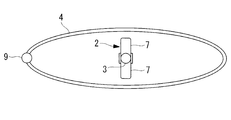
As shown in FIG. 1, theligating device 1 according to the present embodiment has an elongated flexible forceps shaft 3 having a grasping forceps (forceps) 2 at the tip, and an elongated flexible forceps having a ligation loop 4 at the tip. And a sheath 6 for accommodating these in a longitudinally movable manner.
本実施形態に係る結紮デバイス1は、図1に示されるように、先端に把持鉗子(鉗子)2を備える細長い可撓性の鉗子用シャフト3と、先端に結紮用ループ4を備える細長い可撓性のループ用シャフト5と、これらを長手方向に相対移動可能に収容するシース6とを備えている。 A
As shown in FIG. 1, the
把持鉗子2は、一方向に開閉可能に設けられた一対のジョー7を備え、図示しないワイヤによってジョー7を開閉することができるようになっている。
結紮用ループ4は、ワイヤ8の一端を巻いて結び目9により結ぶことにより自由状態で略長円形に広がる形態に形成されている。ワイヤ8の結び目9は、略長円形の結紮用ループ4の長径の端部に配置され、その位置にループ用シャフト5の先端が配置されている。 Thegrasping forceps 2 includes a pair of jaws 7 that can be opened and closed in one direction, and the jaws 7 can be opened and closed by a wire (not shown).
Theligation loop 4 is formed in a form that extends in a substantially oval shape in a free state by winding one end of the wire 8 and tying it with a knot 9. The knot 9 of the wire 8 is arranged at the end of the long diameter of the substantially oval ligation loop 4, and the tip of the loop shaft 5 is arranged at that position.
結紮用ループ4は、ワイヤ8の一端を巻いて結び目9により結ぶことにより自由状態で略長円形に広がる形態に形成されている。ワイヤ8の結び目9は、略長円形の結紮用ループ4の長径の端部に配置され、その位置にループ用シャフト5の先端が配置されている。 The
The
ループ用シャフト5は、結紮用ループ4を構成するワイヤ8を貫通させるルーメン10を備えている。ルーメン10の口径を結び目9より小さく構成することで、結び目9がルーメン10内に引き込まれないように構成されている。
The loop shaft 5 includes a lumen 10 through which the wire 8 constituting the ligation loop 4 passes. By configuring the lumen 10 to have a smaller diameter than the knot 9, the knot 9 is configured not to be drawn into the lumen 10.
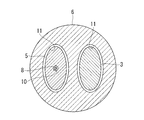
本実施形態においては、図2に示されるように、鉗子用シャフト3およびループ用シャフト5はいずれも、シース6内に配置されている部分の少なくとも一部において、略半円形の横断面を有し、シース6のルーメン11は、鉗子用シャフト3およびループ用シャフト5を組み合わせて形成される円形の横断面形状より若干大きな円形の横断面形状を有している。
すなわち、横断面円形のルーメン11を有するシース6と、鉗子用シャフト3およびループ用シャフト5の横断面形状によって、鉗子用シャフト3およびループ用シャフト5の長手方向に沿う個別の移動、すなわち相対的な移動を許容しつつ、長手軸回りの相対的な位相を拘束するように両シャフト3,5を接続する接続手段12が構成されている。 In this embodiment, as shown in FIG. 2, theforceps shaft 3 and the loop shaft 5 both have a substantially semicircular cross section in at least a part of the portion disposed in the sheath 6. The lumen 11 of the sheath 6 has a circular cross-sectional shape slightly larger than the circular cross-sectional shape formed by combining the forceps shaft 3 and the loop shaft 5.
That is, individual movements along the longitudinal direction of theforceps shaft 3 and the loop shaft 5 by the sheath 6 having the lumen 11 having a circular cross section and the cross-sectional shapes of the forceps shaft 3 and the loop shaft 5, that is, relative The connecting means 12 is configured to connect the shafts 3 and 5 so as to constrain the relative phase around the longitudinal axis while permitting smooth movement.
すなわち、横断面円形のルーメン11を有するシース6と、鉗子用シャフト3およびループ用シャフト5の横断面形状によって、鉗子用シャフト3およびループ用シャフト5の長手方向に沿う個別の移動、すなわち相対的な移動を許容しつつ、長手軸回りの相対的な位相を拘束するように両シャフト3,5を接続する接続手段12が構成されている。 In this embodiment, as shown in FIG. 2, the
That is, individual movements along the longitudinal direction of the
そして、本実施形態に係る結紮デバイス1においては、結紮用ループ4は、図1に示されるように、自由状態で、ループ用シャフト5の長手軸に対して略90°湾曲し、ループ用シャフト5の長手軸に直交する面(例えば、平面や曲面)内に概略沿って広がるように癖づけられている。なお湾曲角度は略90°に限られず、任意の角度に設定してよい。また、ループ用シャフト5の先端部近傍には、図6に示されるように、鉗子用シャフト3から結び目9が一定距離だけ離れる方向に湾曲する湾曲部が設けられているものとする。
In the ligating device 1 according to the present embodiment, the ligation loop 4 is bent approximately 90 ° with respect to the longitudinal axis of the loop shaft 5 in a free state, as shown in FIG. 5 is extended so as to extend approximately along a plane (for example, a plane or a curved surface) orthogonal to the longitudinal axis of 5. The bending angle is not limited to approximately 90 °, and may be set to an arbitrary angle. Further, as shown in FIG. 6, it is assumed that a bending portion that bends in a direction in which the knot 9 is separated from the forceps shaft 3 by a certain distance is provided in the vicinity of the distal end portion of the loop shaft 5.
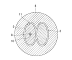
また、本実施形態においては、鉗子用シャフト3およびループ用シャフト5が、組み合わせられることによって円形の横断面形状が構成された状態では、図3に示されるように、把持鉗子2の開閉方向が、結紮用ループ4の短径方向と略平行に配されるように、両者の相対的な位相関係が設定されるようになっている。ここで、両者の位相関係は、少なくとも鉗子用シャフト3の移動方向から見た場合の把持鉗子2、とくにジョー7に対する結紮用ループ4の位相(位置関係および/または配置角度)が、結紮用ループ4による一連の結紮作業の期間中、一定であることが好ましい。
そして、このような相対的な位相関係は、略半円形の横断面を組み合わせて略円形に形成された横断面を円形のルーメン11を有するシース6に収容して拘束することにより、シース6に対してループ用シャフト5あるいは鉗子用シャフト3のいずれを長手方向に移動させても変化せず、一定に維持されるようになっている。 In this embodiment, when theforceps shaft 3 and the loop shaft 5 are combined to form a circular cross-sectional shape, the opening / closing direction of the grasping forceps 2 is changed as shown in FIG. The relative phase relationship between the two is set so as to be substantially parallel to the minor axis direction of the ligation loop 4. Here, the phase relationship between them is that the phase (positional relationship and / or arrangement angle) of the ligation loop 4 with respect to the grasping forceps 2, particularly the jaw 7 when viewed from the direction of movement of the forceps shaft 3 at least. 4 is preferably constant during the series of ligation operations according to 4.
Such a relative phase relationship is obtained by combining the substantially semicircular cross section into asheath 6 having a circular lumen 11 and constraining the cross section formed in a substantially circular shape to the sheath 6. On the other hand, even if either the loop shaft 5 or the forceps shaft 3 is moved in the longitudinal direction, it does not change and is kept constant.
そして、このような相対的な位相関係は、略半円形の横断面を組み合わせて略円形に形成された横断面を円形のルーメン11を有するシース6に収容して拘束することにより、シース6に対してループ用シャフト5あるいは鉗子用シャフト3のいずれを長手方向に移動させても変化せず、一定に維持されるようになっている。 In this embodiment, when the
Such a relative phase relationship is obtained by combining the substantially semicircular cross section into a
このように構成された本実施形態に係る結紮デバイス1の作用について以下に説明する。
本実施形態に係る結紮デバイス1を用いて左心耳Aの結紮処置を行うには、まず、把持鉗子2および結紮用ループ4をシース6のルーメン11内に引っ込めた状態に収容しておく。そして、剣状突起下部から体表組織および心膜を貫通して心嚢内にシース6の先端開口を配置した状態で、図1に示されるように、ループ用シャフト5および鉗子用シャフト3の各先端部分をルーメン11から突出させる。このとき、ループ用シャフト5に支持された結紮用ループ4は長手軸に対しほぼ垂直な面において楕円形状に拡がるよう癖付けられているので、図3に示されるように鉗子用シャフト3を中心にして囲んだ状態となる。ここで、把持鉗子2のジョー7は閉じた状態であり、結紮用ループ4内を自由に前進または後退することができる。次に、内視鏡観察下において、図4に示されるように、鉗子用シャフト3をシース6の先端から押し出して左心耳Aに近接させる。 The operation of theligating device 1 according to this embodiment configured as described above will be described below.
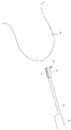
In order to perform the ligation treatment of the left atrial appendage A using theligation device 1 according to the present embodiment, first, the grasping forceps 2 and the ligation loop 4 are accommodated in the lumen 11 of the sheath 6. Then, in the state where the distal end opening of the sheath 6 is disposed in the pericardium through the body surface tissue and pericardium from the lower part of the xiphoid process, each of the loop shaft 5 and the forceps shaft 3 is arranged as shown in FIG. The tip portion protrudes from the lumen 11. At this time, since the ligation loop 4 supported by the loop shaft 5 is brazed so as to expand in an elliptical shape in a plane substantially perpendicular to the longitudinal axis, the forceps shaft 3 is centered as shown in FIG. Will be enclosed. Here, the jaw 7 of the grasping forceps 2 is in a closed state, and can be freely advanced or retracted in the ligation loop 4. Next, under endoscopic observation, as shown in FIG. 4, the forceps shaft 3 is pushed out from the distal end of the sheath 6 and brought close to the left atrial appendage A.
本実施形態に係る結紮デバイス1を用いて左心耳Aの結紮処置を行うには、まず、把持鉗子2および結紮用ループ4をシース6のルーメン11内に引っ込めた状態に収容しておく。そして、剣状突起下部から体表組織および心膜を貫通して心嚢内にシース6の先端開口を配置した状態で、図1に示されるように、ループ用シャフト5および鉗子用シャフト3の各先端部分をルーメン11から突出させる。このとき、ループ用シャフト5に支持された結紮用ループ4は長手軸に対しほぼ垂直な面において楕円形状に拡がるよう癖付けられているので、図3に示されるように鉗子用シャフト3を中心にして囲んだ状態となる。ここで、把持鉗子2のジョー7は閉じた状態であり、結紮用ループ4内を自由に前進または後退することができる。次に、内視鏡観察下において、図4に示されるように、鉗子用シャフト3をシース6の先端から押し出して左心耳Aに近接させる。 The operation of the
In order to perform the ligation treatment of the left atrial appendage A using the
この状態で、左心耳Aに近づけた把持鉗子2の一対のジョー7の開閉方向が左心耳Aの厚さ方向に一致していない場合には、体外に露出しているシース6の基端側を固定するとともに、固定されたシース6内においてループ用シャフト5および鉗子用シャフト3を一体的にシース6の長手軸回りに回転させる。これにより、把持鉗子2の開閉方向が左心耳Aの厚さ方向に一致するように、把持鉗子2の位相を調節することができる。
In this state, when the opening / closing direction of the pair of jaws 7 of the grasping forceps 2 close to the left atrial appendage A does not coincide with the thickness direction of the left atrial appendage A, the proximal end side of the sheath 6 exposed to the outside of the body And the loop shaft 5 and the forceps shaft 3 are integrally rotated around the longitudinal axis of the sheath 6 in the fixed sheath 6. Thereby, the phase of the grasping forceps 2 can be adjusted so that the opening / closing direction of the grasping forceps 2 matches the thickness direction of the left atrial appendage A.
この状態で、操作者は、鉗子用シャフト3の基端に配置されている図示しない操作部を操作することによって、把持鉗子2の一対のジョー7を開き、ジョー7の間に左心耳Aが配されるように把持鉗子2を前進させて、ジョー7を閉じることにより、図5に示されるように、把持鉗子2によって左心耳Aを厚さ方向に挟むことができる。
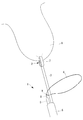
そして、ループ用シャフト5を長手方向に押すことにより、図5に示されるように、シース6の先端から結紮用ループ4を前方に押し出すことができる。 In this state, the operator opens a pair ofjaws 7 of the grasping forceps 2 by operating an operation unit (not shown) disposed at the proximal end of the forceps shaft 3, and the left atrial appendage A is located between the jaws 7. By moving the grasping forceps 2 forward and closing the jaw 7, the left atrial appendage A can be sandwiched in the thickness direction by the grasping forceps 2 as shown in FIG.
Then, by pushing theloop shaft 5 in the longitudinal direction, the ligation loop 4 can be pushed forward from the distal end of the sheath 6 as shown in FIG.
そして、ループ用シャフト5を長手方向に押すことにより、図5に示されるように、シース6の先端から結紮用ループ4を前方に押し出すことができる。 In this state, the operator opens a pair of
Then, by pushing the
この場合において、本実施形態においては、把持鉗子2と結紮用ループ4の相対的な位相が一定に維持されているので、把持鉗子2によって左心耳Aを厚さ方向に挟むと、結紮用ループ4が左心耳Aの横断面形状に一致するように左心耳Aの厚さ方向に短径、左心耳Aの幅方向に長径を一致させて配置される。
In this case, in this embodiment, since the relative phase between the grasping forceps 2 and the ligation loop 4 is maintained constant, if the left atrial appendage A is sandwiched in the thickness direction by the grasping forceps 2, the ligation loop 4 is arranged with the short diameter in the thickness direction of the left atrial appendage A and the long diameter in the width direction of the left atrial appendage A so as to match the cross-sectional shape of the left atrial appendage A.
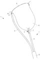
したがって、操作者は、シース6および鉗子用シャフト3に対してループ用シャフト5を押し出すように長手方向に移動させるだけで、図6に示されるように、結紮用ループ4を左心耳Aの周囲にはめ込んで行くことができる。このとき、ループ用シャフト5は、左心耳Aの幅方向の輪郭形状に倣うように湾曲させられながら前進していく。ループ用シャフト5を前進させる間、鉗子用シャフト3をループ用シャフト5に対して後退させてもよい。鉗子用シャフト3を後退させることで、対象部位である左心耳Aが結紮用ループ4に向けて扁平な形状のままジョー7を中心に引き延ばされるので、結紮用ループ4を挿入し易くなる。このように、把持鉗子2と結紮用ループ4との相対的な位相を一定に維持しつつ、接続手段12により、鉗子用シャフト3とループ用シャフト5とを長手軸方向に相対移動可能に接続したことにより、操作者による操作を簡易にすることができ、結紮処置に要する時間を短縮することができる。そして、結紮用ループ4が左心耳Aの根元まではめ込まれた状態で、結紮用ループ4を形成しているワイヤ8の基端を体外において引き出す方向に牽引することにより、結紮用ループ4を緊縮させて、左心耳Aを結紮することができる。
Therefore, the operator simply moves the ligation loop 4 around the left atrial appendage A as shown in FIG. 6 simply by moving the loop shaft 5 in the longitudinal direction so as to push it out against the sheath 6 and the forceps shaft 3. You can go inside. At this time, the loop shaft 5 advances while being curved so as to follow the contour shape of the left atrial appendage A in the width direction. While the loop shaft 5 is advanced, the forceps shaft 3 may be retracted with respect to the loop shaft 5. By retracting the forceps shaft 3, the left atrial appendage A, which is the target site, is stretched around the jaw 7 while being flat toward the ligation loop 4, so that the ligation loop 4 can be easily inserted. As described above, the forceps shaft 3 and the loop shaft 5 are connected to each other so as to be relatively movable in the longitudinal direction by the connecting means 12 while maintaining the relative phase between the grasping forceps 2 and the ligation loop 4 constant. As a result, the operation by the operator can be simplified, and the time required for the ligation treatment can be shortened. Then, in a state where the ligation loop 4 is fitted to the base of the left atrial appendage A, the base end of the wire 8 forming the ligation loop 4 is pulled in the direction to be pulled out of the body, whereby the ligation loop 4 is contracted. And the left atrial appendage A can be ligated.
すなわち、本実施形態に係る結紮デバイス1によれば、左心耳Aの厚さ方向に把持鉗子2のジョー7の開閉方向を一致させるように位相調整を1回行うだけで、結紮用ループ4についても左心耳Aの周囲にはめ込みやすい位相に調節することができ、操作を単純化して、結紮処置を容易にし、処置時間を短縮することができるという利点がある。
That is, according to the ligation device 1 according to the present embodiment, the ligation loop 4 can be obtained by performing phase adjustment only once so that the opening / closing direction of the jaw 7 of the grasping forceps 2 matches the thickness direction of the left atrial appendage A. Can be adjusted to a phase that can be easily fitted around the left atrial appendage A, and there is an advantage that the operation can be simplified, the ligation treatment can be facilitated, and the treatment time can be shortened.
なお、本実施形態においては、横断面円形のシース6のルーメン11と横断面半円形の鉗子用シャフト3およびループ用シャフト5により接続手段12を構成したが、これに代えて、図7および図8に示されるように、鉗子用シャフト3およびループ用シャフト5の横断面形状を非円形、例えば、楕円形とし、シース6のルーメン11も鉗子用シャフト3およびループ用シャフト5より若干大きな非円形の横断面形状としてもよい。これにより、ルーメン11内での鉗子用シャフト3およびループ用シャフト5の長手軸回りの回転を拘束し、把持鉗子2と結紮用ループ4の相対的な位相を一定に維持することにしてもよい。ルーメン11は、鉗子用シャフト3およびループ用シャフト5について、図7に示されるように個別に独立していてもよいし、図8に示されるように連結していてもよい。また、横断面は楕円形に限られず他の任意の非円形であればよい。
In the present embodiment, the connecting means 12 is constituted by the lumen 11 of the sheath 6 having a circular cross section, the forceps shaft 3 and the loop shaft 5 having a semicircular cross section, but instead of this, FIG. 7 and FIG. 8, the cross-sectional shape of the forceps shaft 3 and the loop shaft 5 is non-circular, for example, an ellipse, and the lumen 11 of the sheath 6 is also a non-circular shape slightly larger than the forceps shaft 3 and the loop shaft 5. It is good also as a cross-sectional shape. Thereby, rotation around the longitudinal axis of the forceps shaft 3 and the loop shaft 5 in the lumen 11 may be restricted, and the relative phase between the grasping forceps 2 and the ligation loop 4 may be maintained constant. . The lumen 11 may be individually independent of the forceps shaft 3 and the loop shaft 5 as shown in FIG. 7, or may be connected as shown in FIG. Further, the cross section is not limited to an elliptical shape, but may be any other non-circular shape.
この場合には、シース6と鉗子用シャフト3およびループ用シャフト5との長手軸回りの相対回転が拘束されるので、把持鉗子2の位相を変化させる場合にはシース6ごとその長手軸回りに回転させればよい。
In this case, since the relative rotation around the longitudinal axis between the sheath 6 and the forceps shaft 3 and the loop shaft 5 is restricted, when the phase of the grasping forceps 2 is changed, the sheath 6 and the circumference around the longitudinal axis are all changed. Rotate.
また、結紮用ループ4の長径の端部にループ用シャフト5の先端を配置する場合、鉗子用シャフト3あるいはループ用シャフト5を湾曲させなければ、結紮用ループ4の中心近傍に把持鉗子2を配置することができない。そこで、鉗子用シャフト3あるいはループ用シャフト5の少なくとも一方の先端部近傍に、他方から離れる方向に湾曲する湾曲部(図示略)を備えていてもよい。
湾曲部としては、ワイヤ等によって積極的に湾曲させるものの他、曲がり癖を付けたものでもよい。これにより、把持鉗子2によって左心耳Aの幅方向の中央を把持し、結紮用ループ4を左心耳Aの周囲にスムーズにはめ込むことができる。 Further, when the distal end of theloop shaft 5 is arranged at the end of the long diameter of the ligation loop 4, the grasping forceps 2 is placed near the center of the ligation loop 4 unless the forceps shaft 3 or the loop shaft 5 is curved. Can not be placed. Therefore, a bending portion (not shown) that bends in a direction away from the other may be provided in the vicinity of the tip portion of at least one of the forceps shaft 3 or the loop shaft 5.
The bending portion may be one that is actively bent with a wire or the like, or one that is bent. Accordingly, the center of the left atrial appendage A in the width direction can be grasped by the graspingforceps 2 and the ligation loop 4 can be smoothly fitted around the left atrial appendage A.
湾曲部としては、ワイヤ等によって積極的に湾曲させるものの他、曲がり癖を付けたものでもよい。これにより、把持鉗子2によって左心耳Aの幅方向の中央を把持し、結紮用ループ4を左心耳Aの周囲にスムーズにはめ込むことができる。 Further, when the distal end of the
The bending portion may be one that is actively bent with a wire or the like, or one that is bent. Accordingly, the center of the left atrial appendage A in the width direction can be grasped by the grasping
また、本実施形態においては、結紮用ループ4の結び目9を略長円形の結紮用ループ4の長径の端部近傍に配置したが、これに代えて、図9に示されるように、結紮用ループ4の結び目9を略長円形の結紮用ループ4の短径の端部近傍に配置してもよい。このようにすることで、鉗子用シャフト3とループ用シャフト5とを近接させても、湾曲部を設けることなく、結紮用ループ4の中心に把持鉗子2を配置することができる。
Further, in the present embodiment, the knot 9 of the ligation loop 4 is arranged in the vicinity of the end of the major diameter of the substantially oval ligation loop 4, but instead of this, as shown in FIG. The knot 9 of the loop 4 may be disposed in the vicinity of the short-diameter end of the substantially oval ligation loop 4. In this way, even if the forceps shaft 3 and the loop shaft 5 are brought close to each other, the grasping forceps 2 can be arranged at the center of the ligation loop 4 without providing a bending portion.
また、本実施形態においては、シース6と鉗子用シャフト3およびループ用シャフト5との組み合わせによって、相対的な位相変化を拘束することとしたが、これに代えて、図10あるいは図11に示されるように、接続手段12として、鉗子用シャフト3およびループ用シャフト5のいずれか一方に、長手方向に沿ってアリ溝13を設け、他方にアリ溝13の横断面と相補的な形状を有する突起14を設けることにしてもよい。
In the present embodiment, the relative phase change is constrained by the combination of the sheath 6, the forceps shaft 3, and the loop shaft 5, but instead, this is shown in FIG. 10 or FIG. As shown, the connecting means 12 is provided with a dovetail groove 13 along the longitudinal direction in one of the forceps shaft 3 and the loop shaft 5 and has a shape complementary to the transverse section of the dovetail groove 13 on the other side. Protrusions 14 may be provided.
これにより、突起14をアリ溝13内で鉗子用シャフト3あるいはループ用シャフト5の長手方向に沿って移動させることにより、両シャフト3,5の長手方向の相対移動を許容し、アリ溝13と突起14を長手方向に交差する方向に係合させることによって、両シャフト3,5の相対的な位相変化を拘束することができる。
Thus, the protrusion 14 is moved along the longitudinal direction of the forceps shaft 3 or the loop shaft 5 in the dovetail groove 13 to allow relative movement in the longitudinal direction of the shafts 3 and 5. By engaging the protrusions 14 in the direction crossing the longitudinal direction, the relative phase change of the shafts 3 and 5 can be constrained.
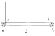
また、結紮用ループ4を構成するワイヤ8のみをループ用シャフト5の先端に設けることに代えて、図12に示されるように、ワイヤ8より剛性が高い材質からなり、結紮用ループ4の形状を維持しやすいガイド15をループ用シャフト5の先端に固定することにしてもよい。ガイド15は、長円形に形成された内周側にワイヤ8を収容する周溝16を有していて、結紮時にワイヤ8に張力がかかると、ワイヤ8が周溝16から外れて緊縮され、左心耳Aを結紮することができる。
Further, instead of providing only the wire 8 constituting the ligation loop 4 at the tip of the loop shaft 5, the shape of the ligation loop 4 is made of a material having rigidity higher than that of the wire 8 as shown in FIG. It is also possible to fix the guide 15 that is easy to maintain at the tip of the loop shaft 5. The guide 15 has a circumferential groove 16 that accommodates the wire 8 on the inner circumferential side formed in an oval shape. When tension is applied to the wire 8 during ligation, the wire 8 is released from the circumferential groove 16 and is contracted. The left atrial appendage A can be ligated.
また、本実施形態においては、鉗子2として把持鉗子を例示したが、鉗子用シャフト3の長手軸回りの方向性を有する鉗子であれば、他の鉗子であってもよい。また、結紮処置の対象部位として左心耳Aを例示したが、他の部位の結紮に使用してもよい。
Further, in the present embodiment, a grasping forceps is illustrated as the forceps 2, but other forceps may be used as long as the forceps has a direction around the longitudinal axis of the forceps shaft 3. Moreover, although the left atrial appendage A was illustrated as an object site | part of a ligation treatment, you may use it for the ligation of another site | part.
1 結紮デバイス
2 把持鉗子(鉗子)
3 鉗子用シャフト
4 結紮用ループ
5 ループ用シャフト
6 シース
7 ジョー
11 ルーメン
12 接続手段
13 アリ溝
14 突起 1ligation device 2 grasping forceps (forceps)
DESCRIPTION OFSYMBOLS 3 Forceps shaft 4 Ligation loop 5 Loop shaft 6 Sheath 7 Jaw 11 Lumen 12 Connection means 13 Dovetail 14 Projection
2 把持鉗子(鉗子)
3 鉗子用シャフト
4 結紮用ループ
5 ループ用シャフト
6 シース
7 ジョー
11 ルーメン
12 接続手段
13 アリ溝
14 突起 1
DESCRIPTION OF
Claims (9)
- 鉗子を先端に備える長尺の鉗子用シャフトと、
結紮用ループを先端に備える長尺のループ用シャフトと、
該ループ用シャフトと前記鉗子用シャフトとを長手軸方向に相対移動しつつ、少なくとも前記鉗子用シャフトについて前記相対移動方向から見たときに、前記鉗子と前記結紮用ループとの相対的な位相を一定に維持する接続手段とを備える結紮デバイス。 A long forceps shaft having a forceps at its tip;
A long loop shaft with a ligation loop at the tip;
While relatively moving the loop shaft and the forceps shaft in the longitudinal direction, the relative phase between the forceps and the ligation loop is at least when the forceps shaft is viewed from the relative movement direction. A ligation device comprising a connection means for maintaining it constant. - 前記結紮用ループが、前記ループ用シャフトの長手軸に交差する面内に広がるように癖付けられている請求項1に記載の結紮デバイス。 The ligation device according to claim 1, wherein the ligation loop is brazed so as to spread in a plane intersecting a longitudinal axis of the loop shaft.
- 前記結紮用ループが、自由状態で略長円形に形成されるとともに、長径側の端部近傍において前記ループ用シャフトによって支持されている請求項1または請求項2に記載の結紮デバイス。 The ligation device according to claim 1 or 2, wherein the ligation loop is formed in a substantially oval shape in a free state and is supported by the loop shaft in the vicinity of an end portion on the long diameter side.
- 前記結紮用ループが、自由状態で略長円形に形成されるとともに、短径側の端部近傍において前記ループ用シャフトによって支持されている請求項1または請求項2に記載の結紮デバイス。 The ligation device according to claim 1 or 2, wherein the ligation loop is formed in a substantially oval shape in a free state and is supported by the loop shaft in the vicinity of an end on the short diameter side.
- 前記鉗子が、開閉可能な一対のジョーを備え、
前記接続手段が、前記ジョーの開閉方向を、前記結紮用ループの短径に沿う方向と略平行に維持する請求項3または請求項4に記載の結紮デバイス。 The forceps includes a pair of jaws that can be opened and closed,
The ligation device according to claim 3 or 4, wherein the connection means maintains the opening / closing direction of the jaws substantially parallel to a direction along the minor axis of the ligation loop. - 前記ループ用シャフトまたは前記鉗子用シャフトの少なくとも一方の先端部近傍に、他方から離れる方向に湾曲させる湾曲部を備える請求項5に記載の結紮デバイス。 The ligating device according to claim 5, further comprising a bending portion that bends in a direction away from the other in the vicinity of the tip portion of at least one of the loop shaft or the forceps shaft.
- 前記接続手段が、前記ループ用シャフトおよび前記鉗子用シャフトを長手方向に個別に移動可能に挿入させるルーメンを有するシースを備え、
前記ループ用シャフトおよび前記鉗子用シャフトが、非円形の横断面形状の外周面を有し、
前記ルーメンが、前記ループ用シャフトおよび前記鉗子用シャフトをそれらの長手軸回りの回転を係止する横断面形状を有する請求項1から請求項6のいずれかに記載の結紮デバイス。 The connection means includes a sheath having a lumen for inserting the loop shaft and the forceps shaft individually movably in the longitudinal direction;
The loop shaft and the forceps shaft have a non-circular cross-sectional outer peripheral surface,
The ligation device according to any one of claims 1 to 6, wherein the lumen has a cross-sectional shape that locks the rotation of the loop shaft and the forceps shaft around their longitudinal axes. - 前記接続手段が、前記ループ用シャフトおよび前記鉗子用シャフトを長手方向に個別に移動可能に挿入させるルーメンを有するシースを備え、
前記ルーメンが、円形の横断面形状を有し、
前記ループ用シャフトおよび前記鉗子用シャフトが、相互に組み合わせられることにより前記ルーメンより若干小さい円形の横断面形状を構成する横断面形状をそれぞれ有する請求項1から請求項6のいずれかに記載の結紮デバイス。 The connection means includes a sheath having a lumen for inserting the loop shaft and the forceps shaft individually movably in the longitudinal direction;
The lumen has a circular cross-sectional shape;
The ligation according to any one of claims 1 to 6, wherein the loop shaft and the forceps shaft have a cross-sectional shape that forms a circular cross-sectional shape slightly smaller than the lumen by being combined with each other. device. - 前記接続手段が、前記ループ用シャフトおよび前記鉗子用シャフトの一方の外周面の長手方向に沿って設けられたアリ溝と、他方の外周面に前記アリ溝の長手方向に移動可能かつ脱落不可に収容される突起とを備える請求項1から請求項6のいずれかに記載の結紮デバイス。 The connecting means is movable along the longitudinal direction of one outer peripheral surface of the shaft for loop and the shaft for forceps, and movable in the longitudinal direction of the dovetail groove on the other outer peripheral surface, and cannot be dropped off. The ligation device according to any one of claims 1 to 6, further comprising a protrusion to be accommodated.
Priority Applications (2)
| Application Number | Priority Date | Filing Date | Title |
|---|---|---|---|
| PCT/JP2015/086135 WO2017109923A1 (en) | 2015-12-24 | 2015-12-24 | Ligation device |
| JP2017557608A JPWO2017109923A1 (en) | 2015-12-24 | 2015-12-24 | Ligation device |
Applications Claiming Priority (1)
| Application Number | Priority Date | Filing Date | Title |
|---|---|---|---|
| PCT/JP2015/086135 WO2017109923A1 (en) | 2015-12-24 | 2015-12-24 | Ligation device |
Publications (1)
| Publication Number | Publication Date |
|---|---|
| WO2017109923A1 true WO2017109923A1 (en) | 2017-06-29 |
Family
ID=59089797
Family Applications (1)
| Application Number | Title | Priority Date | Filing Date |
|---|---|---|---|
| PCT/JP2015/086135 WO2017109923A1 (en) | 2015-12-24 | 2015-12-24 | Ligation device |
Country Status (2)
| Country | Link |
|---|---|
| JP (1) | JPWO2017109923A1 (en) |
| WO (1) | WO2017109923A1 (en) |
Cited By (4)
| Publication number | Priority date | Publication date | Assignee | Title |
|---|---|---|---|---|
| US10799241B2 (en) | 2009-04-01 | 2020-10-13 | Sentreheart Llc | Tissue ligation devices and controls therefor |
| US10966725B2 (en) | 2007-03-30 | 2021-04-06 | Sentreheart Llc | Devices and systems for closing the left atrial appendage |
| US11224435B2 (en) | 2016-09-23 | 2022-01-18 | Sentreheart Llc | Devices and Methods for left atrial appendage closure |
| US11844526B2 (en) | 2018-03-27 | 2023-12-19 | Atricure, Inc. | Devices and methods for left atrial appendage closure |
Citations (7)
| Publication number | Priority date | Publication date | Assignee | Title |
|---|---|---|---|---|
| JPH1085230A (en) * | 1996-09-12 | 1998-04-07 | Fuji Photo Optical Co Ltd | High frequency treatment apparatus |
| JPH11226024A (en) * | 1998-02-17 | 1999-08-24 | Olympus Optical Co Ltd | Treating implement for endoscope |
| JP2000037390A (en) * | 1998-07-22 | 2000-02-08 | Olympus Optical Co Ltd | Endoscopic therapeutic instrument |
| JP2002051974A (en) * | 2000-08-14 | 2002-02-19 | Fuji Photo Optical Co Ltd | Endoscope manipulator |
| WO2007111670A1 (en) * | 2006-03-22 | 2007-10-04 | Boston Scientific Limited | Endoscope working channel with multiple functionality |
| US20120226287A1 (en) * | 2011-03-04 | 2012-09-06 | Mohammed Abdul Qadeer | Endoscopic devices for tissue removal or repair and associated methods |
| US20130172828A1 (en) * | 2011-12-28 | 2013-07-04 | Gary S. Kappel | Endoscopic guide wire track |
Family Cites Families (2)
| Publication number | Priority date | Publication date | Assignee | Title |
|---|---|---|---|---|
| JP4347584B2 (en) * | 2003-03-05 | 2009-10-21 | オリンパス株式会社 | Medical ligature |
| US20080294175A1 (en) * | 2007-05-21 | 2008-11-27 | Epitek, Inc. | Left atrial appendage closure |
-
2015
- 2015-12-24 WO PCT/JP2015/086135 patent/WO2017109923A1/en active Application Filing
- 2015-12-24 JP JP2017557608A patent/JPWO2017109923A1/en active Pending
Patent Citations (7)
| Publication number | Priority date | Publication date | Assignee | Title |
|---|---|---|---|---|
| JPH1085230A (en) * | 1996-09-12 | 1998-04-07 | Fuji Photo Optical Co Ltd | High frequency treatment apparatus |
| JPH11226024A (en) * | 1998-02-17 | 1999-08-24 | Olympus Optical Co Ltd | Treating implement for endoscope |
| JP2000037390A (en) * | 1998-07-22 | 2000-02-08 | Olympus Optical Co Ltd | Endoscopic therapeutic instrument |
| JP2002051974A (en) * | 2000-08-14 | 2002-02-19 | Fuji Photo Optical Co Ltd | Endoscope manipulator |
| WO2007111670A1 (en) * | 2006-03-22 | 2007-10-04 | Boston Scientific Limited | Endoscope working channel with multiple functionality |
| US20120226287A1 (en) * | 2011-03-04 | 2012-09-06 | Mohammed Abdul Qadeer | Endoscopic devices for tissue removal or repair and associated methods |
| US20130172828A1 (en) * | 2011-12-28 | 2013-07-04 | Gary S. Kappel | Endoscopic guide wire track |
Cited By (7)
| Publication number | Priority date | Publication date | Assignee | Title |
|---|---|---|---|---|
| US10966725B2 (en) | 2007-03-30 | 2021-04-06 | Sentreheart Llc | Devices and systems for closing the left atrial appendage |
| US11020122B2 (en) | 2007-03-30 | 2021-06-01 | Sentreheart Llc | Methods for closing the left atrial appendage |
| US11826050B2 (en) | 2007-03-30 | 2023-11-28 | Atricure, Inc. | Devices, systems, and methods for closing the left atrial appendage |
| US10799241B2 (en) | 2009-04-01 | 2020-10-13 | Sentreheart Llc | Tissue ligation devices and controls therefor |
| US11950784B2 (en) | 2009-04-01 | 2024-04-09 | Atricure, Inc. | Tissue ligation devices and controls therefor |
| US11224435B2 (en) | 2016-09-23 | 2022-01-18 | Sentreheart Llc | Devices and Methods for left atrial appendage closure |
| US11844526B2 (en) | 2018-03-27 | 2023-12-19 | Atricure, Inc. | Devices and methods for left atrial appendage closure |
Also Published As
| Publication number | Publication date |
|---|---|
| JPWO2017109923A1 (en) | 2018-10-11 |
Similar Documents
| Publication | Publication Date | Title |
|---|---|---|
| JP7392062B2 (en) | medical insertion device | |
| CN106659538B (en) | The clamping with mechanical dominance of robot control | |
| CN106572889B (en) | The clamping with mechanical dominance of robot control | |
| JP2022516478A (en) | Extraction basket | |
| JP6332998B2 (en) | Atrial ligation instrument | |
| WO2014156352A1 (en) | Outer sleeve tube and treatment tool | |
| JP6273298B2 (en) | Operable medical device | |
| US20160317155A1 (en) | Atrial-appendage ligation treatment tool and atrial-appendage ligation system | |
| JP6270847B2 (en) | Suture device | |
| WO2017109923A1 (en) | Ligation device | |
| JP2009247888A (en) | Medical treatment system | |
| JP5784856B2 (en) | Suture device | |
| JP2009112538A (en) | Treatment instrument for endoscope | |
| WO2017216835A1 (en) | Medical device | |
| JP6045755B2 (en) | Suture needle holder and endoscope system | |
| JP2009183690A (en) | Operative appliance for endoscope | |
| US10376283B2 (en) | Medical port | |
| JP6184639B2 (en) | Suture device | |
| JP5226905B1 (en) | Suture pushing device and suture pushing system | |
| JP2010207340A (en) | Endoscope guiding tube device | |
| WO2020110282A1 (en) | Medical treatment tool | |
| WO2021176636A1 (en) | Needle holder for endoscope, and endoscopic suturing method | |
| WO2017090190A1 (en) | Ligation device | |
| WO2021009836A1 (en) | Endoscopic treatment tool and method for using same | |
| CN220213005U (en) | Titanium clamp capable of adjusting clamping angle for endoscope |
Legal Events
| Date | Code | Title | Description |
|---|---|---|---|
| 121 | Ep: the epo has been informed by wipo that ep was designated in this application |
Ref document number: 15911361 Country of ref document: EP Kind code of ref document: A1 |
|
| ENP | Entry into the national phase |
Ref document number: 2017557608 Country of ref document: JP Kind code of ref document: A |
|
| NENP | Non-entry into the national phase |
Ref country code: DE |
|
| 122 | Ep: pct application non-entry in european phase |
Ref document number: 15911361 Country of ref document: EP Kind code of ref document: A1 |