WO2017107002A1 - Method and device for beamforming - Google Patents
Method and device for beamforming Download PDFInfo
- Publication number
- WO2017107002A1 WO2017107002A1 PCT/CN2015/098047 CN2015098047W WO2017107002A1 WO 2017107002 A1 WO2017107002 A1 WO 2017107002A1 CN 2015098047 W CN2015098047 W CN 2015098047W WO 2017107002 A1 WO2017107002 A1 WO 2017107002A1
- Authority
- WO
- WIPO (PCT)
- Prior art keywords
- layer
- precoding matrix
- layer precoding
- user equipment
- determining
- Prior art date
Links
Images


Classifications
-
- H—ELECTRICITY
- H04—ELECTRIC COMMUNICATION TECHNIQUE
- H04B—TRANSMISSION
- H04B7/00—Radio transmission systems, i.e. using radiation field
- H04B7/02—Diversity systems; Multi-antenna system, i.e. transmission or reception using multiple antennas
- H04B7/04—Diversity systems; Multi-antenna system, i.e. transmission or reception using multiple antennas using two or more spaced independent antennas
- H04B7/0413—MIMO systems
- H04B7/0456—Selection of precoding matrices or codebooks, e.g. using matrices antenna weighting
- H04B7/046—Selection of precoding matrices or codebooks, e.g. using matrices antenna weighting taking physical layer constraints into account
- H04B7/0465—Selection of precoding matrices or codebooks, e.g. using matrices antenna weighting taking physical layer constraints into account taking power constraints at power amplifier or emission constraints, e.g. constant modulus, into account
-
- H—ELECTRICITY
- H04—ELECTRIC COMMUNICATION TECHNIQUE
- H04B—TRANSMISSION
- H04B7/00—Radio transmission systems, i.e. using radiation field
- H04B7/02—Diversity systems; Multi-antenna system, i.e. transmission or reception using multiple antennas
- H04B7/04—Diversity systems; Multi-antenna system, i.e. transmission or reception using multiple antennas using two or more spaced independent antennas
- H04B7/0413—MIMO systems
- H04B7/0456—Selection of precoding matrices or codebooks, e.g. using matrices antenna weighting
-
- H—ELECTRICITY
- H04—ELECTRIC COMMUNICATION TECHNIQUE
- H04B—TRANSMISSION
- H04B17/00—Monitoring; Testing
- H04B17/30—Monitoring; Testing of propagation channels
- H04B17/309—Measuring or estimating channel quality parameters
-
- H—ELECTRICITY
- H04—ELECTRIC COMMUNICATION TECHNIQUE
- H04B—TRANSMISSION
- H04B7/00—Radio transmission systems, i.e. using radiation field
- H04B7/02—Diversity systems; Multi-antenna system, i.e. transmission or reception using multiple antennas
- H04B7/04—Diversity systems; Multi-antenna system, i.e. transmission or reception using multiple antennas using two or more spaced independent antennas
- H04B7/06—Diversity systems; Multi-antenna system, i.e. transmission or reception using multiple antennas using two or more spaced independent antennas at the transmitting station
- H04B7/0613—Diversity systems; Multi-antenna system, i.e. transmission or reception using multiple antennas using two or more spaced independent antennas at the transmitting station using simultaneous transmission
- H04B7/0615—Diversity systems; Multi-antenna system, i.e. transmission or reception using multiple antennas using two or more spaced independent antennas at the transmitting station using simultaneous transmission of weighted versions of same signal
- H04B7/0619—Diversity systems; Multi-antenna system, i.e. transmission or reception using multiple antennas using two or more spaced independent antennas at the transmitting station using simultaneous transmission of weighted versions of same signal using feedback from receiving side
- H04B7/0636—Feedback format
- H04B7/0645—Variable feedback
- H04B7/065—Variable contents, e.g. long-term or short-short
Definitions
- the present disclosure relates to wireless communication systems, and more particularly to the precoding of data to be transmitted in a Multiple-input Multiple-output (MIMO) wireless communication system. More precisely, the present disclosure aims at providing a precoding solution for very large MIMO systems known as “Massive MIMO systems” .
- MIMO Massive Multiple-Input and Multiple-Output
- Massive MIMO systems also known as Large-Scale Antenna Systems, Very Large MIMO, Hyper MIMO, Full-Dimension MIMO and ARGOS
- a base station is equipped with a very large number of antennas (e.g., hundreds or thousands) that are operated fully coherently and adaptively according to a multi-user MIMO scheme.
- inter-cell interference (ICI) and intra-cell interferences degrades the performance of massive MIMO system.
- ICI inter-cell interference
- the reduction of inter-cell interference (ICI) can be achieved by using properly configured precoders at the transmitter side (i.e. at the side of at least one base station) , in other words by choosing carefully beamforming vectors, or precoding weights, before the transmission of the signal to multiple users.
- the coordinated beamforming requires only a modest amount of signaling overhead and, for the sake of implementation, is classically proposed to improve system performance.
- each evolved Node B consists of two layers: on the one hand a first precoder, called a “cell-layer precoder” in the following of the disclosure, and a second precoder, called a “user-layer precoder” on the other hand.
- the user-layer precoder supports data transmission to the active user terminal (UEs) by exploiting the knowledge of the time-variant channel state information (CSI) .
- CSI channel state information
- the cell-layer precoder exploits the remaining spatial degree of freedom for mitigating the ICI by relying only on the knowledge of the long-term variant channel state information (CSI) .
- the cell-layer precoder of existing hierarchical-structure coordinated beamforming (CBF) schemes is adjusted to reduce Inter-Cell Interference with low complexity
- the user-layer precoder of the prior art is settled as ZF precoder, and considers power allocation issue in precoding, which may result in more intra-cell interference.
- the present disclosure proposes a method for transmitting a signal carrying data from a network equipment to a user equipment in a multiple input-multiple output (MIMO) communication system, said method optimizing the beamforming approach for the precoding scheme.
- MIMO multiple input-multiple output
- the method comprises applying a double-layer coordinated beamforming of the data prior to their transmission to the user equipment; the double-layer coordinated beamforming comprising:
- Such determining of the second layer precoding matrix is optimized by using a predetermined signal-to-interference-plus-noise ratio of the signal, and/or a predetermined power value associated with a single antenna of the user equipment, as optimization parameters.
- the present disclosure thus relies on a novel and inventive approach for beamforming by proposing a double layer coordinated beamforming minimizing the total power consumption of the considered network equipment (corresponding to an evolve node B or more generally a base station BS) , while guaranteeing the required data rate of each User Equipment and satisfying the power constraint of single antenna.
- the present disclosure permits essentially to enhance the coordinated beamforming of the prior art by adding some constraints during the optimization of the second layer precoding.
- first layer precoding is called “cell-layer precoding” whereas “second layer precoding” is called “user-layer precoding” .
- the cell-layer precoding is adjusted to reduce the Inter-cell Interference
- the cell-layer precoding obtained by the network equipment according to the present disclosure is not use to settle the user-layer precoding as a ZF precoder.
- the provided cell-layer precoding is used in combination with the value of the targeted signal-to interference-plus-noise ratio and/or with the power of the single antenna of a user equipment depending on the considered network equipment, for optimising the user-layer precoding.
- At least one constraint is additionally directly taken into account as a parameter for obtaining at least one user-layer precoding vector of second layer precoding matrix called user-layer precoding matrix in the following.
- the proposed scheme significantly increases the signal-to-interference-plus-noise ratio of cell-edge user equipment and reduces the system energy efficiency with low signalling overhead compared with the techniques of the prior art corresponding to the ZF and cluster coordinated multi-point (CoMP) schemes.
- the real-time channel state information is obtained at each time slot.
- the determining of the second layer precoding matrix is iterative until convergence and comprises for each iteration:
- the optimizing implements an iterative algorithm based on the use of two Lagrange multipliers, which are respectively optimized using on the one hand the predetermined signal-to-interference-plus-noise ratio, and on the other hand the predetermined power value.
- this embodiment is based on the application of two constraints for optimizing two distinct Lagrange multipliers permitting to obtain an associated optimal user-layer precoding vector.
- the value of the first Lagrange multiplier associated with the second layer precoding is determined by using a second layer precoding sub-gradient projection.
- the present disclosure further proposes a network equipment for transmitting a signal carrying data to a user equipment in a multiple-input multiple-output communication system, the network equipment being adapted to perform a double-layer coordinated beamforming of the data prior to their transmission to the user equipment; the network equipment comprising:
- -a receiver connected to a plurality of antennas, and configured to receive a first layer precoding matrix obtained from long-term channel state information between the user equipment and the network equipment, and
- -a precoding module connected to the receiver, and configured to determine a second layer precoding matrix obtained from the first layer precoding matrix and from real-time channel state information between the user equipment and the network equipment,
- -a double-layer coordinated beamforming module connected to the receiver and to the precoding module, configured to combine the first layer precoding matrix and the second layer precoding matrix.
- the double-layer coordinated beamforming module determining the second layer precoding matrix, is optimized by using a predetermined signal-to-interference-plus-noise ratio of the signal, and/or a predetermined power value associated with a single antenna of the user equipment, as optimization parameters.
- Such a network equipment corresponding to an evolved Node B or more generally a base station is particularly adapted to implement the method for transmitting a signal carrying data from a network equipment to a user equipment in a multiple-input multiple-output communication system as described above.
- Such a network equipment could of course comprise the different characteristics pertaining to the method of for transmitting a signal carrying data from a network equipment to a user equipment in a multiple-input multiple-output communication system.
- the features and advantages of this network equipment are the same as those of the method of for transmitting a signal carrying data from a network equipment to a user equipment in a multiple-input multiple-output communication system according to the present application, and is not described in more detail.
- the disclosure further relates to a multiple-input multiple-output communication system comprising:
- central equipment configured to determine a first layer precoding matrix (F) from at least long-term channel state information between the at least one user equipment and the at least one network equipment.
- F first layer precoding matrix
- Such a user equipment is for example a mobile phone
- the central equipment is for example an evolved Node B selected among the other evolved Nodes B of a network comprising a plurality of cells.
- the central equipment comprises a module for obtaining iteratively the first layer precoding matrix, the module for obtaining comprising the following means implemented for each iteration:
- the means for determining a value for each of the two first layer precoding Lagrange multipliers for the next iteration comprises means for performing a first layer precoding sub-gradient projection obtaining simultaneously the two first layer precoding Lagrange multipliers.
- the central equipment comprises means for initializing the threshold as a mean of a lower bound and an upper bound of inter-cell interference, said upper bound being proportional to a predetermined power value Pant associated with a single antenna of said user equipment UE.
- the object of the present disclosure uses the expression of the inter-cell interference and of the signal-to-interference-plus-noise ratio to optimize the proposed double-layer coordinated beamforming.
- Such a use imposes vast overhead among the network equipments of the considered massive MIMO system.
- Setting the upper bound, of the threshold used during the obtaining of the first layer precoding, as being proportional to a predetermined power value associated with a single antenna of said user equipment permits to overcome such a vast overhead.
- the disclosure also relates to computer program comprising instruction codes for implementing the method for transmitting a signal carrying data according to present disclosure, when loaded and run on processing means of a network equipment.
- Such a computer program is a non-transitory computer-readable medium.
- aspects of the present principles can take the form of an entirely hardware embodiment, an entirely software embodiment, or an embodiment combining software and hardware aspects.
- aspects of the present principles can take the form of a computer readable storage medium. Any combination of one or more computer readable storage medium (s) may be utilized.
- - Figure 2 represents the vector transmission channel established between a network equipment and a user equipment
- - Figure 5 represents a network equipment capable of running the method of transmission of the present disclosure.
- the general principle of the present disclosure consists in a new way of beamforming a signal carrying data implemented by a network equipment prior to its transmission to a user equipment, by applying a double-layer coordinated beamforming whose second layer is optimized, in a network equipment associated with a cell, according to the present disclosure by taking into account the result provided by the first layer and by taking into account at least one constraint among a predetermined signal-to-interference-plus-noise ratio of said signal, and/or a predetermined power value associated with a single antenna of a user equipment.
- FIG. 1 The application environment of the transmitting method according to the present disclosure is illustrated by figure 1. More precisely, a multi-user system is considered in a multi-cell scenario.
- each cell (C 1 , C 2 , C 3 ) is settled one network equipment corresponding to a base station, which is for example an evolved Node B (eNB 1 , eNB 2 , eNB 3 ) .
- a base station which is for example an evolved Node B (eNB 1 , eNB 2 , eNB 3 ) .
- K User Equipments are served by each of the L cells (for simplicity, only one User Equipment (UE) is however represented on figure 1) .
- each user equipment comprises a single antenna whose maximum power is P ant .
- T denotes a matrix transposition, transforming row vector to column vector
- diag (a) represents a diagonal matrix whose diagonal elements are the elements of vector a ,
- eNB network equipment
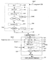
- Figure 3A illustrates the main steps of the transmitting method according to the present disclosure.
- Such a method corresponds to a double-layer precoding wherein, when considering the i-th cell among the set of L involved cell, a first layer precoding matrix F i is first provided by a first precoding layer called “Cell-layer beamforming” 3001, and a second layer precoding matrix W i is provided by a second precoding layer called “User-layer beamforming” 3002 and is used for serving the user equipments in a same cell i.
- a first layer precoding matrix F i is first provided by a first precoding layer called “Cell-layer beamforming” 3001
- a second layer precoding matrix W i is provided by a second precoding layer called “User-layer beamforming” 3002 and is used for serving the user equipments in a same cell i.
- the beamforming matrix V i is partitioned into:
- V i F i W i .
- the cell-layer precoder obtained by a central node for all eNB is used to obtain the spatial multiplexing gain for mitigating inter-cell interference (ICI) among cells. Meanwhile, the user-layer precoder supports the data transmission by exploiting the local instantaneous channel state information in each cell.
- ICI inter-cell interference
- one of the network equipments (i.e. eNB) of the massive MIMO communication system is classically chosen as a central equip (i.e. central controller) to perform the Cell-layer precoding 3001 as represented in dotted lines in figure 3B.
- said network equipment of the j-th adjacent cell estimates the corresponding spatial correlation matrix R i, jk of the communication channel between the considered k-th user equipment in the j-th cell and the i-th cell.
- said spatial correlation matrix represents long-term channel state information (long-term CSI) 3005 between each adjacent cell user interfered by the i-th cell,
- each network equipment (i.e. eNB) of the scheme according to the present disclosure only need to sens spatial correlation matrices of User equipments to the central node, which significantly reduces channel state information signalling overhead.
- the corresponding spatial correlation matrices R i, jk of channel vectors change slower than the real-time channel state information (CSI) .
- CSI channel state information
- said central equipment comprises a module for obtaining iteratively first layer precoding matrices for each involved eNB.
- said module for obtaining comprising the following means implemented for each iteration:
- n the number of iterations
- n the number of iterations
- two threshold values corresponding to two threshold bounds and used for ending the processing
- Such initialization of the obtaining of the cell-layer beamforming matrix according to the present disclosure is used to limit the overhead among eNBs managed by said central equipment when mitigating the inter-cell interference of each eNB with the cell-layer precoding.
- the “effective channel” of each cell is nearly orthogonal, which can be denoted as
- the cell layer precoder is obtained by solving the following problem as implemented by the obtaining module of the central node:
- the epigraph form of this problem is expressed as:
- Such an epigraph form of problem with fixed ⁇ is a convex problem and a bisection method to find optimal ⁇ * of ⁇ can then be used.
- the corresponding threshold ⁇ (n) is obtained such as and determining (302) at least one eigen-vector of said first layer precoding matrix is performed.
- said at least one eigen-vector corresponds to the negative eigenvalues of the matrix
- ⁇ is a constant and satisfies K ⁇ K ⁇ M and ensures that after cell-layer precoding the eNBs still have enough degree of spatial freedom for serving a user equipment.
- the absolute difference between the two threshold bounds is computed and compared (306) to a tolerable error ⁇ .
- the central node After obtaining said cell-layer precoding matrix F i with with D i the degree of spatial freedom for the it-th cell, the central node sends it to the i-th eNB, which receives (31) it can then obtain (321) the matrix as an effective channel where H i is a real time channel state information sends (3006) by each user equipment in the i-th cell at each time slot.
- an initialisation (320) is performed by said network equipment eNB i .
- ⁇ ik is the SINR value for the considered k-th user equipment
- At least one vector associated with said second layer precoding matrix is obtained (323) as following:
- ⁇ i [ ⁇ i, 1 , ⁇ i, 2 , ..., ⁇ i, K ] T and where ⁇ 2 is the power of additive white Gaussian noise, cell interference from the j-th eNB to the k-th user equipment in the i-th cell such that as well as the elements of the matrix T i ⁇ C K ⁇ K are given by :
- the user-layer precoding matrix and power allocation scheme is obtained as following: else p the number of iteration is incremented (326) and the steps (321, 322, 323, 324) of the determining 3002 of a second layer precoding matrix are reiterated until convergence (325) .
- the scheme proposed according to the present disclosure can minimize the total transmit power across all eNBs, which namely improves the system energy efficiency while guaranteeing the targeted SINR of each user equipment. Moreover, the power constraint of single antenna is considered, which improves the efficiency of power amplifier of each user equipment.
- Figure 4A to 4C represent a comparison between the results obtained according to the present disclosure and the results obtained using the prior art techniques.
- figure 4A represents the average signal-to-interference-plus-noise ratio (SINR) of a user equipment as a function of an increasing number of transmit antennas per network equipment (eNB) .
- SINR signal-to-interference-plus-noise ratio
- the average downlink SINR per user equipment (UE) of the proposed scheme guarantees the target SINR (10 dB) compared with other schemes of the prior art including the cell ZF beamforming and the coordinated multipoint (CoMP) transmission.
- Figure 4B represents the downlink SINR of cell-edge User equipment, SINR of cell-edge User equipment being defined as the 5 th percentile point of a cumulative distribution function of the user equipment’s SINR.
- the cell-edge user equipment SINR obtained according to the proposed method outperforms other schemes as the cell-layer precoder mitigates the inter-cell interference.
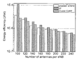
- Figure 4C represents the obtained energy efficiency according to the proposed scheme. It can be seen, that the present disclosure permits to reach an energy efficiency, which is slightly larger than the one obtained using the coordinated multipoint (CoMP) transmission. It has to be noted that in the cluster (CoMP) scheme, network equipments (eNBs) in the same cluster serve the same user equipment (UE) , thus each eNB need less power compared to the proposed scheme.
- CoMP cluster
- the cluster (CoMP) scheme needs the instantaneous channel state information (like in the present disclosure) , but also the data information of the target user equipments to be shared among the eNBs in the same cluster, which will consume overwhelming overhead resources compared to the proposed scheme, which does not require such data information.
- figure 5 illustrates the simplified structure of network equipment (eNB) implementing or being used for implementing a method for transmitting a signal as described here above.
- eNB network equipment
- a network equipment as illustrated in figure 5, comprises a memory 51 comprising a buffer memory, a processing unit 52 equipped for example with a microprocessor ⁇ P and driven by the computer program 53, implementing the method for performing for transmitting a signal according to the present disclosure.
- the code instructions of the computer program 53 are for example loaded into a RAM and then executed by the processor of the processing unit 52.
- the microprocessor of the processing unit 52 implements the steps of the method for transmitting a signal as described here above according to the computer program instructions 53.
- the network equipment comprises, in addition to the buffer memory 51, a receiver, connected to a plurality of antennas, and configured to receive a first layer precoding matrix (F) obtained from long-term channel state information between a user equipment and said network equipment, a precoding module, connected to said receiver, and configured to determine a second layer precoding matrix (W) obtained from said first layer precoding matrix and from real-time channel state information (H i ) between said user equipment and said network equipment, adouble-layer coordinated beamforming (V) module, connected to the receiver and to the precoding module, configured to combine said first layer precoding matrix (F) and said second layer precoding matrix (W) , said double-layer coordinated beamforming (V) module, determining said second layer precoding matrix (W) , being optimized by using a predetermined signal-to-interference-plus-noise ratio (SINR) of said signal, and/or a predetermined power value (Pant) associated with a single antenna of said user equipment (UE) ,
- SINR signal-to-
Abstract
The invention relates to a method for transmitting a signal carrying data in a multiple-input multiple-output (MIMO) communication system, said method comprising applying a double-layer coordinated beamforming comprising: -receiving (31) a first layer precoding matrix (F) obtained at least from long-term channel state information between said user equipment and said network equipment, and -determining (3002) a second layer precoding matrix (W) obtained from said first layer precoding matrix and from real-time channel state information (Hi) between said user equipment and said network equipment, -obtaining (33) said double-layer coordinated beamforming (V) by combining said first layer precoding matrix (F) and said second layer precoding matrix (W). According to the present disclosure, determining said second layer precoding matrix (W) is optimized by using a predetermined signal-to-interference-plus-noise ratio (SINR) of said signal, and/or a predetermined power value (Pant) associated with a single antenna of said user equipment (UE), as optimization parameters.
Description
The present disclosure relates to wireless communication systems, and more particularly to the precoding of data to be transmitted in a Multiple-input Multiple-output (MIMO) wireless communication system. More precisely, the present disclosure aims at providing a precoding solution for very large MIMO systems known as “Massive MIMO systems” .
2.Background Art
Massive Multiple-Input and Multiple-Output (MIMO) technology has attracted much attention in wireless communications, because it offers significant increases in data throughput and link range without an additional increase in bandwidth or transmit power. Both theoretical and measurement results indicate that massive MIMO is capable of significantly improving the Spectrum Efficiency, while simultaneously improving energy efficiency.
In Massive MIMO systems (also known as Large-Scale Antenna Systems, Very Large MIMO, Hyper MIMO, Full-Dimension MIMO and ARGOS) a base station is equipped with a very large number of antennas (e.g., hundreds or thousands) that are operated fully coherently and adaptively according to a multi-user MIMO scheme.
Considering such a multi-user MIMO scheme where a plurality of users are respectively located in a plurality of cells of a communication network, inter-cell interference (ICI) and intra-cell interferences degrades the performance of massive MIMO system.
The reduction of inter-cell interference (ICI) can be achieved by using properly configured precoders at the transmitter side (i.e. at the side of at least one base station) , in other words by choosing carefully beamforming vectors, or precoding weights, before the transmission of the signal to multiple users.
Among the known beamforming techniques, the coordinated beamforming (CBF) requires only a modest amount of signaling overhead and, for the sake of implementation, is classically proposed to improve system performance.
Different structures of coordinated beamforming can be implemented. In particular, a hierarchical structure of coordinated beamforming is disclosed by A. Liu in “Hierarchical interference mitigation for massive MIMO cellular networks” , IEEE Trans. Signal Process., vol 62, no. 18, pp. 4786-4797, Sep. 2014.
More precisely, according to such a structure, explicitly, each evolved Node B (eNB) consists of two layers: on the one hand a first precoder, called a “cell-layer precoder” in the following of the disclosure, and a second precoder, called a “user-layer precoder” on the other hand.
In general, as disclosed by A. Liu in “Two-stage subspace constrained precoding in massive MIMO cellular systems” , IEEE Trans. Wireless Commun., vol 14, no. 6, pp. 3271-3279, Jun. 2015, the user-layer precoder supports data transmission to the active user terminal (UEs) by exploiting the knowledge of the time-variant channel state information (CSI) . As far as the cell-layer precoder is concerns, it exploits the remaining spatial degree of freedom for mitigating the ICI by relying only on the knowledge of the long-term variant channel state information (CSI) .
Although coordinated beamforming (CBF) relying on hierarchical structure needs little signal backhaul overhead, there are two main drawbacks of the existing coordinated beamforming hierarchical-structure: on the one hand, these existing schemes of the prior art are not suitable for implementation in practical massive MIMO system. Indeed, in the existing hierarchical-structure coordinated beamforming schemes, clusters of user equipments (UEs) are formed, and user equipments (UEs) in the same cluster have the same long-term channel state information (CSI) , which is impractical.
On the other hand, although the cell-layer precoder of existing hierarchical-structure coordinated beamforming (CBF) schemes is adjusted to reduce Inter-Cell Interference with low complexity, the user-layer precoder of the prior art is settled as ZF precoder, and considers power allocation issue in precoding, which may result in more intra-cell interference.
Therefore, there is a need for an alternative precoding scheme, which overcomes the drawbacks of the above-mentioned method and can offer improved performances in terms of power consumption of all evolved Node B (eNB) .
3.Summary of the Invention
It is an object of the present disclosure to overcome disadvantages and/or make improvement over the prior art.
To that extent, the present disclosure proposes a method for transmitting a signal carrying data from a network equipment to a user equipment in a multiple input-multiple output (MIMO) communication system, said method optimizing the beamforming approach for the precoding scheme.
The method comprises applying a double-layer coordinated beamforming of the data prior to their transmission to the user equipment; the double-layer coordinated beamforming comprising:
-receiving a first layer precoding matrix obtained at least from long-term channel state information between the user equipment and the network equipment, and
-determining a second layer precoding matrix obtained from the first layer precoding matrix and from real-time channel state information between the user equipment and the network equipment,
-obtaining the double-layer coordinated beamforming by combining the first layer precoding matrix and the second layer precoding matrix,
Such determining of the second layer precoding matrix is optimized by using a predetermined signal-to-interference-plus-noise ratio of the signal, and/or a predetermined power value associated with a single antenna of the user equipment, as optimization parameters.
The present disclosure thus relies on a novel and inventive approach for beamforming by proposing a double layer coordinated beamforming minimizing the total power consumption of the considered network equipment (corresponding to an evolve node B or more generally a base station BS) , while guaranteeing the required data rate of each User Equipment and satisfying the power constraint of single antenna.
More precisely, the present disclosure permits essentially to enhance the coordinated beamforming of the prior art by adding some constraints during the optimization of the second layer precoding.
In the following, the expression “first layer precoding” is called “cell-layer precoding” whereas “second layer precoding” is called “user-layer precoding” .
On the one hand, the cell-layer precoding is adjusted to reduce the Inter-cell Interference
In comparison with the prior art the cell-layer precoding obtained by the network equipment according to the present disclosure is not use to settle the user-layer precoding as a ZF precoder.
Indeed, according to the present disclosure, the provided cell-layer precoding is used in combination with the value of the targeted signal-to interference-plus-noise ratio and/or with the power of the single antenna of a user equipment depending on the considered network equipment, for optimising the user-layer precoding.
In other words, at least one constraint is additionally directly taken into account as a parameter for obtaining at least one user-layer precoding vector of second layer precoding matrix called user-layer precoding matrix in the following.
Taking into account such at least one additional parameter certainly represents a constraint but permits to avoid the clustering of user equipments and the required transmission of data information of a target user equipment shared among the network equipments of same cluster, which consumes overwhelming overhead resources compared to the proposed coordinated beamforming scheme of the present disclosure.
As a consequence, the proposed scheme significantly increases the signal-to-interference-plus-noise ratio of cell-edge user equipment and reduces the system energy efficiency with low signalling overhead compared with the techniques of the prior art corresponding to the ZF and cluster coordinated multi-point (CoMP) schemes.
According to a particular aspect of the present disclosure, the real-time channel state information is obtained at each time slot.
In an embodiment of the present disclosure, the determining of the second layer precoding matrix is iterative until convergence and comprises for each iteration:
-with a fixed value of a first Lagrange multiplier associated with the second layer precoding matrix, using the predetermined signal-to-interference-plus-noise ratio for optimizing a second layer Lagrange multiplier associated with the second layer precoding,
-from the second layer Lagrange multiplier associated with the second layer precoding, obtaining at least one vector associated with the second layer precoding matrix,
-using the at least one vector associated with the second layer precoding matrix and the predetermined power value associated with a single antenna of the user equipment for determining, for the next iteration, a value of the first Lagrange multiplier associated with the second layer precoding.
In other words, according to the embodiments, the optimizing implements an iterative algorithm based on the use of two Lagrange multipliers, which are respectively optimized using on the one hand the predetermined signal-to-interference-plus-noise ratio, and on the other hand the predetermined power value. Thus, this embodiment is based on the application of two constraints for optimizing two distinct Lagrange multipliers permitting to obtain an associated optimal user-layer precoding vector.
According to a particular aspect of the embodiment, the value of the first Lagrange multiplier associated with the second layer precoding is determined by using a second layer precoding sub-gradient projection.
The present disclosure further proposes a network equipment for transmitting a signal carrying data to a user equipment in a multiple-input multiple-output communication system, the network equipment being adapted to perform a double-layer coordinated beamforming of the data prior to their transmission to the user equipment; the network equipment comprising:
-a receiver, connected to a plurality of antennas, and configured to receive a first layer precoding matrix obtained from long-term channel state information between the user equipment and the network equipment, and
-a precoding module, connected to the receiver, and configured to determine a second layer precoding matrix obtained from the first layer precoding matrix and from real-time channel state information between the user equipment and the network equipment,
-a double-layer coordinated beamforming module, connected to the receiver and to the precoding module, configured to combine the first layer precoding matrix and the second layer precoding matrix.
In such a network equipment, the double-layer coordinated beamforming module, determining the second layer precoding matrix, is optimized by using a predetermined signal-to-interference-plus-noise ratio of the signal, and/or a predetermined power value associated with a single antenna of the user equipment, as optimization parameters.
Such a network equipment corresponding to an evolved Node B or more generally a base station, is particularly adapted to implement the method for transmitting a signal carrying data from a network equipment to a user equipment in a multiple-input multiple-output communication system as described above.
Such a network equipment could of course comprise the different characteristics pertaining to the method of for transmitting a signal carrying data from a network equipment to a user equipment in a multiple-input multiple-output communication system. Thus, the features and advantages of this network equipment are the same as those of the method of for transmitting a signal carrying data from a network equipment to a user equipment in a multiple-input multiple-output communication system according to the present application, and is not described in more detail.
The disclosure further relates to a multiple-input multiple-output communication system comprising:
-at least one network equipment according as described above,
-at least one user equipment comprising a single antenna,
-a central equipment configured to determine a first layer precoding matrix (F) from at least long-term channel state information between the at least one user equipment and the at least one network equipment.
Such a user equipment is for example a mobile phone, and the central equipment is for example an evolved Node B selected among the other evolved Nodes B of a network comprising a plurality of cells.
More precisely, according to a particular aspect of this embodiment, the central equipment comprises a module for obtaining iteratively the first layer precoding matrix, the module for obtaining comprising the following means implemented for each iteration:
-means for determining at least one eigen-vector of the first layer precoding matrix, from the long-term channel state information and two first layer precoding Lagrange, and for determining a value for each of the two first layer precoding Lagrange for the next iteration, the means for determining being implemented until convergence,
-means for determining at least one threshold value for the next iteration, said means for determining being implemented once convergence is reached,
-means for comparing the at least one threshold value with a value representing a tolerable error.
According to a particular feature of this embodiment, the means for determining a value for each of the two first layer precoding Lagrange multipliers for the next iteration comprises means for performing a first layer precoding sub-gradient projection obtaining simultaneously the two first layer precoding Lagrange multipliers.
According to another particular feature of this embodiment, the central equipment comprises means for initializing the threshold as a mean of a lower bound and an upper bound of inter-cell interference, said upper bound being proportional to a predetermined power value Pant associated with a single antenna of said user equipment UE.
Indeed, the object of the present disclosure uses the expression of the inter-cell interference and of the signal-to-interference-plus-noise ratio to optimize the proposed double-layer coordinated beamforming. Such a use imposes vast overhead among the network equipments of the considered massive MIMO system. Setting the upper bound, of the threshold used during the obtaining of the first layer precoding, as being proportional to a predetermined power value associated with a single antenna of said user equipment permits to overcome such a vast overhead.
The disclosure also relates to computer program comprising instruction codes for implementing the method for transmitting a signal carrying data according to present disclosure, when loaded and run on processing means of a network equipment.
Such a computer program is a non-transitory computer-readable medium.
Although examples of the invention have been described hereinabove in relation with a limited number of embodiments, those skilled in the art, when reading this description, will understand that other embodiments can be imagined without leaving the scope of this invention.
In particular, while not explicitly described, the present embodiments may be employed in any combination or sub-combination.
Accordingly, aspects of the present principles can take the form of an entirely hardware embodiment, an entirely software embodiment, or an embodiment combining software and hardware aspects. Furthermore, aspects of the present principles can take the form of a computer readable storage medium. Any combination of one or more computer readable storage medium (s) may be utilized.
Other features and advantages of the invention will become apparent from the following description of non-limiting exemplary embodiments, with reference to the appended drawings, in which:
-Figure 1 represents a simplified communication system, which illustrates the principle of the invention,
-Figure 2 represents the vector transmission channel established between a network equipment and a user equipment,
-Figures 3A and 3B illustrate the steps of the method for transmitting a signal carrying data that is subject of the present invention,
-Figure 4A to 4C represent a comparison between the results obtained according to the present disclosure and the results obtained using the prior art techniques,
-Figure 5 represents a network equipment capable of running the method of transmission of the present disclosure.
5.1 General Principle
The general principle of the present disclosure consists in a new way of beamforming a signal carrying data implemented by a network equipment prior to its transmission to a user equipment, by applying a double-layer coordinated beamforming whose second layer is optimized, in a network equipment associated with a cell, according to the present disclosure by taking into account the result provided by the first layer and by taking into account at least one constraint among a predetermined signal-to-interference-plus-noise ratio of said signal, and/or a predetermined power value associated with a single antenna of a user equipment.
Various non-limiting embodiments of beamforming method, corresponding device, communication system computer program and computer-readable storage medium for beamforming are disclosed in the next sections.
This disclosure may, however, be embodied in many alternate forms and should not be construed as limited to the embodiments set forth herein.
5.2 The transmitting method
5.2.1 Application environment and main steps of the transmitting method
The application environment of the transmitting method according to the present disclosure is illustrated by figure 1. More precisely, a multi-user system is considered in a multi-cell scenario.
In the following, in such a scenario L cells are considered in the network (in figure 1, for simplicity L=3 which corresponds to cells C1, C2, and C3, but a higher number of cells can
obviously be taken into account since a massive MIMO communication system is considered in the present disclosure) .
In each cell (C1, C2, C3) is settled one network equipment corresponding to a base station, which is for example an evolved Node B (eNB1, eNB2, eNB3) .
In addition, K User Equipments (UEs) are served by each of the L cells (for simplicity, only one User Equipment (UE) is however represented on figure 1) .
More precisely, as illustrated by figure 2 representing the vector transmission channel established between a network equipment and a user equipment, it can be seen that each eNB, comprises M antennas, and is able to provide a peak power PT=MxPant.
Moreover, each user equipment (UE) comprises a single antenna whose maximum power is Pant.
In the following the general notations hereafter are used:
-the operators (.) H and tr (.) denote respectively conjugate transpose and trace,
-the operators (.) T denotes a matrix transposition, transforming row vector to column vector,
-the operator (.) + is such that 
-the operator diag (a) represents a diagonal matrix whose diagonal elements are the elements of vector a ,
-IN represents an identity matrix of size N,
-C denotes the set of all complex numbers,
-UM×N denotes the set of all M×N semi-unitary matrices, which satisfies UHU=IN,
-[A] m, n denotes the (m, n) -th entry of a matrix A,
-hi, jk∈CM×1 is a channel coefficient vector from a network equipment (eNB) of the i-th cell among the L cells (i.e. i
=1, 2, … L) to the k-th User Equipment in the j-th cell modelled as  with:
with:
- having independent identically distributed complex entries with zero mean and variance one, and
- 
is a deterministic Hermitian-symmetric positive definite matrix, where “E” means expectation operation.
Figure 3A illustrates the main steps of the transmitting method according to the present disclosure. Such a method corresponds to a double-layer precoding wherein, when considering the i-th cell among the set of L involved cell, a first layer precoding matrix Fi is first provided by a first precoding layer called “Cell-layer beamforming” 3001, and a second layer precoding matrix
Wi is provided by a second precoding layer called “User-layer beamforming” 3002 and is used for serving the user equipments in a same cell i.
In other words, for each eNB i, the beamforming matrix Vi is partitioned into:
-a cell-layer beamforming precoding matrix 3001 Fi provided by a central equipment of the considered communication system, and
-a user-layer beamforming precoding matrix W i 3002 provided by the eNB i
itself.
These two precoding matrices being then combined such as: Vi=FiWi.
The cell-layer precoder obtained by a central node for all eNB, is used to obtain the spatial multiplexing gain for mitigating inter-cell interference (ICI) among cells. Meanwhile, the user-layer precoder supports the data transmission by exploiting the local instantaneous channel state information in each cell.
Each precoding stage is detailed hereafter.
5.2.2 Cell-layer Beamforming precoding
It has to be noted that one of the network equipments (i.e. eNB) of the massive MIMO communication system is classically chosen as a central equip (i.e. central controller) to perform the Cell-layer precoding 3001 as represented in dotted lines in figure 3B.
Then, for each considered i-th cell (i.e.
i=1, 2, … L) :
-each k-th user equipment, of a j-th adjacent cell interfered by one network equipment (eNB) of the considered i-th cell, transmits in selected time slots dedicated pilot sequences to the network equipment of which it depends (i.e. a network equipment of the j-th adjacent cell) ,
-said network equipment of the j-th adjacent cell estimates the corresponding spatial correlation matrix Ri, jk of the communication channel between the considered k-th user equipment in the j-th cell and the i-th cell. In other words, said spatial correlation matrix represents long-term channel state information (long-term CSI) 3005 between each adjacent cell user interfered by the i-th cell,
-once such long-term CSI 3005 is obtained for each adjacent cell user equipment interfered by the i-th cell, the network equipments, on which these user equipment respectively depend, send (3007) the long-term CSI to the central node through X2 interface.
It has to be noted that compared to conventional CBF or joint processing schemes, each network equipment (i.e. eNB) of the scheme according to the present disclosure only need to sens spatial correlation matrices of User equipments to the central node, which significantly reduces channel state information signalling overhead.
The central node thus acquires (3007) all the corresponding spatial correlation matrices Ri, jk for
i=1, 2, … L , considering that for a considered i-th cell Ri, jk matrices are obtained for j≠i and j=1, 2, … L and for k=1, 2, … K.
It has to be noted that the corresponding spatial correlation matrices Ri, jk of channel vectors, by nature, change slower than the real-time channel state information (CSI) . Such a property, permits to the central equipment to acquire the long-term CSI and to perform the cell-layer beamforming precoding in a long timescale in comparison with the real-time CSI acquisition and the user-layer beamforming precoding, which are then implemented on a considered eNB of a i-th cell and detailed in the following.
As illustrated by figure 3B, said central equipment comprises a module for obtaining iteratively first layer precoding matrices for each involved eNB. In other words, said central equipment delivers a vector F of L first layer precoding matrices for all L cells such that: F={F1 … Fi … FL} , i.e. one matrix per cell.
More precisely, said module for obtaining comprising the following means implemented for each iteration:
-means for determining (302) at least one eigen-vector of said first layer precoding matrix, from said long-term channel state information  and two first layer precoding Lagrange multipliers (λ, μ) , and for determining (303) a value for each of said two first layer precoding Lagrange multipliers (λ, μ) for the next iteration, said means for determining being implemented until convergence (304) ,
-means for determining (305) at least one threshold value for the next iteration, said means for updating being implemented once convergence is reached,
-means for comparing (306) said at least one threshold value with a value representing a tolerable error.
Before running said module for obtaining a step of initialization (301) is implemented wherein n, the number of iterations, is set to zero (n=0) and wherein two threshold values, corresponding to two threshold bounds  and
and  used for ending the processing, are set respectively to predetermined values such as for example:
  and
and 
and satisfy 
Such initialization of the obtaining of the cell-layer beamforming matrix according to the present disclosure is used to limit the overhead among eNBs managed by said central equipment when mitigating the inter-cell interference of each eNB with the cell-layer precoding.
In other words, considering, for example, Gj, ik the cell interference from the j-th eNB to the k-th user equipment in the i-th cell, after the cell-layer precoding performed by the central node, the “effective channel” of each cell is nearly orthogonal, which can be denoted as 
To this end, the cell layer precoder is obtained by solving the following problem as implemented by the obtaining module of the central node:
According to the present disclosure, the epigraph form of this problem is expressed as:
minXτ such that  and
and  where Xj=FjFj
H∈CM×M and X ={X1, …, XK} .
where Xj=FjFj
H∈CM×M and X ={X1, …, XK} .
Such an epigraph form of problem with fixed τ is a convex problem and a bisection method to find optimal τ* of τ can then be used.
As a consequence,  and
and  are respectively a lower bound and an upper bound of
Once, the lower and upper bound are initialized as described above, the corresponding threshold τ (n) is obtained such as  and determining (302) at least one eigen-vector
 of said first layer precoding matrix is performed.
More precisely, said at least one eigen-vector  corresponds to the negative eigenvalues of the matrix
  where:
Then a value for each of said two first layer precoding Lagrange multipliers (λ, μ) is determined (303) for the next iteration by considering  and using a sub-gradient projection method with a step size θ (n) :

These two steps 302 and 303 are implemented until convergence 304 (the “Y” and “N” in figure 3B represent respectively that convergence is achieved or not) .
More precisely, if  and
and  where i
, j=1, 2, …, L, k=1, 2, … , K and e is a tolerable error, then the two
where i
, j=1, 2, …, L, k=1, 2, … , K and e is a tolerable error, then the two steps 302 and 303 converge.
When no convergence (304) is obtained the lower bound τmin is updated 3040 such that: 
Once convergence 304 is obtained, the upper bound τmax of the threshold is updated (305) such that: 
Then, the absolute difference between the two threshold bounds is computed and compared (306) to a tolerable error ρ.  the obtaining of the first layer precoding matrix
  ends, else the next iteration with n=n+1 is performed (307) by returning to the
 step 302 for determining (302) at least one eigen-vector of said first layer precoding matrix.
Said computations are performed for j=1, 2, …, L so that said central equipment delivers a vector F of L first layer precoding matrices for all L cells such that: F={F1 … Fi … Fj … FL} , i.e. one matrix per cell.
After obtaining said cell-layer precoding matrix Fi with  with Di the degree of spatial freedom for the it-th cell, the central node sends it to the i-th eNB, which receives (31) it can then obtain (321) the matrix
  as an effective channel where Hi is a real time channel state information sends (3006) by each user equipment in the i-th cell at each time slot.
Previously, to the iterative determining 3002 of a second layer precoding matrix, an initialisation (320) is performed by said network equipment eNBi. During said initialisation (320) , the number of iterations of this determining 3002 of a second layer precoding matrix, is set to zero (p=0) and all the M values  with m=1, 2, …, M, of a first Lagrange multiplier vector
  are also set to zero.
Then, considering an iteration p, with a fixed value of said first Lagrange multiplier  values
  with k=1, 2, …, K of a second optimal Lagrange multiplier
  are obtained by considering the following problem comprising two equations with two unknown values:
and 
with  where γik is the SINR value for the considered k-th user equipment and
Then, from said second layer Lagrange multiplier  associated with said second layer precoding, at least one vector
  associated with said second layer precoding matrix is obtained (323) as following:
Then, by using known relationship between uplink and downlink user-layer precoding vector for the k-th user equipment in the i-th cell is obtained as following:
with εi= [εi, 1, εi, 2, …, εi, K] T and  where σ2 is the power of additive white Gaussian noise,
  cell interference from the j-th eNB to the k-th user equipment in the i-th cell such that
  as well as the elements of the matrix Ti∈CK×Kare given by :

Then, using said at least one vector  associated with said second layer precoding matrix and said predetermined power value (Pant) associated with a single antenna of said user equipment (UE) a value of said first Lagrange multiplier associated with said second layer precoding is determined (324) for the next iteration using a subgradient projection with step size
If convergence (325) is obtained, the user-layer precoding matrix 
 and power allocation scheme is obtained as following:
  else p the number of iteration is incremented (326) and the steps (321, 322, 323, 324) of the determining 3002 of a second layer precoding matrix are reiterated until convergence (325) .
As a consequence, the scheme proposed according to the present disclosure can minimize the total transmit power across all eNBs, which namely improves the system energy efficiency while guaranteeing the targeted SINR of each user equipment. Moreover, the power constraint of single antenna is considered, which improves the efficiency of power amplifier of each user equipment.
5.2.4 Results
Figure 4A to 4C represent a comparison between the results obtained according to the present disclosure and the results obtained using the prior art techniques.
More precisely, figure 4A represents the average signal-to-interference-plus-noise ratio (SINR) of a user equipment as a function of an increasing number of transmit antennas per network equipment (eNB) .
As can be seen the average downlink SINR per user equipment (UE) of the proposed scheme guarantees the target SINR (10 dB) compared with other schemes of the prior art including the cell ZF beamforming and the coordinated multipoint (CoMP) transmission.
Figure 4B represents the downlink SINR of cell-edge User equipment, SINR of cell-edge User equipment being defined as the 5th percentile point of a cumulative distribution function of the user equipment’s SINR.
In comparison with the other two techniques of the prior art, the cell-edge user equipment SINR obtained according to the proposed method outperforms other schemes as the cell-layer precoder mitigates the inter-cell interference.
Figure 4C represents the obtained energy efficiency according to the proposed scheme. It can be seen, that the present disclosure permits to reach an energy efficiency, which is slightly larger than the one obtained using the coordinated multipoint (CoMP) transmission. It has to be noted that in the cluster (CoMP) scheme, network equipments (eNBs) in the same cluster serve the same user equipment (UE) , thus each eNB need less power compared to the proposed scheme.
However, the cluster (CoMP) scheme needs the instantaneous channel state information (like in the present disclosure) , but also the data information of the target user equipments to be shared among the eNBs in the same cluster, which will consume overwhelming overhead resources compared to the proposed scheme, which does not require such data information.
5.3 Structure of the Network Equipment
Finally, figure 5 illustrates the simplified structure of network equipment (eNB) implementing or being used for implementing a method for transmitting a signal as described here above.
A network equipment, as illustrated in figure 5, comprises a memory 51 comprising a buffer memory, a processing unit 52 equipped for example with a microprocessor μP and driven by the computer program 53, implementing the method for performing for transmitting a signal according to the present disclosure.
At initialization, the code instructions of the computer program 53 are for example loaded into a RAM and then executed by the processor of the processing unit 52. The microprocessor of
the processing unit 52 implements the steps of the method for transmitting a signal as described here above according to the computer program instructions 53.
To this end, the network equipment according to the present disclosure comprises, in addition to the buffer memory 51, a receiver, connected to a plurality of antennas, and configured to receive a first layer precoding matrix (F) obtained from long-term channel state information between a user equipment and said network equipment, a precoding module, connected to said receiver, and configured to determine a second layer precoding matrix (W) obtained from said first layer precoding matrix and from real-time channel state information (Hi) between said user equipment and said network equipment, adouble-layer coordinated beamforming (V) module, connected to the receiver and to the precoding module, configured to combine said first layer precoding matrix (F) and said second layer precoding matrix (W) , said double-layer coordinated beamforming (V) module, determining said second layer precoding matrix (W) , being optimized by using a predetermined signal-to-interference-plus-noise ratio (SINR) of said signal, and/or a predetermined power value (Pant) associated with a single antenna of said user equipment (UE) , as optimization parameters.
These means are driven by the microprocessor of the processing unit 52.
Claims (10)
- A method for transmitting a signal carrying data from a network equipment (eNB) to a user equipment (UE) in a multiple-input multiple-output (MIMO) communication system,said method comprising applying a double-layer coordinated beamforming of said data prior to their transmission to said user equipment; said double-layer coordinated beamforming (V) comprising:-receiving (31) a first layer precoding matrix (F) obtained at least from long-term channel state information between said user equipment and said network equipment, and-determining (3002) a second layer precoding matrix (W) obtained from said first layer precoding matrix and from real-time channel state information (Hi) between said user equipment and said network equipment,-obtaining (33) said double-layer coordinated beamforming (V) by combining said first layer precoding matrix (F) and said second layer precoding matrix (W) ,wherein determining said second layer precoding matrix (W) is optimized by using a predetermined signal-to-interference-plus-noise ratio (SINR) of said signal, and/or a predetermined power value (Pant) associated with a single antenna of said user equipment (UE) , as optimization parameters.
- The method according to claim 1, wherein said real-time channel state information (Hi) is obtained at each time slot.
- The method according to claim 1, wherein determining said second layer precoding matrix is iterative until convergence and comprises for each iteration:-with a fixed value of a first Lagrange multiplier (q) associated with said second layer precoding matrix, using said predetermined signal-to-interference-plus-noise ratio (SINR) for optimizing (322) a second layer Lagrange multiplier (v) associated with said second layer precoding,-from said second layer Lagrange multiplier (v) associated with said second layer precoding, obtaining (323) at least one vectorassociated with said second layer precoding matrix,
 -using said at least one vectorassociated with said second layer precoding matrix and said predetermined power value (Pant) associated with a single antenna of said user equipment (UE) for determining (324) , for the next iteration, a value of said first Lagrange multiplier (q) associated with said second layer precoding.
- The method according to claim 3, wherein said value of said first Lagrange multiplier (q) associated with said second layer precoding matrix is determined by using a second layer precoding sub-gradient projection.
- Network equipment for transmitting a signal carrying data to a user equipment (UE) in a multiple input-multiple output (MIMO) communication system,said network equipment being adapted to perform a double-layer coordinated beamforming of said data prior to their transmission to said user equipment; said network equipment comprising:-a receiver, connected to a plurality of antennas, and configured to receive a first layer precoding matrix (F) obtained from long-term channel state information between said user equipment and said network equipment, and-a precoding module, connected to said receiver, and configured to determine a second layer precoding matrix (W) obtained from said first layer precoding matrix and from real-time channel state information (Hi) between said user equipment and said network equipment,-a double-layer coordinated beamforming (V) module, connected to the receiver and to the precoding module, configured to combine said first layer precoding matrix (F) and said second layer precoding matrix (W) ,wherein said double-layer coordinated beamforming (V) module, determining said second layer precoding matrix (W) , is optimized by using a predetermined signal-to-interference-plus-noise ratio (SINR) of said signal, and/or a predetermined power value (Pant) associated with a single antenna of said user equipment (UE) , as optimization parameters.
- A multiple input-multiple output (MIMO) communication system comprising:-at least one network equipment according to claim 5,-at least one user equipment comprising a single antenna,-a central equipment configured to determine a first layer precoding matrix (F) from at least long-term channel state information between said at least one user equipment and said at least one network equipment.
- The multiple input-multiple output (MIMO) communication system according to claim 6, wherein said central equipment comprises a module for obtaining iteratively said first layer precoding matrix, said module for obtaining comprising the following means implemented for each iteration:-means for determining (302) at least one eigen-vector of said first layer precoding matrix, from said long-term channel state informationand two first layer precoding Lagrange multipliers (λ, μ) , and for determining (303) a value for each of said two first layer precoding Lagrange multipliers (λ, μ) for the next iteration, said means for determining being implemented until convergence (304) ,
 -means for determining (305) at least one threshold value for the next iteration, said means for determining being implemented once convergence is reached,-means for comparing (306) said at least one threshold value with a value representing a tolerable error.
 - The multiple input-multiple output (MIMO) communication system according to claim 7, wherein said means for determining a value for each of said two first layer precoding Lagrange multipliers (λ, μ) for the next iteration comprises means for performing a first layer precoding sub-gradient projection obtaining simultaneously said two first layer precoding Lagrange multipliers (λ, μ) .
- The multiple input-multiple output (MIMO) communication system according to claim 7, wherein said central equipment comprises means for initializing (301) said threshold as a mean of a lower bound and an upper bound of inter-cell interference, said upper bound being proportional to a predetermined power value (Pant) associated with a single antenna of said user equipment (UE) .
- A computer program comprising instruction codes for implementing the method for transmitting a signal carrying data according to claims 1 to 4, when loaded and run on processing means of a network equipment.
Priority Applications (3)
| Application Number | Priority Date | Filing Date | Title |
|---|---|---|---|
| PCT/CN2015/098047 WO2017107002A1 (en) | 2015-12-21 | 2015-12-21 | Method and device for beamforming |
| EP16200601.9A EP3185434B8 (en) | 2015-12-21 | 2016-11-24 | Method and device for beamforming |
| US15/385,839 US10666329B2 (en) | 2015-12-21 | 2016-12-20 | Method and device for beam forming |
Applications Claiming Priority (1)
| Application Number | Priority Date | Filing Date | Title |
|---|---|---|---|
| PCT/CN2015/098047 WO2017107002A1 (en) | 2015-12-21 | 2015-12-21 | Method and device for beamforming |
Publications (1)
| Publication Number | Publication Date |
|---|---|
| WO2017107002A1 true WO2017107002A1 (en) | 2017-06-29 |
Family
ID=57394495
Family Applications (1)
| Application Number | Title | Priority Date | Filing Date |
|---|---|---|---|
| PCT/CN2015/098047 WO2017107002A1 (en) | 2015-12-21 | 2015-12-21 | Method and device for beamforming |
Country Status (3)
| Country | Link |
|---|---|
| US (1) | US10666329B2 (en) |
| EP (1) | EP3185434B8 (en) |
| WO (1) | WO2017107002A1 (en) |
Cited By (1)
| Publication number | Priority date | Publication date | Assignee | Title |
|---|---|---|---|---|
| US10666329B2 (en) * | 2015-12-21 | 2020-05-26 | Orange | Method and device for beam forming |
Families Citing this family (6)
| Publication number | Priority date | Publication date | Assignee | Title |
|---|---|---|---|---|
| CN107395259B (en) * | 2016-05-13 | 2020-04-21 | 华为技术有限公司 | Two-stage precoding method and device |
| EP3522404B1 (en) * | 2018-02-02 | 2021-04-21 | Mitsubishi Electric R&D Centre Europe B.V. | Wifi interference identification for a use in a public frequency hopping system |
| CN111181612B (en) * | 2019-12-31 | 2021-03-30 | 内蒙古大学 | Cooperative beamforming method of large-scale MIMO system |
| CN112702091B (en) * | 2020-12-22 | 2022-01-14 | 杭州电子科技大学 | Improved MAX-SINR interference alignment method in multi-user multi-antenna SWIPT |
| CN117674920A (en) * | 2022-08-12 | 2024-03-08 | 华为技术有限公司 | Uplink transmission method and device |
| CN116633399B (en) * | 2023-07-20 | 2023-11-03 | 深圳市大数据研究院 | Semantic communication waveform design method, device, equipment and storage medium |
Citations (3)
| Publication number | Priority date | Publication date | Assignee | Title |
|---|---|---|---|---|
| CN102624496A (en) * | 2011-01-30 | 2012-08-01 | 华为技术有限公司 | Precoding processing method, base station and communication system |
| CN104065448A (en) * | 2013-03-22 | 2014-09-24 | 电信科学技术研究院 | Method, system and equipment for determining pre-coding matrixes |
| WO2015094661A1 (en) * | 2013-12-18 | 2015-06-25 | Intel Corporation | User equipment and method for precoding for mimo codebook-based beamforming using an autocorrelation matrix for reduced quantization noise |
Family Cites Families (27)
| Publication number | Priority date | Publication date | Assignee | Title |
|---|---|---|---|---|
| US8363744B2 (en) * | 2001-06-10 | 2013-01-29 | Aloft Media, Llc | Method and system for robust, secure, and high-efficiency voice and packet transmission over ad-hoc, mesh, and MIMO communication networks |
| US8797950B2 (en) * | 2009-05-27 | 2014-08-05 | Texas Instruments Incorporated | Dual-layer beam forming in cellular networks |
| US8711716B2 (en) * | 2009-06-19 | 2014-04-29 | Texas Instruments Incorporated | Multiple CQI feedback for cellular networks |
| EP2454827B1 (en) * | 2009-06-19 | 2019-03-27 | BlackBerry Limited | Downlink reference signal for type ii relay |
| US8750205B2 (en) * | 2009-08-07 | 2014-06-10 | Texas Instruments Incorporated | Multiple rank CQI feedback for cellular networks |
| US9351293B2 (en) * | 2009-09-11 | 2016-05-24 | Qualcomm Incorporated | Multiple carrier indication and downlink control information interaction |
| KR101719996B1 (en) * | 2009-11-06 | 2017-03-27 | 엘지전자 주식회사 | Method of resource block (rb)bundling |
| EP2507960B1 (en) * | 2009-12-04 | 2018-06-06 | Telefonaktiebolaget LM Ericsson (publ) | Apparatus and method for channel estimation in a wireless communications system |
| US9762372B2 (en) * | 2010-06-15 | 2017-09-12 | Texas Instruments Incorporated | CSI reporting on PUSCH for carrier aggregation |
| CN103155624B (en) * | 2010-10-08 | 2019-01-22 | 黑莓有限公司 | The method and apparatus determined for channel state information |
| EP2643988B1 (en) * | 2010-11-22 | 2019-09-18 | Nokia Solutions and Networks Oy | Multi-layer beamforming with partial channel state information |
| US20120182895A1 (en) * | 2011-01-13 | 2012-07-19 | Electronics And Telecommunications Research Institute | Apparatus and method for transmitting and receiving channel state information |
| KR101806311B1 (en) * | 2011-03-04 | 2017-12-07 | 삼성전자주식회사 | Network mimo communication system of using regularized beamforing |
| WO2012119314A1 (en) * | 2011-03-10 | 2012-09-13 | 富士通株式会社 | Interference coordinating method, base station and user equipment |
| US9319118B2 (en) * | 2011-04-29 | 2016-04-19 | Yuan Zhu | Technology for CSI feedback in a MIMO communication system |
| US9160425B2 (en) * | 2011-07-01 | 2015-10-13 | Telefonaktiebolaget L M Ericsson (Publ) | Beamforming with phase compensation |
| US9137818B2 (en) * | 2011-12-14 | 2015-09-15 | Alcatel Lucent | Method and system for a reduced-complexity scheduling for a network MIMO with linear zero-forcing beamforming |
| US20130331136A1 (en) * | 2012-06-07 | 2013-12-12 | Kai Yang | Method And Apparatus For Coordinated Beamforming |
| CN103634036B (en) * | 2012-08-27 | 2017-10-27 | 华为技术有限公司 | Distributed multiple cell multi-user beam-forming method, emitter and related system |
| JP6490601B2 (en) * | 2013-03-11 | 2019-03-27 | エルジー エレクトロニクス インコーポレイティド | Method and apparatus for reporting channel state information in a wireless communication system |
| US9590744B2 (en) * | 2013-05-06 | 2017-03-07 | Alcatel Lucent | Method and apparatus for beamforming |
| EP2997688B1 (en) * | 2013-05-16 | 2018-08-08 | Telefonaktiebolaget LM Ericsson (publ) | Method and apparatus for rank override |
| US9450657B2 (en) * | 2013-08-28 | 2016-09-20 | Nec Corporation | Low-complexity precoder design for large-scale MIMO communication systems |
| EP3043489B1 (en) * | 2013-09-03 | 2022-03-02 | Sony Group Corporation | Communication control apparatus, communication control method and terminal apparatus |
| CN103905105B (en) * | 2014-02-19 | 2017-10-03 | 大唐移动通信设备有限公司 | A kind of dual-stream beamforming method and apparatus |
| US10263670B2 (en) * | 2016-07-21 | 2019-04-16 | NxGen Parners IP, LLC | System and method for reducing pilot signal contamination using orthogonal pilot signals |
| WO2017107002A1 (en) * | 2015-12-21 | 2017-06-29 | Orange | Method and device for beamforming |
-
2015
- 2015-12-21 WO PCT/CN2015/098047 patent/WO2017107002A1/en active Application Filing
-
2016
- 2016-11-24 EP EP16200601.9A patent/EP3185434B8/en active Active
- 2016-12-20 US US15/385,839 patent/US10666329B2/en active Active
Patent Citations (3)
| Publication number | Priority date | Publication date | Assignee | Title |
|---|---|---|---|---|
| CN102624496A (en) * | 2011-01-30 | 2012-08-01 | 华为技术有限公司 | Precoding processing method, base station and communication system |
| CN104065448A (en) * | 2013-03-22 | 2014-09-24 | 电信科学技术研究院 | Method, system and equipment for determining pre-coding matrixes |
| WO2015094661A1 (en) * | 2013-12-18 | 2015-06-25 | Intel Corporation | User equipment and method for precoding for mimo codebook-based beamforming using an autocorrelation matrix for reduced quantization noise |
Non-Patent Citations (1)
| Title |
|---|
| ROYA DOOSTNEJAD.: "Precoding and Beamforming for Multi-Input Multi-Output Downlink Channels", A THESIS SUBMITTED IN CONFORMITY WITH THE REQUIREMENTS FOR THE DEGREE OF DOCTOR OF PHILOSOPHY, 31 December 2005 (2005-12-31), XP055395488 * |
Cited By (1)
| Publication number | Priority date | Publication date | Assignee | Title |
|---|---|---|---|---|
| US10666329B2 (en) * | 2015-12-21 | 2020-05-26 | Orange | Method and device for beam forming |
Also Published As
| Publication number | Publication date |
|---|---|
| US20170180021A1 (en) | 2017-06-22 |
| US10666329B2 (en) | 2020-05-26 |
| EP3185434B8 (en) | 2020-08-05 |
| EP3185434B1 (en) | 2020-05-27 |
| EP3185434A1 (en) | 2017-06-28 |
Similar Documents
| Publication | Publication Date | Title |
|---|---|---|
| Nguyen et al. | On the spectral and energy efficiencies of full-duplex cell-free massive MIMO | |
| US10567066B2 (en) | Apparatus and method for performing precoding in wireless communication system using massive antenna | |
| US10666329B2 (en) | Method and device for beam forming | |
| US10250309B2 (en) | System and method for downlink channel estimation in massive multiple-input-multiple-output (MIMO) | |
| Ammar et al. | Downlink resource allocation in multiuser cell-free MIMO networks with user-centric clustering | |
| CN105723627B (en) | Method and apparatus for multiresolution precoding matrix indicators feedback | |
| Mosleh et al. | Proportional-fair resource allocation for coordinated multi-point transmission in LTE-advanced | |
| Lan et al. | Considerations on downlink non-orthogonal multiple access (NOMA) combined with closed-loop SU-MIMO | |
| US8797959B2 (en) | System and method for transceiver design | |
| KR20120054028A (en) | Apparatus and method for generating codebook in wireless communication system | |
| CN107809795B (en) | Anti-interference method based on time reversal in D2D heterogeneous wireless communication network | |
| KR101997455B1 (en) | Method for coordinating interference in an uplink interference channel for a terminal in a wireless communication system | |
| CN107579762B (en) | Multi-cell cooperative precoding method based on quantification and channel information statistics | |
| Liu et al. | New leakage-based iterative coordinated beam-forming for multi-user MIMO in LTE-Advanced | |
| US9755806B2 (en) | Channel information feedback method, user equipment, method for sending data, and base station | |
| Sarker et al. | Pilot power allocation scheme for user-centric cell-free massive MIMO systems | |
| Shikida et al. | Performance analysis of low complexity multi-user MIMO scheduling schemes for massive MIMO system | |
| KR20200075708A (en) | The method for transmitting wireless power charging information and the router performing the method | |
| Khan et al. | Multi-cell block diagonalization precoding for multiuser MIMO broadcast channel | |
| Jiang et al. | On compressive CSI feedback beamforming scheme for FDD massive MIMO | |
| KR102613982B1 (en) | Method and apparatus for designing wmmse beamforming matrix robust against channel error for mu-miso system | |
| Boviz et al. | Cost-aware fronthaul rate allocation to maximize benefit of multi-user reception in C-RAN | |
| Chiguvare et al. | Power allocation and user selection in multi-cell massive MIMO systems | |
| Hu et al. | Study on codeword selection for per-cell codebook with limited feedback in CoMP systems | |
| Abid et al. | Weighted sum rate maximization for MIMO interfering channels |
Legal Events
| Date | Code | Title | Description |
|---|---|---|---|
| 121 | Ep: the epo has been informed by wipo that ep was designated in this application |
Ref document number: 15911002 Country of ref document: EP Kind code of ref document: A1 |
|
| NENP | Non-entry into the national phase |
Ref country code: DE |
|
| 122 | Ep: pct application non-entry in european phase |
Ref document number: 15911002 Country of ref document: EP Kind code of ref document: A1 |