WO2017103997A1 - Robot simulation device, robot simulation method, robot simulation program, and robot - Google Patents
Robot simulation device, robot simulation method, robot simulation program, and robot Download PDFInfo
- Publication number
- WO2017103997A1 WO2017103997A1 PCT/JP2015/085080 JP2015085080W WO2017103997A1 WO 2017103997 A1 WO2017103997 A1 WO 2017103997A1 JP 2015085080 W JP2015085080 W JP 2015085080W WO 2017103997 A1 WO2017103997 A1 WO 2017103997A1
- Authority
- WO
- WIPO (PCT)
- Prior art keywords
- robot
- unit
- obstacle
- trajectory
- image
- Prior art date
Links
Images


Classifications
-
- B—PERFORMING OPERATIONS; TRANSPORTING
- B25—HAND TOOLS; PORTABLE POWER-DRIVEN TOOLS; MANIPULATORS
- B25J—MANIPULATORS; CHAMBERS PROVIDED WITH MANIPULATION DEVICES
- B25J19/00—Accessories fitted to manipulators, e.g. for monitoring, for viewing; Safety devices combined with or specially adapted for use in connection with manipulators
- B25J19/06—Safety devices
-
- H—ELECTRICITY
- H01—ELECTRIC ELEMENTS
- H01L—SEMICONDUCTOR DEVICES NOT COVERED BY CLASS H10
- H01L21/00—Processes or apparatus adapted for the manufacture or treatment of semiconductor or solid state devices or of parts thereof
- H01L21/67—Apparatus specially adapted for handling semiconductor or electric solid state devices during manufacture or treatment thereof; Apparatus specially adapted for handling wafers during manufacture or treatment of semiconductor or electric solid state devices or components ; Apparatus not specifically provided for elsewhere
- H01L21/677—Apparatus specially adapted for handling semiconductor or electric solid state devices during manufacture or treatment thereof; Apparatus specially adapted for handling wafers during manufacture or treatment of semiconductor or electric solid state devices or components ; Apparatus not specifically provided for elsewhere for conveying, e.g. between different workstations
Definitions
- the disclosed embodiment relates to a robot simulation apparatus, a robot simulation method, a robot simulation program, and a robot.
- a robot simulation apparatus there is an apparatus that expresses the surrounding environment as a two-dimensional image, converts a three-dimensional image reproducing the operation of the robot into a two-dimensional image, and then combines the two-dimensional images (for example, Patent Document 1).
- An object of one embodiment is to provide a robot simulation apparatus, a robot simulation method, a robot simulation program, and a robot that can easily notify an operator of the possibility of interference between the robot and the surrounding environment.
- the robot simulation apparatus includes a generation unit, a synthesis unit, a display control unit, a calculation unit, a determination unit, and an instruction unit.
- the generation unit generates a trajectory indicating a range through which the robot that transports the substrate passes.
- the synthesizing unit synthesizes the background image including the obstacle arranged around the robot and the locus.
- the display control unit causes the display unit to display the synthesized image synthesized by the synthesis unit.
- the calculation unit calculates a distance between the trajectory and the obstacle.
- the determination unit determines that the trajectory has approached the obstacle when the distance is smaller than a predetermined threshold.
- the instruction unit causes the combining unit to combine the notification image including the distance calculated by the calculation unit with the combined image. Instruct.
- a robot simulation apparatus it is possible to provide a robot simulation apparatus, a robot simulation method, a robot simulation program, and a robot that can easily notify the operator of the possibility of interference between the robot and the surrounding environment.
- FIG. 1 is an explanatory diagram showing an outline of a robot simulation apparatus.
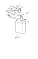
- FIG. 2 is a perspective view of a robot to be simulated.
- FIG. 3 is a schematic top view of the hand.
- FIG. 4 is a block diagram of the robot simulation apparatus.
- FIG. 5 is a diagram illustrating a display example of the selection screen.
- FIG. 6 is a diagram illustrating a display example of the change screen.
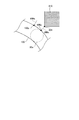
- FIG. 7 is an explanatory diagram illustrating a distance calculation process.
- FIG. 8 is a diagram illustrating a display example of a still image of the robot.
- FIG. 9 is a flowchart showing a processing procedure executed by the robot simulation apparatus.
- FIG. 1 is an explanatory diagram showing an outline of the robot simulation apparatus 20.
- the images 300a and 300b illustrated in FIG. 1 are simulation images generated by the robot simulation apparatus 20.
- the images 300a and 300b are two-dimensional images of the robot 10 and the surrounding environment of the robot 10 as viewed from above.
- the Z axis with the vertical upward direction as the positive direction as the positive direction
- the X axis as the direction along the long side of the transfer chamber 201 as the direction along the long side of the transfer chamber 201
- the direction along the short side of the transfer chamber 201 are shown.
- a three-dimensional orthogonal coordinate system with the Y axis is shown. Such an orthogonal coordinate system may be shown in other drawings used in the following description.
- the transfer chamber 201 is a so-called EFEM (Equipment Front End Module), and is a locally-cleaned casing that allows a clean downflow airflow to flow inside.
- EFEM Equipment Front End Module
- dimensions such as the position, size, and spacing of the openings provided on the side walls of the transfer chamber 201 for installing the cassette 202 and the processing chamber 203 comply with the SEMI (Semiconductor Equipment and Materials International) standard.
- various dimensions in apparatuses such as the cassette 202 and the processing chamber 203 also conform to the SEMI standard.
- the cassette 202 is a so-called FOUP (Front-Opening Unified Pod) and is a device that stores the substrates 30 in multiple stages. Although three cassettes 202 are shown in FIG. 1, the number of cassettes 202 may be an arbitrary number. Further, the mounting position and the number of the processing chambers 203 shown in FIG. 1 may be arbitrary.
- FOUP Front-Opening Unified Pod
- the image 300a is a composite image obtained by combining the robot 10 and the image showing the substrate 30 transported by the robot 10 and the background image 200.
- An image 300a illustrated in FIG. 1 is a composite image of the background image 200 and the still images of the robot 10 and the substrate 30.
- the background image 200 includes an image of the transfer chamber 201 in which the robot 10 is arranged, a cassette 202 provided on the side wall of the transfer chamber 201, and a processing chamber 203 also provided on the side wall. That is, the background image 200 includes an obstacle 210 that is arranged around the robot 10 and may interfere with the robot 10.
- the obstacle 210 is represented by a line or a hatched area.
- the display form is not limited as long as it represents the existence range of the obstacle 210.
- the virtual robot 10 When confirming the interference state between the robot 10 and the substrate 30 and the obstacle 210 using the robot simulation apparatus 20 according to the embodiment, the virtual robot 10 is operated along a previously prepared operation path, and the interference state is determined. Will be confirmed. However, in the past, it has not been said that the possibility of interference between the robot 10 and the obstacle 210 is sufficiently informed to the operator.
- the motion trajectory (hereinafter simply referred to as “trajectory 100”) of the robot 10 or the substrate 30 may interfere with the obstacle 210 as in the image 300b illustrated in FIG.
- the notification image 400 is displayed.
- the robot simulation device 20 is a trajectory 100 that is a range through which the substrate 30 passes in accordance with the operation of the robot 10. Is generated.
- the robot simulation device 20 calculates the distance between the generated trajectory 100 and the obstacle 210 included in the background image 200.
- the robot simulation apparatus 20 determines that the trajectory 100 has approached the obstacle 210, and displays the notification image 400 including the distance information 402 indicating the calculated distance. Generate. Further, the robot simulation device 20 synthesizes the notification image 400 with the synthesized image of the trajectory 100 and the background image 200.
- the notification image 400 may include a mark 401 indicating a corresponding point on the outer periphery of the obstacle 210.
- the distance information 402 included in the notification image 400 may be a distance in an actual environment (“X.XX (mm)” in FIG. 1) as shown in FIG. It is good also as a set of deviation
- the robot simulation apparatus 20 displays the distance between the trajectory 100 and the obstacle 210 included in the background image 200, the possibility of interference between the robot 10 and the surrounding environment is displayed.
- the operator can be notified in an easy-to-understand manner. Thereby, for example, it becomes clear how much the relative position between the robot 10 and the obstacle 210 should be changed, so that the teaching data of the robot 10 can be generated efficiently.
- the locus 100 is shown as a superimposed image in which still images indicating the position of the substrate 30 during operation are superimposed at a predetermined time interval. In this way, by making the trajectory 100 a superimposed image, the passing range of the robot 10 and the substrate 30 can be notified intuitively and easily.
- the present invention is not limited to this, and the outer shape of the range through which the robot 10 and the substrate 30 pass may be generated as the locus 100. Further, such a passing range may be highlighted by changing the display color or blinking.
- the image 300b shown in FIG. 1 shows a case where the range through which the substrate 30 passes is displayed as the trajectory 100, but the target of the trajectory 100 can be selected as will be described later with reference to FIG.
- the robot simulation apparatus 20 can select all or part of the robot 10 that transports the substrate 30 as the target of the trajectory 100.
- the image 300b shows the route 100C at the center of the substrate 30 for reference, but the route 100C may not be displayed.
- one notification image 400 is illustrated, but when there are a plurality of locations to be notified, the same number of notification images 400 as the locations to be notified are displayed. Also good. Moreover, it is good also as displaying only the alerting
- the robot simulation device 20 has a function of changing the relative position between the trajectory 100 and the background image 200, which will be described later with reference to FIG.
- a procedure for calculating the distance between the trajectory 100 and the obstacle 210 included in the background image 200 will be described later with reference to FIG.
- FIG. 2 is a perspective view of the robot 10 to be simulated.
- the robot 10 includes a main body 10 a, a lifting shaft 10 b, a first arm 11, a second arm 12, and a hand 13.
- the robot 10 provided with the two hands 13 is illustrated in FIG. 2, the hand 13 is good also as one.
- the main body 10a is fixed to the floor surface of the transfer chamber 201 (see FIG. 1) and has a built-in lifting mechanism (not shown) that lifts and lowers the lifting shaft 10b.
- the elevating shaft 10b supports the base end portion of the first arm 11 so as to be pivotable about the first axis A1, and moves up and down along the first axis A1.
- the lifting shaft 10b itself may be rotated around the first axis A1.
- the first arm 11 supports the proximal end portion of the second arm 12 at the distal end portion so as to be rotatable around the second axis A2.
- the second arm 12 supports the proximal end portions of the two hands 13 at the distal end portions so as to be independently rotatable about the third axis A3. That is, the hands 13 are independently turned by a rotation mechanism (not shown) arranged coaxially.
- the robot 10 is a three-link horizontal articulated robot including the first arm 11, the second arm 12 and the hand 13. Moreover, since the robot 10 has the lifting mechanism as described above, the robot 10 can access each of the substrates 30 arranged in multiple stages in the cassette 202.
- the robot 10 can access, for example, a processing chamber 203 (see FIG. 1) arranged at a different height from the cassette 202 and an aligner device (not shown) for adjusting the orientation of the substrate.
- the second arm 12 may be omitted from the robot 10 and a two-link horizontal articulated robot of the first arm 11 and the hand 13 may be used.
- FIG. 3 is a schematic top view of the hand 13.
- the substrate 30 placed at the correct position is indicated by a broken line for reference.
- the hand 13 includes a base portion 13a and a fork portion 13b.
- the base end side of the base portion 13a is supported by the second arm 12 (see FIG. 2) so as to be rotatable around the third axis A3.
- the fork portion 13b is provided on the distal end side of the base portion 13a, and the distal end side is divided into two forks.
- the sensor what is called a mapping sensor which detects the board
- the position corresponding to the center of the substrate 30 held by the hand 13 is a reference position 13 ⁇ / b> C of the hand 13.
- a line connecting the third axis A3 and the reference position 13C is a hand center line 13CL indicating the direction of the hand 13.
- the hand 13 includes a gripping mechanism that grips the substrate 30.
- the hand 13 may include a holding mechanism such as a suction mechanism instead of the gripping mechanism.
- FIG. 4 is a block diagram of the robot simulation apparatus 20.
- the robot simulation apparatus 20 includes a control unit 21, a storage unit 22, an input unit 23, and a display unit 24.
- the control unit 21 includes a selection unit 21a, a generation unit 21b, a change unit 21c, a synthesis unit 21d, a display control unit 21e, a calculation unit 21f, a determination unit 21g, and an instruction unit 21h.
- the storage unit 22 stores teaching data 22a and background information 22b.
- the robot simulation device 20 includes, for example, a computer having various types of circuits such as a CPU (Central Processing Unit), a ROM (Read Only Memory), a RAM (Random Access Memory), an HDD (Hard Disk Drive), and an input / output port. including.
- a CPU Central Processing Unit
- ROM Read Only Memory
- RAM Random Access Memory
- HDD Hard Disk Drive
- the CPU of the computer reads, for example, a program stored in the ROM, and executes a selection unit 21a, a generation unit 21b, a change unit 21c, a synthesis unit 21d, a display control unit 21e, a calculation unit 21f, It functions as a determination unit 21g and an instruction unit 21h.
- At least one or all of the selection unit 21a, the generation unit 21b, the change unit 21c, the synthesis unit 21d, the display control unit 21e, the calculation unit 21f, the determination unit 21g, and the instruction unit 21h of the control unit 21 are set to ASIC (Application It can also be configured with hardware such as Specific Integrated Circuit) or FPGA (Field Programmable Gate Array).
- ASIC Application It can also be configured with hardware such as Specific Integrated Circuit) or FPGA (Field Programmable Gate Array).
- the storage unit 22 corresponds to, for example, a RAM or an HDD.
- the RAM and HDD can store teaching data 22a and background information 22b.
- the robot simulation apparatus 20 may acquire the above-described program and various information via another computer or a portable recording medium connected via a wired or wireless network.
- the input unit 23 is an input device such as a keyboard, a touch panel, or a mouse.
- the display unit 24 is a display device such as a liquid crystal display. In FIG. 4, the input unit 23 and the display unit 24 are described separately, but an input / output device that also serves as the input unit 23 and the display unit 24, such as a touch panel display, may be used.
- the robot simulation device 20 includes the input unit 23 and the display unit 24, but at least one of the input unit 23 and the display unit 24 is an external device connected to the robot simulation device 20. It is good also as providing in.
- the selection unit 21 a of the control unit 21 selects the target of the trajectory 100 illustrated in FIG. 1 through an operation on the input unit 23. Then, the selection unit 21a notifies the generation unit 21b of the selected site (hereinafter referred to as “selected site”).
- selected site the generation unit 21b of the selected site
- the generation unit 21b generates a trajectory 100 that is a range through which the selected portion selected by the selection unit 21a passes when the robot 10 performs a predetermined operation. For example, as illustrated in FIG. 1, when the substrate 30 is selected, the generation unit 21 b generates a range through which the substrate 30 passes as a trajectory 100.
- the trajectory 100 can be a superimposed image in which a still image indicating the position of the selected part during the operation of the robot 10 is superimposed at a predetermined time interval.
- the trajectory 100 may be the outer shape of the range through which the selected site passes.
- the generation unit 21b causes the robot 10 to perform the predetermined operation described above by operating the robot 10 according to the teaching data 22a.
- the predetermined operation is, for example, an operation of transporting the substrate 30 from the cassette 202 showing the substrate 30 in the image 300a of FIG. 1 to another cassette 202 or the processing chamber 203.
- the changing unit 21c changes the relative position between the trajectory 100 illustrated in FIG. 1 and the background image 200 through an operation on the input unit 23. Then, the changing unit 21c notifies the combining unit 21d of the changed relative position. Details of the change of the relative position will be described later with reference to FIG.
- the combining unit 21d generates a combined image by combining the trajectory 100 generated by the generating unit 21b and the background image 200 (see FIG. 1) included in the background information 22b.
- the relative position between the trajectory 100 and the background image 200 can be changed via the changing unit 21c.
- the combining unit 21d further combines the notification image 400 illustrated in FIG. 1 with the above-described combined image based on an instruction from the instruction unit 21h described later.
- the combining unit 21d notifies the display control unit 21e of the combined image obtained by combining the notification images 400, and notifies the calculation unit 21f of the trajectory 100, the background image 200, and the relative positions of both.
- the composition unit 21d corrects the teaching data 22a using the changed relative position. Thereby, the teaching data 22a in which the interval between the robot 10 and the obstacle 210 included in the background image 200 is adjusted to a predetermined interval or more can be obtained.
- the display control unit 21e displays the composite image received from the synthesis unit 21d on the display unit 24.
- the display control unit 21e causes the display unit 24 to display a GUI (Graphical User Interface) screen illustrated in FIGS.
- GUI Graphic User Interface
- the calculation unit 21f Based on the trajectory 100, the background image 200, and the relative positions of the two received from the combining unit 21d, the calculation unit 21f corresponds to the distance between the trajectory 100 and the obstacle 210 included in the background image 200 and the outer periphery of the obstacle 210. Calculate points. Then, the calculation unit 21f notifies the determination unit 21g of the calculated distance and point.
- the determination unit 21g determines whether or not the distance received from the calculation unit 21f is smaller than a predetermined threshold value. Then, the determination unit 21g notifies the instruction unit 21h of a set of distances and points that satisfy the determination condition.
- the instruction unit 21h sends the notification image 400 (see FIG. 1) including the distance and point set received from the determination unit 21g to the combining unit 21d so as to further combine the notification image 400 (see FIG. 1) with the combined image of the trajectory 100 and the background image 200. Instruct.
- the combining unit 21d is instructed to display the notification image 400 by the number of pairs.
- the instruction unit 21h displays the notification image 400 even when the determination result by the determination unit 21g changes from approach to non-approach as a result of the relative position between the locus 100 and the background 200 being changed by the change unit 21c.
- the composing unit 21d is instructed to compose the composite image.
- the notification image 400 is not displayed. However, once the notification image 400 is displayed, it is confirmed that the trajectory 100 and the background image 200 are sufficiently separated by displaying the notification image 400 even when the determination result changes from approach to non-approach. It becomes possible to do. Therefore, it is possible to inform the operator that the change of the relative position is appropriate, which contributes to the reduction of the operator's work load.
- the teaching data 22 a is information including a “job” that is a program that defines the operation of the robot 10 including the movement trajectory of the hand 13. Further, as described above, the teaching data 22a is corrected by the combining unit 21d.
- the background information 22b is information including the background image 200 shown in FIG. Further, as already described, the background image 200 includes an area of the obstacle 210 that may come into contact with the robot 10. That is, the background information 22b is information including the area and the position of the obstacle 210 arranged around the robot 10.
- FIG. 5 is a diagram illustrating a display example of the selection screen 310.
- the selection screen 310 includes a display area 311, a selection area 312, an “execute” button, and a “cancel” button.
- the display area 311 displays a selected part that is a part selected in the selection area 312. For example, as shown in FIG. 5, the display area 312 displays a top view of the robot 10 (see FIG. 2) and highlights the selected portion selected in the selection area 312. In FIG. 5, since the hand 13 is selected in the selection area 312, the hand 13 portion is highlighted in the display area 311. Note that the highlighting may be in any form as long as the selected portion can be visually recognized, such as a color change or blinking.
- the selection area 312 check boxes indicating the selected parts and combinations of names are displayed as many as the number of selected parts.
- the selection area 312 includes, for example, a “select all” button and a “select all” button.
- FIG. 5 shows the first arm 11, the elbow part 311a, the second arm 12, the wrist part 311b, the hand 13 and the substrate 30 as selected parts.
- the elbow part 311a can be made into the area
- the wrist portion 311b can be an area where the second arm 12 and the hand 13 overlap when the hand 13 is turned with respect to the second arm 12.
- an input operation for selecting a target portion of the locus 100 (see FIG. 1) is accepted. Then, the part (the hand 13 in FIG. 5) whose check box is checked is selected. Note that a check or non-check can be selected for each check box.
- the selected part is notified to the generation unit 21b (see FIG. 4) by pressing the “execute” button. If the “Cancel” button is pressed, the selection state of the selection area 312 is canceled and the selection screen 310 is not displayed. That is, the selected part is not notified to the generation unit 21b.
- FIG. 6 is a diagram illustrating a display example of the change screen 320.
- the change screen 320 includes the image 300 b illustrated in FIG. 1, a selection area 321, an input area 322, an “execute” button, and a “cancel” button.
- the image 300b includes a trajectory 100, a background image 200, and a notification image 400.
- the notification image 400 includes a mark 401 and distance information 402. Note that the image 300b corresponds to the case where the substrate 30 is selected as a selected portion on the selection screen 310 illustrated in FIG.
- the selection area 321 is an area for selecting which of the trajectory 100 and the background image 200 to move when the relative position between the trajectory 100 and the background image 200 is changed. As shown in FIG. 6, the selection area 321 displays a set of radio buttons and names indicating shift targets. That is, either the locus 100 or the background 200 can be selected as the shift target.
- the input area 322 is an area for inputting a shift amount indicating how much the shift target selected in the selection area 321 is moved in the X axis positive direction (X direction) and the Y axis positive direction (Y direction). It is.
- text boxes 322a and 322b for receiving an input of a shift amount and a set of names are displayed. That is, the shift amount can be input in each of the X direction and the Y direction.
- the locus 100 is selected as the shift target, and “ ⁇ 0.50 (mm)” for the X direction and “ ⁇ 1.00 (mm)” for the Y direction are input as the shift amounts. Shows the case.
- the present invention is not limited thereto, and a set of deviation amounts in the X direction and the Y direction corresponding to the distance may be used. Moreover, it is good also as including both distance and deviation
- the operator can easily determine the shift amount to be input to the input area 322 based on the shift amounts in the X direction and the Y direction displayed in the distance information 402. That is, the operator's workload can be reduced.
- the initial value of the shift amount displayed in the input area 322 may be automatically displayed based on the shift amounts in the X direction and the Y direction displayed in the distance information 402.
- the relative position after the change between the locus 100 and the background image 200 is performed by pressing the “execute” button. Is notified to the combining unit 21d (see FIG. 4). Then, the content of the image 300b is updated so as to correspond to the changed relative position.
- FIG. 6 shows a case where the shift amount is changed by inputting to the text box
- an input component such as a slide bar that changes the shift amount continuously or stepwise may be used.
- the content of the image 300b may be updated in real time so as to correspond to the change in the shift amount.
- the distance information 402 included in the notification image 400 may be updated in real time.
- FIG. 7 is an explanatory diagram illustrating a distance calculation process.
- FIG. 7 illustrates a part of the trajectory 100 and the obstacle 210 that is the target of distance calculation for the range through which the substrate 30 (see FIG. 1 and the like) passes.
- the calculation unit 21f sets the moving point 100p that moves on the outline of the locus 100 shown in FIG. Further, the normal 100n of the locus 100 at the moving point 100p is calculated. When the obstacle 210 and the normal line 100n intersect while moving the moving point 100p along the outline of the trajectory 100, the distance between the moving point 100p and the obstacle 210 is calculated.
- the determination unit 21g compares the calculated distance with a predetermined threshold, and when the calculated distance is smaller than the threshold, the determination unit 21g determines a point on the outer periphery of the obstacle 210 corresponding to the calculated distance as shown in FIG.
- the notification image 400 shown in FIG. when the points on the outer periphery of the obstacle 210 are continuously below the threshold, the point having the smallest distance among the consecutive points is set as the target of the notification image 400.
- a point on the outer periphery of the obstacle 210 corresponding to the smallest distance among the calculated distances may be the target of the notification image 400.
- FIG. 7 a mark 401 (see FIG. 1) indicating a point on the outer periphery of the obstacle 210 corresponding to the minimum distance between the locus 100 and the obstacle 210, and a point 100 a on the outer shape of the locus 100 are shown. Shown for reference. FIG. 7 also shows the outer shape 30a of the substrate 30 corresponding to the point 100a on the outer shape of the trajectory 100 for reference.
- FIG. 8 is a diagram illustrating a display example of a still image of the robot 10.
- FIG. 8 shows the posture of the robot 10 when the substrate 30 is at a position corresponding to the outer shape 30a shown in FIG.
- the trajectory 100 is shown in the image 300b shown in FIGS.
- the operator may want to confirm the posture of the robot 10 corresponding to the displayed notification image 400.
- FIG. 8 a case where a still image of the robot 10 is displayed instead of the locus 100 is shown.
- the present invention is not limited to this, and the locus 100 and the robot 10 may be displayed in a superimposed manner. In this case, it is preferable to superimpose the trajectory 100 on the back side and the robot 10 on the front side because the posture of the robot 10 can be easily seen. Even if the locus 100 is not displayed on the back side, the display form is not limited as long as the posture of the robot 10 can be visually recognized, such as a semi-transparent display.
- FIG. 9 is a flowchart showing a processing procedure executed by the robot simulation apparatus 20.
- the selection unit 21a of the control unit 21 in the robot simulation apparatus 20 receives selection of the target of the trajectory 100 via, for example, the selection screen 310 illustrated in FIG. 5 (step S101). And the production
- the combining unit 21d generates a combined image by combining the locus 100 and the background image 200 (step S103).
- the calculating unit 21f calculates the distance between the trajectory 100 and the obstacle 210 included in the background image 200 in the procedure shown in FIG. 7 (step S104).
- the combining unit 21d determines whether or not the shift operation for changing the relative position between the locus 100 and the background image 200 is performed via the change screen 320 illustrated in FIG. 6 (Step S105). . And when it determines with it being after a shift operation (step S105, Yes), the point alert
- step S105 when the determination condition of step S105 is satisfied (step S105, Yes), the point notified before the shift operation and the point on the obstacle 210 closest to the trajectory 100 become the notification target. In some cases, both are the same point. On the other hand, when the determination condition of step S105 is not satisfied (step S105, No), a point on the obstacle 210 closest to the trajectory 100 is a notification target.
- the synthesis unit 21d generates a notification image 400 including a point and a distance on the obstacle 210 that is a notification target (step S108).
- the locus 100 and the background image 200 are combined into a combined image (step S109).
- the changing unit 21c determines whether or not the above-described shift operation has been performed via the change screen 320 illustrated in FIG. 6 (Step S110). If it is determined that there is a shift operation (step S110, Yes), the relative position between the trajectory 100 and the background image 200 is changed based on the shift amount input to the change screen 320 (step S111). The processes after step S103 are repeated. On the other hand, when the determination condition of step S110 is not satisfied (step S110, No), the process ends.
- the robot simulation apparatus 20 includes the generation unit 21b, the synthesis unit 21d, the display control unit 21e, the calculation unit 21f, the determination unit 21g, and the instruction unit 21h.
- the generation unit 21 b generates a trajectory 100 indicating a range through which the robot 10 that transports the substrate 30 passes.
- the combining unit 21d combines the background image 200 including the obstacles 210 arranged around the robot 10 and the trajectory 100.
- the display control unit 21e causes the display unit 24 to display the combined image combined by the combining unit 21d.
- the calculating unit 21f calculates the distance between the trajectory 100 and the obstacle 210.
- the determination unit 21g determines that the locus 100 has approached the obstacle 210 when the distance calculated by the calculation unit 21f is smaller than a predetermined threshold.
- the instruction unit 21h instructs the combining unit 21d to combine the notification image 400 including the distance calculated by the calculation unit 21f with the combined image. Instruct.
- the robot simulation apparatus 20 it is possible to easily notify the operator of the possibility of interference between the robot 10 and the surrounding environment.
- the robot 10 according to the present embodiment operates based on the teaching data 22a generated by the robot simulation device 20. Therefore, according to the robot 10 according to the present embodiment, interference with the surrounding environment can be prevented.
- the robot 10 is a horizontal articulated robot.
- the robot 10 may be another type of robot such as a so-called serial link robot.
- the shape of the substrate 30 is not limited to a circular shape, and may be other shapes such as a rectangular shape.
Landscapes
- Engineering & Computer Science (AREA)
- Physics & Mathematics (AREA)
- Condensed Matter Physics & Semiconductors (AREA)
- General Physics & Mathematics (AREA)
- Manufacturing & Machinery (AREA)
- Computer Hardware Design (AREA)
- Microelectronics & Electronic Packaging (AREA)
- Power Engineering (AREA)
- Robotics (AREA)
- Mechanical Engineering (AREA)
- Manipulator (AREA)
Abstract
A robot simulation device is provided with a generating section, a compositing section, a display control section, a calculating section, a determining section, and an instructing section. The generating section generates a path that shows the area through which a robot conveying a substrate is to pass. The compositing section composites a background image, which comprises obstacles disposed around the robot, with the path. The display control section displays the composite image composited by the compositing section on a display unit. The calculating section calculates the distances between the path and the obstacles. The determining section determines that the path is near an obstacle when the distance is smaller than a specified threshold. When the determining section determines that the path is near an obstacle, the instructing section instructs the compositing section to composite a notification image, which comprises the distance calculated by the calculating section, with the composite image.
Description
開示の実施形態は、ロボットシミュレーション装置、ロボットシミュレーション方法、ロボットシミュレーションプログラムおよびロボットに関する。
The disclosed embodiment relates to a robot simulation apparatus, a robot simulation method, a robot simulation program, and a robot.
従来、基板搬送ロボットなどのロボットの動作を再現した画像を表示部に表示させることで、ロボットとロボットの周囲環境との位置関係を確認可能とし、ロボットの位置や動作の検討を補助するロボットシミュレーション装置が知られている。
Conventionally, by displaying an image that reproduces the movement of a robot, such as a substrate transfer robot, on the display unit, it is possible to check the positional relationship between the robot and the surrounding environment of the robot, and robot simulation that assists in examining the position and movement of the robot The device is known.
かかるロボットシミュレーション装置としては、周囲環境を2次元画像であらわすとともに、ロボットの動作を再現した3次元の画像を2次元画像に変換したうえで、両2次元画像を合成するものがある(たとえば、特許文献1参照)。
As such a robot simulation apparatus, there is an apparatus that expresses the surrounding environment as a two-dimensional image, converts a three-dimensional image reproducing the operation of the robot into a two-dimensional image, and then combines the two-dimensional images (for example, Patent Document 1).
しかしながら、上記した従来技術のように、ロボットおよび周囲環境をそれぞれ2次元画像であらわして合成する場合であっても、ロボットと周囲環境との干渉の可能性を操作者へわかりやすく報知する観点からは改善の余地がある。
However, even when the robot and the surrounding environment are each represented by a two-dimensional image and combined as in the conventional technique described above, from the viewpoint of easily informing the operator of the possibility of interference between the robot and the surrounding environment. There is room for improvement.
実施形態の一態様は、ロボットと周囲環境との干渉の可能性を操作者へわかりやすく報知することができるロボットシミュレーション装置、ロボットシミュレーション方法、ロボットシミュレーションプログラムおよびロボットを提供することを目的とする。
An object of one embodiment is to provide a robot simulation apparatus, a robot simulation method, a robot simulation program, and a robot that can easily notify an operator of the possibility of interference between the robot and the surrounding environment.
実施形態の一態様に係るロボットシミュレーション装置は、生成部と、合成部と、表示制御部と、算出部と、判定部と、指示部とを備える。生成部は、基板を搬送するロボットが通過する範囲を示す軌跡を生成する。合成部は、前記ロボットのまわりに配置される障害物を含む背景画像と前記軌跡とを合成する。表示制御部は、前記合成部によって合成された合成画像を表示部に表示させる。算出部は、前記軌跡と前記障害物との距離を算出する。判定部は、前記距離が所定の閾値よりも小さい場合に、前記軌跡が前記障害物に接近したと判定する。指示部は、前記判定部によって前記軌跡が前記障害物に接近したと判定された場合に、前記算出部が算出した前記距離を含んだ報知画像を前記合成画像に合成するように前記合成部に指示する。
The robot simulation apparatus according to an aspect of the embodiment includes a generation unit, a synthesis unit, a display control unit, a calculation unit, a determination unit, and an instruction unit. The generation unit generates a trajectory indicating a range through which the robot that transports the substrate passes. The synthesizing unit synthesizes the background image including the obstacle arranged around the robot and the locus. The display control unit causes the display unit to display the synthesized image synthesized by the synthesis unit. The calculation unit calculates a distance between the trajectory and the obstacle. The determination unit determines that the trajectory has approached the obstacle when the distance is smaller than a predetermined threshold. When the determination unit determines that the locus has approached the obstacle, the instruction unit causes the combining unit to combine the notification image including the distance calculated by the calculation unit with the combined image. Instruct.
実施形態の一態様によれば、ロボットと周囲環境との干渉の可能性を操作者へわかりやすく報知することが可能なロボットシミュレーション装置、ロボットシミュレーション方法、ロボットシミュレーションプログラムおよびロボットを提供することができる。
According to one embodiment of the present invention, it is possible to provide a robot simulation apparatus, a robot simulation method, a robot simulation program, and a robot that can easily notify the operator of the possibility of interference between the robot and the surrounding environment. .
以下、添付図面を参照して、本願の開示するロボットシミュレーション装置、ロボットシミュレーション方法、ロボットシミュレーションプログラムおよびロボットを詳細に説明する。なお、以下に示す実施形態によりこの発明が限定されるものではない。
Hereinafter, a robot simulation apparatus, a robot simulation method, a robot simulation program, and a robot disclosed in the present application will be described in detail with reference to the accompanying drawings. In addition, this invention is not limited by embodiment shown below.
また、以下に示す実施形態では、「鉛直」、「中心」といった表現を用いる場合があるが、厳密にこれらの状態を満たすことを要しない。すなわち、上記した各表現は、製造精度、設置精度、処理精度、検出精度などのずれを許容するものとする。
In the embodiment described below, expressions such as “vertical” and “center” may be used, but it is not necessary to strictly satisfy these conditions. That is, each expression described above allows for deviations in manufacturing accuracy, installation accuracy, processing accuracy, detection accuracy, and the like.
まず、実施形態に係るロボットシミュレーション装置20(図4参照)の概要について図1を用いて説明する。図1は、ロボットシミュレーション装置20の概要を示す説明図である。なお、図1に示した画像300a,300bは、ロボットシミュレーション装置20が生成するシミュレーション画像である。また、画像300a,300bは、ロボット10およびロボット10の周囲環境を上方からみた2次元画像である。
First, an outline of the robot simulation apparatus 20 (see FIG. 4) according to the embodiment will be described with reference to FIG. FIG. 1 is an explanatory diagram showing an outline of the robot simulation apparatus 20. Note that the images 300a and 300b illustrated in FIG. 1 are simulation images generated by the robot simulation apparatus 20. The images 300a and 300b are two-dimensional images of the robot 10 and the surrounding environment of the robot 10 as viewed from above.
なお、図1には、説明をわかりやすくするために、鉛直上向きを正方向とするZ軸、搬送室201の長辺に沿った向きをX軸、搬送室201の短辺に沿った向きをY軸とする3次元の直交座標系を示している。かかる直交座標系は、以下の説明で用いる他の図面においても示す場合がある。
In FIG. 1, in order to make the explanation easy to understand, the Z axis with the vertical upward direction as the positive direction, the X axis as the direction along the long side of the transfer chamber 201, and the direction along the short side of the transfer chamber 201 are shown. A three-dimensional orthogonal coordinate system with the Y axis is shown. Such an orthogonal coordinate system may be shown in other drawings used in the following description.
ここで、搬送室201は、いわゆるEFEM(Equipment Front End Module)であり、清浄なダウンフローの気流を内部に流す局所クリーン化された筐体である。また、カセット202や処理室203を設置するために搬送室201の側壁に設けられる開口の位置や大きさ、間隔といった寸法は、SEMI(Semiconductor Equipment and Materials International)規格に準拠している。また、カセット202や処理室203といった装置における各種寸法についても、SEMI規格に準拠している。
Here, the transfer chamber 201 is a so-called EFEM (Equipment Front End Module), and is a locally-cleaned casing that allows a clean downflow airflow to flow inside. In addition, dimensions such as the position, size, and spacing of the openings provided on the side walls of the transfer chamber 201 for installing the cassette 202 and the processing chamber 203 comply with the SEMI (Semiconductor Equipment and Materials International) standard. In addition, various dimensions in apparatuses such as the cassette 202 and the processing chamber 203 also conform to the SEMI standard.
カセット202は、いわゆるFOUP(Front-Opening Unified Pod)であり、基板30を多段に収納する機器である。なお、図1では、3つのカセット202を示しているが、カセット202の個数は任意の数であってよい。また、図1に示した処理室203の取付位置や個数についても任意であってよい。
The cassette 202 is a so-called FOUP (Front-Opening Unified Pod) and is a device that stores the substrates 30 in multiple stages. Although three cassettes 202 are shown in FIG. 1, the number of cassettes 202 may be an arbitrary number. Further, the mounting position and the number of the processing chambers 203 shown in FIG. 1 may be arbitrary.
まず、画像300aについて説明する。図1に示すように、画像300aは、ロボット10およびロボット10によって搬送される基板30を示す画像と、背景画像200とを合成した合成画像である。なお、図1に示した画像300aは、背景画像200と、ロボット10および基板30の静止画像との合成画像である。
First, the image 300a will be described. As shown in FIG. 1, the image 300 a is a composite image obtained by combining the robot 10 and the image showing the substrate 30 transported by the robot 10 and the background image 200. An image 300a illustrated in FIG. 1 is a composite image of the background image 200 and the still images of the robot 10 and the substrate 30.
背景画像200には、ロボット10が配置される搬送室201、搬送室201の側壁に設けられるカセット202、同じく側壁に設けられる処理室203の画像が含まれる。つまり、背景画像200には、ロボット10のまわりに配置され、ロボット10と干渉する可能性がある障害物210が含まれる。なお、図1では、障害物210を線や、ハッチングを付した領域であらわしているが、障害物210の存在範囲をあらわすものであれば、その表示形態は問わない。
The background image 200 includes an image of the transfer chamber 201 in which the robot 10 is arranged, a cassette 202 provided on the side wall of the transfer chamber 201, and a processing chamber 203 also provided on the side wall. That is, the background image 200 includes an obstacle 210 that is arranged around the robot 10 and may interfere with the robot 10. In FIG. 1, the obstacle 210 is represented by a line or a hatched area. However, the display form is not limited as long as it represents the existence range of the obstacle 210.
実施形態に係るロボットシミュレーション装置20を用いてロボット10や基板30と、障害物210との干渉状態を確認する場合、仮想的なロボット10を、あらかじめ用意した動作経路で動作させ、かかる干渉状態を確認することになる。しかしながら、従来は、ロボット10と障害物210との干渉の可能性を操作者に対して十分にわかりやすく報知しているとはいえなかった。
When confirming the interference state between the robot 10 and the substrate 30 and the obstacle 210 using the robot simulation apparatus 20 according to the embodiment, the virtual robot 10 is operated along a previously prepared operation path, and the interference state is determined. Will be confirmed. However, in the past, it has not been said that the possibility of interference between the robot 10 and the obstacle 210 is sufficiently informed to the operator.
そこで、実施形態に係るロボットシミュレーション装置20では、図1に示す画像300bのように、ロボット10や基板30の動作軌跡(以下、単に「軌跡100」という)が、障害物210と干渉の可能性がある場合に、報知画像400を表示することとした。
Therefore, in the robot simulation apparatus 20 according to the embodiment, the motion trajectory (hereinafter simply referred to as “trajectory 100”) of the robot 10 or the substrate 30 may interfere with the obstacle 210 as in the image 300b illustrated in FIG. When there is, the notification image 400 is displayed.
具体的には、画像300bに示すように、たとえば、軌跡100の対象として基板30が選択された場合、ロボットシミュレーション装置20は、ロボット10の動作に伴って基板30が通過する範囲である軌跡100を生成する。
Specifically, as shown in the image 300 b, for example, when the substrate 30 is selected as the target of the trajectory 100, the robot simulation device 20 is a trajectory 100 that is a range through which the substrate 30 passes in accordance with the operation of the robot 10. Is generated.
つづいて、ロボットシミュレーション装置20は、生成した軌跡100と背景画像200に含まれる障害物210との距離を算出する。そして、ロボットシミュレーション装置20は、算出した距離が所定の閾値よりも小さい場合には、軌跡100が障害物210に接近したと判定し、算出した距離を示す距離情報402を含んだ報知画像400を生成する。また、ロボットシミュレーション装置20は、軌跡100と背景画像200との合成画像に報知画像400を合成する。
Subsequently, the robot simulation device 20 calculates the distance between the generated trajectory 100 and the obstacle 210 included in the background image 200. When the calculated distance is smaller than the predetermined threshold, the robot simulation apparatus 20 determines that the trajectory 100 has approached the obstacle 210, and displays the notification image 400 including the distance information 402 indicating the calculated distance. Generate. Further, the robot simulation device 20 synthesizes the notification image 400 with the synthesized image of the trajectory 100 and the background image 200.
ここで、報知画像400には、障害物210の外周上の該当する点を示すマーク401を含めることとしてもよい。また、報知画像400に含まれる距離情報402については、図1に示したように、実際の環境における距離(図1では、「X.XX(mm)」)としてもよいし、かかる距離に対応するX軸およびY軸についてのずれ量の組としてもよい。また、距離およびずれ量の双方を含めることとしてもよい。
Here, the notification image 400 may include a mark 401 indicating a corresponding point on the outer periphery of the obstacle 210. Further, the distance information 402 included in the notification image 400 may be a distance in an actual environment (“X.XX (mm)” in FIG. 1) as shown in FIG. It is good also as a set of deviation | shift amount about X-axis and Y-axis. Moreover, it is good also as including both distance and deviation | shift amount.
このように、実施形態に係るロボットシミュレーション装置20は、軌跡100と、背景画像200に含まれる障害物210との距離を表示することとしたので、ロボット10と周囲環境との干渉の可能性を操作者へわかりやすく報知することができる。これにより、たとえば、ロボット10と障害物210との相対位置をどの程度変更すればよいかが明確となるため、ロボット10の教示データを効率よく生成することができる。
Thus, since the robot simulation apparatus 20 according to the embodiment displays the distance between the trajectory 100 and the obstacle 210 included in the background image 200, the possibility of interference between the robot 10 and the surrounding environment is displayed. The operator can be notified in an easy-to-understand manner. Thereby, for example, it becomes clear how much the relative position between the robot 10 and the obstacle 210 should be changed, so that the teaching data of the robot 10 can be generated efficiently.
なお、図1に示した画像300bでは、軌跡100として、動作中における基板30の位置を示す静止画像を所定の時間間隔で重畳した重畳画像とする場合を示した。このように、軌跡100を重畳画像とすることで、ロボット10や基板30の通過範囲を直感的にわかりやすく報知することができる。
In the image 300b shown in FIG. 1, the locus 100 is shown as a superimposed image in which still images indicating the position of the substrate 30 during operation are superimposed at a predetermined time interval. In this way, by making the trajectory 100 a superimposed image, the passing range of the robot 10 and the substrate 30 can be notified intuitively and easily.
しかしながら、これに限らず、ロボット10や基板30が通過する範囲の外形を軌跡100として生成することとしてもよい。また、かかる通過する範囲を表示色の変更や点滅などによって強調表示することとしてもよい。
However, the present invention is not limited to this, and the outer shape of the range through which the robot 10 and the substrate 30 pass may be generated as the locus 100. Further, such a passing range may be highlighted by changing the display color or blinking.
また、図1に示す画像300bでは、基板30が通過する範囲を軌跡100として表示する場合を示しているが、図5を用いて後述するように、軌跡100の対象は選択可能である。
Further, the image 300b shown in FIG. 1 shows a case where the range through which the substrate 30 passes is displayed as the trajectory 100, but the target of the trajectory 100 can be selected as will be described later with reference to FIG.
たとえば、ロボットシミュレーション装置20では、軌跡100の対象として、基板30を搬送するロボット10の全体や一部を選択することができる。なお、画像300bには、参考のため、基板30の中心の経路100Cを示しているが、経路100Cについては表示しなくてもよい。
For example, the robot simulation apparatus 20 can select all or part of the robot 10 that transports the substrate 30 as the target of the trajectory 100. The image 300b shows the route 100C at the center of the substrate 30 for reference, but the route 100C may not be displayed.
また、図1に示す画像300bでは、1つの報知画像400を例示しているが、報知対象となる箇所が複数ある場合には、報知対象となる箇所と同数の報知画像400を表示することとしてもよい。また、報知対象となる箇所のうち最も接近している箇所に対応する報知画像400のみを表示することとしてもよい。
In addition, in the image 300b illustrated in FIG. 1, one notification image 400 is illustrated, but when there are a plurality of locations to be notified, the same number of notification images 400 as the locations to be notified are displayed. Also good. Moreover, it is good also as displaying only the alerting | reporting image 400 corresponding to the location which is closest among the location used as alerting | reporting object.
また、ロボットシミュレーション装置20では、軌跡100と背景画像200との相対位置を変更する機能を有しているが、この点については図6を用いて後述する。また、軌跡100と、背景画像200に含まれる障害物210との距離の算出手順については図7を用いて後述する。
Further, the robot simulation device 20 has a function of changing the relative position between the trajectory 100 and the background image 200, which will be described later with reference to FIG. A procedure for calculating the distance between the trajectory 100 and the obstacle 210 included in the background image 200 will be described later with reference to FIG.
次に、ロボットシミュレーション装置20によるシミュレーションの対象となるロボット10の構成について図2を用いて説明する。図2は、シミュレーション対象となるロボット10の斜視図である。同図に示すように、ロボット10は、本体部10aと、昇降軸10bと、第1アーム11と、第2アーム12と、ハンド13とを備える。なお、図2には、2つのハンド13を備えるロボット10を例示しているが、ハンド13は1つとしてもよい。
Next, the configuration of the robot 10 to be simulated by the robot simulation apparatus 20 will be described with reference to FIG. FIG. 2 is a perspective view of the robot 10 to be simulated. As shown in the figure, the robot 10 includes a main body 10 a, a lifting shaft 10 b, a first arm 11, a second arm 12, and a hand 13. In addition, although the robot 10 provided with the two hands 13 is illustrated in FIG. 2, the hand 13 is good also as one.
本体部10aは、搬送室201(図1参照)の床面等に固定され、昇降軸10bを昇降させる昇降機構(図示せず)を内蔵する。昇降軸10bは、第1アーム11の基端部を第1軸A1まわりに旋回可能に支持するとともに、第1軸A1に沿って昇降する。なお、昇降軸10b自体を第1軸A1まわりに回転させることとしてもよい。
The main body 10a is fixed to the floor surface of the transfer chamber 201 (see FIG. 1) and has a built-in lifting mechanism (not shown) that lifts and lowers the lifting shaft 10b. The elevating shaft 10b supports the base end portion of the first arm 11 so as to be pivotable about the first axis A1, and moves up and down along the first axis A1. The lifting shaft 10b itself may be rotated around the first axis A1.
第1アーム11は、第2アーム12の基端部を第2軸A2まわりに旋回可能に先端部で支持する。第2アーム12は、2つのハンド13の基端部を第3軸A3まわりにそれぞれ独立して旋回可能に先端部で支持する。つまり、ハンド13は、同軸配置される回転機構(図示せず)によって、それぞれ独立して旋回する。
The first arm 11 supports the proximal end portion of the second arm 12 at the distal end portion so as to be rotatable around the second axis A2. The second arm 12 supports the proximal end portions of the two hands 13 at the distal end portions so as to be independently rotatable about the third axis A3. That is, the hands 13 are independently turned by a rotation mechanism (not shown) arranged coaxially.
このように、ロボット10は、第1アーム11、第2アーム12およびハンド13の3リンクの水平多関節ロボットである。また、ロボット10は、上記したように、昇降機構を有しているので、カセット202内に多段配置される基板30に対してそれぞれアクセスすることができる。
As described above, the robot 10 is a three-link horizontal articulated robot including the first arm 11, the second arm 12 and the hand 13. Moreover, since the robot 10 has the lifting mechanism as described above, the robot 10 can access each of the substrates 30 arranged in multiple stages in the cassette 202.
さらに、ロボット10は、たとえば、カセット202と異なる高さに配置される処理室203(図1参照)や、基板の向きを整えるアライナ装置(図示せず)にアクセスすることもできる。なお、ロボット10から第2アーム12を省略し、第1アーム11およびハンド13の2リンクの水平多関節ロボットとしてもよい。
Furthermore, the robot 10 can access, for example, a processing chamber 203 (see FIG. 1) arranged at a different height from the cassette 202 and an aligner device (not shown) for adjusting the orientation of the substrate. The second arm 12 may be omitted from the robot 10 and a two-link horizontal articulated robot of the first arm 11 and the hand 13 may be used.
次に、図2に示したハンド13について図3を用いてさらに詳細に説明する。図3は、ハンド13の上面模式図である。なお、図3以降では、説明をわかりやすくするために、1つのハンド13のみを示すこととする。また、図3には、正しい位置に載置された基板30を参考のため破線で示している。
Next, the hand 13 shown in FIG. 2 will be described in more detail with reference to FIG. FIG. 3 is a schematic top view of the hand 13. In FIG. 3 and subsequent figures, only one hand 13 is shown for easy understanding. In FIG. 3, the substrate 30 placed at the correct position is indicated by a broken line for reference.
図3に示すように、ハンド13は、基部13aと、フォーク部13bとを備える。基部13aの基端側は、第3軸A3まわりに旋回可能に第2アーム12(図2参照)によって支持される。フォーク部13bは、基部13aの先端側に設けられ、先端側が二股にわかれている。なお、二股にわかれたフォーク部13bの各先端側にカセット202に収容された基板30を検知するセンサ(いわゆるマッピングセンサ)を設けることとしてもよい。
As shown in FIG. 3, the hand 13 includes a base portion 13a and a fork portion 13b. The base end side of the base portion 13a is supported by the second arm 12 (see FIG. 2) so as to be rotatable around the third axis A3. The fork portion 13b is provided on the distal end side of the base portion 13a, and the distal end side is divided into two forks. In addition, it is good also as providing the sensor (what is called a mapping sensor) which detects the board | substrate 30 accommodated in the cassette 202 in each front end side of the fork part 13b divided into two forks.
また、図3に示すように、ハンド13によって保持される基板30の中心に対応する位置は、ハンド13の基準位置13Cである。そして、たとえば、第3軸A3と基準位置13Cとを結ぶ線が、ハンド13の向きを示すハンド中心線13CLである。なお、ハンド13は、基板30を把持する把持機構を備えるものとする。また、ハンド13は、把持機構のかわりに吸着機構などの保持機構を備えることとしてもよい。
Further, as shown in FIG. 3, the position corresponding to the center of the substrate 30 held by the hand 13 is a reference position 13 </ b> C of the hand 13. For example, a line connecting the third axis A3 and the reference position 13C is a hand center line 13CL indicating the direction of the hand 13. Note that the hand 13 includes a gripping mechanism that grips the substrate 30. The hand 13 may include a holding mechanism such as a suction mechanism instead of the gripping mechanism.
次に、ロボットシミュレーション装置20について図4を用いて説明する。図4は、ロボットシミュレーション装置20のブロック図である。図4に示すように、ロボットシミュレーション装置20は、制御部21と、記憶部22と、入力部23と、表示部24とを備える。
Next, the robot simulation apparatus 20 will be described with reference to FIG. FIG. 4 is a block diagram of the robot simulation apparatus 20. As shown in FIG. 4, the robot simulation apparatus 20 includes a control unit 21, a storage unit 22, an input unit 23, and a display unit 24.
制御部21は、選択部21aと、生成部21bと、変更部21cと、合成部21dと、表示制御部21eと、算出部21fと、判定部21gと、指示部21hとを備える。また、記憶部22は、教示データ22aと、背景情報22bとを記憶する。
The control unit 21 includes a selection unit 21a, a generation unit 21b, a change unit 21c, a synthesis unit 21d, a display control unit 21e, a calculation unit 21f, a determination unit 21g, and an instruction unit 21h. The storage unit 22 stores teaching data 22a and background information 22b.
ここで、ロボットシミュレーション装置20は、たとえば、CPU(Central Processing Unit)、ROM(Read Only Memory)、RAM(Random Access Memory)、HDD(Hard Disk Drive)、入出力ポートなどを有するコンピュータや各種の回路を含む。
Here, the robot simulation device 20 includes, for example, a computer having various types of circuits such as a CPU (Central Processing Unit), a ROM (Read Only Memory), a RAM (Random Access Memory), an HDD (Hard Disk Drive), and an input / output port. including.
コンピュータのCPUは、たとえば、ROMに記憶されたプログラムを読み出して実行することによって、制御部21の選択部21a、生成部21b、変更部21c、合成部21d、表示制御部21e、算出部21f、判定部21gおよび指示部21hとして機能する。
The CPU of the computer reads, for example, a program stored in the ROM, and executes a selection unit 21a, a generation unit 21b, a change unit 21c, a synthesis unit 21d, a display control unit 21e, a calculation unit 21f, It functions as a determination unit 21g and an instruction unit 21h.
また、制御部21の選択部21a、生成部21b、変更部21c、合成部21d、表示制御部21e、算出部21f、判定部21gおよび指示部21hの少なくともいずれか一つまたは全部をASIC(Application Specific Integrated Circuit)やFPGA(Field Programmable Gate Array)等のハードウェアで構成することもできる。
In addition, at least one or all of the selection unit 21a, the generation unit 21b, the change unit 21c, the synthesis unit 21d, the display control unit 21e, the calculation unit 21f, the determination unit 21g, and the instruction unit 21h of the control unit 21 are set to ASIC (Application It can also be configured with hardware such as Specific Integrated Circuit) or FPGA (Field Programmable Gate Array).
また、記憶部22は、たとえば、RAMやHDDに対応する。RAMやHDDは、教示データ22aおよび背景情報22bを記憶することができる。なお、ロボットシミュレーション装置20は、有線や無線のネットワークで接続された他のコンピュータや可搬型記録媒体を介して上記したプログラムや各種情報を取得することとしてもよい。
The storage unit 22 corresponds to, for example, a RAM or an HDD. The RAM and HDD can store teaching data 22a and background information 22b. Note that the robot simulation apparatus 20 may acquire the above-described program and various information via another computer or a portable recording medium connected via a wired or wireless network.
入力部23は、キーボードやタッチパネル、マウスといった入力デバイスである。また、表示部24は、液晶ディスプレイなどの表示デバイスである。なお、図4では、入力部23と表示部24とを別々に記載しているが、タッチパネルディスプレイのように、入力部23および表示部24を兼ねる入出力デバイスを用いることとしてもよい。
The input unit 23 is an input device such as a keyboard, a touch panel, or a mouse. The display unit 24 is a display device such as a liquid crystal display. In FIG. 4, the input unit 23 and the display unit 24 are described separately, but an input / output device that also serves as the input unit 23 and the display unit 24, such as a touch panel display, may be used.
また、図4では、ロボットシミュレーション装置20が、入力部23および表示部24を備える場合を示しているが、入力部23および表示部24の少なくとも一方を、ロボットシミュレーション装置20と接続される外部装置に設けることとしてもよい。
4 shows a case where the robot simulation device 20 includes the input unit 23 and the display unit 24, but at least one of the input unit 23 and the display unit 24 is an external device connected to the robot simulation device 20. It is good also as providing in.
制御部21の選択部21aは、図1に示した軌跡100の対象を、入力部23に対する操作を介して選択する。そして、選択部21aは、選択した部位(以下、「選択部位」という)を生成部21bへ通知する。ここで、軌跡100の対象として、基板30を搬送するロボット10の全体や一部を選択することが可能であるが、この点については、図5を用いて後述する。
The selection unit 21 a of the control unit 21 selects the target of the trajectory 100 illustrated in FIG. 1 through an operation on the input unit 23. Then, the selection unit 21a notifies the generation unit 21b of the selected site (hereinafter referred to as “selected site”). Here, as the target of the trajectory 100, it is possible to select the whole or a part of the robot 10 that transports the substrate 30, and this point will be described later with reference to FIG.
生成部21bは、選択部21aによって選択された選択部位が、ロボット10に所定の動作を行わせた場合に通過する範囲である軌跡100を生成する。たとえば、図1に示したように、基板30が選択された場合には、生成部21bは、基板30が通過する範囲を軌跡100として生成する。
The generation unit 21b generates a trajectory 100 that is a range through which the selected portion selected by the selection unit 21a passes when the robot 10 performs a predetermined operation. For example, as illustrated in FIG. 1, when the substrate 30 is selected, the generation unit 21 b generates a range through which the substrate 30 passes as a trajectory 100.
なお、軌跡100は、図1に示したように、ロボット10の動作中における選択部位の位置を示す静止画像を所定の時間間隔で重畳した重畳画像とすることができる。また、軌跡100は、選択部位が通過する範囲の外形としてもよい。
Note that, as shown in FIG. 1, the trajectory 100 can be a superimposed image in which a still image indicating the position of the selected part during the operation of the robot 10 is superimposed at a predetermined time interval. The trajectory 100 may be the outer shape of the range through which the selected site passes.
また、生成部21bは、ロボット10を教示データ22aに従って動作させることで、ロボット10に上記した所定の動作を行わせる。ここで、所定の動作とは、たとえば、図1の画像300aで基板30を示したカセット202から、他のカセット202や処理室203へ基板30を搬送する動作である。
Further, the generation unit 21b causes the robot 10 to perform the predetermined operation described above by operating the robot 10 according to the teaching data 22a. Here, the predetermined operation is, for example, an operation of transporting the substrate 30 from the cassette 202 showing the substrate 30 in the image 300a of FIG. 1 to another cassette 202 or the processing chamber 203.
変更部21cは、図1に示した軌跡100と、背景画像200との相対位置を、入力部23に対する操作を介して変更する。そして、変更部21cは、変更後の相対位置を合成部21dへ通知する。なお、相対位置の変更の詳細については、図6を用いて後述する。
The changing unit 21c changes the relative position between the trajectory 100 illustrated in FIG. 1 and the background image 200 through an operation on the input unit 23. Then, the changing unit 21c notifies the combining unit 21d of the changed relative position. Details of the change of the relative position will be described later with reference to FIG.
合成部21dは、生成部21bが生成した軌跡100と、背景情報22bに含まれる背景画像200(図1参照)とを合成した合成画像を生成する。ここで、軌跡100と、背景画像200との相対位置は、変更部21cを介して変更することができる。また、合成部21dは、後述する指示部21hによる指示に基づき、図1に示した報知画像400を上記した合成画像に対してさらに合成する。
The combining unit 21d generates a combined image by combining the trajectory 100 generated by the generating unit 21b and the background image 200 (see FIG. 1) included in the background information 22b. Here, the relative position between the trajectory 100 and the background image 200 can be changed via the changing unit 21c. The combining unit 21d further combines the notification image 400 illustrated in FIG. 1 with the above-described combined image based on an instruction from the instruction unit 21h described later.
そして、合成部21dは、報知画像400が合成された合成画像を表示制御部21eへ通知するとともに、軌跡100、背景画像200および両者の相対位置を算出部21fへ通知する。
Then, the combining unit 21d notifies the display control unit 21e of the combined image obtained by combining the notification images 400, and notifies the calculation unit 21f of the trajectory 100, the background image 200, and the relative positions of both.
なお、合成部21dは、軌跡100と、背景画像200との相対位置の変更が完了した場合には、変更された相対位置を用いて教示データ22aを補正する。これにより、ロボット10と、背景画像200に含まれる障害物210との間隔を所定の間隔以上に調整した教示データ22aを得ることができる。
In addition, when the change of the relative position between the locus 100 and the background image 200 is completed, the composition unit 21d corrects the teaching data 22a using the changed relative position. Thereby, the teaching data 22a in which the interval between the robot 10 and the obstacle 210 included in the background image 200 is adjusted to a predetermined interval or more can be obtained.
表示制御部21eは、合成部21dから受け取った合成画像を表示部24へ表示させる。たとえば、表示制御部21eは、図5や図6に示すGUI(Graphical User Interface)画面を表示部24へ表示させる。
The display control unit 21e displays the composite image received from the synthesis unit 21d on the display unit 24. For example, the display control unit 21e causes the display unit 24 to display a GUI (Graphical User Interface) screen illustrated in FIGS.
算出部21fは、合成部21dから受け取った軌跡100、背景画像200および両者の相対位置に基づき、軌跡100と、背景画像200に含まれる障害物210との距離および障害物210の外周における該当する点を算出する。そして、算出部21fは、算出した距離および点を判定部21gへ通知する。
Based on the trajectory 100, the background image 200, and the relative positions of the two received from the combining unit 21d, the calculation unit 21f corresponds to the distance between the trajectory 100 and the obstacle 210 included in the background image 200 and the outer periphery of the obstacle 210. Calculate points. Then, the calculation unit 21f notifies the determination unit 21g of the calculated distance and point.
判定部21gは、算出部21fから受け取った距離が、あらかじめ定められた閾値よりも小さいか否かを判定する。そして、判定部21gは、判定条件を満たした距離および点の組を指示部21hへ通知する。
The determination unit 21g determines whether or not the distance received from the calculation unit 21f is smaller than a predetermined threshold value. Then, the determination unit 21g notifies the instruction unit 21h of a set of distances and points that satisfy the determination condition.
指示部21hは、判定部21gから受け取った距離および点の組を含んだ報知画像400(図1参照)を、軌跡100と背景画像200との合成画像にさらに合成するように、合成部21dへ指示する。ここで、距離および点の組が複数ある場合には、報知画像400を組の数だけ表示するように合成部21dへ指示することになる。
The instruction unit 21h sends the notification image 400 (see FIG. 1) including the distance and point set received from the determination unit 21g to the combining unit 21d so as to further combine the notification image 400 (see FIG. 1) with the combined image of the trajectory 100 and the background image 200. Instruct. Here, when there are a plurality of pairs of distances and points, the combining unit 21d is instructed to display the notification image 400 by the number of pairs.
また、指示部21hは、変更部21cにおいて軌跡100と背景200との相対位置を変更された結果、判定部21gによる判定結果が接近から非接近へ変わった場合であっても、報知画像400を合成画像に合成するように合成部21dに指示する。
In addition, the instruction unit 21h displays the notification image 400 even when the determination result by the determination unit 21g changes from approach to non-approach as a result of the relative position between the locus 100 and the background 200 being changed by the change unit 21c. The composing unit 21d is instructed to compose the composite image.
すなわち、判定部21gによる判定結果が接近から非接近へ変わった場合、本来なら報知画像400を表示しないことになる。しかし、いったん報知画像400を表示した場合には、判定結果が接近から非接近へ変わった場合でもあえて報知画像400を表示することで、軌跡100と背景画像200とが十分に離れたことを確認することが可能となる。したがって、相対位置の変更が適切であったことを操作者へ伝えることができ、操作者の作業負担の軽減に寄与する。
That is, when the determination result by the determination unit 21g changes from approach to non-approach, the notification image 400 is not displayed. However, once the notification image 400 is displayed, it is confirmed that the trajectory 100 and the background image 200 are sufficiently separated by displaying the notification image 400 even when the determination result changes from approach to non-approach. It becomes possible to do. Therefore, it is possible to inform the operator that the change of the relative position is appropriate, which contributes to the reduction of the operator's work load.
教示データ22aは、ハンド13の移動軌跡をはじめとするロボット10の動作を規定するプログラムである「ジョブ」を含んだ情報である。また、上記したように、教示データ22aは、合成部21dによって補正される。
The teaching data 22 a is information including a “job” that is a program that defines the operation of the robot 10 including the movement trajectory of the hand 13. Further, as described above, the teaching data 22a is corrected by the combining unit 21d.
背景情報22bは、図1に示した背景画像200を含んだ情報である。また、既に説明したように、背景画像200は、ロボット10に接触する可能性がある障害物210の領域を含んでいる。つまり、背景情報22bは、ロボット10のまわりに配置される障害物210の領域および位置を含んだ情報である。
The background information 22b is information including the background image 200 shown in FIG. Further, as already described, the background image 200 includes an area of the obstacle 210 that may come into contact with the robot 10. That is, the background information 22b is information including the area and the position of the obstacle 210 arranged around the robot 10.
次に、図4に示した選択部21aに対応する選択画面310について図5を用いて説明する。図5は、選択画面310の表示例を示す図である。図5に示すように、選択画面310は、表示エリア311と、選択エリア312と、「実行」ボタンおよび「キャンセル」ボタンを備える。
Next, the selection screen 310 corresponding to the selection unit 21a shown in FIG. 4 will be described with reference to FIG. FIG. 5 is a diagram illustrating a display example of the selection screen 310. As shown in FIG. 5, the selection screen 310 includes a display area 311, a selection area 312, an “execute” button, and a “cancel” button.
表示エリア311は、選択エリア312で選択された部位である選択部位を表示する。たとえば、図5に示すように、表示エリア312は、ロボット10(図2参照)の上面図などを表示するとともに、選択エリア312で選択された選択部位を強調表示する。なお、図5では、選択エリア312でハンド13が選択されているので、表示エリア311ではハンド13部分を強調表示している。なお、強調表示は、色の変更や、点滅など、選択部位を視認可能であれば、その態様は問わない。
The display area 311 displays a selected part that is a part selected in the selection area 312. For example, as shown in FIG. 5, the display area 312 displays a top view of the robot 10 (see FIG. 2) and highlights the selected portion selected in the selection area 312. In FIG. 5, since the hand 13 is selected in the selection area 312, the hand 13 portion is highlighted in the display area 311. Note that the highlighting may be in any form as long as the selected portion can be visually recognized, such as a color change or blinking.
選択エリア312には、選択部位を示すチェックボックスおよび名称の組が、選択部位の数だけ表示される。また、選択エリア312は、たとえば、「すべて選択」ボタンおよび「すべて非選択」ボタンを備える。
In the selection area 312, check boxes indicating the selected parts and combinations of names are displayed as many as the number of selected parts. The selection area 312 includes, for example, a “select all” button and a “select all” button.
図5では、選択部位として、第1アーム11、肘部311a、第2アーム12、手首部311b、ハンド13および基板30を示している。ここで、肘部311aは、たとえば、第2アーム12を第1アーム11に対して旋回させた場合に、第1アーム11と第2アーム12とが重なりあう領域とすることができる。また、手首部311bは、ハンド13を第2アーム12に対して旋回させた場合に、第2アーム12とハンド13とが重なりあう領域とすることができる。
FIG. 5 shows the first arm 11, the elbow part 311a, the second arm 12, the wrist part 311b, the hand 13 and the substrate 30 as selected parts. Here, the elbow part 311a can be made into the area | region where the 1st arm 11 and the 2nd arm 12 overlap, for example, when the 2nd arm 12 is rotated with respect to the 1st arm 11. FIG. Further, the wrist portion 311b can be an area where the second arm 12 and the hand 13 overlap when the hand 13 is turned with respect to the second arm 12.
このように、選択エリア312では、軌跡100(図1参照)の対象とする部位を選択する入力操作を受け付ける。そして、チェックボックスをチェックされた部位(図5では、ハンド13)を選択部位とする。なお、チェックボックスごとにチェック、非チェックを選択可能である。
Thus, in the selection area 312, an input operation for selecting a target portion of the locus 100 (see FIG. 1) is accepted. Then, the part (the hand 13 in FIG. 5) whose check box is checked is selected. Note that a check or non-check can be selected for each check box.
ここで、すべての選択部位を選択したい場合には、すべてのチェックボックスをチェックすればよい。または、「すべて選択」ボタンを押下すれば、すべてのチェックボックスがチェックされる。なお、誤ってチェックした場合には、「すべて非選択」ボタンを押下すれば、すべてのチェックボックスが非チェック状態に戻る。
If you want to select all the selected parts, check all the check boxes. Or, if the “Select All” button is pressed, all the check boxes are checked. If a check is made by mistake, all check boxes return to the unchecked state by pressing the “Deselect All” button.
そして、選択エリア312における選択部位の選択が完了したならば、「実行」ボタンを押下することで、選択部位が生成部21b(図4参照)へ通知される。なお、「キャンセル」ボタンを押下すると、選択エリア312の選択状態はキャンセルされ、選択画面310は、非表示状態となる。つまり、選択部位は生成部21bへ通知されることはない。
When the selection of the selected part in the selection area 312 is completed, the selected part is notified to the generation unit 21b (see FIG. 4) by pressing the “execute” button. If the “Cancel” button is pressed, the selection state of the selection area 312 is canceled and the selection screen 310 is not displayed. That is, the selected part is not notified to the generation unit 21b.
このように、軌跡100の対象とする部位を選択可能とすることで、たとえば、ロボット10の関節部分など、特に着目したい部位の軌跡100を表示することが可能となり、操作者の作業負荷を低減することができる。
In this way, by making it possible to select a target part of the trajectory 100, it is possible to display the trajectory 100 of a part that is particularly focused on, such as a joint portion of the robot 10, and to reduce the workload on the operator. can do.
次に、図4に示した変更部21cに対応する変更画面320について図6を用いて説明する。図6は、変更画面320の表示例を示す図である。図6に示すように、変更画面320は、図1に示した画像300bと、選択エリア321と、入力エリア322と、「実行」ボタンおよび「キャンセル」ボタンを備える。
Next, the change screen 320 corresponding to the change unit 21c shown in FIG. 4 will be described with reference to FIG. FIG. 6 is a diagram illustrating a display example of the change screen 320. As illustrated in FIG. 6, the change screen 320 includes the image 300 b illustrated in FIG. 1, a selection area 321, an input area 322, an “execute” button, and a “cancel” button.
画像300bは、軌跡100と、背景画像200と、報知画像400とを含む。また、報知画像400はマーク401と、距離情報402とを含む。なお、画像300bは、図5に示した選択画面310で、基板30が選択部位として選択された場合に対応する。
The image 300b includes a trajectory 100, a background image 200, and a notification image 400. The notification image 400 includes a mark 401 and distance information 402. Note that the image 300b corresponds to the case where the substrate 30 is selected as a selected portion on the selection screen 310 illustrated in FIG.
選択エリア321は、軌跡100と背景画像200との相対位置を変更する際に、軌跡100および背景画像200のうち、どちらを動かすかを選択するエリアである。図6に示すように、選択エリア321には、シフト対象を示すラジオボタンおよび名称の組が表示される。つまり、シフト対象として、軌跡100および背景200のうち、どちらかを選択可能である。
The selection area 321 is an area for selecting which of the trajectory 100 and the background image 200 to move when the relative position between the trajectory 100 and the background image 200 is changed. As shown in FIG. 6, the selection area 321 displays a set of radio buttons and names indicating shift targets. That is, either the locus 100 or the background 200 can be selected as the shift target.
入力エリア322は、選択エリア321で選択されたシフト対象を、X軸の正方向(X方向)およびY軸の正方向(Y方向)に、それぞれどれだけ動かすかを示すシフト量を入力するエリアである。入力エリア322には、シフト量の入力を受け付けるテキストボックス322a,322bおよび名称の組が表示される。つまり、シフト量は、X方向およびY方向のそれぞれに対して入力可能である。
The input area 322 is an area for inputting a shift amount indicating how much the shift target selected in the selection area 321 is moved in the X axis positive direction (X direction) and the Y axis positive direction (Y direction). It is. In the input area 322, text boxes 322a and 322b for receiving an input of a shift amount and a set of names are displayed. That is, the shift amount can be input in each of the X direction and the Y direction.
なお、図6では、シフト対象として、軌跡100が選択され、シフト量として、X方向について「-0.50(mm)」、Y方向について「-1.00(mm)」が、それぞれ入力された場合を示している。
In FIG. 6, the locus 100 is selected as the shift target, and “−0.50 (mm)” for the X direction and “−1.00 (mm)” for the Y direction are input as the shift amounts. Shows the case.
なお、図6では、報知画像400の距離情報402として、軌跡100と、背景画像200に含まれる障害物210との距離「X.XX(mm)」を表示する場合を示している。しかしながら、これに限らず、かかる距離に対応するX方向およびY方向についてのずれ量の組としてもよい。また、距離およびずれ量の双方を含めることとしてもよい。
6 shows a case where the distance “X.XX (mm)” between the trajectory 100 and the obstacle 210 included in the background image 200 is displayed as the distance information 402 of the notification image 400. However, the present invention is not limited thereto, and a set of deviation amounts in the X direction and the Y direction corresponding to the distance may be used. Moreover, it is good also as including both distance and deviation | shift amount.
このようにすることで、距離情報402に表示されたX方向およびY方向のずれ量に基づき、操作者は、入力エリア322に入力するシフト量を容易に決定することができる。つまり、操作者の作業負担を軽減することができる。なお、この場合、入力エリア322に表示するシフト量の初期値を、距離情報402に表示されたX方向およびY方向のずれ量に基づいて自動的に表示することとしてもよい。
In this way, the operator can easily determine the shift amount to be input to the input area 322 based on the shift amounts in the X direction and the Y direction displayed in the distance information 402. That is, the operator's workload can be reduced. In this case, the initial value of the shift amount displayed in the input area 322 may be automatically displayed based on the shift amounts in the X direction and the Y direction displayed in the distance information 402.
そして、選択エリア321におけるシフト対象の選択と、入力エリア322におけるシフト量の入力が完了したならば、「実行」ボタンを押下することで、軌跡100と、背景画像200との変更後の相対位置が、合成部21d(図4参照)へ通知される。そして、画像300bの内容が変更後の相対位置に対応するように更新される。
When the selection of the shift target in the selection area 321 and the input of the shift amount in the input area 322 are completed, the relative position after the change between the locus 100 and the background image 200 is performed by pressing the “execute” button. Is notified to the combining unit 21d (see FIG. 4). Then, the content of the image 300b is updated so as to correspond to the changed relative position.
なお、「キャンセル」ボタンを押下すると、選択エリア321の選択状態と、入力エリア322の入力情報とはキャンセルされ、変更画面320は、非表示状態となる。つまり、変更後の相対位置は合成部21dへ通知されることはない。
When the “Cancel” button is pressed, the selection state of the selection area 321 and the input information of the input area 322 are canceled, and the change screen 320 is not displayed. That is, the changed relative position is not notified to the combining unit 21d.
なお、図6では、シフト量をテキストボックスに対する入力によって変更する場合を示したが、たとえば、スライドバーなどシフト量を連続的または階段状に変化させる入力部品を用いることとしてもよい。また、この場合、画像300bの内容をシフト量の変化に対応するようにリアルタイムに更新してもよい。この場合、報知画像400に含まれる距離情報402についてもリアルタイムに更新してもよい。
Although FIG. 6 shows a case where the shift amount is changed by inputting to the text box, for example, an input component such as a slide bar that changes the shift amount continuously or stepwise may be used. In this case, the content of the image 300b may be updated in real time so as to correspond to the change in the shift amount. In this case, the distance information 402 included in the notification image 400 may be updated in real time.
次に、図4に示した算出部21fが行う距離の算出処理について図7を用いて説明する。図7は、距離の算出処理を示す説明図である。なお、図7には、基板30(図1等を参照)が通過する範囲についての軌跡100および距離算出の対象となる障害物210の一部を例示している。
Next, distance calculation processing performed by the calculation unit 21f illustrated in FIG. 4 will be described with reference to FIG. FIG. 7 is an explanatory diagram illustrating a distance calculation process. FIG. 7 illustrates a part of the trajectory 100 and the obstacle 210 that is the target of distance calculation for the range through which the substrate 30 (see FIG. 1 and the like) passes.
算出部21f(図4参照)は、図7に示した軌跡100の外形、すなわち、軌跡100の輪郭上を移動する移動点100pを設定する。また、移動点100pにおける軌跡100の法線100nを算出する。そして、移動点100pを軌跡100の外形に沿って移動させつつ、障害物210と法線100nが交わった場合には、移動点100pと障害物210との距離を算出する。
The calculation unit 21f (see FIG. 4) sets the moving point 100p that moves on the outline of the locus 100 shown in FIG. Further, the normal 100n of the locus 100 at the moving point 100p is calculated. When the obstacle 210 and the normal line 100n intersect while moving the moving point 100p along the outline of the trajectory 100, the distance between the moving point 100p and the obstacle 210 is calculated.
また、判定部21gは、算出した距離を所定の閾値と比較し、算出した距離が、かかる閾値よりも小さい場合には、算出した距離に対応する障害物210の外周上の点を、図1に示した報知画像400の対象とする。ここで、障害物210の外周上の点が連続して閾値を下回る場合には、かかる連続した点のうち距離が最も小さい点を報知画像400の対象とする。なお、閾値と比較する代わりに、算出した距離のうち最も小さい距離に対応する障害物210の外周上の点を、報知画像400の対象とすることとしてもよい。
In addition, the determination unit 21g compares the calculated distance with a predetermined threshold, and when the calculated distance is smaller than the threshold, the determination unit 21g determines a point on the outer periphery of the obstacle 210 corresponding to the calculated distance as shown in FIG. The notification image 400 shown in FIG. Here, when the points on the outer periphery of the obstacle 210 are continuously below the threshold, the point having the smallest distance among the consecutive points is set as the target of the notification image 400. Instead of comparing with the threshold value, a point on the outer periphery of the obstacle 210 corresponding to the smallest distance among the calculated distances may be the target of the notification image 400.
なお、図7には、軌跡100と、障害物210との最小距離に対応する障害物210の外周上の点を指すマーク401(図1参照)と、軌跡100の外形上の点100aとを参考のため示している。また、図7には、軌跡100の外形上の点100aに対応する基板30の外形30aについても参考のため示している。
In FIG. 7, a mark 401 (see FIG. 1) indicating a point on the outer periphery of the obstacle 210 corresponding to the minimum distance between the locus 100 and the obstacle 210, and a point 100 a on the outer shape of the locus 100 are shown. Shown for reference. FIG. 7 also shows the outer shape 30a of the substrate 30 corresponding to the point 100a on the outer shape of the trajectory 100 for reference.
次に、報知画像400に対応するロボット10の静止画像の表示例について図8を用いて説明することとする。図8は、ロボット10の静止画像の表示例を示す図である。なお、図8では、図7に示した外形30aに対応する位置に基板30がある場合のロボット10の姿勢を示している。
Next, a display example of a still image of the robot 10 corresponding to the notification image 400 will be described with reference to FIG. FIG. 8 is a diagram illustrating a display example of a still image of the robot 10. FIG. 8 shows the posture of the robot 10 when the substrate 30 is at a position corresponding to the outer shape 30a shown in FIG.
図1や図6に示した画像300bでは、軌跡100を示していた。しかし、マーク401および距離情報402を含んだ報知画像400を表示した場合、表示した報知画像400に対応するロボット10の姿勢を操作者が確認したい場合がある。
The trajectory 100 is shown in the image 300b shown in FIGS. However, when the notification image 400 including the mark 401 and the distance information 402 is displayed, the operator may want to confirm the posture of the robot 10 corresponding to the displayed notification image 400.
そこで、図8に示したように、報知画像400に対応するロボット10の静止画像を表示することとすれば、ロボット10あるいは基板30と障害物210とが接近した状態におけるロボット10の姿勢の確認が容易となる。したがって、ロボット10の静止画像を表示することとすれば、ロボット10の位置や動作の再検討を容易に行うことができ、作業負荷の軽減に寄与する。
Therefore, as shown in FIG. 8, if a still image of the robot 10 corresponding to the notification image 400 is displayed, confirmation of the posture of the robot 10 when the robot 10 or the substrate 30 and the obstacle 210 are close to each other is confirmed. Becomes easy. Therefore, if the still image of the robot 10 is displayed, the position and operation of the robot 10 can be easily reconsidered, which contributes to a reduction in workload.
なお、図8では、軌跡100の代わりにロボット10の静止画像を表示する場合を示した。しかしながら、これに限らず、軌跡100およびロボット10を重畳させて表示することとしてもよい。この場合、軌跡100を背面側に、ロボット10を前面側に重畳させることとすれば、ロボット10の姿勢を視認しやすいので好ましい。なお、軌跡100を背面側に表示しなくとも、軌跡100を半透明表示にするなど、ロボット10の姿勢を視認可能であればその表示形態は問わない。
In FIG. 8, a case where a still image of the robot 10 is displayed instead of the locus 100 is shown. However, the present invention is not limited to this, and the locus 100 and the robot 10 may be displayed in a superimposed manner. In this case, it is preferable to superimpose the trajectory 100 on the back side and the robot 10 on the front side because the posture of the robot 10 can be easily seen. Even if the locus 100 is not displayed on the back side, the display form is not limited as long as the posture of the robot 10 can be visually recognized, such as a semi-transparent display.
次に、ロボットシミュレーション装置20(図4参照)が実行する処理手順について図9を用いて説明する。図9は、ロボットシミュレーション装置20が実行する処理手順を示すフローチャートである。
Next, a processing procedure executed by the robot simulation apparatus 20 (see FIG. 4) will be described with reference to FIG. FIG. 9 is a flowchart showing a processing procedure executed by the robot simulation apparatus 20.
ロボットシミュレーション装置20における制御部21の選択部21aは、軌跡100の対象の選択を、たとえば、図5に示した選択画面310を介して受け付ける(ステップS101)。そして、生成部21bは、ステップS101の選択結果を反映した軌跡100を生成する(ステップS102)。
The selection unit 21a of the control unit 21 in the robot simulation apparatus 20 receives selection of the target of the trajectory 100 via, for example, the selection screen 310 illustrated in FIG. 5 (step S101). And the production | generation part 21b produces | generates the locus | trajectory 100 reflecting the selection result of step S101 (step S102).
つづいて、合成部21dは、軌跡100と背景画像200とを合成した合成画像を生成する(ステップS103)。また、算出部21fは、たとえば、図7に示した手順で軌跡100と、背景画像200に含まれる障害物210との距離を算出する(ステップS104)。
Subsequently, the combining unit 21d generates a combined image by combining the locus 100 and the background image 200 (step S103). For example, the calculating unit 21f calculates the distance between the trajectory 100 and the obstacle 210 included in the background image 200 in the procedure shown in FIG. 7 (step S104).
また、合成部21dは、図6に示した変更画面320を介して軌跡100と背景画像200との相対位置を変更するシフト操作が行われた後であるか否かを判定する(ステップS105)。そして、シフト操作後であると判定した場合には(ステップS105,Yes)、シフト操作前に報知した点を報知対象に加える(ステップS106)。一方、シフト操作が行われる前だと判定した場合には(ステップS105,No)、軌跡100に最も近い障害物210上の点を報知対象とする(ステップS107)。
Further, the combining unit 21d determines whether or not the shift operation for changing the relative position between the locus 100 and the background image 200 is performed via the change screen 320 illustrated in FIG. 6 (Step S105). . And when it determines with it being after a shift operation (step S105, Yes), the point alert | reported before the shift operation is added to notification object (step S106). On the other hand, if it is determined that the shift operation has not been performed (No at Step S105), a point on the obstacle 210 closest to the trajectory 100 is set as a notification target (Step S107).
すなわち、ステップS105の判定条件を満たした場合には(ステップS105,Yes)、シフト操作前に報知した点および軌跡100に最も近い障害物210上の点が報知対象となる。なお、両者が同一の点である場合もある。一方、ステップS105の判定条件を満たさなかった場合には(ステップS105,No)、軌跡100に最も近い障害物210上の点が報知対象となる。
That is, when the determination condition of step S105 is satisfied (step S105, Yes), the point notified before the shift operation and the point on the obstacle 210 closest to the trajectory 100 become the notification target. In some cases, both are the same point. On the other hand, when the determination condition of step S105 is not satisfied (step S105, No), a point on the obstacle 210 closest to the trajectory 100 is a notification target.
つづいて、合成部21dは、指示部21hの指示に基づき、報知対象となった障害物210上の点および距離を含んだ報知画像400を生成し(ステップS108)、生成した報知画像400を、軌跡100および背景画像200の合成画像へ合成する(ステップS109)。
Subsequently, based on the instruction from the instruction unit 21h, the synthesis unit 21d generates a notification image 400 including a point and a distance on the obstacle 210 that is a notification target (step S108). The locus 100 and the background image 200 are combined into a combined image (step S109).
つづいて、変更部21cは、図6に示した変更画面320を介して上記したシフト操作が行われたか否かを判定する(ステップS110)。そして、シフト操作ありと判定された場合には(ステップS110,Yes)、変更画面320に入力されたシフト量に基づいて軌跡100と、背景画像200との相対位置を変更し(ステップS111)、ステップS103以降の処理を繰り返す。一方、ステップS110の判定条件を満たさなかった場合には(ステップS110,No)、処理を終了する。
Subsequently, the changing unit 21c determines whether or not the above-described shift operation has been performed via the change screen 320 illustrated in FIG. 6 (Step S110). If it is determined that there is a shift operation (step S110, Yes), the relative position between the trajectory 100 and the background image 200 is changed based on the shift amount input to the change screen 320 (step S111). The processes after step S103 are repeated. On the other hand, when the determination condition of step S110 is not satisfied (step S110, No), the process ends.
上述してきたように、本実施形態に係るロボットシミュレーション装置20は、生成部21bと、合成部21dと、表示制御部21eと、算出部21fと、判定部21gと、指示部21hとを備える。生成部21bは、基板30を搬送するロボット10が通過する範囲を示す軌跡100を生成する。合成部21dは、ロボット10のまわりに配置される障害物210を含む背景画像200と軌跡100とを合成する。
As described above, the robot simulation apparatus 20 according to this embodiment includes the generation unit 21b, the synthesis unit 21d, the display control unit 21e, the calculation unit 21f, the determination unit 21g, and the instruction unit 21h. The generation unit 21 b generates a trajectory 100 indicating a range through which the robot 10 that transports the substrate 30 passes. The combining unit 21d combines the background image 200 including the obstacles 210 arranged around the robot 10 and the trajectory 100.
表示制御部21eは、合成部21dによって合成された合成画像を表示部24に表示させる。算出部21fは、軌跡100と障害物210との距離を算出する。判定部21gは、算出部21fによって算出された距離が所定の閾値よりも小さい場合に、軌跡100が障害物210に接近したと判定する。指示部21hは、判定部21gによって軌跡100が障害物210に接近したと判定された場合に、算出部21fが算出した距離を含んだ報知画像400を合成画像に合成するように合成部21dに指示する。
The display control unit 21e causes the display unit 24 to display the combined image combined by the combining unit 21d. The calculating unit 21f calculates the distance between the trajectory 100 and the obstacle 210. The determination unit 21g determines that the locus 100 has approached the obstacle 210 when the distance calculated by the calculation unit 21f is smaller than a predetermined threshold. When the determination unit 21g determines that the locus 100 has approached the obstacle 210, the instruction unit 21h instructs the combining unit 21d to combine the notification image 400 including the distance calculated by the calculation unit 21f with the combined image. Instruct.
したがって、本実施形態に係るロボットシミュレーション装置20によれば、ロボット10と周囲環境との干渉の可能性を操作者へわかりやすく報知することができる。
Therefore, according to the robot simulation apparatus 20 according to the present embodiment, it is possible to easily notify the operator of the possibility of interference between the robot 10 and the surrounding environment.
また、本実施形態に係るロボット10は、ロボットシミュレーション装置20が生成する教示データ22aに基づいて動作することとした。したがって、本実施形態に係るロボット10によれば、周囲環境との干渉を防止することができる。
In addition, the robot 10 according to the present embodiment operates based on the teaching data 22a generated by the robot simulation device 20. Therefore, according to the robot 10 according to the present embodiment, interference with the surrounding environment can be prevented.
なお、上記した実施形態では、ロボット10が水平多関節ロボットである場合を示したが、ロボット10は、いわゆるシリアルリンクロボットなどの他のタイプのロボットであってもよい。また、基板30の形状は、円状に限らず、矩形状など他の形状であってもよい。
In the above embodiment, the robot 10 is a horizontal articulated robot. However, the robot 10 may be another type of robot such as a so-called serial link robot. Further, the shape of the substrate 30 is not limited to a circular shape, and may be other shapes such as a rectangular shape.
さらなる効果や変形例は、当業者によって容易に導き出すことができる。このため、本発明のより広範な態様は、以上のように表しかつ記述した特定の詳細および代表的な実施形態に限定されるものではない。したがって、添付の特許請求の範囲およびその均等物によって定義される総括的な発明の概念の精神または範囲から逸脱することなく、様々な変更が可能である。
Further effects and modifications can be easily derived by those skilled in the art. Thus, the broader aspects of the present invention are not limited to the specific details and representative embodiments shown and described above. Accordingly, various modifications can be made without departing from the spirit or scope of the general inventive concept as defined by the appended claims and their equivalents.
10 ロボット
10a 本体部
10b 昇降軸
11 第1アーム
12 第2アーム
13 ハンド
13a 基部
13b フォーク部
13C 基準位置
13CL ハンド中心線
20 ロボットシミュレーション装置
21 制御部
21a 選択部
21b 生成部
21c 変更部
21d 合成部
21e 表示制御部
21f 算出部
21g 判定部
21h 指示部
22 記憶部
22a 教示データ
22b 背景情報
23 入力部
24 表示部
30 基板
100 軌跡
200 背景画像
210 障害物
400 報知画像 DESCRIPTION OFSYMBOLS 10 Robot 10a Main-body part 10b Elevating shaft 11 1st arm 12 2nd arm 13 Hand 13a Base 13b Fork part 13C Reference position 13CL Hand center line 20 Robot simulation apparatus 21 Control part 21a Selection part 21b Generation part 21c Change part 21d Composition part 21e Display control unit 21f Calculation unit 21g Determination unit 21h Instruction unit 22 Storage unit 22a Teaching data 22b Background information 23 Input unit 24 Display unit 30 Substrate 100 Trajectory 200 Background image 210 Obstacle 400 Notification image
10a 本体部
10b 昇降軸
11 第1アーム
12 第2アーム
13 ハンド
13a 基部
13b フォーク部
13C 基準位置
13CL ハンド中心線
20 ロボットシミュレーション装置
21 制御部
21a 選択部
21b 生成部
21c 変更部
21d 合成部
21e 表示制御部
21f 算出部
21g 判定部
21h 指示部
22 記憶部
22a 教示データ
22b 背景情報
23 入力部
24 表示部
30 基板
100 軌跡
200 背景画像
210 障害物
400 報知画像 DESCRIPTION OF
Claims (11)
- 基板を搬送するロボットが通過する範囲を示す軌跡を生成する生成部と、
前記ロボットのまわりに配置される障害物を含む背景画像と前記軌跡とを合成する合成部と、
前記合成部によって合成された合成画像を表示部に表示させる表示制御部と、
前記軌跡と前記障害物との距離を算出する算出部と、
前記距離が所定の閾値よりも小さい場合に、前記軌跡が前記障害物に接近したと判定する判定部と、
前記判定部によって前記軌跡が前記障害物に接近したと判定された場合に、前記算出部が算出した前記距離を含んだ報知画像を前記合成画像に合成するように前記合成部に指示する指示部と
を備えることを特徴とするロボットシミュレーション装置。 A generating unit that generates a trajectory indicating a range through which a robot that transports a substrate passes;
A synthesis unit that synthesizes a background image including an obstacle arranged around the robot and the locus;
A display control unit that causes a display unit to display a combined image combined by the combining unit;
A calculation unit for calculating a distance between the trajectory and the obstacle;
A determination unit that determines that the locus has approached the obstacle when the distance is smaller than a predetermined threshold;
When the determination unit determines that the locus has approached the obstacle, the instruction unit instructs the combining unit to combine the notification image including the distance calculated by the calculation unit with the combined image. A robot simulation apparatus comprising: - 前記生成部は、
動作中における前記ロボットの静止画像を所定の時間間隔で重畳した重畳画像を、前記軌跡として生成すること
を特徴とする請求項1に記載のロボットシミュレーション装置。 The generator is
The robot simulation apparatus according to claim 1, wherein a superimposed image in which a still image of the robot during operation is superimposed at a predetermined time interval is generated as the trajectory. - 前記指示部は、
前記距離と当該距離に対応する前記障害物の外周における点とを含んだ前記報知画像を、前記合成画像に合成するように前記合成部に指示すること
を特徴とする請求項2に記載のロボットシミュレーション装置。 The instruction unit includes:
The robot according to claim 2, wherein the synthesizing unit is instructed to synthesize the notification image including the distance and a point on the outer periphery of the obstacle corresponding to the distance with the synthesized image. Simulation device. - 前記指示部は、
最も小さい前記距離と当該距離に対応する前記点とを含んだ前記報知画像を、前記合成画像に合成するように前記合成部に指示すること
を特徴とする請求項3に記載のロボットシミュレーション装置。 The instruction unit includes:
The robot simulation apparatus according to claim 3, wherein the synthesizing unit is instructed to synthesize the notification image including the smallest distance and the point corresponding to the distance with the synthesized image. - 前記指示部は、
前記点に対応する前記ロボットの前記静止画像を、前記合成画像に合成するように前記合成部に指示すること
を特徴とする請求項4に記載のロボットシミュレーション装置。 The instruction unit includes:
The robot simulation apparatus according to claim 4, wherein the synthesis unit is instructed to synthesize the still image of the robot corresponding to the point with the synthesized image. - 前記ロボットにおける所定の部位および前記基板のうち1または複数を前記軌跡の対象として選択させる選択部
を備え、
前記生成部は、
前記選択部において選択された前記対象について前記軌跡を生成すること
を特徴とする請求項1~5のいずれか一つに記載のロボットシミュレーション装置。 A selection unit that selects one or more of the predetermined part and the substrate of the robot as the target of the trajectory;
The generator is
The robot simulation apparatus according to any one of claims 1 to 5, wherein the trajectory is generated for the object selected by the selection unit. - 前記合成部が合成する前記背景画像と前記軌跡との相対位置を変更させる変更部
を備えることを特徴とする請求項1~6のいずれか一つに記載のロボットシミュレーション装置。 The robot simulation apparatus according to any one of claims 1 to 6, further comprising a changing unit that changes a relative position between the background image synthesized by the synthesizing unit and the locus. - 前記指示部は、
前記変更部において前記相対位置を変更された結果、前記判定部による判定結果が接近から非接近へ変わった場合であっても、前記報知画像を前記合成画像に合成するように前記合成部に指示すること
を特徴とする請求項7に記載のロボットシミュレーション装置。 The instruction unit includes:
As a result of changing the relative position in the changing unit, the combining unit is instructed to combine the notification image with the combined image even when the determination result by the determining unit changes from approach to non-approach. The robot simulation apparatus according to claim 7, wherein: - 基板を搬送するロボットが通過する範囲を示す軌跡を生成する工程と、
前記ロボットのまわりに配置される障害物を含む背景画像と前記軌跡とを合成する工程と、
前記合成する工程によって合成された合成画像を表示部に表示させる工程と、
前記軌跡と前記障害物との距離を算出する工程と、
前記距離が所定の閾値よりも小さい場合に、前記軌跡が前記障害物に接近したと判定する工程と、
前記判定する工程によって前記軌跡が前記障害物に接近したと判定された場合に、前記算出する工程で算出した前記距離を含んだ報知画像を前記合成画像に合成するように前記合成する工程に指示する工程と
を含むことを特徴とするロボットシミュレーション方法。 Generating a trajectory indicating a range through which a robot carrying the substrate passes;
Synthesizing a background image including obstacles arranged around the robot and the trajectory;
Displaying a synthesized image synthesized by the synthesizing step on a display unit;
Calculating a distance between the trajectory and the obstacle;
Determining that the trajectory has approached the obstacle when the distance is less than a predetermined threshold;
Instructing the synthesizing step to synthesize the notification image including the distance calculated in the calculating step with the synthesized image when it is determined in the determining step that the locus has approached the obstacle. A robot simulation method comprising the steps of: - 基板を搬送するロボットが通過する範囲を示す軌跡を生成する手順と、
前記ロボットのまわりに配置される障害物を含む背景画像と前記軌跡とを合成する手順と、
前記合成する手順によって合成された合成画像を表示部に表示させる手順と、
前記軌跡と前記障害物との距離を算出する手順と、
前記距離が所定の閾値よりも小さい場合に、前記軌跡が前記障害物に接近したと判定する手順と、
前記判定する手順によって前記軌跡が前記障害物に接近したと判定された場合に、前記算出する手順で算出した前記距離を含んだ報知画像を前記合成画像に合成するように前記合成する手順に指示する手順と
をコンピュータに実行させることを特徴とするロボットシミュレーションプログラム。 A procedure for generating a trajectory indicating a range through which a robot carrying a substrate passes;
A procedure for synthesizing a background image including an obstacle placed around the robot and the locus;
A procedure for displaying a synthesized image synthesized by the procedure of synthesizing on a display unit;
Calculating the distance between the trajectory and the obstacle;
A procedure for determining that the trajectory has approached the obstacle when the distance is smaller than a predetermined threshold;
Instructing the compositing procedure to synthesize the notification image including the distance calculated in the calculating procedure with the composite image when the trajectory is determined to have approached the obstacle by the determining procedure. A robot simulation program that causes a computer to execute - 基板を搬送するロボットが通過する範囲を示す軌跡を生成する生成部と、
前記ロボットのまわりに配置される障害物を含む背景画像と前記軌跡とを合成する合成部と、
前記合成部によって合成された合成画像を表示部に表示させる表示制御部と、
前記軌跡と前記障害物との距離を算出する算出部と、
前記距離が所定の閾値よりも小さい場合に、前記軌跡が前記障害物に接近したと判定する判定部と、
前記判定部によって前記軌跡が前記障害物に接近したと判定された場合に、前記算出部が算出した前記距離を含んだ報知画像を前記合成画像に合成するように前記合成部に指示する指示部と
を備えるロボットシミュレーション装置が生成する教示データに基づいて動作することを特徴とするロボット。 A generating unit that generates a trajectory indicating a range through which a robot that transports a substrate passes;
A synthesis unit that synthesizes a background image including an obstacle arranged around the robot and the locus;
A display control unit that causes a display unit to display a combined image combined by the combining unit;
A calculation unit for calculating a distance between the trajectory and the obstacle;
A determination unit that determines that the locus has approached the obstacle when the distance is smaller than a predetermined threshold;
When the determination unit determines that the locus has approached the obstacle, the instruction unit instructs the combining unit to combine the notification image including the distance calculated by the calculation unit with the combined image. A robot that operates based on teaching data generated by a robot simulation device comprising:
Priority Applications (1)
| Application Number | Priority Date | Filing Date | Title |
|---|---|---|---|
| PCT/JP2015/085080 WO2017103997A1 (en) | 2015-12-15 | 2015-12-15 | Robot simulation device, robot simulation method, robot simulation program, and robot |
Applications Claiming Priority (1)
| Application Number | Priority Date | Filing Date | Title |
|---|---|---|---|
| PCT/JP2015/085080 WO2017103997A1 (en) | 2015-12-15 | 2015-12-15 | Robot simulation device, robot simulation method, robot simulation program, and robot |
Publications (1)
| Publication Number | Publication Date |
|---|---|
| WO2017103997A1 true WO2017103997A1 (en) | 2017-06-22 |
Family
ID=59056105
Family Applications (1)
| Application Number | Title | Priority Date | Filing Date |
|---|---|---|---|
| PCT/JP2015/085080 WO2017103997A1 (en) | 2015-12-15 | 2015-12-15 | Robot simulation device, robot simulation method, robot simulation program, and robot |
Country Status (1)
| Country | Link |
|---|---|
| WO (1) | WO2017103997A1 (en) |
Citations (3)
| Publication number | Priority date | Publication date | Assignee | Title |
|---|---|---|---|---|
| JP2010155328A (en) * | 2009-01-01 | 2010-07-15 | Sony Corp | Path planning device, path planning method, and computer program |
| JP2011161549A (en) * | 2010-02-08 | 2011-08-25 | Denso Wave Inc | Device for displaying robot movement track |
| JP2015093345A (en) * | 2013-11-11 | 2015-05-18 | 株式会社安川電機 | Robot simulation device, robot simulation method, and robot simulation program |
-
2015
- 2015-12-15 WO PCT/JP2015/085080 patent/WO2017103997A1/en active Application Filing
Patent Citations (3)
| Publication number | Priority date | Publication date | Assignee | Title |
|---|---|---|---|---|
| JP2010155328A (en) * | 2009-01-01 | 2010-07-15 | Sony Corp | Path planning device, path planning method, and computer program |
| JP2011161549A (en) * | 2010-02-08 | 2011-08-25 | Denso Wave Inc | Device for displaying robot movement track |
| JP2015093345A (en) * | 2013-11-11 | 2015-05-18 | 株式会社安川電機 | Robot simulation device, robot simulation method, and robot simulation program |
Similar Documents
| Publication | Publication Date | Title |
|---|---|---|
| JP6127925B2 (en) | Robot simulation apparatus, robot simulation method, and robot simulation program | |
| US20230060472A1 (en) | Teaching device, teaching method, and robot system | |
| US11213945B2 (en) | Robot simulator, robot system and simulation method | |
| US11072070B2 (en) | Trajectory planning apparatus, trajectory planning method, and production system | |
| KR102416306B1 (en) | Information processing apparatus and control method of display apparatus | |
| JP4441409B2 (en) | Robot simulation apparatus and simulation program | |
| JP6468159B2 (en) | Transport system and transport method | |
| TWI630670B (en) | Method and system for detecting and correcting problematic advanced process control parameters | |
| US20150363935A1 (en) | Robot, robotic system, and control device | |
| JP4737668B2 (en) | 3D measurement method and 3D measurement system | |
| JP2020011308A (en) | Manipulator control device, manipulator control method and manipulator control program | |
| KR20230021719A (en) | System and Method for Controlling Radiation Scanner Positioning | |
| CN104772760A (en) | Robert, Robert system, robot control device and robot control method | |
| WO2017103997A1 (en) | Robot simulation device, robot simulation method, robot simulation program, and robot | |
| JP6281554B2 (en) | Teaching jig, robot, teaching system and teaching method | |
| US20230241769A1 (en) | Robot teaching device and robot teaching program | |
| US20230249333A1 (en) | Teaching device for robot and teaching program for robot | |
| WO2022025001A1 (en) | Teaching device, teaching system, and teaching program | |
| JP2006308360A (en) | Visual inspection apparatus | |
| JP7183372B1 (en) | Marker detection device and robot teaching system | |
| JP7364285B1 (en) | How the robot handling system works | |
| WO2022269927A1 (en) | Program creation device | |
| JPWO2018083745A1 (en) | Image processing component shape data creating system and image processing component shape data creating method | |
| JP3063702B2 (en) | Interactive floor plan equipment | |
| TW202332557A (en) | programming device |
Legal Events
| Date | Code | Title | Description |
|---|---|---|---|
| 121 | Ep: the epo has been informed by wipo that ep was designated in this application |
Ref document number: 15910688 Country of ref document: EP Kind code of ref document: A1 |
|
| NENP | Non-entry into the national phase |
Ref country code: DE |
|
| 122 | Ep: pct application non-entry in european phase |
Ref document number: 15910688 Country of ref document: EP Kind code of ref document: A1 |
|
| NENP | Non-entry into the national phase |
Ref country code: JP |