WO2017068752A1 - Welding torch - Google Patents
Welding torch Download PDFInfo
- Publication number
- WO2017068752A1 WO2017068752A1 PCT/JP2016/004277 JP2016004277W WO2017068752A1 WO 2017068752 A1 WO2017068752 A1 WO 2017068752A1 JP 2016004277 W JP2016004277 W JP 2016004277W WO 2017068752 A1 WO2017068752 A1 WO 2017068752A1
- Authority
- WO
- WIPO (PCT)
- Prior art keywords
- wire
- welding
- torch
- outlet
- passage
- Prior art date
Links
Images


Classifications
-
- B—PERFORMING OPERATIONS; TRANSPORTING
- B23—MACHINE TOOLS; METAL-WORKING NOT OTHERWISE PROVIDED FOR
- B23K—SOLDERING OR UNSOLDERING; WELDING; CLADDING OR PLATING BY SOLDERING OR WELDING; CUTTING BY APPLYING HEAT LOCALLY, e.g. FLAME CUTTING; WORKING BY LASER BEAM
- B23K9/00—Arc welding or cutting
- B23K9/12—Automatic feeding or moving of electrodes or work for spot or seam welding or cutting
- B23K9/121—Devices for the automatic supply of at least two electrodes one after the other
-
- B—PERFORMING OPERATIONS; TRANSPORTING
- B23—MACHINE TOOLS; METAL-WORKING NOT OTHERWISE PROVIDED FOR
- B23K—SOLDERING OR UNSOLDERING; WELDING; CLADDING OR PLATING BY SOLDERING OR WELDING; CUTTING BY APPLYING HEAT LOCALLY, e.g. FLAME CUTTING; WORKING BY LASER BEAM
- B23K9/00—Arc welding or cutting
- B23K9/12—Automatic feeding or moving of electrodes or work for spot or seam welding or cutting
- B23K9/124—Circuits or methods for feeding welding wire
-
- B—PERFORMING OPERATIONS; TRANSPORTING
- B23—MACHINE TOOLS; METAL-WORKING NOT OTHERWISE PROVIDED FOR
- B23K—SOLDERING OR UNSOLDERING; WELDING; CLADDING OR PLATING BY SOLDERING OR WELDING; CUTTING BY APPLYING HEAT LOCALLY, e.g. FLAME CUTTING; WORKING BY LASER BEAM
- B23K9/00—Arc welding or cutting
- B23K9/16—Arc welding or cutting making use of shielding gas
- B23K9/173—Arc welding or cutting making use of shielding gas and of a consumable electrode
Definitions
- This disclosure relates to a welding torch that supports a plurality of types of welding wires.
- FIG. 6 is a schematic diagram of a conventional arc welding apparatus 501 disclosed in Patent Document 1.
- the wire feeding device 900 feeds the welding wire 901 through the torch cable 902, feeds the welding wire 903 through the torch cable 904, and feeds it to the welding torch 910.
- the welding torch 910 has an inlet side passage 911 to which the torch cable 902 is connected, an inlet side passage 912 to which the torch cable 904 is connected, and an outlet side passage 913.
- the entrance-side passage 911 and the entrance-side passage 912 merge at the relay portion 914 and are connected to the exit-side passage 913.
- the wire feeding device 900 feeds the welding wire 901 to the welding torch 910 and makes the welding wire 903 stand by in the torch cable 904, thereby causing the welding wire 901 to protrude from the nozzle port 915 at the tip of the welding torch 910. ing.
- FIG. 7 is a schematic diagram of a conventional wire feeding system 502 disclosed in Patent Document 2.
- the wire feeding device 920A rotates the wire reel 922A about the spool shaft 921A to feed the wire 923A
- the wire feeding device 920B uses the wire reel 922B about the spool shaft 921B. Is rotated to feed the wire 923B.
- the wire 923A passes through the conduit tube 940A, the feed guide port 950A, the branch conduit 950, the feed guide port 950C, and the conduit tube 940 and is fed to the welding torch 930.
- the wire 923B passes through the conduit tube 940B, the feed guide port 950B, the branch conduit 950, the feed guide port 950C, and the conduit tube 940 and is fed to the welding torch 930.
- the wire 923A and the wire 923B are switched based on the presence / absence of the wire 923A detected by the wire detection device 941A and the presence / absence of the wire 923B by the wire detection device 941B.
- the welding torch includes first to third wire passages, a wire detection space, and a wire detection device.
- the first wire passage has a first wire inlet configured to receive the first welding wire and a first wire outlet configured to exit the first welding wire.
- the second wire passage has a second wire inlet configured to receive a second welding wire and a second wire outlet configured to exit the second welding wire.
- the third wire passage is configured so that a portion of the first welding wire that exits from the first wire outlet and a portion of the second welding wire that exits from the second wire outlet enter.
- An inlet, and a third wire outlet configured to exit the portion of the first welding wire and the portion of the second welding wire.
- the wire detection space is configured to be connected to the first and second wire outlets and the third wire inlet and pass through the portion of the first welding wire and the portion of the second welding wire.
- the wire detection device is configured to detect the portion of the first welding wire and the portion of the second welding wire in the wire detection space.
- This welding torch has a simple structure and can switch the welding wire.
- FIG. 1 is a cross-sectional view showing a wire joining portion and its periphery of a welding torch according to an embodiment.
- FIG. 2 is an enlarged view of the welding torch according to the embodiment.
- FIG. 3 is a diagram illustrating a state of the welding wire in the welding torch according to the embodiment.
- FIG. 4 is a diagram illustrating a state of the welding wire in the welding torch according to the embodiment.
- FIG. 5 is a diagram illustrating a state of the welding wire in the welding torch according to the embodiment.
- FIG. 6 is a schematic view of a conventional arc welding apparatus.
- FIG. 7 is a schematic view of a conventional wire feeding system.
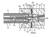
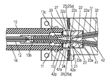
- FIG. 1 is a cross-sectional view showing the wire merging portion 20 and its periphery of the welding torch 1 of the present embodiment.
- FIG. 2 is an enlarged view of the welding torch 1 and shows the torch main body 10 and the wire joining portion 20.
- the welding torch 1 has a torch body portion 10 and a wire joining portion 20.
- a torch cable 30 is connected to the wire junction 20 by a cable connecting member 50 and a torch cable 40 is connected by a cable connecting member 60.
- the torch cables 30 and 40 are detachable from the cable connecting members 50 and 60, respectively.
- the torch cable 30 has a conduit tube 31 through which the welding wire 32 is inserted, and the rear end portion 30b of the torch cable 30 is connected to a wire feeding device 30c that feeds the welding wire 32.
- the tip portion 30 a of the torch cable 30 is connected to the cable connection member 50.
- the torch cable 40 has a conduit tube 41 through which the welding wire 42 is inserted, and the rear end portion 40 b of the torch cable 40 is connected to a wire feeding device 40 c that feeds the welding wire 42.
- the tip 40 a of the torch cable 40 is connected to the cable connection member 60.
- the wire feeding device 30c can perform forward feeding for feeding the welding wire 32 to the welding torch 1 and reverse feeding for pulling the welding wire 32 back from the welding torch 1.
- the wire feeding device 40c can feed the welding wire 42 to the welding torch 1. Forward feeding and reverse feeding back the welding wire 42 from the welding torch 1 can be performed.
- the conduit tubes 31 and 32 of the torch cables 30 and 40 pass through the centers of the cable connecting members 50 and 60 and are inserted into the wire junction 20.
- the conduit tubes 31 and 41 reach the inlet side wire guide 21 in the wire joining portion 20 and guide the welding wires 32 and 42 to the inlet side wire guide 21, respectively.
- the structure of the inlet side wire guide 21 will be described later.
- one of the welding wires 32 and 42 is led from the inlet side wire guide 21 of the wire joining portion 20 to the outlet side wire guide 11 provided in the torch main body portion 10, and the other is the inlet side wire.
- the welding wire 32 is guided to the outlet side wire guide 11, and the welding wire 42 remains in the inlet side wire guide 21.
- the tip of the welding wire 42 is located in the inlet side wire guide 21.
- the structure of the outlet side wire guide 11 will be described later.
- the welding wire 32 guided to the outlet side wire guide 11 of the torch main body 10 passes through the inner tube 12 in the torch main body 10 and is supplied from the welding tip at the tip of the welding torch 1 to the welding location.
- a voltage is supplied to the welding wire 32 from the welding tip, and an arc is generated between the workpiece and the welding wire 32 to weld the workpiece.
- FIG. 2 is an enlarged view of the welding torch 1 and shows the torch main body 10 and the wire joining portion 20.
- the inlet side wire guide 21 is provided with a wire passage 22 and a wire passage 23. Further, a wire passage 13 is provided in the outlet side wire guide 11.
- a wire detection space 24 is provided between the inlet side wire guide 21 and the outlet side wire guide 11.
- the wire passage 22 has a wire inlet 22 a facing the end of the conduit tube 31 and a wire outlet 22 b facing the wire detection space 24.
- the wire passage 23 has a wire inlet 23 a facing the end of the conduit tube 41 and a wire outlet 23 b facing the wire detection space 24.
- the wire passage 13 has a wire outlet 13 b facing the end of the inner tube 12 and a wire inlet 13 a facing the wire detection space 24.
- the wire inlets 22a, 23a, 13a have a conical shape so that the welding wires 32, 42 can be easily inserted.
- the wire inlet 22a is configured to receive the welding wire 32.
- the wire outlet 22b is configured such that the welding wire 32 exits.
- the welding wire 32 entering from the wire inlet 22a is configured to pass through the wire passage 22 and exit from the wire outlet 22b.
- the wire inlet 23a is configured to receive the welding wire 42.
- the wire outlet 23b is configured such that the welding wire 42 exits.
- the welding wire 42 entering from the wire inlet 23 a is configured to exit from the wire outlet 23 b through the wire passage 23.
- the wire inlet 13a is configured such that a portion 32a of the welding wire 32 exiting from the wire outlet 22b and a portion 42a of the welding wire 42 exiting from the wire outlet 23b enter.
- the wire outlet 13b is configured such that a portion 32a of the welding wire 32 and a portion 42a of the welding wire 42 exit.
- the wire detection space 24 is connected to the wire outlet 23b, the wire outlet 22b, and the wire inlet 13a so that the portion 32a of the welding wire 32 and the portion 42a of the welding wire 42 pass therethrough.
- the part 32a of the welding wire 32 passes through the path 32p, and the part 42a of the welding wire 42 passes through the path 42p.
- the paths 32p and 42p intersect at an intersection 13c in the wire passage 13.
- the wire passage 22 and the wire passage 23 are located radially about the intersection 13c. At the intersection 13c, collision occurs when both the welding wire 32 and the welding wire 42 are fed simultaneously. With this structure, the welding wires 32 and 42 are smoothly fed from the conduit tubes 31 and 41 to the inner tube 12 through the inlet side wire guide 21, the wire detection space 24, and the outlet side wire guide 11.
- the cable connection members 50 and 60 are respectively located on extension lines extending linearly from the wire passages 22 and 23.
- the cable connection members 50, 60 do not have to be positioned on an extension line extending linearly from the wire passages 22, 23, and the conduit tubes 31, 41 between the cable connection members 50, 60 and the inlet side wire guide 21 are used. May be bent.
- an irradiator 25 and a light receiver 26 are provided on the side surface of the wire detection space 24 of the wire junction 20.
- the irradiator 25 and the light receiver 26 constitute a wire detection device 25a.
- detection light L ⁇ b> 25 is emitted from the irradiator 25 toward the light receiver 26.
- the irradiator 25 and the light receiver 26 are provided facing each other so that the detection light L25 crosses both the position where the welding wire 32 passes and the position where the welding wire 42 passes.
- the position where the welding wires 32 and 42 pass is, for example, on an extension line extending linearly from the wire passages 22 and 23. Further, the position where the welding wire 32 and the welding wire 42 meet is in the wire passage 13 of the outlet side wire guide 11.
- the wire detection device 25a detects the presence or absence of the welding wires 32 and 42 in the wire detection space 24 that is in front of the joining position.
- the light receiver 26 detects the detection light from the irradiator 25. If at least one of the welding wire 32 and the welding wire 42 exists in the wire detection space 24, the light receiver 26 cannot detect the detection light from the irradiator 25, or the detection intensity decreases. Thereby, the wire detection device 25 a can detect the presence of the welding wire 32 or the welding wire 42 in the wire detection space 24.
- the detection light L25 of the wire detection device 25a is visible light or invisible light such as infrared rays.
- the wire detection device 25a uses a capacitor composed of a pair of electrodes facing the wire detection space 24 to statically place the wire detection space 24. The presence or absence of the welding wires 32 and 42 may be electrically detected by measuring the electric capacity.
- a gas inlet 27 is provided on the side surface of the wire detection space 24 of the wire joining portion 20.
- a gas inlet 27 is provided behind the welding wire 32.
- a gas passage 14 provided outside the outlet side wire guide 11 and outside the inner tube 12 is provided in the torch main body 10, and the gas passage 14 is connected to the wire detection space 24.
- the shield gas introduced from the gas inlet 27 is supplied to the welding location from the welding nozzle at the tip of the welding torch 1 via the wire detection space 24 and the gas passage 14.
- the main component of the shielding gas is, for example, carbon dioxide gas
- MAG Metal-Active-Gas
- the main component of the shielding gas is, for example, argon.
- 3 to 5 show the states of the welding wires 32 and 42 in the switching method of the welding wires 32 and 42 of the welding torch 1.
- the welding wire 42 is not passed through the torch cable 40, and the welding wire 32 is connected to the conduit tube 31 and the inlet side wire guide 21 of the torch cable 30 from the wire feeding device 30 c (see FIG. 1).
- a wire detection space 24 is fed through the wire passage 22.
- the wire detection device the irradiator 25 and the light receiver 26 detects the portion 32a of the welding wire 32 from the wire outlet 22b by the detection light L25, and detects the presence of the welding wire 32 in the wire detection space 24.
- the portion 32a of the welding wire 32 is further processed from the welding tip provided at the tip of the torch body 10 through the wire passage 13 and the inner tube 12 of the outlet side wire guide 11, that is, from the wire outlet 22b through the path 32p. It is fed to the welding point of the object and welding is performed.
- a shield gas is supplied from the gas inlet 27 of the wire joining portion 20 to the wire detection space 24 and passes through the gas passage 14 to the work spot from the welding nozzle provided at the tip of the torch body 10. Supplied.
- the welding wire 32 is switched to the welding wire 42.
- the welding wire 32 that has been welded is reversely fed away from the torch body 10 by a wire feeding device 30 c (see FIG. 1) to which the torch cable 30 is connected.
- the welding wire 32 is pulled back while detecting whether the welding wire 32 exists in the wire detection space 24 by the wire detection device 25a.
- the wire detection device 25a detects that the welding wire 32 does not exist in the wire detection space 24.
- the wire feeding device 30c stops reverse feeding of the welding wire 32.
- the welding wire 32 is preferably stopped when the tip of the welding wire 32 is positioned in the wire passage 22 of the inlet side wire guide 21.
- the tip of the welding wire 32 is stopped at a position retracted 3 mm from the wire detection space 24. Thereby, even when welding by the welding wire 32 is resumed, the welding wire 32 can be supplied to the torch main body 10 in a short time.
- the welding wire 42 is fed to the welding tip provided at the tip of the welding torch 1 as shown in FIG.
- the welding wire 32 and the welding wire 42 have the same diameter and different materials.
- the welding wire 42 is transferred to the wire feeding device 40 c (see FIG. 1) in a state where the tip of the welding wire 32 is positioned in the wire passage 22 of the inlet side wire guide 21.
- the wire is fed to the wire detection space 24 through the conduit tube 41 of the torch cable 40 and the wire passage 23 of the inlet side wire guide 21.
- the wire detection device detects the portion 42a of the welding wire 42 from the wire outlet 23b by the detection light L25, and detects the presence of the welding wire 32 in the wire detection space 24.
- the portion 42a of the welding wire 42 is further processed from the welding tip provided at the tip of the torch body 10 through the wire passage 13 and the inner tube 12 of the outlet side wire guide 11, that is, from the wire outlet 23b through the path 42p. It is fed to the welding point of the object and welding is performed.
- the shield gas is supplied from the gas inlet 27 of the wire joining portion 20 to the wire detection space 24, and is processed from the welding nozzle provided at the tip of the torch main body portion 10 through the gas passage 14. Supplied to the welding point of the object.
- the welding wire 42 is torched while confirming the welding wire 42 with the wire feeding device 40c (see FIG. 1) in the same manner as the pulling back of the welding wire 32 described above.
- the main body 10 is pulled back to the wire passage 23 of the inlet side wire guide 21.
- the tip of the welding wire 42 is stopped at a position retracted 3 mm from the wire detection space 24.
- the welding wire 42 can be supplied to the torch main body 10 in a short time.
- the welding wire 42 is pulled back to the wire passage 23, the welding wire 32 that has been waiting in the wire passage 22 is again fed to the torch main body 10 as shown in FIG. 2. Thereafter, each time the welding wire 32 and the welding wire 42 are switched, the state of FIG. 2 and the state of FIG. 5 are repeated.
- the wire passage 22 has a wire inlet 22a configured to receive the welding wire 32 and a wire outlet 22b configured to allow the welding wire 32 to exit.
- the wire passage 23 has a wire inlet 23a configured to receive the welding wire 42 and a wire outlet 23b configured to allow the welding wire 42 to exit.
- the wire passage 13 includes a wire inlet 13a configured to receive a portion 32a exiting from the wire outlet 22b of the welding wire 32 and a portion 42a exiting from the wire outlet 23b of the welding wire 42, and a portion 32a of the welding wire 32.
- a wire outlet 13b configured to exit from a portion 42a of the welding wire 42;
- the wire detection space 24 is configured to connect to the wire outlet 22b, the wire outlet 23b, and the wire inlet 13a so that the portion 32a of the welding wire 32 and the portion 42a of the welding wire 42 pass through.
- the wire detection device 25 a is configured to detect the portion 32 a of the welding wire 32 and the portion 42 a of the welding wire 42 in the wire detection space 24.
- the wire detection device 25a may include an irradiator 25 that irradiates the detection light L25 and a light receiver 26 that receives the detection light L25.
- the path 32p through which the part 32a of the welding wire 32 passes and the path 42p through which the part 42a of the welding wire 42 passes may intersect at an intersection 13c.
- the detection light L25 passes through positions closer to the wire outlets 22b and 23b than the intersection 13c and passes through the paths 32p and 42p.
- the conventional wire feeding system 502 disclosed in Patent Document 2 includes two wire detection devices 920A and 920B for detecting wires. If the wire feeding system 520 is provided in the welding apparatus 510 disclosed in Patent Document 1, the configuration of the welding apparatus becomes complicated.
- the distance of pulling back the welding wires 32, 42 to be fed back and the distance of refeeding can be minimized.
- the wires 32 and 42 can be switched in a short time.
- two different welding wires 32 and 42 are detected by one wire detection device 25a, the structure is simple.
- the welding wires 32 and 42 are fed / reversely fed, abrasion powder is generated at the outlet and the inlet of the wire passage and accumulates in the wire detection space 24, so that the detection performance of the wire detection device 25a is deteriorated.
- the wear powder of the welding wires 32 and 42 is likely to accumulate at the wire joining point of the wire passage 13, increasing the wire feeding load and lowering the wire feeding performance.
- the gas inlet 27 of the wire joining portion 20 is provided in the wire detection space 24, the wire detection space 24 and the outlet-side wire are always applied by blowing shield gas during welding. It is possible to keep the wire passage 13 of the guide 11 in a clean state free from wear powder of the welding wires 32 and 42.
- the wear powder is forcedly discharged from the tip of the torch by flowing compressed air to the gas inlet 27 during switching of the welding wires 32 and 42. Is possible.
Landscapes
- Engineering & Computer Science (AREA)
- Physics & Mathematics (AREA)
- Plasma & Fusion (AREA)
- Mechanical Engineering (AREA)
- Arc Welding In General (AREA)
Abstract
In the present invention, a first wire path (22) has a first wire entry port (22a) and a first wire exit port (22b). A second wire path (23) has a second wire entry port (23a) and a second wire exit port (23b). A third wire path (13) has a third wire entry port (13a) and a third wire exit port (13b). A wire detection space (24) is configured so as to be connected to the first and second wire exit ports (22b, 23b) and the third wire entry port (13a), and so that a first weld wire (32) and a second weld wire (42) pass through said wire detection space (24). Wire detection devices (25, 26) are configured so as to detect the first weld wire (32) and the second weld wire (42) inside the wire detection space (24). This welding torch (1) has a simple structure, and can switch between the weld wires (32, 42).
Description
本開示は、複数の種類の溶接ワイヤに対応した溶接トーチに関する。
This disclosure relates to a welding torch that supports a plurality of types of welding wires.
図6は、特許文献1に開示された従来のアーク溶接装置501の概略図である。アーク溶接装置501では、ワイヤ送給装置900が、溶接ワイヤ901をトーチケーブル902によって送給し、溶接ワイヤ903をトーチケーブル904によって送給し、溶接トーチ910に送給している。溶接トーチ910は、トーチケーブル902が接続された入口側通路911と、トーチケーブル904が接続された入口側通路912と、出口側通路913とを有する。入口側通路911と入口側通路912とは中継部914で合流し、出口側通路913とつながっている。ワイヤ送給装置900は、溶接ワイヤ901を溶接トーチ910に送給し、溶接ワイヤ903をトーチケーブル904内に待機させることで、溶接ワイヤ901を溶接トーチ910の先端にあるノズル口915から突出させている。
FIG. 6 is a schematic diagram of a conventional arc welding apparatus 501 disclosed in Patent Document 1. In the arc welding apparatus 501, the wire feeding device 900 feeds the welding wire 901 through the torch cable 902, feeds the welding wire 903 through the torch cable 904, and feeds it to the welding torch 910. The welding torch 910 has an inlet side passage 911 to which the torch cable 902 is connected, an inlet side passage 912 to which the torch cable 904 is connected, and an outlet side passage 913. The entrance-side passage 911 and the entrance-side passage 912 merge at the relay portion 914 and are connected to the exit-side passage 913. The wire feeding device 900 feeds the welding wire 901 to the welding torch 910 and makes the welding wire 903 stand by in the torch cable 904, thereby causing the welding wire 901 to protrude from the nozzle port 915 at the tip of the welding torch 910. ing.
図7は、特許文献2に開示された従来のワイヤ送給システム502の概略図である。ワイヤ送給システム502では、ワイヤ送給装置920Aが、スプール軸921Aを中心にワイヤリール922Aを回転させてワイヤ923Aを送給し、ワイヤ送給装置920Bが、スプール軸921Bを中心にワイヤリール922Bを回転させてワイヤ923Bを送給する。ワイヤ923Aは、コンジットチューブ940Aと送給案内口950Aと分岐導管950と送給案内口950Cとコンジットチューブ940とを通過して溶接トーチ930に送給される。ワイヤ923Bは、コンジットチューブ940Bと送給案内口950Bと分岐導管950と送給案内口950Cとコンジットチューブ940とを通過して溶接トーチ930に送給される。ワイヤ検出装置941Aにより検出されたワイヤ923Aの有無およびワイヤ検出装置941Bによるワイヤ923Bの有無に基づいて、ワイヤ923Aとワイヤ923Bとが切り替えられる。
FIG. 7 is a schematic diagram of a conventional wire feeding system 502 disclosed in Patent Document 2. In the wire feeding system 502, the wire feeding device 920A rotates the wire reel 922A about the spool shaft 921A to feed the wire 923A, and the wire feeding device 920B uses the wire reel 922B about the spool shaft 921B. Is rotated to feed the wire 923B. The wire 923A passes through the conduit tube 940A, the feed guide port 950A, the branch conduit 950, the feed guide port 950C, and the conduit tube 940 and is fed to the welding torch 930. The wire 923B passes through the conduit tube 940B, the feed guide port 950B, the branch conduit 950, the feed guide port 950C, and the conduit tube 940 and is fed to the welding torch 930. The wire 923A and the wire 923B are switched based on the presence / absence of the wire 923A detected by the wire detection device 941A and the presence / absence of the wire 923B by the wire detection device 941B.
溶接トーチは、第1から第3のワイヤ通路とワイヤ検出空間とワイヤ検出装置とを備える。第1のワイヤ通路は、第1の溶接ワイヤが入るように構成された第1のワイヤ入口と、第1の溶接ワイヤが出るように構成された第1のワイヤ出口とを有する。第2のワイヤ通路は、第2の溶接ワイヤが入るように構成された第2のワイヤ入口と、第2の溶接ワイヤが出るように構成された第2のワイヤ出口とを有する。第3のワイヤ通路は、第1の溶接ワイヤの第1のワイヤ出口から出た部分と第2の溶接ワイヤの第2のワイヤ出口から出た部分とが入るように構成された第3のワイヤ入口と、第1の溶接ワイヤの上記部分と第2の溶接ワイヤの上記部分とが出るように構成された第3のワイヤ出口とを有する。ワイヤ検出空間は、第1と第2のワイヤ出口と第3のワイヤ入口とにつながって第1の溶接ワイヤの上記部分と第2の溶接ワイヤの上記部分とが通るように構成されている。ワイヤ検出装置は、ワイヤ検出空間内で第1の溶接ワイヤの上記部分と第2の溶接ワイヤの上記部分とを検出するように構成されている。
The welding torch includes first to third wire passages, a wire detection space, and a wire detection device. The first wire passage has a first wire inlet configured to receive the first welding wire and a first wire outlet configured to exit the first welding wire. The second wire passage has a second wire inlet configured to receive a second welding wire and a second wire outlet configured to exit the second welding wire. The third wire passage is configured so that a portion of the first welding wire that exits from the first wire outlet and a portion of the second welding wire that exits from the second wire outlet enter. An inlet, and a third wire outlet configured to exit the portion of the first welding wire and the portion of the second welding wire. The wire detection space is configured to be connected to the first and second wire outlets and the third wire inlet and pass through the portion of the first welding wire and the portion of the second welding wire. The wire detection device is configured to detect the portion of the first welding wire and the portion of the second welding wire in the wire detection space.
この溶接トーチは、シンプルな構造で、溶接ワイヤを切り替えることができる。
This welding torch has a simple structure and can switch the welding wire.
図1は、本実施の形態の溶接トーチ1のワイヤ合流部20およびその周辺を示す断面図である。図2は溶接トーチ1の拡大図であり、トーチ本体部10およびワイヤ合流部20を示す。
FIG. 1 is a cross-sectional view showing the wire merging portion 20 and its periphery of the welding torch 1 of the present embodiment. FIG. 2 is an enlarged view of the welding torch 1 and shows the torch main body 10 and the wire joining portion 20.
図1に示すように、溶接トーチ1は、トーチ本体部10とワイヤ合流部20とを有する。ワイヤ合流部20には、トーチケーブル30がケーブル接続部材50によって接続されるとともに、トーチケーブル40がケーブル接続部材60によって接続される。トーチケーブル30、40は、ケーブル接続部材50、60に対してそれぞれ着脱可能である。
As shown in FIG. 1, the welding torch 1 has a torch body portion 10 and a wire joining portion 20. A torch cable 30 is connected to the wire junction 20 by a cable connecting member 50 and a torch cable 40 is connected by a cable connecting member 60. The torch cables 30 and 40 are detachable from the cable connecting members 50 and 60, respectively.
トーチケーブル30は、溶接ワイヤ32が挿通されるコンジットチューブ31を有し、トーチケーブル30の後端部30bは溶接ワイヤ32を送給するワイヤ送給装置30cに接続されている。トーチケーブル30の先端部30aはケーブル接続部材50に接続されている。トーチケーブル40は、溶接ワイヤ42が挿通されるコンジットチューブ41を有し、トーチケーブル40の後端部40bは溶接ワイヤ42を送給するワイヤ送給装置40cに接続されている。トーチケーブル40の先端部40aはケーブル接続部材60に接続されている。ワイヤ送給装置30cは溶接ワイヤ32を溶接トーチ1に送り出す正送と、溶接ワイヤ32を溶接トーチ1から引き戻す逆送とを行うことができ、ワイヤ送給装置40cは溶接ワイヤ42を溶接トーチ1に送り出す正送と、溶接ワイヤ42を溶接トーチ1から引き戻す逆送とを行うことができる。
The torch cable 30 has a conduit tube 31 through which the welding wire 32 is inserted, and the rear end portion 30b of the torch cable 30 is connected to a wire feeding device 30c that feeds the welding wire 32. The tip portion 30 a of the torch cable 30 is connected to the cable connection member 50. The torch cable 40 has a conduit tube 41 through which the welding wire 42 is inserted, and the rear end portion 40 b of the torch cable 40 is connected to a wire feeding device 40 c that feeds the welding wire 42. The tip 40 a of the torch cable 40 is connected to the cable connection member 60. The wire feeding device 30c can perform forward feeding for feeding the welding wire 32 to the welding torch 1 and reverse feeding for pulling the welding wire 32 back from the welding torch 1. The wire feeding device 40c can feed the welding wire 42 to the welding torch 1. Forward feeding and reverse feeding back the welding wire 42 from the welding torch 1 can be performed.
トーチケーブル30、40のコンジットチューブ31、32はケーブル接続部材50、60の中心を通って、ワイヤ合流部20の内部に挿入される。コンジットチューブ31、41は、ワイヤ合流部20内の入口側ワイヤガイド21に達し、溶接ワイヤ32、42を入口側ワイヤガイド21にそれぞれ導く。入口側ワイヤガイド21の構造については後述する。
The conduit tubes 31 and 32 of the torch cables 30 and 40 pass through the centers of the cable connecting members 50 and 60 and are inserted into the wire junction 20. The conduit tubes 31 and 41 reach the inlet side wire guide 21 in the wire joining portion 20 and guide the welding wires 32 and 42 to the inlet side wire guide 21, respectively. The structure of the inlet side wire guide 21 will be described later.
実際の溶接時には、ワイヤ合流部20の入口側ワイヤガイド21から、溶接ワイヤ32、42のうちの一方が、トーチ本体部10に設けられた出口側ワイヤガイド11に導かれ、他方は入口側ワイヤガイド21内に留まる。図1に示すように、本実施の形態では、溶接ワイヤ32が出口側ワイヤガイド11に導かれ、溶接ワイヤ42が入口側ワイヤガイド21内に留まっている。言い換えると、溶接ワイヤ42の先端が、入口側ワイヤガイド21内に位置している。出口側ワイヤガイド11の構造については後述する。
During actual welding, one of the welding wires 32 and 42 is led from the inlet side wire guide 21 of the wire joining portion 20 to the outlet side wire guide 11 provided in the torch main body portion 10, and the other is the inlet side wire. Stay in the guide 21. As shown in FIG. 1, in the present embodiment, the welding wire 32 is guided to the outlet side wire guide 11, and the welding wire 42 remains in the inlet side wire guide 21. In other words, the tip of the welding wire 42 is located in the inlet side wire guide 21. The structure of the outlet side wire guide 11 will be described later.
トーチ本体部10の出口側ワイヤガイド11に導かれた溶接ワイヤ32は、トーチ本体部10内のインナーチューブ12内を通って、溶接トーチ1の先端にある溶接チップから溶接箇所に供給される。溶接ワイヤ32が溶接箇所に供給された状態で、溶接ワイヤ32には溶接チップから電圧が供給され、加工物と溶接ワイヤ32との間にアークを発生させて加工物を溶接する。
The welding wire 32 guided to the outlet side wire guide 11 of the torch main body 10 passes through the inner tube 12 in the torch main body 10 and is supplied from the welding tip at the tip of the welding torch 1 to the welding location. In a state in which the welding wire 32 is supplied to the welding location, a voltage is supplied to the welding wire 32 from the welding tip, and an arc is generated between the workpiece and the welding wire 32 to weld the workpiece.
ワイヤ合流部20について、さらに具体的に説明する。図2は溶接トーチ1の拡大図であり、トーチ本体部10とワイヤ合流部20とを示す。入口側ワイヤガイド21には、ワイヤ通路22とワイヤ通路23とが設けられている。また、出口側ワイヤガイド11には、ワイヤ通路13が設けられている。また、入口側ワイヤガイド21と出口側ワイヤガイド11との間にはワイヤ検出空間24が設けられている。
The wire junction 20 will be described in more detail. FIG. 2 is an enlarged view of the welding torch 1 and shows the torch main body 10 and the wire joining portion 20. The inlet side wire guide 21 is provided with a wire passage 22 and a wire passage 23. Further, a wire passage 13 is provided in the outlet side wire guide 11. A wire detection space 24 is provided between the inlet side wire guide 21 and the outlet side wire guide 11.
ワイヤ通路22は、コンジットチューブ31の端部に対向するワイヤ入口22aと、ワイヤ検出空間24に面したワイヤ出口22bとを有する。ワイヤ通路23は、コンジットチューブ41の端部に対向するワイヤ入口23aと、ワイヤ検出空間24に面したワイヤ出口23bとを有する。ワイヤ通路13は、インナーチューブ12の端部に対向するワイヤ出口13bと、ワイヤ検出空間24に面したワイヤ入口13aとを有する。ワイヤ入口22a、23a、13aは、溶接ワイヤ32、42が挿入されやすいように円錐形状を有する。
The wire passage 22 has a wire inlet 22 a facing the end of the conduit tube 31 and a wire outlet 22 b facing the wire detection space 24. The wire passage 23 has a wire inlet 23 a facing the end of the conduit tube 41 and a wire outlet 23 b facing the wire detection space 24. The wire passage 13 has a wire outlet 13 b facing the end of the inner tube 12 and a wire inlet 13 a facing the wire detection space 24. The wire inlets 22a, 23a, 13a have a conical shape so that the welding wires 32, 42 can be easily inserted.
ワイヤ入口22aは溶接ワイヤ32が入るように構成されている。ワイヤ出口22bは溶接ワイヤ32が出るように構成されている。ワイヤ入口22aから入った溶接ワイヤ32はワイヤ通路22を通ってワイヤ出口22bから出るように構成されている。ワイヤ入口23aは溶接ワイヤ42が入るように構成されている。ワイヤ出口23bは溶接ワイヤ42が出るように構成されている。ワイヤ入口23aから入った溶接ワイヤ42はワイヤ通路23を通ってワイヤ出口23bから出るように構成されている。ワイヤ入口13aは、溶接ワイヤ32のワイヤ出口22bから出た部分32aと溶接ワイヤ42のワイヤ出口23bから出た部分42aとが入るように構成されている。ワイヤ出口13bは、溶接ワイヤ32の部分32aと溶接ワイヤ42の部分42aとが出るように構成されている。
The wire inlet 22a is configured to receive the welding wire 32. The wire outlet 22b is configured such that the welding wire 32 exits. The welding wire 32 entering from the wire inlet 22a is configured to pass through the wire passage 22 and exit from the wire outlet 22b. The wire inlet 23a is configured to receive the welding wire 42. The wire outlet 23b is configured such that the welding wire 42 exits. The welding wire 42 entering from the wire inlet 23 a is configured to exit from the wire outlet 23 b through the wire passage 23. The wire inlet 13a is configured such that a portion 32a of the welding wire 32 exiting from the wire outlet 22b and a portion 42a of the welding wire 42 exiting from the wire outlet 23b enter. The wire outlet 13b is configured such that a portion 32a of the welding wire 32 and a portion 42a of the welding wire 42 exit.
ワイヤ検出空間24はワイヤ出口23bとワイヤ出口22bとワイヤ入口13aとにつながって溶接ワイヤ32の部分32aと溶接ワイヤ42の部分42aとが通るように構成されている。
The wire detection space 24 is connected to the wire outlet 23b, the wire outlet 22b, and the wire inlet 13a so that the portion 32a of the welding wire 32 and the portion 42a of the welding wire 42 pass therethrough.
溶接ワイヤ32の部分32aは経路32pを通り、溶接ワイヤ42の部分42aは経路42pを通る。経路32p、42pはワイヤ通路13内の交点13cで交わっている。ワイヤ通路22およびワイヤ通路23は交点13cを中心に放射状に位置している。交点13cでは、溶接ワイヤ32および溶接ワイヤ42の両方を同時に送給したときに衝突する。この構造により、溶接ワイヤ32、42は、コンジットチューブ31、41から、入口側ワイヤガイド21とワイヤ検出空間24と出口側ワイヤガイド11とを経て、インナーチューブ12へスムーズに送給される。
The part 32a of the welding wire 32 passes through the path 32p, and the part 42a of the welding wire 42 passes through the path 42p. The paths 32p and 42p intersect at an intersection 13c in the wire passage 13. The wire passage 22 and the wire passage 23 are located radially about the intersection 13c. At the intersection 13c, collision occurs when both the welding wire 32 and the welding wire 42 are fed simultaneously. With this structure, the welding wires 32 and 42 are smoothly fed from the conduit tubes 31 and 41 to the inner tube 12 through the inlet side wire guide 21, the wire detection space 24, and the outlet side wire guide 11.
なお、本実施の形態では、ケーブル接続部材50、60はワイヤ通路22、23から直線的に延びる延長線上にそれぞれ位置している。しかし、ケーブル接続部材50、60は、ワイヤ通路22、23から直線的に延びる延長線上に位置する必要はなく、ケーブル接続部材50、60と入口側ワイヤガイド21との間のコンジットチューブ31、41が曲がっていても構わない。
In the present embodiment, the cable connection members 50 and 60 are respectively located on extension lines extending linearly from the wire passages 22 and 23. However, the cable connection members 50, 60 do not have to be positioned on an extension line extending linearly from the wire passages 22, 23, and the conduit tubes 31, 41 between the cable connection members 50, 60 and the inlet side wire guide 21 are used. May be bent.
さらに、ワイヤ合流部20のワイヤ検出空間24の側面には、照射器25と受光器26とが設けられている。照射器25と受光器26とはワイヤ検出装置25aを構成する。図2に示すように、照射器25から受光器26に向けて検出光L25が発射される。照射器25と受光器26とは、検出光L25が溶接ワイヤ32の通過する位置と溶接ワイヤ42の通過する位置との両方を横切るように互いに向かい合って設けられている。なお、溶接ワイヤ32、42の通過する位置とは、例えば、ワイヤ通路22、23から直線的に延びる延長線上にある。また、溶接ワイヤ32と溶接ワイヤ42とが合流する位置は、出口側ワイヤガイド11のワイヤ通路13内である。ワイヤ検出装置25aは、合流する位置よりも手前であるワイヤ検出空間24における溶接ワイヤ32、42の有無を検出している。
Furthermore, an irradiator 25 and a light receiver 26 are provided on the side surface of the wire detection space 24 of the wire junction 20. The irradiator 25 and the light receiver 26 constitute a wire detection device 25a. As shown in FIG. 2, detection light L <b> 25 is emitted from the irradiator 25 toward the light receiver 26. The irradiator 25 and the light receiver 26 are provided facing each other so that the detection light L25 crosses both the position where the welding wire 32 passes and the position where the welding wire 42 passes. The position where the welding wires 32 and 42 pass is, for example, on an extension line extending linearly from the wire passages 22 and 23. Further, the position where the welding wire 32 and the welding wire 42 meet is in the wire passage 13 of the outlet side wire guide 11. The wire detection device 25a detects the presence or absence of the welding wires 32 and 42 in the wire detection space 24 that is in front of the joining position.
溶接ワイヤ32および溶接ワイヤ42がワイヤ検出空間24に存在していなければ、受光器26は、照射器25からの検出光を検出する。溶接ワイヤ32と溶接ワイヤ42のうちの少なくとも1つがワイヤ検出空間24に存在していれば、受光器26は、照射器25からの検出光を検出できない、もしくは、検出強度が低下する。これにより、ワイヤ検出装置25aはワイヤ検出空間24における溶接ワイヤ32または溶接ワイヤ42の存在を検出することができる。ワイヤ検出装置25aの検出光L25は、可視光、あるいは、赤外線などの不可視光である。また、溶接ワイヤ32、42が鉄などの磁性材料を主成分とする場合は、ワイヤ検出装置25aは、ワイヤ検出空間24を間に対向する一対の電極よりなるコンデンサによって、ワイヤ検出空間24の静電容量を測定して溶接ワイヤ32、42の有無を電気的に検出してもよい。
If the welding wire 32 and the welding wire 42 do not exist in the wire detection space 24, the light receiver 26 detects the detection light from the irradiator 25. If at least one of the welding wire 32 and the welding wire 42 exists in the wire detection space 24, the light receiver 26 cannot detect the detection light from the irradiator 25, or the detection intensity decreases. Thereby, the wire detection device 25 a can detect the presence of the welding wire 32 or the welding wire 42 in the wire detection space 24. The detection light L25 of the wire detection device 25a is visible light or invisible light such as infrared rays. In addition, when the welding wires 32 and 42 are mainly composed of a magnetic material such as iron, the wire detection device 25a uses a capacitor composed of a pair of electrodes facing the wire detection space 24 to statically place the wire detection space 24. The presence or absence of the welding wires 32 and 42 may be electrically detected by measuring the electric capacity.
図2に示すように、ワイヤ合流部20のワイヤ検出空間24の側面にはガス入口27が設けられている。図2では、溶接ワイヤ32の奥にガス入口27が設けられている。トーチ本体部10内には、出口側ワイヤガイド11の外側およびインナーチューブ12の外側に設けられたガス通路14が設けられており、ガス通路14はワイヤ検出空間24と接続されている。ガス入口27から導入されたシールドガスは、ワイヤ検出空間24とガス通路14とを経由して、溶接トーチ1の先端の溶接ノズルから溶接箇所に供給される。MIG(Metal-Inert-Gas)溶接では、シールドガスの主成分は、例えば、炭酸ガスであり、MAG(Metal-Active-Gas)溶接では、シールドガスの主成分は、例えば、アルゴンである。
As shown in FIG. 2, a gas inlet 27 is provided on the side surface of the wire detection space 24 of the wire joining portion 20. In FIG. 2, a gas inlet 27 is provided behind the welding wire 32. A gas passage 14 provided outside the outlet side wire guide 11 and outside the inner tube 12 is provided in the torch main body 10, and the gas passage 14 is connected to the wire detection space 24. The shield gas introduced from the gas inlet 27 is supplied to the welding location from the welding nozzle at the tip of the welding torch 1 via the wire detection space 24 and the gas passage 14. In MIG (Metal-Inert-Gas) welding, the main component of the shielding gas is, for example, carbon dioxide gas, and in MAG (Metal-Active-Gas) welding, the main component of the shielding gas is, for example, argon.
次に、本実施の形態の溶接トーチ1を用いた溶接ワイヤの切替方法について、説明する。図3から図5は溶接トーチ1の溶接ワイヤ32、42の切替方法における溶接ワイヤ32、42の状態を示す。
Next, a welding wire switching method using the welding torch 1 of the present embodiment will be described. 3 to 5 show the states of the welding wires 32 and 42 in the switching method of the welding wires 32 and 42 of the welding torch 1.
まず、図3に示すように、溶接ワイヤ42をトーチケーブル40には通さず、溶接ワイヤ32をワイヤ送給装置30c(図1参照)よりトーチケーブル30のコンジットチューブ31及び入口側ワイヤガイド21のワイヤ通路22を通ってワイヤ検出空間24に送給する。これにより、ワイヤ検出装置(照射器25および受光器26)は溶接ワイヤ32のワイヤ出口22bから出た部分32aを検出光L25によって検出して、ワイヤ検出空間24における溶接ワイヤ32の存在を検出する。溶接ワイヤ32の部分32aはさらに、出口側ワイヤガイド11のワイヤ通路13およびインナーチューブ12を通って、すなわちワイヤ出口22bから経路32pを通ってトーチ本体部10の先端に設けられた溶接チップから加工物の溶接箇所に送給され、溶接が行われる。
First, as shown in FIG. 3, the welding wire 42 is not passed through the torch cable 40, and the welding wire 32 is connected to the conduit tube 31 and the inlet side wire guide 21 of the torch cable 30 from the wire feeding device 30 c (see FIG. 1). A wire detection space 24 is fed through the wire passage 22. As a result, the wire detection device (the irradiator 25 and the light receiver 26) detects the portion 32a of the welding wire 32 from the wire outlet 22b by the detection light L25, and detects the presence of the welding wire 32 in the wire detection space 24. . The portion 32a of the welding wire 32 is further processed from the welding tip provided at the tip of the torch body 10 through the wire passage 13 and the inner tube 12 of the outlet side wire guide 11, that is, from the wire outlet 22b through the path 32p. It is fed to the welding point of the object and welding is performed.
なお、溶接中は、シールドガスがワイヤ合流部20のガス入口27からワイヤ検出空間24に供給され、ガス通路14通ってトーチ本体部10の先端に設けられた溶接ノズルから加工物の溶接箇所に供給される。
During welding, a shield gas is supplied from the gas inlet 27 of the wire joining portion 20 to the wire detection space 24 and passes through the gas passage 14 to the work spot from the welding nozzle provided at the tip of the torch body 10. Supplied.
次に、溶接ワイヤ32を溶接ワイヤ42へ切り替える。図4に示すように、溶接を行った溶接ワイヤ32をトーチケーブル30が接続されたワイヤ送給装置30c(図1参照)によってトーチ本体部10からから離れるように逆送して引き戻す。このとき、ワイヤ検出装置25aによって、溶接ワイヤ32がワイヤ検出空間24に存在するかどうかを検出しながら溶接ワイヤ32を引き戻す。溶接ワイヤ32の先端がワイヤ検出空間24を通過して溶接ワイヤ32の部分32aが無くなると、ワイヤ検出装置25aは溶接ワイヤ32がワイヤ検出空間24に存在しないことを検出する。このとき、ワイヤ送給装置30cは溶接ワイヤ32の逆送を停止する。溶接ワイヤ32は、溶接ワイヤ32の先端が入口側ワイヤガイド21のワイヤ通路22内に位置するところで停止することが好ましい。例えば、溶接ワイヤ32の先端をワイヤ検出空間24から3mm後退した位置に停止させる。これにより、溶接ワイヤ32による溶接を再開するときも、短時間で溶接ワイヤ32をトーチ本体部10に供給できる。
Next, the welding wire 32 is switched to the welding wire 42. As shown in FIG. 4, the welding wire 32 that has been welded is reversely fed away from the torch body 10 by a wire feeding device 30 c (see FIG. 1) to which the torch cable 30 is connected. At this time, the welding wire 32 is pulled back while detecting whether the welding wire 32 exists in the wire detection space 24 by the wire detection device 25a. When the tip of the welding wire 32 passes through the wire detection space 24 and the portion 32a of the welding wire 32 disappears, the wire detection device 25a detects that the welding wire 32 does not exist in the wire detection space 24. At this time, the wire feeding device 30c stops reverse feeding of the welding wire 32. The welding wire 32 is preferably stopped when the tip of the welding wire 32 is positioned in the wire passage 22 of the inlet side wire guide 21. For example, the tip of the welding wire 32 is stopped at a position retracted 3 mm from the wire detection space 24. Thereby, even when welding by the welding wire 32 is resumed, the welding wire 32 can be supplied to the torch main body 10 in a short time.
次に、前述した溶接ワイヤ32の送給と同様に、図5に示すように、溶接ワイヤ42を溶接トーチ1の先端に設けられた溶接チップまで送給し、溶接を行う。実施の形態では、溶接ワイヤ32と溶接ワイヤ42とは、直径が同じで材質が異なる。具体的には、図5に示すように、溶接ワイヤ32の先端が入口側ワイヤガイド21のワイヤ通路22内に位置している状態で、溶接ワイヤ42をワイヤ送給装置40c(図1参照)よりトーチケーブル40のコンジットチューブ41及び入口側ワイヤガイド21のワイヤ通路23を通ってワイヤ検出空間24に送給する。これにより、ワイヤ検出装置(照射器25および受光器26)は溶接ワイヤ42のワイヤ出口23bから出た部分42aを検出光L25によって検出して、ワイヤ検出空間24における溶接ワイヤ32の存在を検出する。溶接ワイヤ42の部分42aはさらに、出口側ワイヤガイド11のワイヤ通路13およびインナーチューブ12を通って、すなわちワイヤ出口23bから経路42pを通ってトーチ本体部10の先端に設けられた溶接チップから加工物の溶接箇所に送給され、溶接が行われる。
Next, similarly to the feeding of the welding wire 32 described above, the welding wire 42 is fed to the welding tip provided at the tip of the welding torch 1 as shown in FIG. In the embodiment, the welding wire 32 and the welding wire 42 have the same diameter and different materials. Specifically, as shown in FIG. 5, the welding wire 42 is transferred to the wire feeding device 40 c (see FIG. 1) in a state where the tip of the welding wire 32 is positioned in the wire passage 22 of the inlet side wire guide 21. Further, the wire is fed to the wire detection space 24 through the conduit tube 41 of the torch cable 40 and the wire passage 23 of the inlet side wire guide 21. Thereby, the wire detection device (the irradiator 25 and the light receiver 26) detects the portion 42a of the welding wire 42 from the wire outlet 23b by the detection light L25, and detects the presence of the welding wire 32 in the wire detection space 24. . The portion 42a of the welding wire 42 is further processed from the welding tip provided at the tip of the torch body 10 through the wire passage 13 and the inner tube 12 of the outlet side wire guide 11, that is, from the wire outlet 23b through the path 42p. It is fed to the welding point of the object and welding is performed.
なお、溶接ワイヤ32による溶接中も、シールドガスがワイヤ合流部20のガス入口27からワイヤ検出空間24に供給され、ガス通路14を通ってトーチ本体部10の先端に設けられた溶接ノズルから加工物の溶接箇所に供給される。
Even during welding with the welding wire 32, the shield gas is supplied from the gas inlet 27 of the wire joining portion 20 to the wire detection space 24, and is processed from the welding nozzle provided at the tip of the torch main body portion 10 through the gas passage 14. Supplied to the welding point of the object.
再度、溶接ワイヤ42から溶接ワイヤ32へ切り替える場合は、前述した溶接ワイヤ32の引き戻しと同じように、ワイヤ送給装置40c(図1参照)で溶接ワイヤ42を確認しながら、溶接ワイヤ42をトーチ本体部10から入口側ワイヤガイド21のワイヤ通路23まで引き戻す。例えば、溶接ワイヤ42の先端を、ワイヤ検出空間24から3mm後退した位置に停止させる。これにより、溶接ワイヤ42による溶接を再開するときも、短時間で溶接ワイヤ42をトーチ本体部10に供給できる。溶接ワイヤ42がワイヤ通路23まで引き戻されたら、図2に示すように、ワイヤ通路22で待機していた溶接ワイヤ32を再度、トーチ本体部10へ送給する。その後は、溶接ワイヤ32と溶接ワイヤ42を切り替えるたびに、図2の状態と図5の状態が繰り返される。
When switching from the welding wire 42 to the welding wire 32 again, the welding wire 42 is torched while confirming the welding wire 42 with the wire feeding device 40c (see FIG. 1) in the same manner as the pulling back of the welding wire 32 described above. The main body 10 is pulled back to the wire passage 23 of the inlet side wire guide 21. For example, the tip of the welding wire 42 is stopped at a position retracted 3 mm from the wire detection space 24. Thereby, even when welding with the welding wire 42 is resumed, the welding wire 42 can be supplied to the torch main body 10 in a short time. When the welding wire 42 is pulled back to the wire passage 23, the welding wire 32 that has been waiting in the wire passage 22 is again fed to the torch main body 10 as shown in FIG. 2. Thereafter, each time the welding wire 32 and the welding wire 42 are switched, the state of FIG. 2 and the state of FIG. 5 are repeated.
上述のように、ワイヤ通路22は、溶接ワイヤ32が入るように構成されたワイヤ入口22aと、溶接ワイヤ32が出るように構成されたワイヤ出口22bとを有する。ワイヤ通路23は、溶接ワイヤ42が入るように構成されたワイヤ入口23aと、溶接ワイヤ42が出るように構成されたワイヤ出口23bとを有する。ワイヤ通路13は、溶接ワイヤ32のワイヤ出口22bから出た部分32aと溶接ワイヤ42のワイヤ出口23bから出た部分42aとが入るように構成されたワイヤ入口13aと、溶接ワイヤ32の部分32aと溶接ワイヤ42の部分42aとが出るように構成されたワイヤ出口13bとを有する。ワイヤ検出空間24は、ワイヤ出口22bとワイヤ出口23bとワイヤ入口13aとにつながって溶接ワイヤ32の部分32aと溶接ワイヤ42の部分42aとが通るように構成されている。ワイヤ検出装置25aは、ワイヤ検出空間24内で溶接ワイヤ32の部分32aと溶接ワイヤ42の部分42aとを検出するように構成されている。
As described above, the wire passage 22 has a wire inlet 22a configured to receive the welding wire 32 and a wire outlet 22b configured to allow the welding wire 32 to exit. The wire passage 23 has a wire inlet 23a configured to receive the welding wire 42 and a wire outlet 23b configured to allow the welding wire 42 to exit. The wire passage 13 includes a wire inlet 13a configured to receive a portion 32a exiting from the wire outlet 22b of the welding wire 32 and a portion 42a exiting from the wire outlet 23b of the welding wire 42, and a portion 32a of the welding wire 32. A wire outlet 13b configured to exit from a portion 42a of the welding wire 42; The wire detection space 24 is configured to connect to the wire outlet 22b, the wire outlet 23b, and the wire inlet 13a so that the portion 32a of the welding wire 32 and the portion 42a of the welding wire 42 pass through. The wire detection device 25 a is configured to detect the portion 32 a of the welding wire 32 and the portion 42 a of the welding wire 42 in the wire detection space 24.
ワイヤ検出装置25aは、検出光L25を照射する照射器25と、検出光L25を受光する受光器26とを有していてもよい。
The wire detection device 25a may include an irradiator 25 that irradiates the detection light L25 and a light receiver 26 that receives the detection light L25.
溶接ワイヤ32の部分32aが通る経路32pと溶接ワイヤ42の部分42aが通る経路42pとは交点13cで交わっていてもよい。この場合に、検出光L25は、交点13cよりもワイヤ出口22b、23bに近い位置を通過し、かつ経路32p、42pを通過する。
The path 32p through which the part 32a of the welding wire 32 passes and the path 42p through which the part 42a of the welding wire 42 passes may intersect at an intersection 13c. In this case, the detection light L25 passes through positions closer to the wire outlets 22b and 23b than the intersection 13c and passes through the paths 32p and 42p.
特許文献2に開示された従来のワイヤ送給システム502では、ワイヤの検出のために2つのワイヤ検出装置920A、920Bを備える。ワイヤ送給システム520を特許文献1に開示されている溶接装置510に設けると溶接装置の構成が複雑になる。
The conventional wire feeding system 502 disclosed in Patent Document 2 includes two wire detection devices 920A and 920B for detecting wires. If the wire feeding system 520 is provided in the welding apparatus 510 disclosed in Patent Document 1, the configuration of the welding apparatus becomes complicated.
本実施の形態の溶接トーチ1では、異なる2つの溶接ワイヤ32、42の切り替えにおいて、逆送する溶接ワイヤ32、42の引き戻しの距離や再度送給する距離を最小限に抑えることができ、溶接ワイヤ32、42を短時間で切り替えることができる。また、異なる2つの溶接ワイヤ32、42を1つのワイヤ検出装置25aで検出するため、構造がシンプルである。
In the welding torch 1 of the present embodiment, when switching between two different welding wires 32, 42, the distance of pulling back the welding wires 32, 42 to be fed back and the distance of refeeding can be minimized. The wires 32 and 42 can be switched in a short time. Moreover, since two different welding wires 32 and 42 are detected by one wire detection device 25a, the structure is simple.
また、溶接ワイヤ32、42を送給/逆送するとワイヤ通路の出口や入口において摩耗粉が発生し、ワイヤ検出空間24に堆積し、ワイヤ検出装置25aの検出性能が低下する。また溶接ワイヤ32、42の摩耗粉はワイヤ通路13のワイヤ合流地点に堆積しやすく、ワイヤ送給の負荷が増加し、ワイヤ送給性能が低下する。しかし、本実施の形態の溶接トーチ1は、ワイヤ合流部20のガス入口27がワイヤ検出空間24に設けられているため、溶接時のシールドガスの吹きつけにより常にワイヤ検出空間24及び出口側ワイヤガイド11のワイヤ通路13を溶接ワイヤ32、42の摩耗粉の無いきれいな状態に保つことが可能である。さらに、溶接ワイヤ32、42の著しく多くの摩耗粉が発生する場合には、溶接ワイヤ32、42の切り替え中にガス入口27に圧縮空気を流して強制的にトーチ先端より摩耗粉を排出することが可能である。
Further, when the welding wires 32 and 42 are fed / reversely fed, abrasion powder is generated at the outlet and the inlet of the wire passage and accumulates in the wire detection space 24, so that the detection performance of the wire detection device 25a is deteriorated. In addition, the wear powder of the welding wires 32 and 42 is likely to accumulate at the wire joining point of the wire passage 13, increasing the wire feeding load and lowering the wire feeding performance. However, in the welding torch 1 of the present embodiment, since the gas inlet 27 of the wire joining portion 20 is provided in the wire detection space 24, the wire detection space 24 and the outlet-side wire are always applied by blowing shield gas during welding. It is possible to keep the wire passage 13 of the guide 11 in a clean state free from wear powder of the welding wires 32 and 42. Further, when a significant amount of wear powder is generated on the welding wires 32 and 42, the wear powder is forcedly discharged from the tip of the torch by flowing compressed air to the gas inlet 27 during switching of the welding wires 32 and 42. Is possible.
1 溶接トーチ
10 トーチ本体部
11 出口側ワイヤガイド
12 インナーチューブ
13 ワイヤ通路(第3のワイヤ通路)
13a ワイヤ入口(第3のワイヤ入口)
13b ワイヤ出口(第3のワイヤ出口)
13c 交点
14 ガス通路
20 ワイヤ合流部
22 ワイヤ通路(第1のワイヤ通路)
22a ワイヤ入口(第1のワイヤ入口)
22b ワイヤ出口(第1のワイヤ出口)
23 ワイヤ通路(第2のワイヤ通路)
23a ワイヤ入口(第2のワイヤ入口)
23b ワイヤ出口(第2のワイヤ出口)
21 入口側ワイヤガイド
24 ワイヤ検出空間
25 照射器
26 受光器
27 ガス入口
30,40 トーチケーブル
31,41 コンジットチューブ
32 溶接ワイヤ(第1の溶接ワイヤ)
32p 経路(第1の経路)
42 溶接ワイヤ(第2の溶接ワイヤ)
42p 経路(第2の経路)
50,60 ケーブル接続部材 DESCRIPTION OF SYMBOLS 1Welding torch 10 Torch main-body part 11 Outlet side wire guide 12 Inner tube 13 Wire channel | path (3rd wire channel | path)
13a Wire inlet (third wire inlet)
13b Wire outlet (third wire outlet)
13c Intersection 14 Gas passage 20 Wire junction 22 Wire passage (first wire passage)
22a Wire inlet (first wire inlet)
22b Wire outlet (first wire outlet)
23 Wire passage (second wire passage)
23a Wire inlet (second wire inlet)
23b Wire outlet (second wire outlet)
21 Inletside wire guide 24 Wire detection space 25 Irradiator 26 Light receiver 27 Gas inlet 30, 40 Torch cable 31, 41 Conduit tube 32 Welding wire (first welding wire)
32p route (first route)
42 Welding wire (second welding wire)
42p route (second route)
50, 60 Cable connection member
10 トーチ本体部
11 出口側ワイヤガイド
12 インナーチューブ
13 ワイヤ通路(第3のワイヤ通路)
13a ワイヤ入口(第3のワイヤ入口)
13b ワイヤ出口(第3のワイヤ出口)
13c 交点
14 ガス通路
20 ワイヤ合流部
22 ワイヤ通路(第1のワイヤ通路)
22a ワイヤ入口(第1のワイヤ入口)
22b ワイヤ出口(第1のワイヤ出口)
23 ワイヤ通路(第2のワイヤ通路)
23a ワイヤ入口(第2のワイヤ入口)
23b ワイヤ出口(第2のワイヤ出口)
21 入口側ワイヤガイド
24 ワイヤ検出空間
25 照射器
26 受光器
27 ガス入口
30,40 トーチケーブル
31,41 コンジットチューブ
32 溶接ワイヤ(第1の溶接ワイヤ)
32p 経路(第1の経路)
42 溶接ワイヤ(第2の溶接ワイヤ)
42p 経路(第2の経路)
50,60 ケーブル接続部材 DESCRIPTION OF SYMBOLS 1
13a Wire inlet (third wire inlet)
13b Wire outlet (third wire outlet)
22a Wire inlet (first wire inlet)
22b Wire outlet (first wire outlet)
23 Wire passage (second wire passage)
23a Wire inlet (second wire inlet)
23b Wire outlet (second wire outlet)
21 Inlet
32p route (first route)
42 Welding wire (second welding wire)
42p route (second route)
50, 60 Cable connection member
Claims (4)
- 第1の溶接ワイヤが入るように構成された第1のワイヤ入口と、前記第1の溶接ワイヤが出るように構成された第1のワイヤ出口とを有する第1のワイヤ通路と、
第2の溶接ワイヤが入るように構成された第2のワイヤ入口と、前記第2の溶接ワイヤが出るように構成された第2のワイヤ出口とを有する第2のワイヤ通路と、
前記第1の溶接ワイヤの前記第1のワイヤ出口から出た部分と前記第2の溶接ワイヤの前記第2のワイヤ出口から出た部分とが入るように構成された第3のワイヤ入口と、前記第1の溶接ワイヤの前記部分と前記第2の溶接ワイヤの前記部分とが出るように構成された第3のワイヤ出口とを有する第3のワイヤ通路と、
前記第1のワイヤ出口と前記第2のワイヤ出口と前記第3のワイヤ入口とにつながって前記第1の溶接ワイヤの前記部分と前記第2の溶接ワイヤの前記部分とが通るように構成されたワイヤ検出空間と、
前記ワイヤ検出空間内で前記第1の溶接ワイヤの前記部分と前記第2の溶接ワイヤの前記部分とを検出するように構成されたワイヤ検出装置と、
を備えた溶接トーチ。 A first wire passage having a first wire inlet configured to receive a first welding wire and a first wire outlet configured to exit the first welding wire;
A second wire passage having a second wire inlet configured to receive a second welding wire and a second wire outlet configured to exit the second welding wire;
A third wire inlet configured to receive a portion of the first welding wire exiting from the first wire outlet and a portion of the second welding wire exiting from the second wire outlet; A third wire passage having a third wire outlet configured to exit the portion of the first welding wire and the portion of the second welding wire;
The portion of the first welding wire and the portion of the second welding wire pass through the first wire outlet, the second wire outlet, and the third wire inlet. Wire detection space,
A wire detection device configured to detect the portion of the first welding wire and the portion of the second welding wire in the wire detection space;
Welding torch with - 前記ワイヤ検出装置は、
検出光を照射する照射器と
前記検出光を受光する受光器と、
を有する、請求項1に記載の溶接トーチ。 The wire detection device
An irradiator for irradiating detection light; a light receiver for receiving the detection light;
The welding torch according to claim 1, comprising: - 前記第1の溶接ワイヤの前記部分が通る経路と前記第2の溶接ワイヤの前記部分が通る経路とは交点で交わっており、
前記検出光は、前記交点よりも前記第1のワイヤ出口および前記第2のワイヤ出口に近い位置を通過し、かつ前記第1の溶接ワイヤの前記部分が通る前記経路と前記第2の溶接ワイヤの前記部分が通る前記経路とを通過する、請求項2に記載の溶接トーチ。 The path through which the portion of the first welding wire passes and the path through which the portion of the second welding wire crosses at an intersection,
The detection light passes through a position closer to the first wire outlet and the second wire outlet than the intersection, and the path through which the portion of the first welding wire passes and the second welding wire The welding torch of claim 2, wherein the welding torch passes through the path through which the portion of the. - 前記ワイヤ検出空間に設けられてシールドガスが供給されるガス入口をさらに備えた、請求項1から3のいずれか一項に記載の溶接トーチ。 The welding torch according to any one of claims 1 to 3, further comprising a gas inlet provided in the wire detection space and supplied with a shielding gas.
Priority Applications (4)
| Application Number | Priority Date | Filing Date | Title |
|---|---|---|---|
| JP2017546394A JP6846620B2 (en) | 2015-10-23 | 2016-09-20 | Welding torch |
| EP16857075.2A EP3366404B1 (en) | 2015-10-23 | 2016-09-20 | Welding torch |
| US15/743,445 US10688586B2 (en) | 2015-10-23 | 2016-09-20 | Welding torch |
| CN201680045620.4A CN107848056B (en) | 2015-10-23 | 2016-09-20 | Welding torch |
Applications Claiming Priority (2)
| Application Number | Priority Date | Filing Date | Title |
|---|---|---|---|
| JP2015-208530 | 2015-10-23 | ||
| JP2015208530 | 2015-10-23 |
Publications (1)
| Publication Number | Publication Date |
|---|---|
| WO2017068752A1 true WO2017068752A1 (en) | 2017-04-27 |
Family
ID=58556870
Family Applications (1)
| Application Number | Title | Priority Date | Filing Date |
|---|---|---|---|
| PCT/JP2016/004277 WO2017068752A1 (en) | 2015-10-23 | 2016-09-20 | Welding torch |
Country Status (5)
| Country | Link |
|---|---|
| US (1) | US10688586B2 (en) |
| EP (1) | EP3366404B1 (en) |
| JP (1) | JP6846620B2 (en) |
| CN (1) | CN107848056B (en) |
| WO (1) | WO2017068752A1 (en) |
Cited By (1)
| Publication number | Priority date | Publication date | Assignee | Title |
|---|---|---|---|---|
| EP3546104B1 (en) * | 2018-03-28 | 2023-04-26 | Purem GmbH | Welding wire supply system |
Families Citing this family (3)
| Publication number | Priority date | Publication date | Assignee | Title |
|---|---|---|---|---|
| DE102018114754A1 (en) * | 2018-03-28 | 2019-10-02 | Eberspächer Exhaust Technology GmbH & Co. KG | Schweißdrahtzuführsystem |
| CN111390347A (en) * | 2020-03-09 | 2020-07-10 | 上海交通大学 | Continuous-feeding double-welding-wire molten drop alternative transition control device and method |
| CN114799435A (en) * | 2022-05-09 | 2022-07-29 | 唐山松下产业机器有限公司 | Contact tube assembly and welding gun |
Citations (5)
| Publication number | Priority date | Publication date | Assignee | Title |
|---|---|---|---|---|
| JPS57100870A (en) * | 1980-12-15 | 1982-06-23 | Kobe Steel Ltd | Feed method for welding wire |
| US6066833A (en) * | 1998-07-29 | 2000-05-23 | Howard Industries | Apparatus and method for selectively changing welding wire |
| JP2006102776A (en) * | 2004-10-05 | 2006-04-20 | Fanuc Ltd | Arc welding apparatus and arc welding robot system |
| JP2007000904A (en) * | 2005-06-24 | 2007-01-11 | Matsumoto Kikai Kk | Device for automatically changing-over welding wire |
| KR101595282B1 (en) * | 2014-11-13 | 2016-02-19 | 대우조선해양 주식회사 | A changing apparatus of welding wires |
Family Cites Families (35)
| Publication number | Priority date | Publication date | Assignee | Title |
|---|---|---|---|---|
| US3857091A (en) * | 1972-07-24 | 1974-12-24 | Continental Copper & Steel Ind | Apparatus having ultrasonic transducer for detecting cable dielectric faults |
| US4079231A (en) * | 1976-03-30 | 1978-03-14 | Union Carbide Corporation | Touchwork system for a MIG arc welding apparatus |
| JPS56168967A (en) | 1980-05-30 | 1981-12-25 | Mitsubishi Electric Corp | Wire feeder for welding |
| JPH01170593A (en) * | 1987-12-25 | 1989-07-05 | Kawasaki Steel Corp | Welding wire feeding device |
| JPH02123388U (en) | 1989-03-17 | 1990-10-11 | ||
| US5060395A (en) * | 1990-02-15 | 1991-10-29 | Artos Engineering Company | Closed loop wire feeding and measuring apparatus and method of operating same |
| US6247664B1 (en) * | 1999-06-25 | 2001-06-19 | Siecor Operations, Llc | Reel monitor devices and methods of using the same |
| AT413954B (en) | 2000-11-02 | 2006-07-15 | Fronius Int Gmbh | DETECTION ELEMENT FOR A WELDING DEVICE |
| US6984806B2 (en) * | 2002-07-23 | 2006-01-10 | Illinois Tool Works Inc. | Method and apparatus for retracting and advancing a welding wire |
| US6977357B2 (en) * | 2003-07-09 | 2005-12-20 | Lincoln Global, Inc. | Welding wire positioning system |
| US9579742B2 (en) * | 2006-01-09 | 2017-02-28 | Lincoln Global, Inc. | Series arc welder |
| US8225977B2 (en) * | 2004-03-08 | 2012-07-24 | Lincoln Global, Inc. | Wire feeder with run-in control |
| JP2005254247A (en) * | 2004-03-09 | 2005-09-22 | Matsushita Electric Ind Co Ltd | Welding equipment |
| US20060070987A1 (en) * | 2004-09-30 | 2006-04-06 | Lincoln Global, Inc. | Monitoring device for welding wire supply |
| JP2006198628A (en) | 2005-01-18 | 2006-08-03 | Fanuc Ltd | Arc welding equipment, and arc robot system |
| JP2006281284A (en) | 2005-04-01 | 2006-10-19 | Sango Co Ltd | Welding equipment |
| US8581146B2 (en) * | 2008-10-22 | 2013-11-12 | Lincoln Global, Inc. | Automatic wire feeding system |
| US9321116B2 (en) * | 2009-03-05 | 2016-04-26 | United Technologies Corporation | Cold metal transfer gas metal arc welding apparatus and method of operation |
| JP5342280B2 (en) * | 2009-03-16 | 2013-11-13 | 株式会社神戸製鋼所 | Tandem pulse arc welding control apparatus and system |
| US9573215B2 (en) * | 2012-02-10 | 2017-02-21 | Illinois Tool Works Inc. | Sound-based weld travel speed sensing system and method |
| US9821402B2 (en) * | 2012-03-27 | 2017-11-21 | Illinois Tool Works Inc. | System and method for submerged arc welding |
| US10384289B2 (en) * | 2012-06-08 | 2019-08-20 | Illinois Tool Works Inc. | Welding wire feeder bus control system and method |
| CA2846999A1 (en) * | 2013-04-30 | 2014-10-30 | Praxair Technology, Inc. | Robotic welding equipment station |
| US9545684B2 (en) * | 2013-05-03 | 2017-01-17 | Illinois Tools Works Inc. | System and method for automated control of welding systems including a spool gun |
| US10056010B2 (en) * | 2013-12-03 | 2018-08-21 | Illinois Tool Works Inc. | Systems and methods for a weld training system |
| US20160059341A1 (en) * | 2014-08-27 | 2016-03-03 | Lincoln Global, Inc. | Multi-consumable torch tip and systems and methods of using the same |
| US10189106B2 (en) * | 2014-12-11 | 2019-01-29 | Illinois Tool Works Inc. | Reduced energy welding system and method |
| JP6558920B2 (en) * | 2015-01-26 | 2019-08-14 | 株式会社神戸製鋼所 | Welding apparatus and welding method |
| CN104722977A (en) * | 2015-03-26 | 2015-06-24 | 泰佰亿(山东)工业有限公司 | Automatic barrel packing welding wire welding monitoring device |
| CN104972205B (en) * | 2015-07-07 | 2017-04-12 | 上海发那科机器人有限公司 | Welding wire conveying detection mechanism |
| US10974337B2 (en) * | 2015-08-17 | 2021-04-13 | Illinois Tool Works Inc. | Additive manufacturing systems and methods |
| JP2017189798A (en) * | 2016-04-13 | 2017-10-19 | 株式会社神戸製鋼所 | Arc welding equipment |
| US11103949B2 (en) * | 2017-04-03 | 2021-08-31 | Illinois Tool Works Inc. | Quick connect configurations for welding necks and gas diffusers |
| JP6517871B2 (en) * | 2017-04-25 | 2019-05-22 | ファナック株式会社 | Teaching system and method for welding robot |
| US10792682B2 (en) * | 2017-10-02 | 2020-10-06 | Illinois Tool Works Inc. | Metal manufacturing systems and methods using mechanical oscillation |
-
2016
- 2016-09-20 US US15/743,445 patent/US10688586B2/en active Active
- 2016-09-20 JP JP2017546394A patent/JP6846620B2/en active Active
- 2016-09-20 EP EP16857075.2A patent/EP3366404B1/en active Active
- 2016-09-20 WO PCT/JP2016/004277 patent/WO2017068752A1/en active Application Filing
- 2016-09-20 CN CN201680045620.4A patent/CN107848056B/en active Active
Patent Citations (5)
| Publication number | Priority date | Publication date | Assignee | Title |
|---|---|---|---|---|
| JPS57100870A (en) * | 1980-12-15 | 1982-06-23 | Kobe Steel Ltd | Feed method for welding wire |
| US6066833A (en) * | 1998-07-29 | 2000-05-23 | Howard Industries | Apparatus and method for selectively changing welding wire |
| JP2006102776A (en) * | 2004-10-05 | 2006-04-20 | Fanuc Ltd | Arc welding apparatus and arc welding robot system |
| JP2007000904A (en) * | 2005-06-24 | 2007-01-11 | Matsumoto Kikai Kk | Device for automatically changing-over welding wire |
| KR101595282B1 (en) * | 2014-11-13 | 2016-02-19 | 대우조선해양 주식회사 | A changing apparatus of welding wires |
Non-Patent Citations (1)
| Title |
|---|
| See also references of EP3366404A4 * |
Cited By (1)
| Publication number | Priority date | Publication date | Assignee | Title |
|---|---|---|---|---|
| EP3546104B1 (en) * | 2018-03-28 | 2023-04-26 | Purem GmbH | Welding wire supply system |
Also Published As
| Publication number | Publication date |
|---|---|
| CN107848056A (en) | 2018-03-27 |
| EP3366404B1 (en) | 2020-09-16 |
| JP6846620B2 (en) | 2021-03-24 |
| JPWO2017068752A1 (en) | 2018-09-13 |
| EP3366404A4 (en) | 2018-12-05 |
| CN107848056B (en) | 2020-06-09 |
| US20180200825A1 (en) | 2018-07-19 |
| EP3366404A1 (en) | 2018-08-29 |
| US10688586B2 (en) | 2020-06-23 |
Similar Documents
| Publication | Publication Date | Title |
|---|---|---|
| WO2017068752A1 (en) | Welding torch | |
| US10543558B2 (en) | Welding diffuser insert | |
| US9527155B2 (en) | Welding diffuser with debris removal | |
| AU2003295534B2 (en) | Apparatus and methods for connecting a plasma arc torch lead to a power supply | |
| JP2017530009A (en) | Manifold for a multi-consumable delivery torch having two inlets and one outlet; consumable delivery torch and system | |
| CN102648069B (en) | The welding gun that parts reduce and welding system; There is the cable bearing assembly of insulating sleeve | |
| US20140091071A1 (en) | Contact tip assembly for a welding torch | |
| US10603736B2 (en) | Polarity changing pin connector | |
| US3265856A (en) | Welding apparatus | |
| CN1981972A (en) | Torch hex end structure | |
| JP2012505756A (en) | Rotating the welding gun handle to achieve upward or downward triggering | |
| US9505076B2 (en) | Auxiliary shielding gas filter for a welding apparatus | |
| KR20140003452U (en) | Carbon dioxide welding apparatus | |
| US20180229325A1 (en) | Tig gun power pin for welding device or system and multi-process welder with a single gas flow path | |
| JP6359383B2 (en) | Torch connection, welding wire feeder and torch connection power supply member | |
| US20180021876A1 (en) | Battery-powered welder and method of use | |
| CN113510346B (en) | Welding gun and welding method | |
| CN113423528B (en) | Welding torch | |
| JP7155480B2 (en) | Wire feeding system and conduit cable | |
| EP3681665B1 (en) | Welding or plasma torch with an interface comprising guide means with spherical portions, and device employing this torch | |
| JP2024004688A (en) | After-shield jig and welding device | |
| KR20070069401A (en) | Sectional welding torch |
Legal Events
| Date | Code | Title | Description |
|---|---|---|---|
| 121 | Ep: the epo has been informed by wipo that ep was designated in this application |
Ref document number: 16857075 Country of ref document: EP Kind code of ref document: A1 |
|
| ENP | Entry into the national phase |
Ref document number: 2017546394 Country of ref document: JP Kind code of ref document: A |
|
| WWE | Wipo information: entry into national phase |
Ref document number: 15743445 Country of ref document: US |
|
| NENP | Non-entry into the national phase |
Ref country code: DE |