WO2017057492A1 - Imaging device and image processing device - Google Patents
Imaging device and image processing device Download PDFInfo
- Publication number
- WO2017057492A1 WO2017057492A1 PCT/JP2016/078683 JP2016078683W WO2017057492A1 WO 2017057492 A1 WO2017057492 A1 WO 2017057492A1 JP 2016078683 W JP2016078683 W JP 2016078683W WO 2017057492 A1 WO2017057492 A1 WO 2017057492A1
- Authority
- WO
- WIPO (PCT)
- Prior art keywords
- imaging
- pixel
- imaging condition
- region
- unit
- Prior art date
Links
Images


Classifications
-
- H—ELECTRICITY
- H04—ELECTRIC COMMUNICATION TECHNIQUE
- H04N—PICTORIAL COMMUNICATION, e.g. TELEVISION
- H04N23/00—Cameras or camera modules comprising electronic image sensors; Control thereof
- H04N23/60—Control of cameras or camera modules
- H04N23/62—Control of parameters via user interfaces
-
- H—ELECTRICITY
- H04—ELECTRIC COMMUNICATION TECHNIQUE
- H04N—PICTORIAL COMMUNICATION, e.g. TELEVISION
- H04N23/00—Cameras or camera modules comprising electronic image sensors; Control thereof
- H04N23/60—Control of cameras or camera modules
-
- H—ELECTRICITY
- H04—ELECTRIC COMMUNICATION TECHNIQUE
- H04N—PICTORIAL COMMUNICATION, e.g. TELEVISION
- H04N23/00—Cameras or camera modules comprising electronic image sensors; Control thereof
- H04N23/60—Control of cameras or camera modules
- H04N23/63—Control of cameras or camera modules by using electronic viewfinders
-
- H—ELECTRICITY
- H04—ELECTRIC COMMUNICATION TECHNIQUE
- H04N—PICTORIAL COMMUNICATION, e.g. TELEVISION
- H04N23/00—Cameras or camera modules comprising electronic image sensors; Control thereof
- H04N23/60—Control of cameras or camera modules
- H04N23/67—Focus control based on electronic image sensor signals
- H04N23/672—Focus control based on electronic image sensor signals based on the phase difference signals
-
- H—ELECTRICITY
- H04—ELECTRIC COMMUNICATION TECHNIQUE
- H04N—PICTORIAL COMMUNICATION, e.g. TELEVISION
- H04N23/00—Cameras or camera modules comprising electronic image sensors; Control thereof
- H04N23/60—Control of cameras or camera modules
- H04N23/69—Control of means for changing angle of the field of view, e.g. optical zoom objectives or electronic zooming
-
- H—ELECTRICITY
- H04—ELECTRIC COMMUNICATION TECHNIQUE
- H04N—PICTORIAL COMMUNICATION, e.g. TELEVISION
- H04N23/00—Cameras or camera modules comprising electronic image sensors; Control thereof
- H04N23/80—Camera processing pipelines; Components thereof
-
- H—ELECTRICITY
- H04—ELECTRIC COMMUNICATION TECHNIQUE
- H04N—PICTORIAL COMMUNICATION, e.g. TELEVISION
- H04N23/00—Cameras or camera modules comprising electronic image sensors; Control thereof
- H04N23/80—Camera processing pipelines; Components thereof
- H04N23/84—Camera processing pipelines; Components thereof for processing colour signals
- H04N23/843—Demosaicing, e.g. interpolating colour pixel values
-
- H—ELECTRICITY
- H04—ELECTRIC COMMUNICATION TECHNIQUE
- H04N—PICTORIAL COMMUNICATION, e.g. TELEVISION
- H04N25/00—Circuitry of solid-state image sensors [SSIS]; Control thereof
- H04N25/50—Control of the SSIS exposure
- H04N25/53—Control of the integration time
- H04N25/533—Control of the integration time by using differing integration times for different sensor regions
-
- H—ELECTRICITY
- H04—ELECTRIC COMMUNICATION TECHNIQUE
- H04N—PICTORIAL COMMUNICATION, e.g. TELEVISION
- H04N25/00—Circuitry of solid-state image sensors [SSIS]; Control thereof
- H04N25/50—Control of the SSIS exposure
- H04N25/57—Control of the dynamic range
- H04N25/58—Control of the dynamic range involving two or more exposures
-
- H—ELECTRICITY
- H04—ELECTRIC COMMUNICATION TECHNIQUE
- H04N—PICTORIAL COMMUNICATION, e.g. TELEVISION
- H04N25/00—Circuitry of solid-state image sensors [SSIS]; Control thereof
- H04N25/60—Noise processing, e.g. detecting, correcting, reducing or removing noise
- H04N25/68—Noise processing, e.g. detecting, correcting, reducing or removing noise applied to defects
-
- H—ELECTRICITY
- H04—ELECTRIC COMMUNICATION TECHNIQUE
- H04N—PICTORIAL COMMUNICATION, e.g. TELEVISION
- H04N23/00—Cameras or camera modules comprising electronic image sensors; Control thereof
- H04N23/60—Control of cameras or camera modules
- H04N23/61—Control of cameras or camera modules based on recognised objects
-
- H—ELECTRICITY
- H04—ELECTRIC COMMUNICATION TECHNIQUE
- H04N—PICTORIAL COMMUNICATION, e.g. TELEVISION
- H04N25/00—Circuitry of solid-state image sensors [SSIS]; Control thereof
- H04N25/50—Control of the SSIS exposure
- H04N25/57—Control of the dynamic range
- H04N25/58—Control of the dynamic range involving two or more exposures
- H04N25/581—Control of the dynamic range involving two or more exposures acquired simultaneously
- H04N25/583—Control of the dynamic range involving two or more exposures acquired simultaneously with different integration times
-
- H—ELECTRICITY
- H04—ELECTRIC COMMUNICATION TECHNIQUE
- H04N—PICTORIAL COMMUNICATION, e.g. TELEVISION
- H04N25/00—Circuitry of solid-state image sensors [SSIS]; Control thereof
- H04N25/50—Control of the SSIS exposure
- H04N25/57—Control of the dynamic range
- H04N25/58—Control of the dynamic range involving two or more exposures
- H04N25/581—Control of the dynamic range involving two or more exposures acquired simultaneously
- H04N25/585—Control of the dynamic range involving two or more exposures acquired simultaneously with pixels having different sensitivities within the sensor, e.g. fast or slow pixels or pixels having different sizes
-
- H—ELECTRICITY
- H04—ELECTRIC COMMUNICATION TECHNIQUE
- H04N—PICTORIAL COMMUNICATION, e.g. TELEVISION
- H04N25/00—Circuitry of solid-state image sensors [SSIS]; Control thereof
- H04N25/50—Control of the SSIS exposure
- H04N25/57—Control of the dynamic range
- H04N25/58—Control of the dynamic range involving two or more exposures
- H04N25/587—Control of the dynamic range involving two or more exposures acquired sequentially, e.g. using the combination of odd and even image fields
- H04N25/589—Control of the dynamic range involving two or more exposures acquired sequentially, e.g. using the combination of odd and even image fields with different integration times, e.g. short and long exposures
Definitions
- the present invention relates to an imaging device and an image processing device.
- Patent Document 1 An imaging apparatus equipped with an imaging element capable of setting different imaging conditions for each screen area is known (see Patent Document 1).
- Patent Document 1 An imaging apparatus equipped with an imaging element capable of setting different imaging conditions for each screen area.
- the imaging device includes a first pixel that outputs a signal generated by the photoelectrically converted charge, and a first pixel that outputs a signal generated by the photoelectrically converted charge.
- a second pixel different from the image pickup element having an image pickup area for picking up a subject, and an image pickup condition of the first area in which the first pixel is arranged in the image pickup area,
- a setting unit that sets an imaging condition of a second region that is different from the first region in which the second pixel is arranged in the imaging region, and the first that is set as the first imaging condition by the setting unit
- the pixels used for interpolation of the first pixel in one area are set to the second pixel in the second area set by the setting unit to a second imaging condition different from the first imaging condition, and the setting unit
- the third imaging condition is different from the second imaging condition.
- the imaging device includes a first pixel that outputs a signal generated by the photoelectrically converted charge, and a first pixel that outputs a signal generated by the photoelectrically converted charge. And a third pixel that outputs a signal generated by photoelectrically converted charges, and a first imaging element having a first imaging region that images a subject.
- the imaging device includes a first pixel that outputs a signal generated by the photoelectrically converted charge, and a first pixel that outputs a signal generated by the photoelectrically converted charge.
- a second pixel different from each other an imaging element having an imaging area for imaging a subject, an imaging condition of the first area in which the first pixel is arranged in the imaging area, A setting unit that sets an imaging condition of a second region that is different from the first region in which the second pixel is arranged in the imaging region, and the first that is set as the first imaging condition by the setting unit
- the second pixel in the second region, the pixel used for the signal processing of the signal output from the first pixel in the region set to a second imaging condition different from the first imaging condition by the setting unit; What is the second imaging condition by the setting unit?
- the imaging device includes a first pixel that generates a signal based on photoelectrically converted charges, and a second pixel that is different from the first pixel that generates a signal based on photoelectrically converted charges. And a first imaging element having a first imaging region for imaging a subject and a third pixel for generating a signal by photoelectrically converted charges, and imaging the subject.
- a second imaging element having a second imaging area that is different from the first imaging element, and a pixel used for signal processing of a signal output from the first pixel, the second pixel and the third pixel
- a selection unit to be selected from among them, and a signal processed by a signal output from the pixel selected by the selection unit, and a subject imaged in the first imaging region using a signal output from the first pixel
- At least some images Comprising a generation unit for generating a.
- the image processing apparatus uses the pixels used for interpolation of the first pixels arranged in the first area, among the imaging areas of the imaging element set in the first imaging condition.
- the image processing apparatus includes, in the first imaging region, a pixel used for interpolation of the first pixel arranged in the first imaging region of the first imaging element.
- a selection unit that selects from among a second pixel that is different from one pixel and a third pixel that is disposed in a second imaging region of a second imaging element that is different from the first imaging element, and the selection unit selects A generation unit configured to generate an image of at least a part of the subject imaged in the first imaging region using the signal output from the first pixel interpolated by the signal output from the processed pixel.
- the image processing apparatus performs signal processing of a signal output from the first pixel arranged in the first area among the imaging areas of the imaging element set in the first imaging condition.
- the pixel used for the second imaging is different from the second pixel arranged in the second region and the third imaging different from the second imaging condition
- the second pixel arranged in the second region set as a condition
- a selection unit to select from and the signal processed by the signal output from the second pixel selected by the selection unit
- a generating unit configured to generate an image of at least a part of the subject imaged in the imaging area using a signal output from the first pixel of the first area set in the first imaging condition.
- a selection unit that selects between a second pixel that is different from the first pixel and a third pixel that is arranged in a second imaging region of a second imaging element different from the first imaging element; Generating an image of at least a part of the subject imaged in the first imaging region using the signal output from the first pixel, which is signal-processed by the signal output from the pixel selected by the selection unit; A generating unit.
- FIG. 7A is a diagram illustrating the vicinity of the boundary of the first region in the live view image
- FIG. 7B is an enlarged view of the vicinity of the boundary
- FIG. 7C is an enlarged view of the target pixel and the reference pixel
- FIG. 7A is a diagram illustrating the vicinity of the boundary of the first region in the live view image
- FIG. 7B is an enlarged view of the vicinity of the boundary
- FIG. 7C is an enlarged view of the target pixel and the reference pixel
- FIG. 7D is an enlarged view of the corresponding reference pixel in the processing image data.
- FIG. 8A is a diagram illustrating the arrangement of photoelectric conversion signals output from the pixels
- FIG. 8 (9) is a diagram illustrating the interpolation of the G color component image data
- FIG. 8C is the G after the interpolation. It is a figure which illustrates the image data of a color component.
- 9A is a diagram obtained by extracting image data of the R color component from FIG. 8A
- FIG. 9B is a diagram illustrating interpolation of the color difference component Cr
- FIG. 9C is an image of the color difference component Cr. It is a figure explaining the interpolation of data.
- 10A is a diagram obtained by extracting B color component image data from FIG. 8A, FIG.
- FIG. 10B is a diagram illustrating interpolation of the color difference component Cb
- FIG. 10C is an image of the color difference component Cb. It is a figure explaining the interpolation of data. It is a figure which illustrates the position of the pixel for focus detection in an imaging surface. It is the figure which expanded the one part area
- FIG. 14A is a diagram illustrating a template image representing an object to be detected
- FIG. 14B is a diagram illustrating a live view image and a search range. It is a figure which illustrates about the relationship between the timing of imaging of the image data for a live view image, and the timing of imaging of the processing image data, and FIG.
- FIG. 15A alternately shows the live view image and the processing image data.
- FIG. 15B illustrates the case where the image data for processing is captured at the start of the display of the live view image
- FIG. 15C illustrates the image data for processing when the display of the live view image ends. It is a figure which illustrates the case where it images. It is a flowchart explaining the flow of the process which sets an imaging condition for every area and images.
- FIGS. 17A to 17C are diagrams illustrating the arrangement of the first region and the second region on the imaging surface of the imaging device. It is a block diagram which illustrates the composition of the camera by modification 2.
- FIG. 10 is a block diagram illustrating a configuration of an imaging system according to Modification 6. It is a figure explaining supply of the program to a mobile device.
- a digital camera will be described as an example of an electronic device equipped with the image processing apparatus according to this embodiment.
- the camera 1 (FIG. 1) is configured to be able to capture images under different conditions for each region of the imaging surface of the image sensor 32a.
- the image processing unit 33 performs appropriate processing in areas with different imaging conditions. Details of the camera 1 will be described with reference to the drawings.
- FIG. 1 is a block diagram illustrating the configuration of a camera 1 according to an embodiment.
- the camera 1 includes an imaging optical system 31, an imaging unit 32, an image processing unit 33, a control unit 34, a display unit 35, an operation member 36, and a recording unit 37.
- the imaging optical system 31 guides the light flux from the object scene to the imaging unit 32.
- the imaging unit 32 includes an imaging element 32a and a driving unit 32b, and photoelectrically converts an object image formed by the imaging optical system 31.
- the imaging unit 32 can capture images under the same conditions over the entire imaging surface of the imaging device 32a, or can perform imaging under different conditions for each region of the imaging surface of the imaging device 32a. Details of the imaging unit 32 will be described later.
- the drive unit 32b generates a drive signal necessary for causing the image sensor 32a to perform accumulation control.
- An imaging instruction such as a charge accumulation time for the imaging unit 32 is transmitted from the control unit 34 to the driving unit 32b.
- the image processing unit 33 includes an input unit 33a and a processing unit 33b.
- Image data acquired by the imaging unit 32 is input to the input unit 33a.
- the processing unit 33b performs predetermined image processing on the main image data using image data captured separately from the main image data when the main imaging is performed with different imaging conditions between different regions.
- Image processing includes, for example, color interpolation processing, pixel defect correction processing, edge enhancement processing, noise reduction processing, white balance adjustment processing, gamma correction processing, display luminance adjustment processing, saturation adjustment processing, and the like.
- the control unit 34 is constituted by a CPU, for example, and controls the overall operation of the camera 1. For example, the control unit 34 performs a predetermined exposure calculation based on the photoelectric conversion signal acquired by the imaging unit 32, the charge accumulation time (exposure time) of the imaging element 32a necessary for proper exposure, and the aperture of the imaging optical system 31.
- the exposure conditions such as the value and ISO sensitivity are determined and instructed to the drive unit 32b.
- image processing conditions for adjusting saturation, contrast, sharpness, and the like are determined and instructed to the image processing unit 33 according to the imaging scene mode set in the camera 1 and the type of the detected subject element. The detection of the subject element will be described later.
- the control unit 34 includes an object detection unit 34a, a setting unit 34b, an imaging control unit 34c, and an AF calculation unit 34d. These are realized as software by the control unit 34 executing a program stored in a nonvolatile memory (not shown). However, these may be configured by an ASIC or the like.
- the object detection unit 34a performs a known object recognition process, and from the image acquired by the imaging unit 32, a person (person's face), an animal such as a dog or a cat (animal face), a plant, a bicycle, an automobile , Detecting a subject element such as a vehicle such as a train, a building, a stationary object, a landscape such as a mountain or a cloud, or a predetermined specific object.
- the setting unit 34b divides the imaging screen by the imaging unit 32 into a plurality of regions including the subject element detected as described above.
- the setting unit 34b further sets imaging conditions for a plurality of areas.
- Imaging conditions include the exposure conditions (charge accumulation time, gain, ISO sensitivity, frame rate, etc.) and the image processing conditions (for example, white balance adjustment parameters, gamma correction curves, display brightness adjustment parameters, saturation adjustment parameters, etc.) ).
- the same imaging conditions can be set for all of the plurality of areas, or different imaging conditions can be set for the plurality of areas.
- the imaging control unit 34c controls the imaging unit 32 (imaging element 32a) and the image processing unit 33 by applying imaging conditions set for each region by the setting unit 34b. Thereby, it is possible to cause the imaging unit 32 to perform imaging under different exposure conditions for each of the plurality of regions, and for the image processing unit 33, images with different image processing conditions for each of the plurality of regions. Processing can be performed. Any number of pixels may be included in the region, for example, 1000 pixels or 1 pixel. Further, the number of pixels may be different between regions.
- the AF calculation unit 34d controls an automatic focus adjustment (autofocus: AF) operation for focusing on a corresponding subject at a predetermined position (called a focus point) on the imaging screen.
- the AF calculation unit 34d sends a drive signal for moving the focus lens of the imaging optical system 31 to the in-focus position based on the calculation result.
- the process performed by the AF calculation unit 34d for automatic focus adjustment is also referred to as a focus detection process. Details of the focus detection process will be described later.
- the display unit 35 reproduces and displays the image generated by the image processing unit 33, the image processed image, the image read by the recording unit 37, and the like.
- the display unit 35 also displays an operation menu screen, a setting screen for setting imaging conditions, and the like.
- the operation member 36 is composed of various operation members such as a release button and a menu button.
- the operation member 36 sends an operation signal corresponding to each operation to the control unit 34.
- the operation member 36 includes a touch operation member provided on the display surface of the display unit 35.
- the recording unit 37 records image data or the like on a recording medium including a memory card (not shown) in response to an instruction from the control unit 34.
- the recording unit 37 reads image data recorded on the recording medium in response to an instruction from the control unit 34.
- FIG. 2 is a cross-sectional view of the image sensor 100.
- the imaging element 100 includes an imaging chip 111, a signal processing chip 112, and a memory chip 113.
- the imaging chip 111 is stacked on the signal processing chip 112.
- the signal processing chip 112 is stacked on the memory chip 113.
- the imaging chip 111, the signal processing chip 112, the signal processing chip 112, and the memory chip 113 are electrically connected by a connection unit 109.
- the connection unit 109 is, for example, a bump or an electrode.
- the imaging chip 111 captures a light image from a subject and generates image data.
- the imaging chip 111 outputs image data from the imaging chip 111 to the signal processing chip 112.
- the signal processing chip 112 performs signal processing on the image data output from the imaging chip 111.
- the memory chip 113 has a plurality of memories and stores image data.
- the image sensor 100 may include an image pickup chip and a signal processing chip.
- a storage unit for storing image data may be provided in the signal processing chip or may be provided separately from the imaging device 100. .
- the incident light is incident mainly in the positive direction of the Z axis indicated by the white arrow.
- the left direction of the paper orthogonal to the Z axis is the X axis plus direction
- the front side of the paper orthogonal to the Z axis and the X axis is the Y axis plus direction.
- the coordinate axes are displayed so that the orientation of each figure can be understood with reference to the coordinate axes in FIG.
- the imaging chip 111 is, for example, a CMOS image sensor. Specifically, the imaging chip 111 is a backside illumination type CMOS image sensor.
- the imaging chip 111 includes a microlens layer 101, a color filter layer 102, a passivation layer 103, a semiconductor layer 106, and a wiring layer 108.
- the imaging chip 111 is arranged in the order of the microlens layer 101, the color filter layer 102, the passivation layer 103, the semiconductor layer 106, and the wiring layer 108 in the positive Z-axis direction.
- the microlens layer 101 has a plurality of microlenses L.
- the microlens L condenses incident light on the photoelectric conversion unit 104 described later.
- the color filter layer 102 includes a plurality of color filters F.
- the color filter layer 102 has a plurality of types of color filters F having different spectral characteristics.
- the color filter layer 102 includes a first filter (R) having a spectral characteristic that mainly transmits red component light and a second filter (Gb, Gr) that has a spectral characteristic that mainly transmits green component light. ) And a third filter (B) having a spectral characteristic that mainly transmits blue component light.
- the passivation layer 103 is made of a nitride film or an oxide film, and protects the semiconductor layer 106.
- the semiconductor layer 106 includes a photoelectric conversion unit 104 and a readout circuit 105.
- the semiconductor layer 106 includes a plurality of photoelectric conversion units 104 between a first surface 106a that is a light incident surface and a second surface 106b opposite to the first surface 106a.
- the semiconductor layer 106 includes a plurality of photoelectric conversion units 104 arranged in the X-axis direction and the Y-axis direction.
- the photoelectric conversion unit 104 has a photoelectric conversion function of converting light into electric charge. In addition, the photoelectric conversion unit 104 accumulates charges based on the photoelectric conversion signal.
- the photoelectric conversion unit 104 is, for example, a photodiode.
- the semiconductor layer 106 includes a readout circuit 105 on the second surface 106b side of the photoelectric conversion unit 104.
- a plurality of readout circuits 105 are arranged in the X-axis direction and the Y-axis direction.
- the readout circuit 105 includes a plurality of transistors, reads out image data generated by the electric charges photoelectrically converted by the photoelectric conversion unit 104, and outputs the image data to the wiring layer 108.
- the wiring layer 108 has a plurality of metal layers.
- the metal layer is, for example, an Al wiring, a Cu wiring, or the like.
- the wiring layer 108 outputs the image data read by the reading circuit 105.
- the image data is output from the wiring layer 108 to the signal processing chip 112 via the connection unit 109.
- connection unit 109 may be provided for each photoelectric conversion unit 104. Further, the connection unit 109 may be provided for each of the plurality of photoelectric conversion units 104. When the connection unit 109 is provided for each of the plurality of photoelectric conversion units 104, the pitch of the connection units 109 may be larger than the pitch of the photoelectric conversion units 104. In addition, the connection unit 109 may be provided in a peripheral region of the region where the photoelectric conversion unit 104 is disposed.
- the signal processing chip 112 has a plurality of signal processing circuits.
- the signal processing circuit performs signal processing on the image data output from the imaging chip 111.
- the signal processing circuit includes, for example, an amplifier circuit that amplifies the signal value of the image data, a correlated double sampling circuit that performs noise reduction processing of the image data, and analog / digital (A / D) conversion that converts the analog signal into a digital signal. Circuit etc.
- a signal processing circuit may be provided for each photoelectric conversion unit 104.
- a signal processing circuit may be provided for each of the plurality of photoelectric conversion units 104.
- the signal processing chip 112 has a plurality of through electrodes 110.
- the through electrode 110 is, for example, a silicon through electrode.
- the through electrode 110 connects circuits provided in the signal processing chip 112 to each other.
- the through electrode 110 may also be provided in the peripheral region of the imaging chip 111 and the memory chip 113.
- some elements constituting the signal processing circuit may be provided in the imaging chip 111.
- a comparator that compares an input voltage with a reference voltage may be provided in the imaging chip 111, and circuits such as a counter circuit and a latch circuit may be provided in the signal processing chip 112.
- the memory chip 113 has a plurality of storage units.
- the storage unit stores image data that has been subjected to signal processing by the signal processing chip 112.
- the storage unit is a volatile memory such as a DRAM, for example.
- a storage unit may be provided for each photoelectric conversion unit 104.
- the storage unit may be provided for each of the plurality of photoelectric conversion units 104.
- the image data stored in the storage unit is output to the subsequent image processing unit.
- FIG. 3 is a diagram for explaining the pixel array and the unit area 131 of the imaging chip 111.
- a state where the imaging chip 111 is observed from the back surface (imaging surface) side is shown.
- 20 million or more pixels are arranged in a matrix in the pixel region.
- four adjacent pixels of 2 pixels ⁇ 2 pixels form one unit region 131.
- the grid lines in the figure indicate the concept that adjacent pixels are grouped to form a unit region 131.
- the number of pixels forming the unit region 131 is not limited to this, and may be about 1000, for example, 32 pixels ⁇ 32 pixels, more or less, or one pixel.
- the unit area 131 in FIG. 3 includes a so-called Bayer array composed of four pixels of green pixels Gb, Gr, blue pixels B, and red pixels R.
- the green pixels Gb and Gr are pixels having a green filter as the color filter F, and receive light in the green wavelength band of incident light.
- the blue pixel B is a pixel having a blue filter as the color filter F and receives light in the blue wavelength band
- the red pixel R is a pixel having a red filter as the color filter F and having a red wavelength band. Receives light.
- a plurality of blocks are defined so as to include at least one unit region 131 per block. That is, the minimum unit of one block is one unit area 131. As described above, of the possible values for the number of pixels forming one unit region 131, the smallest number of pixels is one pixel. Therefore, when one block is defined in units of pixels, the minimum number of pixels among the number of pixels that can define one block is one pixel.
- Each block can control pixels included in each block with different control parameters. In each block, all the unit areas 131 in the block, that is, all the pixels in the block are controlled under the same imaging condition. That is, photoelectric conversion signals having different imaging conditions can be acquired between a pixel group included in a certain block and a pixel group included in another block.
- control parameters examples include a frame rate, a gain, a thinning rate, the number of addition rows or addition columns to which photoelectric conversion signals are added, a charge accumulation time or accumulation count, a digitization bit number (word length), and the like.
- the imaging device 100 can freely perform not only thinning in the row direction (X-axis direction of the imaging chip 111) but also thinning in the column direction (Y-axis direction of the imaging chip 111).
- the control parameter may be a parameter in image processing.
- FIG. 4 is a diagram for explaining a circuit in the unit region 131.
- one unit region 131 is formed by four adjacent pixels of 2 pixels ⁇ 2 pixels.
- the number of pixels included in the unit region 131 is not limited to this, and may be 1000 pixels or more, or may be a minimum of 1 pixel.
- the two-dimensional position of the unit area 131 is indicated by reference signs A to D.
- the reset transistor (RST) of the pixel included in the unit region 131 is configured to be turned on and off individually for each pixel.
- a reset wiring 300 for turning on / off the reset transistor of the pixel A is provided, and a reset wiring 310 for turning on / off the reset transistor of the pixel B is provided separately from the reset wiring 300.
- a reset line 320 for turning on and off the reset transistor of the pixel C is provided separately from the reset lines 300 and 310.
- a dedicated reset wiring 330 for turning on and off the reset transistor is also provided for the other pixels D.
- the pixel transfer transistor (TX) included in the unit region 131 is also configured to be turned on and off individually for each pixel.
- a transfer wiring 302 for turning on / off the transfer transistor of the pixel A, a transfer wiring 312 for turning on / off the transfer transistor of the pixel B, and a transfer wiring 322 for turning on / off the transfer transistor of the pixel C are separately provided.
- a dedicated transfer wiring 332 for turning on / off the transfer transistor is provided for the other pixels D.
- the pixel selection transistor (SEL) included in the unit region 131 is also configured to be turned on and off individually for each pixel.
- a selection wiring 306 for turning on / off the selection transistor of the pixel A, a selection wiring 316 for turning on / off the selection transistor of the pixel B, and a selection wiring 326 for turning on / off the selection transistor of the pixel C are separately provided.
- a dedicated selection wiring 336 for turning on and off the selection transistor is provided for the other pixels D.
- the power supply wiring 304 is commonly connected from the pixel A to the pixel D included in the unit region 131.
- the output wiring 308 is commonly connected to the pixel D from the pixel A included in the unit region 131.
- the power supply wiring 304 is commonly connected between a plurality of unit regions, but the output wiring 308 is provided for each unit region 131 individually.
- the load current source 309 supplies current to the output wiring 308.
- the load current source 309 may be provided on the imaging chip 111 side or may be provided on the signal processing chip 112 side.
- the charge accumulation including the charge accumulation start time, the accumulation end time, and the transfer timing is controlled from the pixel A to the pixel D included in the unit region 131. can do.
- the photoelectric conversion signals of the pixels A to D can be output via the common output wiring 308.
- a so-called rolling shutter system in which charge accumulation is controlled in a regular order with respect to rows and columns for the pixels A to D included in the unit region 131.
- photoelectric conversion signals are output in the order of “ABCD” in the example of FIG.
- the charge accumulation time can be controlled for each unit region 131.
- the unit area 131 included in another block is rested while the unit area 131 included in a part of the block is charged (imaged), so that a predetermined block of the imaging chip 111 can be used. Only the imaging can be performed, and the photoelectric conversion signal can be output.
- a block accumulation control target block
- charge accumulation imaging
- the output wiring 308 is provided corresponding to each of the unit areas 131. Since the image pickup device 100 includes the image pickup chip 111, the signal processing chip 112, and the memory chip 113, each chip is arranged in the surface direction by using the electrical connection between the chips using the connection portion 109 for the output wiring 308. The wiring can be routed without increasing the size.
- an imaging condition can be set for each of a plurality of blocks in the imaging device 32a.
- the control unit 34 associates the plurality of regions with the block and causes the imaging to be performed under an imaging condition set for each region.
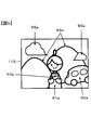
- FIG. 5 is a diagram schematically showing an image of a subject formed on the image sensor 32a of the camera 1.
- the camera 1 photoelectrically converts the subject image to obtain a live view image before an imaging instruction is given.
- the live view image refers to a monitor image that is repeatedly imaged at a predetermined frame rate (for example, 60 fps).
- the control unit 34 sets the same imaging condition over the entire area of the imaging chip 111 (that is, the entire imaging screen) before the setting unit 34b divides the area.
- the same imaging condition refers to setting a common imaging condition for the entire imaging screen. For example, even if there is a variation in apex value of less than about 0.3, it is regarded as the same.
- the imaging conditions set to be the same throughout the imaging chip 111 are determined based on the exposure conditions corresponding to the photometric value of the subject luminance or the exposure conditions manually set by the user.
- an image including a person 61a, an automobile 62a, a bag 63a, a mountain 64a, and clouds 65a and 66a is formed on the imaging surface of the imaging chip 111.
- the person 61a holds the bag 63a with both hands.
- the automobile 62a stops at the right rear of the person 61a.
- the control unit 34 divides the screen of the live view image into a plurality of regions as follows. First, a subject element is detected from the live view image by the object detection unit 34a. The subject element is detected using a known subject recognition technique. In the example of FIG. 5, the object detection unit 34a detects a person 61a, a car 62a, a bag 63a, a mountain 64a, a cloud 65a, and a cloud 66a as subject elements.
- the setting unit 34b divides the live view image screen into regions including the subject elements.
- the region including the person 61a is defined as the first region 61
- the region including the automobile 62a is defined as the second region 62
- the region including the bag 63a is defined as the third region 63
- the region including the mountain 64a is defined as the fourth region.
- the region 64, the fifth region including the cloud 65a will be referred to as a region 65
- the region including the cloud 66a will be described as a sixth region 66.
- the control unit 34 causes the display unit 35 to display a setting screen as illustrated in FIG. In FIG. 6, a live view image 60a is displayed, and an imaging condition setting screen 70 is displayed on the right side of the live view image 60a.
- the setting screen 70 lists frame rate, shutter speed (TV), and gain (ISO) in order from the top as an example of setting items for imaging conditions.
- the frame rate is the number of frames of a live view image acquired per second or a moving image recorded by the camera 1.
- Gain is ISO sensitivity.
- the setting items for the imaging conditions may be added as appropriate in addition to those illustrated in FIG. When all the setting items do not fit in the setting screen 70, other setting items may be displayed by scrolling the setting items up and down.
- the control unit 34 sets the region selected by the user among the regions divided by the setting unit 34b as a target for setting (changing) the imaging condition. For example, in the camera 1 capable of touch operation, the user taps the display position of the main subject for which the imaging condition is to be set (changed) on the display surface of the display unit 35 on which the live view image 60a is displayed. For example, when the display position of the person 61 a is tapped, the control unit 34 sets the area 61 including the person 61 a in the live view image 60 a as an imaging condition setting (change) target area and emphasizes the outline of the area 61. To display.
- an area 61 in which the outline is emphasized and displayed indicates an area for which the imaging condition is to be set (changed).
- a live view image 60a in which the outline of the region 61 is emphasized is displayed.
- the region 61 is a target for setting (changing) the imaging condition.
- the control unit 34 displays the current shutter speed for the highlighted area (area 61).
- the set value is displayed on the screen (reference numeral 68).
- the imaging condition may be set (changed) by operating a button or the like constituting the operation member 36.
- the setting unit 34b increases or decreases the shutter speed display 68 from the current setting value according to the tap operation.
- An instruction is sent to the imaging unit 32 (FIG. 1) so as to change the imaging condition of the unit area 131 (FIG. 3) of the imaging element 32a corresponding to the displayed area (area 61) in accordance with the tap operation.
- the decision icon 72 is an operation icon for confirming the set imaging condition.
- the setting unit 34b performs the setting (change) of the frame rate and gain (ISO) in the same manner as the setting (change) of the shutter speed (TV).
- the setting unit 34b may set the imaging condition based on the determination of the control unit 34 without being based on a user operation. For example, when the overexposure or underexposure occurs in the area including the subject element having the maximum luminance or the minimum luminance in the image, the setting unit 34b cancels the overexposure or underexposure based on the determination of the control unit 34.
- the imaging conditions may be set in. For the area that is not highlighted (the area other than the area 61), the set imaging conditions are maintained.
- the control unit 34 displays the entire target area brightly, increases the contrast of the entire target area, or displays the entire target area. May be displayed blinking.
- the target area may be surrounded by a frame.
- the display of the frame surrounding the target area may be a double frame or a single frame, and the display mode such as the line type, color, and brightness of the surrounding frame may be appropriately changed.
- the control unit 34 may display an indication of an area for which an imaging condition is set, such as an arrow, in the vicinity of the target area.
- the control unit 34 may darkly display a region other than the target region for which the imaging condition is set (changed), or may display a low contrast other than the target region.
- the control unit 34 is operated.
- imaging main imaging
- the divided areas are referred to as a first area 61 to a sixth area 66 (see FIG. 7A), and the first imaging condition to the sixth imaging 66 are included in the first area 61 to the sixth area 66, respectively.
- a condition shall be set.
- the image processing unit 33 performs image processing on the image data acquired by the imaging unit 32. This image data is image data recorded in the recording unit 37 and is hereinafter referred to as main image data.
- the image capturing unit 32 performs image processing on the main image data when acquiring the main image data, and image data used when performing various detection processes and setting processes for capturing the main image data. (Hereinafter referred to as processing image data) is acquired at a timing different from that of the main image data. Details of the image processing will be described later.
- the processing image data is an image of a target pixel included in a region (hereinafter referred to as a boundary portion) in the vicinity of a boundary that forms a boundary with another region in a certain region (for example, the first region 61). Used when processing. Further, the processing image data is used in focus detection processing, subject detection processing, and imaging condition setting processing.
- the setting unit 34b of the control unit 34 captures an area wider than the first area 61 for processing image data for the first area 61 (hereinafter referred to as first processing image data). Hereinafter, it is set in the image pickup device 32a as a processing image pickup region).
- the setting unit 34b sets, for example, the entire area of the imaging surface of the imaging element 32a as the processing imaging area. Further, the setting unit 34b sets a first imaging condition that is an imaging condition set in the first region 61 as the imaging condition of the first processing image data. Similarly, the setting unit 34b sets the processing imaging areas for the second to sixth processing image data to the entire area of the imaging surface of the imaging element 32a. The setting unit 34b sets the imaging conditions set in the second area 62 to the sixth area 66 as imaging conditions for the second to sixth processing image data, respectively. The timing for capturing the processing image data will be described later. In the following, the processing image data will be described separately for the case where it is used for image processing, the case where it is used for focus detection processing, the case where it is used for subject detection processing, and the case where it is used for exposure condition setting processing.
- the processing unit 33b of the image processing unit 33 when the image processing for the main image data acquired by applying different imaging conditions between the divided regions is predetermined image processing, the main image located at the boundary of the region Image processing is performed on the data using the processing image data.
- the predetermined image processing is processing for calculating data of a target position to be processed in an image with reference to data of a plurality of reference positions around the target position (hereinafter referred to as a target range). This includes defect correction processing, color interpolation processing, contour enhancement processing, noise reduction processing, and the like.
- the image processing is performed to alleviate the uncomfortable feeling that appears in the image after the image processing due to the difference in imaging conditions between the divided areas.
- data in which the same imaging condition as the target position data is applied to a plurality of reference positions in the target range, and different imaging conditions from the target position data May be mixed with data to which.
- the reference position data to which the same imaging condition is applied is referred to as reference position data to which the same imaging condition is applied, and the reference position data to which the same imaging condition is applied is referred to as it is.
- image processing is performed as follows.
- FIG. 7A is a diagram illustrating a predetermined range 80 including the first region 61 and the fourth region 64 that makes the boundary of the first region 61 in the live view image 60a.
- the first imaging condition is set in the first area 61 including at least a person
- the fourth imaging condition is set in the fourth area 64 including a mountain.
- FIG. 7B is an enlarged view of the predetermined range 80 in FIG.
- the image data from the pixels on the image sensor 32a corresponding to the first area 61 for which the first image capturing condition is set is shown in white, and the image data on the image sensor 32a corresponding to the fourth area 64 for which the fourth image capturing condition is set.
- the image data from the pixel is shaded.
- the image data from the target pixel P is located on the first region 61 and in the vicinity of the boundary 81 between the first region 61 and the fourth region 64, that is, the boundary portion.
- Pixels around the target pixel P (eight pixels in this example) included in the target range 90 (for example, 3 ⁇ 3 pixels) centered on the target pixel P are set as reference pixels Pr.
- FIG. 7C is an enlarged view of the target pixel P and the reference pixels Pr1 to Pr8.
- the position of the target pixel P is the target position, and the positions of the reference pixels Pr1 to Pr8 surrounding the target pixel P are reference positions.
- the reference symbol Pr is given to collectively refer to reference pixels.
- the processing unit 33b of the image processing unit 33 performs image processing using the image data of the reference pixel Pr as it is. That is, the processing unit 33b performs image processing such as interpolation using all data of all reference pixels Pr of the target pixel P. However, when the first imaging condition applied at the time of imaging in the target pixel P and the fourth imaging condition applied at the time of imaging in the reference pixels Pr around the target pixel P are different from each other, the processing unit 33b The image data of the fourth imaging condition on the data is not used. In FIG. 7C, the image data output from the target pixel P and the reference pixels Pr1 to Pr6 for which the first imaging condition is set is shown in white, and is output from the reference pixels Pr7 and Pr8 for which the fourth imaging condition is set.
- the image data to be processed is indicated by diagonal lines.
- the processing unit 33b does not use the image data of the fourth imaging condition, that is, the image data output from the reference pixels Pr7 and Pr8 indicated by diagonal lines in the image processing. Further, the processing unit 33b refers to the first processing image data generated by setting the first imaging condition instead of the image data of the reference pixels Pr7 and Pr8 of the main image data captured under the fourth imaging condition. Image data of the pixels Pr7 and Pr8 is used for image processing.
- FIG. 7D shows the pixels corresponding to the target pixel P and the reference pixel Pr of the main image data shown in FIG. 7C among the first processing image data, that is, the coordinates on the imaging surface of the imaging element 32a. Image data from pixels having the same value is shown. Since the first processing image data is captured under the first imaging condition, in FIG. 7D, pixel data output from the target pixel P and the reference pixel Pr is shown on a white background.
- the processing unit 33b selects the image data of the reference pixels Pr7 and Pr8 in the first processing image data instead of the image data of the reference pixels Pr7 and Pr8 in the main image data.
- the processing unit 33b refers to the image data of the reference pixels Pr1 to Pr6 in the main image data and the reference pixels Pr7 and Pr8 in the first processing image data, and determines the image data of the target pixel P of the main image data. calculate. That is, the processing unit 33b calculates the image data of the pixel of interest P using different image data captured with the same imaging condition set.
- the processing unit 33b of the image processing unit 33 includes the image data of the reference pixels Pr1 to Pr6 of the main image data acquired under the first imaging condition among the reference pixels Pr, and the first acquired with the ISO sensitivity of 100.
- Image processing is performed using the image data of the reference pixels Pr7 and Pr8 (FIG. 7D) of the processing image data.
- the processing unit 33b does not use the image data of the reference pixels Pr7 and Pr8 acquired under the fourth imaging condition (ISO sensitivity 800) among the reference pixels Pr acquired under the first imaging condition.
- Example 2 An example in which only the shutter speed is different between the first imaging condition and the fourth imaging condition, the shutter speed of the first imaging condition is 1/1000 second, and the shutter speed of the fourth imaging condition is 1/100 second.
- the target pixel P is acquired under the first imaging condition (shutter speed 1/1000 second).
- the processing unit 33b of the image processing unit 33 uses the image data of the reference pixels Pr1 to Pr6 of the main image data acquired at the shutter speed 1/1000 second out of the reference pixel Pr and the shutter speed at 1/1000 second. Image processing is performed using the image data of the reference pixels Pr7 and Pr8 of the acquired first processing image data.
- the processing unit 33b does not use the image data of the reference pixels Pr7 and Pr8 of the main image data acquired under the fourth imaging condition (shutter speed 1/100 seconds).
- Example 3 An example in which only the frame rate is different between the first imaging condition and the fourth imaging condition (the charge accumulation time is the same), the frame rate of the first imaging condition is 30 fps, and the frame rate of the fourth imaging condition is 60 fps.
- the target pixel P is acquired under the first imaging condition (30 fps).
- the processing unit 33b of the image processing unit 33 refers to the image data of the reference pixels Pr1 to Pr6 of the main image data acquired at 30 fps out of the reference pixels Pr and the first processing image data acquired at 30 fps. Image processing is performed using the image data of the pixels Pr7 and Pr8.
- the processing unit 33b does not use the image data of the reference pixels Pr7 and Pr8 of the main image data acquired under the fourth imaging condition (60 fps).
- the processing unit 33b of the image processing unit 33 when the first imaging condition applied at the time of imaging at the target pixel P and the imaging condition applied at all the reference pixels Pr around the target pixel P are the same. Uses data of the reference pixel Pr acquired under the first imaging condition for image processing. That is, the processing unit 33b uses the data of the reference pixel Pr as it is for image processing. As described above, even if there are some differences in the imaging conditions, the imaging conditions are regarded as the same.
- the processing unit 33b performs the image data of the reference pixel Pr acquired under the first imaging condition and the first data acquired under the first imaging condition on the image data of the target pixel P acquired under the first imaging condition.
- the present invention is not limited to performing image processing using the image data of the reference pixel Pr of one processing image data.
- the processing unit 33b does not use the image data of the reference pixels Pr1 to Pr8 of the main image data for the image data of the target pixel P acquired under the first imaging condition, but the reference pixels of the first processing image data.
- Image processing may be performed using image data of Pr1 to Pr8. That is, the processing unit 33b uses the image data of the reference pixel Pr imaged under the same imaging condition as the imaging condition set when the pixel of interest P is imaged, to the image data of the pixel of interest P. Image processing may be performed. *
- the imaging pixel defect correction process is one of image processes performed during imaging.
- the image sensor 100 which is a solid-state image sensor, may generate pixel defects during the manufacturing process or after manufacturing, and output abnormal level data. Therefore, the processing unit 33b of the image processing unit 33 performs image processing on the image data output from the imaging pixel in which the pixel defect has occurred, so that the image data at the position of the imaging pixel in which the pixel defect has occurred is inconspicuous. Like that.
- the processing unit 33b of the image processing unit 33 sets the pixel at the position of the pixel defect recorded in advance in a non-volatile memory (not shown) in the main image data as the target pixel P (processing target pixel), and the target pixel.
- a pixel (eight pixels in this example) around the target pixel P included in the target range 90 (for example, 3 ⁇ 3 pixels) centered on P is set as a reference pixel Pr.
- the processing unit 33b of the image processing unit 33 calculates the maximum value and the minimum value of the image data in the reference pixel Pr. When the image data output from the target pixel P exceeds these maximum value or minimum value, the processing unit 33b starts from the target pixel P. Max and Min filter processing is performed to replace the output image data with the maximum value or the minimum value. Such processing is performed on the image data from the imaging pixels in which all the pixel defects whose position information is recorded in the nonvolatile memory (not shown) are generated.
- the processing unit 33b of the image processing unit 33 refers to a pixel to which an imaging condition different from the imaging condition applied to the target pixel P at the time of imaging (the first imaging condition in the example of FIG. 7) is applied.
- the image data of the reference pixel Pr (Pr7, Pr8 in FIG. 7) of the first processing image data is selected.
- the generation unit 33c of the image processing unit 33 uses the Max and Min filters described above using the image data of the reference pixels Pr1 to Pr6 of the main image data and the image data of the reference pixels Pr7 and Pr8 of the first processing image data. Process.
- color interpolation processing is one of image processing performed at the time of imaging. As illustrated in FIG. 3, in the imaging chip 111 of the imaging element 32 a, green pixels Gb and Gr, a blue pixel B, and a red pixel R are arranged in a Bayer array.
- the processing unit 33b of the image processing unit 33 lacks image data of a color component different from the color component of the color filter F arranged at each pixel position, so that the insufficient color component with reference to the image data of the surrounding pixel positions
- the color interpolation processing for generating the image data is performed.
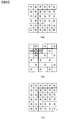
- FIG. 8A is a diagram illustrating the arrangement of image data output from the image sensor 32a. Corresponding to each pixel position, it has one of R, G, and B color components according to the rules of the Bayer array.
- the processing unit 33b of the image processing unit 33 that performs the G color interpolation refers to the image data of the four G color components at the reference positions around the target position, with the positions of the R color component and the B color component in turn as the target position.
- the G color component image data at the target position is generated. For example, when the G color component image data is generated at the target position indicated by the thick frame (second row, second column) in FIG.
- the image processing unit 33 sets, for example, (aG1 + bG2 + cG3 + dG4) / 4 as image data of the G color component at the target position.
- a to d are weighting coefficients provided according to the distance between the reference position and the target position and the image structure.
- the first imaging condition is applied to the left and upper regions with respect to the thick line
- the first imaging condition is applied to the right and lower regions with respect to the thick line.
- the processing unit 33b of the image processing unit 33 applies an imaging condition different from the first imaging condition applied to the target position to the reference position corresponding to the G color component image data G4 indicated by the oblique lines in FIG. Therefore, as the image data G4, the image data of the reference pixel Pr of the first processing image data is used.
- the processing unit 33b of the image processing unit 33 calculates the image data of the G color component at the target position using the image data of the reference pixels G1 to G4 to which the first imaging condition is applied.
- the processing unit 33b of the image processing unit 33 generates image data of the G color component at the position of the B color component and the position of the R color component in FIG.
- the image data of the G color component can be obtained at each pixel position.
- FIG. 9A is a diagram obtained by extracting R color component image data from FIG.
- the processing unit 33b of the image processing unit 33 uses the color difference component shown in FIG. 9B based on the G color component image data shown in FIG. 8C and the R color component image data shown in FIG. 9A. Cr image data is calculated.
- the processing unit 33b of the image processing unit 33 is located in the vicinity of the target position when generating image data of the color difference component Cr at the target position indicated by, for example, the thick frame (second row and second column) in FIG. 9B. Reference is made to the image data Cr1 to Cr4 of the four color difference components.
- the image processing unit 33 uses, for example, (eCr1 + fCr2 + gCr3 + hCr4) / 4 as image data of the color difference component Cr at the target position. Note that e to h are weighting coefficients provided according to the distance between the reference position and the target position and the image structure.
- the processing unit 33b of the image processing unit 33 generates image data of the color difference component Cr at the target position indicated by the thick frame (second row and third column) in FIG. 9C, for example, in the vicinity of the target position.
- the processing unit 33b of the image processing unit 33 uses, for example, (qCr2 + rCr4 + sCr5 + tCr6) / 4 as image data of the color difference component Cr at the target position.
- q to t are weighting coefficients provided according to the distance between the reference position and the target position and the image structure. In this way, image data of the color difference component Cr is generated for all pixels.
- the first imaging condition is applied to the left and upper regions with respect to the thick line, and the first imaging condition is applied to the right and lower regions with respect to the thick line.
- An imaging condition different from the first imaging condition applied to the target position (second row and second column) is applied to the reference position corresponding to the image data Cr2 of the color difference component Cr indicated by hatching in FIG. 9B. Yes.
- the image processing unit 33 (processing unit 33b) uses the image data of the reference pixel Pr of the first processing image data for the image data Cr2. Thereafter, the processing unit 33b of the image processing unit 33 calculates the image data of the color difference component Cr at the target position.
- the image processing unit 33 uses the image data of the reference pixel Pr of the processing image data for the image data Cr4 and Cr5. Thereafter, the processing unit 33b of the image processing unit 33 calculates the image data of the color difference component Cr at the target position.
- the processing unit 33b of the image processing unit 33 obtains the image data of the color difference component Cr at each pixel position, and then adds the image data of the G color component shown in FIG. 8C corresponding to each pixel position.
- the image data of the R color component can be obtained at each pixel position.
- FIG. 10A is a diagram in which image data of the B color component is extracted from FIG.
- the processing unit 33b of the image processing unit 33 uses the color difference component shown in FIG. 10B based on the image data of the G color component shown in FIG. 8C and the image data of the B color component shown in FIG. Cb image data is calculated.
- the processing unit 33b of the image processing unit 33 is located in the vicinity of the target position when generating image data of the color difference component Cb at the target position indicated by, for example, the thick frame (third row, third column) in FIG. Reference is made to the image data Cb1 to Cb4 of the four color difference components.
- the processing unit 33b of the image processing unit 33 uses, for example, (uCb1 + vCb2 + wCb3 + xCb4) / 4 as the image data of the color difference component Cb at the target position. Note that u to x are weighting coefficients provided according to the distance between the reference position and the target position and the image structure.
- the processing unit 33b of the image processing unit 33 generates the image data of the color difference component Cb at the target position indicated by the thick frame (third row and fourth column) in FIG. 10C, for example, in the vicinity of the target position.
- the processing unit 33b of the image processing unit 33 uses, for example, (yCb2 + zCb4 + ⁇ Cb5 + ⁇ Cb6) / 4 as image data of the color difference component Cb at the target position.
- y, z, ⁇ , and ⁇ are weighting coefficients provided in accordance with the distance between the reference position and the target position and the image structure. In this way, image data of the color difference component Cb is generated for all pixels.
- the first imaging condition is applied to the left and upper regions with respect to the thick line
- the first imaging condition is applied to the right and lower regions with respect to the thick line.
- the processing unit 33b of the image processing unit 33 is applied to the target position (third row, third column) at the reference position corresponding to the image data Cb1 and Cb3 of the color difference component Cb indicated by the oblique lines in FIG. Since the first imaging condition different from the imaging condition is applied, the image data of the reference pixel Pr of the processing image data is used for the data Cb1 and Cb3. Thereafter, the generation unit 33c of the image processing unit 33 calculates the image data of the color difference component Cb at the position of interest.
- the generation unit 33c of the image processing unit 33 calculates the image data of the color difference component Cb at the target position.
- the processing unit 33b of the image processing unit 33 obtains the image data of the color difference component Cb at each pixel position, and then adds the image data of the G color component shown in FIG. 8C corresponding to each pixel position.
- the image data of the B color component can be obtained at each pixel position.
- the processing unit 33b of the image processing unit 33 performs, for example, a known linear filter calculation using a kernel of a predetermined size centered on the target pixel P (processing target pixel) in one frame image.
- the kernel size of a sharpening filter that is an example of a linear filter is N ⁇ N pixels
- the position of the target pixel P is the target position
- the positions of (N 2 ⁇ 1) reference pixels surrounding the target pixel P are referred to.
- Position may be N ⁇ M pixels.
- the processing unit 33b of the image processing unit 33 performs a filter process for replacing the data in the target pixel P with the linear filter calculation result, for example, from the upper horizontal line to the lower horizontal line of the frame image, and the target pixel on each horizontal line. Shift from left to right.
- the processing unit 33b of the image processing unit 33 performs the first imaging when the reference pixel Pr includes a pixel to which an imaging condition different from the first imaging condition applied to the target pixel P is applied. For pixels to which imaging conditions different from the conditions are applied, the image data of the reference pixel Pr of the first processing image data is used. Thereafter, the generation unit 33c of the image processing unit 33 performs the linear filter processing described above.
- the processing unit 33b of the image processing unit 33 performs, for example, a known linear filter calculation using a kernel of a predetermined size centered on the target pixel P (processing target pixel) in one frame image.
- the kernel size of the smoothing filter which is an example of the linear filter is N ⁇ N pixels
- the position of the target pixel P is the target position
- the positions of the (N 2 ⁇ 1) reference pixels surrounding the target pixel P are referred to.
- Position may be N ⁇ M pixels.
- the processing unit 33b of the image processing unit 33 performs a filter process for replacing the data in the target pixel P with the linear filter calculation result, for example, from the upper horizontal line to the lower horizontal line of the frame image, and the target pixel on each horizontal line. Shift from left to right.
- the processing unit 33b of the image processing unit 33 performs processing when the reference pixel Pr includes a pixel to which an imaging condition different from the first imaging condition applied to the target pixel P during imaging is included. For pixels to which an imaging condition different from the one imaging condition is applied, the image data of the reference pixel Pr of the first processing image data is used. Thereafter, the processing unit 33b of the image processing unit 33 performs the linear filter processing described above.
- the setting unit 34b has been described as setting the entire area of the imaging surface of the imaging element 32a as a processing imaging area, but the present embodiment is not limited to this example.
- the setting unit 34b may set a partial area of the imaging surface of the imaging element 32a as a processing imaging area.
- the setting unit 34b sets an area corresponding to the first area 61 of the main image data as the processing imaging area, and applies the first imaging condition.
- the setting unit 34b sets, as the processing imaging region, the first region 61 and an outer region that is spread outward by, for example, a predetermined number of pixels from the outer periphery of the first region 61.
- the processing unit 33b divides the area on the imaging surface of the imaging element 32a in correspondence with each of the second area 62 to the sixth area 66 for areas other than the processing imaging area corresponding to the first area 61, and 2 imaging conditions to 6th imaging conditions are applied.
- the setting unit 34b applies the first imaging condition to the processing imaging area on the imaging surface including the area where the first imaging condition is set and the area where the other imaging conditions are set, and the imaging for processing is performed.
- An imaging condition different from the first imaging condition is applied to an area other than the area.
- the setting unit 34b similarly uses the processing imaging region set as an area wider than the second region 62 to the sixth region 66, and uses the processing unit 32b. Let's take an image.
- the setting unit 34b sets each region set in the main image data and the above-described outer region of each region from the image data captured by setting the entire region of the imaging surface of the image sensor 32a as the processing imaging region. It is also possible to extract the image data relating to the image data for processing. For example, the setting unit 34b sets the first imaging condition and sets the first area 61 of the main image data and the outside of the first area 61 from the image data captured using the entire area of the imaging surface of the imaging element 32a. Image data extracted from the region is generated as first processed image data. Also for the second processing image data to the sixth processing image data, the setting unit 34b applies the second imaging condition to the sixth imaging condition and applies each of the image data captured using the entire area of the imaging surface. The image data from the areas corresponding to the second area 62 to the sixth area 66 may be extracted as processing image data.
- the setting unit 34b is not limited to the one that sets the processing imaging area corresponding to each area set in the main image data.
- a processing imaging area may be set in advance in a partial area of the imaging surface of the imaging element 32a.
- the main subject is positioned when the person is imaged at the center of the screen as in portraits. It is possible to generate image data for processing in an area where there is a high possibility of this.
- the size of the imaging region for processing may be changeable based on a user operation, or may be fixed at a preset size.
- the setting unit 34b performs focus detection processing using processing image data that is captured with the same imaging condition set in the entire area of the imaging surface of the imaging element 32a. This is because when the focus point of the AF operation, that is, the focus detection area is divided into the first and second regions having different imaging conditions, the accuracy of the focus detection processing by the AF calculation unit 34d may be reduced.
- image data to which different imaging conditions are applied may be mixed in image data for focus detection that detects an image shift amount (phase difference) in an image.
- image data having no difference between image data due to differences in imaging conditions is used. Based on the idea that it is preferable to detect the amount of image shift (phase difference), focus detection processing using image data for processing is performed.
- the subject corresponding to the focus point selected by the user from a plurality of focus points on the imaging screen is focused.
- the AF calculation unit 34d of the control unit 34 detects the image shift amounts (phase differences) of the plurality of subject images due to the light beams that have passed through different pupil regions of the imaging optical system 31, thereby reducing the defocus amount of the imaging optical system 31. calculate.
- the AF calculation unit 34d of the control unit 34 moves the focus lens of the imaging optical system 31 to a position where the defocus amount is zero (allowable value or less), that is, a focus position.
- FIG. 11 is a diagram illustrating the position of the focus detection pixel on the imaging surface of the imaging device 32a.
- focus detection pixels are discretely arranged along the X-axis direction (horizontal direction) of the imaging chip 111.
- 15 focus detection pixel lines 160 are provided at a predetermined interval.
- the focus detection pixels constituting the focus detection pixel line 160 output a photoelectric conversion signal for focus detection.
- normal imaging pixels are provided at pixel positions other than the focus detection pixel line 160.
- the imaging pixel outputs a live view image or a photoelectric conversion signal for recording.
- FIG. 12 is an enlarged view of a part of the focus detection pixel line 160 corresponding to the focus point 80A shown in FIG.
- a red pixel R, a green pixel G (Gb, Gr), and a blue pixel B, a focus detection pixel S1, and a focus detection pixel S2 are illustrated.
- the red pixel R, the green pixel G (Gb, Gr), and the blue pixel B are arranged according to the rules of the Bayer arrangement described above.
- the square area illustrated for the red pixel R, the green pixel G (Gb, Gr), and the blue pixel B indicates a light receiving area of the imaging pixel.
- Each imaging pixel receives a light beam passing through the exit pupil of the imaging optical system 31 (FIG. 1). That is, the red pixel R, the green pixel G (Gb, Gr), and the blue pixel B each have a square-shaped mask opening, and light passing through these mask openings reaches the light-receiving portion of the imaging pixel. .
- the shapes of the light receiving regions (mask opening portions) of the red pixel R, the green pixel G (Gb, Gr), and the blue pixel B are not limited to a quadrangle, and may be, for example, a circle.
- the semicircular region exemplified for the focus detection pixel S1 and the focus detection pixel S2 indicates a light receiving region of the focus detection pixel. That is, the focus detection pixel S1 has a semicircular mask opening on the left side of the pixel position in FIG. 12, and the light passing through the mask opening reaches the light receiving portion of the focus detection pixel S1. On the other hand, the focus detection pixel S2 has a semicircular mask opening on the right side of the pixel position in FIG. 12, and the light passing through the mask opening reaches the light receiving portion of the focus detection pixel S2. As described above, the focus detection pixel S1 and the focus detection pixel S2 respectively receive a pair of light beams passing through different areas of the exit pupil of the imaging optical system 31 (FIG. 1).
- the position of the focus detection pixel line 160 in the imaging chip 111 is not limited to the position illustrated in FIG. Further, the number of focus detection pixel lines 160 is not limited to the example of FIG. Further, the shape of the mask opening in the focus detection pixel S1 and the focus detection pixel S2 is not limited to a semicircular shape. For example, a rectangular light receiving region (mask opening) in the imaging pixel R, the imaging pixel G, and the imaging pixel B is used. Part) may be a rectangular shape divided in the horizontal direction.
- the focus detection pixel line 160 in the imaging chip 111 may be a line in which focus detection pixels are arranged along the Y-axis direction (vertical direction) of the imaging chip 111.
- An imaging element in which imaging pixels and focus detection pixels are two-dimensionally arranged as shown in FIG. 12 is known, and detailed illustration and description of these pixels are omitted.
- the focus detection pixels S1 and S2 each receive one of the pair of focus detection light beams, the so-called 1PD structure.
- the focus detection pixels may be configured to receive both of a pair of light beams for focus detection, that is, a so-called 2PD structure.
- the photoelectric conversion signal obtained from the focus detection pixel can be used as a recording photoelectric conversion signal.
- the AF calculation unit 34d of the control unit 34 is a pair that passes through different regions of the imaging optical system 31 (FIG. 1) based on the focus detection photoelectric conversion signals output from the focus detection pixel S1 and the focus detection pixel S2. The amount of image misalignment (phase difference) between the pair of images due to the luminous flux is detected. Then, the defocus amount is calculated based on the image shift amount (phase difference). Such defocus amount calculation by the pupil division phase difference method is well known in the field of cameras, and thus detailed description thereof is omitted.
- the focus point 80A (FIG. 11) is selected by the user at a position corresponding to the predetermined range 80 in the first area 61 in the live view image 60a illustrated in FIG.
- FIG. 13 is an enlarged view of the focus point 80A.
- a white background pixel indicates that the first imaging condition is set, and a shaded pixel indicates that the fourth imaging condition is set.
- the position surrounded by the frame 170 corresponds to the focus detection pixel line 160 (FIG. 11).
- the AF calculation unit 34d of the control unit 34 normally performs focus detection processing using the image data of the focus detection pixels indicated by the frame 170 as they are. However, when image data to which the first imaging condition is applied and image data to which the fourth imaging condition is applied are mixed in the image data surrounded by the frame 170, the AF calculation unit 34d of the control unit 34 A focus detection process is performed using the first processing image data to which the imaging condition is applied. In this case, the AF calculation unit 34d of the control unit 34 uses image data corresponding to the range surrounded by the frame 170 in the first processing image data.
- Example 1 An example will be described in which only the ISO sensitivity differs between the first imaging condition and the fourth imaging condition, the ISO sensitivity of the first imaging condition is 100, and the ISO sensitivity of the fourth imaging condition is 800. Part of the image data surrounded by the frame 170 is acquired under the first imaging condition (ISO sensitivity 100), and the rest is acquired under the fourth imaging condition (ISO sensitivity 800). In this case, the AF calculation unit 34d of the control unit 34 performs focus detection processing using image data corresponding to a range surrounded by the frame 170 in the first processing image data to which the first imaging condition is applied. .
- Example 2 An example in which only the shutter speed is different between the first imaging condition and the fourth imaging condition, the shutter speed of the first imaging condition is 1/1000 second, and the shutter speed of the fourth imaging condition is 1/100 second.
- the AF calculation unit 34d of the control unit 34 corresponds to the image data corresponding to the range surrounded by the frame 170 in the first processing image data to which the first imaging condition (shutter speed 1/1000 second) is applied. Is used to perform focus detection processing.
- Example 3 An example in which only the frame rate is different between the first imaging condition and the fourth imaging condition (the charge accumulation time is the same), the frame rate of the first imaging condition is 30 fps, and the frame rate of the fourth imaging condition is 60 fps.
- the AF calculation unit 34d of the control unit 34 uses the image data corresponding to the range surrounded by the frame 170 in the first processing image data to which the first imaging condition (30 fps) is applied. Process.
- the AF calculation unit 34d of the control unit 34 may not use the processing image data when the imaging conditions applied in the image data surrounded by the frame 170 are the same. That is, the AF calculation unit 34d of the control unit 34 performs the focus detection process using the image data of the focus detection pixels indicated by the frame 170 as they are. As described above, even if there are some differences in the imaging conditions, the imaging conditions are regarded as the same.
- the focus detection process using the pupil division phase difference method is exemplified.
- the contrast detection method in which the focus lens of the imaging optical system 31 is moved to the in-focus position based on the contrast of the subject image. Can be done in the same way.
- the control unit 34 moves the focus lens of the imaging optical system 31 and outputs image data output from the imaging pixels of the imaging element 32a corresponding to the focus point at each position of the focus lens. Based on this, a known focus evaluation value calculation is performed. Then, the position of the focus lens that maximizes the focus evaluation value is obtained as the focus position.
- the control unit 34 normally performs a focus evaluation value calculation using the image data output from the imaging pixel corresponding to the focus point as it is. However, when the image data corresponding to the focus point includes image data to which the first imaging condition is applied and image data to which an imaging condition different from the first imaging condition is mixed, the control unit 34 A focus evaluation value calculation is performed using the first processing image data to which one imaging condition is applied.
- the setting unit 34b has been described as setting the entire area of the imaging surface of the imaging element 32a as a processing imaging area, but the present embodiment is not limited to this example.
- the setting unit 34b may set a partial area of the imaging surface of the imaging element 32a as a processing imaging area.
- the setting unit 34b sets a region including the frame 170, a region corresponding to the range including the focus point, and the vicinity of the center of the imaging surface of the imaging element 32a as the processing imaging region.
- the setting unit 34b sets an entire area on the imaging surface of the imaging element 32a as a processing imaging area, and an area corresponding to a range including the frame 170 or a range including the focus point from the captured image data. May be extracted as image data for processing.
- FIG. 14A is a diagram illustrating a template image representing an object to be detected
- FIG. 14B illustrates a live view image 60 (a) and a search range 190. It is a figure to do.
- the object detection unit 34a of the control unit 34 detects an object (for example, the bag 63a which is one of the subject elements in FIG. 5) from the live view image.
- the object detection unit 34a of the control unit 34 may set the range in which the object is detected as the entire range of the live view image 60a. However, in order to reduce the detection process, a part of the live view image 60a may be used as the search range 190. Good.
- the object detection unit 34a of the control unit 34 obtains processing image data that has been captured with the same imaging conditions set in all the regions of the imaging element 32a. And subject detection processing.
- image data to which different imaging conditions are applied may be mixed in the image data of the search range 190.
- image data having no difference between image data due to differences in imaging conditions is used in the search range 190. Based on the idea that it is preferable to detect the subject element, subject detection processing using the processing image data is performed.
- the object detection unit 34a of the control unit 34 sets the search range 190 in the vicinity of the region including the person 61a.
- the first area 61 including the person 61a may be set as the search range.
- the third imaging condition is set in the third region 63.
- the object detection unit 34a of the control unit 34 performs subject detection processing using the image data constituting the search range 190 as it is when the search range 190 is not divided by two regions having different imaging conditions. However, if the image data in the search range 190 includes image data to which the first imaging condition is applied and image data to which the third imaging condition is applied, the object detection unit 34a of the control unit 34 Processing image data is used. In this case, the subject detection unit 34a of the control unit 34 performs subject detection processing using the third processing image data imaged under the third imaging condition applied to the third region 63 corresponding to the bag 63a. Note that the set imaging conditions are the same as (Example 1) to (Example 3) described above for the case of performing focus detection processing.
- the control unit 34 searches for the search range in the processing image data. Tracking processing is performed using the image data.
- the control unit 34 detects the detection region used for detecting the motion vector in the processing image data.
- a motion vector is detected using the image data.
- the setting unit 34b has been described as setting the entire area of the imaging surface of the imaging element 32a as a processing imaging area, but the present embodiment is not limited to this example.
- the setting unit 34b may set a partial area of the imaging surface of the imaging element 32a as a processing imaging area.
- the setting unit 34b uses the range including the search range 190, the region corresponding to the range including the detection range used for detecting the motion vector, and the vicinity of the center of the imaging surface of the imaging element 32a as the processing imaging region.
- the setting unit 34b sets a range including the search range 190 and a detection range used for detecting a motion vector from image data captured by setting the entire area of the imaging surface of the imaging element 32a as a processing imaging area.
- the processing image data may be generated by extracting the included range.
- the exposure condition is determined by newly performing photometry, For image data located near the boundary of the region, processing image data is used. For example, when the photometric range set in the center of the imaging screen includes the boundary of the divided areas, image data to which different imaging conditions are applied may be mixed in the photometric range image data.
- the exposure calculation processing is performed using image data having no difference between the image data due to the difference in the imaging conditions, rather than performing the exposure calculation processing using the image data to which the different imaging conditions are applied as it is. Based on the idea that it is preferable, exposure calculation processing using processing image data is performed.
- the setting unit 34b of the control unit 34 performs the exposure calculation process using the image data constituting the photometric range as it is when the photometric range is not divided by a plurality of areas having different imaging conditions. However, if image data to which the first imaging condition is applied and image data to which the fourth imaging condition is applied are mixed in the image data in the photometric range (for example, an area including the boundary 80 in FIG. 7).
- the setting unit 34b of the control unit 34 uses processing image data. In this case, the setting unit 34 b of the control unit 34 performs the exposure calculation process using the first processing image data imaged under the first imaging condition applied to the first region 61.
- the set imaging conditions are the same as (Example 1) to (Example 3) described above for the case of performing focus detection processing.
- the photometric range when performing the exposure calculation process described above but also the photometric (colorimetric) range used when determining the white balance adjustment value and the necessity of emission of the auxiliary photographing light by the light source that emits the auxiliary photographing light are determined. The same applies to the photometric range performed at the time, and further to the photometric range performed at the time of determining the light emission amount of the photographing auxiliary light by the light source.
- the area used for the determination of the imaging scene performed when determining the readout resolution for each area can be similarly handled. .
- the setting unit 34b has been described as setting the entire area of the imaging surface of the imaging element 32a as a processing imaging area, but the present embodiment is not limited to this example.
- the setting unit 34b may set a partial area of the imaging surface of the imaging element 32a as a processing imaging area.
- the setting unit 34b sets a region corresponding to a range including the photometric range or a vicinity of the center of the imaging surface of the imaging element 32a as the processing imaging region.
- the setting unit 34b sets the entire area of the imaging surface of the image sensor 32a as a processing imaging area and extracts a range that includes a photometric range from the captured image data to obtain each processing image data. It may be generated.
- timing for generating the processing image data used in the various processes described above will be described.
- the timing for generating processing image data used for image processing and the timing for generating processing image data used for focus detection processing, subject detection processing, and exposure condition setting processing (hereinafter referred to as detection / setting processing). Separately, it explains.
- the imaging control unit 34c causes the processing image data to be captured at a timing different from the timing at which the imaging unit 32 captures the main image data.
- the imaging control unit 34c causes the imaging unit 32 to capture the processing image data when the live view image is displayed or when the operation member 36 is operated. Further, the imaging control unit 34c outputs information on the imaging conditions set in the processing image data by the setting unit 34b when instructing imaging of the processing image data.
- description will be made separately on imaging of processing image data when displaying a live view image and imaging of processing image data when operating the operation member 36.
- the imaging control unit 34c causes the imaging unit 32 to capture image data for processing after an operation for instructing the display start of the live view image is performed by the user.
- the imaging control unit 34c causes the imaging unit 32 to capture the processing image data for each predetermined period while the live view image is displayed. For example, in the frame rate of the live view image, the imaging control unit 34c, for example, at the timing of capturing an even frame or the next timing of capturing a 10 frame live view image, instead of an instruction to capture the live view image.
- a signal instructing imaging of the processing image data is output to the imaging unit 32.
- the imaging control unit 34c causes the imaging unit 32 to capture the processing image data under the imaging conditions set by the setting unit 34b.
- FIG. 15 is used to illustrate the relationship between the timing of capturing image data for a live view image and the timing of capturing image data for processing.
- FIG. 15A shows a case where imaging of a live view image and imaging of processing image data are alternately performed every other frame. It is assumed that the first imaging condition to the third imaging condition are set for the first area 61 to the third area 63 (FIG. 7A) by the user's operation. At this time, the first processing image data D1 in which the first imaging condition is set and the second imaging condition in which the second imaging condition is set are used for processing each of the first area 61 to the third area 63 of the main image data. The second processing image data D2 and the third processing image data D3 for which the third imaging condition is set are captured.
- the imaging control unit 34c instructs the imaging unit 32 to capture the live view image LV1 of the Nth frame, and the control unit 34 causes the display unit 35 to display the live view image LV1 obtained by the imaging.
- the imaging control unit 34c instructs the imaging unit 32 to image the first processing image data D1 to which the first imaging condition is applied.
- the imaging control unit 34c records the captured first processing image data D1 on a predetermined recording medium (not shown).
- the control unit 34 causes the display unit 35 to display the live view image LV1 captured at the imaging timing of the Nth frame as the live view image of the (N + 1) th frame. That is, the display of the live view image LV1 of the previous frame is continued.
- the imaging control unit 34c instructs the imaging unit 32 to image the live view image LV2 of the (N + 2) th frame.
- the control unit 34 switches from displaying the live view image LV1 on the display unit 35 to displaying the live view image LV2 obtained by imaging the (N + 2) th frame.
- the imaging control unit 34c causes the imaging unit 32 to image the second processing image data D2 to which the second imaging condition is applied, and records the captured second processing image data D2. To do. Also in this case, the control unit 34 continues to display the live view image LV ⁇ b> 2 captured at the imaging timing of the (N + 2) th frame as the live view image of the (N + 3) th frame on the display unit 35.
- the imaging control unit 34c causes the imaging unit 32 to capture the live view image LV3, and the control unit 34 displays the captured live view image LV3 on the display unit. 35.
- the imaging control unit 34c causes the imaging unit 32 to capture the third processing image data D3 to which the third imaging condition is applied.
- the control unit 34 continues to display the live view image LV3 in the (N + 4) th frame on the display unit 35.
- the control unit 34 repeatedly performs the processes in the Nth to N + 5th frames.
- the imaging control unit 34c captures image data for processing (see FIG.
- the imaging unit 32 may perform imaging by applying imaging conditions newly set in the 15th (a) (N + 1, N + 3, N + 5 frames).
- the imaging control unit 34c may cause the imaging unit 32 to capture the processing image data before starting to display the live view image. For example, when the user turns on the power of the camera 1 or when an operation for instructing to start displaying the live view image is performed, a signal instructing the imaging unit 32 to image the processing image data is output. The imaging control unit 34c instructs the imaging unit 32 to capture the live view image when imaging of the first to third processing image data is completed.
- the imaging control unit 34c captures the first processing image data D1 under the first imaging condition and the second imaging condition under the timing at which the first to third frames are imaged.
- the second processing image data D2 and the third processing image data D3 under the third imaging condition are respectively captured.
- the imaging control unit 34c causes the live view images LV1, LV2, LV3,... To be captured, and the control unit 34 causes the display unit 35 to sequentially display the live view images LV1, LV2, LV3,.
- the imaging control unit 34c may cause the imaging unit 32 to capture the processing image data at the timing when the user performs an operation to end the display of the live view image while the live view image is displayed. That is, when an operation signal corresponding to an operation for instructing the end of the display of the live view image is input from the operation member 36, the imaging control unit 34c outputs a signal for instructing the imaging unit 32 to end the imaging of the live view image. When the imaging unit 32 finishes capturing the live view image, the imaging control unit 32c outputs a signal instructing imaging of the processing image data to the imaging unit 32.
- the imaging control unit 34c sets the first imaging condition in the (N + 1) th to (N + 3) th frames.
- the first processing image data D1, the second processing image data D2 under the second imaging condition, and the third processing image data D3 under the third imaging condition are each captured.
- the control unit 34 may display the live view image LV1 captured in the Nth frame on the display unit 35 during the period of the (N + 1) th to (N + 3) th frames, or may not display the live view image. Also good.
- the imaging control unit 34c may capture the processing image data.
- the setting unit 34b sets different imaging conditions for each frame in the entire area of the imaging surface of the imaging element 32a.
- the control unit 34 displays the generated processing image data on the display unit 35 as a live view image.
- the imaging control unit 34c may capture the processing image data. For example, imaging is performed when the position of the subject element detected by the control unit 34 (setting unit 34b) based on the live view image is shifted by a predetermined distance or more compared to the position of the subject element detected in the previous frame.
- the control unit 34c may instruct to capture the processing image data.
- the operation of the operation member 36 for imaging the processing image data includes half-pressing of the release button by the user, that is, an operation for instructing preparation for imaging, a full-pressing operation of the release button, That is, an operation for instructing the main imaging can be given.
- the imaging control unit 34c may cause the imaging unit 32 to capture the processing image data at a timing when the operation of the release button by the user ends, for example, by shifting from a half-press operation to a full-press operation. That is, the imaging control unit 36c may output a signal for instructing imaging to the imaging unit 32 at a timing when an operation signal corresponding to an operation for instructing preparation for imaging is not input from the operation member 36.
- the imaging control unit 34c may cause the imaging unit 32 to capture the processing image data while the release button is pressed halfway by the user. In this case, the imaging control unit 34c can output a signal instructing imaging to the imaging unit 32 at every predetermined period. Thus, the processing image data can be captured while the release button is half-pressed by the user. Alternatively, the imaging control unit 34c may output a signal for instructing imaging to the imaging unit 32 in accordance with the timing at which the live view image is captured. In this case, the imaging control unit 34c instructs the imaging of the processing image data at the timing of capturing an even frame, for example, at the next timing after capturing the live view image of 10 frames, of the frame rate of the live view image. May be output to the imaging unit 32. Further, when the processing image data is captured while the live view image is displayed, the processing image data may not be captured based on the half-press operation of the release button.
- (2-2) Release button full-press operation When the user performs a full-press operation of the release button, that is, an operation for instructing main imaging, an operation signal is output from the operation member 36.
- the imaging control unit 34c of the control unit 34 When an operation signal corresponding to an operation for instructing main imaging is input from the operation member 36, the imaging control unit 34c of the control unit 34 outputs a signal for instructing main imaging to the imaging unit 32. After the main image data is picked up by the main image pickup, the image pickup control unit 34c outputs a signal instructing to pick up the processing image data. That is, after an operation for instructing imaging is performed by the user, the imaging unit 32 captures the main image data by the main imaging and then captures the processing image data.
- the imaging control unit 34c may cause the imaging unit 32 to capture the processing image data before capturing the main image data. Further, when the processing image data is captured while the live view image is displayed, the processing image data may not be captured based on the half-press operation of the release button.
- the operation of the operation member 36 for capturing the processing image data is not limited to a half-press operation or a full-press operation of the release button.
- the imaging control unit 34c may instruct imaging of the processing image data.
- operations related to imaging there are, for example, an operation for changing an imaging magnification, an operation for changing an aperture, an operation related to focus adjustment (for example, selection of a focus point), and the like.
- the imaging control unit 34c causes the imaging unit 32 to capture the processing image data.
- main imaging is performed under new settings, it is possible to generate processing image data imaged under the same conditions as the main imaging.
- the imaging control unit 34c may capture the processing image data. This is because, when an operation related to imaging is performed from the menu screen, there is a high possibility that new settings will be made for the actual imaging. In this case, the imaging unit 32 captures the processing image data while the menu screen is open.
- the processing image data may be captured at predetermined intervals, or may be captured at a frame rate when capturing a live view image.
- the imaging control unit 34c When an operation not related to imaging, for example, an operation for reproducing and displaying an image, an operation during reproduction display, or an operation for clock adjustment is performed, the imaging control unit 34c captures image data for processing. Does not output the instruction signal. That is, the imaging control unit 34c does not cause the imaging unit 32 to capture the processing image data. Thereby, it is possible to prevent the image data for processing from being imaged when the possibility that a new setting for the main imaging is performed is low or the possibility that the main imaging is performed is low.
- the imaging control unit 34c causes the imaging unit 32 to capture the processing image data when the dedicated button is operated by the user. Instruct.
- the imaging control unit 34c performs the predetermined period during the period when the dedicated button is operated.
- the image data for processing may be imaged by the imaging unit 32, or the image data for processing may be imaged when the operation of the dedicated button is completed. As a result, the processing image data can be captured at a timing desired by the user. Further, when the power of the camera 1 is turned on, the imaging control unit 34c may instruct the imaging unit 32 to capture the processing image data.
- all of the exemplified methods may be applied to capture the processing image data, or at least one method may be performed, and the user selects from each method.
- a method may be performed. Selection by the user can be performed from a menu screen displayed on the display unit 35, for example.
- the imaging control unit 34c images the processing image data used for the detection / setting process at various timings similar to the timing for generating the processing image data used for the image processing described above. That is, the same image data can be used as processing image data used for detection / setting processing or processing image data used for image processing.
- the processing image data used for the detection / setting process is generated at a timing different from the timing of generating the processing image data used for the image processing will be described.
- the imaging control unit 34c causes the imaging unit 32 to capture the processing image data before imaging the main image data. In this case, a result detected using the latest processing image data imaged immediately before the main imaging or a set result can be reflected in the main imaging.
- the imaging control unit 34c captures image data for processing.
- the imaging control unit 34c may generate one frame of processing image data, or may generate a plurality of frames of processing image data.
- the processing image data is used for the image processing, the focus detection processing, the subject detection processing, and the exposure setting processing is described as an example.
- the processing image data is limited to the processing image data used for all processing. What is used for at least one of the above processes is included in the present embodiment. Which process the image data for processing is used for may be configured so that the user can select and determine from the menu screen displayed on the display unit 35.
- FIG. 16 is a flowchart for explaining the flow of processing for setting an imaging condition for each area and imaging.
- the control unit 34 activates a program that executes the process shown in FIG.
- step S10 the control unit 34 causes the display unit 35 to start live view display, and proceeds to step S20.
- the control unit 34 instructs the imaging unit 32 to start acquiring a live view image, and causes the display unit 35 to sequentially display the acquired live view image.
- the same imaging condition is set for the entire imaging chip 111, that is, the entire screen.
- the AF calculation unit 34d of the control unit 34 performs focus detection processing to focus on the subject element corresponding to a predetermined focus point. Control the behavior. If the setting for performing the AF operation is not performed during live view display, the AF calculation unit 34d of the control unit 34 performs the AF operation when the AF operation is instructed later.
- step S20 the object detection unit 34a of the control unit 34 detects the subject element from the live view image and proceeds to step S30.
- step S30 the setting unit 34b of the control unit 34 divides the screen of the live view image into regions including subject elements, and proceeds to step S40.
- step S ⁇ b> 40 the control unit 34 displays an area on the display unit 35. As illustrated in FIG. 6, the control unit 34 highlights an area that is a target for setting (changing) the imaging condition among the divided areas. In addition, the control unit 34 displays the imaging condition setting screen 70 on the display unit 35 and proceeds to step S50. Note that, when the display position of another main subject on the display screen is tapped with the user's finger, the control unit 34 sets the region including the main subject as a region for setting (changing) the imaging condition. Change and highlight.
- step S50 the control unit 34 determines whether an AF operation is necessary.
- the control unit 34 for example, when the focus adjustment state changes due to the movement of the subject, when the position of the focus point is changed by a user operation, or when execution of an AF operation is instructed by a user operation, An affirmative decision is made in step S50 and the process proceeds to step S70. If the focus adjustment state does not change, the position of the focus point is not changed by the user operation, and the execution of the AF operation is not instructed by the user operation, the control unit 34 makes a negative determination in step S50 and proceeds to step 60. .
- step S70 the control unit 34 performs the AF operation and returns to step S40.
- the control unit 34 that has returned to step S40 repeats the same processing as described above based on the live view image acquired after the AF operation.
- step S60 the setting unit 34b of the control unit 34 sets an imaging condition for the highlighted area in accordance with a user operation, and proceeds to step S80. That is, imaging conditions are set for each of a plurality of areas. Note that the display transition of the display unit 35 and the setting of the imaging conditions according to the user operation in step S60 are as described above.
- step S80 the control unit 34 determines whether to capture the processing image data while the live view image is displayed. If it is set to capture the processing image data while the live view image is being displayed, an affirmative determination is made in step S80 and the process proceeds to step S90. If the setting for capturing the processing image data is not made during the display of the live view image, a negative determination is made in step S80, and the process proceeds to step S100 described later.
- step S90 the imaging control unit 34c of the control unit 34 instructs the imaging unit 32 to perform imaging of the processing image data for each set imaging condition at a predetermined period during imaging of the live view image. Then, the process proceeds to step S100.
- the control unit 34 determines the presence / absence of an imaging instruction. When the release button constituting the operation member 36 or the display icon for instructing imaging is operated, the control unit 34 makes a positive determination in step S100 and proceeds to step S110. When the imaging instruction is not performed, the control unit 34 makes a negative determination in step S100 and returns to step S60.
- step S110 the control unit 34 performs imaging processing of the processing image data and the main image data. That is, the imaging control unit 34c captures the processing image data for each of the different imaging conditions set in step S60, and performs the actual imaging with the imaging conditions set for each of the areas in step S60. To obtain the main image data and proceed to step S120. Note that, when processing image data used for detection / setting processing is captured, the processing image data is captured before capturing the main image data. If the processing image data is captured in step S90, the processing image data may not be captured in step S110.
- step S120 the imaging control unit 34c of the control unit 34 sends an instruction to the image processing unit 33, and predetermined processing is performed using the processing image data obtained in step S90 or step S110 on the main image data obtained by the imaging.
- the image processing is performed, and the process proceeds to step S130.
- Image processing includes the pixel defect correction processing, color interpolation processing, contour enhancement processing, and noise reduction processing.
- step S130 the control unit 34 sends an instruction to the recording unit 37, records the image data after the image processing on a recording medium (not shown), and proceeds to step S140.
- step S140 the control unit 34 determines whether an end operation has been performed. When the end operation is performed, the control unit 34 makes a positive determination in step S140 and ends the process illustrated in FIG. If the end operation is not performed, the control unit 34 makes a negative determination in step S140 and returns to step S20. When returning to step S20, the control unit 34 repeats the above-described processing.
- the main imaging is performed under the imaging conditions set in step S60, and the processing is performed on the main image data using the processing image data obtained in step S90 or S110.
- the focus detection process, the subject detection process, and the imaging condition setting process are obtained while the live view image is displayed in step S90. This is performed based on the processed image data.
- the multilayer image sensor 100 is illustrated as the image sensor 32a.
- the imaging condition can be set for each of a plurality of blocks in the image sensor (imaging chip 111)
- the image sensor 32a is not necessarily configured as a multilayer image sensor. do not have to.
- the camera 1 includes an input unit 33a and a processing unit 33b.
- the input unit 33a captures an image by setting a first imaging condition in the first region of the imaging surface of the imaging unit 32 and setting a second imaging condition different from the first imaging condition in the second region of the imaging surface.
- the main image data and the processing image data imaged by setting the third imaging condition in the first area and the second area are input.
- the processing unit 33b performs image processing on the first partial image data corresponding to the first region in the main image data using the processing image data.
- the camera 1 can generate
- the processing unit 33b performs image processing on the boundary portion data corresponding to the first region, the second region, and the boundary portion 80 of the first partial image data using the processing image data.
- the camera 1 can appropriately perform image processing using the image data generated in the regions having different imaging conditions. For example, discontinuity and discomfort appearing in the main image data after image processing can be suppressed due to differences in imaging conditions at the boundaries of the regions.
- the processing unit 33b performs image processing on the boundary data of the main image data by using image data corresponding to at least the second region of the processing image data.
- the camera 1 can appropriately perform image processing using the image data generated in the regions having different imaging conditions. For example, discontinuity and discomfort appearing in the main image data after image processing can be suppressed due to differences in imaging conditions at the boundaries of the regions.
- the processing unit 33b determines the reference pixels Pr around the target pixel P and corresponding to the first region and the second region with respect to the target pixel P of the data in the boundary 80 of the main image data.
- the processing image data at the position corresponding to the position of the reference pixel Pr in the main image data is used for the image processing.
- the camera 1 can appropriately perform image processing using the image data generated in the regions having different imaging conditions. For example, discontinuity and discomfort appearing in the main image data after image processing can be suppressed due to differences in imaging conditions at the boundaries of the regions.
- the processing unit 33b further uses the main image data at the position of the reference pixel Pr for image processing.
- the camera 1 can appropriately perform image processing using the image data generated in the regions having different imaging conditions.
- the processing unit 33b further uses processing image data at a position corresponding to the position of the reference pixel Pr in the main image data for image processing.
- the camera 1 can appropriately perform image processing using the image data generated in the regions having different imaging conditions. For example, discontinuity and discomfort appearing in an image after image processing can be suppressed due to a difference in imaging conditions at the boundary between regions.
- the imaging control unit 34c controls the timing of performing the main imaging by the imaging unit 32 and the timing of imaging the processing image data. Thereby, it is possible to acquire processing image data used for image processing of the main image data.
- the imaging control unit 34c causes the imaging unit 32 to capture the processing image data between the frames of the live view image, and causes at least one frame of the processing image data to be captured. By capturing the processing image data while capturing the live view image, it is possible to perform appropriate image processing using the processing image data when capturing the main image data.
- the imaging control unit 34c captures the live view image before the imaging unit 32 starts imaging the live view image in the imaging preparation state or after the imaging unit 32 starts imaging the live view image. Every time the predetermined number of frames are performed, the processing image data is captured to capture at least one frame of processing image data. By capturing the processing image data while capturing the live view image, it is possible to perform appropriate image processing using the processing image data when capturing the main image data.
- the imaging control unit 34c receives at least one frame of processing image data before the imaging unit 32 performs main imaging or after performing main imaging. Let's take an image. Image data for processing is captured at the stage of transition from live view image capturing to main image capturing, and appropriate image processing using the processing image data can be performed when the main image data is captured. When processing image data is captured after the main imaging, the main imaging can be performed without missing a photo opportunity.
- the imaging control unit 34c causes the imaging unit 32 to capture at least one frame of processing image data before the display unit 35 displays the live view image again after the main imaging by the imaging unit 32 is completed. Thereby, the processing image data can be prepared in preparation for a new main imaging.
- the imaging control unit 34c causes the imaging unit 32 to capture image data for processing when an instruction related to imaging including an instruction for preparation for actual imaging and an instruction for actual imaging is performed.
- an instruction related to imaging including an instruction for preparation for actual imaging and an instruction for actual imaging is performed.
- the imaging control unit 34c causes the imaging unit 32 to capture at least one frame of processing image data while an operation for instructing preparation for main imaging is being performed. As a result, it is possible to capture the processing image data before the main imaging and perform appropriate image processing using the processing image data when the main image data is captured.
- the imaging control unit 34c images at least one frame of processing image data to the imaging unit 32 before the imaging unit 32 performs the main imaging or after the main imaging when an operation for instructing the main imaging is performed. Let As a result, it is possible to capture the processing image data before the main imaging and perform appropriate image processing using the processing image data when the main image data is captured. When processing image data is captured after the main imaging, the main imaging can be performed without missing a photo opportunity.
- the imaging control unit 34c causes the imaging unit 32 to capture at least one frame of processing image data.
- the user can operate the dedicated button at the timing desired by the user, such as when the user determines that the imaging conditions are likely to change. Image data can be captured.
- the imaging unit 32 captures the processing image data in a partial region of the imaging surface. As a result, the processing image data can be acquired for an area of the main image data that requires image processing.
- the imaging unit 32 captures the processing image data at the center of the imaging surface or the area at the designated position. As a result, the processing image data can be acquired for an area of the main image data that requires image processing.
- the imaging unit 32 makes the imaging conditions common or different in the plurality of frames when imaging the processing image data in a plurality of frames. As a result, even when the imaging conditions are different among the plurality of divided areas, the processing image data used for each area can be captured.
- the setting unit 34b determines the imaging condition of the next frame based on the processing image data acquired in the previous frame of the plurality of frames when the imaging conditions are different in the plurality of frames of the processing image data. Therefore, even when the imaging condition changes during the display of the live view image, it is possible to capture the processing image data suitable for the image processing.
- the setting unit 34b sets the designated imaging condition and performs imaging of the processing image data. Thereby, it is possible to capture processing image data suitable for image processing on the main image data to which the imaging condition desired by the user is applied.
- FIGS. 17A to 17C are diagrams illustrating the arrangement of the first region and the second region on the imaging surface of the imaging device 32a.
- the first region is configured by even columns
- the second region is configured by odd columns. That is, the imaging surface is divided into even columns and odd columns.
- the first region is configured by odd rows
- the second region is configured by even rows. That is, the imaging surface is divided into odd rows and even rows.
- the first region is configured by blocks of even rows in odd columns and blocks of odd rows in even columns.
- the second region is configured by even-numbered blocks in even columns and odd-numbered blocks in odd columns. That is, the imaging surface is divided into a checkered pattern.
- a first imaging condition is set in the first area
- a second imaging condition different from the first imaging condition is set in the second area.
- the first image based on the photoelectric conversion signal read from the first region and the photoelectric conversion signal read from the image pickup element 32a that has picked up an image of one frame, and Second images based on the photoelectric conversion signals read from the second region are respectively generated.
- the first image and the second image are captured at the same angle of view and include a common subject image.
- the control unit 34 uses the first image for display and the second image as processing image data. Specifically, the control unit 34 causes the display unit 35 to display the first image as a live view image.
- the control unit 34 uses the second image as processing image data. That is, the processing unit 33b performs image processing using the second image, the object detection unit 34a performs subject detection processing using the second image, and the AF calculation unit 34d performs focus detection processing using the second image. And the exposure calculation process is performed by the setting unit 34b using the second image.
- the first image from the first region is captured as a live view image
- the second image from the second region is captured as processing image data
- the first image is processed as processing image data.
- the second image may be captured as a live view image, and this operation may be repeated in subsequent frames.
- the control unit 34 captures a live view image under the first imaging condition, and sets the first imaging condition to a condition suitable for display by the display unit 35.
- the first imaging condition is the same for the entire imaging screen.
- the control unit 34 captures the processing image data under the second imaging condition, and sets the second imaging condition to a condition suitable for the focus detection process, the subject detection process, and the exposure calculation process.
- the second imaging condition is also made the same for the entire imaging screen.
- the control unit 34 may change the second imaging condition set in the second area for each frame.
- the second imaging condition of the first frame is a condition suitable for the focus detection process
- the second imaging condition of the second frame is a condition suitable for the subject detection process
- the second imaging condition of the third frame is the exposure calculation process.
- Conditions suitable for In these cases, the second imaging condition in each frame is the same for the entire imaging screen.
- control unit 34 may change the first imaging condition on the imaging screen.
- the setting unit 34b of the control unit 34 sets different first imaging conditions for each region including the subject element divided by the setting unit 34b.
- the control unit 34 makes the second imaging condition the same for the entire imaging screen.
- the control unit 34 sets the second imaging condition to a condition suitable for the focus detection process, the subject detection process, and the exposure calculation process. However, the conditions suitable for the focus detection process, the subject detection process, and the exposure calculation process are set. If they are different, the imaging conditions set in the second area may be different for each frame.
- control unit 34 may change the second imaging condition on the imaging screen while making the first imaging condition the same on the entire imaging screen. For example, a different second imaging condition is set for each region including the subject element divided by the setting unit 34b. Even in this case, if the conditions suitable for the focus detection process, the subject detection process, and the exposure calculation process are different, the imaging conditions set in the second region may be different for each frame.
- control unit 34 makes the first imaging condition different on the imaging screen and makes the second imaging condition different on the imaging screen.
- the setting unit 34b sets different first imaging conditions for each region including the subject element divided, and the setting unit 34b sets different second imaging conditions for each region including the subject element divided.
- the area ratio between the first region and the second region may be different.
- the control unit 34 sets the ratio of the first region to be higher than that of the second region based on the operation by the user or the determination of the control unit 34, or sets the ratio of the first region to the second region as shown in FIG. As shown in FIG. 17C, the setting is made equal, or the ratio of the first area is set lower than that of the second area.
- the first image is made higher in definition than the second image by averaging the image signals from the blocks in the second region.
- Modification 2 In the above-described embodiment, the example in which the setting unit 34b of the control unit 34 detects the subject element based on the live view image and divides the screen of the live view image into regions including the subject element has been described.
- the control unit 34 may divide the region based on the output signal from the photometric sensor when the photometric sensor is provided separately from the image sensor 32a.
- FIG. 18 is a block diagram showing a main configuration of the second modification.
- the camera 1 includes a photometric sensor 38 in addition to the configuration in the embodiment shown in FIG.
- the control unit 34 divides the foreground and the background based on the output signal from the photometric sensor 38. Specifically, the live view image acquired by the image sensor 32 b is determined to be the foreground area corresponding to the area determined to be the foreground from the output signal from the photometry sensor 38 and the background from the output signal from the photometry sensor 38. Is divided into a background area corresponding to the selected area.
- control unit 34 arranges the first area and the second area on the imaging surface of the imaging element 32a as illustrated in FIGS. 17A to 17C with respect to the foreground area. On the other hand, the control unit 34 arranges only the first area on the imaging surface of the imaging element 32a with respect to the background area. The control unit 34 uses the first image for display and the second image for detection.
- the second modification by using the output signal from the photometric sensor 38, it is possible to divide the live view image acquired by the image sensor 32b.
- a first image for display and a second image for detection can be obtained for the foreground area, and only a first image for display can be obtained for the background area.
- the foreground area and the background area can be newly set by performing area division using the output from the photometric sensor 38. it can.
- the present invention is not limited to the example in which the photometric sensor 38 detects the imaging environment of the subject. For example, based on the output of an acceleration sensor or the like that detects the acceleration applied to the camera 1, the region is divided according to the imaging environment of the subject Also good.
- the image processing unit 33 does not impair the outline of the subject element in the above-described image processing (for example, noise reduction processing).
- image processing for example, noise reduction processing
- smoothing filter processing is employed when noise reduction is performed.
- the boundary of the subject element may be blurred while the noise reduction effect.
- the processing unit 33b of the image processing unit 33 compensates for the blur of the subject element boundary by performing contrast adjustment processing in addition to or together with noise reduction processing, for example.
- the processing unit 33b of the image processing unit 33 sets a curve that draws an S shape as a density conversion (gradation conversion) curve (so-called S-shaped conversion).
- the processing unit 33b of the image processing unit 33 increases the number of gradations of bright data (and dark data) by extending the gradation portions of bright data and dark data by performing contrast adjustment using S-shaped conversion.
- the number of gradations is reduced by compressing the intermediate gradation image data.
- the number of image data having a medium brightness is reduced, and data classified as either bright / dark is increased.
- blurring of the boundary of the subject element can be compensated.
- blurring of the boundary of the subject element can be compensated by clearing the contrast of the image.
- a plurality of image processing units 33 may be provided, and image processing may be performed in parallel. For example, image processing is performed on the image data captured in the region B of the imaging unit 32 while performing image processing on the image data captured in the region A of the imaging unit 32.
- the plurality of image processing units 33 may perform the same image processing or different image processing. That is, the same parameters are applied to the image data of the region A and the region B, and the same image processing is performed, or the different parameters are applied to the image data of the region A and the region B to perform different image processing. You can do it.
- image processing is performed by one image processing unit on the data to which the first imaging condition is applied, and another image is applied to the data to which the second imaging condition is applied.
- Image processing may be performed by the processing unit.
- the number of image processing units is not limited to the above two, and for example, the same number as the number of imaging conditions that can be set may be provided. That is, each image processing unit takes charge of image processing for each region to which different imaging conditions are applied. According to the modification 4, it is possible to proceed in parallel with imaging under different imaging conditions for each area and image processing for image data of an image obtained for each area.
- the camera 1 has been described as an example, but it may be configured by a high function mobile phone 250 (FIG. 20) having a camera function like a smartphone or a mobile device such as a tablet terminal.
- the camera 1 in which the imaging unit 32 and the control unit 34 are configured as a single electronic device has been described as an example.
- the imaging unit 1 and the control unit 34 may be provided separately, and the imaging system 1B that controls the imaging unit 32 from the control unit 34 via communication may be configured.
- the imaging device 1001 including the imaging unit 32 is controlled from the control device 1002 including the control unit 34 will be described.
- FIG. 19 is a block diagram illustrating the configuration of an imaging system 1B according to Modification 6.
- the imaging system 1 ⁇ / b> B includes an imaging device 1001 and a display device 1002.
- the imaging device 1001 includes a first communication unit 1003 in addition to the imaging optical system 31 and the imaging unit 32 described in the above embodiment.
- the display device 1002 includes a second communication unit 1004 in addition to the image processing unit 33, the control unit 34, the display unit 35, the operation member 36, and the recording unit 37 described in the above embodiment.
- the first communication unit 1003 and the second communication unit 1004 can perform bidirectional image data communication using, for example, a well-known wireless communication technology or optical communication technology. Note that the imaging device 1001 and the display device 1002 may be connected by a wired cable, and the first communication unit 1003 and the second communication unit 1004 may perform bidirectional image data communication.
- the control unit 34 controls the imaging unit 32 by performing data communication via the second communication unit 1004 and the first communication unit 1003. For example, by transmitting and receiving predetermined control data between the imaging device 1001 and the display device 1002, the display device 1002 divides the screen into a plurality of regions based on the images as described above, or the divided regions. A different imaging condition is set for each area, or a photoelectric conversion signal photoelectrically converted in each area is read out.
- the user since the live view image acquired on the imaging device 1001 side and transmitted to the display device 1002 is displayed on the display unit 35 of the display device 1002, the user is positioned away from the imaging device 1001. Remote control can be performed from a certain display device 1002.
- the display device 1002 can be configured by a high-function mobile phone 250 such as a smartphone, for example.
- the imaging device 1001 can be configured by an electronic device including the above-described stacked imaging element 100.
- the object detection part 34a, the setting part 34b, and imaging A part of the control unit 34c and the AF calculation unit 34d may be provided in the imaging apparatus 1001.
- the program is supplied to the above-described mobile device such as the camera 1, the high-function mobile phone 250, or the tablet terminal by infrared communication or short-range wireless communication from the personal computer 205 storing the program as illustrated in FIG. 20, for example. Can be sent to mobile devices.
- the program may be supplied to the personal computer 205 by setting a recording medium 204 such as a CD-ROM storing the program in the personal computer 205 or by a method via the communication line 201 such as a network. You may load. When passing through the communication line 201, the program is stored in the storage device 203 of the server 202 connected to the communication line.
- the program can be directly transmitted to the mobile device via a wireless LAN access point (not shown) connected to the communication line 201.
- a recording medium 204B such as a memory card storing the program may be set in the mobile device.
- the program can be supplied as various forms of computer program products, such as provision via a recording medium or a communication line.
- the present invention is not limited to the above-described embodiments, and other forms conceivable within the scope of the technical idea of the present invention are also included in the scope of the present invention. .
- the above-described embodiments and modifications also include the following imaging device and image processing device.
- (1-1) a first pixel that outputs a signal generated by photoelectrically converted charge and a second pixel that is different from the first pixel and outputs a signal generated by photoelectrically converted charge
- An imaging element having an imaging area for imaging a subject, an imaging condition of a first area in which the first pixel is arranged in the imaging area, and the second of the imaging areas.
- a setting unit for setting an imaging condition of a second region different from the first region in which the pixels are arranged, and interpolation of the first pixel of the first region set to the first imaging condition by the setting unit
- the second pixel in the second region set to a second imaging condition different from the first imaging condition by the setting unit, and a third pixel different from the second imaging condition by the setting unit.
- the second area of the second region set in the imaging condition The first region of the first region set in the first imaging condition, interpolated by a signal output from the second pixel selected by the selection unit and the second pixel selected by the selection unit.
- An imaging apparatus comprising: a generation unit that generates an image of at least a part of a subject imaged in the imaging area using a signal output from one pixel.
- the selection unit uses the first imaging condition and the second imaging condition as pixels used for interpolation of the first pixel in the first region set by the setting unit as the first imaging condition. And the difference between the first imaging condition and the third imaging condition, the second pixel in the second region set to the second imaging condition by the setting unit, and the setting unit.
- the imaging apparatus according to (1-1) wherein the second pixel in the second area set as the third imaging condition is selected from the first pixel and the second pixel.
- the selection unit uses the first imaging condition and the second imaging condition as pixels used for interpolation of the first pixel in the first area set by the setting unit as the first imaging condition.
- the imaging device wherein the second pixel in the second region set to an imaging condition with a small difference between the first imaging condition and the third imaging condition is selected.
- the selection unit uses the first imaging condition and the second imaging condition as pixels used for interpolation of the first pixel in the first area set by the setting unit as the first imaging condition. And the difference between the first imaging condition and the third imaging condition, the second pixel in the second region set to the second imaging condition by the setting unit, and the setting unit.
- the imaging apparatus according to (1-1), wherein the second pixel in the second area set as the third imaging condition is selected from the first pixel and the second pixel.
- the selection unit selects, as the first imaging condition and the second imaging condition, pixels used for interpolation of the first pixel in the first area set by the setting unit as the first imaging condition.
- the imaging device according to (1-4), wherein the second pixel in the second region set to an imaging condition with a small difference between the first imaging condition and the third imaging condition is selected.
- a storage unit that stores a signal output from the second pixel is provided, and the setting unit sets the second area to the second area before setting the second imaging condition in the second area.
- the three imaging conditions are set, and the storage unit stores the signals output from the second pixels in the second area set by the setting unit as the third imaging conditions (1-1) to (1
- the imaging apparatus according to any one of -5).
- the imaging apparatus according to (1-6), wherein the setting unit sets the first imaging condition in the first area after setting the third imaging condition in the second area.
- a storage unit that stores a signal output from the second pixel is provided, and the setting unit sets the second imaging condition in the second region, and then sets the second region to the third region.
- the imaging unit is set, and the storage unit stores the signal output from the second pixel in the second region set to the second imaging condition by the setting unit (1-1) to (1- 5)
- the imaging device according to any one of (1-9)
- the imaging apparatus according to (1-8), wherein the setting unit sets the first imaging condition in the first area before setting the third imaging condition in the second area.
- the first pixel includes a first photoelectric conversion unit that photoelectrically converts light incident through the filter having the first spectral characteristic, and the second pixel is different from the first spectral characteristic.
- the imaging apparatus according to any one of (1-1) to (1-9), further including a second photoelectric conversion unit that photoelectrically converts light incident through the filter having the second spectral characteristic.
- a plurality of the first pixels are arranged in the first region, and a plurality of the second pixels are arranged in the second region.
- (1-1) to (1-10) The imaging device according to any one of the above.
- a single first pixel In the first area, a single first pixel is arranged, and in the second area, a single second pixel is arranged (1-1) to (1-10)
- the imaging device according to any one of the above.
- (1-13) a first pixel that outputs a signal generated by photoelectrically converted charge, and a second pixel that is different from the first pixel and outputs a signal generated by photoelectrically converted charge
- a first imaging element having a first imaging area that images the subject and a third pixel that outputs a signal generated by the photoelectrically converted charge is disposed and images the subject.
- a second imaging element having a second imaging area that is different from the first imaging element and a selection unit that selects a pixel used for interpolation of the first pixel from the second pixel and the third pixel And an image of at least a part of the subject imaged in the first imaging area using the signal output from the first pixel interpolated by the signal output from the pixel selected by the selection unit And a generating unit Imaging device.
- Imaging conditions of the first area in which the first pixel is arranged in the first imaging area, and the first area in which the second pixel is arranged in the first imaging area The imaging apparatus according to (1-13), further including: a setting unit configured to set an imaging condition for a second area different from the imaging condition for the second imaging area where the third pixel is arranged.
- the selection unit differs from the first imaging condition by the setting unit in a pixel used for interpolation of the first pixel in the first region set by the setting unit as the first imaging condition.
- the selection unit selects pixels used for interpolation of the first pixel in the first region set as the first imaging condition by the setting unit, as the first imaging condition and the second imaging condition.
- the imaging device according to (1-15), wherein the third pixel in the second imaging region set in the third imaging condition is selected by the first imaging condition.
- the selection unit selects pixels used for interpolation of the first pixel in the first region set as the first imaging condition by the setting unit, as the first imaging condition and the second imaging condition.
- the second pixel of the second region set to the second imaging condition by the setting unit which is set to an imaging condition with a small difference between the first imaging condition and the third imaging condition.
- the third pixel in the second imaging region set in the third imaging condition by the setting unit (1-16).
- the selection unit selects pixels used for interpolation of the first pixel in the first area set as the first imaging condition by the setting unit, as the first imaging condition and the second imaging condition. And the difference between the first imaging condition and the third imaging condition, the second pixel in the second region set to the second imaging condition by the setting unit, and the setting unit.
- the imaging device according to (1-15) wherein the third pixel in the second imaging region set in the third imaging condition is selected by the first imaging condition.
- the selection unit uses the first imaging condition and the second imaging condition as pixels used for interpolation of the first pixel in the first area set by the setting unit as the first imaging condition.
- the first pixel includes a first photoelectric conversion unit that photoelectrically converts light incident through a filter having a first spectral characteristic
- the second pixel and the third pixel include the first pixel.
- the imaging apparatus according to any one of (1-13) to (1-19), further including a second photoelectric conversion unit that photoelectrically converts light incident through a filter having a second spectral characteristic different from the spectral characteristic.
- a first pixel that outputs a signal generated by photoelectrically converted charges and a second pixel that is different from the first pixel that outputs a signal generated by photoelectrically converted charges are arranged
- An imaging element having an imaging area for imaging a subject, an imaging condition of a first area in which the first pixel is arranged in the imaging area, and the second pixel in the imaging area Is output from the first pixel of the first region set to the first imaging condition by the setting unit, and a setting unit for setting the imaging condition of the second region different from the first region in which is arranged
- the pixel used for signal processing of the received signal is the second pixel in the second region set by the setting unit to a second imaging condition different from the first imaging condition, and the second imaging condition by the setting unit.
- An imaging device comprising: a generation unit that generates an image of at least a part of a subject imaged in the imaging area using a signal output from the first pixel in the first area. (1-24) An area in which a first pixel that generates a signal using photoelectrically converted charges and a second pixel that is different from the first pixel and generates a signal using photoelectrically converted charges are arranged.
- a first imaging element having a first imaging area for imaging a subject and a second imaging area for imaging the subject, wherein the third pixel for generating a signal by photoelectrically converted charges is disposed.
- a second imaging element different from the first imaging element; a selection unit that selects a pixel used for signal processing of a signal output from the first pixel from the second pixel and the third pixel; and Generation that generates at least a partial image of the subject imaged in the first imaging region using the signal output from the first pixel, which is signal-processed by the signal output from the pixel selected by the selection unit And comprising Imaging device.
- Second imaging that is different from the first imaging condition is used for interpolation of the first pixel arranged in the first area among the imaging areas of the imaging device set in the first imaging condition.
- the second pixels arranged in the second area and the second pixels arranged in the second area set in the third imaging condition different from the second imaging condition The first region of the first region set in the first imaging condition, interpolated by a signal output from the second pixel selected by the selection unit and the second pixel selected by the selection unit.
- An image processing apparatus comprising: a generation unit configured to generate an image of at least a part of a subject imaged in the imaging area using a signal output from one pixel.
- a pixel used for interpolation of the first pixel arranged in the first imaging region of the first imaging element is a second pixel different from the first pixel arranged in the first imaging region;
- a generation unit that generates an image of at least a part of the subject imaged in the first imaging region using the signal output from the first pixel.
- a pixel used for signal processing of a signal output from the first pixel arranged in the first area among the imaging areas of the image sensor set in the first imaging condition is defined as the first imaging condition.
- An image processing apparatus comprising: a generation unit configured to generate an image of at least a part of a subject imaged in the imaging area using a signal output from the first pixel in the first area. (1-28) A pixel used for signal processing of a signal output from the first pixel arranged in the first imaging region of the first imaging element is the first pixel arranged in the first imaging region.
- An image processing apparatus comprising: a generation unit configured to generate an image of at least a part of a subject imaged in the first imaging region using a signal output from the first pixel, which is signal-processed by the output signal .
- Imaging is performed by setting a first imaging condition in the first area of the imaging surface of the imaging unit and setting a second imaging condition different from the first imaging condition in the second area of the imaging surface.
- An input unit that inputs the first image data that has been captured and second image data that has been captured by setting a third imaging condition in the first region and the second region, and among the first image data,
- An image processing apparatus comprising: a processing unit that performs image processing on the first partial image data corresponding to the first region using the second image data.
- the processing unit converts boundary data corresponding to the first region, the second region, and the boundary portion of the first partial image data.
- an image processing apparatus that performs the image processing using the second image data.
- the processing unit uses the second partial image data corresponding to at least the second region of the second image data, and uses the first partial image data.
- An image processing apparatus that performs the image processing on the boundary data of partial image data.
- the processing unit is a reference pixel around the pixel with respect to the pixel of the boundary data of the first image data, and When the image processing is performed using the reference pixels corresponding to the first area and the second area, the reference pixels corresponding to the second area correspond to the positions of the reference pixels in the first image data.
- An image processing apparatus that uses the second partial image data at a position to be used for the image processing.
- the processing unit includes, for the reference pixel corresponding to the first region in the first image data, the position of the reference pixel.
- An image processing apparatus that further uses the first partial image data for the image processing.
- the processing unit may include the reference pixel corresponding to the first region in the first image data in the first image data.
- An image processing apparatus that further uses the second image data at a position corresponding to a position of a reference pixel for the image processing.
- the image processing device according to any one of (2-1) to (2-6), wherein the third imaging condition is equal to the first imaging condition.
- the imaging unit includes a plurality of imaging pixels, and the processing unit includes at least an imaging pixel defect correction process.
- An image processing apparatus that performs color correction processing, contour enhancement processing, or noise reduction processing as the image processing.
- the first imaging condition is set in the first area of the imaging surface, and the first imaging condition is set by setting a second imaging condition different from the first imaging condition in the second area of the imaging surface.
- An imaging unit configured to capture the first image data and perform the second imaging by setting a third imaging condition in the first region and the second region, and the first image
- An imaging apparatus comprising: a processing unit that performs image processing on the first partial image data corresponding to the first region of the data using the second image data.
- the processing unit corresponds to the first region, the second region, and the boundary portion of the first partial image data.
- An imaging apparatus that performs the image processing on the boundary data using the second image data.
- the processing unit uses the second partial image data corresponding to at least the second region of the second image data, and uses the first partial image data.
- An imaging device that performs the image processing on the boundary data of the image data.
- the processing unit is a reference pixel around the pixel with respect to the pixel of the boundary data of the first image data.
- the reference pixel corresponding to the second region is the reference pixel in the first image data.
- the processing unit includes the first pixel at the position of the reference pixel for the reference pixel corresponding to the first region in the first image data.
- the processing unit may refer to the reference in the first image data for the reference pixel corresponding to the first region in the first image data.
- An imaging apparatus that further uses the second image data at a position corresponding to a pixel position for the image processing.
- the processing unit includes at least imaging pixel defect correction processing, color correction processing, and contour enhancement included in the imaging unit.
- An imaging device that performs processing or noise reduction processing as the image processing.
- control for controlling timing for performing the first imaging and timing for performing the second imaging by the imaging unit An imaging apparatus further comprising a unit.
- the imaging apparatus further including a display processing unit that causes the display unit to display an image based on the image data captured by the imaging unit, wherein the imaging unit is in an imaging preparation state
- An imaging apparatus that performs a third imaging for imaging the image data of a plurality of frames, and the display processing unit displays the images of the plurality of frames captured by the third imaging on the display unit.
- the control unit causes the imaging unit to perform the second imaging between frames of the third imaging, so that the first imaging of at least one frame is performed.
- the control unit may cause the imaging unit to start the third imaging before the imaging unit starts the third imaging in the imaging preparation state.
- An imaging apparatus that causes the second imaging to be performed and captures at least one frame of the second image data every time the third imaging is performed for a predetermined number of frames after starting the operation.
- the control unit performs the first imaging before the imaging unit performs the first imaging when the first imaging is instructed, or the first imaging An imaging apparatus that causes the imaging unit to capture at least one frame of the second image data after performing one imaging.
- the control unit is configured to perform the plurality of imaging in which the display processing unit is imaged by the third imaging after the first imaging by the imaging unit is completed.
- An imaging device that causes the imaging unit to capture at least one frame of the second image data before displaying an image of a frame on the display unit.
- the control unit performs imaging including an instruction for preparing the first imaging and an instruction for the first imaging.
- the control unit receives the second image data of at least one frame while an operation for instructing preparation for the first imaging is performed.
- the imaging unit In the imaging device according to any one of (2-17) to (2-25), when the control unit performs an operation to instruct imaging of the second image data, the imaging unit An imaging apparatus that causes the second imaging to be performed to capture at least one frame of the second image data.
- the imaging unit further includes a detection unit that detects a change in environment when the subject is imaged, and the control And an imaging device that causes the imaging unit to capture the second image data when there is a change in the environment of the subject to be imaged based on the output of the detection unit.
- the imaging unit In the imaging device according to any one of (2-11) to (2-26), the imaging unit performs imaging of the second image data in a partial region of the imaging surface.
- the imaging unit captures the second image data in a central portion of the imaging surface or an area at a designated position.
- the imaging unit sets the third imaging condition as described above. An imaging device that is common or different in a plurality of frames.
- the imaging unit acquires the first image acquired in the previous frame of the plurality of frames.
- An imaging apparatus that captures the second image data of the next frame according to the third imaging condition set based on two image data.
- the imaging unit configured to capture the second image data set as the third imaging condition.
Landscapes
- Engineering & Computer Science (AREA)
- Multimedia (AREA)
- Signal Processing (AREA)
- Human Computer Interaction (AREA)
- Studio Devices (AREA)
- Transforming Light Signals Into Electric Signals (AREA)
- Image Processing (AREA)
Abstract
Description
本発明の第2の態様によると、撮像装置は、光電変換された電荷により生成された信号を出力する第1画素と、光電変換された電荷により生成された信号を出力する、前記第1画素とは異なる第2画素と、が配置された領域であって被写体を撮像する第1撮像領域を有する第1撮像素子と、光電変換された電荷により生成された信号を出力する第3画素が配置された領域であって被写体を撮像する第2撮像領域を有する、前記第1撮像素子とは異なる第2撮像素子と、前記第1画素の補間に用いる画素を、前記第2画素と前記第3画素とのうちから選択する選択部と、前記選択部により選択された画素から出力された信号により補間された、前記第1画素から出力された信号を用いて前記第1撮像領域で撮像された被写体の少なくとも一部の画像を生成する生成部と、を備える。
本発明の第3の態様によると、撮像装置は、光電変換された電荷により生成された信号を出力する第1画素と、光電変換された電荷により生成された信号を出力する前記第1画素とは異なる第2画素と、が配置された領域であって被写体を撮像する撮像領域を有する撮像素子と、前記撮像領域のうち、前記第1画素が配置された第1領域の撮像条件と、前記撮像領域のうち、前記第2画素が配置された前記第1領域とは異なる第2領域の撮像条件と、を設定する設定部と、前記設定部により第1撮像条件に設定された前記第1領域の前記第1画素から出力された信号の信号処理に用いる画素を、前記設定部により前記第1撮像条件とは異なる第2撮像条件に設定された前記第2領域の前記第2画素と、前記設定部により前記第2撮像条件とは異なる第3撮像条件に設定された前記第2領域の前記第2画素と、のうちから選択する選択部と、前記選択部により選択された前記第2画素から出力された信号により信号処理された、前記第1撮像条件に設定された前記第1領域の前記第1画素から出力された信号を用いて前記撮像領域で撮像された被写体の少なくとも一部の画像を生成する生成部と、を備える。
本発明の第4の態様によると、撮像装置は、光電変換された電荷により信号を生成する第1画素と、光電変換された電荷により信号を生成する、前記第1画素とは異なる第2画素と、が配置された領域であって被写体を撮像する第1撮像領域を有する第1撮像素子と、光電変換された電荷により信号を生成する第3画素が配置された領域であって被写体を撮像する第2撮像領域を有する、前記第1撮像素子とは異なる第2撮像素子と、前記第1画素から出力された信号の信号処理に用いる画素を、前記第2画素と前記第3画素とのうちから選択する選択部と、前記選択部により選択された画素から出力された信号により信号処理された、前記第1画素から出力された信号を用いて前記第1撮像領域で撮像された被写体の少なくとも一部の画像を生成する生成部と、を備える。
本発明の第5の態様によると、画像処理装置は、第1撮像条件に設定された、撮像素子の撮像領域のうち、第1領域に配置された第1画素の補間に用いる画素を、前記第1撮像条件とは異なる第2撮像条件に設定された、前記撮像領域のうち、第2領域に配置された第2画素と、前記第2撮像条件とは異なる第3撮像条件に設定された前記第2領域に配置された前記第2画素と、のうちから選択する選択部と、前記選択部により選択された前記第2画素から出力された信号により補間された、前記第1撮像条件に設定された前記第1領域の前記第1画素から出力された信号を用いて前記撮像領域で撮像された被写体の少なくとも一部の画像を生成する生成部と、を備える。
本発明の第6の態様によると、画像処理装置は、第1撮像素子の第1撮像領域に配置された第1画素の補間に用いる画素を、前記第1撮像領域に配置された、前記第1画素とは異なる第2画素と、前記第1撮像素子とは異なる第2撮像素子の第2撮像領域に配置された第3画素と、のうちから選択する選択部と、前記選択部により選択された画素から出力された信号により補間された、前記第1画素から出力された信号を用いて前記第1撮像領域で撮像された被写体の少なくとも一部の画像を生成する生成部と、を備える。
本発明の第7の態様によると、画像処理装置は、第1撮像条件に設定された、撮像素子の撮像領域のうち、第1領域に配置された第1画素から出力された信号の信号処理に用いる画素を、前記第1撮像条件とは異なる第2撮像条件に設定された前記撮像領域のうち、第2領域に配置された第2画素と、前記第2撮像条件とは異なる第3撮像条件に設定された前記第2領域に配置された前記第2画素と、のうちから選択する選択部と、前記選択部により選択された前記第2画素から出力された信号により信号処理された、前記第1撮像条件に設定された前記第1領域の前記第1画素から出力された信号を用いて前記撮像領域で撮像された被写体の少なくとも一部の画像を生成する生成部と、を備える。
本発明の第8の態様によると、画像処理装置は、第1撮像素子の第1撮像領域に配置された第1画素から出力された信号の信号処理に用いる画素を、前記第1撮像領域に配置された、前記第1画素とは異なる第2画素と、前記第1撮像素子とは異なる第2撮像素子の第2撮像領域に配置された第3画素と、のうちから選択する選択部と、前記選択部により選択された画素から出力された信号により信号処理された、前記第1画素から出力された信号を用いて前記第1撮像領域で撮像された被写体の少なくとも一部の画像を生成する生成部と、を備える。 According to the first aspect of the present invention, the imaging device includes a first pixel that outputs a signal generated by the photoelectrically converted charge, and a first pixel that outputs a signal generated by the photoelectrically converted charge. A second pixel different from the image pickup element having an image pickup area for picking up a subject, and an image pickup condition of the first area in which the first pixel is arranged in the image pickup area, A setting unit that sets an imaging condition of a second region that is different from the first region in which the second pixel is arranged in the imaging region, and the first that is set as the first imaging condition by the setting unit The pixels used for interpolation of the first pixel in one area are set to the second pixel in the second area set by the setting unit to a second imaging condition different from the first imaging condition, and the setting unit The third imaging condition is different from the second imaging condition. The first imaging condition interpolated by the selection unit selected from the second pixels of the second region determined and the signal output from the second pixel selected by the selection unit. A generation unit configured to generate an image of at least a part of the subject imaged in the imaging area using a signal output from the first pixel of the set first area.
According to the second aspect of the present invention, the imaging device includes a first pixel that outputs a signal generated by the photoelectrically converted charge, and a first pixel that outputs a signal generated by the photoelectrically converted charge. And a third pixel that outputs a signal generated by photoelectrically converted charges, and a first imaging element having a first imaging region that images a subject. A second imaging element different from the first imaging element having a second imaging area for imaging a subject, and a pixel used for interpolation of the first pixel, the second pixel and the third pixel The image picked up in the first imaging region using the signal output from the first pixel, interpolated by the signal output from the pixel selected by the selection unit selected from the pixels and the pixel selected by the selection unit At least part of the subject And a generation unit for generating an image.
According to the third aspect of the present invention, the imaging device includes a first pixel that outputs a signal generated by the photoelectrically converted charge, and a first pixel that outputs a signal generated by the photoelectrically converted charge. A second pixel different from each other, an imaging element having an imaging area for imaging a subject, an imaging condition of the first area in which the first pixel is arranged in the imaging area, A setting unit that sets an imaging condition of a second region that is different from the first region in which the second pixel is arranged in the imaging region, and the first that is set as the first imaging condition by the setting unit The second pixel in the second region, the pixel used for the signal processing of the signal output from the first pixel in the region set to a second imaging condition different from the first imaging condition by the setting unit; What is the second imaging condition by the setting unit? The second pixel of the second region set in the third imaging condition is selected from among the selection unit, and the signal processed by the signal output from the second pixel selected by the selection unit A generation unit that generates an image of at least a part of the subject imaged in the imaging area using a signal output from the first pixel of the first area set in the first imaging condition. .
According to the fourth aspect of the present invention, the imaging device includes a first pixel that generates a signal based on photoelectrically converted charges, and a second pixel that is different from the first pixel that generates a signal based on photoelectrically converted charges. And a first imaging element having a first imaging region for imaging a subject and a third pixel for generating a signal by photoelectrically converted charges, and imaging the subject. A second imaging element having a second imaging area that is different from the first imaging element, and a pixel used for signal processing of a signal output from the first pixel, the second pixel and the third pixel A selection unit to be selected from among them, and a signal processed by a signal output from the pixel selected by the selection unit, and a subject imaged in the first imaging region using a signal output from the first pixel At least some images Comprising a generation unit for generating a.
According to the fifth aspect of the present invention, the image processing apparatus uses the pixels used for interpolation of the first pixels arranged in the first area, among the imaging areas of the imaging element set in the first imaging condition. Of the imaging areas set to a second imaging condition different from the first imaging conditions, the second pixel arranged in the second area and a third imaging condition different from the second imaging condition are set. The selection unit selected from among the second pixels arranged in the second region, and the first imaging condition interpolated by a signal output from the second pixel selected by the selection unit A generation unit configured to generate an image of at least a part of the subject imaged in the imaging area using a signal output from the first pixel of the set first area.
According to the sixth aspect of the present invention, the image processing apparatus includes, in the first imaging region, a pixel used for interpolation of the first pixel arranged in the first imaging region of the first imaging element. A selection unit that selects from among a second pixel that is different from one pixel and a third pixel that is disposed in a second imaging region of a second imaging element that is different from the first imaging element, and the selection unit selects A generation unit configured to generate an image of at least a part of the subject imaged in the first imaging region using the signal output from the first pixel interpolated by the signal output from the processed pixel. .
According to the seventh aspect of the present invention, the image processing apparatus performs signal processing of a signal output from the first pixel arranged in the first area among the imaging areas of the imaging element set in the first imaging condition. Among the imaging regions set to the second imaging condition different from the first imaging condition, the pixel used for the second imaging is different from the second pixel arranged in the second region and the third imaging different from the second imaging condition The second pixel arranged in the second region set as a condition, a selection unit to select from, and the signal processed by the signal output from the second pixel selected by the selection unit, A generating unit configured to generate an image of at least a part of the subject imaged in the imaging area using a signal output from the first pixel of the first area set in the first imaging condition.
According to the eighth aspect of the present invention, in the image processing device, a pixel used for signal processing of a signal output from the first pixel arranged in the first imaging region of the first imaging element is stored in the first imaging region. A selection unit that selects between a second pixel that is different from the first pixel and a third pixel that is arranged in a second imaging region of a second imaging element different from the first imaging element; Generating an image of at least a part of the subject imaged in the first imaging region using the signal output from the first pixel, which is signal-processed by the signal output from the pixel selected by the selection unit; A generating unit.
図1は、一実施の形態によるカメラ1の構成を例示するブロック図である。図1において、カメラ1は、撮像光学系31と、撮像部32と、画像処理部33と、制御部34と、表示部35と、操作部材36と、記録部37とを有する。 <Explanation of camera>
FIG. 1 is a block diagram illustrating the configuration of a
上述した撮像素子32aの一例として積層型の撮像素子100について説明する。図2は、撮像素子100の断面図である。撮像素子100は、撮像チップ111と、信号処理チップ112と、メモリチップ113とを備える。撮像チップ111は、信号処理チップ112に積層されている。信号処理チップ112は、メモリチップ113に積層されている。撮像チップ111および信号処理チップ112、信号処理チップ112およびメモリチップ113は、それぞれ接続部109により電気的に接続されている。接続部109は、例えばバンプや電極である。撮像チップ111は、被写体からの光像を撮像して画像データを生成する。撮像チップ111は、画像データを撮像チップ111から信号処理チップ112へ出力する。信号処理チップ112は、撮像チップ111から出力された画像データに対して信号処理を施す。メモリチップ113は、複数のメモリを有し、画像データを記憶する。なお、撮像素子100は、撮像チップおよび信号処理チップで構成されてもよい。撮像素子100が撮像チップおよび信号処理チップで構成されている場合、画像データを記憶するための記憶部は、信号処理チップに設けられてもよいし、撮像素子100とは別に設けていてもよい。 <Description of Laminated Image Sensor>
A
本実施の形態では、撮像素子32aにおける複数のブロックごとに撮像条件を設定可能に構成される。制御部34(撮像制御部34c)は、上記複数の領域を上記ブロックに対応させて、領域ごとに設定された撮像条件で撮像を行わせる。 <Block control of image sensor>
In the present embodiment, an imaging condition can be set for each of a plurality of blocks in the
制御部34は、ライブビュー画像に基づき、以下のようにライブビュー画像の画面を複数の領域に分割する。先ず、物体検出部34aによってライブビュー画像から被写体要素を検出する。被写体要素の検出は、公知の被写体認識技術を用いる。図5の例では、物体検出部34aが、人物61aと、自動車62aと、バッグ63aと、山64aと、雲65aと、雲66aとを被写体要素として検出する。 <Division of area>
Based on the live view image, the
制御部34は、設定部34bによって画面を複数の領域に分割すると、図6に例示するような設定画面を表示部35に表示させる。図6において、ライブビュー画像60aが表示され、ライブビュー画像60aの右側に撮像条件の設定画面70が表示される。 <Setting imaging conditions for each block>
When the
以降の説明では、タッチ操作を前提としてカメラ1の説明を行うが、操作部材36を構成するボタン等の操作により、撮像条件の設定(変更)を行うようにしてもよい。 In FIG. 6, an
In the following description, the
強調表示されていない領域(領域61以外の他の領域)については、設定されている撮像条件が維持される。 Although the
For the area that is not highlighted (the area other than the area 61), the set imaging conditions are maintained.
処理用画像データは、本画像データにおいて、ある領域(たとえば第1領域61)のうち他の領域と境界をなす境界付近の領域(以下、境界部と呼ぶ)に含まれる注目画素に対して画像処理を施す際に使用される。また、処理用画像データは、焦点検出処理、被写体検出処理、撮像条件設定処理の際に使用される。制御部34の設定部34bは、第1領域61をよりも広い領域を、第1領域61のための処理用画像データ(以後、第1処理用画像データと呼ぶ)を撮像するための領域(以下、処理用撮像領域と呼ぶ)として撮像素子32aに設定する。この場合、設定部34bは、たとえば撮像素子32aの撮像面の全領域を、処理用撮像領域として設定する。さらに、設定部34bは、第1処理用画像データの撮像条件として、第1領域61に設定された撮像条件である第1撮像条件を設定する。同様に、設定部34bは、第2~第6処理用画像データのための処理用撮像領域を、それぞれ撮像素子32aの撮像面の全領域に設定する。設定部34bは、第2~第6処理用画像データのそれぞれに対する撮像条件として、第2領域62~第6領域66に設定された各撮像条件をそれぞれ設定する。
なお、処理用画像データを撮像するためのタイミングについては、説明を後述する。
以下、処理用画像データを、画像処理に用いる場合と、焦点検出処理に用いる場合と、被写体検出処理に用いる場合と、露出条件設定処理に用いる場合と、に分けて説明を行う。 <Processing image data>
In the main image data, the processing image data is an image of a target pixel included in a region (hereinafter referred to as a boundary portion) in the vicinity of a boundary that forms a boundary with another region in a certain region (for example, the first region 61). Used when processing. Further, the processing image data is used in focus detection processing, subject detection processing, and imaging condition setting processing. The
The timing for capturing the processing image data will be described later.
In the following, the processing image data will be described separately for the case where it is used for image processing, the case where it is used for focus detection processing, the case where it is used for subject detection processing, and the case where it is used for exposure condition setting processing.
処理用画像データを画像処理に用いる場合について説明する。画像処理部33の処理部33bは、分割した領域間で異なる撮像条件を適用して取得された本画像データに対する画像処理が所定の画像処理である場合において、領域の境界部に位置する本画像データに対して処理用画像データを用いて画像処理を行う。所定の画像処理は、画像において処理対象とする注目位置のデータを、注目位置の周囲(以後、注目範囲と呼ぶ)の複数の参照位置のデータを参照して算出する処理であり、例えば、画素欠陥補正処理、色補間処理、輪郭強調処理、ノイズ低減処理などが該当する。 1. When used for image processing A case where image data for processing is used for image processing will be described. The processing unit 33b of the
(例1)
第1撮像条件と第4撮像条件との間でISO感度のみが異なり、第1撮像条件のISO感度が100で第4撮像条件のISO感度が800の場合を例に挙げる。本画像データのうち注目画素Pは第1撮像条件(ISO感度100)で取得されている。この場合、画像処理部33の処理部33bは、参照画素Prのうち第1撮像条件で取得された本画像データの参照画素Pr1~Pr6の画像データと、ISO感度が100で取得された第1処理用画像データの参照画素Pr7、Pr8(図7(d))の画像データとを使用して画像処理を行う。処理部33bは、第1撮像条件で取得された参照画素Prのうち第4撮像条件(ISO感度800)で取得された参照画素Pr7、Pr8の画像データを使用しない。 An example in which the first imaging condition and the fourth imaging condition are different is shown below.
(Example 1)
An example will be described in which only the ISO sensitivity differs between the first imaging condition and the fourth imaging condition, the ISO sensitivity of the first imaging condition is 100, and the ISO sensitivity of the fourth imaging condition is 800. Of the main image data, the target pixel P is acquired under the first imaging condition (ISO sensitivity 100). In this case, the processing unit 33b of the
第1撮像条件と第4撮像条件との間で、シャッター速度のみが異なり、第1撮像条件のシャッター速度が1/1000秒で、第4撮像条件のシャッター速度が1/100秒の場合を例に挙げる。本画像データのうち注目画素Pは第1撮像条件(シャッター速度1/1000秒)で取得されている。この場合、画像処理部33の処理部33bは、参照画素Prのうちシャッター速度1/1000秒で取得された本画像データの参照画素Pr1~Pr6の画像データと、シャッター速度が1/1000秒で取得された第1処理用画像データの参照画素Pr7、Pr8の画像データを使用して画像処理を行う。処理部33bは、第4撮像条件(シャッター速度1/100秒)で取得された本画像データの参照画素Pr7、Pr8の画像データを使用しない。 (Example 2)
An example in which only the shutter speed is different between the first imaging condition and the fourth imaging condition, the shutter speed of the first imaging condition is 1/1000 second, and the shutter speed of the fourth imaging condition is 1/100 second. To Of the main image data, the target pixel P is acquired under the first imaging condition (
第1撮像条件と第4撮像条件との間でフレームレートのみが異なり(電荷蓄積時間は同じ)、第1撮像条件のフレームレートが30fpsで、第4撮像条件のフレームレートが60fpsの場合を例に挙げる。本画像データのうち注目画素Pは第1撮像条件(30fps)で取得されている。この場合、画像処理部33の処理部33bは、参照画素Prのうち30fpsで取得された本画像データの参照画素Pr1~Pr6の画像データと、30fpsで取得された第1処理用画像データの参照画素Pr7、Pr8の画像データを使用して画像処理を行う。処理部33bは、第4撮像条件(60fps)で取得された本画像データの参照画素Pr7、Pr8の画像データを使用しない。 (Example 3)
An example in which only the frame rate is different between the first imaging condition and the fourth imaging condition (the charge accumulation time is the same), the frame rate of the first imaging condition is 30 fps, and the frame rate of the fourth imaging condition is 60 fps. To Of the main image data, the target pixel P is acquired under the first imaging condition (30 fps). In this case, the processing unit 33b of the
なお、上述したように、撮像条件に多少の差異があっても同一の撮像条件とみなす。 On the other hand, the processing unit 33b of the
As described above, even if there are some differences in the imaging conditions, the imaging conditions are regarded as the same.
処理用画像データを用いて行われる画像処理について例示する。
(1)撮像画素欠陥補正処理
本実施の形態において、撮像画素欠陥補正処理は、撮像時に行う画像処理の1つである。一般に、固体撮像素子である撮像素子100は、製造過程や製造後において画素欠陥が生じ、異常なレベルのデータを出力する場合がある。そこで、画像処理部33の処理部33bは、画素欠陥が生じた撮像画素から出力された画像データに対して画像処理を施すことにより、画素欠陥が生じた撮像画素の位置における画像データを目立たないようにする。 <Example of image processing>
An example of image processing performed using the processing image data will be described.
(1) Imaging Pixel Defect Correction Process In the present embodiment, the imaging pixel defect correction process is one of image processes performed during imaging. In general, the
本実施の形態において、色補間処理は、撮像時に行う画像処理の1つである。図3に例示したように、撮像素子32aの撮像チップ111は、緑色画素Gb、Gr、青色画素Bおよび赤色画素Rがベイヤー配列されている。画像処理部33の処理部33bは、各画素位置において配置されたカラーフィルタFの色成分と異なる色成分の画像データが不足するので、周辺の画素位置の画像データを参照して不足する色成分の画像データを生成する色補間処理を行う。 (2) Color Interpolation Processing In the present embodiment, color interpolation processing is one of image processing performed at the time of imaging. As illustrated in FIG. 3, in the
<G色補間>
G色補間を行う画像処理部33の処理部33bは、R色成分およびB色成分の位置を順番に注目位置として、注目位置の周囲の参照位置の4つのG色成分の画像データを参照して注目位置におけるG色成分の画像データを生成する。例えば、図8(b)の太枠(2行目2列目)で示す注目位置においてG色成分の画像データを生成する場合、注目位置の近傍に位置する4つのG色成分の画像データG1~G4を参照する。画像処理部33(生成部33c)は、例えば(aG1+bG2+cG3+dG4)/4を、注目位置におけるG色成分の画像データとする。なお、a~dは参照位置と注目位置との間の距離や画像構造に応じて設けられる重み係数である。 An example of color interpolation processing will be described. FIG. 8A is a diagram illustrating the arrangement of image data output from the
<G color interpolation>
The processing unit 33b of the
図9(a)は、図8(a)からR色成分の画像データを抽出した図である。画像処理部33の処理部33bは、図8(c)に示すG色成分の画像データと図9(a)に示すR色成分の画像データとに基づいて図9(b)に示す色差成分Crの画像データを算出する。 <R color interpolation>
FIG. 9A is a diagram obtained by extracting R color component image data from FIG. The processing unit 33b of the
また、図9(c)において斜線で示した色差成分Crの画像データCr4およびCr5に対応する参照位置に、注目位置(2行目3列目)に適用された撮像条件とは異なる第1撮像条件が適用されている。画像処理部33(処理部33b)は、画像データCr4およびCr5については、処理用画像データの参照画素Prの画像データを用いる。その後、画像処理部33の処理部33bが注目位置における色差成分Crの画像データを算出する。 In FIG. 9A to FIG. 9C, for example, the first imaging condition is applied to the left and upper regions with respect to the thick line, and the first imaging condition is applied to the right and lower regions with respect to the thick line. Assume that different imaging conditions are applied. An imaging condition different from the first imaging condition applied to the target position (second row and second column) is applied to the reference position corresponding to the image data Cr2 of the color difference component Cr indicated by hatching in FIG. 9B. Yes. The image processing unit 33 (processing unit 33b) uses the image data of the reference pixel Pr of the first processing image data for the image data Cr2. Thereafter, the processing unit 33b of the
Further, the first imaging different from the imaging condition applied to the target position (second row and third column) at the reference position corresponding to the image data Cr4 and Cr5 of the color difference component Cr indicated by hatching in FIG. 9C. Conditions are applied. The image processing unit 33 (processing unit 33b) uses the image data of the reference pixel Pr of the processing image data for the image data Cr4 and Cr5. Thereafter, the processing unit 33b of the
図10(a)は、図8(a)からB色成分の画像データを抽出した図である。画像処理部33の処理部33bは、図8(c)に示すG色成分の画像データと図10(a)に示すB色成分の画像データとに基づいて図10(b)に示す色差成分Cbの画像データを算出する。 <B color interpolation>
FIG. 10A is a diagram in which image data of the B color component is extracted from FIG. The processing unit 33b of the
図10(c)において注目位置(3行目4列目)における色差成分Cbの画像データを算出する場合、注目位置の近傍に位置する4つの色差成分の画像データCb2、Cb4~Cb6に対応する参照位置には、注目位置と同じ撮像条件が適用されている。画像処理部33の生成部33cは、注目位置における色差成分Cbの画像データを算出する。 10 (a) to 10 (c), for example, the first imaging condition is applied to the left and upper regions with respect to the thick line, and the first imaging condition is applied to the right and lower regions with respect to the thick line. Assume that different imaging conditions are applied. The processing unit 33b of the
When calculating the image data of the color difference component Cb at the position of interest (third row, fourth column) in FIG. 10C, it corresponds to the image data Cb2, Cb4 to Cb6 of the four color difference components located in the vicinity of the position of interest. The same imaging conditions as the target position are applied to the reference position. The generation unit 33c of the
輪郭強調処理の一例を説明する。画像処理部33の処理部33bは、例えば、1フレームの画像において、注目画素P(処理対象画素)を中心とする所定サイズのカーネルを用いた公知の線形フィルタ(Linear filter)演算を行う。線型フィルタの一例である尖鋭化フィルタのカーネルサイズがN×N画素の場合、注目画素Pの位置が注目位置であり、注目画素Pを囲む(N2-1)個の参照画素の位置が参照位置である。
なお、カーネルサイズはN×M画素であってもよい。 (3) Outline Enhancement Process An example of the outline enhancement process will be described. The processing unit 33b of the
The kernel size may be N × M pixels.
ノイズ低減処理の一例を説明する。画像処理部33の処理部33bは、例えば、1フレームの画像において、注目画素P(処理対象画素)を中心とする所定サイズのカーネルを用いた公知の線形フィルタ(Linear filter)演算を行う。線型フィルタの一例である平滑化フィルタのカーネルサイズがN×N画素の場合、注目画素Pの位置が注目位置であり、注目画素Pを囲む(N2-1)個の参照画素の位置が参照位置である。
なお、カーネルサイズはN×M画素であってもよい。 (4) Noise reduction processing An example of noise reduction processing will be described. The processing unit 33b of the
The kernel size may be N × M pixels.
なお、第2~第6処理用画像データのそれぞれについても、設定部34bは、同様に第2領域62~第6領域66よりも広い領域として設定された処理用撮像領域を用いて撮像部32に撮像させる。 In the above description, the
For each of the second to sixth processing image data, the
処理用画像データを焦点検出処理に用いる場合について説明する。設定部34bは、撮像素子32aの撮像面の全領域に同一の撮像条件が設定されて撮像された処理用画像データを用いて焦点検出処理を行う。AF動作のフォーカスポイント、すなわち焦点検出エリアが、撮像条件の異なる第1および第2領域に分断されている場合、AF演算部34dによる焦点検出処理の精度が低下する虞があるためである。例えば、画像において像ズレ量(位相差)を検出する焦点検出用の画像データの中に異なる撮像条件が適用された画像データが混在する場合がある。本実施の形態では、異なる撮像条件が適用された画像データをそのまま用いて像ズレ量(位相差)の検出を行うよりも、撮像条件の相違による画像データ間の差異の無い画像データを用いて像ズレ量(位相差)の検出を行う方が好ましいという考え方に基づき、処理用画像データを用いた焦点検出処理を行う。 2. When performing focus detection processing A case where processing image data is used for focus detection processing will be described. The
本実施の形態のAF動作は、例えば、撮像画面における複数のフォーカスポイントの中からユーザーが選んだフォーカスポイントに対応する被写体にフォーカスを合わせる。制御部34のAF演算部34dは、撮像光学系31の異なる瞳領域を通過した光束による複数の被写体像の像ズレ量(位相差)を検出することにより、撮像光学系31のデフォーカス量を算出する。制御部34のAF演算部34dは、デフォーカス量をゼロ(許容値以下)にする位置、すなわち合焦位置へ、撮像光学系31のフォーカスレンズを移動させる。 <Example of focus detection processing>
In the AF operation of the present embodiment, for example, the subject corresponding to the focus point selected by the user from a plurality of focus points on the imaging screen is focused. The
なお、赤色画素R、緑色画素G(Gb、Gr)、および青色画素Bの受光領域(マスク開口部)の形状は四角形に限定されず、例えば円形であってもよい。 The square area illustrated for the red pixel R, the green pixel G (Gb, Gr), and the blue pixel B indicates a light receiving area of the imaging pixel. Each imaging pixel receives a light beam passing through the exit pupil of the imaging optical system 31 (FIG. 1). That is, the red pixel R, the green pixel G (Gb, Gr), and the blue pixel B each have a square-shaped mask opening, and light passing through these mask openings reaches the light-receiving portion of the imaging pixel. .
The shapes of the light receiving regions (mask opening portions) of the red pixel R, the green pixel G (Gb, Gr), and the blue pixel B are not limited to a quadrangle, and may be, for example, a circle.
(例1)
第1撮像条件と第4撮像条件との間でISO感度のみが異なり、第1撮像条件のISO感度が100で第4撮像条件のISO感度が800の場合を例に挙げる。枠170で囲む画像データの一部は第1撮像条件(ISO感度100)で取得され、残りは第4撮像条件(ISO感度800)で取得されている。この場合、制御部34のAF演算部34dは、第1撮像条件が適用された第1処理用画像データのうちの枠170に囲まれた範囲に対応する画像データを用いて焦点検出処理を行う。 An example in which the first imaging condition and the fourth imaging condition are different is shown below.
(Example 1)
An example will be described in which only the ISO sensitivity differs between the first imaging condition and the fourth imaging condition, the ISO sensitivity of the first imaging condition is 100, and the ISO sensitivity of the fourth imaging condition is 800. Part of the image data surrounded by the
第1撮像条件と第4撮像条件との間で、シャッター速度のみが異なり、第1撮像条件のシャッター速度が1/1000秒で、第4撮像条件のシャッター速度が1/100秒の場合を例に挙げる。枠170で囲む画像データの一部は第1撮像条件(シャッター速度1/1000秒)で取得され、残りは第4撮像条件(シャッター速度1/100秒)で取得されている。この場合、制御部34のAF演算部34dは、第1撮像条件(シャッター速度1/1000秒)が適用された第1処理用画像データのうちの枠170に囲まれた範囲に対応する画像データを用いて焦点検出処理を行う。 (Example 2)
An example in which only the shutter speed is different between the first imaging condition and the fourth imaging condition, the shutter speed of the first imaging condition is 1/1000 second, and the shutter speed of the fourth imaging condition is 1/100 second. To Part of the image data enclosed by the
第1撮像条件と第4撮像条件との間でフレームレートのみが異なり(電荷蓄積時間は同じ)、第1撮像条件のフレームレートが30fpsで、第4撮像条件のフレームレートが60fpsの場合を例に挙げる。枠170で囲む画像データの一部は第1撮像条件(30fps)で取得され、残りは第4撮像条件(60fps)で取得されている。この場合、制御部34のAF演算部34dは、第1撮像条件(30fps)が適用された第1処理用画像データのうちの枠170に囲まれた範囲に対応する画像データを用いて焦点検出処理を行う。 (Example 3)
An example in which only the frame rate is different between the first imaging condition and the fourth imaging condition (the charge accumulation time is the same), the frame rate of the first imaging condition is 30 fps, and the frame rate of the fourth imaging condition is 60 fps. To Part of the image data surrounded by the
なお、上述したように、撮像条件に多少の差違があっても同一の撮像条件とみなす。 On the other hand, the
As described above, even if there are some differences in the imaging conditions, the imaging conditions are regarded as the same.
または、設定部34bは、撮像素子32aの撮像面の全領域を処理用撮像領域として設定して撮像された画像データから、枠170を包含する範囲や、フォーカスポイントを包含する範囲に対応する領域を抽出して各処理用画像データとしても良い。 In the above description, the
Alternatively, the
図14(a)は、検出しようとする対象物を表すテンプレート画像を例示する図であり、図14(b)は、ライブビュー画像60(a)および探索範囲190を例示する図である。制御部34の物体検出部34aは、ライブビュー画像から対象物(例えば、図5の被写体要素の一つであるバッグ63a)を検出する。制御部34の物体検出部34aは、対象物を検出する範囲をライブビュー画像60aの全範囲としてもよいが、検出処理を軽くするために、ライブビュー画像60aの一部を探索範囲190としてもよい。 3. FIG. 14A is a diagram illustrating a template image representing an object to be detected, and FIG. 14B illustrates a live view image 60 (a) and a
一般に、被写体要素の検出に用いる探索範囲190が、2つの領域の境界を含む場合、探索範囲190の画像データの中に異なる撮像条件が適用された画像データが混在する場合がある。本実施の形態では、異なる撮像条件が適用された画像データをそのまま用いて被写体要素の検出を行うよりも、探索範囲190内に撮像条件の相違による画像データ間の差異が無い画像データを用いて被写体要素の検出を行う方が好ましいという考え方に基づき、処理用画像データを使用した被写体検出処理を行う。 When the
In general, when the
また、上述した探索範囲190の画像データに対してテンプレート画像を用いたパターンマッチング法に用いる探索範囲に限らず、画像の色やエッジなどに基づく特徴量を検出する際の探索範囲においても同様に適用してよい。 You may apply the image data of the
Further, not only the search range used for the pattern matching method using the template image for the image data of the
または、設定部34bは、撮像素子32aの撮像面の全領域を処理用撮像領域として設定して撮像された画像データから、探索範囲190を包含する範囲や、動きベクトルの検出に用いる検出範囲を包含する範囲を抽出して各処理用画像データを生成しても良い。 In the above description, the
Alternatively, the
制御部34の設定部34bは、撮像画面の領域を分割し、分割した領域間で異なる撮像条件を設定した状態で、新たに測光し直して露出条件を決定する場合、領域の境界付近に位置する画像データについては、処理用画像データを用いる。例えば、撮像画面の中央部に設定された測光範囲に、分割された領域の境界を含む場合、測光範囲の画像データの中に異なる撮像条件が適用された画像データが混在する場合がある。本実施の形態では、異なる撮像条件が適用された画像データをそのまま用いて露出演算処理を行うよりも、撮像条件の相違による画像データ間の差異が無い画像データを用いて露出演算処理を行う方が好ましいという考え方に基づき、処理用画像データを使用した露出演算処理を行う。 4). When setting the imaging conditions When the
または、設定部34bは、撮像素子32aの撮像面の全領域を処理用撮像領域として設定して撮像された画像データから、測光範囲を包含する範囲する範囲を抽出して各処理用画像データを生成しても良い。 In the above description, the
Alternatively, the
撮像制御部34cは、撮像部32に本画像データを撮像させるタイミングとは異なるタイミングにて処理用画像データを撮像させる。本実施の形態では、撮像制御部34cは、ライブビュー画像の表示の際、または、操作部材36の操作の際に撮像部32に処理用画像データを撮像させる。さらに、撮像制御部34cは、処理用画像データの撮像を指示する際に、設定部34bによって処理用画像データに設定される撮像条件についての情報を出力する。以下、ライブビュー画像の表示の際での処理用画像データの撮像と、操作部材36の操作のときの処理用画像データの撮像とに分けて説明を行う。 <Generation of processing image data used for image processing>
The
撮像制御部34cは、ユーザーによりライブビュー画像の表示開始を指示する操作が行われた後、撮像部32に処理用画像データの撮像を行わせる。この場合、撮像制御部34cは、ライブビュー画像の表示中に、所定の周期ごとに、撮像部32に処理用画像データを撮像させる。たとえば、撮像制御部34cは、ライブビュー画像のフレームレートのうち、たとえば偶数フレームを撮像させるタイミングや、10フレームのライブビュー画像を撮像した次のタイミングでは、ライブビュー画像の撮像の指示に代えて、処理用画像データの撮像を指示する信号を撮像部32に出力する。
このとき、撮像制御部34cは、撮像部32に、設定部34bにより設定された撮像条件にて処理用画像データを撮像させる。 (1) At the time of displaying a live view image The
At this time, the
処理用画像データを撮像させるための操作部材36の操作としては、ユーザーによるレリーズボタンの半押し、すなわち撮像の準備を指示する操作や、レリーズボタンの全押し操作、すなわち本撮像の指示をする操作などが挙げられる。 (2) Operation of the
ユーザーによりレリーズボタンの半押し操作、すなわち撮像の準備を指示する操作が行われると、操作部材36から操作信号が出力される。この操作信号は、ユーザーによりレリーズボタンが半押し操作されている期間中、操作部材36から出力される。制御部34の撮像制御部34cは、撮像の準備を指示する操作の開始に対応する操作信号を操作部材36から入力すると、撮像部32に処理用画像データの撮像を指示する信号を出力する。すなわち、ユーザーにより撮像の準備を指示する操作の開始に応じて、撮像部32は処理用画像データを撮像する。 (2-1) Release Button Half-Pressing When the user performs a half-pressing operation on the release button, that is, an operation for instructing preparation for imaging, an operation signal is output from the
また、ライブビュー画像の表示中に処理用画像データが撮像されている場合には、レリーズボタンの半押し操作に基づいた処理用画像データの撮像を行わなくても良い。 Further, the
Further, when the processing image data is captured while the live view image is displayed, the processing image data may not be captured based on the half-press operation of the release button.
ユーザーによりレリーズボタンの全押し操作、すなわち本撮像を指示する操作が行われると、操作部材36から操作信号が出力される。制御部34の撮像制御部34cは、本撮像を指示する操作に対応する操作信号を操作部材36から入力すると、撮像部32に本撮像を指示する信号を出力する。本撮像により本画像データの撮像が行われた後、撮像制御部34cは、処理用画像データの撮像を指示する信号を出力する。すなわち、ユーザーにより撮像を指示する操作が行われた後、撮像部32は本撮像により本画像データの撮像を行ってから処理用画像データを撮像する。
なお、撮像制御部34cは、撮像部32に本画像データを撮像する前に処理用画像データを撮像させても良い。また、ライブビュー画像の表示中に処理用画像データが撮像されている場合には、レリーズボタンの半押し操作に基づいた処理用画像データの撮像を行わなくても良い。 (2-2) Release button full-press operation When the user performs a full-press operation of the release button, that is, an operation for instructing main imaging, an operation signal is output from the
Note that the
また、カメラ1の電源がオンされた場合に、撮像制御部34cが撮像部32に処理用画像データの撮像を指示しても良い。 When the
Further, when the power of the
撮像制御部34cは、上述した画像処理に用いる処理用画像データを生成するタイミングと同様の各種のタイミングにて検出・設定処理に用いる処理用画像データを撮像させる。すなわち、同一の画像データを、検出・設定処理に用いる処理用画像データとしても、画像処理に用いる処理用画像データとしても用いることができる。以下、画像処理に用いる処理用画像データを生成するタイミングとは異なるタイミングにて、検出・設定処理にもちいる処理用画像データを生成する場合を説明する。 <Generation of processing image data used for detection / setting processing>
The
図16は、領域ごとに撮像条件を設定して撮像する処理の流れを説明するフローチャートである。カメラ1のメインスイッチがオン操作されると、制御部34は、図16に示す処理を実行するプログラムを起動させる。ステップS10において、制御部34は、表示部35にライブビュー表示を開始させて、ステップS20へ進む。 <Description of flowchart>
FIG. 16 is a flowchart for explaining the flow of processing for setting an imaging condition for each area and imaging. When the main switch of the
なお、ライブビュー表示中にAF動作を行う設定がなされている場合、制御部34のAF演算部34dは、焦点検出処理を行うことにより、所定のフォーカスポイントに対応する被写体要素にフォーカスを合わせるAF動作を制御する。
また、ライブビュー表示中にAF動作を行う設定がなされていない場合、制御部34のAF演算部34dは、後にAF動作が指示された時点でAF動作を行う。 Specifically, the
Note that when the AF operation is set during live view display, the
If the setting for performing the AF operation is not performed during live view display, the
なお、制御部34は、ユーザーの指で表示画面上の他の主要被写体の表示位置がタップ操作された場合は、その主要被写体を含む領域を撮像条件の設定(変更)の対象となる領域に変更して強調表示させる。 In step S <b> 40, the
Note that, when the display position of another main subject on the display screen is tapped with the user's finger, the
ステップS140において、制御部34は、終了操作が行われたか否かを判断する。制御部34は、終了操作が行われた場合にステップS140を肯定判定して図16による処理を終了する。制御部34は、終了操作が行われない場合には、ステップS140を否定判定してステップS20へ戻る。ステップS20へ戻った場合、制御部34は、上述した処理を繰り返す。 In step S130, the
In step S140, the
(1)カメラ1は、入力部33aと処理部33bとを備える。入力部33aは、撮像部32の撮像面の第1領域に第1撮像条件を設定するとともに、撮像面の第2領域に第1撮像条件とは異なる第2撮像条件を設定することにより撮像された本画像データと、第1領域および第2領域に第3撮像条件を設定することにより撮像された処理用画像データとを入力する。処理部33bは、本画像データのうち、第1領域に対応する第1部分画像データに対して、処理用画像データを用いて画像処理を施す。これにより、カメラ1は、撮像条件が異なる各領域で、それぞれ適切に画像を生成できる。すなわち、各領域で生成された画像データから適切に本画像データを生成できる。たとえば、領域ごとの撮像条件の違いによって、生成される本画像データに表れる不連続性や違和感を抑制することができる。 According to the embodiment described above, the following operational effects can be obtained.
(1) The
(変形例1)
図17(a)~図17(c)は、撮像素子32aの撮像面における第1領域および第2領域の配置を例示する図である。図17(a)の例によれば、第1領域は偶数列によって構成され、第2領域は奇数列によって構成される。すなわち、撮像面が偶数列と奇数列とに分割されている。 The following modifications are also within the scope of the present invention, and one or a plurality of modifications can be combined with the above-described embodiment.
(Modification 1)
FIGS. 17A to 17C are diagrams illustrating the arrangement of the first region and the second region on the imaging surface of the
図17(c)の例によれば、第1領域は、奇数列における偶数行のブロックと、偶数列における奇数行のブロックとによって構成される。また、第2領域は、偶数列における偶数行のブロックと、奇数列における奇数行のブロックとによって構成される。すなわち、撮像面が市松模様状に分割されている。第1領域には、第1撮像条件が設定され、第2領域には第1撮像条件とは異なる第2撮像条件が設定される。 According to the example of FIG. 17B, the first region is configured by odd rows, and the second region is configured by even rows. That is, the imaging surface is divided into odd rows and even rows.
According to the example of FIG. 17C, the first region is configured by blocks of even rows in odd columns and blocks of odd rows in even columns. In addition, the second region is configured by even-numbered blocks in even columns and odd-numbered blocks in odd columns. That is, the imaging surface is divided into a checkered pattern. A first imaging condition is set in the first area, and a second imaging condition different from the first imaging condition is set in the second area.
なお、焦点検出処理、被写体検出処理、および露出演算処理に適した条件がそれぞれ異なる場合は、制御部34は、第2領域に設定する第2撮像条件をフレームごとに異ならせてもよい。例えば、1フレーム目の第2撮像条件を焦点検出処理に適した条件とし、2フレーム目の第2撮像条件を被写体検出処理に適した条件とし、3フレーム目の第2撮像条件を露出演算処理に適した条件とする。これらの場合において、各フレームにおける第2撮像条件は撮像画面の全体で同一にする。 1. As an example, the
When the conditions suitable for the focus detection process, the subject detection process, and the exposure calculation process are different, the
上記実施の形態では、制御部34の設定部34bがライブビュー画像に基づき被写体要素を検出し、ライブビュー画像の画面を、被写体要素を含む領域に分割する例を説明した。変形例2において、制御部34は、撮像素子32aと別に測光用センサを備える場合には、測光用センサからの出力信号に基づき領域を分割してもよい。 (Modification 2)
In the above-described embodiment, the example in which the
変形例3においては、画像処理部33が、上述した画像処理(例えば、ノイズ低減処理)において、被写体要素の輪郭を損なわないようにする。一般に、ノイズ低減を行う場合は平滑化フィルタ処理が採用される。平滑化フィルタを用いる場合、ノイズ低減効果の一方で被写体要素の境界がぼける場合がある。 (Modification 3)
In the third modification, the
変形例3によれば、画像の明暗をくっきりさせることによって、被写体要素の境界のぼけを補うことができる。 Therefore, the processing unit 33b of the
According to the third modification, blurring of the boundary of the subject element can be compensated by clearing the contrast of the image.
画像処理部33を複数備え、画像処理を並列処理してもよい。例えば、撮像部32の領域Aで撮像された画像データに対して画像処理をしながら、撮像部32の領域Bで撮像された画像データに対して画像処理を行う。複数の画像処理部33は、同じ画像処理を行ってもよいし、異なる画像処理を行ってもよい。すなわち、領域Aおよび領域Bの画像データに対して同じパラメータ等を適用して同様の画像処理をしたり、領域Aおよび領域Bの画像データに対して異なるパラメータ等を適用して異なる画像処理をしたりすることができる。 (Modification 4)
A plurality of
上述した説明では、カメラ1を例に説明したが、スマートフォンのようにカメラ機能を備えた高機能携帯電話機250(図20)や、タブレット端末などのモバイル機器によって構成してもよい。 (Modification 5)
In the above description, the
上述した実施の形態では、撮像部32と制御部34とを単一の電子機器として構成したカメラ1を例に説明した。この代わりに、例えば、撮像部32と制御部34とを分離して設け、制御部34から通信を介して撮像部32を制御する撮像システム1Bを構成してもよい。
以下、撮像部32を備えた撮像装置1001を、制御部34を備えた制御装置1002から制御する例を説明する。 (Modification 6)
In the above-described embodiment, the
Hereinafter, an example in which the
なお、撮像装置1001と表示装置1002とを有線ケーブルにより有線接続し、第1通信部1003および第2通信部1004が双方向の画像データ通信を行う構成にしてもよい。 The
Note that the
表示装置1002は、例えば、スマートフォンのような高機能携帯電話機250によって構成することができる。また、撮像装置1001は、上述した積層型の撮像素子100を備える電子機器によって構成することができる。
なお、表示装置1002の制御部34に物体検出部34aと、設定部34bと、撮像制御部34cと、AF演算部34dとを設ける例を説明したが、物体検出部34a、設定部34b、撮像制御部34c、およびAF演算部34dの一部について、撮像装置1001に設けるようにしてもよい。 According to the modified example 6, since the live view image acquired on the
The
In addition, although the example which provides the
上述したカメラ1、高機能携帯電話機250、またはタブレット端末などのモバイル機器へのプログラムの供給は、例えば図20に例示するように、プログラムを格納したパーソナルコンピュータ205から赤外線通信や近距離無線通信によってモバイル機器へ送信することができる。 (Modification 7)
The program is supplied to the above-described mobile device such as the
(1-1) 光電変換された電荷により生成された信号を出力する第1画素と、光電変換された電荷により生成された信号を出力する、上記第1画素とは異なる第2画素と、が配置された領域であって被写体を撮像する撮像領域を有する撮像素子と、上記撮像領域のうち、上記第1画素が配置された第1領域の撮像条件と、上記撮像領域のうち、上記第2画素が配置された上記第1領域とは異なる第2領域の撮像条件と、を設定する設定部と、上記設定部により第1撮像条件に設定された上記第1領域の上記第1画素の補間に用いる画素を、上記設定部により上記第1撮像条件とは異なる第2撮像条件に設定された上記第2領域の上記第2画素と、上記設定部により上記第2撮像条件とは異なる第3撮像条件に設定された上記第2領域の上記第2画素と、のうちから選択する選択部と、上記選択部により選択された上記第2画素から出力された信号により補間された、上記第1撮像条件に設定された上記第1領域の上記第1画素から出力された信号を用いて上記撮像領域で撮像された被写体の少なくとも一部の画像を生成する生成部と、を備える撮像装置。
(1-2) 上記選択部は、上記設定部により上記第1撮像条件に設定された上記第1領域の上記第1画素の補間に用いる画素を、上記第1撮像条件と上記第2撮像条件との差と、上記第1撮像条件と上記第3撮像条件との差と、により、上記設定部により上記第2撮像条件に設定された上記第2領域の上記第2画素と、上記設定部により上記第3撮像条件に設定された上記第2領域の上記第2画素と、のうちから選択する(1-1)に記載の撮像装置。
(1-3) 上記選択部は、上記設定部により上記第1撮像条件に設定された上記第1領域の上記第1画素の補間に用いる画素を、上記第1撮像条件と上記第2撮像条件と、上記第1撮像条件と上記第3撮像条件と、のうち、差が小さい撮像条件に設定された上記第2領域の上記第2画素を選択する(1-2)に記載の撮像装置。
(1-4) 上記選択部は、上記設定部により上記第1撮像条件に設定された上記第1領域の上記第1画素の補間に用いる画素を、上記第1撮像条件と上記第2撮像条件との相違と、上記第1撮像条件と上記第3撮像条件との相違と、により、上記設定部により上記第2撮像条件に設定された上記第2領域の上記第2画素と、上記設定部により上記第3撮像条件に設定された上記第2領域の上記第2画素と、のうちから選択する(1-1)に記載の撮像装置。
(1-5) 上記選択部は、上記設定部により上記第1撮像条件に設定された上記第1領域の上記第1画素の補間に用いる画素を、上記第1撮像条件と上記第2撮像条件と、上記第1撮像条件と上記第3撮像条件と、のうち、相違が小さい撮像条件に設定された上記第2領域の上記第2画素を選択する(1-4)に記載の撮像装置。
(1-6) 上記第2画素から出力された信号を記憶する記憶部を備え、上記設定部は、上記第2領域に上記第2撮像条件を設定する前に、上記第2領域を上記第3撮像条件に設定し、上記記憶部は、上記設定部により上記第3撮像条件に設定された上記第2領域の上記第2画素から出力された信号を記憶する(1-1)から(1-5)のいずれかに記載の撮像装置。
(1-7) 上記設定部は、上記第2領域に上記第3撮像条件を設定した後に、上記第1領域に上記第1撮像条件を設定する(1-6)に記載の撮像装置。
(1-8) 上記第2画素から出力された信号を記憶する記憶部を備え、上記設定部は、上記第2領域に上記第2撮像条件を設定した後に、上記第2領域を上記第3撮像条件に設定し、上記記憶部は、上記設定部により上記第2撮像条件に設定された上記第2領域の上記第2画素から出力された信号を記憶する(1-1)から(1-5)のいずれかに記載の撮像装置。
(1-9) 上記設定部は、上記第2領域に上記第3撮像条件を設定する前に、上記第1領域に上記第1撮像条件を設定する(1-8)に記載の撮像装置。
(1-10) 上記第1画素は、第1分光特性のフィルタを介して入射した光を光電変換する第1光電変換部を有し、上記第2画素は、上記第1分光特性とは異なる第2分光特性のフィルタを介して入射した光を光電変換する第2光電変換部を有する(1-1)から(1-9)のいずれかに記載の撮像装置。
(1-11) 上記第1領域は、複数の上記第1画素が配置され、上記第2領域は、複数の上記第2画素が配置されている(1-1)から(1-10)のいずれかに記載の撮像装置。
(1-12) 上記第1領域は、単数の上記第1画素が配置され、上記第2領域は、単数の上記第2画素が配置されている(1-1)から(1-10)のいずれかに記載の撮像装置。
(1-13) 光電変換された電荷により生成された信号を出力する第1画素と、光電変換された電荷により生成された信号を出力する、上記第1画素とは異なる第2画素と、が配置された領域であって被写体を撮像する第1撮像領域を有する第1撮像素子と、光電変換された電荷により生成された信号を出力する第3画素が配置された領域であって被写体を撮像する第2撮像領域を有する、上記第1撮像素子とは異なる第2撮像素子と、上記第1画素の補間に用いる画素を、上記第2画素と上記第3画素とのうちから選択する選択部と、上記選択部により選択された画素から出力された信号により補間された、上記第1画素から出力された信号を用いて上記第1撮像領域で撮像された被写体の少なくとも一部の画像を生成する生成部と、を備える撮像装置。
(1-14) 上記第1撮像領域のうち、上記第1画素が配置された第1領域の撮像条件と、上記第1撮像領域のうち、上記第2画素が配置された、上記第1領域とは異なる第2領域の撮像条件と、上記第3画素が配置された上記第2撮像領域の撮像条件と、を設定する設定部を備える(1-13)に記載の撮像装置。
(1-15) 上記選択部は、上記設定部により第1撮像条件に設定された上記第1領域の上記第1画素の補間に用いる画素を、上記設定部により上記第1撮像条件とは異なる第2撮像条件に設定された上記第2領域の上記第2画素と、上記設定部により上記第2撮像条件とは異なる第3撮像条件に設定された上記第2撮像領域の上記第3画素と、のうちから選択する(1-14)に記載の撮像装置。
(1-16) 上記選択部は、上記設定部により上記第1撮像条件に設定された上記第1領域の上記第1画素の補間に用いる画素を、上記第1撮像条件と上記第2撮像条件との差と、上記第1撮像条件と上記第3撮像条件との差と、により、上記設定部により上記第2撮像条件に設定された上記第2領域の上記第2画素と、上記設定部により上記第3撮像条件に設定された上記第2撮像領域の上記第3画素と、のうちから選択する(1-15)に記載の撮像装置。
(1-17) 上記選択部は、上記設定部により上記第1撮像条件に設定された上記第1領域の上記第1画素の補間に用いる画素を、上記第1撮像条件と上記第2撮像条件と、上記第1撮像条件と上記第3撮像条件と、のうち、差が小さい撮像条件に設定された、上記設定部により上記第2撮像条件に設定された上記第2領域の上記第2画素と、上記設定部により上記第3撮像条件に設定された上記第2撮像領域の上記第3画素と、のうちから選択する(1-16)に記載の撮像装置。
(1-18) 上記選択部は、上記設定部により上記第1撮像条件に設定された上記第1領域の上記第1画素の補間に用いる画素を、上記第1撮像条件と上記第2撮像条件との相違と、上記第1撮像条件と上記第3撮像条件との相違と、により、上記設定部により上記第2撮像条件に設定された上記第2領域の上記第2画素と、上記設定部により上記第3撮像条件に設定された上記第2撮像領域の上記第3画素と、のうちから選択する(1-15)に記載の撮像装置。
(1-19) 上記選択部は、上記設定部により上記第1撮像条件に設定された上記第1領域の上記第1画素の補間に用いる画素を、上記第1撮像条件と上記第2撮像条件と、上記第1撮像条件と上記第3撮像条件と、のうち、相違が小さい撮像条件に設定された、上記設定部により上記第2撮像条件に設定された上記第2領域の上記第2画素と、上記設定部により上記第3撮像条件に設定された上記第2撮像領域の上記第3画素と、のうちから選択する(1-18)に記載の撮像装置。
(1-20) 上記第1画素は、第1分光特性のフィルタを介して入射した光を光電変換する第1光電変換部を有し、上記第2画素及び上記第3画素は、上記第1分光特性とは異なる第2分光特性のフィルタを介して入射した光を光電変換する第2光電変換部を有する(1-13)から(1-19)のいずれかに記載の撮像装置。
(1-21) 上記第1領域は、複数の上記第1画素が配置され、上記第2領域は、複数の上記第2画素が配置されている(1-13)から(1-20)のいずれかに記載の撮像装置。
(1-22) 上記第1領域は、単数の上記第1画素が配置され、上記第2領域は、単数の上記第2画素が配置されている(1-13)から(1-20)のいずれかに記載の撮像装置。
(1-23) 光電変換された電荷により生成された信号を出力する第1画素と、光電変換された電荷により生成された信号を出力する上記第1画素とは異なる第2画素と、が配置された領域であって被写体を撮像する撮像領域を有する撮像素子と、上記撮像領域のうち、上記第1画素が配置された第1領域の撮像条件と、上記撮像領域のうち、上記第2画素が配置された上記第1領域とは異なる第2領域の撮像条件と、を設定する設定部と、上記設定部により第1撮像条件に設定された上記第1領域の上記第1画素から出力された信号の信号処理に用いる画素を、上記設定部により上記第1撮像条件とは異なる第2撮像条件に設定された上記第2領域の上記第2画素と、上記設定部により上記第2撮像条件とは異なる第3撮像条件に設定された上記第2領域の上記第2画素と、のうちから選択する選択部と、上記選択部により選択された上記第2画素から出力された信号により信号処理された、上記第1撮像条件に設定された上記第1領域の上記第1画素から出力された信号を用いて上記撮像領域で撮像された被写体の少なくとも一部の画像を生成する生成部と、を備える撮像装置。
(1-24) 光電変換された電荷により信号を生成する第1画素と、光電変換された電荷により信号を生成する、上記第1画素とは異なる第2画素と、が配置された領域であって被写体を撮像する第1撮像領域を有する第1撮像素子と、光電変換された電荷により信号を生成する第3画素が配置された領域であって被写体を撮像する第2撮像領域を有する、上記第1撮像素子とは異なる第2撮像素子と、上記第1画素から出力された信号の信号処理に用いる画素を、上記第2画素と上記第3画素とのうちから選択する選択部と、上記選択部により選択された画素から出力された信号により信号処理された、上記第1画素から出力された信号を用いて上記第1撮像領域で撮像された被写体の少なくとも一部の画像を生成する生成部と、を備える撮像装置。
(1-25) 第1撮像条件に設定された、撮像素子の撮像領域のうち、第1領域に配置された第1画素の補間に用いる画素を、上記第1撮像条件とは異なる第2撮像条件に設定された、上記撮像領域のうち、第2領域に配置された第2画素と、上記第2撮像条件とは異なる第3撮像条件に設定された上記第2領域に配置された上記第2画素と、のうちから選択する選択部と、上記選択部により選択された上記第2画素から出力された信号により補間された、上記第1撮像条件に設定された上記第1領域の上記第1画素から出力された信号を用いて上記撮像領域で撮像された被写体の少なくとも一部の画像を生成する生成部と、を備える画像処理装置。
(1-26) 第1撮像素子の第1撮像領域に配置された第1画素の補間に用いる画素を、上記第1撮像領域に配置された、上記第1画素とは異なる第2画素と、上記第1撮像素子とは異なる第2撮像素子の第2撮像領域に配置された第3画素と、のうちから選択する選択部と、上記選択部により選択された画素から出力された信号により補間された、上記第1画素から出力された信号を用いて上記第1撮像領域で撮像された被写体の少なくとも一部の画像を生成する生成部と、を備える画像処理装置。
(1-27) 第1撮像条件に設定された、撮像素子の撮像領域のうち、第1領域に配置された第1画素から出力された信号の信号処理に用いる画素を、上記第1撮像条件とは異なる第2撮像条件に設定された上記撮像領域のうち、第2領域に配置された第2画素と、上記第2撮像条件とは異なる第3撮像条件に設定された上記第2領域に配置された上記第2画素と、のうちから選択する選択部と、上記選択部により選択された上記第2画素から出力された信号により信号処理された、上記第1撮像条件に設定された上記第1領域の上記第1画素から出力された信号を用いて上記撮像領域で撮像された被写体の少なくとも一部の画像を生成する生成部と、を備える画像処理装置。
(1-28) 第1撮像素子の第1撮像領域に配置された第1画素から出力された信号の信号処理に用いる画素を、上記第1撮像領域に配置された、上記第1画素とは異なる第2画素と、上記第1撮像素子とは異なる第2撮像素子の第2撮像領域に配置された第3画素と、のうちから選択する選択部と、上記選択部により選択された画素から出力された信号により信号処理された、上記第1画素から出力された信号を用いて上記第1撮像領域で撮像された被写体の少なくとも一部の画像を生成する生成部と、を備える画像処理装置。 The above-described embodiments and modifications also include the following imaging device and image processing device.
(1-1) a first pixel that outputs a signal generated by photoelectrically converted charge and a second pixel that is different from the first pixel and outputs a signal generated by photoelectrically converted charge An imaging element having an imaging area for imaging a subject, an imaging condition of a first area in which the first pixel is arranged in the imaging area, and the second of the imaging areas. A setting unit for setting an imaging condition of a second region different from the first region in which the pixels are arranged, and interpolation of the first pixel of the first region set to the first imaging condition by the setting unit The second pixel in the second region set to a second imaging condition different from the first imaging condition by the setting unit, and a third pixel different from the second imaging condition by the setting unit. The second area of the second region set in the imaging condition The first region of the first region set in the first imaging condition, interpolated by a signal output from the second pixel selected by the selection unit and the second pixel selected by the selection unit. An imaging apparatus comprising: a generation unit that generates an image of at least a part of a subject imaged in the imaging area using a signal output from one pixel.
(1-2) The selection unit uses the first imaging condition and the second imaging condition as pixels used for interpolation of the first pixel in the first region set by the setting unit as the first imaging condition. And the difference between the first imaging condition and the third imaging condition, the second pixel in the second region set to the second imaging condition by the setting unit, and the setting unit The imaging apparatus according to (1-1), wherein the second pixel in the second area set as the third imaging condition is selected from the first pixel and the second pixel.
(1-3) The selection unit uses the first imaging condition and the second imaging condition as pixels used for interpolation of the first pixel in the first area set by the setting unit as the first imaging condition. The imaging device according to (1-2), wherein the second pixel in the second region set to an imaging condition with a small difference between the first imaging condition and the third imaging condition is selected.
(1-4) The selection unit uses the first imaging condition and the second imaging condition as pixels used for interpolation of the first pixel in the first area set by the setting unit as the first imaging condition. And the difference between the first imaging condition and the third imaging condition, the second pixel in the second region set to the second imaging condition by the setting unit, and the setting unit The imaging apparatus according to (1-1), wherein the second pixel in the second area set as the third imaging condition is selected from the first pixel and the second pixel.
(1-5) The selection unit selects, as the first imaging condition and the second imaging condition, pixels used for interpolation of the first pixel in the first area set by the setting unit as the first imaging condition. The imaging device according to (1-4), wherein the second pixel in the second region set to an imaging condition with a small difference between the first imaging condition and the third imaging condition is selected.
(1-6) A storage unit that stores a signal output from the second pixel is provided, and the setting unit sets the second area to the second area before setting the second imaging condition in the second area. The three imaging conditions are set, and the storage unit stores the signals output from the second pixels in the second area set by the setting unit as the third imaging conditions (1-1) to (1 The imaging apparatus according to any one of -5).
(1-7) The imaging apparatus according to (1-6), wherein the setting unit sets the first imaging condition in the first area after setting the third imaging condition in the second area.
(1-8) A storage unit that stores a signal output from the second pixel is provided, and the setting unit sets the second imaging condition in the second region, and then sets the second region to the third region. The imaging unit is set, and the storage unit stores the signal output from the second pixel in the second region set to the second imaging condition by the setting unit (1-1) to (1- 5) The imaging device according to any one of
(1-9) The imaging apparatus according to (1-8), wherein the setting unit sets the first imaging condition in the first area before setting the third imaging condition in the second area.
(1-10) The first pixel includes a first photoelectric conversion unit that photoelectrically converts light incident through the filter having the first spectral characteristic, and the second pixel is different from the first spectral characteristic. The imaging apparatus according to any one of (1-1) to (1-9), further including a second photoelectric conversion unit that photoelectrically converts light incident through the filter having the second spectral characteristic.
(1-11) A plurality of the first pixels are arranged in the first region, and a plurality of the second pixels are arranged in the second region. (1-1) to (1-10) The imaging device according to any one of the above.
(1-12) In the first area, a single first pixel is arranged, and in the second area, a single second pixel is arranged (1-1) to (1-10) The imaging device according to any one of the above.
(1-13) a first pixel that outputs a signal generated by photoelectrically converted charge, and a second pixel that is different from the first pixel and outputs a signal generated by photoelectrically converted charge A first imaging element having a first imaging area that images the subject and a third pixel that outputs a signal generated by the photoelectrically converted charge is disposed and images the subject. A second imaging element having a second imaging area that is different from the first imaging element and a selection unit that selects a pixel used for interpolation of the first pixel from the second pixel and the third pixel And an image of at least a part of the subject imaged in the first imaging area using the signal output from the first pixel interpolated by the signal output from the pixel selected by the selection unit And a generating unit Imaging device.
(1-14) Imaging conditions of the first area in which the first pixel is arranged in the first imaging area, and the first area in which the second pixel is arranged in the first imaging area The imaging apparatus according to (1-13), further including: a setting unit configured to set an imaging condition for a second area different from the imaging condition for the second imaging area where the third pixel is arranged.
(1-15) The selection unit differs from the first imaging condition by the setting unit in a pixel used for interpolation of the first pixel in the first region set by the setting unit as the first imaging condition. The second pixel of the second area set to the second imaging condition, and the third pixel of the second imaging area set to the third imaging condition different from the second imaging condition by the setting unit (1-14).
(1-16) The selection unit selects pixels used for interpolation of the first pixel in the first region set as the first imaging condition by the setting unit, as the first imaging condition and the second imaging condition. And the difference between the first imaging condition and the third imaging condition, the second pixel in the second region set to the second imaging condition by the setting unit, and the setting unit The imaging device according to (1-15), wherein the third pixel in the second imaging region set in the third imaging condition is selected by the first imaging condition.
(1-17) The selection unit selects pixels used for interpolation of the first pixel in the first region set as the first imaging condition by the setting unit, as the first imaging condition and the second imaging condition. And the second pixel of the second region set to the second imaging condition by the setting unit, which is set to an imaging condition with a small difference between the first imaging condition and the third imaging condition. And the third pixel in the second imaging region set in the third imaging condition by the setting unit. (1-16).
(1-18) The selection unit selects pixels used for interpolation of the first pixel in the first area set as the first imaging condition by the setting unit, as the first imaging condition and the second imaging condition. And the difference between the first imaging condition and the third imaging condition, the second pixel in the second region set to the second imaging condition by the setting unit, and the setting unit The imaging device according to (1-15), wherein the third pixel in the second imaging region set in the third imaging condition is selected by the first imaging condition.
(1-19) The selection unit uses the first imaging condition and the second imaging condition as pixels used for interpolation of the first pixel in the first area set by the setting unit as the first imaging condition. And the first imaging condition and the third imaging condition, the second pixel of the second region set to the second imaging condition by the setting unit set to an imaging condition with a small difference And the third pixel in the second imaging region set in the third imaging condition by the setting unit, according to (1-18).
(1-20) The first pixel includes a first photoelectric conversion unit that photoelectrically converts light incident through a filter having a first spectral characteristic, and the second pixel and the third pixel include the first pixel. The imaging apparatus according to any one of (1-13) to (1-19), further including a second photoelectric conversion unit that photoelectrically converts light incident through a filter having a second spectral characteristic different from the spectral characteristic.
(1-21) In the first region, a plurality of the first pixels are arranged, and in the second region, a plurality of the second pixels are arranged (1-13) to (1-20) The imaging device according to any one of the above.
(1-22) In the first area, a single first pixel is arranged, and in the second area, a single second pixel is arranged (1-13) to (1-20) The imaging device according to any one of the above.
(1-23) A first pixel that outputs a signal generated by photoelectrically converted charges and a second pixel that is different from the first pixel that outputs a signal generated by photoelectrically converted charges are arranged An imaging element having an imaging area for imaging a subject, an imaging condition of a first area in which the first pixel is arranged in the imaging area, and the second pixel in the imaging area Is output from the first pixel of the first region set to the first imaging condition by the setting unit, and a setting unit for setting the imaging condition of the second region different from the first region in which is arranged The pixel used for signal processing of the received signal is the second pixel in the second region set by the setting unit to a second imaging condition different from the first imaging condition, and the second imaging condition by the setting unit. Is set to a different third imaging condition The selection unit selected from the second pixel in the second region, and the first imaging condition processed by the signal output from the second pixel selected by the selection unit is set. An imaging device comprising: a generation unit that generates an image of at least a part of a subject imaged in the imaging area using a signal output from the first pixel in the first area.
(1-24) An area in which a first pixel that generates a signal using photoelectrically converted charges and a second pixel that is different from the first pixel and generates a signal using photoelectrically converted charges are arranged. A first imaging element having a first imaging area for imaging a subject and a second imaging area for imaging the subject, wherein the third pixel for generating a signal by photoelectrically converted charges is disposed. A second imaging element different from the first imaging element; a selection unit that selects a pixel used for signal processing of a signal output from the first pixel from the second pixel and the third pixel; and Generation that generates at least a partial image of the subject imaged in the first imaging region using the signal output from the first pixel, which is signal-processed by the signal output from the pixel selected by the selection unit And comprising Imaging device.
(1-25) Second imaging that is different from the first imaging condition is used for interpolation of the first pixel arranged in the first area among the imaging areas of the imaging device set in the first imaging condition. Among the imaging areas set as conditions, the second pixels arranged in the second area and the second pixels arranged in the second area set in the third imaging condition different from the second imaging condition The first region of the first region set in the first imaging condition, interpolated by a signal output from the second pixel selected by the selection unit and the second pixel selected by the selection unit. An image processing apparatus comprising: a generation unit configured to generate an image of at least a part of a subject imaged in the imaging area using a signal output from one pixel.
(1-26) A pixel used for interpolation of the first pixel arranged in the first imaging region of the first imaging element is a second pixel different from the first pixel arranged in the first imaging region; A third pixel arranged in a second imaging region of a second imaging element different from the first imaging element, a selection unit to select from, and interpolation by a signal output from the pixel selected by the selection unit And a generation unit that generates an image of at least a part of the subject imaged in the first imaging region using the signal output from the first pixel.
(1-27) A pixel used for signal processing of a signal output from the first pixel arranged in the first area among the imaging areas of the image sensor set in the first imaging condition is defined as the first imaging condition. Among the imaging areas set to the second imaging condition different from the second imaging condition, the second pixels arranged in the second area and the second area set to the third imaging condition different from the second imaging condition The second pixel arranged, a selection unit selected from the above, and the signal set by the signal output from the second pixel selected by the selection unit and set in the first imaging condition An image processing apparatus comprising: a generation unit configured to generate an image of at least a part of a subject imaged in the imaging area using a signal output from the first pixel in the first area.
(1-28) A pixel used for signal processing of a signal output from the first pixel arranged in the first imaging region of the first imaging element is the first pixel arranged in the first imaging region. From a different second pixel and a third pixel arranged in a second imaging region of a second imaging element different from the first imaging element, a selection unit selected from the pixels selected by the selection unit An image processing apparatus comprising: a generation unit configured to generate an image of at least a part of a subject imaged in the first imaging region using a signal output from the first pixel, which is signal-processed by the output signal .
(2-1) 撮像部の撮像面の第1領域に第1撮像条件を設定するとともに、上記撮像面の第2領域に上記第1撮像条件とは異なる第2撮像条件を設定することにより撮像された第1画像データと、上記第1領域および上記第2領域に第3撮像条件を設定することにより撮像された第2画像データとを入力する入力部と、上記第1画像データのうち、上記第1領域に対応する第1部分画像データに対して、上記第2画像データを用いて画像処理を施す処理部と、を備える画像処理装置。
(2-2) (2-1)に記載の画像処理装置において、上記処理部は、上記第1部分画像データのうち上記第1領域と上記第2領域と境界部に対応する境界部データに対して、上記第2画像データを用いて上記画像処理を施す画像処理装置。
(2-3) (2-2)に記載の画像処理装置において、上記処理部は、上記第2画像データのうち少なくとも上記第2領域に対応する第2部分画像データを用いて、上記第1部分画像データの上記境界部データに対して上記画像処理を施す画像処理装置。
(2-4) (2-3)に記載の画像処理装置において、上記処理部は、上記第1画像データの上記境界部データの画素に対して上記画素の周辺の参照画素であって上記第1領域および上記第2領域に対応する上記参照画素を用いて上記画像処理を施す際に、上記第2領域に対応する上記参照画素については、上記第1画像データにおける上記参照画素の位置に対応する位置の上記第2部分画像データを上記画像処理に用いる画像処理装置。
(2-5) (2-4)に記載の画像処理装置において、上記処理部は、上記第1画像データのうち上記第1領域に対応する上記参照画素については、上記参照画素の位置の上記第1部分画像データを更に上記画像処理に用いる画像処理装置。
(2-6) (2-4)に記載の画像処理装置において、上記処理部は、上記第1画像データのうち上記第1領域に対応する上記参照画素については、上記第1画像データにおける上記参照画素の位置に対応する位置の上記第2画像データを更に上記画像処理に用いる画像処理装置。
(2-7) (2-1)乃至(2-6)の何れかに記載の画像処理装置において、上記第3撮像条件は上記第1撮像条件に等しい画像処理装置。
(2-8) (2-1)乃至(2-7)の何れかに記載の画像処理装置において、上記撮像部は複数の撮像画素を有し、上記処理部は、少なくとも撮像画素欠陥補正処理、色補正処理、輪郭強調処理、またはノイズ低減処理を上記画像処理として施す画像処理装置。
(2-9) 撮像面の第1領域に第1撮像条件を設定するとともに、上記撮像面の第2領域に上記第1撮像条件とは異なる第2撮像条件を設定することにより第1撮像を行って第1画像データを撮像し、上記第1領域および上記第2領域に第3撮像条件を設定することにより第2撮像を行って第2画像データを撮像する撮像部と、上記第1画像データのうち上記第1領域に対応する第1部分画像データに対して、上記第2画像データを用いて画像処理を施す処理部と、を備える撮像装置。
(2-10) (2-9)に記載の撮像装置において、上記処理部は、上記処理部は、上記第1部分画像データのうち上記第1領域と上記第2領域と境界部に対応する境界部データに対して、上記第2画像データを用いて上記画像処理を施す撮像装置。
(2-11) (2-10)に記載の撮像装置において、上記処理部は、上記第2画像データのうち少なくとも上記第2領域に対応する第2部分画像データを用いて、上記第1部分画像データの上記境界部データに対して上記画像処理を施す撮像装置。
(2-12) (2-11)に記載の撮像装置において、上記処理部は、上記処理部は、上記第1画像データの上記境界部データの画素に対して上記画素の周辺の参照画素であって上記第1領域および上記第2領域に対応する上記参照画素を用いて上記画像処理を施す際に、上記第2領域に対応する上記参照画素については、上記第1画像データにおける上記参照画素の位置に対応する位置の上記第2部分画像データを上記画像処理に用いる撮像装置。
(2-13) (2-12)に記載の撮像装置において、上記処理部は、上記第1画像データのうち上記第1領域に対応する上記参照画素については、上記参照画素の位置の上記第1部分画像データを更に上記画像処理に用いる撮像装置。
(2-14) (2-12)に記載の撮像装置において、上記処理部は、上記第1画像データのうち上記第1領域に対応する上記参照画素については、上記第1画像データにおける上記参照画素の位置に対応する位置の上記第2画像データを更に上記画像処理に用いる撮像装置。
(2-15) (2-9)乃至(2-14)の何れかに記載の撮像装置において、上記第3撮像条件は上記第1撮像条件に等しい撮像装置。
(2-16) (2-9)乃至(2-15)の何れかに記載の撮像装置において、上記処理部は、少なくとも上記撮像部が有する撮像画素の欠陥補正処理、色補正処理、輪郭強調処理、またはノイズ低減処理を上記画像処理として施す撮像装置。
(2-17) (2-9)乃至(2-16)の何れかに記載の撮像装置において、上記撮像部による上記第1撮像を行うタイミングと上記第2撮像を行うタイミングとを制御する制御部をさらに備える撮像装置。
(2-18) (2-17)に記載の撮像装置において、上記撮像部により撮像された画像データに基づく画像を表示部に表示させる表示処理部をさらに備え、上記撮像部は、撮像準備状態において複数フレームの上記画像データを撮像する第3撮像を行い、上記表示処理部は、上記第3撮像にて撮像された上記複数フレームの画像を上記表示部に表示させる撮像装置。
(2-19) (2-18)に記載の撮像装置において、上記制御部は、上記撮像部に、上記第3撮像のフレーム間に上記第2撮像を行わせて、少なくとも1フレームの上記第2画像データを撮像させる撮像装置。
(2-20) (2-19)に記載の撮像装置において、上記制御部は、上記撮像準備状態において上記撮像部に上記第3撮像を開始させる前、または、上記撮像部に上記第3撮像を開始させた後で上記第3撮像を所定フレーム数行うごとに、上記第2撮像を行わせて少なくとも1フレームの上記第2画像データを撮像させる撮像装置。
(2-21) (2-19)に記載の撮像装置において、上記制御部は、上記第1撮像を指示する操作があったとき、上記撮像部が上記第1撮像を行う前、または上記第1撮像を行った後に、少なくとも1フレームの上記第2画像データを上記撮像部に撮像させる撮像装置。
(2-22) (2-21)に記載の撮像装置において、上記制御部は、上記撮像部による上記第1撮像が終了した後、上記表示処理部が上記第3撮像で撮像される上記複数フレームの画像を上記表示部に表示させる前に、少なくとも1フレームの上記第2画像データを上記撮像部に撮像させる撮像装置。
(2-23) (2-17)乃至(2-21)の何れかに記載の撮像装置において、上記制御部は、上記第1撮像の準備の指示および上記第1撮像の指示を含む撮像に関連する指示の操作があったときに、上記撮像部に上記第2撮像を行わせて上記第2画像データを撮像させる撮像装置。
(2-24) (2-23)に記載の撮像装置において、上記制御部は、上記第1撮像の準備を指示する操作が行われている間に、少なくとも1フレームの上記第2画像データを上記撮像部に撮像させる撮像装置。
(2-25) (2-23)に記載の撮像装置において、上記制御部は、上記第1撮像を指示する操作があったとき、上記撮像部が上記第1撮像を行う前、または上記第1撮像の後に、少なくとも1フレームの上記第2画像データを上記撮像部に撮像させる撮像装置。
(2-26) (2-17)乃至(2-25)の何れかに記載の撮像装置において、上記制御部は、上記第2画像データの撮像を指示する操作があったとき、上記撮像部に上記第2撮像を行わせて少なくとも1フレームの上記第2画像データを撮像させる撮像装置。
(2-27) (2-17)乃至(2-26)の何れかに記載の撮像装置において、上記撮像部が被写体を撮像する際の環境の変化を検出する検出部をさらに備え、上記制御部は、上記検出部の出力に基づいて上記撮像する被写体の環境に変化が生じている場合には、上記撮像部に上記第2画像データを撮像させる撮像装置。
(2-28) (2-11)乃至(2-26)の何れかに記載の撮像装置において、上記撮像部は、上記撮像面の一部の領域で上記第2画像データの撮像を行う撮像装置。
(2-29) (2-28)に記載の撮像装置において、上記撮像部は、上記撮像面の中央部、または指示された位置の領域で上記第2画像データの撮像を行う撮像装置。
(2-30) (2-11)乃至(2-28)の何れかに記載の撮像装置において、上記撮像部は、上記第2撮像を複数フレーム行う場合に、上記第3撮像条件を、上記複数フレームにおいて共通、または異ならせる撮像装置。
(2-31) (2-30)に記載の撮像装置において、上記撮像部は、上記第3撮像条件を上記複数フレームにおいて異ならせる場合、上記複数フレームのうちの前フレームにおいて取得された上記第2画像データに基づいて設定した上記第3撮像条件により次フレームの上記第2画像データを撮像する撮像装置。
(2-32) (2-11)乃至(2-31)の何れかに記載の撮像装置において、上記撮像部は、撮像条件を指定する操作があったときは、上記指定された撮像条件を上記第3撮像条件として設定して上記第2画像データの撮像を行う撮像装置。 Further, the above-described embodiments and modifications include the following image processing apparatus and imaging apparatus.
(2-1) Imaging is performed by setting a first imaging condition in the first area of the imaging surface of the imaging unit and setting a second imaging condition different from the first imaging condition in the second area of the imaging surface. An input unit that inputs the first image data that has been captured and second image data that has been captured by setting a third imaging condition in the first region and the second region, and among the first image data, An image processing apparatus comprising: a processing unit that performs image processing on the first partial image data corresponding to the first region using the second image data.
(2-2) In the image processing device according to (2-1), the processing unit converts boundary data corresponding to the first region, the second region, and the boundary portion of the first partial image data. On the other hand, an image processing apparatus that performs the image processing using the second image data.
(2-3) In the image processing device according to (2-2), the processing unit uses the second partial image data corresponding to at least the second region of the second image data, and uses the first partial image data. An image processing apparatus that performs the image processing on the boundary data of partial image data.
(2-4) In the image processing device according to (2-3), the processing unit is a reference pixel around the pixel with respect to the pixel of the boundary data of the first image data, and When the image processing is performed using the reference pixels corresponding to the first area and the second area, the reference pixels corresponding to the second area correspond to the positions of the reference pixels in the first image data. An image processing apparatus that uses the second partial image data at a position to be used for the image processing.
(2-5) In the image processing device according to (2-4), the processing unit includes, for the reference pixel corresponding to the first region in the first image data, the position of the reference pixel. An image processing apparatus that further uses the first partial image data for the image processing.
(2-6) In the image processing apparatus according to (2-4), the processing unit may include the reference pixel corresponding to the first region in the first image data in the first image data. An image processing apparatus that further uses the second image data at a position corresponding to a position of a reference pixel for the image processing.
(2-7) The image processing device according to any one of (2-1) to (2-6), wherein the third imaging condition is equal to the first imaging condition.
(2-8) In the image processing device according to any one of (2-1) to (2-7), the imaging unit includes a plurality of imaging pixels, and the processing unit includes at least an imaging pixel defect correction process. An image processing apparatus that performs color correction processing, contour enhancement processing, or noise reduction processing as the image processing.
(2-9) The first imaging condition is set in the first area of the imaging surface, and the first imaging condition is set by setting a second imaging condition different from the first imaging condition in the second area of the imaging surface. An imaging unit configured to capture the first image data and perform the second imaging by setting a third imaging condition in the first region and the second region, and the first image An imaging apparatus comprising: a processing unit that performs image processing on the first partial image data corresponding to the first region of the data using the second image data.
(2-10) In the imaging device according to (2-9), the processing unit corresponds to the first region, the second region, and the boundary portion of the first partial image data. An imaging apparatus that performs the image processing on the boundary data using the second image data.
(2-11) In the imaging device according to (2-10), the processing unit uses the second partial image data corresponding to at least the second region of the second image data, and uses the first partial image data. An imaging device that performs the image processing on the boundary data of the image data.
(2-12) In the imaging device according to (2-11), the processing unit is a reference pixel around the pixel with respect to the pixel of the boundary data of the first image data. When the image processing is performed using the reference pixels corresponding to the first region and the second region, the reference pixel corresponding to the second region is the reference pixel in the first image data. An imaging apparatus that uses the second partial image data at a position corresponding to the position of the image for the image processing.
(2-13) In the imaging device according to (2-12), the processing unit includes the first pixel at the position of the reference pixel for the reference pixel corresponding to the first region in the first image data. An imaging apparatus that further uses one partial image data for the image processing.
(2-14) In the imaging device according to (2-12), the processing unit may refer to the reference in the first image data for the reference pixel corresponding to the first region in the first image data. An imaging apparatus that further uses the second image data at a position corresponding to a pixel position for the image processing.
(2-15) The imaging apparatus according to any one of (2-9) to (2-14), wherein the third imaging condition is equal to the first imaging condition.
(2-16) In the imaging device according to any one of (2-9) to (2-15), the processing unit includes at least imaging pixel defect correction processing, color correction processing, and contour enhancement included in the imaging unit. An imaging device that performs processing or noise reduction processing as the image processing.
(2-17) In the imaging apparatus according to any one of (2-9) to (2-16), control for controlling timing for performing the first imaging and timing for performing the second imaging by the imaging unit An imaging apparatus further comprising a unit.
(2-18) The imaging apparatus according to (2-17), further including a display processing unit that causes the display unit to display an image based on the image data captured by the imaging unit, wherein the imaging unit is in an imaging preparation state An imaging apparatus that performs a third imaging for imaging the image data of a plurality of frames, and the display processing unit displays the images of the plurality of frames captured by the third imaging on the display unit.
(2-19) In the imaging device according to (2-18), the control unit causes the imaging unit to perform the second imaging between frames of the third imaging, so that the first imaging of at least one frame is performed. An imaging device that captures two image data.
(2-20) In the imaging device according to (2-19), the control unit may cause the imaging unit to start the third imaging before the imaging unit starts the third imaging in the imaging preparation state. An imaging apparatus that causes the second imaging to be performed and captures at least one frame of the second image data every time the third imaging is performed for a predetermined number of frames after starting the operation.
(2-21) In the imaging device according to (2-19), the control unit performs the first imaging before the imaging unit performs the first imaging when the first imaging is instructed, or the first imaging An imaging apparatus that causes the imaging unit to capture at least one frame of the second image data after performing one imaging.
(2-22) In the imaging apparatus according to (2-21), the control unit is configured to perform the plurality of imaging in which the display processing unit is imaged by the third imaging after the first imaging by the imaging unit is completed. An imaging device that causes the imaging unit to capture at least one frame of the second image data before displaying an image of a frame on the display unit.
(2-23) In the imaging device according to any one of (2-17) to (2-21), the control unit performs imaging including an instruction for preparing the first imaging and an instruction for the first imaging. An imaging apparatus that causes the imaging unit to perform the second imaging and capture the second image data when a related instruction operation is performed.
(2-24) In the imaging apparatus according to (2-23), the control unit receives the second image data of at least one frame while an operation for instructing preparation for the first imaging is performed. An imaging apparatus that causes the imaging unit to capture an image.
(2-25) In the imaging device according to (2-23), when the control unit performs an operation to instruct the first imaging, before the imaging unit performs the first imaging, or the first imaging An imaging apparatus that causes the imaging unit to capture at least one frame of the second image data after one imaging.
(2-26) In the imaging device according to any one of (2-17) to (2-25), when the control unit performs an operation to instruct imaging of the second image data, the imaging unit An imaging apparatus that causes the second imaging to be performed to capture at least one frame of the second image data.
(2-27) In the imaging device according to any one of (2-17) to (2-26), the imaging unit further includes a detection unit that detects a change in environment when the subject is imaged, and the control And an imaging device that causes the imaging unit to capture the second image data when there is a change in the environment of the subject to be imaged based on the output of the detection unit.
(2-28) In the imaging device according to any one of (2-11) to (2-26), the imaging unit performs imaging of the second image data in a partial region of the imaging surface. apparatus.
(2-29) In the imaging device according to (2-28), the imaging unit captures the second image data in a central portion of the imaging surface or an area at a designated position.
(2-30) In the imaging device according to any one of (2-11) to (2-28), when the second imaging is performed for a plurality of frames, the imaging unit sets the third imaging condition as described above. An imaging device that is common or different in a plurality of frames.
(2-31) In the imaging device according to (2-30), in the case where the third imaging condition is made different in the plurality of frames, the imaging unit acquires the first image acquired in the previous frame of the plurality of frames. An imaging apparatus that captures the second image data of the next frame according to the third imaging condition set based on two image data.
(2-32) In the imaging device according to any one of (2-11) to (2-31), when the imaging unit performs an operation of specifying an imaging condition, the specified imaging condition is set. An imaging apparatus configured to capture the second image data set as the third imaging condition.
日本国特許出願2015年第195137号(2015年9月30日出願) The disclosure of the following priority application is hereby incorporated by reference.
Japanese patent application 2015 No. 195137 (filed on September 30, 2015)
1B…撮像システム
32…撮像部
32a、100…撮像素子
33…画像処理部
33a…入力部
33b…処理部
34…制御部
34a…物体検出部
34b…設定部
34c…撮像制御部
34d…AF演算部
35…表示部
38…測光用センサ
90…注目範囲
100…積層型撮像素子
1001…撮像装置
1002…表示装置
P…注目画素
Pr…参照画素
DESCRIPTION OF
Claims (28)
- 光電変換された電荷により生成された信号を出力する第1画素と、光電変換された電荷により生成された信号を出力する、前記第1画素とは異なる第2画素と、が配置された領域であって被写体を撮像する撮像領域を有する撮像素子と、
前記撮像領域のうち、前記第1画素が配置された第1領域の撮像条件と、前記撮像領域のうち、前記第2画素が配置された前記第1領域とは異なる第2領域の撮像条件と、を設定する設定部と、
前記設定部により第1撮像条件に設定された前記第1領域の前記第1画素の補間に用いる画素を、前記設定部により前記第1撮像条件とは異なる第2撮像条件に設定された前記第2領域の前記第2画素と、前記設定部により前記第2撮像条件とは異なる第3撮像条件に設定された前記第2領域の前記第2画素と、のうちから選択する選択部と、
前記選択部により選択された前記第2画素から出力された信号により補間された、前記第1撮像条件に設定された前記第1領域の前記第1画素から出力された信号を用いて前記撮像領域で撮像された被写体の少なくとも一部の画像を生成する生成部と、
を備える撮像装置。 In a region where a first pixel that outputs a signal generated by photoelectrically converted charge and a second pixel that outputs a signal generated by photoelectrically converted charge and that is different from the first pixel are arranged. An imaging device having an imaging area for imaging a subject;
An imaging condition of a first area in which the first pixel is arranged in the imaging area, and an imaging condition of a second area different from the first area in which the second pixel is arranged in the imaging area, A setting section for setting,
The pixels used for interpolation of the first pixels in the first region set as the first imaging condition by the setting unit are set to the second imaging condition different from the first imaging condition by the setting unit. A selection unit that selects between the second pixel in two regions and the second pixel in the second region set to a third imaging condition different from the second imaging condition by the setting unit;
The imaging region using a signal output from the first pixel of the first region set in the first imaging condition, interpolated by a signal output from the second pixel selected by the selection unit A generating unit that generates at least a part of the image of the subject imaged in
An imaging apparatus comprising: - 前記選択部は、前記設定部により前記第1撮像条件に設定された前記第1領域の前記第1画素の補間に用いる画素を、前記第1撮像条件と前記第2撮像条件との差と、前記第1撮像条件と前記第3撮像条件との差と、により、前記設定部により前記第2撮像条件に設定された前記第2領域の前記第2画素と、前記設定部により前記第3撮像条件に設定された前記第2領域の前記第2画素と、のうちから選択する請求項1に記載の撮像装置。 The selection unit uses a difference between the first imaging condition and the second imaging condition as a pixel to be used for interpolation of the first pixel in the first region set by the setting unit as the first imaging condition. Due to the difference between the first imaging condition and the third imaging condition, the second pixel in the second region set as the second imaging condition by the setting unit, and the third imaging by the setting unit. The imaging device according to claim 1, wherein the imaging device is selected from among the second pixels in the second region set as a condition.
- 前記選択部は、前記設定部により前記第1撮像条件に設定された前記第1領域の前記第1画素の補間に用いる画素を、前記第1撮像条件と前記第2撮像条件と、前記第1撮像条件と前記第3撮像条件と、のうち、差が小さい撮像条件に設定された前記第2領域の前記第2画素を選択する請求項2に記載の撮像装置。 The selection unit includes pixels used for interpolation of the first pixel in the first region set by the setting unit as the first imaging condition, the first imaging condition, the second imaging condition, and the first The imaging device according to claim 2, wherein the second pixel in the second region set to an imaging condition with a small difference between the imaging condition and the third imaging condition is selected.
- 前記選択部は、前記設定部により前記第1撮像条件に設定された前記第1領域の前記第1画素の補間に用いる画素を、前記第1撮像条件と前記第2撮像条件との相違と、前記第1撮像条件と前記第3撮像条件との相違と、により、前記設定部により前記第2撮像条件に設定された前記第2領域の前記第2画素と、前記設定部により前記第3撮像条件に設定された前記第2領域の前記第2画素と、のうちから選択する請求項1に記載の撮像装置。 The selection unit uses a difference between the first imaging condition and the second imaging condition as a pixel to be used for interpolation of the first pixel in the first region set by the setting unit as the first imaging condition. Due to the difference between the first imaging condition and the third imaging condition, the second pixel in the second area set as the second imaging condition by the setting unit, and the third imaging by the setting unit. The imaging device according to claim 1, wherein the imaging device is selected from among the second pixels in the second region set as a condition.
- 前記選択部は、前記設定部により前記第1撮像条件に設定された前記第1領域の前記第1画素の補間に用いる画素を、前記第1撮像条件と前記第2撮像条件と、前記第1撮像条件と前記第3撮像条件と、のうち、相違が小さい撮像条件に設定された前記第2領域の前記第2画素を選択する請求項4に記載の撮像装置。 The selection unit includes pixels used for interpolation of the first pixel in the first region set by the setting unit as the first imaging condition, the first imaging condition, the second imaging condition, and the first The imaging apparatus according to claim 4, wherein the second pixel in the second region set to an imaging condition with a small difference between the imaging condition and the third imaging condition is selected.
- 前記第2画素から出力された信号を記憶する記憶部を備え、
前記設定部は、前記第2領域に前記第2撮像条件を設定する前に、前記第2領域を前記第3撮像条件に設定し、
前記記憶部は、前記設定部により前記第3撮像条件に設定された前記第2領域の前記第2画素から出力された信号を記憶する請求項1から請求項5のいずれか一項に記載の撮像装置。 A storage unit for storing a signal output from the second pixel;
The setting unit sets the second area to the third imaging condition before setting the second imaging condition to the second area,
The said memory | storage part memorize | stores the signal output from the said 2nd pixel of the said 2nd area | region set to the said 3rd imaging condition by the said setting part. Imaging device. - 前記設定部は、前記第2領域に前記第3撮像条件を設定した後に、前記第1領域に前記第1撮像条件を設定する請求項6に記載の撮像装置。 The imaging apparatus according to claim 6, wherein the setting unit sets the first imaging condition in the first area after setting the third imaging condition in the second area.
- 前記第2画素から出力された信号を記憶する記憶部を備え、
前記設定部は、前記第2領域に前記第2撮像条件を設定した後に、前記第2領域を前記第3撮像条件に設定し、
前記記憶部は、前記設定部により前記第2撮像条件に設定された前記第2領域の前記第2画素から出力された信号を記憶する請求項1から請求項5のいずれか一項に記載の撮像装置。 A storage unit for storing a signal output from the second pixel;
The setting unit sets the second area to the third imaging condition after setting the second imaging condition to the second area,
The said memory | storage part memorize | stores the signal output from the said 2nd pixel of the said 2nd area | region set to the said 2nd imaging condition by the said setting part. Imaging device. - 前記設定部は、前記第2領域に前記第3撮像条件を設定する前に、前記第1領域に前記第1撮像条件を設定する請求項8に記載の撮像装置。 The imaging apparatus according to claim 8, wherein the setting unit sets the first imaging condition in the first area before setting the third imaging condition in the second area.
- 前記第1画素は、第1分光特性のフィルタを介して入射した光を光電変換する第1光電変換部を有し、
前記第2画素は、前記第1分光特性とは異なる第2分光特性のフィルタを介して入射した光を光電変換する第2光電変換部を有する請求項1から請求項9のいずれか一項に記載の撮像装置。 The first pixel includes a first photoelectric conversion unit that photoelectrically converts light incident through a filter having a first spectral characteristic;
The said 2nd pixel has a 2nd photoelectric conversion part which photoelectrically converts the light which injected through the filter of the 2nd spectral characteristic different from the said 1st spectral characteristic. The imaging device described. - 前記第1領域は、複数の前記第1画素が配置され、
前記第2領域は、複数の前記第2画素が配置されている請求項1から請求項10のいずれか一項に記載の撮像装置。 The first region includes a plurality of the first pixels,
The imaging device according to any one of claims 1 to 10, wherein a plurality of the second pixels are arranged in the second region. - 前記第1領域は、単数の前記第1画素が配置され、
前記第2領域は、単数の前記第2画素が配置されている請求項1から請求項10のいずれか一項に記載の撮像装置。 In the first region, a single first pixel is arranged,
The imaging device according to any one of claims 1 to 10, wherein a single second pixel is arranged in the second region. - 光電変換された電荷により生成された信号を出力する第1画素と、光電変換された電荷により生成された信号を出力する、前記第1画素とは異なる第2画素と、が配置された領域であって被写体を撮像する第1撮像領域を有する第1撮像素子と、
光電変換された電荷により生成された信号を出力する第3画素が配置された領域であって被写体を撮像する第2撮像領域を有する、前記第1撮像素子とは異なる第2撮像素子と、
前記第1画素の補間に用いる画素を、前記第2画素と前記第3画素とのうちから選択する選択部と、
前記選択部により選択された画素から出力された信号により補間された、前記第1画素から出力された信号を用いて前記第1撮像領域で撮像された被写体の少なくとも一部の画像を生成する生成部と、
を備える撮像装置。 In a region where a first pixel that outputs a signal generated by photoelectrically converted charge and a second pixel that outputs a signal generated by photoelectrically converted charge and that is different from the first pixel are arranged. A first imaging device having a first imaging area for imaging a subject;
A second imaging element different from the first imaging element, having a second imaging area that is an area in which third pixels that output signals generated by photoelectrically converted charges are arranged and images a subject;
A selection unit that selects a pixel used for interpolation of the first pixel from the second pixel and the third pixel;
Generation for generating an image of at least a part of a subject imaged in the first imaging area using a signal output from the first pixel interpolated by a signal output from the pixel selected by the selection unit And
An imaging apparatus comprising: - 前記第1撮像領域のうち、前記第1画素が配置された第1領域の撮像条件と、前記第1撮像領域のうち、前記第2画素が配置された、前記第1領域とは異なる第2領域の撮像条件と、前記第3画素が配置された前記第2撮像領域の撮像条件と、を設定する設定部を備える請求項13に記載の撮像装置。 An imaging condition of a first area where the first pixel is arranged in the first imaging area and a second different from the first area where the second pixel is arranged in the first imaging area. The imaging apparatus according to claim 13, further comprising a setting unit configured to set an imaging condition for an area and an imaging condition for the second imaging area in which the third pixel is arranged.
- 前記選択部は、前記設定部により第1撮像条件に設定された前記第1領域の前記第1画素の補間に用いる画素を、前記設定部により前記第1撮像条件とは異なる第2撮像条件に設定された前記第2領域の前記第2画素と、前記設定部により前記第2撮像条件とは異なる第3撮像条件に設定された前記第2撮像領域の前記第3画素と、のうちから選択する請求項14に記載の撮像装置。 The selection unit sets a pixel used for interpolation of the first pixel in the first region set as the first imaging condition by the setting unit to a second imaging condition different from the first imaging condition by the setting unit. The second pixel in the second area set and the third pixel in the second imaging area set to a third imaging condition different from the second imaging condition by the setting unit are selected. The imaging device according to claim 14.
- 前記選択部は、前記設定部により前記第1撮像条件に設定された前記第1領域の前記第1画素の補間に用いる画素を、前記第1撮像条件と前記第2撮像条件との差と、前記第1撮像条件と前記第3撮像条件との差と、により、前記設定部により前記第2撮像条件に設定された前記第2領域の前記第2画素と、前記設定部により前記第3撮像条件に設定された前記第2撮像領域の前記第3画素と、のうちから選択する請求項15に記載の撮像装置。 The selection unit uses a difference between the first imaging condition and the second imaging condition as a pixel to be used for interpolation of the first pixel in the first region set by the setting unit as the first imaging condition. Due to the difference between the first imaging condition and the third imaging condition, the second pixel in the second region set as the second imaging condition by the setting unit, and the third imaging by the setting unit. The imaging device according to claim 15, wherein the imaging device is selected from among the third pixels of the second imaging region set as a condition.
- 前記選択部は、前記設定部により前記第1撮像条件に設定された前記第1領域の前記第1画素の補間に用いる画素を、前記第1撮像条件と前記第2撮像条件と、前記第1撮像条件と前記第3撮像条件と、のうち、差が小さい撮像条件に設定された、前記設定部により前記第2撮像条件に設定された前記第2領域の前記第2画素と、前記設定部により前記第3撮像条件に設定された前記第2撮像領域の前記第3画素と、のうちから選択する請求項16に記載の撮像装置。 The selection unit includes pixels used for interpolation of the first pixel in the first region set by the setting unit as the first imaging condition, the first imaging condition, the second imaging condition, and the first The second pixel of the second region set to the second imaging condition by the setting unit, which is set to an imaging condition with a small difference between the imaging condition and the third imaging condition, and the setting unit The imaging device according to claim 16, wherein the imaging device is selected from among the third pixels of the second imaging region set as the third imaging condition.
- 前記選択部は、前記設定部により前記第1撮像条件に設定された前記第1領域の前記第1画素の補間に用いる画素を、前記第1撮像条件と前記第2撮像条件との相違と、前記第1撮像条件と前記第3撮像条件との相違と、により、前記設定部により前記第2撮像条件に設定された前記第2領域の前記第2画素と、前記設定部により前記第3撮像条件に設定された前記第2撮像領域の前記第3画素と、のうちから選択する請求項15に記載の撮像装置。 The selection unit uses a difference between the first imaging condition and the second imaging condition as a pixel to be used for interpolation of the first pixel in the first region set by the setting unit as the first imaging condition. Due to the difference between the first imaging condition and the third imaging condition, the second pixel in the second area set as the second imaging condition by the setting unit, and the third imaging by the setting unit. The imaging device according to claim 15, wherein the imaging device is selected from among the third pixels of the second imaging region set as a condition.
- 前記選択部は、前記設定部により前記第1撮像条件に設定された前記第1領域の前記第1画素の補間に用いる画素を、前記第1撮像条件と前記第2撮像条件と、前記第1撮像条件と前記第3撮像条件と、のうち、相違が小さい撮像条件に設定された、前記設定部により前記第2撮像条件に設定された前記第2領域の前記第2画素と、前記設定部により前記第3撮像条件に設定された前記第2撮像領域の前記第3画素と、のうちから選択する請求項18に記載の撮像装置。 The selection unit includes pixels used for interpolation of the first pixel in the first region set by the setting unit as the first imaging condition, the first imaging condition, the second imaging condition, and the first The second pixel of the second region set to the second imaging condition by the setting unit, which is set to an imaging condition with a small difference between the imaging condition and the third imaging condition, and the setting unit The imaging device according to claim 18, wherein the imaging device is selected from among the third pixels of the second imaging region set as the third imaging condition.
- 前記第1画素は、第1分光特性のフィルタを介して入射した光を光電変換する第1光電変換部を有し、
前記第2画素及び前記第3画素は、前記第1分光特性とは異なる第2分光特性のフィルタを介して入射した光を光電変換する第2光電変換部を有する請求項13から請求項19のいずれか一項に記載の撮像装置。 The first pixel includes a first photoelectric conversion unit that photoelectrically converts light incident through a filter having a first spectral characteristic;
The said 2nd pixel and the said 3rd pixel have a 2nd photoelectric conversion part which photoelectrically converts the light which injected through the filter of the 2nd spectral characteristic different from the said 1st spectral characteristic. The imaging device according to any one of the above. - 前記第1領域は、複数の前記第1画素が配置され、
前記第2領域は、複数の前記第2画素が配置されている請求項13から請求項20のいずれか一項に記載の撮像装置。 The first region includes a plurality of the first pixels,
The imaging device according to any one of claims 13 to 20, wherein a plurality of the second pixels are arranged in the second region. - 前記第1領域は、単数の前記第1画素が配置され、
前記第2領域は、単数の前記第2画素が配置されている請求項13から請求項20のいずれか一項に記載の撮像装置。 In the first region, a single first pixel is arranged,
The imaging device according to any one of claims 13 to 20, wherein a single second pixel is arranged in the second region. - 光電変換された電荷により生成された信号を出力する第1画素と、光電変換された電荷により生成された信号を出力する前記第1画素とは異なる第2画素と、が配置された領域であって被写体を撮像する撮像領域を有する撮像素子と、
前記撮像領域のうち、前記第1画素が配置された第1領域の撮像条件と、前記撮像領域のうち、前記第2画素が配置された前記第1領域とは異なる第2領域の撮像条件と、を設定する設定部と、
前記設定部により第1撮像条件に設定された前記第1領域の前記第1画素から出力された信号の信号処理に用いる画素を、前記設定部により前記第1撮像条件とは異なる第2撮像条件に設定された前記第2領域の前記第2画素と、前記設定部により前記第2撮像条件とは異なる第3撮像条件に設定された前記第2領域の前記第2画素と、のうちから選択する選択部と、
前記選択部により選択された前記第2画素から出力された信号により信号処理された、前記第1撮像条件に設定された前記第1領域の前記第1画素から出力された信号を用いて前記撮像領域で撮像された被写体の少なくとも一部の画像を生成する生成部と、
を備える撮像装置。 This is an area where a first pixel that outputs a signal generated by photoelectrically converted charges and a second pixel that is different from the first pixel that outputs a signal generated by photoelectrically converted charges are arranged. An imaging device having an imaging region for imaging the subject,
An imaging condition of a first area in which the first pixel is arranged in the imaging area, and an imaging condition of a second area different from the first area in which the second pixel is arranged in the imaging area, A setting section for setting,
The second imaging condition that is different from the first imaging condition by the setting unit is used for the signal processing of the signal output from the first pixel in the first region that is set by the setting unit as the first imaging condition. The second pixel of the second area set to 2 and the second pixel of the second area set to a third imaging condition different from the second imaging condition by the setting unit A selection section to
The imaging using the signal output from the first pixel in the first region set in the first imaging condition, which is signal-processed by the signal output from the second pixel selected by the selection unit A generating unit that generates an image of at least a part of the subject imaged in the region;
An imaging apparatus comprising: - 光電変換された電荷により信号を生成する第1画素と、光電変換された電荷により信号を生成する、前記第1画素とは異なる第2画素と、が配置された領域であって被写体を撮像する第1撮像領域を有する第1撮像素子と、
光電変換された電荷により信号を生成する第3画素が配置された領域であって被写体を撮像する第2撮像領域を有する、前記第1撮像素子とは異なる第2撮像素子と、
前記第1画素から出力された信号の信号処理に用いる画素を、前記第2画素と前記第3画素とのうちから選択する選択部と、
前記選択部により選択された画素から出力された信号により信号処理された、前記第1画素から出力された信号を用いて前記第1撮像領域で撮像された被写体の少なくとも一部の画像を生成する生成部と、
を備える撮像装置。 A subject is imaged in an area where a first pixel that generates a signal based on photoelectrically converted charges and a second pixel that generates a signal based on photoelectrically converted charges and that is different from the first pixels are arranged. A first imaging device having a first imaging region;
A second imaging element that is different from the first imaging element and has a second imaging area that is an area where a third pixel that generates a signal by photoelectrically converted charges is arranged and images a subject;
A selection unit that selects a pixel used for signal processing of a signal output from the first pixel from the second pixel and the third pixel;
An image of at least a part of the subject imaged in the first imaging region is generated using the signal output from the first pixel, which is signal-processed by the signal output from the pixel selected by the selection unit. A generator,
An imaging apparatus comprising: - 第1撮像条件に設定された、撮像素子の撮像領域のうち、第1領域に配置された第1画素の補間に用いる画素を、前記第1撮像条件とは異なる第2撮像条件に設定された、前記撮像領域のうち、第2領域に配置された第2画素と、前記第2撮像条件とは異なる第3撮像条件に設定された前記第2領域に配置された前記第2画素と、のうちから選択する選択部と、
前記選択部により選択された前記第2画素から出力された信号により補間された、前記第1撮像条件に設定された前記第1領域の前記第1画素から出力された信号を用いて前記撮像領域で撮像された被写体の少なくとも一部の画像を生成する生成部と、
を備える画像処理装置。 Among the imaging regions of the image sensor set in the first imaging condition, a pixel used for interpolation of the first pixel arranged in the first region is set to a second imaging condition different from the first imaging condition. A second pixel arranged in the second region of the imaging region, and a second pixel arranged in the second region set in a third imaging condition different from the second imaging condition. A selection section to choose from,
The imaging region using a signal output from the first pixel of the first region set in the first imaging condition, interpolated by a signal output from the second pixel selected by the selection unit A generating unit that generates at least a part of the image of the subject imaged in
An image processing apparatus comprising: - 第1撮像素子の第1撮像領域に配置された第1画素の補間に用いる画素を、前記第1撮像領域に配置された、前記第1画素とは異なる第2画素と、前記第1撮像素子とは異なる第2撮像素子の第2撮像領域に配置された第3画素と、のうちから選択する選択部と、
前記選択部により選択された画素から出力された信号により補間された、前記第1画素から出力された信号を用いて前記第1撮像領域で撮像された被写体の少なくとも一部の画像を生成する生成部と、
を備える画像処理装置。 A pixel used for interpolation of the first pixel arranged in the first imaging area of the first imaging element, a second pixel different from the first pixel arranged in the first imaging area, and the first imaging element A third pixel arranged in the second imaging region of the second imaging element different from the selection unit for selecting from among,
Generation for generating an image of at least a part of a subject imaged in the first imaging area using a signal output from the first pixel interpolated by a signal output from the pixel selected by the selection unit And
An image processing apparatus comprising: - 第1撮像条件に設定された、撮像素子の撮像領域のうち、第1領域に配置された第1画素から出力された信号の信号処理に用いる画素を、前記第1撮像条件とは異なる第2撮像条件に設定された前記撮像領域のうち、第2領域に配置された第2画素と、前記第2撮像条件とは異なる第3撮像条件に設定された前記第2領域に配置された前記第2画素と、のうちから選択する選択部と、
前記選択部により選択された前記第2画素から出力された信号により信号処理された、前記第1撮像条件に設定された前記第1領域の前記第1画素から出力された信号を用いて前記撮像領域で撮像された被写体の少なくとも一部の画像を生成する生成部と、
を備える画像処理装置。 Among the imaging regions of the imaging device set in the first imaging condition, a pixel used for signal processing of a signal output from the first pixel arranged in the first region is different from the first imaging condition. Among the imaging areas set in the imaging condition, the second pixels arranged in the second area and the second pixel arranged in the second area set in the third imaging condition different from the second imaging condition. A selection unit for selecting from two pixels;
The imaging using the signal output from the first pixel in the first region set in the first imaging condition, which is signal-processed by the signal output from the second pixel selected by the selection unit A generating unit that generates an image of at least a part of the subject imaged in the region;
An image processing apparatus comprising: - 第1撮像素子の第1撮像領域に配置された第1画素から出力された信号の信号処理に用いる画素を、前記第1撮像領域に配置された、前記第1画素とは異なる第2画素と、前記第1撮像素子とは異なる第2撮像素子の第2撮像領域に配置された第3画素と、のうちから選択する選択部と、
前記選択部により選択された画素から出力された信号により信号処理された、前記第1画素から出力された信号を用いて前記第1撮像領域で撮像された被写体の少なくとも一部の画像を生成する生成部と、
を備える画像処理装置。 A pixel used for signal processing of a signal output from the first pixel arranged in the first imaging region of the first imaging element is a second pixel different from the first pixel arranged in the first imaging region. A third pixel arranged in a second imaging region of a second imaging element different from the first imaging element, and a selection unit for selecting from among,
An image of at least a part of the subject imaged in the first imaging region is generated using the signal output from the first pixel, which is signal-processed by the signal output from the pixel selected by the selection unit. A generator,
An image processing apparatus comprising:
Priority Applications (4)
| Application Number | Priority Date | Filing Date | Title |
|---|---|---|---|
| US15/764,965 US20180302552A1 (en) | 2015-09-30 | 2016-09-28 | Image capturing device and image processing device |
| EP16851663.1A EP3358822A4 (en) | 2015-09-30 | 2016-09-28 | Imaging device and image processing device |
| CN201680059167.2A CN108141538A (en) | 2015-09-30 | 2016-09-28 | Photographic device and image processing apparatus |
| JP2017543508A JP6516014B2 (en) | 2015-09-30 | 2016-09-28 | Imaging apparatus and image processing apparatus |
Applications Claiming Priority (2)
| Application Number | Priority Date | Filing Date | Title |
|---|---|---|---|
| JP2015-195137 | 2015-09-30 | ||
| JP2015195137 | 2015-09-30 |
Publications (1)
| Publication Number | Publication Date |
|---|---|
| WO2017057492A1 true WO2017057492A1 (en) | 2017-04-06 |
Family
ID=58427730
Family Applications (1)
| Application Number | Title | Priority Date | Filing Date |
|---|---|---|---|
| PCT/JP2016/078683 WO2017057492A1 (en) | 2015-09-30 | 2016-09-28 | Imaging device and image processing device |
Country Status (5)
| Country | Link |
|---|---|
| US (1) | US20180302552A1 (en) |
| EP (1) | EP3358822A4 (en) |
| JP (1) | JP6516014B2 (en) |
| CN (1) | CN108141538A (en) |
| WO (1) | WO2017057492A1 (en) |
Cited By (2)
| Publication number | Priority date | Publication date | Assignee | Title |
|---|---|---|---|---|
| WO2019065916A1 (en) * | 2017-09-29 | 2019-04-04 | 株式会社ニコン | Moving image compression device, electronic device, and moving image compression program |
| US10921966B2 (en) * | 2018-02-09 | 2021-02-16 | Sharp Kabushiki Kaisha | Digitizing device and digitizing method |
Families Citing this family (4)
| Publication number | Priority date | Publication date | Assignee | Title |
|---|---|---|---|---|
| EP3674973A1 (en) * | 2018-12-28 | 2020-07-01 | Samsung Electronics Co., Ltd. | Method and apparatus with liveness detection and object recognition |
| WO2021028754A1 (en) * | 2019-08-09 | 2021-02-18 | 株式会社半導体エネルギー研究所 | Imaging device, and imaging system |
| US11089205B2 (en) * | 2019-08-16 | 2021-08-10 | Toyota Motor Engineering & Manufacturing North America, Inc. | Window position monitoring system |
| KR20210149542A (en) * | 2020-06-02 | 2021-12-09 | 삼성에스디에스 주식회사 | Method for photographing and reading an image, and apparatus therefor |
Citations (3)
| Publication number | Priority date | Publication date | Assignee | Title |
|---|---|---|---|---|
| JP2013078085A (en) * | 2011-09-30 | 2013-04-25 | Canon Inc | Imaging apparatus and image processing method |
| JP2014179893A (en) * | 2013-03-15 | 2014-09-25 | Nikon Corp | Imaging device and electronic apparatus |
| JP2015092660A (en) * | 2013-10-01 | 2015-05-14 | 株式会社ニコン | Imaging apparatus, imaging apparatus control method, electronic apparatus, electronic apparatus control method, and control program |
Family Cites Families (7)
| Publication number | Priority date | Publication date | Assignee | Title |
|---|---|---|---|---|
| US6229578B1 (en) * | 1997-12-08 | 2001-05-08 | Intel Corporation | Edge-detection based noise removal algorithm |
| JP4277216B2 (en) * | 2005-01-13 | 2009-06-10 | ソニー株式会社 | Imaging apparatus and imaging result processing method |
| JP2008167361A (en) * | 2007-01-05 | 2008-07-17 | Acutelogic Corp | Camera module, electronic device with the same, method of manufacturing camera module, and method of manufacturing electronic device using the same |
| US7940311B2 (en) * | 2007-10-03 | 2011-05-10 | Nokia Corporation | Multi-exposure pattern for enhancing dynamic range of images |
| JP2012105225A (en) * | 2010-11-12 | 2012-05-31 | Sony Corp | Image processing system, imaging apparatus, image processing method and program |
| JP5832855B2 (en) * | 2011-11-01 | 2015-12-16 | クラリオン株式会社 | Image processing apparatus, imaging apparatus, and image processing program |
| JP5898466B2 (en) * | 2011-11-11 | 2016-04-06 | キヤノン株式会社 | Imaging device, control method thereof, and program |
-
2016
- 2016-09-28 EP EP16851663.1A patent/EP3358822A4/en not_active Withdrawn
- 2016-09-28 WO PCT/JP2016/078683 patent/WO2017057492A1/en active Application Filing
- 2016-09-28 CN CN201680059167.2A patent/CN108141538A/en active Pending
- 2016-09-28 US US15/764,965 patent/US20180302552A1/en not_active Abandoned
- 2016-09-28 JP JP2017543508A patent/JP6516014B2/en active Active
Patent Citations (3)
| Publication number | Priority date | Publication date | Assignee | Title |
|---|---|---|---|---|
| JP2013078085A (en) * | 2011-09-30 | 2013-04-25 | Canon Inc | Imaging apparatus and image processing method |
| JP2014179893A (en) * | 2013-03-15 | 2014-09-25 | Nikon Corp | Imaging device and electronic apparatus |
| JP2015092660A (en) * | 2013-10-01 | 2015-05-14 | 株式会社ニコン | Imaging apparatus, imaging apparatus control method, electronic apparatus, electronic apparatus control method, and control program |
Non-Patent Citations (1)
| Title |
|---|
| See also references of EP3358822A4 * |
Cited By (4)
| Publication number | Priority date | Publication date | Assignee | Title |
|---|---|---|---|---|
| WO2019065916A1 (en) * | 2017-09-29 | 2019-04-04 | 株式会社ニコン | Moving image compression device, electronic device, and moving image compression program |
| JPWO2019065916A1 (en) * | 2017-09-29 | 2020-11-05 | 株式会社ニコン | Video compressors, electronics, and video compression programs |
| JP7167928B2 (en) | 2017-09-29 | 2022-11-09 | 株式会社ニコン | MOVIE COMPRESSORS, ELECTRONICS AND MOVIE COMPRESSION PROGRAMS |
| US10921966B2 (en) * | 2018-02-09 | 2021-02-16 | Sharp Kabushiki Kaisha | Digitizing device and digitizing method |
Also Published As
| Publication number | Publication date |
|---|---|
| US20180302552A1 (en) | 2018-10-18 |
| JPWO2017057492A1 (en) | 2018-07-19 |
| CN108141538A (en) | 2018-06-08 |
| EP3358822A4 (en) | 2019-05-29 |
| EP3358822A1 (en) | 2018-08-08 |
| JP6516014B2 (en) | 2019-05-22 |
Similar Documents
| Publication | Publication Date | Title |
|---|---|---|
| JP6791336B2 (en) | Imaging device | |
| WO2017057279A1 (en) | Imaging device, image processing device and display device | |
| WO2017170723A1 (en) | Image pickup device, image processing device, and electronic apparatus | |
| WO2017057492A1 (en) | Imaging device and image processing device | |
| WO2017170716A1 (en) | Image pickup device, image processing device, and electronic apparatus | |
| WO2017170717A1 (en) | Image pickup device, focusing device, and electronic apparatus | |
| JP2018160830A (en) | Imaging apparatus | |
| WO2017057494A1 (en) | Imaging device and image processing device | |
| JP2018056944A (en) | Imaging device and imaging element | |
| JP6551533B2 (en) | Imaging apparatus and image processing apparatus | |
| WO2017057493A1 (en) | Imaging device and image processing device | |
| JP6589988B2 (en) | Imaging device | |
| JP6589989B2 (en) | Imaging device | |
| JP6604385B2 (en) | Imaging device | |
| JP2018056945A (en) | Imaging device and imaging element | |
| WO2017170719A1 (en) | Image pickup device and electronic apparatus | |
| WO2017170718A1 (en) | Image pickup device, subject detection device, and electronic apparatus | |
| WO2017057267A1 (en) | Imaging device and focus detection device | |
| WO2017057268A1 (en) | Imaging device and control device | |
| WO2017057280A1 (en) | Imaging device and subject detection device | |
| JP2018056943A (en) | Imaging device and imaging element |
Legal Events
| Date | Code | Title | Description |
|---|---|---|---|
| 121 | Ep: the epo has been informed by wipo that ep was designated in this application |
Ref document number: 16851663 Country of ref document: EP Kind code of ref document: A1 |
|
| ENP | Entry into the national phase |
Ref document number: 2017543508 Country of ref document: JP Kind code of ref document: A |
|
| WWE | Wipo information: entry into national phase |
Ref document number: 15764965 Country of ref document: US |
|
| NENP | Non-entry into the national phase |
Ref country code: DE |
|
| WWE | Wipo information: entry into national phase |
Ref document number: 2016851663 Country of ref document: EP |