WO2017033778A1 - User terminal, wireless base station, and wireless communication method - Google Patents
User terminal, wireless base station, and wireless communication method Download PDFInfo
- Publication number
- WO2017033778A1 WO2017033778A1 PCT/JP2016/073796 JP2016073796W WO2017033778A1 WO 2017033778 A1 WO2017033778 A1 WO 2017033778A1 JP 2016073796 W JP2016073796 W JP 2016073796W WO 2017033778 A1 WO2017033778 A1 WO 2017033778A1
- Authority
- WO
- WIPO (PCT)
- Prior art keywords
- user terminal
- measurement
- reference signal
- base station
- esrs
- Prior art date
Links
Images


Classifications
-
- H—ELECTRICITY
- H04—ELECTRIC COMMUNICATION TECHNIQUE
- H04L—TRANSMISSION OF DIGITAL INFORMATION, e.g. TELEGRAPHIC COMMUNICATION
- H04L5/00—Arrangements affording multiple use of the transmission path
- H04L5/0001—Arrangements for dividing the transmission path
- H04L5/0003—Two-dimensional division
- H04L5/0005—Time-frequency
- H04L5/0007—Time-frequency the frequencies being orthogonal, e.g. OFDM(A), DMT
- H04L5/001—Time-frequency the frequencies being orthogonal, e.g. OFDM(A), DMT the frequencies being arranged in component carriers
-
- H—ELECTRICITY
- H04—ELECTRIC COMMUNICATION TECHNIQUE
- H04B—TRANSMISSION
- H04B7/00—Radio transmission systems, i.e. using radiation field
-
- H—ELECTRICITY
- H04—ELECTRIC COMMUNICATION TECHNIQUE
- H04L—TRANSMISSION OF DIGITAL INFORMATION, e.g. TELEGRAPHIC COMMUNICATION
- H04L5/00—Arrangements affording multiple use of the transmission path
- H04L5/003—Arrangements for allocating sub-channels of the transmission path
- H04L5/0048—Allocation of pilot signals, i.e. of signals known to the receiver
- H04L5/0051—Allocation of pilot signals, i.e. of signals known to the receiver of dedicated pilots, i.e. pilots destined for a single user or terminal
-
- H—ELECTRICITY
- H04—ELECTRIC COMMUNICATION TECHNIQUE
- H04W—WIRELESS COMMUNICATION NETWORKS
- H04W24/00—Supervisory, monitoring or testing arrangements
- H04W24/08—Testing, supervising or monitoring using real traffic
-
- H—ELECTRICITY
- H04—ELECTRIC COMMUNICATION TECHNIQUE
- H04W—WIRELESS COMMUNICATION NETWORKS
- H04W72/00—Local resource management
- H04W72/50—Allocation or scheduling criteria for wireless resources
- H04W72/51—Allocation or scheduling criteria for wireless resources based on terminal or device properties
-
- H—ELECTRICITY
- H04—ELECTRIC COMMUNICATION TECHNIQUE
- H04L—TRANSMISSION OF DIGITAL INFORMATION, e.g. TELEGRAPHIC COMMUNICATION
- H04L5/00—Arrangements affording multiple use of the transmission path
- H04L5/0001—Arrangements for dividing the transmission path
- H04L5/0014—Three-dimensional division
- H04L5/0016—Time-frequency-code
- H04L5/0021—Time-frequency-code in which codes are applied as a frequency-domain sequences, e.g. MC-CDMA
-
- H—ELECTRICITY
- H04—ELECTRIC COMMUNICATION TECHNIQUE
- H04L—TRANSMISSION OF DIGITAL INFORMATION, e.g. TELEGRAPHIC COMMUNICATION
- H04L5/00—Arrangements affording multiple use of the transmission path
- H04L5/0001—Arrangements for dividing the transmission path
- H04L5/0014—Three-dimensional division
- H04L5/0023—Time-frequency-space
-
- H—ELECTRICITY
- H04—ELECTRIC COMMUNICATION TECHNIQUE
- H04L—TRANSMISSION OF DIGITAL INFORMATION, e.g. TELEGRAPHIC COMMUNICATION
- H04L5/00—Arrangements affording multiple use of the transmission path
- H04L5/003—Arrangements for allocating sub-channels of the transmission path
- H04L5/0044—Arrangements for allocating sub-channels of the transmission path allocation of payload
-
- H—ELECTRICITY
- H04—ELECTRIC COMMUNICATION TECHNIQUE
- H04W—WIRELESS COMMUNICATION NETWORKS
- H04W88/00—Devices specially adapted for wireless communication networks, e.g. terminals, base stations or access point devices
- H04W88/02—Terminal devices
- H04W88/06—Terminal devices adapted for operation in multiple networks or having at least two operational modes, e.g. multi-mode terminals
Definitions
- the present invention relates to a user terminal, a radio base station, and a radio communication method in a next-generation mobile communication system.
- LTE Long Term Evolution
- Non-Patent Document 1 LTE-Advanced
- FRA Full Radio Access
- 5G 5th generation mobile communication system
- a sounding reference signal is defined as a measurement reference signal used for measurement in a radio base station.
- SRS is a downlink (DL) channel that measures the uplink (UL) propagation quality, or uses channel reciprosity in time division duplex (TDD: Time Division Duplex). Used for state measurement.
- DL downlink
- UL uplink
- TDD Time Division Duplex
- E-UTRA Evolved Universal Terrestrial Radio Access
- E-UTRAN Evolved Universal Terrestrial Radio Access Network
- FD-MIMO Full Dimension Multiple Input Multiple Output
- Massive MIMO etc. FD-MIMO
- the user terminal is required to measure the downlink channel state with high accuracy and feed back to the radio base station.
- the amount of feedback information may become too large.
- a radio base station performs measurement using channel reciprocity between uplink and downlink using existing SRS, and performs beam control in FD-MIMO based on the measurement result.
- existing SRS it is assumed that measurement cannot be performed with sufficient accuracy to obtain channel reciprocity.
- the present invention has been made in view of such points, and in a future wireless communication system, a user terminal capable of transmitting a measurement reference signal capable of performing measurement at a wireless base station with sufficient accuracy, a wireless base station, and Another object is to provide a wireless communication method.
- One aspect of the user terminal according to the present invention is a user terminal that applies orthogonal frequency division multiple access (OFDMA) to an uplink, a generation unit that generates a measurement reference signal used for measurement in a radio base station, and a time A mapping unit that maps the measurement reference signal to radio resources that are discontinuous in a direction and / or a frequency direction, and a transmission unit that transmits the measurement reference signal to the radio base station.
- OFDMA orthogonal frequency division multiple access
- the radio base station can perform measurement with sufficient accuracy using the measurement reference signal transmitted from the user terminal.
- 1A and 1B are diagrams illustrating an example of SRS.
- 2A and 2B are diagrams illustrating an example of eSRS mapping according to the first aspect.
- 3A and 3B are diagrams illustrating an example of a physical layer configuration of eSRS according to the second aspect.
- 4A and 4B are diagrams illustrating an example of a physical layer configuration of eSRS according to the third aspect.
- 5A and 5B are diagrams illustrating a first notification example of resource allocation of eSRS according to the fourth aspect.
- 6A and 6B are diagrams illustrating a second notification example of resource allocation of eSRS according to the fourth aspect.
- 7A and 7B are explanatory diagrams of zero padding of eSRS according to the fifth aspect.
- FIGS. 8A to 8C are diagrams illustrating examples of eSRS zero-padding notification according to the fifth aspect. It is a figure which shows an example of schematic structure of the radio
- FIG. 1 shows LTE Rel. It is a figure which shows an example of the sounding reference signal (SRS) in 8-12.
- the SRS is a measurement reference signal used for measurement in a radio base station, and is used, for example, for measurement of uplink propagation quality or measurement of downlink channel state using channel reciprocity.
- the SRS includes a periodic SRS (Periodic SRS) in which the user terminal transmits the SRS at a predetermined period set by higher layer signaling, and an aperiodic SRS (in which the user terminal transmits the SRS when instructed by the physical layer signaling).
- Period SRS periodic SRS
- aperiodic SRS in which the user terminal transmits the SRS when instructed by the physical layer signaling
- FIG. 1A shows an example of a subframe (SRS subframe) in which an SRS (periodic SRS or aperiodic SRS) is transmitted.
- SRS subframe
- SC-FDMA Single Carrier-Frequency Division Multiple Access
- PUCCH used for transmission of channel state information (CSI) from outside the system band Format 2 (2a / 2b)
- PUCCH format 1 used for transmission of acknowledgment information (HARQ-ACK) 1 (2a / 2b)
- PUCCH format 3 used for transmission of acknowledgment information up to 5 component carriers (CC)
- CSI channel state information
- HARQ-ACK acknowledgment information
- CC component carriers
- the PUSCH, each PUCCH format, and a PUSCH demodulation reference signal are mapped.
- the SRS in the last SC-FDMA symbol of the SRS subframe, SRS is mapped over the system band, and PUCCH and PUSCH are not mapped.
- the SRS can also be transmitted by UpPTS (Uplink Pilot Time Slot) of a special subframe (Spetial Subframe) for switching between a downlink subframe and an uplink subframe.
- UpPTS Uplink Pilot Time Slot
- UpPTS is composed of a maximum of 2 SC-FDMA symbols. In UpPTS, it is also possible to transmit SRS in 2SC-FDMA symbol continuation.
- CAZAC Constant Amplitude Zero Auto-Correlation
- SRS SRS
- CAZAC sequence is one of orthogonal spreading sequences using cyclic shift, and has a small PAPR (Peak to Average Power Ratio) and a small autocorrelation.
- SRS of a maximum of two user terminals is frequency-orthogonal-multiplexed by using a comb-shaped subcarrier arrangement for SRS. Also, by using a cyclic shift of the CAZAC sequence within each Comb, SRSs of up to 8 user terminals are code division multiplexed on each Comb.
- FD-MIMO also referred to as Massive MIMO
- Massive MIMO that controls a beam directed to a user terminal using a large number of antenna elements
- FD-MIMO it is required that the user terminal measures the downlink channel state with high accuracy and feeds it back to the radio base station.
- CSI Channel State Information
- a radio base station performs measurement using channel reciprocity between uplink and downlink using existing SRS, and performs beam control in FD-MIMO based on the measurement result.
- existing SRS it is assumed that measurement cannot be performed with sufficient accuracy to obtain channel reciprocity.
- the measurement accuracy cannot be increased.
- the SRSs of a plurality of user terminals that are code division multiplexed by cyclic shift in the same Comb are not completely orthogonal, interference between user terminals cannot be excluded.
- the measurement result of the received SIRS of SRS includes uplink interference from other cells, and thus is not the same as the downlink channel condition.
- the existing SRS is not suitable when it is required to perform measurement at the radio base station with high accuracy. Therefore, in a future radio communication system, a reference signal for measurement capable of performing measurement at a radio base station with high accuracy is desired in place of the existing SRS.
- OFDMA Orthogonal Division Multiple Access
- UL-OFDMA since the inverse Fourier transform (IFFT: Inverse FFT) is performed on the generated signal without performing the discrete Fourier transform (DFT), the signal is mapped in the frequency domain. Therefore, in UL-OFDMA, unlike the existing SRS, it is also possible to arrange uplink reference signals on discontinuous subcarriers in the same OFDM (Orthogonal Frequency Division Multiplexing) symbol. As described above, in UL-OFDMA, the restriction of the uplink reference signal arrangement resource is reduced, so that the number of uplink reference signal arrangements can be increased.
- IFFT Inverse FFT
- the present inventors flexibly map the measurement reference signal used for the measurement in the radio base station, thereby comparing the measurement accuracy in the radio base station with the existing SRS.
- the present invention has been conceived to improve.
- a user terminal to which UL-OFDMA is applied generates a measurement reference signal used for measurement in a radio base station. Further, the user terminal maps the measurement reference signal to radio resources that are discontinuous in the time direction and / or the frequency direction, and transmits them to the radio base station.
- eSRS enhanced Sounding Reference Signal
- higher layer signaling includes RRC (Radio Resource Control) signaling, broadcast information, and the like.
- the physical layer signaling includes a layer 1 / layer 2 (L1 / L2) control signal such as PDCCH (Physical Downlink Control Channel) or EPDCCH (Enhanced PDCCH).
- PDCCH Physical Downlink Control Channel
- EPDCCH Enhanced PDCCH
- PUSCH will be described as an example of an uplink data signal
- PUCCH as an example of an uplink control signal
- PDSCH as an example of a downlink data signal
- PDCCH / EPDCCH as an example of a downlink control signal (L1 / L2 control signal).
- L1 / L2 control signal The name is not limited to this.
- the user terminal In the first aspect, an eSRS generation and mapping example will be described.
- the user terminal In the first aspect, the user terminal generates eSRS (measurement reference signal) used for measurement in the radio base station, and discontinuous radio resources (eg, subcarriers, resource blocks) in the time direction and / or the frequency direction.
- eSRS measurement reference signal
- the eSRS is mapped to (PRB: Physical Resource Block), OFDM symbol, subframe, etc.).
- the user terminal may generate an eSRS sequence using a CAZAC (Constant Amplitude Zero Auto-Correlation) sequence in the same manner as an existing SRS, or an eSRS sequence using a sequence other than the CAZAC sequence.
- a CAZAC Constant Amplitude Zero Auto-Correlation
- an eSRS sequence is a sequence generated by masking a PN (Pseudo-Noise) sequence with a cell ID or virtual cell ID, or the sequence is converted to a PSK (Phase Shift Keying) modulation (for example, BPSK (Binary PSK) or QPSK ( Quadrature PSK)) series may be used.
- information used for generating an eSRS sequence may be notified to the user terminal by higher layer signaling or physical layer signaling.
- the user terminal can perform eSRS of other user terminals in the same cell and eSRS of the own terminal by orthogonal multiplexing (subcarrier shift) in the frequency domain and orthogonal multiplexing using an orthogonal spreading code (OCC). And may be multiplexed.
- orthogonal multiplexing subcarrier shift
- OFC orthogonal spreading code
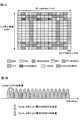
- FIG. 2 is a diagram showing an eSRS mapping example.
- a user terminal maps eSRS to subcarriers shifted between OFDM symbols so that eSRS is mapped to all subcarriers in PRB.
- eSRS is not mapped to the fourth and eleventh OFDM symbols from the left, assuming that PUSCH DM-RSs are arranged in all subcarriers.
- eSRS and PUSCH are not transmitted (multiplexed) in the same subframe, eSRS may be mapped to the fourth and eleventh OFDM symbols from the left.
- the eSRS may not be mapped to the fourth and eleventh OFDM symbols from the left regardless of whether eSRS and PUSCH are transmitted in the same subframe.
- DM-RS includes other eSRS and the like. This is because it is desirable not to superimpose these signals.
- DM-RSs are arranged on all subcarriers in the fourth and eleventh OFDM symbols from the left, but the above control is performed regardless of the arrangement pattern of DM-RSs. It is valid.
- the user terminal transmits eSRS to some subcarriers (here, two sets of two consecutive subcarriers) in a resource block in a specific OFDM symbol (here, four discontinuous OFDM symbols). Map.
- eSRS is mapped to the same subcarrier between specific OFDM symbols, but is not limited thereto.
- the second mode In the second mode, a mapping example between eSRS and PUSCH will be described.
- the user terminal maps eSRS and PUSCH (uplink data signal) to the same OFDM symbol and transmits the same to the radio base station.
- eSRS and PUSCH uplink data signal
- FIG. 3 is a diagram showing an example of mapping between eSRS and PUSCH.
- eSRS is mapped as shown in FIG. 2B, but may be mapped as shown in FIG. 2A, or may be mapped in a pattern other than those shown in FIGS. 2A and 2B.
- the DM-RS arrangement example of PUSCH is not limited to this.
- the user terminal punctures PUSCH based on radio resources (for example, the number of resource elements) to which eSRS is mapped, or , Rate match. Specifically, when the user terminal punctures the PUSCH, the user terminal encodes the uplink data at a predetermined encoding rate when there is no eSRS, and encodes the encoded bit number so that it matches the payload. Puncture or repeat a bit sequence. Then, the user terminal maps the PUSCH to a resource element to which no DMRS is assigned, and then replaces the PUSCH resource element with eSRS.
- radio resources for example, the number of resource elements
- the user terminal when the PUSCH is rate-matched, the user terminal encodes uplink data at a predetermined coding rate, and punctures or repeats the encoded bit sequence so that the number of encoded bits matches the payload. I do. And a user terminal maps the said PUSCH to the resource element to which eSRS and DMRS are not allocated.
- the user terminal receives an L1 / L2 control signal (for example, UL grant) to allocate (grant) PUSCH from the radio base station.
- the L1 / L2 control signal includes allocation PRB information indicating a PRB allocated to the PUSCH (hereinafter referred to as allocation PRB).
- the L1 / L2 control signal may include information on eSRS resource allocation.
- eSRS resource allocation information includes at least one of whether to transmit eSRS, eSRS allocation PRB, OFDM symbol to which eSRS is allocated, eSRS sequence, and orthogonal code index of eSRS sequence. May be shown.
- FIG. 3B shows an eSRS and PUSCH allocation PRB in the system band.
- the eSRS allocation PRB may be different from the PUSCH allocation PRB.
- the eSRS allocation PRB may partially overlap with the PUSCH allocation PRB.
- the eSRS allocation PRB may overlap with the PUSCH allocation PRB as a whole (may be included in the PUSCH allocation PRB) or the same.
- the user terminal may perform PUSCH puncture or rate matching only with the overlapping PRB.
- the third mode In the third mode, an example of mapping between eSRS and PUCCH will be described.
- the user terminal maps eSRS and PUCCH (uplink control signal) to the same OFDM symbol and transmits the same to the radio base station.
- the third aspect can be combined with the first aspect, and the description below will focus on the differences from the first aspect.
- FIG. 4 is a diagram showing an example of mapping between eSRS and PUCCH.
- eSRS is mapped as shown in FIG. 2B, but may be mapped as shown in FIG. 2A, or may be mapped in a pattern other than those shown in FIGS. 2A and 2B.
- the DM-RS arrangement example of PUCCH is not limited to this.
- the user terminal when mapping eSRS and PUCCH in the same PRB, the user terminal punctures PUCCH based on radio resources (for example, the number of resource elements) to which eSRS is mapped, or , Rate match. Specifically, the user terminal encodes uplink control information (UCI: Uplink Control Information) at a predetermined coding rate, and the encoded bit sequence is punctured or matched so that the number of encoded bits matches the payload. Repeat. When puncturing is applied, the user terminal maps the PUCCH to a resource element to which no DM-RS is assigned, and replaces the PUCCH resource element with eSRS. When applying rate matching, the user terminal maps the PUCCH to a resource element to which no eSRS or DMRS is assigned.
- uplink control information UCI: Uplink Control Information
- the user terminal receives an L1 / L2 control signal (for example, DL assignment) instructing transmission of PUCCH from the radio base station.
- L1 / L2 control signal for example, DL assignment
- the PDSCH is assigned by the L1 / L2 control signal, it is required to transmit the PDSCH delivery confirmation information (HARQ-ACK) using the PUCCH.
- the DL assignment for allocating PDSCH can be said to be a kind of L1 / L2 control signal instructing transmission of PUCCH.
- the L1 / L2 control signal may include information related to the above-described eSRS resource allocation (see the second mode).
- FIG. 4B shows an eSRS and PUCCH allocation PRB in the system band.
- the eSRS allocation PRB may be different from the PUCCH allocation PRB.
- the eSRS allocation PRB may partially overlap with the PUCCH allocation PRB.
- the eSRS allocation PRB may overlap with the PUCCH allocation PRB as a whole (may be included in the PUCCH allocation PRB) or the same.
- the PUCCH configuration is not limited to that shown in FIG.
- the user terminal may perform puncture or rate matching of the PUCCH only with the overlapping PRB.
- the information on eSRS resource allocation indicates whether or not to transmit eSRS, eSRS allocation PRB, OFDM symbol to which eSRS is allocated, and at least one of eSRS sequences. Also good.
- the first notification example using both higher layer signaling for example, RRC signaling or broadcast information
- the L1 / L2 control signal for example, PDCCH / EPDCCH
- the L1 / L2 control signal for example, PDCCH / EPDCCH
- the second notification example will be described.
- the first and second notification examples can be combined with the first to third aspects, respectively.
- the user terminal sets at least one candidate resource for eSRS by higher layer signaling.
- the user terminal receives an L1 / L2 control signal including trigger information that triggers a radio resource selected from the set at least one candidate resource.
- a user terminal transmits eSRS using the radio
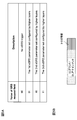
- FIG. 5 is a diagram illustrating an example of eSRS trigger information included in the L1 / L2 control signal.
- the user terminal is configured with three eSRS candidate resources (1 st -3 rd eSRS parameter set) by higher layer signaling.
- the user terminal transmits the eSRS using the candidate resource indicated by the trigger information.
- FIG. 5A shows 2-bit trigger information, the present invention is not limited to this. For example, in the case of 1 bit, one of the candidate resources set by higher layer signaling is triggered.
- the trigger information may be included in an L1 / L2 control signal (for example, UL grant) instructing PUSCH transmission, or an L1 / L2 control signal instructing PUCCH transmission.
- L1 / L2 control signal for example, UL grant
- L1 / L2 control signal instructing PUCCH transmission instructing PUCCH transmission.
- DL assignment since the transmission confirmation information (HARQ-ACK) for the PDSCH is requested to be transmitted on the PUCCH by the DL assignment, the DL assignment can be said to be a kind of L1 / L2 control signal instructing the transmission of the PUCCH.
- the eSRS allocation resource is specified by the L1 / L2 control signal.
- the user terminal receives an L1 / L2 control signal including information on eSRS resource allocation (eSRS allocation information).
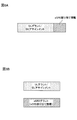
- FIG. 6 is an explanatory diagram of an L1 / L2 control signal including eSRS allocation information.
- the eSRS allocation information may be included in an L1 / L2 control signal (for example, UL grant) instructing PUSCH transmission.
- the user terminal When receiving the L1 / L2 control signal, the user terminal transmits eSRS using the radio resource indicated by the eSRS allocation information, and transmits PUSCH using the radio resource indicated by the UL grant.
- the eSRS allocation information may be included in an L1 / L2 control signal (for example, DL assignment) instructing transmission of PUCCH.
- L1 / L2 control signal for example, DL assignment
- DL assignment is a type of L1 / L2 control signal that instructs transmission of an uplink control signal. I can say that.
- the eSRS allocation information may be provided separately from the UL grant and DL assignment, and may be included in an L1 / L2 control signal (for example, eSRS grant) instructing eSRS transmission. Good.
- L1 / L2 control signal for example, eSRS grant
- the user terminal transmits eSRS using the radio resource indicated by the eSRS allocation information.
- the user terminal receives ZP instruction information (instruction information) instructing whether to zero-pad radio resources allocated to the eSRS, and based on the ZP instruction information, for the resource element of the eSRS Stop mapping (zero padding).
- ZP instruction information instruction information
- the mapping of the PUSCH or PUCCH to the resource element is watched (punctured). Thereby, the interference with respect to eSRS of another user terminal can be reduced.
- FIG. 7 is an explanatory diagram of eSRS zero padding.
- the eSRS allocation position is the same pattern as in FIG. 2B, but it may be the same pattern as in FIG. 2A or a pattern other than those in FIGS. 2A and 2B.
- the eSRS is not mapped to the eSRS allocation resource and is zero-padded (ZP-eSRS: Zero Padded-eSRS). For this reason, the interference which the eSRS of the own terminal gives with respect to eSRS of the other user terminal mapped by the same radio
- FIG. 7B shows an example of PRB allocation to ZP-eSRS and PUSCH in the system band.
- the ZP-eSRS allocation PRB may be different from the PUSCH allocation PRB.
- the ZPR-eSRS allocation PRB may partially overlap with the PUSCH allocation PRB.
- FIG. 8 is an explanatory diagram of the L1 / L2 control signal including the ZP instruction information.
- the ZP instruction information includes the trigger information, It may be included in the UL grant or DL assignment.
- the ZP indication information when the eSRS allocation information is included in the UL grant or DL assignment (second notification example, FIG. 6A), as shown in FIG. 8B, the ZP indication information, together with the eSRS allocation information, the UL grant or It may be included in the DL assignment.
- the ZP instruction information may be included in the UL grant or DL assignment.
- wireless communication system Wireless communication system
- the radio communication method according to each of the above aspects is applied.
- wireless communication method which concerns on each said aspect may be applied independently, respectively, and may be applied in combination.
- FIG. 9 is a diagram illustrating an example of a schematic configuration of a wireless communication system according to an embodiment of the present invention.
- carrier aggregation (CA) and / or dual connectivity (DC) in which a plurality of basic frequency blocks (component carriers) each having a system bandwidth (for example, 20 MHz) of the LTE system as one unit are applied.
- the wireless communication system 1 may be referred to as SUPER 3G, LTE-A (LTE-Advanced), IMT-Advanced, 4G, 5G, FRA (Future Radio Access), or the like.
- the radio communication system 1 shown in FIG. 9 includes a radio base station 11 that forms a macro cell C1, and radio base stations 12a to 12c that are arranged in the macro cell C1 and form a small cell C2 that is narrower than the macro cell C1. . Moreover, the user terminal 20 is arrange
- the user terminal 20 can be connected to both the radio base station 11 and the radio base station 12. It is assumed that the user terminal 20 uses the macro cell C1 and the small cell C2 that use different frequencies simultaneously by CA or DC. In addition, the user terminal 20 can apply CA or DC using a plurality of cells (CC) (for example, six or more CCs).
- CC cells
- Communication between the user terminal 20 and the radio base station 11 can be performed using a carrier having a relatively low frequency band (for example, 2 GHz) and a narrow bandwidth (referred to as an existing carrier or a legacy carrier).
- a carrier having a relatively high frequency band for example, 3.5 GHz, 5 GHz, etc.
- the same carrier may be used.
- the configuration of the frequency band used by each radio base station is not limited to this.
- a wired connection for example, an optical fiber compliant with CPRI (Common Public Radio Interface), an X2 interface, etc.
- a wireless connection It can be set as the structure to do.
- the radio base station 11 and each radio base station 12 are connected to the higher station apparatus 30 and connected to the core network 40 via the higher station apparatus 30.
- the upper station device 30 includes, for example, an access gateway device, a radio network controller (RNC), a mobility management entity (MME), and the like, but is not limited thereto.
- RNC radio network controller
- MME mobility management entity
- Each radio base station 12 may be connected to the higher station apparatus 30 via the radio base station 11.
- the radio base station 11 is a radio base station having a relatively wide coverage, and may be called a macro base station, an aggregation node, an eNB (eNodeB), a transmission / reception point, or the like.
- the radio base station 12 is a radio base station having local coverage, and includes a small base station, a micro base station, a pico base station, a femto base station, a HeNB (Home eNodeB), an RRH (Remote Radio Head), and transmission / reception. It may be called a point.
- the radio base stations 11 and 12 are not distinguished, they are collectively referred to as a radio base station 10.
- Each user terminal 20 is a terminal compatible with various communication methods such as LTE and LTE-A, and may include not only a mobile communication terminal but also a fixed communication terminal.
- OFDMA Orthogonal Frequency Division Multiple Access
- OFDMA is a multi-carrier transmission scheme that performs communication by dividing a frequency band into a plurality of narrow frequency bands (subcarriers) and mapping data to each subcarrier.
- the uplink and downlink radio access methods are not limited to these combinations.
- SC-FDMA single carrier-frequency division multiple access
- SC-FDMA is a single-carrier transmission scheme that reduces interference between terminals by dividing the system bandwidth into bands consisting of one or continuous resource blocks for each terminal and using a plurality of terminals with mutually different bands. is there.
- downlink channels include a downlink shared channel (PDSCH) shared by each user terminal 20, a broadcast channel (PBCH: Physical Broadcast Channel), a downlink L1 / L2 control channel, and the like. Used. User data, higher layer control information, SIB (System Information Block), etc. are transmitted by PDSCH. Also, MIB (Master Information Block) is transmitted by PBCH.
- PDSCH downlink shared channel
- PBCH Physical Broadcast Channel
- SIB System Information Block
- MIB Master Information Block
- Downlink L1 / L2 control channels include downlink control channels (PDCCH (Physical Downlink Control Channel), EPDCCH (Enhanced Physical Downlink Control Channel)), PCFICH (Physical Control Format Indicator Channel), PHICH (Physical Hybrid-ARQ Indicator Channel), etc. Including. Downlink control information (DCI: Downlink Control Information) including scheduling information of PDSCH and PUSCH is transmitted by PDCCH. The number of OFDM symbols used for PDCCH is transmitted by PCFICH. The HAICH transmission confirmation information (ACK / NACK) for PUSCH is transmitted by PHICH.
- EPDCCH is frequency-division multiplexed with PDSCH (downlink shared data channel), and is used for transmission of DCI and the like in the same manner as PDCCH.
- an uplink shared channel shared by each user terminal 20
- an uplink control channel PUCCH: Physical Uplink Control Channel
- PRACH Physical Random Access Channel
- User data and higher layer control information are transmitted by the PUSCH.
- Uplink control information including at least one of delivery confirmation information (ACK / NACK) and radio quality information (CQI) is transmitted by PUSCH or PUCCH.
- a random access preamble for establishing connection with a cell is transmitted by the PRACH.
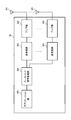
- FIG. 10 is a diagram illustrating an example of the overall configuration of a radio base station according to an embodiment of the present invention.
- the radio base station 10 includes a plurality of transmission / reception antennas 101, an amplifier unit 102, a transmission / reception unit 103, a baseband signal processing unit 104, a call processing unit 105, and a transmission path interface 106.
- each of the transmission / reception antenna 101, the amplifier unit 102, and the transmission / reception unit 103 may be configured to include one or more.
- User data transmitted from the radio base station 10 to the user terminal 20 via the downlink is input from the higher station apparatus 30 to the baseband signal processing unit 104 via the transmission path interface 106.
- PDCP Packet Data Convergence Protocol
- RLC Radio Link Control
- MAC Medium Access
- Retransmission control for example, HARQ (Hybrid Automatic Repeat reQuest) transmission processing
- HARQ Hybrid Automatic Repeat reQuest
- the downlink control signal is also subjected to transmission processing such as channel coding and inverse fast Fourier transform, and is transferred to the transmission / reception unit 103.
- the transmission / reception unit 103 converts the baseband signal output by precoding for each antenna from the baseband signal processing unit 104 to a radio frequency band and transmits the converted signal.
- the radio frequency signal frequency-converted by the transmission / reception unit 103 is amplified by the amplifier unit 102 and transmitted from the transmission / reception antenna 101.
- the transmission / reception unit 103 may transmit information indicating at least one candidate resource by higher layer signaling. Further, the transmission / reception unit 103 may transmit trigger information that triggers a radio resource selected from at least one candidate resource set by higher layer signaling by physical layer signaling.
- the transmission / reception unit 103 transmits eSRS allocation information indicating radio resources allocated to the eSRS.
- the eSRS allocation information includes an uplink grant instructing transmission of an uplink data signal, a downlink assignment instructing transmission of an uplink control signal including delivery confirmation information for the downlink data signal, or transmission of the measurement reference signal. May be included in the instructing grant.
- the transmission / reception unit 103 may transmit ZP instruction information indicating whether or not to perform zero padding of radio resources allocated to eSRS.
- the ZP instruction information may be included in an uplink grant instructing transmission of an uplink data signal or a downlink assignment instructing transmission of an uplink control signal including delivery confirmation information for the downlink data signal.
- the transmitter / receiver, the transmission / reception circuit, or the transmission / reception device can be configured based on common recognition in the technical field according to the present invention.
- the transmission / reception part 103 may be comprised as an integral transmission / reception part, and may be comprised from a transmission part and a receiving part.
- the radio frequency signal received by the transmission / reception antenna 101 is amplified by the amplifier unit 102.
- the transmission / reception unit 103 receives the uplink signal amplified by the amplifier unit 102.
- the transmission / reception unit 103 converts the frequency of the received signal into a baseband signal and outputs it to the baseband signal processing unit 104.
- the baseband signal processing unit 104 performs Fast Fourier Transform (FFT) processing, Inverse Discrete Fourier Transform (IDFT) processing, and error correction on user data included in the input upstream signal. Decoding, MAC retransmission control reception processing, RLC layer and PDCP layer reception processing are performed and transferred to the upper station apparatus 30 via the transmission path interface 106.
- the call processing unit 105 performs call processing such as communication channel setting and release, state management of the radio base station 10, and radio resource management.
- the transmission path interface 106 transmits and receives signals to and from the higher station apparatus 30 via a predetermined interface.
- the transmission path interface 106 transmits and receives (backhaul signaling) signals to and from the adjacent radio base station 10 via an interface between base stations (for example, an optical fiber compliant with CPRI (Common Public Radio Interface), X2 interface). Also good.
- CPRI Common Public Radio Interface
- X2 interface also good.
- FIG. 11 is a diagram illustrating an example of a functional configuration of the radio base station according to the present embodiment.
- FIG. 11 mainly shows functional blocks of characteristic portions in the present embodiment, and the wireless base station 10 also has other functional blocks necessary for wireless communication.
- the baseband signal processing unit 104 includes a control unit 301, a transmission signal generation unit 302, a mapping unit 303, a reception signal processing unit 304, and a measurement unit 305.
- the control unit 301 controls the entire radio base station 10.
- the control unit 301 controls, for example, downlink signal generation by the transmission signal generation unit 302, signal mapping by the mapping unit 303, and signal reception processing by the reception signal processing unit 304.
- control unit 301 performs downlink (DL) signal transmission control (for example, modulation scheme, coding rate, resource allocation (scheduling)) based on channel state information (CSI) reported from the user terminal 20. Control).
- DL downlink
- CSI channel state information
- control unit 301 may perform beam control of a downlink signal to which FD-MIMO is applied based on a measurement result using eSRS (measurement reference signal) in the measurement unit 305.
- eSRS measurement reference signal
- the control unit 301 can be configured by a controller, a control circuit, or a control device described based on common recognition in the technical field according to the present invention.
- the transmission signal generation unit 302 generates a DL signal (including a downlink data signal and a downlink control signal) based on an instruction from the control unit 301 and outputs the DL signal to the mapping unit 303. Specifically, the transmission signal generation unit 302 generates a downlink data signal (PDSCH) including notification information and user data by the above-described higher layer signaling and outputs the downlink data signal (PDSCH) to the mapping unit 303. Also, the transmission signal generation unit 302 generates a downlink control signal (PDCCH / EPDCCH) including the above-described DCI, and outputs it to the mapping unit 303. Also, the transmission signal generation unit 302 generates downlink reference signals such as CRS and CSI-RS, and outputs them to the mapping unit 303.
- PDSCH downlink data signal
- PDSCH downlink data signal
- EPDCCH downlink control signal
- the transmission signal generation unit 302 generates downlink reference signals such as CRS and CSI-RS, and outputs them to the mapping
- the transmission signal generation unit 302 can be a signal generator, a signal generation circuit, or a signal generation device described based on common recognition in the technical field according to the present invention.
- the mapping unit 303 maps the DL signal generated by the transmission signal generation unit 302 to a predetermined radio resource based on an instruction from the control unit 301, and outputs the DL signal to the transmission / reception unit 103.
- the mapping unit 303 can be a mapper, a mapping circuit, or a mapping device described based on common recognition in the technical field according to the present invention.
- the reception signal processing unit 304 performs reception processing (for example, demapping, demodulation, decoding, etc.) on the UL signal transmitted from the user terminal 20.
- the processing result is output to the control unit 301.
- the reception signal processing unit 304 may be configured by a signal processor, a signal processing circuit or a signal processing device, and a measuring device, a measurement circuit or a measuring device, which are described based on common recognition in the technical field according to the present invention. it can.
- the measurement unit 305 performs measurement using a reference signal (for example, existing SRS or eSRS) from the user terminal 20 and outputs the measurement result to the control unit 301. Specifically, the measurement unit 305 uses the eSRS (measurement reference signal) transmitted from the user terminal 20 to which UL-OFDMA is applied, and uses the uplink propagation quality or the downlink using the channel reciprocity. Measure the channel state.
- a reference signal for example, existing SRS or eSRS
- eSRS measurement reference signal
- the measuring unit 305 can be composed of a signal processor, a signal processing circuit or a signal processing device, and a measuring device, a measuring circuit or a measuring device which are explained based on common recognition in the technical field according to the present invention.
- FIG. 12 is a diagram illustrating an example of the overall configuration of a user terminal according to an embodiment of the present invention.
- the user terminal 20 includes a plurality of transmission / reception antennas 201 for MIMO transmission, an amplifier unit 202, a transmission / reception unit 203, a baseband signal processing unit 204, and an application unit 205.
- the radio frequency signals received by the plurality of transmission / reception antennas 201 are each amplified by the amplifier unit 202.
- Each transmitting / receiving unit 203 receives the downlink signal amplified by the amplifier unit 202.
- the transmission / reception unit 203 converts the frequency of the received signal into a baseband signal and outputs it to the baseband signal processing unit 204.
- the baseband signal processing unit 204 performs FFT processing, error correction decoding, retransmission control reception processing, and the like on the input baseband signal.
- the downlink user data is transferred to the application unit 205.
- the application unit 205 performs processing related to layers higher than the physical layer and the MAC layer.
- broadcast information in the downlink data is also transferred to the application unit 205.
- uplink user data is input from the application unit 205 to the baseband signal processing unit 204.
- the baseband signal processing unit 204 performs retransmission control transmission processing (for example, HARQ transmission processing), channel coding, precoding, discrete Fourier transform (DFT) processing, IFFT processing, and the like. It is transferred to the transmission / reception unit 203.
- the transmission / reception unit 203 converts the baseband signal output from the baseband signal processing unit 204 into a radio frequency band and transmits it.
- the radio frequency signal frequency-converted by the transmission / reception unit 203 is amplified by the amplifier unit 202 and transmitted from the transmission / reception antenna 201.
- the transmission / reception unit 203 may receive trigger information that triggers a radio resource selected from at least one candidate resource set by higher layer signaling (FIG. 5).
- the trigger information may be included in an uplink grant instructing transmission of an uplink data signal or a downlink assignment instructing transmission of an uplink control signal including delivery confirmation information for a downlink data signal.
- the transmission / reception unit 203 may receive eSRS allocation information (allocation information) indicating radio resources allocated to the eSRS (FIG. 6).
- the eSRS allocation information includes an uplink grant instructing transmission of an uplink data signal, a downlink assignment instructing transmission of an uplink control signal including delivery confirmation information for the downlink data signal, or transmission of the measurement reference signal. Included in the instructing grant.
- the transmission / reception unit 203 may receive ZP instruction information (instruction information) instructing whether to zero-pad radio resources allocated to the eSRS (FIG. 8).
- the ZP instruction information may be included in an uplink grant instructing transmission of an uplink data signal or a downlink assignment instructing transmission of an uplink control signal including delivery confirmation information for the downlink data signal.
- the transmission / reception unit 203 can be a transmitter / receiver, a transmission / reception circuit, or a transmission / reception device described based on common recognition in the technical field according to the present invention. Further, the transmission / reception unit 203 may be configured as an integral transmission / reception unit, or may be configured from a transmission unit and a reception unit.
- FIG. 13 is a diagram illustrating an example of a functional configuration of the user terminal according to the present embodiment. Note that FIG. 13 mainly shows functional blocks of characteristic portions in the present embodiment, and the user terminal 20 also has other functional blocks necessary for wireless communication. As illustrated in FIG. 13, the baseband signal processing unit 204 included in the user terminal 20 includes a control unit 401, a transmission signal generation unit 402, a mapping unit 403, a reception signal processing unit 404, and a measurement unit 405. I have.
- the control unit 401 controls the entire user terminal 20.
- the control unit 401 controls, for example, signal generation by the transmission signal generation unit 402, signal mapping by the mapping unit 403, and signal reception processing by the reception signal processing unit 404.
- control unit 401 controls the mapping unit 403 to map eSRS to radio resources that are discontinuous in the time direction and / or the frequency direction.
- the control unit 401 performs control so that the eSRS is mapped to all subcarriers in the PRB.
- control unit 401 may perform control so as to map eSRS to subcarriers shifted between OFDM symbols (FIG. 2A).
- control unit 401 controls to map eSRS to some subcarriers in the PRB in a specific OFDM symbol (FIG. 2B).
- control unit 401 performs control to map eSRS and PUSCH or PUCCH to the same OFDM symbol (FIGS. 3 and 4). In this case, the control unit 401 may control the transmission signal generation unit 402 to perform PUSCH or PUCCH puncture or rate matching based on the eSRS allocation resource.
- control unit 401 may perform control so as to map the eSRS to a radio resource triggered by the trigger information received by the transmission / reception unit 203 (FIG. 5). Alternatively, the control unit 401 may perform control so as to map the eSRS to the radio resource indicated by the eSRS allocation information received by the transmission / reception unit 203 (FIG. 6).
- control unit 401 may cancel (zero padding) the mapping of the eSRS to the radio resource indicated by the eSRS allocation information based on the ZP instruction information received by the transmission / reception unit 203.
- the control unit 401 can be configured by a controller, a control circuit, or a control device described based on common recognition in the technical field according to the present invention.
- the transmission signal generation unit 402 generates a UL signal (including an uplink data signal and an uplink control signal) based on an instruction from the control unit 401 and outputs the UL signal to the mapping unit 403. For example, the transmission signal generation unit 402 generates an uplink control signal (PUCCH) including UCI (at least one of HARQ-ACK, CQI, and SR).
- PUCCH uplink control signal
- the transmission signal generation unit 402 generates eSRS (measurement reference signal) used for measurement in the radio base station 10.
- the transmission signal generation unit 402 may generate an eSRS sequence using a CAZAC (Constant Amplitude Zero Auto-Correlation) sequence in the same manner as an existing SRS, or an eSRS using a sequence other than the CAZAC sequence. A sequence may be generated.
- CAZAC Constant Amplitude Zero Auto-Correlation
- the transmission signal generation unit 402 generates a sequence generated by masking a PN (Pseudo-Noise) sequence with a cell ID or a virtual cell ID as an eSRS sequence, or the sequence is PSK (Phase Shift Keying) modulation (for example, BPSK). (Binary PSK) or QPSK (Quadrature PSK)) may be generated.
- PSK Phase Shift Keying
- the transmission signal generation unit 402 can be a signal generator, a signal generation circuit, or a signal generation device described based on common recognition in the technical field according to the present invention.
- the mapping unit 403 Based on an instruction from the control unit 401, the mapping unit 403 maps the UL signal (uplink control signal, uplink data signal, eSRS, SRS, etc.) generated by the transmission signal generation unit 402 to a radio resource, and transmits and receives It outputs to 203.
- the mapping unit 403 may be a mapper, a mapping circuit, or a mapping device described based on common recognition in the technical field according to the present invention.
- the reception signal processing unit 404 performs reception processing (for example, demapping, demodulation, decoding, etc.) on the DL signal (including the downlink control signal and the downlink data signal).
- the reception signal processing unit 404 outputs information received from the radio base station 10 to the control unit 401.
- the received signal processing unit 404 outputs, for example, broadcast information, system information, control information by higher layer signaling such as RRC signaling, DCI, and the like to the control unit 401.
- the received signal processing unit 404 can be configured by a signal processor, a signal processing circuit, or a signal processing device described based on common recognition in the technical field according to the present invention. Further, the reception signal processing unit 404 can constitute a reception unit according to the present invention.
- the measurement unit 405 measures the channel state based on a reference signal (for example, CSI-RS) from the radio base station 10 and outputs the measurement result to the control unit 401. Note that the channel state measurement may be performed for each CC.
- a reference signal for example, CSI-RS
- the measuring unit 405 can be composed of a signal processor, a signal processing circuit or a signal processing device, and a measuring device, a measurement circuit or a measuring device which are explained based on common recognition in the technical field according to the present invention.
- each functional block is realized by one physically coupled device, or may be realized by two or more physically separated devices connected by wire or wirelessly and by a plurality of these devices. Good.
- the radio base station 10 and the user terminal 20 are realized using hardware such as ASIC (Application Specific Integrated Circuit), PLD (Programmable Logic Device), and FPGA (Field Programmable Gate Array). May be.
- the radio base station 10 and the user terminal 20 are each a computer device including a processor (CPU: Central Processing Unit), a communication interface for network connection, a memory, and a computer-readable storage medium holding a program. It may be realized. That is, the radio base station, user terminal, and the like according to an embodiment of the present invention may function as a computer that performs processing of the radio communication method according to the present invention.
- Computer-readable recording media include, for example, flexible disks, magneto-optical disks, ROM (Read Only Memory), EPROM (Erasable Programmable ROM), CD-ROM (Compact Disc-ROM), RAM (Random Access Memory), A storage medium such as a hard disk.
- the program may be transmitted from a network via a telecommunication line.
- the radio base station 10 and the user terminal 20 may include an input device such as an input key and an output device such as a display.
- the functional configurations of the radio base station 10 and the user terminal 20 may be realized by the hardware described above, may be realized by a software module executed by a processor, or may be realized by a combination of both.
- the processor controls the entire user terminal by operating an operating system. Further, the processor reads programs, software modules and data from the storage medium into the memory, and executes various processes according to these.
- the program may be a program that causes a computer to execute the operations described in the above embodiments.
- the control unit 401 of the user terminal 20 may be realized by a control program stored in a memory and operated by a processor, and may be realized similarly for other functional blocks.
- software, instructions, etc. may be transmitted / received via a transmission medium.
- software may use websites, servers, or other devices using wired technology such as coaxial cable, fiber optic cable, twisted pair and digital subscriber line (DSL) and / or wireless technology such as infrared, wireless and microwave.
- wired technology such as coaxial cable, fiber optic cable, twisted pair and digital subscriber line (DSL) and / or wireless technology such as infrared, wireless and microwave.
- DSL digital subscriber line
- wireless technology such as infrared, wireless and microwave.
- the channel and / or symbol may be a signal (signaling).
- the signal may be a message.
- the component carrier (CC) may be called a carrier frequency, a cell, or the like.
- information, parameters, and the like described in this specification may be represented by absolute values, may be represented by relative values from a predetermined value, or may be represented by other corresponding information.
- the radio resource may be indicated by an index.
- notification of predetermined information is not limited to explicitly performed, but is performed implicitly (for example, by not performing notification of the predetermined information). May be.
- notification of information is not limited to the aspect / embodiment described in this specification, and may be performed by other methods.
- notification of information includes physical layer signaling (for example, DCI (Downlink Control Information), UCI (Uplink Control Information)), upper layer signaling (for example, RRC (Radio Resource Control) signaling, MAC (Medium Access Control) signaling), It may be implemented by broadcast information (MIB (Master Information Block), SIB (System Information Block)), other signals, or a combination thereof.
- the RRC signaling may be referred to as an RRC message, and may be, for example, an RRC connection setup (RRCConnectionSetup) message, an RRC connection reconfiguration (RRCConnectionReconfiguration) message, or the like.
- Each aspect / embodiment described in this specification includes LTE (Long Term Evolution), LTE-A (LTE-Advanced), SUPER 3G, IMT-Advanced, 4G, 5G, FRA (Future Radio Access), CDMA2000, UMB (Ultra Mobile Broadband), IEEE 802.11 (Wi-Fi), IEEE 802.16 (WiMAX), IEEE 802.20, UWB (Ultra-WideBand), Bluetooth (registered trademark), and other appropriate systems
- LTE Long Term Evolution
- LTE-A LTE-Advanced
- SUPER 3G IMT-Advanced
- 4G 5G
- FRA Full Radio Access
- CDMA2000 Code Division Multiple Access 2000
- UMB User Mobile Broadband
- IEEE 802.11 Wi-Fi
- IEEE 802.16 WiMAX
- IEEE 802.20 UWB (Ultra-WideBand)
- Bluetooth registered trademark
Landscapes
- Engineering & Computer Science (AREA)
- Signal Processing (AREA)
- Computer Networks & Wireless Communication (AREA)
- Mobile Radio Communication Systems (AREA)
Abstract
Description
第1の態様では、eSRSの生成及びマッピング例について説明する。第1の態様において、ユーザ端末は、無線基地局における測定に用いられるeSRS(測定用参照信号)を生成し、時間方向及び/又は周波数方向で不連続の無線リソース(例えば、サブキャリア、リソースブロック(PRB:Physical Resource Block)、OFDMシンボル、サブフレームなど)に対して、eSRSをマッピングする。 (First aspect)
In the first aspect, an eSRS generation and mapping example will be described. In the first aspect, the user terminal generates eSRS (measurement reference signal) used for measurement in the radio base station, and discontinuous radio resources (eg, subcarriers, resource blocks) in the time direction and / or the frequency direction. The eSRS is mapped to (PRB: Physical Resource Block), OFDM symbol, subframe, etc.).
第2の態様では、eSRSとPUSCHとのマッピング例について説明する。第2の態様において、ユーザ端末は、同一のOFDMシンボルに対してeSRSとPUSCH(上りデータ信号)とをマッピングして、無線基地局に送信する。第2の態様は、第1の態様と組み合わせることが可能であり、以下では、第1の態様との相違点を中心に説明する。 (Second aspect)
In the second mode, a mapping example between eSRS and PUSCH will be described. In the second aspect, the user terminal maps eSRS and PUSCH (uplink data signal) to the same OFDM symbol and transmits the same to the radio base station. The second aspect can be combined with the first aspect, and the description below will focus on the differences from the first aspect.
第3の態様では、eSRSとPUCCHとのマッピング例について説明する。第3の態様において、ユーザ端末は、同一のOFDMシンボルに対してeSRSとPUCCH(上り制御信号)とをマッピングして、無線基地局に送信する。第3の態様は、第1の態様と組み合わせることが可能であり、以下では、第1の態様との相違点を中心に説明する。 (Third aspect)
In the third mode, an example of mapping between eSRS and PUCCH will be described. In the third aspect, the user terminal maps eSRS and PUCCH (uplink control signal) to the same OFDM symbol and transmits the same to the radio base station. The third aspect can be combined with the first aspect, and the description below will focus on the differences from the first aspect.
第4の態様では、eSRSのリソース割り当てに関する情報の通知例について詳細に説明する。第2及び第3の態様で説明したように、eSRSのリソース割り当てに関する情報は、eSRSを送信するか否か、eSRSの割り当てPRB、eSRSが割り当てられるOFDMシンボル、eSRS系列の少なくとも一つを示してもよい。 (Fourth aspect)
In the fourth aspect, a notification example of information related to resource allocation of eSRS will be described in detail. As described in the second and third aspects, the information on eSRS resource allocation indicates whether or not to transmit eSRS, eSRS allocation PRB, OFDM symbol to which eSRS is allocated, and at least one of eSRS sequences. Also good.
第1の通知例では、ユーザ端末は、上位レイヤシグナリングによりeSRSの少なくとも一つの候補リソースを設定する。ユーザ端末は、設定された少なくとも一つの候補リソースから選択される無線リソースをトリガするトリガ情報を含むL1/L2制御信号を受信する。ユーザ端末は、トリガ情報により指定される無線リソースを用いてeSRSを送信する。 <First notification example>
In the first notification example, the user terminal sets at least one candidate resource for eSRS by higher layer signaling. The user terminal receives an L1 / L2 control signal including trigger information that triggers a radio resource selected from the set at least one candidate resource. A user terminal transmits eSRS using the radio | wireless resource designated with trigger information.
第2の通知例では、L1/L2制御信号により、eSRSの割り当てリソースが指定される。具体的には、ユーザ端末は、eSRSのリソース割り当てに関する情報(eSRS割り当て情報)を含むL1/L2制御信号を受信する。 <Second notification example>
In the second notification example, the eSRS allocation resource is specified by the L1 / L2 control signal. Specifically, the user terminal receives an L1 / L2 control signal including information on eSRS resource allocation (eSRS allocation information).
第5の態様では、eSRSのゼロパディング(ZP:Zero-Padding)について説明する。第5の態様では、ユーザ端末は、eSRSに割り当てられる無線リソースをゼロパディングするか否かを指示するZP指示情報(指示情報)を受信し、前記ZP指示情報に基づいてeSRSの当該リソースエレメントに対するマッピングを中止する(ゼロパディングする)。同様に、前記ZP指示情報に基づいて、PUSCHまたはPUCCHの送信がある場合、PUSCHまたはPUCCHの当該リソースエレメントに対するマッピングを注視する(パンクチャする)。これにより、他のユーザ端末のeSRSに対する干渉を低減できる。 (5th aspect)
In the fifth aspect, zero padding (ZP: Zero-Padding) of eSRS will be described. In the fifth aspect, the user terminal receives ZP instruction information (instruction information) instructing whether to zero-pad radio resources allocated to the eSRS, and based on the ZP instruction information, for the resource element of the eSRS Stop mapping (zero padding). Similarly, when there is PUSCH or PUCCH transmission based on the ZP instruction information, the mapping of the PUSCH or PUCCH to the resource element is watched (punctured). Thereby, the interference with respect to eSRS of another user terminal can be reduced.
以下、本発明の一実施形態に係る無線通信システムの構成について説明する。この無線通信システムでは、上記各態様に係る無線通信方法が適用される。なお、上記各態様に係る無線通信方法は、それぞれ単独で適用されてもよいし、組み合わせて適用されてもよい。 (Wireless communication system)
Hereinafter, the configuration of a wireless communication system according to an embodiment of the present invention will be described. In this radio communication system, the radio communication method according to each of the above aspects is applied. In addition, the radio | wireless communication method which concerns on each said aspect may be applied independently, respectively, and may be applied in combination.
図10は、本発明の一実施形態に係る無線基地局の全体構成の一例を示す図である。無線基地局10は、複数の送受信アンテナ101と、アンプ部102と、送受信部103と、ベースバンド信号処理部104と、呼処理部105と、伝送路インターフェース106とを備えている。なお、送受信アンテナ101、アンプ部102、送受信部103は、それぞれ1つ以上を含むように構成されてもよい。 <Wireless base station>
FIG. 10 is a diagram illustrating an example of the overall configuration of a radio base station according to an embodiment of the present invention. The
図12は、本発明の一実施形態に係るに係るユーザ端末の全体構成の一例を示す図である。ユーザ端末20は、MIMO伝送のための複数の送受信アンテナ201と、アンプ部202と、送受信部203と、ベースバンド信号処理部204と、アプリケーション部205と、を備えている。 <User terminal>
FIG. 12 is a diagram illustrating an example of the overall configuration of a user terminal according to an embodiment of the present invention. The
This application is based on Japanese Patent Application No. 2015-164187 filed on August 21, 2015. All this content is included here.
Claims (10)
- 上りリンクに直交周波数分割多元接続(OFDMA)を適用するユーザ端末であって、
無線基地局における測定に用いられる測定用参照信号を生成する生成部と、
時間方向及び/又は周波数方向で不連続の無線リソースに対して、前記測定用参照信号をマッピングするマッピング部と、
前記測定用参照信号を前記無線基地局に送信する送信部と、
を具備することを特徴とするユーザ端末。 A user terminal that applies orthogonal frequency division multiple access (OFDMA) to the uplink,
A generator for generating a reference signal for measurement used for measurement in a radio base station;
A mapping unit that maps the measurement reference signal to radio resources that are discontinuous in the time direction and / or the frequency direction;
A transmitter for transmitting the measurement reference signal to the radio base station;
A user terminal comprising: - 前記マッピング部は、リソースブロック内の全サブキャリアに前記測定用参照信号がマッピングされるように、直交周波数分割多重(OFDM)シンボル間でシフトされるサブキャリアに、前記測定用参照信号をマッピングすることを特徴とする請求項1に記載のユーザ端末。 The mapping unit maps the measurement reference signal to subcarriers shifted between orthogonal frequency division multiplexing (OFDM) symbols so that the measurement reference signal is mapped to all subcarriers in a resource block. The user terminal according to claim 1.
- 前記マッピング部は、特定の直交周波数分割多重(OFDM)シンボルにおいて、リソースブロック内の一部のサブキャリアに、前記測定用参照信号をマッピングすることを特徴とする請求項1に記載のユーザ端末。 2. The user terminal according to claim 1, wherein the mapping unit maps the measurement reference signal to some subcarriers in a resource block in a specific orthogonal frequency division multiplexing (OFDM) symbol.
- 前記マッピング部は、同一のOFDMシンボルに対して、前記測定用参照信号と、上りデータ信号又は上り制御信号とをマッピングし、
前記送信部は、前記測定用参照信号と、前記上りデータ信号又は前記上り制御信号とを、同一のOFDMシンボルで前記無線基地局に送信することを特徴とする請求項2又は請求項3に記載のユーザ端末。 The mapping unit maps the measurement reference signal and an uplink data signal or an uplink control signal to the same OFDM symbol,
The said transmission part transmits the said reference signal for a measurement and the said uplink data signal or the said uplink control signal to the said wireless base station by the same OFDM symbol, The Claim 2 or Claim 3 characterized by the above-mentioned. User terminal. - 上位レイヤシグナリングにより設定される少なくとも一つの候補リソースから選択される無線リソースをトリガするトリガ情報を受信する受信部を更に具備し、
前記マッピング部は、前記トリガ情報によりトリガされる無線リソースに、前記測定用参照信号をマッピングすることを特徴とする請求項1から請求項4のいずれかに記載のユーザ端末。 A receiver for receiving trigger information for triggering a radio resource selected from at least one candidate resource set by higher layer signaling;
The user terminal according to any one of claims 1 to 4, wherein the mapping unit maps the measurement reference signal to a radio resource triggered by the trigger information. - 前記測定用参照信号に割り当てられる無線リソースを示す割り当て情報を受信する受信部を更に具備し、
前記マッピング部は、前記割り当て情報が示す無線リソースに、前記測定用参照信号をマッピングすることを特徴とする請求項1から請求項4のいずれかに記載のユーザ端末。 A receiver for receiving allocation information indicating radio resources allocated to the measurement reference signal;
The said mapping part maps the said reference signal for a measurement to the radio | wireless resource which the said allocation information shows, The user terminal in any one of Claims 1-4 characterized by the above-mentioned. - 前記割り当て情報は、上りデータ信号の送信を指示する上りグラント、又は、下りデータ信号に対する送達確認情報を含む上り制御信号の送信を指示する下りアサインメント、又は、前記測定用参照信号の送信を指示するグラントに含まれることを特徴とする請求項6に記載のユーザ端末。 The allocation information is an uplink grant instructing transmission of an uplink data signal, a downlink assignment instructing transmission of an uplink control signal including acknowledgment information for a downlink data signal, or transmission of the reference signal for measurement The user terminal according to claim 6, wherein the user terminal is included in a grant.
- 前記測定用参照信号に割り当てられる無線リソースをゼロパディングするか否かを指示する指示情報を受信する受信部を更に具備し、
前記マッピング部は、前記指示情報に基づいて、前記無線リソースに対する前記測定用参照信号のマッピングを中止することを特徴とする請求項5から請求項7のいずれかに記載のユーザ端末。 A receiving unit for receiving instruction information for instructing whether to zero-pad radio resources allocated to the measurement reference signal;
8. The user terminal according to claim 5, wherein the mapping unit stops mapping the reference signal for measurement to the radio resource based on the instruction information. 9. - 上りリンクに直交周波数分割多元接続(OFDMA)を適用する無線基地局であって、
ユーザ端末から送信される測定用参照信号を受信する受信部と、
前記測定用参照信号を用いて、測定を行う測定部と、を具備し、
前記測定用参照信号は、時間方向及び/又は周波数方向で不連続の無線リソースに対して、マッピングされることを特徴とする無線基地局。 A radio base station that applies orthogonal frequency division multiple access (OFDMA) to the uplink,
A receiving unit for receiving a measurement reference signal transmitted from the user terminal;
A measurement unit that performs measurement using the reference signal for measurement, and
The radio base station, wherein the measurement reference signal is mapped to radio resources that are discontinuous in a time direction and / or a frequency direction. - 上りリンクに直交周波数分割多元接続(OFDMA)を適用するユーザ端末と無線基地局との無線通信方法であって、前記ユーザ端末において、
無線基地局における測定に用いられる測定用参照信号を生成する工程と、
時間方向及び/又は周波数方向で不連続の無線リソースに対して、前記測定用参照信号をマッピングする工程と、
前記測定用参照信号を前記無線基地局に送信する工程と、
を具備することを特徴とする無線通信方法。 A wireless communication method between a user terminal and a radio base station applying orthogonal frequency division multiple access (OFDMA) to an uplink, wherein the user terminal includes:
Generating a reference signal for measurement used for measurement in the radio base station;
Mapping the measurement reference signal to radio resources that are discontinuous in the time direction and / or the frequency direction;
Transmitting the measurement reference signal to the radio base station;
A wireless communication method comprising:
Priority Applications (4)
| Application Number | Priority Date | Filing Date | Title |
|---|---|---|---|
| JP2017536752A JPWO2017033778A1 (en) | 2015-08-21 | 2016-08-12 | User terminal, radio base station, and radio communication method |
| CN201680048333.9A CN107926015B (en) | 2015-08-21 | 2016-08-12 | User terminal, radio base station, and radio communication method |
| EP16839125.8A EP3340709A4 (en) | 2015-08-21 | 2016-08-12 | User terminal, wireless base station, and wireless communication method |
| US15/753,197 US11088790B2 (en) | 2015-08-21 | 2016-08-12 | User terminal, radio base station, and radio communication method |
Applications Claiming Priority (2)
| Application Number | Priority Date | Filing Date | Title |
|---|---|---|---|
| JP2015164187 | 2015-08-21 | ||
| JP2015-164187 | 2015-08-21 |
Publications (1)
| Publication Number | Publication Date |
|---|---|
| WO2017033778A1 true WO2017033778A1 (en) | 2017-03-02 |
Family
ID=58100143
Family Applications (1)
| Application Number | Title | Priority Date | Filing Date |
|---|---|---|---|
| PCT/JP2016/073796 WO2017033778A1 (en) | 2015-08-21 | 2016-08-12 | User terminal, wireless base station, and wireless communication method |
Country Status (5)
| Country | Link |
|---|---|
| US (1) | US11088790B2 (en) |
| EP (1) | EP3340709A4 (en) |
| JP (2) | JPWO2017033778A1 (en) |
| CN (1) | CN107926015B (en) |
| WO (1) | WO2017033778A1 (en) |
Cited By (3)
| Publication number | Priority date | Publication date | Assignee | Title |
|---|---|---|---|---|
| JP6685485B1 (en) * | 2019-08-22 | 2020-04-22 | 三菱電機株式会社 | Transmitter, receiver, communication device, wireless communication system, control circuit, and storage medium |
| JP2020512751A (en) * | 2017-03-24 | 2020-04-23 | クアルコム,インコーポレイテッド | Techniques for multi-cluster uplink transmission |
| JP2020522161A (en) * | 2017-05-26 | 2020-07-27 | オッポ広東移動通信有限公司Guangdong Oppo Mobile Telecommunications Corp., Ltd. | Upstream signal transmission method, terminal and network device |
Families Citing this family (7)
| Publication number | Priority date | Publication date | Assignee | Title |
|---|---|---|---|---|
| US11160072B2 (en) * | 2016-03-31 | 2021-10-26 | Panasonic Intellectual Property Corporalion of America | Special subframe configuration for latency reduction |
| US10374768B2 (en) * | 2017-10-02 | 2019-08-06 | Telefonaktiebolaget Lm Ericsson (Publ) | Efficient SRS resource indication methods |
| WO2019203187A1 (en) * | 2018-04-18 | 2019-10-24 | 株式会社Nttドコモ | User terminal and wireless communication method |
| CN108848482B (en) * | 2018-06-12 | 2021-03-16 | 南京邮电大学 | Resource allocation method based on mMTC layered access framework |
| WO2020021640A1 (en) * | 2018-07-24 | 2020-01-30 | 株式会社Nttドコモ | User device and base station device |
| CN110891312B (en) * | 2018-09-10 | 2023-11-03 | 华为技术有限公司 | Information sending method, information receiving method and device |
| EP4044539A4 (en) * | 2019-10-10 | 2023-06-28 | Ntt Docomo, Inc. | Terminal and wireless communication method |
Citations (3)
| Publication number | Priority date | Publication date | Assignee | Title |
|---|---|---|---|---|
| JP2013515427A (en) * | 2010-01-07 | 2013-05-02 | サムスン エレクトロニクス カンパニー リミテッド | Apparatus and method for improving the characteristics of uplink reference signals |
| JP2013219501A (en) * | 2012-04-06 | 2013-10-24 | Ntt Docomo Inc | Communication system, mobile terminal, local area base station device and communication method |
| WO2014089782A1 (en) * | 2012-12-12 | 2014-06-19 | Broadcom Corporation | Design and signaling for enhanced srs |
Family Cites Families (21)
| Publication number | Priority date | Publication date | Assignee | Title |
|---|---|---|---|---|
| US7773535B2 (en) * | 2004-08-12 | 2010-08-10 | Motorola, Inc. | Method and apparatus for closed loop transmission |
| KR101265632B1 (en) * | 2006-12-12 | 2013-05-22 | 엘지전자 주식회사 | Method And Apparatus For Transmitting Reference Signal, Setting Reference Signal Transmission Pattern, And Setting And Allocating Resource Block |
| US8150399B2 (en) * | 2007-12-21 | 2012-04-03 | Intel Corporation | Techniques for wireless communications networks employing beamforming |
| ES2682122T3 (en) * | 2008-06-23 | 2018-09-18 | Sun Patent Trust | Method of organization of reference signals and wireless communication base station apparatus |
| US8340199B2 (en) * | 2008-10-27 | 2012-12-25 | Samsung Electronics Co., Ltd. | 8-transmit antenna reference signal design for downlink communications in a wireless system |
| US8228862B2 (en) * | 2008-12-03 | 2012-07-24 | Samsung Electronics Co., Ltd. | Method and system for reference signal pattern design |
| US8996049B2 (en) * | 2009-01-29 | 2015-03-31 | Panasonic Intellectual Property Corporation Of America | Reference signal arrangement method and wireless communication base station apparatus |
| WO2010110568A2 (en) * | 2009-03-22 | 2010-09-30 | 엘지전자 주식회사 | Channel-sounding method using a plurality of antennas, and apparatus for same |
| US8964621B2 (en) * | 2009-05-08 | 2015-02-24 | Qualcomm Incorporated | Transmission and reception of a reference signal supporting positioning in a wireless communication network |
| WO2010151015A2 (en) * | 2009-06-22 | 2010-12-29 | 엘지전자 주식회사 | Apparatus and method for transmitting reference signals in wireless communication system |
| JP2011142437A (en) * | 2010-01-06 | 2011-07-21 | Ntt Docomo Inc | Radio base station device, mobile terminal device, and radio communication method |
| MX2013003466A (en) * | 2010-10-12 | 2013-05-31 | Panasonic Corp | Communication device and communication method. |
| US9065527B2 (en) * | 2011-02-22 | 2015-06-23 | Panasonic Intellectual Property Corporation Of America | Relay station, base station and communication method |
| JP2013236289A (en) * | 2012-05-10 | 2013-11-21 | Sharp Corp | Terminal, base station, communication method, and integrated circuit |
| KR101525048B1 (en) * | 2012-06-11 | 2015-06-08 | 주식회사 케이티 | Method and terminal for transmitting sounding reference signal in uplink |
| KR101619400B1 (en) * | 2012-08-16 | 2016-05-11 | 주식회사 케이티 | Methods and apparatuses for controlling transmission of Uplink channel and signals |
| EP2942888B1 (en) * | 2013-01-07 | 2018-08-01 | LG Electronics Inc. | Method for receiving a downlink signal from a plurality of transmission points by a user equipment and corresponding user equipment |
| KR102094419B1 (en) * | 2013-07-11 | 2020-03-27 | 주식회사 팬택 | Method and apparatus for transmitting reference signal in wireless communication system |
| KR102039535B1 (en) * | 2013-10-22 | 2019-11-01 | 삼성전자 주식회사 | Method and apparatus for allocating radio resource |
| EP3282627B1 (en) * | 2015-04-10 | 2020-07-08 | LG Electronics Inc. | Method and device for controlling transmission of sounding reference signal in wireless access system supporting machine type communication |
| WO2017026975A1 (en) * | 2015-08-12 | 2017-02-16 | Intel Corporation | Demodulation in wireless communications |
-
2016
- 2016-08-12 CN CN201680048333.9A patent/CN107926015B/en active Active
- 2016-08-12 JP JP2017536752A patent/JPWO2017033778A1/en active Pending
- 2016-08-12 US US15/753,197 patent/US11088790B2/en active Active
- 2016-08-12 WO PCT/JP2016/073796 patent/WO2017033778A1/en active Application Filing
- 2016-08-12 EP EP16839125.8A patent/EP3340709A4/en active Pending
-
2021
- 2021-07-09 JP JP2021113919A patent/JP2021177645A/en active Pending
Patent Citations (3)
| Publication number | Priority date | Publication date | Assignee | Title |
|---|---|---|---|---|
| JP2013515427A (en) * | 2010-01-07 | 2013-05-02 | サムスン エレクトロニクス カンパニー リミテッド | Apparatus and method for improving the characteristics of uplink reference signals |
| JP2013219501A (en) * | 2012-04-06 | 2013-10-24 | Ntt Docomo Inc | Communication system, mobile terminal, local area base station device and communication method |
| WO2014089782A1 (en) * | 2012-12-12 | 2014-06-19 | Broadcom Corporation | Design and signaling for enhanced srs |
Non-Patent Citations (1)
| Title |
|---|
| See also references of EP3340709A4 * |
Cited By (6)
| Publication number | Priority date | Publication date | Assignee | Title |
|---|---|---|---|---|
| JP2020512751A (en) * | 2017-03-24 | 2020-04-23 | クアルコム,インコーポレイテッド | Techniques for multi-cluster uplink transmission |
| JP7241691B2 (en) | 2017-03-24 | 2023-03-17 | クアルコム,インコーポレイテッド | Techniques for multi-cluster uplink transmission |
| JP2020522161A (en) * | 2017-05-26 | 2020-07-27 | オッポ広東移動通信有限公司Guangdong Oppo Mobile Telecommunications Corp., Ltd. | Upstream signal transmission method, terminal and network device |
| US11229030B2 (en) | 2017-05-26 | 2022-01-18 | Guangdong Oppo Mobile Telecommunications Corp., Ltd. | Method for transmitting uplink signal, terminal and network device |
| JP6999701B2 (en) | 2017-05-26 | 2022-01-19 | オッポ広東移動通信有限公司 | Upstream signal transmission method, terminals and network devices |
| JP6685485B1 (en) * | 2019-08-22 | 2020-04-22 | 三菱電機株式会社 | Transmitter, receiver, communication device, wireless communication system, control circuit, and storage medium |
Also Published As
| Publication number | Publication date |
|---|---|
| JP2021177645A (en) | 2021-11-11 |
| CN107926015B (en) | 2022-10-14 |
| CN107926015A (en) | 2018-04-17 |
| JPWO2017033778A1 (en) | 2018-08-02 |
| EP3340709A4 (en) | 2018-12-26 |
| US20180241518A1 (en) | 2018-08-23 |
| US11088790B2 (en) | 2021-08-10 |
| EP3340709A1 (en) | 2018-06-27 |
Similar Documents
| Publication | Publication Date | Title |
|---|---|---|
| JP6462751B2 (en) | User terminal, radio base station, and radio communication method | |
| JP6100829B2 (en) | User terminal, radio base station, and radio communication method | |
| WO2017110959A1 (en) | User terminal, wireless base station, and wireless communication method | |
| JP6779212B2 (en) | User terminal, wireless base station and wireless communication method | |
| US11088790B2 (en) | User terminal, radio base station, and radio communication method | |
| WO2017038894A1 (en) | User terminal, radio base station and radio communication method | |
| US10568040B2 (en) | Terminal and radio communication method | |
| WO2017130993A1 (en) | User terminal, wireless base station, and wireless communication method | |
| EP3879905B1 (en) | User terminal, radio base station and radio communication method | |
| JP7054405B2 (en) | Terminals, wireless communication methods, base stations and systems | |
| WO2017022593A1 (en) | User terminal, wireless base station, and wireless communication method | |
| JP6817945B2 (en) | User terminal, wireless base station and wireless communication method | |
| JP6326160B2 (en) | User terminal, radio base station, and radio communication method | |
| WO2017026513A1 (en) | User terminal, wireless base station, wireless communication method, and wireless communication system | |
| JP6153574B2 (en) | User terminal, radio base station, and radio communication method | |
| WO2019012669A1 (en) | Transmission device, receiving device, and radio communication method | |
| JP6163181B2 (en) | User terminal, radio base station, and radio communication method | |
| JPWO2017033779A1 (en) | User terminal, radio base station, and radio communication method | |
| WO2017150448A1 (en) | User terminal, wireless base station and wireless communication method | |
| WO2017150447A1 (en) | User terminal, radio base station and radio communication method | |
| WO2017038672A1 (en) | User terminal, wireless base station, and wireless communication method | |
| JP6517978B2 (en) | User terminal and base station |
Legal Events
| Date | Code | Title | Description |
|---|---|---|---|
| 121 | Ep: the epo has been informed by wipo that ep was designated in this application |
Ref document number: 16839125 Country of ref document: EP Kind code of ref document: A1 |
|
| WWE | Wipo information: entry into national phase |
Ref document number: 15753197 Country of ref document: US |
|
| ENP | Entry into the national phase |
Ref document number: 2017536752 Country of ref document: JP Kind code of ref document: A |
|
| NENP | Non-entry into the national phase |
Ref country code: DE |
|
| WWE | Wipo information: entry into national phase |
Ref document number: 2016839125 Country of ref document: EP |