WO2017009997A1 - Substrate processing device, semiconductor device production method, and vaporization system - Google Patents
Substrate processing device, semiconductor device production method, and vaporization system Download PDFInfo
- Publication number
- WO2017009997A1 WO2017009997A1 PCT/JP2015/070396 JP2015070396W WO2017009997A1 WO 2017009997 A1 WO2017009997 A1 WO 2017009997A1 JP 2015070396 W JP2015070396 W JP 2015070396W WO 2017009997 A1 WO2017009997 A1 WO 2017009997A1
- Authority
- WO
- WIPO (PCT)
- Prior art keywords
- gas
- vaporization
- carrier gas
- hole
- chamber
- Prior art date
Links
Images


Classifications
-
- C—CHEMISTRY; METALLURGY
- C23—COATING METALLIC MATERIAL; COATING MATERIAL WITH METALLIC MATERIAL; CHEMICAL SURFACE TREATMENT; DIFFUSION TREATMENT OF METALLIC MATERIAL; COATING BY VACUUM EVAPORATION, BY SPUTTERING, BY ION IMPLANTATION OR BY CHEMICAL VAPOUR DEPOSITION, IN GENERAL; INHIBITING CORROSION OF METALLIC MATERIAL OR INCRUSTATION IN GENERAL
- C23C—COATING METALLIC MATERIAL; COATING MATERIAL WITH METALLIC MATERIAL; SURFACE TREATMENT OF METALLIC MATERIAL BY DIFFUSION INTO THE SURFACE, BY CHEMICAL CONVERSION OR SUBSTITUTION; COATING BY VACUUM EVAPORATION, BY SPUTTERING, BY ION IMPLANTATION OR BY CHEMICAL VAPOUR DEPOSITION, IN GENERAL
- C23C16/00—Chemical coating by decomposition of gaseous compounds, without leaving reaction products of surface material in the coating, i.e. chemical vapour deposition [CVD] processes
- C23C16/44—Chemical coating by decomposition of gaseous compounds, without leaving reaction products of surface material in the coating, i.e. chemical vapour deposition [CVD] processes characterised by the method of coating
- C23C16/448—Chemical coating by decomposition of gaseous compounds, without leaving reaction products of surface material in the coating, i.e. chemical vapour deposition [CVD] processes characterised by the method of coating characterised by the method used for generating reactive gas streams, e.g. by evaporation or sublimation of precursor materials
- C23C16/4486—Chemical coating by decomposition of gaseous compounds, without leaving reaction products of surface material in the coating, i.e. chemical vapour deposition [CVD] processes characterised by the method of coating characterised by the method used for generating reactive gas streams, e.g. by evaporation or sublimation of precursor materials by producing an aerosol and subsequent evaporation of the droplets or particles
-
- C—CHEMISTRY; METALLURGY
- C23—COATING METALLIC MATERIAL; COATING MATERIAL WITH METALLIC MATERIAL; CHEMICAL SURFACE TREATMENT; DIFFUSION TREATMENT OF METALLIC MATERIAL; COATING BY VACUUM EVAPORATION, BY SPUTTERING, BY ION IMPLANTATION OR BY CHEMICAL VAPOUR DEPOSITION, IN GENERAL; INHIBITING CORROSION OF METALLIC MATERIAL OR INCRUSTATION IN GENERAL
- C23C—COATING METALLIC MATERIAL; COATING MATERIAL WITH METALLIC MATERIAL; SURFACE TREATMENT OF METALLIC MATERIAL BY DIFFUSION INTO THE SURFACE, BY CHEMICAL CONVERSION OR SUBSTITUTION; COATING BY VACUUM EVAPORATION, BY SPUTTERING, BY ION IMPLANTATION OR BY CHEMICAL VAPOUR DEPOSITION, IN GENERAL
- C23C16/00—Chemical coating by decomposition of gaseous compounds, without leaving reaction products of surface material in the coating, i.e. chemical vapour deposition [CVD] processes
- C23C16/22—Chemical coating by decomposition of gaseous compounds, without leaving reaction products of surface material in the coating, i.e. chemical vapour deposition [CVD] processes characterised by the deposition of inorganic material, other than metallic material
- C23C16/30—Deposition of compounds, mixtures or solid solutions, e.g. borides, carbides, nitrides
- C23C16/40—Oxides
- C23C16/405—Oxides of refractory metals or yttrium
-
- C—CHEMISTRY; METALLURGY
- C23—COATING METALLIC MATERIAL; COATING MATERIAL WITH METALLIC MATERIAL; CHEMICAL SURFACE TREATMENT; DIFFUSION TREATMENT OF METALLIC MATERIAL; COATING BY VACUUM EVAPORATION, BY SPUTTERING, BY ION IMPLANTATION OR BY CHEMICAL VAPOUR DEPOSITION, IN GENERAL; INHIBITING CORROSION OF METALLIC MATERIAL OR INCRUSTATION IN GENERAL
- C23C—COATING METALLIC MATERIAL; COATING MATERIAL WITH METALLIC MATERIAL; SURFACE TREATMENT OF METALLIC MATERIAL BY DIFFUSION INTO THE SURFACE, BY CHEMICAL CONVERSION OR SUBSTITUTION; COATING BY VACUUM EVAPORATION, BY SPUTTERING, BY ION IMPLANTATION OR BY CHEMICAL VAPOUR DEPOSITION, IN GENERAL
- C23C16/00—Chemical coating by decomposition of gaseous compounds, without leaving reaction products of surface material in the coating, i.e. chemical vapour deposition [CVD] processes
- C23C16/44—Chemical coating by decomposition of gaseous compounds, without leaving reaction products of surface material in the coating, i.e. chemical vapour deposition [CVD] processes characterised by the method of coating
- C23C16/448—Chemical coating by decomposition of gaseous compounds, without leaving reaction products of surface material in the coating, i.e. chemical vapour deposition [CVD] processes characterised by the method of coating characterised by the method used for generating reactive gas streams, e.g. by evaporation or sublimation of precursor materials
- C23C16/4481—Chemical coating by decomposition of gaseous compounds, without leaving reaction products of surface material in the coating, i.e. chemical vapour deposition [CVD] processes characterised by the method of coating characterised by the method used for generating reactive gas streams, e.g. by evaporation or sublimation of precursor materials by evaporation using carrier gas in contact with the source material
-
- C—CHEMISTRY; METALLURGY
- C23—COATING METALLIC MATERIAL; COATING MATERIAL WITH METALLIC MATERIAL; CHEMICAL SURFACE TREATMENT; DIFFUSION TREATMENT OF METALLIC MATERIAL; COATING BY VACUUM EVAPORATION, BY SPUTTERING, BY ION IMPLANTATION OR BY CHEMICAL VAPOUR DEPOSITION, IN GENERAL; INHIBITING CORROSION OF METALLIC MATERIAL OR INCRUSTATION IN GENERAL
- C23C—COATING METALLIC MATERIAL; COATING MATERIAL WITH METALLIC MATERIAL; SURFACE TREATMENT OF METALLIC MATERIAL BY DIFFUSION INTO THE SURFACE, BY CHEMICAL CONVERSION OR SUBSTITUTION; COATING BY VACUUM EVAPORATION, BY SPUTTERING, BY ION IMPLANTATION OR BY CHEMICAL VAPOUR DEPOSITION, IN GENERAL
- C23C16/00—Chemical coating by decomposition of gaseous compounds, without leaving reaction products of surface material in the coating, i.e. chemical vapour deposition [CVD] processes
- C23C16/44—Chemical coating by decomposition of gaseous compounds, without leaving reaction products of surface material in the coating, i.e. chemical vapour deposition [CVD] processes characterised by the method of coating
- C23C16/455—Chemical coating by decomposition of gaseous compounds, without leaving reaction products of surface material in the coating, i.e. chemical vapour deposition [CVD] processes characterised by the method of coating characterised by the method used for introducing gases into reaction chamber or for modifying gas flows in reaction chamber
- C23C16/45523—Pulsed gas flow or change of composition over time
- C23C16/45525—Atomic layer deposition [ALD]
- C23C16/45544—Atomic layer deposition [ALD] characterized by the apparatus
-
- C—CHEMISTRY; METALLURGY
- C23—COATING METALLIC MATERIAL; COATING MATERIAL WITH METALLIC MATERIAL; CHEMICAL SURFACE TREATMENT; DIFFUSION TREATMENT OF METALLIC MATERIAL; COATING BY VACUUM EVAPORATION, BY SPUTTERING, BY ION IMPLANTATION OR BY CHEMICAL VAPOUR DEPOSITION, IN GENERAL; INHIBITING CORROSION OF METALLIC MATERIAL OR INCRUSTATION IN GENERAL
- C23C—COATING METALLIC MATERIAL; COATING MATERIAL WITH METALLIC MATERIAL; SURFACE TREATMENT OF METALLIC MATERIAL BY DIFFUSION INTO THE SURFACE, BY CHEMICAL CONVERSION OR SUBSTITUTION; COATING BY VACUUM EVAPORATION, BY SPUTTERING, BY ION IMPLANTATION OR BY CHEMICAL VAPOUR DEPOSITION, IN GENERAL
- C23C16/00—Chemical coating by decomposition of gaseous compounds, without leaving reaction products of surface material in the coating, i.e. chemical vapour deposition [CVD] processes
- C23C16/44—Chemical coating by decomposition of gaseous compounds, without leaving reaction products of surface material in the coating, i.e. chemical vapour deposition [CVD] processes characterised by the method of coating
- C23C16/455—Chemical coating by decomposition of gaseous compounds, without leaving reaction products of surface material in the coating, i.e. chemical vapour deposition [CVD] processes characterised by the method of coating characterised by the method used for introducing gases into reaction chamber or for modifying gas flows in reaction chamber
- C23C16/45561—Gas plumbing upstream of the reaction chamber
-
- C—CHEMISTRY; METALLURGY
- C23—COATING METALLIC MATERIAL; COATING MATERIAL WITH METALLIC MATERIAL; CHEMICAL SURFACE TREATMENT; DIFFUSION TREATMENT OF METALLIC MATERIAL; COATING BY VACUUM EVAPORATION, BY SPUTTERING, BY ION IMPLANTATION OR BY CHEMICAL VAPOUR DEPOSITION, IN GENERAL; INHIBITING CORROSION OF METALLIC MATERIAL OR INCRUSTATION IN GENERAL
- C23C—COATING METALLIC MATERIAL; COATING MATERIAL WITH METALLIC MATERIAL; SURFACE TREATMENT OF METALLIC MATERIAL BY DIFFUSION INTO THE SURFACE, BY CHEMICAL CONVERSION OR SUBSTITUTION; COATING BY VACUUM EVAPORATION, BY SPUTTERING, BY ION IMPLANTATION OR BY CHEMICAL VAPOUR DEPOSITION, IN GENERAL
- C23C16/00—Chemical coating by decomposition of gaseous compounds, without leaving reaction products of surface material in the coating, i.e. chemical vapour deposition [CVD] processes
- C23C16/44—Chemical coating by decomposition of gaseous compounds, without leaving reaction products of surface material in the coating, i.e. chemical vapour deposition [CVD] processes characterised by the method of coating
- C23C16/455—Chemical coating by decomposition of gaseous compounds, without leaving reaction products of surface material in the coating, i.e. chemical vapour deposition [CVD] processes characterised by the method of coating characterised by the method used for introducing gases into reaction chamber or for modifying gas flows in reaction chamber
- C23C16/45563—Gas nozzles
- C23C16/45578—Elongated nozzles, tubes with holes
-
- C—CHEMISTRY; METALLURGY
- C23—COATING METALLIC MATERIAL; COATING MATERIAL WITH METALLIC MATERIAL; CHEMICAL SURFACE TREATMENT; DIFFUSION TREATMENT OF METALLIC MATERIAL; COATING BY VACUUM EVAPORATION, BY SPUTTERING, BY ION IMPLANTATION OR BY CHEMICAL VAPOUR DEPOSITION, IN GENERAL; INHIBITING CORROSION OF METALLIC MATERIAL OR INCRUSTATION IN GENERAL
- C23C—COATING METALLIC MATERIAL; COATING MATERIAL WITH METALLIC MATERIAL; SURFACE TREATMENT OF METALLIC MATERIAL BY DIFFUSION INTO THE SURFACE, BY CHEMICAL CONVERSION OR SUBSTITUTION; COATING BY VACUUM EVAPORATION, BY SPUTTERING, BY ION IMPLANTATION OR BY CHEMICAL VAPOUR DEPOSITION, IN GENERAL
- C23C16/00—Chemical coating by decomposition of gaseous compounds, without leaving reaction products of surface material in the coating, i.e. chemical vapour deposition [CVD] processes
- C23C16/44—Chemical coating by decomposition of gaseous compounds, without leaving reaction products of surface material in the coating, i.e. chemical vapour deposition [CVD] processes characterised by the method of coating
- C23C16/458—Chemical coating by decomposition of gaseous compounds, without leaving reaction products of surface material in the coating, i.e. chemical vapour deposition [CVD] processes characterised by the method of coating characterised by the method used for supporting substrates in the reaction chamber
- C23C16/4582—Rigid and flat substrates, e.g. plates or discs
- C23C16/4587—Rigid and flat substrates, e.g. plates or discs the substrate being supported substantially vertically
-
- H—ELECTRICITY
- H01—ELECTRIC ELEMENTS
- H01L—SEMICONDUCTOR DEVICES NOT COVERED BY CLASS H10
- H01L21/00—Processes or apparatus adapted for the manufacture or treatment of semiconductor or solid state devices or of parts thereof
- H01L21/02—Manufacture or treatment of semiconductor devices or of parts thereof
- H01L21/02104—Forming layers
- H01L21/02107—Forming insulating materials on a substrate
- H01L21/02109—Forming insulating materials on a substrate characterised by the type of layer, e.g. type of material, porous/non-porous, pre-cursors, mixtures or laminates
- H01L21/02112—Forming insulating materials on a substrate characterised by the type of layer, e.g. type of material, porous/non-porous, pre-cursors, mixtures or laminates characterised by the material of the layer
- H01L21/02172—Forming insulating materials on a substrate characterised by the type of layer, e.g. type of material, porous/non-porous, pre-cursors, mixtures or laminates characterised by the material of the layer the material containing at least one metal element, e.g. metal oxides, metal nitrides, metal oxynitrides or metal carbides
- H01L21/02175—Forming insulating materials on a substrate characterised by the type of layer, e.g. type of material, porous/non-porous, pre-cursors, mixtures or laminates characterised by the material of the layer the material containing at least one metal element, e.g. metal oxides, metal nitrides, metal oxynitrides or metal carbides characterised by the metal
- H01L21/02189—Forming insulating materials on a substrate characterised by the type of layer, e.g. type of material, porous/non-porous, pre-cursors, mixtures or laminates characterised by the material of the layer the material containing at least one metal element, e.g. metal oxides, metal nitrides, metal oxynitrides or metal carbides characterised by the metal the material containing zirconium, e.g. ZrO2
-
- H—ELECTRICITY
- H01—ELECTRIC ELEMENTS
- H01L—SEMICONDUCTOR DEVICES NOT COVERED BY CLASS H10
- H01L21/00—Processes or apparatus adapted for the manufacture or treatment of semiconductor or solid state devices or of parts thereof
- H01L21/02—Manufacture or treatment of semiconductor devices or of parts thereof
- H01L21/02104—Forming layers
- H01L21/02107—Forming insulating materials on a substrate
- H01L21/02225—Forming insulating materials on a substrate characterised by the process for the formation of the insulating layer
- H01L21/0226—Forming insulating materials on a substrate characterised by the process for the formation of the insulating layer formation by a deposition process
- H01L21/02263—Forming insulating materials on a substrate characterised by the process for the formation of the insulating layer formation by a deposition process deposition from the gas or vapour phase
- H01L21/02271—Forming insulating materials on a substrate characterised by the process for the formation of the insulating layer formation by a deposition process deposition from the gas or vapour phase deposition by decomposition or reaction of gaseous or vapour phase compounds, i.e. chemical vapour deposition
- H01L21/0228—Forming insulating materials on a substrate characterised by the process for the formation of the insulating layer formation by a deposition process deposition from the gas or vapour phase deposition by decomposition or reaction of gaseous or vapour phase compounds, i.e. chemical vapour deposition deposition by cyclic CVD, e.g. ALD, ALE, pulsed CVD
-
- H—ELECTRICITY
- H01—ELECTRIC ELEMENTS
- H01L—SEMICONDUCTOR DEVICES NOT COVERED BY CLASS H10
- H01L21/00—Processes or apparatus adapted for the manufacture or treatment of semiconductor or solid state devices or of parts thereof
- H01L21/67—Apparatus specially adapted for handling semiconductor or electric solid state devices during manufacture or treatment thereof; Apparatus specially adapted for handling wafers during manufacture or treatment of semiconductor or electric solid state devices or components ; Apparatus not specifically provided for elsewhere
- H01L21/67005—Apparatus not specifically provided for elsewhere
- H01L21/67011—Apparatus for manufacture or treatment
- H01L21/67017—Apparatus for fluid treatment
-
- H—ELECTRICITY
- H01—ELECTRIC ELEMENTS
- H01L—SEMICONDUCTOR DEVICES NOT COVERED BY CLASS H10
- H01L21/00—Processes or apparatus adapted for the manufacture or treatment of semiconductor or solid state devices or of parts thereof
- H01L21/67—Apparatus specially adapted for handling semiconductor or electric solid state devices during manufacture or treatment thereof; Apparatus specially adapted for handling wafers during manufacture or treatment of semiconductor or electric solid state devices or components ; Apparatus not specifically provided for elsewhere
- H01L21/67005—Apparatus not specifically provided for elsewhere
- H01L21/67011—Apparatus for manufacture or treatment
- H01L21/67098—Apparatus for thermal treatment
Definitions
- the present invention relates to a substrate processing apparatus, a semiconductor device manufacturing method, and a vaporization system.
- a processing apparatus for processing a substrate it has a processing furnace, stores a predetermined number of substrates defined in the processing furnace, heats the substrate to a predetermined temperature, and supplies a processing gas into the processing chamber to process the substrate.
- a substrate processing apparatus for performing the above There is a substrate processing apparatus for performing the above.
- Some of the substrate processing apparatuses described above use a liquid raw material as a raw material for the processing gas, and generate a vaporized gas (raw material gas) by vaporizing the liquid raw material after the vaporizer is atomized, and the generated vaporized gas Is supplied into the processing chamber as a processing gas.
- a vaporized gas raw material gas
- vaporizers that vaporize liquid raw materials by bubbling method, baking method, direct vaporization method, etc., but especially in the reduced pressure field (high vacuum field) where the inside of the vaporizer is depressurized, the liquid raw material is vaporized. It was difficult to promote.
- Patent Document 1 a vaporization method is disclosed in which a liquid raw material is atomized and vaporized by radiant heat or the like. Nevertheless, the gas-liquid mixture sprayed at a high speed from the upper part may reach the inner wall of the vaporizer and remain in the vaporizer to form a residue. Therefore, it is carried out to improve the vaporization efficiency in the vaporizer and to suppress the residue remaining in the vaporizer, for example, by promoting the vaporization by supplying a carrier gas by an inert gas to the gas-liquid mixture. .
- the vaporization method is selected by matching with various conditions such as presence / absence of carrier gas, pressure range on the vaporizer side, raw material characteristics, etc., and it is a versatile vaporizer that has good vaporization efficiency and can reduce residue. Has not been developed to date.
- the present invention provides a configuration in which the vaporization performance is remarkably improved while reducing the residue in the vaporizer.
- the vaporization chamber having one end and the other end is connected to the vaporization chamber at the other end, and the first carrier gas and the liquid material are mixed toward the one end.
- a first fluid supply section for supplying a mixed fluid; and a second fluid supply section for supplying a second carrier gas from the peripheral side of the one end to the center toward the mixed fluid at the one end. Is provided.
- FIG. 2 is an AA arrow view of FIG. 1.
- a substrate processing apparatus which is an example of a semiconductor manufacturing apparatus used in one process of a semiconductor device manufacturing process.
- a substrate processing apparatus which is an example of a semiconductor manufacturing apparatus used in one process of a semiconductor device manufacturing process.
- the substrate processing apparatus a case will be described in which a substrate processing apparatus that is a batch type vertical apparatus that performs film formation processing or the like on a plurality of substrates at once will be described.
- the processing furnace 1 of the substrate processing apparatus in the present embodiment will be described with reference to FIGS.
- the processing furnace 1 has a vertical process tube 2 as a reaction tube that is vertically arranged so that the center line is vertical and is fixedly supported by a casing (not shown).
- the process tube 2 has an inner tube 3 and an outer tube 4.
- the inner tube 3 and the outer tube 4 are each integrally formed of a material having high heat resistance such as quartz (SiO 2) or silicon carbide (SiC), a composite material of quartz or silicon carbide.
- the inner tube 3 has a cylindrical shape with the upper end closed and the lower end opened, and a boat 5 serving as a substrate holding means (substrate holder) is accommodated in the inner tube 3, and a wafer 6 is horizontally placed in the boat 5.
- a plurality of layers are stacked in a posture, and a processing chamber 7 in which the wafer 6 is accommodated and processed in the inner tube 3 is defined.
- the lower end opening of the inner tube 3 constitutes a furnace port for inserting and removing the boat 5 holding the wafer 6. Therefore, the inner diameter of the inner tube 3 is set to be larger than the maximum outer diameter of the boat 5 holding the wafer 6.
- the outer tube 4 has a cylindrical shape with the upper end closed and the lower end opened, and has an inner diameter larger than that of the inner tube 3 and is concentrically arranged so as to surround the outer side of the inner tube 3.
- the lower end portion of the outer tube 4 is attached to the flange 9 of the manifold 8 via an O-ring (not shown), and is hermetically sealed by the O-ring.
- the lower end portion of the inner tube 3 is placed on a disk-shaped ring portion 11 formed on the inner peripheral surface of the manifold 8.
- the inner tube 3 and the outer tube 4 are detachably attached to the manifold 8 for maintenance and inspection work and cleaning work on the inner tube 3 and the outer tube 4. Further, the process tube 2 is vertically installed by supporting the manifold 8 in a housing (not shown).
- the space defined inside the inner tube 3 is referred to as the processing chamber 7, but hereinafter, the space defined in the outer tube 4 may be referred to as the processing chamber 7.
- An exhaust pipe 12 that exhausts the atmosphere in the processing chamber 7 is connected to a part of the side wall of the manifold 8.
- An exhaust port for exhausting the atmosphere in the processing chamber 7 is formed at a connection portion between the manifold 8 and the exhaust pipe 12.
- the inside of the exhaust pipe 12 communicates with an exhaust path 47 (described later) formed between the inner tube 3 and the outer tube 4 through an exhaust port.
- the cross-sectional shape of the exhaust passage 47 is a substantially circular ring shape. Thereby, it can exhaust uniformly from the upper end of the exhaust hole 13 formed in the inner tube 3 mentioned later to a lower end. That is, it is possible to uniformly exhaust air from all the plurality of wafers 6 placed on the boat 5.
- the exhaust pipe 12 is provided with a pressure sensor 14, an APC (Auto Pressure Controller) valve 15 as a pressure regulator, and a vacuum pump 16 as a vacuum exhaust device in order from the upstream side.
- the vacuum pump 16 is configured to be evacuated so that the pressure in the processing chamber 7 becomes a predetermined pressure (degree of vacuum).
- a controller 17 is electrically connected to the pressure sensor 14 and the APC valve 15. The controller 17 is configured to control the opening degree of the APC valve 15 based on the pressure detected by the pressure sensor 14 so that the pressure in the processing chamber 7 becomes a desired pressure at a desired timing. Yes.
- the exhaust pipe 12, the pressure sensor 14, and the APC valve 15 constitute an exhaust unit (exhaust system) according to the present embodiment.
- the exhaust unit may include a vacuum pump 16.
- the exhaust pipe 12 is connected to a trap device that supplements reaction by-products and unreacted source gas in the exhaust gas, and an exclusion device that excludes corrosive components and toxic components contained in the exhaust gas. There may be. In this case, a trap device or an exclusion device may be included in the exhaust unit.
- a seal cap 18 that closes the lower end opening of the manifold 8 is brought into contact with the manifold 8 from vertically below.
- the seal cap 18 has a disk shape having an outer diameter equal to or larger than the outer diameter of the outer tube 4, and is lifted and lowered in a vertical position in a horizontal posture by a boat elevator 19 installed vertically outside the process tube 2.
- the boat 5 holding the wafer 6 is vertically supported and supported.
- the boat 5 includes a pair of upper and lower end plates 21 and a plurality of holding members 22 provided vertically between the end plates 21.
- the end plate 21 and the holding member 22 are made of a heat resistant material such as quartz or SiC, a composite material of quartz or silicon carbide, for example.
- Each holding member 22 has a plurality of holding grooves 23 formed at equal intervals in the longitudinal direction. By inserting the circumferential edges of the wafers 6 into the holding grooves 23 on the same stage in the plurality of holding members 22, the plurality of wafers 6 are stacked in multiple stages in a horizontal posture and aligned with each other in the center. Held.
- auxiliary end plates 24 are supported by a plurality of auxiliary holding members 25 in the vertical direction.
- Each auxiliary holding member 25 has a plurality of holding grooves 26 formed therein.
- a plurality of disk-shaped heat insulating plates 27 made of a heat-resistant material such as quartz or SiC are loaded in the holding groove 26 in multiple stages in a horizontal posture.
- the heat insulating plate 27 makes it difficult for heat from a heater unit 28 described later to be transferred to the manifold 8 side. Further, a temperature drop on the lower side of the plurality of wafers 6 placed on the boat 5 can be suppressed.
- a rotation mechanism 29 for rotating the boat 5 is provided on the opposite side of the seal cap 18 from the processing chamber 7.
- a rotating shaft 31 of the rotating mechanism 29 passes through the seal cap 18 and supports the boat 5 from below. By rotating the rotation shaft 31 by the rotation mechanism 29, the wafer 6 can be rotated in the processing chamber 7.
- the seal cap 18 is configured to be moved up and down in the vertical direction by a boat elevator 19 as a transport means (transport mechanism), and the boat 5 can be transported into and out of the processing chamber 7 by the boat elevator 19. It has become.
- a heater unit 28 is provided as a heating means (heating mechanism) for heating the inside of the process tube 2 uniformly or with a predetermined temperature distribution so as to surround the outer tube 4. Yes.
- the heater unit 28 is vertically installed by being supported by a housing (not shown) of the substrate processing apparatus, and is configured as a resistance heater such as a carbon heater.
- a temperature sensor 32 as a temperature detector is installed in the process tube 2.
- the heating unit (heating system) according to this embodiment is mainly configured by the heater unit 28 and the temperature sensor 32.
- a channel-shaped auxiliary chamber 33 projects vertically outward from the inner tube 3 in the radial direction of the inner tube 3. It is formed so as to extend long in the direction. Further, the inner wall of the preliminary chamber 33 forms a part of the inner wall of the processing chamber 7.
- the spare chamber 33 extends in the stacking direction of the wafers 6 along the inner wall of the spare chamber 33 (that is, the inner wall of the processing chamber 7) from the lower portion to the upper portion of the spare chamber 33.
- Nozzles 34, 35, 36 and 37 for supplying gas are provided therein. That is, the nozzles 34, 35, 36, and 37 are provided on the side of the wafer arrangement region where the wafers 6 are arranged, in a region that horizontally surrounds the wafer arrangement region, along the wafer arrangement region.
- the nozzles 34, 35, 36, and 37 are configured as L-shaped long nozzles, and the horizontal portions of the nozzles 34, 35, 36, and 37 pass through the manifold 8, and the nozzles 34, 35, 36, and 37
- the vertical portion is provided so as to rise from the lower end to the upper end of the wafer arrangement region.
- one nozzle 34 is shown in FIG. 1, but actually four nozzles 34, 35, 36, and 37 are provided as shown in FIG.
- gas supply holes 38, 39, 40, 41 for supplying gas are provided on the side surfaces of the nozzles 34, 35, 36, 37, respectively.
- the gas supply holes 38, 39, 40, 41 have the same or inclined opening areas from the bottom to the top, and are provided at the same opening pitch.
- the horizontal ends of the nozzles 34, 35, 36 and 37 penetrating the manifold 8 are connected to gas supply pipes 43, 44, 45 and 46 as gas supply lines outside the process tube 2, respectively.
- the gas supply method in the present embodiment is such that the gas is conveyed through the nozzles 34, 35, 36, 37 disposed in the auxiliary chamber 33, and the gas supply holes 38, 39, 40, A gas is blown into the processing chamber 7 from the vicinity of the wafer 6 from 41.
- the exhaust hole 13 for example, a slit-shaped through hole is vertical. Opened in the direction elongated.
- An exhaust path 47 is formed between the inner tube 3 and the outer tube 4, and the exhaust path 47 communicates with the processing chamber 7 through the exhaust hole 13. Therefore, the gas supplied into the processing chamber 7 from the gas supply holes 38, 39, 40, 41 flows into the exhaust passage 47 through the exhaust hole 13, and then enters the exhaust pipe 12 through the exhaust port. The flow is discharged out of the processing chamber 7.
- the gas supplied from the gas supply holes 38, 39, 40, 41 to the vicinity of the wafer 6 in the processing chamber 7 flows in the horizontal direction, that is, in the direction parallel to the surface of the wafer 6, and then exhausted. It flows to the exhaust passage 47 through the hole 13. That is, the main flow of gas in the processing chamber 7 is in the horizontal direction, that is, the direction parallel to the surface of the wafer 6. With such a configuration, gas can be supplied uniformly to each wafer 6, and the film thickness of the thin film formed on each wafer 6 can be made uniform.
- the exhaust hole 13 is not limited to a slit-like through hole, and may be formed by a plurality of holes.
- the gas supply pipe 43 is provided with an MFC (mass flow controller) 48 as a flow rate control device (flow rate control unit) and a valve 49 as an on-off valve in order from the upstream side.
- MFC mass flow controller
- a valve 49 as an on-off valve in order from the upstream side.
- nitrogen ( N2) Gas is supplied to the processing chamber 7 through the gas supply pipe 43 and the nozzle 34.
- a first inert gas supply system is mainly configured by the nozzle 34, the gas supply pipe 43, the MFC 48, and the valve 49.
- the gas supply pipe 46 is provided with an MFC 51 and a valve 52 that is an on-off valve as a flow rate control device (flow rate control unit) in order from the upstream side.
- nitrogen (N 2) gas that is an inert gas is supplied to the gas supply pipe 46. It is supplied to the processing chamber 7 through the pipe 46 and the nozzle 37.
- the nozzle 37, the gas supply pipe 46, the MFC 51, and the valve 52 mainly constitute a second inert gas supply system.
- the inert gas supply system is configured by one or both of the first inert gas supply system and the second inert gas supply system.
- the two may be properly used depending on the processing on the wafer 6, but by using both the first inert gas supply system and the second inert gas supply system, the wafer 6 can be uniformly processed. it can.
- the nozzle 34 and the nozzle 37 are preferably arranged so as to hold other nozzles. With this arrangement, it is possible to improve processing uniformity on the wafer 6.
- the gas supply pipe 44 is provided with an ozonizer 53 as a reactive gas activation device, an MFC 54 as a flow rate control device (flow rate control unit), and a valve 55 as an on-off valve in order from the upstream side.
- a nozzle 35 is connected to the distal end portion of the gas supply pipe 44.
- the upstream side of the gas supply pipe 44 is connected to an oxygen gas supply source (not shown) that supplies oxygen (O 2) gas as an oxidizing gas.
- the O 2 gas supplied to the ozonizer 53 is activated by the ozonizer 53 to become ozone (O 3) gas as an oxidizing gas that is a reaction gas, and is supplied into the processing chamber 7.
- a nozzle 35, a gas supply pipe 44, an ozonizer 53, an MFC 54, and a valve 55 mainly constitute a reaction gas supply system.
- the gas supply pipe 45 is a vaporization system (vaporization unit), and is provided with a vaporizer 56 that vaporizes a liquid raw material to generate a vaporized gas as a raw material gas, and on the downstream side of the vaporizer 56, A valve 57 that is an on-off valve and a gas filter 58 are provided in order from the upstream side.
- a nozzle 36 is connected to the tip of the gas supply pipe 45. By opening the valve 57, the vaporized gas generated in the vaporizer 56 is supplied into the processing chamber 7 through the nozzle 36.
- the nozzle 36, the gas supply pipe 45, the vaporizer 56, the valve 57, and the gas filter 58 mainly constitute a raw material gas supply system (vaporized gas supply system).
- a carrier gas supply system and a liquid source supply system described later may be included in the source gas supply system.
- a liquid raw material tank 59 In the upstream of the vaporizer 56 of the gas supply pipe 45, a liquid raw material tank 59, a liquid flow rate controller (LMFC) 61, and a valve 62 that is an on-off valve are provided in this order from the upstream side.
- the supply amount of the liquid raw material into the vaporizer 56 that is, the supply flow rate of the vaporized gas that is vaporized in the vaporizer 56 and supplied into the processing chamber 7 is controlled by the LMFC 61.
- a liquid source supply system is mainly configured by the gas supply pipe 45, the liquid source tank 59, the LMFC 61, and the valve 62.
- the vaporizer 56 is supplied with an inert gas as a first carrier gas from a gas supply pipe 85 and an inert gas as a second carrier gas from a gas supply pipe 91.
- the gas supply pipe 85 is provided with an MFC 86 and a valve 87 in order from the upstream side.
- a gas carrier pipe 85, MFC 86, and valve 87 mainly constitute a first carrier gas supply system
- a gas carrier pipe 91, MFC 92, valve 93, and heating mechanism 94 constitute a second carrier gas supply system.
- a raw material gas that is a metal-containing gas, a zirconium raw material gas, that is, a gas containing zirconium (Zr) (Zr-containing gas) is used as a raw material gas, and the LMFC 61, vaporizer 56, gas filter 58, nozzle It is supplied into the processing chamber 7 through 36 or the like.
- Zr-containing gas for example, tetrakisethylmethylaminozirconium (TEMAZ, ZrN (CH3) C2H5] 4 can be used.
- TEMAZ is a liquid at normal temperature and pressure, and the liquid TEMAZ is stored in the liquid material tank 59 as a liquid material.
- controller 17 as a control unit (control means) and each component will be described.
- the controller 17 is configured as a computer including a CPU (Central Processing Unit) 75, a RAM (Random Access Memory) 76, a storage device 77, and an I / O port 78.
- the RAM 76, the storage device 77, and the I / O port 78 are configured to exchange data with the CPU 75 via the internal bus 79.
- the controller 17 is connected to a display device 80 such as a display and an input / output device 81 configured as a touch panel, for example.
- the storage device 77 includes, for example, a flash memory, an HDD (Hard Disk Drive), or the like.
- a control program for controlling the operation of the substrate processing apparatus, a process recipe in which a substrate processing procedure and conditions described later, and the like are written are readable.
- the process recipe is a combination of programs so that a predetermined result can be obtained by causing the controller 17 to execute each procedure in a substrate processing process to be described later, and functions as a program.
- the process recipe, the control program, and the like are collectively referred to as simply a program.
- program when the term “program” is used, it may include only a process recipe alone, may include only a control program alone, or may include both.
- the RAM 76 is configured as a memory area (work area) in which a program or data read by the CPU 75 is temporarily stored.
- the I / O port 78 includes MFC 48, 51, 54, 92, valves 49, 52, 55, 57, 62, 93, pressure sensors 14, 114, APC valve 15, vacuum pump 16, boat elevator 19, heater unit 28, The rotating mechanism 29, temperature sensor 32, ozonizer 55, vaporizer 56, LMFC 61, heating mechanism 94, and the like are connected.
- the CPU 75 reads and executes a control program from the storage device 77 and reads a process recipe from the storage device 77 in response to an input of an operation command from the input / output device 81. Then, the CPU 75 adjusts the flow rates of various gases by the MFCs 48, 51, and 54, controls the flow rates of the liquid raw materials by the LMFC 61, and opens and closes the valves 49, 52, 55, 57, and 62 so as to follow the contents of the read process recipe.
- the rotation and rotation speed adjustment operation, the raising / lowering operation of the boat 5 by the boat elevator 19, the heating adjustment operation of the second carrier gas (inert gas) by the heating mechanism 94, and the like are controlled.
- the controller 17 is not limited to being configured as a dedicated computer, but may be configured as a general-purpose computer.
- an external storage device for example, a magnetic tape, a magnetic disk such as a flexible disk or a hard disk, an optical disk such as a CD or a DVD, a magneto-optical disk such as an MO, a USB memory (USB Flash Drive) or a memory card that stores the above-described program.
- the controller 17 according to this embodiment can be configured by preparing a semiconductor memory 82) and installing a program in a general-purpose computer using the external storage device 82.
- the means for supplying the program to the computer is not limited to supplying the program via the external storage device 82.
- the program may be supplied without using the external storage device 82 by using communication means such as the Internet or a dedicated line.
- the storage device 77 and the external storage device 82 are configured as computer-readable recording media. Hereinafter, these are collectively referred to simply as a recording medium.
- the term “recording medium” may include only the storage device 77, only the external storage device 82, or both.
- an insulating film for example, a high dielectric constant (High-k) film is formed on the substrate.
- ZrO 2 zirconium oxide film
- ZrO zirconium oxide film
- wafer when the word “wafer” is used, it means “wafer itself” or “a laminate of a wafer and a predetermined layer or film formed on the surface thereof ( In other words, it may be referred to as a wafer including a predetermined layer or film formed on the surface.
- wafer surface when the term “wafer surface” is used in this specification, it means “the surface of the wafer itself (exposed surface)” or “a predetermined layer or film formed on the wafer”. Or the outermost surface of the wafer as a laminate.
- the phrase “supplying a predetermined gas to the wafer” means “supplying a predetermined gas directly to the surface (exposed surface) of the wafer itself”. In other cases, it may mean that “a predetermined gas is supplied to a layer, a film, or the like formed on the wafer, that is, to the outermost surface of the wafer as a laminated body”.
- determining a predetermined layer (or film) on a wafer when “determining a predetermined layer (or film) on a wafer” is described, “determining a predetermined layer (or film) directly on the surface (exposed surface) of the wafer itself”. Means "to form a predetermined layer (or film) on the layer or film formed on the wafer, that is, on the outermost surface of the wafer as a laminated body”. There is a case.
- substrate is the same as the term “wafer”. In this case, “wafer” is replaced with “substrate” in the above description. Think about it.
- the processing chamber 7 is evacuated by the vacuum pump 16 so that the inside of the processing chamber 7 has a desired pressure (degree of vacuum).
- the pressure in the processing chamber 7 is measured by the pressure sensor 14 and feedback controlled to the APC valve 15 based on the measured pressure (pressure adjustment).
- the inside of the processing chamber 7 is heated by the heater unit 28 so as to reach a desired temperature.
- the power supply to the heater unit 28 is feedback-controlled based on the temperature information detected by the temperature sensor 32 so that the inside of the processing chamber 7 has a desired temperature distribution (temperature adjustment).
- the wafer 6 is rotated by rotating the boat 5 by the rotation mechanism 29.
- the operation of the vacuum pump 16, the heating in the processing chamber 7 by the heater unit 28, and the rotation of the boat 5 and the wafer 6 by the rotating mechanism 29 are continuously performed at least until the processing on the wafer 6 is completed.
- a zirconium oxide film forming step for forming a ZrO film by supplying TEMAZ gas and O 3 gas into the processing chamber 7 is performed.
- four steps of STEP: 04 to STEP: 08 are sequentially executed.
- STEP: 04 First, the valve 57 of the gas supply pipe 45 is opened, and the TEMAZ gas is caused to flow into the gas supply pipe 45 through the vaporizer 56 and the gas filter 58.
- the TEMAZ gas flowing through the gas supply pipe 45 is adjusted in flow rate by the LMFC 61 and supplied into the processing chamber 7 from the gas supply hole 40 of the nozzle 36 while being vaporized by the vaporizer 56 shown in FIGS. And exhausted from the exhaust pipe 12.
- the valve 49 is opened, an inert gas such as N2 is allowed to flow from the gas supply pipe 43, the nozzle 34, and the gas supply hole 38, and the valve 52 is opened to supply the gas supply pipe 46, the nozzle. 37.
- An inert gas such as N 2 is flowed from the gas supply hole 41.
- the opening degree of the APC valve 15 is appropriately adjusted so that the pressure in the processing chamber 7 is set to a pressure within a range of 100 to 500 Pa, for example.
- the supply flow rate of the TEMAZ gas controlled by the LMFC 61 is, for example, a flow rate in the range of 0.045 to 5.0 g / min. In the present embodiment, it is 2.0 g / min.
- the time for exposing the wafer 6 to the TEMAZ gas that is, the gas supply time (irradiation time) is, for example, a time within the range of 10 to 300 seconds.
- the temperature of the heater unit 28 at this time is set to such a temperature that the temperature of the wafer 6 becomes a temperature in the range of 150 to 300 °, for example.
- a Zr-containing layer is formed on the wafer 6 by supplying the TEMAZ gas.
- the valves 49 and 52 are kept open, and the supply of N 2 gas as an inert gas into the processing chamber 7 is maintained.
- the N 2 gas acts as a purge gas, and the effect of exhausting the TEMAZ gas remaining in the processing chamber 7 or contributing to the formation of the Zr-containing layer from the processing chamber 7 can be further enhanced.
- the gas remaining in the processing chamber 7 may not be completely removed, and the inside of the processing chamber 7 may not be completely purged. If the amount of gas remaining in the processing chamber 7 is very small, there will be no adverse effect in STEP: 06 described later. At this time, the flow rate of the N2 gas supplied into the processing chamber 7 does not need to be a large flow rate. For example, by supplying an amount equivalent to the volume of the outer tube 4 (or the processing chamber 7), STEP: 06 In this case, purging can be performed to such an extent that no adverse effect occurs. Thus, by not purging the inside of the processing chamber 7 completely, the purge time can be shortened and the throughput can be improved. Further, the consumption of N2 gas can be suppressed to a necessary minimum.
- the flow rate of the O 3 gas generated by the ozonizer 53 is adjusted by the MFC 54 by opening the valve 55 of the gas supply pipe 44, and the gas supply hole of the nozzle 35 39 is supplied into the processing chamber 7 and exhausted from the exhaust pipe 12.
- the valve 49 is opened, an inert gas such as N2 is allowed to flow from the gas supply pipe 43, the nozzle 34, and the gas supply hole 38, and the valve 52 is opened to open the gas supply pipe 46, the nozzle. 37.
- An inert gas such as N 2 is flowed from the gas supply hole 41.
- the opening degree of the APC valve 15 is appropriately adjusted, and the pressure in the processing chamber 7 is set to a pressure in the range of 100 to 500 Pa, for example.
- the supply flow rate of the O3 gas controlled by the MFC 54 is set, for example, within a range of 10 to 90 SLM.
- the time for exposing the O 3 gas to the wafer 6, that is, the gas supply time (irradiation time) is, for example, a time within the range of 10 to 300 seconds.
- the temperature of the heater unit 28 is set to a temperature within the range of 150 to 300 ° of the wafer 6 as in STEP 04.
- the Zr-containing layer formed on the wafer 6 in STEP: 04 is oxidized to form a ZrO layer.
- valve 55 is closed to stop the supply of O 3 gas into the processing chamber 7.
- the APC valve 15 of the exhaust pipe 12 is kept open, the inside of the processing chamber 7 is evacuated by the vacuum pump 16, and the O3 gas remaining in the processing chamber 7 or contributing to oxidation is removed.
- the processing chamber 7 is exhausted.
- the valves 49 and 52 are kept open, and the supply of N 2 gas as an inert gas into the processing chamber 7 is maintained.
- the N2 gas acts as a purge gas, and the effect of exhausting the O3 gas remaining in the processing chamber 7 or contributing to the formation of the ZrO layer from the processing chamber 7 can be further enhanced.
- the gas remaining in the processing chamber 7 may not be completely removed, and the inside of the processing chamber 7 may not be completely purged. If the amount of gas remaining in the processing chamber 7 is very small, no adverse effect will occur when STEP: 04 is performed again. At this time, the flow rate of the N 2 gas supplied into the processing chamber 7 does not need to be a large flow rate. For example, by supplying an amount similar to the volume of the outer tube 4 (or the processing chamber 7), STEP: 04 In this case, purging can be performed to such an extent that no adverse effect occurs. Thus, by not purging the inside of the processing chamber 7 completely, the purge time can be shortened and the throughput can be improved. Further, the consumption of N2 gas can be suppressed to a necessary minimum.
- STEP: 08 The above-mentioned STEP: 04 to STEP: 07 are one cycle, and it is determined whether or not a predetermined number of cycles have been performed. By performing this cycle at least one cycle, a high dielectric constant film containing zirconium and oxygen having a predetermined thickness, that is, a ZrO film, can be formed on the wafer 6.
- the above-described cycle is preferably repeated a plurality of times, and a ZrO film having a predetermined thickness can be formed on the wafer 6 by performing the cycle a plurality of times.
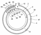
- the vaporizer 56 as a vaporization system includes a vaporization pipe 66 constituting a vaporization chamber 65 and a delivery unit 69, a first carrier gas (inert gas) 88 and a liquid raw material 63 in the vaporization chamber 65. At least a first fluid supply unit that supplies a mixed fluid mixed with the second carrier gas (inert gas) 105 to the vaporization chamber 65 toward the mixed fluid.
- a second fluid supply unit is provided once on the vaporization chamber 65, and a first fluid supply unit is provided on the other end side of the second fluid supply unit.
- the vaporizing chamber 65 includes a vaporizing tube 66, and the inner wall of the vaporizing chamber 65 is provided with tapered portions on the upper side and the lower side of the vaporizing chamber 65 so as to suppress stagnation and turbulent flow of the supplied gas.
- a discharge hole 70 is provided in the central portion of 65.
- the delivery section 69 is a portion that is vaporized to form a gas flow path.
- the plurality of discharge holes 70 correspond to the inlets, and the delivery holes 71 correspond to the outlets. Then, the gas (raw material gas) vaporized from the delivery hole 71 is supplied to the processing chamber 7.
- the first fluid supply part (A) is arranged at the upper part of the vaporization chamber 65, and the second fluid supply part (B) is arranged at the lower part of the vaporization chamber.
- Each of the first fluid supply unit and the second fluid supply unit has a gas injection hole. Therefore, the vaporizer 56 includes gas injection holes on the upper and lower opposing surfaces of the vaporization chamber 65.
- One is a mixed fluid (mist) in which the liquid raw material and the first carrier gas 88 are mixed, and the other is a second carrier gas 105 having thermal energy necessary for vaporizing the mist. And the inert gas 105 collide in the vaporizing tube 66. Needless to say, not only the vertical direction but also other different directions are possible.
- the inner wall of the vaporizing chamber 65 is provided with tapered portions 73 on the upper side and the lower side of the vaporizing chamber 65 so as to suppress stagnation and turbulent flow of the supplied gas.
- taper processing is performed from the first fluid supply unit and the second fluid supply unit to the vicinity of the discharge hole 70 to secure the flow path of the mixed fluid and the second carrier gas 105.
- the stagnation region in the vaporizing tube 66 can be reduced.
- the vaporizing tube 66 is provided with a heater (not shown), and the temperature of the wall surface is adjusted by this heater. Therefore, the heat transfer efficiency from the wall surface of the vaporizing tube 66 is improved, and the mist adhering to the wall surface is efficiently vaporized, so that the residue on the wall surface of the vaporizing tube 66 can be reduced.
- the gas (raw material gas) vaporized in the vaporizing chamber 65 is collected into one pipe by the delivery hole 71 through the plurality of discharge holes 70 and then supplied to the processing chamber 7.
- the gas flowing in from the plurality of discharge holes 70 is mixed, and the distance from the mixed portion to the delivery hole 71 is set to a predetermined length so that the direction of the flow of the mixed gas is constant.
- the discharge hole 70 provided in the side wall of the vaporization chamber 65 in this embodiment is two. However, not limited to this embodiment, three or more may be provided, and a large number are provided on the side wall of the vaporizing chamber 65 equally in the circumferential direction.
- the first fluid supply unit includes at least a nozzle holder 95 as the other end, a nozzle 96 for supplying the liquid raw material 63, and a carrier gas chamber 98.
- the nozzle holder 95 is provided with a two-fluid spray type spray nozzle 96 for atomizing the liquid raw material 63 as a spray nozzle for spraying (atomizing) the liquid raw material 63 into the vaporizing chamber 65.
- the spray nozzle 96 has a cylindrical shape, and a spray channel 97 through which the liquid raw material 63 is supplied from the gas supply pipe 45 (see FIG. 3) is formed inside the spray nozzle 96.
- an inverted frustoconical carrier gas chamber 98 having a predetermined volume is formed so as to surround the spray nozzle 96, and the spray nozzle 96 penetrates the carrier gas chamber 98 vertically. Yes.
- a carrier gas supply hole 99 is formed in the carrier gas chamber 98.
- the carrier gas supply hole 99 communicates with a gas supply pipe 85 (see FIG. 3), and a carrier gas 88 as a first carrier gas is passed from the gas supply pipe 85 to the carrier gas chamber 98 via the carrier gas supply hole 99. It comes to be supplied.
- the lower surface of the carrier gas chamber 98 is parallel to the tip of the spray nozzle 96 and is an atomizer injection port (which may be abbreviated as an injection port in some cases) as a first injection port for communicating the carrier gas chamber 98 and the vaporization chamber 65. 101) is formed.
- the injection port 101 is formed around the spray nozzle 96.
- the tip of the spray nozzle 96 protrudes slightly from the opening of the injection port 101. For example, the tip of the spray nozzle 96 protrudes from the opening of the injection port 101 by about 0.5 mm. .
- the injection port 101 is provided so as to surround the tip, and the carrier gas supplied from the injection port 101 is high speed, so the probability of surrounding adhesion is Very low.
- the tip (opening) of the spray nozzle 96 may also be included as the first jet outlet.
- the inner diameter of the ejection port 101 is extremely smaller than the inner diameter of the carrier gas supply hole 99, and the flow rate of the carrier gas 88 ejected from the ejection port 101 is the liquid material ejected from the tip of the spray channel 97. It is faster than the flow rate of 63.
- the liquid raw material 63 When the liquid raw material 63 is vaporized by the vaporizer 56, the liquid raw material 63 whose flow rate is adjusted by the LMFC 61 (see FIG. 3) is supplied from the gas supply pipe 45 to the spray passage 97, and the MFC 86 (see FIG. 3) is supplied to the carrier gas chamber 98 through the carrier gas supply hole 99.
- the inner diameter of the injection port 101 is smaller than the inner diameter of the carrier gas supply hole 99, the inside of the carrier gas chamber 98 is at a high pressure.
- the injection port 101 is 30 ⁇ m to 300 ⁇ m
- the inner diameter of the carrier gas supply hole 99 is 1.75 mm to 9.53 mm
- the ratio is preferably 50 to 300.
- the carrier gas 88 in the carrier gas chamber 98 that has become high pressure is further compressed and accelerated when passing through the injection port 101, and is ejected into the vaporization chamber 65. Further, the liquid raw material 63 supplied to the spray channel 97 is also ejected into the vaporization chamber 65 from the tip of the spray channel 97.
- the liquid raw material 63 is torn off by the high-speed carrier gas 88, whereby the liquid raw material 63 is split and atomized, and a mixed fluid in which the atomized liquid raw material 63 and the carrier gas 88 are mixed is generated. .
- the mixed fluid is sprayed into the vaporizing chamber 65 as a high-speed, high-pressure gas-liquid two-layer flow 103.
- the initial velocity at the outlet of the ejection port 101 can be increased even with a small flow rate, and by increasing the velocity, high-speed ejection can be achieved, which can contribute to droplet miniaturization.
- an improvement in vaporization efficiency can be expected, and as a result, a large flow rate of vaporized gas (raw material gas) can be expected.
- the spraying (atomization) state due to the excessive decrease in the nozzle injection speed is achieved. It does not worsen the vaporization efficiency by increasing the mist diameter. Further, if the nozzle injection speed is increased too much, the mist is scattered around the nozzle and, for example, adhering to the injection port 101 may adversely affect the nozzle injection performance. However, the injection port 101 is blocked by such mist adhesion. There is no need to consider the effects of.
- the outlet portion (tip portion) of the spray channel 97 and the outlet portion (opening portion) of the ejection port 101 are made the same height or slightly higher. If the liquid is low, the outlet portion of the spray channel 97 may be drawn into the nozzle holder 95.
- the pull-in amount is 0.5 mm to 1 mm. In this case, since the first carrier gas 88 and the liquid raw material 63 are more reliably mixed with each other, an improvement in mist efficiency is expected. As a result, improvement in vaporization efficiency is expected due to the improvement in efficiency of mist formation.
- the second fluid supply unit is provided on the opposite side of the first fluid supply unit that supplies the vaporized chamber 65 with a mixed fluid in which the first carrier gas 88 and the liquid source gas are mixed.
- the second carrier gas 105 is supplied toward the mixed fluid from the outer peripheral side toward the center side of the surface of the plate member 109 as a plate portion provided at the lower part of the vaporizing chamber 65.
- the second fluid supply unit includes a carrier gas introduction hole 106 for introducing a carrier gas 105 as a second carrier gas into the vaporizer 56 and a carrier gas introduction groove 107 that forms a flow path for the second carrier gas.
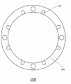
- a plate member 109 as a bottom surface portion having a plurality of holes 110 as openings that form a flow path that bypasses the second ejection holes 111, and a notch (slit) 112 communicated with the holes 110 are provided.
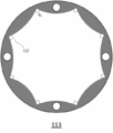
- a ring member 113 as an annular ring (slit ring) for supplying the second carrier gas 105 to the vaporizing chamber 65 through the notch 112. At least a constituting.
- the notch 112 forms a gap between the plate member 109 and the ring member 113. This gap is configured to communicate with the hole 110, and forms a flow path for the second carrier gas that has flowed through the hole 110, bypassing the second ejection hole 111.
- the second carrier gas uses a gas (Hot-N 2 gas) in which an inert gas is heated to a predetermined temperature. The presence or absence of heating is appropriately selected depending on the type of raw material.
- the plate member 109 may be referred to as a shower plate, and the ring member 113 may be referred to as a shower plate spacer. Further, the plate member 109 is provided at the lower part of the vaporizing chamber 65 (or the vaporizing tube 66) and constitutes one end of the vaporizing chamber 65 (or the vaporizing tube 66). As shown in FIG. 5, the ring member 113 is disclosed as a ring part, the plate member 109 is disclosed as a plate part, and the gas introduction member 108 is disclosed as a gas introduction part. Although not shown, each member is fixed by screwing.
- the pressure sensor 114 detects the pressure of the second fluid supply unit. The pressure sensor 114 will be described later.
- the diameter of the carrier gas introduction groove 107 provided in the gas introduction member 108 as the gas introduction portion is 2 mm as an example.
- the carrier gas introduction groove 107 is equally 8 in the circumferential direction.
- the plate member 109 has innumerable blowing holes 111 as second ejection holes formed in a circular shape (center portion) from the center of the plate member 109.
- One diameter of the blowing hole 111 is, for example, 0.1 mm.
- the plate member 109 is provided with an opening 110 at a position on the outer peripheral side of the circularly formed blowing hole 111.
- this opening part 110 is provided in the peripheral part of the plate member 109, the mixed fluid ejected from the 1st ejection port does not directly hit.
- the openings 110 are also equally provided at eight locations in the circumferential direction. As shown in FIG. 9, for example, the annular ring portion as the shower plate spacer is provided with eight notches 112 equally in the circumferential direction. The angle of the notch is 90 °. Note that the number of the notches 112 and the angle of the notches 112 can be changed as appropriate. However, the notch 112 is always configured to communicate with the hole 110.
- the second fluid supply unit supplies the second carrier gas 105 to the space formed by the gas introduction unit and the plate unit via the carrier gas introduction hole 106.
- the second carrier gas 105 supplied to this space flows upward (vertical direction) from the second ejection hole 111 provided in the plate portion, and passes through the notch portion 112 to vaporize the mixed fluid 103. It is supplied to the vaporizing chamber 65.
- the second carrier gas 105 ascends from the space formed by the gas introduction part and the plate part through the carrier gas introduction groove 107 through the opening part 110 provided in the plate part, and the taper part 73 of the vaporization tube 66.
- the direction of the flow is changed by the guide part 74 provided so as to extend in the radial direction from the lowermost part of the plate, and the liquid is supplied in the horizontal direction with respect to the surface of the plate part. That is, since the second carrier gas 105 is configured to be supplied to the center side of the plate portion through the notch portion 112 communicated with the opening portion 110, the second ejection hole 111 is clogged. In addition, the second carrier gas can be supplied to the center side of the plate portion by bypassing the second ejection holes 111.
- the opening cross-sectional area of the second ejection hole 111 is configured to be the same as or slightly smaller than the area of the lowermost portion of the tapered portion 73 provided in the vaporizing tube 66 (opening cross-sectional area of the guide portion 74 below the vaporizing tube 66). Has been.
- the fluid mixture injected from the first outlet is decomposed and scattered when it collides with the plate portion, but the heated second carrier gas 105 is supplied not only in the vertical direction on the surface of the plate member but also in the horizontal direction. Therefore, it is possible to prevent the vaporization tube 66 from adhering to the surrounding inner wall and prevent the second ejection holes on the surface of the plate member from being clogged.
- the second carrier gas 105 is configured to flow not only in the horizontal direction but also in various directions with respect to the surface of the plate portion.
- the hole (opening) 110 is in a position where the mixed fluid does not directly hit, even when the second ejection hole 111 is clogged, the supply amount of the second carrier gas 105 to the second ejection hole 111 is increased. In addition, there is an effect of suppressing the adhesion of mist even at the intended location of the hot gas blowing region on the plate surface.
- the balance between the flow rate of the mixed fluid supplied from the first ejection port and the flow rate of the second carrier gas 105 supplied from the second ejection hole 111 is optimized.
- the amount of residue adhering to the plate portion is set in a region where the ratio of the blowout amount of the first jet port and the blowout amount of the second jet hole is 1: 7 or less.
- a pressure sensor 114 is provided in a space between the gas introduction part and the plate part as a shower plate. By recording the value of the pressure sensor 114, the clogging of the second ejection hole 111 provided at the center of the plate portion is determined. Needless to say, the example shown in FIG. 5 is an example. Thus, the maintenance time of the vaporizer 56 can be determined based on the pressure value. Further, when this pressure sensor 114 is not provided, it may be possible to substitute by monitoring the gas supply pressure (the supply pressure of the second carrier gas according to the present embodiment).
- the second fluid supply unit is configured to supply the Hot-N2 gas 105 in the horizontal direction from the outer peripheral side of the plate unit toward the center side of the surface of the bottom surface of the vaporization tube 66. ing. Therefore, the mixed fluid (mist) has a high probability of mist adhesion in the region (between the holes) where the second ejection holes 111 are present in the region where the second ejection holes 111 of the shower plate are present. Even so, the Hot-N2 gas 105 can be supplied to the surface of the shower plate before the second ejection hole 111 is blocked, so that the mist adhering to the region without the second ejection hole 111 can be efficiently vaporized. Moreover, generation
- the second fluid supply unit is configured to supply the Hot-N2 gas 105 in the horizontal direction from the outer peripheral side of the plate unit toward the center side of the surface of the bottom surface of the vaporization tube 66. Therefore, in the region where the second ejection holes 111 of the shower plate are present, in the region where there is no second ejection hole 111 (between the holes), the probability of mist adhesion is high and even if mist adheres and accumulates, the second Vaporization can be performed before the ejection hole 111 is closed. Therefore, the flow rate at which the mixed fluid is ejected can be increased, and the flow rate of the vaporized gas generated at one time of the vaporizer 56 can be increased.
- the second carrier gas supplied to the surface of the shower plate from the hole 110 communicating with the gas introduction unit 108 through the notch 112 is supplied by the guide unit 74 provided in the vaporization tube 66. Since the flow path to the shower plate surface is secured, the mist adhering to the shower plate surface can be efficiently vaporized regardless of the clogging of the second ejection holes 111. Further, since the hole 110 is at a position where mist does not directly adhere, there is no concern about clogging, and improvement in the performance of the vaporizer 56 and improvement in device reliability can be expected.
- the hole 110 since the hole 110 is in a position where mist does not directly adhere, even if the second ejection hole 111 is clogged, the hole 110 is notched from the hole 110 communicating with the gas introduction unit 108.
- the second carrier gas supplied to the surface of the shower plate via the portion 112 is attached to the surface of the shower plate because a flow path to the surface of the shower plate is secured by the guide portion 74 provided in the vaporization tube 66. Mist can be vaporized.
- a gas flow path is formed in the second fluid supply part so as to bypass the second ejection hole 111, and the Hot-N2 gas 105 can be supplied to the shower plate surface in the horizontal direction.
- the second fluid supply unit can supply the second carrier gas into the vaporization chamber 65 through the flow path that bypasses the second injection hole 111, Even if clogging occurs, the fluctuation of the detection value of the pressure sensor 114 shown in FIG. 5 can be reduced, so that the number of continuous use of the vaporizer 56 can be increased. Therefore, according to the present embodiment, the device reliability is improved while maintaining the vaporization performance of the vaporizer 56.
- FIG. 12 is a graph comparing the supply pressure of the second carrier gas of the conventional vaporizer and the supply pressure of the second carrier gas 105 of the vaporizer of the present invention.
- a conventional vaporizer indicated as H12 (hereinafter referred to as a conventional product) is configured to supply the heated inert gas 105 into the vaporization chamber 65 only from the second ejection hole 111, and is indicated by H13 in the present invention.
- the vaporizer (hereinafter referred to as invention) is not only from the second ejection hole 111 but also from the carrier gas introduction groove 107 of the gas introduction part and the flow provided on the outer peripheral side from the second ejection hole 111 of the shower plate 109. It is configured to be supplied to the surface of the shower plate 109 into the vaporizing chamber 65 through the hole 110 forming the passage and the notch 112 of the shower plate spacer.
- the vaporizer 56 is inspected for both the conventional product (H12) and the invention product (H13) with a source gas flow rate of 2.0 to 4.0 g / min for 2 minutes (2.0 min). Vapor FLOW) and purge gas supply for 1 minute (1.0 min) (N2 purge) are carried out for 24 to 47 cycles.
- the inspection conditions (Test Condition) shown in FIG. 12 are that the raw material (Zr source) gas is TEMAZ gas, the raw material gas flow rate is 3.0 g / min, and 47 cycles.
- the second carrier gas 105 can be supplied through a flow path that bypasses the second ejection holes 111, so that the mist adhering to the second ejection holes 111 can be vaporized.
- any one of the following effects (a) to (j) is achieved.
- the vaporizer 56 is also mist-like droplets with respect to the liquid raw material 63 that could not be vaporized due to adiabatic expansion, so that the vaporizer 56 is vaporized in the vaporization chamber 65.
- the time is shortened, the liquid raw material 63 in the vaporizing chamber 65 reacts, or a by-product is formed, and the residue remaining in the vaporizing chamber 65 can be reduced.
- the vaporizer 56 is disposed at a position facing the first fluid supply section for supplying the mixed fluid into the vaporization chamber 65 and at a position for supplying the heated inert gas.
- the heated inert gas 105 is supplied to the mixed fluid 103 in which the liquid raw material 63 sprayed into the vaporization chamber 65 and the first carrier gas 88 are mixed.
- the vaporization efficiency is significantly improved, and the residue remaining in the vaporization chamber 65 is significantly reduced.
- the vaporizer 56 approximates the opening area of the second injection hole 111 formed in the second fluid supply unit and the cross-sectional area of the lower part of the vaporization pipe 66, and vaporizes from the lower part. Since the taper processing is performed to the vicinity of the communication port of the tube 66 and the gas flow path is secured by the plurality of communication ports, the heat transfer efficiency from the wall surface of the vaporization tube 66 is improved, and the gas flow is improved. The stagnation area decreases dramatically.
- the second fluid supply unit is heated in the vaporization chamber 65 via the plate member 109 having the second ejection holes 111 provided in the second fluid supply unit. Since the gas is sprayed and an inert gas heated horizontally is supplied to the surface of the plate member 109, not only the vaporization efficiency is remarkably improved, but also the clogging of the ejection holes of the plate is suppressed.
- the second fluid Since the flow rate of the inert gas supplied from the supply unit is set to be large, not only the vaporization efficiency is improved, but also clogging of the ejection holes of the plate is suppressed.
- the flow rate ratio between the gas flow rate supplied from the first fluid supply unit and the gas flow rate supplied from the second fluid supply unit is set to 1: 7 or less, not only the vaporization efficiency is improved, Clogging of the ejection holes of the plate is suppressed.
- the second fluid supply unit is configured to horizontally supply the inert gas heated around the ejection hole provided on the surface of the plate unit to the plate unit surface. Therefore, the vaporization efficiency by vaporizing the mixed fluid adhering to the plate portion is improved. For example, even if the mixed fluid adheres to a region where there is no ejection hole in the plate portion, it can be vaporized before clogging occurs by supplying heated inert gas to the surface of the plate portion.
- the second fluid supply unit since the second fluid supply unit has a configuration in which the gas introduction unit, the plate unit, and the ring unit are stacked, the inert gas heated around the ejection hole is platen. Can be supplied on the surface. Therefore, an increase in pressure due to clogging of the ejection holes can be suppressed, and the performance of the vaporizer 56 can be maintained over a long period of time.
- the inert gas introduced into the second fluid supply part forms a carrier gas introduction groove 107 in the gas introduction part and a flow path provided outside the ejection hole in the plate part. Since the plate portion surface is supplied in the horizontal direction into the vaporizer 56 through the hole 110 and the notch portion 112 of the ring portion, the mixed fluid supplied from the first fluid supply portion is the plate. Even if it adheres to the area
- TEMAZ is used as the liquid raw material 63, but tetrakisdiethylaminozirconium (TDEAZ, Zr [N (C2H5) 2] 4), tetrakisdimethylaminozirconium (TDMAZ, Zr [ The ZrO film may be formed using other Zr raw materials such as N (CH3) 2] 4).
- the substrate processing apparatus according to the embodiment of the present invention can be applied to film types other than ZrO as long as the film type uses a raw material having a low vapor pressure.
- a nickel film (Ni film) is formed on the wafer 6 using Ni amidinate as a gas species
- a cobalt film is formed on the wafer 6 using Co amidinate as a gas species.
- the substrate processing apparatus according to this embodiment can also be applied to the forming process.
- the first fluid gas (inert gas) 88 and the liquid source 63 mixed with the liquid source 63 are supplied to the vaporization section (the vaporization chamber 65 and the vaporization pipe 66). 1 is provided at a position facing the fluid supply part (A), and is directed from the surface of the bottom part (B. UP plate) 109 of the vaporization part (in the vaporization chamber 65 and the vaporization pipe 66) toward the mixed fluid from the surface of the second carrier.
- a second fluid supply unit (B) for supplying a gas (inert gas) 105 is supplied to the mixed fluid that has reached the bottom surface (B.
- the vaporization system configured to supply the second carrier gas 105 from the peripheral side of the bottom surface portion 109 toward the center side (parallel to the surface of the bottom surface portion or in the horizontal direction) Is provided.
- the second fluid supply unit (B) includes the hole (opening hole) 110 that forms a gas flow path on a peripheral side of the bottom surface part 109. Yes.
- the said vaporization part has the guide part 74 which changes the direction of a gas flow to the center side of the said bottom face part 109 in the downstream of the said hole (opening hole) 110. It is configured.
- the second fluid supply part (B) is provided with an enlarged part (notch part) 112 in the gap.
- the hole (opening hole) 110 is outside (outer peripheral side) than the second ejection hole (blowing hole) 111 and has a bottom surface ( B. UP plate) A large number are provided in the circumferential direction of 109.
- Appendix 7 Preferably, in the vaporization system of Appendix 1, the inside of the vaporization section is a tapered portion 73 for forming a gas flow from the second gas supply section (B) to the delivery section 69 (discharge hole 70). Is provided.
- the delivery portion 69 (discharge hole 70) is provided above the tapered portion 73.
- the second fluid supply unit (B) is configured to add a bottom surface portion on the bottom surface portion 109 of the vaporization portion from the outer peripheral side toward the center side.
- the second carrier gas 105 is supplied from 109 second ejection holes (blowing holes) 111 upward.
- the second fluid supply unit (B) is configured to supply gas that is supplied from the outer peripheral side to the central side (in the horizontal direction) on the bottom surface 109 of the vaporization unit.
- the flow rate is configured to be smaller than the flow rate of the gas supplied upward from the second ejection hole (blowing hole) 111 of the bottom surface portion 109.
- the second fluid supply unit (B) is not heated. It is configured to supply an active gas (Hot-N2 gas).
- the flow rate of the gas supplied upward from the second ejection hole (blowing hole) 111 of the bottom surface portion 109 is the second fluid supply unit.
- the flow rate of the mixed fluid (mist) supplied from the upper side of the vaporization unit is configured to be 7 times or more.
- the gasification gas having a plurality of discharge holes 70 for sending the vaporized gas to the inner wall of the vaporization pipe 66 and vaporizing the mixed fluid 70 to be sent out.
- the 1st fluid supply part (A) which supplies the mixed fluid with which the 1st carrier gas 88 and the liquid raw material 63 were mixed to the vaporization pipe 66.
- the second fluid supply part (B) for supplying the second carrier gas 105 from the bottom surface part 109 of the vaporization tube 66 toward the mixed fluid is transferred to the mixed fluid that has reached the bottom surface part 109 of the vaporization tube 66.
- a vaporization system configured to supply the second carrier gas 105 in a horizontal direction (parallel to the surface of the bottom surface portion, from the peripheral side of the bottom surface portion to the center side) is provided.
- the second fluid supply unit (B) is a hole (opening hole) that forms a flow path through which the second carrier gas 105 flows in a peripheral portion of the bottom surface portion 109. ) 110 is configured.
- the vaporizing pipe 66 is configured to be provided with a discharge hole 70 for sending a vaporized gas obtained by vaporizing the mixed fluid.
- the vaporization pipe 66 is configured such that a flow path through which the vaporized gas obtained by vaporizing the mixed fluid flows into the discharge hole is formed.
- the second carrier gas 105 is a heated inert gas.
- the second fluid supply unit (B) allows gas to flow upward from the second ejection holes 111 of the bottom surface portion 109. Configured to supply.
- a processing chamber for accommodating a substrate, a reactive gas supply system for supplying a reactive gas to the substrate, and a vaporized gas obtained by vaporizing a liquid raw material with a vaporizer
- a source gas supply system that supplies the processing chamber; and a control unit that controls at least the reaction gas supply system and the source gas supply system.
- the vaporizer includes a first carrier gas and a liquid source therein.
- a first fluid supply unit configured to supply a mixed fluid mixture, and a second fluid supply unit configured to supply a second carrier gas from the surface of the bottom surface of the vaporization tube toward the mixed fluid (in a vertical direction).
- the second fluid supply unit is configured to supply the second carrier gas from the outer peripheral side of the bottom surface part to the center side toward the mixed fluid that has reached the bottom surface part of the vaporization tube.
- a processing device is provided.
- a process of supplying a vaporized gas obtained by vaporizing a liquid raw material with a vaporizer to a processing chamber containing a substrate as a raw material gas, and supplying the raw material gas from the processing chamber A step of removing, a step of supplying a reactive gas to the processing chamber from which the raw material gas has been removed, a step of removing the reactive gas from the processing chamber, and a step of supplying the raw material gas to the processing chamber, A mixed fluid in which a first carrier gas and a liquid raw material are mixed is supplied into the vaporizer, and a second carrier gas is supplied toward the mixed fluid from the surface of the bottom surface of the vaporizer tube (in the vertical direction). Supplying the second carrier gas from the peripheral side of the bottom surface to the center toward the mixed fluid that has reached the bottom surface of the vaporization tube.
- a procedure of supplying a vaporized gas obtained by vaporizing a liquid raw material with a vaporizer to a processing chamber containing a substrate as a raw material gas in a computer, and a raw material from the processing chamber A program for executing a procedure for removing a gas, a procedure for supplying a reaction gas to the processing chamber from which the source gas has been removed, and a procedure for removing the reaction gas from the processing chamber, and a computer-readable record of the program
- the procedure of supplying a raw material gas to the processing chamber is a medium, wherein a mixed fluid in which a first carrier gas and a liquid raw material are mixed is supplied into the vaporizer, and the bottom surface of the vaporization tube is directed toward the mixed fluid.
- the second carrier gas is supplied from the surface of the bottom part (in the vertical direction), and the second key is moved from the peripheral side of the bottom part to the center side toward the mixed fluid that has reached the bottom part of the vaporization pipe.
- Program at least with a procedure for supplying Riagasu, and computer readable recording medium for the program is provided.
- a processing chamber for accommodating a substrate, a reactive gas supply system for supplying a reactive gas to the substrate, and a vaporized gas obtained by vaporizing a liquid raw material with a vaporizer
- a source gas supply system that supplies the process chamber; and a control unit that controls at least the reaction gas supply system and the source gas supply system.
- the vaporizer includes a first carrier gas and a liquid source gas. A first fluid supply section for supplying the mixed gas, and a second carrier provided in a position facing the first fluid supply section from the surface of the bottom portion of the vaporization tube toward the mixed fluid (in the vertical direction).
- a second fluid supply part for supplying gas and the second fluid supply part is directed from the peripheral side to the center side of the bottom part toward the mixed fluid that has reached the bottom part of the vaporization pipe (in the horizontal direction).
- a substrate processing apparatus configured as described above is provided.
- a step of supplying a vaporized gas obtained by vaporizing a liquid raw material with a vaporizer to a processing chamber containing a substrate as a raw material gas, and supplying the raw material gas from the processing chamber A step of removing, a step of supplying a reactive gas to the processing chamber from which the raw material gas has been removed, a step of removing the reactive gas from the processing chamber, and a step of supplying the raw material gas to the processing chamber, A mixed fluid of a first carrier gas and a liquid raw material is supplied into the vaporizer, a second carrier gas is supplied from the surface of the bottom surface of the vaporization tube toward the mixed gas (in the vertical direction), and the vaporization tube And supplying the second carrier gas from the peripheral side of the bottom surface portion toward the center side (in the horizontal direction) toward the mixed fluid that has reached the bottom surface portion of the semiconductor device.
- a procedure for supplying a vaporized gas obtained by vaporizing a liquid raw material with a vaporizer to a computer as a raw material gas into a processing chamber in which a substrate is stored, and a raw material from the processing chamber A program for executing a procedure for removing a gas, a procedure for supplying a reaction gas to the processing chamber from which the source gas has been removed, and a procedure for removing the reaction gas from the processing chamber, and a computer-readable record of the program
- the procedure of supplying a raw material gas to the processing chamber is a medium, wherein a mixed fluid in which a first carrier gas and a liquid raw material are mixed is supplied into the vaporizer, and the bottom surface of the vaporization tube is directed toward the mixed fluid.
- the second carrier gas is supplied from the surface of the part (in the vertical direction) and the second carrier gas is supplied in the horizontal direction toward the mixed gas that has reached the bottom part of the vaporization tube.
- Program having at least a preparative, and computer readable recording medium the program is provided.
- the vaporization chamber 65 having one end 109 and the other end 95 is connected to the vaporization chamber 65 at the other end 95, and directed toward the one end 109.
- the second fluid supply unit (B) has a hole forming a flow path through which the second carrier gas 105 flows on the peripheral side of the one end 109. 110 is formed.
- the second fluid supply unit (B) has a flow of the second carrier gas 105 supplied from the hole downstream of the hole 110.
- a guide portion 74 that changes the direction to the center side of the one end portion 109 is configured.
- the second fluid supply unit (B) is configured such that a gap is provided between the guide unit 74 and the hole 110.
- a plurality of cutout portions 112 for communicating the vaporizing chamber 65 and the hole 110 are provided in the peripheral portion of the one end portion.
- a site is constructed.
- the second fluid supply unit (B) includes a space connected to the hole 110 on the upstream side of the hole 110, and the second fluid supply unit (B).
- a gas introduction unit 108 for introducing the two carrier gas 105 is configured.
- a portion on a peripheral side of the one end portion is provided in the space so that a plurality of groove portions 107 for communicating the hole 110 and the gas introduction portion 108 are provided. Is configured.
- the second fluid supply unit (B) is formed with an ejection hole 111 for ejecting the second carrier gas 105 on the center side of the bottom surface portion 109. Configured to
- the second fluid supply unit (B) is configured such that the second fluid supply part (B) is directed from the ejection hole 111 of the bottom surface part 109 toward the mixed fluid on the center side of the one end part.
- the second carrier gas 105 is configured to be supplied.
- the vaporization system is any one of Supplementary note 28 to Supplementary note 30, Supplementary note 33, Supplementary note 35, or Supplementary note 36, and the second carrier gas 105 is a heated inert gas. .
- the opening cross-sectional area of the guide portion 74 of the vaporization tube 66 and the area of the ejection hole 111 formed on the center side of the one end portion 109 are substantially the same. Is done.
- the side wall of the vaporization pipe 66 is a discharge for discharging the gas, which is obtained by vaporizing the mixed fluid by the second carrier gas 105, from the vaporization chamber 65.
- a hole 70 is configured to be provided.
- the discharge holes 70 are configured to be provided in a large number equally in the circumferential direction on the side wall of the vaporization tube 66.
- the vaporization chamber 65 has a flow path for the vaporized gas formed in the vaporization chamber 65, and the vaporized gas is It is configured to flow into the discharge hole 70.
- a processing chamber for containing a substrate, a reaction gas supply system for supplying a reaction gas to the substrate, and a vaporized gas obtained by vaporizing a liquid raw material with a vaporizer is a raw material gas.
- a raw material gas supply system for supplying to the processing chamber as the vaporizer, the vaporizer having one end and the other end, connected to the vaporization chamber at the other end, the one end
- a first fluid supply part for supplying a first carrier gas and a mixed fluid in which a liquid material is mixed toward the first part, and a second carrier from the peripheral side of the one end part toward the center side toward the mixed fluid at the one end part
- a substrate processing apparatus including a second fluid supply unit that supplies a gas.
- a vaporization chamber having one end and another end, and connected to the vaporization chamber at the other end, and a first carrier gas toward the one end
- a first fluid supply section for supplying a mixed fluid mixed with a liquid raw material; and a second fluid supply for supplying a second carrier gas from the peripheral side of the one end to the center toward the mixed fluid at the one end.
- a method for manufacturing a semiconductor device which includes a step of supplying a reactive gas to the removed processing chamber and a step of removing the reactive gas from the processing chamber.
- a mixed fluid in which the first carrier gas and the liquid raw material are mixed is supplied from the other end toward the one end, and toward the mixed fluid at the one end.
- a step of supplying a second carrier gas from the peripheral side of the one end portion to the center side to vaporize the mixed fluid, a step of supplying the vaporized gas as a raw material gas to a processing chamber containing a substrate, and the processing chamber There is provided a method for manufacturing a semiconductor device, comprising: a step of removing a source gas from the substrate; a step of supplying a reaction gas to the processing chamber from which the source gas has been removed; and a step of removing the reaction gas from the processing chamber.
- a mixed fluid in which the first carrier gas and the liquid raw material are mixed is supplied from the other end toward the one end, and toward the mixed fluid at the one end.
- a method is provided in which a second carrier gas is supplied from the peripheral side of the one end to the center side to vaporize the mixed fluid.
- the computer is connected to the vaporization chamber having one end and the other end, and the vaporization chamber is connected to the first end toward the one end.
- a first fluid supply section for supplying a carrier gas and a mixed fluid in which a liquid material is mixed; and a second carrier gas for supplying a second carrier gas from the peripheral edge side to the center side of the one end section toward the mixed fluid at the one end section.
- a procedure for supplying a vaporized gas obtained by vaporizing a liquid source by a vaporizer comprising a two-fluid supply unit to a processing chamber in which a substrate is accommodated as a source gas, a procedure for removing the source gas from the processing chamber, and a source gas
- a program for executing a procedure for supplying a reactive gas to the processing chamber from which the gas is removed, a procedure for removing the reactive gas from the processing chamber, and a computer-readable recording medium are provided.
- the present invention relates to a technique for supplying a vaporized gas obtained by vaporizing a liquid material, and in particular, can be applied to a substrate processing apparatus that performs a predetermined process on a substrate using the vaporized gas obtained by vaporizing a liquid material.
Landscapes
- Chemical & Material Sciences (AREA)
- Engineering & Computer Science (AREA)
- Chemical Kinetics & Catalysis (AREA)
- Organic Chemistry (AREA)
- General Chemical & Material Sciences (AREA)
- Materials Engineering (AREA)
- Mechanical Engineering (AREA)
- Metallurgy (AREA)
- Physics & Mathematics (AREA)
- Condensed Matter Physics & Semiconductors (AREA)
- General Physics & Mathematics (AREA)
- Manufacturing & Machinery (AREA)
- Computer Hardware Design (AREA)
- Microelectronics & Electronic Packaging (AREA)
- Power Engineering (AREA)
- Inorganic Chemistry (AREA)
- Dispersion Chemistry (AREA)
- Chemical Vapour Deposition (AREA)
- Feeding, Discharge, Calcimining, Fusing, And Gas-Generation Devices (AREA)
Abstract
In order to provide a configuration that reduces the residue within a vaporizer while significantly enhancing vaporization performance, provided is a configuration that is equipped with: a vaporization chamber that has one end section and another end section; a first liquid supplying section that is connected to the vaporization chamber at the other end section and supplies, toward the one end section, a mixed liquid containing a first carrier gas mixed with a liquid starting material; and a second liquid supplying section that supplies, toward the mixed liquid at the one end section, a second carrier gas from the peripheral edge sides of the one end section toward the center thereof.
Description
本発明は、基板処理装置、半導体装置の製造方法及び気化システムに関する。
The present invention relates to a substrate processing apparatus, a semiconductor device manufacturing method, and a vaporization system.
基板を処理する処理装置として、処理炉を有し、該処理炉内に画成された所定枚数の基板を収納し、基板を所定温度に加熱し、処理ガスを処理室内に供給して基板処理を行う基板処理装置がある。
As a processing apparatus for processing a substrate, it has a processing furnace, stores a predetermined number of substrates defined in the processing furnace, heats the substrate to a predetermined temperature, and supplies a processing gas into the processing chamber to process the substrate. There is a substrate processing apparatus for performing the above.
上記した基板処理装置には、処理ガスの原料として液体原料を用いるものがあり、液体原料を気化器が微粒化させた後気化させることで気化ガス(原料ガス)を生成し、生成した気化ガスを処理ガスとして処理室内に供給している。
Some of the substrate processing apparatuses described above use a liquid raw material as a raw material for the processing gas, and generate a vaporized gas (raw material gas) by vaporizing the liquid raw material after the vaporizer is atomized, and the generated vaporized gas Is supplied into the processing chamber as a processing gas.
従来では、バブリング方式、ベーキング方式、直接気化方式等により液体原料を気化させる気化器があるが、特に、気化器内が減圧された減圧場(高真空場)に於いては液体原料の気化を促進するのが困難であった。特許文献1によれば、液体原料を微粒化し、輻射熱等により気化させる気化方式が開示されている。それでも、上部から高速噴射された気液混合物が気化器の内壁まで到達し、気化器内に残留して残渣が生じる場合がある。従い、不活性ガスによるキャリアガスをこの気液混合物に供給して気化を促進させる等、気化器内での気化効率を向上し、気化器内に残留する残渣を抑制することが行われている。
Conventionally, there are vaporizers that vaporize liquid raw materials by bubbling method, baking method, direct vaporization method, etc., but especially in the reduced pressure field (high vacuum field) where the inside of the vaporizer is depressurized, the liquid raw material is vaporized. It was difficult to promote. According to Patent Document 1, a vaporization method is disclosed in which a liquid raw material is atomized and vaporized by radiant heat or the like. Nevertheless, the gas-liquid mixture sprayed at a high speed from the upper part may reach the inner wall of the vaporizer and remain in the vaporizer to form a residue. Therefore, it is carried out to improve the vaporization efficiency in the vaporizer and to suppress the residue remaining in the vaporizer, for example, by promoting the vaporization by supplying a carrier gas by an inert gas to the gas-liquid mixture. .
しかしながら、気化方式は、キャリアガスの有無、気化器側の圧力範囲、原料特性等、各種条件とのマッチングにより選択されるものであり、気化効率が良く、且つ、残渣も低減できる万能な気化器は、現在まで開発できていない。
However, the vaporization method is selected by matching with various conditions such as presence / absence of carrier gas, pressure range on the vaporizer side, raw material characteristics, etc., and it is a versatile vaporizer that has good vaporization efficiency and can reduce residue. Has not been developed to date.
本発明は、気化器内の残渣を低減しつつ、気化性能を著しく向上させた構成を提供するものである。
The present invention provides a configuration in which the vaporization performance is remarkably improved while reducing the residue in the vaporizer.
本発明の一態様によれば、一端部と他端部とを有する気化室と、前記他端部で気化室に接続され、前記一端部に向けて第1キャリアガスと液体原料が混合された混合流体とを供給する第1流体供給部と、前記一端部の前記混合流体に向けて前記一端部の周縁側から中心側へ第2キャリアガスを供給する第2流体供給部と、を備える構成が提供される。
According to one aspect of the present invention, the vaporization chamber having one end and the other end is connected to the vaporization chamber at the other end, and the first carrier gas and the liquid material are mixed toward the one end. A first fluid supply section for supplying a mixed fluid; and a second fluid supply section for supplying a second carrier gas from the peripheral side of the one end to the center toward the mixed fluid at the one end. Is provided.
本発明によれば、気化器内の残渣を低減しつつ、気化性能を著しく向上させることができるという優れた効果を発揮する。
According to the present invention, an excellent effect that the vaporization performance can be remarkably improved while reducing the residue in the vaporizer is exhibited.
以下、図面を参照しつつ本発明の実施例を説明する。
Hereinafter, embodiments of the present invention will be described with reference to the drawings.
先ず、半導体装置の製造工程の一工程で使用される半導体製造装置の一例である、基板処理装置について説明する。尚、以下では、該基板処理装置の一例として、一度に複数枚の基板に対して成膜処理等を行うバッチ式の縦型装置である基板処理装置を使用した場合について説明する。
First, a substrate processing apparatus, which is an example of a semiconductor manufacturing apparatus used in one process of a semiconductor device manufacturing process, will be described. Hereinafter, as an example of the substrate processing apparatus, a case will be described in which a substrate processing apparatus that is a batch type vertical apparatus that performs film formation processing or the like on a plurality of substrates at once will be described.
図1及び図2を用いて、本実施形態における基板処理装置の処理炉1について説明する。
The processing furnace 1 of the substrate processing apparatus in the present embodiment will be described with reference to FIGS.
処理炉1は、中心線が垂直になる様に縦向きに配置され、筐体(図示せず)により固定的に支持された反応管としての縦型のプロセスチューブ2を有している。プロセスチューブ2は、インナチューブ3とアウタチューブ4とを有している。インナチューブ3及びアウタチューブ4は、例えば石英(SiO2)又は炭化珪素(SiC)、石英や炭化珪素の複合材料等耐熱性の高い材料によって、それぞれ一体に成形されている。
The processing furnace 1 has a vertical process tube 2 as a reaction tube that is vertically arranged so that the center line is vertical and is fixedly supported by a casing (not shown). The process tube 2 has an inner tube 3 and an outer tube 4. The inner tube 3 and the outer tube 4 are each integrally formed of a material having high heat resistance such as quartz (SiO 2) or silicon carbide (SiC), a composite material of quartz or silicon carbide.
インナチューブ3は、上端が閉塞され下端が開放された円筒形状であり、インナチューブ3内には基板保持手段(基板保持具)としてのボート5が収納され、該ボート5にはウェーハ6が水平姿勢で多段に積層されており、インナチューブ3にウェーハ6を収納して処理する処理室7が画成される。インナチューブ3の下端開口は、ウェーハ6を保持したボート5を挿脱する為の炉口を構成している。従って、インナチューブ3の内径は、ウェーハ6を保持したボート5の最大外径よりも大きくなる様に設定されている。
The inner tube 3 has a cylindrical shape with the upper end closed and the lower end opened, and a boat 5 serving as a substrate holding means (substrate holder) is accommodated in the inner tube 3, and a wafer 6 is horizontally placed in the boat 5. A plurality of layers are stacked in a posture, and a processing chamber 7 in which the wafer 6 is accommodated and processed in the inner tube 3 is defined. The lower end opening of the inner tube 3 constitutes a furnace port for inserting and removing the boat 5 holding the wafer 6. Therefore, the inner diameter of the inner tube 3 is set to be larger than the maximum outer diameter of the boat 5 holding the wafer 6.
アウタチューブ4は、上端が閉塞され下端が開口された円筒形状であり、内径がインナチューブ3よりも大きく、該インナチューブ3の外側を囲む様同心に配置される。アウタチューブ4の下端部は、マニホールド8のフランジ9にOリング(図示せず)を介して取付けられ、Oリングにより気密に封止される。
The outer tube 4 has a cylindrical shape with the upper end closed and the lower end opened, and has an inner diameter larger than that of the inner tube 3 and is concentrically arranged so as to surround the outer side of the inner tube 3. The lower end portion of the outer tube 4 is attached to the flange 9 of the manifold 8 via an O-ring (not shown), and is hermetically sealed by the O-ring.
インナチューブ3の下端部は、マニホールド8の内周面に形成された円板状のリング部11上に載置されている。マニホールド8には、インナチューブ3及びアウタチューブ4についての保守点検作業や清掃作業の為、インナチューブ3及びアウタチューブ4が着脱自在に取付けられている。更に、マニホールド8が筐体(図示せず)に支持されることにより、プロセスチューブ2は垂直に据付けられた状態になっている。
The lower end portion of the inner tube 3 is placed on a disk-shaped ring portion 11 formed on the inner peripheral surface of the manifold 8. The inner tube 3 and the outer tube 4 are detachably attached to the manifold 8 for maintenance and inspection work and cleaning work on the inner tube 3 and the outer tube 4. Further, the process tube 2 is vertically installed by supporting the manifold 8 in a housing (not shown).
尚、上記に於いてはインナチューブ3の内部に画成される空間を処理室7としているが、以下では、アウタチューブ4内に画成される空間を処理室7と呼ぶ場合もある。
In the above description, the space defined inside the inner tube 3 is referred to as the processing chamber 7, but hereinafter, the space defined in the outer tube 4 may be referred to as the processing chamber 7.
マニホールド8の側壁の一部には、処理室7内の雰囲気を排気する排気管12が接続されている。マニホールド8と排気管12との接続部には、処理室7内の雰囲気を排気する排気口が形成されている。排気管12内は、排気口を介してインナチューブ3とアウタチューブ4との間に形成された排気路47(後述)内に連通している。尚、該排気路47の横断面形状は略円形リング状になっている。これにより、後述するインナチューブ3に形成された排気孔13の上端から下端迄均一に排気することができる。即ち、ボート5に載置された複数枚のウェーハ6全てから均一に排気することができる。
An exhaust pipe 12 that exhausts the atmosphere in the processing chamber 7 is connected to a part of the side wall of the manifold 8. An exhaust port for exhausting the atmosphere in the processing chamber 7 is formed at a connection portion between the manifold 8 and the exhaust pipe 12. The inside of the exhaust pipe 12 communicates with an exhaust path 47 (described later) formed between the inner tube 3 and the outer tube 4 through an exhaust port. Note that the cross-sectional shape of the exhaust passage 47 is a substantially circular ring shape. Thereby, it can exhaust uniformly from the upper end of the exhaust hole 13 formed in the inner tube 3 mentioned later to a lower end. That is, it is possible to uniformly exhaust air from all the plurality of wafers 6 placed on the boat 5.
排気管12には、上流側から順に、圧力センサ14、圧力調整器としてのAPC(Auto Pressure Controller)バルブ15、真空排気装置としての真空ポンプ16が設けられている。該真空ポンプ16は、処理室7内の圧力が所定の圧力(真空度)となる様真空排気し得る様に構成されている。圧力センサ14及びAPCバルブ15には、コントローラ17が電気的に接続されている。該コントローラ17は、処理室7内の圧力が所望のタイミングにて所望の圧力となる様に、圧力センサ14により検出された圧力に基づいてAPCバルブ15の開度を制御する様に構成されている。
The exhaust pipe 12 is provided with a pressure sensor 14, an APC (Auto Pressure Controller) valve 15 as a pressure regulator, and a vacuum pump 16 as a vacuum exhaust device in order from the upstream side. The vacuum pump 16 is configured to be evacuated so that the pressure in the processing chamber 7 becomes a predetermined pressure (degree of vacuum). A controller 17 is electrically connected to the pressure sensor 14 and the APC valve 15. The controller 17 is configured to control the opening degree of the APC valve 15 based on the pressure detected by the pressure sensor 14 so that the pressure in the processing chamber 7 becomes a desired pressure at a desired timing. Yes.
主に、排気管12、圧力センサ14、APCバルブ15により、本実施例に係る排気ユニット(排気系)が構成される。又、該排気ユニットには真空ポンプ16を含めてもよい。又、排気管12には、排気ガス中の反応副生成物や未反応の原料ガス等を補足するトラップ装置や、排気ガス中に含まれる腐食成分や有毒成分等を除外する除外装置が接続されている場合がある。この場合、トラップ装置や除外装置を排気ユニットに含めてもよい。
Mainly, the exhaust pipe 12, the pressure sensor 14, and the APC valve 15 constitute an exhaust unit (exhaust system) according to the present embodiment. The exhaust unit may include a vacuum pump 16. The exhaust pipe 12 is connected to a trap device that supplements reaction by-products and unreacted source gas in the exhaust gas, and an exclusion device that excludes corrosive components and toxic components contained in the exhaust gas. There may be. In this case, a trap device or an exclusion device may be included in the exhaust unit.
マニホールド8には、該マニホールド8の下端開口を閉塞するシールキャップ18が垂直下方から当接される。該シールキャップ18は、アウタチューブ4の外径と同等以上の外径を有する円盤形状となっており、プロセスチューブ2の外部に垂直に設置されたボートエレベータ19によって水平姿勢で垂直方向に昇降される。
A seal cap 18 that closes the lower end opening of the manifold 8 is brought into contact with the manifold 8 from vertically below. The seal cap 18 has a disk shape having an outer diameter equal to or larger than the outer diameter of the outer tube 4, and is lifted and lowered in a vertical position in a horizontal posture by a boat elevator 19 installed vertically outside the process tube 2. The
シールキャップ18上には、ウェーハ6を保持するボート5が垂直に立脚されて支持されている。該ボート5は、上下で一対の端板21と、該端板21間に垂直に設けられた複数本の保持部材22とを有している。端板21及び保持部材22は、例えば石英又はSiC、石英や炭化珪素の複合材料等の耐熱性材料からなる。各保持部材22には、多数条の保持溝23が長手方向に等間隔に形成されている。ウェーハ6の円周縁が複数本の保持部材22に於ける同一段の保持溝23内にそれぞれ挿入されることにより、複数枚のウェーハ6が水平姿勢且つ互いに中心を揃えた状態で多段に積層されて保持される。
On the seal cap 18, the boat 5 holding the wafer 6 is vertically supported and supported. The boat 5 includes a pair of upper and lower end plates 21 and a plurality of holding members 22 provided vertically between the end plates 21. The end plate 21 and the holding member 22 are made of a heat resistant material such as quartz or SiC, a composite material of quartz or silicon carbide, for example. Each holding member 22 has a plurality of holding grooves 23 formed at equal intervals in the longitudinal direction. By inserting the circumferential edges of the wafers 6 into the holding grooves 23 on the same stage in the plurality of holding members 22, the plurality of wafers 6 are stacked in multiple stages in a horizontal posture and aligned with each other in the center. Held.
ボート5とシールキャップ18との間には、上下で一対の補助端板24が複数本の補助保持部材25によって支持されている。各補助保持部材25には、多数条の保持溝26が形成されている。該保持溝26には、例えば石英やSiC等の耐熱性材料からなる円板形状の複数枚の断熱板27が、水平姿勢で多段に装填される。該断熱板27によって、後述するヒータユニット28からの熱が前記マニホールド8側に伝わり難くなっている。又、ボート5に載置される複数枚のウェーハ6の下側での温度低下を抑制できる様になっている。
Between the boat 5 and the seal cap 18, a pair of auxiliary end plates 24 are supported by a plurality of auxiliary holding members 25 in the vertical direction. Each auxiliary holding member 25 has a plurality of holding grooves 26 formed therein. A plurality of disk-shaped heat insulating plates 27 made of a heat-resistant material such as quartz or SiC are loaded in the holding groove 26 in multiple stages in a horizontal posture. The heat insulating plate 27 makes it difficult for heat from a heater unit 28 described later to be transferred to the manifold 8 side. Further, a temperature drop on the lower side of the plurality of wafers 6 placed on the boat 5 can be suppressed.
シールキャップ18の処理室7と反対側には、ボート5を回転させる回転機構29が設けられている。該回転機構29の回転軸31は、シールキャップ18を貫通してボート5を下方から支持している。回転機構29により回転軸31を回転させることで、処理室7内にてウェーハ6を回転させることができる。
A rotation mechanism 29 for rotating the boat 5 is provided on the opposite side of the seal cap 18 from the processing chamber 7. A rotating shaft 31 of the rotating mechanism 29 passes through the seal cap 18 and supports the boat 5 from below. By rotating the rotation shaft 31 by the rotation mechanism 29, the wafer 6 can be rotated in the processing chamber 7.
又、シールキャップ18は、搬送手段(搬送機構)としてのボートエレベータ19によって垂直方向に昇降される様に構成されており、該ボートエレベータ19によってボート5を処理室7内外に搬送することが可能となっている。
Further, the seal cap 18 is configured to be moved up and down in the vertical direction by a boat elevator 19 as a transport means (transport mechanism), and the boat 5 can be transported into and out of the processing chamber 7 by the boat elevator 19. It has become.
アウタチューブ4の外部には、プロセスチューブ2内を全体に亘って均一又は所定の温度分布に加熱する加熱手段(加熱機構)としてのヒータユニット28が、アウタチューブ4を囲繞する様に設けられている。ヒータユニット28は、基板処理装置の筐体(図示せず)に支持されることにより、垂直に据付けられた状態となっており、例えばカーボンヒータ等の抵抗加熱ヒータとして構成されている。
Outside the outer tube 4, a heater unit 28 is provided as a heating means (heating mechanism) for heating the inside of the process tube 2 uniformly or with a predetermined temperature distribution so as to surround the outer tube 4. Yes. The heater unit 28 is vertically installed by being supported by a housing (not shown) of the substrate processing apparatus, and is configured as a resistance heater such as a carbon heater.
プロセスチューブ2内には、温度検出器としての温度センサ32が設置されている。主に、ヒータユニット28、温度センサ32により、本実施例に係る加熱ユニット(加熱系)が構成される。
In the process tube 2, a temperature sensor 32 as a temperature detector is installed. The heating unit (heating system) according to this embodiment is mainly configured by the heater unit 28 and the temperature sensor 32.
インナチューブ3の側壁(後述する排気孔13とは180°反対側の位置)には、チャンネル形状の予備室33が、インナチューブ3の側壁から該インナチューブ3の径方向外向きに突出して垂直方向に長く延在する様に形成されている。又、予備室33の内壁は処理室7の内壁の一部を形成している。
On the side wall of the inner tube 3 (a position on the opposite side to the exhaust hole 13 to be described later), a channel-shaped auxiliary chamber 33 projects vertically outward from the inner tube 3 in the radial direction of the inner tube 3. It is formed so as to extend long in the direction. Further, the inner wall of the preliminary chamber 33 forms a part of the inner wall of the processing chamber 7.
予備室33の内部には、該予備室33の内壁(即ち処理室7の内壁)に沿う様に、予備室33の下部から上部に沿ってウェーハ6の積層方向に延在し、処理室7内にガスを供給するノズル34,35,36,37が設けられている。即ち、該ノズル34,35,36,37は、ウェーハ6が配列されるウェーハ配列領域の側方の、ウェーハ配列領域を水平に取囲む領域に、ウェーハ配列領域に沿う様に設けられている。
The spare chamber 33 extends in the stacking direction of the wafers 6 along the inner wall of the spare chamber 33 (that is, the inner wall of the processing chamber 7) from the lower portion to the upper portion of the spare chamber 33. Nozzles 34, 35, 36 and 37 for supplying gas are provided therein. That is, the nozzles 34, 35, 36, and 37 are provided on the side of the wafer arrangement region where the wafers 6 are arranged, in a region that horizontally surrounds the wafer arrangement region, along the wafer arrangement region.
ノズル34,35,36,37は、L字型のロングノズルとして構成されており、該ノズル34,35,36,37の水平部はマニホールド8を貫通し、ノズル34,35,36,37の垂直部はウェーハ配列領域の下端から上端に向って立ち上がる様に設けられている。尚、便宜上、図1には1本のノズル34を記載しているが、実際には図2に示される様に、4本のノズル34,35,36,37が設けられている。
The nozzles 34, 35, 36, and 37 are configured as L-shaped long nozzles, and the horizontal portions of the nozzles 34, 35, 36, and 37 pass through the manifold 8, and the nozzles 34, 35, 36, and 37 The vertical portion is provided so as to rise from the lower end to the upper end of the wafer arrangement region. For convenience, one nozzle 34 is shown in FIG. 1, but actually four nozzles 34, 35, 36, and 37 are provided as shown in FIG.
又、該ノズル34,35,36,37の側面には、ガスを供給する多数のガス供給孔38,39,40,41がそれぞれ設けられている。該ガス供給孔38,39,40,41は、下部から上部に亘ってそれぞれ同一、又は大きさに傾斜を付けた開口面積を有し、更に同一の開口ピッチで設けられている。
Further, a large number of gas supply holes 38, 39, 40, 41 for supplying gas are provided on the side surfaces of the nozzles 34, 35, 36, 37, respectively. The gas supply holes 38, 39, 40, 41 have the same or inclined opening areas from the bottom to the top, and are provided at the same opening pitch.
マニホールド8を貫通したノズル34,35,36,37の水平部の端部は、プロセスチューブ2の外部で、ガス供給ラインとしてのガス供給管43,44,45,46とそれぞれ接続されている。
The horizontal ends of the nozzles 34, 35, 36 and 37 penetrating the manifold 8 are connected to gas supply pipes 43, 44, 45 and 46 as gas supply lines outside the process tube 2, respectively.
上記した様に、本実施例に於けるガス供給の方法は、予備室33内に配置されたノズル34,35,36,37を介してガスを搬送し、ガス供給孔38,39,40,41からウェーハ6の近傍より処理室7内にガスを噴出させている。
As described above, the gas supply method in the present embodiment is such that the gas is conveyed through the nozzles 34, 35, 36, 37 disposed in the auxiliary chamber 33, and the gas supply holes 38, 39, 40, A gas is blown into the processing chamber 7 from the vicinity of the wafer 6 from 41.
インナチューブ3の側壁であって、ノズル34,35,36,37に対向した位置、即ち予備室33とは180°反対側の位置には、例えばスリット状の貫通孔である排気孔13が垂直方向に細長く開設されている。インナチューブ3とアウタチューブ4との間に排気路47が形成され、該排気路47は排気孔13を介して処理室7と連通している。従って、ガス供給孔38,39,40,41から処理室7内に供給されたガスは、排気孔13を介して排気路47内へと流れた後、排気口を介して排気管12内に流れ、処理室7外へと排出される。
On the side wall of the inner tube 3 and facing the nozzles 34, 35, 36, 37, that is, at a position opposite to the spare chamber 33 by 180 °, the exhaust hole 13, for example, a slit-shaped through hole is vertical. Opened in the direction elongated. An exhaust path 47 is formed between the inner tube 3 and the outer tube 4, and the exhaust path 47 communicates with the processing chamber 7 through the exhaust hole 13. Therefore, the gas supplied into the processing chamber 7 from the gas supply holes 38, 39, 40, 41 flows into the exhaust passage 47 through the exhaust hole 13, and then enters the exhaust pipe 12 through the exhaust port. The flow is discharged out of the processing chamber 7.
この時、ガス供給孔38,39,40,41から処理室7内のウェーハ6の近傍に供給されたガスは、水平方向、即ちウェーハ6の表面と平行な方向に向って流れた後、排気孔13を介して排気路47へと流れる。つまり、処理室7内に於けるガスの主たる流れは水平方向、即ちウェーハ6の表面と平行な方向となる。この様な構成とすることで、各ウェーハ6に対して均一にガスを供給でき、各ウェーハ6に形成される薄膜の膜厚を均一にすることができる。尚、排気孔13はスリット状の貫通孔に限らず、複数個の孔により形成されていてもよい。
At this time, the gas supplied from the gas supply holes 38, 39, 40, 41 to the vicinity of the wafer 6 in the processing chamber 7 flows in the horizontal direction, that is, in the direction parallel to the surface of the wafer 6, and then exhausted. It flows to the exhaust passage 47 through the hole 13. That is, the main flow of gas in the processing chamber 7 is in the horizontal direction, that is, the direction parallel to the surface of the wafer 6. With such a configuration, gas can be supplied uniformly to each wafer 6, and the film thickness of the thin film formed on each wafer 6 can be made uniform. The exhaust hole 13 is not limited to a slit-like through hole, and may be formed by a plurality of holes.
次に、図3を参照して本実施例に係るガス供給系について説明する。
Next, the gas supply system according to this embodiment will be described with reference to FIG.
ガス供給管43には、上流側から順に、流量制御装置(流量制御部)としてのMFC(マスフローコントローラ)48及び開閉弁であるバルブ49がそれぞれ設けられており、例えば不活性ガスである窒素(N2)ガスがガス供給管43及びノズル34を通って処理室7へ供給される。主に、ノズル34、ガス供給管43、MFC48、バルブ49により第1の不活性ガス供給系が構成される。
The gas supply pipe 43 is provided with an MFC (mass flow controller) 48 as a flow rate control device (flow rate control unit) and a valve 49 as an on-off valve in order from the upstream side. For example, nitrogen ( N2) Gas is supplied to the processing chamber 7 through the gas supply pipe 43 and the nozzle 34. A first inert gas supply system is mainly configured by the nozzle 34, the gas supply pipe 43, the MFC 48, and the valve 49.
ガス供給管46には、上流側から順に、流量制御装置(流量制御部)としてMFC51及び開閉弁であるバルブ52がそれぞれ設けられており、例えば不活性ガスである窒素(N2)ガスがガス供給管46及びノズル37を通って処理室7へ供給される。主に、ノズル37、ガス供給管46、MFC51、バルブ52により第2の不活性ガス供給系が構成される。
The gas supply pipe 46 is provided with an MFC 51 and a valve 52 that is an on-off valve as a flow rate control device (flow rate control unit) in order from the upstream side. For example, nitrogen (N 2) gas that is an inert gas is supplied to the gas supply pipe 46. It is supplied to the processing chamber 7 through the pipe 46 and the nozzle 37. The nozzle 37, the gas supply pipe 46, the MFC 51, and the valve 52 mainly constitute a second inert gas supply system.
不活性ガス供給系は、第1の不活性ガス供給系と第2の不活性ガス供給系のいずれか又は両方で構成される。ウェーハ6への処理によって2つを使い分けてもよいが、第1の不活性ガス供給系と、第2の不活性ガス供給系の両方を用いることで、ウェーハ6に均一な処理を施すことができる。又、図2に示される様に、ノズル34とノズル37は、他のノズルを挾む様に配置することが好ましい。この様な配置とすることで、ウェーハ6への処理均一性を向上させることができる。
The inert gas supply system is configured by one or both of the first inert gas supply system and the second inert gas supply system. The two may be properly used depending on the processing on the wafer 6, but by using both the first inert gas supply system and the second inert gas supply system, the wafer 6 can be uniformly processed. it can. In addition, as shown in FIG. 2, the nozzle 34 and the nozzle 37 are preferably arranged so as to hold other nozzles. With this arrangement, it is possible to improve processing uniformity on the wafer 6.
ガス供給管44には、上流側から順に、反応ガス活性化装置としてのオゾナイザ53、流量制御装置(流量制御部)であるMFC54及び開閉弁であるバルブ55が設けられている。ガス供給管44の先端部には、ノズル35が接続されている。
The gas supply pipe 44 is provided with an ozonizer 53 as a reactive gas activation device, an MFC 54 as a flow rate control device (flow rate control unit), and a valve 55 as an on-off valve in order from the upstream side. A nozzle 35 is connected to the distal end portion of the gas supply pipe 44.
ガス供給管44の上流側は、酸化ガスとしての酸素(O2)ガスを供給する図示しない酸素ガス供給源に接続されている。オゾナイザ53に供給されたO2ガスは、該オゾナイザ53にて活性化されて反応ガスである酸化ガスとしてのオゾン(O3)ガスとなり、処理室7内に供給される。主に、ノズル35、ガス供給管44、オゾナイザ53、MFC54、バルブ55により反応ガス供給系が構成される。
The upstream side of the gas supply pipe 44 is connected to an oxygen gas supply source (not shown) that supplies oxygen (O 2) gas as an oxidizing gas. The O 2 gas supplied to the ozonizer 53 is activated by the ozonizer 53 to become ozone (O 3) gas as an oxidizing gas that is a reaction gas, and is supplied into the processing chamber 7. A nozzle 35, a gas supply pipe 44, an ozonizer 53, an MFC 54, and a valve 55 mainly constitute a reaction gas supply system.
ガス供給管45には、気化システム(気化部)であり、液体原料を気化して原料ガスとしての気化ガスを生成する気化器56が設けられており、該気化器56の下流側には、上流側から順に開閉弁であるバルブ57、ガスフィルタ58が設けられている。ガス供給管45の先端部には、ノズル36が接続されている。バルブ57を開けることにより、気化器56内にて生成された気化ガスがノズル36を介して処理室7内に供給される。主に、ノズル36、ガス供給管45、気化器56、バルブ57、ガスフィルタ58により原料ガス供給系(気化ガス供給系)が構成される。尚、後述するキャリアガス供給系、液体原料供給系も原料ガス供給系に含めてもよい。
The gas supply pipe 45 is a vaporization system (vaporization unit), and is provided with a vaporizer 56 that vaporizes a liquid raw material to generate a vaporized gas as a raw material gas, and on the downstream side of the vaporizer 56, A valve 57 that is an on-off valve and a gas filter 58 are provided in order from the upstream side. A nozzle 36 is connected to the tip of the gas supply pipe 45. By opening the valve 57, the vaporized gas generated in the vaporizer 56 is supplied into the processing chamber 7 through the nozzle 36. The nozzle 36, the gas supply pipe 45, the vaporizer 56, the valve 57, and the gas filter 58 mainly constitute a raw material gas supply system (vaporized gas supply system). A carrier gas supply system and a liquid source supply system described later may be included in the source gas supply system.
ガス供給管45の気化器56よりも上流側には、上流側から順に液体原料タンク59、液体流量制御装置(LMFC)61、開閉弁であるバルブ62が設けられている。気化器56内への液体原料の供給量、即ち該気化器56内で気化され処理室7内へ供給される気化ガスの供給流量は、LMFC61によって制御される。主に、ガス供給管45、液体原料タンク59、LMFC61、バルブ62により液体原料供給系が構成される。
In the upstream of the vaporizer 56 of the gas supply pipe 45, a liquid raw material tank 59, a liquid flow rate controller (LMFC) 61, and a valve 62 that is an on-off valve are provided in this order from the upstream side. The supply amount of the liquid raw material into the vaporizer 56, that is, the supply flow rate of the vaporized gas that is vaporized in the vaporizer 56 and supplied into the processing chamber 7 is controlled by the LMFC 61. A liquid source supply system is mainly configured by the gas supply pipe 45, the liquid source tank 59, the LMFC 61, and the valve 62.
又、気化器56には、第1キャリアガスとしての不活性ガスがガス供給管85から、第2キャリアガスとしての不活性ガスがガス供給管91からそれぞれ供給される。該ガス供給管85には、上流側から順にMFC86とバルブ87が設けられている。気化器56で生成された気化ガスをキャリアガスで希釈することにより、ボート5に搭載されるウェーハ6間の膜厚均一性等、ウェーハ6間に於けるウェーハ6の処理の均一性を調整することができる。主に、ガス供給管85、MFC86、バルブ87により、第1キャリアガス供給系が構成され、ガス供給管91、MFC92、バルブ93、加熱機構94により、第2キャリアガス供給系が構成される。
The vaporizer 56 is supplied with an inert gas as a first carrier gas from a gas supply pipe 85 and an inert gas as a second carrier gas from a gas supply pipe 91. The gas supply pipe 85 is provided with an MFC 86 and a valve 87 in order from the upstream side. By diluting the vaporized gas generated by the vaporizer 56 with the carrier gas, the uniformity of the processing of the wafers 6 between the wafers 6 such as the film thickness uniformity between the wafers 6 mounted on the boat 5 is adjusted. be able to. A gas carrier pipe 85, MFC 86, and valve 87 mainly constitute a first carrier gas supply system, and a gas carrier pipe 91, MFC 92, valve 93, and heating mechanism 94 constitute a second carrier gas supply system.
ガス供給管45からは、例えば金属含有ガスである原料ガスとして、ジルコニウム原料ガス、即ちジルコニウム(Zr)を含むガス(Zr含有ガス)が原料ガスとして、LMFC61、気化器56、ガスフィルタ58、ノズル36等を介して処理室7内へ供給される。Zr含有ガスとしては、例えばテトラキスエチルメチルアミノジルコニウム(TEMAZ、ZrN(CH3)C2H5]4)を用いることができる。TEMAZは、常温常圧に於いては液体であり、液体のTEMAZは液体原料として液体原料タンク59内に貯留される。
From the gas supply pipe 45, for example, a raw material gas that is a metal-containing gas, a zirconium raw material gas, that is, a gas containing zirconium (Zr) (Zr-containing gas) is used as a raw material gas, and the LMFC 61, vaporizer 56, gas filter 58, nozzle It is supplied into the processing chamber 7 through 36 or the like. As the Zr-containing gas, for example, tetrakisethylmethylaminozirconium (TEMAZ, ZrN (CH3) C2H5] 4) can be used. TEMAZ is a liquid at normal temperature and pressure, and the liquid TEMAZ is stored in the liquid material tank 59 as a liquid material.
尚、気化器56の詳細については後述する。
Details of the vaporizer 56 will be described later.
次に、図7に於いて、制御部(制御手段)であるコントローラ17と各構成の接続について説明する。
Next, referring to FIG. 7, the connection between the controller 17 as a control unit (control means) and each component will be described.
コントローラ17は、CPU(Central Processing Unit)75、RAM(Random Access Memory)76、記憶装置77、I/Oポート78を具備するコンピュータとして構成されている。RAM76、記憶装置77、I/Oポート78は、内部バス79を介してCPU75とデータ交換可能な様に構成されている。コントローラ17には、ディスプレイ等の表示装置80や、例えばタッチパネル等として構成された入出力装置81が接続されている。
The controller 17 is configured as a computer including a CPU (Central Processing Unit) 75, a RAM (Random Access Memory) 76, a storage device 77, and an I / O port 78. The RAM 76, the storage device 77, and the I / O port 78 are configured to exchange data with the CPU 75 via the internal bus 79. The controller 17 is connected to a display device 80 such as a display and an input / output device 81 configured as a touch panel, for example.
記憶装置77は、例えばフラッシュメモリ、HDD(Hard Disk Drive)等で構成されている。該記憶装置77内には、基板処理装置の動作を制御する制御プログラム、後述する基板処理の手順や条件等が記載されたプロセスレシピ等が読出し可能に格納されている。尚、プロセスレシピは、後述する基板処理工程に於ける各手順をコントローラ17に実行させ、所定の結果を得ることが出来る様に組合わされたものであり、プログラムとして機能する。以下、このプロセスレシピや制御プログラム等を総称して、単にプログラムともいう。尚、本明細書に於いて、プログラムという言葉を用いた場合は、プロセスレシピ単体のみを含む場合、制御プログラム単体のみを含む場合、又は、その両方を含む場合がある。又、RAM76は、CPU75によって読出されたプログラムやデータ等が一時的に保持されるメモリ領域(ワークエリア)として構成されている。
The storage device 77 includes, for example, a flash memory, an HDD (Hard Disk Drive), or the like. In the storage device 77, a control program for controlling the operation of the substrate processing apparatus, a process recipe in which a substrate processing procedure and conditions described later, and the like are written are readable. The process recipe is a combination of programs so that a predetermined result can be obtained by causing the controller 17 to execute each procedure in a substrate processing process to be described later, and functions as a program. Hereinafter, the process recipe, the control program, and the like are collectively referred to as simply a program. In the present specification, when the term “program” is used, it may include only a process recipe alone, may include only a control program alone, or may include both. The RAM 76 is configured as a memory area (work area) in which a program or data read by the CPU 75 is temporarily stored.
I/Oポート78は、MFC48,51,54,92、バルブ49,52,55,57,62,93、圧力センサ14,114、APCバルブ15、真空ポンプ16、ボートエレベータ19、ヒータユニット28、回転機構29、温度センサ32、オゾナイザ55、気化器56、LMFC61、加熱機構94等に接続されている。
The I / O port 78 includes MFC 48, 51, 54, 92, valves 49, 52, 55, 57, 62, 93, pressure sensors 14, 114, APC valve 15, vacuum pump 16, boat elevator 19, heater unit 28, The rotating mechanism 29, temperature sensor 32, ozonizer 55, vaporizer 56, LMFC 61, heating mechanism 94, and the like are connected.
CPU75は、記憶装置77から制御プログラムを読出して実行すると共に、入出力装置81からの操作コマンドの入力等に応じて記憶装置77からプロセスレシピを読出す。そして、CPU75は、読出したプロセスレシピの内容に沿う様に、MFC48,51,54による各種ガスの流量調整動作、LMFC61による液体原料の流量制御、バルブ49,52,55,57,62の開閉操作、APCバルブ15の開閉動作及び該APCバルブ15による圧力センサ14に基づく圧力調整動作、温度センサ32に基づくヒータユニット28の温度調整動作、真空ポンプ16の起動及び停止、回転機構29によるボート5の回転及び回転速度調節動作、ボートエレベータ19によるボート5の昇降動作、加熱機構94による第2キャリアガス(不活性ガス)の加熱調整動作等を制御する。
The CPU 75 reads and executes a control program from the storage device 77 and reads a process recipe from the storage device 77 in response to an input of an operation command from the input / output device 81. Then, the CPU 75 adjusts the flow rates of various gases by the MFCs 48, 51, and 54, controls the flow rates of the liquid raw materials by the LMFC 61, and opens and closes the valves 49, 52, 55, 57, and 62 so as to follow the contents of the read process recipe. The opening / closing operation of the APC valve 15, the pressure adjustment operation based on the pressure sensor 14 by the APC valve 15, the temperature adjustment operation of the heater unit 28 based on the temperature sensor 32, the start and stop of the vacuum pump 16, and the boat 5 by the rotation mechanism 29. The rotation and rotation speed adjustment operation, the raising / lowering operation of the boat 5 by the boat elevator 19, the heating adjustment operation of the second carrier gas (inert gas) by the heating mechanism 94, and the like are controlled.
尚、コントローラ17は、専用のコンピュータとして構成されている場合に限らず、汎用のコンピュータとして構成されていてもよい。例えば、上述のプログラムを格納した外部記憶装置(例えば、磁気テープ、フレキシブルディスクやハードディスク等の磁気ディスク、CDやDVD等の光ディスク、MO等の光磁気ディスク、USBメモリ(USB Flash Drive)やメモリカード等の半導体メモリ)82を用意し、該外部記憶装置82を用いて汎用のコンピュータにプログラムをインストールすること等により、本実施例に係るコントローラ17を構成することができる。尚、コンピュータにプログラムを供給する為の手段は、外部記憶装置82を介して供給する場合に限らない。例えば、インターネットや専用回線等の通信手段を用い、外部記憶装置82を介さずにプログラムを供給する様にしてもよい。尚、記憶装置77や外部記憶装置82は、コンピュータで読取り可能な記録媒体として構成される。以下、これらを総称して、単に記録媒体ともいう。尚、本明細書に於いて記録媒体という言葉を用いた場合は、記憶装置77単体のみを含む場合、外部記憶装置82単体のみを含む場合、又は、その両方を含む場合がある。
The controller 17 is not limited to being configured as a dedicated computer, but may be configured as a general-purpose computer. For example, an external storage device (for example, a magnetic tape, a magnetic disk such as a flexible disk or a hard disk, an optical disk such as a CD or a DVD, a magneto-optical disk such as an MO, a USB memory (USB Flash Drive) or a memory card that stores the above-described program. The controller 17 according to this embodiment can be configured by preparing a semiconductor memory 82) and installing a program in a general-purpose computer using the external storage device 82. The means for supplying the program to the computer is not limited to supplying the program via the external storage device 82. For example, the program may be supplied without using the external storage device 82 by using communication means such as the Internet or a dedicated line. The storage device 77 and the external storage device 82 are configured as computer-readable recording media. Hereinafter, these are collectively referred to simply as a recording medium. In this specification, the term “recording medium” may include only the storage device 77, only the external storage device 82, or both.
次に、上述した基板処理装置の処理炉1を用いて半導体装置(半導体デバイス)の製造工程の一工程として、基板上に絶縁膜であって、例えば高誘電率(High-k)膜である金属酸化膜としてジルコニウム酸化膜(ZrO2 、以下ZrOとも称す)を成膜するシーケンス例について、図8を参照して説明する。尚、以下の説明に於いて、基板処理装置を構成する各部の動作は前記コントローラ17により制御される。
Next, as a step of the manufacturing process of the semiconductor device (semiconductor device) using the processing furnace 1 of the substrate processing apparatus described above, an insulating film, for example, a high dielectric constant (High-k) film is formed on the substrate. A sequence example for forming a zirconium oxide film (ZrO 2, hereinafter also referred to as ZrO) as a metal oxide film will be described with reference to FIG. In the following description, the operation of each part constituting the substrate processing apparatus is controlled by the controller 17.
尚、本明細書に於いて、「ウェーハ」という言葉を用いた場合は、「ウェーハそのもの」を意味する場合や、「ウェーハとその表面に形成された所定の層や膜等との積層体(集合体)」を意味する場合、即ち表面に形成された所定の層や膜等を含めてウェーハと称する場合がある。又、本明細書に於いて「ウェーハの表面」という言葉を用いた場合は、「ウェーハそのものの表面(露出面)」を意味する場合や、「ウェーハ上に形成された所定の層や膜等の表面、即ち積層体としてのウェーハの最表面」を意味する場合がある。
In this specification, when the word “wafer” is used, it means “wafer itself” or “a laminate of a wafer and a predetermined layer or film formed on the surface thereof ( In other words, it may be referred to as a wafer including a predetermined layer or film formed on the surface. In addition, when the term “wafer surface” is used in this specification, it means “the surface of the wafer itself (exposed surface)” or “a predetermined layer or film formed on the wafer”. Or the outermost surface of the wafer as a laminate.
従って、本明細書に於いて「ウェーハに対して所定のガスを供給する」と記載した場合は、「ウェーハそのものの表面(露出面)に対して所定のガスを直接供給する」ことを意味する場合や、「ウェーハ上に形成されている層や膜等に対して、即ち積層体としてのウェーハの最表面に対して所定のガスを供給する」ことを意味する場合がある。又、本明細書に於いて「ウェーハ上に所定の層(又は膜)を形成する」と記載した場合は、「ウェーハそのものの表面(露出面)上に所定の層(又は膜)を直接形成する」ことを意味する場合や、「ウェーハ上に形成されている層や膜等の上、即ち積層体としてのウェーハの最表面の上に所定の層(又は膜)を形成する」ことを意味する場合がある。
Therefore, in the present specification, the phrase “supplying a predetermined gas to the wafer” means “supplying a predetermined gas directly to the surface (exposed surface) of the wafer itself”. In other cases, it may mean that “a predetermined gas is supplied to a layer, a film, or the like formed on the wafer, that is, to the outermost surface of the wafer as a laminated body”. In addition, in the present specification, when “determining a predetermined layer (or film) on a wafer” is described, “determining a predetermined layer (or film) directly on the surface (exposed surface) of the wafer itself”. Means "to form a predetermined layer (or film) on the layer or film formed on the wafer, that is, on the outermost surface of the wafer as a laminated body". There is a case.
尚、本明細書に於いて「基板」という言葉を用いた場合も「ウェーハ」という言葉を用いた場合と同様であり、その場合、上記説明に於いて、「ウェーハ」を「基板」に置き換えて考えればよい。
In this specification, the term “substrate” is the same as the term “wafer”. In this case, “wafer” is replaced with “substrate” in the above description. Think about it.
以下、基板処理工程について説明する。
Hereinafter, the substrate processing process will be described.
STEP:01 先ず、複数枚のウェーハ6がボート5に装填(ウェーハチャージ)される。
STEP: 01 First, a plurality of wafers 6 are loaded into the boat 5 (wafer charge).
STEP:02 次に、該ボート5がボートエレベータ19により持上げられ、処理室7内に搬入(ボートロード)される。この状態では、シールキャップ18はマニホールド8の下端をシールした状態となる。
STEP: 02 Next, the boat 5 is lifted by the boat elevator 19 and loaded into the processing chamber 7 (boat loading). In this state, the seal cap 18 is in a state where the lower end of the manifold 8 is sealed.
STEP:03 ボート5の搬入後、処理室7内が所望の圧力(真空度)となる様に、真空ポンプ16によって真空排気される。この際、処理室7内の圧力は、圧力センサ14で測定され、測定された圧力に基づきAPCバルブ15にフィードバック制御される(圧力調整)。又、処理室7内が所望の温度となる様にヒータユニット28によって加熱される。この際、処理室7内が所望の温度分布となる様に、温度センサ32が検出した温度情報に基づきヒータユニット28への通電具合がフィードバック制御される(温度調整)。続いて、回転機構29により、ボート5が回転されることで、ウェーハ6が回転される。
STEP: 03 After carrying in the boat 5, the processing chamber 7 is evacuated by the vacuum pump 16 so that the inside of the processing chamber 7 has a desired pressure (degree of vacuum). At this time, the pressure in the processing chamber 7 is measured by the pressure sensor 14 and feedback controlled to the APC valve 15 based on the measured pressure (pressure adjustment). Further, the inside of the processing chamber 7 is heated by the heater unit 28 so as to reach a desired temperature. At this time, the power supply to the heater unit 28 is feedback-controlled based on the temperature information detected by the temperature sensor 32 so that the inside of the processing chamber 7 has a desired temperature distribution (temperature adjustment). Subsequently, the wafer 6 is rotated by rotating the boat 5 by the rotation mechanism 29.
尚、真空ポンプ16の作動、ヒータユニット28による処理室7内の加熱、回転機構29によるボート5及びウェーハ6の回転は、少なくともウェーハ6に対する処理が終了する迄の間は継続して行われる。
The operation of the vacuum pump 16, the heating in the processing chamber 7 by the heater unit 28, and the rotation of the boat 5 and the wafer 6 by the rotating mechanism 29 are continuously performed at least until the processing on the wafer 6 is completed.
次に、TEMAZガスと、O3ガスを処理室7内に供給することによりZrO膜を形成するジルコニウム酸化膜形成工程を行う。ジルコニウム酸化膜形成工程では、STEP:04~STEP:08の4つのステップを順次実行する。
Next, a zirconium oxide film forming step for forming a ZrO film by supplying TEMAZ gas and O 3 gas into the processing chamber 7 is performed. In the zirconium oxide film forming process, four steps of STEP: 04 to STEP: 08 are sequentially executed.
STEP:04 先ず、ガス供給管45のバルブ57を開放し、気化器56、ガスフィルタ58を介してガス供給管45内にTEMAZガスを流す。該ガス供給管45内を流れるTEMAZガスは、LMFC61により流量調整され、図4乃至図6に示される気化器56により気化された状態で、ノズル36のガス供給孔40から処理室7内に供給され、排気管12から排気される。
STEP: 04 First, the valve 57 of the gas supply pipe 45 is opened, and the TEMAZ gas is caused to flow into the gas supply pipe 45 through the vaporizer 56 and the gas filter 58. The TEMAZ gas flowing through the gas supply pipe 45 is adjusted in flow rate by the LMFC 61 and supplied into the processing chamber 7 from the gas supply hole 40 of the nozzle 36 while being vaporized by the vaporizer 56 shown in FIGS. And exhausted from the exhaust pipe 12.
又、TEMAZガスの供給と並行して、バルブ49を開き、ガス供給管43、ノズル34、ガス供給孔38からN2等の不活性ガスを流すと共に、バルブ52を開き、ガス供給管46、ノズル37、ガス供給孔41からN2等の不活性ガスを流す。
In parallel with the supply of the TEMAZ gas, the valve 49 is opened, an inert gas such as N2 is allowed to flow from the gas supply pipe 43, the nozzle 34, and the gas supply hole 38, and the valve 52 is opened to supply the gas supply pipe 46, the nozzle. 37. An inert gas such as N 2 is flowed from the gas supply hole 41.
この時、APCバルブ15の開度を適正に調整して処理室7内の圧力を、例えば100~500Paの範囲内の圧力とする。LMFC61で制御するTEMAZガスの供給流量は、例えば0.045~5.0g/分の範囲内の流量とする。本実施の形態においては、2.0g/分である。又、ウェーハ6をTEMAZガスに曝す時間、即ちガス供給時間(照射時間)は、例えば10~300秒間の範囲内の時間とする。又この時のヒータユニット28の温度は、ウェーハ6の温度が例えば150~300°の範囲内の温度となる様な温度に設定する。TEMAZガスの供給により、ウェーハ6上にZr含有層が形成される。
At this time, the opening degree of the APC valve 15 is appropriately adjusted so that the pressure in the processing chamber 7 is set to a pressure within a range of 100 to 500 Pa, for example. The supply flow rate of the TEMAZ gas controlled by the LMFC 61 is, for example, a flow rate in the range of 0.045 to 5.0 g / min. In the present embodiment, it is 2.0 g / min. The time for exposing the wafer 6 to the TEMAZ gas, that is, the gas supply time (irradiation time) is, for example, a time within the range of 10 to 300 seconds. The temperature of the heater unit 28 at this time is set to such a temperature that the temperature of the wafer 6 becomes a temperature in the range of 150 to 300 °, for example. A Zr-containing layer is formed on the wafer 6 by supplying the TEMAZ gas.
STEP:05 TEMAZガスの供給後、バルブ57を閉じ、処理室7内へのTEMAZガスの供給を停止する。この時、排気管12のAPCバルブ15は開いたままとし、真空ポンプ16により処理室7内を真空排気し、該処理室7内に残留する未反応、若しくはZr含有層形成に寄与した後のTEMAZガスを処理室7内から排気する。
STEP: 05 After supplying the TEMAZ gas, the valve 57 is closed and the supply of the TEMAZ gas into the processing chamber 7 is stopped. At this time, the APC valve 15 of the exhaust pipe 12 is kept open, the inside of the processing chamber 7 is evacuated by the vacuum pump 16, and the unreacted remaining in the processing chamber 7 or after contributing to the formation of the Zr-containing layer The TEMAZ gas is exhausted from the processing chamber 7.
この時、バルブ49,52を開いたままとし、不活性ガスとしてのN2ガスの処理室7内への供給を維持する。N2ガスはパージガスとして作用し、処理室7内に残留する未反応、若しくはZr含有層形成に寄与した後のTEMAZガスを処理室7内から排気する効果を更に高めることができる。
At this time, the valves 49 and 52 are kept open, and the supply of N 2 gas as an inert gas into the processing chamber 7 is maintained. The N 2 gas acts as a purge gas, and the effect of exhausting the TEMAZ gas remaining in the processing chamber 7 or contributing to the formation of the Zr-containing layer from the processing chamber 7 can be further enhanced.
又、処理室7内に残留するガスを完全に排除しなくてもよく、該処理室7内を完全にパージしなくてもよい。該処理室7内に残留するガスが微量であれば後述するSTEP:06に於いて悪影響が生じることはない。この時、処理室7内に供給するN2ガスの流量は大流量とする必要はなく、例えば、アウタチューブ4(若しくは処理室7)の容積と同程度の量を供給することで、STEP:06に於いて悪影響が生じない程度のパージを行うことができる。この様に、処理室7内を完全にパージしないことで、パージ時間を短縮し、スループットを向上させることができる。又、N2ガスの消費も必要最小限に抑えることが可能となる。
Further, the gas remaining in the processing chamber 7 may not be completely removed, and the inside of the processing chamber 7 may not be completely purged. If the amount of gas remaining in the processing chamber 7 is very small, there will be no adverse effect in STEP: 06 described later. At this time, the flow rate of the N2 gas supplied into the processing chamber 7 does not need to be a large flow rate. For example, by supplying an amount equivalent to the volume of the outer tube 4 (or the processing chamber 7), STEP: 06 In this case, purging can be performed to such an extent that no adverse effect occurs. Thus, by not purging the inside of the processing chamber 7 completely, the purge time can be shortened and the throughput can be improved. Further, the consumption of N2 gas can be suppressed to a necessary minimum.
STEP:06 該処理室7内の残留ガスを除去した後、ガス供給管44のバルブ55を開くことで、オゾナイザ53によって生成されたO3ガスが、MFC54により流量調整され、ノズル35のガス供給孔39から処理室7内に供給され、排気管12から排気される。又、O3ガスの供給と並行して、バルブ49を開き、ガス供給管43、ノズル34、ガス供給孔38からN2等の不活性ガスを流すと共に、バルブ52を開き、ガス供給管46、ノズル37、ガス供給孔41からN2等の不活性ガスを流す。
STEP: 06 After removing the residual gas in the processing chamber 7, the flow rate of the O 3 gas generated by the ozonizer 53 is adjusted by the MFC 54 by opening the valve 55 of the gas supply pipe 44, and the gas supply hole of the nozzle 35 39 is supplied into the processing chamber 7 and exhausted from the exhaust pipe 12. In parallel with the supply of the O3 gas, the valve 49 is opened, an inert gas such as N2 is allowed to flow from the gas supply pipe 43, the nozzle 34, and the gas supply hole 38, and the valve 52 is opened to open the gas supply pipe 46, the nozzle. 37. An inert gas such as N 2 is flowed from the gas supply hole 41.
O3ガスを流す時は、APCバルブ15の開度を適正に調整し、処理室7内の圧力を、例えば100~500Paの範囲内の圧力とする。MFC54で制御するO3ガスの供給流量は、例えば10~90SLMの範囲内の流量とする。又、O3ガスをウェーハ6に曝す時間、即ちガス供給時間(照射時間)は、例えば10~300秒間の範囲内の時間とする。又、前記ヒータユニット28の温度は、STEP:04と同様、ウェーハ6の温度が150~300°の範囲内の温度に設定されている。O3ガスの供給により、STEP:04でウェーハ6上に形成されたZr含有層が酸化され、ZrO層が形成される。
When flowing the O3 gas, the opening degree of the APC valve 15 is appropriately adjusted, and the pressure in the processing chamber 7 is set to a pressure in the range of 100 to 500 Pa, for example. The supply flow rate of the O3 gas controlled by the MFC 54 is set, for example, within a range of 10 to 90 SLM. Further, the time for exposing the O 3 gas to the wafer 6, that is, the gas supply time (irradiation time) is, for example, a time within the range of 10 to 300 seconds. The temperature of the heater unit 28 is set to a temperature within the range of 150 to 300 ° of the wafer 6 as in STEP 04. By supplying the O 3 gas, the Zr-containing layer formed on the wafer 6 in STEP: 04 is oxidized to form a ZrO layer.
STEP:07 ZrO層の形成後、バルブ55を閉じて処理室7内へのO3ガスの供給を停止する。この時、排気管12のAPCバルブ15は開いたままとし、真空ポンプ16により処理室7内を真空排気し、該処理室7内に残留する未反応、若しくは酸化に寄与した後のO3ガスを処理室7内から排気する。
STEP: 07 After the formation of the ZrO layer, the valve 55 is closed to stop the supply of O 3 gas into the processing chamber 7. At this time, the APC valve 15 of the exhaust pipe 12 is kept open, the inside of the processing chamber 7 is evacuated by the vacuum pump 16, and the O3 gas remaining in the processing chamber 7 or contributing to oxidation is removed. The processing chamber 7 is exhausted.
この時、バルブ49,52を開いたままとし、不活性ガスとしてのN2ガスの処理室7内への供給を維持する。N2ガスはパージガスとして作用し、処理室7内に残留する未反応若しくはZrO層形成に寄与した後のO3ガスを処理室7内から排気する効果を更に高めることができる。
At this time, the valves 49 and 52 are kept open, and the supply of N 2 gas as an inert gas into the processing chamber 7 is maintained. The N2 gas acts as a purge gas, and the effect of exhausting the O3 gas remaining in the processing chamber 7 or contributing to the formation of the ZrO layer from the processing chamber 7 can be further enhanced.
又、処理室7内に残留するガスを完全に排除しなくてもよく、該処理室7内を完全にパージしなくてもよい。該処理室7内に残留するガスが微量であれば再度STEP:04を行う場合に悪影響が生じることはない。この時、処理室7内に供給するN2ガスの流量は大流量とする必要はなく、例えば、アウタチューブ4(若しくは処理室7)の容積と同程度の量を供給することで、STEP:04に於いて悪影響が生じない程度のパージを行うことができる。この様に、処理室7内を完全にパージしないことで、パージ時間を短縮し、スループットを向上させることができる。又、N2ガスの消費も必要最小限に抑えることが可能となる。
Further, the gas remaining in the processing chamber 7 may not be completely removed, and the inside of the processing chamber 7 may not be completely purged. If the amount of gas remaining in the processing chamber 7 is very small, no adverse effect will occur when STEP: 04 is performed again. At this time, the flow rate of the N 2 gas supplied into the processing chamber 7 does not need to be a large flow rate. For example, by supplying an amount similar to the volume of the outer tube 4 (or the processing chamber 7), STEP: 04 In this case, purging can be performed to such an extent that no adverse effect occurs. Thus, by not purging the inside of the processing chamber 7 completely, the purge time can be shortened and the throughput can be improved. Further, the consumption of N2 gas can be suppressed to a necessary minimum.
STEP:08 上述したSTEP:04~STEP:07を1サイクルとし、このサイクルが所定数だけ行われたかどうかが判断される。このサイクルが少なくとも1サイクル行われることで、ウェーハ6上に所定膜厚のジルコニウム及び酸素を含む高誘電率膜、即ちZrO膜を形成することができる。尚、上記したサイクルは複数回繰返すのが好ましく、サイクルが複数回行われることで、ウェーハ6上に所定膜厚のZrO膜を形成することができる。
STEP: 08 The above-mentioned STEP: 04 to STEP: 07 are one cycle, and it is determined whether or not a predetermined number of cycles have been performed. By performing this cycle at least one cycle, a high dielectric constant film containing zirconium and oxygen having a predetermined thickness, that is, a ZrO film, can be formed on the wafer 6. The above-described cycle is preferably repeated a plurality of times, and a ZrO film having a predetermined thickness can be formed on the wafer 6 by performing the cycle a plurality of times.
STEP:09 ZrO膜の形成後、バルブ49,52を開き、処理室7内にN2ガスを流す。N2ガスはパージガスとして作用し、これにより処理室7内が不活性ガスでパージされ、該処理室7内に残留するガスが該処理室7内から除去される。
STEP: 09 After forming the ZrO film, the valves 49 and 52 are opened, and N 2 gas is allowed to flow into the processing chamber 7. The N 2 gas acts as a purge gas, whereby the inside of the processing chamber 7 is purged with an inert gas, and the gas remaining in the processing chamber 7 is removed from the inside of the processing chamber 7.
STEP:10 該処理室7内の雰囲気が不活性ガスに置換された後、該処理室7内の圧力が大気圧(常圧)に復帰される(大気圧復帰)。
STEP: 10 After the atmosphere in the processing chamber 7 is replaced with an inert gas, the pressure in the processing chamber 7 is returned to atmospheric pressure (normal pressure) (return to atmospheric pressure).
STEP:11 その後、ボートエレベータ19によりシールキャップ18が下降され、マニホールド8の下端が開口されると共に、処理済みのウェーハ6がボート5に保持された状態でマニホールド8の下端からプロセスチューブ2の外部に搬出される(ボートアンロード)。
STEP: 11 After that, the seal cap 18 is lowered by the boat elevator 19, the lower end of the manifold 8 is opened, and the processed wafer 6 is held by the boat 5, and the outside of the process tube 2 from the lower end of the manifold 8. (Boat unload).
STEP:12 最後に、処理済みのウェーハ6がボート5より取出され(ウェーハディスチャージ)、基板処理を終了する。
STEP: 12 Finally, the processed wafer 6 is taken out from the boat 5 (wafer discharge), and the substrate processing is completed.
次に、図4乃至図6を用いて、本発明の実施例に係る気化器56の詳細について説明する。
Next, details of the vaporizer 56 according to the embodiment of the present invention will be described with reference to FIGS. 4 to 6.
図4に示すように、気化システムとしての気化器56は、気化室65及び送出部69を構成する気化管66と、気化室65に第1キャリアガス(不活性ガス)88と液体原料の63が混合された混合流体を供給する第1流体供給部と、混合流体に向かって第2キャリアガス(不活性ガス)105を気化室65に供給する第2流体供給部を少なくとも有する。気化室65の一旦側に第2流体供給部が設けられると共に、その第2流体供給部の他端側に第1流体供給部が設けられる。
As shown in FIG. 4, the vaporizer 56 as a vaporization system includes a vaporization pipe 66 constituting a vaporization chamber 65 and a delivery unit 69, a first carrier gas (inert gas) 88 and a liquid raw material 63 in the vaporization chamber 65. At least a first fluid supply unit that supplies a mixed fluid mixed with the second carrier gas (inert gas) 105 to the vaporization chamber 65 toward the mixed fluid. A second fluid supply unit is provided once on the vaporization chamber 65, and a first fluid supply unit is provided on the other end side of the second fluid supply unit.
気化室65は、気化管66で構成され、その気化室65内壁は、供給されるガスの滞留や乱流を抑制するようにテーパ部が気化室65の上側及び下側に設けられ、気化室65の中央部には、排出孔70が設けられている。送出部69は、気化されてガスの流路を形成する部分であり、その入口に相当するのが複数の排出孔70であり、出口に相当するのが送出孔71である。そして、送出孔71から気化されたガス(原料ガス)が処理室7に供給される。
The vaporizing chamber 65 includes a vaporizing tube 66, and the inner wall of the vaporizing chamber 65 is provided with tapered portions on the upper side and the lower side of the vaporizing chamber 65 so as to suppress stagnation and turbulent flow of the supplied gas. A discharge hole 70 is provided in the central portion of 65. The delivery section 69 is a portion that is vaporized to form a gas flow path. The plurality of discharge holes 70 correspond to the inlets, and the delivery holes 71 correspond to the outlets. Then, the gas (raw material gas) vaporized from the delivery hole 71 is supplied to the processing chamber 7.
気化室65の上部には、第1流体供給部(A)が配置され、気化室の下部には、第2流体供給部(B)が配置される。第1流体供給部及び第2流体供給部は、それぞれガス噴射孔を有する。よって、気化器56は、気化室65の上下対向面で、それぞれガス噴射孔を具備する。一方は、上記液体原料と第1キャリアガス88が混合された混合流体(ミスト)であり、残り一方は、このミストの気化に必要な熱エネルギーをもった第2キャリアガス105であり、これらミストと不活性ガス105が気化管66内で衝突する構造を有する。尚、上下方向だけではなくそれ以外の異方向も可能なのは言うまでもない。
The first fluid supply part (A) is arranged at the upper part of the vaporization chamber 65, and the second fluid supply part (B) is arranged at the lower part of the vaporization chamber. Each of the first fluid supply unit and the second fluid supply unit has a gas injection hole. Therefore, the vaporizer 56 includes gas injection holes on the upper and lower opposing surfaces of the vaporization chamber 65. One is a mixed fluid (mist) in which the liquid raw material and the first carrier gas 88 are mixed, and the other is a second carrier gas 105 having thermal energy necessary for vaporizing the mist. And the inert gas 105 collide in the vaporizing tube 66. Needless to say, not only the vertical direction but also other different directions are possible.
また、気化室65内壁は、供給されるガスの滞留や乱流を抑制するようにテーパ部73が気化室65の上側及び下側に設けられ、気化室65の中央部には、排出孔70が複数設けられている。具体的には、第1流体供給部及び第2流体供給部から排出孔70近傍までテーパ加工が施され、混合流体及び第2キャリアガス105の流路を確保している。これにより、気化管66内の淀み領域の低減が可能となる。更に、気化管66は図示しないヒータが設け、このヒータにより壁面の温度が調整されている。よって、気化管66壁面からの熱伝達効率の向上し、壁面に付着するミストが効率よく気化されるので、気化管66壁面の残渣を低減することができる。
Further, the inner wall of the vaporizing chamber 65 is provided with tapered portions 73 on the upper side and the lower side of the vaporizing chamber 65 so as to suppress stagnation and turbulent flow of the supplied gas. Are provided. Specifically, taper processing is performed from the first fluid supply unit and the second fluid supply unit to the vicinity of the discharge hole 70 to secure the flow path of the mixed fluid and the second carrier gas 105. As a result, the stagnation region in the vaporizing tube 66 can be reduced. Further, the vaporizing tube 66 is provided with a heater (not shown), and the temperature of the wall surface is adjusted by this heater. Therefore, the heat transfer efficiency from the wall surface of the vaporizing tube 66 is improved, and the mist adhering to the wall surface is efficiently vaporized, so that the residue on the wall surface of the vaporizing tube 66 can be reduced.
また、気化室65内で気化されたガス(原料ガス)は、複数の排出孔70を介して送出孔71で一つの配管に集約されてから、処理室7へ供給される。複数の排出孔70から流入したガスが混合され、その混合される部分から送出孔71までの距離は、混合されたガスの流れの向きが一定になるよう所定の長さに構成される。
Further, the gas (raw material gas) vaporized in the vaporizing chamber 65 is collected into one pipe by the delivery hole 71 through the plurality of discharge holes 70 and then supplied to the processing chamber 7. The gas flowing in from the plurality of discharge holes 70 is mixed, and the distance from the mixed portion to the delivery hole 71 is set to a predetermined length so that the direction of the flow of the mixed gas is constant.
気化管66内に、混合流体(ミスト)の淀みがあると、気化管66の壁面に残渣が付着し、付着量が多くなると排出孔70へのガスの流れを乱し、乱流が発生する恐れがある。このような混合流体の残渣及び乱流等の発生は、気化されたガスの流量の安定供給を妨げる原因となるが、本実施の形態によれば、その原料供給の不安定さが大幅に減少する。
If there is a stagnation of the mixed fluid (mist) in the vaporization pipe 66, residue adheres to the wall surface of the vaporization pipe 66, and when the amount of adhesion increases, the gas flow to the discharge hole 70 is disturbed, and turbulent flow is generated. There is a fear. Such mixed fluid residue and turbulent flow may cause the stable supply of the flow rate of the vaporized gas, but according to the present embodiment, the instability of the raw material supply is greatly reduced. To do.
尚、図4に示すように、本実施形態における気化室65の側壁に設けられた排出孔70は2つである。但し、本実施の形態に限らず3つ以上設けてもよく、気化室65の側壁に周方向に均等、且つ多数設けられる。
In addition, as shown in FIG. 4, the discharge hole 70 provided in the side wall of the vaporization chamber 65 in this embodiment is two. However, not limited to this embodiment, three or more may be provided, and a large number are provided on the side wall of the vaporizing chamber 65 equally in the circumferential direction.
図6に示すように、第1流体供給部は、他端部としてのノズルホルダ95と、液体原料63を供給するためのノズル96と、キャリアガス室98と、を少なくとも含む構成としている。
As shown in FIG. 6, the first fluid supply unit includes at least a nozzle holder 95 as the other end, a nozzle 96 for supplying the liquid raw material 63, and a carrier gas chamber 98.
ノズルホルダ95には、液体原料63を気化室65内に噴霧(アトマイズ)する噴霧ノズルとして、液体原料63を微粒化する二流体噴霧方式の噴霧ノズル96が設けられる。
The nozzle holder 95 is provided with a two-fluid spray type spray nozzle 96 for atomizing the liquid raw material 63 as a spray nozzle for spraying (atomizing) the liquid raw material 63 into the vaporizing chamber 65.
該噴霧ノズル96は円筒状であり、該噴霧ノズル96の内部には、ガス供給管45(図3参照)から液体原料63が供給される噴霧流路97が形成されている。
The spray nozzle 96 has a cylindrical shape, and a spray channel 97 through which the liquid raw material 63 is supplied from the gas supply pipe 45 (see FIG. 3) is formed inside the spray nozzle 96.
気化器56には、所定の体積を有する例えば倒立円錐台形状のキャリアガス室98が噴霧ノズル96を囲繞する様形成され、該噴霧ノズル96はキャリアガス室98を垂直に貫通する様になっている。
In the vaporizer 56, for example, an inverted frustoconical carrier gas chamber 98 having a predetermined volume is formed so as to surround the spray nozzle 96, and the spray nozzle 96 penetrates the carrier gas chamber 98 vertically. Yes.
キャリアガス室98にはキャリアガス供給孔99が形成されている。該キャリアガス供給孔99はガス供給管85(図3参照)と連通しており、キャリアガス供給孔99を介してガス供給管85からキャリアガス室98に第1キャリアガスとしてのキャリアガス88が供給される様になっている。
A carrier gas supply hole 99 is formed in the carrier gas chamber 98. The carrier gas supply hole 99 communicates with a gas supply pipe 85 (see FIG. 3), and a carrier gas 88 as a first carrier gas is passed from the gas supply pipe 85 to the carrier gas chamber 98 via the carrier gas supply hole 99. It comes to be supplied.
又、キャリアガス室98の下面には、噴霧ノズル96の先端部と平行であり、キャリアガス室98と気化室65とを連通させる第1噴出口としてのアトマイザー噴射口(噴射口と略す場合がある)101が形成されている。該噴射口101は、噴霧ノズル96の周囲に形成されている。尚、この噴霧ノズル96の先端部が噴射口101の開口部よりも若干出ている形態であり、例えば、噴霧ノズル96の先端部は、噴射口101の開口部より0.5mm程度出ている。但し、噴射ノズル96の先端部が出ていても、その先端部を囲うように噴射口101が設けられ、また、噴射口101から供給されるキャリアガスは高速であるので、周囲付着の確率は極めて低い。また、噴霧ノズル96の先端部(開口部)も第1噴出口として含めてもよいのは言うまでもない。
Further, the lower surface of the carrier gas chamber 98 is parallel to the tip of the spray nozzle 96 and is an atomizer injection port (which may be abbreviated as an injection port in some cases) as a first injection port for communicating the carrier gas chamber 98 and the vaporization chamber 65. 101) is formed. The injection port 101 is formed around the spray nozzle 96. The tip of the spray nozzle 96 protrudes slightly from the opening of the injection port 101. For example, the tip of the spray nozzle 96 protrudes from the opening of the injection port 101 by about 0.5 mm. . However, even if the tip of the injection nozzle 96 is protruding, the injection port 101 is provided so as to surround the tip, and the carrier gas supplied from the injection port 101 is high speed, so the probability of surrounding adhesion is Very low. Needless to say, the tip (opening) of the spray nozzle 96 may also be included as the first jet outlet.
尚、噴射口101の内径は、キャリアガス供給孔99の内径よりも極めて小さくなっており、噴射口101から噴出されるキャリアガス88の流速は、噴霧流路97の先端より噴出される液体原料63の流速よりも高速となっている。
The inner diameter of the ejection port 101 is extremely smaller than the inner diameter of the carrier gas supply hole 99, and the flow rate of the carrier gas 88 ejected from the ejection port 101 is the liquid material ejected from the tip of the spray channel 97. It is faster than the flow rate of 63.
気化器56により液体原料63を気化させる際には、ガス供給管45からLMFC61(図3参照)により流量調整された液体原料63が噴霧流路97に供給され、ガス供給管85からMFC86(図3参照)により流量調整されたキャリアガス88が、キャリアガス供給孔99を介してキャリアガス室98に供給される。
When the liquid raw material 63 is vaporized by the vaporizer 56, the liquid raw material 63 whose flow rate is adjusted by the LMFC 61 (see FIG. 3) is supplied from the gas supply pipe 45 to the spray passage 97, and the MFC 86 (see FIG. 3) is supplied to the carrier gas chamber 98 through the carrier gas supply hole 99.
この時、噴射口101の内径がキャリアガス供給孔99の内径よりも小さくなっているので、キャリアガス室98内は高圧となる。例えば、噴射口101は、30μm~300μm、キャリアガス供給孔99の内径は、1.75mm~9.53mmであり、その比は、50~300が望ましい。
At this time, since the inner diameter of the injection port 101 is smaller than the inner diameter of the carrier gas supply hole 99, the inside of the carrier gas chamber 98 is at a high pressure. For example, the injection port 101 is 30 μm to 300 μm, the inner diameter of the carrier gas supply hole 99 is 1.75 mm to 9.53 mm, and the ratio is preferably 50 to 300.
高圧となった該キャリアガス室98のキャリアガス88は、噴射口101を通過する際に更に圧縮されて加速され、気化室65内に噴出される。又、噴霧流路97に供給された液体原料63も、噴霧流路97の先端より気化室65内に噴出される。
The carrier gas 88 in the carrier gas chamber 98 that has become high pressure is further compressed and accelerated when passing through the injection port 101, and is ejected into the vaporization chamber 65. Further, the liquid raw material 63 supplied to the spray channel 97 is also ejected into the vaporization chamber 65 from the tip of the spray channel 97.
この時、該噴霧流路97の出口部分(液出口)、及び噴射口101では、液体原料63とキャリアガス88との間で大きな速度差が生じている。よって、高速の該キャリアガス88により液体原料63が引きちぎられることで、液体原料63が分裂して微粒化し、微粒化した該液体原料63とキャリアガス88とが混合された混合流体が生成される。該混合流体は、高速、高圧な気液二層流103として気化室65内に噴霧される。
At this time, a large speed difference is generated between the liquid raw material 63 and the carrier gas 88 at the outlet portion (liquid outlet) of the spray passage 97 and the injection port 101. Therefore, the liquid raw material 63 is torn off by the high-speed carrier gas 88, whereby the liquid raw material 63 is split and atomized, and a mixed fluid in which the atomized liquid raw material 63 and the carrier gas 88 are mixed is generated. . The mixed fluid is sprayed into the vaporizing chamber 65 as a high-speed, high-pressure gas-liquid two-layer flow 103.
本実施の形態では、小流量でも噴射口101の出口の初速を高めることができ、速度を上げることで高速噴射が可能となり液滴微細化に寄与できる。これにより、気化効率の向上が期待できるので、結果として気化ガス(原料ガス)の大流量化が期待できる。
In the present embodiment, the initial velocity at the outlet of the ejection port 101 can be increased even with a small flow rate, and by increasing the velocity, high-speed ejection can be achieved, which can contribute to droplet miniaturization. As a result, an improvement in vaporization efficiency can be expected, and as a result, a large flow rate of vaporized gas (raw material gas) can be expected.
また、本実施の形態では、噴射口101の内径がキャリアガス供給孔99の内径の比が、50~300に調整されているので、ノズル噴射速度が下がり過ぎることによる、噴霧(アトマイズ)状態が悪くミスト径が大きくなり気化効率が悪くなることはない。また、ノズル噴射速度を上げ過ぎると、ミストがノズル周囲に飛散し、例えば、噴射口101に付着することによる、ノズル噴射性能へ悪影響が考えられるが、そのようなミスト付着による噴射口101の閉塞の影響は検討する必要が無い。
Further, in this embodiment, since the ratio of the inner diameter of the injection port 101 to the inner diameter of the carrier gas supply hole 99 is adjusted to 50 to 300, the spraying (atomization) state due to the excessive decrease in the nozzle injection speed is achieved. It does not worsen the vaporization efficiency by increasing the mist diameter. Further, if the nozzle injection speed is increased too much, the mist is scattered around the nozzle and, for example, adhering to the injection port 101 may adversely affect the nozzle injection performance. However, the injection port 101 is blocked by such mist adhesion. There is no need to consider the effects of.
また、本実施の形態では、噴霧流路97の出口部分(先端部)と噴射口101の出口部分(開口部)を同じ高さ又は若干高くしているが、この形態に限らず、粘度の低い液体であれば、噴霧流路97の出口部分をノズルホルダ95内に引き込む形態にしてもよい。例えば、引き込む量は、0.5mm~1mmである。この場合、第1キャリアガス88と液体原料63がより確実に混合しあうので、ミスト化効率の向上が見込まれる。このような、ミスト化の効率向上により、結果として、気化効率の向上が見込まれる。
Further, in the present embodiment, the outlet portion (tip portion) of the spray channel 97 and the outlet portion (opening portion) of the ejection port 101 are made the same height or slightly higher. If the liquid is low, the outlet portion of the spray channel 97 may be drawn into the nozzle holder 95. For example, the pull-in amount is 0.5 mm to 1 mm. In this case, since the first carrier gas 88 and the liquid raw material 63 are more reliably mixed with each other, an improvement in mist efficiency is expected. As a result, improvement in vaporization efficiency is expected due to the improvement in efficiency of mist formation.
図5に示すように、第2流体供給部は、気化室65に第1キャリアガス88と液体原料ガスが混合ガスされた混合流体を供給する第1流体供給部の対向する側に設けられ、この混合流体に向けて気化室65の下部に設けられたプレート部としてのプレート部材109の表面を外周側から中心側に向けて第2キャリアガス105を供給するよう構成されている。
As shown in FIG. 5, the second fluid supply unit is provided on the opposite side of the first fluid supply unit that supplies the vaporized chamber 65 with a mixed fluid in which the first carrier gas 88 and the liquid source gas are mixed. The second carrier gas 105 is supplied toward the mixed fluid from the outer peripheral side toward the center side of the surface of the plate member 109 as a plate portion provided at the lower part of the vaporizing chamber 65.
また、第2流体供給部は、第2キャリアガスとしてのキャリアガス105を気化器56内に導入するためのキャリアガス導入孔106及び第2キャリアガスの流路を形成するキャリアガス導入溝107を有するガス導入部材108と、第2キャリアガス105を気化室65に噴出させる吹き出し穴(第2噴出孔)111と、この第2噴出孔111の外周側であって、キャリアガス導入溝107と連通して第2噴出孔111を迂回する流路を形成する開口部としての複数の孔110をそれぞれ有する底面部としてのプレート部材109と、この孔110に連通されている切欠部(スリット)112を有し、この切欠部112を介して第2キャリアガス105を気化室65に供給するための円環状のリング(スリットリング)としてのリング部材113とを少なくとも有する構成である。尚、この切欠部112によりプレート部材109とリング部材113との間に隙間が構成される。この隙間は孔110と連通するように構成され、第2噴出孔111を迂回して孔110を流れた第2キャリアガスの流路を形成する。図5に示すように、本実施の形態によれば、第2キャリアガスは、不活性ガスが所定温度に加熱されたガス(Hot-N2ガス)を使用しているが、これに限らず液体原料の種類により適宜加熱の有無が選択される。
The second fluid supply unit includes a carrier gas introduction hole 106 for introducing a carrier gas 105 as a second carrier gas into the vaporizer 56 and a carrier gas introduction groove 107 that forms a flow path for the second carrier gas. A gas introduction member 108, a blowing hole (second ejection hole) 111 through which the second carrier gas 105 is ejected into the vaporization chamber 65, and an outer peripheral side of the second ejection hole 111, which is in communication with the carrier gas introduction groove 107. Then, a plate member 109 as a bottom surface portion having a plurality of holes 110 as openings that form a flow path that bypasses the second ejection holes 111, and a notch (slit) 112 communicated with the holes 110 are provided. And a ring member 113 as an annular ring (slit ring) for supplying the second carrier gas 105 to the vaporizing chamber 65 through the notch 112. At least a constituting. The notch 112 forms a gap between the plate member 109 and the ring member 113. This gap is configured to communicate with the hole 110, and forms a flow path for the second carrier gas that has flowed through the hole 110, bypassing the second ejection hole 111. As shown in FIG. 5, according to the present embodiment, the second carrier gas uses a gas (Hot-N 2 gas) in which an inert gas is heated to a predetermined temperature. The presence or absence of heating is appropriately selected depending on the type of raw material.
以後、プレート部材109はシャワープレート、リング部材113はシャワープレートスペーサと称する場合がある。更に、プレート部材109は、気化室65(又は気化管66)の下部に設けられ、気化室65(又は気化管66)の一端部を構成する。また、それぞれの部材について、図5に示すように、リング部材113はリング部として、プレート部材109はプレート部として、ガス導入部材108はガス導入部として開示されている。それぞれの部材は、図示しないが螺子止めされて固定されている。また、圧力センサ114は、第2流体供給部の圧力を検出している。尚、圧力センサ114については後述する。
Hereinafter, the plate member 109 may be referred to as a shower plate, and the ring member 113 may be referred to as a shower plate spacer. Further, the plate member 109 is provided at the lower part of the vaporizing chamber 65 (or the vaporizing tube 66) and constitutes one end of the vaporizing chamber 65 (or the vaporizing tube 66). As shown in FIG. 5, the ring member 113 is disclosed as a ring part, the plate member 109 is disclosed as a plate part, and the gas introduction member 108 is disclosed as a gas introduction part. Although not shown, each member is fixed by screwing. The pressure sensor 114 detects the pressure of the second fluid supply unit. The pressure sensor 114 will be described later.
ここで、各部材について説明する。図11に示されるように、ガス導入部としてのガス導入部材108に設けられるキャリアガス導入溝107の径は一例として2mmであり、例えば、キャリアガス導入溝107が、円周方向に均等に8か所設けられている。図10に示されるように、プレート部材109には、第2噴出孔としての無数の吹き出し穴111が、プレート部材109の中心から円状(中心部)に形成されている。この吹き出し穴111の一つの径は、例えば、0.1mmである。プレート部材109には、この円状に形成された吹き出し穴111よりも外周側の位置に開口部110が設けられている。この開口部110は、プレート部材109の周縁部に設けられているので、第1噴出口から噴出される混合流体が直接当たらない。この開口部110も円周方向に均等に8か所設けられている。図9に示すように、シャワープレートスペーサとしての円環状のリング部は、例えば、切欠部112が、円周方向に均等に8か所設けられている。また、切欠部の角度は、90°である。尚、これら切欠部112の数、及び切欠部112の角度は、適宜変更可能に構成される。但し、必ず切欠部112は孔110を連通するように構成される。
Here, each member will be described. As shown in FIG. 11, the diameter of the carrier gas introduction groove 107 provided in the gas introduction member 108 as the gas introduction portion is 2 mm as an example. For example, the carrier gas introduction groove 107 is equally 8 in the circumferential direction. There are places. As shown in FIG. 10, the plate member 109 has innumerable blowing holes 111 as second ejection holes formed in a circular shape (center portion) from the center of the plate member 109. One diameter of the blowing hole 111 is, for example, 0.1 mm. The plate member 109 is provided with an opening 110 at a position on the outer peripheral side of the circularly formed blowing hole 111. Since this opening part 110 is provided in the peripheral part of the plate member 109, the mixed fluid ejected from the 1st ejection port does not directly hit. The openings 110 are also equally provided at eight locations in the circumferential direction. As shown in FIG. 9, for example, the annular ring portion as the shower plate spacer is provided with eight notches 112 equally in the circumferential direction. The angle of the notch is 90 °. Note that the number of the notches 112 and the angle of the notches 112 can be changed as appropriate. However, the notch 112 is always configured to communicate with the hole 110.
このような構成であるので、図5に示されるように、第2流体供給部は、キャリアガス導入孔106を介してガス導入部とプレート部により構成される空間に第2キャリアガス105が供給され、この空間に供給された第2キャリアガス105は、プレート部に設けられた第2噴出孔111から上方向(垂直方向)に流れ、混合流体103を気化するために切欠部112を介して気化室65に供給される。一方で、第2キャリアガス105は、ガス導入部とプレート部により構成される空間からキャリアガス導入溝107を介してプレート部に設けられた開口部110を上昇し、気化管66のテーパ部73の最下部より径方向に延在するよう設けられたガイド部74により流れの向きが変更され、プレート部の表面に対して水平方向に供給される。つまり、第2キャリアガス105は、開口部110と連通された切欠部112を介してプレート部の中心側に供給されるよう構成されているので、第2噴出孔111に目詰まりが発生しても、この第2噴出孔111を迂回してプレート部の中心側に第2キャリアガスを供給できる構成になっている。
Because of such a configuration, as shown in FIG. 5, the second fluid supply unit supplies the second carrier gas 105 to the space formed by the gas introduction unit and the plate unit via the carrier gas introduction hole 106. The second carrier gas 105 supplied to this space flows upward (vertical direction) from the second ejection hole 111 provided in the plate portion, and passes through the notch portion 112 to vaporize the mixed fluid 103. It is supplied to the vaporizing chamber 65. On the other hand, the second carrier gas 105 ascends from the space formed by the gas introduction part and the plate part through the carrier gas introduction groove 107 through the opening part 110 provided in the plate part, and the taper part 73 of the vaporization tube 66. The direction of the flow is changed by the guide part 74 provided so as to extend in the radial direction from the lowermost part of the plate, and the liquid is supplied in the horizontal direction with respect to the surface of the plate part. That is, since the second carrier gas 105 is configured to be supplied to the center side of the plate portion through the notch portion 112 communicated with the opening portion 110, the second ejection hole 111 is clogged. In addition, the second carrier gas can be supplied to the center side of the plate portion by bypassing the second ejection holes 111.
この第2噴出孔111の開口断面積は、気化管66に設けられたテーパ部73の最下部の面積(気化管66の下部のガイド部74の開口断面積)と同じ、又は、若干小さく構成されている。
The opening cross-sectional area of the second ejection hole 111 is configured to be the same as or slightly smaller than the area of the lowermost portion of the tapered portion 73 provided in the vaporizing tube 66 (opening cross-sectional area of the guide portion 74 below the vaporizing tube 66). Has been.
第1噴出口から噴射された混合流体が、プレート部に衝突時、分解、飛散するが、加熱された第2キャリアガス105がプレート部材表面上の上下方向だけでなく、水平方向にも供給されるので、気化管66の周囲内壁への付着防止とプレート部材表面の第2噴出孔の目詰まり防止を図ることができる。尚、第2キャリアガス105は、プレート部の表面に対して水平方向だけでなく種々の方向に流れるように構成されているのは言うまでもない。
The fluid mixture injected from the first outlet is decomposed and scattered when it collides with the plate portion, but the heated second carrier gas 105 is supplied not only in the vertical direction on the surface of the plate member but also in the horizontal direction. Therefore, it is possible to prevent the vaporization tube 66 from adhering to the surrounding inner wall and prevent the second ejection holes on the surface of the plate member from being clogged. Needless to say, the second carrier gas 105 is configured to flow not only in the horizontal direction but also in various directions with respect to the surface of the plate portion.
また、この孔(開口部)110は混合流体が直接当たらない位置にあるため、第2噴出孔111が目詰まりした場合も当該第2噴出孔111への第2キャリアガス105の供給量が増加され、プレート表面のホットガス吹出領域の目図り箇所においてもミストの付着を抑制する効果がある。
In addition, since the hole (opening) 110 is in a position where the mixed fluid does not directly hit, even when the second ejection hole 111 is clogged, the supply amount of the second carrier gas 105 to the second ejection hole 111 is increased. In addition, there is an effect of suppressing the adhesion of mist even at the intended location of the hot gas blowing region on the plate surface.
ここで、第1噴出口から供給される混合流体の流量と、第2噴出孔111から供給される第2キャリアガス105の流量のバランスが最適化されている。例えば、このプレート部に付着する残渣量は、第1噴出口の吹出量と第2噴出孔の吹出量の比は1:7以下の領域に設定されている。
Here, the balance between the flow rate of the mixed fluid supplied from the first ejection port and the flow rate of the second carrier gas 105 supplied from the second ejection hole 111 is optimized. For example, the amount of residue adhering to the plate portion is set in a region where the ratio of the blowout amount of the first jet port and the blowout amount of the second jet hole is 1: 7 or less.
また、ガス導入部とシャワープレートとしてのプレート部の間の空間には、圧力センサ114が設けられている。この圧力センサ114の値を記録することにより、プレート部の中心に設けられた第2噴出孔111の目詰まり判定が行われる。尚、図5に示す例は一例であるのは言うまでもない。このように、圧力値により気化器56のメンテナンス時期の判定を行うことができる。また、この圧力センサ114が設けられない場合、ガス供給圧力(本実施の形態による第2キャリアガスの供給圧力)を監視することで代用可能な場合がある。
A pressure sensor 114 is provided in a space between the gas introduction part and the plate part as a shower plate. By recording the value of the pressure sensor 114, the clogging of the second ejection hole 111 provided at the center of the plate portion is determined. Needless to say, the example shown in FIG. 5 is an example. Thus, the maintenance time of the vaporizer 56 can be determined based on the pressure value. Further, when this pressure sensor 114 is not provided, it may be possible to substitute by monitoring the gas supply pressure (the supply pressure of the second carrier gas according to the present embodiment).
本実施の形態によれば、第2流体供給部は、前記気化管66の底面部の表面をプレート部の外周側から中心側に向けて水平方向にHot-N2ガス105を供給するよう構成されている。よって、混合流体(ミスト)が、シャワープレートの第2噴出孔111が存在する領域において、第2噴出孔111の無い領域(孔と孔の間)ではミスト付着の確率が高くミストが付着、堆積しても、第2噴出孔111を塞ぐ前にHot-N2ガス105をシャワープレート表面に供給することができるので、この第2噴出孔111の無い領域に付着したミストについても効率よく気化できる。また、シャワープレート周辺の残渣の発生を抑えることができる。
According to the present embodiment, the second fluid supply unit is configured to supply the Hot-N2 gas 105 in the horizontal direction from the outer peripheral side of the plate unit toward the center side of the surface of the bottom surface of the vaporization tube 66. ing. Therefore, the mixed fluid (mist) has a high probability of mist adhesion in the region (between the holes) where the second ejection holes 111 are present in the region where the second ejection holes 111 of the shower plate are present. Even so, the Hot-N2 gas 105 can be supplied to the surface of the shower plate before the second ejection hole 111 is blocked, so that the mist adhering to the region without the second ejection hole 111 can be efficiently vaporized. Moreover, generation | occurrence | production of the residue around a shower plate can be suppressed.
本実施の形態によれば、第2流体供給部は、前記気化管66の底面部の表面をプレート部の外周側から中心側に向けて水平方向にHot-N2ガス105を供給するよう構成されているので、シャワープレートの第2噴出孔111が存在する領域において、第2噴出孔111の無い領域(孔と孔の間)ではミスト付着の確率が高くミストが付着、堆積しても第2噴出孔111を塞ぐ前に気化することができる。よって、混合流体の噴出される流量を多くすることができ、気化器56の一回で発生させる気化ガスの流量を多くすることができる。
According to the present embodiment, the second fluid supply unit is configured to supply the Hot-N2 gas 105 in the horizontal direction from the outer peripheral side of the plate unit toward the center side of the surface of the bottom surface of the vaporization tube 66. Therefore, in the region where the second ejection holes 111 of the shower plate are present, in the region where there is no second ejection hole 111 (between the holes), the probability of mist adhesion is high and even if mist adheres and accumulates, the second Vaporization can be performed before the ejection hole 111 is closed. Therefore, the flow rate at which the mixed fluid is ejected can be increased, and the flow rate of the vaporized gas generated at one time of the vaporizer 56 can be increased.
本実施の形態によれば、ガス導入部108に連通される孔110から切欠き部112を介してシャワープレート表面に供給される第2キャリアガスは、気化管66に設けられたガイド部74により、シャワープレート表面への流路が確保されているので、第2噴出孔111の目詰まりに関係なく、シャワープレート表面に付着したミストを効率に気化することができる。また、この孔110は、ミストが直接付着しない位置にあるため、目詰まりの心配はなく、気化器56の性能向上及び装置信頼性の向上が期待できる。
According to the present embodiment, the second carrier gas supplied to the surface of the shower plate from the hole 110 communicating with the gas introduction unit 108 through the notch 112 is supplied by the guide unit 74 provided in the vaporization tube 66. Since the flow path to the shower plate surface is secured, the mist adhering to the shower plate surface can be efficiently vaporized regardless of the clogging of the second ejection holes 111. Further, since the hole 110 is at a position where mist does not directly adhere, there is no concern about clogging, and improvement in the performance of the vaporizer 56 and improvement in device reliability can be expected.
本実施の形態によれば、この孔110は、ミストが直接付着しない位置にあるため、第2噴出孔111に目詰まりが発生しても、ガス導入部108に連通される孔110から切欠き部112を介してシャワープレート表面に供給される第2キャリアガスは、気化管66に設けられたガイド部74により、シャワープレート表面への流路が確保されているので、シャワープレート表面に付着したミストを気化することができる。このように、第2噴出孔111に目詰まりが発生しても気化器56の性能を維持しながら装置信頼性の向上が期待できる。
According to the present embodiment, since the hole 110 is in a position where mist does not directly adhere, even if the second ejection hole 111 is clogged, the hole 110 is notched from the hole 110 communicating with the gas introduction unit 108. The second carrier gas supplied to the surface of the shower plate via the portion 112 is attached to the surface of the shower plate because a flow path to the surface of the shower plate is secured by the guide portion 74 provided in the vaporization tube 66. Mist can be vaporized. Thus, even if clogging occurs in the second ejection holes 111, it is possible to expect improvement in device reliability while maintaining the performance of the vaporizer 56.
本実施の形態において、第2流体供給部に第2噴出孔111を迂回するようにガス流路を形成し、シャワープレート表面に水平方向にHot-N2ガス105を供給することができるため、結果として、第2噴出孔111の無い領域にミストが付着しても、シャワープレートの開口面積が減少し、気化効率が悪くなるのが極力抑えられる。よって、加速度的に堆積量が増化し、開口面積が減少しないため、圧力上昇の発生を抑えることができる。
In the present embodiment, a gas flow path is formed in the second fluid supply part so as to bypass the second ejection hole 111, and the Hot-N2 gas 105 can be supplied to the shower plate surface in the horizontal direction. As a result, even if mist adheres to a region where the second ejection holes 111 are not present, the opening area of the shower plate is reduced and the vaporization efficiency is prevented from being deteriorated as much as possible. Therefore, the amount of deposition increases at an accelerated rate and the opening area does not decrease, so that an increase in pressure can be suppressed.
本実施の形態によれば、第2流体供給部は、第2噴出孔111を迂回する流路により第2キャリアガスを気化室65内に供給することができるため、第2噴出孔111の目詰まりが発生しても、図5に示す圧力センサ114の検出値の変動が少なくて済むため、気化器56を連続して使用する回数を多くすることができる。よって、本実施の形態によれば、気化器56の気化性能を維持しながら装置信頼性が向上する。
According to the present embodiment, since the second fluid supply unit can supply the second carrier gas into the vaporization chamber 65 through the flow path that bypasses the second injection hole 111, Even if clogging occurs, the fluctuation of the detection value of the pressure sensor 114 shown in FIG. 5 can be reduced, so that the number of continuous use of the vaporizer 56 can be increased. Therefore, according to the present embodiment, the device reliability is improved while maintaining the vaporization performance of the vaporizer 56.
図12は、従来の気化器の第2キャリアガスの供給圧力と本発明の気化器の第2キャリアガス105の供給圧力とを比較したグラフである。H12と示される従来の気化器(以後、従来品と称する)は、第2噴出孔111からのみ気化室65内に加熱された不活性ガス105を供給する構成であり、H13で示される本発明の気化器(以後、発明品と称する)は、第2噴出孔111からだけでなく、ガス導入部のキャリアガス導入溝107、シャワープレート109の第2噴出孔111より外周側に設けられた流路を形成する孔110、シャワープレートスペーサの切欠き部112を介して気化室65内にシャワープレート109表面に供給されるように構成されている。
FIG. 12 is a graph comparing the supply pressure of the second carrier gas of the conventional vaporizer and the supply pressure of the second carrier gas 105 of the vaporizer of the present invention. A conventional vaporizer indicated as H12 (hereinafter referred to as a conventional product) is configured to supply the heated inert gas 105 into the vaporization chamber 65 only from the second ejection hole 111, and is indicated by H13 in the present invention. The vaporizer (hereinafter referred to as invention) is not only from the second ejection hole 111 but also from the carrier gas introduction groove 107 of the gas introduction part and the flow provided on the outer peripheral side from the second ejection hole 111 of the shower plate 109. It is configured to be supplied to the surface of the shower plate 109 into the vaporizing chamber 65 through the hole 110 forming the passage and the notch 112 of the shower plate spacer.
気化器56の検査は、従来品(H12)、発明品(H13)共に、原料(Source)ガス流量は、2.0~4.0g/minで、2分間(2.0min)の原料供給(Vapor FLOW)と1分間(1.0min)のパージガス供給(N2パージ)を1サイクルとして、24~47サイクル実施する。ここで、図12に示す検査条件(Test Condition)は、原料(Zr source)ガスは、TEMAZガスであり、原料ガス流量は、3.0g/minで、47サイクルのものである。
The vaporizer 56 is inspected for both the conventional product (H12) and the invention product (H13) with a source gas flow rate of 2.0 to 4.0 g / min for 2 minutes (2.0 min). Vapor FLOW) and purge gas supply for 1 minute (1.0 min) (N2 purge) are carried out for 24 to 47 cycles. Here, the inspection conditions (Test Condition) shown in FIG. 12 are that the raw material (Zr source) gas is TEMAZ gas, the raw material gas flow rate is 3.0 g / min, and 47 cycles.
図12に示すように、従来品(H12)は、使用する回数(Cycle)が増えるにつれてガス供給圧力が増加しているのに対して、発明品(H13)は、使用する回数が増えても圧力変動がほとんどない。要するに、従来品(H12)は、使用する回数(Cycle)が多くなるにつれて第2噴出孔111に目詰まりが発生しているため、気化器56の性能を維持するために(混合流体を気化するために)第2キャリアガスの供給量を維持するため、ガス供給圧力が増加していることが分かる。一方、発明品は、使用する回数が増えても圧力変動がほとんどない。つまり、発明品(H13)では、第2噴出孔111に目詰まりが発生していないことが分かる。仮に、目詰まりが発生していても第2噴出孔111を迂回する流路で第2キャリアガス105を供給することができるので、第2噴出孔111に付着したミストを気化することができる。
As shown in FIG. 12, in the conventional product (H12), the gas supply pressure increases as the number of times of use (Cycle) increases, whereas in the product of the invention (H13), the number of times of use increases. There is almost no pressure fluctuation. In short, in the conventional product (H12), as the number of times of use (Cycle) increases, clogging occurs in the second ejection holes 111, so that the performance of the vaporizer 56 is maintained (vaporization of the mixed fluid). In order to maintain the supply amount of the second carrier gas, the gas supply pressure is increased. On the other hand, the inventive product has almost no pressure fluctuation even when the number of use is increased. That is, it can be seen that in the product (H13), no clogging occurs in the second ejection holes 111. Even if clogging occurs, the second carrier gas 105 can be supplied through a flow path that bypasses the second ejection holes 111, so that the mist adhering to the second ejection holes 111 can be vaporized.
上述の様に、本実施の形態によれば、以下(a)乃至(j)のいずれか一つの効果を奏する。
As described above, according to the present embodiment, any one of the following effects (a) to (j) is achieved.
(a)本実施の形態によれば、気化器56が、断熱膨張により気化できなかった液体原料63に関しても、霧状の液滴となっているので、気化室65内で気化される迄の時間が短くなり、該気化室65内での液体原料63が反応を起こすこと、或は副生成物が形成されることにより生じ、気化室65内に残留する残渣を軽減することができる。
(a) According to the present embodiment, the vaporizer 56 is also mist-like droplets with respect to the liquid raw material 63 that could not be vaporized due to adiabatic expansion, so that the vaporizer 56 is vaporized in the vaporization chamber 65. The time is shortened, the liquid raw material 63 in the vaporizing chamber 65 reacts, or a by-product is formed, and the residue remaining in the vaporizing chamber 65 can be reduced.
(b)本実施の形態によれば、第1流体供給部の噴霧流路97内の液体原料63の圧力が、気化室65内の圧力よりも高ければよいので、該気化室65内を減圧した減圧場(高真空場)に於いても液体原料63を容易に微粒化させ、気化させることができる。
(b) According to the present embodiment, since the pressure of the liquid raw material 63 in the spray flow path 97 of the first fluid supply unit only needs to be higher than the pressure in the vaporization chamber 65, the pressure in the vaporization chamber 65 is reduced. Even in the reduced pressure field (high vacuum field), the liquid raw material 63 can be easily atomized and vaporized.
(c)本実施の形態によれば、第1流体供給部の噴霧流路97内の増圧、気化室65内の減圧が可能であるので、広い圧力範囲で液体原料63を気化室65内に噴霧することが可能となり、該気化室65内に残留する残渣を軽減することができる。
(c) According to the present embodiment, it is possible to increase the pressure in the spray flow path 97 of the first fluid supply unit and to reduce the pressure in the vaporization chamber 65, so that the liquid raw material 63 is allowed to flow in the vaporization chamber 65 in a wide pressure range. The residue remaining in the vaporizing chamber 65 can be reduced.
(d)本実施の形態によれば、気化器56が、気化室65内に混合流体を供給する第1流体供給部と対向する位置に、加熱された不活性ガスを供給する位置に第2流体供給部を設けることにより、気化室65内に噴霧された液体原料63と第1キャリアガス88が混合された混合流体103に加熱された不活性ガス105を供給するように構成されているので、気化効率が格段に向上すると共に、気化室65内に残留する残渣が格段に低減する。
(d) According to the present embodiment, the vaporizer 56 is disposed at a position facing the first fluid supply section for supplying the mixed fluid into the vaporization chamber 65 and at a position for supplying the heated inert gas. By providing the fluid supply unit, the heated inert gas 105 is supplied to the mixed fluid 103 in which the liquid raw material 63 sprayed into the vaporization chamber 65 and the first carrier gas 88 are mixed. In addition, the vaporization efficiency is significantly improved, and the residue remaining in the vaporization chamber 65 is significantly reduced.
(e)本実施の形態によれば、気化器56が、第2流体供給部に構成された第2噴射孔111の開口面積と気化管66下部の断面積を近似させ、かつその下部から気化管66の連通口近傍までテーパ加工を施し、複数の連通口でガス流路を確保させている構成をしているので、気化管66の壁面からの熱伝達効率が向上し、ガスの流れの淀み領域が格段に減少する。
(e) According to the present embodiment, the vaporizer 56 approximates the opening area of the second injection hole 111 formed in the second fluid supply unit and the cross-sectional area of the lower part of the vaporization pipe 66, and vaporizes from the lower part. Since the taper processing is performed to the vicinity of the communication port of the tube 66 and the gas flow path is secured by the plurality of communication ports, the heat transfer efficiency from the wall surface of the vaporization tube 66 is improved, and the gas flow is improved. The stagnation area decreases dramatically.
(f) 本実施の形態によれば、第2流体供給部が、第2流体供給部に設けられた第2噴出孔111を有するプレート部材109を介して気化室65内に加熱された不活性ガスを噴霧すると共にこのプレート部材109の表面を水平に加熱された不活性ガスを供給する構成であるので、気化効率が格段に向上するだけでなく、プレートの噴出孔の目詰まりが抑えられる。
(f) According to this embodiment, the second fluid supply unit is heated in the vaporization chamber 65 via the plate member 109 having the second ejection holes 111 provided in the second fluid supply unit. Since the gas is sprayed and an inert gas heated horizontally is supplied to the surface of the plate member 109, not only the vaporization efficiency is remarkably improved, but also the clogging of the ejection holes of the plate is suppressed.
(g) 本実施の形態によれば、第1流体供給部から供給される混合流体の流量と、第2流体供給部から供給される加熱された不活性ガスの流量を比較すると、第2流体供給部から供給される不活性ガスの流量を多く設定するよう構成されているので、気化効率が向上するだけでなく、プレートの噴出孔の目詰まりが抑えられる。特に、第1流体供給部から供給されるガス流量と第2流体供給部から供給されるガス流量の流量比が1:7以下にするように構成されると気化効率が向上するだけでなく、プレートの噴出孔の目詰まりが抑えられる。
(g) According to this embodiment, when the flow rate of the mixed fluid supplied from the first fluid supply unit is compared with the flow rate of the heated inert gas supplied from the second fluid supply unit, the second fluid Since the flow rate of the inert gas supplied from the supply unit is set to be large, not only the vaporization efficiency is improved, but also clogging of the ejection holes of the plate is suppressed. In particular, when the flow rate ratio between the gas flow rate supplied from the first fluid supply unit and the gas flow rate supplied from the second fluid supply unit is set to 1: 7 or less, not only the vaporization efficiency is improved, Clogging of the ejection holes of the plate is suppressed.
(h)本実施の形態によれば、第2流体供給部は、プレート部の表面に設けられた噴出孔を迂回して加熱された不活性ガスをプレート部表面に水平に供給する構成であるので、プレート部に付着する混合流体を気化することによる気化効率が向上する。例えば、プレート部の噴出孔の無い領域に混合流体が付着しても、プレート部の表面に加熱された不活性ガスを供給して目詰まりが発生する前に気化することができる。
(h) According to the present embodiment, the second fluid supply unit is configured to horizontally supply the inert gas heated around the ejection hole provided on the surface of the plate unit to the plate unit surface. Therefore, the vaporization efficiency by vaporizing the mixed fluid adhering to the plate portion is improved. For example, even if the mixed fluid adheres to a region where there is no ejection hole in the plate portion, it can be vaporized before clogging occurs by supplying heated inert gas to the surface of the plate portion.
(i)本実施の形態によれば、第2流体供給部は、ガス導入部とプレート部とリング部が積層された構成であるので、噴出孔を迂回して加熱された不活性ガスをプレートの表面に供給することができる。よって、噴出孔の目詰まりによる圧力上昇を抑制でき、気化器56の性能を長期に亘り維持できる。
(i) According to the present embodiment, since the second fluid supply unit has a configuration in which the gas introduction unit, the plate unit, and the ring unit are stacked, the inert gas heated around the ejection hole is platen. Can be supplied on the surface. Therefore, an increase in pressure due to clogging of the ejection holes can be suppressed, and the performance of the vaporizer 56 can be maintained over a long period of time.
(j)本実施の形態によれば、第2流体供給部に導入された不活性ガスは、ガス導入部のキャリアガス導入溝107、プレート部の噴出孔より外側に設けられた流路を形成する孔110、リング部の切欠き部112を介して気化器56内にプレート部表面を水平方向に供給されるように構成されているので、第1流体供給部から供給された混合流体がプレート部の孔が無い領域に付着しても、不活性ガスによる気化が可能であり、気化効率が向上する。また、プレート部の孔が無い領域に付着した混合流体により、プレート部の噴出孔が目詰まり開口面積が少なくなるのを抑えることができる。よって、噴出孔の目詰まりによる圧力上昇を抑制でき、気化器56の性能を長期に亘り維持できる。
(j) According to the present embodiment, the inert gas introduced into the second fluid supply part forms a carrier gas introduction groove 107 in the gas introduction part and a flow path provided outside the ejection hole in the plate part. Since the plate portion surface is supplied in the horizontal direction into the vaporizer 56 through the hole 110 and the notch portion 112 of the ring portion, the mixed fluid supplied from the first fluid supply portion is the plate. Even if it adheres to the area | region without the hole of a part, vaporization by an inert gas is possible and vaporization efficiency improves. In addition, it is possible to prevent the ejection holes of the plate portion from becoming clogged and the opening area from being reduced due to the mixed fluid adhering to the region having no holes in the plate portion. Therefore, an increase in pressure due to clogging of the ejection holes can be suppressed, and the performance of the vaporizer 56 can be maintained over a long period of time.
尚、本発明の実施例に於いては、前記液体原料63としてTEMAZを用いているが、テトラキスジエチルアミノジルコニウム(TDEAZ、Zr[N(C2H5)2]4)、テトラキスジメチルアミノジルコニウム(TDMAZ、Zr[N(CH3)2]4)等の他のZr原料を用いてZrO膜を形成してもよい。
In the examples of the present invention, TEMAZ is used as the liquid raw material 63, but tetrakisdiethylaminozirconium (TDEAZ, Zr [N (C2H5) 2] 4), tetrakisdimethylaminozirconium (TDMAZ, Zr [ The ZrO film may be formed using other Zr raw materials such as N (CH3) 2] 4).
又、本発明の実施例に係る基板処理装置は、蒸気圧が低い原料を用いる膜種であれば、ZrO以外の膜種にも適用可能である。例えば、Niアミジネート(Ni-amidinate)をガス種としてウェーハ6上にニッケル膜(Ni膜)を形成する処理、Coアミジネート(Co-amidinate)をガス種としてウェーハ6上にコバルト膜(Co膜)を形成する処理にも本実施例に係る基板処理装置を適用することができる。
Also, the substrate processing apparatus according to the embodiment of the present invention can be applied to film types other than ZrO as long as the film type uses a raw material having a low vapor pressure. For example, a nickel film (Ni film) is formed on the wafer 6 using Ni amidinate as a gas species, and a cobalt film (Co film) is formed on the wafer 6 using Co amidinate as a gas species. The substrate processing apparatus according to this embodiment can also be applied to the forming process.
<本発明の好ましい態様>以下、本発明の好ましい態様について付記する。
<Preferred Aspects of the Present Invention> Preferred aspects of the present invention will be described below.
(付記1)本発明の一態様によれば、気化部(気化室65、気化管66内)に第1キャリアガス(不活性ガス)88と液体原料63が混合された混合流体を供給する第1流体供給部(A)に対向する位置に設けられ、前記混合流体に向けて前記気化部(気化室65、気化管66内)の底面部(B.UPプレート)109の表面から第2キャリアガス(不活性ガス)105を供給する第2流体供給部(B)が、前記気化部(気化室65、気化管66内)の底面部(B.UPプレート)109に到達した前記混合流体に向けて、前記底面部109の周縁側から中心側へ(前記底面部の表面に平行に、若しくは水平方向に)前記第2キャリアガス105を供給するよう構成されている気化システム(気化器56) が提供される。
(Additional remark 1) According to one aspect of the present invention, the first fluid gas (inert gas) 88 and the liquid source 63 mixed with the liquid source 63 are supplied to the vaporization section (the vaporization chamber 65 and the vaporization pipe 66). 1 is provided at a position facing the fluid supply part (A), and is directed from the surface of the bottom part (B. UP plate) 109 of the vaporization part (in the vaporization chamber 65 and the vaporization pipe 66) toward the mixed fluid from the surface of the second carrier. A second fluid supply unit (B) for supplying a gas (inert gas) 105 is supplied to the mixed fluid that has reached the bottom surface (B. UP plate) 109 of the vaporization unit (in the vaporization chamber 65 and the vaporization tube 66). The vaporization system (vaporizer 56) configured to supply the second carrier gas 105 from the peripheral side of the bottom surface portion 109 toward the center side (parallel to the surface of the bottom surface portion or in the horizontal direction) Is provided.
(付記2) 好ましくは、付記1の気化システムにおいて、 前記第2流体供給部(B)は、前記底面部109の周縁側にガス流路を形成する前記孔(開口穴)110が構成されている。
(Supplementary Note 2) Preferably, in the vaporization system of Supplementary Note 1, the second fluid supply unit (B) includes the hole (opening hole) 110 that forms a gas flow path on a peripheral side of the bottom surface part 109. Yes.
(付記3) 好ましくは、付記2の気化システムにおいて、 前記気化部は、前記孔(開口穴)110の下流側にガスの流れの向きを前記底面部109の中心側に変更するガイド部74が構成されている。
(Additional remark 3) Preferably, in the vaporization system of Additional remark 2, the said vaporization part has the guide part 74 which changes the direction of a gas flow to the center side of the said bottom face part 109 in the downstream of the said hole (opening hole) 110. It is configured.
(付記4) 好ましくは、付記3の気化システムにおいて、 前記第2流体供給部(B)は、前記ガイド部74と前記孔(開口穴)110の間に隙間が設けられる。
(Supplementary Note 4) Preferably, in the vaporization system of Supplementary Note 3, in the second fluid supply unit (B), a gap is provided between the guide unit 74 and the hole (opening hole) 110.
(付記5) 好ましくは、付記4の気化システムにおいて、 前記第2流体供給部(B)は、前記隙間には拡大部(切欠部)112が設けられる。
(Supplementary Note 5) Preferably, in the vaporization system of Supplementary Note 4, the second fluid supply part (B) is provided with an enlarged part (notch part) 112 in the gap.
(付記6) 更に好ましくは、付記2乃至付記4の気化システムにおいて、 前記孔(開口穴)110は、第2噴出孔(吹き出し穴)111よりも外側(外周側)であって、底面部(B.UPプレート)109の周方向に均等、多数設けられる。
(Additional remark 6) More preferably, in the vaporization system according to additional remarks 2 to 4, the hole (opening hole) 110 is outside (outer peripheral side) than the second ejection hole (blowing hole) 111 and has a bottom surface ( B. UP plate) A large number are provided in the circumferential direction of 109.
(付記7) 好ましくは、付記1の気化システムにおいて、 前記気化部内は、前記第二ガス供給部(B)から送出部69(排出孔70)までのガスの流れを形成するためのテーパ部73が設けられている。
(Appendix 7) Preferably, in the vaporization system of Appendix 1, the inside of the vaporization section is a tapered portion 73 for forming a gas flow from the second gas supply section (B) to the delivery section 69 (discharge hole 70). Is provided.
(付記8) 好ましくは、付記7の気化システムにおいて、 前記送出部69(排出孔70)は、前記テーパ部73の上側が設けられる。
(Supplementary Note 8) Preferably, in the vaporization system of Supplementary Note 7, the delivery portion 69 (discharge hole 70) is provided above the tapered portion 73.
(付記9) 更に、好ましくは、付記7の気化システムにおいて、 前記送出部69(排出孔70)は、前記気化部の側壁に周方向に均等、多数設けられる。
(Supplementary Note 9) Further preferably, in the vaporization system of Supplementary Note 7, a large number of the delivery parts 69 (discharge holes 70) are provided evenly in the circumferential direction on the side wall of the vaporization part.
(付記10) 好ましくは、付記1または付記6の気化システムにおいて、 前記第2流体供給部(B)は、前記気化部の底面部109上を外周側から中心側に向かう方向に加え、底面部109の第2噴出孔(吹き出し穴)111から上方へ向けて第2キャリアガス105を供給するよう構成されている。
(Supplementary Note 10) Preferably, in the vaporization system according to Supplementary Note 1 or Supplementary Note 6, the second fluid supply unit (B) is configured to add a bottom surface portion on the bottom surface portion 109 of the vaporization portion from the outer peripheral side toward the center side. The second carrier gas 105 is supplied from 109 second ejection holes (blowing holes) 111 upward.
(付記11) 好ましくは、付記10の気化システムにおいて、 前記第2流体供給部(B)は、前記気化部の底面部109上を外周側から中心側へ(水平方向に)供給されるガスの流量は、底面部109の第2噴出孔(吹き出し穴)111から上方へ向けて供給されるガスの流量より少なくなるよう構成される。
(Supplementary Note 11) Preferably, in the vaporization system of Supplementary Note 10, the second fluid supply unit (B) is configured to supply gas that is supplied from the outer peripheral side to the central side (in the horizontal direction) on the bottom surface 109 of the vaporization unit. The flow rate is configured to be smaller than the flow rate of the gas supplied upward from the second ejection hole (blowing hole) 111 of the bottom surface portion 109.
(付記12) 好ましくは、付記1、付記2、付記4、付記5、付記10または付記11に記載のいずれか一つの気化システムにおいて、 前記第2流体供給部(B)は、加熱された不活性ガス(Hot-N2ガス)を供給するよう構成される。
(Appendix 12) Preferably, in any one of the vaporization systems described in Appendix 1, Appendix 2, Appendix 4, Appendix 5, Appendix 10, or Appendix 11, the second fluid supply unit (B) is not heated. It is configured to supply an active gas (Hot-N2 gas).
(付記13) 好ましくは、付記11または付記12の気化システムにおいて、 前記第2流体供給部は、底面部109の第2噴出孔(吹き出し穴)111から上方へ向けて供給されるガスの流量は、気化部の上側から供給される混合流体(ミスト)の流量の7倍以上になるよう構成される。
(Supplementary Note 13) Preferably, in the vaporization system of Supplementary Note 11 or Supplementary Note 12, the flow rate of the gas supplied upward from the second ejection hole (blowing hole) 111 of the bottom surface portion 109 is the second fluid supply unit. The flow rate of the mixed fluid (mist) supplied from the upper side of the vaporization unit is configured to be 7 times or more.
(付記14) 好ましくは、付記1の気化システムにおいて、前記気化管66の内壁に気化されたガスを送出する排出孔70を複数有し、前記混合流体が気化された気化ガスは、前記排出孔70から送出されるよう構成される。
(Supplementary Note 14) Preferably, in the vaporization system according to Supplementary Note 1, the gasification gas having a plurality of discharge holes 70 for sending the vaporized gas to the inner wall of the vaporization pipe 66 and vaporizing the mixed fluid 70 to be sent out.
(付記15) 本発明の他の態様によれば、気化管66に第1キャリアガス88と液体原料63が混合された混合流体を供給する第1流体供給部(A)に対向する位置に設けられ、前記混合流体に向かって前記気化管66の底面部109から第2キャリアガス105を供給する第2流体供給部(B)が、前記気化管66の底面部109に到達した前記混合流体に向かって、水平方向に(前記底面部の表面に対して平行に、前記底面部の周縁側から中心側へ)前記第2キャリアガス105を供給するよう構成されている気化システムが提供される。
(Additional remark 15) According to the other aspect of this invention, it provides in the position facing the 1st fluid supply part (A) which supplies the mixed fluid with which the 1st carrier gas 88 and the liquid raw material 63 were mixed to the vaporization pipe 66. The second fluid supply part (B) for supplying the second carrier gas 105 from the bottom surface part 109 of the vaporization tube 66 toward the mixed fluid is transferred to the mixed fluid that has reached the bottom surface part 109 of the vaporization tube 66. A vaporization system configured to supply the second carrier gas 105 in a horizontal direction (parallel to the surface of the bottom surface portion, from the peripheral side of the bottom surface portion to the center side) is provided.
(付記16) 好ましくは、付記15の気化システムにおいて、前記第2流体供給部(B)は、前記底面部109の周縁部に前記第2キャリアガス105が流れる流路を形成する孔(開口穴)110が構成される。
(Supplementary Note 16) Preferably, in the vaporization system of Supplementary Note 15, the second fluid supply unit (B) is a hole (opening hole) that forms a flow path through which the second carrier gas 105 flows in a peripheral portion of the bottom surface portion 109. ) 110 is configured.
(付記17)好ましくは、付記15の気化システムにおいて、前記気化管66は、前記混合流体が気化された気化ガスを送出する排出孔70が設けられるよう構成される。
(Supplementary Note 17) Preferably, in the vaporization system of Supplementary Note 15, the vaporizing pipe 66 is configured to be provided with a discharge hole 70 for sending a vaporized gas obtained by vaporizing the mixed fluid.
(付記18)好ましくは、付記17の気化システムにおいて、前記排出孔70は、前記気化管66の側壁に周方向に均等で多数設けられるよう構成される。
(Supplementary Note 18) Preferably, in the vaporization system of Supplementary Note 17, a large number of the discharge holes 70 are provided evenly in the circumferential direction on the side wall of the vaporization tube 66.
(付記19)好ましくは、付記17または付記18の気化システムにおいて、前記気化管66の内部には、前記混合流体が気化された気化ガスが前記排出孔に流れる流路が形成されるよう構成される。
(Supplementary note 19) Preferably, in the vaporization system according to supplementary note 17 or supplementary note 18, the vaporization pipe 66 is configured such that a flow path through which the vaporized gas obtained by vaporizing the mixed fluid flows into the discharge hole is formed. The
(付記20)好ましくは、付記15乃至付記19にいずれかに記載の気化システムにおいて、前記第2キャリアガス105は、加熱された不活性ガスである。
(Supplementary note 20) Preferably, in the vaporization system according to any one of supplementary notes 15 to 19, the second carrier gas 105 is a heated inert gas.
(付記21)好ましくは、付記15乃至付記19にいずれかに記載の気化システムにおいて、前記第2流体供給部(B)は、前記底面部109の第2噴出孔111から上方へ向けてガスを供給するよう構成される。
(Supplementary Note 21) Preferably, in the vaporization system according to any one of Supplementary Notes 15 to 19, the second fluid supply unit (B) allows gas to flow upward from the second ejection holes 111 of the bottom surface portion 109. Configured to supply.
(付記22) 本発明の他の態様によれば、 基板を収容する処理室と、基板に反応ガスを供給する反応ガス供給系と、液体原料を気化器により気化させた気化ガスを原料ガスとして前記処理室に供給する原料ガス供給系と、前記反応ガス供給系と前記原料ガス供給系とを少なくとも制御する制御部とを具備し、前記気化器は、内部に第1キャリアガスと液体原料が混合された混合流体を供給する第1流体供給部と、前記混合流体に向かって前記気化管の底面部の表面から(垂直方向に)第2キャリアガスを供給する第2流体供給部とを有し、前記第2流体供給部が、前記気化管の底面部に到達した前記混合流体に向かって、前記底面部の外周側から中心側へ前記第2キャリアガスを供給するよう構成されている基板処理装置が提供される。
(Supplementary Note 22) According to another aspect of the present invention, as a raw material gas, a processing chamber for accommodating a substrate, a reactive gas supply system for supplying a reactive gas to the substrate, and a vaporized gas obtained by vaporizing a liquid raw material with a vaporizer A source gas supply system that supplies the processing chamber; and a control unit that controls at least the reaction gas supply system and the source gas supply system. The vaporizer includes a first carrier gas and a liquid source therein. A first fluid supply unit configured to supply a mixed fluid mixture, and a second fluid supply unit configured to supply a second carrier gas from the surface of the bottom surface of the vaporization tube toward the mixed fluid (in a vertical direction). The second fluid supply unit is configured to supply the second carrier gas from the outer peripheral side of the bottom surface part to the center side toward the mixed fluid that has reached the bottom surface part of the vaporization tube. A processing device is provided.
(付記23) 本発明の更に他の態様によれば、液体原料を気化器により気化させた気化ガスを原料ガスとして基板が収容された処理室に供給する工程と、該処理室から原料ガスを除去する工程と、原料ガスが除去された前記処理室に反応ガスを供給する工程と、前記処理室から反応ガスを除去する工程とを有し、前記処理室に原料ガスを供給する工程は、前記気化器内に第1キャリアガスと液体原料が混合された混合流体を供給し、前記混合流体に向かって前記気化管の底面部の表面から(垂直方向に)第2キャリアガスを供給すると共に前記気化管の底面部に到達した前記混合流体に向かって、前記底面部の周縁側から中心側へ前記第2キャリアガスを供給する工程とを有する半導体装置の製造方法が提供される。
(Supplementary Note 23) According to still another aspect of the present invention, a process of supplying a vaporized gas obtained by vaporizing a liquid raw material with a vaporizer to a processing chamber containing a substrate as a raw material gas, and supplying the raw material gas from the processing chamber A step of removing, a step of supplying a reactive gas to the processing chamber from which the raw material gas has been removed, a step of removing the reactive gas from the processing chamber, and a step of supplying the raw material gas to the processing chamber, A mixed fluid in which a first carrier gas and a liquid raw material are mixed is supplied into the vaporizer, and a second carrier gas is supplied toward the mixed fluid from the surface of the bottom surface of the vaporizer tube (in the vertical direction). Supplying the second carrier gas from the peripheral side of the bottom surface to the center toward the mixed fluid that has reached the bottom surface of the vaporization tube.
(付記24) 本発明の更に他の態様によれば、コンピュータに液体原料を気化器により気化させた気化ガスを原料ガスとして基板が収容された処理室に供給する手順と、該処理室から原料ガスを除去する手順と、原料ガスが除去された前記処理室に反応ガスを供給する手順と、前記処理室から反応ガスを除去する手順とを実行させるプログラム、及び該プログラムをコンピュータ読取可能な記録媒体であって、前記処理室に原料ガスを供給する手順は、前記気化器内に第1キャリアガスと液体原料が混合された混合流体を供給し、前記混合流体に向かって前記気化管の底面部の表面から(垂直方向に)第2キャリアガスを供給すると共に前記気化管の底面部に到達した前記混合流体に向かって、前記底面部の周縁側から中心側へ前記第2キャリアガスを供給する手順とを少なくとも有するプログラム、及び該プログラムをコンピュータ読取可能な記録媒体が提供される。
(Supplementary Note 24) According to still another aspect of the present invention, a procedure of supplying a vaporized gas obtained by vaporizing a liquid raw material with a vaporizer to a processing chamber containing a substrate as a raw material gas in a computer, and a raw material from the processing chamber A program for executing a procedure for removing a gas, a procedure for supplying a reaction gas to the processing chamber from which the source gas has been removed, and a procedure for removing the reaction gas from the processing chamber, and a computer-readable record of the program The procedure of supplying a raw material gas to the processing chamber is a medium, wherein a mixed fluid in which a first carrier gas and a liquid raw material are mixed is supplied into the vaporizer, and the bottom surface of the vaporization tube is directed toward the mixed fluid. The second carrier gas is supplied from the surface of the bottom part (in the vertical direction), and the second key is moved from the peripheral side of the bottom part to the center side toward the mixed fluid that has reached the bottom part of the vaporization pipe. Program at least with a procedure for supplying Riagasu, and computer readable recording medium for the program is provided.
(付記25) 本発明の他の態様によれば、 基板を収容する処理室と、基板に反応ガスを供給する反応ガス供給系と、液体原料を気化器により気化させた気化ガスを原料ガスとして前記処理室に供給する原料ガス供給系と、前記反応ガス供給系と前記原料ガス供給系とを少なくとも制御する制御部とを具備し、前記気化器は、内部に第1キャリアガスと液体原料ガスの混合ガスを供給する第1流体供給部と、該第1流体供給部に対向する位置に設けられ、前記混合流体に向かって前記気化管の底面部の表面から(垂直方向に)第2キャリアガスを供給する第2流体供給部とを有し、前記第2流体供給部が、前記気化管の底面部に到達した前記混合流体に向かって前記底面部の周縁側から中心側へ(水平方向に)前記第2キャリアガスを供給するよう構成されている基板処理装置が提供される。
(Supplementary Note 25) According to another aspect of the present invention, as a raw material gas, a processing chamber for accommodating a substrate, a reactive gas supply system for supplying a reactive gas to the substrate, and a vaporized gas obtained by vaporizing a liquid raw material with a vaporizer A source gas supply system that supplies the process chamber; and a control unit that controls at least the reaction gas supply system and the source gas supply system. The vaporizer includes a first carrier gas and a liquid source gas. A first fluid supply section for supplying the mixed gas, and a second carrier provided in a position facing the first fluid supply section from the surface of the bottom portion of the vaporization tube toward the mixed fluid (in the vertical direction). A second fluid supply part for supplying gas, and the second fluid supply part is directed from the peripheral side to the center side of the bottom part toward the mixed fluid that has reached the bottom part of the vaporization pipe (in the horizontal direction). To supply the second carrier gas. A substrate processing apparatus configured as described above is provided.
(付記26) 本発明の更に他の態様によれば、液体原料を気化器により気化させた気化ガスを原料ガスとして基板が収容された処理室に供給する工程と、該処理室から原料ガスを除去する工程と、原料ガスが除去された前記処理室に反応ガスを供給する工程と、前記処理室から反応ガスを除去する工程とを有し、前記処理室に原料ガスを供給する工程は、前記気化器内に第1キャリアガスと液体原料の混合流体を供給し、前記混合ガスに向かって前記気化管の底面部の表面から(垂直方向に)第2キャリアガスを供給すると共に前記気化管の底面部に到達した前記混合流体に向かって前記底面部の周縁側から中心側へ(水平方向に)前記第2キャリアガスを供給する工程とを有する半導体装置の製造方法が提供される。
(Supplementary Note 26) According to still another aspect of the present invention, a step of supplying a vaporized gas obtained by vaporizing a liquid raw material with a vaporizer to a processing chamber containing a substrate as a raw material gas, and supplying the raw material gas from the processing chamber A step of removing, a step of supplying a reactive gas to the processing chamber from which the raw material gas has been removed, a step of removing the reactive gas from the processing chamber, and a step of supplying the raw material gas to the processing chamber, A mixed fluid of a first carrier gas and a liquid raw material is supplied into the vaporizer, a second carrier gas is supplied from the surface of the bottom surface of the vaporization tube toward the mixed gas (in the vertical direction), and the vaporization tube And supplying the second carrier gas from the peripheral side of the bottom surface portion toward the center side (in the horizontal direction) toward the mixed fluid that has reached the bottom surface portion of the semiconductor device.
(付記27) 本発明の更に他の態様によれば、コンピュータに液体原料を気化器により気化させた気化ガスを原料ガスとして基板が収容された処理室に供給する手順と、該処理室から原料ガスを除去する手順と、原料ガスが除去された前記処理室に反応ガスを供給する手順と、前記処理室から反応ガスを除去する手順とを実行させるプログラム、及び該プログラムをコンピュータ読取可能な記録媒体であって、前記処理室に原料ガスを供給する手順は、前記気化器内に第1キャリアガスと液体原料が混合された混合流体を供給し、前記混合流体に向かって前記気化管の底面部の表面から(垂直方向に)第2キャリアガスを供給すると共に前記気化管の底面部に到達した前記混合ガスに向かって水平方向に前記第2キャリアガスを供給する手順とを少なくとも有するプログラム、及び該プログラムをコンピュータ読取可能な記録媒体が提供される。
(Supplementary note 27) According to still another aspect of the present invention, a procedure for supplying a vaporized gas obtained by vaporizing a liquid raw material with a vaporizer to a computer as a raw material gas into a processing chamber in which a substrate is stored, and a raw material from the processing chamber A program for executing a procedure for removing a gas, a procedure for supplying a reaction gas to the processing chamber from which the source gas has been removed, and a procedure for removing the reaction gas from the processing chamber, and a computer-readable record of the program The procedure of supplying a raw material gas to the processing chamber is a medium, wherein a mixed fluid in which a first carrier gas and a liquid raw material are mixed is supplied into the vaporizer, and the bottom surface of the vaporization tube is directed toward the mixed fluid. The second carrier gas is supplied from the surface of the part (in the vertical direction) and the second carrier gas is supplied in the horizontal direction toward the mixed gas that has reached the bottom part of the vaporization tube. Program having at least a preparative, and computer readable recording medium the program is provided.
(付記28)本発明の更に他の態様によれば、一端部109と他端部95とを有する気化室65と、前記他端部95で気化室65に接続され、前記一端部109に向けて第1キャリアガス88と液体原料63が混合された混合流体とを供給する第1流体供給部(A)と、前記一端部の前記混合流体に向けて前記一端部109の周縁側から中心側へ第2キャリアガス105を供給する第2流体供給部(B)と、を備える気化システム56が提供される。
(Supplementary Note 28) According to still another aspect of the present invention, the vaporization chamber 65 having one end 109 and the other end 95 is connected to the vaporization chamber 65 at the other end 95, and directed toward the one end 109. A first fluid supply part (A) for supplying the first carrier gas 88 and a mixed fluid in which the liquid raw material 63 is mixed, and a peripheral side from the peripheral side of the one end 109 toward the mixed fluid at the one end. And a second fluid supply part (B) for supplying the second carrier gas 105 to the vaporization system 56.
(付記29)好ましくは、付記28の気化システムであって、前記第2流体供給部(B)には、前記一端部109の周縁側に前記第2キャリアガス105が流れる流路を構成する孔110が形成されるよう構成される。
(Supplementary note 29) Preferably, in the vaporization system according to supplementary note 28, the second fluid supply unit (B) has a hole forming a flow path through which the second carrier gas 105 flows on the peripheral side of the one end 109. 110 is formed.
(付記30) 好ましくは、付記29の気化システムであって、前記第2流体供給部(B)には、前記孔110の下流側に前記孔から供給された記第2キャリアガス105の流れの向きを前記一端部109の中心側に変更するガイド部74が構成される。
(Supplementary Note 30) Preferably, in the vaporization system of Supplementary Note 29, the second fluid supply unit (B) has a flow of the second carrier gas 105 supplied from the hole downstream of the hole 110. A guide portion 74 that changes the direction to the center side of the one end portion 109 is configured.
(付記31)好ましくは、付記30の気化システムであって、前記第2流体供給部(B)は、前記ガイド部74と前記孔110の間に隙間が設けられるよう構成される。
(Supplementary Note 31) Preferably, in the vaporization system of Supplementary Note 30, the second fluid supply unit (B) is configured such that a gap is provided between the guide unit 74 and the hole 110.
(付記32)好ましくは、付記31の気化システムであって、前記隙間には、前記気化室65と前記孔110とを連通させる複数の切欠部112が設けられるように前記一端部の周縁部の部位が構成される。
(Additional remark 32) Preferably, in the vaporization system according to additional remark 31, in the gap, a plurality of cutout portions 112 for communicating the vaporizing chamber 65 and the hole 110 are provided in the peripheral portion of the one end portion. A site is constructed.
(付記33)好ましくは、付記29の気化システムであって、前記第2流体供給部(B)には、前記孔110の上流側に該孔110に接続される空間と、該空間へ前記第2キャリアガス105を導入するガス導入部108が構成される。
(Supplementary note 33) Preferably, in the vaporization system according to supplementary note 29, the second fluid supply unit (B) includes a space connected to the hole 110 on the upstream side of the hole 110, and the second fluid supply unit (B). A gas introduction unit 108 for introducing the two carrier gas 105 is configured.
(付記34)好ましくは、付記33の気化システムであって、前記空間には、前記孔110と前記ガス導入部108を連通させる複数の溝部107が設けられるように前記一端部の周縁側の部位が構成される。
(Supplementary note 34) Preferably, in the vaporization system according to supplementary note 33, a portion on a peripheral side of the one end portion is provided in the space so that a plurality of groove portions 107 for communicating the hole 110 and the gas introduction portion 108 are provided. Is configured.
(付記35)好ましくは、付記28の気化システムであって、前記第2流体供給部(B)は、前記底面部109の中心側に前記第2キャリアガス105を噴出する噴出孔111が形成されるよう構成される。
(Supplementary Note 35) Preferably, in the vaporization system of Supplementary Note 28, the second fluid supply unit (B) is formed with an ejection hole 111 for ejecting the second carrier gas 105 on the center side of the bottom surface portion 109. Configured to
(付記36)好ましくは、付記28の気化システムであって、前記第2流体供給部(B)は、前記底面部109の前記噴出孔111から前記一端部の中心側の混合流体へ向けて前記第2キャリアガス105を供給するよう構成される。
(Supplementary note 36) Preferably, in the vaporization system according to supplementary note 28, the second fluid supply unit (B) is configured such that the second fluid supply part (B) is directed from the ejection hole 111 of the bottom surface part 109 toward the mixed fluid on the center side of the one end part. The second carrier gas 105 is configured to be supplied.
(付記37)更に好ましくは、付記28乃至付記30、付記33、付記35または付記36のうちいずれか一つの気化システムであって、前記第2キャリアガス105は、加熱された不活性ガスである。
(Supplementary note 37) More preferably, the vaporization system is any one of Supplementary note 28 to Supplementary note 30, Supplementary note 33, Supplementary note 35, or Supplementary note 36, and the second carrier gas 105 is a heated inert gas. .
(付記38)好ましくは、付記28の気化システムであって、前記気化管66のガイド部74の開口断面積と前記一端部109の中心側に形成される噴出孔111の面積は略同じに構成される。
(Supplementary Note 38) Preferably, in the vaporization system of Supplementary Note 28, the opening cross-sectional area of the guide portion 74 of the vaporization tube 66 and the area of the ejection hole 111 formed on the center side of the one end portion 109 are substantially the same. Is done.
(付記39)好ましくは、付記28の気化システムであって、前記気化管66の側壁は、前記混合流体が前記第2キャリアガス105により気化されたガスを前記気化室65から排出するための排出孔70が設けられるよう構成される。
(Supplementary note 39) Preferably, in the vaporization system according to supplementary note 28, the side wall of the vaporization pipe 66 is a discharge for discharging the gas, which is obtained by vaporizing the mixed fluid by the second carrier gas 105, from the vaporization chamber 65. A hole 70 is configured to be provided.
(付記40)好ましくは、付記39の気化システムであって、前記排出孔70は、前記気化管66の側壁に周方向に均等で多数設けられるよう構成される。
(Appendix 40) Preferably, in the vaporization system of Appendix 39, the discharge holes 70 are configured to be provided in a large number equally in the circumferential direction on the side wall of the vaporization tube 66.
(付記41)好ましくは、付記39または付記40の気化システムであって、前記気化室65は、前記気化室65内に前記気化されたガスの流路が形成され、前記気化されたガスが前記排出孔70に流れるよう構成される。
(Supplementary note 41) Preferably, in the vaporization system according to supplementary note 39 or supplementary note 40, the vaporization chamber 65 has a flow path for the vaporized gas formed in the vaporization chamber 65, and the vaporized gas is It is configured to flow into the discharge hole 70.
(付記42)本発明の更に他の態様によれば、基板を収容する処理室と、基板に反応ガスを供給する反応ガス供給系と、液体原料を気化器により気化させた気化ガスを原料ガスとして前記処理室に供給する原料ガス供給系と、を少なくとも具備し、前記気化器は、一端部と他端部とを有する気化室と、前記他端部で気化室に接続され、前記一端部に向けて第1キャリアガスと液体原料が混合された混合流体とを供給する第1流体供給部と、前記一端部の前記混合流体に向けて前記一端部の周縁側から中心側へ第2キャリアガスを供給する第2流体供給部と、を備える基板処理装置が提供される。
(Additional remark 42) According to still another aspect of the present invention, a processing chamber for containing a substrate, a reaction gas supply system for supplying a reaction gas to the substrate, and a vaporized gas obtained by vaporizing a liquid raw material with a vaporizer is a raw material gas. A raw material gas supply system for supplying to the processing chamber as the vaporizer, the vaporizer having one end and the other end, connected to the vaporization chamber at the other end, the one end A first fluid supply part for supplying a first carrier gas and a mixed fluid in which a liquid material is mixed toward the first part, and a second carrier from the peripheral side of the one end part toward the center side toward the mixed fluid at the one end part There is provided a substrate processing apparatus including a second fluid supply unit that supplies a gas.
(付記43)本発明の更に他の態様によれば、一端部と他端部とを有する気化室と、前記他端部で気化室に接続され、前記一端部に向けて第1キャリアガスと液体原料が混合された混合流体とを供給する第1流体供給部と、前記一端部の前記混合流体に向けて前記一端部の周縁側から中心側へ第2キャリアガスを供給する第2流体供給部と、を備える気化器により、前記液体原料を気化させた気化ガスを原料ガスとして基板が収容された処理室に供給する工程と、該処理室から原料ガスを除去する工程と、原料ガスが除去された前記処理室に反応ガスを供給する工程と、前記処理室から反応ガスを除去する工程とを有する半導体装置の製造方法が提供される。
(Supplementary note 43) According to still another aspect of the present invention, a vaporization chamber having one end and another end, and connected to the vaporization chamber at the other end, and a first carrier gas toward the one end A first fluid supply section for supplying a mixed fluid mixed with a liquid raw material; and a second fluid supply for supplying a second carrier gas from the peripheral side of the one end to the center toward the mixed fluid at the one end. A step of supplying a vaporized gas obtained by vaporizing the liquid raw material to a processing chamber containing a substrate as a raw material gas, a step of removing the raw material gas from the processing chamber, A method for manufacturing a semiconductor device is provided, which includes a step of supplying a reactive gas to the removed processing chamber and a step of removing the reactive gas from the processing chamber.
(付記44)
本発明の更に他の態様によれば、
一端部と他端部とを有する気化室で前記他端部から前記一端部に向けて第1キャリアガスと液体原料が混合された混合流体を供給し、前記一端部の前記混合流体に向けて前記一端部の周縁側から中心側へ第2キャリアガスを供給し、前記混合流体を気化する工程と、前記気化ガスを原料ガスとして基板が収容された処理室に供給する工程と、該処理室から原料ガスを除去する工程と、原料ガスが除去された前記処理室に反応ガスを供給する工程と、前記処理室から反応ガスを除去する工程とを有する半導体装置の製造方法が提供される。 (Appendix 44)
According to yet another aspect of the invention,
In the vaporization chamber having one end and the other end, a mixed fluid in which the first carrier gas and the liquid raw material are mixed is supplied from the other end toward the one end, and toward the mixed fluid at the one end. A step of supplying a second carrier gas from the peripheral side of the one end portion to the center side to vaporize the mixed fluid, a step of supplying the vaporized gas as a raw material gas to a processing chamber containing a substrate, and the processing chamber There is provided a method for manufacturing a semiconductor device, comprising: a step of removing a source gas from the substrate; a step of supplying a reaction gas to the processing chamber from which the source gas has been removed; and a step of removing the reaction gas from the processing chamber.
(付記45)
本発明の更に他の態様によれば、
一端部と他端部とを有する気化室で前記他端部から前記一端部に向けて第1キャリアガスと液体原料が混合された混合流体を供給し、前記一端部の前記混合流体に向けて前記一端部の周縁側から中心側へ第2キャリアガスを供給し、前記混合流体を気化する方法が提供される。 (Appendix 45)
According to yet another aspect of the invention,
In the vaporization chamber having one end and the other end, a mixed fluid in which the first carrier gas and the liquid raw material are mixed is supplied from the other end toward the one end, and toward the mixed fluid at the one end. A method is provided in which a second carrier gas is supplied from the peripheral side of the one end to the center side to vaporize the mixed fluid.
(付記46)本発明の更に他の態様によれば、コンピュータに、一端部と他端部とを有する気化室と、前記他端部で気化室に接続され、前記一端部に向けて第1キャリアガスと液体原料が混合された混合流体とを供給する第1流体供給部と、前記一端部の前記混合流体に向けて前記一端部の周縁側から中心側へ第2キャリアガスを供給する第2流体供給部と、を備える気化器により液体原料を気化させた気化ガスを原料ガスとして基板が収容された処理室に供給する手順と、該処理室から原料ガスを除去する手順と、原料ガスが除去された前記処理室に反応ガスを供給する手順と、前記処理室から反応ガスを除去する手順とを実行させるプログラム、及び該プログラムをコンピュータ読取可能な記録媒体が提供される。
(Supplementary Note 46) According to still another aspect of the present invention, the computer is connected to the vaporization chamber having one end and the other end, and the vaporization chamber is connected to the first end toward the one end. A first fluid supply section for supplying a carrier gas and a mixed fluid in which a liquid material is mixed; and a second carrier gas for supplying a second carrier gas from the peripheral edge side to the center side of the one end section toward the mixed fluid at the one end section. A procedure for supplying a vaporized gas obtained by vaporizing a liquid source by a vaporizer comprising a two-fluid supply unit to a processing chamber in which a substrate is accommodated as a source gas, a procedure for removing the source gas from the processing chamber, and a source gas There are provided a program for executing a procedure for supplying a reactive gas to the processing chamber from which the gas is removed, a procedure for removing the reactive gas from the processing chamber, and a computer-readable recording medium.
本発明は、液体原料を気化した気化ガスを供給する技術に係り、特に、液体原料を気化した気化ガスを利用して、基板に所定の処理を施す基板処理装置に適用できる。
The present invention relates to a technique for supplying a vaporized gas obtained by vaporizing a liquid material, and in particular, can be applied to a substrate processing apparatus that performs a predetermined process on a substrate using the vaporized gas obtained by vaporizing a liquid material.
56 気化器 63 液体原料 65 気化室 88 第1キャリアガス(不活性ガス) 105 第2キャリアガス(Hot-N2ガス)
56, vaporizer, 63, liquid raw material, 65, vaporization chamber, 88, first carrier gas (inert gas), 105, second carrier gas (Hot-N2 gas)
Claims (16)
- 一端部と他端部とを有する気化室と、前記他端部で気化室に接続され、前記一端部に向けて第1キャリアガスと液体原料が混合された混合流体とを供給する第1流体供給部と、前記一端部の前記混合流体に向けて前記一端部の周縁側から中心側へ第2キャリアガスを供給する第2流体供給部と、を備える気化システム。 A vaporizing chamber having one end and another end, and a first fluid connected to the vaporizing chamber at the other end and supplying a mixed fluid in which a first carrier gas and a liquid material are mixed toward the one end A vaporization system comprising: a supply unit; and a second fluid supply unit configured to supply a second carrier gas from a peripheral side of the one end toward the center toward the mixed fluid at the one end.
- 前記第2流体供給部には、前記一端部の周縁側に前記第2キャリアガスが流れる流路を構成する孔が形成されている請求項1記載の気化システム。 2. The vaporization system according to claim 1, wherein the second fluid supply unit has a hole forming a flow path through which the second carrier gas flows on a peripheral side of the one end.
- 前記第2流体供給部には、前記孔の下流側に前記孔から供給された前記第2キャリアガスの流れの向きを前記一端部の中心側へ変更するガイド部が構成されている請求項2記載の気化システム。 The guide part which changes the direction of the flow of the second carrier gas supplied from the hole to the downstream side of the hole to the center side of the one end part is configured in the second fluid supply part. The vaporization system described.
- 前記第2流体供給部には、前記ガイド部と前記孔の間に隙間が設けられるよう構成されている請求項3記載の気化システム。 The vaporization system according to claim 3, wherein a gap is provided between the guide portion and the hole in the second fluid supply portion.
- 前記隙間には、前記気化室と前記孔を連通させる複数の切欠部が設けられるように前記一端部の周縁側の部位が構成されている請求項4記載の気化システム。 The vaporization system according to claim 4, wherein a portion on a peripheral side of the one end is configured so that a plurality of notches for communicating the vaporization chamber and the hole are provided in the gap.
- 前記第2流体供給部には、前記孔の上流側に該孔に接続される空間と、該空間へ前記第2キャリアガスを導入するガス導入部とが構成されている請求項2記載の気化システム。 The vaporization according to claim 2, wherein the second fluid supply unit includes a space connected to the hole on the upstream side of the hole and a gas introduction unit for introducing the second carrier gas into the space. system.
- 前記空間には、前記孔と前記ガス導入部を連通させる複数の溝部が設けられるように前記一端部の周縁側の部位が構成されている請求項6記載の気化システム。 The vaporization system according to claim 6, wherein a portion on a peripheral side of the one end portion is configured in the space so as to be provided with a plurality of groove portions that communicate the hole and the gas introduction portion.
- 前記第2流体供給部には、前記一端部の中心側に前記第2キャリアガスを噴出する噴出孔が形成されている請求項1記載の気化システム。 2. The vaporization system according to claim 1, wherein the second fluid supply unit is formed with an ejection hole for ejecting the second carrier gas on a center side of the one end.
- 前記第2流体供給部は、前記噴出孔から前記一端部の中心側の混合流体へ向けて前記第2キャリアガスを供給するよう構成されている請求項8に記載の気化システム。 The vaporization system according to claim 8, wherein the second fluid supply unit is configured to supply the second carrier gas from the ejection hole toward the mixed fluid on the center side of the one end.
- 前記第2キャリアガスは、加熱された不活性ガスである請求項1乃至請求項3、請求項6、請求項8または請求項9のうちいずれか一つに記載の気化システム。 The vaporization system according to any one of claims 1 to 3, 6, 8, and 9, wherein the second carrier gas is a heated inert gas.
- 前記気化管のガイド部の開口断面積と前記一端部の中心側に形成される噴出孔の開口断面積は同じ大きさであるか若しくは前記ガイド部の開口断面積のほうが大きく構成されている請求項1記載の気化システム。 The opening cross-sectional area of the guide portion of the vaporization pipe and the opening cross-sectional area of the ejection hole formed on the center side of the one end are the same size, or the opening cross-sectional area of the guide portion is configured to be larger. Item 2. A vaporization system according to item 1.
- 前記気化管の側壁は、前記混合流体が前記第2キャリアガスにより気化されたガスを前記気化室から排出する排出孔が設けられる請求項1記載の気化システム。 2. The vaporization system according to claim 1, wherein the side wall of the vaporization pipe is provided with a discharge hole for discharging the gas obtained by vaporizing the mixed fluid by the second carrier gas from the vaporization chamber.
- 前記排出孔は、前記気化管の側壁に周方向に均等で多数設けられる請求項12記載の気化システム。 The vaporization system according to claim 12, wherein a large number of the discharge holes are equally provided in a circumferential direction on a side wall of the vaporization tube.
- 前記気化室には、前記気化室内に前記気化されたガスの流路が形成され、前記気化されたガスが前記排出孔に流れるよう構成される請求項12または請求項13記載の気化システム。 The vaporization system according to claim 12 or 13, wherein a flow path for the vaporized gas is formed in the vaporization chamber, and the vaporized gas flows into the discharge hole.
- 基板を収容する処理室と、基板に反応ガスを供給する反応ガス供給系と、液体原料を気化器により気化された気化ガスを原料ガスとして前記処理室に供給する原料ガス供給系と、を少なくとも具備し、前記気化器は、一端部と他端部とを有する気化室と、前記他端部で気化室に接続され、前記一端部に向けて第1キャリアガスと液体原料が混合された混合流体とを供給する第1流体供給部と、前記一端部の前記混合流体に向けて前記一端部の周縁側から中心側へ第2キャリアガスを供給する第2流体供給部と、有するよう構成されている基板処理装置。 A processing chamber containing the substrate, a reaction gas supply system for supplying a reaction gas to the substrate, and a source gas supply system for supplying a liquid source vaporized by a vaporizer as a source gas to the processing chamber. The vaporizer includes a vaporization chamber having one end portion and the other end portion, and is connected to the vaporization chamber at the other end portion, and the first carrier gas and the liquid raw material are mixed toward the one end portion. A first fluid supply part for supplying fluid, and a second fluid supply part for supplying a second carrier gas from the peripheral side of the one end part toward the center side toward the mixed fluid at the one end part. Substrate processing equipment.
- 一端部と他端部とを有する気化室で前記他端部から前記一端部に向けて第1キャリアガスと液体原料が混合された混合流体を供給し、前記一端部の前記混合流体に向けて前記一端部の周縁側から中心側へ第2キャリアガスを供給し、前記混合流体を気化する工程と、前記気化ガスを原料ガスとして基板が収容された処理室に供給する工程と、該処理室から原料ガスを除去する工程と、原料ガスが除去された前記処理室に反応ガスを供給する工程と、前記処理室から反応ガスを除去する工程とを有する半導体装置の製造方法。 In the vaporization chamber having one end and the other end, a mixed fluid in which the first carrier gas and the liquid raw material are mixed is supplied from the other end toward the one end, and toward the mixed fluid at the one end. A step of supplying a second carrier gas from the peripheral side of the one end portion to the center side to vaporize the mixed fluid, a step of supplying the vaporized gas as a raw material gas to a processing chamber containing a substrate, and the processing chamber A method of manufacturing a semiconductor device, comprising: removing a source gas from the substrate; supplying a reaction gas to the processing chamber from which the source gas has been removed; and removing the reaction gas from the processing chamber.
Priority Applications (6)
| Application Number | Priority Date | Filing Date | Title |
|---|---|---|---|
| PCT/JP2015/070396 WO2017009997A1 (en) | 2015-07-16 | 2015-07-16 | Substrate processing device, semiconductor device production method, and vaporization system |
| PCT/JP2016/059002 WO2017010125A1 (en) | 2015-07-16 | 2016-03-22 | Substrate processing device, semiconductor device production method, and vaporization system |
| KR1020187000793A KR102136014B1 (en) | 2015-07-16 | 2016-03-22 | Substrate processing device, manufacturing method of semiconductor device and vaporization system |
| JP2017528298A JP6724005B2 (en) | 2015-07-16 | 2016-03-22 | Substrate processing apparatus, semiconductor device manufacturing method, and vaporization system |
| US15/870,283 US11293096B2 (en) | 2015-07-16 | 2018-01-12 | Substrate processing apparatus, method for manufacturing semiconductor device and vaporizer |
| US17/689,565 US11970771B2 (en) | 2015-07-16 | 2022-03-08 | Vaporizer, substrate processing apparatus and method for manufacturing semiconductor device |
Applications Claiming Priority (1)
| Application Number | Priority Date | Filing Date | Title |
|---|---|---|---|
| PCT/JP2015/070396 WO2017009997A1 (en) | 2015-07-16 | 2015-07-16 | Substrate processing device, semiconductor device production method, and vaporization system |
Related Child Applications (1)
| Application Number | Title | Priority Date | Filing Date |
|---|---|---|---|
| PCT/JP2016/059002 Continuation WO2017010125A1 (en) | 2015-07-16 | 2016-03-22 | Substrate processing device, semiconductor device production method, and vaporization system |
Publications (1)
| Publication Number | Publication Date |
|---|---|
| WO2017009997A1 true WO2017009997A1 (en) | 2017-01-19 |
Family
ID=57758016
Family Applications (2)
| Application Number | Title | Priority Date | Filing Date |
|---|---|---|---|
| PCT/JP2015/070396 WO2017009997A1 (en) | 2015-07-16 | 2015-07-16 | Substrate processing device, semiconductor device production method, and vaporization system |
| PCT/JP2016/059002 WO2017010125A1 (en) | 2015-07-16 | 2016-03-22 | Substrate processing device, semiconductor device production method, and vaporization system |
Family Applications After (1)
| Application Number | Title | Priority Date | Filing Date |
|---|---|---|---|
| PCT/JP2016/059002 WO2017010125A1 (en) | 2015-07-16 | 2016-03-22 | Substrate processing device, semiconductor device production method, and vaporization system |
Country Status (4)
| Country | Link |
|---|---|
| US (2) | US11293096B2 (en) |
| JP (1) | JP6724005B2 (en) |
| KR (1) | KR102136014B1 (en) |
| WO (2) | WO2017009997A1 (en) |
Families Citing this family (15)
| Publication number | Priority date | Publication date | Assignee | Title |
|---|---|---|---|---|
| WO2017009997A1 (en) | 2015-07-16 | 2017-01-19 | 株式会社日立国際電気 | Substrate processing device, semiconductor device production method, and vaporization system |
| JP6602332B2 (en) * | 2017-03-28 | 2019-11-06 | 株式会社Kokusai Electric | Semiconductor device manufacturing method, substrate processing apparatus, and program |
| JP6820816B2 (en) * | 2017-09-26 | 2021-01-27 | 株式会社Kokusai Electric | Substrate processing equipment, reaction tubes, semiconductor equipment manufacturing methods, and programs |
| WO2019180905A1 (en) | 2018-03-23 | 2019-09-26 | 株式会社Kokusai Electric | Substrate processing device, semiconductor device production method, and program |
| JP6856576B2 (en) | 2018-05-25 | 2021-04-07 | 株式会社Kokusai Electric | Substrate processing equipment, semiconductor equipment manufacturing methods and programs |
| US11703229B2 (en) * | 2018-12-05 | 2023-07-18 | Yi-Ming Hung | Temperature adjustment apparatus for high temperature oven |
| JP2022515081A (en) * | 2018-12-20 | 2022-02-17 | アプライド マテリアルズ インコーポレイテッド | Methods and equipment for supplying an improved gas flow to the processing space of the processing chamber |
| JP7175210B2 (en) * | 2019-02-04 | 2022-11-18 | 東京エレクトロン株式会社 | Exhaust device, treatment system and treatment method |
| JP6887688B2 (en) * | 2019-02-07 | 2021-06-16 | 株式会社高純度化学研究所 | A container for evaporative raw materials and a solid vaporization supply system using the container for evaporative raw materials |
| JP6901153B2 (en) | 2019-02-07 | 2021-07-14 | 株式会社高純度化学研究所 | Solid vaporization supply system for metal halogen compounds for thin film formation. |
| JP7149884B2 (en) * | 2019-03-20 | 2022-10-07 | 東京エレクトロン株式会社 | Heat treatment apparatus and film formation method |
| JP6971344B2 (en) | 2020-02-14 | 2021-11-24 | 株式会社Kokusai Electric | Nozzle installation jig and nozzle mounting method using it |
| JP7203070B2 (en) * | 2020-09-23 | 2023-01-12 | 株式会社Kokusai Electric | Substrate processing apparatus, substrate processing method, and semiconductor device manufacturing method |
| KR20220043028A (en) | 2020-09-28 | 2022-04-05 | 가부시키가이샤 코쿠사이 엘렉트릭 | Vaporizing system, substrate processing apparatus and method of manufacturing semiconductor device |
| JP7258970B2 (en) * | 2020-09-28 | 2023-04-17 | 株式会社Kokusai Electric | Vaporization system, substrate processing apparatus, and semiconductor device manufacturing method |
Citations (2)
| Publication number | Priority date | Publication date | Assignee | Title |
|---|---|---|---|---|
| JP2000017438A (en) * | 1998-06-30 | 2000-01-18 | Japan Pionics Co Ltd | Vaporizer and vaporizing and supplying method |
| JP2013023700A (en) * | 2011-07-15 | 2013-02-04 | Lintec Co Ltd | Vaporizer and liquid material vaporization and supply device including the same |
Family Cites Families (27)
| Publication number | Priority date | Publication date | Assignee | Title |
|---|---|---|---|---|
| ATE67939T1 (en) * | 1985-07-30 | 1991-10-15 | Hartmut Wolf | ATOMIZATION DEVICE. |
| DE8906889U1 (en) * | 1989-06-05 | 1989-08-31 | Wolf, Hartmut, 6145 Lindenfels, De | |
| US5711816A (en) * | 1990-07-06 | 1998-01-27 | Advanced Technolgy Materials, Inc. | Source reagent liquid delivery apparatus, and chemical vapor deposition system comprising same |
| JPH06291040A (en) * | 1992-03-03 | 1994-10-18 | Rintetsuku:Kk | Method and apparatus for vaporizing and supplying liquid |
| DE69312436T2 (en) * | 1992-12-15 | 1998-02-05 | Applied Materials Inc | Evaporation of liquid reactants for CVD |
| US5653813A (en) * | 1995-04-03 | 1997-08-05 | Novellus Systems, Inc. | Cyclone evaporator |
| US6244575B1 (en) * | 1996-10-02 | 2001-06-12 | Micron Technology, Inc. | Method and apparatus for vaporizing liquid precursors and system for using same |
| US6012647A (en) * | 1997-12-01 | 2000-01-11 | 3M Innovative Properties Company | Apparatus and method of atomizing and vaporizing |
| JPH11312649A (en) * | 1998-04-30 | 1999-11-09 | Nippon Asm Kk | Cvd device |
| JPH11342328A (en) * | 1998-06-01 | 1999-12-14 | Japan Pionics Co Ltd | Vaporizer and vaporization and supply method |
| US6797337B2 (en) * | 2002-08-19 | 2004-09-28 | Micron Technology, Inc. | Method for delivering precursors |
| JP4316341B2 (en) * | 2003-10-01 | 2009-08-19 | 東京エレクトロン株式会社 | Vaporizer and film forming apparatus |
| US7253084B2 (en) * | 2004-09-03 | 2007-08-07 | Asm America, Inc. | Deposition from liquid sources |
| JP4696561B2 (en) * | 2005-01-14 | 2011-06-08 | 東京エレクトロン株式会社 | Vaporizer and processing device |
| JP4828918B2 (en) * | 2005-11-07 | 2011-11-30 | ルネサスエレクトロニクス株式会社 | Vaporizer and vapor phase growth apparatus |
| US20100022097A1 (en) * | 2006-02-27 | 2010-01-28 | Youtec Co., Ltd. | Vaporizer, semiconductor production apparatus and process of semiconductor production |
| JP4973071B2 (en) * | 2006-08-31 | 2012-07-11 | 東京エレクトロン株式会社 | Deposition equipment |
| WO2008041769A1 (en) * | 2006-10-05 | 2008-04-10 | Horiba Stec, Co., Ltd. | Liquid material vaporizer |
| KR20080085542A (en) * | 2007-03-20 | 2008-09-24 | 삼성전자주식회사 | Vaporizer for semiconductor manufacturing |
| JP4560575B2 (en) * | 2008-01-31 | 2010-10-13 | 株式会社日立国際電気 | Substrate processing apparatus and semiconductor device manufacturing method |
| JP2009246173A (en) * | 2008-03-31 | 2009-10-22 | Tokyo Electron Ltd | Vaporizer and film forming device using the same |
| JP5658463B2 (en) * | 2009-02-27 | 2015-01-28 | 株式会社日立国際電気 | Substrate processing apparatus and semiconductor device manufacturing method |
| US8511583B2 (en) * | 2010-02-05 | 2013-08-20 | Msp Corporation | Fine droplet atomizer for liquid precursor vaporization |
| TWI579405B (en) * | 2012-11-15 | 2017-04-21 | 財團法人工業技術研究院 | Plasma deposition apparatus |
| JP6078335B2 (en) * | 2012-12-27 | 2017-02-08 | 株式会社日立国際電気 | Substrate processing apparatus, semiconductor device manufacturing method, vaporization system, vaporizer, and program |
| JP6151943B2 (en) | 2013-03-26 | 2017-06-21 | 株式会社日立国際電気 | Substrate processing apparatus and semiconductor device manufacturing method |
| WO2017009997A1 (en) * | 2015-07-16 | 2017-01-19 | 株式会社日立国際電気 | Substrate processing device, semiconductor device production method, and vaporization system |
-
2015
- 2015-07-16 WO PCT/JP2015/070396 patent/WO2017009997A1/en active Application Filing
-
2016
- 2016-03-22 WO PCT/JP2016/059002 patent/WO2017010125A1/en active Application Filing
- 2016-03-22 KR KR1020187000793A patent/KR102136014B1/en active IP Right Grant
- 2016-03-22 JP JP2017528298A patent/JP6724005B2/en active Active
-
2018
- 2018-01-12 US US15/870,283 patent/US11293096B2/en active Active
-
2022
- 2022-03-08 US US17/689,565 patent/US11970771B2/en active Active
Patent Citations (2)
| Publication number | Priority date | Publication date | Assignee | Title |
|---|---|---|---|---|
| JP2000017438A (en) * | 1998-06-30 | 2000-01-18 | Japan Pionics Co Ltd | Vaporizer and vaporizing and supplying method |
| JP2013023700A (en) * | 2011-07-15 | 2013-02-04 | Lintec Co Ltd | Vaporizer and liquid material vaporization and supply device including the same |
Also Published As
| Publication number | Publication date |
|---|---|
| KR20180016563A (en) | 2018-02-14 |
| WO2017010125A1 (en) | 2017-01-19 |
| JP6724005B2 (en) | 2020-07-15 |
| US11293096B2 (en) | 2022-04-05 |
| KR102136014B1 (en) | 2020-07-20 |
| US20220186368A1 (en) | 2022-06-16 |
| JPWO2017010125A1 (en) | 2018-04-26 |
| US11970771B2 (en) | 2024-04-30 |
| US20180135176A1 (en) | 2018-05-17 |
Similar Documents
| Publication | Publication Date | Title |
|---|---|---|
| WO2017009997A1 (en) | Substrate processing device, semiconductor device production method, and vaporization system | |
| JP6199744B2 (en) | Substrate processing apparatus, semiconductor device manufacturing method, and vaporizing apparatus | |
| US10593572B2 (en) | Substrate processing apparatus and method of manufacturing semiconductor device | |
| JP6891018B2 (en) | Manufacturing method for substrate processing equipment, vaporization system, mist filter, and semiconductor equipment | |
| US10714362B2 (en) | Substrate processing apparatus and method of manufacturing semiconductor device | |
| JP6647260B2 (en) | Semiconductor device manufacturing method, substrate processing apparatus, and program | |
| US20180202043A1 (en) | Gas supply system, substrate processing apparatus, and method of manufacturing semiconductor device | |
| TWI810659B (en) | Gasification system, substrate processing apparatus, and manufacturing method of semiconductor device | |
| JP6151943B2 (en) | Substrate processing apparatus and semiconductor device manufacturing method | |
| US20220002871A1 (en) | Substrate processing apparatus, reaction container, method of manufacturing semiconductor device, and recording medium | |
| JP2020057769A (en) | Method of manufacturing semiconductor device, program and substrate processing apparatus | |
| US20210292895A1 (en) | Vaporizer, substrate processing apparatus and method of manufacturing semiconductor device | |
| US20220307137A1 (en) | Reaction tube, substrate processing apparatus and method of manufacturing semiconductor device | |
| JP7258970B2 (en) | Vaporization system, substrate processing apparatus, and semiconductor device manufacturing method | |
| JP2005286054A (en) | Liquid material feeding device and method for controlling same | |
| WO2023188465A1 (en) | Substrate treatment device, gas supply system, substrate treatment method, production method for semiconductor device, and program | |
| WO2019180906A1 (en) | Vaporizer, substrate treatment device, and method for manufacturing semiconductor device | |
| US20220081771A1 (en) | Processing apparatus and processing method | |
| US20220403511A1 (en) | Substrate processing apparatus, exhaust device and method of manufacturing semiconductor device | |
| KR20120011582A (en) | Depositing apparatus having vaporizer and depositing method | |
| JP2022046879A (en) | Vaporizer, substrate processing apparatus, cleaning method, method for manufacturing semiconductor device and program | |
| JP2015040337A (en) | Substrate treatment apparatus, vaporizer, and method for manufacturing semiconductor device |
Legal Events
| Date | Code | Title | Description |
|---|---|---|---|
| 121 | Ep: the epo has been informed by wipo that ep was designated in this application |
Ref document number: 15898309 Country of ref document: EP Kind code of ref document: A1 |
|
| NENP | Non-entry into the national phase |
Ref country code: DE |
|
| 32PN | Ep: public notification in the ep bulletin as address of the adressee cannot be established |
Free format text: NOTING OF LOSS OF RIGHTS PURSUANT TO RULE 112(1) EPC (EPO FORM 1205A DATED 29.03.2018) |
|
| NENP | Non-entry into the national phase |
Ref country code: JP |
|
| 122 | Ep: pct application non-entry in european phase |
Ref document number: 15898309 Country of ref document: EP Kind code of ref document: A1 |