WO2017006374A1 - Slewing device and surgical instrument - Google Patents
Slewing device and surgical instrument Download PDFInfo
- Publication number
- WO2017006374A1 WO2017006374A1 PCT/JP2015/003485 JP2015003485W WO2017006374A1 WO 2017006374 A1 WO2017006374 A1 WO 2017006374A1 JP 2015003485 W JP2015003485 W JP 2015003485W WO 2017006374 A1 WO2017006374 A1 WO 2017006374A1
- Authority
- WO
- WIPO (PCT)
- Prior art keywords
- shaft
- wall
- operation wire
- shaft cover
- peripheral portion
- Prior art date
Links
Images


Classifications
-
- A—HUMAN NECESSITIES
- A61—MEDICAL OR VETERINARY SCIENCE; HYGIENE
- A61B—DIAGNOSIS; SURGERY; IDENTIFICATION
- A61B34/00—Computer-aided surgery; Manipulators or robots specially adapted for use in surgery
- A61B34/70—Manipulators specially adapted for use in surgery
-
- B—PERFORMING OPERATIONS; TRANSPORTING
- B25—HAND TOOLS; PORTABLE POWER-DRIVEN TOOLS; MANIPULATORS
- B25J—MANIPULATORS; CHAMBERS PROVIDED WITH MANIPULATION DEVICES
- B25J17/00—Joints
- B25J17/02—Wrist joints
- B25J17/0258—Two-dimensional joints
-
- A—HUMAN NECESSITIES
- A61—MEDICAL OR VETERINARY SCIENCE; HYGIENE
- A61B—DIAGNOSIS; SURGERY; IDENTIFICATION
- A61B34/00—Computer-aided surgery; Manipulators or robots specially adapted for use in surgery
- A61B34/30—Surgical robots
-
- A—HUMAN NECESSITIES
- A61—MEDICAL OR VETERINARY SCIENCE; HYGIENE
- A61B—DIAGNOSIS; SURGERY; IDENTIFICATION
- A61B34/00—Computer-aided surgery; Manipulators or robots specially adapted for use in surgery
- A61B34/70—Manipulators specially adapted for use in surgery
- A61B34/71—Manipulators operated by drive cable mechanisms
-
- B—PERFORMING OPERATIONS; TRANSPORTING
- B25—HAND TOOLS; PORTABLE POWER-DRIVEN TOOLS; MANIPULATORS
- B25J—MANIPULATORS; CHAMBERS PROVIDED WITH MANIPULATION DEVICES
- B25J17/00—Joints
-
- B—PERFORMING OPERATIONS; TRANSPORTING
- B25—HAND TOOLS; PORTABLE POWER-DRIVEN TOOLS; MANIPULATORS
- B25J—MANIPULATORS; CHAMBERS PROVIDED WITH MANIPULATION DEVICES
- B25J17/00—Joints
- B25J17/02—Wrist joints
- B25J17/0241—One-dimensional joints
-
- B—PERFORMING OPERATIONS; TRANSPORTING
- B25—HAND TOOLS; PORTABLE POWER-DRIVEN TOOLS; MANIPULATORS
- B25J—MANIPULATORS; CHAMBERS PROVIDED WITH MANIPULATION DEVICES
- B25J9/00—Programme-controlled manipulators
- B25J9/10—Programme-controlled manipulators characterised by positioning means for manipulator elements
- B25J9/102—Gears specially adapted therefor, e.g. reduction gears
-
- B—PERFORMING OPERATIONS; TRANSPORTING
- B25—HAND TOOLS; PORTABLE POWER-DRIVEN TOOLS; MANIPULATORS
- B25J—MANIPULATORS; CHAMBERS PROVIDED WITH MANIPULATION DEVICES
- B25J9/00—Programme-controlled manipulators
- B25J9/10—Programme-controlled manipulators characterised by positioning means for manipulator elements
- B25J9/104—Programme-controlled manipulators characterised by positioning means for manipulator elements with cables, chains or ribbons
-
- A—HUMAN NECESSITIES
- A61—MEDICAL OR VETERINARY SCIENCE; HYGIENE
- A61B—DIAGNOSIS; SURGERY; IDENTIFICATION
- A61B34/00—Computer-aided surgery; Manipulators or robots specially adapted for use in surgery
- A61B34/30—Surgical robots
- A61B2034/301—Surgical robots for introducing or steering flexible instruments inserted into the body, e.g. catheters or endoscopes
-
- A—HUMAN NECESSITIES
- A61—MEDICAL OR VETERINARY SCIENCE; HYGIENE
- A61B—DIAGNOSIS; SURGERY; IDENTIFICATION
- A61B34/00—Computer-aided surgery; Manipulators or robots specially adapted for use in surgery
- A61B34/30—Surgical robots
- A61B2034/305—Details of wrist mechanisms at distal ends of robotic arms
-
- B—PERFORMING OPERATIONS; TRANSPORTING
- B25—HAND TOOLS; PORTABLE POWER-DRIVEN TOOLS; MANIPULATORS
- B25J—MANIPULATORS; CHAMBERS PROVIDED WITH MANIPULATION DEVICES
- B25J19/00—Accessories fitted to manipulators, e.g. for monitoring, for viewing; Safety devices combined with or specially adapted for use in connection with manipulators
- B25J19/0025—Means for supplying energy to the end effector
- B25J19/0029—Means for supplying energy to the end effector arranged within the different robot elements
-
- B—PERFORMING OPERATIONS; TRANSPORTING
- B25—HAND TOOLS; PORTABLE POWER-DRIVEN TOOLS; MANIPULATORS
- B25J—MANIPULATORS; CHAMBERS PROVIDED WITH MANIPULATION DEVICES
- B25J9/00—Programme-controlled manipulators
- B25J9/0009—Constructional details, e.g. manipulator supports, bases
Definitions
- the present invention relates to a medical device in which a surgical tool is attached to the tip of a robot arm, and more particularly, to a turning device applied to a joint of a robot arm.
- endoscopic surgery uses a medical device in which a surgical tool is attached to the tip of a shaft.
- the surgical tool include forceps, a gripper, a scissors, a stapler, a needle holder, and an electric knife, and a surgical tool corresponding to the content of work is used.
- one or more holes are made in the patient's abdomen, etc., and a trocar is inserted as a passing port of the instrument, and then a laparoscope and a surgical tool are inserted into the body cavity through the trocar to operate on the affected area.
- the surgeon monitors the process using a monitor that displays an image of the surgical site taken from the laparoscope, and operates the medical device from the outside of the abdomen.
- Patent Document 1 discloses this type of medical device (robotic device system).
- the medical device disclosed in Patent Literature 1 includes a flexible sheath catheter, a guide catheter inserted through the sheath catheter, and a working instrument coupled to the distal end of the guide catheter.
- the work implement is coupled to the distal end of the guide catheter via a pivoting device.
- the swivel device includes a first plate provided at a distal end of the guide catheter, a second plate coupled to the work instrument, a spherical element sandwiched between the first plate and the second plate, and the first plate. And a plurality of cable-shaped operating elements for rotating the second plate. Each operation element is inserted into the first plate, and its distal end is connected to the second plate. Among the plurality of operating elements, at least one set of operating elements intersects between the first plate and the second plate. Then, the second plate is rotated with respect to the first plate by combining the tension and relaxation of the plurality of operating elements.
- the present invention has been made in view of the above circumstances, and an object thereof is to alleviate at least one of the problems of the prior art.
- a turning device is a turning device provided at a joint of a robot arm, A shaft cover having a cylindrical wall extending in the axial direction; A pivot shaft extending in the axial direction and inserted inside the wall of the shaft cover; A bearing that allows the pivot cover to pivotally support the pivot shaft about its axis; At least one operation wire coupled to the pivot shaft inside the wall of the shaft cover;
- the shaft cover has a guide for guiding the at least one operation wire, The guide is formed in plane symmetry via a plane of symmetry passing through the axis of the shaft cover and parallel to the axial direction, and from the base end of the wall formed on the outer surface of the wall in the axial direction.
- An outer peripheral portion that extends, an inner peripheral portion that extends in the circumferential direction formed along the inner surface of the wall, and a connection portion that connects the outer peripheral portion and the inner peripheral portion are provided on both sides via the symmetry plane. It is characterized by.
- a medical device is characterized by including a robot arm including the turning device and an end effector provided at a tip of the robot arm.
- the operation wire is guided by the guide of the shaft cover, so that a part of one operation wire and another part or a plurality of operation wires do not interfere with each other. Therefore, the control characteristic of the operation wire does not change due to interference between portions of the operation wire or interference with the other operation wire.
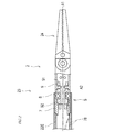
- FIG. 1 is a diagram showing a schematic configuration of a medical device according to an embodiment of the present invention.
- FIG. 2 is a partially enlarged cross-sectional view of a medical device showing a schematic configuration of a wrist joint.
- FIG. 3 is a side view of the shaft cover.
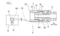
- FIG. 4 is a cross-sectional view illustrating a schematic configuration of the turning device.
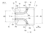
- FIG. 5 is a view taken in the direction of arrow V in FIG. 6 is a cross-sectional view taken along the line VI-VI in FIG.
- FIG. 7 is a partially enlarged cross-sectional view of a medical device showing a schematic configuration of a wrist joint of the medical device according to Modification 1.
- FIG. 8 is a diagram illustrating an example of an interlocking mechanism included in the turning device.
- FIG. 1 is a diagram showing a schematic configuration of a medical device 1 according to an embodiment of the present invention.
- the medical device 1 is a so-called medical manipulator, and includes an elongated shaft-like robot arm 2 and an end effector 24 connected to the tip of the robot arm 2.
- the robot arm 2 is provided between a base 21 provided at the proximal end, a wrist joint 23 provided at the distal end, a soft shaft 26 connected to the base 21, and the soft shaft 26 and the wrist joint 23.
- a plurality of links 22 and an intermediate joint 25 connecting the plurality of links 22 are provided.
- the base 21 is connected to a moving mechanism and a driving mechanism (not shown).
- the flexible shaft 26 is rotatably connected to the base 21.
- the flexible shaft 26 has flexibility and torque transmission property that transmits the input torque to the link 22 on the proximal end side among the plurality of links 22.
- the plurality of links 22 are rigid cylindrical members, and wires and wirings are inserted therein.
- the wrist joint 23 connects the end effector 24 to the tip link 22 among the plurality of links 22 so as to be rotatable.
- the end effector 24 means an actual operated part that is inserted into a surgical site in a patient's abdominal cavity and can be driven from the outside of the abdominal cavity to perform a desired processing or medical function of a target tissue in the surgical site.
- the end effector 24 may be a surgical tool such as a forceps, a gripper, a scissors, a stapler, a needle holder, and an electric knife.
- the end effector 24 may be an electrically driven device such as an electrosurgical electrode, a transducer, or a sensor.
- the end effector 24 may be a nozzle that supplies fluid for inhalation, gas injection, cleaning, processing fluid, accessory introduction, biopsy extraction, and the like.
- the end effector 24 may be mounted with an imaging device such as a camera.
- the medical device 1 means a medical device having the end effector 24 described above.
- the medical device 1 may be directly operated by a surgeon, or may be remotely operated by a remote surgical system using a robot or the like.
- FIG. 2 is a partially enlarged cross-sectional view of the medical device 1 showing a schematic configuration of the wrist joint 23.
- the wrist joint 23 connects the end effector 24 with a link 22 (hereinafter referred to as “tip link 22 ⁇ / b> E”) provided on the most distal side among the links 22 provided in the robot arm 2. ing.
- the end effector 24 is rotatable with respect to the distal end link 22E around the first axis A1 (swing axis) of the wrist joint 23. Further, the end effector 24 is rotatable with respect to the distal end link 22E around the second axis A2 (oscillation axis) of the wrist joint 23 orthogonal to the first axis A1.
- a direction parallel to the extending direction of the first axis A1 is referred to as an “axial direction Da”.
- the wrist joint 23 supports the shaft cover 7 coupled to the distal end link 22E, the pivot shaft 9 coupled to the end effector 24, and the pivot shaft 9 so as to be rotatable about the first axis A1 with respect to the shaft cover 7.
- a turning device S generally constituted by a bearing 8 and a drive mechanism 10 that rotationally drives the turning shaft 9 with respect to the shaft cover 7.
- the turning shaft 9 is a cylindrical shaft member extending in the axial direction Da, and the first axis A1 passes through the axis.
- Wirings such as a plurality of wires and sensor cables are inserted through the turning shaft 9. Examples of wirings inserted through the turning shaft 9 include an operation wire for operating the end effector 24, an operation wire for rotating the end effector 24 about the second axis A2, and a sensor provided on the end effector 24. Cable etc. are included.
- the tip 91 of the pivot shaft 9 is pin-joined with the base of the end effector 24.
- the mode of pin joining is not limited, for example, it is realized by a pin that protrudes in parallel with the second axis A2 from the base of the end effector 24 and a support hole formed in the distal end portion 91 of the pivot shaft 9 that supports the pin. be able to.
- the base 92 of the turning shaft 9 is inserted into the shaft cover 7. On the outer surface of the base 92 of the pivot shaft 9, a step surface 93 due to the difference in the outer diameter of the pivot shaft 9 is formed.
- the bearing 8 is disposed between the distal end portion 91 of the turning shaft 9 and the axial direction Da of the base portion 92.
- FIG. 3 is a side view of the shaft cover 7
- FIG. 4 is a cross-sectional view showing a schematic configuration of the swivel device S
- FIG. 5 is a cross-sectional view taken along the arrow V in FIG. .
- the operation wire 78 wired to the guide 74 of the shaft cover 7 is lightly painted and indicated by a two-dot chain line (virtual line).
- the operation wire 78 wired to the guide 74 of the shaft cover 7 is lightly painted and indicated by a two-dot chain line
- the turning shaft 9 inserted into the shaft cover 7 is indicated by a two-dot chain line.
- the shaft cover 7 has a cylindrical wall 70 extending in the axial direction Da.
- a notch 73 continuous in the circumferential direction is provided at the base end edge of the outer surface of the wall 70. Using this notch 73, the shaft cover 7 and the end link 22E are coupled.
- the shaft cover 7 is formed symmetrically about a symmetry plane P1 passing through the axis of the shaft cover 7 and parallel to the axial direction Da.
- the shaft cover 7 is formed with a guide 74 for guiding the operation wire 78.
- the guides 74 are formed symmetrically on one side and the other side via the symmetry plane P1.
- the guide 74 forms a wiring path of the operation wire 78 in the shaft cover 7, and one operation wire 78 is wired for each guide 74.
- An operation wire 78 wired to the guide 74 is a wire for turning the turning shaft 9.
- the operation wire 78 according to the present embodiment is an endless wire and is wound around the turning shaft 9 and a pulley 77 disposed on the base 21. A portion of the operation wire 78 between the pivot shaft 9 and the pulley 77 is passed through the link 22.
- the operation wire 78 is wound around the outer peripheral surface of the turning shaft 9 in the circumferential direction, and is fixed to the turning shaft 9 on the outer peripheral surface of the turning shaft 9.
- the pulley 77 is driven to rotate forward and backward by a drive source (not shown). The operation of this drive source is controlled by a control device (not shown). By the forward and reverse rotation of the pulley 77, the operation wire 78 is pulled and loosened, and the turning shaft 9 rotates about the first axis A1.
- the manner in which the operation wire 78 is fixed to the pivot shaft 9 is not limited.
- a recess or hole provided in the outer peripheral surface of the pivot shaft 9 and a part of the operation wire 78 fitted in a ring in the recess or hole are provided.
- a part of the operation wire 78 can be fastened to the pivot shaft 9 with the pin that prevents the pin from coming off.
- the fastening width (circumferential width) of the operation wire 78 to the turning shaft 9 is smaller.
- the operation wire 78 is not endless and may be divided into a plurality of pieces.
- the operation wire 78 when the operation wire 78 is divided on the outer peripheral surface of the turning shaft 9, one end portion and the other end portion of the operation wire 78 are arranged close to each other on the outer surface of the turning shaft 9, and Each may be coupled to the pivot axis 9. Further, for example, when the operation wire 78 is divided at a portion wound around the pulley 77, a plurality of pulleys 77 are provided, and each of the divided ends of the operation wire 78 is connected to a different pulley 77. It may be wound. A plurality of operation wires 78 may be wound around one turning shaft 9. In this case, a number of guides 74 corresponding to the number of operation wires 78 are provided on the shaft cover 7.
- the guide 74 smoothly connects the outer peripheral portion 743 formed on the outer surface of the wall 70 of the shaft cover 7, the inner peripheral portion 744 formed along the inner surface of the wall 70, and the outer peripheral portion 743 and the inner peripheral portion 744. Connecting portions 745 to be connected to both sides via the plane of symmetry P1.
- the outer peripheral portion 743 of the guide 74 is a groove (that is, a continuous recess) formed on the outer surface of the wall 70.
- the outer peripheral portion 743 has a base end of the wall 70 as a start point 741, and extends in the axial direction Da from the start point 741 to a midway portion of the wall 70 in the axial direction Da.
- the central angle between the starting point 741 on one side and the starting point 741 on the other side is about 45 ° via the symmetry plane P1.
- the depth direction Dt of the groove of the outer peripheral portion 743 does not coincide with the radial direction of the shaft cover 7 and is inclined from the radial direction. Thereby, a deeper groove can be formed in the wall having a limited thickness.
- the depth direction Dt of the outer peripheral portion 743 on one side and the depth direction Dt of the outer peripheral portion 743 on the other side intersect on the symmetry plane P1 via the symmetry plane P1.
- the inner peripheral portion 744 of the guide 74 is formed by the cooperation of the shaft cover 7 and the turning shaft 9.
- a large diameter portion 71 having a first inner diameter ⁇ 1 On the inner surface of the wall 70 of the shaft cover 7, a large diameter portion 71 having a first inner diameter ⁇ 1, a small diameter portion 72 having a second inner diameter ⁇ 2, and a step due to a difference in inner diameter between the large diameter portion 71 and the small diameter portion 72.
- a surface 75 is formed.
- the second inner diameter ⁇ 2 is smaller than the first inner diameter ⁇ 1, and the large diameter portion 71 is located on the distal end side of the small diameter portion 72.
- the stepped surface 75 of the shaft cover 7 and the stepped surface 93 of the turning shaft 9 are opposed to each other with a gap in the axial direction Da.
- An annular space surrounded by the inner surface of the shaft cover 7 and the outer surface of the turning shaft 9 is formed between the step surfaces 75 and 93. At least a part of the annular space is used as the inner peripheral portion 744 of the guide 74.
- the inner peripheral portion 744 extends in the circumferential direction along the inner surface of the wall 70. In other words, the inner peripheral portion 744 of the guide 74 extends in the circumferential direction along the outer surface of the pivot shaft 9.
- An annular space surrounded by the inner surface of the shaft cover 7 and the outer surface of the pivot shaft 9 between the two step surfaces 75 and 93 is used as the inner peripheral portion 744 of the guide 74.
- the connection portion 745 of the guide 74 is formed by a communication hole 746 that penetrates the wall 70 inward and outward, and a groove (that is, a continuous recess) formed on the outer surface of the wall 70 that connects the communication hole 746 and the outer peripheral portion 743.
- the communication hole 746 extends in the tangential direction (circumferential direction) at the opening end 742 from the opening end 742 located on the large diameter portion 71 side immediately on the boundary between the large diameter portion 71 and the small diameter portion 72 of the shaft cover 7.
- An inner peripheral portion 744 of the guide 74 exists inside the communication hole 746.
- the center angle of the opening end 742 on one side and the opening end 742 on the other side through the symmetry plane P1 of the guide 74 is approximately 180 ° (see FIG. 6).
- the groove connecting the communication hole 746 and the outer peripheral portion 743 in the connecting portion 745 gently connects the outer peripheral portion 743 extending in the axial direction Da and the inner peripheral portion 744 extending in the circumferential direction with an arcuate curve.
- the radius of curvature of the connection portion 745 is sufficiently large so that the operation wire 78 can smoothly pass through the connection portion 745.
- the operation wire 78 wired to the guide 74 of the shaft cover 7 having the above configuration extends in the axial direction Da at the outer peripheral portion 743, extends in the circumferential direction at the inner peripheral portion 744, and circumferentially from the axial direction Da at the connecting portion 745.
- the stretching direction is gradually changed.
- the operation wire 78 wired to the guide 74 of the shaft cover 7 as described above, a part of the operation wire 78 and the other part do not interfere with each other. That is, the operation wire 78 does not cross or overlap at the wrist joint 23.
- the swivel device S of the present embodiment extends in the axial direction Da inserted into the inner side of the wall 70 of the shaft cover 7 and the shaft cover 7 having the cylindrical wall 70 extending in the axial direction Da.
- a pivot shaft 9, a bearing 8 that allows the shaft cover 7 to pivotally support the pivot shaft 9 about its axis, and an operation wire 78 coupled to the pivot shaft 9 inside the wall 70 of the shaft cover 7 are provided.
- the shaft cover 7 has a guide 74 for guiding the operation wire 78.
- the guide 74 is formed in plane symmetry via a plane of symmetry P1 that passes through the axis of the shaft cover 7 and is parallel to the axial direction Da.
- the guide 74 includes an outer peripheral portion 743 extending in the axial direction Da from the base end of the wall 70 formed on the outer surface of the wall 70, and an inner peripheral portion 744 extending along the circumferential direction formed along the inner surface of the wall 70.
- the connecting portion 745 that connects the outer peripheral portion 743 and the inner peripheral portion 744 is provided on both sides via the symmetry plane P1.
- the acting direction of the pulling force applied to the operation wire 78 is from the start point 741 of the guide 74 to the swivel axis 9. It changes in the wiring route to the outer surface.
- the degree of change in the acting direction of the pulling force applied to the operation wire 78 is reduced by the operation wire 78 being routed along the guide 74. That is, when the operation wire 78 is guided by the guide 74, a sudden change in the direction of action of the tensile force applied to the operation wire 78 is avoided. Therefore, it is possible to avoid that the operation wire 78 is partially subjected to an excessive load or drooped.
- the guide 74 of the shaft cover 7 continues straight from the start point 741 provided on one side to the start point 741 provided on the other side via the symmetry plane P1, and overlaps in the middle. Have not crossed. Therefore, a part of the operation wire 78 wired to the guide 74 and the other part do not interfere with each other.
- a guide 74 that is independent from other guides 74 and does not overlap or intersect is formed on the shaft cover 7 for each operation wire 78.
- the operation wire 78 is guided so that a part of one operation wire 78 and another part or a plurality of operation wires 78 do not interfere with each other. Therefore, it is possible to avoid a change in the control characteristics of the operation wire 78 due to a frictional force generated by interference between the operation wires 78 or portions thereof.
- connection portion 745 connects the communication hole 746 that penetrates the wall 70 inward and outward and opens to the inner peripheral portion 744, and the communication hole 746 and the outer peripheral portion 743 in a curved shape. It is formed by the groove
- connection part 745 a part of the operation wire 78 guided by the outer peripheral part 743 and extending in the axial direction Da and another part of the operation wire 78 guided by the inner peripheral part 744 and extending in the circumferential direction are guided to the connection part 745.
- the operation wire 78 is further loosely (smoothly) joined by another portion. Therefore, it is possible to avoid the operation wire 78 from being partially subjected to an excessive load, broken, or twisted.
- the communication hole 746 of the connection portion 745 extends from the opening end 742 in the tangential direction at the opening end 742.
- the portion of the operation wire 78 passing through the communication hole 746 extends in the tangential direction of the opening end 742 and is more smoothly connected to the portion guided by the inner peripheral portion 744 of the operation wire 78. .
- the wall 70 of the shaft cover 7 has an annular first step surface 75 facing one of the axial directions Da on the inner surface, and the swiveling shaft 9 has an axial direction Da on the outer surface.
- the second step surface 93 has an annular shape facing the other, and the step surfaces 75 and 93 are arranged so as to face each other in the axial direction Da.
- An inner peripheral portion 744 of the guide 74 is formed between the step surfaces 75 and 93 by the inner surface of the shaft cover 7 and the outer surface of the pivot shaft 9.
- the inner peripheral portion 744 of the guide 74 can be formed on the inner surface of the wall 70 without forming a groove by machining on the inner surface of the wall 70 of the shaft cover 7 which is difficult to machine.
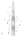
- FIG. 7 is a partially enlarged cross-sectional view of the medical device 1 showing a schematic configuration of the wrist joint 23 of the medical device 1 according to the first modification.
- the same or similar members as those in the above-described embodiment may be denoted by the same reference numerals in the drawings, and description thereof may be omitted.
- the wrist joint 23 of the medical device 1 according to the modified example 1 is connected in the axial direction Da with the turning shaft 9, the shaft cover 7, the bearing 8, and the operation wire 78 as one turning unit.
- a turning device S including a plurality of turning units is provided.
- the two turning units U1 and U2 are connected in series via the connecting member 79 (or directly).
- the turning shaft 9 is connected to the end effector 24, and the shaft cover 7 is connected to the cylindrical connecting member 79.
- the turning shaft 9 is coupled to the connecting member 79, and the shaft cover 7 is coupled to the tip link 22E.
- the winding range of the operation wire 78 around the turning shaft 9 is less than one turn, so the turning range of the turning shaft 9 is less than 360 °.
- the swivel device S includes a plurality of swivel units U1 and U2 arranged in series as in this modification, the swivel range of the swivel shaft 9 can be increased. .
- the operation wire 78 (78A) of the swivel unit U1 and the operation wire 78 (78B) of the swivel unit U2 can be directly or indirectly coupled.
- U1 and swivel unit U2 can be interlocked.
- the operation wire 78A of the turning unit U1 and the operation wire 78B of the turning unit U2 move at the same amount and at the same speed.
- the coupling between the operation wire 78A of the swivel unit U1 and the operation wire 78B of the swivel unit U2 can be released, and the swivel unit U1 and the swivel unit U2 can be operated independently by releasing the coupling. .
- the end effector 24 (the turning shaft 9 of the turning unit U1) is rotated faster than when the turning unit U1 and the turning unit U2 are operated independently. be able to. That is, when the operation wire 78 is pulled at the same amount and at the same speed, when the turning unit U1 and the turning unit U2 are interlocked, the end is compared with the case where the turning unit U1 and the turning unit U2 are operated independently. The amount of rotation of the effector 24 is large.
- the interlocking and independent of the turning unit U1 and the turning unit U2 can be selected, the turning around the first axis A1 of the end effector 24 can be controlled more finely.
- the turning device S according to the first modification includes an interlocking mechanism that switches between interlocking and independent of the turning unit U1 and the turning unit U2.
- the interlocking mechanism is, for example, a mechanism for coupling and releasing coupling of operation wires that can be operated simultaneously between a plurality of turning units.
- the interlocking mechanism according to this modification can couple and release the operation wire 78A of the turning unit U1 and the operation wire 78B of the turning unit U2.
- such a mechanism has a pulley 77A around which the operation wire 78A of the turning unit U1 is wound and a pulley 77B around which the operation wire 78B of the turning unit U2 is wound coaxially.
- This can be realized by providing an engagement / disengagement device 80 such as a clutch for switching between engagement and disengagement of the pulleys 77A and 77B arranged on the same axis.
- the above configuration can be modified as follows, for example.
- the turning device S is applied to the wrist joint 23, a similar turning device S may be applied to the intermediate joint 25.
Landscapes
- Engineering & Computer Science (AREA)
- Health & Medical Sciences (AREA)
- Robotics (AREA)
- Surgery (AREA)
- Life Sciences & Earth Sciences (AREA)
- Mechanical Engineering (AREA)
- Medical Informatics (AREA)
- Heart & Thoracic Surgery (AREA)
- Biomedical Technology (AREA)
- Molecular Biology (AREA)
- Animal Behavior & Ethology (AREA)
- General Health & Medical Sciences (AREA)
- Public Health (AREA)
- Veterinary Medicine (AREA)
- Nuclear Medicine, Radiotherapy & Molecular Imaging (AREA)
- Manipulator (AREA)
Abstract
Description
軸方向に延びる筒形状の壁を有する軸カバーと、
前記軸カバーの前記壁の内側に挿入された前記軸方向に延びる旋回軸と、
前記軸カバーに前記旋回軸をその軸心まわりに回動可能に支持させる軸受と、
前記軸カバーの前記壁の内側において前記旋回軸と結合された少なくとも1本の操作ワイヤとを備え、
前記軸カバーは、前記少なくとも1本の操作ワイヤを案内するためのガイドを有し、
前記ガイドは、前記軸カバーの軸心を通り且つ前記軸方向と平行な対称面を介して面対称に形成されており、前記壁の外面に形成された前記壁の基端から前記軸方向に延びる外周部分と、前記壁の内面に沿って形成された円周方向に延びる内周部分と、前記外周部分と前記内周部分を接続する接続部分とを前記対称面を介して両側に有することを特徴としている。 A turning device according to one aspect of the present invention is a turning device provided at a joint of a robot arm,
A shaft cover having a cylindrical wall extending in the axial direction;
A pivot shaft extending in the axial direction and inserted inside the wall of the shaft cover;
A bearing that allows the pivot cover to pivotally support the pivot shaft about its axis;
At least one operation wire coupled to the pivot shaft inside the wall of the shaft cover;
The shaft cover has a guide for guiding the at least one operation wire,
The guide is formed in plane symmetry via a plane of symmetry passing through the axis of the shaft cover and parallel to the axial direction, and from the base end of the wall formed on the outer surface of the wall in the axial direction. An outer peripheral portion that extends, an inner peripheral portion that extends in the circumferential direction formed along the inner surface of the wall, and a connection portion that connects the outer peripheral portion and the inner peripheral portion are provided on both sides via the symmetry plane. It is characterized by.
2 :ロボットアーム
7 :軸カバー
71 :大径部分
72 :小径部分
73 :切欠き
74 :ガイド
741 :始点
742 :開口端
743 :外周部分
744 :内周部分
745 :接続部分
746 :連通孔
75 :段差面
8 :軸受
9 :旋回軸
10 :駆動機構
21 :ベース
22,22E :リンク
23 :手首関節
24 :エンドエフェクタ
25 :中間関節
26 :軟性シャフト
77 :プーリ
78(78A,78B):操作ワイヤ
79 :連結部材
80 :係脱装置
A1 :第1軸
A2 :第2軸
S :旋回装置
U1,U2 :旋回ユニット 1: Medical device 2: Robot arm 7: Shaft cover 71: Large diameter part 72: Small diameter part 73: Notch 74: Guide 741: Start point 742: Open end 743: Outer peripheral part 744: Inner peripheral part 745: Connection part 746: Communication hole 75: Step surface 8: Bearing 9: Rotating shaft 10: Drive mechanism 21:
Claims (7)
- ロボットアームの関節に設けられた旋回装置であって、
軸方向に延びる筒形状の壁を有する軸カバーと、
前記軸カバーの前記壁の内側に挿入された前記軸方向に延びる旋回軸と、
前記軸カバーに前記旋回軸をその軸心まわりに回動可能に支持させる軸受と、
前記軸カバーの前記壁の内側において前記旋回軸と結合された少なくとも1本の操作ワイヤとを備え、
前記軸カバーは、前記少なくとも1本の操作ワイヤを案内するためのガイドを有し、
前記ガイドは、前記軸カバーの軸心を通り且つ前記軸方向と平行な対称面を介して面対称に形成されており、前記壁の外面に形成された前記壁の基端から前記軸方向に延びる外周部分と、前記壁の内面に沿って形成された円周方向に延びる内周部分と、前記外周部分と前記内周部分を接続する接続部分とを前記対称面を介して両側に有する、
旋回装置。 A swivel device provided at the joint of the robot arm,
A shaft cover having a cylindrical wall extending in the axial direction;
A pivot shaft extending in the axial direction and inserted inside the wall of the shaft cover;
A bearing that allows the pivot cover to pivotally support the pivot shaft about its axis;
At least one operation wire coupled to the pivot shaft inside the wall of the shaft cover;
The shaft cover has a guide for guiding the at least one operation wire,
The guide is formed in plane symmetry via a plane of symmetry passing through the axis of the shaft cover and parallel to the axial direction, and from the base end of the wall formed on the outer surface of the wall in the axial direction. An outer peripheral portion that extends, an inner peripheral portion that extends in the circumferential direction formed along the inner surface of the wall, and a connection portion that connects the outer peripheral portion and the inner peripheral portion on both sides via the symmetry plane;
Swivel device. - 前記接続部分が、前記壁を内外に貫き且つ前記内周部分に開口している連通孔と、前記連通孔と前記外周部分とを曲線状に接続する前記壁の外面に設けられた溝とにより形成されている、請求項1に記載の旋回装置。 The connecting portion includes a communication hole that penetrates the wall inward and outward and is open to the inner peripheral portion, and a groove provided on an outer surface of the wall that connects the communication hole and the outer peripheral portion in a curved shape. The swivel device according to claim 1 formed.
- 前記連通孔が、その開口端から当該開口端における接線方向に延びている、請求項2に記載の旋回装置。 The turning device according to claim 2, wherein the communication hole extends in a tangential direction at the opening end from the opening end.
- 前記軸カバーの前記壁は内面に前記軸方向のうち一方を向いた環状の第1の段差面を有し、
前記旋回軸は外面に前記軸方向のうち他方を向いた環状の第2の段差面を有し、
前記第1の段差面と前記第2の段差面が前記軸方向に間を開けて対峙するように配置され、前記第1の段差面と前記第2の段差面の間において前記軸カバーの内面と前記旋回軸の外面によって前記内周部分が形成されている、請求項1~3のいずれか一項に記載の旋回装置。 The wall of the shaft cover has an annular first step surface facing one of the axial directions on the inner surface;
The swivel shaft has an annular second step surface facing the other of the axial directions on the outer surface;
The first step surface and the second step surface are arranged so as to face each other with a gap in the axial direction, and the inner surface of the shaft cover is located between the first step surface and the second step surface. The turning device according to any one of claims 1 to 3, wherein the inner peripheral portion is formed by an outer surface of the turning shaft. - 前記旋回軸、前記軸カバー、前記軸受、及び、前記少なくとも1本の操作ワイヤを1つの旋回ユニットとして、前記軸方向に連結された複数の前記旋回ユニットを備える、請求項1~4のいずれか一項に記載の旋回装置。 The rotating shaft, the shaft cover, the bearing, and the at least one operation wire as a single swiveling unit, comprising a plurality of swiveling units connected in the axial direction. The swivel device according to one item.
- 前記複数の旋回ユニット間の前記少なくとも1本の操作ワイヤを結合して、前記複数の旋回ユニットを連動させる連動機構を更に備える、請求項5に記載の旋回装置。 The swivel device according to claim 5, further comprising an interlocking mechanism for coupling the plurality of swivel units by coupling the at least one operation wire between the plurality of swivel units.
- 請求項1~6のいずれか一項に記載の旋回装置を具備するロボットアームと、
前記ロボットアームの先端に設けられたエンドエフェクタとを備える、
医療機器。 A robot arm comprising the turning device according to any one of claims 1 to 6;
An end effector provided at the tip of the robot arm,
Medical equipment.
Priority Applications (6)
| Application Number | Priority Date | Filing Date | Title |
|---|---|---|---|
| EP15897637.3A EP3321046B1 (en) | 2015-07-09 | 2015-07-09 | Turning device and medical instrument |
| JP2017526784A JP6600357B2 (en) | 2015-07-09 | 2015-07-09 | Swivel device and medical device |
| KR1020187003231A KR102032379B1 (en) | 2015-07-09 | 2015-07-09 | Turning device and medical device |
| PCT/JP2015/003485 WO2017006374A1 (en) | 2015-07-09 | 2015-07-09 | Slewing device and surgical instrument |
| CN201580080187.3A CN107530889A (en) | 2015-07-09 | 2015-07-09 | Revolving gear and medicine equipment |
| US15/742,895 US20180215051A1 (en) | 2015-07-09 | 2015-07-09 | Turning device and medical instrument |
Applications Claiming Priority (1)
| Application Number | Priority Date | Filing Date | Title |
|---|---|---|---|
| PCT/JP2015/003485 WO2017006374A1 (en) | 2015-07-09 | 2015-07-09 | Slewing device and surgical instrument |
Publications (1)
| Publication Number | Publication Date |
|---|---|
| WO2017006374A1 true WO2017006374A1 (en) | 2017-01-12 |
Family
ID=57685072
Family Applications (1)
| Application Number | Title | Priority Date | Filing Date |
|---|---|---|---|
| PCT/JP2015/003485 WO2017006374A1 (en) | 2015-07-09 | 2015-07-09 | Slewing device and surgical instrument |
Country Status (6)
| Country | Link |
|---|---|
| US (1) | US20180215051A1 (en) |
| EP (1) | EP3321046B1 (en) |
| JP (1) | JP6600357B2 (en) |
| KR (1) | KR102032379B1 (en) |
| CN (1) | CN107530889A (en) |
| WO (1) | WO2017006374A1 (en) |
Cited By (2)
| Publication number | Priority date | Publication date | Assignee | Title |
|---|---|---|---|---|
| JP2019042903A (en) * | 2017-09-06 | 2019-03-22 | 川崎重工業株式会社 | Robot arm |
| US11219496B2 (en) | 2017-03-24 | 2022-01-11 | Medicaroid Corporation | Surgical tool, medical treatment instrument, and surgical system |
Families Citing this family (3)
| Publication number | Priority date | Publication date | Assignee | Title |
|---|---|---|---|---|
| JP6150962B1 (en) * | 2015-07-17 | 2017-06-21 | オリンパス株式会社 | manipulator |
| JP6811676B2 (en) * | 2017-05-01 | 2021-01-13 | 株式会社メディカロイド | Drive member, drive mechanism, and manufacturing method of drive mechanism |
| US11096754B2 (en) | 2017-10-04 | 2021-08-24 | Mako Surgical Corp. | Sterile drape assembly for surgical robot |
Citations (4)
| Publication number | Priority date | Publication date | Assignee | Title |
|---|---|---|---|---|
| JP2008212451A (en) * | 2007-03-06 | 2008-09-18 | Nagoya Institute Of Technology | Surgical manipulator |
| US20100160929A1 (en) * | 2008-12-23 | 2010-06-24 | Rogers Theodore W | roll joint and method for a surgical apparatus |
| WO2012049623A1 (en) * | 2010-10-11 | 2012-04-19 | Ecole Polytechnique Federale De Lausanne (Epfl) | Mechanical manipulator for surgical instruments |
| US20150073434A1 (en) * | 2012-04-20 | 2015-03-12 | Vanderbilt University | Dexterous wrists for surgical intervention |
Family Cites Families (10)
| Publication number | Priority date | Publication date | Assignee | Title |
|---|---|---|---|---|
| US20060199999A1 (en) * | 2001-06-29 | 2006-09-07 | Intuitive Surgical Inc. | Cardiac tissue ablation instrument with flexible wrist |
| US7090637B2 (en) * | 2003-05-23 | 2006-08-15 | Novare Surgical Systems, Inc. | Articulating mechanism for remote manipulation of a surgical or diagnostic tool |
| US8567265B2 (en) * | 2006-06-09 | 2013-10-29 | Endosense, SA | Triaxial fiber optic force sensing catheter |
| CN100560308C (en) * | 2007-09-27 | 2009-11-18 | 上海交通大学 | Safe type mechanical arm |
| WO2011108142A1 (en) * | 2010-03-03 | 2011-09-09 | オリンパスメディカルシステムズ株式会社 | Treatment device |
| KR101126288B1 (en) * | 2010-07-02 | 2012-03-20 | 한국과학기술원 | Surgery tools with rolling of end effector for minimally invasive surgery |
| JP2012065975A (en) * | 2010-09-27 | 2012-04-05 | Terumo Corp | Medical manipulator |
| WO2014162511A1 (en) * | 2013-04-02 | 2014-10-09 | カール シュトルツ ゲゼルシャフト ミット ベシュレンクテル ハフツング ウント コンパニー コマンディートゲゼルシャフト | Medical manipulator |
| US10285763B2 (en) * | 2014-04-02 | 2019-05-14 | Intuitive Surgical Operations, Inc. | Actuation element guide with twisting channels |
| GB201521809D0 (en) * | 2015-12-10 | 2016-01-27 | Cambridge Medical Robotics Ltd | Symmetrically arranged surgical instrument articulation |
-
2015
- 2015-07-09 EP EP15897637.3A patent/EP3321046B1/en active Active
- 2015-07-09 KR KR1020187003231A patent/KR102032379B1/en active IP Right Grant
- 2015-07-09 US US15/742,895 patent/US20180215051A1/en not_active Abandoned
- 2015-07-09 CN CN201580080187.3A patent/CN107530889A/en active Pending
- 2015-07-09 JP JP2017526784A patent/JP6600357B2/en active Active
- 2015-07-09 WO PCT/JP2015/003485 patent/WO2017006374A1/en active Application Filing
Patent Citations (4)
| Publication number | Priority date | Publication date | Assignee | Title |
|---|---|---|---|---|
| JP2008212451A (en) * | 2007-03-06 | 2008-09-18 | Nagoya Institute Of Technology | Surgical manipulator |
| US20100160929A1 (en) * | 2008-12-23 | 2010-06-24 | Rogers Theodore W | roll joint and method for a surgical apparatus |
| WO2012049623A1 (en) * | 2010-10-11 | 2012-04-19 | Ecole Polytechnique Federale De Lausanne (Epfl) | Mechanical manipulator for surgical instruments |
| US20150073434A1 (en) * | 2012-04-20 | 2015-03-12 | Vanderbilt University | Dexterous wrists for surgical intervention |
Non-Patent Citations (1)
| Title |
|---|
| See also references of EP3321046A4 * |
Cited By (3)
| Publication number | Priority date | Publication date | Assignee | Title |
|---|---|---|---|---|
| US11219496B2 (en) | 2017-03-24 | 2022-01-11 | Medicaroid Corporation | Surgical tool, medical treatment instrument, and surgical system |
| JP2019042903A (en) * | 2017-09-06 | 2019-03-22 | 川崎重工業株式会社 | Robot arm |
| JP7011426B2 (en) | 2017-09-06 | 2022-01-26 | 川崎重工業株式会社 | Manipulator system |
Also Published As
| Publication number | Publication date |
|---|---|
| CN107530889A (en) | 2018-01-02 |
| JPWO2017006374A1 (en) | 2018-04-19 |
| US20180215051A1 (en) | 2018-08-02 |
| EP3321046B1 (en) | 2020-03-18 |
| EP3321046A1 (en) | 2018-05-16 |
| KR20180026496A (en) | 2018-03-12 |
| JP6600357B2 (en) | 2019-10-30 |
| KR102032379B1 (en) | 2019-10-15 |
| EP3321046A4 (en) | 2019-04-03 |
Similar Documents
| Publication | Publication Date | Title |
|---|---|---|
| JP6600357B2 (en) | Swivel device and medical device | |
| US10881475B2 (en) | Surgical robot | |
| US20170135710A1 (en) | Medical treatment instrument | |
| US10864052B2 (en) | Surgical instrument with articulated end-effector | |
| RU2551932C2 (en) | Minimally invasive laparoscopic surgical forceps | |
| US6676684B1 (en) | Roll-pitch-roll-yaw surgical tool | |
| US20180214220A1 (en) | Surgical robot | |
| US10159473B2 (en) | Actuation cable having multiple friction characteristics | |
| US11071600B2 (en) | Medical treatment tool and surgical system | |
| WO2017006373A1 (en) | Joint for robot arm, and surgical instrument | |
| WO2015107999A1 (en) | Joint mechanism, manipulator, and manipulator system | |
| JP2004122286A (en) | Manipulator | |
| JP2008237810A (en) | Multi-joint bending mechanism and medical instrument with multi-joint bending mechanism | |
| US20160135911A1 (en) | Treatment manipulator and manipulator system | |
| JP6404537B1 (en) | Medical treatment tool | |
| WO2012043463A1 (en) | Medical manipulator | |
| US11324560B2 (en) | Surgical instrument | |
| US20180318024A1 (en) | Medical instrument | |
| JP2020073013A (en) | Surgical system and medical treatment device |
Legal Events
| Date | Code | Title | Description |
|---|---|---|---|
| 121 | Ep: the epo has been informed by wipo that ep was designated in this application |
Ref document number: 15897637 Country of ref document: EP Kind code of ref document: A1 |
|
| ENP | Entry into the national phase |
Ref document number: 2017526784 Country of ref document: JP Kind code of ref document: A |
|
| WWE | Wipo information: entry into national phase |
Ref document number: 15742895 Country of ref document: US |
|
| NENP | Non-entry into the national phase |
Ref country code: DE |
|
| ENP | Entry into the national phase |
Ref document number: 20187003231 Country of ref document: KR Kind code of ref document: A |
|
| WWE | Wipo information: entry into national phase |
Ref document number: 2015897637 Country of ref document: EP |