WO2016208950A1 - Method for transmitting/receiving data in wireless communication system, and device for same - Google Patents
Method for transmitting/receiving data in wireless communication system, and device for same Download PDFInfo
- Publication number
- WO2016208950A1 WO2016208950A1 PCT/KR2016/006595 KR2016006595W WO2016208950A1 WO 2016208950 A1 WO2016208950 A1 WO 2016208950A1 KR 2016006595 W KR2016006595 W KR 2016006595W WO 2016208950 A1 WO2016208950 A1 WO 2016208950A1
- Authority
- WO
- WIPO (PCT)
- Prior art keywords
- terminal
- context
- information
- base station
- message
- Prior art date
Links
Images


Classifications
-
- H—ELECTRICITY
- H04—ELECTRIC COMMUNICATION TECHNIQUE
- H04L—TRANSMISSION OF DIGITAL INFORMATION, e.g. TELEGRAPHIC COMMUNICATION
- H04L63/00—Network architectures or network communication protocols for network security
- H04L63/12—Applying verification of the received information
- H04L63/126—Applying verification of the received information the source of the received data
-
- H—ELECTRICITY
- H04—ELECTRIC COMMUNICATION TECHNIQUE
- H04L—TRANSMISSION OF DIGITAL INFORMATION, e.g. TELEGRAPHIC COMMUNICATION
- H04L9/00—Cryptographic mechanisms or cryptographic arrangements for secret or secure communications; Network security protocols
- H04L9/08—Key distribution or management, e.g. generation, sharing or updating, of cryptographic keys or passwords
- H04L9/0861—Generation of secret information including derivation or calculation of cryptographic keys or passwords
- H04L9/0866—Generation of secret information including derivation or calculation of cryptographic keys or passwords involving user or device identifiers, e.g. serial number, physical or biometrical information, DNA, hand-signature or measurable physical characteristics
-
- H—ELECTRICITY
- H04—ELECTRIC COMMUNICATION TECHNIQUE
- H04L—TRANSMISSION OF DIGITAL INFORMATION, e.g. TELEGRAPHIC COMMUNICATION
- H04L9/00—Cryptographic mechanisms or cryptographic arrangements for secret or secure communications; Network security protocols
- H04L9/32—Cryptographic mechanisms or cryptographic arrangements for secret or secure communications; Network security protocols including means for verifying the identity or authority of a user of the system or for message authentication, e.g. authorization, entity authentication, data integrity or data verification, non-repudiation, key authentication or verification of credentials
- H04L9/3236—Cryptographic mechanisms or cryptographic arrangements for secret or secure communications; Network security protocols including means for verifying the identity or authority of a user of the system or for message authentication, e.g. authorization, entity authentication, data integrity or data verification, non-repudiation, key authentication or verification of credentials using cryptographic hash functions
- H04L9/3242—Cryptographic mechanisms or cryptographic arrangements for secret or secure communications; Network security protocols including means for verifying the identity or authority of a user of the system or for message authentication, e.g. authorization, entity authentication, data integrity or data verification, non-repudiation, key authentication or verification of credentials using cryptographic hash functions involving keyed hash functions, e.g. message authentication codes [MACs], CBC-MAC or HMAC
-
- H—ELECTRICITY
- H04—ELECTRIC COMMUNICATION TECHNIQUE
- H04W—WIRELESS COMMUNICATION NETWORKS
- H04W12/00—Security arrangements; Authentication; Protecting privacy or anonymity
- H04W12/10—Integrity
-
- H—ELECTRICITY
- H04—ELECTRIC COMMUNICATION TECHNIQUE
- H04W—WIRELESS COMMUNICATION NETWORKS
- H04W12/00—Security arrangements; Authentication; Protecting privacy or anonymity
- H04W12/10—Integrity
- H04W12/106—Packet or message integrity
-
- H—ELECTRICITY
- H04—ELECTRIC COMMUNICATION TECHNIQUE
- H04W—WIRELESS COMMUNICATION NETWORKS
- H04W28/00—Network traffic management; Network resource management
- H04W28/02—Traffic management, e.g. flow control or congestion control
- H04W28/06—Optimizing the usage of the radio link, e.g. header compression, information sizing, discarding information
-
- H—ELECTRICITY
- H04—ELECTRIC COMMUNICATION TECHNIQUE
- H04W—WIRELESS COMMUNICATION NETWORKS
- H04W4/00—Services specially adapted for wireless communication networks; Facilities therefor
- H04W4/06—Selective distribution of broadcast services, e.g. multimedia broadcast multicast service [MBMS]; Services to user groups; One-way selective calling services
-
- H—ELECTRICITY
- H04—ELECTRIC COMMUNICATION TECHNIQUE
- H04W—WIRELESS COMMUNICATION NETWORKS
- H04W68/00—User notification, e.g. alerting and paging, for incoming communication, change of service or the like
- H04W68/005—Transmission of information for alerting of incoming communication
-
- H—ELECTRICITY
- H04—ELECTRIC COMMUNICATION TECHNIQUE
- H04W—WIRELESS COMMUNICATION NETWORKS
- H04W76/00—Connection management
- H04W76/20—Manipulation of established connections
-
- H—ELECTRICITY
- H04—ELECTRIC COMMUNICATION TECHNIQUE
- H04W—WIRELESS COMMUNICATION NETWORKS
- H04W8/00—Network data management
- H04W8/22—Processing or transfer of terminal data, e.g. status or physical capabilities
Definitions
- the present disclosure relates to a wireless communication system, and more particularly, to a method for transmitting and receiving end-to-end data and an apparatus supporting the same.
- Mobile communication systems have been developed to provide voice services while ensuring user activity.
- the mobile communication system has expanded not only voice but also data service.As a result of the explosive increase in traffic, a shortage of resources and users are demanding higher speed services, a more advanced mobile communication system is required. have.
- An object of the present specification is to provide a method for grouping a terminal context holding group according to a terminal context holding attribute (or terminal context holding level).
- an object of the present disclosure is to provide a method for transmitting information about a grouped terminal context holding group to a terminal.
- the present specification is to provide a method for transmitting and receiving end-to-end data according to the terminal context retention attribute.
- an object of the present specification is to provide a method for performing end-to-end connection establishment according to a terminal context retention attribute.
- the present disclosure provides a method for transmitting and receiving data in a wireless communication system, the method performed by a first network node, the method comprising: transmitting a control message including information related to a terminal context retention attribute to a terminal; Receiving a first message including a first information block from the terminal; Performing a verification procedure of the terminal based on the received first message; And transmitting a second message to the terminal according to the verification result of the terminal, wherein the terminal context holding attribute indicates at least one of whether the terminal context is retained or whether the terminal context can be changed.
- the method proposed in the present specification further comprises the step of confirming the terminal context retention attribute of the terminal based on the received first message.
- the first message may further include at least one of a header or a MAC-I field.
- the performing of the verification procedure of the terminal may include detecting a terminal context of the terminal based on a terminal identifier included in the first information block, and the terminal context of the terminal may be an integrity and an encryption key or At least one of security algorithm information; Generating an X-MAC for integrity proof based on the detected terminal context; And comparing the generated X-MAC with the MAC-I field included in the first message.
- the integrity and encryption key is characterized in that the regeneration according to a predetermined rule.
- the present specification if the verification of the terminal is successful, checking the state of the terminal; If the state of the terminal is in a connected state (connected state), and further comprising the step of performing a connection reset procedure with the terminal.
- the second message may include at least one of a header, a second information block, a third information block, or a MAC-I field.
- the third information block includes encrypted data
- the second information block includes a terminal identifier
- the first network node is grouped into a specific group according to a terminal context holding attribute.
- the method proposed in the present specification comprises the steps of receiving a paging indication message and downlink data from the second network node; And if the first message is not received within a predetermined time, deleting the received downlink data.
- the present disclosure provides a method for grouping one or more network nodes holding a terminal context in a wireless communication system, the method performed by a first network node, comprising: determining a terminal context holding group; And transmitting information related to the determined terminal context holding group to a terminal, wherein the terminal context holding group is divided according to a terminal context holding attribute, and the terminal context holding attribute may be a terminal context holding or a terminal context change possibility. It is characterized by indicating at least one of the presence or absence.
- the terminal context holding group may be determined using at least one of a speed of a terminal, a moving direction of the terminal, a state of the terminal, a supporting security algorithm, a security update policy, or network overhead.
- the terminal context holding group is configured by a terminal location update unit, a base station unit, or a cell unit.
- the location update unit of the terminal is characterized in that the tracking area, location area or RAN (Radio Access Network) level location area.
- RAN Radio Access Network
- the information related to the terminal context holding group includes at least one of group information indicating each group of the terminal context, terminal context holding attribute information indicating a terminal context holding attribute, or information indicating a grouping unit of the terminal context holding group. It is characterized by including.
- the method proposed in the present specification is characterized in that it further comprises the step of receiving information indicating the configuration of the terminal context from the second network node.
- the determining of the terminal context holding group in the present specification may further include receiving terminal context holding attribute information from at least one neighboring network node.
- the method proposed in the present specification may further include updating the determined terminal context holding group.
- the first network node is a base station
- the control message is system information
- the present specification is an apparatus for transmitting and receiving data in a wireless communication system
- the apparatus RF (Radio Frequency) unit for transmitting and receiving radio signals
- a processor operatively coupled to the RF unit, the processor further comprising: transmitting a control message to the terminal, the control message comprising information associated with a terminal context retention attribute; Receive a first message including a first information block from the terminal; Perform a verification procedure of the terminal based on the received first message; And controlling to transmit the second message to the terminal according to the verification result of the terminal, wherein the terminal context holding attribute indicates at least one of whether the terminal context is retained or whether the terminal context can be changed.
- RF Radio Frequency
- the present specification has an effect of reducing delay time for data transmission by informing the terminal of information about network nodes having the terminal context of the terminal.
- FIG. 1 is a diagram illustrating an example of an EPS (Evolved Packet System) related to an LTE system to which the technical features of the present specification can be applied.
- EPS Evolved Packet System
- FIG. 2 is a diagram illustrating a wireless communication system to which the technical features of the present specification can be applied.
- FIG. 3 is a block diagram illustrating an example of a functional split between an E-UTRAN and an EPC to which technical features of the present specification can be applied.
- 4A is a block diagram illustrating an example of a radio protocol architecture for a user plane to which technical features of the present specification can be applied.
- 4B is a block diagram illustrating an example of a radio protocol structure for a control plane to which technical features of the present specification can be applied.
- FIG. 5 is a diagram illustrating an S1 interface protocol structure in a wireless communication system to which technical features of the present specification can be applied.
- FIG. 6 is a diagram illustrating EMM and ECM states in a wireless communication system to which the present invention can be applied.
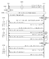
- FIG. 7 illustrates an example of a dedicated bearer activation procedure.
- FIG. 8 illustrates an example of a dedicated bearer deactivation procedure.
- FIG 9 is a diagram illustrating a handover procedure defined in LTE (-A).
- FIG. 10 is a diagram illustrating an operation process of a terminal and a base station in a contention based random access procedure.
- FIG. 11 is a flowchart illustrating an operation of a terminal in an RRC idle state to which the present invention can be applied.
- FIG. 12 is a flowchart illustrating a process of establishing an RRC connection to which the present invention can be applied.
- FIG. 13 is a flowchart illustrating a RRC connection resetting process to which the present invention can be applied.
- FIG. 14 illustrates an example of an RRC connection reestablishment procedure to which the present invention can be applied.
- 15 is a flowchart illustrating an example of a measurement performing method to which the present invention can be applied.
- 16A is a flowchart illustrating an example of a method for transmitting / receiving data of an idle terminal in a 3GPP EPS system.
- 16B is a flowchart illustrating an example of a data transmission / reception method of a connected state terminal in a 3GPP EPS system.
- 16C is a flowchart illustrating an example of a data transmission / reception method due to connection reconfiguration in a 3GPP EPS system.
- FIG. 17 illustrates an example of a structure of a wireless communication system for supporting a next generation RAN to which the methods proposed herein may be applied.
- 18A illustrates an example of a flow-based QoS structure to which the methods proposed herein may be applied.
- FIG. 18B is a diagram illustrating an example of a QoS structure used in a Qos framework to which the methods proposed herein may be applied.
- 19 is a flowchart illustrating an example of a method of grouping a group having a terminal context proposed in the present specification.
- 20 is a diagram illustrating an example of a method for grouping UE context-bearing network nodes according to a terminal location update unit proposed in the present specification.
- 21 is a flowchart illustrating an example of a method of determining a UE context retention group proposed herein.
- FIG. 22 is a flowchart illustrating still another example for determining a UE context holding group proposed in the present specification.
- 23 and 24 are flowcharts illustrating still another example of a method of determining a UE context holding group proposed herein.
- 25 is a flowchart illustrating an example of an operation method between network nodes according to update or release of a UE context proposed in the present specification.
- FIG. 26 is a diagram illustrating another example of an operation method between network nodes according to update or release of a UE context proposed in the present specification.
- FIG. 27 is a flowchart illustrating an example of a method for transmitting / receiving data according to a UE context retention attribute proposed in the present specification.
- FIG. 28 is a flowchart illustrating an example of a method for transmitting uplink data according to a UE context retention attribute proposed herein.
- FIG. 29 is a diagram illustrating an example of a method of operating a terminal in FIG. 28.
- FIG. 30 is a diagram illustrating an example of an operation method of a base station in FIG. 28.
- FIG. 31 is a flowchart illustrating an example of a method for receiving downlink data according to a UE context retention attribute proposed herein.
- 32 is a diagram illustrating an example of a paging base station group proposed in the present specification.
- 33 and 34 illustrate examples of an operation method of a terminal and a base station for receiving downlink data according to a UE context retention attribute proposed in the present specification.
- 35 is a flowchart illustrating still another example of a method for transmitting uplink data of a terminal according to a UE context retention attribute proposed herein.
- 36 and 37 are flowcharts illustrating still another examples of a method for receiving downlink data of a terminal according to a UE context retention attribute proposed herein.
- 38 is a flowchart illustrating still another example of a method for transmitting uplink data of a terminal according to a UE context retention attribute proposed herein.
- 39 is a flowchart illustrating still another example of a method for receiving downlink data of a terminal according to a UE context retention attribute proposed in the present specification.
- FIG. 40 is a flowchart illustrating still another example of a method for transmitting uplink data of a terminal according to a UE context retention attribute proposed herein.
- 41 is a diagram illustrating the operation of a terminal and a base station of FIG. 40.
- FIG. 42 is a flowchart illustrating still another example of a method for transmitting downlink data of a terminal according to a UE context retention attribute proposed herein.
- FIG. 42 is a flowchart illustrating still another example of a method for transmitting downlink data of a terminal according to a UE context retention attribute proposed herein.
- 43 is a flowchart illustrating still another example of a method for receiving downlink data according to a UE context retention attribute proposed in the present specification.
- FIG. 44 is a flowchart illustrating an example of a connection establishment procedure according to a UE context retention attribute proposed in the specification.
- FIG. 45 is a diagram illustrating an example of an information block used in FIG. 44.
- 46 is a flowchart illustrating still another example of a connection establishment procedure according to a UE context retention attribute proposed herein.
- FIG. 47 is a flowchart illustrating still another example of a connection establishment procedure according to a UE context retention attribute proposed herein.
- FIG. 47 is a flowchart illustrating still another example of a connection establishment procedure according to a UE context retention attribute proposed herein.
- FIG. 48 illustrates a block diagram of a wireless communication device to which the methods proposed herein can be applied.
- a base station has a meaning as a terminal node of a network that directly communicates with a terminal.
- the specific operation described as performed by the base station in this document may be performed by an upper node of the base station in some cases. That is, it is obvious that various operations performed for communication with a terminal in a network composed of a plurality of network nodes including a base station may be performed by the base station or other network nodes other than the base station.
- a 'base station (BS)' may be replaced by terms such as a fixed station, a Node B, an evolved-NodeB (eNB), a base transceiver system (BTS), an access point (AP), and the like. .
- a 'terminal' may be fixed or mobile, and may include a user equipment (UE), a mobile station (MS), a user terminal (UT), a mobile subscriber station (MSS), a subscriber station (SS), and an AMS ( Advanced Mobile Station (WT), Wireless Terminal (WT), Machine-Type Communication (MTC) Device, Machine-to-Machine (M2M) Device, Device-to-Device (D2D) Device, etc.
- UE user equipment
- MS mobile station
- UT user terminal
- MSS mobile subscriber station
- SS subscriber station
- AMS Advanced Mobile Station
- WT Wireless Terminal
- MTC Machine-Type Communication
- M2M Machine-to-Machine
- D2D Device-to-Device
- downlink means communication from a base station to a terminal
- uplink means communication from a terminal to a base station.
- a transmitter may be part of a base station
- a receiver may be part of a terminal.
- a transmitter may be part of a terminal and a receiver may be part of a base station.
- CDMA code division multiple access
- FDMA frequency division multiple access
- TDMA time division multiple access
- OFDMA orthogonal frequency division multiple access
- SC-FDMA single carrier frequency division multiple access
- GSM global system for mobile communications
- GPRS general packet radio service
- EDGE enhanced data rates for GSM evolution
- OFDMA may be implemented in a wireless technology such as IEEE 802.11 (Wi-Fi), IEEE 802.16 (WiMAX), IEEE 802-20, evolved UTRA (E-UTRA).
- UTRA is part of a universal mobile telecommunications system (UMTS).
- 3rd generation partnership project (3GPP) long term evolution (LTE) is a part of evolved UMTS (E-UMTS) using E-UTRA, and employs OFDMA in downlink and SC-FDMA in uplink.
- LTE-A (advanced) is the evolution of 3GPP LTE.
- Embodiments of the present invention may be supported by standard documents disclosed in at least one of the wireless access systems IEEE 802, 3GPP and 3GPP2. That is, steps or parts which are not described to clearly reveal the technical spirit of the present invention among the embodiments of the present invention may be supported by the above documents. In addition, all terms disclosed in the present document can be described by the above standard document.
- EPS stands for Evolved Packet System and means a core network supporting a Long Term Evolution (LTE) network.
- LTE Long Term Evolution
- UMTS evolved network
- PDN Public Data Network
- APN Access Point Name: A name of an access point managed in a network, which is provided to a UE. That is, the name (string) of the PDN. Based on the name of the access point, the corresponding PDN for the transmission and reception of data is determined.
- Tunnel Endpoint Identifier An end point ID of a tunnel established between nodes in a network, and is set for each section in bearer units of each UE.
- MME Mobility Management Entity
- a session is a channel for data transmission.
- the unit may be a PDN, a bearer, or an IP flow unit.
- the difference in each unit can be divided into the entire target network unit (APN or PDN unit), the QoS classification unit (Bearer unit), and the destination IP address unit as defined in 3GPP.
- APN or PDN unit the entire target network unit
- QoS classification unit the QoS classification unit
- destination IP address unit as defined in 3GPP.
- PDN connection (connection) A connection from the terminal to the PDN, that is, the association (connection) between the terminal represented by the IP address and the PDN represented by the APN.
- UE Context The context information of the UE used to manage the UE in the network, that is, the context information consisting of UE id, mobility (current location, etc.), and attributes of the session (QoS, priority, etc.)
- P-TMSI Packet Temporary Mobile Subscriber
- GTP GPRS Tunneling Protocol
- TEID Tunnel Endpoint ID
- GUTI Globally Unique Temporary Identity, UE identifier known to MME
- FIG. 1 is a diagram illustrating an example of an EPS (Evolved Packet System) related to an LTE system to which the present invention can be applied.
- EPS Evolved Packet System
- the LTE system aims to provide seamless Internet Protocol connectivity between the user equipment (UE) and the packet data network (PDN) without interfering with the end user's use of the application on the go. .
- the LTE system completes the evolution of wireless access through the Evolved Universal Terrestrial Radio Access Network (E-UTRAN), which defines a radio protocol architecture between the user terminal and the base station, which is an Evolved Packet Core (EPC) network. It is also achieved through evolution in non-wireless terms by the inclusion of System Architecture Evolution (SAE).
- SAE System Architecture Evolution
- LTE and SAE include an Evolved Packet System (EPS).
- EPS Evolved Packet System
- the EPS uses the concept of EPS bearers to route IP traffic from the gateway to the user terminal in the PDN.
- a bearer is an IP packet flow having a specific Quality of Service (QoS) between the gateway and the user terminal.
- QoS Quality of Service
- E-UTRAN and EPC both set up and release bearers required by the application.
- EPC also called CN (core network)
- CN core network
- a node (logical or physical node) of an EPC of the SAE includes a mobility management entity (MME) 30, a PDN-GW or a PDN gateway (P-GW) 50, and an S-GW ( Serving Gateway (40), Policy and Charging Rules Function (PCRF) 60, Home Subscriber Server (HSS) 70, and the like.
- MME mobility management entity
- P-GW PDN gateway
- S-GW Serving Gateway
- PCRF Policy and Charging Rules Function
- HSS Home Subscriber Server
- the MME 30 is a control node that handles signaling between the UE and the CN.
- the protocol exchanged between the UE and the CN is known as the Non-Access Stratum (NAS) protocol.
- NAS Non-Access Stratum
- Examples of functions supported by the MME 30 include functions related to bearer management operated by the session management layer in the NAS protocol, including network setup, management, and release of bearers, network and It is manipulated by the connectivity layer or mobility management layer in the NAS protocol layer, including the establishment of connection and security between UEs.
- the S-GW 40 serves as a local mobility anchor for data bearers when the UE moves between base stations (eNodeBs). All user IP packets are sent via the S-GW 40.
- the S-GW 40 may also temporarily downlink data while the UE is in an idle state known as the ECM-IDLE state and the MME initiates paging of the UE to re-establish the bearer. Maintain information about bearers when buffering. It also serves as a mobility anchor for inter-working with other 3GPP technologies such as General Packet Radio Service (GRPS) and Universal Mobile Telecommunications System (UMTS).
- GRPS General Packet Radio Service
- UMTS Universal Mobile Telecommunications System
- the P-GW 50 performs IP address assignment for the UE and performs flow-based charging in accordance with QoS enforcement and rules from the PCRF 60.
- the P-GW 50 performs QoS enforcement for GBR bearers (Guaranteed Bit Rate (GBR) bearers). It also serves as a mobility anchor for interworking with non-3GPP technologies such as CDMA2000 and WiMAX networks.
- GBR bearers Guard Bit Rate (GBR) bearers
- the PCRF 60 performs policy control decision-making and performs flow-based charging.
- the HSS 70 is also called a home location register (HLR) and includes SAE subscription data including information on EPS-subscribed QoS profiles and access control for roaming. It also includes information about the PDN that the user accesses. This information may be maintained in the form of an Access Point Name (APN), which is a Domain Name system (DNS) -based label that identifies the PDN address that represents the access point or subscribed IP address for the PDN.
- API Access Point Name
- DNS Domain Name system
- various interfaces such as S1-U, S1-MME, S5 / S8, S11, S6a, Gx, Rx, and SG may be defined between EPS network elements.
- Mobility Management is a procedure to reduce overhead on the E-UTRAN and processing at the UE.
- MME mobility management
- the UE can inform the network about the new location whenever it leaves the current tracking area (TA) so that the network can contact the UE in the ECM-IDLE state.
- This procedure may be called “Tracking Area Update”, which may be called “Routing Area Update” in universal terrestrial radio access network (UTRAN) or GSM EDGE Radio Access Network (GERAN) system.
- the MME performs the function of tracking the user's location while the UE is in the ECM-IDLE state.
- the MME transmits a paging message to all base stations (eNodeBs) on the tracking area (TA) where the UE is registered.
- eNodeBs base stations
- TA tracking area
- the base station then begins paging for the UE over a radio interface.
- a procedure for causing the state of the UE to transition to the ECM-CONNECTED state is performed.
- This procedure can be called a “Service Request Procedure”. Accordingly, information related to the UE is generated in the E-UTRAN, and all bearers are re-established.
- the MME is responsible for resetting the radio bearer and updating the UE context on the base station.
- a mobility management (MM) backoff timer may be further used.
- the UE may transmit a tracking area update (TAU) to update the TA, and the MME may reject the TAU request due to core network congestion, in which case the MM backoff timer You can provide a time value.
- the UE may activate the MM backoff timer.
- TAU tracking area update
- FIG. 2 shows a wireless communication system to which the present invention is applied.
- E-UTRAN Evolved-UMTS Terrestrial Radio Access Network
- LTE Long Term Evolution
- the E-UTRAN includes a base station (BS) 20 that provides a control plane and a user plane to a user equipment (UE).
- BS base station
- UE user equipment
- the base stations 20 may be connected to each other through an X2 interface.
- the base station 20 is connected to a Serving Gateway (S-GW) through a Mobility Management Entity (MME) and an S1-U through an Evolved Packet Core (EPC), more specifically, an S1-MME through an S1 interface.
- S-GW Serving Gateway
- MME Mobility Management Entity
- EPC Evolved Packet Core
- EPC consists of MME, S-GW and Packet Data Network Gateway (P-GW).
- the MME has information about the access information of the terminal or the capability of the terminal, and this information is mainly used for mobility management of the terminal.
- S-GW is a gateway having an E-UTRAN as an endpoint
- P-GW is a gateway having a PDN as an endpoint.
- Layers of the Radio Interface Protocol between the terminal and the network are based on the lower three layers of the Open System Interconnection (OSI) reference model, which is widely known in communication systems.
- L2 second layer
- L3 third layer
- the RRC Radio Resource Control
- the RRC layer located in the third layer plays a role of controlling radio resources between the terminal and the network. To this end, the RRC layer exchanges an RRC message between the terminal and the base station.
- FIG. 3 is a block diagram illustrating an example of a functional split between an E-UTRAN and an EPC to which the present invention can be applied.
- hatched blocks represent radio protocol layers and empty blocks represent functional entities in the control plane.
- the base station performs the following functions.
- Radio resource management such as radio bearer control, radio admission control, connection mobility control, and dynamic resource allocation to a terminal RRM
- IP Internet Protocol
- IP Internet Protocol
- Scheduling and transmission (5) scheduling and transmission of broadcast information, and (6) measurement and measurement report setup for mobility and scheduling.
- the MME performs the following functions. (1) distribution of paging messages to base stations, (2) Security Control, (3) Idle State Mobility Control, (4) SAE Bearer Control, (5) NAS ( Ciphering and Integrity Protection of Non-Access Stratum Signaling.
- S-GW performs the following functions. (1) termination of user plane packets for paging, and (2) user plane switching to support terminal mobility.
- FIG. 4A illustrates an example of a radio protocol architecture for a user plane to which technical features of the present specification can be applied
- FIG. 4B illustrates a control plane to which technical features of the present specification can be applied.
- the user plane is a protocol stack for user data transmission
- the control plane is a protocol stack for control signal transmission.
- a physical layer (PHY) layer provides an information transfer service to a higher layer using a physical channel.
- the physical layer is connected to a medium access control (MAC) layer, which is an upper layer, through a transport channel. Data is moved between the MAC layer and the physical layer through the transport channel. Transport channels are classified according to how and with what characteristics data is transmitted over the air interface.
- MAC medium access control
- the physical channel may be modulated by an orthogonal frequency division multiplexing (OFDM) scheme and utilizes time and frequency as radio resources.
- OFDM orthogonal frequency division multiplexing
- the function of the MAC layer is mapping between logical channels and transport channels and multiplexing / demultiplexing ('/') into transport blocks provided as physical channels on transport channels of MAC service data units (SDUs) belonging to the logical channels. Meaning includes both the concepts of 'or' and 'and').
- the MAC layer provides a service to a Radio Link Control (RLC) layer through a logical channel.
- RLC Radio Link Control
- RLC layer Functions of the RLC layer include concatenation, segmentation, and reassembly of RLC SDUs.
- QoS Quality of Service
- the RLC layer has a transparent mode (TM), an unacknowledged mode (UM), and an acknowledged mode (Acknowledged Mode).
- TM transparent mode
- UM unacknowledged mode
- Acknowledged Mode acknowledged mode
- AM Three modes of operation (AM).
- AM RLC provides error correction through an automatic repeat request (ARQ).
- the RRC (Radio Resource Control) layer is defined only in the control plane.
- the RRC layer is responsible for the control of logical channels, transport channels, and physical channels in connection with configuration, re-configuration, and release of radio bearers.
- RB means a logical path provided by the first layer (PHY layer) and the second layer (MAC layer, RLC layer, PDCP layer) for data transmission between the terminal and the network.
- PDCP Packet Data Convergence Protocol
- Functions of the Packet Data Convergence Protocol (PDCP) layer in the user plane include delivery of user data, header compression, and ciphering.
- the functionality of the Packet Data Convergence Protocol (PDCP) layer in the control plane includes the transfer of control plane data and encryption / integrity protection.
- the establishment of the RB means a process of defining characteristics of a radio protocol layer and a channel to provide a specific service, and setting each specific parameter and operation method.
- RB can be further divided into SRB (Signaling RB) and DRB (Data RB).
- SRB is used as a path for transmitting RRC messages in the control plane
- DRB is used as a path for transmitting user data in the user plane.
- the UE If an RRC connection is established between the RRC layer of the UE and the RRC layer of the E-UTRAN, the UE is in an RRC connected state, otherwise it is in an RRC idle state.
- the downlink transmission channel for transmitting data from the network to the UE includes a BCH (Broadcast Channel) for transmitting system information and a downlink shared channel (SCH) for transmitting user traffic or control messages.
- Traffic or control messages of a downlink multicast or broadcast service may be transmitted through a downlink SCH or may be transmitted through a separate downlink multicast channel (MCH).
- the uplink transport channel for transmitting data from the terminal to the network includes a random access channel (RACH) for transmitting an initial control message and an uplink shared channel (SCH) for transmitting user traffic or control messages.
- RACH random access channel
- SCH uplink shared channel
- BCCH broadcast control channel
- PCCH paging control channel
- CCCH common control channel
- MCCH multicast control channel
- MTCH multicast traffic
- the physical channel is composed of several OFDM symbols in the time domain and several sub-carriers in the frequency domain.
- One sub-frame consists of a plurality of OFDM symbols in the time domain.
- the RB is a resource allocation unit and includes a plurality of OFDM symbols and a plurality of subcarriers.
- each subframe may use specific subcarriers of specific OFDM symbols (eg, the first OFDM symbol) of the corresponding subframe for the physical downlink control channel (PDCCH), that is, the L1 / L2 control channel.
- Transmission Time Interval is a unit time of subframe transmission.
- FIG. 5 shows an S1 interface protocol structure in a wireless communication system to which the present invention can be applied.
- FIG. 5A illustrates a control plane protocol stack in an S1 interface
- FIG. 5B illustrates a user plane interface protocol structure in an S1 interface.
- the S1 control plane interface (S1-MME) is defined between the base station and the MME. Similar to the user plane, the transport network layer is based on IP transport. However, it is added to the SCTP (Stream Control Transmission Protocol) layer above the IP layer for reliable transmission of message signaling.
- SCTP Stream Control Transmission Protocol
- the application layer signaling protocol is referred to as S1-AP (S1 application protocol).
- the SCTP layer provides guaranteed delivery of application layer messages.
- Point-to-point transmission is used at the transport IP layer for protocol data unit (PDU) signaling transmission.
- PDU protocol data unit
- a single SCTP association per S1-MME interface instance uses a pair of stream identifiers for the S1-MME common procedure. Only some pairs of stream identifiers are used for the S1-MME dedicated procedure.
- the MME communication context identifier is assigned by the MME for the S1-MME dedicated procedure, and the eNB communication context identifier is assigned by the eNB for the S1-MME dedicated procedure.
- the MME communication context identifier and the eNB communication context identifier are used to distinguish the UE-specific S1-MME signaling transmission bearer. Communication context identifiers are each carried in an S1-AP message.
- the MME changes the state of the terminal that used the signaling connection to the ECM-IDLE state. And, the eNB releases the RRC connection of the terminal.
- S1 user plane interface (S1-U) is defined between the eNB and the S-GW.
- the S1-U interface provides non-guaranteed delivery of user plane PDUs between the eNB and the S-GW.
- the transport network layer is based on IP transmission, and a GPRS Tunneling Protocol User Plane (GTP-U) layer is used above the UDP / IP layer to transfer user plane PDUs between the eNB and the S-GW.
- GTP-U GPRS Tunneling Protocol User Plane
- EMM EPS mobility management
- ECM EPS connection management
- FIG. 6 is a diagram illustrating EMM and ECM states in a wireless communication system to which the present invention can be applied.
- an EMM registered state (EMM-REGISTERED) according to whether a UE is attached or detached from a network in order to manage mobility of the UE in a NAS layer located in a control plane of the UE and the MME.
- EMM deregistration state (EMM-DEREGISTERED) may be defined.
- the EMM-REGISTERED state and the EMM-DEREGISTERED state may be applied to the terminal and the MME.
- the initial terminal is in the EMM-DEREGISTERED state, and the terminal performs a process of registering with the corresponding network through an initial attach procedure to access the network. If the access procedure is successfully performed, the UE and the MME are transitioned to the EMM-REGISTERED state. In addition, when the terminal is powered off or the radio link fails (when the packet error rate exceeds the reference value on the wireless link), the terminal is detached from the network and transitioned to the EMM-DEREGISTERED state.
- ECM-connected state and an ECM idle state may be defined to manage a signaling connection between the terminal and the network.
- ECM-CONNECTED state and ECM-IDLE state may also be applied to the UE and the MME.
- the ECM connection consists of an RRC connection established between the terminal and the base station and an S1 signaling connection established between the base station and the MME. In other words, when the ECM connection is set / released, it means that both the RRC connection and the S1 signaling connection are set / released.
- the RRC state indicates whether the RRC layer of the terminal and the RRC layer of the base station are logically connected. That is, when the RRC layer of the terminal and the RRC layer of the base station is connected, the terminal is in the RRC connected state (RRC_CONNECTED). If the RRC layer of the terminal and the RRC layer of the base station is not connected, the terminal is in the RRC idle state (RRC_IDLE).
- the network can grasp the existence of the terminal in the ECM-CONNECTED state in units of cells and can effectively control the terminal.
- the network cannot grasp the existence of the UE in the ECM-IDLE state, and manages the core network (CN) in a tracking area unit that is a larger area than the cell.
- the terminal When the terminal is in the ECM idle state, the terminal performs Discontinuous Reception (DRX) set by the NAS using an ID assigned only in the tracking area. That is, the UE may receive broadcast of system information and paging information by monitoring a paging signal at a specific paging occasion every UE-specific paging DRX cycle.
- DRX Discontinuous Reception
- the network does not have context information of the terminal. Accordingly, the UE in the ECM-IDLE state may perform a terminal-based mobility related procedure such as cell selection or cell reselection without receiving a command from the network.
- the terminal In the ECM idle state, when the location of the terminal is different from the location known by the network, the terminal may inform the network of the location of the terminal through a tracking area update (TAU) procedure.
- TAU tracking area update
- the network knows the cell to which the UE belongs. Accordingly, the network may transmit and / or receive data to or from the terminal, control mobility such as handover of the terminal, and perform cell measurement on neighbor cells.
- the terminal needs to transition to the ECM-CONNECTED state in order to receive a normal mobile communication service such as voice or data.
- the initial terminal is in the ECM-IDLE state as in the EMM state.
- the terminal and the MME are in the ECM connection state. Transition is made.
- the terminal is registered in the network but the traffic is inactivated and the radio resources are not allocated, the terminal is in the ECM-IDLE state, and if a new traffic is generated uplink or downlink to the terminal, a service request procedure UE and MME is transitioned to the ECM-CONNECTED state through.
- FIG. 7 illustrates an example of a dedicated bearer activation procedure.
- FIG. 7 is a flowchart illustrating a dedicated bearer activation procedure for S5 / S8 based on GPRS Tunneling Protocol (GTP).
- GTP GPRS Tunneling Protocol
- the PCRF transmits a PCC decision provision (QoS policy) message to the PDN GW.
- QoS policy PCC decision provision
- the PDN GW transmits a Create Bearer Request message (IMSI, PTI, EPS Bearer QoS, TFT, S5 / S8 TEID, Charging Id, LBI, Protocol Configuration Options) for requesting bearer creation to the Serving GW.
- IMSI Create Bearer Request message
- PTI Packet Control
- EPS Bearer QoS Packet Control Service
- TFT Time Division Multiple Access
- S5 / S8 TEID Charging Id
- LBI Protocol Configuration Options
- the Serving GW transmits the Create Bearer Request (IMSI, PTI, EPS Bearer QoS, TFT, S1-TEID, PDN GW TEID (GTP-based S5 / S8), LBI, Protocol Configuration Options) message to the MME.
- IMSI Create Bearer Request
- PTI Packet Control
- EPS Bearer QoS Packet Control Service
- TFT Time Division Multiple Access
- S1-TEID Packet Control Protocol
- PDN GW TEID GTP-based S5 / S8
- LBI Protocol Configuration Options
- the MME sends a Bearer Setup Request (EPS Bearer Identity, EPS Bearer QoS, Session Management Request, S1-TEID) message for requesting bearer setup to the eNodeB.
- EPS Bearer Identity EPS Bearer Identity
- EPS Bearer QoS EPS Bearer QoS
- Session Management Request S1-TEID
- the eNodeB transmits an RRC Connection Reconfiguration (Radio Bearer QoS, Session Management Request, EPS RB Identity) message to the UE.
- RRC Connection Reconfiguration Radio Bearer QoS, Session Management Request, EPS RB Identity
- the UE transmits an RRC Connection Reconfiguration Complete message to the eNodeB to inform radio bearer activation.
- the eNodeB transmits a Bearer Setup Response (EPS Bearer Identity, S1-TEID) message to the MME to inform the radio bearer activation of the terminal.
- EPS Bearer Identity S1-TEID
- the UE transmits a Direct Transfer (Session Management Response) message to the eNodeB.
- a Direct Transfer Session Management Response
- the eNodeB transmits an Uplink NAS Transport (Session Management Response) message to the MME.
- Uplink NAS Transport Session Management Response
- the MME transmits a Create Bearer Response (EPS Bearer Identity, S1-TEID, User Location Information (ECGI)) message to the Serving GW to inform the bearer activation to the Serving GW.
- EPS Bearer Identity S1-TEID
- ECGI User Location Information
- the Serving GW transmits a Create Bearer Response (EPS Bearer Identity, S5 / S8-TEID, User Location Information (ECGI)) message to the PDN GW in order to inform bearer activation to the PDN GW.
- EPS Bearer Identity S5 / S8-TEID, User Location Information (ECGI)
- the PDN GW indicates to the PCRF whether a requested PCC decision (QoS policy) has been performed.
- FIG. 8 illustrates an example of a dedicated bearer deactivation procedure.
- GTP GPRS Tunneling Protocol
- the procedure of FIG. 8 may be used to deactivate a dedicated bearer or to deactivate all bearers belonging to a PDN address.
- the PDN GW deactivates all bearers belonging to the PDN connection. A detailed procedure will be described with reference to FIG. 8.
- the detailed handover process is as follows and can refer to 3GPP Technical Specification (TS) 36.300.
- Step 0 The terminal context in the source base station eNB includes information regarding roaming restrictions given at connection establishment or recent TA update.
- Step 1 The source base station configures a terminal measurement process according to area restriction information.
- the measurements provided by the source base station may help to control the connection mobility of the terminal.
- Step 2 The terminal is triggered to send the measurement report according to the rules set by the (system information, etc.).
- Step 3 The source base station determines whether to handover the terminal based on the measurement report and RRM (Radio Resource Management) information.
- RRM Radio Resource Management
- Step 4 The source base station transmits information required for handover (HO) to the target base station through a handover request message.
- Information required for handover includes a terminal X2 signaling context reference, a terminal S1 EPC signaling context reference, a target cell ID, an RRC context including an identifier of a terminal (eg, a Cell Radio Network Temporary Identifier (CRNTI)) in a source base station, and the like. do.
- Step 6 The target base station prepares a HO with L1 / L2 and sends a Handover Request Ack (ACKNOWLEDGE) message to the source base station.
- the handover request Ack message includes a transparent container (RRC message) that is transmitted to the terminal to perform handover.
- the container contains the new C-RNTI, the security algorithm identifier of the target base station.
- the container may further include additional parameters such as connection parameters, SIBs, and the like.
- the target base station divides the RA signatures into a non-contention based RA signature set (hereinafter, group 1) and a competition based RA signature set (hereinafter, group 2) in order to minimize handover delay,
- group 1 a non-contention based RA signature set
- group 2 a competition based RA signature set
- One of the group 1 may be selected and informed to the handover terminal.
- the container may further include information about the dedicated RA signature.
- the container may also include information about the RACH slot duration to use the dedicated RA signature.
- Step 7 The source base station generates an RRC message (eg, RRCConnectionReconfiguration message) having mobility control information for the terminal to perform the handover and transmits it to the terminal.
- RRC message eg, RRCConnectionReconfiguration message
- the RRCConnectionReconfiguration message contains parameters necessary for handover (eg, a new C-RNTI, a security algorithm identifier of the target base station, and optionally information on a dedicated RACH signature, a target base station SIB, etc.) and instructs HO to be performed.
- parameters necessary for handover eg, a new C-RNTI, a security algorithm identifier of the target base station, and optionally information on a dedicated RACH signature, a target base station SIB, etc.
- Step 8 The source base station transmits a serial number (SN) STATUS TRANSFER message to the target base station to transmit an uplink PDCP SN reception state and a downlink PDCP SN transmission state.
- SN serial number
- Step 9 After receiving the RRCConnectionReconfiguration message, the UE attempts to access the target cell using the RACH procedure.
- the RACH proceeds on a non-competition basis if a dedicated RACH preamble is assigned, otherwise proceeds on a contention basis.
- Step 10 The network performs uplink allocation and timing adjustment.
- Step 11 When the UE successfully accesses the target cell, the UE sends an RRCConnectionReconfigurationComplete message (CRNTI) to confirm the handover and sends an uplink buffer status report to inform the target base station that the handover process is completed.
- the target base station confirms the received C-RNTI through a Handover Confirm message and starts data transmission to the terminal.
- Step 12 The target base station sends a path switch message to the MME to inform that the terminal has changed the cell.
- Step 13 The MME sends a User Plane Update Request message to the serving gateway.
- Step 14 The serving gateway switches the downlink data path to the target side.
- the serving gateway transmits an end marker packet to the source base station through the existing path, and then releases user plane / TNL resources for the source base station.
- Step 15 The serving gateway sends a User Plane Update Response message to the MME.
- Step 16 The MME responds to the path switch message using the path switch Ack message.
- Step 17 The target base station sends a UE context release message to inform the source base station of the success of the HO and triggers resource release.
- Step 18 Upon receiving the terminal context release message, the source base station releases the radio resources and user plane related resources associated with the terminal context.
- FIG. 10 is a diagram illustrating an operation process of a terminal and a base station in a contention based random access procedure.
- a UE randomly selects one random access preamble from a set of random access preambles indicated by system information or a handover command, and transmits the random access preamble.
- the resource may be selected and transmitted (S1001).
- the method of receiving the random access response information is similar to that in the aforementioned non- contention based random access procedure. That is, after the UE transmits the random access preamble as in step S1001, the base station attempts to receive its random access response within the random access response reception window indicated by the system information or the handover command, and corresponds to the corresponding RA.
- the PDSCH is received through the RNTI information (S1002). Through this, an UL grant, a temporary C-RNTI, a timing synchronization command (TAC), and the like may be received.
- TAC timing synchronization command
- the terminal When the terminal receives a random access response valid to the terminal, it processes each of the information included in the random access response. That is, the terminal applies the TAC and stores the temporary C-RNTI.
- the UL grant transmits data (ie, a third message) to the base station (S1003).
- the third message should include the identifier of the terminal.
- the base station In the contention-based random access process, the base station cannot determine which terminals perform the random access process, because the terminal needs to be identified for future collision resolution.
- Two methods have been discussed as a method of including the identifier of the terminal.
- the first method if the UE already has a valid cell identifier assigned to the cell before the random access procedure, the UE transmits its cell identifier through an uplink transmission signal corresponding to the UL grant.
- the terminal transmits its own unique identifier (eg, S-TMSI or random ID). In general, the unique identifier is longer than the cell identifier.
- the terminal transmits data corresponding to the UL grant, it starts a timer for contention resolution (contention resolution timer).
- the terminal After the terminal transmits data including its identifier through the UL grant included in the random access response, the terminal waits for instructions from the base station to resolve the collision. That is, an attempt is made to receive a PDCCH in order to receive a specific message (S1004). Two methods have been discussed in the method of receiving the PDCCH. As mentioned above, when the third message transmitted in response to the UL grant is transmitted using a cell identifier of its own, it attempts to receive the PDCCH using its cell identifier, and the identifier is a unique identifier. In this case, it may attempt to receive the PDCCH using the temporary C-RNTI included in the random access response.
- the terminal determines that the random access procedure has been normally performed, and terminates the random access procedure.
- the terminal determines that the random access procedure has been normally performed, and terminates the random access procedure.
- the RRC state refers to whether or not the RRC layer of the UE is in a logical connection with the RRC layer of the E-UTRAN. If connected, the RRC connection state is called. Since the UE in the RRC connected state has an RRC connection, the E-UTRAN can grasp the existence of the corresponding UE in a cell unit, and thus can effectively control the UE.
- the UE of the RRC idle state cannot be recognized by the E-UTRAN, and is managed by the CN (core network) in units of a tracking area, which is a larger area unit than a cell. That is, the UE in the RRC idle state is identified only in a large area unit, and must move to the RRC connected state in order to receive a normal mobile communication service such as voice or data.
- the terminal When the user first powers on the terminal, the terminal first searches for an appropriate cell and then stays in an RRC idle state in the cell.
- the UE in the RRC idle state needs to establish an RRC connection, it establishes an RRC connection with the E-UTRAN through an RRC connection procedure and transitions to the RRC connected state.
- RRC connection procedure There are several cases in which the UE in RRC idle state needs to establish an RRC connection. For example, an uplink data transmission is necessary due to a user's call attempt, or a paging message is sent from E-UTRAN. If received, a response message may be sent.
- the non-access stratum (NAS) layer located above the RRC layer performs functions such as session management and mobility management.
- EMM-REGISTERED EPS Mobility Management-REGISTERED
- EMM-DEREGISTERED EMM-DEREGISTERED
- the initial terminal is in the EMM-DEREGISTERED state, and the terminal performs a process of registering with the corresponding network through an initial attach procedure to access the network. If the attach procedure is successfully performed, the UE and the MME are in the EMM-REGISTERED state.
- ECM EPS Connection Management
- ECM-CONNECTED ECM-CONNECTED
- the MME in the ECM-IDLE state becomes the ECM-CONNECTED state when it establishes an S1 connection with the E-UTRAN.
- the E-UTRAN does not have context information of the terminal. Accordingly, the UE in the ECM-IDLE state performs a terminal-based mobility related procedure such as cell selection or cell reselection without receiving a command from the network.
- the terminal when the terminal is in the ECM-CONNECTED state, the mobility of the terminal is managed by the command of the network.
- the terminal informs the network of the corresponding position of the terminal through a tracking area update procedure.
- the system information includes essential information that the terminal needs to know in order to access the base station. Therefore, the terminal must receive all system information before accessing the base station, and must always have the latest system information. In addition, since the system information is information that all terminals in a cell should know, the base station periodically transmits the system information.
- the system information includes a master information block (MIB) and a scheduling block (SB). It is divided into SIB (System Information Block).
- MIB master information block
- SB scheduling block
- the MIB enables the UE to know the physical configuration of the cell, for example, bandwidth.
- SB informs transmission information of SIBs, for example, a transmission period.
- SIB is a collection of related system information. For example, some SIBs contain only information of neighboring cells, and some SIBs contain only information of an uplink radio channel used by the terminal.
- services provided by a network to a terminal can be classified into three types as follows.
- the terminal also recognizes the cell type differently according to which service can be provided. The following describes the service type first, followed by the cell type.
- Limited service This service provides Emergency Call and Tsunami Warning System (ETWS) and can be provided in an acceptable cell.
- ETWS Emergency Call and Tsunami Warning System
- Normal service This service means a public use for general use, and can be provided in a suitable or normal cell.
- This service means service for network operator. This cell can be used only by network operator and not by general users.
- the cell types may be classified as follows.
- Acceptable cell A cell in which the terminal can receive limited service. This cell is a cell that is not barred from the viewpoint of the terminal and satisfies the cell selection criteria of the terminal.
- Suitable cell The cell that the terminal can receive a regular service. This cell satisfies the conditions of an acceptable cell, while at the same time satisfying additional conditions. As an additional condition, this cell must belong to a Public Land Mobile Network (PLMN) to which the terminal can access, and must be a cell which is not prohibited from performing a tracking area update procedure of the terminal. If the cell is a CSG cell, the terminal should be a cell that can be connected to the cell as a CSG member.
- PLMN Public Land Mobile Network
- Barred cell A cell that broadcasts information that a cell is a prohibited cell through system information.
- Reserved cell A cell that broadcasts information that a cell is a reserved cell through system information.
- FIG. 11 is a flowchart illustrating an operation of a terminal in an RRC idle state to which the present invention can be applied.
- FIG. 11 illustrates a procedure in which an initially powered-on UE registers with a network through a cell selection process and then reselects a cell if necessary.
- the terminal selects a radio access technology (RAT) for communicating with a public land mobile network (PLMN), which is a network to be serviced (S1110).
- RAT radio access technology
- PLMN public land mobile network
- S1110 a network to be serviced
- Information about the PLMN and the RAT may be selected by a user of the terminal or may be stored in a universal subscriber identity module (USIM).
- USIM universal subscriber identity module
- the terminal selects a cell having the largest value among the measured base station and a cell whose signal strength or quality is greater than a specific value (Cell Selection) (S1120). This is referred to as initial cell selection by the UE that is powered on to perform cell selection. The cell selection procedure will be described later.
- the terminal receives system information periodically transmitted by the base station.
- the above specific value refers to a value defined in the system in order to ensure the quality of the physical signal in data transmission / reception. Therefore, the value may vary depending on the RAT applied.
- the terminal performs a network registration procedure (S1130).
- the terminal registers its information (eg IMSI) in order to receive a service (eg paging) from the network.
- IMSI information
- a service eg paging
- the UE Whenever a cell is selected, the UE does not register with the accessing network. If the UE does not register the network information (for example, tracking area identity (TAI)) received from the system information and the network information that it knows is registered, it registers with the network. do.
- TAI tracking area identity
- the terminal performs cell reselection based on the service environment provided by the cell or the environment of the terminal (S1140).
- the terminal selects one of the other cells that provides better signal characteristics than the cell of the base station to which the terminal is connected if the strength or quality of the signal measured from the base station being service is lower than the value measured from the base station of the adjacent cell. do.
- This process is called Cell Re-Selection, which is distinguished from Initial Cell Selection of Step 2.
- a time constraint is placed. The cell reselection procedure will be described later.
- FIG. 12 is a flowchart illustrating a process of establishing an RRC connection to which the present invention can be applied.
- the terminal sends an RRC connection request message to the network requesting an RRC connection (S1210).
- the network sends an RRC connection setup message in response to the RRC connection request (S1220). After receiving the RRC connection configuration message, the terminal enters the RRC connection mode.
- the terminal sends an RRC connection setup complete message used to confirm successful completion of the RRC connection establishment to the network (S1230).
- FIG. 13 is a flowchart illustrating a RRC connection resetting process to which the present invention can be applied.
- RRC connection reconfiguration is used to modify an RRC connection. It is used to establish / modify / release RBs, perform handovers, and set up / modify / release measurements.
- the network sends an RRC connection reconfiguration message for modifying the RRC connection to the terminal (S1310).
- the terminal sends an RRC connection reconfiguration complete message used to confirm successful completion of the RRC connection reconfiguration to the network (S1320).
- the terminal selects / reselects a cell of appropriate quality and performs procedures for receiving service.
- the UE in the RRC idle state should always select a cell of appropriate quality and prepare to receive service through this cell. For example, a terminal that has just been powered on must select a cell of appropriate quality to register with the network. When the terminal in the RRC connected state enters the RRC idle state, the terminal should select a cell to stay in the RRC idle state. As such, the process of selecting a cell satisfying a certain condition in order for the terminal to stay in a service standby state such as an RRC idle state is called cell selection. Importantly, since the cell selection is performed in a state in which the UE does not currently determine a cell to stay in the RRC idle state, it is most important to select the cell as soon as possible.
- the cell may be selected during the cell selection process of the terminal.
- an initial cell selection process in which the terminal does not have prior information on the radio channel. Accordingly, the terminal searches all radio channels to find an appropriate cell. In each channel, the terminal finds the strongest cell. Thereafter, the terminal selects a corresponding cell if it finds a suitable cell that satisfies a cell selection criterion.
- the terminal may select the cell by using the stored information or by using the information broadcast in the cell.
- cell selection can be faster than the initial cell selection process.
- the UE selects a corresponding cell if it finds a cell that satisfies a cell selection criterion. If a suitable cell that satisfies the cell selection criteria is not found through this process, the UE performs an initial cell selection process.
- the terminal After the terminal selects a cell through a cell selection process, the strength or quality of a signal between the terminal and the base station may change due to a change in mobility or a wireless environment of the terminal. Therefore, if the quality of the selected cell is degraded, the terminal may select another cell that provides better quality. When reselecting a cell in this way, a cell that generally provides better signal quality than the currently selected cell is selected.
- the cell reselection process has a basic purpose in selecting a cell that generally provides the best quality to a terminal in view of the quality of a radio signal.
- the network may determine the priority for each frequency and notify the terminal. Upon receiving this priority, the UE considers this priority prior to the radio signal quality criteria in the cell reselection process.
- a method of selecting or reselecting a cell according to a signal characteristic of a wireless environment In selecting a cell for reselection when reselecting a cell, the following cell reselection is performed according to a cell's RAT and frequency characteristics. There may be a method of selection.
- Intra-frequency cell reselection Reselection of a cell having a center-frequency equal to the RAT, such as a cell in which the UE is camping
- Inter-frequency cell reselection Reselects a cell having a center frequency different from that of the same RAT as the cell camping
- Inter-RAT cell reselection The UE reselects a cell that uses a different RAT from the camping RAT.
- the UE measures the quality of a serving cell and a neighboring cell for cell reselection.
- cell reselection is performed based on cell reselection criteria.
- the cell reselection criteria have the following characteristics with respect to serving cell and neighbor cell measurements.
- Intra-frequency cell reselection is basically based on ranking.
- Ranking is an operation of defining index values for cell reselection evaluation and using the index values to order the cells in order of the index values.
- the cell with the best indicator is often called the best ranked cell.
- the cell index value is a value obtained by applying a frequency offset or a cell offset as necessary based on the value measured by the terminal for the corresponding cell.
- Inter-frequency cell reselection is based on the frequency priority provided by the network.
- the terminal attempts to camp on the frequency with the highest frequency priority.
- the network may provide the priorities to be commonly applied to the terminals in the cell or provide the frequency priority through broadcast signaling, or may provide the priority for each frequency for each terminal through dedicated signaling.
- the cell reselection priority provided through broadcast signaling may be referred to as common priority, and the cell reselection priority set by the network for each terminal may be referred to as a dedicated priority.
- the terminal may also receive a validity time associated with the dedicated priority.
- the terminal starts a validity timer set to the valid time received together.
- the terminal applies the dedicated priority in the RRC idle mode while the validity timer is running.
- the validity timer expires, the terminal discards the dedicated priority and applies the public priority again.
- the network may provide the UE with a parameter (for example, frequency-specific offset) used for cell reselection for each frequency.
- a parameter for example, frequency-specific offset
- the network may provide the UE with a neighboring cell list (NCL) used for cell reselection.
- NCL neighboring cell list
- This NCL contains cell-specific parameters (eg cell-specific offsets) used for cell reselection.
- the network may provide the UE with a cell reselection prohibition list (black list) used for cell reselection.
- the UE does not perform cell reselection for a cell included in the prohibition list.
- RLM Radio Link Monitoring
- the terminal monitors the downlink quality based on a cell-specific reference signal to detect the downlink radio link quality of the PCell.
- the UE estimates the downlink radio link quality for PCell downlink radio link quality monitoring purposes and compares it with thresholds Qout and Qin.
- the threshold Qout is defined as the level at which the downlink radio link cannot be stably received, which corresponds to a 10% block error rate of hypothetical PDCCH transmission in consideration of the PDFICH error.
- the threshold Qin is defined as a downlink radio link quality level that can be received more stably than the level of Qout, which corresponds to a 2% block error rate of virtual PDCCH transmission in consideration of PCFICH errors.
- RLF Radio Link Failure
- the UE continuously measures to maintain the quality of the radio link with the serving cell receiving the service.
- the terminal determines whether communication is impossible in the current situation due to deterioration of the quality of the radio link with the serving cell.
- the terminal determines the current situation as a radio link failure.
- the UE abandons communication with the current serving cell, selects a new cell through a cell selection (or cell reselection) procedure, and reestablishes an RRC connection to the new cell (RRC connection re). -establishment).
- the UE may determine that the RLF has occurred when the following problems occur in the radio link.
- the UE may determine that out-of-sync has occurred in the physical channel when the quality of a reference signal (RS) periodically received from the eNB in the physical channel is detected below a threshold. If such out-of-sync occurs continuously by a certain number (eg, N310), it is notified to RRC. Receiving an out-of-sync message from the physical layer, the RRC runs the timer T310 and waits for the physical channel to be resolved while the T310 is running. If RRC receives a message from the physical layer that a certain number of consecutive in-syncs have occurred (eg, N311) while the T310 is running, the RRC determines that the physical channel problem has been resolved and stops the running T310. Let's do it. However, if the in-sync message is not received until T310 expires, the RRC determines that an RLF has occurred.
- RS reference signal
- random access resource selection-> random access preamble transmission-> random access response reception-> contention cancellation Go through the process of (Contention Resolution).
- the entire process is referred to as one random access process. If this process is not completed successfully, the user waits for the back off time and performs the next random access process. However, if this random access process is attempted a predetermined number of times (eg, preambleTransMax) but is not successful, it is notified to the RRC, and the RRC determines that the RLF has occurred.
- preambleTransMax a predetermined number of times
- the UE retransmits an RLC PDU that is not successfully transmitted when using an AM (Acknowledged Mode) RLC in the RLC layer.
- AM Acknowledged Mode
- the RRC informs the RRC, and the RRC determines that an RLF has occurred.
- RRC determines the occurrence of RLF due to the above three causes.
- the RRC connection reestablishment which is a procedure for reestablishing the RRC connection with the eNB, is performed.
- the RRC connection reestablishment process which is performed when RLF occurs, is as follows.
- RRC connection reestablishment process If the UE determines that a serious problem has occurred in the RRC connection itself, to perform the RRC connection reestablishment process to reestablish the connection with the eNB.
- RLF Radio Link Failure
- Handover Failure (3) Mobility from E-UTRA
- PDCP Integrity PDCP Integrity Check Failure (5) RRC Connection Reconfiguration Failure.
- the terminal drives the timer T311 and starts the RRC connection reestablishment process. During this process, the UE accesses a new cell through cell selection and random access procedures.
- the terminal stops T311 and starts a random access procedure to the corresponding cell. However, if no suitable cell is found until T311 expires, the UE determines that the RRC connection has failed and transitions to the RRC_IDLE mode.
- FIG. 14 illustrates an example of an RRC connection reestablishment procedure to which the present invention can be applied.
- the UE stops using all radio bearers that have been set except for Signaling Radio Bearer # 0 (SRB 0), and initializes various sub-layers of an AS (Access Stratum). (S1410). In addition, each sublayer and physical layer are set to a default configuration. During this process, the UE maintains an RRC connection state.
- SRB 0 Signaling Radio Bearer # 0
- AS Access Stratum
- the UE performs a cell selection procedure for performing the RRC connection reestablishment procedure (S1420).
- the cell selection procedure of the RRC connection reestablishment procedure may be performed in the same manner as the cell selection procedure performed by the UE in the RRC idle state, although the UE maintains the RRC connection state.
- the UE After performing the cell selection procedure, the UE checks the system information of the corresponding cell to determine whether the corresponding cell is a suitable cell (S1430). If it is determined that the selected cell is an appropriate E-UTRAN cell, the UE transmits an RRC connection reestablishment request message to the cell (S1440).
- the RRC connection re-establishment procedure is stopped, the terminal is in the RRC idle state Enter (S1450).
- the terminal may be implemented to complete the confirmation of the appropriateness of the cell within a limited time through the cell selection procedure and the reception of system information of the selected cell.
- the terminal may run a timer as the RRC connection reestablishment procedure is initiated.
- the timer may be stopped when it is determined that the terminal has selected a suitable cell. If the timer expires, the UE may consider that the RRC connection reestablishment procedure has failed and may enter the RRC idle state.
- This timer is referred to hereinafter as a radio link failure timer.
- a timer named T311 may be used as a radio link failure timer.
- the terminal may obtain the setting value of this timer from the system information of the serving cell.
- the cell When the RRC connection reestablishment request message is received from the terminal and the request is accepted, the cell transmits an RRC connection reestablishment message to the terminal.
- the UE Upon receiving the RRC connection reestablishment message from the cell, the UE reconfigures the PDCP sublayer and the RLC sublayer for SRB1. In addition, it recalculates various key values related to security setting and reconfigures the PDCP sublayer responsible for security with newly calculated security key values.
- SRB 1 between the UE and the cell is opened and an RRC control message can be exchanged.
- the terminal completes the resumption of SRB1, and transmits an RRC connection reestablishment complete message indicating that the RRC connection reestablishment procedure is completed to the cell (S1460).
- the cell transmits an RRC connection reestablishment reject message to the terminal.
- the cell and the terminal perform the RRC connection reestablishment procedure.
- the UE recovers the state before performing the RRC connection reestablishment procedure and guarantees the continuity of the service to the maximum.
- the UE reports this failure event to the network when an RLF occurs or a handover failure occurs in order to support Mobility Robustness Optimization (MRO) of the network.
- MRO Mobility Robustness Optimization
- the UE may provide an RLF report to the eNB.
- Radio measurement included in the RLF report can be used as a potential reason for failure to identify coverage problems. This information can be used to exclude such events from the MRO evaluation of intra-LTE mobility connection failures and to write those events as input to other algorithms.
- the UE may generate a valid RLF report to the eNB after reconnecting in the idle mode. For this purpose, the UE stores the latest RLF or handover failure related information, and for 48 hours after the RLF report is retrieved by the network or after the RLF or handover failure is detected, the RRC connection ( Re-establishment and handover may indicate to the LTE cell that the RLF report is valid.
- the UE maintains the information during state transition and RAT change, and indicates that the RLF report is valid again after returning to the LTE RAT.
- the validity of the RLF report in the RRC connection establishment procedure indicates that the UE has been interrupted such as a connection failure and that the RLF report due to this failure has not yet been delivered to the network.
- the RLF report from the terminal includes the following information.
- E-CGI of the target cell of the last cell in case of RRL or handover that provided a service to the terminal. If the E-CGI is unknown, PCI and frequency information is used instead.
- E-CGI of the cell that serviced the terminal when the last handover initialization for example when message 7 (RRC connection reset) was received by the terminal.
- the eNB receiving the RLF failure from the terminal may forward the report to the eNB that provided the service to the terminal before the reported connection failure.
- Radio measurements included in the RLF report can be used to identify coverage issues as a potential cause of radio link failure. This information can be used to exclude these events from the MRO assessment of intra-LTE mobility connection failures and send them back as input to other algorithms.
- RRM radio resource management
- the terminal may perform measurement for a specific purpose set by the network and report the measurement result to the network in order to provide information that may help the operator operate the network in addition to the purpose of mobility support. For example, the terminal receives broadcast information of a specific cell determined by the network.
- the terminal may include a cell identity (also referred to as a global cell identifier) of the specific cell, location identification information (eg, tracking area code) to which the specific cell belongs, and / or other cell information (eg, For example, whether a member of a closed subscriber group (CSG) cell is a member) may be reported to the serving cell.
- a cell identity also referred to as a global cell identifier
- location identification information eg, tracking area code
- other cell information eg, For example, whether a member of a closed subscriber group (CSG) cell is a member
- the mobile station may report location information and measurement results of poor quality cells to the network.
- the network can optimize the network based on the report of the measurement results of the terminals helping the network operation.
- the terminal should be able to measure the quality and cell information of neighboring cells having the same center frequency as the center frequency of the serving cell.
- the measurement of the cell having the same center frequency as that of the serving cell is called intra-frequency measurement.
- the terminal performs the intra-frequency measurement and reports the measurement result to the network at an appropriate time, so that the purpose of the corresponding measurement result is achieved.
- the mobile operator may operate the network using a plurality of frequency bands.
- the terminal may measure quality and cell information of neighboring cells having a center frequency different from that of the serving cell. Should be As such, a measurement for a cell having a center frequency different from that of the serving cell is called inter-frequency measurement.
- the terminal should be able to report the measurement results to the network at an appropriate time by performing inter-frequency measurements.
- the terminal When the terminal supports the measurement for the network based on the other RAT, it may be measured for the cell of the network by the base station configuration. This measurement is called inter-radio access technology (inter-RAT) measurement.
- the RAT may include a UMTS Terrestrial Radio Access Network (UTRAN) and a GSM EDGE Radio Access Network (GERAN) conforming to the 3GPP standard, and may also include a CDMA 2000 system conforming to the 3GPP2 standard.
- UTRAN UMTS Terrestrial Radio Access Network
- GERAN GSM EDGE Radio Access Network
- 15 is a flowchart illustrating an example of a measurement performing method to which the present invention can be applied.
- the terminal receives measurement configuration information from the base station (S1510).
- a message including measurement setting information is called a measurement setting message.
- the terminal performs the measurement based on the measurement setting information (S1520). If the measurement result satisfies the reporting condition in the measurement configuration information, and reports the measurement result to the base station (S1530).
- a message containing a measurement result is called a measurement report message.
- the measurement setting information may include the following information.
- the measurement object includes at least one of an intra-frequency measurement object that is an object for intra-cell measurement, an inter-frequency measurement object that is an object for inter-cell measurement, and an inter-RAT measurement object that is an object for inter-RAT measurement.
- the intra-frequency measurement object indicates a neighboring cell having the same frequency band as the serving cell
- the inter-frequency measurement object indicates a neighboring cell having a different frequency band from the serving cell
- the inter-RAT measurement object is
- the RAT of the serving cell may indicate a neighboring cell of another RAT.
- the report setting information may consist of a list of report settings.
- Each reporting setup may include a reporting criterion and a reporting format.
- the reporting criterion is a criterion that triggers the terminal to transmit the measurement result.
- the reporting criteria may be a single event for the measurement reporting period or the measurement report.
- the report format is information on what type the terminal configures the measurement result.
- Measurement identity information This is information about a measurement identifier that associates a measurement object with a report configuration, and allows the terminal to determine what type and when to report to which measurement object.
- the measurement identifier information may be included in the measurement report message to indicate which measurement object the measurement result is and in which reporting condition the measurement report occurs.
- Quantitative configuration information information on a parameter for setting filtering of a measurement unit, a reporting unit, and / or a measurement result value.
- Measurement gap information Information about a measurement gap, which is a section in which a UE can only use measurement without considering data transmission with a serving cell because downlink transmission or uplink transmission is not scheduled. .
- the terminal has a measurement target list, a measurement report configuration list, and a measurement identifier list to perform a measurement procedure.
- 16A is a flowchart illustrating an example of a method for transmitting / receiving data of an idle terminal in a 3GPP EPS system.
- the terminal in the idle state first performs a state transition procedure to transmit and receive data with the base station.
- the state transition procedure may be performed through (1) a random access procedure between the terminal and the base station, (2) an RRC connection establishment procedure between the terminal and the base station, and (3) a service request procedure.
- the service request procedure of (3) is a procedure related to terminal verification and determines whether to allow network access through terminal verification of the MME.
- the MME acquires the terminal context from the HSS.
- the terminal performs an AS security and data bearer (DRB) setup procedure with the base station.
- DRB data bearer
- the terminal transmits and receives data with the base station.
- a total of 90.5 + a (ms) time that is, a data transmission delay time, occurs until the terminal in idle state transmits data.
- 16B is a flowchart illustrating an example of a data transmission / reception method of a connected state terminal in a 3GPP EPS system.
- a terminal in a connected state transmits and receives data through (1) handover preparation procedure and (2) handover execution procedure.
- a measurement report procedure is performed between the terminal and the source base station.
- the handover preparation procedure may consist of 1) a handover decision procedure of a source base station and 2) a coordination procedure between base stations, that is, a handover request and response procedure between a source base station and a target base station.
- the handover execution procedure may include 1) a handover related setup procedure, 2) an access procedure between the terminal and the target base station, and 3) a data transmission procedure of the terminal to the target base station.
- the handover related setting procedure of 1) includes a procedure in which the source base station transmits a handover instruction to the terminal.
- a handover failure may occur.
- connection reconfiguration eg, RRC connection reestablishment
- 16C is a flowchart illustrating an example of a data transmission / reception method due to connection reconfiguration in a 3GPP EPS system.
- the terminal transmits data to the base station through the random access procedure and the RRC connection reconfiguration procedure with the base station.
- the data transmission delay time due to the connection reset of the connection state terminal is 45 (ms) occurs.
- connection reset between the terminal and the base station fails, the data transmission delay time due to the connection reset failure of the connection state terminal is 110 + a (ms) (random access procedure (8.5 ms), RRC connection reset procedure (11 ms), Figure 16c A procedure (90.5 + a (ms)) for data transmission and reception of an idle terminal of the UE occurs.
- the terminal performs the RRC connection re-establishment procedure with the base station due to RLF, handover failure, etc.
- the RRC connection re- establishment succeeds.
- the terminal If the terminal fails the RRC connection re-establishment procedure with the base station, the terminal transitions to an idle state (idle state).
- the terminal additionally performs an operation for transmitting and receiving data of the terminal in the idle state of FIG. 16a, resulting in a delay in data transmission of the terminal.
- UE context retention may be classified according to (1) an idle state of the UE and (2) a connected state of the UE.
- a target terminal that is, a terminal related to UE context retention
- a network node having a UE context corresponds to a base station to which the terminal previously connected.
- the target terminal may be 1) a terminal whose handover is determined by the source base station (or serving base station) or 2) an unspecified terminal.
- the network node holding the UE context of the terminal whose handover is determined by the source base station may be a HO target base station of the handover.
- the first network control based handover takes longer interrupt time than the terminal based handover.
- the terminal may stop transmitting and receiving data with the base station until the connection with the base station is restored / established.
- a network node having a UE context for an unspecified terminal may be a neighbor base station of a base station (serving base station) to which the terminal is connected.
- the UE may request a connection reconfiguration to the base station in a state in which the base station does not know whether the base station has its UE context.
- the base station rejects the connection reset request of the terminal, the terminal is switched to the idle state (idle state), and until the transition to the connected state and the base station Transmission and reception of data may be stopped.
- the present specification provides the first to third aspects below to solve the problems encountered in conventional systems and at the same time meet the requirements of 5G systems.
- the terminal target terminal
- the base station UE context holding network node
- the context of a terminal having a feature of is to design a system to hold in one or more network nodes.
- the representation of the network node may be represented by a base station, an edge cloud (network node adjacent to the terminal) and the like.
- the UE is designed to know which network nodes have a UE context.
- the UE context holding group is designed to be subdivided according to the network policy (e.g., area / scope holding the terminal context, security update policy, etc.).
- the network policy e.g., area / scope holding the terminal context, security update policy, etc.
- a third state other than the RRC connected state and the idle state of the UE may be newly defined.
- the third state of the terminal may be represented or called as a 'suspended state', but this is only an example and may be represented or called by another name.
- the third state of the terminal When the third state of the terminal is viewed as a category of RRC connected state, it may be defined differently according to ECM-Idle or ECM-connected state.
- the contents proposed in the present specification include a method for transmitting a paging message from the base station as well as the network node (eg, MME) to the terminal.
- the network node eg, MME
- the base station can store or store the UE context and can transmit the UE context to the terminal at any time.
- the network node may be represented by a network node, a network entity, a network entity, a network node, a first entity, a CP cloud, or the like, and the base station may also be represented by one of the network nodes.
- 17A is a diagram illustrating an example of a structure of a wireless communication system for supporting a next generation RAN to which the methods proposed herein may be applied.
- the wireless communication system architecture for supporting the next generation RAN may be expressed as a 'high level architecture'.
- Next generation may be briefly expressed as “Next Gen”, and the next generation may collectively refer to a term for a future communication generation including 5G.
- next generation will be referred to as “Next Gen”.
- next Gen supports new RAT (s), evolved LTE and non-3GPP access types, but not GERAN and UTRAN.
- Examples of the non-3GPP access types may include WLAN access, fixed access, and the like.
- next Gen structure supports an unified authentication framework for other access systems, and supports simultaneous connection with a plurality of terminals through a plurality of access technologies.
- next Gen architecture allows for independent evolution of the core network and the RAN and minimizes access dependencies.
- next Gen structure supports separation of control plane and user plane functions, and supports transmission of IP packets, non-IP PDUs, and Ethernet frames.
- a “Next Gen” structure may include a NextGen UE 1710, NextGen RAN 1720, NextGen Core 1730, and Data Network 1740.
- the UE is a “NextGen UE” and the RAN defining a radio protocol structure between the UE and the base station is “NextGen RAN” to perform mobility control and IP packet flow management of the UE.
- Core network can be expressed as 'NextGen Core'.
- 'NextGen RAN' may correspond to E-UTRAN in LTE (-A) system
- 'NextGen Core' may correspond to EPC in LTE (-A) system
- MME in LTE EPC Network entities that perform functions such as S-GW, P-GW, etc. may also be included in NextGen Core.
- An NG1-C interface and an NG1-U interface exist between the NextGen RAN and the NextGen Core, and an NG-Gi interface exists between the NextGen Core and the Data Network.
- NG1-C represents a reference point for a control plane between NextGen RAN and NextGen Core
- NG1-U represents a reference point for a user plane between NextGen RAN and NextGen Core.
- the NG-NAS represents a reference point for a control plane between a NextGen UE and a NextGen Core.
- NG-Gi represents a reference point between NextGen Core and Data network.
- the data network may be an operator external public network, a private data network, an intra-operator data network, or the like.
- 17B illustrates another example of a structure of a wireless communication system for supporting a next generation RAN to which the methods proposed herein may be applied.
- FIG. 17B subdivides the NextGen Core of FIG. 17A into a control plane (CP) function and a user plane (CP) function, and specifically illustrates an interface between UE / AN / AF.
- CP control plane
- CP user plane
- a policy of Quality of Service (QoS) in a wireless communication system to which the present invention is applied may be stored and set in a control plane function 1731 for the following reasons.
- QoS Quality of Service
- Flow Priority Indicator Represents a parameter that defines the priority of each flow process in UP Functions 1732 and AN Functions 1731. This corresponds to scheduling priority as well as priority in congestion cases.
- the FPI also indicates whether the flow requires a guaranteed flow bitrate and / or a maximum flow bit rate.
- Flow Descriptor Packet filters related to specific flow processing. Identification in the uplink should be performed at the UE and AN 1820, but limited to layer 3 and layer 4.
- MMB Maximum Flow Bitrate
- the parameter indicates the maximum bit rate authorized for the data floor.
- AN 1720 is a parameter defining the state importance of a flow for accessing a resource. Additionally, the FPL indicates whether the AN 1720 accesses a non-prioritized resource.
- the AN non-prioritized resource should be an allocated resource that is either emptable in advance or protected from pre-emption.
- Session Bitrate A parameter indicating bit rate values in the uplink and downlink for establishing a user session.
- the Session Bitrate parameter indicates the maximum bit rate allowed for the user session.
- the support of the GFP at the terminal depends on the QoS design of the air interface.
- the CP functions and the UP functions are functions included in the NextGen CN (indicated by a dotted line) and may be implemented by one physical device or each other.
- the CAF-Core 1830 provides a mechanism for identifying application sessions (eg, downloading video, downloading web pages, listening to music, posting for social media networks, etc.) and enforcing QoS policies associated with the discovered application. Support.
- the CAF-Core receives QoS policies from the Core CP.
- Application discovery is accomplished by means of non-standardized algorithms (eg, usage patterns, heuristics, SNF discovery for encrypted traffic, etc.).
- CAF performs QoS enforcement in the CN based on the QoS policies received from the Core Cp.
- the CAF-Core may process QoS policies and obtain dynamic QoS targets and local enforcement actions in the CN.
- the CAF-Core enforces QoS policies within the given policy constraints, and there will be no deviation outside of any scope.
- CAF-RAN Content requirement Awareness Function in the RAN
- the CAF-RAN 1810 supports a mechanism for identifying application sessions (eg, video downloads, web page downloads, music listening, postings for social media networks, etc.) and enforcement of QoS policies.
- application sessions eg, video downloads, web page downloads, music listening, postings for social media networks, etc.
- the CAF-RAN receives QoS policies from the Core CP.
- the CAF-RAN uses application discovery information provided by the Core, which may imply additional specific requirements for a certain application session, and may simultaneously form traffic for a given session.
- the CAF-RAN performs QoS enforcement based on the QoS policies received from the Core Cp. This includes shaping traffic for the DL and UL.
- the DL traffic shaping helps to control the flow of UL traffic.
- the CAF-RAN may process QoS policies and obtain dynamic QoS targets and local enforcement actions in the RAN. In addition, it is possible to update them in real time based on user plane traffic mix, simultaneous competing flows and current content requirements of network status and resource availability within the limitations of the QoS policies provided by the NG Core. As such, the CAF-RAN enforces QoS policies within the given policy limits, and there will be no deviation outside of any scope.
- the RAN is limited by the charging performed in the core and therefore has no effect on the charging performed in the UP function in the core.
- the amount of specific traffic charged by the Core is provided to the RAN in connection with packet marking along with application marking, and the CAF-RAN executes and preserves the charged capacity in terms of bits.
- the CAF-Core may perform application discovery and may provide information in the form of packet marking based on policies received from the CN CP.
- the traffic shaping and policy enforcement in CAF-RAN is limited by packet marking indicated by policies received from CAF-Core and CN CP. This helps the CAF-Core and CAF-RAN to operate in a cooperative manner, and the charging is also performed for the application represented by the CAF-Core.
- the CN CP Function and CN UP Function may be implemented by one physical device or by each physical device.
- QoS policies are stored in CN CP Functions.
- subscriber and application specific policies are sent to the CAF present in the RAN and CN UP Function.
- the UP function is responsible for traffic charging support (CDR, granted quota for on-line) based on policies that consider the outcome of CAF.
- CDR traffic charging support
- the CN UP function also marks downlink traffic sent to the RAN.
- the operator supplies specific QoS policies to subscribers and applications of the NG Core Cp function.
- the CP function of the Core provides the policies to the RAN and CN UP functions.
- the enforcement actions are obtained from the policy points according to the current content requirements of the user plane traffic mix, simultaneous competing flows, and network status and resource availability.
- Traffic charging (1820) support (CDR, granted quota for on-line) based on policies considering the outcome of the CAF is performed in the CN UP function.
- the following shows the different settings of the QoS policies provided by UP functions and RAN.
- Intent level QoS policies showing the floor's settings are abstract QoS targets (e.g. Voice type Qos, Smoothed Bit Rate Qos (limit the bandwidth variation for the traffic), Bulk traffic (radio conditions are poor, Or, if the cell is overloaded, traffic may be discarded)), and may be identified by packet marking, SDF descriptor, and the like.
- abstract QoS targets e.g. Voice type Qos, Smoothed Bit Rate Qos (limit the bandwidth variation for the traffic), Bulk traffic (radio conditions are poor, Or, if the cell is overloaded, traffic may be discarded)
- Transport QoS level policies showing the floor's configuration can be identified by packet marking, SDF descriptors, etc. within explicit QoS targets (priority, delay, jitter, etc.).
- the CP function of CAF-RAN and CAF-Core is a transport belonging to QoS level policies based on local CAF policies and local (radio) conditions (current context of user plane traffic mix, simultaneous competing flows and network status and resource availability). It is responsible for locally map Intent level QoS policies and is limited by the upper restrictions of intent level QoS policies.
- Maximum Flow Bitrate A UL and DL bitrate value that can be applied for a single PDU session or combination of PDU sessions for a given UE.
- Allocation and Retention Priority Level Priority level, meaning per-emption capability and the pre-emption vulnerability for a given PDU session.
- At least one network node retains the UE context in order to support latency sensitive services, power saving of the UE, UE triggered handover, and the like, which is proposed in the present specification. It looks at how to allow a terminal to know one network node.
- the methods proposed in this specification can reduce the delay caused by the conventional network node-based handover through the terminal-based handover.
- 19 is a flowchart illustrating an example of a method of grouping a group having a terminal context proposed in the present specification.
- the terminal context holding group may be grouped in a terminal location update unit, a base station unit, or a cell unit.
- the location update unit of the terminal may be a tracking area, a location area or a RAN (Radio Access Network) level location area.
- the first network node is a subject that determines the terminal context holding group.
- the first network node may be a network node for additional configuration (eg, radio configuration) for the terminal or a network node for collecting information such as additional configuration for the terminal.
- additional configuration eg, radio configuration
- the first network node determines a terminal context holding group (S1910).
- the first network node may receive the terminal context holding attribute information from at least one neighboring network node to determine the terminal context holding group.
- the first network node may perform an update when the determined terminal context holding group satisfies a predetermined condition.
- the first network node may be a base station, an MME, a GW, and the like.
- MME, GW, etc. may be used or expressed in other terms in the 5G system in the future may be changed to other terms to fit the function, of course.
- the first network node transmits information related to the determined terminal context holding group to the terminal (S1920).
- the UE can know which network node (s) has the UE context.
- the first network node may inform the determination result to each network node in the determined terminal context holding group.
- the terminal context holding group may be classified according to information related to the terminal context holding attribute.
- the terminal context holding attribute may indicate at least one of whether the terminal context is held or whether the terminal context can be changed.
- the terminal context holding group may be determined through at least one of the speed of the terminal, the direction of movement of the terminal, the state of the terminal, a supporting security algorithm, a security update policy, or a network overhead.
- the information related to the terminal context holding group includes at least one of group information indicating each group of the terminal context, terminal context holding attribute information indicating a terminal context holding attribute, or information indicating a grouping unit of the terminal context holding group.
- factors such as (1) to (6) below may be considered to determine (or update) a group holding a UE context and a UE context holding attribute of each group.
- terminal speed and direction of movement (2) terminal state (eg, IDLE, CONNECTED), (3) security algorithm supported by terminal and network node, (4) security update policy, (5) network overhead And (6) grouping units.
- the (network) group holding the UE context may be configured in the same manner as the terminal location update group of the LTE (-A) system or may be composed of some base stations (or cells) in the terminal location update group.
- the unit for grouping the group holding the UE context is (1) UE location update unit (eg, Tracking Area (3GPP 4G), Location Area (3G), RAN level Location Area) (Option 1), (2) It may be a base station unit (option 2) or (3) a cell unit (option 3).
- UE location update unit eg, Tracking Area (3GPP 4G), Location Area (3G), RAN level Location Area
- Option 1 UE location update unit
- It may be a base station unit (option 2) or (3) a cell unit (option 3).
- the tracking area (TA) will be described as an example of a terminal location update unit, but the present invention is not limited thereto.
- 20 is a diagram illustrating an example of a method for grouping UE context-bearing network nodes according to a terminal location update unit proposed in the present specification.
- grouping of a UE context holding group is divided into a terminal location update (TA) unit, that is, a TA 1, TA 2, and TA 3 group.
- TA terminal location update
- the grouping information related to the UE context holding group includes group identification information (group #) indicating each group, UE context holding attribute information indicating a UE context holding attribute of each group, and TA identification information (TA # indicating a terminal location update unit). ), Validity time, duration, and the like.
- the UE context possession attribute information may include UE context possession information indicating whether the UE context is retained, UE context change possibility (eg, a security algorithm, etc.) possibility information indicating whether the UE context is changeable or the like.
- UE context change possibility eg, a security algorithm, etc.
- Grouping information configuration related to the UE context holding group according to the TA unit may be expressed as 'A' as an example.
- Table 1 shows an example of UE context retention attributes and TAs for each group.
- each group may be divided according to UE context retention attributes, and base station 1, base station 2 and base station 3 are included in TA 1, base station 5 is included in TA 3, and base station 4 is It can be seen that it is included in TA 2.
- Grouping associated with the UE context holding group may be performed according to a base station unit, and group 1 may include base station 1, group 2 may include base station 2, base station 3 and base station 5, and group 3 may include base station 4.
- the grouping information may include group identification information (group #), UE context possession attribute information, UE context change / application information, base station identification information (base station #), information related to an effective time / period, and the like.
- group # group identification information
- base station # base station identification information
- the grouping information configuration according to the base station unit may be expressed as 'B', for example.
- Table 2 below shows a UE context retention attribute for each group and the classification of a base station according to the group.
- the UE context may include, for example, information of the UE (e.g., IDLE, CONNECTED, SUSPENDED) as well as information additionally set according to a radio configuration.
- information of the UE e.g., IDLE, CONNECTED, SUSPENDED
- information additionally set according to a radio configuration e.g., information additionally set according to a radio configuration.
- the first method is a method in which a network node additionally configuring a UE (e.g., radio configuration) determines a UE context holding group, which will be described with reference to FIGS. 21 and 22.
- a network node additionally configuring a UE (e.g., radio configuration) determines a UE context holding group, which will be described with reference to FIGS. 21 and 22.
- 21 is a flowchart illustrating an example of a method of determining a UE context retention group proposed herein.
- FIG. 21 illustrates a method in which a network node additionally configured for a terminal directly determines a UE context holding group and then notifies the fact to each UE context holding target network node.
- network node 1 transmits action type information ('configuration') and UE initial context information including UE context to network node 2 (S2110).
- the action type information 'setting' refers to information indicating network node 1 (eg, MME) instructing network node 2 (eg, base station) to configure UE context.
- network node 2 configures the UE context through action type information (“setting”) received from network node 1.
- the network node 2 determines a holding group of the UE context (S2120), and notifies the corresponding network node (network nodes 3, 4, 5) through the UE context information (S2130).
- the UE context information may include action type information ('retention'), UE context possession attribute information, UE context change / applicability information, and UE context (including UE context additionally configured by network node 2).
- FIG. 22 is a flowchart illustrating still another example for determining a UE context holding group proposed in the present specification.
- the network node 2 determines a retention group of a UE context by requesting neighboring network node (s) to retain a specific UE context and then receiving UE context retention attribute information from the requested neighboring network node (s). to be.
- the action type "setting” refers to information indicating that the network node 1 (eg, MME) instructs the configuration of the UE context to the network node 2 (eg, the base station).
- the network node 2 transmits UE context information for requesting to retain a specific UE context to the neighbor network node (s) (network nodes 3, 4, and 5) (S2220).
- the network node 2 receives UE context information including UE context retention attribute information and UE context change / application information of each network node from the neighbor network node (s) (S2230).
- the network node 2 determines a group having a UE context according to the UE context information received from the neighbor network node (s) (S2240).
- the second method is a method of determining a UE context holding group by a network node collecting information such as additional configuration for a terminal, which will be described with reference to FIGS. 23 and 24.
- 23 and 24 are flowcharts illustrating still another example of a method of determining a UE context holding group proposed herein.
- FIG. 23 illustrates a method in which a network node gathering information such as additional configuration for a terminal determines a UE context holding group and then notifies each UE context holding target network node.
- network node 1 transmits action type information (“setting”) and UE initial context information including UE context to network node 2 (S2310).
- the action type "setting” refers to information indicating that the network node 1 (eg, MME) instructs the configuration of the UE context to the network node 2 (eg, the base station).
- the network node 1 determines a UE context holding group (S2330).
- the network node 1 is a neighboring network node (s) (network nodes 3, 4, and 5) including action type information ('retention'), a UE context (including a UE context additionally set by the network node 2), and the like.
- UE context information is transmitted (S2340).
- FIG. 24 illustrates a method of determining a UE context holding group based on the information after the network node collecting information such as additional configuration for the terminal receives the information about the neighboring network node (s).
- Steps S2410 and S2420 of FIG. 24 are the same as those of steps S2310 and S2320 of FIG. 23 and will be described with reference to FIG. 23.
- the network node 1 transmits the action type information ('retention') to the neighboring network node (s) (network nodes 3, 4, and 5), the UE context (including the UE context additionally set by the network node 2), and the like.
- UE context information is transmitted (S2430).
- the network node 1 transmits UE context information including UE context retention attribute information, UE context change / application information, etc. from the neighbor network node (s) (S2440).
- the network node 1 determines a UE context holding group (S2450).
- 25 is a flowchart illustrating an example of an operation method between network nodes according to update or release of a UE context proposed in the present specification.
- FIG. 25 illustrates a method of determining whether a specific network node that additionally sets a UE context updates or releases a UE context group and UE context retention information (e.g., retention attribute, terminal context).
- UE context retention information e.g., retention attribute, terminal context
- network node 2 In the case of Figure 25, the specific network node is illustrated as network node 2.
- the specific network node may deliver the UE context to the additional UE context holding target network node according to the UE context update in the same manner as the UE context information of FIGS. 22 and 24.
- the network node 2 may receive UE context information including information related to UE context modification of the network node from the UE context holding group (network nodes 3, 4, 5, and 6) (S2510).
- UE context information including information related to UE context modification of the network node from the UE context holding group (network nodes 3, 4, 5, and 6) (S2510).
- the information related to the modification of the UE context may mean information related to modification of information to be applied to UE context retention property or UE context.
- the network node 2 determines to update or release the UE context group and / or the UE context information (S2520).
- the network node 2 notifies the network node (s) related to the update or release (S2530).
- the network node 2 transmits UE context information including the modified UE context information to network nodes 5 and 6.
- the modified UE context information may be a UE context retention attribute, a UE context including a context additionally set by the network node 2, and the like.
- the network node 2 transmits a UE context inforamtion related to the UE identifier deletion to network node 4, and action type information ('retention'), UE context possession attribute information, and network node 2 are added to network node 3.
- UE context information including the UE context including the configured context is transmitted.
- FIG. 26 is a diagram illustrating another example of an operation method between network nodes according to update or release of a UE context proposed in the present specification.
- FIG. 26 illustrates a method in which a specific network node that collects information such as UE context addition setting for a UE from neighbor network nodes determines whether to update or release a UE context retention group and information (eg, retention attribute, terminal context). to be.
- information eg, retention attribute, terminal context
- the specific network node may transmit the UE context to the additional target network node according to the update in the same manner as the UE context information of FIGS. 22 and 24.
- network node 1 receives UE context information including information related to modify from network node 2 (S2620).
- the information related to the modification includes values of consideration factors for UE context, UE context retention group determination and update.
- the network node 1 receives UE context information including information related to UE context modification from network node (s) (network nodes 3, 4, 5, 6) (S2610).
- the information related to the UE context modification may include a UE context retention attribute and information to change / apply the UE context.
- the network node 1 determines a UE context holding group or updates information (S2630).
- the network node 1 notifies the network node (s) related to update or release (S2640).
- the network node 1 transmits UE context information including the modified UE context information to network nodes 3 and 4.
- the network node 2 transmits a UE context inforamtion related to the UE identifier deletion to the network node 5, and further sets the action type information ('retention'), the UE context retention attribute, and the network node 2 to the network node 6.
- UE context information including a UE context including a context is transmitted.
- the information related to the UE context holding group may be transmitted from the radio network node or the core network node to the terminal.
- the message including the context retention group information may be an RRC connection setup, an RRC connection reconfiguration, an RRC connection release message, or the like.
- the wireless network node may mean, for example, a base station, an edge cloud (network node adjacent to a terminal), and the like.
- the message including the context retention group information may be an attach accept, a TAU accept message, or the like.
- the core network node may mean, for example, MME in LTE.
- the context retention group information may be grouping information configuration for an add list, grouping information configuration related to a modify list, a group related to a delete list, and the like.
- the second embodiment is a data transmission / reception method according to a UE context retention attribute.
- the UE context possession attribute may include whether the UE context is retained or whether the UE context can be changed.
- the UE context retention level of a cell / base station according to the UE context retention attribute can be summarized as shown in Table 3 below.
- Context Retention attribute Terminal Context Retention Level of Cell / Base Station possesion Whether change Possibility
- the presence or absence O X One The cell / base station uses the context of the terminal as it is O O 2 Cell / base station can be used differently from context owned by UE ? NA 3 Cell / base station may not have the context owned by the terminal X NA 4 The cell / base station does not have a context owned by the terminal
- FIG. 27 is a flowchart illustrating an example of a method for transmitting / receiving data according to a UE context retention attribute proposed in the present specification.
- the selected or reselected base station (or cell) confirms the UE context retention attribute.
- the base station or cell may perform a procedure for checking the UE context retention attribute in the order of (O, X), (O, O), (?, N / A), (X, N / A).
- the first element in parentheses indicates whether or not the UE context is retained, "O” if it has a UE context, and "X” if it does not have a UE context.
- the second element in parentheses indicates whether or not the UE context can be changed, "O” if there is a possibility of changing the UE context, "X” if there is no possibility of changing the UE context.
- data transmission and reception between the terminal and the base station may be performed in the same manner as the existing 3GPP system.
- case # 1, case # 2, and case # 3 are classified into data transmission / reception methods according to UE context retention attributes.
- case # 1 is a case where a corresponding cell / base station uses the UE context held by the terminal as it is.
- the terminal transmits the secured first message to the base station by using the UE context held by the terminal itself.
- the base station performs another operation according to the terminal verification result (success or failure).
- the base station transmits the secured second message to the terminal when the terminal verification succeeds, and transmits the second unsecured message to the terminal when the terminal verification fails.
- case # 2 is a case where the cell / base station can use the UE context differently from the UE context held by the UE.
- the terminal transmits the secured first message to the base station by using the context owned by the terminal and selected / informed change information (eg, a security algorithm).
- selected / informed change information eg, a security algorithm
- case # 3 is a case where the corresponding cell / base station does not have a UE context held by the terminal.
- the first message secured using the context owned by the terminal and indicated change information (eg, a security algorithm) is transmitted to the base station. do.
- each case of salping can be expressed as shown in Table 5 below.
- the data transmission / reception procedure according to the UE context retention attribute can be largely divided into two stages, a first stage and a second stage.
- the first step is a step in which the cell / base station (re) selected or moved by the terminal determines what retention attribute of the UE context is associated with.
- the terminal may determine which cell / base station the cell / base station belongs to through a message (e.g., system information) transmitted by the cell / base station.
- a message e.g., system information
- the terminal can recognize the UE context retention group index of the corresponding cell / base station and the UE context retention attribute of the corresponding base station.
- the field identified by the UE may vary according to the grouping unit (e.g., location update area: TA list, base station: eNB ID, cell ID) of the salping UE context holding group.
- grouping unit e.g., location update area: TA list, base station: eNB ID, cell ID
- the second step performs a corresponding operation according to the UE context retention level of the cell / base station corresponding to the UE context retention attribute.
- Case # 2 operation does not use the context owned by the UE as it is, but performs the operation corresponding to Case # 1 using the information to be changed / applied. Done.
- the conventional (3GPP system) operation is performed.
- case # 1 is a data transmission / reception method when the (re) selected or moved cell / base station uses the UE context held by the terminal as it is.
- FIG. 28 is a flowchart illustrating an example of a method for transmitting uplink data according to a UE context retention attribute proposed herein.
- One or more messages used in the procedure of FIG. 28 may be included in a random access procedure or may be transmitted and received separately from the random access procedure.
- the base station When the base station receives the first message from the terminal in the connected state which is not serving by the base station, the base station may perform a connection resetting procedure or a connection environment setting procedure with the terminal.
- RLF Radio Link Failure
- HO Handover
- the first information block (or information block 1) and the second information block (or information block 2) included in the first message may have configuration and security processing as shown in Table 6 below.
- the terminal receives system information including a tracking area (TA) list from the base station (S2810).
- TA tracking area
- the TA list is 1, 2,... It can be expressed in the form of index.
- the terminal checks the UE context possession attribute information of the base station through system information (S2820).
- the terminal requests a resource from the base station and receives resource allocation from the base station (S2830).
- An example of the resource request and resource allocation procedure may be a random access procedure.
- the terminal transmits a first message including the information block 1 and the information block 2 to the base station (S2840).
- the base station checks the UE context possession attribute information of the terminal (S2850), and if the result of the check (O, X), the base station is a success indicating that the reception of the first message to the terminal succeeded
- the message is transmitted (S2860).
- the success message for the first message may be transmitted when the terminal has successfully verified.
- the base station checks the state of the terminal (S2870), and if the state of the terminal is connected state, it may perform a connection reset procedure and a connection environment setting procedure according to the terminal and the RLF, HO, etc. (S2880).
- connection reconfiguration procedure may be an RRC connection reconfiguration procedure
- connection environment configuration procedure may be an RRC connection re-establishment procedure
- the base station If the base station fails to verify the terminal, the base station transmits a failure message for the first message to the terminal (S2860 ').
- FIG. 29 is a diagram illustrating an example of a method of operating a terminal in FIG. 28.
- the terminal Since the terminal uses the UE context held by the base station as it is, the terminal processes one or more information blocks (eg, the first information block and the second information block) as shown in FIG. 29 regardless of its current state. To transmit to the base station immediately.
- the terminal uses the UE context held by the base station as it is, the terminal processes one or more information blocks (eg, the first information block and the second information block) as shown in FIG. 29 regardless of its current state. To transmit to the base station immediately.
- one or more information blocks transmitted by the terminal to the base station may include a header 2910, a first information block 2920, a second information block 2930, and a MAC-I field 2940. Can be.
- the first information block may include information on the terminal identifier and the like, and the second information block may include encrypted data.
- the MAC-I field may be a field generated by integrity protection of a data length included in the second information block.
- FIG. 30 is a diagram illustrating an example of an operation method of a base station in FIG. 28.
- the base station When the base station receives the uplink data according to the UE context retention attribute from the terminal, the base station may process the received information block in the following order.
- a base station receives a message including a header 3010, a first information block 3020, a second information block 3030, and a MAC-I field 3040 from a terminal.
- the base station extracts the UE context (eg, integrity and encryption key, security algorithm, etc.) of the terminal according to the terminal identifier.
- the UE context eg, integrity and encryption key, security algorithm, etc.
- the base station can inform the information such as the context and data length to the layer to perform the integrity and decoding according to the protocol design.
- the integrity and decryption (or encryption) key to be used may be regenerated by a specific rule.
- the base station generates an X-MAC for integrity verification through the information included in the first information block.
- the base station compares the MAC-I field received from the terminal with the generated X-MAC, thereby performing an integrity check.
- the base station uploads the data to the upper layer.
- the base station If the X-MAC and the MAC-I do not match and decryption fails, the base station notifies the upper layer of the failure.
- the base station may perform a radio connection resetting procedure and a data path switching procedure with the terminal when the state of the terminal on which terminal verification is successfully performed is connected state.
- FIG. 31 is a flowchart illustrating an example of a method for receiving downlink data according to a UE context retention attribute proposed herein.
- One or more messages used in the procedure of FIG. 31 may be included in a random access procedure or may be transmitted and received separately from the random access procedure.
- the paging base station group of the terminal may be classified according to the UE context retention level, as shown in FIG. 32.
- FIG. 32 is a diagram illustrating an example of a paging base station group proposed in the present specification.
- the base station group according to each UE context retention level delivers paging instructions and / or data to the terminal.
- base stations belonging to a UE context-related paging group may transmit downlink data along with a paging indication to a terminal according to which UE context retention attributes each base station has.
- the base station (s) If the base station (s) does not receive a response message (eg, the first message) to the paging message within a predetermined time (or period) from the terminal, the base station (s) deletes the downlink data.
- a response message eg, the first message
- Table 7 is a table which shows an example of a structure with respect to the information blocks 1, 2, and 3 of FIG.
- Steps S3110, S3140 to S3150, and S3170 of FIG. 31 are the same as those of steps S2810 to S2830 and S2850 of FIG. 28, and thus detailed descriptions thereof will be omitted and only differences will be described.
- the base station After step S3110, the base station receives a paging indication message and / or downlink data from another network node (S3120).
- the base station transmits a paging message to the terminal (S3130).
- step S3140 if the UE context retention attribute value of the corresponding base station is (O, X), the terminal performs step S3150 with the base station.
- the terminal transmits a first message including the information block 1 to the base station (S3160).
- the base station performs step S3170, and if it is determined that the UE context retention attribute value is (O, X), the base station transmits a second message including the information block 2 and the information block 3 to the terminal ( S3180).
- the second message is transmitted when the terminal verification succeeds.
- the terminal transmits a success message for the second message to the base station (S3190).
- the base station transmits a failure message for the first message to the terminal (S3180 ').
- case # 1 will be described with reference to FIGS. 33 and 34 for a specific operation method of a terminal and a base station related to downlink data reception.
- 33 and 34 illustrate examples of an operation method of a terminal and a base station for receiving downlink data according to a UE context retention attribute proposed in the present specification.
- the base station uses the UE context of the terminal as it is, and the terminal processes the header 3310, the first information block 3320, and the MAC-I field 3330 as shown in FIG. 33. To the base station.
- the first information block includes information related to a terminal identifier and the like, and the MAC-I field includes information for integrity protection of the terminal identifier and the like.
- FIG. 34A illustrates the processing operation of the first message
- FIG. 34B illustrates the processing operation of the second message.
- the base station receives a first message including a header, a first information block, a MAC-I field, and the like from the terminal.
- the base station extracts the context (eg, integrity key, security algorithm, etc.) of the terminal according to the received first information block.
- the context eg, integrity key, security algorithm, etc.
- the base station can inform the layer, such as the context, to the layer to perform the integrity and encryption according to the protocol design.
- integrity and encryption key to be used may be regenerated by specific rules.
- the base station generates an X-MAC for integrity verification, and compares the generated X-MAC with the received MAC-I field value.
- the base station transmits downlink data to the terminal when X-MAC and MAC-I match.
- the base station If the X-MAC and the MAC-I do not match, the base station notifies the network node that integrity has failed.
- the base station transmits downlink data including a header, a second information block, a third information block, and a MAC-I field to the terminal.
- the second information block includes information on a terminal identifier and the like, and the third information block includes encrypted data.
- Case # 2 can be broadly classified into (1) Method 1 and (2) Method 2.
- Method 1 and method 2 may be classified according to whether information to be changed (eg, a security algorithm, etc.) of the UE context is recognized before or after the connection or during the connection.
- information to be changed eg, a security algorithm, etc.
- method 1 is a method for designing a base station to recognize information (e.g., a security algorithm) to be changed in a UE context before access if it can be used differently from the UE context of the UE.
- information e.g., a security algorithm
- Method 1 can be divided into (1) Option 1 and (2) Option 2.
- option 1 is obtained by the terminal through the message (eg, system information, paging message) transmitted by the base station (or cell) information to be changed in the UE context (eg, security algorithms supported by the base station), and the terminal Is a method of directly transmitting one or more information blocks applied by using the following methods (terminal selection method, selection method based on a predetermined rule) to the base station regardless of its current state.
- message eg, system information, paging message
- the base station or cell information to be changed in the UE context (eg, security algorithms supported by the base station)
- the terminal Is a method of directly transmitting one or more information blocks applied by using the following methods (terminal selection method, selection method based on a predetermined rule) to the base station regardless of its current state.
- the UE selects one from among encryption algorithms (eg, eea0, eea1, eea2, eea3-v1130) and integrity guarantee algorithms (eg, eia0-v920, eia1, eia2, eia3-v1130) supported by the base station. .
- encryption algorithms eg, eea0, eea1, eea2, eea3-v1130
- integrity guarantee algorithms eg, eia0-v920, eia1, eia2, eia3-v1130
- the terminal explicitly informs the base station about each selected algorithm.
- Both the base station and the terminal selects an encryption and integrity guarantee algorithm according to the same predetermined rule.
- the terminal does not need to explicitly inform the base station about the algorithm selected by the terminal.
- the base station also knows which algorithm the terminal selects according to a predetermined rule.
- a rule for selecting an algorithm having the largest value among algorithms supported by both the base station and the terminal may be defined.
- the base station determines eea1, eea2, and eea3-v1130. If the terminal supports eea1 and eea3-v1130, the selected encryption algorithm is eea3-v1130.
- 35 is a flowchart illustrating an example of a method for transmitting uplink data of a terminal according to a UE context retention attribute proposed herein.
- One or more messages used in the procedure of FIG. 35 may be included in the random access procedure or may be transmitted and received separately from the random access procedure.
- the base station may perform a connection reconfiguration procedure and a connection environment setup procedure with the terminal.
- Table 8 is a table showing an example of the configuration of the information block 1 and the information block 2 used in FIG.
- the system information may additionally include information about a security algorithm supported by the base station.
- the terminal selects one of the security algorithms included in the system information (S3520), and informs the base station of the selected security algorithm.
- the base station checks the context holding property information of the terminal and then recognizes or selects a security algorithm to be applied through the security algorithm received from the terminal (S3530).
- the first information block transmitted by the terminal to the base station may include terminal identifier, data length, and security algorithm information. Include.
- security algorithm information included in the first information block is used to generate a MAC-I field for integrity protection.
- 36 is a flowchart illustrating an example of a method for receiving downlink data of a terminal according to a UE context retention attribute proposed in the present specification.
- One or more messages used in the procedure of FIG. 36 may be included in the random access procedure or transmitted and received separately from the random access procedure.
- Table 9 is a table which shows an example of the structure of the information block 1, the information block 2, and the information block 3 used for FIG.
- the system information may additionally include information about a security algorithm supported by the base station.
- the paging message may include information about a security algorithm supported by the base station.
- the terminal selects one security algorithm to be applied among the security algorithms included in the system information or the paging message (S3620) and informs the base station of the selected algorithm.
- the base station checks the terminal context retention attribute of the terminal and then recognizes or selects a security algorithm to be applied through the security algorithm received from the terminal (S3630).
- the first information block transmitted by the terminal to the base station includes a terminal identifier and security algorithm information.
- security algorithm information included in the first information block is used to generate a MAC-I field for integrity protection.
- Option 2 is a method in which the base station directly selects information to be changed (eg, a security algorithm supported by the base station) of the UE context and transfers the information to the terminal through a paging message, thereby allowing the terminal to recognize the information to be changed.
- information to be changed eg, a security algorithm supported by the base station
- the base station checks the terminal context holding property information, selects information to be changed (security algorithm) of the UE context (S3710), and through the paging message The selected information to be changed is transmitted to the terminal (S3720).
- the terminal recognizes the security algorithm selected by the base station by checking the UE context retention property of the base station (S3730).
- Method 2 when the base station (or cell) can use the UE context different from the UE context owned by the terminal, the information (eg, security algorithm, etc.) to be changed / applied to the UE context to the terminal after the connection or in progress It is designed to be aware.
- the information eg, security algorithm, etc.
- 38 is a flowchart illustrating still another example of a method for transmitting uplink data of a terminal according to a UE context retention attribute proposed herein.
- One or more messages used in the procedure of FIG. 38 may be included in the random access procedure or may be transmitted and received separately from the random access procedure.
- the base station when the base station receives the second message of FIG. 38 from the terminal in the connected state that it does not service, the base station may perform a connection reconfiguration procedure and a connection environment setup procedure with the terminal.
- Table 11 is a table which shows an example of the structure of the information blocks 1, 2, 3, and 4 used for FIG.
- Information block Configuration Secure processing First information block -Terminal identifier -Terminal radio identifier -Connection purpose (uplink data transmission / downlink data reception) No Integrity Protection Second information block - Information to be changed / applied (E.g. security algorithms, etc.) Integrity protection available Third Information block -Terminal identifier -Terminal radio identifier Data length Data path identifier Data quality identifier Integrity protection available Fourth information block - data Encryptable
- the terminal transmits a first message including a first information block to the base station after the resource request / allocation procedure with the base station (S3810).
- the base station checks the terminal context holding attribute information, selects a security algorithm to be changed / applied (S3820), includes the information in block 2, and transmits the information to the terminal (S3830).
- the information block 2 may be included in a response message to the first message.
- the terminal transmits a second message including an information block 3 and an information block 4 to the base station (S3840).
- the terminal transmits a first message including a header and an information block (first information block) to the base station regardless of its state.
- the first information block may include a terminal identifier.
- the base station may process the information block received from the terminal in the following order, and transmit the information block to the terminal.
- the base station receives the first message from the terminal, and extracts the UE context of the corresponding terminal according to the terminal identifier from the received first message.
- the base station can inform the layer to perform the integrity according to the protocol design, such as the context and the security algorithm selected by the base station.
- the integrity key to be used may be one that has been regenerated by certain rules.
- the base station may transmit the second information block including the security algorithm and the like to the terminal along with the header, MAC-I field.
- the MAC-I field may be generated through a security algorithm or the like for integrity protection.
- the terminal may configure a message including the third information block and the fourth information block and transmit the message to the base station.
- the terminal transmits one or more information blocks to the base station by using the UE context and information (eg, a security algorithm) to be applied / changed by the UE context received from the base station.
- information eg, a security algorithm
- the base station may process the information block received through the order in which the information blocks received from the terminal previously ordered.
- 39 is a flowchart illustrating an example of a method for receiving downlink data of a terminal according to a UE context retention attribute proposed in the present specification.
- One or more messages used in the procedure of FIG. 39 may be included in the random access procedure or may be transmitted and received separately from the random access procedure.
- Table 12 is a table showing an example of the configuration of the information blocks 1 to 5 used in FIG.
- Information block Configuration Secure processing First information block -Terminal identifier -Terminal radio identifier -Connection purpose (uplink data transmission / downlink data reception) Security algorithm none Second information block - Information to be changed / applied (E.g. security algorithms, etc.) Integrity protection available Third Information block -Terminal identifier -Terminal radio identifier Integrity protection available Fourth Information block -Terminal identifier -Terminal radio identifier Data length Data path identifier Data quality identifier Integrity protection available 5th Information block - data Encryptable
- the base station After confirming the context retention property of the terminal, the base station selects a security algorithm to change / apply the UE context (S3910).
- the terminal transmits a second message including the information block 3 of Table 12 to the base station (S3920).
- the base station transmits a third message including the information block 4 and the information block 5 to the terminal in response to the second message.
- the terminal transmits a success message for the third message to the base station.
- the base station If the base station fails to verify the terminal, the base station transmits a failure message for the second message to the terminal.
- case # 3 i.e., if the (re) selected or moved base station (or cell) is not sure whether to hold the UE context, it will be described how to transmit and receive data with the terminal.
- FIG. 40 is a flowchart illustrating still another example of a method for transmitting uplink data of a terminal according to a UE context retention attribute proposed herein.
- One or more messages used in the procedure of FIG. 40 may be included in the random access procedure or may be transmitted and received separately from the random access procedure.
- the base station may perform a connection environment setup procedure with the terminal only when verification of the first message or the second message is successful. Can be.
- Table 13 is a table showing an example of the configuration of the information blocks 1 to 4 used in FIG.
- the terminal transmits a first message including the first information block to the base station (S4010).
- the base station determines whether the terminal context is held (S4020), and if the terminal context is retained, selects a security algorithm to be changed / applied, and transmits the selected security algorithm to the terminal by including the selected security algorithm in information block 2. (S4030).
- the information block 2 may be included in a response message to the first message.
- the terminal transmits a second message including an information block 3 and an information block 4 to the base station (S4040).
- 41 is a diagram illustrating the operation of a terminal and a base station of FIG. 40.
- FIG. 41A shows the operation of the terminal and FIG. 41B shows the operation of the base station.
- the UE may not be sure whether the cell / base station has the UE context owned by the UE itself, but as shown in FIG. 41A, transmits the first message including the header and the information block to the base station.
- the information block may include a terminal identifier and the like.
- the base station may process the information block received from the terminal in the following order, and process the information block as shown in Figure 41b and may be transmitted to the terminal.
- the base station receives the first message from the terminal, and confirms whether or not the UE context of the corresponding terminal according to the terminal identifier in the received first message.
- the base station may inform the layer to perform the integrity, such as the context and the security algorithm selected by the base station according to the protocol design.
- the integrity key to be used may be one that has been regenerated by certain rules.
- the base station may transmit a second information block including information on whether the terminal has UE context to the terminal together with a header and a MAC-I field.
- the MAC-I field may be generated through a security algorithm or the like for integrity protection.
- the method of receiving downlink data of a terminal according to Case # 3 may be classified into Method 1 and Method 2 according to a method of designing to recognize information such as whether the UE context is retained after the access (or in progress) or before the access. .
- Method 1 is a method of designing a terminal to recognize information such as whether the UE has a context after the connection with the base station or during the connection progress.
- FIG. 42 is a flowchart illustrating still another example of a method for transmitting downlink data of a terminal according to a UE context retention attribute proposed herein.
- FIG. 42 is a flowchart illustrating still another example of a method for transmitting downlink data of a terminal according to a UE context retention attribute proposed herein.
- the terminal waits for receiving downlink data from the base station.
- Table 14 below is a table showing an example of the configuration of the information block used in FIG.
- the terminal checks whether the UE context change information is included (S4210).
- the terminal transmits a second message including the information block 3 of Table 14 to the base station (S4220).
- the base station transmits a third message including the information blocks 4 and 5 to the terminal.
- the terminal transmits a success message for the third message to the base station.
- the base station when the base station fails to verify the terminal, the base station transmits a failure message for the first message or the second message to the terminal.
- Method 2 is a method of designing a base station to recognize information such as whether a UE context is held by the terminal before accessing the terminal.
- the base station determines whether the UE context is retained and whether there is information to be changed / applied (eg, a security algorithm), and if there is information to be changed / applied, the base station includes the information in a paging message and transmits the information to the terminal. .
- information to be changed / applied eg, a security algorithm
- Table 15 below is a table showing an example of the configuration of the information blocks used in the method 2 of case # 3.
- Information block Configuration Secure processing First information block -Terminal identifier -Terminal radio identifier -Connection purpose (uplink data transmission / downlink data reception) Integrity protection available Second information block -Terminal identifier -Terminal radio identifier Data length Data path identifier Data quality identifier Integrity protection available Third Information block - data Encryptable
- FIG. 43 is a flowchart illustrating an example of a method for receiving downlink data according to a UE context retention attribute proposed herein.
- One or more messages used in the procedure of FIG. 43 may be included in a random access procedure or may be transmitted and received separately from the random access procedure.
- Steps S4301, S4302, and S4307 to S4312 of FIG. 43 are the same as steps S3110, S3120, and S3150 to S3180 'of FIG. 31, and thus, detailed descriptions thereof will be omitted and only differences will be described.
- the base station receives a paging indication message and / or downlink data from another network node (S4302).
- the base station determines whether the UE has a UE context (S4303).
- the base station selects information (eg, a security algorithm) to be changed / applied to the UE context (S4304).
- information eg, a security algorithm
- the base station transmits a paging message including at least one of a terminal identifier, information indicating whether a context is held, or a security algorithm selected by the base station to the terminal (S4305).
- the terminal checks whether the UE context is retained (S4306), and if the UE holds the UE context, steps S4307 to S4313 are performed.
- the third embodiment shows a procedure for establishing a connection between a terminal and a base station according to a UE context retention attribute.
- case-by-case information (case # 1, # 2 and # 3) may be similarly or similarly applied to the connection establishment procedure according to the UE context retention attribute in addition to the data transmission / reception method according to the UE context retention attribute.
- the following describes a method of performing a connection establishment procedure according to a UE context retention attribute.
- the third embodiment may be classified into Situation 1 and Situation 2 according to a method of allowing the UE to recognize before or after accessing UE context, presence or absence of UE context change information, and UE context change information.
- situation 1 is a method for recognizing whether the UE context, UE context change information, UE context change information, etc. before the access to the terminal
- situation 2 is UE context possession, UE context change information, UE context change information
- It is a method for the terminal to recognize the connection after the connection (or during the connection).
- the situation 1 and the situation 2 may be applied to the contents of Salping in Salping Case # 1 to Case # 3, respectively.
- FIG. 44 is a flowchart illustrating an example of a connection establishment procedure according to a UE context retention attribute proposed in the specification.
- FIG. 45 is a diagram illustrating an example of an information block used in FIG. 44.
- the base station transmits system information and / or paging message to the terminal (S4401).
- the paging message can be omitted as necessary.
- the system information or the paging message may include additional information for operating the terminal and the base station for each case.
- the terminal checks UE context retention attribute information of the corresponding base station (S4402).
- the terminal performs a resource request and resource allocation procedure through a procedure such as random access with the base station (S4403).
- the terminal performs a connection setup procedure and a connection environment setup procedure with the base station.
- the procedure may be classified as follows according to the case where the terminal verification is successful (S4404) and the terminal verification fails (S4405).
- the terminal transmits a first message for requesting connection establishment to the base station.
- the base station transmits a second message including information related to connection configuration and connection environment configuration to the terminal.
- the terminal transmits a response message to the second message to the base station.
- the base station transmits a third message including information related to connection configuration to the terminal.
- the base station After the terminal transmits the first message to the base station, the base station transmits a second message including information related to the connection establishment to the terminal.
- the terminal transmits a response message to the second message to the base station.
- the base station transmits a third message including information related to security settings to the terminal.
- the terminal transmits a response message to the third message to the base station.
- the base station transmits a fourth message related to connection configuration to the terminal.
- FIG. 45 is a diagram illustrating an example of a message format used in FIG. 44.
- the first message includes an information block including a terminal identifier and the like and a MAC-I field generated for integrity protection.
- the second message transmitted to the terminal includes an information block including an encrypted terminal identifier and a MAC-I field generated for integrity protection. 2
- the message contains only the information block containing the encrypted terminal identifier.
- Operations of the terminal and the base station of case # 2 according to situation 2 may be defined as shown in Table 17 and FIG. 46 below.
- 46 is a flowchart illustrating still another example of a connection establishment procedure according to a UE context retention attribute proposed herein.
- the base station transmits system information and / or paging message to the terminal (S4601).
- the paging message can be omitted as necessary.
- the terminal checks UE context retention attribute information of the corresponding base station (S4602).
- the terminal performs a resource request and resource allocation procedure through a procedure such as random access with the base station (S4603).
- the terminal performs a connection setup procedure and a connection environment setup procedure with the base station.
- the procedure may be classified as follows according to the case where the verification of the terminal succeeds (S4604) and the case where the verification of the terminal fails (S4605).
- the terminal After operation S4603, the terminal transmits a first message for requesting connection establishment to the base station.
- the base station transmits a second message including information related to connection establishment and a security algorithm to the terminal.
- the terminal transmits a response message to the second message to the base station.
- the base station transmits a third message including information related to connection configuration to the terminal.
- the base station After the terminal transmits a response message for the second message to the base station, the base station transmits a third message including information related to the security settings to the terminal.
- the terminal transmits a response message to the third message to the base station.
- the base station transmits a fourth message including information related to connection environment setting to the terminal.
- operations of the terminal and the base station of case # 3 according to situation 2 may be defined as shown in Table 18 and FIG. 47 below.
- FIG. 47 is a flowchart illustrating still another example of a connection establishment procedure according to a UE context retention attribute proposed herein.
- FIG. 47 is a flowchart illustrating still another example of a connection establishment procedure according to a UE context retention attribute proposed herein.
- the base station transmits system information and / or paging message to the terminal (S4701).
- the paging message can be omitted as necessary.
- the terminal checks UE context retention attribute information of the corresponding base station (S4702).
- the terminal performs a resource request and resource allocation procedure through a procedure such as random access with the base station (S4703).
- the terminal performs a connection setup procedure and a connection environment setup procedure with the base station.
- the procedure may be classified as follows according to the case where the verification of the terminal is successful (S4704), when the verification of the terminal is suspended (S4705), or when the verification of the terminal has failed (S4706).
- the terminal transmits a first message for requesting connection establishment to the base station.
- the base station checks whether the UE context.
- the base station transmits a second message to the terminal including information on connection configuration, connection environment configuration, and information indicating UE context retention.
- the terminal transmits a response message to the second message to the base station.
- the base station transmits a third message including information related to connection configuration to the terminal.
- the base station When the base station has a UE context, the base station transmits a second message to the terminal including information on connection establishment, connection environment setup, and information indicating the UE context.
- the terminal transmits a response message to the second message to the base station.
- the base station When the base station receives the response message for the second message, and when the terminal is successfully verified, the base station transmits a third message including information related to the connection environment setting to the terminal.
- the base station when the base station receives the response message for the second message, when the verification of the terminal fails, the base station transmits a third message including information related to the security setting to the terminal.
- the terminal transmits a response message to the third message to the base station.
- the base station transmits a fourth message including information related to connection environment setting to the terminal.
- the terminal After the terminal transmits the first message to the base station, if the base station does not have a UE context, the base station is a second message including information related to connection establishment to the terminal, information indicating that the UE does not have a UE context Send it.
- the terminal transmits a response message to the second message to the base station.
- the base station transmits a third message including information related to security settings to the terminal.
- the terminal transmits a response message to the third message to the base station.
- the base station transmits a fourth message including information related to connection environment setting to the terminal.
- FIG. 48 illustrates a block diagram of a wireless communication device to which the methods proposed herein can be applied.
- a wireless communication system includes a base station 4810 and a plurality of terminals 4820 located in an area of a base station 4810.
- the base station 4810 includes a processor 4811, a memory 4812, and an RF unit 4813.
- the processor 4811 implements the functions, processes, and / or methods proposed in FIGS. 1 to 47. Layers of the air interface protocol may be implemented by the processor 4811.
- the memory 4812 is connected to the processor 4811 and stores various information for driving the processor 4811.
- the RF unit 4813 is connected to the processor 4811 and transmits and / or receives a radio signal.
- the terminal 4820 includes a processor 4821, a memory 4822, and an RF unit 4823.
- the processor 4821 implements the functions, processes, and / or methods proposed in FIGS. 1 to 47. Layers of the air interface protocol may be implemented by the processor 4921.
- the memory 4822 is connected to the processor 4821 and stores various information for driving the processor 4821.
- the RF unit 4823 is connected to the processor 4821 and transmits and / or receives a radio signal.
- the memories 4812 and 4822 may be inside or outside the processors 4811 and 4821 and may be connected to the processors 4811 and 4821 by various well-known means.
- the base station 4810 and / or the terminal 4820 may have a single antenna or multiple antennas.
- each component or feature is to be considered optional unless stated otherwise.
- Each component or feature may be embodied in a form that is not combined with other components or features. It is also possible to combine some of the components and / or features to form an embodiment of the invention.
- the order of the operations described in the embodiments of the present invention may be changed. Some components or features of one embodiment may be included in another embodiment or may be replaced with corresponding components or features of another embodiment. It is obvious that the claims may be combined to form an embodiment by combining claims that do not have an explicit citation relationship in the claims or as new claims by post-application correction.
- Embodiments according to the present invention may be implemented by various means, for example, hardware, firmware, software, or a combination thereof.
- an embodiment of the present invention may include one or more application specific integrated circuits (ASICs), digital signal processors (DSPs), digital signal processing devices (DSPDs), programmable logic devices (PLDs), FPGAs ( field programmable gate arrays), processors, controllers, microcontrollers, microprocessors, and the like.
- ASICs application specific integrated circuits
- DSPs digital signal processors
- DSPDs digital signal processing devices
- PLDs programmable logic devices
- FPGAs field programmable gate arrays
- processors controllers, microcontrollers, microprocessors, and the like.
- an embodiment of the present invention may be implemented in the form of a module, procedure, function, etc. that performs the functions or operations described above.
- the software code may be stored in memory and driven by the processor.
- the memory may be located inside or outside the processor, and may exchange data with the processor by various known means.
Landscapes
- Engineering & Computer Science (AREA)
- Computer Security & Cryptography (AREA)
- Computer Networks & Wireless Communication (AREA)
- Signal Processing (AREA)
- Computer Hardware Design (AREA)
- Computing Systems (AREA)
- General Engineering & Computer Science (AREA)
- Multimedia (AREA)
- Power Engineering (AREA)
- Mobile Radio Communication Systems (AREA)
- Databases & Information Systems (AREA)
Abstract
With regard to a method for transmitting/receiving data in a wireless communication system in the present specification, a method implemented by a first network node is characterized by comprising the steps of: transmitting a control message, including information pertaining to terminal context retention properties, to a terminal; receiving a first message including a first information block from the terminal; carrying out a verification process on the terminal on the basis of the received first message; and transmitting a second message to the terminal according to the results of the verification of the terminal, wherein the terminal context retention properties represent at least one of whether terminal context is retained or whether terminal context can be changed.
Description
본 명세서는 무선 통신 시스템에 관한 것으로서, 보다 상세하게 종단 간 데이터를 송수신하기 위한 방법 및 이를 지원하는 장치에 관한 것이다. The present disclosure relates to a wireless communication system, and more particularly, to a method for transmitting and receiving end-to-end data and an apparatus supporting the same.
이동 통신 시스템은 사용자의 활동성을 보장하면서 음성 서비스를 제공하기 위해 개발되었다. 그러나 이동통신 시스템은 음성뿐 아니라 데이터 서비스까지 영역을 확장하였으며, 현재에는 폭발적인 트래픽의 증가로 인하여 자원의 부족 현상이 야기되고 사용자들이 보다 고속의 서비스에 대한 요구하므로, 보다 발전된 이동 통신 시스템이 요구되고 있다.Mobile communication systems have been developed to provide voice services while ensuring user activity. However, the mobile communication system has expanded not only voice but also data service.As a result of the explosive increase in traffic, a shortage of resources and users are demanding higher speed services, a more advanced mobile communication system is required. have.
차세대 이동 통신 시스템의 요구 조건은 크게 폭발적인 데이터 트래픽의 수용, 사용자 당 전송률의 획기적인 증가, 대폭 증가된 연결 디바이스 개수의 수용, 매우 낮은 단대단 지연(End-to-End Latency), 고에너지 효율을 지원할 수 있어야 한다. 이를 위하여 이중 연결성(Dual Connectivity), 대규모 다중 입출력(Massive MIMO: Massive Multiple Input Multiple Output), 전이중(In-band Full Duplex), 비직교 다중접속(NOMA: Non-Orthogonal Multiple Access), 초광대역(Super wideband) 지원, 단말 네트워킹(Device Networking) 등 다양한 기술들이 연구되고 있다.The requirements of the next generation of mobile communication systems will be able to accommodate the explosive data traffic, dramatically increase the data rate per user, greatly increase the number of connected devices, very low end-to-end latency, and high energy efficiency. It should be possible. Dual connectivity, Massive Multiple Input Multiple Output (MIMO), In-band Full Duplex, Non-Orthogonal Multiple Access (NOMA), Super Various technologies such as wideband support and device networking have been studied.
본 명세서는 단말 컨텍스트 보유 속성(또는 단말 컨텍스트 보유 레벨)에 따라 단말 컨텍스트 보유 그룹을 그룹핑하기 위한 방법을 제공함에 목적이 있다.An object of the present specification is to provide a method for grouping a terminal context holding group according to a terminal context holding attribute (or terminal context holding level).
또한, 본 명세서는 그룹핑된 단말 컨텍스트 보유 그룹에 대한 정보를 단말로 전송하는 방법을 제공함에 목적이 있다.In addition, an object of the present disclosure is to provide a method for transmitting information about a grouped terminal context holding group to a terminal.
또한, 본 명세서는 단말 컨텍스트 보유 속성에 따라 종단 간 데이터를 송수신하기 위한 방법을 제공함에 목적이 있다.In addition, the present specification is to provide a method for transmitting and receiving end-to-end data according to the terminal context retention attribute.
또한, 본 명세서는 단말 컨텍스트 보유 속성에 따라 종단 간 연결 설정을 수행하기 위한 방법을 제공함에 목적이 있다.In addition, an object of the present specification is to provide a method for performing end-to-end connection establishment according to a terminal context retention attribute.
본 발명에서 이루고자 하는 기술적 과제들은 이상에서 언급한 기술적 과제들로 제한되지 않으며, 언급하지 않은 또 다른 기술적 과제들은 아래의 기재로부터 본 발명이 속하는 기술분야에서 통상의 지식을 가진 자에게 명확하게 이해될 수 있을 것이다.Technical problems to be achieved in the present invention are not limited to the above-mentioned technical problems, and other technical problems not mentioned above will be clearly understood by those skilled in the art from the following description. Could be.
본 명세서는 무선 통신 시스템에서 데이터를 송수신하기 위한 방법에 있어서, 제 1 네트워크 노드에 의해 수행되는 방법은, 단말 컨텍스트 보유(context retention) 속성과 관련된 정보를 포함하는 제어 메시지를 단말로 전송하는 단계; 상기 단말로부터 제 1 정보 블록을 포함하는 제 1 메시지를 수신하는 단계; 상기 수신된 제 1 메시지에 기초하여 상기 단말의 검증 절차를 수행하는 단계; 및 상기 단말의 검증 결과에 따라 상기 단말로 제 2 메시지를 전송하는 단계를 포함하되, 상기 단말 컨텍스트 보유 속성은 단말 컨텍스트의 보유 여부 또는 단말 컨텍스트의 변경 가능성 여부 중 적어도 하나를 나타내는 것을 특징으로 한다.The present disclosure provides a method for transmitting and receiving data in a wireless communication system, the method performed by a first network node, the method comprising: transmitting a control message including information related to a terminal context retention attribute to a terminal; Receiving a first message including a first information block from the terminal; Performing a verification procedure of the terminal based on the received first message; And transmitting a second message to the terminal according to the verification result of the terminal, wherein the terminal context holding attribute indicates at least one of whether the terminal context is retained or whether the terminal context can be changed.
또한, 본 명세서에서 제안하는 방법은 상기 수신된 제 1 메시지에 기초하여 상기 단말의 단말 컨텍스트 보유 속성을 확인하는 단계를 더 포함하는 것을 특징으로 한다.In addition, the method proposed in the present specification further comprises the step of confirming the terminal context retention attribute of the terminal based on the received first message.
또한, 본 명세서에서 상기 제 1 메시지는 헤더 또는 MAC-I 필드 중 적어도 하나를 더 포함하는 것을 특징으로 한다.In the present specification, the first message may further include at least one of a header or a MAC-I field.
또한, 본 명세서에서 상기 단말의 검증 절차를 수행하는 단계는, 상기 제 1 정보 블록에 포함된 단말 식별자에 기초하여 상기 단말의 단말 컨텍스트를 검출하는 단계, 상기 단말의 단말 컨텍스트는 무결성 및 암호화 키 또는 보안 알고리즘 정보 중 적어도 하나를 포함하며; 상기 검출된 단말 컨텍스트에 기초하여 무결성 증명을 위한 X-MAC을 생성하는 단계; 및 상기 생성된 X-MAC과 상기 제 1 메시지에 포함된 MAC-I 필드를 비교하는 단계를 포함하여 이루어지는 것을 특징으로 한다.In the present specification, the performing of the verification procedure of the terminal may include detecting a terminal context of the terminal based on a terminal identifier included in the first information block, and the terminal context of the terminal may be an integrity and an encryption key or At least one of security algorithm information; Generating an X-MAC for integrity proof based on the detected terminal context; And comparing the generated X-MAC with the MAC-I field included in the first message.
또한, 본 명세서에서 상기 무결성 및 암호화 키는 기 정해진 규칙에 따라 재생성되는 것을 특징으로 한다.In addition, in the present specification, the integrity and encryption key is characterized in that the regeneration according to a predetermined rule.
또한, 본 명세서는 상기 단말의 검증에 성공한 경우, 상기 단말의 상태를 확인하는 단계; 상기 단말의 상태가 연결 상태(connected state)인 경우, 상기 단말과 연결 재설정 절차를 수행하는 단계를 더 포함하는 것을 특징으로 한다.In addition, the present specification, if the verification of the terminal is successful, checking the state of the terminal; If the state of the terminal is in a connected state (connected state), and further comprising the step of performing a connection reset procedure with the terminal.
또한, 본 명세서에서 상기 제 2 메시지는 헤더, 제 2 정보 블록, 제 3 정보 블록 또는 MAC-I 필드 중 적어도 하나를 포함하는 것을 특징으로 한다.In this specification, the second message may include at least one of a header, a second information block, a third information block, or a MAC-I field.
또한, 본 명세서에서 상기 제 3 정보 블록은 암호화된 데이터를 포함하며, 상기 제 2 정보 블록은 단말 식별자를 포함하는 것을 특징으로 한다.In the present specification, the third information block includes encrypted data, and the second information block includes a terminal identifier.
또한, 본 명세서에서 상기 제 1 네트워크 노드는 단말 컨텍스트 보유 속성에 따라 특정 그룹으로 그룹핑되는 것을 특징으로 한다.In addition, in the present specification, the first network node is grouped into a specific group according to a terminal context holding attribute.
또한, 본 명세서에서 제안하는 방법은 페이징 지시 메시지 및 하향링크 데이터를 제 2 네트워크 노드로부터 수신하는 단계; 및 일정 시간 내에 상기 제 1 메시지를 수신하지 못하는 경우, 상기 수신된 하향링크 데이터를 삭제하는 단계를 더 포함하는 것을 특징으로 한다.In addition, the method proposed in the present specification comprises the steps of receiving a paging indication message and downlink data from the second network node; And if the first message is not received within a predetermined time, deleting the received downlink data.
또한, 본 명세서는 무선 통신 시스템에서 단말 컨텍스트를 보유하는 하나 또는 그 이상의 망 노드들을 그룹핑하기 위한 방법에 있어서, 제 1 네트워크 노드에 의해 수행되는 방법은, 단말 컨텍스트 보유 그룹을 결정하는 단계; 및 상기 결정된 단말 컨텍스트 보유 그룹과 관련된 정보를 단말로 전송하는 단계를 포함하되, 상기 단말 컨텍스트 보유 그룹은 단말 컨텍스트 보유 속성에 따라 구분되며, 상기 단말 컨텍스트 보유 속성은 단말 컨텍스트 보유 여부 또는 단말 컨텍스트 변경 가능성 유무 중 적어도 하나를 나타내는 것을 특징으로 한다.In addition, the present disclosure provides a method for grouping one or more network nodes holding a terminal context in a wireless communication system, the method performed by a first network node, comprising: determining a terminal context holding group; And transmitting information related to the determined terminal context holding group to a terminal, wherein the terminal context holding group is divided according to a terminal context holding attribute, and the terminal context holding attribute may be a terminal context holding or a terminal context change possibility. It is characterized by indicating at least one of the presence or absence.
또한, 본 명세서에서 상기 단말 컨텍스트 보유 그룹은 단말의 속도, 단말의 이동 방향, 단말의 상태, 지원하는 보안 알고리즘, 보안 갱신 정책 또는 망 오버헤드 중 적어도 하나를 이용하여 결정되는 것을 특징으로 한다.In addition, in the present specification, the terminal context holding group may be determined using at least one of a speed of a terminal, a moving direction of the terminal, a state of the terminal, a supporting security algorithm, a security update policy, or network overhead.
또한, 본 명세서에서 상기 단말 컨텍스트 보유 그룹은 단말 위치 갱신 단위, 기지국 단위 또는 셀 단위로 구성되는 것을 특징으로 한다.Also, in the present specification, the terminal context holding group is configured by a terminal location update unit, a base station unit, or a cell unit.
또한, 본 명세서에서 상기 단말의 위치 갱신 단위는 tracking area, location area 또는 RAN(Radio Access Network) level location area인 것을 특징으로 한다.In the present specification, the location update unit of the terminal is characterized in that the tracking area, location area or RAN (Radio Access Network) level location area.
또한, 본 명세서에서 상기 단말 컨텍스트 보유 그룹과 관련된 정보는 단말 컨텍스트의 각 그룹을 나타내는 그룹 정보, 단말 컨텍스트 보유 속성을 나타내는 단말 컨텍스트 보유 속성 정보 또는 단말 컨텍스트 보유 그룹의 그룹핑 단위를 나타내는 정보 중 적어도 하나를 포함하는 것을 특징으로 한다.Also, in the present specification, the information related to the terminal context holding group includes at least one of group information indicating each group of the terminal context, terminal context holding attribute information indicating a terminal context holding attribute, or information indicating a grouping unit of the terminal context holding group. It is characterized by including.
또한, 본 명세서에서 제안하는 방법은 제 2 네트워크 노드로부터 단말 컨텍스트의 설정을 지시하는 정보를 수신하는 단계를 더 포함하는 것을 특징으로 한다.In addition, the method proposed in the present specification is characterized in that it further comprises the step of receiving information indicating the configuration of the terminal context from the second network node.
또한, 본 명세서에서 상기 단말 컨텍스트 보유 그룹을 결정하는 단계는, 적어도 하나의 주변 네트워크 노드로부터 단말 컨텍스트 보유 속성 정보를 수신하는 단계를 더 포함하는 것을 특징으로 한다.Also, the determining of the terminal context holding group in the present specification may further include receiving terminal context holding attribute information from at least one neighboring network node.
또한, 본 명세서에서 제안하는 방법은 상기 결정된 단말 컨텍스트 보유 그룹을 업데이트하는 단계를 더 포함하는 것을 특징으로 한다.The method proposed in the present specification may further include updating the determined terminal context holding group.
또한, 본 명세서에서 상기 제 1 네트워크 노드는 기지국이며, 상기 제어 메시지는 시스템 정보인 것을 특징으로 한다.In the present specification, the first network node is a base station, and the control message is system information.
또한, 본 명세서는 무선 통신 시스템에서 데이터를 송수신하기 위한 장치에 있어서, 상기 장치는, 무선 신호를 송수신하기 위한 RF(Radio Frequency) 유닛; 및 상기 RF 유닛과 기능적으로 연결되는 프로세서를 포함하고, 상기 프로세서는, 단말 컨텍스트 보유(context retention) 속성과 관련된 정보를 포함하는 제어 메시지를 단말로 전송하고; 상기 단말로부터 제 1 정보 블록을 포함하는 제 1 메시지를 수신하고; 상기 수신된 제 1 메시지에 기초하여 상기 단말의 검증 절차를 수행하고; 및 상기 단말의 검증 결과에 따라 상기 단말로 제 2 메시지를 전송하도록 제어하되, 상기 단말 컨텍스트 보유 속성은 단말 컨텍스트의 보유 여부 또는 단말 컨텍스트의 변경 가능성 여부 중 적어도 하나를 나타내는 것을 특징으로 한다.In addition, the present specification is an apparatus for transmitting and receiving data in a wireless communication system, the apparatus, RF (Radio Frequency) unit for transmitting and receiving radio signals; And a processor operatively coupled to the RF unit, the processor further comprising: transmitting a control message to the terminal, the control message comprising information associated with a terminal context retention attribute; Receive a first message including a first information block from the terminal; Perform a verification procedure of the terminal based on the received first message; And controlling to transmit the second message to the terminal according to the verification result of the terminal, wherein the terminal context holding attribute indicates at least one of whether the terminal context is retained or whether the terminal context can be changed.
본 명세서는 단말로 해당 단말의 단말 컨텍스트를 보유하고 있는 망 노드들에 대한 정보를 알려줌으로써, 데이터 전송에 대한 지연 시간을 줄일 수 있는 효과가 있다.The present specification has an effect of reducing delay time for data transmission by informing the terminal of information about network nodes having the terminal context of the terminal.
본 발명에서 얻을 수 있는 효과는 이상에서 언급한 효과로 제한되지 않으며, 언급하지 않은 또 다른 효과들은 아래의 기재로부터 본 발명이 속하는 기술분야에서 통상의 지식을 가진 자에게 명확하게 이해될 수 있을 것이다.The effects obtainable in the present invention are not limited to the above-mentioned effects, and other effects not mentioned will be clearly understood by those skilled in the art from the following description. .
본 발명에 관한 이해를 돕기 위해 상세한 설명의 일부로 포함되는, 첨부 도면은 본 발명에 대한 실시예를 제공하고, 상세한 설명과 함께 본 발명의 기술적 특징을 설명한다.BRIEF DESCRIPTION OF THE DRAWINGS The accompanying drawings, included as part of the detailed description in order to provide a thorough understanding of the present invention, provide embodiments of the present invention and together with the description, describe the technical features of the present invention.
도 1은 본 명세서의 기술적 특징이 적용될 수 있는 LTE 시스템에 관련된 EPS(Evolved Packet System)의 일 예를 나타낸 도이다.1 is a diagram illustrating an example of an EPS (Evolved Packet System) related to an LTE system to which the technical features of the present specification can be applied.
도 2는 본 명세서의 기술적 특징이 적용될 수 있는 무선통신 시스템을 나타낸 도이다.2 is a diagram illustrating a wireless communication system to which the technical features of the present specification can be applied.
도 3은 본 명세서의 기술적 특징이 적용될 수 있는 E-UTRAN과 EPC 간의 기능 분할(functional split)의 일 예를 나타낸 블록도이다.3 is a block diagram illustrating an example of a functional split between an E-UTRAN and an EPC to which technical features of the present specification can be applied.
도 4A는 본 명세서의 기술적 특징이 적용될 수 있는 사용자 평면(user plane)에 대한 무선 프로토콜 구조(radio protocol architecture)의 일 예를 나타낸 블록도이다.4A is a block diagram illustrating an example of a radio protocol architecture for a user plane to which technical features of the present specification can be applied.
도 4B는 본 명세서의 기술적 특징이 적용될 수 있는 제어 평면(control plane)에 대한 무선 프로토콜 구조의 일 예를 나타낸 블록도이다.4B is a block diagram illustrating an example of a radio protocol structure for a control plane to which technical features of the present specification can be applied.
도 5는 본 명세서의 기술적 특징이 적용될 수 있는 무선 통신 시스템에서 S1 인터페이스 프로토콜 구조를 나타낸 도이다.5 is a diagram illustrating an S1 interface protocol structure in a wireless communication system to which technical features of the present specification can be applied.
도 6은 본 발명이 적용될 수 있는 무선 통신 시스템에서 EMM 및 ECM 상태를 예시하는 도이다.6 is a diagram illustrating EMM and ECM states in a wireless communication system to which the present invention can be applied.
도 7은 전용 베어러 활성화(activation) 절차의 일례를 나타낸 도이다.7 illustrates an example of a dedicated bearer activation procedure.
도 8은 전용 베어러 비활성화(deactivation) 절차의 일례를 나타낸 도이다.8 illustrates an example of a dedicated bearer deactivation procedure.
도 9는 LTE(-A)에 정의된 핸드오버 절차를 예시한 도이다.9 is a diagram illustrating a handover procedure defined in LTE (-A).
도 10은 경쟁 기반 임의 접속 과정(Random Access procedure)에서 단말과 기지국의 동작 과정을 설명하기 위한 도이다.FIG. 10 is a diagram illustrating an operation process of a terminal and a base station in a contention based random access procedure.
도 11은 본 발명이 적용될 수 있는 RRC 아이들(idle) 상태의 단말 동작을 나타내는 흐름도이다.11 is a flowchart illustrating an operation of a terminal in an RRC idle state to which the present invention can be applied.
도 12는 본 발명이 적용될 수 있는 RRC 연결을 확립하는 과정을 나타낸 흐름도이다. 12 is a flowchart illustrating a process of establishing an RRC connection to which the present invention can be applied.
도 13은 본 발명이 적용될 수 있는 RRC 연결 재설정 과정을 나타낸 흐름도이다.13 is a flowchart illustrating a RRC connection resetting process to which the present invention can be applied.
도 14는 본 발명이 적용될 수 있는 RRC 연결 재확립 절차의 일 예를 나타낸 도이다. 14 illustrates an example of an RRC connection reestablishment procedure to which the present invention can be applied.
도 15는 본 발명이 적용될 수 있는 측정 수행 방법의 일 예를 나타낸 흐름도이다.15 is a flowchart illustrating an example of a measurement performing method to which the present invention can be applied.
도 16a는 3GPP EPS 시스템에서 유휴 상태 단말의 데이터 송수신 방법의 일례를 나타낸 흐름도이다.16A is a flowchart illustrating an example of a method for transmitting / receiving data of an idle terminal in a 3GPP EPS system.
도 16b는 3GPP EPS 시스템에서의 연결 상태 단말의 데이터 송수신 방법의 일례를 나타낸 흐름도이다.16B is a flowchart illustrating an example of a data transmission / reception method of a connected state terminal in a 3GPP EPS system.
도 16c는 3GPP EPS 시스템에서 연결 재설정으로 인한 데이터 송수신 방법의 일례를 나타낸 흐름도이다.16C is a flowchart illustrating an example of a data transmission / reception method due to connection reconfiguration in a 3GPP EPS system.
도 17은 본 명세서에서 제안하는 방법들이 적용될 수 있는 다음 세대 RAN을 지원하기 위한 무선 통신 시스템 구조의 일례를 나타낸 도이다.17 illustrates an example of a structure of a wireless communication system for supporting a next generation RAN to which the methods proposed herein may be applied.
도 18a는 본 명세서에서 제안하는 방법들이 적용될 수 있는 플로우 기반의 QoS 구조의 일례를 나타낸 도이다.18A illustrates an example of a flow-based QoS structure to which the methods proposed herein may be applied.
도 18b는 본 명세서에서 제안하는 방법들이 적용될 수 있는 Qos 프레임 워크에서 사용되는 QoS 구조의 일례를 나타낸 도이다.FIG. 18B is a diagram illustrating an example of a QoS structure used in a Qos framework to which the methods proposed herein may be applied.
도 19는 본 명세서에서 제안하는 단말 컨텍스트를 보유하는 그룹을 그룹핑하는 방법의 일례를 나타낸 순서도이다.19 is a flowchart illustrating an example of a method of grouping a group having a terminal context proposed in the present specification.
도 20은 본 명세서에서 제안하는 단말 위치 갱신 단위에 따라 UE context 보유 망 노드를 그룹핑하는 방법의 일례를 나타낸 도이다.20 is a diagram illustrating an example of a method for grouping UE context-bearing network nodes according to a terminal location update unit proposed in the present specification.
도 21은 본 명세서에서 제안하는 UE context 보유 그룹을 결정하는 방법의 일례를 나타낸 흐름도이다.21 is a flowchart illustrating an example of a method of determining a UE context retention group proposed herein.
도 22는 본 명세서에서 제안하는 UE context 보유 그룹을 결정하기 위한 또 다른 일례를 나타낸 흐름도이다.22 is a flowchart illustrating still another example for determining a UE context holding group proposed in the present specification.
도 23 및 도 24는 본 명세서에서 제안하는 UE context 보유 그룹을 결정하는 방법의 또 다른 일례를 나타낸 흐름도이다.23 and 24 are flowcharts illustrating still another example of a method of determining a UE context holding group proposed herein.
도 25는 본 명세서에서 제안하는 UE context의 갱신 또는 해제에 따른 망 노드 간 동작 방법의 일례를 나타낸 흐름도이다.25 is a flowchart illustrating an example of an operation method between network nodes according to update or release of a UE context proposed in the present specification.
도 26은 본 명세서에서 제안하는 UE context의 갱신 또는 해제에 따른 망 노드 간 동작 방법의 또 다른 일례를 나타낸 도이다.FIG. 26 is a diagram illustrating another example of an operation method between network nodes according to update or release of a UE context proposed in the present specification.
도 27은 본 명세서에서 제안하는 UE context 보유 속성에 따른 데이터 송수신 방법의 일례를 나타낸 순서도이다.FIG. 27 is a flowchart illustrating an example of a method for transmitting / receiving data according to a UE context retention attribute proposed in the present specification.
도 28은 본 명세서에서 제안하는 UE context 보유 속성에 따른 상향링크 데이터 전송 방법의 일례를 나타낸 흐름도이다.28 is a flowchart illustrating an example of a method for transmitting uplink data according to a UE context retention attribute proposed herein.
도 29는 도 28에서 단말의 동작 방법의 일례를 나타낸 도이다.FIG. 29 is a diagram illustrating an example of a method of operating a terminal in FIG. 28.
도 30은 도 28에서 기지국의 동작 방법의 일례를 나타낸 도이다.30 is a diagram illustrating an example of an operation method of a base station in FIG. 28.
도 31은 본 명세서에서 제안하는 UE context 보유 속성에 따른 하향링크 데이터 수신 방법의 일례를 나타낸 흐름도이다.FIG. 31 is a flowchart illustrating an example of a method for receiving downlink data according to a UE context retention attribute proposed herein. FIG.
도 32는 본 명세서에서 제안하는 페이징 기지국 그룹의 일례를 나타낸 도이다.32 is a diagram illustrating an example of a paging base station group proposed in the present specification.
도 33 및 도 34는 본 명세서에서 제안하는 UE context 보유 속성에 따른 하향링크 데이터 수신을 위한 단말 및 기지국의 동작 방법의 일례를 나타낸 도이다.33 and 34 illustrate examples of an operation method of a terminal and a base station for receiving downlink data according to a UE context retention attribute proposed in the present specification.
도 35는 본 명세서에서 제안하는 UE context 보유 속성에 따른 단말의 상향링크 데이터 전송 방법의 또 다른 일례를 나타낸 흐름도이다.35 is a flowchart illustrating still another example of a method for transmitting uplink data of a terminal according to a UE context retention attribute proposed herein.
도 36 및 도 37은 본 명세서에서 제안하는 UE context 보유 속성에 따른 단말의 하향링크 데이터 수신 방법의 또 다른 일례들을 나타낸 흐름도이다.36 and 37 are flowcharts illustrating still another examples of a method for receiving downlink data of a terminal according to a UE context retention attribute proposed herein.
도 38은 본 명세서에서 제안하는 UE context 보유 속성에 따른 단말의 상향링크 데이터 전송 방법의 또 다른 일례를 나타낸 흐름도이다.38 is a flowchart illustrating still another example of a method for transmitting uplink data of a terminal according to a UE context retention attribute proposed herein.
도 39는 본 명세서에서 제안하는 UE context 보유 속성에 따른 단말의 하향링크 데이터 수신 방법의 또 다른 일례를 나타낸 흐름도이다.39 is a flowchart illustrating still another example of a method for receiving downlink data of a terminal according to a UE context retention attribute proposed in the present specification.
도 40은 본 명세서에서 제안하는 UE context 보유 속성에 따른 단말의 상향링크 데이터 전송 방법의 또 다른 일례를 나타낸 흐름도이다.40 is a flowchart illustrating still another example of a method for transmitting uplink data of a terminal according to a UE context retention attribute proposed herein.
도 41은 도 40의 단말 및 기지국 동작을 나타낸 도이다.41 is a diagram illustrating the operation of a terminal and a base station of FIG. 40.
도 42는 본 명세서에서 제안하는 UE context 보유 속성에 따른 단말의 하향링크 데이터 전송 방법의 또 다른 일례를 나타낸 흐름도이다.FIG. 42 is a flowchart illustrating still another example of a method for transmitting downlink data of a terminal according to a UE context retention attribute proposed herein. FIG.
도 43은 본 명세서에서 제안하는 UE context 보유 속성에 따른 하향링크 데이터 수신 방법의 또 다른 일례를 나타낸 흐름도이다.43 is a flowchart illustrating still another example of a method for receiving downlink data according to a UE context retention attribute proposed in the present specification.
도 44는 본 명세서에서 제안하는 UE context 보유 속성에 따른 연결 설정 절차의 일례를 나타낸 흐름도이며, 도 45는 도 44에서 사용되는 정보 블록의 일례를 나타낸 도이다.FIG. 44 is a flowchart illustrating an example of a connection establishment procedure according to a UE context retention attribute proposed in the specification. FIG. 45 is a diagram illustrating an example of an information block used in FIG. 44.
도 46은 본 명세서에서 제안하는 UE context 보유 속성에 따른 연결 설정 절차의 또 다른 일례를 나타낸 흐름도이다.46 is a flowchart illustrating still another example of a connection establishment procedure according to a UE context retention attribute proposed herein.
도 47은 본 명세서에서 제안하는 UE context 보유 속성에 따른 연결 설정 절차의 또 다른 일례를 나타낸 흐름도이다.FIG. 47 is a flowchart illustrating still another example of a connection establishment procedure according to a UE context retention attribute proposed herein. FIG.
도 48은 본 명세서에서 제안하는 방법들이 적용될 수 있는 무선 통신 장치의 블록 구성도를 예시한다.48 illustrates a block diagram of a wireless communication device to which the methods proposed herein can be applied.
이하, 본 발명에 따른 바람직한 실시 형태를 첨부된 도면을 참조하여 상세하게 설명한다. 첨부된 도면과 함께 이하에 개시될 상세한 설명은 본 발명의 예시적인 실시형태를 설명하고자 하는 것이며, 본 발명이 실시될 수 있는 유일한 실시형태를 나타내고자 하는 것이 아니다. 이하의 상세한 설명은 본 발명의 완전한 이해를 제공하기 위해서 구체적 세부사항을 포함한다. 그러나, 당업자는 본 발명이 이러한 구체적 세부사항 없이도 실시될 수 있음을 안다. Hereinafter, exemplary embodiments of the present invention will be described in detail with reference to the accompanying drawings. The detailed description, which will be given below with reference to the accompanying drawings, is intended to explain exemplary embodiments of the present invention and is not intended to represent the only embodiments in which the present invention may be practiced. The following detailed description includes specific details in order to provide a thorough understanding of the present invention. However, one of ordinary skill in the art appreciates that the present invention may be practiced without these specific details.
몇몇 경우, 본 발명의 개념이 모호해지는 것을 피하기 위하여 공지의 구조 및 장치는 생략되거나, 각 구조 및 장치의 핵심기능을 중심으로 한 블록도 형식으로 도시될 수 있다. In some instances, well-known structures and devices may be omitted or shown in block diagram form centering on the core functions of the structures and devices in order to avoid obscuring the concepts of the present invention.
본 명세서에서 기지국은 단말과 직접적으로 통신을 수행하는 네트워크의 종단 노드(terminal node)로서의 의미를 갖는다. 본 문서에서 기지국에 의해 수행되는 것으로 설명된 특정 동작은 경우에 따라서는 기지국의 상위 노드(upper node)에 의해 수행될 수도 있다. 즉, 기지국을 포함하는 다수의 네트워크 노드들(network nodes)로 이루어지는 네트워크에서 단말과의 통신을 위해 수행되는 다양한 동작들은 기지국 또는 기지국 이외의 다른 네트워크 노드들에 의해 수행될 수 있음은 자명하다. '기지국(BS: Base Station)'은 고정국(fixed station), Node B, eNB(evolved-NodeB), BTS(base transceiver system), 액세스 포인트(AP: Access Point) 등의 용어에 의해 대체될 수 있다. 또한, '단말(Terminal)'은 고정되거나 이동성을 가질 수 있으며, UE(User Equipment), MS(Mobile Station), UT(user terminal), MSS(Mobile Subscriber Station), SS(Subscriber Station), AMS(Advanced Mobile Station), WT(Wireless terminal), MTC(Machine-Type Communication) 장치, M2M(Machine-to-Machine) 장치, D2D(Device-to-Device) 장치 등의 용어로 대체될 수 있다.In this specification, a base station has a meaning as a terminal node of a network that directly communicates with a terminal. The specific operation described as performed by the base station in this document may be performed by an upper node of the base station in some cases. That is, it is obvious that various operations performed for communication with a terminal in a network composed of a plurality of network nodes including a base station may be performed by the base station or other network nodes other than the base station. A 'base station (BS)' may be replaced by terms such as a fixed station, a Node B, an evolved-NodeB (eNB), a base transceiver system (BTS), an access point (AP), and the like. . In addition, a 'terminal' may be fixed or mobile, and may include a user equipment (UE), a mobile station (MS), a user terminal (UT), a mobile subscriber station (MSS), a subscriber station (SS), and an AMS ( Advanced Mobile Station (WT), Wireless Terminal (WT), Machine-Type Communication (MTC) Device, Machine-to-Machine (M2M) Device, Device-to-Device (D2D) Device, etc.
이하에서, 하향링크(DL: downlink)는 기지국에서 단말로의 통신을 의미하며, 상향링크(UL: uplink)는 단말에서 기지국으로의 통신을 의미한다. 하향링크에서 송신기는 기지국의 일부이고, 수신기는 단말의 일부일 수 있다. Hereinafter, downlink (DL) means communication from a base station to a terminal, and uplink (UL) means communication from a terminal to a base station. In downlink, a transmitter may be part of a base station, and a receiver may be part of a terminal.
상향링크에서 송신기는 단말의 일부이고, 수신기는 기지국의 일부일 수 있다.In uplink, a transmitter may be part of a terminal and a receiver may be part of a base station.
이하의 설명에서 사용되는 특정 용어들은 본 발명의 이해를 돕기 위해서 제공된 것이며, 이러한 특정 용어의 사용은 본 발명의 기술적 사상을 벗어나지 않는 범위에서 다른 형태로 변경될 수 있다.Specific terms used in the following description are provided to help the understanding of the present invention, and the use of such specific terms may be changed to other forms without departing from the technical spirit of the present invention.
이하의 기술은 CDMA(code division multiple access), FDMA(frequency division multiple access), TDMA(time division multiple access), OFDMA(orthogonal frequency division multiple access), SC-FDMA(single carrier frequency division multiple access), NOMA(non-orthogonal multiple access) 등과 같은 다양한 무선 접속 시스템에 이용될 수 있다. CDMA는 UTRA(universal terrestrial radio access)나 CDMA2000과 같은 무선 기술(radio technology)로 구현될 수 있다. TDMA는 GSM(global system for mobile communications)/GPRS(general packet radio service)/EDGE(enhanced data rates for GSM evolution)와 같은 무선 기술로 구현될 수 있다. OFDMA는 IEEE 802.11 (Wi-Fi), IEEE 802.16 (WiMAX), IEEE 802-20, E-UTRA(evolved UTRA) 등과 같은 무선 기술로 구현될 수 있다. UTRA는 UMTS(universal mobile telecommunications system)의 일부이다. 3GPP(3rd generation partnership project) LTE(long term evolution)은 E-UTRA를 사용하는 E-UMTS(evolved UMTS)의 일부로써, 하향링크에서 OFDMA를 채용하고 상향링크에서 SC-FDMA를 채용한다. LTE-A(advanced)는 3GPP LTE의 진화이다.The following techniques are code division multiple access (CDMA), frequency division multiple access (FDMA), time division multiple access (TDMA), orthogonal frequency division multiple access (OFDMA), single carrier frequency division multiple access (SC-FDMA), and NOMA It can be used in various radio access systems such as non-orthogonal multiple access. CDMA may be implemented by a radio technology such as universal terrestrial radio access (UTRA) or CDMA2000. TDMA may be implemented with wireless technologies such as global system for mobile communications (GSM) / general packet radio service (GPRS) / enhanced data rates for GSM evolution (EDGE). OFDMA may be implemented in a wireless technology such as IEEE 802.11 (Wi-Fi), IEEE 802.16 (WiMAX), IEEE 802-20, evolved UTRA (E-UTRA). UTRA is part of a universal mobile telecommunications system (UMTS). 3rd generation partnership project (3GPP) long term evolution (LTE) is a part of evolved UMTS (E-UMTS) using E-UTRA, and employs OFDMA in downlink and SC-FDMA in uplink. LTE-A (advanced) is the evolution of 3GPP LTE.
본 발명의 실시예들은 무선 접속 시스템들인 IEEE 802, 3GPP 및 3GPP2 중 적어도 하나에 개시된 표준 문서들에 의해 뒷받침될 수 있다. 즉, 본 발명의 실시예들 중 본 발명의 기술적 사상을 명확히 드러내기 위해 설명하지 않은 단계들 또는 부분들은 상기 문서들에 의해 뒷받침될 수 있다. 또한, 본 문서에서 개시하고 있는 모든 용어들은 상기 표준 문서에 의해 설명될 수 있다.Embodiments of the present invention may be supported by standard documents disclosed in at least one of the wireless access systems IEEE 802, 3GPP and 3GPP2. That is, steps or parts which are not described to clearly reveal the technical spirit of the present invention among the embodiments of the present invention may be supported by the above documents. In addition, all terms disclosed in the present document can be described by the above standard document.
설명을 명확하게 하기 위해, 3GPP LTE/LTE-A를 위주로 기술하지만 본 발명의 기술적 특징이 이에 제한되는 것은 아니며, 5G 시스템에서도 적용될 수 있음은 물론이다.For clarity, the following description focuses on 3GPP LTE / LTE-A, but the technical features of the present invention are not limited thereto.
이하 도면을 참조하여 설명하기 앞서, 본 발명의 이해를 돕고자, 본 명세서에서 사용되는 용어를 간략하게 정의하기로 한다.Before describing with reference to the drawings, in order to help the understanding of the present invention, terms used herein will be briefly defined.
EPS: Evolved Packet System의 약자로서, LTE(Long Term Evolution) 네트워크를 지원하는 코어 네트워크를 의미한다. UMTS가 진화된 형태의 네트워크EPS: stands for Evolved Packet System and means a core network supporting a Long Term Evolution (LTE) network. UMTS evolved network
PDN (Public Data Network): 서비스를 제공하는 서버가 위치한 독립적인 망Public Data Network (PDN): An independent network on which servers providing services are located
APN (Access Point Name): 네트워크에서 관리하는 접속 포인트의 이름으로서 UE에게 제공된다. 즉, PDN의 이름(문자열)을 가리킴. 상기 접속 포인트의 이름에 기초하여, 데이터의 송수신을 위한 해당 PDN이 결정된다.APN (Access Point Name): A name of an access point managed in a network, which is provided to a UE. That is, the name (string) of the PDN. Based on the name of the access point, the corresponding PDN for the transmission and reception of data is determined.
TEID(Tunnel Endpoint Identifier): 네트워크 내 노드들 간에 설정된 터널의 End point ID, 각 UE의 bearer 단위로 구간별로 설정된다.Tunnel Endpoint Identifier (TEID): An end point ID of a tunnel established between nodes in a network, and is set for each section in bearer units of each UE.
MME: Mobility Management Entity의 약자로서, UE에 대한 세션과 이동성을 제공하기 위해 EPS 내에서 각 엔티티를 제어하는 역할을 한다.MME, which stands for Mobility Management Entity, serves to control each entity in EPS to provide session and mobility for the UE.
세션(Session): 세션은 데이터 전송을 위한 통로로써 그 단위는 PDN, Bearer, IP flow 단위 등이 될 수 있다.Session: A session is a channel for data transmission. The unit may be a PDN, a bearer, or an IP flow unit.
각 단위의 차이는 3GPP에서 정의한 것처럼 대상 네트워크 전체 단위(APN 또는 PDN 단위), 그 내에서 QoS로 구분하는 단위(Bearer 단위), 목적지 IP 주소 단위로 구분할 수 있다.The difference in each unit can be divided into the entire target network unit (APN or PDN unit), the QoS classification unit (Bearer unit), and the destination IP address unit as defined in 3GPP.
PDN 연결(connection): 단말에서 PDN으로의 연결, 즉, ip 주소로 표현되는 단말과 APN으로 표현되는 PDN과의 연관(연결)을 나타낸다. 이는 세션이 형성될 수 있도록 코어 네트워크 내의 엔티티간 연결(단말-PDN GW)을 의미한다.PDN connection (connection): A connection from the terminal to the PDN, that is, the association (connection) between the terminal represented by the IP address and the PDN represented by the APN. This means an inter-entity connection (terminal-PDN GW) in the core network so that a session can be established.
UE Context: 네크워크에서 UE를 관리하기 위해 사용되는 UE의 상황 정보, 즉, UE id, 이동성(현재 위치 등), 세션의 속성(QoS, 우선순위 등)으로 구성된 상황 정보UE Context: The context information of the UE used to manage the UE in the network, that is, the context information consisting of UE id, mobility (current location, etc.), and attributes of the session (QoS, priority, etc.)
TIN: Temporary Identity used in Next updateTIN: Temporary Identity used in Next update
P-TMSI: Packet Temporary Mobile SubscriberP-TMSI: Packet Temporary Mobile Subscriber
TAU: Tracking Area UpdateTAU: Tracking Area Update
GBR: Guaranteed Bit RateGBR: Guaranteed Bit Rate
GTP: GPRS Tunneling ProtocolGTP: GPRS Tunneling Protocol
TEID: Tunnel Endpoint IDTEID: Tunnel Endpoint ID
GUTI: Globally Unique Temporary Identity, MME에 알려진 UE 식별자GUTI: Globally Unique Temporary Identity, UE identifier known to MME
도 1은 본 발명이 적용될 수 있는 LTE 시스템에 관련된 EPS(Evolved Packet System)의 일 예를 나타낸 도이다.1 is a diagram illustrating an example of an EPS (Evolved Packet System) related to an LTE system to which the present invention can be applied.
LTE 시스템은 사용자 단말(UE)과PDN(packet data network) 간에, 사용자가 이동 중 최종 사용자의 응용프로그램 사용에 방해를 주지 않으면서, 끊김 없는 IP 연결성(Internet Protocol connectivity)을 제공하는 것을 목표로 한다. LTE 시스템은, 사용자 단말과 기지국 간의 무선 프로토콜 구조(radio protocol architecture)를 정의하는 E-UTRAN(Evolved Universal Terrestrial Radio Access Network)를 통한 무선 접속의 진화를 완수하며, 이는 EPC(Evolved Packet Core) 네트워크를 포함하는 SAE(System Architecture Evolution)에 의해 비-무선적 측면에서의 진화를 통해서도 달성된다. LTE와 SAE는 EPS(Evolved Packet System)를 포함한다.The LTE system aims to provide seamless Internet Protocol connectivity between the user equipment (UE) and the packet data network (PDN) without interfering with the end user's use of the application on the go. . The LTE system completes the evolution of wireless access through the Evolved Universal Terrestrial Radio Access Network (E-UTRAN), which defines a radio protocol architecture between the user terminal and the base station, which is an Evolved Packet Core (EPC) network. It is also achieved through evolution in non-wireless terms by the inclusion of System Architecture Evolution (SAE). LTE and SAE include an Evolved Packet System (EPS).
EPS는 PDN 내에서 게이트웨이(gateway)로부터 사용자 단말로 IP 트래픽을 라우팅하기 위해 EPS 베어러(EPS bearers)라는 개념을 사용한다. 베어러(bearer)는 상기 게이트웨이와 사용자 단말 간에 특정한 QoS(Quality of Service)를 갖는 IP 패킷 플로우(IP packet flow)이다. E-UTRAN과 EPC는 응용 프로그램에 의해 요구되는 베어러를 함께 설정하거나 해제(release)한다.The EPS uses the concept of EPS bearers to route IP traffic from the gateway to the user terminal in the PDN. A bearer is an IP packet flow having a specific Quality of Service (QoS) between the gateway and the user terminal. E-UTRAN and EPC both set up and release bearers required by the application.
EPC는 CN(core network)이라고도 불리며, UE를 제어하고, 베어러의 설정을 관리한다.EPC, also called CN (core network), controls the UE and manages the bearer's configuration.
도 1에 도시된 바와 같이, 상기 SAE의 EPC의 노드(논리적 혹은 물리적 노드)는 MME(Mobility Management Entity) (30), PDN-GW 또는 P-GW(PDN gateway) (50), S-GW(Serving Gateway) (40), PCRF(Policy and Charging Rules Function) (60), HSS (Home subscriber Server) (70) 등을 포함한다.As shown in FIG. 1, a node (logical or physical node) of an EPC of the SAE includes a mobility management entity (MME) 30, a PDN-GW or a PDN gateway (P-GW) 50, and an S-GW ( Serving Gateway (40), Policy and Charging Rules Function (PCRF) 60, Home Subscriber Server (HSS) 70, and the like.
MME(30)는 UE와 CN 간의 시그널링을 처리하는 제어 노드이다. UE와 CN 간에 교환되는 프로토콜은 NAS(Non-Access Stratum) 프로토콜로 알려져 있다. MME(30)에 의해 지원되는 기능들의 일례는, 베어러의 설정, 관리, 해제를 포함하여 NAS 프로토콜 내의 세션 관리 계층(session management layer)에 의해 조작되는 베어러 관리(bearer management)에 관련된 기능, 네트워크와 UE 간의 연결(connection) 및 보안(Security)의 설립에 포함하여 NAS 프로토콜 계층에서 연결계층 또는 이동제어계층(mobility management layer)에 의해 조작된다.The MME 30 is a control node that handles signaling between the UE and the CN. The protocol exchanged between the UE and the CN is known as the Non-Access Stratum (NAS) protocol. Examples of functions supported by the MME 30 include functions related to bearer management operated by the session management layer in the NAS protocol, including network setup, management, and release of bearers, network and It is manipulated by the connectivity layer or mobility management layer in the NAS protocol layer, including the establishment of connection and security between UEs.
S-GW(40)는 UE가 기지국(eNodeB) 간에 이동할 때 데이터 베어러를 위한 로컬 이동성 앵커(local mobility anchor)의 역할을 한다. 모든 사용자 IP 패킷은 S-GW(40)을 통해 송신된다. 또한 S-GW(40)는 UE가 ECM-IDLE 상태로 알려진 유휴 상태(idle state)에 있고, MME가 베어러를 재설정(re-establish)하기 위해 UE의 페이징을 개시하는 동안 하향링크 데이터를 임시로 버퍼링할 때 베어러에 관련된 정보를 유지한다. 또한, GRPS(General Packet Radio Service), UMTS(Universal Mobile Telecommunications System)와 같은 다른 3GPP 기술과의 인터워킹(inter-working)을 위한 이동성 앵커(mobility anchor)의 역할을 수행한다.The S-GW 40 serves as a local mobility anchor for data bearers when the UE moves between base stations (eNodeBs). All user IP packets are sent via the S-GW 40. The S-GW 40 may also temporarily downlink data while the UE is in an idle state known as the ECM-IDLE state and the MME initiates paging of the UE to re-establish the bearer. Maintain information about bearers when buffering. It also serves as a mobility anchor for inter-working with other 3GPP technologies such as General Packet Radio Service (GRPS) and Universal Mobile Telecommunications System (UMTS).
P-GW(50)은 UE를 위한 IP 주소 할당을 수행하고, QoS 집행(Qos enforcement) 및 PCRF(60)로부터의 규칙에 따라 플로우-기반의 과금(flow-based charging)을 수행한다. P-GW(50)는 GBR 베어러(Guaranteed Bit Rate (GBR) bearers)를 위한 QoS 집행을 수행한다. 또한, CDMA2000이나 WiMAX 네트워크와 같은 비3GPP(non-3GPP) 기술과의 인터워킹을 위한 이동성 엥커(mobility anchor) 역할도 수행한다.The P-GW 50 performs IP address assignment for the UE and performs flow-based charging in accordance with QoS enforcement and rules from the PCRF 60. The P-GW 50 performs QoS enforcement for GBR bearers (Guaranteed Bit Rate (GBR) bearers). It also serves as a mobility anchor for interworking with non-3GPP technologies such as CDMA2000 and WiMAX networks.
PCRF(60)는 정책 제어 의사결정(policy control decision-making)을 수행하고, 플로우-기반의 과금(flow-based charging)을 수행한다.The PCRF 60 performs policy control decision-making and performs flow-based charging.
HSS(70)는 HLR(Home Location Register)이라고도 불리며, EPS-subscribed QoS 프로파일(profile) 및 로밍을 위한 접속제어에 정보 등을 포함하는 SAE 가입 데이터(SAE subscription data)를 포함한다. 또한, 사용자가 접속하는 PDN에 대한 정보 역시 포함한다. 이러한 정보는 APN(Access Point Name) 형태로 유지될 수 있는데, APN는 DNS(Domain Name system) 기반의 레이블(label)로, PDN에 대한 엑세스 포인트 또는 가입된 IP 주소를 나타내는 PDN 주소를 설명하는 식별기법이다.The HSS 70 is also called a home location register (HLR) and includes SAE subscription data including information on EPS-subscribed QoS profiles and access control for roaming. It also includes information about the PDN that the user accesses. This information may be maintained in the form of an Access Point Name (APN), which is a Domain Name system (DNS) -based label that identifies the PDN address that represents the access point or subscribed IP address for the PDN. Technique.
도 1에 도시된 바와 같이, EPS 네트워크 요소(EPS network elements)들 간에는 S1-U, S1-MME, S5/S8, S11, S6a, Gx, Rx 및 SG와 같은 다양한 인터페이스가 정의될 수 있다.As shown in FIG. 1, various interfaces such as S1-U, S1-MME, S5 / S8, S11, S6a, Gx, Rx, and SG may be defined between EPS network elements.
이하, 이동성 관리(mobility management; MM)의 개념과 이동성 관리(MM) 백오프 타이머(back-off timer)를 상세하게 설명한다. 이동성 관리(MM)는 E-UTRAN 상의 오버헤드와 UE에서의 프로세싱을 감소시키기 위한 절차이다.Hereinafter, the concept of mobility management (MM) and mobility management (MM) back-off timer will be described in detail. Mobility Management (MM) is a procedure to reduce overhead on the E-UTRAN and processing at the UE.
이동성 관리(MM)가 적용되는 경우, 엑세스 네트워크에서 UE에 관련된 모든 정보는 데이터가 비활성화되는 기간 동안 해제될 수 있다. MME는 상기 Idle 구간 동안 UE 콘텍스트(context) 및 설정된 베어러에 관련된 정보를 유지할 수 있다.When mobility management (MM) is applied, all information related to the UE in the access network may be released during the period in which data is deactivated. The MME may maintain information related to the UE context and the configured bearer during the idle period.
네트워크가 ECM-IDLE 상태에 있는 UE에 접촉할 수 있도록, UE는 현재의 TA(Tracking Area)를 벗어날 때마다 네트워크에 새로운 위치에 관하여 알릴 수 있다. 이러한 절차는 “Tracking Area Update”라 불릴 수 있으며, 이 절차는 UTRAN(universal terrestrial radio access network)이나 GERAN(GSM EDGE Radio Access Network) 시스템에서 “Routing Area Update”라 불릴 수 있다. MME는 UE가 ECM-IDLE 상태에 있는 동안 사용자 위치를 추적하는 기능을 수행한다.The UE can inform the network about the new location whenever it leaves the current tracking area (TA) so that the network can contact the UE in the ECM-IDLE state. This procedure may be called “Tracking Area Update”, which may be called “Routing Area Update” in universal terrestrial radio access network (UTRAN) or GSM EDGE Radio Access Network (GERAN) system. The MME performs the function of tracking the user's location while the UE is in the ECM-IDLE state.
ECM-IDLE 상태에 있는 UE에게 전달해야 할 다운링크 데이터가 있는 경우, MME는 UE가 등록된 TA(tracking area) 상의 모든 기지국(eNodeB)에 페이징 메시지를 송신한다.If there is downlink data to be delivered to the UE in the ECM-IDLE state, the MME transmits a paging message to all base stations (eNodeBs) on the tracking area (TA) where the UE is registered.
그 다음, 기지국은 무선 인터페이스(radio interface) 상으로 UE에 대해 페이징을 시작한다. 페이징 메시지가 수신됨에 따라, UE의 상태가 ECM-CONNECTED 상태로 천이하게 하는 절차를 수행한다. 이러한 절차는 “Service Request Procedure”라 부릴 수 있다. 이에 따라 UE에 관련된 정보는 E-UTRAN에서 생성되고, 모든 베어러는 재설정(re-establish)된다. MME는 라디오 베어러(radio bearer)의 재설정과, 기지국 상에서 UE 콘텍스트를 갱신하는 역할을 수행한다.The base station then begins paging for the UE over a radio interface. As the paging message is received, a procedure for causing the state of the UE to transition to the ECM-CONNECTED state is performed. This procedure can be called a “Service Request Procedure”. Accordingly, information related to the UE is generated in the E-UTRAN, and all bearers are re-established. The MME is responsible for resetting the radio bearer and updating the UE context on the base station.
상술한 이동성 관리(MM) 절차가 수행되는 경우, MM(mobility management) 백오프 타이머가 추가로 사용될 수 있다. 구체적으로 UE는 TA를 갱신하기 위해 TAU(Tracking Area Update)를 송신할 수 있고, MME는 핵심 망의 혼잡(core network congestion)으로 인해 TAU 요청을 거절할 수 있는데, 이 경우 MM 백오프 타이머에 관련된 시간 값을 제공할 수 있다. 해당 시간 값을 수신함에 따라, UE는 MM 백오프 타이머를 활성화시킬 수 있다.When the above described mobility management (MM) procedure is performed, a mobility management (MM) backoff timer may be further used. Specifically, the UE may transmit a tracking area update (TAU) to update the TA, and the MME may reject the TAU request due to core network congestion, in which case the MM backoff timer You can provide a time value. Upon receiving the time value, the UE may activate the MM backoff timer.
도 2는 본 발명이 적용되는 무선통신 시스템을 나타낸다.2 shows a wireless communication system to which the present invention is applied.
이는 E-UTRAN(Evolved-UMTS Terrestrial Radio Access Network), 또는 LTE(Long Term Evolution)/LTE-A 시스템이라고도 불릴 수 있다.This may also be called an Evolved-UMTS Terrestrial Radio Access Network (E-UTRAN), or Long Term Evolution (LTE) / LTE-A system.
E-UTRAN은 단말(10; User Equipment, UE)에게 제어 평면(control plane)과 사용자 평면(user plane)을 제공하는 기지국(20; Base Station, BS)을 포함한다. The E-UTRAN includes a base station (BS) 20 that provides a control plane and a user plane to a user equipment (UE).
기지국(20)들은 X2 인터페이스를 통하여 서로 연결될 수 있다. 기지국(20)은 S1 인터페이스를 통해 EPC(Evolved Packet Core), 보다 상세하게는 S1-MME를 통해 MME(Mobility Management Entity)와 S1-U를 통해 S-GW(Serving Gateway)와 연결된다. The base stations 20 may be connected to each other through an X2 interface. The base station 20 is connected to a Serving Gateway (S-GW) through a Mobility Management Entity (MME) and an S1-U through an Evolved Packet Core (EPC), more specifically, an S1-MME through an S1 interface.
EPC는 MME, S-GW 및 P-GW(Packet Data Network-Gateway)로 구성된다. MME는 단말의 접속 정보나 단말의 능력에 관한 정보를 가지고 있으며, 이러한 정보는 단말의 이동성 관리에 주로 사용된다. S-GW는 E-UTRAN을 종단점으로 갖는 게이트웨이이며, P-GW는 PDN을 종단점으로 갖는 게이트웨이이다.EPC consists of MME, S-GW and Packet Data Network Gateway (P-GW). The MME has information about the access information of the terminal or the capability of the terminal, and this information is mainly used for mobility management of the terminal. S-GW is a gateway having an E-UTRAN as an endpoint, and P-GW is a gateway having a PDN as an endpoint.
단말과 네트워크 사이의 무선인터페이스 프로토콜 (Radio Interface Protocol)의 계층들은 통신시스템에서 널리 알려진 개방형 시스템간 상호접속 (Open System Interconnection; OSI) 기준 모델의 하위 3개 계층을 바탕으로 L1 (제1계층), L2 (제2계층), L3(제3계층)로 구분될 수 있는데, 이 중에서 제1계층에 속하는 물리계층은 물리채널(Physical Channel)을 이용한 정보전송서비스(Information Transfer Service)를 제공하며, 제 3계층에 위치하는 RRC(Radio Resource Control) 계층은 단말과 네트워크 간에 무선자원을 제어하는 역할을 수행한다. 이를 위해 RRC 계층은 단말과 기지국간 RRC 메시지를 교환한다.Layers of the Radio Interface Protocol between the terminal and the network are based on the lower three layers of the Open System Interconnection (OSI) reference model, which is widely known in communication systems. L2 (second layer), L3 (third layer) can be divided into the physical layer belonging to the first layer of the information transfer service (Information Transfer Service) using a physical channel (Physical Channel) is provided, The RRC (Radio Resource Control) layer located in the third layer plays a role of controlling radio resources between the terminal and the network. To this end, the RRC layer exchanges an RRC message between the terminal and the base station.
도 3은 본 발명이 적용될 수 있는 E-UTRAN과 EPC 간의 기능 분할(functional split)의 일 예를 나타낸 블록도이다.3 is a block diagram illustrating an example of a functional split between an E-UTRAN and an EPC to which the present invention can be applied.
도 3을 참조하면, 빗금친 블록은 무선 프로토콜 계층(radio protocol layer)을 나타내고, 빈 블록은 제어 평면의 기능적 개체(functional entity)를 나타낸다.Referring to FIG. 3, hatched blocks represent radio protocol layers and empty blocks represent functional entities in the control plane.
기지국은 다음과 같은 기능을 수행한다. (1) 무선 베어러 제어(Radio Bearer Control), 무선 허락 제어(Radio Admission Control), 연결 이동성 제어(Connection Mobility Control), 단말로의 동적 자원 할당(dynamic resource allocation)와 같은 무선 자원 관리(Radio Resource Management; RRM) 기능, (2) IP(Internet Protocol) 헤더 압축 및 사용자 데이터 스트림의 해독(encryption), (3) S-GW로의 사용자 평면 데이터의 라우팅(routing), (4) 페이징(paging) 메시지의 스케줄링 및 전송, (5) 브로드캐스트(broadcast) 정보의 스케줄링 및 전송, (6) 이동성과 스케줄링을 위한 측정과 측정 보고 설정.The base station performs the following functions. (1) Radio resource management such as radio bearer control, radio admission control, connection mobility control, and dynamic resource allocation to a terminal RRM), (2) Internet Protocol (IP) header compression and encryption of user data streams, (3) routing of user plane data to S-GW, and (4) paging messages. Scheduling and transmission, (5) scheduling and transmission of broadcast information, and (6) measurement and measurement report setup for mobility and scheduling.
MME는 다음과 같은 기능을 수행한다. (1) 기지국들로 페이징 메시지의 분산, (2) 보안 제어(Security Control), (3) 아이들(idle) 상태 이동성 제어(Idle State Mobility Control), (4) SAE 베어러 제어, (5) NAS(Non-Access Stratum) 시그널링의 암호화(Ciphering) 및 무결성 보호(Integrity Protection).The MME performs the following functions. (1) distribution of paging messages to base stations, (2) Security Control, (3) Idle State Mobility Control, (4) SAE Bearer Control, (5) NAS ( Ciphering and Integrity Protection of Non-Access Stratum Signaling.
S-GW는 다음과 같은 기능을 수행한다. (1) 페이징에 대한 사용자 평면 패킷의 종점(termination), (2) 단말 이동성의 지원을 위한 사용자 평면 스위칭.S-GW performs the following functions. (1) termination of user plane packets for paging, and (2) user plane switching to support terminal mobility.
도 4A는 본 명세서의 기술적 특징이 적용될 수 있는 사용자 평면(user plane)에 대한 무선 프로토콜 구조(radio protocol architecture)의 일 예를 나타내며, 도 4B는 본 명세서의 기술적 특징이 적용될 수 있는 제어 평면(control plane)에 대한 무선 프로토콜 구조의 일 예를 나타낸 블록도이다.4A illustrates an example of a radio protocol architecture for a user plane to which technical features of the present specification can be applied, and FIG. 4B illustrates a control plane to which technical features of the present specification can be applied. is a block diagram illustrating an example of a radio protocol structure for a plane).
사용자 평면은 사용자 데이터 전송을 위한 프로토콜 스택(protocol stack)이고, 제어 평면은 제어신호 전송을 위한 프로토콜 스택이다. The user plane is a protocol stack for user data transmission, and the control plane is a protocol stack for control signal transmission.
도 4A및 4B를 참조하면, 물리계층(PHY(physical) layer)은 물리채널(physical channel)을 이용하여 상위 계층에게 정보 전송 서비스(information transfer service)를 제공한다. 물리계층은 상위 계층인 MAC(Medium Access Control) 계층과는 전송채널(transport channel)을 통해 연결되어 있다. 전송채널을 통해 MAC 계층과 물리계층 사이로 데이터가 이동한다. 전송채널은 무선 인터페이스를 통해 데이터가 어떻게 어떤 특징으로 전송되는가에 따라 분류된다. 4A and 4B, a physical layer (PHY) layer provides an information transfer service to a higher layer using a physical channel. The physical layer is connected to a medium access control (MAC) layer, which is an upper layer, through a transport channel. Data is moved between the MAC layer and the physical layer through the transport channel. Transport channels are classified according to how and with what characteristics data is transmitted over the air interface.
서로 다른 물리계층 사이, 즉 송신기와 수신기의 물리계층 사이는 물리채널을 통해 데이터가 이동한다. 상기 물리채널은 OFDM(Orthogonal Frequency Division Multiplexing) 방식으로 변조될 수 있고, 시간과 주파수를 무선자원으로 활용한다.Data moves between physical layers between physical layers, that is, between physical layers of a transmitter and a receiver. The physical channel may be modulated by an orthogonal frequency division multiplexing (OFDM) scheme and utilizes time and frequency as radio resources.
MAC 계층의 기능은 논리채널과 전송채널간의 맵핑 및 논리채널에 속하는 MAC SDU(service data unit)의 전송채널 상으로 물리채널로 제공되는 전송블록(transport block)으로의 다중화/역다중화(‘/’의 의미는 ‘or’과 ‘and’의 개념을 모두 포함한다)를 포함한다. MAC 계층은 논리채널을 통해 RLC(Radio Link Control) 계층에게 서비스를 제공한다. The function of the MAC layer is mapping between logical channels and transport channels and multiplexing / demultiplexing ('/') into transport blocks provided as physical channels on transport channels of MAC service data units (SDUs) belonging to the logical channels. Meaning includes both the concepts of 'or' and 'and'). The MAC layer provides a service to a Radio Link Control (RLC) layer through a logical channel.
RLC 계층의 기능은 RLC SDU의 연결(concatenation), 분할(segmentation) 및 재결합(reassembly)를 포함한다. 무선베어러(Radio Bearer; RB)가 요구하는 다양한 QoS(Quality of Service)를 보장하기 위해, RLC 계층은 투명모드(Transparent Mode, TM), 비확인 모드(Unacknowledged Mode, UM) 및 확인모드(Acknowledged Mode, AM)의 세 가지의 동작모드를 제공한다. AM RLC는 ARQ(automatic repeat request)를 통해 오류 정정을 제공한다. Functions of the RLC layer include concatenation, segmentation, and reassembly of RLC SDUs. In order to guarantee the various Quality of Service (QoS) required by the radio bearer (RB), the RLC layer has a transparent mode (TM), an unacknowledged mode (UM), and an acknowledged mode (Acknowledged Mode). Three modes of operation (AM). AM RLC provides error correction through an automatic repeat request (ARQ).
RRC(Radio Resource Control) 계층은 제어 평면에서만 정의된다. RRC 계층은 무선 베어러들의 설정(configuration), 재설정(re-configuration) 및 해제(release)와 관련되어 논리채널, 전송채널 및 물리채널들의 제어를 담당한다. RB는 단말과 네트워크간의 데이터 전달을 위해 제1 계층(PHY 계층) 및 제2 계층(MAC 계층, RLC 계층, PDCP 계층)에 의해 제공되는 논리적 경로를 의미한다. The RRC (Radio Resource Control) layer is defined only in the control plane. The RRC layer is responsible for the control of logical channels, transport channels, and physical channels in connection with configuration, re-configuration, and release of radio bearers. RB means a logical path provided by the first layer (PHY layer) and the second layer (MAC layer, RLC layer, PDCP layer) for data transmission between the terminal and the network.
사용자 평면에서의 PDCP(Packet Data Convergence Protocol) 계층의 기능은 사용자 데이터의 전달, 헤더 압축(header compression) 및 암호화(ciphering)를 포함한다. 제어 평면에서의 PDCP(Packet Data Convergence Protocol) 계층의 기능은 제어 평면 데이터의 전달 및 암호화/무결정 보호(integrity protection)를 포함한다.Functions of the Packet Data Convergence Protocol (PDCP) layer in the user plane include delivery of user data, header compression, and ciphering. The functionality of the Packet Data Convergence Protocol (PDCP) layer in the control plane includes the transfer of control plane data and encryption / integrity protection.
RB가 설정된다는 것은 특정 서비스를 제공하기 위해 무선 프로토콜 계층 및 채널의 특성을 규정하고, 각각의 구체적인 파라미터 및 동작 방법을 설정하는 과정을 의미한다. RB는 다시 SRB(Signaling RB)와 DRB(Data RB) 두가지로 나누어 질 수 있다. SRB는 제어 평면에서 RRC 메시지를 전송하는 통로로 사용되며, DRB는 사용자 평면에서 사용자 데이터를 전송하는 통로로 사용된다.The establishment of the RB means a process of defining characteristics of a radio protocol layer and a channel to provide a specific service, and setting each specific parameter and operation method. RB can be further divided into SRB (Signaling RB) and DRB (Data RB). The SRB is used as a path for transmitting RRC messages in the control plane, and the DRB is used as a path for transmitting user data in the user plane.
단말의 RRC 계층과 E-UTRAN의 RRC 계층 사이에 RRC 연결(RRC Connection)이 확립되면, 단말은 RRC 연결(RRC connected) 상태에 있게 되고, 그렇지 못할 경우 RRC 아이들(RRC idle) 상태에 있게 된다.If an RRC connection is established between the RRC layer of the UE and the RRC layer of the E-UTRAN, the UE is in an RRC connected state, otherwise it is in an RRC idle state.
네트워크에서 단말로 데이터를 전송하는 하향링크 전송채널로는 시스템정보를 전송하는 BCH(Broadcast Channel)과 그 이외에 사용자 트래픽이나 제어메시지를 전송하는 하향링크 SCH(Shared Channel)이 있다. 하향링크 멀티캐스트 또는 브로드캐스트 서비스의 트래픽 또는 제어메시지의 경우 하향링크 SCH를 통해 전송될 수도 있고, 또는 별도의 하향링크 MCH(Multicast Channel)을 통해 전송될 수도 있다. 한편, 단말에서 네트워크로 데이터를 전송하는 상향링크 전송채널로는 초기 제어메시지를 전송하는 RACH(Random Access Channel)와 그 이외에 사용자 트래픽이나 제어메시지를 전송하는 상향링크 SCH(Shared Channel)가 있다.The downlink transmission channel for transmitting data from the network to the UE includes a BCH (Broadcast Channel) for transmitting system information and a downlink shared channel (SCH) for transmitting user traffic or control messages. Traffic or control messages of a downlink multicast or broadcast service may be transmitted through a downlink SCH or may be transmitted through a separate downlink multicast channel (MCH). Meanwhile, the uplink transport channel for transmitting data from the terminal to the network includes a random access channel (RACH) for transmitting an initial control message and an uplink shared channel (SCH) for transmitting user traffic or control messages.
전송채널 상위에 있으며, 전송채널에 매핑되는 논리채널(Logical Channel)로는 BCCH(Broadcast Control Channel), PCCH(Paging Control Channel), CCCH(Common Control Channel), MCCH(Multicast Control Channel), MTCH(Multicast Traffic Channel) 등이 있다.It is located above the transport channel, and the logical channel mapped to the transport channel is a broadcast control channel (BCCH), a paging control channel (PCCH), a common control channel (CCCH), a multicast control channel (MCCH), and a multicast traffic (MTCH). Channel).
물리채널(Physical Channel)은 시간 영역에서 여러 개의 OFDM 심벌과 주파수 영역에서 여러 개의 부반송파(Sub-carrier)로 구성된다. 하나의 서브프레임(Sub-frame)은 시간 영역에서 복수의 OFDM 심벌(Symbol)들로 구성된다. 자원블록은 자원 할당 단위로, 복수의 OFDM 심벌들과 복수의 부반송파(sub-carrier)들로 구성된다. 또한 각 서브프레임은 PDCCH(Physical Downlink Control Channel) 즉, L1/L2 제어채널을 위해 해당 서브프레임의 특정 OFDM 심벌들(예, 첫번째 OFDM 심볼)의 특정 부반송파들을 이용할 수 있다. TTI(Transmission Time Interval)는 서브프레임 전송의 단위시간이다.The physical channel is composed of several OFDM symbols in the time domain and several sub-carriers in the frequency domain. One sub-frame consists of a plurality of OFDM symbols in the time domain. The RB is a resource allocation unit and includes a plurality of OFDM symbols and a plurality of subcarriers. In addition, each subframe may use specific subcarriers of specific OFDM symbols (eg, the first OFDM symbol) of the corresponding subframe for the physical downlink control channel (PDCCH), that is, the L1 / L2 control channel. Transmission Time Interval (TTI) is a unit time of subframe transmission.
도 5는 본 발명이 적용될 수 있는 무선 통신 시스템에서 S1 인터페이스 프로토콜 구조를 나타낸다.5 shows an S1 interface protocol structure in a wireless communication system to which the present invention can be applied.
도 5(a)는 S1 인터페이스에서 제어 평면(control plane) 프로토콜 스택을 예시하고, 도 5(b)는 S1 인터페이스에서 사용자 평면(user plane) 인터페이스 프로토콜 구조를 나타낸다.FIG. 5A illustrates a control plane protocol stack in an S1 interface, and FIG. 5B illustrates a user plane interface protocol structure in an S1 interface.
도 5를 참조하면, S1 제어 평면 인터페이스(S1-MME)는 기지국과 MME 간에 정의된다. 사용자 평면과 유사하게 전송 네트워크 계층(transport network layer)은 IP 전송에 기반한다. 다만, 메시지 시그널링의 신뢰성이 있는 전송을 위해 IP 계층 상위에 SCTP(Stream Control Transmission Protocol) 계층에 추가된다. 어플리케이션 계층(application layer) 시그널링 프로토콜은 S1-AP(S1 application protocol)로 지칭된다. Referring to FIG. 5, the S1 control plane interface (S1-MME) is defined between the base station and the MME. Similar to the user plane, the transport network layer is based on IP transport. However, it is added to the SCTP (Stream Control Transmission Protocol) layer above the IP layer for reliable transmission of message signaling. The application layer signaling protocol is referred to as S1-AP (S1 application protocol).
SCTP 계층은 어플리케이션 계층 메시지의 보장된(guaranteed) 전달을 제공한다. The SCTP layer provides guaranteed delivery of application layer messages.
프로토콜 데이터 유닛(PDU: Protocol Data Unit) 시그널링 전송을 위해 전송 IP 계층에서 점대점 (point-to-point) 전송이 사용된다. Point-to-point transmission is used at the transport IP layer for protocol data unit (PDU) signaling transmission.
S1-MME 인터페이스 인스턴스(instance) 별로 단일의 SCTP 연계(association)는 S1-MME 공통 절차를 위한 한 쌍의 스트림 식별자(stream identifier)를 사용한다. 스트림 식별자의 일부 쌍만이 S1-MME 전용 절차를 위해 사용된다. MME 통신 컨텍스트 식별자는 S1-MME 전용 절차를 위한 MME에 의해 할당되고, eNB 통신 컨텍스트 식별자는 S1-MME 전용 절차를 위한 eNB에 의해 할당된다. MME 통신 컨텍스트 식별자 및 eNB 통신 컨텍스트 식별자는 단말 특정한 S1-MME 시그널링 전송 베어러를 구별하기 위하여 사용된다. 통신 컨텍스트 식별자는 각각 S1-AP 메시지 내에서 전달된다.A single SCTP association per S1-MME interface instance uses a pair of stream identifiers for the S1-MME common procedure. Only some pairs of stream identifiers are used for the S1-MME dedicated procedure. The MME communication context identifier is assigned by the MME for the S1-MME dedicated procedure, and the eNB communication context identifier is assigned by the eNB for the S1-MME dedicated procedure. The MME communication context identifier and the eNB communication context identifier are used to distinguish the UE-specific S1-MME signaling transmission bearer. Communication context identifiers are each carried in an S1-AP message.
S1 시그널링 전송 계층이 S1AP 계층에게 시그널링 연결이 단절되었다고 통지한 경우, MME는 해당 시그널링 연결을 사용하였던 단말의 상태를 ECM-IDLE 상태로 변경한다. 그리고, eNB은 해당 단말의 RRC 연결을 해제한다. When the S1 signaling transport layer notifies the S1AP layer that the signaling connection is disconnected, the MME changes the state of the terminal that used the signaling connection to the ECM-IDLE state. And, the eNB releases the RRC connection of the terminal.
S1 사용자 평면 인터페이스(S1-U)는 eNB과 S-GW 간에 정의된다. S1-U 인터페이스는 eNB와 S-GW 간에 사용자 평면 PDU의 보장되지 않은(non guaranteed) 전달을 제공한다. 전송 네트워크 계층은 IP 전송에 기반하고, eNB와 S-GW 간의 사용자 평면 PDU를 전달하기 위하여 UDP/IP 계층 상위에 GTP-U(GPRS Tunneling Protocol User Plane) 계층이 이용된다. S1 user plane interface (S1-U) is defined between the eNB and the S-GW. The S1-U interface provides non-guaranteed delivery of user plane PDUs between the eNB and the S-GW. The transport network layer is based on IP transmission, and a GPRS Tunneling Protocol User Plane (GTP-U) layer is used above the UDP / IP layer to transfer user plane PDUs between the eNB and the S-GW.
EMMEMM
및And
ECM ECM
상태state
EMM(EPS mobility management), ECM(EPS connection management) 상태에 대하여 살펴본다.It looks at the status of EPS mobility management (EMM) and EPS connection management (ECM).
도 6은 본 발명이 적용될 수 있는 무선 통신 시스템에서 EMM 및 ECM 상태를 예시하는 도면이다. 6 is a diagram illustrating EMM and ECM states in a wireless communication system to which the present invention can be applied.
도 6을 참조하면, 단말과 MME의 제어 평면에 위치한 NAS 계층에서 단말의 이동성을 관리하기 위하여 단말이 네트워크에 어태치(attach)되었는지 디태치(detach)되었는지에 따라 EMM 등록 상태(EMM-REGISTERED) 및 EMM 등록 해제 상태(EMM-DEREGISTERED)가 정의될 수 있다. EMM-REGISTERED 상태 및 EMM-DEREGISTERED 상태는 단말과 MME에게 적용될 수 있다. Referring to FIG. 6, an EMM registered state (EMM-REGISTERED) according to whether a UE is attached or detached from a network in order to manage mobility of the UE in a NAS layer located in a control plane of the UE and the MME. And an EMM deregistration state (EMM-DEREGISTERED) may be defined. The EMM-REGISTERED state and the EMM-DEREGISTERED state may be applied to the terminal and the MME.
단말의 전원을 최초로 켠 경우와 같이 초기 단말은 EMM-DEREGISTERED 상태에 있으며, 이 단말이 네트워크에 접속하기 위해서 초기 접속(initial attach) 절차를 통해 해당 네트워크에 등록하는 과정을 수행한다. 접속 절차가 성공적으로 수행되면 단말 및 MME는 EMM-REGISTERED 상태로 천이(transition)된다. 또한, 단말의 전원이 꺼지거나 무선 링크 실패인 경우(무선 링크 상에서 패킷 에러율이 기준치를 넘은 경우), 단말은 네트워크에서 디태치(detach)되어 EMM-DEREGISTERED 상태로 천이된다.As in the case of powering on the terminal for the first time, the initial terminal is in the EMM-DEREGISTERED state, and the terminal performs a process of registering with the corresponding network through an initial attach procedure to access the network. If the access procedure is successfully performed, the UE and the MME are transitioned to the EMM-REGISTERED state. In addition, when the terminal is powered off or the radio link fails (when the packet error rate exceeds the reference value on the wireless link), the terminal is detached from the network and transitioned to the EMM-DEREGISTERED state.
또한, 단말과 네트워크 간 시그널링 연결(signaling connection)을 관리하기 위하여 ECM 연결 상태(ECM-CONNECTED) 및 ECM 아이들 상태(ECM-IDLE)가 정의될 수 있다. ECM-CONNECTED 상태 및 ECM-IDLE 상태 또한 단말과 MME에게 적용될 수 있다. ECM 연결은 단말과 기지국 간에 설정되는 RRC 연결과 기지국과 MME 간에 설정되는 S1 시그널링 연결로 구성된다. 즉, ECM 연결이 설정/해제되었다는 것은 RRC 연결과 S1 시그널링 연결이 모두 설정/해제되었다는 것을 의미한다. In addition, an ECM-connected state and an ECM idle state (ECM-IDLE) may be defined to manage a signaling connection between the terminal and the network. ECM-CONNECTED state and ECM-IDLE state may also be applied to the UE and the MME. The ECM connection consists of an RRC connection established between the terminal and the base station and an S1 signaling connection established between the base station and the MME. In other words, when the ECM connection is set / released, it means that both the RRC connection and the S1 signaling connection are set / released.
RRC 상태는 단말의 RRC 계층과 기지국의 RRC 계층이 논리적으로 연결(connection)되어 있는지 여부를 나타낸다. 즉, 단말의 RRC 계층과 기지국의 RRC 계층이 연결되어 있는 경우, 단말은 RRC 연결 상태(RRC_CONNECTED)에 있게 된다. 단말의 RRC 계층과 기지국의 RRC 계층이 연결되어 있지 않은 경우, 단말은 RRC 아이들 상태(RRC_IDLE)에 있게 된다. The RRC state indicates whether the RRC layer of the terminal and the RRC layer of the base station are logically connected. That is, when the RRC layer of the terminal and the RRC layer of the base station is connected, the terminal is in the RRC connected state (RRC_CONNECTED). If the RRC layer of the terminal and the RRC layer of the base station is not connected, the terminal is in the RRC idle state (RRC_IDLE).
네트워크는 ECM-CONNECTED 상태에 있는 단말의 존재를 셀 단위에서 파악할 수 있고, 단말을 효과적으로 제어할 수 있다. The network can grasp the existence of the terminal in the ECM-CONNECTED state in units of cells and can effectively control the terminal.
반면, 네트워크는 ECM-IDLE 상태에 있는 단말의 존재를 파악할 수 없으며, 코어 네트워크(CN: core network)가 셀보다 더 큰 지역 단위인 트래킹 영역(tracking area) 단위로 관리한다. 단말이 ECM 아이들 상태에 있을 때에는 단말은 트래킹 영역에서 유일하게 할당된 ID를 이용하여 NAS에 의해 설정된 불연속 수신(DRX: Discontinuous Reception)을 수행한다. 즉, 단말은 단말-특정 페이징 DRX 사이클 마다 특정 페이징 시점(paging occasion)에 페이징 신호를 모니터링함으로써 시스템 정보 및 페이징 정보의 브로드캐스트를 수신할 수 있다. On the other hand, the network cannot grasp the existence of the UE in the ECM-IDLE state, and manages the core network (CN) in a tracking area unit that is a larger area than the cell. When the terminal is in the ECM idle state, the terminal performs Discontinuous Reception (DRX) set by the NAS using an ID assigned only in the tracking area. That is, the UE may receive broadcast of system information and paging information by monitoring a paging signal at a specific paging occasion every UE-specific paging DRX cycle.
또한, 단말이 ECM-IDLE 상태에 있을 때에는 네트워크는 단말의 컨텍스트(context) 정보를 가지고 있지 않다. 따라서 ECM-IDLE 상태의 단말은 네트워크의 명령을 받을 필요 없이 셀 선택(cell selection) 또는 셀 재선택(cell reselection)과 같은 단말 기반의 이동성 관련 절차를 수행할 수 있다. ECM 아이들 상태에서 단말의 위치가 네트워크가 알고 있는 위치와 달라지는 경우, 단말은 트래킹 영역 업데이트(TAU: tracking area update) 절차를 통해 네트워크에 해당 단말의 위치를 알릴 수 있다. In addition, when the terminal is in the ECM-IDLE state, the network does not have context information of the terminal. Accordingly, the UE in the ECM-IDLE state may perform a terminal-based mobility related procedure such as cell selection or cell reselection without receiving a command from the network. In the ECM idle state, when the location of the terminal is different from the location known by the network, the terminal may inform the network of the location of the terminal through a tracking area update (TAU) procedure.
반면, 단말이 ECM-CONNECTED 상태에 있을 때에는 단말의 이동성은 네트워크의 명령에 의해서 관리된다. ECM-CONNECTED 상태에서 네트워크는 단말이 속한 셀을 안다. 따라서, 네트워크는 단말로 또는 단말로부터 데이터를 전송 및/또는 수신하고, 단말의 핸드오버와 같은 이동성을 제어하고, 주변 셀에 대한 셀 측정을 수행할 수 있다. On the other hand, when the terminal is in the ECM-CONNECTED state, the mobility of the terminal is managed by the command of the network. In the ECM-CONNECTED state, the network knows the cell to which the UE belongs. Accordingly, the network may transmit and / or receive data to or from the terminal, control mobility such as handover of the terminal, and perform cell measurement on neighbor cells.
위와 같이, 단말이 음성이나 데이터와 같은 통상의 이동통신 서비스를 받기 위해서는 ECM-CONNECTED 상태로 천이하여야 한다. 단말의 전원을 최초로 켠 경우와 같이 초기 단말은 EMM 상태와 마찬가지로 ECM-IDLE 상태에 있으며, 단말이 초기 접속(initial attach) 절차를 통해 해당 네트워크에 성공적으로 등록하게 되면 단말 및 MME는 ECM 연결 상태로 천이(transition)된다. 또한, 단말이 네트워크에 등록되어 있으나 트래픽이 비활성화되어 무선 자원이 할당되어 있지 않은 경우 단말은 ECM-IDLE 상태에 있으며, 해당 단말에 상향링크 혹은 하향링크 새로운 트래픽이 발생되면 서비스 요청(service request) 절차를 통해 단말 및 MME는 ECM-CONNECTED 상태로 천이(transition)된다.As described above, the terminal needs to transition to the ECM-CONNECTED state in order to receive a normal mobile communication service such as voice or data. As in the case of powering on the terminal for the first time, the initial terminal is in the ECM-IDLE state as in the EMM state. When the terminal successfully registers with the network through the initial attach procedure, the terminal and the MME are in the ECM connection state. Transition is made. In addition, if the terminal is registered in the network but the traffic is inactivated and the radio resources are not allocated, the terminal is in the ECM-IDLE state, and if a new traffic is generated uplink or downlink to the terminal, a service request procedure UE and MME is transitioned to the ECM-CONNECTED state through.
도 7은 전용 베어러 활성화 절차의 일례를 나타낸 도이다.7 illustrates an example of a dedicated bearer activation procedure.
도 7은 GTP(GPRS Tunneling Protocol) 기반의 S5/S8에 대한 전용 베어러 활성화(dedicated bearer activation) 절차를 나타낸 흐름도이다.7 is a flowchart illustrating a dedicated bearer activation procedure for S5 / S8 based on GPRS Tunneling Protocol (GTP).
먼저, 동적 PCC가 배치되는 경우, PCRF는 PCC decision provision (QoS policy) 메시지를 PDN GW로 전송한다.First, when a dynamic PCC is deployed, the PCRF transmits a PCC decision provision (QoS policy) message to the PDN GW.
다음, 상기 PDN GW는 베어러 생성을 요청하기 위한 Create Bearer Request message (IMSI, PTI, EPS Bearer QoS, TFT, S5/S8 TEID, Charging Id, LBI, Protocol Configuration Options)를 Serving GW로 전송한다.Next, the PDN GW transmits a Create Bearer Request message (IMSI, PTI, EPS Bearer QoS, TFT, S5 / S8 TEID, Charging Id, LBI, Protocol Configuration Options) for requesting bearer creation to the Serving GW.
다음, 상기 Serving GW는 상기 Create Bearer Request (IMSI, PTI, EPS Bearer QoS, TFT, S1-TEID, PDN GW TEID (GTP-based S5/S8), LBI, Protocol Configuration Options) message를 MME로 전송한다.Next, the Serving GW transmits the Create Bearer Request (IMSI, PTI, EPS Bearer QoS, TFT, S1-TEID, PDN GW TEID (GTP-based S5 / S8), LBI, Protocol Configuration Options) message to the MME.
다음, 상기 MME는 베어러 설정을 요청하기 위한 Bearer Setup Request (EPS Bearer Identity, EPS Bearer QoS, Session Management Request, S1-TEID) message를 eNodeB로 전송한다.Next, the MME sends a Bearer Setup Request (EPS Bearer Identity, EPS Bearer QoS, Session Management Request, S1-TEID) message for requesting bearer setup to the eNodeB.
다음, 상기 eNodeB는 RRC Connection Reconfiguration (Radio Bearer QoS, Session Management Request, EPS RB Identity) message 를 UE로 전송한다.Next, the eNodeB transmits an RRC Connection Reconfiguration (Radio Bearer QoS, Session Management Request, EPS RB Identity) message to the UE.
다음, 상기 UE는 무선 베어러 활성화(radio bearer activation)를 알리기 위해 eNodeB로 RRC Connection Reconfiguration Complete message를 전송한다.Next, the UE transmits an RRC Connection Reconfiguration Complete message to the eNodeB to inform radio bearer activation.
다음, 상기 eNodeB는 단말에서의 무선 베어러 활성화(radio bearer activation)를 알리기 위해 Bearer Setup Response (EPS Bearer Identity, S1-TEID) message를 MME로 전송한다.Next, the eNodeB transmits a Bearer Setup Response (EPS Bearer Identity, S1-TEID) message to the MME to inform the radio bearer activation of the terminal.
다음, 상기 UE는 Direct Transfer (Session Management Response) message를 상기 eNodeB로 전송한다.Next, the UE transmits a Direct Transfer (Session Management Response) message to the eNodeB.
다음, 상기 eNodeB는 Uplink NAS Transport (Session Management Response) message를 상기 MME로 전송한다.Next, the eNodeB transmits an Uplink NAS Transport (Session Management Response) message to the MME.
다음, 상기 MME는 Serving GW로 베어러 활성화(bearer activation)을 알리기 위해 Create Bearer Response (EPS Bearer Identity, S1-TEID, User Location Information (ECGI)) message를 상기 Serving GW로 전송한다.Next, the MME transmits a Create Bearer Response (EPS Bearer Identity, S1-TEID, User Location Information (ECGI)) message to the Serving GW to inform the bearer activation to the Serving GW.
다음, 상기 Serving GW는 상기 PDN GW 로 베어러 활성화(bearer activation)을 알리기 위해 Create Bearer Response (EPS Bearer Identity, S5/S8-TEID, User Location Information (ECGI)) message를 상기 PDN GW로 전송한다.Next, the Serving GW transmits a Create Bearer Response (EPS Bearer Identity, S5 / S8-TEID, User Location Information (ECGI)) message to the PDN GW in order to inform bearer activation to the PDN GW.
만약 전용 베어러 활성화 절차(dedicated bearer activation procedure)가 상기 PCRF로부터 PCC Decision Provision message에 의해 트리거된 경우, 상기 PDN GW는 요청된 PCC decision (QoS policy)가 수행되었는지 여부를 상기 PCRF로 지시한다.If a dedicated bearer activation procedure is triggered by a PCC Decision Provision message from the PCRF, the PDN GW indicates to the PCRF whether a requested PCC decision (QoS policy) has been performed.
도 8은 전용 베어러 비활성화 절차의 일례를 나타낸 도이다.8 illustrates an example of a dedicated bearer deactivation procedure.
도 8은 GTP(GPRS Tunneling Protocol) 기반의 S5/S8에 대한 전용 베어러 비활성화(dedicated bearer deactivation) 절차를 나타낸 흐름도이다.8 is a flowchart illustrating a dedicated bearer deactivation procedure for S5 / S8 based on GPRS Tunneling Protocol (GTP).
도 8의 절차는 전용 베어러(dedicated bearer)를 비활성화하거나 또는 PDN 어드레스(address)에 속하는 모든 bearer들을 비활성화하기 위해 사용될 수 있다.The procedure of FIG. 8 may be used to deactivate a dedicated bearer or to deactivate all bearers belonging to a PDN address.
만약, PDN 연결에 속하는 디폴트 베어러(default bearer)가 비활성화되는 경우, PDN GW는 상기 PDN 연결에 속하는 모든 bearer들을 비활성화시킨다. 구체적인 절차는 도 8를 참조하기로 한다.If a default bearer belonging to the PDN connection is deactivated, the PDN GW deactivates all bearers belonging to the PDN connection. A detailed procedure will be described with reference to FIG. 8.
도 9는 LTE에 정의된 핸드오버 절차를 예시한다.9 illustrates a handover procedure defined in LTE.
도 9는 MME 및 서빙 게이트웨이가 변경되지 않는 경우를 나타낸다. 9 illustrates a case in which the MME and the serving gateway do not change.
자세한 핸드오버 과정은 다음과 같으며 3GPP TS(Technical Specification) 36.300를 참조할 수 있다.The detailed handover process is as follows and can refer to 3GPP Technical Specification (TS) 36.300.
단계 0: 소스 기지국(eNB) 내의 단말 컨텍스트(context)는 연결 설정 또는 최근 TA 업데이트시에 주어진 로밍 제한에 관한 정보를 포함한다.Step 0: The terminal context in the source base station eNB includes information regarding roaming restrictions given at connection establishment or recent TA update.
단계 1: 소스 기지국은 영역 제한(area restriction) 정보에 따라 단말 측정 과정을 설정한다. 소스 기지국에 의해 제공된 측정은 단말의 연결 이동성을 제어하는 것을 도울 수 있다.Step 1: The source base station configures a terminal measurement process according to area restriction information. The measurements provided by the source base station may help to control the connection mobility of the terminal.
단계 2: 단말은 (시스템 정보 등)에 의해 세팅된 규칙에 따라 측정 보고를 전송하도록 트리거링 된다.Step 2: The terminal is triggered to send the measurement report according to the rules set by the (system information, etc.).
단계 3: 소스 기지국은 측정 보고 및 RRM(Radio Resource Management) 정보에 기초해서 단말을 핸드오버 시킬지 결정한다.Step 3: The source base station determines whether to handover the terminal based on the measurement report and RRM (Radio Resource Management) information.
단계 4: 소스 기지국은 핸드오버(Handover; HO)에 필요한 정보를 핸드오버 요청 메시지를 통해 타겟 기지국으로 전송한다. 핸드오버에 필요한 정보는 단말 X2 시그널링 컨텍스트 레퍼런스, 단말 S1 EPC 시그널링 컨텍스트 레퍼런스, 타겟 셀 ID, 소스 기지국 내에서의 단말의 식별자(예, Cell Radio Network Temporary Identifier; CRNTI)를 포함하는 RRC 컨텍스트 등을 포함한다.Step 4: The source base station transmits information required for handover (HO) to the target base station through a handover request message. Information required for handover includes a terminal X2 signaling context reference, a terminal S1 EPC signaling context reference, a target cell ID, an RRC context including an identifier of a terminal (eg, a Cell Radio Network Temporary Identifier (CRNTI)) in a source base station, and the like. do.
단계 6: 타겟 기지국은 L1/L2과 HO를 준비하고 핸드오버 요청(Handover Request) Ack(ACKNOWLEDGE) 메시지를 소스 기지국으로 전송한다. 핸드오버 요청 Ack 메시지는 핸드오버 수행을 위해 단말로 전송되는 투명 컨테이너(transparent container)(RRC 메시지)를 포함한다. 컨테이너는 새로운 C-RNTI, 타겟 기지국의 보안 알고리즘 식별자를 포함한다. 또한, 컨테이너는 접속 파라미터, SIB 등과 같은 추가 파라미터를 더 포함할 수 있다.Step 6: The target base station prepares a HO with L1 / L2 and sends a Handover Request Ack (ACKNOWLEDGE) message to the source base station. The handover request Ack message includes a transparent container (RRC message) that is transmitted to the terminal to perform handover. The container contains the new C-RNTI, the security algorithm identifier of the target base station. In addition, the container may further include additional parameters such as connection parameters, SIBs, and the like.
또한, 타겟 기지국은 핸드오버 지연을 최소화하기 위하여 RA 시그너처(signature)들을 비-경쟁(non-contention) 기반 RA 시그너처 세트(이하 그룹 1)와 경쟁 기반 RA 시그너처 세트(이하 그룹 2)로 나눈 뒤, 그룹 1 중 하나를 선택해 핸드오버 단말에게 알려줄 수 있다.In addition, the target base station divides the RA signatures into a non-contention based RA signature set (hereinafter, group 1) and a competition based RA signature set (hereinafter, group 2) in order to minimize handover delay, One of the group 1 may be selected and informed to the handover terminal.
즉, 컨테이너는 전용 RA 시그너처에 관한 정보를 더 포함할 수 있다. 또한, 컨테이너는 전용 RA 시그너처를 사용할 RACH 슬롯 구간(duration)에 관한 정보도 포함할 수 있다.That is, the container may further include information about the dedicated RA signature. In addition, the container may also include information about the RACH slot duration to use the dedicated RA signature.
단계 7: 소스 기지국은 핸드오버 수행을 위해 단말에 대한 이동성제어정보를 갖는 RRC 메시지(예,RRCConnectionReconfiguration 메시지)를 생성한 뒤 단말에게 전송한다.Step 7: The source base station generates an RRC message (eg, RRCConnectionReconfiguration message) having mobility control information for the terminal to perform the handover and transmits it to the terminal.
RRCConnectionReconfiguration 메시지는 핸드오버에 필요한 파라미터(예, 새로운 C-RNTI, 타겟 기지국의 보안 알고리즘 식별자, 및 옵션으로 전용 RACH 시그너처에 관한 정보, 타겟 기지국 SIB 등)를 포함하고 HO 수행을 명령한다.The RRCConnectionReconfiguration message contains parameters necessary for handover (eg, a new C-RNTI, a security algorithm identifier of the target base station, and optionally information on a dedicated RACH signature, a target base station SIB, etc.) and instructs HO to be performed.
단계 8: 소스 기지국은 SN(serial number) STATUS TRANSFER 메시지를 타겟 기지국으로 전송하여 상향링크 PDCP SN 수신 상태를 전달하고 하향링크 PDCP SN 송신 상태를 전달한다.Step 8: The source base station transmits a serial number (SN) STATUS TRANSFER message to the target base station to transmit an uplink PDCP SN reception state and a downlink PDCP SN transmission state.
단계 9: 단말은 RRCConnectionReconfiguration 메시지를 수신한 후 RACH 과정을 이용하여 타겟 셀로 접속을 시도한다. RACH는 전용 RACH 프리앰블이 할당된 경우에는 비-경쟁 기반으로 진행되고 그렇지 않은 경우는 경쟁 기반으로 진행된다.Step 9: After receiving the RRCConnectionReconfiguration message, the UE attempts to access the target cell using the RACH procedure. The RACH proceeds on a non-competition basis if a dedicated RACH preamble is assigned, otherwise proceeds on a contention basis.
단계 10: 네트워크는 상향링크 할당 및 타이밍 조정을 한다.Step 10: The network performs uplink allocation and timing adjustment.
단계 11: 단말이 타겟 셀에 성공적으로 접속한 경우, 단말은 RRCConnectionReconfigurationComplete 메시지(CRNTI)를 전송하여 핸드오버를 컨펌하고 상향링크 버퍼 상태 보고를 전송함으로써 핸드오버 과정이 완료되었음을 타겟 기지국에게 알린다. 타겟 기지국은 핸드오버 컨펌(Handover Confirm) 메시지를 통해 수신된 C-RNTI를 확인하고 단말에게 데이터 전송을 시작한다.Step 11: When the UE successfully accesses the target cell, the UE sends an RRCConnectionReconfigurationComplete message (CRNTI) to confirm the handover and sends an uplink buffer status report to inform the target base station that the handover process is completed. The target base station confirms the received C-RNTI through a Handover Confirm message and starts data transmission to the terminal.
단계 12: 타겟 기지국은 경로 스위치(Path Switch) 메시지를 MME로 전송하여 단말이 셀을 바꿨다는 것에 대해 알려준다.Step 12: The target base station sends a path switch message to the MME to inform that the terminal has changed the cell.
단계 13: MME는 사용자 평면 업데이트 요청(User Plane Update Request) 메시지를 서빙 게이트웨이로 전송한다.Step 13: The MME sends a User Plane Update Request message to the serving gateway.
단계 14: 서빙 게이트웨이는 하향링크 데이터 경로를 타겟 측으로 스위칭 한다. 서빙 게이트웨이는 엔드 마커(end marker) 패킷을 기존의 경로를 통해 소스 기지국에게 전송한 후, 소스 기지국에 대한 사용자 평면/TNL 자원을 해제한다.Step 14: The serving gateway switches the downlink data path to the target side. The serving gateway transmits an end marker packet to the source base station through the existing path, and then releases user plane / TNL resources for the source base station.
단계 15: 서빙 게이트웨이는 사용자 평면 업데이트 응답(User Plane Update Response) 메시지를 MME에게 전송한다.Step 15: The serving gateway sends a User Plane Update Response message to the MME.
단계 16: MME는 경로 스위치 Ack 메시지를 이용하여 경로 스위치 메시지에 대해 응답한다.Step 16: The MME responds to the path switch message using the path switch Ack message.
단계 17: 타겟 기지국은 단말 컨텍스트 해제(UE Context Release) 메시지를 전송하여 소스 기지국에게 HO가 성공이라고 알리고 자원 해제를 트리거링 한다.Step 17: The target base station sends a UE context release message to inform the source base station of the success of the HO and triggers resource release.
단계 18: 단말 컨텍스트 해제 메시지를 수신하면, 소스 기지국은 무선 자원 및 단말 컨텍스트와 연관되는 사용자 평면 관련 자원을 해제한다.Step 18: Upon receiving the terminal context release message, the source base station releases the radio resources and user plane related resources associated with the terminal context.
도 10은 경쟁 기반 임의 접속 과정(Random Access procedure)에서 단말과 기지국의 동작 과정을 설명하기 위한 도면이다.FIG. 10 is a diagram illustrating an operation process of a terminal and a base station in a contention based random access procedure.
(1) 제 1 메시지 전송(1) first message transmission
먼저, 단말은 시스템 정보 또는 핸드오버 명령(Handover Command)을 통해 지시된 임의접속 프리앰블의 집합에서 임의로(randomly) 하나의 임의접속 프리앰블을 선택하고, 상기 임의접속 프리앰블을 전송할 수 있는 PRACH(Physical RACH) 자원을 선택하여 전송할 수 있다(S1001). First, a UE randomly selects one random access preamble from a set of random access preambles indicated by system information or a handover command, and transmits the random access preamble. The resource may be selected and transmitted (S1001).
(2) 제 2 메시지 수신(2) receiving the second message
임의접속 응답 정보를 수신하는 방법은 상술한 비 경쟁 기반 임의접속 과정에서와 유사하다. 즉, 단말은 상기 단계 S1001에서와 같이 임의접속 프리앰블을 전송 후에, 기지국이 시스템 정보 또는 핸드오버 명령을 통해 지시된 임의접속 응답 수신 윈도우 내에서 자신의 임의접속 응답의 수신을 시도하며, 대응되는 RA-RNTI 정보를 통해 PDSCH를 수신하게 된다(S1002). 이를 통해 상향링크 승인 (UL Grant), 임시 셀 식별자 (Temporary C-RNTI) 및 시간 동기 보정 값 (Timing Advance Command: TAC) 등을 수신할 수 있다.The method of receiving the random access response information is similar to that in the aforementioned non- contention based random access procedure. That is, after the UE transmits the random access preamble as in step S1001, the base station attempts to receive its random access response within the random access response reception window indicated by the system information or the handover command, and corresponds to the corresponding RA. The PDSCH is received through the RNTI information (S1002). Through this, an UL grant, a temporary C-RNTI, a timing synchronization command (TAC), and the like may be received.
(3) 제 3 메시지 전송(3) third message transmission
단말이 자신에게 유효한 임의접속 응답을 수신한 경우에는, 상기 임의접속 응답에 포함된 정보들을 각각 처리한다. 즉, 단말은 TAC을 적용시키고, 임시 C-RNTI를 저장한다. 또한, UL 승인을 이용하여, 데이터(즉, 제 3 메시지)를 기지국으로 전송한다(S1003). 제 3 메시지는 단말의 식별자가 포함되어야 한다. 경쟁 기반 랜덤 액세스 과정에서는 기지국에서 어떠한 단말들이 상기 임의접속 과정을 수행하는지 판단할 수 없는데, 차후에 충돌해결을 하기 위해서는 단말을 식별해야 하기 때문이다. When the terminal receives a random access response valid to the terminal, it processes each of the information included in the random access response. That is, the terminal applies the TAC and stores the temporary C-RNTI. In addition, the UL grant transmits data (ie, a third message) to the base station (S1003). The third message should include the identifier of the terminal. In the contention-based random access process, the base station cannot determine which terminals perform the random access process, because the terminal needs to be identified for future collision resolution.
단말의 식별자를 포함시키는 방법으로는 두 가지 방법이 논의되었다. 첫 번째 방법은 단말이 상기 임의접속 과정 이전에 이미 해당 셀에서 할당 받은 유효한 셀 식별자를 가지고 있었다면, 단말은 상기 UL 승인에 대응하는 상향링크 전송 신호를 통해 자신의 셀 식별자를 전송한다. 반면에, 만약 임의접속 과정 이전에 유효한 셀 식별자를 할당 받지 못하였다면, 단말은 자신의 고유 식별자(예를 들면, S-TMSI 또는 임의 ID(Random Id))를 포함하여 전송한다. 일반적으로 상기의 고유 식별자는 셀 식별자보다 길다. 단말은 상기 UL 승인에 대응하는 데이터를 전송하였다면, 충돌 해결을 위한 타이머 (contention resolution timer)를 개시 한다.Two methods have been discussed as a method of including the identifier of the terminal. In the first method, if the UE already has a valid cell identifier assigned to the cell before the random access procedure, the UE transmits its cell identifier through an uplink transmission signal corresponding to the UL grant. On the other hand, if a valid cell identifier has not been allocated before the random access procedure, the terminal transmits its own unique identifier (eg, S-TMSI or random ID). In general, the unique identifier is longer than the cell identifier. When the terminal transmits data corresponding to the UL grant, it starts a timer for contention resolution (contention resolution timer).
(4) 제 4 메시지 수신(4) receiving the fourth message
단말이 임의접속 응답에 포함된 UL 승인를 통해 자신의 식별자를 포함한 데이터를 전송 한 이후, 충돌 해결을 위해 기지국의 지시를 기다린다. 즉, 특정 메시지를 수신하기 위해 PDCCH의 수신을 시도한다(S1004). 상기 PDCCH를 수신하는 방법에 있어서도 두 가지 방법이 논의되었다. 앞에서 언급한 바와 같이 상기 UL 승인에 대응하여 전송된 제 3 메시지가 자신의 식별자가 셀 식별자를 이용하여 전송된 경우, 자신의 셀 식별자를 이용하여 PDCCH의 수신을 시도하고, 상기 식별자가 고유 식별자인 경우에는, 임의접속 응답에 포함된 임시 C-RNTI를 이용하여 PDCCH의 수신을 시도할 수 있다. 그 후, 전자의 경우, 만약 상기 충돌 해결 타이머가 만료되기 전에 자신의 셀 식별자를 통해 PDCCH를 수신한 경우에, 단말은 정상적으로 임의접속 과정이 수행되었다고 판단하고, 임의접속 과정을 종료한다. 후자의 경우에는 상기 충돌 해결 타이머가 만료되기 전에 임시 C-RNTI를 통해 PDCCH를 수신하였다면, 상기 PDCCH가 지시하는 PDSCH이 전달하는 데이터를 확인한다. 만약 상기 데이터의 내용에 자신의 고유 식별자가 포함되어 있다면, 단말은 정상적으로 임의접속 과정이 수행되었다고 판단하고, 임의접속 과정을 종료한다.After the terminal transmits data including its identifier through the UL grant included in the random access response, the terminal waits for instructions from the base station to resolve the collision. That is, an attempt is made to receive a PDCCH in order to receive a specific message (S1004). Two methods have been discussed in the method of receiving the PDCCH. As mentioned above, when the third message transmitted in response to the UL grant is transmitted using a cell identifier of its own, it attempts to receive the PDCCH using its cell identifier, and the identifier is a unique identifier. In this case, it may attempt to receive the PDCCH using the temporary C-RNTI included in the random access response. Then, in the former case, if the PDCCH is received through its cell identifier before the conflict resolution timer expires, the terminal determines that the random access procedure has been normally performed, and terminates the random access procedure. In the latter case, if the PDCCH is received through the temporary C-RNTI before the conflict resolution timer expires, the data transmitted by the PDSCH indicated by the PDCCH is checked. If a unique identifier is included in the content of the data, the terminal determines that the random access procedure has been normally performed, and terminates the random access procedure.
이하, 단말의 RRC 상태 (RRC state)와 RRC 연결 방법에 대해 상술한다. Hereinafter, the RRC state and the RRC connection method of the UE will be described in detail.
RRC 상태란 단말의 RRC 계층이 E-UTRAN의 RRC 계층과 논리적 연결(logical connection)이 되어 있는가 아닌가를 말하며, 연결되어 있는 경우는 RRC 연결 상태, 연결되어 있지 않은 경우는 RRC 아이들 상태라고 부른다. RRC 연결 상태의 단말은 RRC 연결이 존재하기 때문에 E-UTRAN은 해당 단말의 존재를 셀 단위에서 파악할 수 있으며, 따라서 단말을 효과적으로 제어할 수 있다.The RRC state refers to whether or not the RRC layer of the UE is in a logical connection with the RRC layer of the E-UTRAN. If connected, the RRC connection state is called. Since the UE in the RRC connected state has an RRC connection, the E-UTRAN can grasp the existence of the corresponding UE in a cell unit, and thus can effectively control the UE.
반면에 RRC 아이들 상태의 단말은 E-UTRAN이 파악할 수는 없으며, 셀 보다 더 큰 지역 단위인 트랙킹 구역(Tracking Area) 단위로 CN(core network)이 관리한다. 즉, RRC 아이들 상태의 단말은 큰 지역 단위로 존재 여부만 파악되며, 음성이나 데이터와 같은 통상의 이동통신 서비스를 받기 위해서는 RRC 연결 상태로 이동해야 한다.On the other hand, the UE of the RRC idle state cannot be recognized by the E-UTRAN, and is managed by the CN (core network) in units of a tracking area, which is a larger area unit than a cell. That is, the UE in the RRC idle state is identified only in a large area unit, and must move to the RRC connected state in order to receive a normal mobile communication service such as voice or data.
사용자가 단말의 전원을 맨 처음 켰을 때, 단말은 먼저 적절한 셀을 탐색한 후 해당 셀에서 RRC 아이들 상태에 머무른다. RRC 아이들 상태의 단말은 RRC 연결을 맺을 필요가 있을 때 비로소 RRC 연결 과정(RRC connection procedure)을 통해 E-UTRAN과 RRC 연결을 확립하고, RRC 연결 상태로 천이한다. RRC 아이들 상태에 있던 단말이 RRC 연결을 맺을 필요가 있는 경우는 여러 가지가 있는데, 예를 들어 사용자의 통화 시도 등의 이유로 상향 데이터 전송이 필요하다거나, 아니면 E-UTRAN으로부터 호출(paging) 메시지를 수신한 경우 이에 대한 응답 메시지 전송 등을 들 수 있다.When the user first powers on the terminal, the terminal first searches for an appropriate cell and then stays in an RRC idle state in the cell. When the UE in the RRC idle state needs to establish an RRC connection, it establishes an RRC connection with the E-UTRAN through an RRC connection procedure and transitions to the RRC connected state. There are several cases in which the UE in RRC idle state needs to establish an RRC connection. For example, an uplink data transmission is necessary due to a user's call attempt, or a paging message is sent from E-UTRAN. If received, a response message may be sent.
RRC 계층 상위에 위치하는 NAS(Non-Access Stratum) 계층은 연결관리(Session Management)와 이동성 관리(Mobility Management) 등의 기능을 수행한다.The non-access stratum (NAS) layer located above the RRC layer performs functions such as session management and mobility management.
NAS 계층에서 단말의 이동성을 관리하기 위하여 EMM-REGISTERED(EPS Mobility Management-REGISTERED) 및 EMM-DEREGISTERED 두 가지 상태가 정의되어 있으며, 이 두 상태는 단말과 MME에게 적용된다. 초기 단말은 EMM-DEREGISTERED 상태이며, 이 단말이 네트워크에 접속하기 위해서 초기 연결(Initial Attach) 절차를 통해서 해당 네트워크에 등록하는 과정을 수행한다. 상기 연결(Attach) 절차가 성공적으로 수행되면 단말 및 MME는 EMM-REGISTERED 상태가 된다.In order to manage mobility of the UE in the NAS layer, two states of EMM-REGISTERED (EPS Mobility Management-REGISTERED) and EMM-DEREGISTERED are defined, and these two states are applied to the UE and the MME. The initial terminal is in the EMM-DEREGISTERED state, and the terminal performs a process of registering with the corresponding network through an initial attach procedure to access the network. If the attach procedure is successfully performed, the UE and the MME are in the EMM-REGISTERED state.
단말과 EPC간 시그널링 연결(signaling connection)을 관리하기 위하여 ECM(EPS Connection Management)-IDLE 상태 및 ECM-CONNECTED 상태 두 가지 상태가 정의되어 있으며, 이 두 상태는 단말 및 MME에게 적용된다. ECM-IDLE 상태의 단말이 E-UTRAN과 RRC 연결을 맺으면 해당 단말은 ECM-CONNECTED 상태가 된다. In order to manage a signaling connection between the UE and the EPC, two states are defined, an EPS Connection Management (ECM) -IDLE state and an ECM-CONNECTED state, and these two states are applied to the UE and the MME. When the UE in the ECM-IDLE state establishes an RRC connection with the E-UTRAN, the UE is in the ECM-CONNECTED state.
ECM-IDLE 상태에 있는 MME는 E-UTRAN과 S1 연결(S1 connection)을 맺으면 ECM-CONNECTED 상태가 된다. 단말이 ECM-IDLE 상태에 있을 때에는 E-UTRAN은 단말의 배경(context) 정보를 가지고 있지 않다. 따라서 ECM-IDLE 상태의 단말은 네트워크의 명령을 받을 필요 없이 셀 선택(cell selection) 또는 셀 재선택(reselection)과 같은 단말 기반의 이동성 관련 절차를 수행한다. 반면, 단말이 ECM-CONNECTED 상태에 있을 때에는 단말의 이동성은 네트워크의 명령에 의해서 관리된다. ECM-IDLE 상태에서 단말의 위치가 네트워크가 알고 있는 위치와 달라질 경우 단말은 트랙킹 구역 갱신(Tracking Area Update) 절차를 통해 네트워크에 단말의 해당 위치를 알린다.The MME in the ECM-IDLE state becomes the ECM-CONNECTED state when it establishes an S1 connection with the E-UTRAN. When the terminal is in the ECM-IDLE state, the E-UTRAN does not have context information of the terminal. Accordingly, the UE in the ECM-IDLE state performs a terminal-based mobility related procedure such as cell selection or cell reselection without receiving a command from the network. On the other hand, when the terminal is in the ECM-CONNECTED state, the mobility of the terminal is managed by the command of the network. In the ECM-IDLE state, if the position of the terminal is different from the position known by the network, the terminal informs the network of the corresponding position of the terminal through a tracking area update procedure.
다음은, 시스템 정보(System Information)에 관한 설명이다. The following is a description of system information.
시스템 정보는 단말이 기지국에 접속하기 위해서 알아야 하는 필수 정보를 포함한다. 따라서 단말은 기지국에 접속하기 전에 시스템 정보를 모두 수신하고 있어야 하고, 또한 항상 최신의 시스템 정보를 가지고 있어야 한다. 그리고 상기 시스템 정보는 한 셀 내의 모든 단말이 알고 있어야 하는 정보이므로, 기지국은 주기적으로 상기 시스템 정보를 전송한다.The system information includes essential information that the terminal needs to know in order to access the base station. Therefore, the terminal must receive all system information before accessing the base station, and must always have the latest system information. In addition, since the system information is information that all terminals in a cell should know, the base station periodically transmits the system information.
3GPP TS 36.331 V8.7.0 (2009-09) "Radio Resource Control (RRC); Protocol specification (Release 8)"의 5.2.2절에 의하면, 상기 시스템 정보는 MIB(Master Information Block), SB(Scheduling Block), SIB(System Information Block)로 나뉜다. MIB는 단말이 해당 셀의 물리적 구성, 예를 들어 대역폭(Bandwidth) 같은 것을 알 수 있도록 한다. SB은 SIB들의 전송정보, 예를 들어, 전송 주기 등을 알려준다. SIB은 서로 관련 있는 시스템 정보의 집합체이다. 예를 들어, 어떤 SIB는 주변의 셀의 정보만을 포함하고, 어떤 SIB는 단말이 사용하는 상향링크 무선 채널의 정보만을 포함한다.According to Section 5.2.2 of 3GPP TS 36.331 V8.7.0 (2009-09) "Radio Resource Control (RRC); Protocol specification (Release 8)", the system information includes a master information block (MIB) and a scheduling block (SB). It is divided into SIB (System Information Block). The MIB enables the UE to know the physical configuration of the cell, for example, bandwidth. SB informs transmission information of SIBs, for example, a transmission period. SIB is a collection of related system information. For example, some SIBs contain only information of neighboring cells, and some SIBs contain only information of an uplink radio channel used by the terminal.
일반적으로, 네트워크가 단말에게 제공하는 서비스는 아래와 같이 세가지 타입으로 구분할 수 있다. 또한, 어떤 서비스를 제공받을 수 있는지에 따라 단말은 셀의 타입 역시 다르게 인식한다. 아래에서 먼저 서비스 타입을 서술하고, 이어 셀의 타입을 서술한다.In general, services provided by a network to a terminal can be classified into three types as follows. In addition, the terminal also recognizes the cell type differently according to which service can be provided. The following describes the service type first, followed by the cell type.
1) 제한적 서비스(Limited service): 이 서비스는 응급 호출(Emergency call) 및 재해 경보 시스템(Earthquake and Tsunami Warning System; ETWS)를 제공하며, 수용가능 셀(acceptable cell)에서 제공할 수 있다.1) Limited service: This service provides Emergency Call and Tsunami Warning System (ETWS) and can be provided in an acceptable cell.
2) 정규 서비스(Normal service) : 이 서비스는 일반적 용도의 범용 서비스(public use)를 의미하여, 정규 셀(suitable or normal cell)에서 제공할 수 있다.2) Normal service: This service means a public use for general use, and can be provided in a suitable or normal cell.
3) 사업자 서비스(Operator service) : 이 서비스는 통신망 사업자를 위한 서비스를 의미하며, 이 셀은 통신망 사업자만 사용할 수 있고 일반 사용자는 사용할 수 없다.3) Operator service: This service means service for network operator. This cell can be used only by network operator and not by general users.
셀이 제공하는 서비스 타입과 관련하여, 셀의 타입은 아래와 같이 구분될 수 있다.In relation to the service type provided by the cell, the cell types may be classified as follows.
1) 수용가능 셀(Acceptable cell) : 단말이 제한된(Limited) 서비스를 제공받을 수 있는 셀. 이 셀은 해당 단말 입장에서, 금지(barred)되어 있지 않고, 단말의 셀 선택 기준을 만족시키는 셀이다.1) Acceptable cell: A cell in which the terminal can receive limited service. This cell is a cell that is not barred from the viewpoint of the terminal and satisfies the cell selection criteria of the terminal.
2) 정규 셀(Suitable cell) : 단말이 정규 서비스를 제공받을 수 있는 셀. 이 셀은 수용가능 셀의 조건을 만족시키며, 동시에 추가 조건들을 만족시킨다. 추가적인 조건으로는, 이 셀이 해당 단말이 접속할 수 있는 PLMN(Public Land Mobile Network) 소속이어야 하고, 단말의 트랙킹 구역(Tracking Area) 갱신 절차의 수행이 금지되지 않은 셀이어야 한다. 해당 셀이 CSG 셀이라고 하면, 단말이 이 셀에 CSG 멤버로서 접속이 가능한 셀이어야 한다.2) Normal cell (Suitable cell): The cell that the terminal can receive a regular service. This cell satisfies the conditions of an acceptable cell, while at the same time satisfying additional conditions. As an additional condition, this cell must belong to a Public Land Mobile Network (PLMN) to which the terminal can access, and must be a cell which is not prohibited from performing a tracking area update procedure of the terminal. If the cell is a CSG cell, the terminal should be a cell that can be connected to the cell as a CSG member.
3) 금지된 (Barred cell) : 셀이 시스템 정보를 통해 금지된 셀이라는 정보를 브로드캐스트하는 셀이다.3) Barred cell: A cell that broadcasts information that a cell is a prohibited cell through system information.
4) 예약된 셀(Reserved cell) : 셀이 시스템 정보를 통해 예약된 셀이라는 정보를 브로드캐스트하는 셀이다.4) Reserved cell: A cell that broadcasts information that a cell is a reserved cell through system information.
도 11은 본 발명이 적용될 수 있는 RRC 아이들 상태의 단말 동작을 나타내는 흐름도이다.11 is a flowchart illustrating an operation of a terminal in an RRC idle state to which the present invention can be applied.
도 11은 초기 전원이 켜진 단말이 셀 선택 과정을 거쳐 네트워크 망에 등록하고 이어 필요할 경우 셀 재선택을 하는 절차를 나타낸다.FIG. 11 illustrates a procedure in which an initially powered-on UE registers with a network through a cell selection process and then reselects a cell if necessary.
도 11을 참조하면, 단말은 자신이 서비스 받고자 하는 망인 PLMN(public land mobile network)과 통신하기 위한 라디오 접속 기술(radio access technology; RAT)를 선택한다(S1110). PLMN 및 RAT에 대한 정보는 단말의 사용자가 선택할 수도 있으며, USIM(universal subscriber identity module)에 저장되어 있는 것을 사용할 수도 있다.Referring to FIG. 11, the terminal selects a radio access technology (RAT) for communicating with a public land mobile network (PLMN), which is a network to be serviced (S1110). Information about the PLMN and the RAT may be selected by a user of the terminal or may be stored in a universal subscriber identity module (USIM).
단말은 측정한 기지국과 신호세기나 품질이 특정한 값보다 큰 셀 중에서, 가장 큰 값을 가지는 셀을 선택한다(Cell Selection)(S1120). 이는 전원이 켜진 단말이 셀 선택을 수행하는 것으로서 초기 셀 선택(initial cell selection)이라 할 수 있다. 셀 선택 절차에 대해서 이후에 상술하기로 한다. 셀 선택 이후 단말은, 기지국이 주기적으로 보내는 시스템 정보를 수신한다. 상기 말하는 특정한 값은 데이터 송/수신에서의 물리적 신호에 대한 품질을 보장받기 위하여 시스템에서 정의된 값을 말한다. 따라서, 적용되는 RAT에 따라 그 값은 다를 수 있다. The terminal selects a cell having the largest value among the measured base station and a cell whose signal strength or quality is greater than a specific value (Cell Selection) (S1120). This is referred to as initial cell selection by the UE that is powered on to perform cell selection. The cell selection procedure will be described later. After cell selection, the terminal receives system information periodically transmitted by the base station. The above specific value refers to a value defined in the system in order to ensure the quality of the physical signal in data transmission / reception. Therefore, the value may vary depending on the RAT applied.
단말은 망 등록 필요가 있는 경우 망 등록 절차를 수행한다(S1130). 단말은 망으로부터 서비스(예:Paging)를 받기 위하여 자신의 정보(예:IMSI)를 등록한다. 단말은 셀을 선택 할 때 마다 접속하는 망에 등록을 하는 것은 아니며, 시스템 정보로부터 받은 망의 정보(예:Tracking Area Identity; TAI)와 자신이 알고 있는 망의 정보가 다른 경우에 망에 등록을 한다.If there is a need for network registration, the terminal performs a network registration procedure (S1130). The terminal registers its information (eg IMSI) in order to receive a service (eg paging) from the network. Whenever a cell is selected, the UE does not register with the accessing network.If the UE does not register the network information (for example, tracking area identity (TAI)) received from the system information and the network information that it knows is registered, it registers with the network. do.
단말은 셀에서 제공되는 서비스 환경 또는 단말의 환경 등을 기반으로 셀 재선택을 수행한다(S1140). 단말은 서비스 받고 있는 기지국으로부터 측정한 신호의 세기나 품질의 값이 인접한 셀의 기지국으로부터 측정한 값보다 낮다면, 단말이 접속한 기지국의 셀 보다 더 좋은 신호 특성을 제공하는 다른 셀 중 하나를 선택한다. 이 과정을 2번 과정의 초기 셀 선택(Initial Cell Selection)과 구분하여 셀 재선택(Cell Re-Selection)이라 한다. 이때, 신호특성의 변화에 따라 빈번히 셀이 재선택되는 것을 방지하기 위하여 시간적인 제약조건을 둔다. 셀 재선택 절차에 대해서 이후에 상술하기로 한다.The terminal performs cell reselection based on the service environment provided by the cell or the environment of the terminal (S1140). The terminal selects one of the other cells that provides better signal characteristics than the cell of the base station to which the terminal is connected if the strength or quality of the signal measured from the base station being service is lower than the value measured from the base station of the adjacent cell. do. This process is called Cell Re-Selection, which is distinguished from Initial Cell Selection of Step 2. At this time, in order to prevent the cell from being frequently reselected according to the change of the signal characteristic, a time constraint is placed. The cell reselection procedure will be described later.
도 12는 본 발명이 적용될 수 있는 RRC 연결을 확립하는 과정을 나타낸 흐름도이다. 12 is a flowchart illustrating a process of establishing an RRC connection to which the present invention can be applied.
단말은 RRC 연결을 요청하는 RRC 연결 요청(RRC Connection Request) 메시지를 네트워크로 보낸다(S1210). 네트워크는 RRC 연결 요청에 대한 응답으로 RRC 연결 설정(RRC Connection Setup) 메시지를 보낸다(S1220). RRC 연결 설정 메시지를 수신한 후, 단말은 RRC 연결 모드로 진입한다.The terminal sends an RRC connection request message to the network requesting an RRC connection (S1210). The network sends an RRC connection setup message in response to the RRC connection request (S1220). After receiving the RRC connection configuration message, the terminal enters the RRC connection mode.
단말은 RRC 연결 확립의 성공적인 완료를 확인하기 위해 사용되는 RRC 연결 설정 완료(RRC Connection Setup Complete) 메시지를 네트워크로 보낸다(S1230). The terminal sends an RRC connection setup complete message used to confirm successful completion of the RRC connection establishment to the network (S1230).
도 13은 본 발명이 적용될 수 있는 RRC 연결 재설정 과정을 나타낸 흐름도이다.13 is a flowchart illustrating a RRC connection resetting process to which the present invention can be applied.
RRC 연결 재설정(reconfiguration)은 RRC 연결을 수정하는데 사용된다. 이는 RB 확립/수정(modify)/해제(release), 핸드오버 수행, 측정 셋업/수정/해제하기 위해 사용된다. RRC connection reconfiguration is used to modify an RRC connection. It is used to establish / modify / release RBs, perform handovers, and set up / modify / release measurements.
네트워크는 단말로 RRC 연결을 수정하기 위한 RRC 연결 재설정(RRC Connection Reconfiguration) 메시지를 보낸다(S1310). 단말은 RRC 연결 재설정에 대한 응답으로, RRC 연결 재설정의 성공적인 완료를 확인하기 위해 사용되는 RRC 연결 재설정 완료(RRC Connection Reconfiguration Complete) 메시지를 네트워크로 보낸다(S1320).The network sends an RRC connection reconfiguration message for modifying the RRC connection to the terminal (S1310). In response to the RRC connection reconfiguration, the terminal sends an RRC connection reconfiguration complete message used to confirm successful completion of the RRC connection reconfiguration to the network (S1320).
다음은 단말이 셀을 선택하는 절차에 대해서 자세히 설명한다. The following describes the procedure for the terminal to select a cell in detail.
전원이 켜지거나 셀에 머물러 있을 때, 단말은 적절한 품질의 셀을 선택/재선택하여 서비스를 받기 위한 절차들을 수행한다.When the power is turned on or staying in the cell, the terminal selects / reselects a cell of appropriate quality and performs procedures for receiving service.
RRC 아이들 상태의 단말은 항상 적절한 품질의 셀을 선택하여 이 셀을 통해 서비스를 제공받기 위한 준비를 하고 있어야 한다. 예를 들어, 전원이 막 켜진 단말은 네트워크에 등록을 하기 위해 적절한 품질의 셀을 선택해야 한다. RRC 연결 상태에 있던 상기 단말이 RRC 아이들 상태에 진입하면, 상기 단말은 RRC 아이들 상태에서 머무를 셀을 선택해야 한다. 이와 같이, 상기 단말이 RRC 아이들 상태와 같은 서비스 대기 상태로 머물고 있기 위해서 어떤 조건을 만족하는 셀을 고르는 과정을 셀 선택(Cell Selection)이라고 한다. 중요한 점은, 상기 셀 선택은 상기 단말이 상기 RRC 아이들 상태로 머물러 있을 셀을 현재 결정하지 못한 상태에서 수행하는 것이므로, 가능한 신속하게 셀을 선택하는 것이 무엇보다 중요하다. The UE in the RRC idle state should always select a cell of appropriate quality and prepare to receive service through this cell. For example, a terminal that has just been powered on must select a cell of appropriate quality to register with the network. When the terminal in the RRC connected state enters the RRC idle state, the terminal should select a cell to stay in the RRC idle state. As such, the process of selecting a cell satisfying a certain condition in order for the terminal to stay in a service standby state such as an RRC idle state is called cell selection. Importantly, since the cell selection is performed in a state in which the UE does not currently determine a cell to stay in the RRC idle state, it is most important to select the cell as soon as possible.
따라서 일정 기준 이상의 무선 신호 품질을 제공하는 셀이라면, 비록 이 셀이 단말에게 가장 좋은 무선 신호 품질을 제공하는 셀이 아니라고 하더라도, 단말의 셀 선택 과정에서 선택될 수 있다.Therefore, if the cell provides a radio signal quality of a predetermined criterion or more, even if this cell is not the cell providing the best radio signal quality to the terminal, it may be selected during the cell selection process of the terminal.
이제 3GPP TS 36.304 V8.5.0 (2009-03) "User Equipment (UE) procedures in idle mode (Release 8)"을 참조하여, 3GPP LTE에서 단말이 셀을 선택하는 방법 및 절차에 대하여 상술한다.Now, referring to 3GPP TS 36.304 V8.5.0 (2009-03) "User Equipment (UE) procedures in idle mode (Release 8)", a method and procedure for selecting a cell by a UE in 3GPP LTE will be described in detail.
셀 선택 과정은 크게 두 가지로 나뉜다. There are two main cell selection processes.
먼저 초기 셀 선택 과정으로, 이 과정에서는 상기 단말이 무선 채널에 대한 사전 정보가 없다. 따라서 상기 단말은 적절한 셀을 찾기 위해 모든 무선 채널을 검색한다. 각 채널에서 상기 단말은 가장 강한 셀을 찾는다. 이후, 상기 단말이 셀 선택 기준을 만족하는 적절한(suitable) 셀을 찾기만 하면 해당 셀을 선택한다. First, an initial cell selection process, in which the terminal does not have prior information on the radio channel. Accordingly, the terminal searches all radio channels to find an appropriate cell. In each channel, the terminal finds the strongest cell. Thereafter, the terminal selects a corresponding cell if it finds a suitable cell that satisfies a cell selection criterion.
다음으로 단말은 저장된 정보를 활용하거나, 셀에서 방송하고 있는 정보를 활용하여 셀을 선택할 수 있다. 따라서, 초기 셀 선택 과정에 비해 셀 선택이 신속할 수 있다. 단말이 셀 선택 기준을 만족하는 셀을 찾기만 하면 해당 셀을 선택한다. 만약 이 과정을 통해 셀 선택 기준을 만족하는 적절한 셀을 찾지 못하면, 단말은 초기 셀 선택 과정을 수행한다.Next, the terminal may select the cell by using the stored information or by using the information broadcast in the cell. Thus, cell selection can be faster than the initial cell selection process. The UE selects a corresponding cell if it finds a cell that satisfies a cell selection criterion. If a suitable cell that satisfies the cell selection criteria is not found through this process, the UE performs an initial cell selection process.
상기 단말이 일단 셀 선택 과정을 통해 어떤 셀을 선택한 이후, 단말의 이동성 또는 무선 환경의 변화 등으로 단말과 기지국간의 신호의 세기나 품질이 바뀔 수 있다. 따라서 만약 선택한 셀의 품질이 저하되는 경우, 단말은 더 좋은 품질을 제공하는 다른 셀을 선택할 수 있다. 이렇게 셀을 다시 선택하는 경우, 일반적으로 현재 선택된 셀보다 더 좋은 신호 품질을 제공하는 셀을 선택한다. After the terminal selects a cell through a cell selection process, the strength or quality of a signal between the terminal and the base station may change due to a change in mobility or a wireless environment of the terminal. Therefore, if the quality of the selected cell is degraded, the terminal may select another cell that provides better quality. When reselecting a cell in this way, a cell that generally provides better signal quality than the currently selected cell is selected.
이런 과정을 셀 재선택(Cell Reselection)이라고 한다. 상기 셀 재선택 과정은, 무선 신호의 품질 관점에서, 일반적으로 단말에게 가장 좋은 품질을 제공하는 셀을 선택하는데 기본적인 목적이 있다. This process is called cell reselection. The cell reselection process has a basic purpose in selecting a cell that generally provides the best quality to a terminal in view of the quality of a radio signal.
무선 신호의 품질 관점 이외에, 네트워크는 주파수 별로 우선 순위를 결정하여 단말에게 알릴 수 있다. 이러한 우선 순위를 수신한 단말은, 셀 재선택 과정에서 이 우선 순위를 무선 신호 품질 기준보다 우선적으로 고려하게 된다.In addition to the quality of the wireless signal, the network may determine the priority for each frequency and notify the terminal. Upon receiving this priority, the UE considers this priority prior to the radio signal quality criteria in the cell reselection process.
위와 같이 무선 환경의 신호 특성에 따라 셀을 선택 또는 재선택하는 방법이 있으며, 셀 재선택시 재선택을 위한 셀을 선택하는데 있어서, 셀의 RAT와 주파수(frequency) 특성에 따라 다음과 같은 셀 재선택 방법이 있을 수 있다.As described above, there is a method of selecting or reselecting a cell according to a signal characteristic of a wireless environment.In selecting a cell for reselection when reselecting a cell, the following cell reselection is performed according to a cell's RAT and frequency characteristics. There may be a method of selection.
- 인트라-주파수(Intra-frequency) 셀 재선택 : 단말이 캠핑(camp) 중인 셀과 같은 RAT과 같은 중심 주파수(center-frequency)를 가지는 셀을 재선택Intra-frequency cell reselection: Reselection of a cell having a center-frequency equal to the RAT, such as a cell in which the UE is camping
- 인터-주파수(Inter-frequency) 셀 재선택 : 단말이 캠핑 중인 셀과 같은 RAT과 다른 중심 주파수를 가지는 셀을 재선택Inter-frequency cell reselection: Reselects a cell having a center frequency different from that of the same RAT as the cell camping
- 인터-RAT(Inter-RAT) 셀 재선택 : 단말이 캠핑 중인 RAT와 다른 RAT을 사용하는 셀을 재선택Inter-RAT cell reselection: The UE reselects a cell that uses a different RAT from the camping RAT.
셀 재선택 과정의 원칙은 다음과 같다The principle of the cell reselection process is as follows.
첫째, 단말은 셀 재선택을 위하여 서빙 셀(serving cell) 및 이웃 셀(neighboring cell)의 품질을 측정한다. First, the UE measures the quality of a serving cell and a neighboring cell for cell reselection.
둘째, 셀 재선택은 셀 재선택 기준에 기반하여 수행된다. 셀 재선택 기준은 서빙 셀 및 이웃 셀 측정에 관련하여 아래와 같은 특성을 가지고 있다.Second, cell reselection is performed based on cell reselection criteria. The cell reselection criteria have the following characteristics with respect to serving cell and neighbor cell measurements.
인트라-주파수 셀 재선택은 기본적으로 랭킹(ranking)에 기반한다. 랭킹이라는 것은, 셀 재선택 평가를 위한 지표값을 정의하고, 이 지표값을 이용하여 셀들을 지표값의 크기 순으로 순서를 매기는 작업이다. 가장 좋은 지표를 가지는 셀을 흔히 best ranked cell이라고 부른다. 셀 지표값은 단말이 해당 셀에 대해 측정한 값을 기본으로, 필요에 따라 주파수 오프셋 또는 셀 오프셋을 적용한 값이다. Intra-frequency cell reselection is basically based on ranking. Ranking is an operation of defining index values for cell reselection evaluation and using the index values to order the cells in order of the index values. The cell with the best indicator is often called the best ranked cell. The cell index value is a value obtained by applying a frequency offset or a cell offset as necessary based on the value measured by the terminal for the corresponding cell.
인터-주파수 셀 재선택은 네트워크에 의해 제공된 주파수 우선순위에 기반한다. 단말은 가장 높은 주파수 우선순위를 가진 주파수에 머무를(camp on) 수 있도록 시도한다. 네트워크는 브로드캐스트 시그널링(broadcast signaling)를 통해서 셀 내 단말들이 공통적으로 적용할 또는 주파수 우선순위를 제공하거나, 단말별 시그널링(dedicated signaling)을 통해 단말 별로 각각 주파수 별 우선순위를 제공할 수 있다. 브로드캐스트 시그널링을 통해 제공되는 셀 재선택 우선순위를 공용 우선순위(common priority)라고 할 수 있고, 단말별로 네트워크가 설정하는 셀 재선택 우선 순위를 전용 우선순위(dedicated priority)라고 할 수 있다. 단말은 전용 우선순위를 수신하면, 전용 우선순위와 관련된 유효 시간(validity time)를 함께 수신할 수 있다. 단말은 전용 우선순위를 수신하면 함께 수신한 유효 시간으로 설정된 유효성 타이머(validity timer)를 개시한다. 단말은 유효성 타이머가 동작하는 동안 RRC 아이들 모드에서 전용 우선순위를 적용한다. 유효성 타이머가 만료되면 단말은 전용 우선순위를 폐기하고, 다시 공용 우선순위를 적용한다.Inter-frequency cell reselection is based on the frequency priority provided by the network. The terminal attempts to camp on the frequency with the highest frequency priority. The network may provide the priorities to be commonly applied to the terminals in the cell or provide the frequency priority through broadcast signaling, or may provide the priority for each frequency for each terminal through dedicated signaling. The cell reselection priority provided through broadcast signaling may be referred to as common priority, and the cell reselection priority set by the network for each terminal may be referred to as a dedicated priority. When the terminal receives the dedicated priority, the terminal may also receive a validity time associated with the dedicated priority. When the terminal receives the dedicated priority, the terminal starts a validity timer set to the valid time received together. The terminal applies the dedicated priority in the RRC idle mode while the validity timer is running. When the validity timer expires, the terminal discards the dedicated priority and applies the public priority again.
인터-주파수 셀 재선택을 위해 네트워크는 단말에게 셀 재선택에 사용되는 파라미터(예를 들어 주파수별 오프셋(frequency-specific offset))를 주파수별로 제공할 수 있다. For inter-frequency cell reselection, the network may provide the UE with a parameter (for example, frequency-specific offset) used for cell reselection for each frequency.
인트라-주파수 셀 재선택 또는 인터-주파수 셀 재선택을 위해 네트워크는 단말에게 셀 재선택에 사용되는 이웃 셀 리스트(Neighboring Cell List, NCL)를 단말에게 제공할 수 있다. 이 NCL은 셀 재선택에 사용되는 셀 별 파라미터(예를 들어 셀 별 오프셋(cell-specific offset))를 포함한다 For intra-frequency cell reselection or inter-frequency cell reselection, the network may provide the UE with a neighboring cell list (NCL) used for cell reselection. This NCL contains cell-specific parameters (eg cell-specific offsets) used for cell reselection.
인트라-주파수 또는 인터-주파수 셀 재선택을 위해 네트워크는 단말에게 셀 재선택에 사용되는 셀 재선택 금지 리스트(black list)를 단말에게 제공할 수 있다. 금지 리스트에 포함된 셀에 대해 단말은 셀 재선택을 수행하지 않는다. For intra-frequency or inter-frequency cell reselection, the network may provide the UE with a cell reselection prohibition list (black list) used for cell reselection. The UE does not perform cell reselection for a cell included in the prohibition list.
이하에서, RLM(Radio Link Monitoring)에 대하여 설명하도록 한다.Hereinafter, RLM (Radio Link Monitoring) will be described.
단말은 PCell의 하향링크 무선 링크 품질을 감지하기 위해 셀 특정 참조 신호(cell-specific reference signal)을 기반으로 하향링크 품질을 모니터링한다. The terminal monitors the downlink quality based on a cell-specific reference signal to detect the downlink radio link quality of the PCell.
단말은 PCell의 하향링크 무선 링크 품질 모니터링 목적으로 하향링크 무선 링크 품질을 추정하고 그것을 임계값 Qout 및 Qin과 비교한다. 임계값 Qout은 하향링크 무선 링크가 안정적으로 수신될 수 없는 수준으로서 정의되며, 이는 PDFICH 에러를 고려하여 가상의 PDCCH 전송(hypothetical PDCCH transmission)의 10% 블록 에러율에 상응한다. 임계값 Qin은 Qout의 레벨보다 더 안정적으로 수신될 수 있는 하향링크 무선 링크 품질 레벨로 정의되며, 이는 PCFICH 에러를 고려하여 가상의 PDCCH 전송의 2% 블록 에러율에 상응한다.The UE estimates the downlink radio link quality for PCell downlink radio link quality monitoring purposes and compares it with thresholds Qout and Qin. The threshold Qout is defined as the level at which the downlink radio link cannot be stably received, which corresponds to a 10% block error rate of hypothetical PDCCH transmission in consideration of the PDFICH error. The threshold Qin is defined as a downlink radio link quality level that can be received more stably than the level of Qout, which corresponds to a 2% block error rate of virtual PDCCH transmission in consideration of PCFICH errors.
이하에서, 무선 링크 실패(Radio Link Failure; RLF)에 대하여 설명한다.Hereinafter, Radio Link Failure (RLF) will be described.
단말은 서비스를 수신하는 서빙셀과의 무선 링크의 품질 유지를 위해 지속적으로 측정을 수행한다. 단말은 서빙셀과의 무선 링크의 품질 악화(deterioration)로 인하여 현재 상황에서 통신이 불가능한지 여부를 결정한다. The UE continuously measures to maintain the quality of the radio link with the serving cell receiving the service. The terminal determines whether communication is impossible in the current situation due to deterioration of the quality of the radio link with the serving cell.
만약, 서빙셀의 품질이 너무 낮아서 통신이 거의 불가능한 경우, 단말은 현재 상황을 무선 링크 실패로 결정한다.If the quality of the serving cell is so low that communication is almost impossible, the terminal determines the current situation as a radio link failure.
만약 무선 링크 실패가 결정되면, 단말은 현재의 서빙셀과의 통신 유지를 포기하고, 셀 선택(또는 셀 재선택) 절차를 통해 새로운 셀을 선택하고, 새로운 셀로의 RRC 연결 재확립(RRC connection re-establishment)을 시도한다.If the radio link failure is determined, the UE abandons communication with the current serving cell, selects a new cell through a cell selection (or cell reselection) procedure, and reestablishes an RRC connection to the new cell (RRC connection re). -establishment).
단말은 무선 링크에 다음과 같은 문제가 발생하면 RLF가 발생했다고 판단할 수 있다.The UE may determine that the RLF has occurred when the following problems occur in the radio link.
(1) 먼저, 물리 채널 문제 (Physical channel problem) 로 인해서 RLF 가 발생했다고 판단될 수 있다.(1) First, it may be determined that an RLF has occurred due to a physical channel problem.
단말은 물리 채널에서 eNB로부터 주기적으로 수신하는 RS(Reference Signal)의 품질이 임계값 (threshold) 이하로 검출되면 물리 채널에서 out-of-sync가 발생했다고 판단할 수 있다. 이러한 out-of-sync가 연속적으로 특정 개수(예를 들어, N310)만큼 발생하면 이를 RRC로 알린다. 물리 계층으로부터 out-of-sync 메시지를 수신한 RRC는 타이머 T310을 구동하고(running), T310이 구동하는 동안 물리 채널의 문제가 해결되기를 기다린다. 만약 RRC가 T310이 구동하는 동안 물리 계층으로부터 특정 개수(예를 들어, N311) 만큼의 연속적인 in-sync가 발생했다는 메시지를 수신하면, RRC는 물리 채널 문제가 해결되었다고 판단하고 구동 중인 T310을 중지시킨다. 그러나, T310이 만료될 때까지 in-sync 메시지를 수신하지 못하는 경우, RRC는 RLF가 발생했다고 판단한다.The UE may determine that out-of-sync has occurred in the physical channel when the quality of a reference signal (RS) periodically received from the eNB in the physical channel is detected below a threshold. If such out-of-sync occurs continuously by a certain number (eg, N310), it is notified to RRC. Receiving an out-of-sync message from the physical layer, the RRC runs the timer T310 and waits for the physical channel to be resolved while the T310 is running. If RRC receives a message from the physical layer that a certain number of consecutive in-syncs have occurred (eg, N311) while the T310 is running, the RRC determines that the physical channel problem has been resolved and stops the running T310. Let's do it. However, if the in-sync message is not received until T310 expires, the RRC determines that an RLF has occurred.
(2) MAC Random Access 문제로 인해서 RLF 가 발생했다고 판단할 수도 있다. (2) It may be determined that RLF has occurred due to MAC Random Access problem.
단말은 MAC 계층에서 랜덤 액세스 과정을 수행할 때 랜덤 액세스 리소스 선택 (Random Access Resource selection) -> 랜덤 액세스 프리앰블 송신 (Random Access Preamble transmission) -> 랜덤 액세스 응답 수신(Random Access Response reception)-> 경합 해소 (Contention Resolution) 의 과정을 거친다. 상기의 전체 과정을 한 번의 랜덤 액세스 과정이라고 하는데, 이 과정을 성공적으로 마치지 못하면, 백 오프 시간만큼 기다렸다가 다음 랜덤 액세스 과정을 수행한다. 하지만, 이러한 랜덤 액세스 과정을 일정 횟수 (예를 들어, preambleTransMax) 만큼 시도했으나 성공하지 못하면, 이를 RRC로 알리고, RRC는 RLF가 발생했다고 판단한다.When the UE performs a random access process in the MAC layer, random access resource selection-> random access preamble transmission-> random access response reception-> contention cancellation Go through the process of (Contention Resolution). The entire process is referred to as one random access process. If this process is not completed successfully, the user waits for the back off time and performs the next random access process. However, if this random access process is attempted a predetermined number of times (eg, preambleTransMax) but is not successful, it is notified to the RRC, and the RRC determines that the RLF has occurred.
(3) RLC 최대 재전송 (maximum retransmission) 문제로 인해서 RLF 가 발생했다고 판단할 수도 있다.(3) It may be determined that RLF has occurred due to RLC maximum retransmission problem.
단말은 RLC 계층에서 AM(Acknowledged Mode) RLC를 사용할 경우 전송에 성공하지 못한 RLC PDU를 재전송한다.The UE retransmits an RLC PDU that is not successfully transmitted when using an AM (Acknowledged Mode) RLC in the RLC layer.
그런데, AM RLC가 특정 AMD PDU에 대해 일정 횟수 (예를 들어, maxRetxThreshold) 만큼 재전송을 했으나 전송에 성공하지 못하면, 이를 RRC로 알리고, RRC는 RLF가 발생했다고 판단한다.However, if the AM RLC retransmits a certain number of times (eg, maxRetxThreshold) for a specific AMD PDU but does not succeed, the RRC informs the RRC, and the RRC determines that an RLF has occurred.
RRC는 상기와 같은 세 가지 원인으로 RLF 발생을 판단한다. 이렇게 RLF가 발생하게 되면 eNB와의 RRC 연결을 재확립하기 위한 절차인 RRC 연결 재확립 (RRC Connection Re-establishment)를 수행한다.RRC determines the occurrence of RLF due to the above three causes. When the RLF is generated in this way, the RRC connection reestablishment, which is a procedure for reestablishing the RRC connection with the eNB, is performed.
RLF 가 발생한 경우 수행되는 과정인 RRC 연결 재확립 과정은 다음과 같다.The RRC connection reestablishment process, which is performed when RLF occurs, is as follows.
단말은 RRC 연결 자체에 심각한 문제가 발생했다고 판단하면, eNB와의 연결을 재수립하기 위해 RRC 연결 재확립 과정을 수행한다. RRC 연결에 대한 심각한 문제는 다음과 같이 5가지, 즉, (1) 무선 링크 실패 (RLF), (2) 핸드오버 실패 (Handover Failure), (3) Mobility from E-UTRA, (4) PDCP 무결성 검사 실패 (PDCP Integrity Check Failure), (5) RRC 연결 재설정 실패 (RRC Connection Reconfiguration Failure) 로 볼 수 있다.If the UE determines that a serious problem has occurred in the RRC connection itself, to perform the RRC connection reestablishment process to reestablish the connection with the eNB. There are five serious problems with RRC connections: (1) Radio Link Failure (RLF), (2) Handover Failure, (3) Mobility from E-UTRA, (4) PDCP Integrity PDCP Integrity Check Failure, (5) RRC Connection Reconfiguration Failure.
상기와 같은 문제 중 하나가 발생하면, 단말은 타이머 T311을 구동하고 RRC 연결 재확립 과정을 시작한다. 이 과정 중에 단말은 셀 선택 (Cell Selection), 랜덤 액세스 절차 등을 거쳐 새로운 셀에 접속하게 된다.When one of the above problems occurs, the terminal drives the timer T311 and starts the RRC connection reestablishment process. During this process, the UE accesses a new cell through cell selection and random access procedures.
만약 타이머 T311이 구동되고 있는 동안에 셀 선택 절차를 통해 적절한 셀을 찾으면, 단말은 T311을 중단시키며, 해당 셀로의 랜덤 액세스 절차를 시작한다. 그러나, 만약 T311이 만료될 때까지 적절한 셀을 찾지 못하면, 단말은 RRC 연결 실패로 판단하고 RRC_IDLE mode로 천이한다.If a suitable cell is found through the cell selection procedure while the timer T311 is running, the terminal stops T311 and starts a random access procedure to the corresponding cell. However, if no suitable cell is found until T311 expires, the UE determines that the RRC connection has failed and transitions to the RRC_IDLE mode.
이하에서는 RRC 연결 재확립(RRC connection re-establishment) 절차에 대하여 보다 상세히 설명한다.Hereinafter, the RRC connection reestablishment procedure will be described in more detail.
도 14는 본 발명이 적용될 수 있는 RRC 연결 재확립 절차의 일 예를 나타낸 도이다.14 illustrates an example of an RRC connection reestablishment procedure to which the present invention can be applied.
도 14를 참조하면, 단말은 SRB 0(Signaling Radio Bearer #0)을 제외한 설정되어 있던 모든 무선 베어러(radio bearer) 사용을 중단하고, AS(Access Stratum)의 각종 부계층(sub-layer)을 초기화 시킨다(S1410). 또한, 각 부계층 및 물리 계층을 기본 구성(default configuration)으로 설정한다. 이와 같은 과정중에 단말은 RRC 연결 상태를 유지한다.Referring to FIG. 14, the UE stops using all radio bearers that have been set except for Signaling Radio Bearer # 0 (SRB 0), and initializes various sub-layers of an AS (Access Stratum). (S1410). In addition, each sublayer and physical layer are set to a default configuration. During this process, the UE maintains an RRC connection state.
단말은 RRC 연결 재확립 절차를 수행하기 위한 셀 선택 절차를 수행한다(S1420). RRC 연결 재확립 절차 중 셀 선택 절차는 단말이 RRC 연결 상태를 유지하고 있음에도 불구하고, 단말이 RRC 아이들 상태에서 수행하는 셀 선택 절차와 동일하게 수행될 수 있다.The UE performs a cell selection procedure for performing the RRC connection reestablishment procedure (S1420). The cell selection procedure of the RRC connection reestablishment procedure may be performed in the same manner as the cell selection procedure performed by the UE in the RRC idle state, although the UE maintains the RRC connection state.
단말은 셀 선택 절차를 수행한 후 해당 셀의 시스템 정보를 확인하여 해당 셀이 적합한 셀인지 여부를 판단한다(S1430). 만약 선택된 셀이 적절한 E-UTRAN 셀이라고 판단된 경우, 단말은 해당 셀로 RRC 연결 재확립 요청 메시지(RRC connection reestablishment request message)를 전송한다(S1440).After performing the cell selection procedure, the UE checks the system information of the corresponding cell to determine whether the corresponding cell is a suitable cell (S1430). If it is determined that the selected cell is an appropriate E-UTRAN cell, the UE transmits an RRC connection reestablishment request message to the cell (S1440).
한편, RRC 연결 재확립 절차를 수행하기 위한 셀 선택 절차를 통하여 선택된 셀이 E-UTRAN 이외의 다른 RAT을 사용하는 셀이라고 판단된 경우, RRC 연결 재확립 절차를 중단되고, 단말은 RRC 아이들 상태로 진입한다(enter)(S1450).On the other hand, if it is determined through the cell selection procedure for performing the RRC connection re-establishment procedure that the selected cell is a cell using a different RAT than E-UTRAN, the RRC connection re-establishment procedure is stopped, the terminal is in the RRC idle state Enter (S1450).
단말은 셀 선택 절차 및 선택한 셀의 시스템 정보 수신을 통하여 셀의 적절성 확인은 제한된 시간 내에 마치도록 구현될 수 있다. 이를 위해 단말은 RRC 연결 재확립 절차를 개시함에 따라 타이머를 구동(run)시킬 수 있다. 타이머는 단말이 적합한 셀을 선택하였다고 판단된 경우 중단될 수 있다. 타이머가 만료된 경우 단말은 RRC 연결 재확립 절차가 실패하였음을 간주하고 RRC 아이들 상태로 진입할 수 있다. 이 타이머를 이하에서 무선 링크 실패(radio link failure) 타이머라고 언급하도록 한다. LTE 스펙 TS 36.331에서는 T311이라는 이름의 타이머가 무선 링크 실패 타이머로 활용될 수 있다. 단말은 이 타이머의 설정 값을 서빙 셀의 시스템 정보로부터 획득할 수 있다.The terminal may be implemented to complete the confirmation of the appropriateness of the cell within a limited time through the cell selection procedure and the reception of system information of the selected cell. To this end, the terminal may run a timer as the RRC connection reestablishment procedure is initiated. The timer may be stopped when it is determined that the terminal has selected a suitable cell. If the timer expires, the UE may consider that the RRC connection reestablishment procedure has failed and may enter the RRC idle state. This timer is referred to hereinafter as a radio link failure timer. In LTE specification TS 36.331, a timer named T311 may be used as a radio link failure timer. The terminal may obtain the setting value of this timer from the system information of the serving cell.
단말로부터 RRC 연결 재확립 요청 메시지를 수신하고 요청을 수락한 경우, 셀은 단말에게 RRC 연결 재확립 메시지(RRC connection reestablishment message)를 전송한다.When the RRC connection reestablishment request message is received from the terminal and the request is accepted, the cell transmits an RRC connection reestablishment message to the terminal.
셀로부터 RRC 연결 재확립 메시지를 수신한 단말은 SRB1에 대한 PDCP 부계층과 RLC 부계층을 재구성한다. 또한 보안 설정과 관련된 각종 키 값들을 다시 계산하고, 보안을 담당하는 PDCP 부계층을 새로 계산한 보안키 값들로 재구성한다. Upon receiving the RRC connection reestablishment message from the cell, the UE reconfigures the PDCP sublayer and the RLC sublayer for SRB1. In addition, it recalculates various key values related to security setting and reconfigures the PDCP sublayer responsible for security with newly calculated security key values.
이를 통해 단말과 셀간 SRB 1이 개방되고 RRC 제어 메시지를 주고 받을 수 있게 된다. 단말은 SRB1의 재개를 완료하고, 셀로 RRC 연결 재확립 절차가 완료되었다는 RRC 연결 재확립 완료 메시지(RRC connection reestablishment complete message)를 전송한다(S1460).Through this, SRB 1 between the UE and the cell is opened and an RRC control message can be exchanged. The terminal completes the resumption of SRB1, and transmits an RRC connection reestablishment complete message indicating that the RRC connection reestablishment procedure is completed to the cell (S1460).
반면, 단말로부터 RRC 연결 재확립 요청 메시지를 수신하고 요청을 수락하지 않은 경우, 셀은 단말에게 RRC 연결 재확립 거절 메시지(RRC connection reestablishment reject message)를 전송한다.On the contrary, if the RRC connection reestablishment request message is received from the terminal and the request is not accepted, the cell transmits an RRC connection reestablishment reject message to the terminal.
RRC 연결 재확립 절차가 성공적으로 수행되면, 셀과 단말은 RRC 연결 재확립 절차를 수행한다. 이를 통하여 단말은 RRC 연결 재확립 절차를 수행하기 전의 상태를 회복하고, 서비스의 연속성을 최대한 보장한다.If the RRC connection reestablishment procedure is successfully performed, the cell and the terminal perform the RRC connection reestablishment procedure. Through this, the UE recovers the state before performing the RRC connection reestablishment procedure and guarantees the continuity of the service to the maximum.
이어서 RLF의 보고와 관련하여 설명하도록 한다.This is followed by a description of the reporting of the RLF.
단말은 네트워크의 MRO(Mobility Robustness Optimisation)를 지원하기 위하여 RLF가 발생하거나 핸드오버 실패(handover failure)가 발생하면 이러한 실패 이벤트를 네트워크에 보고한다. The UE reports this failure event to the network when an RLF occurs or a handover failure occurs in order to support Mobility Robustness Optimization (MRO) of the network.
RRC 연결 재확립 후, 단말은 RLF 보고를 eNB로 제공할 수 있다. RLF 보고에 포함된 무선 측정(radio measurement)은 커버리지 문제들을 식별하기 위해 실패의 잠재적 이유로서 사용될 수 있다. 이 정보는 intra-LTE 이동성 연결 실패에 대한 MRO 평가에서 이와 같은 이벤트들을 배제시키고, 그 이벤트들을 다른 알고리듬들에 대한 입력으로 돌려 쓰기 위하여 사용될 수 있다.After reestablishing the RRC connection, the UE may provide an RLF report to the eNB. Radio measurement included in the RLF report can be used as a potential reason for failure to identify coverage problems. This information can be used to exclude such events from the MRO evaluation of intra-LTE mobility connection failures and to write those events as input to other algorithms.
RRC 연결 재확립이 실패하거나 또는 단말이 RRC 연결 재확립을 수행하지 못하는 경우, 단말은 아이들 모드에서 재연결한 후 eNB에 대한 유효한 RLF 보고를 생성할 수 있다. 이와 같은 목적을 위하여, 단말은 가장 최근 RLF 또는 핸드오버 실패관련 정보를 저장하고, 네트워크에 의하여 RLF 보고가 불러들여지기까지 또는 상기 RLF 또는 핸드오버 실패가 감지된 후 48시간 동안, 이후 RRC 연결 (재)확립 및 핸드오버 마다 RLF 보고가 유효함을 LTE 셀에게 지시할 수 있다.If the RRC connection reestablishment fails or the UE fails to perform the RRC connection reestablishment, the UE may generate a valid RLF report to the eNB after reconnecting in the idle mode. For this purpose, the UE stores the latest RLF or handover failure related information, and for 48 hours after the RLF report is retrieved by the network or after the RLF or handover failure is detected, the RRC connection ( Re-establishment and handover may indicate to the LTE cell that the RLF report is valid.
단말은 상태 천이(state transition) 및 RAT 변경 동안 상기 정보를 유지하고, 상기 LTE RAT로 되돌아 온 후 다시 RLF 보고가 유효함을 지시한다.The UE maintains the information during state transition and RAT change, and indicates that the RLF report is valid again after returning to the LTE RAT.
RRC 연결 설정 절차에서 RLF 보고의 유효함은, 단말이 연결 실패와 같은 방해를 받았고, 이 실패로 인한 RLF 보고가 아직 네트워크로 전달되지 않았음을 지시하는 지시하는 것이다. 단말로부터의 RLF 보고는 이하의 정보를 포함한다.The validity of the RLF report in the RRC connection establishment procedure indicates that the UE has been interrupted such as a connection failure and that the RLF report due to this failure has not yet been delivered to the network. The RLF report from the terminal includes the following information.
- 단말에 서비스를 제공했던 마지막 셀 (RLF의 경우) 또는 핸드오버의 타겟의 E-CGI. E-CGI가 알려지지 않았다면, PCI 및 주파수 정보가 대신 사용된다.E-CGI of the target cell of the last cell (in case of RRL) or handover that provided a service to the terminal. If the E-CGI is unknown, PCI and frequency information is used instead.
- 재확립 시도가 있었던 셀의 E-CGI.E-CGI of the cell that attempted to reestablish.
- 마지막 핸드오버 초기화시, 일례로 메시지 7 (RRC 연결 재설정)이 단말에 의해 수신되었을 시, 단말에 서비스를 제공했던 셀의 E-CGI. E-CGI of the cell that serviced the terminal when the last handover initialization, for example when message 7 (RRC connection reset) was received by the terminal.
- 마지막 핸드오버 초기화부터 연결 실패까지 경과한 시간.Time elapsed from last handover initialization to connection failure.
- 연결 실패가 RLF에 의한 것인지 또는 핸드오버 실패로 인한 것인지를 지시하는 정보.Information indicating whether the connection failure is due to RLF or handover failure.
- 무선 측정들.Wireless measurements.
- 실패의 위치.-Location of failure.
단말로부터 RLF 실패를 수신한 eNB는 보고된 연결 실패 이전에 단말에 서비스를 제공하였던 eNB로 상기 보고를 포워딩할 수 있다. RLF 보고에 포함된 무선 측정들은 무선 링크 실패의 잠재적인 원인으로서의 커버리지 이슈들을 식별하기 위해 사용될 수 있다. 이 정보는 intra-LTE 이동성 연결 실패의 MRO 평가로부터 이와 같은 이벤트들을 배제시기고 이들을 다른 알고리즘에 입력으로 다시 보내기 위하여 사용될 수 있다.The eNB receiving the RLF failure from the terminal may forward the report to the eNB that provided the service to the terminal before the reported connection failure. Radio measurements included in the RLF report can be used to identify coverage issues as a potential cause of radio link failure. This information can be used to exclude these events from the MRO assessment of intra-LTE mobility connection failures and send them back as input to other algorithms.
이하에서 측정 및 측정 보고에 대하여 설명한다.The measurement and the measurement report will be described below.
이동 통신 시스템에서 단말의 이동성(mobility) 지원은 필수적이다. 따라서, 단말은 현재 서비스를 제공하는 서빙 셀(serving cell)에 대한 품질 및 이웃셀에 대한 품질을 지속적으로 측정한다. 단말은 측정 결과를 적절한 시간에 네트워크에게 보고하고, 네트워크는 핸드오버 등을 통해 단말에게 최적의 이동성을 제공한다. 흔히 이러한 목적의 측정을 무선 자원 관리 측정 (RRM(radio resource management) measurement)라고 일컫는다. In a mobile communication system, mobility support of a terminal is essential. Accordingly, the UE continuously measures the quality of the serving cell and the neighboring cell that provide the current service. The terminal reports the measurement result to the network at an appropriate time, and the network provides the terminal with optimal mobility through handover. This measurement is commonly referred to as radio resource management (RRM) measurement.
단말은 이동성 지원의 목적 이외에 사업자가 네트워크를 운영하는데 도움이 될 수 있는 정보를 제공하기 위해, 네트워크가 설정하는 특정한 목적의 측정을 수행하고, 그 측정 결과를 네트워크에게 보고할 수 있다. 예를 들어, 단말이 네트워크가 정한 특정 셀의 브로드캐스트 정보를 수신한다. 단말은 상기 특정 셀의 셀 식별자(Cell Identity)(이를 광역(Global) 셀 식별자라고도 함), 상기 특정 셀이 속한 위치 식별 정보(예를 들어, Tracking Area Code) 및/또는 기타 셀 정보(예를 들어, CSG(Closed Subscriber Group) 셀의 멤버 여부)를 서빙 셀에게 보고할 수 있다. The terminal may perform measurement for a specific purpose set by the network and report the measurement result to the network in order to provide information that may help the operator operate the network in addition to the purpose of mobility support. For example, the terminal receives broadcast information of a specific cell determined by the network. The terminal may include a cell identity (also referred to as a global cell identifier) of the specific cell, location identification information (eg, tracking area code) to which the specific cell belongs, and / or other cell information (eg, For example, whether a member of a closed subscriber group (CSG) cell is a member) may be reported to the serving cell.
이동 중의 단말은 특정 지역의 품질이 매우 나쁘다는 것을 측정을 통해 확인한 경우, 품질이 나쁜 셀들에 대한 위치 정보 및 측정 결과를 네트워크에 보고할 수 있다. 네트워크는 네크워크의 운영을 돕는 단말들의 측정 결과의 보고를 바탕으로 네트워크의 최적화를 꾀할 수 있다. When the mobile station determines that the quality of a particular region is very poor through measurement, it may report location information and measurement results of poor quality cells to the network. The network can optimize the network based on the report of the measurement results of the terminals helping the network operation.
주파수 재사용(Frequency reuse factor)이 1인 이동 통신 시스템에서는, 이동성이 대부분 동일한 주파수 밴드에 있는 서로 다른 셀 간에 이루어진다. In a mobile communication system with a frequency reuse factor of 1, mobility is mostly between different cells in the same frequency band.
따라서, 단말의 이동성을 잘 보장하기 위해서는, 단말은 서빙 셀의 중심 주파수와 동일한 중심 주파수를 갖는 주변 셀들의 품질 및 셀 정보를 잘 측정할 수 있어야 한다. 이와 같이 서빙 셀의 중심 주파수와 동일한 중심 주파수를 갖는 셀에 대한 측정을 인트라-주파수 측정(intra-frequency measurement)라고 부른다. Therefore, in order to ensure the mobility of the terminal well, the terminal should be able to measure the quality and cell information of neighboring cells having the same center frequency as the center frequency of the serving cell. As such, the measurement of the cell having the same center frequency as that of the serving cell is called intra-frequency measurement.
단말은 인트라-주파수 측정을 수행하여 측정 결과를 네트워크에게 적절한 시간에 보고하여, 해당되는 측정 결과의 목적이 달성되도록 한다. The terminal performs the intra-frequency measurement and reports the measurement result to the network at an appropriate time, so that the purpose of the corresponding measurement result is achieved.
이동 통신 사업자는 복수의 주파수 밴드를 사용하여 네트워크를 운용할 수도 있다. 복수의 주파수 밴드를 통해 통신 시스템의 서비스가 제공되는 경우, 단말에게 최적의 이동성을 보장하기 위해서는, 단말은 서빙 셀의 중심 주파수와 다른 중심 주파수를 갖는 주변 셀들의 품질 및 셀 정보를 잘 측정할 수 있어야 한다. 이와 같이, 서빙 셀의 중심 주파수와 다른 중심 주파수를 갖는 셀에 대한 측정을 인터-주파수 측정(inter-frequency measurement)라고 부른다. 단말은 인터-주파수 측정을 수행하여 측정 결과를 네트워크에게 적절한 시간에 보고할 수 있어야 한다. The mobile operator may operate the network using a plurality of frequency bands. When a service of a communication system is provided through a plurality of frequency bands, in order to guarantee optimal mobility to a terminal, the terminal may measure quality and cell information of neighboring cells having a center frequency different from that of the serving cell. Should be As such, a measurement for a cell having a center frequency different from that of the serving cell is called inter-frequency measurement. The terminal should be able to report the measurement results to the network at an appropriate time by performing inter-frequency measurements.
단말이 다른 RAT을 기반으로 한 네트워크에 대한 측정을 지원할 경우, 기지국 설정에 의해 해당 네크워크의 셀에 대한 측정을 할 수도 있다. 이러한, 측정을 인터-라디오 접근 방식(inter-RAT(Radio Access Technology)) 측정이라고 한다. 예를 들어, RAT는 3GPP 표준 규격을 따르는 UTRAN(UMTS Terrestrial Radio Access Network) 및 GERAN(GSM EDGE Radio Access Network)을 포함할 수 있으며, 3GPP2 표준 규격을 따르는 CDMA 2000 시스템 역시 포함할 수 있다.When the terminal supports the measurement for the network based on the other RAT, it may be measured for the cell of the network by the base station configuration. This measurement is called inter-radio access technology (inter-RAT) measurement. For example, the RAT may include a UMTS Terrestrial Radio Access Network (UTRAN) and a GSM EDGE Radio Access Network (GERAN) conforming to the 3GPP standard, and may also include a CDMA 2000 system conforming to the 3GPP2 standard.
도 15는 본 발명이 적용될 수 있는 측정 수행 방법의 일 예를 나타낸 흐름도이다.15 is a flowchart illustrating an example of a measurement performing method to which the present invention can be applied.
단말은 기지국으로부터 측정 설정(measurement configuration) 정보를 수신한다(S1510). 측정 설정 정보를 포함하는 메시지를 측정 설정 메시지라 한다. 단말은 측정 설정 정보를 기반으로 측정을 수행한다(S1520). 단말은 측정 결과가 측정 설정 정보 내의 보고 조건을 만족하면, 측정 결과를 기지국에게 보고한다(S1530). 측정 결과를 포함하는 메시지를 측정 보고 메시지라 한다. The terminal receives measurement configuration information from the base station (S1510). A message including measurement setting information is called a measurement setting message. The terminal performs the measurement based on the measurement setting information (S1520). If the measurement result satisfies the reporting condition in the measurement configuration information, and reports the measurement result to the base station (S1530). A message containing a measurement result is called a measurement report message.
측정 설정 정보는 다음과 같은 정보를 포함할 수 있다.The measurement setting information may include the following information.
(1) 측정 대상(Measurement object) 정보: 단말이 측정을 수행할 대상에 관한 정보이다. 측정 대상은 셀내 측정의 대상인 인트라-주파수 측정 대상, 셀간 측정의 대상인 인터-주파수 측정 대상, 및 인터-RAT 측정의 대상인 인터-RAT 측정 대상 중 적어도 어느 하나를 포함한다. 예를 들어, 인트라-주파수 측정 대상은 서빙 셀과 동일한 주파수 밴드를 갖는 주변 셀을 지시하고, 인터-주파수 측정 대상은 서빙 셀과 다른 주파수 밴드를 갖는 주변 셀을 지시하고, 인터-RAT 측정 대상은 서빙 셀의 RAT와 다른 RAT의 주변 셀을 지시할 수 있다. (1) Measurement object information: Information about an object to be measured by the terminal. The measurement object includes at least one of an intra-frequency measurement object that is an object for intra-cell measurement, an inter-frequency measurement object that is an object for inter-cell measurement, and an inter-RAT measurement object that is an object for inter-RAT measurement. For example, the intra-frequency measurement object indicates a neighboring cell having the same frequency band as the serving cell, the inter-frequency measurement object indicates a neighboring cell having a different frequency band from the serving cell, and the inter-RAT measurement object is The RAT of the serving cell may indicate a neighboring cell of another RAT.
(2) 보고 설정(Reporting configuration) 정보: 단말이 측정 결과를 전송하는 것을 언제 보고하는지에 관한 보고 조건 및 보고 타입(type)에 관한 정보이다. 보고 설정 정보는 보고 설정의 리스트로 구성될 수 있다. 각 보고 설정은 보고 기준(reporting criterion) 및 보고 포맷(reporting format)을 포함할 수 있다. 보고 기준은 단말이 측정 결과를 전송하는 것을 트리거하는 기준이다. 보고 기준은 측정 보고의 주기 또는 측정 보고를 위한 단일 이벤트일 수 있다. 보고 포맷은 단말이 측정 결과를 어떤 타입으로 구성할 것인지에 관한 정보이다. (2) Reporting configuration information: Information on a reporting condition and a report type regarding when the terminal reports transmission of a measurement result. The report setting information may consist of a list of report settings. Each reporting setup may include a reporting criterion and a reporting format. The reporting criterion is a criterion that triggers the terminal to transmit the measurement result. The reporting criteria may be a single event for the measurement reporting period or the measurement report. The report format is information on what type the terminal configures the measurement result.
(3) 측정 식별자(Measurement identity) 정보: 측정 대상과 보고 설정을 연관시켜, 단말이 어떤 측정 대상에 대해 언제 어떤 타입으로 보고할 것인지를 결정하도록 하는 측정 식별자에 관한 정보이다. 측정 식별자 정보는 측정 보고 메시지에 포함되어, 측정 결과가 어떤 측정 대상에 대한 것이며, 측정 보고가 어떤 보고 조건으로 발생하였는지를 나타낼 수 있다. (3) Measurement identity information: This is information about a measurement identifier that associates a measurement object with a report configuration, and allows the terminal to determine what type and when to report to which measurement object. The measurement identifier information may be included in the measurement report message to indicate which measurement object the measurement result is and in which reporting condition the measurement report occurs.
(4) 양적 설정(Quantity configuration) 정보: 측정 단위, 보고 단위 및/또는 측정 결과값의 필터링을 설정하기 위한 파라미터에 관한 정보이다. (4) Quantitative configuration information: information on a parameter for setting filtering of a measurement unit, a reporting unit, and / or a measurement result value.
(5) 측정 갭(Measurement gap) 정보: 하향링크 전송 또는 상향링크 전송이 스케쥴링되지 않아, 단말이 서빙 셀과의 데이터 전송에 대한 고려 없이 오직 측정을 하는데 사용될 수 있는 구간인 측정 갭에 관한 정보이다. (5) Measurement gap information: Information about a measurement gap, which is a section in which a UE can only use measurement without considering data transmission with a serving cell because downlink transmission or uplink transmission is not scheduled. .
단말은 측정 절차를 수행하기 위해, 측정 대상 리스트, 측정 보고 설정 리스트 및 측정 식별자 리스트를 가지고 있다.The terminal has a measurement target list, a measurement report configuration list, and a measurement identifier list to perform a measurement procedure.
본 명세서에서 제안하는 방법을 살펴보기에 앞서, 3GPP EPS 시스템에서의 데이터 송수신 방법과 관련된 동작에 대해 간략히 살펴본다.Before looking at the method proposed in the present specification, the operation related to the data transmission and reception method in the 3GPP EPS system will be briefly described.
먼저, 유휴 상태 단말의 데이터 송수신을 위한 동작을 도 16a를 참조하여 살펴본다.First, an operation for data transmission and reception of an idle terminal will be described with reference to FIG. 16A.
도 16a는 3GPP EPS 시스템에서 유휴 상태 단말의 데이터 송수신 방법의 일례를 나타낸 흐름도이다.16A is a flowchart illustrating an example of a method for transmitting / receiving data of an idle terminal in a 3GPP EPS system.
유휴 상태의 단말은 기지국과 데이터를 송수신하기 위해 먼저 상태 천이 절차를 수행한다.The terminal in the idle state first performs a state transition procedure to transmit and receive data with the base station.
상태 천이 절차는 (1) 단말과 기지국 간의 임의 접속 절차, (2) 단말과 기지국 간의 RRC 연결 설정 절차, (3) 서비스 요청 절차를 통해 수행될 수 있다.The state transition procedure may be performed through (1) a random access procedure between the terminal and the base station, (2) an RRC connection establishment procedure between the terminal and the base station, and (3) a service request procedure.
상기 (3)의 서비스 요청 절차는 단말 검증과 관련된 절차로서, MME의 단말 검증을 통한 망 접속 허용 여부를 결정하게 된다.The service request procedure of (3) is a procedure related to terminal verification and determines whether to allow network access through terminal verification of the MME.
해당 절차를 통해, MME는 HSS로부터 단말 context를 획득한다.Through this procedure, the MME acquires the terminal context from the HSS.
다음, 단말은 기지국과 AS 보안 및 데이터 베어러(DRB) 설정 절차를 수행한다.Next, the terminal performs an AS security and data bearer (DRB) setup procedure with the base station.
이후, 단말은 기지국과 데이터를 송수신하게 된다.Thereafter, the terminal transmits and receives data with the base station.
도 16a에 도시된 바와 같이, 유휴 상태의 단말이 데이터를 전송하기까지는 총 90.5+a(ms)의 시간 즉, 데이터 전송 지연 시간이 발생하는 것을 볼 수 있다.As shown in FIG. 16A, it can be seen that a total of 90.5 + a (ms) time, that is, a data transmission delay time, occurs until the terminal in idle state transmits data.
다음, 망에 의한 핸드오버 상황에서 연결 상태 단말의 데이터 송수신을 위한 동작과 관련하여 도 16b를 참조하여 살펴보기로 한다.Next, a description will be given with reference to FIG. 16B regarding an operation for data transmission / reception of a connection state terminal in a handover situation by a network.
도 16b는 3GPP EPS 시스템에서의 연결 상태 단말의 데이터 송수신 방법의 일례를 나타낸 흐름도이다.16B is a flowchart illustrating an example of a data transmission / reception method of a connected state terminal in a 3GPP EPS system.
망에 의한 핸드오버 상황에서, 연결 상태의 단말은 크게 (1) 핸드오버 준비 절차 및 (2) 핸드오버 수행 절차를 통해 데이터를 송수신하게 된다.In a handover situation by a network, a terminal in a connected state transmits and receives data through (1) handover preparation procedure and (2) handover execution procedure.
상기 핸드오버 준비 절차를 수행하기 전에, 단말과 소스 기지국 간에는 측정 보고 절차를 수행한다.Before performing the handover preparation procedure, a measurement report procedure is performed between the terminal and the source base station.
핸드오버 준비 절차는 1) 소스 기지국의 핸드오버 결정 절차 및 2) 기지국 간의 coordination 절차 즉, 소스 기지국과 타겟 기지국 간의 핸드오버 요청 및 응답 절차로 이루어질 수 있다.The handover preparation procedure may consist of 1) a handover decision procedure of a source base station and 2) a coordination procedure between base stations, that is, a handover request and response procedure between a source base station and a target base station.
다음, 핸드오버 수행 절차는 1) 핸드오버 관련 설정 절차, 2) 단말과 타겟 기지국 간의 접속 절차, 3) 단말의 타겟 기지국으로의 데이터 전송 절차로 이루어질 수 있다.Next, the handover execution procedure may include 1) a handover related setup procedure, 2) an access procedure between the terminal and the target base station, and 3) a data transmission procedure of the terminal to the target base station.
상기 1)의 핸드오버 관련 설정 절차는 소스 기지국이 단말로 핸드오버 지시를 전송하는 절차를 포함한다.The handover related setting procedure of 1) includes a procedure in which the source base station transmits a handover instruction to the terminal.
도 16b에 도시된 바와 같이, 연결 상태 단말의 핸드오버로 인한 데이터 전송 지연 시간은 37(ms)가 발생하는 것을 볼 수 있다.As shown in FIG. 16B, it can be seen that a data transmission delay time of 37 (ms) occurs due to a handover of the connected state terminal.
또한, 단말의 이동 속도 및 채널 상황 등에 따라 단말이 소스 기지국으로부터 핸드오버 지시 메시지를 수신하지 못한 경우, 핸드오버 실패가 발생할 수 있다.In addition, when the terminal does not receive the handover indication message from the source base station according to the movement speed and channel conditions of the terminal, a handover failure may occur.
이 경우, 연결 상태 단말의 핸드오버로 인한 데이터 전송은 37+a(ms)의 추가적인 지연 시간이 발생하게 된다.In this case, an additional delay time of 37 + a (ms) occurs in the data transmission due to the handover of the connected state terminal.
다음, 연결 재설정(예:RRC Connection Re-establishment) 상황에서 연결 상태 단말의 데이터 송수신을 위한 동작과 관련하여 도 16c를 참조하여 살펴보기로 한다.Next, a description will be given with reference to FIG. 16C regarding an operation for data transmission and reception of a connection state terminal in a connection reconfiguration (eg, RRC connection reestablishment) situation.
도 16c는 3GPP EPS 시스템에서 연결 재설정으로 인한 데이터 송수신 방법의 일례를 나타낸 흐름도이다.16C is a flowchart illustrating an example of a data transmission / reception method due to connection reconfiguration in a 3GPP EPS system.
먼저, 단말과 기지국 간의 연결 재설정이 성공한 경우, 도 16c에 도시된 바와 같이 단말은 기지국과 임의접속 절차, RRC 연결 재설정 절차를 통해 기지국으로 데이터를 전송하게 된다.First, when the connection reestablishment between the terminal and the base station is successful, as shown in FIG. 16c, the terminal transmits data to the base station through the random access procedure and the RRC connection reconfiguration procedure with the base station.
이 경우, 연결 상태 단말의 연결 재설정으로 인한 데이터 전송 지연 시간은 45(ms)가 발생하게 된다.In this case, the data transmission delay time due to the connection reset of the connection state terminal is 45 (ms) occurs.
만약 단말과 기지국 간의 연결 재설정이 실패한 경우, 연결 상태 단말의 연결 재설정 실패로 인한 데이터 전송 지연 시간은 110+a(ms)(임의접속 절차(8.5ms), RRC 연결 재설정 절차(11ms), 도 16c의 유휴 상태 단말의 데이터 송수신을 위한 절차(90.5+a(ms)))가 발생하게 된다.If the connection reset between the terminal and the base station fails, the data transmission delay time due to the connection reset failure of the connection state terminal is 110 + a (ms) (random access procedure (8.5 ms), RRC connection reset procedure (11 ms), Figure 16c A procedure (90.5 + a (ms)) for data transmission and reception of an idle terminal of the UE occurs.
살핀 것처럼, RLF, 핸드오버 실패 등으로 단말이 기지국과 RRC connection re-establishment 절차를 수행하는 경우, 상기 RRC connection re-establishment를 지시하는 기지국이 상기 단말의 context를 보유하는 경우에만 상기 RRC connection re-establishment가 성공한다.As shown, when the terminal performs the RRC connection re-establishment procedure with the base station due to RLF, handover failure, etc., the RRC connection re- establishment succeeds.
만약 상기 단말이 상기 기지국과 RRC connection re-establishment 절차를 실패한 경우, 상기 단말은 유휴 상태(idle state)로 천이하게 된다.If the terminal fails the RRC connection re-establishment procedure with the base station, the terminal transitions to an idle state (idle state).
따라서, 단말은 추가적으로 도 16a의 idle state에서의 단말의 데이터 송수신을 위한 동작을 수행하게 되어 단말의 데이터 전송에 지연이 발생하게 된다.Accordingly, the terminal additionally performs an operation for transmitting and receiving data of the terminal in the idle state of FIG. 16a, resulting in a delay in data transmission of the terminal.
다음, 종래 시스템(3GPP EPS 시스템)에서의 컨텍스트 보유(context retention) 방법에 대해 간략히 살펴보고, 그 문제점과 5G 시스템에서의 요구 사항을 살펴보기로 한다.Next, the context retention method in the conventional system (3GPP EPS system) will be briefly described, and the problems and requirements in the 5G system will be described.
종래 시스템에서 UE context retention은 (1) 단말의 유휴 상태(idle state) 및 (2) 단말의 연결 상태(connected state)에 따라 구분할 수 있다.In the conventional system, UE context retention may be classified according to (1) an idle state of the UE and (2) a connected state of the UE.
먼저, 단말의 idle state인 경우, 타겟 단말 즉, UE context retention과 관련된 단말은 이동성이 없는 단말이며, UE context를 보유하는 망 노드는 단말이 이전에 접속하였던 기지국에 해당한다.First, in the idle state of a terminal, a target terminal, that is, a terminal related to UE context retention, is a terminal without mobility, and a network node having a UE context corresponds to a base station to which the terminal previously connected.
이동성 있는 단말은 여러 절차(상태 천이 등)을 통해 데이터를 송수신 해야하기 때문에 데이터 송수신에 지연이 발생하게 된다.Since the mobile terminal must transmit and receive data through various procedures (state transition, etc.), a delay occurs in data transmission and reception.
다음으로, 단말의 connected state의 경우, 타겟 단말은 1) 소스 기지국(또는 서빙 기지국)에 의해 핸드오버가 결정된 단말 또는 2) 불특정 단말일 수 있다.Next, in the connected state of the terminal, the target terminal may be 1) a terminal whose handover is determined by the source base station (or serving base station) or 2) an unspecified terminal.
첫 번째의 경우, 소스 기지국에 의해 핸드오버가 결정된 단말의 UE context를 보유하는 망 노드는 핸드오버의 타겟(HO target) 기지국일 수 있다.In the first case, the network node holding the UE context of the terminal whose handover is determined by the source base station may be a HO target base station of the handover.
첫 번째와 같은 망 제어 기반의 핸드오버는 단말 기반의 핸드오버에 비해 긴 인터럽트(interrupt) 시간이 소요된다.The first network control based handover takes longer interrupt time than the terminal based handover.
단말이 핸드오버 지시 메시지를 놓치는 경우(miss한 경우 또는 수신하지 못한 경우), 상기 단말은 기지국과의 연결이 복구/설정될 때까지 해당 기지국과의 데이터 송수신이 중단될 수 있다.If the terminal misses the handover indication message (missing or not receiving), the terminal may stop transmitting and receiving data with the base station until the connection with the base station is restored / established.
두 번째로, 불특정 단말에 대한 UE context를 보유하는 망 노드는 해당 단말이 접속한 기지국(서빙 기지국)의 주변 기지국일 수 있다.Secondly, a network node having a UE context for an unspecified terminal may be a neighbor base station of a base station (serving base station) to which the terminal is connected.
이 경우, 주변 기지국에서 UE context의 보유가 반드시 보장되지는 않을 수 있다.In this case, retention of the UE context in the neighbor base stations may not necessarily be guaranteed.
두 번째의 경우, 단말은 기지국이 자신의 UE context를 보유하고 있는지 여부를 알 수 없는 상태에서 연결 재설정을 기지국으로 요청할 수 있다.In the second case, the UE may request a connection reconfiguration to the base station in a state in which the base station does not know whether the base station has its UE context.
여기서, 해당 기지국이 UE context를 보유하고 있지 않은 경우, 해당 기지국은 단말의 연결 재설정 요청을 거절하며, 상기 단말은 유휴 상태(idle state)로 전환하고, 다시 연결 상태로 천이할 때까지 상기 기지국과의 데이터 송수신이 중단될 수 있다.Here, when the base station does not have a UE context, the base station rejects the connection reset request of the terminal, the terminal is switched to the idle state (idle state), and until the transition to the connected state and the base station Transmission and reception of data may be stopped.
살핀 것처럼, 종래 시스템에서 발생한 문제점을 해결하고, 동시에 5G 시스템의 요구사항을 충족시키기 위해 본 명세서는 아래 첫 번째 내지 세 번째의 사항들을 제공한다.As we have seen, the present specification provides the first to third aspects below to solve the problems encountered in conventional systems and at the same time meet the requirements of 5G systems.
첫 번째로, 종래 시스템과 같이, 적용되는 단말(타겟 단말)과 기지국(UE context 보유 망 노드)을 한정하지 않고, 지연 민감 서비스 이용/저전력 요구/ (단말) 자발적 핸드오버의 지원/고속 이동 등의 특징을 갖는 단말의 context에 대해서는 하나 또는 그 이상의 망 노드들에서 보유하도록 시스템을 설계하는 것이다.First, as in the conventional system, the terminal (target terminal) and the base station (UE context holding network node) to be applied, without limiting the use of delay sensitive services / low power requirements / (terminal) voluntary handover support / high-speed movement, etc. The context of a terminal having a feature of is to design a system to hold in one or more network nodes.
여기서, 망 노드의 표현은 일례로, 기지국, edge cloud(단말에 인접한 망 노드) 등으로 표현될 수 있음은 물론이다.Here, the representation of the network node, for example, may be represented by a base station, an edge cloud (network node adjacent to the terminal) and the like.
두 번째로, 단말이 어떤 망 노드들이 UE context를 보유하고 있는지 여부를 알 수 있도록 설계하는 것이다.Secondly, the UE is designed to know which network nodes have a UE context.
세 번째로, 망 정책 (e.g., 단말 context를 보유하고 있는 영역/범위, 보안 갱신 정책 등)에 따라 UE context 보유 그룹이 세분화되도록 설계하는 것이다.Third, the UE context holding group is designed to be subdivided according to the network policy (e.g., area / scope holding the terminal context, security update policy, etc.).
위와 같은 사항들을 기초로, 본 명세서에서 제안하는 다양한 실시 예들을 관련 도면과 함께 살펴보기로 한다.Based on the above matters, various embodiments proposed in the present specification will be described with related drawings.
또한, 본 명세서에서 제안하는 방법을 적용하기 위해 단말의 RRC connected state, idle state이외에 제 3의 state가 새롭게 정의될 수 있다.In addition, in order to apply the method proposed herein, a third state other than the RRC connected state and the idle state of the UE may be newly defined.
상기 단말의 제 3의 state는 ‘suspended state’로 표현 또는 호칭될 수 있으나 이는 일례에 불과하며, 다른 명칭으로 표현 또는 호칭될 수 있다.The third state of the terminal may be represented or called as a 'suspended state', but this is only an example and may be represented or called by another name.
상기 단말의 제 3의 state를 RRC connected state의 범주로 보는 경우 ECM-Idle 또는 ECM-connected state에 따라 다르게 정의될 수도 있다.When the third state of the terminal is viewed as a category of RRC connected state, it may be defined differently according to ECM-Idle or ECM-connected state.
본 명세서에서 제안하는 내용은 망 노드(예:MME) 뿐만 아니라 기지국에서 페이징 메시지를 단말로 전송할 수 있는 방법을 포함한다.The contents proposed in the present specification include a method for transmitting a paging message from the base station as well as the network node (eg, MME) to the terminal.
즉, 기지국은 UE context를 보관 또는 저장할 수 있으며, 상기 UE context를 언제든지 단말로 전송할 수 있다.That is, the base station can store or store the UE context and can transmit the UE context to the terminal at any time.
여기서, 망 노드는 네트워크 노드, 망 엔터티, 네트워크 엔터티, 네트워크 노드, 제 1 엔터티, CP cloud 등으로 표현될 수 있으며, 기지국도 망 노드의 하나로 표현될 수도 있다.Here, the network node may be represented by a network node, a network entity, a network entity, a network node, a first entity, a CP cloud, or the like, and the base station may also be represented by one of the network nodes.
다음, 도 17 및 도 18을 참조하여 본 명세서에서 제안하는 방법들이 적용될 수 있는 다음 세대 RAN을 지원하기 위한 무선 통신 시스템 구조의 일례들을 살펴본다.Next, an example of a structure of a wireless communication system for supporting a next generation RAN to which the methods proposed herein may be applied will be described with reference to FIGS. 17 and 18.
도 17a는 본 명세서에서 제안하는 방법들이 적용될 수 있는 다음 세대 RAN을 지원하기 위한 무선 통신 시스템 구조의 일례를 나타낸 도이다.17A is a diagram illustrating an example of a structure of a wireless communication system for supporting a next generation RAN to which the methods proposed herein may be applied.
다음 세대 RAN을 지원하기 위한 무선 통신 시스템 구조는 ‘고 수준 구조(high level architecture)’로 표현될 수 있다.The wireless communication system architecture for supporting the next generation RAN may be expressed as a 'high level architecture'.
다음 세대(Next Generation)는 “Next Gen” 등으로 간략히 표현될 수 있으며, 상기 다음 세대는 5G 등을 포함한 미래의 통신 세대를 일컫는 용어를 통칭할 수 있다.Next generation may be briefly expressed as “Next Gen”, and the next generation may collectively refer to a term for a future communication generation including 5G.
설명의 편의를 위해, 이하 다음 세대를 “Next Gen”으로 표현 또는 호칭하기로 한다.For convenience of explanation, the next generation will be referred to as “Next Gen”.
본 명세서에서 제안하는 방법들이 적용될 수 있는 “Next Gen”의 구조는 new RAT(s), 진화된(evolved) LTE 및 non-3GPP access type들을 지원하지만, GERAN 및 UTRAN은 지원하지 않는다.The structure of “Next Gen” to which the methods proposed herein can be applied supports new RAT (s), evolved LTE and non-3GPP access types, but not GERAN and UTRAN.
상기 non-3GPP access type들의 일례는, WLAN access, Fixed access 등이 있을 수 있다.Examples of the non-3GPP access types may include WLAN access, fixed access, and the like.
또한, “Next Gen” 구조는 다른 access system들에 대해 통합 인증 프래임워크(unified authentication framework)를 지원하며, 다수의 접속 기술(access technology)들을 통해 다수의 단말들과 동시 연결을 지원한다.In addition, the “Next Gen” structure supports an unified authentication framework for other access systems, and supports simultaneous connection with a plurality of terminals through a plurality of access technologies.
또한, “Next Gen” 구조는 core network 및 RAN의 독립적인 진화를 허용하고, 접속 의존성(access dependency)를 최소화시킨다.In addition, the “Next Gen” architecture allows for independent evolution of the core network and the RAN and minimizes access dependencies.
또한, “Next Gen” 구조는 control plane 및 user plane 기능들에 대한 분리를 지원하며, IP packet들, non-IP PDUs 및 Ethernet frame들의 전송을 지원한다.In addition, the “Next Gen” structure supports separation of control plane and user plane functions, and supports transmission of IP packets, non-IP PDUs, and Ethernet frames.
도 17a를 참조하면, “Next Gen” 구조는 NextGen UE(1710), NextGen RAN(1720), NextGen Core(1730), Data network(1740)을 포함할 수 있다.Referring to FIG. 17A, a “Next Gen” structure may include a NextGen UE 1710, NextGen RAN 1720, NextGen Core 1730, and Data Network 1740.
여기서, “Next Gen”의 무선 통신 시스템에서 단말은 ‘NextGen UE’로, 단말과 기지국 간의 무선 프로토콜 구조를 정의하는 RAN은 ‘NextGen RAN’으로, 단말의 이동성 제어, IP packet 플로우 관리 등을 수행하는 Core Network는 ‘NextGen Core’로 표현될 수 있다.Here, in the wireless communication system of “Next Gen”, the UE is a “NextGen UE” and the RAN defining a radio protocol structure between the UE and the base station is “NextGen RAN” to perform mobility control and IP packet flow management of the UE. Core network can be expressed as 'NextGen Core'.
일례로, ‘NextGen RAN’은 LTE(-A) 시스템에서의 E-UTRAN에 대응될 수 있으며, ‘NextGen Core’는 LTE(-A) 시스템에서의 EPC에 대응될 수 있으며, LTE EPC에서의 MME, S-GW, P-GW 등과 같은 기능을 수행하는 network entity들도 NextGen Core에 포함될 수도 있다.For example, 'NextGen RAN' may correspond to E-UTRAN in LTE (-A) system, 'NextGen Core' may correspond to EPC in LTE (-A) system, and MME in LTE EPC Network entities that perform functions such as S-GW, P-GW, etc. may also be included in NextGen Core.
상기 NextGen RAN과 상기 NextGen Core 간에는 NG1-C interface 및 NG1-U interface가 존재하며, 상기 NextGen Core와 상기 Data Network 간에는 NG-Gi interface가 존재한다.An NG1-C interface and an NG1-U interface exist between the NextGen RAN and the NextGen Core, and an NG-Gi interface exists between the NextGen Core and the Data Network.
여기서, NG1-C는 NextGen RAN과 NextGen Core 사이의 control plane을 위한 레퍼런스 포인트(Reference Point)를 나타내며, NG1-U는 NextGen RAN과 NextGen Core 사이의 user plane을 위한 레퍼런스 포인트를 나타낸다.Here, NG1-C represents a reference point for a control plane between NextGen RAN and NextGen Core, and NG1-U represents a reference point for a user plane between NextGen RAN and NextGen Core.
NG-NAS는 도 17a에 도시되지는 않았지만, NextGen UE와 NextGen Core 사이의 control plane을 위한 레퍼런스 포인트를 나타낸다.Although not shown in FIG. 17A, the NG-NAS represents a reference point for a control plane between a NextGen UE and a NextGen Core.
또한, NG-Gi는 NextGen Core와 Data network 사이의 레퍼런스 포인트를 나타낸다.In addition, NG-Gi represents a reference point between NextGen Core and Data network.
여기서, Data network는 오퍼레이터 외부 공중망(operator external public network) 또는 개인 데이터 망(private data network) 또는 인트라-오퍼레이터 데이터 망(intra-operator data network) 등일 수 있다.Here, the data network may be an operator external public network, a private data network, an intra-operator data network, or the like.
도 17b는 본 명세서에서 제안하는 방법들이 적용될 수 있는 다음 세대 RAN을 지원하기 위한 무선 통신 시스템 구조의 또 다른 일례를 나타낸 도이다.17B illustrates another example of a structure of a wireless communication system for supporting a next generation RAN to which the methods proposed herein may be applied.
특히, 도 17b는 도 17a의 NextGen Core를 control plane(CP) 기능과 user plane(CP) 기능으로 세분화하고, UE/AN/AF 간의 인터페이스를 구체적으로 나타낸다.In particular, FIG. 17B subdivides the NextGen Core of FIG. 17A into a control plane (CP) function and a user plane (CP) function, and specifically illustrates an interface between UE / AN / AF.
도 17b를 참조하여, flow 기반의 QoS handling 방법에 대해 좀 더 구체적으로 살펴본다.Referring to FIG. 17B, a flow-based QoS handling method will be described in more detail.
도 17b를 참조하면, 본 발명이 적용되는 무선 통신 시스템에서 QoS(Quality Of Service)의 정책은 아래와 같은 이유들에 의해서 CP(Control Plane) Function(1731)에서 저장되고 설정될 수 있다. Referring to FIG. 17B, a policy of Quality of Service (QoS) in a wireless communication system to which the present invention is applied may be stored and set in a control plane function 1731 for the following reasons.
UP(User Plane) Function(1732)에서의 적용Application in UP (User Plane) Function (1732)
QoS 적용을 위한 AN(Admission Control, 1720)과 UE(1710)에서의 전송Transmission from AN (Admission Control) 1720 and UE 1710 for QoS Application
이하, 상기 QoS 프레임 워크를 정의하기 위한 파라미터들에 대해 살펴보도록 한다.Hereinafter, parameters for defining the QoS framework will be described.
Flow Priority Indicator(FPI): UP Functions(1732)과 AN Functions(1731)에서의 각 플로우 처리의 우선 순위를 정의하는 파라미터를 나타낸다. 이는 scheduling priority 뿐만 아니라 혼잡 케이스에서의 우선순위에 대응한다.Flow Priority Indicator (FPI): Represents a parameter that defines the priority of each flow process in UP Functions 1732 and AN Functions 1731. This corresponds to scheduling priority as well as priority in congestion cases.
또한, 상기 FPI는 상기 플로우가 보장된 플로우 비트레이트 및/또는 최대 플로우 비트 레이트를 요구하는지 여부를 나타낸다.The FPI also indicates whether the flow requires a guaranteed flow bitrate and / or a maximum flow bit rate.
Flow Descriptor: 특정 플로우 처리와 관련있는 패킷 필터들. 업링크에서 식별은 단말과 AN(1820)에서 수행되어야 하지만 layer 3 및 layer 4로 제한된다.Flow Descriptor: Packet filters related to specific flow processing. Identification in the uplink should be performed at the UE and AN 1820, but limited to layer 3 and layer 4.
Maximum Flow Bitrate(MFB): 하나의 플로우 또는 플로어 들의 결합을 위해 적용할 수 있는 업링크 및 다운링크 비트 레이트 값을 나타내는 파라미터이다. Maximum Flow Bitrate (MFB): A parameter indicating the uplink and downlink bit rate values applicable for combining one flow or floors.
상기 파라미터는 데이터 플로어를 위해 허용된(authorized) 최대 비트 레이트를 나타낸다.The parameter indicates the maximum bit rate authorized for the data floor.
Flow Priority Level(FPL): AN(1720) 자원에 접속을 위한 플로우의 상태적 중요성을 정의하는 파라미터이다. 추가적으로, 상기 FPL은 AN(1720) non-prioritized 자원에 접속 여부를 나타낸다. 상기 AN non-prioritized 자원은 사전에 emptable 되거나 pre-emption으로부터 보호되는 할당된 자원이어야 한다.Flow Priority Level (FPL): AN 1720 is a parameter defining the state importance of a flow for accessing a resource. Additionally, the FPL indicates whether the AN 1720 accesses a non-prioritized resource. The AN non-prioritized resource should be an allocated resource that is either emptable in advance or protected from pre-emption.
Session Bitrate: 사용자 세션을 설립하기 위한 업링크 및 다운 링크에서의 비트 레이트 값을 나타내는 파라미터이다. 상기 Session Bitrate 파라미터는 사용자 세션을 위한 허용된 최대 비트 레이트를 나타낸다.Session Bitrate: A parameter indicating bit rate values in the uplink and downlink for establishing a user session. The Session Bitrate parameter indicates the maximum bit rate allowed for the user session.
단말에서 상기 GFP의 지원은 상기 무선 인터페이스의 QoS 디자인에 의존한다.The support of the GFP at the terminal depends on the QoS design of the air interface.
도 17b에 도시된 바와 같이, CP functions 및 UP functions은 NextGen CN에 포함되는 function들로서(점선으로 표시), 하나의 물리적인 장치에 의해 구현되거나 또는 각각 다른 물리적인 장치에 의해 구현될 수 있다.As shown in FIG. 17B, the CP functions and the UP functions are functions included in the NextGen CN (indicated by a dotted line) and may be implemented by one physical device or each other.
도 18은 본 명세서에서 제안하는 방법이 적용될 수 있는 Qos 프레임 워크에서 사용되는 QoS 구조의 일례를 나타낸다.Content requirement Awareness function in the Core(CAF-Core)
18 shows an example of a QoS structure used in a Qos framework to which the method proposed in this specification can be applied. Content requirement Awareness function in the Core (CAF-Core)
상기 CAF-Core(1830)는 어플리케이션 세션들(예를 들면, 비디오 다운로드, 웹 페이지 다운로드, 음악 감상, 소셜 미디어 네트워크를 위한 포스팅 등)의 식별 및 발견된 어플리케이션과 관련된 QoS 정책들을 시행하기 위한 메커니즘을 지원한다.The CAF-Core 1830 provides a mechanism for identifying application sessions (eg, downloading video, downloading web pages, listening to music, posting for social media networks, etc.) and enforcing QoS policies associated with the discovered application. Support.
CAF-Core는 Core CP로부터 QoS 정책들을 수신한다. 어플리케이션 발견은 비 표준화된 알고리즘들(예를 들면, 사용 패턴, 휴리스틱(heuristics), 암호화된 트래픽을 위한 SNF 발견 등)의 수단으로써 이루어진다.The CAF-Core receives QoS policies from the Core CP. Application discovery is accomplished by means of non-standardized algorithms (eg, usage patterns, heuristics, SNF discovery for encrypted traffic, etc.).
CAF는 상기 Core Cp로부터 수신한 QoS 정책들에 기초하여 CN에서 QoS 집행을 수행한다.CAF performs QoS enforcement in the CN based on the QoS policies received from the Core Cp.
상기 CAF-Core는 QoS 정책들을 처리할 수 있으며, CN에서 동적인 QoS 타겟들 및 로컬 집행 액션들을 획득할 수 있다.The CAF-Core may process QoS policies and obtain dynamic QoS targets and local enforcement actions in the CN.
뿐만 아니라, 이것은 NG Core CP functions에 의해서 제공된 QoS 정책들의 제한들 내에서 user plane traffic mix, simultaneous competing flows 및 네트워크 상태 및 자원 이용 가능성의 현재 컨텐츠 요구사항들에 기초하여 그것들을 실시간으로 업데이트할 수 있다. 이와 같이 CAF-Core는 상기 주어진 정책 제한들 내에서 QoS 정책들을 집행하고, 어떠한 범위 외의 편차도 없을 것이다.In addition, it can update them in real time based on user plane traffic mix, simultaneous competing flows and current content requirements of network status and resource availability within the limitations of the QoS policies provided by NG Core CP functions. . As such, the CAF-Core enforces QoS policies within the given policy constraints, and there will be no deviation outside of any scope.
Content requirement Awareness Function in the RAN(CAF-RAN)Content requirement Awareness Function in the RAN (CAF-RAN)
상기 CAF-RAN(1810)은 어플리케이션 세션들(예를 들면, 비디오 다운로드, 웹 페이지 다운로드, 음악 감상, 소셜 미디어 네트워크를 위한 포스팅 등)의 식별 및 QoS 정책들을 집행하기 위한 매커니즘을 지원한다.The CAF-RAN 1810 supports a mechanism for identifying application sessions (eg, video downloads, web page downloads, music listening, postings for social media networks, etc.) and enforcement of QoS policies.
상기 CAF-RAN은 상기 Core CP로부터 QoS 정책들을 수신한다. 상기 CAF-RAN은 상기 Core에 의해서 제공된 어플리케이션 발견 정보를 사용하고, 상기 어플리케이션 발견 정보는 certain application session을 위한 추가적인 특정 요구사항들을 암시할 수 있으며, 동시에 주어진 세션을 위한 트래픽을 형성할 수 있다. 상기 CAF-RAN은 상기 Core Cp로부터 전송 받은 QoS 정책들에 기초하여 QoS 집행을 수행한다. 이는 DL 및 UL을 위한 트래픽 형성 포함한다. 상기 DL 트래픽 형성은 UL 트래픽의 플로우를 제어하는데 도움을 준다.The CAF-RAN receives QoS policies from the Core CP. The CAF-RAN uses application discovery information provided by the Core, which may imply additional specific requirements for a certain application session, and may simultaneously form traffic for a given session. The CAF-RAN performs QoS enforcement based on the QoS policies received from the Core Cp. This includes shaping traffic for the DL and UL. The DL traffic shaping helps to control the flow of UL traffic.
상기 CAF-RAN은 QoS 정책들을 처리할 수 있으며, RAN에서 동적인 QoS 타겟들 및 로컬 집행 액션들을 획득할 수 있다. 뿐만 아니라, NG Core에 의해서 제공된 QoS 정책들의 제한들 내에서 user plane traffic mix, simultaneous competing flows 및 네트워크 상태 및 자원 이용 가능성의 현재 컨텐츠 요구사항들에 기초하여 그것들을 실시간으로 업데이트할 수 있다. 이와 같이 CAF-RAN는 상기 주어진 정책 제한들 내에서 QoS 정책들을 집행하고, 어떠한 범위 외의 편차도 없을 것이다.The CAF-RAN may process QoS policies and obtain dynamic QoS targets and local enforcement actions in the RAN. In addition, it is possible to update them in real time based on user plane traffic mix, simultaneous competing flows and current content requirements of network status and resource availability within the limitations of the QoS policies provided by the NG Core. As such, the CAF-RAN enforces QoS policies within the given policy limits, and there will be no deviation outside of any scope.
상기 RAN은 core에서 수행된 charging에 의해서 제한되고 따라서 core내에서 UP function에서 수행된 charging에 미치는 영향이 없다. 상기 Core에 의해서 charged된 특정 트래픽의 양은 어플리케이션 marking과 함께 패킷 marking과 관련하여 RAN에게 제공되며, CAF-RAN는 bits와 관련하여 Charged된 용량을 집행하고 보전한다.The RAN is limited by the charging performed in the core and therefore has no effect on the charging performed in the UP function in the core. The amount of specific traffic charged by the Core is provided to the RAN in connection with packet marking along with application marking, and the CAF-RAN executes and preserves the charged capacity in terms of bits.
CAF-Core 및 CAF-RAN사이에서의 코디네이션Coordination Between CAF-Core and CAF-RAN
CAF-Core는 어플리케이션 발견을 수행할 수 있으며, CN CP로부터 수신된 정책들에 기초하여 패킷 marking의 형태의 정보를 제공할 수 있다.The CAF-Core may perform application discovery and may provide information in the form of packet marking based on policies received from the CN CP.
상기 트래픽 형성 및 CAF-RAN에서의 정책 수행은 CAF-Core 및 CN CP로부터 수신된 정책들에 의해서 나타내어 지는 패킷 marking에 의해서 제한된다. 이는 상기 CAF-Core 및 CAF-RAN이 협력 방식으로 동작하는데 도움을 주며, 또한 상기 charging은 상기 CAF-Core에 의해서 나타내어지는 어플리케이션을 위해 수행된다.The traffic shaping and policy enforcement in CAF-RAN is limited by packet marking indicated by policies received from CAF-Core and CN CP. This helps the CAF-Core and CAF-RAN to operate in a cooperative manner, and the charging is also performed for the application represented by the CAF-Core.
다음, CN CP Function 및 CN UP Function에 대해 살펴본다.Next, look at the CN CP Function and CN UP Function.
상기 CN CP Function 및 CN UP Function은 하나의 물리적인 장치에 의해 또는 각각의 물리적인 장치에 의해 구현될 수 있다.The CN CP Function and CN UP Function may be implemented by one physical device or by each physical device.
CN CP FunctionCN CP Function
QoS 정책들은 CN CP Functions에 저장된다. 세션 형성에서, Subscriber 및 어플리케이션 특정 정책들은 RAN 및 CN UP Function에 존재하는 CAF로 전송된다. QoS policies are stored in CN CP Functions. In session establishment, subscriber and application specific policies are sent to the CAF present in the RAN and CN UP Function.
CN UP FunctionCN UP Function
core에서 상기 UP Function은 CAF의 outcome을 고려한 정책들에 기초하여 traffic charging support(CDR, granted quota for on-line)의 책임을 진다. 또한, 상기 CN UP function은 RAN으로 전송된 다운링크 트래픽을 마크(mark)한다.In the core, the UP function is responsible for traffic charging support (CDR, granted quota for on-line) based on policies that consider the outcome of CAF. The CN UP function also marks downlink traffic sent to the RAN.
Policy provisioning and enforcementPolicy provisioning and enforcement
Operator는 NG Core Cp function의 Subscriber 및 어플리케이션에게 특정 QoS 정책들을 공급한다. 상기 Core의 상기 CP function은 상기 RAN 및 CN UP function에게 상기 정책들을 제공한다.The operator supplies specific QoS policies to subscribers and applications of the NG Core Cp function. The CP function of the Core provides the policies to the RAN and CN UP functions.
상기 시행 액션들은 상기 user plane traffic mix, simultaneous competing flows, and network status and resource availability 의 상기 현재 컨텐츠 요구사항에 따라 상기 정책 포인트들로부터 획득된다.The enforcement actions are obtained from the policy points according to the current content requirements of the user plane traffic mix, simultaneous competing flows, and network status and resource availability.
ChargingCharging
CAF의 outcome을 고려한 정책들에 기초한 Traffic charging(1820) support(CDR, granted quota for on-line)은 CN UP function에서 수행된다.Traffic charging (1820) support (CDR, granted quota for on-line) based on policies considering the outcome of the CAF is performed in the CN UP function.
Multiple levels of policiesMultiple levels of policies
아래는 UP functions 및 RAN으로 제공되는 QoS 정책들의 다른 설정을 보여준다.The following shows the different settings of the QoS policies provided by UP functions and RAN.
플로어의 설정을 보여주는 Intent level QoS 정책들은 추상적인 QoS 타겟(예를 들면, Voice 타입 Qos, Smoothed Bit rate Qos(limit the bandwidth variation for the traffic), 벌크 트래픽(무선 환경(radio conditions)이 좋지 않거나, 또는 셀의 로드가 과한 경우, 트래픽은 폐기될 수 있다)) 안에 패킷 마킹, SDF descriptor 등에 의해서 식별될 수 있다.Intent level QoS policies showing the floor's settings are abstract QoS targets (e.g. Voice type Qos, Smoothed Bit Rate Qos (limit the bandwidth variation for the traffic), Bulk traffic (radio conditions are poor, Or, if the cell is overloaded, traffic may be discarded)), and may be identified by packet marking, SDF descriptor, and the like.
플로어의 설정을 보여주는 전송 QoS 레벨 정책들은 명시적 QoS 타겟들(우선순위, 딜레이, 지터(jitter) 등) 안에 패킷 마킹, SDF descriptor 등에 의해서 식별될 수 있다.Transport QoS level policies showing the floor's configuration can be identified by packet marking, SDF descriptors, etc. within explicit QoS targets (priority, delay, jitter, etc.).
CAF-RAN 및 CAF-Core의 CP function은 local CAF 정책들 및 local(radio) 조건(user plane traffic mix의 현재 컨텍스트, simultaneous competing flows and network status and resource availability)에 기초한 QoS level 정책들에 속해있는 Transport locally map Intent level QoS 정책들에 책임이 있고, intent level QoS 정책들의 상위 제한들에 의해서 제한된다.The CP function of CAF-RAN and CAF-Core is a transport belonging to QoS level policies based on local CAF policies and local (radio) conditions (current context of user plane traffic mix, simultaneous competing flows and network status and resource availability). It is responsible for locally map Intent level QoS policies and is limited by the upper restrictions of intent level QoS policies.
QoS framework를 위해 필요한 파라미터들Required parameters for the QoS framework
아래 파라미터들은 QoS 프레임 워크 정의를 위해서 필요하다.The following parameters are required for the QoS framework definition.
Policy description:Policy description:
정의의 범위: 어플리케이션 이름 또는 어플리케이션 타입Range of definition: application name or application type
Intent의 정의: RT 멀티미디어를 위한 High Definition experience 또는 명시적 QoS target 레벨(예를 들면, IMS 비디오를 위한 최대 패킷 딜레이 150ms)Intent Definition: High Definition experience or explicit QoS target level for RT multimedia (e.g. 150ms maximum packet delay for IMS video)
Maximum Flow Bitrate: 단일 PDU session 또는 주어진 단말을 위한 PDU 세션들의 결합을 위해서 적용할 수 있는 UL 및 DL bitrate 값.Maximum Flow Bitrate: A UL and DL bitrate value that can be applied for a single PDU session or combination of PDU sessions for a given UE.
Allocation and Retention Priority level(ARP): per-emption capability 및 주어진 PDU session을 위한 상기 pre-emption 취약성을 의미하는 priority level.Allocation and Retention Priority Level (ARP): Priority level, meaning per-emption capability and the pre-emption vulnerability for a given PDU session.
이하, 본 명세서에서 제안하는 지연에 민감한(latency sensitive) 서비스, 단말의 파워 세이빙, UE triggered 핸드오버 등을 지원하기 위해 UE context를 적어도 하나의 망 노드가 보유하도록 하고, 상기 UE context를 보유하는 적어도 하나의 망 노드를 단말이 알 수 있도록 하는 방법에 대해 살펴본다.Hereinafter, at least one network node retains the UE context in order to support latency sensitive services, power saving of the UE, UE triggered handover, and the like, which is proposed in the present specification. It looks at how to allow a terminal to know one network node.
즉, 본 명세서에서 제안하는 방법들은 종래의 망 노드 기반의 핸드오버 수행으로 인해 발생할 수 있었던 지연(delay)를 단말 기반의 핸드오버 수행을 통해 줄일 수 있게 된다.That is, the methods proposed in this specification can reduce the delay caused by the conventional network node-based handover through the terminal-based handover.
먼저, 본 명세서에서 제안하는 단말 컨텍스트 보유 그룹의 그룹핑 방법에 대해 살펴본다.First, a grouping method of a terminal context holding group proposed in the present specification will be described.
도 19는 본 명세서에서 제안하는 단말 컨텍스트를 보유하는 그룹을 그룹핑하는 방법의 일례를 나타낸 순서도이다.19 is a flowchart illustrating an example of a method of grouping a group having a terminal context proposed in the present specification.
먼저, 단말 컨텍스트 보유 그룹은 단말 위치 갱신 단위 또는 기지국 단위 또는 셀 단위로 그룹핑될 수 있다.First, the terminal context holding group may be grouped in a terminal location update unit, a base station unit, or a cell unit.
상기 단말의 위치 갱신 단위는 tracking area, location area 또는 RAN(Radio Access Network) level location area일 수 있다.The location update unit of the terminal may be a tracking area, a location area or a RAN (Radio Access Network) level location area.
여기서, 제 1 네트워크 노드가 단말 컨텍스트 보유 그룹을 결정하는 주체라고 가정한다.Here, it is assumed that the first network node is a subject that determines the terminal context holding group.
상기 제 1 네트워크 노드는 단말에 대해 추가 설정(예:radio configuration)하는 망 노드이거나 단말에 대해 추가 설정 등의 정보를 취합하는 망 노드일 수 있다.The first network node may be a network node for additional configuration (eg, radio configuration) for the terminal or a network node for collecting information such as additional configuration for the terminal.
이에 대해서는 후술할 제 1 실시 예에서 좀 더 구체적으로 살펴본다.This will be described in more detail in the first embodiment to be described later.
즉, 상기 제 1 네트워크 노드는 단말 컨텍스트 보유 그룹을 결정한다(S1910).That is, the first network node determines a terminal context holding group (S1910).
상기 제 1 네트워크 노드는 단말 컨텍스트 보유 그룹을 결정하기 위해 적어도 하나의 주변 네트워크 노드로부터 단말 컨텍스트 보유 속성 정보를 수신할 수 있다.The first network node may receive the terminal context holding attribute information from at least one neighboring network node to determine the terminal context holding group.
또한, 상기 제 1 네트워크 노드는 상기 결정된 단말 컨텍스트 보유 그룹을 일정 조건을 만족하는 경우 업데이트를 수행할 수도 있다.In addition, the first network node may perform an update when the determined terminal context holding group satisfies a predetermined condition.
여기서, 상기 제 1 네트워크 노드는 기지국, MME, GW 등일 수 있다.Here, the first network node may be a base station, an MME, a GW, and the like.
MME, GW 등은 향후 5G 시스템에서 다른 용어로 사용 또는 표현될 수 있기 때문에 해당 기능에 맞게 다른 용어로 변경되어 표현될 수 있음은 물론이다. MME, GW, etc. may be used or expressed in other terms in the 5G system in the future may be changed to other terms to fit the function, of course.
본 명세서에서는 본 명세서에서 제안하는 방법들이 3GPP 시스템뿐만 아니라 향후 구현될 5G 시스템에서도 적용 가능함을 나타내기 위해 상위 계층의 엔터티에 대해서는 네트워크 노드, 망 노드, 네트워크 엔터티 등 일반적 용어를 사용한다.In this specification, generic terms such as a network node, a network node, and a network entity are used for entities of a higher layer to indicate that the methods proposed herein are applicable not only to 3GPP systems but also to 5G systems to be implemented in the future.
다만, 이해의 편의를 위해 구체적인 실시 예에서는 3GPP 시스템에서 사용하는 용어와 함께 사용하기로 한다.However, for convenience of understanding, specific embodiments will be used together with terms used in the 3GPP system.
이후, 상기 제 1 네트워크 노드는 상기 결정된 단말 컨텍스트 보유 그룹과 관련된 정보를 단말로 전송한다(S1920).Thereafter, the first network node transmits information related to the determined terminal context holding group to the terminal (S1920).
즉, 해당 절차를 통해 단말은 어떤 망 노드(들)이 UE context를 보유하고 있는지를 알 수 있게 된다.That is, through the procedure, the UE can know which network node (s) has the UE context.
또한, 상기 제 1 네트워크 노드는 상기 결정된 단말 컨텍스트 보유 그룹 내 각 망 노드로 상기 결정 결과를 알릴 수 있다.In addition, the first network node may inform the determination result to each network node in the determined terminal context holding group.
보다 구체적으로, 상기 단말 컨텍스트 보유 그룹은 단말 컨텍스트 보유 속성과 관련된 정보에 따라 구분될 수 있다.More specifically, the terminal context holding group may be classified according to information related to the terminal context holding attribute.
상기 단말 컨텍스트 보유 속성은 단말 컨텍스트 보유 여부 또는 단말 컨텍스트 변경 가능성 유무 중 적어도 하나를 나타낼 수 있다.The terminal context holding attribute may indicate at least one of whether the terminal context is held or whether the terminal context can be changed.
또한, 상기 단말 컨텍스트 보유 그룹은 단말의 속도, 단말의 이동 방향, 단말의 상태, 지원하는 보안 알고리즘, 보안 갱신 정책 또는 망 오버헤드 중 적어도 하나를 통해 결정될 수 있다.In addition, the terminal context holding group may be determined through at least one of the speed of the terminal, the direction of movement of the terminal, the state of the terminal, a supporting security algorithm, a security update policy, or a network overhead.
상기 단말 컨텍스트 보유 그룹과 관련된 정보는 단말 컨텍스트의 각 그룹을 나타내는 그룹 정보, 단말 컨텍스트 보유 속성을 나타내는 단말 컨텍스트 보유 속성 정보 또는 단말 컨텍스트 보유 그룹의 그룹핑 단위를 나타내는 정보 중 적어도 하나를 포함한다.The information related to the terminal context holding group includes at least one of group information indicating each group of the terminal context, terminal context holding attribute information indicating a terminal context holding attribute, or information indicating a grouping unit of the terminal context holding group.
제My
1 One
실시practice
예Yes
::
UE specific context retention groupingUE specific context retention grouping
이하, 제 1 실시 예를 통해 UE context를 보유하는 망 노드(들)을 그룹핑하는 방법에 대해 좀 더 구체적으로 살펴본다.Hereinafter, a method of grouping network node (s) having a UE context will be described in more detail with reference to the first embodiment.
먼저, UE context를 보유하는 그룹과 각 그룹의 UE context 보유 속성을 결정(또는 갱신)하기 위해 아래 (1) 내지 (6)과 같은 요소들이 고려될 수 있다.First, factors such as (1) to (6) below may be considered to determine (or update) a group holding a UE context and a UE context holding attribute of each group.
즉, (1) 단말 속도 및 이동 방향, (2) 단말 상태 (e.g., IDLE, CONNECTED), (3) 단말 및 망 노드에서 지원하는 보안 알고리즘, (4) 보안 갱신 정책, (5) 망 오버헤드, (6) 그룹핑 단위 등일 수 있다.That is, (1) terminal speed and direction of movement, (2) terminal state (eg, IDLE, CONNECTED), (3) security algorithm supported by terminal and network node, (4) security update policy, (5) network overhead And (6) grouping units.
여기서, UE context를 보유하는 (망) 그룹은 LTE(-A) 시스템의 단말 위치 갱신 그룹과 동일하게 구성되거나 또는 단말 위치 갱신 그룹 내 일부 기지국(또는 셀)들로 구성될 수도 있다.Here, the (network) group holding the UE context may be configured in the same manner as the terminal location update group of the LTE (-A) system or may be composed of some base stations (or cells) in the terminal location update group.
요약하면, UE context를 보유하는 그룹을 그룹핑하는 단위는 (1) 단말 위치 갱신 단위 (e.g., Tracking Area(3GPP 4G), Location Area(3G), RAN level Location Area)(옵션 1), (2) 기지국 단위(옵션 2) 또는 (3) 셀 단위(옵션 3)일 수 있다.In summary, the unit for grouping the group holding the UE context is (1) UE location update unit (eg, Tracking Area (3GPP 4G), Location Area (3G), RAN level Location Area) (Option 1), (2) It may be a base station unit (option 2) or (3) a cell unit (option 3).
먼저, UE context를 보유하는 그룹의 그룹핑 단위로서, 옵션 1(단말 위치 갱신 단위로 그룹핑)에 대해 살펴본다.First, as a grouping unit of a group having a UE context, an option 1 (grouping by a terminal location update unit) will be described.
이하, 단말 위치 갱신의 단위로서 Tracking Area(TA)를 일례로 들어 설명하나 이에 한정되지 않는다.Hereinafter, the tracking area (TA) will be described as an example of a terminal location update unit, but the present invention is not limited thereto.
도 20은 본 명세서에서 제안하는 단말 위치 갱신 단위에 따라 UE context 보유 망 노드를 그룹핑하는 방법의 일례를 나타낸 도이다.20 is a diagram illustrating an example of a method for grouping UE context-bearing network nodes according to a terminal location update unit proposed in the present specification.
도 20에 도시된 바와 같이, UE context 보유 그룹의 그룹핑은 단말 위치 갱신(TA) 단위 즉, TA 1, TA 2, TA 3 그룹으로 구분되는 것을 볼 수 있다.As shown in FIG. 20, it can be seen that grouping of a UE context holding group is divided into a terminal location update (TA) unit, that is, a TA 1, TA 2, and TA 3 group.
여기서, UE context 보유 그룹과 관련된 그룹핑 정보는 각 그룹을 나타내는 그룹 식별 정보(그룹 #), 각 그룹의 UE context 보유 속성을 나타내는 UE context 보유 속성 정보, 단말 위치 갱신 단위를 나타내는 TA 식별 정보(TA #), 유효시간, 기간 등을 포함할 수 있다.Here, the grouping information related to the UE context holding group includes group identification information (group #) indicating each group, UE context holding attribute information indicating a UE context holding attribute of each group, and TA identification information (TA # indicating a terminal location update unit). ), Validity time, duration, and the like.
상기 UE context 보유 속성 정보는 UE context를 보유하고 있는지 여부를 나타내는 UE context 보유 여부 정보, UE context의 변경 가능성 여부를 나타내는 UE context 변경(예:보안 알고리즘 등) 가능성 유무 정보 등을 포함할 수 있다.The UE context possession attribute information may include UE context possession information indicating whether the UE context is retained, UE context change possibility (eg, a security algorithm, etc.) possibility information indicating whether the UE context is changeable or the like.
TA 단위에 따른 UE context 보유 그룹과 관련된 그룹핑 정보 구성은 일례로, ‘A’로 표현할 수 있다.Grouping information configuration related to the UE context holding group according to the TA unit may be expressed as 'A' as an example.
아래 표 1은 각 그룹 별 UE context 보유 속성 및 TA의 일례를 나타낸 표이다.Table 1 below shows an example of UE context retention attributes and TAs for each group.
| 그룹 #group # | Context 보유 속성Context Retention Attribute | TA #TA # | |
| 보유여부Holdings | 변경 (e.g., 보안 알고리즘) 가능성 유무Possible change (e.g., security algorithm) | ||
| 1One | O (= 보유 보장)O (= retention guarantee) | X (= 변경 가능성 없음을 보장)X (= guaranteed no change) |
TA1 : eNB 1, 2, 3TA1: |
| 22 | O (= 보유 보장)O (= retention guarantee) | O (= 변경 가능성 없음을 보장하지 않음)O (= does not guarantee no changeability) | TA3 : eNB 5TA3: eNB 5 |
| 33 | ? (= 유동적 = 보유 보장하지 않음)? (= Fluid = not guaranteed) | N/AN / A | TA2 : eNB 4TA2: eNB 4 |
| 44 | XX | N/AN / A | othersothers |
도 20 및 표 1을 참조하면, UE context 보유 속성에 따라 각 그룹이 구분될 수 있으며, 기지국 1, 기지국 2 및 기지국 3은 TA 1에 포함되며, 기지국 5는 TA 3에 포함되며, 기지국 4는 TA 2에 포함되는 것을 알 수 있다.Referring to FIG. 20 and Table 1, each group may be divided according to UE context retention attributes, and base station 1, base station 2 and base station 3 are included in TA 1, base station 5 is included in TA 3, and base station 4 is It can be seen that it is included in TA 2.
다음으로, 본 명세서에서 제안하는 기지국 단위에 따라 UE context를 보유하는 망 노드를 그룹핑하는 방법에 대해 살펴본다.Next, a method of grouping network nodes having a UE context according to a base station unit proposed in the present specification will be described.
UE context 보유 그룹과 관련된 그룹핑은 기지국 단위에 따라 수행될 수 있으며, 그룹 1은 기지국 1, 그룹 2는 기지국 2, 기지국 3 및 기지국 5, 그룹 3은 기지국 4를 포함할 수 있다.Grouping associated with the UE context holding group may be performed according to a base station unit, and group 1 may include base station 1, group 2 may include base station 2, base station 3 and base station 5, and group 3 may include base station 4.
여기서, 그룹핑 정보는 그룹 식별 정보(그룹 #), UE context 보유 속성 정보, UE context 변경/적용 정보, 기지국 식별 정보(기지국 #), 유효시간/기간과 관련된 정보 등을 포함하여 구성될 수 있다.Here, the grouping information may include group identification information (group #), UE context possession attribute information, UE context change / application information, base station identification information (base station #), information related to an effective time / period, and the like.
여기서, 기지국 단위에 따른 그룹핑 정보 구성은 일례로, ‘B’로 표현할 수 있다.Here, the grouping information configuration according to the base station unit may be expressed as 'B', for example.
아래 표 2는 각 그룹 별 UE context 보유 속성 및 이에 따른 기지국의 분류를 나타낸 표이다.Table 2 below shows a UE context retention attribute for each group and the classification of a base station according to the group.
| 그룹 #group # | 변경/적용 정보Change / Apply Information | 기지국 #Base station # | |||
| 보유여부Holdings | 변경 (e.g., 보안 알고리즘) 가능성 유무Possible change (e.g., security algorithm) | ||||
| 1One | O (= 보유 보장)O (= retention guarantee) | X (= 변경 가능성 없음을 보장)X (= guaranteed no change) |
NA | eNB 1eNB 1 | |
| 22 | O (= 보유 보장)O (= retention guarantee) | O (= 변경 가능성 없음을 보장하지 않음)O (= does not guarantee no changeability) |
eNB 2 = 보안알고리즘 1 eNB 3 = 보안알고리즘 2 eNB 5 = 보안알고리즘 3 eNB 5 = |
eNB 2, 3, 5 |
|
| 33 | ? (= 유동적 = 보유 보장하지 않음)? (= Fluid = not guaranteed) | NANA | NANA | eNB 4eNB 4 | |
| 44 | XX | NANA | NANA | othersothers | |
다음으로, 본 명세서에서 제안하는 UE context 보유 그룹을 결정(또는 갱신)하기 위한 UE context의 관리 방법(망 노드들 간의 동작)들에 대해 관련 도면을 참조하여 살펴본다.Next, the management method (operation between network nodes) of the UE context for determining (or updating) the UE context holding group proposed in the present specification will be described with reference to related drawings.
UE context는 일례로, 무선 설정(radio configuration)에 따라 추가적으로 설정된 정보뿐만 아니라 단말의 상태(e.g., IDLE, CONNECTED, SUSPENDED) 정보도 포함할 수 있다.The UE context may include, for example, information of the UE (e.g., IDLE, CONNECTED, SUSPENDED) as well as information additionally set according to a radio configuration.
UE context의 초기 전송 주체에 따라 UE context 보유 그룹을 결정하는 방법에 대해 살펴본다.Let's take a look at how to determine UE context holding group according to initial transmission subject of UE context.
첫 번째 방법(방법 1)은 단말에 대해 추가 설정 (e.g., radio configuration)하는 망 노드가 UE context 보유 그룹을 결정하는 방법으로, 도 21 및 도 22를 참조하여 살펴본다.The first method (method 1) is a method in which a network node additionally configuring a UE (e.g., radio configuration) determines a UE context holding group, which will be described with reference to FIGS. 21 and 22.
도 21은 본 명세서에서 제안하는 UE context 보유 그룹을 결정하는 방법의 일례를 나타낸 흐름도이다.21 is a flowchart illustrating an example of a method of determining a UE context retention group proposed herein.
도 21은 단말에 대해 추가 설정하는 망 노드가 UE context 보유 그룹을 직접 결정한 후, 각 UE context 보유 대상 망 노드로 해당 사실을 알리는 방법이다.FIG. 21 illustrates a method in which a network node additionally configured for a terminal directly determines a UE context holding group and then notifies the fact to each UE context holding target network node.
도 21을 참조하면, 망 노드 1은 망 노드 2로 액션 타입 정보(’설정’), UE context를 포함하는 UE initial context information을 전송한다(S2110).Referring to FIG. 21, network node 1 transmits action type information ('configuration') and UE initial context information including UE context to network node 2 (S2110).
여기서, 액션 타입 정보가 ‘설정’이라 함은 망 노드 1(예:MME)가 망 노드 2(예:기지국)로 UE context의 설정을 지시하는 정보를 나타낸다.Here, the action type information 'setting' refers to information indicating network node 1 (eg, MME) instructing network node 2 (eg, base station) to configure UE context.
즉, 망 노드 2는 망 노드 1로부터 수신된 액션 타입 정보(‘설정’)을 통해 UE context를 설정한다.That is, network node 2 configures the UE context through action type information (“setting”) received from network node 1.
이후, 상기 망 노드 2는 UE context의 보유 그룹을 결정하고(S2120), 이를 해당 망 노드(망 노드 3, 4, 5)로 UE context information을 통해 알린다(S2130).Thereafter, the network node 2 determines a holding group of the UE context (S2120), and notifies the corresponding network node (network nodes 3, 4, 5) through the UE context information (S2130).
상기 UE context information은 액션 타입 정보(‘보유’), UE context 보유 속성 정보, UE context의 변경/적용 여부 정보, UE context(망 노드 2가 추가 설정한 UE context 포함)을 포함할 수 있다.The UE context information may include action type information ('retention'), UE context possession attribute information, UE context change / applicability information, and UE context (including UE context additionally configured by network node 2).
즉, 도 –는 망 노드 2가 주변 망 노드들의 UE context 보유 속성 정보까지 모두 결정하는 UE context 보유 그룹 결정 방법을 나타낸다.That is, FIG.-Shows a method for determining UE context retention group in which network node 2 determines all UE context retention attribute information of neighboring network nodes.
다음으로, 주변 망 노드(들)로부터 먼저 정보를 수신한 후, 상기 수신된 정보를 기반으로 UE context의 보유 그룹을 결정하는 방법을 살펴본다.Next, after receiving information from the neighbor network node (s) first, we will look at how to determine the retention group of the UE context based on the received information.
도 22는 본 명세서에서 제안하는 UE context 보유 그룹을 결정하기 위한 또 다른 일례를 나타낸 흐름도이다.22 is a flowchart illustrating still another example for determining a UE context holding group proposed in the present specification.
즉, 망 노드 2는 주변 망 노드(들)에게 특정 UE context를 보유할 것을 요청한 후, 상기 요청한 주변 망 노드(들)로부터 UE context 보유 속성 정보를 수신함으로써, UE context의 보유 그룹을 결정하는 방법이다.That is, the network node 2 determines a retention group of a UE context by requesting neighboring network node (s) to retain a specific UE context and then receiving UE context retention attribute information from the requested neighboring network node (s). to be.
도 22를 참조하면, 망 노드 1은 망 노드 2로 액션 타입=’설정’, UE context를 포함하는 UE initial context information을 전송한다(S2210).Referring to FIG. 22, network node 1 transmits UE initial context information including action type = “setting” and UE context to network node 2 (S2210).
여기서, 액션 타입 ‘설정’의 의미는 망 노드 1(예:MME)가 망 노드 2(예:기지국)로 UE context의 설정을 지시하는 정보를 나타낸다.Here, the action type "setting" refers to information indicating that the network node 1 (eg, MME) instructs the configuration of the UE context to the network node 2 (eg, the base station).
이후, 상기 망 노드 2는 주변 망 노드(들)(망 노드 3, 4, 5)로 특정 UE context를 보유할 것을 요청하기 위한 UE context information을 전송한다(S2220).Thereafter, the network node 2 transmits UE context information for requesting to retain a specific UE context to the neighbor network node (s) (network nodes 3, 4, and 5) (S2220).
상기 UE context information은 액션 타입= ‘보유’, UE context(망 노드 2가 추가 설정한 UE context 포함) 등을 포함할 수 있다.The UE context information may include an action type = 'holding', a UE context (including a UE context additionally set by network node 2), and the like.
이후, 상기 망 노드 2는 상기 주변 망 노드(들)로부터 각 망 노드의 UE context 보유 속성 정보, UE context 변경/적용 정보를 포함하는 UE context information을 수신한다(S2230).Thereafter, the network node 2 receives UE context information including UE context retention attribute information and UE context change / application information of each network node from the neighbor network node (s) (S2230).
이후, 상기 망 노드 2는 상기 주변 망 노드(들)로부터 수신된 UE context information에 따라 UE context를 보유하는 그룹을 결정한다(S2240).Thereafter, the network node 2 determines a group having a UE context according to the UE context information received from the neighbor network node (s) (S2240).
두 번째 방법(방법 2)는 단말에 대해 추가 설정 등의 정보를 취합하는 망 노드가 UE context 보유 그룹을 결정하는 방법으로, 도 23 및 도 24를 참조하여 살펴본다.The second method (method 2) is a method of determining a UE context holding group by a network node collecting information such as additional configuration for a terminal, which will be described with reference to FIGS. 23 and 24.
도 23 및 도 24는 본 명세서에서 제안하는 UE context 보유 그룹을 결정하는 방법의 또 다른 일례를 나타낸 흐름도이다.23 and 24 are flowcharts illustrating still another example of a method of determining a UE context holding group proposed herein.
도 23은 단말에 대해 추가 설정 등의 정보를 취합하는 망 노드가 UE context 보유 그룹을 결정한 후, 각 UE context 보유 대상 망 노드로 이를 알리는 방법을 나타낸다.FIG. 23 illustrates a method in which a network node gathering information such as additional configuration for a terminal determines a UE context holding group and then notifies each UE context holding target network node.
도 23을 참조하면, 망 노드 1은 망 망 노드 2로 액션 타입 정보(’설정’), UE context를 포함하는 UE initial context information을 전송한다(S2310).Referring to FIG. 23, network node 1 transmits action type information (“setting”) and UE initial context information including UE context to network node 2 (S2310).
여기서, 액션 타입 ‘설정’의 의미는 망 노드 1(예:MME)가 망 노드 2(예:기지국)로 UE context의 설정을 지시하는 정보를 나타낸다.Here, the action type "setting" refers to information indicating that the network node 1 (eg, MME) instructs the configuration of the UE context to the network node 2 (eg, the base station).
이후, 상기 망 노드 1은 상기 망 노드 2로 UE context(=망 노드 2가 추가 설정한 context), 그룹 결정, 갱신 고려 요소 값 등을 포함하는 UE context information을 전송한다(S2320).Thereafter, the network node 1 transmits the UE context information including the UE context (= context additionally set by the network node 2), group determination, and update consideration factor value to the network node 2 (S2320).
이후, 상기 망 노드 1은 UE context 보유 그룹을 결정한다(S2330).Thereafter, the network node 1 determines a UE context holding group (S2330).
이후, 상기 망 노드 1은 주변 망 노드(들)(망 노드 3, 4, 5)로 액션 타입 정보(‘보유’), UE context(망 노드 2가 추가 설정한 UE context 포함) 등을 포함하는 UE context information을 전송한다(S2340).Thereafter, the network node 1 is a neighboring network node (s) (network nodes 3, 4, and 5) including action type information ('retention'), a UE context (including a UE context additionally set by the network node 2), and the like. UE context information is transmitted (S2340).
도 24는 단말에 대해 추가 설정 등의 정보를 취합하는 망 노드가 주변 망 노드(들)에 대한 정보를 수신한 후, 해당 정보를 기반으로 UE context 보유 그룹을 결정하는 방법을 나타낸다.FIG. 24 illustrates a method of determining a UE context holding group based on the information after the network node collecting information such as additional configuration for the terminal receives the information about the neighboring network node (s).
도 24의 S2410 및 S2420 단계는 도 23의 S2310 및 S2320 단계와 동일하므로, 도 23을 참조하기로 한다.Steps S2410 and S2420 of FIG. 24 are the same as those of steps S2310 and S2320 of FIG. 23 and will be described with reference to FIG. 23.
S2420 단계 이후, 상기 망 노드 1은 주변 망 노드(들)(망 노드 3, 4, 5)로 액션 타입 정보(‘보유’), UE context(망 노드 2가 추가 설정한 UE context 포함) 등을 포함하는 UE context information을 전송한다(S2430).After step S2420, the network node 1 transmits the action type information ('retention') to the neighboring network node (s) (network nodes 3, 4, and 5), the UE context (including the UE context additionally set by the network node 2), and the like. UE context information is transmitted (S2430).
이후, 상기 망 노드 1은 상기 주변 망 노드(들)로부터 UE context 보유 속성 정보, UE context 변경/적용 정보 등을 포함하는 UE context information을 전송한다(S2440).Thereafter, the network node 1 transmits UE context information including UE context retention attribute information, UE context change / application information, etc. from the neighbor network node (s) (S2440).
이후, 상기 망 노드 1은 UE context 보유 그룹을 결정한다(S2450).Thereafter, the network node 1 determines a UE context holding group (S2450).
다음으로, 본 명세서에서 제안하는 UE context의 갱신 또는 해제의 전송 주체에 따른 망 노드 간 동작 방법에 대해 도 25 및 도 26을 참조하여 살펴본다.Next, a method of operating between network nodes according to a transmitting entity for updating or releasing a UE context proposed in the present specification will be described with reference to FIGS. 25 and 26.
도 25는 본 명세서에서 제안하는 UE context의 갱신 또는 해제에 따른 망 노드 간 동작 방법의 일례를 나타낸 흐름도이다.25 is a flowchart illustrating an example of an operation method between network nodes according to update or release of a UE context proposed in the present specification.
도 25는 UE context를 추가로 설정하는 특정 망 노드가 UE context 그룹 및 UE context 보유 정보(e.g., 보유 속성, 단말 context)를 갱신 또는 해제를 판단하는 방법이다.FIG. 25 illustrates a method of determining whether a specific network node that additionally sets a UE context updates or releases a UE context group and UE context retention information (e.g., retention attribute, terminal context).
도 25의 경우, 상기 특정 망 노드는 망 노드 2로 예시되었다.In the case of Figure 25, the specific network node is illustrated as network node 2.
상기 특정 망 노드는 UE context 갱신에 따른 추가 UE context 보유 대상 망 노드로 도 22 및 도 24의 UE context information과 같은 방식으로 UE context를 전달할 수도 있다.The specific network node may deliver the UE context to the additional UE context holding target network node according to the UE context update in the same manner as the UE context information of FIGS. 22 and 24.
구체적으로, 망 노드 2는 UE context 보유 그룹(망 노드 3,4,5,6)으로부터 망 노드의 UE context 수정(modify)과 관련된 정보를 포함하는 UE context information을 수신할 수 있다(S2510).In detail, the network node 2 may receive UE context information including information related to UE context modification of the network node from the UE context holding group (network nodes 3, 4, 5, and 6) (S2510).
상기 UE context 수정과 관련된 정보는 UE context 보유 속성 또는 UE context 변경/적용할 정보의 수정과 관련된 정보를 의미할 수 있다.The information related to the modification of the UE context may mean information related to modification of information to be applied to UE context retention property or UE context.
이후, 망 노드 2는 UE context 그룹 및/또는 UE context 정보의 갱신 또는 해제를 결정한다(S2520).Thereafter, the network node 2 determines to update or release the UE context group and / or the UE context information (S2520).
이후, 상기 망 노드 2는 갱신 또는 해제와 관련된 망 노드(들)로 이를 알린다(S2530).Thereafter, the network node 2 notifies the network node (s) related to the update or release (S2530).
도 25에 도시된 바와 같이, 상기 망 노드 2는 망 노드 5 및 6으로 수정된 UE context 정보를 포함하는 UE context information을 전송한다.As shown in FIG. 25, the network node 2 transmits UE context information including the modified UE context information to network nodes 5 and 6.
상기 수정된 UE context 정보는 UE context 보유 속성, 망 노드 2가 추가 설정한 context를 포함하는 UE context 등일 수 있다.The modified UE context information may be a UE context retention attribute, a UE context including a context additionally set by the network node 2, and the like.
또한, 상기 망 노드 2는 망 노드 4로 UE 식별자 제거(delete)와 관련된 UE context inforamtion을 전송하고, 망 노드 3으로 액션 타입 정보(‘보유’), UE context 보유 속성 정보, 망 노드 2가 추가 설정한 context를 포함하는 UE context를 포함하는 UE context information을 전송한다.In addition, the network node 2 transmits a UE context inforamtion related to the UE identifier deletion to network node 4, and action type information ('retention'), UE context possession attribute information, and network node 2 are added to network node 3. UE context information including the UE context including the configured context is transmitted.
도 26은 본 명세서에서 제안하는 UE context의 갱신 또는 해제에 따른 망 노드 간 동작 방법의 또 다른 일례를 나타낸 도이다.FIG. 26 is a diagram illustrating another example of an operation method between network nodes according to update or release of a UE context proposed in the present specification.
즉, 도 26은 단말에 대해 UE context 추가 설정 등의 정보를 주변 망 노드들로부터 취합하는 특정 망 노드가 UE context 보유 그룹 및 정보 (e.g., 보유 속성, 단말 context)의 갱신 또는 해제를 판단하는 방법이다.That is, FIG. 26 illustrates a method in which a specific network node that collects information such as UE context addition setting for a UE from neighbor network nodes determines whether to update or release a UE context retention group and information (eg, retention attribute, terminal context). to be.
도 25와 마찬가지로, 상기 특정 망 노드는 갱신에 따른 추가 보유 대상 망 노드로 도 22 및 도 24의 UE context information과 같은 방식으로 UE context를 전달할 수도 있다.As in FIG. 25, the specific network node may transmit the UE context to the additional target network node according to the update in the same manner as the UE context information of FIGS. 22 and 24.
구체적으로, 망 노드 1은 망 노드 2로부터 수정(modify)과 관련된 정보를 포함하는 UE context information을 수신한다(S2620).In detail, network node 1 receives UE context information including information related to modify from network node 2 (S2620).
상기 수정과 관련된 정보는 UE context, UE context 보유 그룹 결정 및 갱신에 대한 고려 요소 값을 포함한다.The information related to the modification includes values of consideration factors for UE context, UE context retention group determination and update.
또한, 상기 망 노드 1은 망 노드(들)(망 노드 3,4,5,6)로부터 UE context 수정과 관련된 정보를 포함하는 UE context information을 수신한다(S2610).In addition, the network node 1 receives UE context information including information related to UE context modification from network node (s) (network nodes 3, 4, 5, 6) (S2610).
상기 UE context 수정과 관련된 정보는 UE context 보유 속성, UE context 변경/적용할 정보를 포함할 수 있다.The information related to the UE context modification may include a UE context retention attribute and information to change / apply the UE context.
이후, 상기 망 노드 1은 UE context 보유 그룹을 결정하거나 또는 정보를 갱신한다(S2630).Thereafter, the network node 1 determines a UE context holding group or updates information (S2630).
이후, 상기 망 노드 1은 갱신 또는 해제와 관련된 망 노드(들)로 이를 알린다(S2640).Thereafter, the network node 1 notifies the network node (s) related to update or release (S2640).
도 26에 도시된 바와 같이, 상기 망 노드 1은 망 노드 3 및 4로 수정된 UE context 정보를 포함하는 UE context information을 전송한다.As shown in FIG. 26, the network node 1 transmits UE context information including the modified UE context information to network nodes 3 and 4.
상기 수정된 UE context 정보는 UE context 보유 속성, UE context, 액션 타입(=보유) 정보 등일 수 있다.The modified UE context information may be a UE context possession attribute, UE context, action type (= holding) information, and the like.
또한, 상기 망 노드 2는 망 노드 5로 UE 식별자 제거(delete)와 관련된 UE context inforamtion을 전송하고, 망 노드 6으로 액션 타입 정보(‘보유’), UE context 보유 속성, 망 노드 2가 추가 설정한 context를 포함하는 UE context를 포함하는 UE context information을 전송한다.In addition, the network node 2 transmits a UE context inforamtion related to the UE identifier deletion to the network node 5, and further sets the action type information ('retention'), the UE context retention attribute, and the network node 2 to the network node 6. UE context information including a UE context including a context is transmitted.
앞서 살핀 것처럼, UE context 보유 그룹과 관련된 정보는 무선 망 노드 또는 코어 망 노드에서 단말로 전송될 수 있다.As described above, the information related to the UE context holding group may be transmitted from the radio network node or the core network node to the terminal.
먼저, 무선 망 노드가 단말로 context retention group information을 전송하는 경우, 상기 context retention group information을 포함하는 메시지는 RRC connection setup, RRC connection reconfiguration, RRC connection release 메시지 등일 수 있다.First, when the wireless network node transmits context retention group information to the terminal, the message including the context retention group information may be an RRC connection setup, an RRC connection reconfiguration, an RRC connection release message, or the like.
여기서, 무선 망 노드는 예를 들어, 기지국, edge cloud(단말에 인접한 망 노드) 등을 의미할 수 있다.Here, the wireless network node may mean, for example, a base station, an edge cloud (network node adjacent to a terminal), and the like.
다음, 코어 망 노드가 단말로 context retention group information을 전송하는 경우, 상기 context retention group information을 포함하는 메시지는 Attach accept, TAU accept 메시지 등일 수 있다.Next, when the core network node transmits context retention group information to the terminal, the message including the context retention group information may be an attach accept, a TAU accept message, or the like.
여기서, 코어 망 노드는 예를 들어, LTE에서의 MME 등을 의미할 수 있다.Here, the core network node may mean, for example, MME in LTE.
상기 context retention group information은 추가 리스트(add list)에 대한 그룹핑 정보 구성, 수정 리스트(modify list)와 관련된 그룹핑 정보 구성, 제거 리스트(delete list)와 관련된 그룹 등일 수 있다.The context retention group information may be grouping information configuration for an add list, grouping information configuration related to a modify list, a group related to a delete list, and the like.
다음, 본 명세서에서 제안하는 단말 컨텍스트에 따른 데이터 송수신 방법 및 연결 설정 방법에 대해 각각 제 2 실시 예, 제 3 실시 예를 통해 구체적으로 살펴본다.Next, a data transmission / reception method and a connection establishment method according to a terminal context proposed in the present specification will be described in detail through the second and third embodiments.
제My
2 2
실시practice
예Yes
제 2 실시 예는 UE context 보유 속성에 따른 데이터 송수신 방법이다.The second embodiment is a data transmission / reception method according to a UE context retention attribute.
앞서 살핀 것처럼, UE context 보유 속성은 UE context 보유 여부, UE context 변경 가능성 유무 등을 포함할 수 있다.As described above, the UE context possession attribute may include whether the UE context is retained or whether the UE context can be changed.
UE context 보유 속성에 따른 셀/기지국의 UE context 보유 레벨은 아래 표 3과 같이 정리할 수 있다.The UE context retention level of a cell / base station according to the UE context retention attribute can be summarized as shown in Table 3 below.
|
Context Context
보유 속성 Retention attribute |
셀/기지국의 단말 Context 보유 레벨 Terminal Context Retention Level of Cell / Base Station | |||
|
보유 possesion
여부 Whether |
변경 change
가능성 Possibility 유무 The presence or absence |
|||
| OO | XX | 1One | 셀/기지국은 단말이 보유한 context 그대로 이용함The cell / base station uses the context of the terminal as it is | |
|
O | OO | 22 | 셀/기지국은 단말이 보유한 context와 다르게 이용할 수 있음Cell / base station can be used differently from context owned by UE | |
| ?? |
NA |
33 | 셀/기지국은 단말이 보유한 context를 갖고 있지 않을 수 있음Cell / base station may not have the context owned by the terminal | |
| XX | NANA | 44 | 셀/기지국은 단말이 보유한 context를 갖고 있지 않음The cell / base station does not have a context owned by the terminal | |
표 3에서 ‘?’의 의미는 UE context 보유 여부가 확실하지 않음을 나타낸다.In Table 3, the meaning of '?' Indicates that it is not certain whether the UE context is retained.
도 27은 본 명세서에서 제안하는 UE context 보유 속성에 따른 데이터 송수신 방법의 일례를 나타낸 순서도이다.FIG. 27 is a flowchart illustrating an example of a method for transmitting / receiving data according to a UE context retention attribute proposed in the present specification.
도 27를 참조하면, 선택된 또는 재 선택된 기지국(또는 셀)은 UE context 보유 속성을 확인한다.Referring to FIG. 27, the selected or reselected base station (or cell) confirms the UE context retention attribute.
즉, 표 3에 나타난 UE context 보유 속성이 (O,X), (O,O), (?, N/A) 또는 (X,N/A) 중 어느 것인지를 확인하고, 그에 따른 UE context 보유 레벨에 따라 동작을 수행한다.That is, confirm whether the UE context retention attribute shown in Table 3 is any of (O, X), (O, O), (?, N / A) or (X, N / A), and retains the UE context accordingly Perform actions according to the level.
여기서, 기지국 또는 셀은 UE context 보유 속성을 (O,X), (O,O), (?, N/A), (X,N/A)의 순서대로 확인하는 절차를 수행할 수 있다.Here, the base station or cell may perform a procedure for checking the UE context retention attribute in the order of (O, X), (O, O), (?, N / A), (X, N / A).
괄호에서 첫 번째 요소는 UE context 보유 여부를 나타내며, UE context를 보유하면 ‘O’로, UE context를 보유하지 않으면 ‘X’를 나타낸다.The first element in parentheses indicates whether or not the UE context is retained, "O" if it has a UE context, and "X" if it does not have a UE context.
또한, 괄호에서 두 번째 요소는 UE context 변경 가능성 여부를 나타내며, UE context의 변경 가능성이 있으면 ‘O’로, UE context의 변경 가능성이 없으면 ‘X’를 나타낸다.In addition, the second element in parentheses indicates whether or not the UE context can be changed, "O" if there is a possibility of changing the UE context, "X" if there is no possibility of changing the UE context.
일례로, 상기 UE context 보유 속성 확인 결과, (X,N/A)를 나타내는 경우, 단말과 기지국 간 데이터 송수신은 기존 3GPP 시스템과 동일하게 수행될 수 있다.For example, when the UE context retention attribute check result indicates (X, N / A), data transmission and reception between the terminal and the base station may be performed in the same manner as the existing 3GPP system.
이하, UE context 보유 속성에 따른 데이터 송수신 방법을 좀 더 구체적으로 설명하기에 앞서, 도 20과 같은 셀 배치(cell deployment) 및 아래 표 4와 같이 UE context retention group이 설정되었다고 가정한다.Hereinafter, before describing the data transmission and reception method according to the UE context retention attribute in more detail, it is assumed that the cell deployment (cell deployment) as shown in FIG. 20 and the UE context retention group as shown in Table 4 below.
| 그룹 # group # | TA(Tracking Area) # Tracking Area # TA | Context 보유 속성 Context Retention Attribute | ||
| 보유 여부 Holdings | 변경 가능성 유무 Possible change | |||
| 1 One |
TA1 : eNB 1, 2, 3 TA1: |
O | X X | |
| 2 2 | TA3 : eNB 5 TA3: eNB 5 |
O | O O | |
| 3 3 | TA2 : eNB 4 TA2: eNB 4 | ? ? | NA NA | |
| 4 4 | others others | X X | NA NA | |
표 4에서, ‘?’의 의미는 UE context 보유 여부가 확실하지 않음을 나타내는 것으로 해석한다.In Table 4, the meaning of '?' Is interpreted as indicating that it is not certain whether the UE context is retained.
UE context 보유 속성에 따른 단말 및 기지국 간의 데이터 송수신 절차에 대해 구체적으로 살펴본다.It looks at the data transmission and reception procedure between the terminal and the base station according to the UE context retention attributes in detail.
먼저, 3가지의 case(case #1, case #2, case #3)들로 구분하여 UE context 보유 속성에 따른 데이터 송수신 방법에 대해 살펴본다.First of all, three data types (case # 1, case # 2, and case # 3) are classified into data transmission / reception methods according to UE context retention attributes.
첫 번째로, case #1은 해당 셀/기지국이 단말이 보유하고 있는 UE context를 그대로 이용하는 경우이다.First, case # 1 is a case where a corresponding cell / base station uses the UE context held by the terminal as it is.
이 때, 단말은 단말 자신이 보유한 UE context를 그대로 이용하여 보안 처리된 제 1 메시지를 기지국으로 전송한다.At this time, the terminal transmits the secured first message to the base station by using the UE context held by the terminal itself.
그리고, 기지국은 단말 검증 결과(성공 또는 실패)에 따라 다른 동작을 수행한다.The base station performs another operation according to the terminal verification result (success or failure).
즉, 기지국은 단말 검증이 성공한 경우, 보안 처리된 제 2 메시지를 단말로 전송하고, 단말 검증이 실패한 경우, 보안 처리되지 않은 제 2 메시지를 단말로 전송한다.That is, the base station transmits the secured second message to the terminal when the terminal verification succeeds, and transmits the second unsecured message to the terminal when the terminal verification fails.
두 번째로, case #2는 해당 셀/기지국이 단말이 보유하고 있는 UE context와 다르게 UE context를 이용할 수 있는 경우이다.Secondly, case # 2 is a case where the cell / base station can use the UE context differently from the UE context held by the UE.
이 때, 단말은 단말 자신이 보유한 context와 선택/지시된 변경 정보(예: 보안 알고리즘)을 이용하여 보안 처리된 제 1 메시지를 기지국으로 전송한다.In this case, the terminal transmits the secured first message to the base station by using the context owned by the terminal and selected / informed change information (eg, a security algorithm).
Case #2의 기지국 동작은 case #1의 기지국 동작과 동일하다.The base station operation of Case # 2 is the same as the base station operation of Case # 1.
세 번째로, case #3은 해당 셀/기지국이 단말이 보유하고 있는 UE context를 보유하고 있지 않은 경우이다.Thirdly, case # 3 is a case where the corresponding cell / base station does not have a UE context held by the terminal.
이 때, (재)선택된 셀/기지국이 단말의 UE context를 보유한 경우에 한해, 단말 자신이 보유한 context와 지시된 변경 정보(예: 보안 알고리즘)을 이용하여 보안 처리된 제 1 메시지를 기지국으로 전송한다.In this case, only when the (re) selected cell / base station has the UE context of the terminal, the first message secured using the context owned by the terminal and indicated change information (eg, a security algorithm) is transmitted to the base station. do.
Case #3의 기지국 동작 역시 case #1의 기지국 동작과 동일하다.The base station operation of Case # 3 is also the same as the base station operation of Case # 1.
앞서 살핀 각각의 case를 정리하면 아래 표 5와 같이 나타낼 수 있다.In summary, each case of salping can be expressed as shown in Table 5 below.
| Case Case | 단말 동작 Terminal operation | 기지국 동작 Base station behavior |
| #1 #One | 단말 자신이 보유한 context를 그대로 이용하여 보안 처리된 제 1 메시지 전송 Transmission of the secured first message using the context owned by the terminal itself |
단말 검증 결과에 따라 다른 동작 수행 성공 : 보안 처리된 제 2 메시지 전송 실패 : 보안 처리되지 않은 제 2 메시지 전송 Perform different operations according to the terminal verification result SUCCESS: Send secured second message Failed: sending unsecured |
| #2 #2 | 단말 자신이 보유한 context와 선택/지시된 변경 정보 (e.g., 보안 알고리즘)를 이용하여 보안 처리된 제 1 메시지 전송 Transmission of the first message secured using the context owned by the terminal and selected / informed change information (e.g., security algorithm) | |
| #3 # 3 | (재)선택된 셀/기지국이 자신의 Context를 보유한 경우에 한해, 단말 자신이 보유한 context와 지시된 변경 정보 (e.g., 보안 알고리즘)를 이용하여 보안 처리된 제 1 메시지 전송 Only when the selected cell / base station has its own context, the first message transmitted secured using the context owned by the terminal and the indicated change information (e.g., security algorithm) |
UE context 보유 속성에 따른 데이터 송수신 절차는 크게 제 1 단계 및 제 2 단계의 두 단계로 구분할 수 있다.The data transmission / reception procedure according to the UE context retention attribute can be largely divided into two stages, a first stage and a second stage.
제 1 단계는 단말이 (재)선택한 또는 이동한 셀/기지국이 자신과 관련된 UE context의 보유 속성이 무엇인지를 파악하는 단계이다.The first step is a step in which the cell / base station (re) selected or moved by the terminal determines what retention attribute of the UE context is associated with.
예를 들어, 단말은 해당 셀/기지국이 전송하는 메시지(e.g., 시스템 정보)를 통해 해당 셀/기지국이 어떤 TA에 속하는 셀/기지국인지를 파악할 수 있다.For example, the terminal may determine which cell / base station the cell / base station belongs to through a message (e.g., system information) transmitted by the cell / base station.
따라서, 상기 단말은 해당 셀/기지국의 UE Context 보유 그룹 인덱스 및 자신에 대한 해당 기지국의 UE context 보유 속성을 인지할 수 있게 된다.Accordingly, the terminal can recognize the UE context retention group index of the corresponding cell / base station and the UE context retention attribute of the corresponding base station.
앞서 살핀 UE context 보유 그룹의 그룹핑 단위(e.g., 위치갱신영역: TA List, 기지국: eNB ID, 셀: Cell ID) 등에 따라 단말이 파악하는 필드가 달라질 수 있다.The field identified by the UE may vary according to the grouping unit (e.g., location update area: TA list, base station: eNB ID, cell ID) of the salping UE context holding group.
다음, 제 2 단계는 UE context 보유 속성에 해당하는 셀/기지국의 UE context 보유 레벨에 따라 상응하는 동작을 수행한다.Next, the second step performs a corresponding operation according to the UE context retention level of the cell / base station corresponding to the UE context retention attribute.
즉, (재)선택된 또는 이동한 셀/기지국이 단말 보유의 UE context를 그대로 이용하는 경우, 표 –의 Case #1로 동작을 수행한다.That is, when the (re) selected or moved cell / base station uses the UE context of the UE as it is, the operation is performed in Case # 1 of Table-.
또한, 해당 셀/기지국이 단말 보유의 UE context와 다르게 이용하는 경우, 표 5의 Case #2로 동작을 수행한다.In addition, when the cell / base station is used differently from the UE context of the UE, the operation is performed in Case # 2 of Table 5.
만약 UE context의 변경/적용할 정보를 단말이 미리 획득한 상태라면, Case #2 동작은 단말 자신이 보유한 context를 그대로 이용하는 것이 아니라 변경/적용할 정보를 이용하여 Case #1에 해당하는 동작을 수행하게 된다.If the UE acquires the information to change / apply the UE context in advance, Case # 2 operation does not use the context owned by the UE as it is, but performs the operation corresponding to Case # 1 using the information to be changed / applied. Done.
그리고, 해당 셀/기지국이 단말 보유의 UE context를 가지고 있지 않을 수 있는 경우, 표 5의 Case #3으로 동작을 수행한다.If the cell / base station may not have the UE context of the UE, the operation is performed in Case # 3 of Table 5.
또한, 해당 셀/기지국이 단말 보유의 UE context를 갖고 있지 않는 경우에는 종래(3GPP 시스템)의 동작을 수행한다.In addition, when the corresponding cell / base station does not have a UE context of the terminal, the conventional (3GPP system) operation is performed.
이하에서, 앞서 살핀 각 case에 따른 단말과 기지국 간의 데이터 송수신 방법에 대해 살펴본다.Hereinafter, a method of transmitting and receiving data between a terminal and a base station according to each case of salping will be described.
Case #1 Case # 1
case #1은 (재)선택된 또는 이동한 셀/기지국이 단말이 보유하는 UE context를 그대로 이용하는 경우의 데이터 송수신 방법이다. case # 1 is a data transmission / reception method when the (re) selected or moved cell / base station uses the UE context held by the terminal as it is.
먼저, 상향링크 데이터 전송에 대해 살펴본다.First, the uplink data transmission will be described.
도 28은 본 명세서에서 제안하는 UE context 보유 속성에 따른 상향링크 데이터 전송 방법의 일례를 나타낸 흐름도이다.28 is a flowchart illustrating an example of a method for transmitting uplink data according to a UE context retention attribute proposed herein.
도 28의 절차에서 사용되는 하나 이상의 메시지는 임의 접속 절차에 포함되거나 또는 상기 임의접속 절차와 별개로 송수신될 수 있다.One or more messages used in the procedure of FIG. 28 may be included in a random access procedure or may be transmitted and received separately from the random access procedure.
기지국은 자신이 서비스하고 있지 않은 연결 상태의 단말로부터 제 1 메시지를 수신하는 경우, 상기 단말과 연결 재설정 절차 또는 연결 환경 설정 절차를 수행할 수 있다.When the base station receives the first message from the terminal in the connected state which is not serving by the base station, the base station may perform a connection resetting procedure or a connection environment setting procedure with the terminal.
도 28에서, RLF는 무선 링크 실패(Radio Link Failure)를 나타내며, HO는 Handover를 나타낸다.In FIG. 28, RLF indicates Radio Link Failure and HO indicates Handover.
도 28에서, 제 1 메시지에 포함되는 제 1 정보 블록(또는 정보 블록 1) 및 제 2 정보 블록(또는 정보 블록 2)은 아래 표 6과 같은 구성 및 보안 처리를 가질 수 있다.In FIG. 28, the first information block (or information block 1) and the second information block (or information block 2) included in the first message may have configuration and security processing as shown in Table 6 below.
| 정보 블록Information block | 구성 예시Configuration example | 보안 처리Secure processing |
|
제 1 정보 블록First information block |
- 단말 식별자 - 단말 무선 식별자원 - 접속 목적(상향링크 데이터 전송 / 하향링크 데이터 수신) - 데이터 길이 - 데이터 경로 식별자 - 데이터 품질 식별자-Terminal identifier -Terminal radio identifier -Connection purpose (uplink data transmission / downlink data reception) Data length Data path identifier Data quality identifier |
없거나 무결성 보호 가능No Integrity Protection |
|
제 2 정보 블록Second information block |
- 데이터- data | 암호화 가능Encryptable |
도 28를 참조하면, 단말은 기지국으로부터 TA(Tracking Area) list를 포함하는 시스템 정보를 수신한다(S2810).Referring to FIG. 28, the terminal receives system information including a tracking area (TA) list from the base station (S2810).
상기 TA list는 1, 2, … 등과 같이 index 형태로 표현될 수 있다.The TA list is 1, 2,... It can be expressed in the form of index.
이후, 상기 단말은 시스템 정보를 통해 상기 기지국의 UE context 보유 속성 정보를 확인한다(S2820).Thereafter, the terminal checks the UE context possession attribute information of the base station through system information (S2820).
상기 확인 결과, UE context 보유 속성 정보가 표 3의 (O,X)인 경우, 상기 단말은 상기 기지국으로 자원을 요청하고, 상기 기지국으로부터 자원 할당을 받는다(S2830).As a result of the check, when the UE context holding attribute information is (O, X) of Table 3, the terminal requests a resource from the base station and receives resource allocation from the base station (S2830).
상기 자원 요청 및 자원 할당 절차의 일례는 Random Access 절차일 수 있다.An example of the resource request and resource allocation procedure may be a random access procedure.
이후, 상기 단말은 정보 블록 1 및 정보 블록 2를 포함하는 제 1 메시지를 상기 기지국으로 전송한다(S2840).Thereafter, the terminal transmits a first message including the information block 1 and the information block 2 to the base station (S2840).
이후, 상기 기지국은 상기 단말의 UE context 보유 속성 정보를 확인하고(S2850), 상기 확인 결과 (O,X)인 경우, 상기 기지국은 상기 단말로 상기 제 1 메시지에 대한 수신이 성공하였음을 나타내는 성공 메시지를 전송한다(S2860).Thereafter, the base station checks the UE context possession attribute information of the terminal (S2850), and if the result of the check (O, X), the base station is a success indicating that the reception of the first message to the terminal succeeded The message is transmitted (S2860).
여기서, 상기 제 1 메시지에 대한 성공 메시지는 단말의 검증이 성공한 경우에 전송될 수 있다.Here, the success message for the first message may be transmitted when the terminal has successfully verified.
이후, 상기 기지국은 단말의 상태를 확인하고(S2870), 해당 단말의 상태가 connected state인 경우, 상기 단말과 RLF, HO 등에 따른 연결 재설정 절차 및 연결 환경 설정 절차를 수행할 수 있다(S2880).Thereafter, the base station checks the state of the terminal (S2870), and if the state of the terminal is connected state, it may perform a connection reset procedure and a connection environment setting procedure according to the terminal and the RLF, HO, etc. (S2880).
상기 연결 재설정 절차는 RRC connection reconfiguration 절차, 상기 연결 환경 설정 절차는 RRC connection re-establishment 절차일 수 있다.The connection reconfiguration procedure may be an RRC connection reconfiguration procedure, and the connection environment configuration procedure may be an RRC connection re-establishment procedure.
만약, 상기 기지국이 상기 단말에 대한 검증을 실패한 경우, 상기 기지국은 상기 단말로 제 1 메시지에 대한 실패 메시지를 전송한다(S2860’).If the base station fails to verify the terminal, the base station transmits a failure message for the first message to the terminal (S2860 ').
상기 case #1의 상향링크 데이터 전송에서 단말의 구체적인 동작 방법에 대해 살펴본다.It looks at the specific operation method of the terminal in the uplink data transmission of the case # 1.
도 29는 도 28에서 단말의 동작 방법의 일례를 나타낸 도이다.FIG. 29 is a diagram illustrating an example of a method of operating a terminal in FIG. 28.
단말은 기지국(또는 셀)이 단말이 보유하는 UE context를 그대로 이용하기 때문에, 자신의 현재 상태에 상관없이 하나 이상의 정보 블록(예: 제 1 정보 블록 및 제 2 정보 블록)을 도 29와 같이 처리하여 바로 기지국으로 전송한다.Since the terminal uses the UE context held by the base station as it is, the terminal processes one or more information blocks (eg, the first information block and the second information block) as shown in FIG. 29 regardless of its current state. To transmit to the base station immediately.
도 29에 도시된 바와 같이, 단말이 기지국으로 전송하는 하나 이상의 정보 블록은 헤더(2910), 제 1 정보 블록(2920), 제 2 정보 블록(2930), MAC-I 필드(2940)를 포함할 수 있다.As shown in FIG. 29, one or more information blocks transmitted by the terminal to the base station may include a header 2910, a first information block 2920, a second information block 2930, and a MAC-I field 2940. Can be.
여기서, 제 1 정보 블록은 단말 식별자 등에 대한 정보를 포함하며, 제 2 정보 블록은 암호화(Ciphering)된 데이터를 포함할 수 있다.Here, the first information block may include information on the terminal identifier and the like, and the second information block may include encrypted data.
MAC-I 필드는 제 2 정보 블록에 포함되는 데이터 길이 등을 무결성 보호하여 생성되는 필드일 수 있다.The MAC-I field may be a field generated by integrity protection of a data length included in the second information block.
도 30은 도 28에서 기지국의 동작 방법의 일례를 나타낸 도이다.30 is a diagram illustrating an example of an operation method of a base station in FIG. 28.
기지국은 UE context 보유 속성에 따른 상향링크 데이터를 단말로부터 수신하는 경우, 아래와 같은 순서로 수신된 정보 블록을 처리할 수 있다.When the base station receives the uplink data according to the UE context retention attribute from the terminal, the base station may process the received information block in the following order.
먼저, 기지국은 단말로부터 헤더(3010), 제 1 정보 블록(3020), 제 2 정보 블록(3030), MAC-I 필드(3040)를 포함하는 메시지를 수신한다.First, a base station receives a message including a header 3010, a first information block 3020, a second information block 3030, and a MAC-I field 3040 from a terminal.
이후, 상기 기지국은 단말 식별자 등에 따른 단말의 UE context(예: 무결성 및 암호화 키, 보안 알고리즘 등)을 추출한다.Thereafter, the base station extracts the UE context (eg, integrity and encryption key, security algorithm, etc.) of the terminal according to the terminal identifier.
이 때, 기지국은 프로토콜 설계에 따라 무결성 및 복호화를 수행할 계층으로 해당 context와 데이터 길이 등의 정보를 알릴 수 있다.At this time, the base station can inform the information such as the context and data length to the layer to perform the integrity and decoding according to the protocol design.
여기서, 사용될 무결성 및 복호화(또는 암호화)키는 특정 규칙에 의해 재생성된 것일 수 있다.Here, the integrity and decryption (or encryption) key to be used may be regenerated by a specific rule.
이후, 상기 기지국은 제 1 정보 블록에 포함된 정보를 통해 integrity verification을 위해 X-MAC을 생성한다.Thereafter, the base station generates an X-MAC for integrity verification through the information included in the first information block.
이후, 상기 기지국은 단말로부터 수신된 MAC-I 필드와 상기 생성된 X-MAC을 비교함으로써, Integrity check를 수행한다.Thereafter, the base station compares the MAC-I field received from the terminal with the generated X-MAC, thereby performing an integrity check.
이후, 상기 기지국은 X-MAC과 MAC-I가 일치하고, 데이터에 대한 복호화가 성공하는 경우, 상위 계층으로 데이터를 올린다.Thereafter, if the X-MAC and the MAC-I coincide with each other and the decoding of the data succeeds, the base station uploads the data to the upper layer.
만약 X-MAC과 MAC-I가 일치하지 않고 복호화가 실패하는 경우, 상기 기지국은 상위 계층으로 실패 사실을 알린다.If the X-MAC and the MAC-I do not match and decryption fails, the base station notifies the upper layer of the failure.
이후, 상기 기지국은 단말 검증이 성공적으로 수행된 단말의 상태가 connected state인 경우, 상기 단말과 무선 연결 재설정 절차 및 데이터 경로 스위칭 절차 등을 수행할 수 있다.Thereafter, the base station may perform a radio connection resetting procedure and a data path switching procedure with the terminal when the state of the terminal on which terminal verification is successfully performed is connected state.
다음으로, case #1에 대한 하향링크 데이터 수신 방법에 대해 살펴본다.Next, a method of receiving downlink data for case # 1 will be described.
도 31은 본 명세서에서 제안하는 UE context 보유 속성에 따른 하향링크 데이터 수신 방법의 일례를 나타낸 흐름도이다.FIG. 31 is a flowchart illustrating an example of a method for receiving downlink data according to a UE context retention attribute proposed herein. FIG.
도 31의 절차에서 사용되는 하나 이상의 메시지는 임의 접속 절차에 포함되거나 또는 상기 임의접속 절차와 별개로 송수신될 수 있다.One or more messages used in the procedure of FIG. 31 may be included in a random access procedure or may be transmitted and received separately from the random access procedure.
단말의 페이징 기지국 그룹은 도 32에 도시된 바와 같이, UE context 보유 레벨에 따라 분류될 수 있다.The paging base station group of the terminal may be classified according to the UE context retention level, as shown in FIG. 32.
즉, 도 32는 본 명세서에서 제안하는 페이징 기지국 그룹의 일례를 나타낸 도이다.That is, FIG. 32 is a diagram illustrating an example of a paging base station group proposed in the present specification.
각 UE context 보유 레벨에 따른 기지국 그룹은 페이징 지시 및/또는 데이터를 단말로 전달한다.The base station group according to each UE context retention level delivers paging instructions and / or data to the terminal.
도 31을 참조하면, UE context 관련 페이징 그룹에 속한 기지국들은 각 기지국이 어떤 UE context 보유 속성을 갖고 있느냐에 따라, 단말로 페이징 지시와 함께 하향링크 데이터를 전달할 수 있다.Referring to FIG. 31, base stations belonging to a UE context-related paging group may transmit downlink data along with a paging indication to a terminal according to which UE context retention attributes each base station has.
만약 기지국(들)이 페이징 메시지에 대한 응답 메시지(예:제 1 메시지)를 단말로부터 정해진 시간(또는 기간) 내에 수신하지 못한 경우, 상기 기지국(들)은 상기 하향링크 데이터를 삭제한다.If the base station (s) does not receive a response message (eg, the first message) to the paging message within a predetermined time (or period) from the terminal, the base station (s) deletes the downlink data.
표 7은 도 31의 정보 블록 1, 2, 3에 대한 구성의 일례를 나타낸 표이다.Table 7 is a table which shows an example of a structure with respect to the information blocks 1, 2, and 3 of FIG.
| 정보 블록Information block | 구성 예시Configuration example | 보안 처리Secure processing |
|
제 1 정보 블록First information block |
- 단말 식별자 - 단말 무선 식별자원 - 접속 목적(상향링크 데이터 전송 / 하향링크 데이터 수신)-Terminal identifier -Terminal radio identifier -Connection purpose (uplink data transmission / downlink data reception) |
없거나 무결성 보호 가능No Integrity Protection |
|
제 2 정보 블록Second information block |
- 단말 식별자 - 단말 무선 식별자원 - 데이터 길이 - 데이터 경로 식별자 - 데이터 품질 식별자-Terminal identifier -Terminal radio identifier Data length Data path identifier Data quality identifier |
무결성 보호 가능Integrity Protection |
|
제 3 정보 블록Third Information block |
- 데이터- data | 암호화 가능Encryptable |
도 31의 S3110, S3140 내지 S3150, S3170 단계는 도 28의 S2810 내지 S2830, S2850 단계와 동일하므로 구체적인 내용은 생략하고 차이가 나는 부분에 대해서만 설명하기로 한다.Steps S3110, S3140 to S3150, and S3170 of FIG. 31 are the same as those of steps S2810 to S2830 and S2850 of FIG. 28, and thus detailed descriptions thereof will be omitted and only differences will be described.
S3110 단계 이후, 기지국은 다른 망 노드로부터 페이징 지시 메시지 및/또는 하향링크 데이터를 수신한다(S3120).After step S3110, the base station receives a paging indication message and / or downlink data from another network node (S3120).
상기 기지국은 단말로 페이징 메시지를 전송한다(S3130).The base station transmits a paging message to the terminal (S3130).
S3140 단계에서 확인 결과, 해당 기지국의 UE context 보유 속성 값이 (O,X)인 경우, 상기 단말은 상기 기지국과 S3150 단계를 수행한다.As a result of checking in step S3140, if the UE context retention attribute value of the corresponding base station is (O, X), the terminal performs step S3150 with the base station.
이후, 상기 단말은 상기 기지국으로 정보 블록 1을 포함하는 제 1 메시지를 전송한다(S3160).Thereafter, the terminal transmits a first message including the information block 1 to the base station (S3160).
이후, 상기 기지국은 S3170 단계를 수행하고, 확인 결과 UE context 보유 속성 값이 (O,X)인 경우, 상기 기지국은 상기 단말로 정보 블록 2 및 정보 블록 3을 포함하는 제 2 메시지를 전송한다(S3180).Thereafter, the base station performs step S3170, and if it is determined that the UE context retention attribute value is (O, X), the base station transmits a second message including the information block 2 and the information block 3 to the terminal ( S3180).
여기서, 상기 제 2 메시지는 단말 검증이 성공한 경우 전송된다.Here, the second message is transmitted when the terminal verification succeeds.
이후, 상기 단말은 상기 기지국으로 상기 제 2 메시지에 대한 성공 메시지를 전송한다(S3190).Thereafter, the terminal transmits a success message for the second message to the base station (S3190).
만약 단말 검증이 실패한 경우, 상기 기지국은 상기 단말로 상기 제 1 메시지에 대한 실패 메시지를 전송한다(S3180’).If the terminal verification fails, the base station transmits a failure message for the first message to the terminal (S3180 ').
이하, case #1의 경우 하향링크 데이터 수신과 관련된 단말 및 기지국의 구체적인 동작 방법에 대해 도33 및 도 34를 참조하여 살펴보기로 한다.Hereinafter, case # 1 will be described with reference to FIGS. 33 and 34 for a specific operation method of a terminal and a base station related to downlink data reception.
도 33 및 도 34는 본 명세서에서 제안하는 UE context 보유 속성에 따른 하향링크 데이터 수신을 위한 단말 및 기지국의 동작 방법의 일례를 나타낸 도이다.33 and 34 illustrate examples of an operation method of a terminal and a base station for receiving downlink data according to a UE context retention attribute proposed in the present specification.
먼저, 도 33을 참조하여 단말 동작에 대해 살펴본다.First, the operation of the terminal will be described with reference to FIG. 33.
Case #1의 경우, 기지국(또는 셀)이 단말 보유의 UE context를 그대로 이용하는 것으로, 단말은 헤더(3310), 제 1 정보 블록(3320), MAC-I 필드(3330)를 도 33과 같이 처리하여 기지국으로 전송한다.In case # 1, the base station (or cell) uses the UE context of the terminal as it is, and the terminal processes the header 3310, the first information block 3320, and the MAC-I field 3330 as shown in FIG. 33. To the base station.
상기 제 1 정보 블록은 단말 식별자 등과 관련된 정보를 포함하며, MAC-I 필드는 단말 식별자 등을 integrity protection한 정보를 포함한다.The first information block includes information related to a terminal identifier and the like, and the MAC-I field includes information for integrity protection of the terminal identifier and the like.
다음으로, case #1의 하향링크 데이터 수신에 대한 기지국 동작 방법에 대해 도 34를 참조하여 살펴보기로 한다.Next, a method of operating a base station for downlink data reception in case # 1 will be described with reference to FIG. 34.
도 34a는 제 1 메시지의 처리 동작을 나타내며, 도 34b는 제 2 메시지의 처리 동작을 나타낸다.34A illustrates the processing operation of the first message, and FIG. 34B illustrates the processing operation of the second message.
도 34a를 참조하면, 기지국은 헤더, 제 1 정보 블록, MAC-I 필드 등을 포함하는 제 1메시지를 단말로부터 수신한다.Referring to FIG. 34A, the base station receives a first message including a header, a first information block, a MAC-I field, and the like from the terminal.
이후, 상기 기지국은 수신된 제 1 정보 블록 등에 따른 상기 단말의 context(예:무결성 키, 보안 알고리즘 등)을 추출한다.Thereafter, the base station extracts the context (eg, integrity key, security algorithm, etc.) of the terminal according to the received first information block.
여기서, 상기 기지국은 프로토콜 설계에 따라 무결성 및 암호화를 수행할 계층에게 해당 context 등의 정보를 알릴 수 있다.Here, the base station can inform the layer, such as the context, to the layer to perform the integrity and encryption according to the protocol design.
또한, 사용될 무결성 및 암호화 키는 특정 규칙에 의해 재생성된 것일 수 있다.In addition, the integrity and encryption key to be used may be regenerated by specific rules.
이후, 상기 기지국은 integrity verification을 위해 X-MAC을 생성하고, 상기 생성된 X-MAC과 상기 수신된 MAC-I 필드 값을 비교한다.Thereafter, the base station generates an X-MAC for integrity verification, and compares the generated X-MAC with the received MAC-I field value.
이후, 상기 기지국은 X-MAC과 MAC-I가 일치하는 경우, 상기 단말로 하향링크 데이터를 전송한다.Thereafter, the base station transmits downlink data to the terminal when X-MAC and MAC-I match.
만약 X-MAC과 MAC-I가 일치하지 않는 경우, 상기 기지국은 integrity가 실패하였음을 망 노드로 알린다.If the X-MAC and the MAC-I do not match, the base station notifies the network node that integrity has failed.
도 34b를 참조하면, 상기 기지국은 X-MAC과 MAC-I가 일치하는 경우, 헤더, 제 2 정보 블록, 제 3 정보 블록, MAC-I 필드를 포함하는 하향링크 데이터를 단말로 전송한다.Referring to FIG. 34B, when the X-MAC and the MAC-I match, the base station transmits downlink data including a header, a second information block, a third information block, and a MAC-I field to the terminal.
도 34b에 도시된 바와 같이, 상기 제 2 정보 블록은 단말 식별자 등에 대한 정보를 포함하고, 제 3 정보 블록은 암호화된 데이터를 포함한다.As shown in FIG. 34B, the second information block includes information on a terminal identifier and the like, and the third information block includes encrypted data.
CASE #2 CASE # 2
Case #2는 크게 (1) 방법 1 및 (2) 방법 2로 구분할 수 있다. Case # 2 can be broadly classified into (1) Method 1 and (2) Method 2.
상기 방법 1 및 방법 2는 UE context의 변경될 정보(예: 보안 알고리즘 등)을 접속 전에 인식하도록 할지 또는 접속 후/접속 중에 인식하도록 할지에 따라 구분될 수 있다. Method 1 and method 2 may be classified according to whether information to be changed (eg, a security algorithm, etc.) of the UE context is recognized before or after the connection or during the connection.
(방법 1)(Method 1)
먼저, 방법 1은 기지국이 단말 보유의 UE context와 다르게 이용할 수 있는 경우, UE context의 변경될 정보(e.g., 보안 알고리즘)를 접속 전에 인식하도록 설계하는 방법이다.First, method 1 is a method for designing a base station to recognize information (e.g., a security algorithm) to be changed in a UE context before access if it can be used differently from the UE context of the UE.
다시, 방법 1은 (1) 옵션 1 및 (2) 옵션 2로 구분할 수 있다.Again, Method 1 can be divided into (1) Option 1 and (2) Option 2.
먼저, 옵션 1은 기지국(또는 셀)이 전송한 메시지 (e.g., 시스템 정보, 페이징 메시지)를 통해 UE context의 변경될 정보 (e.g., 기지국이 지원하는 보안 알고리즘 등)을 단말이 획득하고, 상기 단말은 아래와 같은 방식들(단말 선택 방식, 정해진 규칙에 의한 선택 방식)을 이용하여 적용된 하나 이상의 정보 블록을 자신의 현재 상태에 상관없이 바로 기지국으로 전송하는 방법이다.First, option 1 is obtained by the terminal through the message (eg, system information, paging message) transmitted by the base station (or cell) information to be changed in the UE context (eg, security algorithms supported by the base station), and the terminal Is a method of directly transmitting one or more information blocks applied by using the following methods (terminal selection method, selection method based on a predetermined rule) to the base station regardless of its current state.
단말 선택 방식Terminal selection method
이 방식은 기지국이 지원하는 암호화 알고리즘 (e.g., eea0, eea1, eea2, eea3-v1130)과 무결성 보장 알고리즘 (e.g., eia0-v920, eia1, eia2, eia3-v1130) 중에서 단말이 각각 하나를 선택하는 것이다.In this method, the UE selects one from among encryption algorithms (eg, eea0, eea1, eea2, eea3-v1130) and integrity guarantee algorithms (eg, eia0-v920, eia1, eia2, eia3-v1130) supported by the base station. .
여기서, 단말은 선택한 각 알고리즘에 대해 명시적으로 기지국으로 알린다.Here, the terminal explicitly informs the base station about each selected algorithm.
정해진 규칙에 의한 선택 방식 Selection method according to fixed rule
기지국과 단말 모두 미리 정해진 동일한 규칙에 의해 암호화 및 무결성 보장 알고리즘을 선택한다.Both the base station and the terminal selects an encryption and integrity guarantee algorithm according to the same predetermined rule.
이 경우, 단말은 자신이 선택한 알고리즘에 대해 명시적으로 기지국에게 알릴 필요가 없다.In this case, the terminal does not need to explicitly inform the base station about the algorithm selected by the terminal.
그 이유는 미리 정해진 규칙에 의해 기지국도 단말이 어떤 알고리즘을 선택하는지에 대해 알고 있기 때문이다.This is because the base station also knows which algorithm the terminal selects according to a predetermined rule.
상기 정해진 규칙의 일례로써, 기지국과 단말 둘 다 지원하는 알고리즘 중에서 가장 큰 값을 갖는 알고리즘을 선택하도록 하는 규칙이 정의될 수 있다.As an example of the predetermined rule, a rule for selecting an algorithm having the largest value among algorithms supported by both the base station and the terminal may be defined.
예를 들어, 암호화 알고리즘 타입을 열거형 (ENUMERATED)으로 정의하여 eea0 = 1, eea1 = 2, eea2 = 3, eea3-v1130 = 4의 값을 갖도록 한 경우, 기지국은 eea1와 eea2와 eea3-v1130를 지원하고, 단말은 eea1와 eea3-v1130를 지원한다면, 선택된 암호화 알고리즘은 eea3-v1130가 된다.For example, if the encryption algorithm type is defined as an enumeration type (ENUMERATED) to have values of eea0 = 1, eea1 = 2, eea2 = 3, and eea3-v1130 = 4, the base station determines eea1, eea2, and eea3-v1130. If the terminal supports eea1 and eea3-v1130, the selected encryption algorithm is eea3-v1130.
이하, 상기 옵션 1에 따른 (단말의) 상향링크 데이터 전송 절차에 대해 도 35 및 표 8를 참조하여 구체적으로 살펴보기로 한다.Hereinafter, the uplink data transmission procedure (terminal) according to Option 1 will be described in detail with reference to FIG. 35 and Table 8. FIG.
도 35는 본 명세서에서 제안하는 UE context 보유 속성에 따른 단말의 상향링크 데이터 전송 방법의 일례를 나타낸 흐름도이다.35 is a flowchart illustrating an example of a method for transmitting uplink data of a terminal according to a UE context retention attribute proposed herein.
도 35의 절차에서 사용되는 하나 이상의 메시지는 임의접속 절차에 포함되거나 또는 임의접속 절차와 별개로 송수신될 수 있다.One or more messages used in the procedure of FIG. 35 may be included in the random access procedure or may be transmitted and received separately from the random access procedure.
여기서, 기지국은 자신이 서비스하고 있지 않은 연결 상태의 단말로부터 도 35의 제 1 메시지를 수신하는 경우, 상기 기지국은 단말과 연결 재설정 절차 및 연결 환경 설정 절차를 수행할 수 있다.Here, when the base station receives the first message of FIG. 35 from a terminal in a connected state that is not in service, the base station may perform a connection reconfiguration procedure and a connection environment setup procedure with the terminal.
표 8은 도 35에 사용되는 정보 블록 1 및 정보 블록 2의 구성의 일례를 나타낸 표이다.Table 8 is a table showing an example of the configuration of the information block 1 and the information block 2 used in FIG.
| 정보 블록Information block | 구성 예시Configuration example | 보안 처리Secure processing |
|
제 1 정보 블록First information block |
- 단말 식별자 - 단말 무선 식별자원 - 접속 목적(상향링크 데이터 전송 / 하향링크 데이터 수신) - 데이터 길이 - 데이터 경로 식별자 - 데이터 품질 식별자 - 보안 알고리즘 -Terminal identifier -Terminal radio identifier -Connection purpose (uplink data transmission / downlink data reception) Data length Data path identifier Data quality identifier - security algorithm |
없거나 무결성 보호 가능No Integrity Protection |
|
제 2 정보 블록Second information block |
- 데이터- data | 암호화 가능Encryptable |
도 35의 절차들은 앞서 살핀 case #1의 도 28의 절차와 거의 동일하기 때문에, 차이가 나는 부분 위부로 구체적으로 설명하고 동일한 부분은 도 28의 설명을 참조하기로 한다.Since the procedures of FIG. 35 are almost the same as the procedure of FIG. 28 of Salping case # 1, the difference will be described above in detail, and the same parts will be described with reference to FIG. 28.
S3510 단계에서, 시스템 정보는 추가적으로 기지국이 지원하는 보안 알고리즘에 대한 정보를 포함할 수 있다.In operation S3510, the system information may additionally include information about a security algorithm supported by the base station.
따라서, 단말은 단말 컨텍스트 보유 속성 정보를 확인한 후, 상기 시스템 정보에 포함된 보안 알고리즘들 중 하나의 보안 알고리즘을 선택하고(S3520), 선택한 보안 알고리즘을 기지국으로 알린다.Therefore, after checking the terminal context holding attribute information, the terminal selects one of the security algorithms included in the system information (S3520), and informs the base station of the selected security algorithm.
이후, 기지국은 상기 단말의 컨텍스트 보유 속성 정보를 확인한 후, 상기 단말로부터 수신된 보안 알고리즘을 통해 적용할 보안 알고리즘을 인지 또는 선택한다(S3530).Thereafter, the base station checks the context holding property information of the terminal and then recognizes or selects a security algorithm to be applied through the security algorithm received from the terminal (S3530).
또한, 상향링크 데이터 전송과 관련된 단말 동작 및 기지국 동작에서 앞서 살핀 도 29에서, case #2의 옵션 1의 경우, 단말이 기지국으로 전송하는 제 1 정보 블록은 단말 식별자, 데이터 길이, 보안 알고리즘 정보를 포함한다.In addition, in the terminal operation and the base station operation related to uplink data transmission in FIG. 29, in case of option 1 of case # 2, the first information block transmitted by the terminal to the base station may include terminal identifier, data length, and security algorithm information. Include.
또한, 상기 제 1 정보 블록에 포함되는 보안 알고리즘 정보는 integrity protection을 위한 MAC-I 필드 생성에 이용된다.In addition, security algorithm information included in the first information block is used to generate a MAC-I field for integrity protection.
나머지 절차들은 도 28에서 설명한 단계들과 동일하므로 도 28를 참조하기로 한다.The rest of the procedure is the same as the steps described with reference to FIG.
다음으로, 옵션 1에 따른 (단말의) 하향링크 데이터 수신 절차에 대해 도 36 및 표 9를 참조하여 구체적으로 살펴보기로 한다.Next, a downlink data reception procedure (terminal) according to option 1 will be described in detail with reference to FIG. 36 and Table 9. FIG.
도 36은 본 명세서에서 제안하는 UE context 보유 속성에 따른 단말의 하향링크 데이터 수신 방법의 일례를 나타낸 흐름도이다.36 is a flowchart illustrating an example of a method for receiving downlink data of a terminal according to a UE context retention attribute proposed in the present specification.
도 36의 절차에서 사용되는 하나 이상의 메시지는 임의접속 절차에 포함되거나 또는 임의접속 절차와 별개로 송수신될 수 있다.One or more messages used in the procedure of FIG. 36 may be included in the random access procedure or transmitted and received separately from the random access procedure.
표 9는 도 36에 사용되는 정보 블록 1, 정보 블록 2, 정보 블록 3의 구성의 일례를 나타낸 표이다.Table 9 is a table which shows an example of the structure of the information block 1, the information block 2, and the information block 3 used for FIG.
| 정보 블록Information block | 구성 예시Configuration example | 보안 처리Secure processing |
|
제 1 정보 블록First information block |
- 단말 식별자 - 단말 무선 식별자원 - 접속 목적(상향링크 데이터 전송 / 하향링크 데이터 수신) - 보안 알고리즘 -Terminal identifier -Terminal radio identifier -Connection purpose (uplink data transmission / downlink data reception) - security algorithm |
없거나 무결성 보호 가능No Integrity Protection |
|
제 2 정보 블록Second information block |
- 단말 식별자 - 단말 무선 식별자원 - 데이터 길이 - 데이터 경로 식별자 - 데이터 품질 식별자-Terminal identifier -Terminal radio identifier Data length Data path identifier Data quality identifier |
무결성 보호 가능Integrity Protection |
|
제 3 정보 블록Third Information block |
- 데이터- data | 암호화 가능Encryptable |
도 36의 절차들은 앞서 살핀 case #1의 도 31의 절차와 거의 동일하므로, 차이가 나는 부분 위주로 구체적으로 설명하기로 한다.Since the procedures of FIG. 36 are substantially the same as the procedure of FIG. 31 of the salping case # 1, the difference will be described in detail.
S3610 단계에서, 시스템 정보는 추가적으로 기지국이 지원하는 보안 알고리즘에 대한 정보를 포함할 수 있다.In operation S3610, the system information may additionally include information about a security algorithm supported by the base station.
또는, 상기 페이징 메시지는 기지국이 지원하는 보안 알고리즘에 대한 정보를 포함할 수 있다.Alternatively, the paging message may include information about a security algorithm supported by the base station.
따라서, 단말은 단말 컨텍스트 보유 속성 정보를 확인한 이후, 상기 시스템 정보 또는 페이징 메시지에 포함된 보안 알고리즘들 중 적용할 하나의 보안 알고리즘을 선택하고(S3620), 상기 선택한 알고리즘을 기지국으로 알린다.Accordingly, after checking the terminal context holding attribute information, the terminal selects one security algorithm to be applied among the security algorithms included in the system information or the paging message (S3620) and informs the base station of the selected algorithm.
이후, 기지국은 상기 단말의 단말 컨텍스트 보유 속성을 확인한 후, 상기 단말로부터 수신된 보안 알고리즘을 통해 적용할 보안 알고리즘을 인지 또는 선택한다(S3630).Thereafter, the base station checks the terminal context retention attribute of the terminal and then recognizes or selects a security algorithm to be applied through the security algorithm received from the terminal (S3630).
또한, 하향링크 데이터 수신과 관련된 단말 동작 및 기지국 동작에서 앞서 살핀 도 33에서, case #2의 옵션 1의 경우, 단말이 기지국으로 전송하는 제 1 정보 블록은 단말 식별자, 보안 알고리즘 정보를 포함한다.In addition, in the terminal operation and the base station operation related to the downlink data reception In FIG. 33, in case of option 1 of case # 2, the first information block transmitted by the terminal to the base station includes a terminal identifier and security algorithm information.
또한, 상기 제 1 정보 블록에 포함되는 보안 알고리즘 정보는 integrity protection을 위한 MAC-I 필드 생성에 이용된다.In addition, security algorithm information included in the first information block is used to generate a MAC-I field for integrity protection.
나머지 절차들은 도 31에서 설명한 단계들과 동일하므로 도 31을 참조하기로 한다.The rest of the procedure is the same as the steps described with reference to FIG.
다음, case #2의 옵션 2에 대해 살펴본다.Next, look at option 2 in case # 2.
옵션 2는 기지국이 UE context의 변경될 정보(예: 기지국이 지원하는 보안 알고리즘)을 직접 선택하고, 이를 페이징 메시지를 통해 단말로 전달함으로써, 변경될 정보를 단말로 하여금 인지하게 하는 방법이다. Option 2 is a method in which the base station directly selects information to be changed (eg, a security algorithm supported by the base station) of the UE context and transfers the information to the terminal through a paging message, thereby allowing the terminal to recognize the information to be changed.
하향링크 데이터 수신에 대한 절차와 관련하여 도 37을 참조하여 살펴보면, 기지국은 단말 컨텍스트 보유 속성 정보를 확인한 후, UE context의 변경될 정보(보안 알고리즘)를 선택하고(S3710), 페이징 메시지를 통해 상기 선택된 변경될 정보를 단말로 전송한다(S3720).Referring to FIG. 37 with respect to the procedure for receiving downlink data, the base station checks the terminal context holding property information, selects information to be changed (security algorithm) of the UE context (S3710), and through the paging message The selected information to be changed is transmitted to the terminal (S3720).
이후, 단말은 해당 기지국의 UE context 보유 속성 확인을 통해 상기 기지국이 선택한 보안 알고리즘을 인지하게 된다(S3730).Thereafter, the terminal recognizes the security algorithm selected by the base station by checking the UE context retention property of the base station (S3730).
이후의 절차들은 도 36의 절차들과 동일하며, 제 1 정보 블록, 제 2 정보 블록, 제 3 정보 블록에 대한 구성은 아래 표 10과 같다.Subsequent procedures are the same as those of FIG. 36, and the configuration of the first information block, the second information block, and the third information block is shown in Table 10 below.
| 정보 블록Information block | 구성 예시Configuration example | 보안 처리Secure processing |
|
제 1 정보 블록First information block |
- 단말 식별자 - 단말 무선 식별자원 - 접속 목적(상향링크 데이터 전송 / 하향링크 데이터 수신) -Terminal identifier -Terminal radio identifier -Connection purpose (uplink data transmission / downlink data reception) |
없거나 무결성 보호 가능No Integrity protection available |
|
제 2 정보 블록Second information block |
- 단말 식별자 - 단말 무선 식별자원 - 데이터 길이 - 데이터 경로 식별자 - 데이터 품질 식별자-Terminal identifier -Terminal radio identifier Data length Data path identifier Data quality identifier |
무결성 보호 가능Integrity Protection |
|
제 3 정보 블록Third Information block |
- 데이터- data | 암호화 가능Encryptable |
다음으로, case #2의 방법 2에 대해 관련 도면 및 표를 이용하여 구체적으로 살펴보기로 한다.Next, method 2 of case # 2 will be described in detail with reference to related drawings and tables.
방법 2는 기지국(또는 셀)이 단말이 보유하는 UE context와 다르게 UE context를 이용할 수 있는 경우, UE context의 변경/적용될 정보 (e.g., 보안 알고리즘 등)을 단말과 접속 이후 또는 접속 진행 중에 단말로 인식하도록 설계하는 방법이다. Method 2, when the base station (or cell) can use the UE context different from the UE context owned by the terminal, the information (eg, security algorithm, etc.) to be changed / applied to the UE context to the terminal after the connection or in progress It is designed to be aware.
먼저, 방법 2에서 (단말의) 상향링크 데이터 전송 방법에 대해 살펴본다.First, a method of transmitting uplink data (of a terminal) will be described in Method 2.
도 38은 본 명세서에서 제안하는 UE context 보유 속성에 따른 단말의 상향링크 데이터 전송 방법의 또 다른 일례를 나타낸 흐름도이다.38 is a flowchart illustrating still another example of a method for transmitting uplink data of a terminal according to a UE context retention attribute proposed herein.
도 38의 절차에서 사용되는 하나 이상의 메시지는 임의접속 절차에 포함되거나 또는 임의접속 절차와 별개로 송수신될 수 있다.One or more messages used in the procedure of FIG. 38 may be included in the random access procedure or may be transmitted and received separately from the random access procedure.
여기서, 기지국은 자신이 서비스하고 있지 않은 연결 상태의 단말로부터 도 38의 제 2 메시지를 수신하는 경우, 상기 기지국은 단말과 연결 재설정 절차 및 연결 환경 설정 절차를 수행할 수 있다.In this case, when the base station receives the second message of FIG. 38 from the terminal in the connected state that it does not service, the base station may perform a connection reconfiguration procedure and a connection environment setup procedure with the terminal.
표 11은 도 38에 사용되는 정보 블록 1, 2, 3, 4의 구성의 일례를 나타낸 표이다.Table 11 is a table which shows an example of the structure of the information blocks 1, 2, 3, and 4 used for FIG.
| 정보 블록Information block | 구성 예시Configuration example | 보안 처리Secure processing |
|
제 1 정보 블록First information block |
- 단말 식별자 - 단말 무선 식별자원 - 접속 목적(상향링크 데이터 전송 / 하향링크 데이터 수신)-Terminal identifier -Terminal radio identifier -Connection purpose (uplink data transmission / downlink data reception) |
없거나 무결성 보호 가능No Integrity Protection |
|
제 2 정보 블록Second information block |
--
변경/적용될 정보 Information to be changed / applied
(예: 보안 알고리즘 등)(E.g. security algorithms, etc.) |
무결성 보호 가능Integrity protection available |
|
제 3 정보 블록Third Information block |
- 단말 식별자 - 단말 무선 식별자원 - 데이터 길이 - 데이터 경로 식별자 - 데이터 품질 식별자-Terminal identifier -Terminal radio identifier Data length Data path identifier Data quality identifier |
무결성 보호 가능Integrity protection available |
| 제 4 정보 블록Fourth information block | - 데이터- data | 암호화 가능Encryptable |
도 38의 절차들은 앞서 살핀 case #1의 도 28의 절차와 거의 동일하며, 차이가 나는 부분에 대해서만 구체적으로 설명하기로 한다.The procedure of FIG. 38 is substantially the same as the procedure of FIG. 28 of salping case # 1, and only the difference will be described in detail.
도 38에서는 단말 컨텍스트 보유 속성 정보가 (O,O)인 경우라고 가정한다.In FIG. 38, it is assumed that the terminal context holding attribute information is (O, O).
단말은 기지국과 자원 요청/할당 절차 이후, 상기 단말은 기지국으로 제 1 정보 블록을 포함하는 제 1 메시지를 전송한다(S3810).The terminal transmits a first message including a first information block to the base station after the resource request / allocation procedure with the base station (S3810).
이후, 기지국은 단말 컨텍스트 보유 속성 정보를 확인한 후, 변경/적용할 보안 알고리즘을 선택하고(S3820), 이를 정보 블록 2에 포함하여 상기 단말로 전송한다(S3830).Thereafter, the base station checks the terminal context holding attribute information, selects a security algorithm to be changed / applied (S3820), includes the information in block 2, and transmits the information to the terminal (S3830).
상기 정보 블록 2는 상기 제 1 메시지에 대한 응답 메시지에 포함될 수 있다.The information block 2 may be included in a response message to the first message.
이후, 상기 단말은 상기 기지국으로 정보 블록 3 및 정보 블록 4를 포함하는 제 2 메시지를 전송한다(S3840).Thereafter, the terminal transmits a second message including an information block 3 and an information block 4 to the base station (S3840).
상기 정보 블록 3 및 정보 블록 4에 포함되는 구성은 표 11을 참조한다.Refer to Table 11 for the configurations included in the information block 3 and the information block 4.
나머지 절차들은 도 28에서 설명한 단계들과 동일하므로 이를 참조하기로 한다.The remaining procedures are the same as the steps described with reference to FIG. 28 and will be referred to.
도 38과 관련된 단말 동작 및 기지국의 동작에 대해 살펴본다.The operation of the terminal and the operation of the base station related to FIG. 38 will be described.
단말은 자신의 상태와 상관 없이 헤더 및 정보 블록(제 1 정보 블록)을 포함하는 제 1 메시지를 기지국으로 전송한다.The terminal transmits a first message including a header and an information block (first information block) to the base station regardless of its state.
상기 제 1 정보 블록은 단말 식별자 등을 포함할 수 있다.The first information block may include a terminal identifier.
또한, 기지국은 아래와 같은 순서로 단말로부터 수신된 정보 블록을 처리하고, 정보 블록을 단말로 전송할 수 있다.In addition, the base station may process the information block received from the terminal in the following order, and transmit the information block to the terminal.
먼저, 기지국은 단말로부터 제 1 메시지를 수신하고, 상기 수신된 제 1 메시지에서 단말 식별자 등에 따른 해당 단말의 UE context를 추출한다.First, the base station receives the first message from the terminal, and extracts the UE context of the corresponding terminal according to the terminal identifier from the received first message.
여기서, 상기 기지국은 프로토콜 설계에 따라 무결성을 수행할 계층에게 해당 context와 기지국이 선택한 보안 알고리즘 등의 정보를 알릴 수 있다.Here, the base station can inform the layer to perform the integrity according to the protocol design, such as the context and the security algorithm selected by the base station.
또한, 사용될 무결성 키는 특정 규칙에 의해 재생성된 것일 수 있다.In addition, the integrity key to be used may be one that has been regenerated by certain rules.
기지국은 보안 알고리즘 등을 포함하는 제 2 정보 블록을 헤더, MAC-I 필드와 함께 단말로 전송할 수 있다.The base station may transmit the second information block including the security algorithm and the like to the terminal along with the header, MAC-I field.
여기서, MAC-I 필드는 integrity protection을 위해 보안 알고리즘 등을 통해 생성될 수 있다.Here, the MAC-I field may be generated through a security algorithm or the like for integrity protection.
또한, 상기 단말은 제 3 정보 블록 및 제 4 정보 블록을 포함하는 메시지를 구성하여 기지국으로 전송할 수 있다.In addition, the terminal may configure a message including the third information block and the fourth information block and transmit the message to the base station.
즉, 단말은 자신이 보유한 UE context와 기지국으로부터 수신한 UE context 변경/적용될 정보(예: 보안 알고리즘 등)을 이용하여 하나 이상의 정보 블록을 기지국으로 전송한다.That is, the terminal transmits one or more information blocks to the base station by using the UE context and information (eg, a security algorithm) to be applied / changed by the UE context received from the base station.
여기서, 기지국은 단말로부터 수신되는 정보 블록들을 앞서 살핀 순서를 통해 수신된 정보 블록을 처리할 수 있다.Here, the base station may process the information block received through the order in which the information blocks received from the terminal previously ordered.
이에 대한 구체적인 설명은 앞서 살핀 기지국의 정보 블록 수신 처리 과정을 참조하기로 한다.A detailed description thereof will be made with reference to an information block receiving process of the salping base station.
다음으로, case #2의 방법 2에 따른 (단말의) 하향링크 데이터 수신 절차에 대해 도 39 및 표 12를 참조하여 구체적으로 살펴보기로 한다.Next, a downlink data reception procedure (terminal) according to the method 2 of case # 2 will be described in detail with reference to FIG. 39 and Table 12. FIG.
도 39는 본 명세서에서 제안하는 UE context 보유 속성에 따른 단말의 하향링크 데이터 수신 방법의 일례를 나타낸 흐름도이다.39 is a flowchart illustrating an example of a method for receiving downlink data of a terminal according to a UE context retention attribute proposed in the present specification.
도 39의 절차에서 사용되는 하나 이상의 메시지는 임의접속 절차에 포함되거나 또는 임의접속 절차와 별개로 송수신될 수 있다.One or more messages used in the procedure of FIG. 39 may be included in the random access procedure or may be transmitted and received separately from the random access procedure.
표 12는 도 39에 사용되는 정보 블록 1 내지 정보 블록 5의 구성의 일례를 나타낸 표이다.Table 12 is a table showing an example of the configuration of the information blocks 1 to 5 used in FIG.
| 정보 블록Information block | 구성 예시Configuration example | 보안 처리Secure processing |
|
제 1 정보 블록First information block |
- 단말 식별자 - 단말 무선 식별자원 - 접속 목적(상향링크 데이터 전송 / 하향링크 데이터 수신) - 보안 알고리즘-Terminal identifier -Terminal radio identifier -Connection purpose (uplink data transmission / downlink data reception) Security algorithm |
없음none |
|
제 2 정보 블록Second information block |
--
변경/적용될 정보 Information to be changed / applied
(예: 보안 알고리즘 등)(E.g. security algorithms, etc.) |
무결성 보호 가능Integrity protection available |
|
제 3 정보 블록Third Information block |
- 단말 식별자 - 단말 무선 식별자원-Terminal identifier -Terminal radio identifier |
무결성 보호 가능Integrity protection available |
|
제 4 정보 블록Fourth Information block |
- 단말 식별자 - 단말 무선 식별자원 - 데이터 길이 - 데이터 경로 식별자 - 데이터 품질 식별자-Terminal identifier -Terminal radio identifier Data length Data path identifier Data quality identifier |
무결성 보호 가능Integrity protection available |
|
제 5 정보 블록5th Information block |
- 데이터- data | 암호화 가능Encryptable |
도 39의 절차들은 앞서 살핀 case #1의 도 31의 절차와 유사하기 때문에, 도 31과 차이가 나는 부분에 대해서만 구체적으로 설명하기로 한다.Since the procedures of FIG. 39 are similar to those of FIG. 31 of the salping case # 1, only the portions different from those of FIG. 31 will be described in detail.
도 39에서는 단말 컨텍스트 보유 속성이 (O,O)라고 가정한다.In FIG. 39, it is assumed that the terminal context holding attribute is (O, O).
기지국은 단말의 컨텍스트 보유 속성을 확인한 후, UE context의 변경/적용할 보안 알고리즘을 선택한다(S3910).After confirming the context retention property of the terminal, the base station selects a security algorithm to change / apply the UE context (S3910).
이후, 상기 단말은 표 12의 정보 블록 3을 포함하는 제 2 메시지를 상기 기지국으로 전송한다(S3920).Thereafter, the terminal transmits a second message including the information block 3 of Table 12 to the base station (S3920).
이후, 상기 기지국은 상기 단말로 단말 검증이 성공한 경우, 상기 제 2 메시지에 대한 응답으로 정보 블록 4 및 정보 블록 5를 포함하는 제 3 메시지를 전송한다.Thereafter, when the terminal verification succeeds, the base station transmits a third message including the information block 4 and the information block 5 to the terminal in response to the second message.
이후, 상기 단말은 상기 기지국으로 제 3 메시지에 대한 성공 메시지를 전송한다.Thereafter, the terminal transmits a success message for the third message to the base station.
만약 상기 기지국이 상기 단말에 대한 검증이 실패한 경우, 상기 제 2 메시지에 대한 실패 메시지를 상기 단말로 전송하게 된다.If the base station fails to verify the terminal, the base station transmits a failure message for the second message to the terminal.
나머지 절차들은 도 31에서 설명한 단계들과 동일 또는 유사하므로 이를 참조하기로 한다.The remaining procedures are the same as or similar to the steps described with reference to FIG. 31 and will be referred to.
Case #3 Case # 3
다음으로, case #3 즉, (재)선택된 또는 이동한 기지국(또는 셀)이 UE context의 보유 여부를 확신할 수 없는 경우, 단말과의 데이터 송수신 방법에 대해 살펴보기로 한다.Next, case # 3, i.e., if the (re) selected or moved base station (or cell) is not sure whether to hold the UE context, it will be described how to transmit and receive data with the terminal.
도 40은 본 명세서에서 제안하는 UE context 보유 속성에 따른 단말의 상향링크 데이터 전송 방법의 또 다른 일례를 나타낸 흐름도이다.40 is a flowchart illustrating still another example of a method for transmitting uplink data of a terminal according to a UE context retention attribute proposed herein.
도 40의 절차에서 사용되는 하나 이상의 메시지는 임의접속 절차에 포함되거나 또는 임의접속 절차와 별개로 송수신될 수 있다.One or more messages used in the procedure of FIG. 40 may be included in the random access procedure or may be transmitted and received separately from the random access procedure.
도 40에서, 기지국은 단말로부터 수신된 제 1 메시지가 연결 설정 요청 메시지인 경우, 상기 기지국은 상기 제 1 메시지 또는 제 2 메시지에 대한 검증이 성공한 경우에 한해 상기 단말과 연결 환경 설정 절차를 수행할 수 있다.In FIG. 40, when the first message received from the terminal is a connection establishment request message, the base station may perform a connection environment setup procedure with the terminal only when verification of the first message or the second message is successful. Can be.
표 13은 도 40에 사용되는 정보 블록 1, 내지 4의 구성의 일례를 나타낸 표이다.Table 13 is a table showing an example of the configuration of the information blocks 1 to 4 used in FIG.
| 정보 블록Information block | 구성 예시Configuration example | 보안 처리Secure processing |
|
제 1 정보 블록First information block |
- 단말 식별자 - 단말 무선 식별자원 - 접속 목적(상향링크 데이터 전송 / 하향링크 데이터 수신)-Terminal identifier -Terminal radio identifier -Connection purpose (uplink data transmission / downlink data reception) |
무결성Integrity 보호protect 가능possible |
|
제 2 정보 블록Second information block |
- -
보유possesion
여부Whether
= YES/NO = YES / NO
-- 변경/적용될 정보 Information to be changed / applied (예: 보안 알고리즘 등)(E.g. security algorithms, etc.) |
(보유한 경우에 한해)무결성 보호 가능Integrity protection available only |
|
제 3 정보 블록Third Information block |
- 단말 식별자 - 단말 무선 식별자원 - 데이터 길이 - 데이터 경로 식별자 - 데이터 품질 식별자-Terminal identifier -Terminal radio identifier Data length Data path identifier Data quality identifier |
무결성 보호 가능Integrity protection available |
| 제 4 정보 블록Fourth information block | - 데이터- data | 암호화 가능Encryptable |
도 40의 절차들은 case #1의 도 28의 절차와 유사하므로, 차이가 나는 부분에 대해서만 구체적으로 설명하기로 한다.Since the procedures of FIG. 40 are similar to those of FIG. 28 of case # 1, only differences will be described in detail.
단말은 기지국으로 제 1 정보 블록을 포함하는 제 1 메시지를 전송한다(S4010).The terminal transmits a first message including the first information block to the base station (S4010).
이후, 상기 기지국은 단말 컨텍스트 보유 여부를 확인한(S4020) 이후, 상기 단말 컨텍스트를 보유하고 있는 경우, 변경/적용할 보안 알고리즘을 선택하고, 상기 선택된 보안 알고리즘을 정보 블록 2에 포함하여 상기 단말로 전송한다(S4030).Thereafter, the base station determines whether the terminal context is held (S4020), and if the terminal context is retained, selects a security algorithm to be changed / applied, and transmits the selected security algorithm to the terminal by including the selected security algorithm in information block 2. (S4030).
상기 정보 블록 2는 상기 제 1 메시지에 대한 응답 메시지에 포함될 수 있다.The information block 2 may be included in a response message to the first message.
이후, 상기 단말은 상기 기지국으로 정보 블록 3 및 정보 블록 4를 포함하는 제 2 메시지를 전송한다(S4040).Thereafter, the terminal transmits a second message including an information block 3 and an information block 4 to the base station (S4040).
상기 정보 블록 3 및 정보 블록 4에 포함되는 구성은 표 13을 참조한다.Refer to Table 13 for configurations included in the information block 3 and the information block 4.
나머지 절차들은 도 28에서 설명한 단계들과 동일하므로 이를 참조하기로 한다.The remaining procedures are the same as the steps described with reference to FIG. 28 and will be referred to.
도 41은 도 40의 단말 및 기지국 동작을 나타낸 도이다.41 is a diagram illustrating the operation of a terminal and a base station of FIG. 40.
특히, 도 41a는 단말의 동작을, 도 41b는 기지국의 동작을 나타낸다.In particular, FIG. 41A shows the operation of the terminal and FIG. 41B shows the operation of the base station.
Case #3에서 상향링크 데이터 전송과 관련된 단말의 동작을 도 41을 참조하여 살펴보기로 한다.An operation of a terminal associated with uplink data transmission in Case # 3 will be described with reference to FIG. 41.
단말은 해당 셀/기지국이 단말 자신이 보유하고 있는 UE context를 가지고 있는지 여부를 확신할 수 없지만 도 41a에 도시된 바와 같이, 헤더 및 정보 블록을 포함하는 제 1 메시지를 기지국으로 전송한다.The UE may not be sure whether the cell / base station has the UE context owned by the UE itself, but as shown in FIG. 41A, transmits the first message including the header and the information block to the base station.
상기 정보 블록은 단말 식별자 등을 포함할 수 있다.The information block may include a terminal identifier and the like.
또한, 기지국은 아래와 같은 순서로 단말로부터 수신된 정보 블록을 처리하고, 도 41b와 같이 정보 블록을 처리하여 단말로 전송할 수 있다.In addition, the base station may process the information block received from the terminal in the following order, and process the information block as shown in Figure 41b and may be transmitted to the terminal.
먼저, 기지국은 단말로부터 제 1 메시지를 수신하고, 상기 수신된 제 1 메시지에서 단말 식별자 등에 따른 해당 단말의 UE context 보유 여부를 확인한다.First, the base station receives the first message from the terminal, and confirms whether or not the UE context of the corresponding terminal according to the terminal identifier in the received first message.
여기서, 상기 기지국은 단말의 UE context를 보유하고 있는 경우, 프로토콜 설계에 따라 무결성을 수행할 계층에게 해당 context와 기지국이 선택한 보안 알고리즘 등의 정보를 알릴 수 있다.Here, when the base station has the UE context of the terminal, the base station may inform the layer to perform the integrity, such as the context and the security algorithm selected by the base station according to the protocol design.
또한, 사용될 무결성 키는 특정 규칙에 의해 재생성된 것일 수 있다.In addition, the integrity key to be used may be one that has been regenerated by certain rules.
기지국은 도 41b와 같이 단말의 UE context 보유 여부 정보를 포함하는 제 2 정보 블록을 헤더, MAC-I 필드와 함께 단말로 전송할 수 있다.As shown in FIG. 41B, the base station may transmit a second information block including information on whether the terminal has UE context to the terminal together with a header and a MAC-I field.
여기서, MAC-I 필드는 integrity protection을 위해 보안 알고리즘 등을 통해 생성될 수 있다.Here, the MAC-I field may be generated through a security algorithm or the like for integrity protection.
다음으로, case #3에 대한 단말의 하향링크 데이터 수신 방법에 대해 살펴본다.Next, a method of receiving downlink data of the UE for case # 3 will be described.
Case #3에 따른 단말의 하향링크 데이터 수신 방법은 UE context 보유 여부 등의 정보를 접속 후(또는 접속 진행 중) 또는 접속 전에 단말로 인식하도록 설계하는 방법에 따라 방법 1 및 방법 2로 구분할 수 있다.The method of receiving downlink data of a terminal according to Case # 3 may be classified into Method 1 and Method 2 according to a method of designing to recognize information such as whether the UE context is retained after the access (or in progress) or before the access. .
방법 1은 UE Context 보유 여부 등의 정보를 단말이 기지국과 접속 후 혹은 접속 진행 중에 인식하도록 설계하는 방법이다. Method 1 is a method of designing a terminal to recognize information such as whether the UE has a context after the connection with the base station or during the connection progress.
도 42는 본 명세서에서 제안하는 UE context 보유 속성에 따른 단말의 하향링크 데이터 전송 방법의 또 다른 일례를 나타낸 흐름도이다.FIG. 42 is a flowchart illustrating still another example of a method for transmitting downlink data of a terminal according to a UE context retention attribute proposed herein. FIG.
도 42에서 제 1 메시지에 대한 응답 메시지 내에 UE context 변경/적용될 정보가 포함되어 있지 않는 경우, 단말은 기지국으로부터 하향링크 데이터 수신을 기다린다.In FIG. 42, when the UE context change / application information is not included in the response message for the first message, the terminal waits for receiving downlink data from the base station.
아래 표 14는 도 42에서 사용되는 정보 블록의 구성의 일례를 나타낸 표이다.Table 14 below is a table showing an example of the configuration of the information block used in FIG.
| 정보 블록Information block | 구성 예시Configuration example | 보안 처리Secure processing |
|
제 1 정보 블록First information block |
- 단말 식별자 - 단말 무선 식별자원 - 접속 목적(상향링크 데이터 전송 / 하향링크 데이터 수신)-Terminal identifier -Terminal radio identifier -Connection purpose (uplink data transmission / downlink data reception) |
무결성 보호 가능Integrity protection available |
|
제 2 정보 블록Second information block |
- 보유 여부 = YES/NO - 변경/적용될 정보 (예: 보안 알고리즘 등)-Hold = YES / NO -Information to be changed / applied (E.g. security algorithms, etc.) |
(보유한 경우에 한해)무결성 보호 가능Integrity protection available only |
|
제 3 정보 블록Third Information block |
- 단말 식별자 - 단말 무선 식별자원 - 데이터 길이 - 데이터 경로 식별자 - 데이터 품질 식별자-Terminal identifier -Terminal radio identifier Data length Data path identifier Data quality identifier |
무결성 보호 가능Integrity protection available |
| 제 4 정보 블록Fourth information block |
- 단말 식별자 - 단말 무선 식별자원 - 데이터 길이 - 데이터 경로 식별자 - 데이터 품질 식별자-Terminal identifier -Terminal radio identifier Data length Data path identifier Data quality identifier |
무결성 보호 가능Integrity protection available |
|
제 5 정보 블록5th Information block |
- 데이터- data | 암호화 가능Encryptable |
도 42의 절차들은 앞서 살핀 case #1의 도 28의 절차와 유사하므로, 차이가 나는 부분에 대해서만 구체적으로 설명하기로 한다.Since the procedures of FIG. 42 are similar to those of FIG. 28 of the salping case # 1, only the differences will be described in detail.
도 42의 경우, 단말 컨텍스트 보유 속성은 (?,NA)라고 가정한다.In the case of FIG. 42, it is assumed that the terminal context holding attribute is (?, NA).
단말은 UE context의 변경 정보 포함 여부를 확인한다(S4210).The terminal checks whether the UE context change information is included (S4210).
상기 확인 결과, UE context의 변경 정보가 포함된 경우, 상기 단말은 상기 기지국으로 표 14의 정보 블록 3을 포함하는 제 2 메시지를 전송한다(S4220).As a result of the check, when the UE context change information is included, the terminal transmits a second message including the information block 3 of Table 14 to the base station (S4220).
이후, 상기 기지국은 단말의 검증이 성공한 경우, 상기 단말로 정보 블록 4 및 5를 포함하는 제 3 메시지를 전송한다.Thereafter, when the terminal has successfully verified, the base station transmits a third message including the information blocks 4 and 5 to the terminal.
이후, 상기 단말은 상기 제 3 메시지에 대한 성공 메시지를 상기 기지국으로 전송한다.Thereafter, the terminal transmits a success message for the third message to the base station.
여기서, 상기 기지국이 단말의 검증을 실패한 경우, 상기 단말로 상기 제 1 메시지 또는 제 2 메시지에 대한 실패 메시지를 전송한다.Here, when the base station fails to verify the terminal, the base station transmits a failure message for the first message or the second message to the terminal.
다음으로, case #3의 방법 2에 대해 도 43 및 표 15를 참조하여 살펴보기로 한다.Next, Method 2 of Case # 3 will be described with reference to FIG. 43 and Table 15. FIG.
방법 2는 기지국이 UE Context 보유 여부 등의 정보를 단말과 접속 전에 상기 단말로 인식하도록 설계하는 방법이다. Method 2 is a method of designing a base station to recognize information such as whether a UE context is held by the terminal before accessing the terminal.
여기서, 상기 기지국은 UE context의 보유 여부 및 변경/적용될 정보 (e.g., 보안 알고리즘 등)이 있는지를 파악한 후, 상기 변경/적용될 정보가 있는 경우, 해당 정보를 페이징 메시지에 포함시켜 상기 단말로 전송한다.Here, the base station determines whether the UE context is retained and whether there is information to be changed / applied (eg, a security algorithm), and if there is information to be changed / applied, the base station includes the information in a paging message and transmits the information to the terminal. .
아래 표 15는 case #3의 방법 2에서 사용되는 정보 블록들의 구성의 일례를 나타낸 표이다.Table 15 below is a table showing an example of the configuration of the information blocks used in the method 2 of case # 3.
| 정보 블록Information block | 구성 예시Configuration example | 보안 처리Secure processing |
|
제 1 정보 블록First information block |
- 단말 식별자 - 단말 무선 식별자원 - 접속 목적(상향링크 데이터 전송 / 하향링크 데이터 수신)-Terminal identifier -Terminal radio identifier -Connection purpose (uplink data transmission / downlink data reception) |
무결성 보호 가능Integrity protection available |
|
제 2 정보 블록Second information block |
- 단말 식별자 - 단말 무선 식별자원 - 데이터 길이 - 데이터 경로 식별자 - 데이터 품질 식별자-Terminal identifier -Terminal radio identifier Data length Data path identifier Data quality identifier |
무결성 보호 가능Integrity protection available |
|
제 3 정보 블록Third Information block |
- 데이터- data | 암호화 가능Encryptable |
도 43은 본 명세서에서 제안하는 UE context 보유 속성에 따른 하향링크 데이터 수신 방법의 일례를 나타낸 흐름도이다.FIG. 43 is a flowchart illustrating an example of a method for receiving downlink data according to a UE context retention attribute proposed herein. FIG.
도 43의 절차에서 사용되는 하나 이상의 메시지는 임의 접속 절차에 포함되거나 또는 상기 임의접속 절차와 별개로 송수신될 수 있다.One or more messages used in the procedure of FIG. 43 may be included in a random access procedure or may be transmitted and received separately from the random access procedure.
도 43의 S4301, S4302, S4307 내지 S4312 단계는 도 31의 S3110, S3120 S3150 내지 S3180’ 단계와 동일하므로 구체적인 내용은 생략하고 차이가 나는 부분에 대해서만 설명하기로 한다.Steps S4301, S4302, and S4307 to S4312 of FIG. 43 are the same as steps S3110, S3120, and S3150 to S3180 'of FIG. 31, and thus, detailed descriptions thereof will be omitted and only differences will be described.
기지국은 다른 망 노드로부터 페이징 지시 메시지 및/또는 하향링크 데이터를 수신한다(S4302).The base station receives a paging indication message and / or downlink data from another network node (S4302).
이후, 상기 기지국은 해당 단말의 UE context 보유 여부를 확인한다(S4303).Thereafter, the base station determines whether the UE has a UE context (S4303).
이후, 단말의 UE context를 보유하고 있는 경우, 상기 기지국은 UE context에 변경/적용될 정보(예: 보안 알고리즘)을 선택한다(S4304).Thereafter, when the UE context of the terminal, the base station selects information (eg, a security algorithm) to be changed / applied to the UE context (S4304).
다만, 하기 절차는 변경/적용될 정보가 없는 경우 생략될 수 있다.However, the following procedure may be omitted if there is no information to be changed / applied.
이후, 상기 기지국은 단말로 단말 식별자, context 보유 여부를 나타내는 정보 또는 기지국이 선택한 보안 알고리즘 중 적어도 하나를 포함하는 페이징 메시지를 전송한다(S4305).Thereafter, the base station transmits a paging message including at least one of a terminal identifier, information indicating whether a context is held, or a security algorithm selected by the base station to the terminal (S4305).
이후, 상기 단말은 UE context 보유 여부를 확인하고(S4306), UE context를 보유하고 있는 경우, S4307 내지 S4313단계를 수행한다.Thereafter, the terminal checks whether the UE context is retained (S4306), and if the UE holds the UE context, steps S4307 to S4313 are performed.
제My
3 3
실시practice
예Yes
제 3 실시 예는 UE context 보유 속성에 따른 단말과 기지국 간의 연결 설정 절차를 나타낸다.The third embodiment shows a procedure for establishing a connection between a terminal and a base station according to a UE context retention attribute.
앞서 살핀 case 별(case #1, #2 및 #3) 내용들은 UE context 보유 속성에 따른 데이터 송수신 방법 이외에도 UE context 보유 속성에 따른 연결 설정 절차에도 동일 또는 유사하게 적용될 수 있다.The aforementioned case-by-case information (case # 1, # 2 and # 3) may be similarly or similarly applied to the connection establishment procedure according to the UE context retention attribute in addition to the data transmission / reception method according to the UE context retention attribute.
따라서, 이하에서는 UE context 보유 속성에 따른 연결 설정 절차를 수행하는 방법에 대해 살펴본다.Therefore, the following describes a method of performing a connection establishment procedure according to a UE context retention attribute.
제 3 실시 예는 UE context 보유 여부, UE context 변경 정보 유무, UE context 변경 정보 등에 대해 단말이 접속 전 또는 접속 후에 인식하도록 하는 방법에 따라 상황 1 및 상황 2로 구분할 수 있다.The third embodiment may be classified into Situation 1 and Situation 2 according to a method of allowing the UE to recognize before or after accessing UE context, presence or absence of UE context change information, and UE context change information.
즉, 상황 1은 UE context 보유 여부, UE context 변경 정보 유무, UE context 변경 정보 등에 대해 접속 전 단말에게 인식하도록 하는 방법이며, 상황 2는 UE context 보유 여부, UE context 변경 정보 유무, UE context 변경 정보 등에 대해 접속 후(또는 접속 중)에 단말이 인식하도록 하는 방법이다.That is, situation 1 is a method for recognizing whether the UE context, UE context change information, UE context change information, etc. before the access to the terminal, situation 2 is UE context possession, UE context change information, UE context change information It is a method for the terminal to recognize the connection after the connection (or during the connection).
여기서, 상황 1 및 상황 2는 각각 앞서 살핀 case #1 내지 case #3에서 살핀 내용들이 적용될 수 있다.Here, the situation 1 and the situation 2 may be applied to the contents of Salping in Salping Case # 1 to Case # 3, respectively.
상황 1은 아래 표 16과 같이 case 별 단말 및 기지국의 동작 방법이 정의될 수 있다.In situation 1, operation methods of a terminal and a base station for each case may be defined as shown in Table 16 below.
| 상황situation | CaseCase | 단말 동작Terminal operation | 기지국 동작Base station behavior |
| #1) 보유 여부, 변경 정보 유무, 변경 정보 등에 대해 접속 전에 단말이 인식 하도록 설계# 1) Regarding possession, change information, change information, etc.connect before Terminal recognitionDesigned to | #1#One | 단말 자신이 보유한 context를 그대로 이용하여 보안 처리된 제 1 메시지 전송Transmission of the secured first message using the context owned by the terminal itself |
단말 검증 결과에 따라 다른 동작 수행 성공: 보안 처리된 제 2 메시지 전송 실패: 보안 처리되지 않은 제 2 메시지 전송Perform different operations according to the terminal verification result SUCCESS: Second secured message sent Failed: Sending an unsecured second message |
| #1) 보유 여부, 변경 정보 유무, 변경 정보 등에 대해 접속 전에 단말이 인식 하도록 설계# 1) Regarding possession, change information, change information, etc.connect before Terminal recognitionDesigned to | #2#2 | 단말 자신이 보유한 context와 선택/지시된 변경 정보 (e.g., 보안 알고리즘)를 이용하여 보안 처리된 제 1 메시지 전송Transmission of the first message secured using the context owned by the terminal and selected / informed change information (e.g., security algorithm) |
단말 검증 결과에 따라 다른 동작 수행 성공: 보안 처리된 제 2 메시지 전송 실패: 보안 처리되지 않은 제 2 메시지 전송Perform different operations according to the terminal verification result SUCCESS: Second secured message sent Failed: Sending an unsecured second message |
| #1) 보유 여부, 변경 정보 유무, 변경 정보 등에 대해 접속 전에 단말이 인식 하도록 설계# 1) Regarding possession, change information, change information, etc.connect before Terminal recognitionDesigned to | #3# 3 | (재)선택된 셀/기지국이 자신의 Context를 보유한 경우에 한해, 단말 자신이 보유한 context와 지시된 변경 정보 (e.g., 보안 알고리즘)를 이용하여 보안 처리된 제 1 메시지 전송Only when the selected cell / base station has its own context, the first message transmitted secured using the context owned by the terminal and the indicated change information (e.g., security algorithm) |
단말 검증 결과에 따라 다른 동작 수행 성공: 보안 처리된 제 2 메시지 전송 실패: 보안 처리되지 않은 제 2 메시지 전송Perform different operations according to the terminal verification result SUCCESS: Second secured message sent Failed: Sending an unsecured second message |
도 44는 본 명세서에서 제안하는 UE context 보유 속성에 따른 연결 설정 절차의 일례를 나타낸 흐름도이며, 도 45는 도 44에서 사용되는 정보 블록의 일례를 나타낸 도이다.FIG. 44 is a flowchart illustrating an example of a connection establishment procedure according to a UE context retention attribute proposed in the specification. FIG. 45 is a diagram illustrating an example of an information block used in FIG. 44.
도 44를 참조하면, 기지국은 단말로 시스템 정보 및/또는 페이징 메시지를 전송한다(S4401).Referring to FIG. 44, the base station transmits system information and / or paging message to the terminal (S4401).
상기 페이징 메시지는 필요에 따라 생략 가능하다.The paging message can be omitted as necessary.
상기 시스템 정보 또는 상기 페이징 메시지는 case 별로 단말 및 기지국이 동작하기 위한 추가 정보를 포함할 수 있다.The system information or the paging message may include additional information for operating the terminal and the base station for each case.
이후, 상기 단말은 해당 기지국의 UE context 보유 속성 정보를 확인한다(S4402).Thereafter, the terminal checks UE context retention attribute information of the corresponding base station (S4402).
이후, 상기 단말은 상기 기지국과 random access 등과 같은 절차를 통해 자원 요청 및 자원 할당 절차를 수행한다(S4403).Thereafter, the terminal performs a resource request and resource allocation procedure through a procedure such as random access with the base station (S4403).
이후, 상기 단말은 상기 기지국과 연결 설정 절차 및 연결 환경 설정 절차를 수행한다.Thereafter, the terminal performs a connection setup procedure and a connection environment setup procedure with the base station.
해당 절차는 단말의 검증이 성공한 경우(S4404)와 단말의 검증이 실패한 경우(S4405)에 따라 아래와 같이 구분될 수 있다.The procedure may be classified as follows according to the case where the terminal verification is successful (S4404) and the terminal verification fails (S4405).
먼저, 단말의 검증이 성공한 경우에는 아래와 같이 진행될 수 있다.First, when the verification of the terminal is successful, it may proceed as follows.
S4403 단계 이후, 상기 단말은 연결 설정 요청을 위한 제 1 메시지를 상기 기지국으로 전송한다.After operation S4403, the terminal transmits a first message for requesting connection establishment to the base station.
이후, 상기 기지국은 연결 설정, 연결 환경 설정과 관련된 정보를 포함하는 제 2 메시지를 상기 단말로 전송한다.Thereafter, the base station transmits a second message including information related to connection configuration and connection environment configuration to the terminal.
이후, 상기 단말은 상기 기지국으로 상기 제 2 메시지에 대한 응답 메시지를 전송한다.Thereafter, the terminal transmits a response message to the second message to the base station.
이후, 상기 기지국은 상기 단말로 연결 환경 설정과 관련된 정보를 포함하는 제 3 메시지를 전송한다.Thereafter, the base station transmits a third message including information related to connection configuration to the terminal.
다음, 단말의 검증이 실패한 경우에 대해 살펴본다.Next, the case where the verification of the terminal fails.
단말이 제 1 메시지를 기지국으로 전송한 이후, 상기 기지국은 상기 단말로 연결 설정과 관련된 정보를 포함하는 제 2 메시지를 전송한다.After the terminal transmits the first message to the base station, the base station transmits a second message including information related to the connection establishment to the terminal.
이후, 상기 단말은 상기 기지국으로 상기 제 2 메시지에 대한 응답 메시지를 전송한다.Thereafter, the terminal transmits a response message to the second message to the base station.
이후, 상기 기지국은 상기 단말로 보안 설정과 관련된 정보를 포함하는 제 3 메시지를 전송한다.Thereafter, the base station transmits a third message including information related to security settings to the terminal.
이후, 상기 단말은 상기 기지국으로 상기 제 3 메시지에 대한 응답 메시지를 전송한다.Thereafter, the terminal transmits a response message to the third message to the base station.
이후, 상기 기지국은 상기 단말로 연결 환경 설정과 관련된 제 4 메시지를 전송한다.Thereafter, the base station transmits a fourth message related to connection configuration to the terminal.
도 45는 도 44에서 사용되는 메시지 포맷의 일례를 나타낸 도이다.FIG. 45 is a diagram illustrating an example of a message format used in FIG. 44.
도 45에 도시된 바와 같이, 제 1 메시지는 단말 식별자 등을 포함하는 정보 블록과 integrity protection을 위해 생성되는 MAC-I 필드를 포함한다.As shown in FIG. 45, the first message includes an information block including a terminal identifier and the like and a MAC-I field generated for integrity protection.
또한, 단말 검증이 성공한 경우 단말로 전송되는 제 2 메시지는 암호화된 단말 식별자를 포함하는 정보 블록과 integrity protection을 위해 생성되는 MAC-I 필드를 포함하고, 단말 검증이 실패한 경우, 단말로 전송되는 제 2 메시지는 암호화된 단말 식별자를 포함하는 정보 블록만을 포함한다.In addition, if the terminal verification is successful, the second message transmitted to the terminal includes an information block including an encrypted terminal identifier and a MAC-I field generated for integrity protection. 2 The message contains only the information block containing the encrypted terminal identifier.
다음으로, 상황 2에 따른 case 별 단말 및 기지국 동작 방법에 대해 살펴보기로 한다.Next, a description will be made of the operation method of the terminal and base station for each case according to situation 2.
상황 2에 따른 case #2의 단말 및 기지국의 동작은 아래 표 17 및 도 46과 같이 정의될 수 있다.Operations of the terminal and the base station of case # 2 according to situation 2 may be defined as shown in Table 17 and FIG. 46 below.
| 상황situation | Case Case | 기지국 동작 Base station behavior | 단말 동작 Terminal operation |
| #2) 보유 여부, 변경 정보 유무, 변경 정보 등에 대해 접속 후 / 과정에 단말이 인식 하도록 설계# 2) Regarding possession, change information, change information, etc.connect after Of On course Terminal recognitionDesigned to | #2 #2 |
- 제 1 메시지를 전송한 단말에 대한 보유속성이 (O,O)이라면, 변경 정보를 포함한 보안 처리된 제 2 메시지 전송 - 단말 검증 결과에 따라 다른 내용물이 담긴 보안 처리된 제 3 메시지 전송 If the retention attribute for the terminal that transmitted the first message is (O, O), the second secured message including the change information is transmitted. -Secured third message transmission with different contents according to terminal verification result |
단말 자신이 보유한 context와 지시된 변경 정보 (e.g., 보안 알고리즘)를 이용하여 보안 처리된 제 2 메시지에 대한 응답 메시지 전송 Transmission of response message for second message secured using context owned by terminal and indicated change information (e.g., security algorithm) |
도 46은 본 명세서에서 제안하는 UE context 보유 속성에 따른 연결 설정 절차의 또 다른 일례를 나타낸 흐름도이다.46 is a flowchart illustrating still another example of a connection establishment procedure according to a UE context retention attribute proposed herein.
도 46을 참조하면, 기지국은 단말로 시스템 정보 및/또는 페이징 메시지를 전송한다(S4601).Referring to FIG. 46, the base station transmits system information and / or paging message to the terminal (S4601).
상기 페이징 메시지는 필요에 따라 생략 가능하다.The paging message can be omitted as necessary.
이후, 상기 단말은 해당 기지국의 UE context 보유 속성 정보를 확인한다(S4602).Thereafter, the terminal checks UE context retention attribute information of the corresponding base station (S4602).
이후, 상기 단말은 상기 기지국과 random access 등과 같은 절차를 통해 자원 요청 및 자원 할당 절차를 수행한다(S4603).Thereafter, the terminal performs a resource request and resource allocation procedure through a procedure such as random access with the base station (S4603).
이후, 상기 단말은 상기 기지국과 연결 설정 절차 및 연결 환경 설정 절차를 수행한다.Thereafter, the terminal performs a connection setup procedure and a connection environment setup procedure with the base station.
해당 절차는 단말의 검증이 성공한 경우(S4604)와 단말의 검증이 실패한 경우(S4605)에 따라 아래와 같이 구분될 수 있다.The procedure may be classified as follows according to the case where the verification of the terminal succeeds (S4604) and the case where the verification of the terminal fails (S4605).
먼저, 단말의 검증이 성공한 경우에는 아래와 같이 진행될 수 있다.First, when the verification of the terminal is successful, it may proceed as follows.
S4603 단계 이후, 상기 단말은 연결 설정 요청을 위한 제 1 메시지를 상기 기지국으로 전송한다.After operation S4603, the terminal transmits a first message for requesting connection establishment to the base station.
이후, 상기 기지국은 연결 설정과 관련된 정보, 보안 알고리즘을 포함하는 제 2 메시지를 상기 단말로 전송한다.Thereafter, the base station transmits a second message including information related to connection establishment and a security algorithm to the terminal.
이후, 상기 단말은 상기 기지국으로 상기 제 2 메시지에 대한 응답 메시지를 전송한다.Thereafter, the terminal transmits a response message to the second message to the base station.
이후, 상기 기지국은 상기 단말로 연결 환경 설정과 관련된 정보를 포함하는 제 3 메시지를 전송한다.Thereafter, the base station transmits a third message including information related to connection configuration to the terminal.
다음, 단말의 검증이 실패한 경우에 대해 살펴본다.Next, the case where the verification of the terminal fails.
단말이 제 2 메시지에 대한 응답 메시지를 기지국으로 전송한 이후, 상기 기지국은 상기 단말로 보안 설정과 관련된 정보를 포함하는 제 3 메시지를 전송한다.After the terminal transmits a response message for the second message to the base station, the base station transmits a third message including information related to the security settings to the terminal.
이후, 상기 단말은 상기 기지국으로 상기 제 3 메시지에 대한 응답 메시지를 전송한다.Thereafter, the terminal transmits a response message to the third message to the base station.
이후, 상기 기지국은 상기 단말로 연결 환경 설정과 관련된 정보를 포함하는 제 4 메시지를 전송한다.Thereafter, the base station transmits a fourth message including information related to connection environment setting to the terminal.
또한, 상황 2에 따른 case #3의 단말 및 기지국의 동작은 아래 표 18 및 도 47과 같이 정의될 수 있다.In addition, operations of the terminal and the base station of case # 3 according to situation 2 may be defined as shown in Table 18 and FIG. 47 below.
| 상황situation | Case Case | 단말 동작 Terminal operation | 기지국 동작 Base station behavior |
| #2) 보유 여부, 변경 정보 유무, 변경 정보 등에 대해 접속 후 / 과정에 단말이 인식 하도록 설계# 2) Regarding possession, change information, change information, etc.connect after Of On course Terminal recognitionDesigned to | #3 # 3 | - 단말 자신이 보유한 context를 그대로 이용하여 보안 처리된 제 1 메시지 전송 -Secured first message transmission using the context owned by the terminal itself |
보유 여부 및 단말 검증 결과에 따라 다른 동작 수행 - 성공 : Option #1과 동일 - 보류 : 변경 정보를 포함한 보안 처리된 제 2 메시지 전송 - 실패 : 보안 처리되지 않은 제 2 메시지 전송Perform different actions according to the possession and terminal verification result Success: same as Pending: sending a second secured message with change information -Failed: sending unsecured second message |
도 47은 본 명세서에서 제안하는 UE context 보유 속성에 따른 연결 설정 절차의 또 다른 일례를 나타낸 흐름도이다.FIG. 47 is a flowchart illustrating still another example of a connection establishment procedure according to a UE context retention attribute proposed herein. FIG.
도 47을 참조하면, 기지국은 단말로 시스템 정보 및/또는 페이징 메시지를 전송한다(S4701).Referring to FIG. 47, the base station transmits system information and / or paging message to the terminal (S4701).
상기 페이징 메시지는 필요에 따라 생략 가능하다.The paging message can be omitted as necessary.
이후, 상기 단말은 해당 기지국의 UE context 보유 속성 정보를 확인한다(S4702).Thereafter, the terminal checks UE context retention attribute information of the corresponding base station (S4702).
이후, 상기 단말은 상기 기지국과 random access 등과 같은 절차를 통해 자원 요청 및 자원 할당 절차를 수행한다(S4703).Thereafter, the terminal performs a resource request and resource allocation procedure through a procedure such as random access with the base station (S4703).
이후, 상기 단말은 상기 기지국과 연결 설정 절차 및 연결 환경 설정 절차를 수행한다.Thereafter, the terminal performs a connection setup procedure and a connection environment setup procedure with the base station.
해당 절차는 단말의 검증이 성공한 경우(S4704), 단말의 검증이 보류된 경우(S4705), 단말의 검증이 실패한 경우(S4706)에 따라 아래와 같이 구분될 수 있다.The procedure may be classified as follows according to the case where the verification of the terminal is successful (S4704), when the verification of the terminal is suspended (S4705), or when the verification of the terminal has failed (S4706).
먼저, 단말의 검증이 성공한 경우에는 아래와 같이 진행될 수 있다.First, when the verification of the terminal is successful, it may proceed as follows.
S4703 단계 이후, 상기 단말은 연결 설정 요청을 위한 제 1 메시지를 상기 기지국으로 전송한다.After operation S4703, the terminal transmits a first message for requesting connection establishment to the base station.
이후, 상기 기지국은 UE context 보유 여부를 확인한다.Thereafter, the base station checks whether the UE context.
상기 확인 결과, UE context를 보유하는 경우, 상기 기지국은 연결 설정, 연결 환경 설정과 관련된 정보, UE context 보유를 나타내는 정보를 포함하는 제 2 메시지를 상기 단말로 전송한다.As a result of the check, when the UE context is retained, the base station transmits a second message to the terminal including information on connection configuration, connection environment configuration, and information indicating UE context retention.
이후, 상기 단말은 상기 기지국으로 상기 제 2 메시지에 대한 응답 메시지를 전송한다.Thereafter, the terminal transmits a response message to the second message to the base station.
이후, 상기 기지국은 상기 단말로 연결 환경 설정과 관련된 정보를 포함하는 제 3 메시지를 전송한다.Thereafter, the base station transmits a third message including information related to connection configuration to the terminal.
다음, 단말의 검증이 보류된 경우에 대해 살펴본다.Next, the case in which the verification of the terminal is suspended will be described.
상기 기지국이 UE context를 보유하는 경우, 상기 기지국은 연결 설정, 연결 환경 설정과 관련된 정보, UE context 보유를 나타내는 정보를 포함하는 제 2 메시지를 상기 단말로 전송한다.When the base station has a UE context, the base station transmits a second message to the terminal including information on connection establishment, connection environment setup, and information indicating the UE context.
이후, 상기 단말은 상기 기지국으로 상기 제 2 메시지에 대한 응답 메시지를 전송한다.Thereafter, the terminal transmits a response message to the second message to the base station.
상기 기지국이 상기 제 2 메시지에 대한 응답 메시지를 수신한 경우, 단말의 검증이 성공한 경우, 상기 기지국은 상기 단말로 연결 환경 설정과 관련된 정보를 포함하는 제 3 메시지를 전송한다.When the base station receives the response message for the second message, and when the terminal is successfully verified, the base station transmits a third message including information related to the connection environment setting to the terminal.
하지만, 상기 기지국이 상기 제 2 메시지에 대한 응답 메시지를 수신한 경우, 단말의 검증이 실패한 경우, 상기 기지국은 상기 단말로 보안 설정과 관련된 정보를 포함하는 제 3 메시지를 전송한다.However, when the base station receives the response message for the second message, when the verification of the terminal fails, the base station transmits a third message including information related to the security setting to the terminal.
이후, 상기 단말은 상기 기지국으로 상기 제 3 메시지에 대한 응답 메시지를 전송한다.Thereafter, the terminal transmits a response message to the third message to the base station.
이후, 상기 기지국은 상기 단말로 연결 환경 설정과 관련된 정보를 포함하는 제 4 메시지를 전송한다.Thereafter, the base station transmits a fourth message including information related to connection environment setting to the terminal.
다음, 단말의 검증이 실패한 경우에 대해 살펴본다.Next, the case where the verification of the terminal fails.
단말이 제 1 메시지를 기지국으로 전송한 이후, 상기 기지국이 UE context를 보유하지 않은 경우, 상기 기지국은 상기 단말로 연결 설정과 관련된 정보, UE context를 보유하지 않음을 나타내는 정보를 포함하는 제 2 메시지를 전송한다.After the terminal transmits the first message to the base station, if the base station does not have a UE context, the base station is a second message including information related to connection establishment to the terminal, information indicating that the UE does not have a UE context Send it.
이후, 상기 단말은 상기 기지국으로 상기 제 2 메시지에 대한 응답 메시지를 전송한다.Thereafter, the terminal transmits a response message to the second message to the base station.
이후, 상기 기지국은 상기 단말로 보안 설정과 관련된 정보를 포함하는 제 3 메시지를 전송한다.Thereafter, the base station transmits a third message including information related to security settings to the terminal.
이후, 상기 단말은 상기 기지국으로 상기 제 3 메시지에 대한 응답 메시지를 전송한다.Thereafter, the terminal transmits a response message to the third message to the base station.
이후, 상기 기지국은 상기 단말로 연결 환경 설정과 관련된 정보를 포함하는 제 4 메시지를 전송한다.Thereafter, the base station transmits a fourth message including information related to connection environment setting to the terminal.
본example
발명이Invention
적용될Apply
수Number
있는there is
장치Device
일반Normal
도 48은 본 명세서에서 제안하는 방법들이 적용될 수 있는 무선 통신 장치의 블록 구성도를 예시한다.48 illustrates a block diagram of a wireless communication device to which the methods proposed herein can be applied.
도 48을 참조하면, 무선 통신 시스템은 기지국(4810)과 기지국(4810) 영역 내에 위치한 다수의 단말(4820)을 포함한다. Referring to FIG. 48, a wireless communication system includes a base station 4810 and a plurality of terminals 4820 located in an area of a base station 4810.
기지국(4810)은 프로세서(processor, 4811), 메모리(memory, 4812) 및 RF부(radio frequency unit, 4813)을 포함한다. 프로세서(4811)는 앞서 도 1 내지 도 47에서 제안된 기능, 과정 및/또는 방법을 구현한다. 무선 인터페이스 프로토콜의 계층들은 프로세서(4811)에 의해 구현될 수 있다. 메모리(4812)는 프로세서(4811)와 연결되어, 프로세서(4811)를 구동하기 위한 다양한 정보를 저장한다. RF부(4813)는 프로세서(4811)와 연결되어, 무선 신호를 송신 및/또는 수신한다.The base station 4810 includes a processor 4811, a memory 4812, and an RF unit 4813. The processor 4811 implements the functions, processes, and / or methods proposed in FIGS. 1 to 47. Layers of the air interface protocol may be implemented by the processor 4811. The memory 4812 is connected to the processor 4811 and stores various information for driving the processor 4811. The RF unit 4813 is connected to the processor 4811 and transmits and / or receives a radio signal.
단말(4820)은 프로세서(4821), 메모리(4822) 및 RF부(4823)을 포함한다. 프로세서(4821)는 앞서 도 1 내지 도 47에서 제안된 기능, 과정 및/또는 방법을 구현한다. 무선 인터페이스 프로토콜의 계층들은 프로세서(4821)에 의해 구현될 수 있다. 메모리(4822)는 프로세서(4821)와 연결되어, 프로세서(4821)를 구동하기 위한 다양한 정보를 저장한다. RF부(4823)는 프로세서(4821)와 연결되어, 무선 신호를 송신 및/또는 수신한다.The terminal 4820 includes a processor 4821, a memory 4822, and an RF unit 4823. The processor 4821 implements the functions, processes, and / or methods proposed in FIGS. 1 to 47. Layers of the air interface protocol may be implemented by the processor 4921. The memory 4822 is connected to the processor 4821 and stores various information for driving the processor 4821. The RF unit 4823 is connected to the processor 4821 and transmits and / or receives a radio signal.
메모리(4812, 4822)는 프로세서(4811, 4821) 내부 또는 외부에 있을 수 있고, 잘 알려진 다양한 수단으로 프로세서(4811, 4821)와 연결될 수 있다. The memories 4812 and 4822 may be inside or outside the processors 4811 and 4821 and may be connected to the processors 4811 and 4821 by various well-known means.
또한, 기지국(4810) 및/또는 단말(4820)은 한 개의 안테나(single antenna) 또는 다중 안테나(multiple antenna)를 가질 수 있다.In addition, the base station 4810 and / or the terminal 4820 may have a single antenna or multiple antennas.
이상에서 설명된 실시예들은 본 발명의 구성요소들과 특징들이 소정 형태로 결합된 것들이다. 각 구성요소 또는 특징은 별도의 명시적 언급이 없는 한 선택적인 것으로 고려되어야 한다. 각 구성요소 또는 특징은 다른 구성요소나 특징과 결합되지 않은 형태로 실시될 수 있다. 또한, 일부 구성요소들 및/또는 특징들을 결합하여 본 발명의 실시예를 구성하는 것도 가능하다. 본 발명의 실시예들에서 설명되는 동작들의 순서는 변경될 수 있다. 어느 실시예의 일부 구성이나 특징은 다른 실시예에 포함될 수 있고, 또는 다른 실시예의 대응하는 구성 또는 특징과 교체될 수 있다. 특허청구범위에서 명시적인 인용 관계가 있지 않은 청구항들을 결합하여 실시예를 구성하거나 출원 후의 보정에 의해 새로운 청구항으로 포함시킬 수 있음은 자명하다.The embodiments described above are the components and features of the present invention are combined in a predetermined form. Each component or feature is to be considered optional unless stated otherwise. Each component or feature may be embodied in a form that is not combined with other components or features. It is also possible to combine some of the components and / or features to form an embodiment of the invention. The order of the operations described in the embodiments of the present invention may be changed. Some components or features of one embodiment may be included in another embodiment or may be replaced with corresponding components or features of another embodiment. It is obvious that the claims may be combined to form an embodiment by combining claims that do not have an explicit citation relationship in the claims or as new claims by post-application correction.
본 발명에 따른 실시예는 다양한 수단, 예를 들어, 하드웨어, 펌웨어(firmware), 소프트웨어 또는 그것들의 결합 등에 의해 구현될 수 있다. 하드웨어에 의한 구현의 경우, 본 발명의 일 실시예는 하나 또는 그 이상의 ASICs(application specific integrated circuits), DSPs(digital signal processors), DSPDs(digital signal processing devices), PLDs(programmable logic devices), FPGAs(field programmable gate arrays), 프로세서, 콘트롤러, 마이크로 콘트롤러, 마이크로 프로세서 등에 의해 구현될 수 있다.Embodiments according to the present invention may be implemented by various means, for example, hardware, firmware, software, or a combination thereof. In the case of a hardware implementation, an embodiment of the present invention may include one or more application specific integrated circuits (ASICs), digital signal processors (DSPs), digital signal processing devices (DSPDs), programmable logic devices (PLDs), FPGAs ( field programmable gate arrays), processors, controllers, microcontrollers, microprocessors, and the like.
펌웨어나 소프트웨어에 의한 구현의 경우, 본 발명의 일 실시예는 이상에서 설명된 기능 또는 동작들을 수행하는 모듈, 절차, 함수 등의 형태로 구현될 수 있다. 소프트웨어 코드는 메모리에 저장되어 프로세서에 의해 구동될 수 있다. 상기 메모리는 상기 프로세서 내부 또는 외부에 위치하여, 이미 공지된 다양한 수단에 의해 상기 프로세서와 데이터를 주고 받을 수 있다.In the case of implementation by firmware or software, an embodiment of the present invention may be implemented in the form of a module, procedure, function, etc. that performs the functions or operations described above. The software code may be stored in memory and driven by the processor. The memory may be located inside or outside the processor, and may exchange data with the processor by various known means.
본 발명은 본 발명의 필수적 특징을 벗어나지 않는 범위에서 다른 특정한 형태로 구체화될 수 있음은 당업자에게 자명하다. 따라서, 상술한 상세한 설명은 모든 면에서 제한적으로 해석되어서는 아니 되고 예시적인 것으로 고려되어야 한다. 본 발명의 범위는 첨부된 청구항의 합리적 해석에 의해 결정되어야 하고, 본 발명의 등가적 범위 내에서의 모든 변경은 본 발명의 범위에 포함된다. It will be apparent to those skilled in the art that the present invention may be embodied in other specific forms without departing from the essential features of the present invention. Accordingly, the above detailed description should not be construed as limiting in all aspects and should be considered as illustrative. The scope of the invention should be determined by reasonable interpretation of the appended claims, and all changes within the equivalent scope of the invention are included in the scope of the invention.
본 발명의 무선 통신 시스템에서 데이터를 송수신하기 위한 방안 및 단말 컨텍스트 보유 그룹을 그룹핑하기 위한 방안은 3GPP LTE/LTE-A 시스템에 적용되는 예를 중심으로 설명하였으나, 3GPP LTE/LTE-A 시스템 이외에도 5G 시스템 등 다양한 무선 통신 시스템에 적용하는 것이 가능하다.In the wireless communication system of the present invention, a method for transmitting and receiving data and a group for grouping UE context holding groups have been described based on the example applied to the 3GPP LTE / LTE-A system. In addition to the 3GPP LTE / LTE-A system, It is possible to apply to various wireless communication systems such as systems.
Claims (20)
- 무선 통신 시스템에서 데이터를 송수신하기 위한 방법에 있어서, 제 1 네트워크 노드에 의해 수행되는 방법은,
단말 컨텍스트 보유(context retention) 속성과 관련된 정보를 포함하는 제어 메시지를 단말로 전송하는 단계;
상기 단말로부터 제 1 정보 블록을 포함하는 제 1 메시지를 수신하는 단계;
상기 수신된 제 1 메시지에 기초하여 상기 단말의 검증 절차를 수행하는 단계; 및
상기 단말의 검증 결과에 따라 상기 단말로 제 2 메시지를 전송하는 단계를 포함하되,
상기 단말 컨텍스트 보유 속성은 단말 컨텍스트의 보유 여부 또는 단말 컨텍스트의 변경 가능성 여부 중 적어도 하나를 나타내는 것을 특징으로 하는 방법.A method for transmitting and receiving data in a wireless communication system, the method performed by a first network node,
Transmitting a control message including information related to a terminal context retention attribute to the terminal;
Receiving a first message including a first information block from the terminal;
Performing a verification procedure of the terminal based on the received first message; And
And transmitting a second message to the terminal according to the verification result of the terminal.
The terminal context holding attribute may indicate at least one of whether the terminal context is retained or whether the terminal context may be changed. - 제 1항에 있어서,
상기 수신된 제 1 메시지에 기초하여 상기 단말의 단말 컨텍스트 보유 속성을 확인하는 단계를 더 포함하는 것을 특징으로 하는 방법.The method of claim 1,
Determining a terminal context retention attribute of the terminal based on the received first message. - 제 1항에 있어서,
상기 제 1 메시지는 헤더 또는 MAC-I 필드 중 적어도 하나를 더 포함하는 것을 특징으로 하는 방법.The method of claim 1,
And the first message further comprises at least one of a header or a MAC-I field. - 제 3항에 있어서,
상기 단말의 검증 절차를 수행하는 단계는,
상기 제 1 정보 블록에 포함된 단말 식별자에 기초하여 상기 단말의 단말 컨텍스트를 검출하는 단계,
상기 단말의 단말 컨텍스트는 무결성 및 암호화 키 또는 보안 알고리즘 정보 중 적어도 하나를 포함하며;
상기 검출된 단말 컨텍스트에 기초하여 무결성 증명을 위한 X-MAC을 생성하는 단계; 및
상기 생성된 X-MAC과 상기 제 1 메시지에 포함된 MAC-I 필드를 비교하는 단계를 포함하여 이루어지는 것을 특징으로 하는 방법.The method of claim 3, wherein
Performing the verification procedure of the terminal,
Detecting a terminal context of the terminal based on the terminal identifier included in the first information block;
The terminal context of the terminal includes at least one of integrity and encryption key or security algorithm information;
Generating an X-MAC for integrity proof based on the detected terminal context; And
And comparing the generated X-MAC with the MAC-I field included in the first message. - 제 4항에 있어서,
상기 무결성 및 암호화 키는 기 정해진 규칙에 따라 재생성되는 것을 특징으로 하는 방법.The method of claim 4, wherein
The integrity and encryption key are regenerated according to a predetermined rule. - 제 1항에 있어서,
상기 단말의 검증에 성공한 경우, 상기 단말의 상태를 확인하는 단계;
상기 단말의 상태가 연결 상태(connected state)인 경우, 상기 단말과 연결 재설정 절차를 수행하는 단계를 더 포함하는 것을 특징으로 하는 방법.The method of claim 1,
Confirming a state of the terminal when the verification of the terminal is successful;
If the state of the terminal is connected (connected state), further comprising the step of performing a connection reset procedure with the terminal. - 제 1항에 있어서,
상기 제 2 메시지는 헤더, 제 2 정보 블록, 제 3 정보 블록 또는 MAC-I 필드 중 적어도 하나를 포함하는 것을 특징으로 하는 방법.The method of claim 1,
And the second message comprises at least one of a header, a second information block, a third information block, or a MAC-I field. - 제 7항에 있어서,
상기 제 3 정보 블록은 암호화된 데이터를 포함하며,
상기 제 2 정보 블록은 단말 식별자를 포함하는 것을 특징으로 하는 방법.The method of claim 7, wherein
The third information block includes encrypted data,
And the second information block comprises a terminal identifier. - 제 1항에 있어서,
상기 제 1 네트워크 노드는 단말 컨텍스트 보유 속성에 따라 특정 그룹으로 그룹핑되는 것을 특징으로 하는 방법.The method of claim 1,
And the first network node is grouped into a specific group according to a terminal context holding attribute. - 제 1항에 있어서,
페이징 지시 메시지 및 하향링크 데이터를 제 2 네트워크 노드로부터 수신하는 단계; 및
일정 시간 내에 상기 제 1 메시지를 수신하지 못하는 경우, 상기 수신된 하향링크 데이터를 삭제하는 단계를 더 포함하는 것을 특징으로 하는 방법.The method of claim 1,
Receiving a paging indication message and downlink data from a second network node; And
And if the first message is not received within a predetermined time period, deleting the received downlink data. - 무선 통신 시스템에서 단말 컨텍스트를 보유하는 하나 또는 그 이상의 망 노드들을 그룹핑하기 위한 방법에 있어서, 제 1 네트워크 노드에 의해 수행되는 방법은,
단말 컨텍스트 보유 그룹을 결정하는 단계; 및
상기 결정된 단말 컨텍스트 보유 그룹과 관련된 정보를 단말로 전송하는 단계를 포함하되,
상기 단말 컨텍스트 보유 그룹은 단말 컨텍스트 보유 속성에 따라 구분되며,
상기 단말 컨텍스트 보유 속성은 단말 컨텍스트 보유 여부 또는 단말 컨텍스트 변경 가능성 유무 중 적어도 하나를 나타내는 것을 특징으로 하는 방법.A method for grouping one or more network nodes holding a terminal context in a wireless communication system, the method performed by a first network node,
Determining a terminal context holding group; And
And transmitting information related to the determined terminal context holding group to a terminal.
The terminal context holding group is classified according to a terminal context holding attribute.
The terminal context holding attribute indicates at least one of whether a terminal context is held or whether a terminal context can be changed. - 제 11항에 있어서,
상기 단말 컨텍스트 보유 그룹은 단말의 속도, 단말의 이동 방향, 단말의 상태, 지원하는 보안 알고리즘, 보안 갱신 정책 또는 망 오버헤드 중 적어도 하나를 이용하여 결정되는 것을 특징으로 하는 방법.The method of claim 11,
The terminal context holding group is determined using at least one of the speed of the terminal, the direction of movement of the terminal, the state of the terminal, a supporting security algorithm, a security update policy or network overhead. - 제 11항에 있어서,
상기 단말 컨텍스트 보유 그룹은 단말 위치 갱신 단위, 기지국 단위 또는 셀 단위로 구성되는 것을 특징으로 하는 방법.The method of claim 11,
The terminal context holding group is configured by a terminal location update unit, a base station unit or a cell unit. - 제 13항에 있어서,
상기 단말의 위치 갱신 단위는 tracking area, location area 또는 RAN(Radio Access Network) level location area인 것을 특징으로 하는 방법.The method of claim 13,
The location update unit of the terminal is characterized in that the tracking area, location area or RAN (Radio Access Network) level location area. - 제 11항에 있어서,
상기 단말 컨텍스트 보유 그룹과 관련된 정보는 단말 컨텍스트의 각 그룹을 나타내는 그룹 정보, 단말 컨텍스트 보유 속성을 나타내는 단말 컨텍스트 보유 속성 정보 또는 단말 컨텍스트 보유 그룹의 그룹핑 단위를 나타내는 정보 중 적어도 하나를 포함하는 것을 특징으로 하는 방법.The method of claim 11,
The information related to the terminal context holding group includes at least one of group information indicating each group of the terminal context, terminal context holding attribute information indicating a terminal context holding attribute, or information indicating a grouping unit of the terminal context holding group. How to. - 제 11항에 있어서,
제 2 네트워크 노드로부터 단말 컨텍스트의 설정을 지시하는 정보를 수신하는 단계를 더 포함하는 것을 특징으로 하는 방법.The method of claim 11,
Receiving information indicating setting of a terminal context from a second network node. - 제 11항에 있어서,
상기 단말 컨텍스트 보유 그룹을 결정하는 단계는,
적어도 하나의 주변 네트워크 노드로부터 단말 컨텍스트 보유 속성 정보를 수신하는 단계를 더 포함하는 것을 특징으로 하는 방법.The method of claim 11,
Determining the terminal context holding group,
Receiving terminal context retention attribute information from at least one peripheral network node. - 제 11항에 있어서,
상기 결정된 단말 컨텍스트 보유 그룹을 업데이트하는 단계를 더 포함하는 것을 특징으로 하는 방법.The method of claim 11,
Updating the determined terminal context holding group. - 제 1항에 있어서,
상기 제 1 메시지는 연결 설정을 요청하기 위한 연결 설정 요청 메시지인 것을 특징으로 하는 방법.The method of claim 1,
The first message is a connection establishment request message for requesting connection establishment. - 무선 통신 시스템에서 데이터를 송수신하기 위한 장치에 있어서, 상기 장치는,
무선 신호를 송수신하기 위한 RF(Radio Frequency) 유닛; 및
상기 RF 유닛과 기능적으로 연결되는 프로세서를 포함하고, 상기 프로세서는,
단말 컨텍스트 보유(context retention) 속성과 관련된 정보를 포함하는 제어 메시지를 단말로 전송하고;
상기 단말로부터 제 1 정보 블록을 포함하는 제 1 메시지를 수신하고;
상기 수신된 제 1 메시지에 기초하여 상기 단말의 검증 절차를 수행하고; 및
상기 단말의 검증 결과에 따라 상기 단말로 제 2 메시지를 전송하도록 제어하되,
상기 단말 컨텍스트 보유 속성은 단말 컨텍스트의 보유 여부 또는 단말 컨텍스트의 변경 가능성 여부 중 적어도 하나를 나타내는 것을 특징으로 하는 장치.An apparatus for transmitting and receiving data in a wireless communication system, the apparatus comprising:
An RF unit for transmitting and receiving radio signals; And
A processor functionally connected with the RF unit, wherein the processor includes:
Send a control message to the terminal, the control message comprising information related to the terminal context retention attribute;
Receive a first message including a first information block from the terminal;
Perform a verification procedure of the terminal based on the received first message; And
According to the verification result of the terminal to control to transmit a second message to the terminal,
And the terminal context holding attribute indicates at least one of whether the terminal context is retained or whether the terminal context can be changed.
Priority Applications (1)
| Application Number | Priority Date | Filing Date | Title |
|---|---|---|---|
| US15/739,549 US10778697B2 (en) | 2015-06-23 | 2016-06-22 | Method for transmitting/receiving data in wireless communication system, and device for same |
Applications Claiming Priority (2)
| Application Number | Priority Date | Filing Date | Title |
|---|---|---|---|
| US201562183684P | 2015-06-23 | 2015-06-23 | |
| US62/183,684 | 2015-06-23 |
Publications (1)
| Publication Number | Publication Date |
|---|---|
| WO2016208950A1 true WO2016208950A1 (en) | 2016-12-29 |
Family
ID=57586342
Family Applications (1)
| Application Number | Title | Priority Date | Filing Date |
|---|---|---|---|
| PCT/KR2016/006595 WO2016208950A1 (en) | 2015-06-23 | 2016-06-22 | Method for transmitting/receiving data in wireless communication system, and device for same |
Country Status (2)
| Country | Link |
|---|---|
| US (1) | US10778697B2 (en) |
| WO (1) | WO2016208950A1 (en) |
Cited By (11)
| Publication number | Priority date | Publication date | Assignee | Title |
|---|---|---|---|---|
| WO2018130054A1 (en) * | 2017-01-12 | 2018-07-19 | 华为技术有限公司 | Data receiving and transmitting method and receiving and transmitting device |
| WO2018142021A1 (en) * | 2017-02-06 | 2018-08-09 | Nokia Technologies Oy | Counting traffic when split between two accesses |
| WO2018174373A1 (en) * | 2017-03-20 | 2018-09-27 | 엘지전자 주식회사 | Session management method and smf node |
| CN109041144A (en) * | 2017-01-06 | 2018-12-18 | 华为技术有限公司 | A kind of Inter-System Information exchange method, wireless communication system and user equipment |
| WO2018230974A1 (en) * | 2017-06-14 | 2018-12-20 | Samsung Electronics Co., Ltd. | Method and user equipment for handling of integrity check failures of pdcp pdus |
| WO2019031831A1 (en) * | 2017-08-08 | 2019-02-14 | 엘지전자 주식회사 | Access control method and user equipment |
| WO2019074250A1 (en) * | 2017-10-09 | 2019-04-18 | 엘지전자 주식회사 | Method and apparatus for transmitting or receiving deregistration-related message in wireless communication system |
| WO2019157864A1 (en) * | 2018-02-13 | 2019-08-22 | 华为技术有限公司 | Method and apparatus for determining location information |
| CN110291829A (en) * | 2017-02-06 | 2019-09-27 | 高通股份有限公司 | Data transmission under inactive state |
| WO2020027632A1 (en) * | 2018-08-03 | 2020-02-06 | Samsung Electronics Co., Ltd. | Method and system for integrity protection of user plane signaling messages in wireless network |
| WO2020222607A1 (en) * | 2019-05-02 | 2020-11-05 | Samsung Electronics Co., Ltd. | Method and apparatus for supporting rapid cell activation in connection resumption procedure in next generation mobile communication system |
Families Citing this family (10)
| Publication number | Priority date | Publication date | Assignee | Title |
|---|---|---|---|---|
| WO2016208950A1 (en) * | 2015-06-23 | 2016-12-29 | 엘지전자(주) | Method for transmitting/receiving data in wireless communication system, and device for same |
| US11051259B2 (en) * | 2015-11-02 | 2021-06-29 | Qualcomm Incorporated | Methods and apparatuses for an access procedure |
| US20180077682A1 (en) * | 2016-09-15 | 2018-03-15 | Huawei Technologies Co., Ltd. | Method and apparatus for application aware notifications in a wireless communication network |
| CN108282828B (en) * | 2017-01-06 | 2019-09-17 | 电信科学技术研究院 | A kind of position management method and device |
| US10637720B2 (en) * | 2017-02-28 | 2020-04-28 | International Business Machines Corporation | Predictive analytics and device tracking to facilitate minimization of alert events |
| WO2018159204A1 (en) * | 2017-02-28 | 2018-09-07 | 日本電気株式会社 | Communication device, method, program, and recording medium |
| WO2020119952A1 (en) * | 2018-12-12 | 2020-06-18 | Telefonaktiebolaget L M Ericsson (Publ) | Policy node, user plane node, control plane node and methods therein for handling quality of service in a wireless communications network |
| EP3939355A1 (en) * | 2019-03-12 | 2022-01-19 | Telefonaktiebolaget Lm Ericsson (Publ) | Method and nodes for handling system information |
| CN110290565B (en) * | 2019-06-26 | 2021-11-23 | 中信科移动通信技术股份有限公司 | Access layer context management method and device |
| US11363662B2 (en) * | 2019-11-20 | 2022-06-14 | Lg Electronics Inc. | Method and apparatus for reporting a connection failure with a target network during handover in a wireless communication system |
Citations (5)
| Publication number | Priority date | Publication date | Assignee | Title |
|---|---|---|---|---|
| WO2011055999A2 (en) * | 2009-11-04 | 2011-05-12 | 삼성전자 주식회사 | Method and apparatus for transmitting data in a wireless communication network system |
| WO2012141480A2 (en) * | 2011-04-11 | 2012-10-18 | 삼성전자 주식회사 | Method and apparatus for transmitting/receiving data in mobile communication system |
| WO2013055067A2 (en) * | 2011-10-10 | 2013-04-18 | 엘지전자 주식회사 | Method and device for entering a network following an abnormal power down in a wireless communication system |
| WO2013066091A1 (en) * | 2011-11-04 | 2013-05-10 | 주식회사 팬택 | Method and apparatus for allocating resources for result of wireless signal transmission and transceiving the result |
| WO2014209088A1 (en) * | 2013-06-28 | 2014-12-31 | 삼성전자 주식회사 | Method and device for managing access of connected terminals |
Family Cites Families (12)
| Publication number | Priority date | Publication date | Assignee | Title |
|---|---|---|---|---|
| FI20002453A (en) * | 2000-11-08 | 2002-05-09 | Nokia Corp | Adaptive message authentication code |
| US20080076392A1 (en) * | 2006-09-22 | 2008-03-27 | Amit Khetawat | Method and apparatus for securing a wireless air interface |
| KR101392697B1 (en) * | 2007-08-10 | 2014-05-19 | 엘지전자 주식회사 | Method for detecting security error in mobile telecommunications system and device of mobile telecommunications |
| JP4384700B1 (en) * | 2008-06-23 | 2009-12-16 | 株式会社エヌ・ティ・ティ・ドコモ | Mobile communication method, mobile station and radio base station |
| KR101674947B1 (en) * | 2009-04-21 | 2016-11-10 | 엘지전자 주식회사 | Efficient Security Related Procedure |
| KR101831448B1 (en) * | 2010-02-02 | 2018-02-26 | 엘지전자 주식회사 | Method of selectively applying a pdcp function in wireless communication system |
| US9736873B2 (en) * | 2010-06-25 | 2017-08-15 | Interdigital Patent Holdings, Inc. | Interface of an M2M server with the 3GPP core network |
| CN102487507B (en) * | 2010-12-01 | 2016-01-20 | 中兴通讯股份有限公司 | A kind of method and system realizing integrity protection |
| WO2013028026A2 (en) * | 2011-08-24 | 2013-02-28 | Lg Electronics Inc. | Method and apparatus for transmitting uplink data associated with mtc device trigger function |
| JP6077839B2 (en) * | 2012-11-22 | 2017-02-08 | 株式会社Nttドコモ | Mobile communication system, radio base station and mobile station |
| EP3241365B1 (en) * | 2015-01-30 | 2018-12-19 | Sony Corporation | Telecommunications apparatus and methods |
| WO2016208950A1 (en) * | 2015-06-23 | 2016-12-29 | 엘지전자(주) | Method for transmitting/receiving data in wireless communication system, and device for same |
-
2016
- 2016-06-22 WO PCT/KR2016/006595 patent/WO2016208950A1/en active Application Filing
- 2016-06-22 US US15/739,549 patent/US10778697B2/en active Active
Patent Citations (5)
| Publication number | Priority date | Publication date | Assignee | Title |
|---|---|---|---|---|
| WO2011055999A2 (en) * | 2009-11-04 | 2011-05-12 | 삼성전자 주식회사 | Method and apparatus for transmitting data in a wireless communication network system |
| WO2012141480A2 (en) * | 2011-04-11 | 2012-10-18 | 삼성전자 주식회사 | Method and apparatus for transmitting/receiving data in mobile communication system |
| WO2013055067A2 (en) * | 2011-10-10 | 2013-04-18 | 엘지전자 주식회사 | Method and device for entering a network following an abnormal power down in a wireless communication system |
| WO2013066091A1 (en) * | 2011-11-04 | 2013-05-10 | 주식회사 팬택 | Method and apparatus for allocating resources for result of wireless signal transmission and transceiving the result |
| WO2014209088A1 (en) * | 2013-06-28 | 2014-12-31 | 삼성전자 주식회사 | Method and device for managing access of connected terminals |
Cited By (23)
| Publication number | Priority date | Publication date | Assignee | Title |
|---|---|---|---|---|
| CN109041144A (en) * | 2017-01-06 | 2018-12-18 | 华为技术有限公司 | A kind of Inter-System Information exchange method, wireless communication system and user equipment |
| CN108306706B (en) * | 2017-01-12 | 2020-05-19 | 华为技术有限公司 | Data receiving and sending method and receiving and sending equipment |
| CN108306706A (en) * | 2017-01-12 | 2018-07-20 | 华为技术有限公司 | A kind of data receiver, sending method and reception, sending device |
| WO2018130054A1 (en) * | 2017-01-12 | 2018-07-19 | 华为技术有限公司 | Data receiving and transmitting method and receiving and transmitting device |
| WO2018142021A1 (en) * | 2017-02-06 | 2018-08-09 | Nokia Technologies Oy | Counting traffic when split between two accesses |
| CN110291829B (en) * | 2017-02-06 | 2023-05-09 | 高通股份有限公司 | Data transmission in inactive state |
| CN110291829A (en) * | 2017-02-06 | 2019-09-27 | 高通股份有限公司 | Data transmission under inactive state |
| WO2018174373A1 (en) * | 2017-03-20 | 2018-09-27 | 엘지전자 주식회사 | Session management method and smf node |
| US11382005B2 (en) | 2017-03-20 | 2022-07-05 | Lg Electronics Inc. | Method for managing session and SMF node |
| US10798618B2 (en) | 2017-03-20 | 2020-10-06 | Lg Electronics Inc. | Method for managing session and SMF node |
| RU2730396C1 (en) * | 2017-03-20 | 2020-08-24 | ЭлДжи ЭЛЕКТРОНИКС ИНК. | Method of session administration and smf node |
| KR20200008120A (en) * | 2017-06-14 | 2020-01-23 | 삼성전자주식회사 | Method and user terminal for handling integrity check failure of PDCP PDUs |
| KR102446197B1 (en) | 2017-06-14 | 2022-09-22 | 삼성전자주식회사 | Method and user terminal for handling of integrity check failure of PDCP PDUs |
| US11564097B2 (en) | 2017-06-14 | 2023-01-24 | Samsung Electronics Co., Ltd. | Method and user equipment for handling of integrity check failures of PDCP PDUS |
| WO2018230974A1 (en) * | 2017-06-14 | 2018-12-20 | Samsung Electronics Co., Ltd. | Method and user equipment for handling of integrity check failures of pdcp pdus |
| US11330499B2 (en) | 2017-08-08 | 2022-05-10 | Lg Electronics Inc. | Access control method and user equipment |
| WO2019031831A1 (en) * | 2017-08-08 | 2019-02-14 | 엘지전자 주식회사 | Access control method and user equipment |
| WO2019074250A1 (en) * | 2017-10-09 | 2019-04-18 | 엘지전자 주식회사 | Method and apparatus for transmitting or receiving deregistration-related message in wireless communication system |
| WO2019157864A1 (en) * | 2018-02-13 | 2019-08-22 | 华为技术有限公司 | Method and apparatus for determining location information |
| WO2020027632A1 (en) * | 2018-08-03 | 2020-02-06 | Samsung Electronics Co., Ltd. | Method and system for integrity protection of user plane signaling messages in wireless network |
| US11778471B2 (en) | 2018-08-03 | 2023-10-03 | Samsung Electronics Co., Ltd. | Method and system for integrity protection of user plane signaling messages in wireless network |
| WO2020222607A1 (en) * | 2019-05-02 | 2020-11-05 | Samsung Electronics Co., Ltd. | Method and apparatus for supporting rapid cell activation in connection resumption procedure in next generation mobile communication system |
| US11895737B2 (en) | 2019-05-02 | 2024-02-06 | Samsung Electronics Co., Ltd. | Method and apparatus for supporting rapid cell activation in connection resumption procedure in next generation mobile communication system |
Also Published As
| Publication number | Publication date |
|---|---|
| US20180316690A1 (en) | 2018-11-01 |
| US10778697B2 (en) | 2020-09-15 |
Similar Documents
| Publication | Publication Date | Title |
|---|---|---|
| WO2016208950A1 (en) | Method for transmitting/receiving data in wireless communication system, and device for same | |
| KR102164230B1 (en) | Terminal registration method and apparatus therefor in wireless communication system | |
| JP6709341B2 (en) | Method for interworking between networks in a wireless communication system and apparatus therefor | |
| US10674469B2 (en) | Method for performing service request procedure and apparatus therefor in wireless communication system | |
| EP3755060A1 (en) | Closed access group overload and congestion control | |
| EP3562198B1 (en) | Method for controlling wireless link and wireless connection of terminal in wireless communication system, and apparatus supporting same | |
| US10524157B2 (en) | Method for transmitting and receiving data in wireless communication system and apparatus supporting the same | |
| US10582522B2 (en) | Data transmission and reception method and device of terminal in wireless communication system | |
| US10674521B2 (en) | Method and apparatus for transmitting and receiving data in wireless communication system | |
| US9532400B2 (en) | Radio communication devices and cellular wide area radio base station | |
| WO2017047831A1 (en) | Method for setting bearer in wireless communication system and apparatus supporting same | |
| EP3432658B1 (en) | Method for transmitting and receiving data in wireless communication system, and apparatus for supporting same | |
| US10681637B2 (en) | Method and apparatus for transmitting and receiving data, by terminal, in wireless communication system | |
| WO2017061642A1 (en) | Method for transmitting/receiving data in wireless communication system and device supporting same | |
| KR20180136912A (en) | Method and network device for responding to request | |
| EP3982694B1 (en) | Multi-connectivity communication methods, access network device, user equipment and compter readable storage medium | |
| US10849173B2 (en) | Method for transmitting/receiving data in wireless communication system and apparatus supporting same | |
| CN114009108B (en) | RAN Paging Processing | |
| KR20180053740A (en) | Method and apparatus for direct communication between terminals in a wireless communication system | |
| EP3528517B1 (en) | Data packet processing method, control plane network element and user plane network element | |
| WO2017126713A1 (en) | Method and apparatus for transceiving uplink data in wireless communication system | |
| US20230354136A1 (en) | Integrated access and backhaul communication method and apparatus | |
| WO2017104858A1 (en) | Method for performing s1 connection between alternative base station and network entity in wireless communication system and apparatus for supporting same | |
| KR20160140262A (en) | Method and apparatus for transmitting uplink data in a wireless system |
Legal Events
| Date | Code | Title | Description |
|---|---|---|---|
| 121 | Ep: the epo has been informed by wipo that ep was designated in this application |
Ref document number: 16814663 Country of ref document: EP Kind code of ref document: A1 |
|
| WWE | Wipo information: entry into national phase |
Ref document number: 15739549 Country of ref document: US |
|
| NENP | Non-entry into the national phase |
Ref country code: DE |
|
| 122 | Ep: pct application non-entry in european phase |
Ref document number: 16814663 Country of ref document: EP Kind code of ref document: A1 |