WO2016208513A1 - Composite stretching/contracting member, wearable article, and method for producing wearable article - Google Patents
Composite stretching/contracting member, wearable article, and method for producing wearable article Download PDFInfo
- Publication number
- WO2016208513A1 WO2016208513A1 PCT/JP2016/068158 JP2016068158W WO2016208513A1 WO 2016208513 A1 WO2016208513 A1 WO 2016208513A1 JP 2016068158 W JP2016068158 W JP 2016068158W WO 2016208513 A1 WO2016208513 A1 WO 2016208513A1
- Authority
- WO
- WIPO (PCT)
- Prior art keywords
- elastic member
- joint
- sheets
- composite
- composite elastic
- Prior art date
Links
Images


Classifications
-
- A—HUMAN NECESSITIES
- A61—MEDICAL OR VETERINARY SCIENCE; HYGIENE
- A61F—FILTERS IMPLANTABLE INTO BLOOD VESSELS; PROSTHESES; DEVICES PROVIDING PATENCY TO, OR PREVENTING COLLAPSING OF, TUBULAR STRUCTURES OF THE BODY, e.g. STENTS; ORTHOPAEDIC, NURSING OR CONTRACEPTIVE DEVICES; FOMENTATION; TREATMENT OR PROTECTION OF EYES OR EARS; BANDAGES, DRESSINGS OR ABSORBENT PADS; FIRST-AID KITS
- A61F13/00—Bandages or dressings; Absorbent pads
- A61F13/15—Absorbent pads, e.g. sanitary towels, swabs or tampons for external or internal application to the body; Supporting or fastening means therefor; Tampon applicators
- A61F13/15577—Apparatus or processes for manufacturing
- A61F13/15804—Plant, e.g. involving several steps
-
- A—HUMAN NECESSITIES
- A61—MEDICAL OR VETERINARY SCIENCE; HYGIENE
- A61F—FILTERS IMPLANTABLE INTO BLOOD VESSELS; PROSTHESES; DEVICES PROVIDING PATENCY TO, OR PREVENTING COLLAPSING OF, TUBULAR STRUCTURES OF THE BODY, e.g. STENTS; ORTHOPAEDIC, NURSING OR CONTRACEPTIVE DEVICES; FOMENTATION; TREATMENT OR PROTECTION OF EYES OR EARS; BANDAGES, DRESSINGS OR ABSORBENT PADS; FIRST-AID KITS
- A61F13/00—Bandages or dressings; Absorbent pads
- A61F13/15—Absorbent pads, e.g. sanitary towels, swabs or tampons for external or internal application to the body; Supporting or fastening means therefor; Tampon applicators
- A61F13/15577—Apparatus or processes for manufacturing
- A61F13/15585—Apparatus or processes for manufacturing of babies' napkins, e.g. diapers
- A61F13/15593—Apparatus or processes for manufacturing of babies' napkins, e.g. diapers having elastic ribbons fixed thereto; Devices for applying the ribbons
-
- A—HUMAN NECESSITIES
- A61—MEDICAL OR VETERINARY SCIENCE; HYGIENE
- A61F—FILTERS IMPLANTABLE INTO BLOOD VESSELS; PROSTHESES; DEVICES PROVIDING PATENCY TO, OR PREVENTING COLLAPSING OF, TUBULAR STRUCTURES OF THE BODY, e.g. STENTS; ORTHOPAEDIC, NURSING OR CONTRACEPTIVE DEVICES; FOMENTATION; TREATMENT OR PROTECTION OF EYES OR EARS; BANDAGES, DRESSINGS OR ABSORBENT PADS; FIRST-AID KITS
- A61F13/00—Bandages or dressings; Absorbent pads
- A61F13/15—Absorbent pads, e.g. sanitary towels, swabs or tampons for external or internal application to the body; Supporting or fastening means therefor; Tampon applicators
- A61F13/15577—Apparatus or processes for manufacturing
- A61F13/15699—Forming webs by bringing together several webs, e.g. by laminating or folding several webs, with or without additional treatment of the webs
-
- A—HUMAN NECESSITIES
- A61—MEDICAL OR VETERINARY SCIENCE; HYGIENE
- A61F—FILTERS IMPLANTABLE INTO BLOOD VESSELS; PROSTHESES; DEVICES PROVIDING PATENCY TO, OR PREVENTING COLLAPSING OF, TUBULAR STRUCTURES OF THE BODY, e.g. STENTS; ORTHOPAEDIC, NURSING OR CONTRACEPTIVE DEVICES; FOMENTATION; TREATMENT OR PROTECTION OF EYES OR EARS; BANDAGES, DRESSINGS OR ABSORBENT PADS; FIRST-AID KITS
- A61F13/00—Bandages or dressings; Absorbent pads
- A61F13/15—Absorbent pads, e.g. sanitary towels, swabs or tampons for external or internal application to the body; Supporting or fastening means therefor; Tampon applicators
- A61F13/15577—Apparatus or processes for manufacturing
- A61F13/15707—Mechanical treatment, e.g. notching, twisting, compressing, shaping
- A61F13/15739—Sealing, e.g. involving cutting
-
- A—HUMAN NECESSITIES
- A61—MEDICAL OR VETERINARY SCIENCE; HYGIENE
- A61F—FILTERS IMPLANTABLE INTO BLOOD VESSELS; PROSTHESES; DEVICES PROVIDING PATENCY TO, OR PREVENTING COLLAPSING OF, TUBULAR STRUCTURES OF THE BODY, e.g. STENTS; ORTHOPAEDIC, NURSING OR CONTRACEPTIVE DEVICES; FOMENTATION; TREATMENT OR PROTECTION OF EYES OR EARS; BANDAGES, DRESSINGS OR ABSORBENT PADS; FIRST-AID KITS
- A61F13/00—Bandages or dressings; Absorbent pads
- A61F13/15—Absorbent pads, e.g. sanitary towels, swabs or tampons for external or internal application to the body; Supporting or fastening means therefor; Tampon applicators
- A61F13/15577—Apparatus or processes for manufacturing
- A61F13/15707—Mechanical treatment, e.g. notching, twisting, compressing, shaping
- A61F13/15747—Folding; Pleating; Coiling; Stacking; Packaging
-
- A—HUMAN NECESSITIES
- A61—MEDICAL OR VETERINARY SCIENCE; HYGIENE
- A61F—FILTERS IMPLANTABLE INTO BLOOD VESSELS; PROSTHESES; DEVICES PROVIDING PATENCY TO, OR PREVENTING COLLAPSING OF, TUBULAR STRUCTURES OF THE BODY, e.g. STENTS; ORTHOPAEDIC, NURSING OR CONTRACEPTIVE DEVICES; FOMENTATION; TREATMENT OR PROTECTION OF EYES OR EARS; BANDAGES, DRESSINGS OR ABSORBENT PADS; FIRST-AID KITS
- A61F13/00—Bandages or dressings; Absorbent pads
- A61F13/15—Absorbent pads, e.g. sanitary towels, swabs or tampons for external or internal application to the body; Supporting or fastening means therefor; Tampon applicators
- A61F13/45—Absorbent pads, e.g. sanitary towels, swabs or tampons for external or internal application to the body; Supporting or fastening means therefor; Tampon applicators characterised by the shape
- A61F13/49—Absorbent articles specially adapted to be worn around the waist, e.g. diapers
- A61F13/49007—Form-fitting, self-adjusting disposable diapers
- A61F13/49009—Form-fitting, self-adjusting disposable diapers with elastic means
- A61F13/49011—Form-fitting, self-adjusting disposable diapers with elastic means the elastic means is located at the waist region
-
- A—HUMAN NECESSITIES
- A61—MEDICAL OR VETERINARY SCIENCE; HYGIENE
- A61F—FILTERS IMPLANTABLE INTO BLOOD VESSELS; PROSTHESES; DEVICES PROVIDING PATENCY TO, OR PREVENTING COLLAPSING OF, TUBULAR STRUCTURES OF THE BODY, e.g. STENTS; ORTHOPAEDIC, NURSING OR CONTRACEPTIVE DEVICES; FOMENTATION; TREATMENT OR PROTECTION OF EYES OR EARS; BANDAGES, DRESSINGS OR ABSORBENT PADS; FIRST-AID KITS
- A61F13/00—Bandages or dressings; Absorbent pads
- A61F13/15—Absorbent pads, e.g. sanitary towels, swabs or tampons for external or internal application to the body; Supporting or fastening means therefor; Tampon applicators
- A61F13/45—Absorbent pads, e.g. sanitary towels, swabs or tampons for external or internal application to the body; Supporting or fastening means therefor; Tampon applicators characterised by the shape
- A61F13/49—Absorbent articles specially adapted to be worn around the waist, e.g. diapers
- A61F13/49007—Form-fitting, self-adjusting disposable diapers
- A61F13/49009—Form-fitting, self-adjusting disposable diapers with elastic means
- A61F13/4902—Form-fitting, self-adjusting disposable diapers with elastic means characterised by the elastic material
-
- B—PERFORMING OPERATIONS; TRANSPORTING
- B29—WORKING OF PLASTICS; WORKING OF SUBSTANCES IN A PLASTIC STATE IN GENERAL
- B29C—SHAPING OR JOINING OF PLASTICS; SHAPING OF MATERIAL IN A PLASTIC STATE, NOT OTHERWISE PROVIDED FOR; AFTER-TREATMENT OF THE SHAPED PRODUCTS, e.g. REPAIRING
- B29C65/00—Joining or sealing of preformed parts, e.g. welding of plastics materials; Apparatus therefor
- B29C65/02—Joining or sealing of preformed parts, e.g. welding of plastics materials; Apparatus therefor by heating, with or without pressure
- B29C65/08—Joining or sealing of preformed parts, e.g. welding of plastics materials; Apparatus therefor by heating, with or without pressure using ultrasonic vibrations
- B29C65/083—Joining or sealing of preformed parts, e.g. welding of plastics materials; Apparatus therefor by heating, with or without pressure using ultrasonic vibrations using a rotary sonotrode or a rotary anvil
- B29C65/086—Joining or sealing of preformed parts, e.g. welding of plastics materials; Apparatus therefor by heating, with or without pressure using ultrasonic vibrations using a rotary sonotrode or a rotary anvil using a rotary anvil
-
- B—PERFORMING OPERATIONS; TRANSPORTING
- B29—WORKING OF PLASTICS; WORKING OF SUBSTANCES IN A PLASTIC STATE IN GENERAL
- B29C—SHAPING OR JOINING OF PLASTICS; SHAPING OF MATERIAL IN A PLASTIC STATE, NOT OTHERWISE PROVIDED FOR; AFTER-TREATMENT OF THE SHAPED PRODUCTS, e.g. REPAIRING
- B29C66/00—General aspects of processes or apparatus for joining preformed parts
- B29C66/01—General aspects dealing with the joint area or with the area to be joined
- B29C66/05—Particular design of joint configurations
- B29C66/10—Particular design of joint configurations particular design of the joint cross-sections
- B29C66/11—Joint cross-sections comprising a single joint-segment, i.e. one of the parts to be joined comprising a single joint-segment in the joint cross-section
- B29C66/112—Single lapped joints
- B29C66/1122—Single lap to lap joints, i.e. overlap joints
-
- B—PERFORMING OPERATIONS; TRANSPORTING
- B29—WORKING OF PLASTICS; WORKING OF SUBSTANCES IN A PLASTIC STATE IN GENERAL
- B29C—SHAPING OR JOINING OF PLASTICS; SHAPING OF MATERIAL IN A PLASTIC STATE, NOT OTHERWISE PROVIDED FOR; AFTER-TREATMENT OF THE SHAPED PRODUCTS, e.g. REPAIRING
- B29C66/00—General aspects of processes or apparatus for joining preformed parts
- B29C66/01—General aspects dealing with the joint area or with the area to be joined
- B29C66/344—Stretching or tensioning the joint area during joining
-
- B—PERFORMING OPERATIONS; TRANSPORTING
- B29—WORKING OF PLASTICS; WORKING OF SUBSTANCES IN A PLASTIC STATE IN GENERAL
- B29C—SHAPING OR JOINING OF PLASTICS; SHAPING OF MATERIAL IN A PLASTIC STATE, NOT OTHERWISE PROVIDED FOR; AFTER-TREATMENT OF THE SHAPED PRODUCTS, e.g. REPAIRING
- B29C66/00—General aspects of processes or apparatus for joining preformed parts
- B29C66/40—General aspects of joining substantially flat articles, e.g. plates, sheets or web-like materials; Making flat seams in tubular or hollow articles; Joining single elements to substantially flat surfaces
- B29C66/41—Joining substantially flat articles ; Making flat seams in tubular or hollow articles
- B29C66/43—Joining a relatively small portion of the surface of said articles
- B29C66/433—Casing-in, i.e. enclosing an element between two sheets by an outlined seam
-
- B—PERFORMING OPERATIONS; TRANSPORTING
- B29—WORKING OF PLASTICS; WORKING OF SUBSTANCES IN A PLASTIC STATE IN GENERAL
- B29C—SHAPING OR JOINING OF PLASTICS; SHAPING OF MATERIAL IN A PLASTIC STATE, NOT OTHERWISE PROVIDED FOR; AFTER-TREATMENT OF THE SHAPED PRODUCTS, e.g. REPAIRING
- B29C66/00—General aspects of processes or apparatus for joining preformed parts
- B29C66/70—General aspects of processes or apparatus for joining preformed parts characterised by the composition, physical properties or the structure of the material of the parts to be joined; Joining with non-plastics material
- B29C66/72—General aspects of processes or apparatus for joining preformed parts characterised by the composition, physical properties or the structure of the material of the parts to be joined; Joining with non-plastics material characterised by the structure of the material of the parts to be joined
- B29C66/729—Textile or other fibrous material made from plastics
- B29C66/7294—Non woven mats, e.g. felt
-
- B—PERFORMING OPERATIONS; TRANSPORTING
- B29—WORKING OF PLASTICS; WORKING OF SUBSTANCES IN A PLASTIC STATE IN GENERAL
- B29C—SHAPING OR JOINING OF PLASTICS; SHAPING OF MATERIAL IN A PLASTIC STATE, NOT OTHERWISE PROVIDED FOR; AFTER-TREATMENT OF THE SHAPED PRODUCTS, e.g. REPAIRING
- B29C66/00—General aspects of processes or apparatus for joining preformed parts
- B29C66/80—General aspects of machine operations or constructions and parts thereof
- B29C66/81—General aspects of the pressing elements, i.e. the elements applying pressure on the parts to be joined in the area to be joined, e.g. the welding jaws or clamps
- B29C66/814—General aspects of the pressing elements, i.e. the elements applying pressure on the parts to be joined in the area to be joined, e.g. the welding jaws or clamps characterised by the design of the pressing elements, e.g. of the welding jaws or clamps
- B29C66/8141—General aspects of the pressing elements, i.e. the elements applying pressure on the parts to be joined in the area to be joined, e.g. the welding jaws or clamps characterised by the design of the pressing elements, e.g. of the welding jaws or clamps characterised by the surface geometry of the part of the pressing elements, e.g. welding jaws or clamps, coming into contact with the parts to be joined
- B29C66/81433—General aspects of the pressing elements, i.e. the elements applying pressure on the parts to be joined in the area to be joined, e.g. the welding jaws or clamps characterised by the design of the pressing elements, e.g. of the welding jaws or clamps characterised by the surface geometry of the part of the pressing elements, e.g. welding jaws or clamps, coming into contact with the parts to be joined being toothed, i.e. comprising several teeth or pins, or being patterned
- B29C66/81435—General aspects of the pressing elements, i.e. the elements applying pressure on the parts to be joined in the area to be joined, e.g. the welding jaws or clamps characterised by the design of the pressing elements, e.g. of the welding jaws or clamps characterised by the surface geometry of the part of the pressing elements, e.g. welding jaws or clamps, coming into contact with the parts to be joined being toothed, i.e. comprising several teeth or pins, or being patterned comprising several parallel ridges, e.g. for crimping
-
- B—PERFORMING OPERATIONS; TRANSPORTING
- B29—WORKING OF PLASTICS; WORKING OF SUBSTANCES IN A PLASTIC STATE IN GENERAL
- B29C—SHAPING OR JOINING OF PLASTICS; SHAPING OF MATERIAL IN A PLASTIC STATE, NOT OTHERWISE PROVIDED FOR; AFTER-TREATMENT OF THE SHAPED PRODUCTS, e.g. REPAIRING
- B29C66/00—General aspects of processes or apparatus for joining preformed parts
- B29C66/80—General aspects of machine operations or constructions and parts thereof
- B29C66/83—General aspects of machine operations or constructions and parts thereof characterised by the movement of the joining or pressing tools
- B29C66/834—General aspects of machine operations or constructions and parts thereof characterised by the movement of the joining or pressing tools moving with the parts to be joined
- B29C66/8341—Roller, cylinder or drum types; Band or belt types; Ball types
- B29C66/83411—Roller, cylinder or drum types
- B29C66/83415—Roller, cylinder or drum types the contact angle between said rollers, cylinders or drums and said parts to be joined being a non-zero angle
-
- B—PERFORMING OPERATIONS; TRANSPORTING
- B29—WORKING OF PLASTICS; WORKING OF SUBSTANCES IN A PLASTIC STATE IN GENERAL
- B29D—PRODUCING PARTICULAR ARTICLES FROM PLASTICS OR FROM SUBSTANCES IN A PLASTIC STATE
- B29D99/00—Subject matter not provided for in other groups of this subclass
- B29D99/0064—Producing wearing apparel
-
- B—PERFORMING OPERATIONS; TRANSPORTING
- B32—LAYERED PRODUCTS
- B32B—LAYERED PRODUCTS, i.e. PRODUCTS BUILT-UP OF STRATA OF FLAT OR NON-FLAT, e.g. CELLULAR OR HONEYCOMB, FORM
- B32B5/00—Layered products characterised by the non- homogeneity or physical structure, i.e. comprising a fibrous, filamentary, particulate or foam layer; Layered products characterised by having a layer differing constitutionally or physically in different parts
- B32B5/02—Layered products characterised by the non- homogeneity or physical structure, i.e. comprising a fibrous, filamentary, particulate or foam layer; Layered products characterised by having a layer differing constitutionally or physically in different parts characterised by structural features of a fibrous or filamentary layer
- B32B5/08—Layered products characterised by the non- homogeneity or physical structure, i.e. comprising a fibrous, filamentary, particulate or foam layer; Layered products characterised by having a layer differing constitutionally or physically in different parts characterised by structural features of a fibrous or filamentary layer the fibres or filaments of a layer being of different substances, e.g. conjugate fibres, mixture of different fibres
-
- A—HUMAN NECESSITIES
- A61—MEDICAL OR VETERINARY SCIENCE; HYGIENE
- A61F—FILTERS IMPLANTABLE INTO BLOOD VESSELS; PROSTHESES; DEVICES PROVIDING PATENCY TO, OR PREVENTING COLLAPSING OF, TUBULAR STRUCTURES OF THE BODY, e.g. STENTS; ORTHOPAEDIC, NURSING OR CONTRACEPTIVE DEVICES; FOMENTATION; TREATMENT OR PROTECTION OF EYES OR EARS; BANDAGES, DRESSINGS OR ABSORBENT PADS; FIRST-AID KITS
- A61F13/00—Bandages or dressings; Absorbent pads
- A61F13/15—Absorbent pads, e.g. sanitary towels, swabs or tampons for external or internal application to the body; Supporting or fastening means therefor; Tampon applicators
- A61F13/45—Absorbent pads, e.g. sanitary towels, swabs or tampons for external or internal application to the body; Supporting or fastening means therefor; Tampon applicators characterised by the shape
- A61F13/49—Absorbent articles specially adapted to be worn around the waist, e.g. diapers
- A61F13/49007—Form-fitting, self-adjusting disposable diapers
- A61F13/49009—Form-fitting, self-adjusting disposable diapers with elastic means
- A61F13/4902—Form-fitting, self-adjusting disposable diapers with elastic means characterised by the elastic material
- A61F2013/49025—Form-fitting, self-adjusting disposable diapers with elastic means characterised by the elastic material having multiple elastic strands
-
- B—PERFORMING OPERATIONS; TRANSPORTING
- B29—WORKING OF PLASTICS; WORKING OF SUBSTANCES IN A PLASTIC STATE IN GENERAL
- B29C—SHAPING OR JOINING OF PLASTICS; SHAPING OF MATERIAL IN A PLASTIC STATE, NOT OTHERWISE PROVIDED FOR; AFTER-TREATMENT OF THE SHAPED PRODUCTS, e.g. REPAIRING
- B29C66/00—General aspects of processes or apparatus for joining preformed parts
- B29C66/01—General aspects dealing with the joint area or with the area to be joined
- B29C66/05—Particular design of joint configurations
- B29C66/20—Particular design of joint configurations particular design of the joint lines, e.g. of the weld lines
- B29C66/22—Particular design of joint configurations particular design of the joint lines, e.g. of the weld lines said joint lines being in the form of recurring patterns
- B29C66/221—Particular design of joint configurations particular design of the joint lines, e.g. of the weld lines said joint lines being in the form of recurring patterns being in the form of a sinusoidal wave
-
- B—PERFORMING OPERATIONS; TRANSPORTING
- B29—WORKING OF PLASTICS; WORKING OF SUBSTANCES IN A PLASTIC STATE IN GENERAL
- B29C—SHAPING OR JOINING OF PLASTICS; SHAPING OF MATERIAL IN A PLASTIC STATE, NOT OTHERWISE PROVIDED FOR; AFTER-TREATMENT OF THE SHAPED PRODUCTS, e.g. REPAIRING
- B29C66/00—General aspects of processes or apparatus for joining preformed parts
- B29C66/01—General aspects dealing with the joint area or with the area to be joined
- B29C66/05—Particular design of joint configurations
- B29C66/20—Particular design of joint configurations particular design of the joint lines, e.g. of the weld lines
- B29C66/23—Particular design of joint configurations particular design of the joint lines, e.g. of the weld lines said joint lines being multiple and parallel or being in the form of tessellations
- B29C66/234—Particular design of joint configurations particular design of the joint lines, e.g. of the weld lines said joint lines being multiple and parallel or being in the form of tessellations said joint lines being in the form of tessellations
-
- B—PERFORMING OPERATIONS; TRANSPORTING
- B29—WORKING OF PLASTICS; WORKING OF SUBSTANCES IN A PLASTIC STATE IN GENERAL
- B29C—SHAPING OR JOINING OF PLASTICS; SHAPING OF MATERIAL IN A PLASTIC STATE, NOT OTHERWISE PROVIDED FOR; AFTER-TREATMENT OF THE SHAPED PRODUCTS, e.g. REPAIRING
- B29C66/00—General aspects of processes or apparatus for joining preformed parts
- B29C66/40—General aspects of joining substantially flat articles, e.g. plates, sheets or web-like materials; Making flat seams in tubular or hollow articles; Joining single elements to substantially flat surfaces
- B29C66/41—Joining substantially flat articles ; Making flat seams in tubular or hollow articles
- B29C66/43—Joining a relatively small portion of the surface of said articles
- B29C66/431—Joining the articles to themselves
-
- B—PERFORMING OPERATIONS; TRANSPORTING
- B29—WORKING OF PLASTICS; WORKING OF SUBSTANCES IN A PLASTIC STATE IN GENERAL
- B29C—SHAPING OR JOINING OF PLASTICS; SHAPING OF MATERIAL IN A PLASTIC STATE, NOT OTHERWISE PROVIDED FOR; AFTER-TREATMENT OF THE SHAPED PRODUCTS, e.g. REPAIRING
- B29C66/00—General aspects of processes or apparatus for joining preformed parts
- B29C66/70—General aspects of processes or apparatus for joining preformed parts characterised by the composition, physical properties or the structure of the material of the parts to be joined; Joining with non-plastics material
- B29C66/71—General aspects of processes or apparatus for joining preformed parts characterised by the composition, physical properties or the structure of the material of the parts to be joined; Joining with non-plastics material characterised by the composition of the plastics material of the parts to be joined
-
- B—PERFORMING OPERATIONS; TRANSPORTING
- B29—WORKING OF PLASTICS; WORKING OF SUBSTANCES IN A PLASTIC STATE IN GENERAL
- B29K—INDEXING SCHEME ASSOCIATED WITH SUBCLASSES B29B, B29C OR B29D, RELATING TO MOULDING MATERIALS OR TO MATERIALS FOR MOULDS, REINFORCEMENTS, FILLERS OR PREFORMED PARTS, e.g. INSERTS
- B29K2995/00—Properties of moulding materials, reinforcements, fillers, preformed parts or moulds
- B29K2995/0037—Other properties
- B29K2995/0046—Elastic
-
- B—PERFORMING OPERATIONS; TRANSPORTING
- B29—WORKING OF PLASTICS; WORKING OF SUBSTANCES IN A PLASTIC STATE IN GENERAL
- B29L—INDEXING SCHEME ASSOCIATED WITH SUBCLASS B29C, RELATING TO PARTICULAR ARTICLES
- B29L2031/00—Other particular articles
- B29L2031/48—Wearing apparel
- B29L2031/4871—Underwear
- B29L2031/4878—Diapers, napkins
Definitions
- the present invention relates to a composite stretchable member capable of expanding and contracting in a specific direction, a worn article, and a method for manufacturing a worn article.
- wearing articles such as disposable diapers having a waist portion and a crotch portion are known.
- the waist portion of the wearing article may be composed of a composite stretchable member that can be stretched in order to improve comfort.
- the composite stretchable member for example, the one described in Patent Document 1 is known.
- the member described in Patent Document 1 has two sheets and a plurality of elastic members, and the elastic members are fixed between the sheets by joining these sheets.
- the sheets or the sheet and the elastic member are intermittently joined with respect to the longitudinal direction of the sheet and the direction orthogonal to the longitudinal direction.
- the sheets are joined only intermittently, particularly in the direction intersecting with the longitudinal direction of the sheet, that is, in the direction intersecting with the expansion / contraction direction of the member. Therefore, the joining force between the sheets is not sufficiently secured, and there is a possibility that problems such as peeling of the sheets may occur.
- this member is used as a waistline part of a worn article in a state where the expansion / contraction direction of the member coincides with the waistline direction, the sheets are peeled off when the waistline part is pulled up and down when the worn article is detached. There is a risk that the problem will occur.
- An object of the present invention is to provide a composite elastic member capable of further increasing the bonding force between sheets, a wearing article using the same, and a method for manufacturing the wearing article.
- the present invention is a composite elastic member that can be expanded and contracted in a specific direction, and can be expanded and contracted in the specific direction between two sheets facing each other and the sheets.
- a plurality of elastic members extending along the specific direction, and the sheets are joined to each other at a plurality of joints, and the joints are respectively along lines intersecting the specific direction.
- the present invention is a wearing article having a waistline portion arranged around the wearer's waistline, characterized in that at least a part of the waistline portion is formed by the composite elastic member configured as described above.
- An article to be worn is provided.
- the present invention is a method of manufacturing a worn article having a waistline portion arranged around the wearer's waist and a crotch portion arranged at the wearer's inseam, the composite stretchable member configured as described above
- the continuous body is prepared in such a way that the continuous body is transported in the longitudinal direction to form the waistline portion, and the continuous body is formed so that the longitudinal direction is perpendicular to the longitudinal direction of the continuous body.
- the joining force between the elastic member and the sheet can be further increased.
- FIG. 2 is a part of a cross-sectional view taken along line II-II in FIG. It is a schematic sectional drawing which shows the cross section of an elastic member.
- FIG. 2 is a view corresponding to FIG. 1 and schematically showing a joint portion. It is the figure which expanded and showed a part of FIG.
- It is the schematic of the manufacturing apparatus of a composite elastic member.
- It is a top view of a guide member. It is a side view of a guide member. It is an enlarged view of the notch of a guide member.
- FIG. 7 is a partially enlarged view of FIG. 6. It is the figure which showed the outer peripheral surface of the anvil roller.
- FIG. 13 is a sectional view taken along line XIII-XIII in FIG. 12.
- FIG. 14 is a cross-sectional view taken along line XIV-XIV in FIG. 12.
- It is a figure for demonstrating the manufacturing method of the disposable diaper shown in FIG. It is a top view of the composite elastic member which concerns on other embodiment of this invention. It is a top view of the composite elastic member which concerns on other embodiment of this invention. It is a top view of the composite elastic member which concerns on other embodiment of this invention. It is a top view of the composite elastic member which concerns on other embodiment of this invention. It is a top view of the composite elastic member which concerns on other embodiment of this invention. It is a figure for demonstrating the other example of the manufacturing method of the disposable diaper shown in FIG.
- FIG. 1 is a plan view of a composite elastic member according to an embodiment of the present invention.
- FIG. 2 is a part of a cross-sectional view taken along line II-II in FIG.
- the composite stretchable member 1 includes two long sheets 2a and 2b facing each other and a plurality of long elastic members 10 that can be stretched in the longitudinal direction.
- Each elastic member 10 can be expanded and contracted in the longitudinal direction (specific direction, left-right direction in FIG. 1) of each sheet 2a, 2b between both sheets 2a, 2b, that is, the longitudinal direction of each sheet 2a, 2b. It is arranged in a state extending along this longitudinal direction so as to expand and contract.
- these elastic members 10 are arranged at equal intervals in the width direction of the sheets 2a and 2b (the direction orthogonal to the longitudinal direction of the sheets 2a and 2b) and parallel to the longitudinal direction of the sheets 2a and 2b. It extends.
- a nonwoven fabric is used as both sheets 2a and 2b.
- the elastic member 10 is a multi-strand in which a plurality of thread rubbers (fibrous elastic bodies) 10a are gathered in a bundle, and at least a part of the thread rubber 10a is surrounded by What was covered with the coating layer 10b is used. Specifically, among the plurality of thread rubbers 10a, the thread rubber 10a disposed particularly on the outer peripheral portion is covered with the coating layer 10b. In addition, all the thread rubbers 10a may be covered with the coating layer 10b.
- Examples of the material of the thread rubber 10a include polyurethane.
- Examples of the material of the coating layer 10b include lubricants such as silicon oil and magnesium stearate.
- Both the sheets 2a and 2b, and both the sheets 2a and 2b and the elastic member 10 are joined at a lattice-like joining portion 4 as shown in FIG.
- FIG. 4 schematically shows the joint of FIG. As shown in FIGS. 1 and 4, the joint portion 4 has a plurality of first joint portions 4 a and a plurality of second joint portions 4 b.
- the first joint portions 4a are arranged at equal intervals in the longitudinal direction of the two sheets 2a and 2b, respectively, and extend in parallel with each other along the width direction of the sheets 2a and 2b.
- the second joints 4b are also arranged at equal intervals in the longitudinal direction of the sheets 2a and 2b, respectively, and extend in parallel to each other along the width direction of the sheets 2a and 2b.
- Each 2nd junction part 4b is extended so that each 1st junction part 4a may be crossed, and, thereby, the grid
- first joint portion 4a and the second joint portion 4b are both inclined with respect to the width direction of the sheets 2a and 2b. Further, this inclination angle is set to an angle smaller than 45 degrees. For example, this inclination angle is set to 30 degrees.
- first joint portion 4a and the second joint portion 4b have symmetrical shapes with respect to both straight lines extending in the longitudinal direction and the width direction of the sheets 2a and 2b.
- the 1st junction part 4a and the 2nd junction part 4b are arrange
- the joint portion 4 defines a plurality of rhombuses whose diagonal lines extend along the longitudinal direction and the width direction of the sheets 2a and 2b.
- the inclination angle of the first bonding portion 4a and the second bonding portion 4b with respect to the width direction of the sheets 2a and 2b is inclined at an angle smaller than 45 degrees.
- intersection (henceforth a junction part side intersection) 4c of the 1st junction part 4a and the 2nd junction part 4b is located in a line at equal intervals on the straight line extended in the longitudinal direction of sheet
- Each joint 4 intersects all the elastic members 10 and extends along a line intersecting the expansion and contraction direction of the elastic members 10. Specifically, each joint portion 4 extends over both outer side portions in the width direction of the sheets 2a and 2b from the region where the elastic member 10 is disposed.
- Each elastic member 10 and the joint portion 4 intersect each other at a portion other than the joint portion side intersection 4c, that is, at a position separated from the joint portion side intersection 4c, and at this position, each elastic member 10 and each sheet 2a, 2b. And are joined.
- FIG. 5 is an enlarged view of a part of FIG.
- Each elastic member 10 is connected between adjacent joint-side intersections 4c on each first joint 4a (for example, between the junction-side intersection 4c_1 and the junction-side intersection 4c_2 shown in FIG. 5 and the junction-side intersection 4c_2). (Between the junction-side intersections 4c_3). That is, the first elastic member-side intersection 4d, which is the intersection of each elastic member 10 and each first joint 4a, is located between adjacent joint-side intersections 4c on the first joint 4a, At this position 4d, the elastic member 10 and the sheets 2a and 2b are joined.
- each elastic member 10 is connected between adjacent joint-side intersections 4c on each second joint 4b (for example, between the joint-side intersection 4c_4 and the joint-side intersection 4c_2 shown in FIG. Between the intersection 4c_2 and the junction-side intersection 4c_5). That is, the second elastic member-side intersection 4e, which is the intersection of each elastic member 10 and each second joint 4b, is located between adjacent joint-side intersections 4c on the second joint 4b, At this position 4e, the elastic member 10 and the sheets 2a and 2b are joined.
- each elastic member 10 has the center of the adjacent junction side intersection 4c, 4c on each first junction 4a and the center of the adjacent junction side intersection 4c, 4c on each second junction 4b. , And intersects the first joint portion 4a and the second joint portion 4b at the center position and is joined to the sheets 2a and 2b.
- first elastic member side intersection 4d and the second elastic member side intersection 4e are alternately arranged on a straight line extending in the width direction of both sheets 2a, 2b. Further, the intersections between the elastic members 10 and the joint portions 4, that is, the joint points 4d and 4e between the elastic members 10 and the sheets 2a and 2b are arranged at equal intervals in the longitudinal direction of the sheets 2a and 2b.
- the sheets 2a and 2b and the sheets 2a and 2b and the elastic member 10 are joined to each other by welding. In the present embodiment, these are ultrasonically welded.
- the sheets 2a and 2b are joined by melting a part of them and welding them together.
- the elastic member 10 and the sheets 2a and 2b are welded to each other when a part of the sheets 2a and 2b is melted and the coating layer 10b of the elastic member 10 is melted.
- a thread rubber having a melting point of about 200 ° C. is used as the thread rubber 10a, and magnesium stearate (melting point: about 120 ° C.) having a lower melting point is used as the coating layer 10b.
- the covering layer 10b is melted without melting the thread rubber 10a and the covering layer 10b and the sheets 2a and 2b are welded.
- FIG. 6 is a schematic diagram of the manufacturing apparatus 100.
- the manufacturing apparatus 100 includes a joining apparatus 200 that ultrasonically welds the elastic member 10 and the sheets 2a and 2b and the sheets 2a and 2b to each other with the elastic member 10 sandwiched between the sheets 2a and 2b, and the sheet.
- a first guide roller (guide device) 102 for guiding 2a to the joining device 200, second guide rollers (guide devices) 104a and 104b for guiding the sheet 2b to the joining device 200, and an elastic member 10 are supplied to the joining device 200.
- a third guide roller 106 for guiding the joined sheet or the like, that is, the composite elastic member 1.
- the joining device 200 includes an anvil roller (conveying roller) 210 and a horn (clamping device) 220.
- the anvil roller 210 is a rotating member that rotates about an axis extending in a direction orthogonal to the paper surface of FIG. Hereinafter, the direction orthogonal to the paper surface of FIG.
- the anvil roller 210 rotates to sandwich the elastic member 10 guided by the elastic member guide device 110 between the sheets 2a and 2b guided by the rollers 102, 104a and 104b on the outer peripheral surface thereof. Transport.
- the anvil roller 210 rotates clockwise in FIG.
- the sheets 2a and 2b sandwiching the elastic member 10 may be referred to as pre-joined sheets.
- a convex portion 212 protruding outward in the radial direction is formed on the outer peripheral surface of the anvil roller 210.
- the detailed structure of the convex portion 212 will be described later.
- the horn 220 is a device that applies ultrasonic vibration to the pre-joining sheet while pinching (pressing while sandwiching) the pre-joining sheet conveyed by the anvil roller 210 with the outer peripheral surface of the anvil roller 210. .
- the horn 220 is disposed to face the outer peripheral surface of the anvil roller 210.
- the anvil roller 210 is disposed to face the left side portion of the outer peripheral surface.
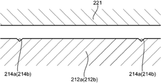
- An output unit 221 that applies ultrasonic vibration toward the outer peripheral surface of the anvil roller 210 is provided at the tip of the horn 220.
- the horn 220 applies ultrasonic vibration to the pre-joining sheet while pressing the output unit 221 against the pre-joining sheet and sandwiching the pre-joining sheet with the anvil roller 210. Accordingly, the sheets 2a and 2b are melted and welded to each other. Further, the elastic member 10 is also melted, and the elastic member 10 and the sheets 2a and 2b are welded to each other. Specifically, the output part 221 sandwiches the pre-joining sheet with the convex part 212, and the sheets 2a and 2b and the elastic member 10 are disposed on the part of the pre-joining sheet disposed on the convex part 212. And the sheets 2a and 2b are joined to each other.
- the tip of the output part 221 has a planar shape (see FIGS. 13 and 14).
- magnesium stearate having a melting point lower than that of the thread rubber 10a is used as the coating layer 10b. Therefore, when the elastic member 10 and the sheets 2a and 2b are welded, the covering layer 10b is melted without melting the thread rubber 10a, and the covering layer 10b and the sheets 2a and 2b are welded.
- the tip 221 of the horn 220 extends in the front-rear direction, and the horn 220 applies ultrasonic vibration to the entire rotation axis direction of the anvil roller 210 with respect to the outer peripheral surface of the anvil roller 210. While the pre-bonding sheet is conveyed by the anvil roller 210, the horn 220 always applies ultrasonic vibration. Therefore, as the pre-bonding sheet is conveyed by the anvil roller 210, the pre-bonding sheet is continuously bonded.
- the sheet 2a is guided by the first guide roller 102 to the outer peripheral surface of the portion P1 of the anvil roller 210 opposite to the horn 220.
- the sheet 2 a is conveyed to the horn 220 side along the outer peripheral surface of the anvil roller 210 as the anvil roller 210 rotates.
- the sheet 2b is introduced by the second guide rollers 104a and 104b into the outer peripheral surface of the portion P2 in the vicinity of the horn 220 of the anvil roller 210 and upstream of the horn 220 in the conveying direction, and then faces the horn 220. Transported to position.
- the elastic member 10 has an outer periphery of the anvil roller 210 at a position P3 between a position P1 where the sheet 2a is introduced into the anvil roller 210 and a position P2 where the sheet 2b is introduced into the anvil roller 210 by the elastic member guide device 110. Introduced to the surface. Thereby, the elastic member 10 is conveyed to the position which opposes the horn 220 in the state arrange
- the position P2 may be any position between the position P3 and the position facing the horn 220, but is preferably close to the position facing the horn 220 and close to the position facing the horn 220. More preferably, it is a position. In this case, the elastic member 10 introduced into the outer peripheral surface of the anvil roller 210 can be prevented from being displaced by being covered with the sheet 2b at an early stage.
- the elastic member 10 is introduced to the outer peripheral surface of the anvil roller 210 in a state of being parallel to each other in the front-rear direction, and on the outer peripheral surface of the anvil roller 210, on the sheet 2a previously introduced to the outer peripheral surface of the anvil roller 210. They are placed parallel to each other in the width direction.
- the elastic member 10 is introduced into the anvil roller 210 in a state where the elastic member 10 is extended in the circumferential direction of the anvil roller 210.
- the elastic member 10 is introduced into the anvil roller 210 in a state where the elastic member 10 is extended to 300% of the natural state (the natural state is 100%).
- the elastic member guide device 110 includes a plurality of elastic member guide rollers 111a, 111b, and 111c and a guide member 112.
- the elastic member guide rollers 111a, 111b, and 111c are rotatable members that can rotate around an axis extending in the front-rear direction, respectively, and guide the elastic member 10 toward the anvil roller 210 in a state where the elastic member 10 is extended by 300% from the natural state.
- the guide member 112 guides the elastic members 10 to the outer peripheral surface of the anvil roller 210 while being separated from each other in the front-rear direction.
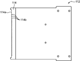
- FIG. 7 is a plan view of the guide member 112.
- FIG. 8 is a side view of the guide member 112.
- the guide member 112 is a flat plate member.
- the guide member 112 has a distal end facing the position P3 on the outer peripheral surface of the anvil roller 210, and a proximal end disposed farther from the anvil roller 210 than the distal end, and extends in a direction in which the guide member 112 contacts and separates from the anvil roller 210. It arrange
- the thickness of the guide member 112 (the vertical dimension shown in FIG. 8) is set small so that the guide member 112 does not interfere with the sheets 2a and 2b, and the guide member 112 has a thin plate shape. is doing.
- An inclined portion 114 that is inclined so as to approach the bottom surface of the guide member 112 toward the tip is formed at the tip of the guide member 112 (portion on the anvil roller 210 side). It has a tapered shape.
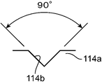
- a plurality of notches 114b are formed in the front-rear direction at the front end 114a of the inclined portion 114, that is, the front end of the guide member 112. These notches 114b are arranged at equal intervals in the front-rear direction. As shown in FIG. 9 which shows a part of the notch 114b in FIG. 7 in an enlarged manner, these notches 114b are recessed from the tip end 114a of the inclined portion 114 toward the base end side, and have a V shape with an opening degree of 90 degrees. Have. These notches 114b reliably position and hold each elastic member 10 in order to guide each elastic member 10 to the outer peripheral surface of the anvil roller 210 in a state of being separated from each other in the front-rear direction. These notches 114b are provided at the same intervals as the grooves 214 so as to face the grooves 214 described later formed in the anvil roller 210, and guide the elastic member 10 to the grooves 214, respectively.
- the guide member 112 is arranged such that an angle ⁇ 1 between the surface of the inclined portion 114 and the tangent line of the anvil roller 210 at the position P3 is 90 degrees or less in a side view. . This is to prevent the elastic member from being detached from each notch 114b.
- the inclined portion 114 is applied to the elastic member 10 by contraction force as shown in FIG.
- the force in the direction opposite to the conveying direction of the elastic member 10 in the inclined portion 114 (the direction toward the proximal end of the guide member 112) can be applied. That is, since the resultant member F10 in the direction of being pushed into the bottom of each notch 114b acts on the elastic member 10, it is possible to suppress the elastic member 10 from being detached from each notch 114b in the inclined portion 114.
- the angle ⁇ 1 between the surface of the inclined portion 114 and the line L1 of the downstream portion of the tangent line of the anvil roller 210 passing through the position P3 in the transport direction of the anvil roller 210 is about 90 degrees.
- the guide member 112 and the sheets 2a and 2b are set at positions that do not interfere with each other.
- the position P3 is set to a position about 10 degrees downstream from the line extending in the horizontal direction passing through the center of the anvil roller 210, and the inclined portion 114 with respect to the bottom surface of the guide member 112.
- the angle ⁇ 2 (see FIG. 8) is set to 10 degrees.
- a convex portion 212 protruding outward in the radial direction is formed on the outer peripheral surface of the anvil roller 210, as shown in FIG. 11, a convex portion 212 protruding outward in the radial direction is formed.
- the convex portion 212 is provided on the outer peripheral surface of the anvil roller 210 over the entire circumferential direction.
- the protrusion 212 has a shape corresponding to the joint 4.
- the joint portion 4 has a rhombus lattice shape
- the convex portion 212 has a rhombus lattice shape corresponding thereto.
- the convex part 212 includes a first convex part 212a for forming the first joint part 4a and a second convex part 212b for forming the second joint part 4b.
- the first convex portions 212a extend along a direction (first direction) intersecting the circumferential direction of the anvil roller 210 (conveying direction of the anvil roller 210), that is, along a line intersecting this circumferential direction, and are parallel to each other. In addition, a plurality of them are arranged at equal intervals in the circumferential direction.
- the second convex portions 212b extend along the circumferential direction of the anvil roller 210 and the direction intersecting the first direction (second direction), that is, along the line intersecting the circumferential direction, and are parallel to each other and the anvil.
- a plurality of rollers 210 are arranged at equal intervals in the circumferential direction of the roller 210.
- Each of the first convex portions 212a and the second convex portions 212b is inclined so as to be symmetric with respect to the front-rear direction at an angle smaller than 45 degrees, and a separation distance between the first convex portions 212a.
- the separation distance between the second protrusions 212b is the same, and the intersection points 212c of the first protrusions 212a and the second protrusions 212b are arranged at equal intervals on a line extending in the front-rear direction and the circumferential direction of the anvil roller 210. It has been.
- FIG. 12 which is a partially enlarged view of FIG. 11, FIG. 13 which is a sectional view taken along line XIII-XIII in FIG. 12, and FIG. 14, which is a sectional view taken along line XIV-XIV in FIG.
- the second convex portion 212b are formed with grooves 214 (214a, 214b) that are recessed inward in the radial direction of the anvil roller 210, respectively.
- a plurality of grooves 214 are formed in the first convex portion 212a and the second convex portion 212b, respectively, at positions separated in the longitudinal direction.
- the portion of the sheet 2a (the sheet disposed on the anvil roller 210 side) where the elastic member 10 is disposed is inserted inside the grooves 214. Therefore, the arrangement of the elastic member 10 with respect to the joint portion 4 and the arrangement of the groove with respect to the convex portion 212 are the same.
- each first convex portion 212a the portion between the intersections 212c with the second convex portion 212b, more specifically, the adjacent intersection 212c.
- Grooves (first grooves) 214a extending in the circumferential direction of the anvil roller 210 are formed in the central portion of each.
- a groove (second groove) 214b is formed in a portion between the intersections 212c with the first convex portion 212a, more specifically, in a central portion of the adjacent intersection 212c. Is formed.
- These grooves 214 are provided at equal intervals on a line extending along the circumferential direction of the anvil roller 210 and at equal intervals on a straight line extending along the front-rear direction.
- the portion of the sheet 2 a where the elastic member 10 is disposed is conveyed by the anvil roller 210 while being inserted into each groove 214.
- the elastic member 10 is guided to each groove 214 by the guide member 112 provided with the notch 114 at a position corresponding to each groove 214, the elastic member 10 is on the sheet 2a. It is stably placed at an appropriate position.
- a part of the elastic member 10 in addition to the sheet 2a is conveyed by the anvil roller 210 in a state of being inserted into the grooves 214. Note that the sheet 2a alone may be conveyed.
- the groove 214 is formed in the portion of the convex portion 212 where the elastic member 10 is disposed, so that when the pre-bonding sheet is clamped during bonding, the elastic member disposed in the pre-bonding sheet At least a part of 10 is in a state of being retracted in this groove. Therefore, it is avoided that the elastic member 10 is cut
- the cross-sectional area of the groove 214 is too large, it may be difficult to appropriately join the elastic member 10 and the sheets 2a and 2b. Therefore, in this embodiment, as shown in FIG. 14, when the elastic member 10 having a natural length is disposed in the groove 214, a part of the elastic member 10 protrudes outward from the groove 214, and the remaining elastic member 10 remains. It is accommodated in the groove 214. Specifically, the shape of the cross section obtained by cutting the groove 214 along a plane orthogonal to the circumferential direction (conveying direction) of the anvil roller 210 is such that the elastic member 10 has a natural length and is disposed in the groove 214.
- a part of the elastic member 10 is set so as to protrude beyond the radial direction of the anvil roller 210 from the linear imaginary line L10 connecting (Q1, Q2).
- the cross-sectional shape of the groove 214 is such that when the elastic member 10 in an extended state of 300% is disposed in the groove 214, the linear imaginary line L10 connecting the opening ends (Q1, Q2) of the groove 214 is used.
- a part of the elastic member 10 is set so as to protrude outward in the radial direction of the anvil roller 210.
- substantially V shape is preferable.
- the sectional area S1 of the groove 214 is preferably smaller than the sectional area of the elastic member 10 to be arranged.
- the method of manufacturing the composite elastic member 1 using the manufacturing apparatus 100 configured as described above includes a guide step and a joining step.
- the sheet 2a is guided to the joining device 200 by the first guide roller 102
- the sheet 2b is guided to the joining device 200 by the second guide rollers 104a and 104b
- the elastic member 10 is guided by the elastic member guiding device 110.
- the elastic members 10 extend between the sheets 2a and 2b in the longitudinal direction of the sheets 2a and 2b and are arranged in parallel with each other. Be transported.
- the sheets 2a and 2b and the elastic member 10 are guided to the outer peripheral surface of the anvil roller 210.
- the guide member 112 guides the portion of the sheet 2 a where the elastic member 10 is disposed and a part of each elastic member 10 to the groove 214 formed in the convex portion 212.
- the horn 220 and the convex portion 212 sandwich the pre-joined sheet, that is, the sheets 2a and 2b in which the elastic member 10 is sandwiched, and impart ultrasonic vibration from the horn 220 toward the convex portion 212 side, thereby elastically
- the member 10 and the sheets 2a and 2b and the sheets 2a and 2b are joined by ultrasonic welding.
- a part of the sheet 2 a on the anvil roller 210 side where the elastic member 10 is disposed and a part of the elastic member 10 are welded while being inserted into the groove 214.
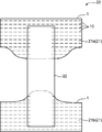
- FIG. 15 is a schematic diagram showing a disposable diaper (wearing article) 20 using the composite elastic member 1 as an example of use of the composite elastic member 1 configured as described above. It is.
- the disposable diaper 20 includes a waist part 21 having a front abdomen 21a disposed on the front side of the wearer's abdomen, a back part 21b disposed on the buttocks side of the wearer, and a crotch part disposed on the crotch of the wearer. 22.
- the composite elastic member 1 of this embodiment is used for the front part 21a and the back part 21b.
- the composite elastic member 1 is applied to the front abdomen 21a and the back part 21b so that the expansion / contraction direction of the composite expansion / contraction member 1 coincides with the waist direction (the left-right direction in FIG. 15) when worn.
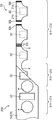
- FIG. 16 is a diagram showing a method for manufacturing the disposable diaper 20.
- This manufacturing method includes stages 1 to 3.
- a pair of continuous bodies 101 in which the composite elastic members 1 are connected in the transport direction are prepared. That is, a continuum 101 for forming the front part 21a and a continuum 101 for forming the back part 21b are prepared.
- the two continuous bodies 101 are transported in the longitudinal direction of the continuous bodies 101 in a state where they are arranged in parallel to each other, and the crotch portion 22 is moved so that the longitudinal direction thereof is orthogonal to the longitudinal direction of the continuous body 101. 101.
- a plurality of crotch parts 22 are placed apart in the transport direction. And the crotch part 22 and the continuous body 101 are joined, and the joined body 102 is formed (joined body formation process).
- stage 2 a hole serving as a leg opening is opened between adjacent crotch parts 22. Thereafter, the joined body 102 is folded in half so that the crotch portion 22 is on the inside with the center line in the width direction (a direction orthogonal to the longitudinal direction of the continuous body 101) as a crease.
- stage 3 the overlapping portion of the continuum 101 that is located in the middle of adjacent crotch parts 22 is joined along the direction perpendicular to the longitudinal direction of continuum 101 to form side seal SS. Together with the (side sealing step), the continuous body 101 is cut along the cutting line K in the side sealing portion (cutting step).
- the waist part 21 (the front abdomen 21a and the back part 21b) is composed of the composite elastic member 1, and the disposable diaper 20 that expands and contracts in the waist direction is manufactured.
- each elastic member 10 of the composite elastic member 1 may be bonded to the two sheets 2a and 2b with a hot melt adhesive in the vicinity of the portion corresponding to the cutting line K. In this way, it is possible to prevent the elastic members 10 from coming off due to cutting along the cutting line K.
- the two sheets 2 a and 2 b extend along the stretch direction of the composite stretchable member 1 and a line intersecting the plurality of elastic members 10.
- the two sheets 2a and 2b are joined to each other, and a plurality of elastic members 10 that are sandwiched between the sheets 2a and 2b and extend along the stretching direction of the composite stretchable member 1 intersect with the joints 4 respectively.
- they are joined to the sheets 2a and 2b, respectively.
- each sheet 2a, 2b is continuously joined along the line extending in the stretching direction of the composite stretchable member 1 and intersecting the longitudinal direction of the sheets 2a, 2b at each joint 4 and each elastic member. 10 and the sheets 2a and 2b are joined at the joint 4 respectively.
- the bonding force between the sheets 2a, 2b and between the sheets 2a, 2b and the elastic member 10 can be increased, and the sheets 2a, 2b or the sheets 2a, 2b and the elastic member 10 are peeled off during use. Can be suppressed.
- the waist part 22 is prevented from being damaged at the time of detachment or the like while ensuring the stretchability of the waist part 22 and improving the comfort. can do.
- Each of the joint portions 4 includes a plurality of first joint portions 4a extending in parallel with each other along a direction intersecting the longitudinal direction of the sheets 2a and 2b (stretching direction of the composite stretchable member 1), and the sheets 2a and 2b.
- a plurality of second joints 4b that extend in parallel with each other along the direction intersecting the longitudinal direction and intersect with each first joint 4a.
- the sheets 2a and 2b are joined to each other at joints 4a and 4b extending in different directions. Therefore, even when force is applied to the composite elastic member 1 from various directions, the sheets 2a and 2b or the sheets 2a and 2b and the elastic member 10 can be more reliably prevented from being peeled off. it can. Further, since the first joint portion 4a and the second joint portion 4b intersect each other, the joining force of the composite stretchable member 1 at each position of the intersection 4c, and hence the sheets 2a and 2b at positions close to the intersection 4c. The joining force of can be increased.
- the longitudinal direction (first direction) of the first joint 4a and the longitudinal direction (second direction) of the second joint 4b are respectively the longitudinal directions of the sheets 2a and 2b (stretching direction of the composite stretchable member 1). ) In a direction intersecting with a direction orthogonal to.
- first joint portion 4a and the second joint portion 4b are inclined at an angle smaller than 45 degrees with respect to the width direction of the sheets 2a and 2b (direction perpendicular to the stretch direction of the composite stretch member 1), respectively. is doing.
- the elastic member 10 in the longitudinal direction of the sheets 2a, 2b (the expansion / contraction direction of the composite expansion / contraction member 1), the respective joint portions 4a, 4b, the intersections 4d, 4e, that is, the joint points 4d between the elastic member 10 and the respective sheets 2a, 2b,
- the distance 4e (the distance between the adjacent joint points 4d and 4e) can be shortened. Therefore, wrinkles generated between the joining points 4d and 4e in the longitudinal direction of the sheets 2a and 2b (stretching direction of the composite stretchable member 1) in a state where the composite stretchable member 1 is not stretched can be made finer. . Therefore, the touch can be improved.
- Intersections 4c between the first joints 4a and the second joints 4b are arranged on a straight line extending in the longitudinal direction of the sheets 2a, 2b (stretching direction of the composite stretchable member 1), and the sheets 2a, 2b They are arranged on a straight line extending in the width direction (direction orthogonal to the expansion / contraction direction of the composite elastic member 1).
- intersections 4c of the joint portions 4a and 4b can be arranged in an orderly manner, and the pattern due to wrinkles generated between these intersections 4c becomes regular, so that the appearance can be improved and the sheets 2a and 2b
- the joining force between the sheets 2a and 2b in the longitudinal direction (stretching direction of the composite stretchable member 1) and the width direction can be increased.
- the elastic members 10 may intersect at the intersections 4c between the first joints 4a and the second joints 4b, but at the portions other than the intersections 4c, the first joints 4a and the second joints. You may cross 4b.
- the elastic member 10 is individually joined to the sheet by the first joint 4a and the second joint 4b. Therefore, the number of joint points between the elastic member 10 and the sheets 2a and 2b can be increased as compared with the case where the elastic member 10 and the joint portions 4a and 4b intersect at the intersection 4c. Therefore, the bonding force between the elastic member 10 and the sheets 2a and 2b can be increased.
- a first elastic member side intersection 4d which is an intersection between each elastic member 10 and each first joint 4a
- a second elastic member side intersection 4e which is an intersection between each elastic member 10 and each second joint 4b.
- the sheets 2a and 2b are arranged on a straight line extending in the width direction (direction orthogonal to the expansion / contraction direction of the composite expansion / contraction member 1).
- the joining point between the elastic member 10 and the sheets 2a and 2b that is, the ridge formed between the elastic member side intersections 4d and 4e may be formed so as to be aligned on a straight line extending in the width direction of the sheets 2a and 2b. Therefore, the appearance can be improved. Moreover, the touch about this direction can be made favorable.
- Intersections between the elastic members 10 and the joint portions 4, that is, joints between the elastic members 10 and the sheets 2a and 2b, are arranged at equal intervals in the longitudinal direction of the sheets 2a and 2b (stretching direction of the composite elastic member 1). . That is, each elastic member 10 and the joint portion 4 intersect at equal intervals in the longitudinal direction of the sheets 2a and 2b.
- the size of the ridge formed between the joining points 4d and 4e between the elastic member 10 and the sheets 2a and 2b specifically, the dimension in which the ridge projects in the direction perpendicular to the outside, that is, the sheets 2a and 2b.
- the sheet 2a, 2b can be made uniform in the longitudinal direction (stretching direction of the composite stretchable member 1). Therefore, the appearance and the touch can be improved.
- Each elastic member 10 includes a plurality of elastic bodies 10a and a covering layer 10b covering them, and the covering layer 10b is welded to the sheets 2a and 2b so that each elastic member 10 and each sheet 2a and 2b Are joined.
- first joint 4a and the second joint 4b may be omitted.
- the joint portion 4 may be formed so as to extend in a direction orthogonal to the longitudinal direction of the sheets 2a and 2b.
- the joint portion 504 may extend along the width direction of the sheets 2a and 2b (the direction orthogonal to the expansion / contraction direction of the composite expansion / contraction member 501).
- the bonding force between the sheets 2a and 2b can be increased in the width direction of the sheets 2a and 2b (the direction orthogonal to the expansion and contraction direction of the composite elastic member 501).
- the joint portion 504 in order to make the joint portion 504 have the pattern shown in FIG. 17, it is necessary to provide a plurality of convex portions parallel to each other with respect to the conveyance direction of the anvil roller 210.
- the output unit 221 is intermittently contacted. Therefore, there is a possibility that large vibration and noise are generated.
- an auxiliary seal 509 is provided at the end in the width direction of the sheets 2a and 2b as shown in FIG. preferable.
- the width direction of the outer peripheral surface of the anvil roller 210 (specifically, the convex portion corresponding to the joint portion 504) is separated from the convex portion 504 that joins the sheets 2a and 2b while sandwiching the elastic member 10.
- An auxiliary convex portion 509 (specifically, a convex portion corresponding to the auxiliary seal 509) for joining only the sheets 2a and 2b is provided at an end portion in a direction parallel to the rotation axis of the anvil roller 210. Further, these auxiliary convex portions 509 are provided so as to be between adjacent convex portions 504 in the conveying direction of the anvil roller 210.
- a plurality of (five in the example of FIG. 18) auxiliary convex portions 509 that are separated from each other in the width direction of the anvil roller 210 are provided in a row and are adjacent to each other in the conveyance direction of the anvil roller 210. Three rows are provided between the convex portions 504.
- the convex part including the convex part 504 and the auxiliary convex part 509 and the output part 221 of the horn 220 can be contacted more continuously. Therefore, noise and vibration generated when the convex portion and the output portion 221 of the horn 220 start abutting can be reduced.
- FIG. In this way, the convex portion and the output portion 221 of the horn 220 can be continuously brought into contact with each other more reliably.
- the auxiliary convex portion 509 has a relatively short dimension in the width direction of the anvil roller 210. Therefore, when the auxiliary convex portion 509 and the output portion 221 of the horn 220 are in contact with each other, a relatively large pressure is applied to the sheets 2a and 2b sandwiched therebetween, and the sheets 2a and 2b are easily damaged.
- the auxiliary convex portion 519 when the auxiliary convex portion 519 is provided so as to be continuous along the conveyance direction of the anvil roller 210, the sheets 2a, 2b are damaged along the auxiliary convex portion 509, and the sheets 2a, 2b, There is a possibility that 2b is separated into a side where it comes into contact with the auxiliary convex part 509 and another part. Therefore, when there is a possibility that the sheets 2a and 2b may be damaged, it is preferable to intermittently provide the auxiliary convex portions 509 as shown in FIG.
- the portion of the sheets 2a and 2b where the auxiliary seal portion 509 is formed may be cut out after passing through the anvil roller 210, or may be bent and used as a part of the composite elastic member 501. Also good.
- the sheet 2a, 2b (expandable member 601) has a cross pattern area A1 in which a joint portion is composed of the first joint portion 4a and the second joint portion 4b, and a joint portion.
- the straight pattern region A2 configured by the joint (third joint) 504 along the width direction of the sheets 2a and 2b shown in FIG. 17 is formed, and the intersection of the first joint 4a and the second joint 4b
- the joint portion 504 may extend along the width direction. In this way, the bonding force between the sheets 2a and 2b along the width direction in the straight pattern region A2 while further increasing the bonding force between the sheets 2a and 2b along the direction intersecting the width direction in the intersecting pattern region A1. Can be increased.
- these sheets 2a and 2b are applied to the waistline part of wearing articles, such as the said disposable diaper 20, and the straight pattern area
- region A2 is on the edge side of a waistline part, and the junction part 504 is toward an edge part from the inner side of a waistline part.
- the crease formed in the cross pattern area A1 improves the appearance and the touch
- the crease formed in the straight pattern area A2 forms an open space facing outward from the edge of the waistline portion.
- the air permeability can be improved.
- a passage that connects the inside and the outside of the waistline portion is formed between the joint portions 504, so that air permeability can be improved.
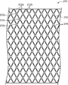
- stretchable member 701 may be configured as shown in FIG.
- a joint portion 704 is provided that extends along a line extending in the width direction of the sheets 2a and 2b while being bent a plurality of times toward one side and the other side in the longitudinal direction.
- the joint portions 704 are arranged between the first unit joint portions 704 arranged in parallel with each other in the longitudinal direction of the sheets 2 a and 2 b and the adjacent first unit joint portions 704.
- the second unit joint portion 705 is located between the second unit joint portions 705 arranged in parallel with each other in the longitudinal direction of the sheets 2a and 2b.
- a portion 704a inclined obliquely downward to the right and a portion 704b inclined obliquely downward to the left from the lower end of the portion 704a are alternately continuous in the vertical direction (sheet 2a, 2b in the width direction).
- the second unit joint portion 705 has a shape symmetrical to the first zigzag joint portion 704 with reference to a line extending in the vertical direction in FIG. 20 (a line extending in the width direction of the sheets 2a and 2b).
- a portion 705a inclined obliquely to the left and opposite to the portion 704a obliquely inclined downward to the right of the first unit joint portion 704, and a portion 705b inclined obliquely downward to the right from the lower end of the portion 705a are continuous.
- the shape extends.
- the elastic members 10 extend in the longitudinal direction of the sheets 2a and 2b through the central portions in the width direction of the sheets 2a and 2b of the portions 704a, 704b, 705a and 705b.
- first unit joint portion 704 and the second unit joint portion 705 merge at the boundary portion between the region B1 and the straight pattern region A2, and the joint portion 504 constituting the straight pattern from the merged portion is the sheet 2a. , 2b extends straight along the width direction.
- the joint portion 705 When the joint portion 705 is configured in this way, the proportion of the joint portion per unit area in the region B1 can be reduced compared to the case shown in FIG. Specifically, in the example shown in FIG. 19, since the first joint 4a and the second joint 4b intersect, the ratio of the area of the joint 4 (4c) per unit area near these intersections is growing. As a result, the composite elastic member 601 becomes hard in the vicinity of this intersection. On the other hand, in the example shown in FIG. 20, since the unit joint portions 704 and 705 do not intersect (excluding the boundary portion between the region B1 and the straight pattern region A2), the area (unit) of the joint portion 4 to be formed. It is possible to suppress the composite stretchable member 601 from becoming hard by suppressing an increase in the area ratio of the bonded portion per area), and it is possible to improve the touch of this.
- each elastic member 10 may be different.
- each elastic member 10 only needs to be along the longitudinal direction of the sheets 2a and 2b (the expansion / contraction direction of the composite elastic member 1), and may extend in a direction intersecting with each other instead of being parallel to each other. You may extend in the direction meandering periodically.
- first joint portion 4a and the second joint portion 4b may be formed so as to extend in the width direction of the sheets 2a and 2b.
- first joint portion 4a and the second joint portion 4b is at an angle of 45 degrees or more with respect to the width direction of the sheets 2a and 2b (direction perpendicular to the stretch direction of the composite stretch member 1). It may be inclined with.
- intersection 4c of each 1st junction part 4a and each 2nd junction part 4b does not need to be located on the straight line extended in the width direction of sheet
- first intersection 4d and the second intersection 4e may not be arranged on a straight line extending in the longitudinal direction of the sheets 2a and 2b, and the positions of these intersections 4d and 4e are arranged in the width direction of the sheets 2a and 2b. You may shift mutually.
- each elastic member 10 is disposed so as to pass through the intersection (joint portion side intersection 4c) between each first joint portion 4a and each second joint portion 4b, and is joined to the sheets 2a and 2b at this portion. Also good.
- intersection 4d of each elastic member 10 and each 1st junction part 4a and the intersection 4e of each elastic member 10 and each 2nd junction part 4b are arranged on the straight line extended in the width direction of sheet
- intersections 4d and 4e between the elastic members 10 and the joints 4 may be arranged at unequal intervals in the longitudinal direction of the sheets 2a and 2b.
- the joint structure between the elastic member 10 and the sheets 2a and 2b is not limited to the above. That is, the rubber thread 10a and the sheets 2a and 2b of the elastic member 10 may be joined.
- the elastic member 10 may be composed of a plurality of thread rubbers 10 a gathered in a bundle, and the sheets 2 a and 2 b may be welded to at least one thread rubber 10 a located on the outer peripheral surface of the elastic member 10. Even in this case, since the sheets 2a and 2b are welded to the thread rubber 10a located on the peripheral surface of the elastic member 10, it is possible to suppress damage to other thread rubber 10a that is not joined.
- the elastic member 10 using silicon oil or the like having a low boiling point is used as the covering layer 10b, and when the elastic member 10 and the sheets 2a and 2b are welded, the covering layer 10b is evaporated and a part of the thread rubber 10a and the sheet 2a , 2b may be joined directly. In this case, part of the thread rubber 10a and at least one of the sheets 2a and 2b may be melted and joined together, or the thread rubber 10a having adhesive strength is used, and the thread rubber 10a is obtained by this adhesive strength. And the sheets 2a and 2b may be joined.
- the manufacturing method of the disposable diaper 20 using the composite elastic member 1 is not restricted to the above.
- one continuous body 201 in which the composite elastic members 1 are connected in the transport direction is prepared on the stage 1, and the continuous body 201 is transported in the longitudinal direction.
- the plurality of crotch parts 22 are arranged at the center in the width direction of the continuous body 201 so that the longitudinal direction of the crotch part 22 is orthogonal to the longitudinal direction of the continuous body 201.
- the crotch part 22 and the continuous body 201 are joined, and the joined body 202 is formed (joined body formation process).
- a hole X serving as a leg opening for inserting a wearer's leg through the continuous body 201 is formed in advance, and then the crotch portion 22 is joined. The opening of the hole X may be performed after the crotch part 22 is joined to the continuous body 101.
- the joined body 202 is folded in half so that the crotch portion 22 is on the inner side with the center line in the width direction (direction perpendicular to the longitudinal direction of the continuous body) as the crease.
- stage 3 The procedure of the stage 3 is the same as that of the above embodiment, and in the stage 3, the overlapping portions of the continuous body 201 in the portion located in the middle of the crotch portions 22 adjacent to each other in the longitudinal direction of the continuous body 201 are orthogonal to the longitudinal direction. Are joined along the side seal SS to form the side seal SS (side seal step), and the continuous body 201 is cut along the cutting line K in the side seal portion (cutting step).
- the apparatus since it is not necessary to prepare a continuous body of a plurality of composite elastic members 1 and to transport them, the apparatus can be simplified.
- the formation of the hole serving as the leg opening can be omitted.
- the present invention is a composite elastic member that can be expanded and contracted in a specific direction, and two sheets facing each other and along the specific direction so as to be expandable and contractable in the specific direction between the sheets.
- a plurality of elastic members extending, and each of the sheets is bonded to each other at a plurality of bonding portions, and each of the bonding portions extends continuously along a line intersecting the specific direction, respectively.
- a composite elastic member characterized in that it intersects with an elastic member, and each elastic member is joined to each sheet at an intersection with each joint.
- each sheet is continuously joined along a line intersecting with a specific direction (stretching direction of the composite stretchable member) at each joining portion, thereby increasing the joining force between the sheets. be able to. Therefore, it is possible to prevent the sheets from being peeled off during use.
- each joint portion continuously intersects with a plurality of elastic members, and the elastic member is joined to the sheet at this intersection, each joint portion is provided intermittently and these joint portions are part of the elastic member. As compared with the case where only the crossing points, it is possible to secure many joints between the elastic member and the sheet, and it is possible to increase the bonding force between the elastic member and the sheet.
- the said structure WHEREIN is a 2nd direction which cross
- the sheets are joined to each other at joints extending in different directions, even when a force is applied to the composite elastic member from various directions, the sheets or the sheet and the elastic member It is possible to more reliably suppress peeling. Moreover, since the 1st junction part and the 2nd junction part cross
- the first direction and the second direction are directions intersecting with a direction orthogonal to the specific direction.
- the first direction and the second direction are inclined at an angle smaller than 45 degrees with respect to a direction orthogonal to the specific direction.
- intersections of the first joints and the second joints are arranged on a straight line extending in the specific direction, and are arranged on a straight line extending in a direction orthogonal to the specific direction. Is preferred.
- intersections of the joints can be arranged in an orderly manner. Therefore, it is possible to improve the appearance by regularizing the pattern caused by the wrinkles generated between the intersections of the joints, and to increase the joining force between the sheets in the specific direction and the direction orthogonal thereto.
- each elastic member intersects with the first joint and the second joint at a portion excluding an intersection between the first joint and the second joint.
- the said structure WHEREIN The 1st elastic member side intersection which is an intersection of each said elastic member and each said 1st junction part, and the 2nd elastic member side intersection which is an intersection of each said elastic member and each said 2nd junction part Are preferably arranged on a straight line extending in a direction orthogonal to the specific direction.
- the wrinkles formed between the joining points of the elastic member and the sheet are arranged on a straight line extending in a direction orthogonal to the specific direction. Therefore, the appearance can be improved.
- the intersections of the first joints and the second joints are arranged on a straight line extending in the specific direction and are arranged on a straight line extending in a direction orthogonal to the specific direction.
- the elastic members intersect with the first joint and the second joint at portions other than the intersections between the first joint and the second joint, and the joint and the specific part. It is preferable to cross at equal intervals in the direction.
- the size of the crease formed between the joining points of the elastic member and the sheet (projecting dimension to the outside of the heel) while increasing the joining force between the sheets and the joining force between the elastic member and the sheet. ) Can be made uniform in a specific direction to improve the appearance and feel.
- each sheet includes the cross pattern region in which the joint portion includes the plurality of first joint portions and the plurality of second joint portions, and the joint adjacent to the cross pattern region. It is preferable that the portion includes a straight pattern region including a third joint portion extending in a direction orthogonal to the specific direction from an intersection of each first joint portion and each second joint portion.
- each of the joints may extend along a direction orthogonal to the specific direction.
- each of the elastic members includes a plurality of fibrous elastic bodies gathered in a bundle, and at least some of the peripheral surfaces of the plurality of fibrous elastic bodies are covered with a coating layer,
- the elastic members and the sheets are preferably joined by welding the covering layer to the sheets.
- the elastic member is composed of a plurality of fibrous elastic bodies gathered in a bundle shape, and each elastic member and each sheet is at least one located on the peripheral surface of the elastic member.
- the sheet may be bonded to the fibrous elastic body by welding.
- the present invention is a wearing article having a waistline portion arranged around the wearer's waistline, characterized in that at least a part of the waistline portion is formed by the composite elastic member configured as described above.
- An article to be worn is provided.
- the composite stretchable member according to the present invention can increase the bonding force between sheets and between the elastic member and the sheet as described above. Therefore, by using this composite stretchable member for at least a part of the waistline part of the worn article, it is possible to prevent damage such as the elastic member coming off at the waistline part at the time of detachment while ensuring stretchability and improving comfort. can do.
- the present invention is a method of manufacturing a worn article having a waistline portion arranged around the wearer's waist and a crotch portion arranged at the wearer's inseam, the composite stretchable member configured as described above
- the continuous body is prepared in such a way that the continuous body is transported in the longitudinal direction to form the waistline portion, and the continuous body is formed so that the longitudinal direction is perpendicular to the longitudinal direction of the continuous body.
- the waistline portion can be formed using the composite elastic member having a high bonding force as described above.
- the joined article formed by joining the crotch part and the continuous body of the composite elastic member is folded in two, a side seal is formed on the joined body, and the joined article is cut, thereby cutting the worn article. Can be manufactured.
- the manufacturing method according to the present invention it is possible to manufacture a worn article that has high bonding strength at the waistline portion and that is prevented from being damaged such as the elastic member coming off at the time of desorption.
- the joined body forming step prepares a pair of continuous bodies of the composite elastic members, conveys the both continuous bodies in parallel to each other, and joins the crotch portion across the continuous bodies. It is preferable to include a step of forming the joined body.
Landscapes
- Engineering & Computer Science (AREA)
- Health & Medical Sciences (AREA)
- Mechanical Engineering (AREA)
- Life Sciences & Earth Sciences (AREA)
- Epidemiology (AREA)
- Biomedical Technology (AREA)
- Heart & Thoracic Surgery (AREA)
- Vascular Medicine (AREA)
- Animal Behavior & Ethology (AREA)
- General Health & Medical Sciences (AREA)
- Public Health (AREA)
- Veterinary Medicine (AREA)
- Manufacturing & Machinery (AREA)
- Textile Engineering (AREA)
- Botany (AREA)
- Absorbent Articles And Supports Therefor (AREA)
- Laminated Bodies (AREA)
Abstract
Description
図1は、本発明の実施形態に係る複合伸縮部材の平面図である。図2は、図1のII-II線断面図の一部である。 (1) Configuration of Composite Elastic Member FIG. 1 is a plan view of a composite elastic member according to an embodiment of the present invention. FIG. 2 is a part of a cross-sectional view taken along line II-II in FIG.
次に、前記複合伸縮部材1を製造するための製造装置について説明する。 (2) Manufacturing apparatus for composite elastic member Next, a manufacturing apparatus for manufacturing the composite
前記のように構成された製造装置100を用いて複合伸縮部材1を製造する方法は、案内工程と接合工程とを含む。 (3) Manufacturing method The method of manufacturing the composite
図15は、前記のように構成された複合伸縮部材1の使用例として、この複合伸縮部材1が用いられた使い捨ておむつ(着用物品)20を示した概略図である。 (4) Wearing article and manufacturing method thereof FIG. 15 is a schematic diagram showing a disposable diaper (wearing article) 20 using the composite
Claims (15)
- 特定方向に伸縮可能な複合伸縮部材であって、
互いに対向する2枚のシートと、
前記各シートの間で前記特定方向に伸縮可能となるように当該特定方向に沿って延びる複数の弾性部材とを備え、
前記各シートは、複数の接合部で互いに接合されており、
前記各接合部は、それぞれ前記特定方向と交差する線に沿って連続的に延びて複数の前記弾性部材と交差しており、
前記各弾性部材は、前記各接合部との交差点においてそれぞれ前記各シートに接合されていることを特徴とする複合伸縮部材。 A composite elastic member that can expand and contract in a specific direction,
Two sheets facing each other;
A plurality of elastic members extending along the specific direction so as to be expandable and contractible in the specific direction between the sheets;
Each of the sheets is bonded to each other at a plurality of bonding portions,
Each of the joints extends continuously along a line that intersects the specific direction and intersects the plurality of elastic members,
Each elastic member is joined to each sheet at an intersection with each joint, respectively. - 請求項1に記載の複合伸縮部材であって、
前記接合部は、前記特定方向と交差する第1の方向に沿って互いに平行に延びる複数の第1接合部と、前記特定方向および前記第1の方向と交差する第2の方向に沿って互いに平行に延びるとともに少なくとも1の前記第1接合部とそれぞれ交差する複数の第2接合部とを含むことを特徴とする複合伸縮部材。 The composite elastic member according to claim 1,
The joint portion includes a plurality of first joint portions extending in parallel with each other along a first direction intersecting with the specific direction, and a second direction intersecting with the specific direction and the first direction. A composite elastic member comprising a plurality of second joints extending in parallel and intersecting at least one of the first joints. - 請求項2に記載の複合伸縮部材であって、
前記第1の方向と第2の方向とは、それぞれ前記特定方向と直交する方向に対して交差する方向であることを特徴とする複合伸縮部材。 The composite elastic member according to claim 2,
The composite elastic member, wherein the first direction and the second direction are directions intersecting with a direction orthogonal to the specific direction. - 請求項3に記載の複合伸縮部材であって、
前記第1の方向と前記第2の方向とは、それぞれ、前記特定方向と直交する方向に対して、45度よりも小さい角度で傾斜していることを特徴とする複合伸縮部材。 The composite elastic member according to claim 3,
The composite elastic member, wherein the first direction and the second direction are inclined at an angle smaller than 45 degrees with respect to a direction orthogonal to the specific direction. - 請求項3または4に記載の複合伸縮部材であって、
前記各第1接合部と前記各第2接合部との交差点は、前記特定方向に延びる直線上に並んでいるとともに、当該特定方向と直交する方向に延びる直線上に並んでいることを特徴とする複合伸縮部材。 The composite elastic member according to claim 3 or 4,
The intersections of the first joints and the second joints are arranged on a straight line extending in the specific direction and are arranged on a straight line extending in a direction orthogonal to the specific direction. A composite elastic member. - 請求項2~5のいずれかに記載の複合伸縮部材であって、
前記各弾性部材は、前記各第1接合部と前記各第2接合部との交差点を除く部分で、これら第1接合部および第2接合部と交差していることを特徴とする複合伸縮部材。 The composite elastic member according to any one of claims 2 to 5,
Each elastic member is a portion excluding an intersection between each first joint and each second joint, and intersects with the first joint and the second joint. . - 請求項2~6のいずれかに記載の複合伸縮部材であって、
前記各弾性部材と前記各第1接合部との交差点である第1弾性部材側交差点と、前記各弾性部材と前記各第2接合部との交差点である第2弾性部材側交差点とは、前記特定方向と直交する方向に延びる直線上に並んでいることを特徴とする複合伸縮部材。 The composite elastic member according to any one of claims 2 to 6,
The first elastic member side intersection that is an intersection between each elastic member and each first joint, and the second elastic member side intersection that is an intersection between each elastic member and each second joint are A composite elastic member characterized by being arranged on a straight line extending in a direction orthogonal to a specific direction. - 請求項5に記載の複合伸縮部材であって、
前記各弾性部材は、前記各第1接合部と前記各第2接合部との交差点を除く部分でこれら第1接合部および第2接合部と交差しているとともに、これら接合部と前記特定方向について等間隔に交差していることを特徴とする複合伸縮部材。 The composite elastic member according to claim 5,
Each of the elastic members intersects with the first joint and the second joint at a portion excluding the intersection between the first joint and the second joint, and the joint and the specific direction. A composite elastic member characterized by crossing at equal intervals. - 請求項2~8のいずれかに記載の複合伸縮部材であって、
前記各シートは、前記接合部が複数の前記第1接合部と複数の前記第2接合部とで構成される交差パターン領域と、当該交差パターン領域に隣接して前記接合部が前記各第1接合部と前記各第2接合部との交差点から前記特定方向と直交する方向に延びる第3接合部で構成されるストレートパターン領域とを含むことを特徴とする複合伸縮部材。 The composite elastic member according to any one of claims 2 to 8,
Each of the sheets has a cross pattern region in which the joint portion includes a plurality of the first joint portions and a plurality of the second joint portions, and the joint portion is adjacent to the cross pattern region and the first joint portion A composite elastic member, comprising: a straight pattern region constituted by a third joint portion extending in a direction orthogonal to the specific direction from an intersection between the joint portion and each of the second joint portions. - 請求項1に記載の複合伸縮部材であって、
前記各接合部は、それぞれ前記特定方向と直交する方向に沿って延びていることを特徴とする複合伸縮部材。 The composite elastic member according to claim 1,
Each of the joint portions extends along a direction orthogonal to the specific direction. - 請求項1~10のいずれかに記載の複合伸縮部材であって、
前記弾性部材は、束状に集合した複数の繊維状弾性体を含み、
複数の前記繊維状弾性体の少なくとも一部の周面は、被覆層により被覆されており、
前記各弾性部材と前記各シートとは、前記被覆層が前記シートに溶着することで接合されていることを特徴とする複合伸縮部材。 The composite elastic member according to any one of claims 1 to 10,
The elastic member includes a plurality of fibrous elastic bodies assembled in a bundle,
At least some peripheral surfaces of the plurality of fibrous elastic bodies are covered with a coating layer,
Each elastic member and each sheet are joined together by welding the covering layer to the sheet. - 請求項1~10のいずれかに記載の複合伸縮部材であって、
前記弾性部材は、束状に集合した複数の繊維状弾性体からなり、
前記各弾性部材と前記各シートとは、前記弾性部材の周面に位置する少なくとも1の前記繊維状弾性体に前記シートが溶着することで接合されていることを特徴とする複合伸縮部材。 The composite elastic member according to any one of claims 1 to 10,
The elastic member is composed of a plurality of fibrous elastic bodies assembled in a bundle shape,
Each elastic member and each sheet are joined together by welding the sheet to at least one fibrous elastic body located on the peripheral surface of the elastic member. - 着用者の胴回りに配置される胴回り部を有する着用物品であって、
胴回り部の少なくとも一部が、請求項1~12のいずれかに記載の複合伸縮部材により形成されたことを特徴とする着用物品。 A wearing article having a waistline portion arranged around a wearer's waistline,
A wearing article, wherein at least a part of the waistline portion is formed of the composite elastic member according to any one of claims 1 to 12. - 着用者の胴回りに配置される胴回り部と着用者の股下に配置される股下部とを有する着用物品を製造する方法であって、
請求項1~12の何れか1項に記載の複合伸縮部材の連続体を用意して、前記胴回り部を形成するために前記連続体をその長手方向に搬送するとともに、前記股下部をその長手方向が前記連続体の長手方向に直交するように当該連続体に接合して接合体を形成する接合体形成工程と、
前記接合体を前記連続体の長手方向と直交する幅方向の中心線を折り目として二つ折りにする二つ折り工程と、
前記連続体の長手方向について隣接する前記股下部の中間に位置する部分における前記連続体の重なり部分同士を当該連続体の長手方向に直交する方向に沿って接合してサイドシールを形成するサイドシール工程と、
前記連続体を前記サイドシールにおける切断線に沿って切断する切断工程と、を含む着用物品の製造方法。 A method for producing a worn article having a waistline portion disposed around a wearer's waist and a crotch portion disposed at a crotch of the wearer,
A continuous body of the composite elastic member according to any one of claims 1 to 12 is prepared, and the continuous body is transported in the longitudinal direction to form the waistline portion, and the crotch portion is A joined body forming step of joining the continuous body to form a joined body so that the direction is orthogonal to the longitudinal direction of the continuous body;
Folding step in which the joined body is folded in half with a center line in the width direction perpendicular to the longitudinal direction of the continuous body as a fold;
A side seal that forms a side seal by joining overlapping portions of the continuous bodies in a portion located in the middle of the crotch portion adjacent to each other in the longitudinal direction of the continuous body along a direction perpendicular to the longitudinal direction of the continuous body Process,
A cutting step of cutting the continuous body along a cutting line in the side seal. - 請求項14に記載の着用物品の製造方法であって、
前記接合体形成工程は、前記複合伸縮部材の連続体を一対用意して該両連続体を互いに平行に搬送するとともに、前記股下部を前記両連続体に跨って接合して前記接合体を形成する工程を含むことを特徴とする着用物品の製造方法。 It is a manufacturing method of the wearing article according to claim 14,
In the joined body forming step, a pair of continuous bodies of the composite stretchable members are prepared, the two continuous bodies are transported in parallel with each other, and the crotch portion is joined across the continuous bodies to form the joined body. The manufacturing method of the wearing article characterized by including the process to do.
Priority Applications (4)
| Application Number | Priority Date | Filing Date | Title |
|---|---|---|---|
| JP2017524870A JP6625126B2 (en) | 2015-06-22 | 2016-06-17 | Composite elastic member, wearing article, and method of manufacturing wearing article |
| CN201680035386.7A CN107848244B (en) | 2015-06-22 | 2016-06-17 | Composite stretch member, wearing article, and method for manufacturing wearing article |
| US15/736,103 US10596045B2 (en) | 2015-06-22 | 2016-06-17 | Composite stretchable member, wearable article, and method for producing wearable article |
| EP16814284.2A EP3296100B1 (en) | 2015-06-22 | 2016-06-17 | Composite stretchable member, wearable article, and method for producing wearable article |
Applications Claiming Priority (2)
| Application Number | Priority Date | Filing Date | Title |
|---|---|---|---|
| JP2015124927 | 2015-06-22 | ||
| JP2015-124927 | 2015-06-22 |
Publications (1)
| Publication Number | Publication Date |
|---|---|
| WO2016208513A1 true WO2016208513A1 (en) | 2016-12-29 |
Family
ID=57585636
Family Applications (1)
| Application Number | Title | Priority Date | Filing Date |
|---|---|---|---|
| PCT/JP2016/068158 WO2016208513A1 (en) | 2015-06-22 | 2016-06-17 | Composite stretching/contracting member, wearable article, and method for producing wearable article |
Country Status (5)
| Country | Link |
|---|---|
| US (1) | US10596045B2 (en) |
| EP (1) | EP3296100B1 (en) |
| JP (1) | JP6625126B2 (en) |
| CN (1) | CN107848244B (en) |
| WO (1) | WO2016208513A1 (en) |
Cited By (20)
| Publication number | Priority date | Publication date | Assignee | Title |
|---|---|---|---|---|
| JP2019017950A (en) * | 2017-07-21 | 2019-02-07 | 王子ホールディングス株式会社 | Composite stretchable member |
| WO2019148156A1 (en) * | 2018-01-29 | 2019-08-01 | Curt G. Joa, Inc. | Apparatus and method of manufacturing an elastic composite structure for an absorbent sanitary product |
| CN110325156A (en) * | 2017-02-23 | 2019-10-11 | 尤妮佳股份有限公司 | Manufacturing method, manufacturing device and the absorbent commodity of absorbent commodity |
| JP2019183343A (en) * | 2018-04-13 | 2019-10-24 | 花王株式会社 | Method of manufacturing sheet-like mask |
| JP2019183341A (en) * | 2018-04-13 | 2019-10-24 | 花王株式会社 | Production method of sheet-state mask |
| WO2020235495A1 (en) | 2019-05-22 | 2020-11-26 | 株式会社瑞光 | Composite stretchable member and wearable article using same |
| WO2021020118A1 (en) | 2019-07-26 | 2021-02-04 | 株式会社瑞光 | Method for manufacturing underpants-type wearable article |
| EP3646830A4 (en) * | 2017-06-29 | 2021-03-24 | Zuiko Corporation | Device and method for producing stretchable laminate for wearable article |
| US10966873B2 (en) | 2016-12-20 | 2021-04-06 | The Procter & Gamble Company | Methods and apparatuses for making elastomeric laminates with elastic strands unwound from spools on surface unwinders |
| WO2021140831A1 (en) | 2020-01-10 | 2021-07-15 | 株式会社瑞光 | Method for manufacturing disposable wearing article |
| US11129753B2 (en) | 2017-09-01 | 2021-09-28 | The Procter & Gamble Company | Methods and apparatuses for making elastomeric laminates |
| US11147718B2 (en) | 2017-09-01 | 2021-10-19 | The Procter & Gamble Company | Beamed elastomeric laminate structure, fit, and texture |
| US11173072B2 (en) | 2019-09-05 | 2021-11-16 | Curt G. Joa, Inc. | Curved elastic with entrapment |
| US11547613B2 (en) | 2017-12-05 | 2023-01-10 | The Procter & Gamble Company | Stretch laminate with beamed elastics and formed nonwoven layer |
| US11648154B2 (en) | 2019-05-31 | 2023-05-16 | Zuiko Corporation | Method for manufacturing worn article |
| US11690767B2 (en) | 2014-08-26 | 2023-07-04 | Curt G. Joa, Inc. | Apparatus and methods for securing elastic to a carrier web |
| US11819393B2 (en) | 2019-06-19 | 2023-11-21 | The Procter & Gamble Company | Absorbent article with function-formed topsheet, and method for manufacturing |
| US11925537B2 (en) | 2017-09-01 | 2024-03-12 | The Procter & Gamble Company | Beamed elastomeric laminate structure, fit, and texture |
| US11925538B2 (en) | 2019-01-07 | 2024-03-12 | Curt G. Joa, Inc. | Apparatus and method of manufacturing an elastic composite structure for an absorbent sanitary product |
| US11969325B2 (en) | 2018-01-25 | 2024-04-30 | The Procter & Gamble Company | Absorbent article with function-formed topsheet, and method for manufacturing |
Families Citing this family (3)
| Publication number | Priority date | Publication date | Assignee | Title |
|---|---|---|---|---|
| JP7038078B2 (en) * | 2019-04-09 | 2022-03-17 | ユニ・チャーム株式会社 | Manufacturing method of absorbent articles |
| EP3960140A4 (en) * | 2019-05-13 | 2022-07-06 | Zuiko Corporation | Composite stretchable member manufacturing apparatus |
| WO2023285004A1 (en) * | 2021-07-13 | 2023-01-19 | Herrmann Ultraschalltechnik Gmbh & Co. Kg | Method for producing a gathered material, and gathered material |
Citations (4)
| Publication number | Priority date | Publication date | Assignee | Title |
|---|---|---|---|---|
| JP2002273808A (en) * | 2001-03-16 | 2002-09-25 | Daio Paper Corp | Method for manufacturing elastic sheet and paper diaper using the same |
| JP2008055198A (en) * | 2007-10-31 | 2008-03-13 | Daio Paper Corp | Manufacturing method of elastic sheet and disposable wearing article using it |
| WO2014200104A1 (en) * | 2013-06-14 | 2014-12-18 | 株式会社瑞光 | Ultrasonic welding device and method of producing disposable diaper using same |
| WO2016121975A1 (en) * | 2015-01-30 | 2016-08-04 | 大王製紙株式会社 | Absorbent article and method for manufacturing same |
Family Cites Families (15)
| Publication number | Priority date | Publication date | Assignee | Title |
|---|---|---|---|---|
| JP3100300B2 (en) | 1994-01-18 | 2000-10-16 | 株式会社日本吸収体技術研究所 | Composite elastic body having multi-stage elongation characteristics and method for producing the same |
| KR100872474B1 (en) | 2001-03-15 | 2008-12-05 | 다이오세이시가부시끼가이샤 | Paper diaper and method for manufacturing extensible sheet used in the diaper |
| JP2002272783A (en) * | 2001-03-15 | 2002-09-24 | Daio Paper Corp | Underwear style disposable paper diaper |
| WO2005025789A1 (en) * | 2003-09-08 | 2005-03-24 | Kao Corporation | Composite extensible member and method of manufacturing the same |
| JP4322140B2 (en) | 2004-01-30 | 2009-08-26 | 花王株式会社 | Composite elastic member and manufacturing method thereof |
| JP4535771B2 (en) * | 2004-05-14 | 2010-09-01 | 花王株式会社 | Composite elastic member and manufacturing method thereof |
| CN101410080A (en) * | 2006-03-31 | 2009-04-15 | 大王制纸株式会社 | Unfolding type absorbent article and process for producing back sheet for absorbent article |
| JP4994027B2 (en) * | 2006-12-28 | 2012-08-08 | 花王株式会社 | Pants-type article and manufacturing method thereof |
| KR101415547B1 (en) | 2006-11-27 | 2014-07-08 | 가오 가부시키가이샤 | Absorbent article |
| JP4887218B2 (en) | 2007-05-30 | 2012-02-29 | 株式会社リブドゥコーポレーション | Stretch sheet manufacturing method, stretch sheet and absorbent article |
| JP5529392B2 (en) * | 2007-06-26 | 2014-06-25 | 出光興産株式会社 | Elastic nonwoven fabric and fiber product using the same |
| CN101688341A (en) * | 2007-06-26 | 2010-03-31 | 出光兴产株式会社 | Elastic nonwoven fabric, method for producing same, and fiber product using same |
| EP2813347B1 (en) | 2012-05-16 | 2018-07-25 | Kao Corporation | Method and device for manufacturing fused sheets |
| JP6157110B2 (en) * | 2012-12-25 | 2017-07-05 | 花王株式会社 | Disposable diapers |
| EP2979670B1 (en) * | 2013-03-29 | 2018-12-12 | Daio Paper Corporation | Elastic structure for absorbent article and method for manufacturing elastic structure for absorbent article |
-
2016
- 2016-06-17 EP EP16814284.2A patent/EP3296100B1/en active Active
- 2016-06-17 WO PCT/JP2016/068158 patent/WO2016208513A1/en active Application Filing
- 2016-06-17 JP JP2017524870A patent/JP6625126B2/en active Active
- 2016-06-17 CN CN201680035386.7A patent/CN107848244B/en active Active
- 2016-06-17 US US15/736,103 patent/US10596045B2/en active Active
Patent Citations (4)
| Publication number | Priority date | Publication date | Assignee | Title |
|---|---|---|---|---|
| JP2002273808A (en) * | 2001-03-16 | 2002-09-25 | Daio Paper Corp | Method for manufacturing elastic sheet and paper diaper using the same |
| JP2008055198A (en) * | 2007-10-31 | 2008-03-13 | Daio Paper Corp | Manufacturing method of elastic sheet and disposable wearing article using it |
| WO2014200104A1 (en) * | 2013-06-14 | 2014-12-18 | 株式会社瑞光 | Ultrasonic welding device and method of producing disposable diaper using same |
| WO2016121975A1 (en) * | 2015-01-30 | 2016-08-04 | 大王製紙株式会社 | Absorbent article and method for manufacturing same |
Cited By (52)
| Publication number | Priority date | Publication date | Assignee | Title |
|---|---|---|---|---|
| US11690767B2 (en) | 2014-08-26 | 2023-07-04 | Curt G. Joa, Inc. | Apparatus and methods for securing elastic to a carrier web |
| US11318052B2 (en) | 2016-12-20 | 2022-05-03 | The Procter & Gamble Company | Methods and apparatuses for making elastomeric laminates with elastic strands unwound from beams |
| US11654060B2 (en) | 2016-12-20 | 2023-05-23 | The Procter & Gamble Company | Methods and apparatuses for making elastomeric laminates with elastic strands provided with a spin finish |
| US11944523B2 (en) | 2016-12-20 | 2024-04-02 | The Procter & Gamble Company | Elastomeric laminate(s) for absorbent article donning |
| US11737928B2 (en) | 2016-12-20 | 2023-08-29 | The Procter & Gamble Company | Laminate(s) comprising beamed elastics and absorbent article(s) comprising said laminate(s) |
| US11737927B2 (en) | 2016-12-20 | 2023-08-29 | The Procter & Gamble Company | Laminate(s) comprising beamed elastics and absorbent article(s) comprising said laminate(s) |
| US11660235B2 (en) | 2016-12-20 | 2023-05-30 | The Procter & Gamble Company | Methods and apparatuses for making elastomeric laminates with elastic strands |
| US11219555B2 (en) | 2016-12-20 | 2022-01-11 | The Procter & Gamble Company | Apparatuses and methods for making absorbent articles with elastomeric laminates |
| US11654059B2 (en) | 2016-12-20 | 2023-05-23 | The Procter & Gamble Company | Methods and apparatuses for making elastomeric laminates |
| US11642249B2 (en) | 2016-12-20 | 2023-05-09 | The Procter & Gamble Company | Methods and apparatuses for making elastomeric laminates with elastic strands provided with a spin finish |
| US10966873B2 (en) | 2016-12-20 | 2021-04-06 | The Procter & Gamble Company | Methods and apparatuses for making elastomeric laminates with elastic strands unwound from spools on surface unwinders |
| US10966874B2 (en) | 2016-12-20 | 2021-04-06 | The Procter & Gamble Company | Absorbent article(s) chassis comprising beamed elastics |
| US10973699B2 (en) | 2016-12-20 | 2021-04-13 | The Procter & Gamble Company | Methods and apparatuses for making elastomeric laminates with elastic strands unwound from beams |
| US10987253B2 (en) | 2016-12-20 | 2021-04-27 | The Procter & Gamble Company | Beamed elastic laminate properties |
| US10993851B2 (en) | 2016-12-20 | 2021-05-04 | The Procter & Gamble Company | Hip-to-waist and waist-to-crotch silhouette(s) of absorbent article(s) comprising beamed elastics |
| US11000420B2 (en) | 2016-12-20 | 2021-05-11 | The Procter & Gamble Company | Laminate(s) comprising beamed elastics and absorbent article(s) comprising said laminate(s) |
| US11000426B2 (en) | 2016-12-20 | 2021-05-11 | The Procter & Gamble Company | Disposable absorbent articles having cuffs of improved stretch laminate structure |
| US11000421B2 (en) | 2016-12-20 | 2021-05-11 | The Procter & Gamble Company | Length-to-waist silhouette(s) of absorbent article(s) comprising beamed elastics |
| US11344453B2 (en) | 2016-12-20 | 2022-05-31 | The Procter & Gamble Company | Methods and apparatuses for making elastomeric laminates with elastic strands unwound from spools on surface unwinders |
| US11147717B2 (en) | 2016-12-20 | 2021-10-19 | The Procter & Gamble Company | Methods and apparatuses for making elastomeric laminates with elastic strands |
| US11141321B2 (en) | 2016-12-20 | 2021-10-12 | The Procter & Gamble Company | Methods and apparatuses for making elastomeric laminates with elastic strands provided with a spin finish |
| US11141322B2 (en) | 2016-12-20 | 2021-10-12 | The Procter & Gamble Company | Methods and apparatuses for making elastomeric laminates |
| JPWO2018154685A1 (en) * | 2017-02-23 | 2019-12-19 | ユニ・チャーム株式会社 | Method and apparatus for manufacturing absorbent article, and absorbent article |
| US11351067B2 (en) | 2017-02-23 | 2022-06-07 | Unicharm Corporation | Absorbent article and method and device for manufacturing absorbent article |
| CN110325156A (en) * | 2017-02-23 | 2019-10-11 | 尤妮佳股份有限公司 | Manufacturing method, manufacturing device and the absorbent commodity of absorbent commodity |
| EP3572053A4 (en) * | 2017-02-23 | 2020-03-18 | Unicharm Corporation | Method and device for producing absorbent article, and absorbent article |
| CN110325156B (en) * | 2017-02-23 | 2022-05-17 | 尤妮佳股份有限公司 | Method and apparatus for manufacturing absorbent article, and absorbent article |
| US11191676B2 (en) * | 2017-06-29 | 2021-12-07 | Zuiko Corporation | Device and method for producing stretchable laminate for wearable article |
| EP3646830A4 (en) * | 2017-06-29 | 2021-03-24 | Zuiko Corporation | Device and method for producing stretchable laminate for wearable article |
| JP2019017950A (en) * | 2017-07-21 | 2019-02-07 | 王子ホールディングス株式会社 | Composite stretchable member |
| US11944524B2 (en) | 2017-09-01 | 2024-04-02 | The Procter & Gamble Company | Methods and apparatuses for making elastomeric laminates |
| US11607348B2 (en) | 2017-09-01 | 2023-03-21 | The Procter & Gamble Company | Methods and apparatuses for making elastomeric laminates |
| US11129753B2 (en) | 2017-09-01 | 2021-09-28 | The Procter & Gamble Company | Methods and apparatuses for making elastomeric laminates |
| US11925537B2 (en) | 2017-09-01 | 2024-03-12 | The Procter & Gamble Company | Beamed elastomeric laminate structure, fit, and texture |
| US11147718B2 (en) | 2017-09-01 | 2021-10-19 | The Procter & Gamble Company | Beamed elastomeric laminate structure, fit, and texture |
| US11547613B2 (en) | 2017-12-05 | 2023-01-10 | The Procter & Gamble Company | Stretch laminate with beamed elastics and formed nonwoven layer |
| US11969325B2 (en) | 2018-01-25 | 2024-04-30 | The Procter & Gamble Company | Absorbent article with function-formed topsheet, and method for manufacturing |
| WO2019148156A1 (en) * | 2018-01-29 | 2019-08-01 | Curt G. Joa, Inc. | Apparatus and method of manufacturing an elastic composite structure for an absorbent sanitary product |
| US11701268B2 (en) | 2018-01-29 | 2023-07-18 | Curt G. Joa, Inc. | Apparatus and method of manufacturing an elastic composite structure for an absorbent sanitary product |
| JP7144177B2 (en) | 2018-04-13 | 2022-09-29 | 花王株式会社 | Method for manufacturing sheet mask |
| JP2019183343A (en) * | 2018-04-13 | 2019-10-24 | 花王株式会社 | Method of manufacturing sheet-like mask |
| JP7104547B2 (en) | 2018-04-13 | 2022-07-21 | 花王株式会社 | Manufacturing method of sheet mask |
| JP2019183341A (en) * | 2018-04-13 | 2019-10-24 | 花王株式会社 | Production method of sheet-state mask |
| US11925538B2 (en) | 2019-01-07 | 2024-03-12 | Curt G. Joa, Inc. | Apparatus and method of manufacturing an elastic composite structure for an absorbent sanitary product |
| WO2020235495A1 (en) | 2019-05-22 | 2020-11-26 | 株式会社瑞光 | Composite stretchable member and wearable article using same |
| US11648154B2 (en) | 2019-05-31 | 2023-05-16 | Zuiko Corporation | Method for manufacturing worn article |
| US11819393B2 (en) | 2019-06-19 | 2023-11-21 | The Procter & Gamble Company | Absorbent article with function-formed topsheet, and method for manufacturing |
| WO2021020118A1 (en) | 2019-07-26 | 2021-02-04 | 株式会社瑞光 | Method for manufacturing underpants-type wearable article |
| US11744744B2 (en) | 2019-09-05 | 2023-09-05 | Curt G. Joa, Inc. | Curved elastic with entrapment |
| US11173072B2 (en) | 2019-09-05 | 2021-11-16 | Curt G. Joa, Inc. | Curved elastic with entrapment |
| WO2021140831A1 (en) | 2020-01-10 | 2021-07-15 | 株式会社瑞光 | Method for manufacturing disposable wearing article |
| CN114845673A (en) * | 2020-01-10 | 2022-08-02 | 株式会社瑞光 | Method for manufacturing disposable wearing article |
Also Published As
| Publication number | Publication date |
|---|---|
| JPWO2016208513A1 (en) | 2018-04-12 |
| US20180140473A1 (en) | 2018-05-24 |
| US10596045B2 (en) | 2020-03-24 |
| JP6625126B2 (en) | 2019-12-25 |
| EP3296100A1 (en) | 2018-03-21 |
| CN107848244B (en) | 2020-06-16 |
| EP3296100A4 (en) | 2018-03-21 |
| EP3296100B1 (en) | 2020-01-08 |
| CN107848244A (en) | 2018-03-27 |
Similar Documents
| Publication | Publication Date | Title |
|---|---|---|
| WO2016208513A1 (en) | Composite stretching/contracting member, wearable article, and method for producing wearable article | |
| JP6467508B2 (en) | Manufacturing apparatus and manufacturing method for composite elastic member | |
| JP5028654B2 (en) | Laminated elastic sheet and method for producing the same | |
| WO2018154685A1 (en) | Method and device for producing absorbent article, and absorbent article | |
| WO2020235495A1 (en) | Composite stretchable member and wearable article using same | |
| JP7008631B2 (en) | Telescopic sheet, worn goods using it, and equipment for manufacturing elastic sheet | |
| JP4521290B2 (en) | Wearing article, manufacturing method and manufacturing apparatus thereof | |
| CN113993489B (en) | Manufacturing device for composite telescopic member | |
| WO2018092559A1 (en) | Disposable wearable article and method of manufacturing same | |
| JPWO2014010340A1 (en) | Wearing article using composite elastic member and method for manufacturing the wearing article | |
| CN107405228B (en) | Pants-type wearing article and method for manufacturing same | |
| JP5896913B2 (en) | Disposable wearing article manufacturing method and manufacturing apparatus | |
| JP2019150716A (en) | Absorbent article | |
| JP2016112340A (en) | Producing method of complex sheet comprising hole part and producing device thereof | |
| JP6244495B1 (en) | Manufacturing method and manufacturing apparatus for sheet-like member according to absorbent article | |
| JPWO2016076224A1 (en) | Wearing article manufacturing method and manufacturing apparatus | |
| WO2020241300A1 (en) | Production method for wearable article | |
| JP6489688B2 (en) | Disposable wearing items | |
| US20220183902A1 (en) | Wearable article production method, wearable article, and wearable article production device | |
| WO2015199185A1 (en) | Method for producing disposable wearable article | |
| WO2022071604A1 (en) | Wearable article manufacturing method and wearable article manufactured therewith | |
| JP6419012B2 (en) | Disposable wearing items | |
| JP7092954B1 (en) | Manufacturing method and manufacturing equipment for stretchable laminated sheets, disposable wipes, stretchable laminated sheets | |
| JP5995687B2 (en) | Method for producing disposable trunks-type diapers |
Legal Events
| Date | Code | Title | Description |
|---|---|---|---|
| 121 | Ep: the epo has been informed by wipo that ep was designated in this application |
Ref document number: 16814284 Country of ref document: EP Kind code of ref document: A1 |
|
| ENP | Entry into the national phase |
Ref document number: 2017524870 Country of ref document: JP Kind code of ref document: A |
|
| WWE | Wipo information: entry into national phase |
Ref document number: 15736103 Country of ref document: US |
|
| WWE | Wipo information: entry into national phase |
Ref document number: 2016814284 Country of ref document: EP |
|
| NENP | Non-entry into the national phase |
Ref country code: DE |