WO2016197098A1 - Solid state bipolar battery - Google Patents
Solid state bipolar battery Download PDFInfo
- Publication number
- WO2016197098A1 WO2016197098A1 PCT/US2016/036010 US2016036010W WO2016197098A1 WO 2016197098 A1 WO2016197098 A1 WO 2016197098A1 US 2016036010 W US2016036010 W US 2016036010W WO 2016197098 A1 WO2016197098 A1 WO 2016197098A1
- Authority
- WO
- WIPO (PCT)
- Prior art keywords
- bipolar battery
- conductive polymer
- ionically conductive
- battery
- polymer material
- Prior art date
Links
Classifications
-
- H—ELECTRICITY
- H01—ELECTRIC ELEMENTS
- H01M—PROCESSES OR MEANS, e.g. BATTERIES, FOR THE DIRECT CONVERSION OF CHEMICAL ENERGY INTO ELECTRICAL ENERGY
- H01M10/00—Secondary cells; Manufacture thereof
- H01M10/04—Construction or manufacture in general
- H01M10/0413—Large-sized flat cells or batteries for motive or stationary systems with plate-like electrodes
- H01M10/0418—Large-sized flat cells or batteries for motive or stationary systems with plate-like electrodes with bipolar electrodes
-
- H—ELECTRICITY
- H01—ELECTRIC ELEMENTS
- H01M—PROCESSES OR MEANS, e.g. BATTERIES, FOR THE DIRECT CONVERSION OF CHEMICAL ENERGY INTO ELECTRICAL ENERGY
- H01M10/00—Secondary cells; Manufacture thereof
- H01M10/05—Accumulators with non-aqueous electrolyte
- H01M10/056—Accumulators with non-aqueous electrolyte characterised by the materials used as electrolytes, e.g. mixed inorganic/organic electrolytes
-
- H—ELECTRICITY
- H01—ELECTRIC ELEMENTS
- H01M—PROCESSES OR MEANS, e.g. BATTERIES, FOR THE DIRECT CONVERSION OF CHEMICAL ENERGY INTO ELECTRICAL ENERGY
- H01M4/00—Electrodes
- H01M4/02—Electrodes composed of, or comprising, active material
- H01M4/13—Electrodes for accumulators with non-aqueous electrolyte, e.g. for lithium-accumulators; Processes of manufacture thereof
- H01M4/131—Electrodes based on mixed oxides or hydroxides, or on mixtures of oxides or hydroxides, e.g. LiCoOx
-
- H—ELECTRICITY
- H01—ELECTRIC ELEMENTS
- H01M—PROCESSES OR MEANS, e.g. BATTERIES, FOR THE DIRECT CONVERSION OF CHEMICAL ENERGY INTO ELECTRICAL ENERGY
- H01M10/00—Secondary cells; Manufacture thereof
- H01M10/05—Accumulators with non-aqueous electrolyte
- H01M10/052—Li-accumulators
-
- H—ELECTRICITY
- H01—ELECTRIC ELEMENTS
- H01M—PROCESSES OR MEANS, e.g. BATTERIES, FOR THE DIRECT CONVERSION OF CHEMICAL ENERGY INTO ELECTRICAL ENERGY
- H01M10/00—Secondary cells; Manufacture thereof
- H01M10/05—Accumulators with non-aqueous electrolyte
- H01M10/056—Accumulators with non-aqueous electrolyte characterised by the materials used as electrolytes, e.g. mixed inorganic/organic electrolytes
- H01M10/0564—Accumulators with non-aqueous electrolyte characterised by the materials used as electrolytes, e.g. mixed inorganic/organic electrolytes the electrolyte being constituted of organic materials only
- H01M10/0565—Polymeric materials, e.g. gel-type or solid-type
-
- H—ELECTRICITY
- H01—ELECTRIC ELEMENTS
- H01M—PROCESSES OR MEANS, e.g. BATTERIES, FOR THE DIRECT CONVERSION OF CHEMICAL ENERGY INTO ELECTRICAL ENERGY
- H01M10/00—Secondary cells; Manufacture thereof
- H01M10/05—Accumulators with non-aqueous electrolyte
- H01M10/058—Construction or manufacture
-
- H—ELECTRICITY
- H01—ELECTRIC ELEMENTS
- H01M—PROCESSES OR MEANS, e.g. BATTERIES, FOR THE DIRECT CONVERSION OF CHEMICAL ENERGY INTO ELECTRICAL ENERGY
- H01M10/00—Secondary cells; Manufacture thereof
- H01M10/05—Accumulators with non-aqueous electrolyte
- H01M10/058—Construction or manufacture
- H01M10/0585—Construction or manufacture of accumulators having only flat construction elements, i.e. flat positive electrodes, flat negative electrodes and flat separators
-
- H—ELECTRICITY
- H01—ELECTRIC ELEMENTS
- H01M—PROCESSES OR MEANS, e.g. BATTERIES, FOR THE DIRECT CONVERSION OF CHEMICAL ENERGY INTO ELECTRICAL ENERGY
- H01M4/00—Electrodes
- H01M4/02—Electrodes composed of, or comprising, active material
- H01M4/36—Selection of substances as active materials, active masses, active liquids
- H01M4/48—Selection of substances as active materials, active masses, active liquids of inorganic oxides or hydroxides
-
- H—ELECTRICITY
- H01—ELECTRIC ELEMENTS
- H01M—PROCESSES OR MEANS, e.g. BATTERIES, FOR THE DIRECT CONVERSION OF CHEMICAL ENERGY INTO ELECTRICAL ENERGY
- H01M6/00—Primary cells; Manufacture thereof
- H01M6/14—Cells with non-aqueous electrolyte
- H01M6/18—Cells with non-aqueous electrolyte with solid electrolyte
- H01M6/181—Cells with non-aqueous electrolyte with solid electrolyte with polymeric electrolytes
-
- H—ELECTRICITY
- H01—ELECTRIC ELEMENTS
- H01M—PROCESSES OR MEANS, e.g. BATTERIES, FOR THE DIRECT CONVERSION OF CHEMICAL ENERGY INTO ELECTRICAL ENERGY
- H01M8/00—Fuel cells; Manufacture thereof
- H01M8/02—Details
- H01M8/0202—Collectors; Separators, e.g. bipolar separators; Interconnectors
-
- H—ELECTRICITY
- H01—ELECTRIC ELEMENTS
- H01M—PROCESSES OR MEANS, e.g. BATTERIES, FOR THE DIRECT CONVERSION OF CHEMICAL ENERGY INTO ELECTRICAL ENERGY
- H01M4/00—Electrodes
- H01M4/02—Electrodes composed of, or comprising, active material
- H01M2004/026—Electrodes composed of, or comprising, active material characterised by the polarity
- H01M2004/029—Bipolar electrodes
-
- H—ELECTRICITY
- H01—ELECTRIC ELEMENTS
- H01M—PROCESSES OR MEANS, e.g. BATTERIES, FOR THE DIRECT CONVERSION OF CHEMICAL ENERGY INTO ELECTRICAL ENERGY
- H01M2300/00—Electrolytes
- H01M2300/0017—Non-aqueous electrolytes
- H01M2300/0065—Solid electrolytes
- H01M2300/0082—Organic polymers
-
- Y—GENERAL TAGGING OF NEW TECHNOLOGICAL DEVELOPMENTS; GENERAL TAGGING OF CROSS-SECTIONAL TECHNOLOGIES SPANNING OVER SEVERAL SECTIONS OF THE IPC; TECHNICAL SUBJECTS COVERED BY FORMER USPC CROSS-REFERENCE ART COLLECTIONS [XRACs] AND DIGESTS
- Y02—TECHNOLOGIES OR APPLICATIONS FOR MITIGATION OR ADAPTATION AGAINST CLIMATE CHANGE
- Y02E—REDUCTION OF GREENHOUSE GAS [GHG] EMISSIONS, RELATED TO ENERGY GENERATION, TRANSMISSION OR DISTRIBUTION
- Y02E60/00—Enabling technologies; Technologies with a potential or indirect contribution to GHG emissions mitigation
- Y02E60/10—Energy storage using batteries
-
- Y—GENERAL TAGGING OF NEW TECHNOLOGICAL DEVELOPMENTS; GENERAL TAGGING OF CROSS-SECTIONAL TECHNOLOGIES SPANNING OVER SEVERAL SECTIONS OF THE IPC; TECHNICAL SUBJECTS COVERED BY FORMER USPC CROSS-REFERENCE ART COLLECTIONS [XRACs] AND DIGESTS
- Y02—TECHNOLOGIES OR APPLICATIONS FOR MITIGATION OR ADAPTATION AGAINST CLIMATE CHANGE
- Y02E—REDUCTION OF GREENHOUSE GAS [GHG] EMISSIONS, RELATED TO ENERGY GENERATION, TRANSMISSION OR DISTRIBUTION
- Y02E60/00—Enabling technologies; Technologies with a potential or indirect contribution to GHG emissions mitigation
- Y02E60/30—Hydrogen technology
- Y02E60/50—Fuel cells
-
- Y—GENERAL TAGGING OF NEW TECHNOLOGICAL DEVELOPMENTS; GENERAL TAGGING OF CROSS-SECTIONAL TECHNOLOGIES SPANNING OVER SEVERAL SECTIONS OF THE IPC; TECHNICAL SUBJECTS COVERED BY FORMER USPC CROSS-REFERENCE ART COLLECTIONS [XRACs] AND DIGESTS
- Y02—TECHNOLOGIES OR APPLICATIONS FOR MITIGATION OR ADAPTATION AGAINST CLIMATE CHANGE
- Y02P—CLIMATE CHANGE MITIGATION TECHNOLOGIES IN THE PRODUCTION OR PROCESSING OF GOODS
- Y02P70/00—Climate change mitigation technologies in the production process for final industrial or consumer products
- Y02P70/50—Manufacturing or production processes characterised by the final manufactured product
-
- Y—GENERAL TAGGING OF NEW TECHNOLOGICAL DEVELOPMENTS; GENERAL TAGGING OF CROSS-SECTIONAL TECHNOLOGIES SPANNING OVER SEVERAL SECTIONS OF THE IPC; TECHNICAL SUBJECTS COVERED BY FORMER USPC CROSS-REFERENCE ART COLLECTIONS [XRACs] AND DIGESTS
- Y02—TECHNOLOGIES OR APPLICATIONS FOR MITIGATION OR ADAPTATION AGAINST CLIMATE CHANGE
- Y02T—CLIMATE CHANGE MITIGATION TECHNOLOGIES RELATED TO TRANSPORTATION
- Y02T10/00—Road transport of goods or passengers
- Y02T10/60—Other road transportation technologies with climate change mitigation effect
- Y02T10/70—Energy storage systems for electromobility, e.g. batteries
Definitions
- One or more embodiments relate to bipolar electrodes including a solid ionically conductive polymer material, manufacturing methods thereof, and bipolar batteries containing the same.
- Typical bipolar batteries have focused on using costly and complicating internal sealing mechanisms to contain liquid electrolytes to their individual cells. To avoid using sealing mechanisms, low conductivity solid electrolytes and liquid gel electrolyte with seals have been tried in bipolar designs. However low ionic conductivity and high internal impedance has limited the performance of such design.
- the present embodiments overcome the above problems as well as provide additional advantages.
- a bipolar battery including: at least one bipolar electrode, each having a positive electrode comprising a first electrochemically active material on one side of an electrically conducting sheet and a negative electrode comprising a second electrochemically active material on the other side of the sheet; a plurality of electrolyte layers, each comprising a solid ionically conductive polymer material; both a terminal negative electrode and terminal positive electrode bounding the bipolar battery as the outside layers of the battery, wherein the terminal negative electrode is located opposed to a positive electrode located on a first adjacent bipolar electrode with an electrolyte layer interposed therebetween, wherein the terminal positive electrode is located opposed to a negative electrode layer on a second bipolar electrode with an electrolyte layer interposed therebetween; wherein the solid ionically conductive polymer material has a glassy state at room temperature, and comprises both at least one cationic and anionic diffusing ion, wherein at least one diffusing ion is mobile in the glassy state.
- each positive electrode and the adjacent anode comprise a sub-stack which also includes an interposed electrolyte layer, wherein each sub- stack is separated from an adjacent sub-stack by an electrically conductive sheet, wherein each sub -stack has a voltage.
- Further aspects of the battery can include one or more of the following:
- the bipolar battery wherein the voltage of each sub-stack is equal to or less than 3 volts.
- the bipolar battery, wherein the first electrochemically active material comprises zinc, aluminum, lithium or an intercalation material.
- the bipolar battery wherein the second electrochemically active material comprises manganese dioxide, sulfur or an intercalation material.
- the bipolar battery further comprising a second sub-stack comprising a second separator layer comprising solid ionically conductive polymer electrolyte positioned between a second anode and second cathode layer, wherein said second sub-stack is positioned adjacent and in electrical and ionic communication with said first sub-stack and further comprising a third current collector layer positioned adjacent second sub-stack and opposed from said first current collector layer.
- each positive electrode comprises the solid ionically conductive polymer material.
- each negative electrode comprises the solid ionically conductive polymer material.
- the bipolar battery wherein the voltage of the battery is greater than 8 volts, and the distance between the terminal positive electrode and the terminal negative electrode is less than six millimeters.
- the battery the solid ionically conductive polymer electrolyte further comprises: a crystallinity greater than 30%; a melting temperature; a glassy state; and wherein at least one diffusing ion is mobile in the glassy state.
- the battery wherein the solid ionically conductive polymer material further comprises a plurality of charge transfer complexes.
- the battery wherein solid ionically conductive polymer material comprises a plurality of monomers, and wherein each charge transfer complex is positioned on a monomer.
- the battery wherein the electronic conductivity of the solid ionically conductive polymer material is less than 1 x 10 "8 S/cm at room temperature.
- the battery wherein the solid ionically conductive polymer material comprises: a plurality of monomers; a plurality of charge transfer complexes, wherein each charge transfer complex is positioned on a monomer; wherein the electronic conductivity of the solid ionically conductive polymer electrolyte is less than 1 x 10 "8 S/cm at room temperature.
- the battery wherein the crystallinity of the solid ionically conductive polymer material is greater than 30%.
- the battery wherein the solid ionically conductive polymer material has a glassy state which exists at temperatures below the melting temperature of the solid ionically conductive polymer material.
- the solid ionically conductive polymer material further comprises both a cationic and anionic diffusing ion, whereby at least one diffusing ion is mobile in a glassy state of the solid ionically conductive polymer electrolyte, and wherein the crystallinity of the solid ionically conductive polymer electrolyte is greater than 30%.
- the battery wherein the melting temperature of the solid ionically conductive polymer material is greater than 250°C.
- the battery wherein the solid ionically conductive polymer material is a thermoplastic.
- the battery wherein the ionic conductivity of the solid ionically conductive polymer material is isotropic.
- the battery wherein the solid ionically conductive polymer material is non-flammable.
- the battery wherein the Young's modulus of the solid ionically conductive polymer material is equal to or greater than 3.0 MPa.
- the battery wherein the solid ionically conductive polymer material has a glassy state, and at least one cationic and at least one anionic diffusing ion, wherein each diffusing ion is mobile in the glassy state.
- the battery wherein the ionic conductivity of the solid ionically conductive polymer material is greater than 1.0 x 10 "5 S/cm at room temperature.
- the battery wherein the solid ionically conductive polymer electrolyte comprises a single cationic diffusing ion, wherein the single anionic diffusing ion comprises lithium, and wherein the diffusivity of the cationic diffusing ion is greater than 1.0 x 10 "12 m 2 /s at room temperature
- the battery wherein the solid ionically conductive polymer material comprises a single anionic diffusing ion, and wherein the diffusivity of the anionic diffusing ion is greater than 1.0 x 10 "12 m 2 /s at room temperature.
- the battery wherein one of the at least cationic diffusing ion, has a diffusivity greater than 1.0 x 10 "12 m 2 /s.
- one of the at least one anionic diffusing ion has a diffusivity greater than 1.0 x 10 "12 m 2 /s.
- the battery wherein one of both the at least one anionic diffusing ion and at least one cationic diffusing ion has a diffusivity greater than 1.0 x 10 "12 m 2 /s.
- the battery wherein solid ionically conductive polymer material has an ionic conductivity greater than 1 x 10 "4 S/cm at room temperature.
- the battery wherein the solid ionically conductive polymer material has an ionic conductivity greater than 1 x 10 "3 S/cm at 80°C.
- the battery wherein the solid ionically conductive polymer material has an ionic conductivity greater than 1 x 10 "5 S/cm at -40°C.
- the battery wherein the concentration of lithium is greater than 3 moles of lithium per liter of the solid ionically conductive polymer material.
- each at least one cationic and anionic diffusing ion have a diffusivity, wherein the cationic diffusivity is greater than the anionic diffusivity.
- the battery wherein the cationic transference number of the solid ionically conductive polymer material is greater than 0.5 and less than 1.0.
- the battery wherein at least one anionic diffusing ion comprises hydroxide, fluorine or boron.
- the battery wherein the solid ionically conductive polymer material comprises a plurality of monomers and wherein there is at least one anionic diffusing ion per monomer.
- the battery wherein the solid ionically conductive polymer material comprises a plurality of monomers and wherein there is at least one cationic diffusing ion per monomer.
- the battery wherein there is at least one mole of the lithium per liter of solid ionically conductive polymer electrolyte.
- the battery wherein the solid ionically conductive polymer material comprises a plurality of monomers, wherein each monomer comprises an aromatic or heterocyclic ring structure positioned in the backbone of the monomer.
- the battery wherein the solid ionically conductive polymer material further includes a heteroatom incorporated in the ring structure or positioned on the backbone adjacent the ring structure.
- heteroatom is selected from the group consisting of sulfur, oxygen or nitrogen.
- the battery wherein the heteroatom is positioned on the backbone of the monomer adjacent the ring structure.
- the battery wherein the heteroatom is sulfur.
- the battery wherein the solid ionically conductive polymer material is pi-conjugated.
- the battery wherein the solid ionically conductive polymer material comprises a plurality of monomers, wherein the molecular weight of each monomer is greater than 100 grams/mole.
- the battery wherein the charge transfer complex is formed by the reaction of a polymer, electron acceptor, and an ionic compound, wherein each cationic and anionic diffusing ion is a reaction product of the ionic compound.
- the solid ionically conductive polymer material is formed from at least one ionic compound, wherein the ionic compound comprises each at least one cationic and anionic diffusing ion.
- the battery wherein the charge transfer complex is formed by the reaction of a polymer and an electron acceptor.
- the battery wherein the solid ionically conductive polymer material is formed from the reaction product of a base polymer, electron acceptor and an ionic compound.
- the battery wherein the base polymer is a conjugated polymer.
- the battery wherein the base polymer is PPS or a liquid crystal polymer.
- the battery wherein the first electrochemically active material comprises an intercalation material.
- the battery wherein the first electrochemically active material comprises a lithium oxide comprising nickel, cobalt or manganese, or a combination of two or all three of these elements.
- the battery wherein the first electrochemically active material has an electrochemical potential greater than 4.2 volts relative lithium metal.
- the battery wherein the cathode has an electrode potential greater than 4.2 volts relative lithium metal.
- the battery wherein the first electrochemically active material is intermixed with an electrically conductive material and the solid ionically conductive polymer electrolyte.
- the battery wherein the electrically conductive material comprises carbon.
- the battery wherein the cathode comprises 70-90 percent by weight of the first electrochemically active material.
- the battery wherein the cathode comprises 4-15 percent by weight of the solid ionically conductive polymer material.
- the battery wherein the cathode comprises 2-10 percent by weight of an electrically conductive material.
- the battery wherein the electrically conductive material comprises carbon.
- the battery wherein the cathode is formed from a slurry.
- the battery wherein the first electrochemically active material comprises a lithium oxide or a lithium phosphate that contain nickel, cobalt or manganese.
- the battery wherein the first electrochemically active material comprises a lithium intercalation material, wherein the lithium intercalation material comprises lithium.
- the battery wherein the lithium intercalation material comprises Lithium Nickel Cobalt Aluminum Oxide; Lithium Nickel Cobalt Manganese Oxide; Lithium Iron Phosphate; Lithium Manganese Oxide; Lithium cobalt phosphate or lithium manganese nickel oxide, Lithium Cobalt Oxide, LiTiS 2 , LiNi0 2 , or combinations thereof.
- the battery wherein the first electrochemically active material comprises an electrochemically active cathode compound that reacts with lithium in a solid state redox reaction.
- the battery wherein the electrochemically active cathode material comprises a metal halide; Sulfur; Selenium; Tellurium; Iodine; FeS 2 or Li 2 S .
- the battery wherein the lithium intercalation material comprises Lithium Nickel Cobalt Manganese Oxide, wherein the atomic concentration of nickel in the Lithium Nickel Cobalt Manganese Oxide is greater than the atomic concentration of cobalt or manganese.
- the battery wherein the cathode is about 15 to 115 micrometers in thickness.
- the battery wherein the second electrochemically active material comprises an intercalation material.
- the battery wherein the anode further comprises the solid ionically conductive polymer material, wherein the first electrochemically active material is mixed with the solid ionically conductive polymer material.
- the battery wherein the second electrochemically active material comprises lithium metal.
- the battery wherein the lithium metal in the anode 20 micrometers or less in thickness.
- the battery further comprising an anode current collector in ionic communication with the anode, wherein lithium deposits on a current collector when the battery is charged.
- the battery wherein the density of the lithium deposited on the anode or anode side of the current collector is greater than 0.4 g/cc.
- the battery wherein the second electrochemically active material comprises Silicon, Tin, antimony, lead, Cobalt, Iron, Titanium, Nickel, magnesium, aluminum, gallium, Germanium, phosphorus, arsenic, bismuth, zinc, carbon and mixtures thereof.
- the battery wherein the second electrochemically active material comprises an intercalation material, wherein the first electrochemically active material comprises lithium metal.
- the battery wherein the cycling efficiency is greater than 99%.
- the battery wherein the second electrolyte comprises the solid ionically conductive polymer electrolyte and is formed into a film, and attached to a cathode.
- the battery wherein an electrolyte layer is formed into a film, and attached to a anode.
- the bipolar battery wherein the charged voltage of the battery is greater than 8 volts.
- the bipolar battery of claim 1 having a second cycle cycling efficiency greater than 99%.
- the bipolar battery of claim 1 wherein the voltage of the battery is greater than 12 volts, and wherein the battery provides an amperage rate greater than 3 mA/cm 2 .
- a method of manufacturing a bipolar battery comprising the steps of: mixing a polymer with an electron acceptor to create a first mixture; heating the first mixture to form a reaction product comprising a plurality charge transfer complexes; mixing at least one ionic compound with the reaction product to form a solid ionically conductive polymer material.
- the method further comprising including mixing a first electrochemically active material with the solid ionically conductive polymer material to form a cathode.
- the method wherein the cathode forming step further includes mixing an electrically conductive material with the first electrochemically active material and the solid ionically conductive polymer material.
- cathode forming step further comprising a calendaring step wherein the density of the cathode is increased.
- the method wherein the polymer is PPS, a conjugated polymer or a liquid crystal polymer.
- the method wherein the ionic compound is a salt, hydroxide, oxide or other material containing lithium.
- the method wherein the ionic compound comprises lithium oxide, lithium hydroxide, lithium nitrate, lithium bis-trifluoromethanesulfonimide, Lithium bis(fluorosulfonyl)imide, Lithium bis(oxalato)borate, lithium trifluoromethane sulfonate), lithium hexafluorophosphate, lithium tetrafluorob orate, or lithium hexafluoroarsenate, and combinations thereof.
- the method further comprising an enclosure, and further comprising an assembly step wherein the bipolar electrode is positioned between the two current collectors and the to form a battery assembly, and the battery assembly is placed within the enclosure.
- the film is attached to the anode, the cathode or both the anode and the cathode.
- FIG. 1 is a representation of a bipolar battery cross section
- FIG. 2A is a plot of a capacity - voltage (CV) charge curve of a bipolar battery described in Example 5;
- FIG. 2B is a plot of a capacity - voltage (CV) pulse discharge curve of a bipolar battery described in Example 5;
- FIG. 3 is cycle plot of a battery described in Example 6;
- FIG. 4 is cycle plot of a battery described in Example 6;
- FIG. 5 is open circuit voltammetry plot of a battery described in Example 7;
- FIG. 6 is open circuit voltammetry plot of a battery described in Example 7;
- FIG. 7 is an impedance plot of a battery described in Example 7.
- a bipolar battery which is enabled to operate efficiently at a high voltage by a solid ionically conductive polymer material.
- a depolarizer is a synonym of electrochemically active substance, i.e., a substance which changes its oxidation state, or partakes in a formation or breaking of chemical bonds, in a charge-transfer step of an electrochemical reaction and electrochemically active material.
- Thermoplastic is a characteristic of a plastic material or polymer to become pliable or moldable above a specific temperature often around or at its melting temperature and to solidify upon cooling.
- Solid is characterized by the ability to keep its shape over an indefinitely long period, and is distinguished and different from a material in a liquid phase.
- the atomic structure of solids can be either crystalline or amorphous. Solids can be mixed with or be components in composite structures.
- a solid material requires that that material be ionically conductive through the solid and not through any solvent, gel or liquid phase, unless it is otherwise described.
- gelled (or wet) polymers and other materials dependent on liquids for ionic conductivity are defined as not being solid electrolytes in that they rely on a liquid phase for their ionic conductivity.
- a polymer is typically organic and comprised of carbon based macromolecules, each of which have one or more type of repeating units or monomers.
- Polymers are light-weight, ductile, usually non-conductive and melt at relatively low temperatures. Polymers can be made into products by injection, blow and other molding processes, extrusion, pressing, stamping, three dimensional printing, machining and other plastic processes. Polymers typically have a glassy state at temperatures below the glass transition temperature Tg. This glass temperature is a function of chain flexibility, and occurs when there is enough vibrational (thermal) energy in the system to create sufficient free-volume to permit sequences of segments of the polymer macromolecule to move together as a unit. However, in the glassy state of a polymer, there is typically no segmental motion of the polymer.
- Polymers are distinguished from ceramics which are defined as inorganic, non-metallic materials; typically compounds consisting of metals covalently bonded to oxygen, nitrogen or carbon, brittle, strong and non-conducting.
- the glass transition which occurs in some polymers, is a midpoint temperature between the supercooled liquid state and a glassy state as a polymer material is cooled.
- the thermodynamic measurements of the glass transition are done by measuring a physical property of the polymer, e.g. volume, enthalpy or entropy and other derivative properties as a function of temperature.
- the glass transition temperature is observed on such a plot as a break in the selected property (volume of enthalpy) or from a change in slope (heat capacity or thermal expansion coefficient) at the transition temperature.
- polymer crystallinity is the amount of this crystalline phase relative the amount of the polymer and is represented as a percentage. Crystallinity percentage can be calculated via x-ray diffraction of the polymer by analysis of the relative areas of the amorphous and crystalline phases.
- a polymer film is generally described as a thin portion of polymer, but should be understood as equal to or less than 300 micrometers thick.
- Ionic conductivity is different from electrical conductivity.
- Ionic conductivity depends on ionic diffusivity, and the properties are related by the Nernst- Einstein equation.
- Ionic conductivity and ionic diffusivity are both measures of ionic mobility. An ionic is mobile in a material if its diffusivity in the material is positive (greater than zero), or it contributes to a positive conductivity. All such ionic mobility measurements are taken at room temperature (around 21°C), unless otherwise stated. As ionic mobility is affected by temperature, it can be difficult to detect at low temperatures. Equipment detection limits can be a factor in determining small mobility amounts. Mobility can be understood as diffusivity of an ion at least lxlO "14 m 2 /s and preferably at least lxlO "13 m 2 /s, which both communicate an ion is mobile in a material.
- a solid polymer ionically conducting material is a solid that comprises a polymer and that conducts ions as will be further described.
- An aspect includes a method of synthesizing a solid ionically conductive polymer material from at least three distinct components: a polymer, a dopant and an ionic compound.
- the components and method of synthesis are chosen for the particular application of the material.
- the selection of the polymer, dopant and ionic compound may also vary based on the desired performance of the material.
- the desired components and method of synthesis may be determined by optimization of a desired physical characteristic (e.g. ionic conductivity).
- the method of synthesis can also vary depending on the particular components and the desired form of the end material (e.g. film, particulate, etc.). However, the method includes the basic steps of mixing at least two of the components initially, adding the third component in an optional second mixing step, and heating the components/reactants to synthesis the solid ionically conducting polymer material in a heating step.
- the resulting mixture can be optionally formed into a film of desired size. If the dopant was not present in the mixture produced in the first step, then it can be subsequently added to the mixture while heat and optionally pressure (positive pressure or vacuum) are applied. All three components can be present and mixed and heated to complete the synthesis of the solid ionically conductive polymer material in a single step.
- this heating step can be done when in a separate step from any mixing or can completed while mixing is being done.
- the heating step can be performed regardless of the form of the mixture (e.g. film, particulate, etc.)
- all three components are mixed and then extruded into a film. The film is heated to complete the synthesis.
- a color change occurs which can be visually observed as the reactants color is a relatively light color, and the solid ionically conducting polymer material is a relatively dark or black color. It is believed that this color change occurs as charge transfer complexes are being formed, and can occur gradually or quickly depending on the synthesis method.
- An aspect of the method of synthesis is mixing the base polymer, ionic compound and dopant together and heating the mixture in a second step. As the dopant can be in the gas phase, the heating step can be performed in the presence of the dopant.
- the mixing step can be performed in an extruder, blender, mill or other equipment typical of plastic processing.
- the heating step can last several hours (e.g. twenty-four (24) hours) and the color change is a reliable indication that synthesis is complete or partially complete. Additional heating past synthesis (color change) does not appear to negatively affect the material.
- the base polymer and ionic compound can be first mixed.
- the dopant is then mixed with the polymer-ionic compound mixture and heated.
- the heating can be applied to the mixture during the second mixture step or subsequent to the mixing step.
- the base polymer and the dopant are first mixed, and then heated.
- This heating step can be applied after the mixing or during, and produces a color change indicating the formation of the charge transfer complexes and the reaction between the dopant and the base polymer.
- the ionic compound is then mixed to the reacted polymer dopant material to complete the formation of the solid ionically conducting polymer material.
- Typical methods of adding the dopant are known to those skilled in the art and can include vapor doping of film containing the base polymer and ionic compound and other doping methods known to those skilled in the art. Upon doping the solid polymer material becomes ionically conductive, and it is believed that he doping acts to activate the ionic components of the solid polymer material so they are diffusing ions.
- non-reactive components can be added to the above described mixtures during the initial mixing steps, secondary mixing steps or mixing steps subsequent to heating.
- Such other components include but are not limited to depolarizers or electrochemically active materials such as anode or cathode active materials, electrically conductive materials such as carbons, rheological agents such as binders or extrusion aids (e.g. ethylene propylene diene monomer "EPDM”), catalysts and other components useful to achieve the desired physical properties of the mixture.
- Polymers that are useful as reactants in the synthesis of the solid ionically conductive polymer material are electron donors or polymers which can be oxidized by electron acceptors.
- Semi-crystalline polymers with a crystallinity index greater than 30%, and greater than 50% are suitable reactant polymers.
- Totally crystalline polymer materials such as liquid crystal polymers (“LCPs") are also useful as reactant polymers. LCPs are totally crystalline and therefore their crystallinity index is hereby defined as 100%.
- Undoped conjugated polymers and polymers such as polyphenylene sulfide (“PPS”) are also suitable polymer reactants.
- Polymers are typically not electrically conductive.
- virgin PPS has electrical conductivity of 10 "20 S cm "1 .
- Non-electrically conductive polymers are suitable reactant polymers.
- polymers useful as reactants can possess an aromatic or heterocyclic component in the backbone of each repeating monomer group, and a heteroatom either incorporated in the heterocyclic ring or positioned along the backbone in a position adjacent the aromatic ring.
- the heteroatom can be located directly on the backbone or bonded to a carbon atom which is positioned directly on the backbone. In both cases where the heteroatom is located on the backbone or bonded to a carbon atom positioned on the backbone, the backbone atom is positioned on the backbone adjacent to an aromatic ring.
- Non-limiting examples of the polymers used in this aspect of the invention can be selected from the group including PPS, Poly(p-phenylene oxide)("PPO"), LCPs, Polyether ether ketone (“PEEK”), Polyphthalamide (“PPA”), Polypyrrole, Polyaniline, and Polysulfone. Copolymers including monomers of the listed polymers and mixtures of these polymers may also be used. For example, copolymers of p-hydroxybenzoic acid can be appropriate liquid crystal polymer base polymers.
- Table 1 details non-limiting examples of reactant polymers useful in the synthesis of the solid ionically conductive polymer material along with monomer structure and some physical property information which should be considered also non-limiting as polymers can take multiple forms which can affect their physical properties.
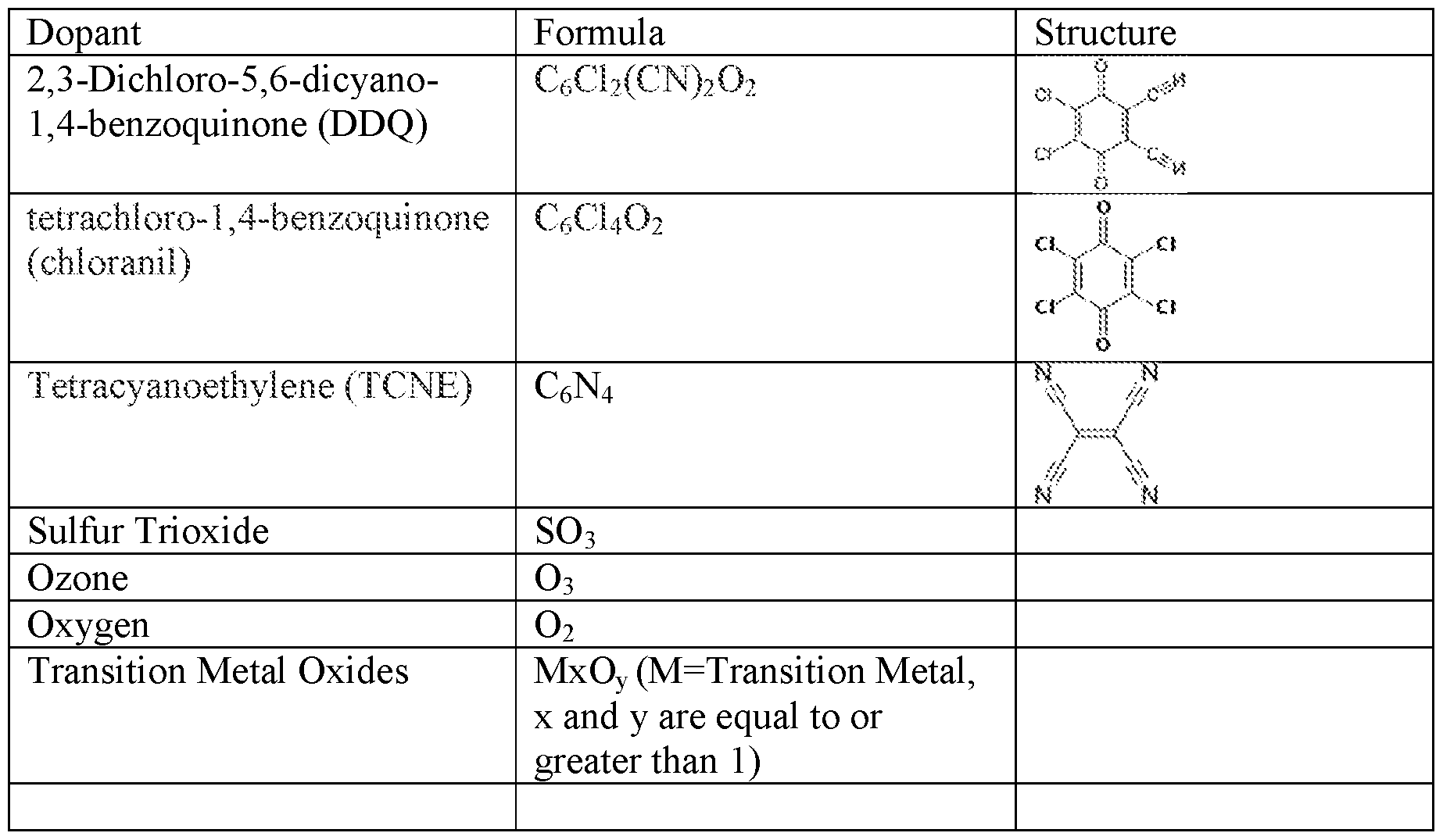
- Dopants that are useful as reactants in the synthesis of the solid ionically conductive polymer material are electron acceptors or oxidants. It is believed that the dopant acts to release ions for ionic transport and mobility, and it is believed to create a site analogous to a charge transfer complex or site within the polymer to allow for ionic conductivity.
- Non- limiting examples of useful dopants are quinones such as: 2,3-dicyano-5,6- dichlorodicyanoquinone (C 8 C1 2 N 2 0 2 ) also known as "DDQ", and tetrachloro-1,4- benzoquinone (C 6 C1 4 0 2 ), also known as chloranil, tetracyanoethylene (C 6 N 4 ) also known as TCNE, sulfur tri oxide ("SO 3 "), ozone (tri oxygen or O3), oxygen (0 2 , including air), transition metal oxides including manganese dioxide (“Mn0 2 "), or any suitable electron acceptor, etc. and combinations thereof.
- quinones such as: 2,3-dicyano-5,6- dichlorodicyanoquinone (C 8 C1 2 N 2 0 2 ) also known as "DDQ”, and tetrachloro-1,4- benzoquinone (C 6 C1 4 0 2 ), also known as chloranil,
- Dopants that are temperature stable at the temperatures of the synthesis heating step are useful, and quinones and other dopants which are both temperature stable and strong oxidizers quinones are very useful.
- Table 2 provides a non-limiting listing of dopants, along with their chemical diagrams.
- Ionic compounds that are useful as reactants in the synthesis of the solid ionically conductive polymer material are compounds that release desired ions during the synthesis of the solid ionically conductive polymer material.
- the ionic compound is distinct from the dopant in that both an ionic compound and a dopant are required.
- the particular ionic compound included in the synthesis depends on the utility desired for the material. For example, in an aspect where it would be desired to have a lithium cation which is ionically mobile in the solid ionically conductive polymer material, a lithium hydroxide, or a lithium oxide convertible to a lithium and hydroxide ion would be appropriate.
- lithium ionic compounds include those used as lithium salts in organic solvents.
- Non-limiting examples include Li 2 0, LiOH, LiN0 3 , LiTFSI (lithium bis-trifluoromethanesulfonimide), LiFSI (Lithium bis(fluorosulfonyl)imide), Lithium bis(oxalato)borate (LiB(C 2 0 4 ) 2 "LiBOB”), lithium triflate LiCF 3 0 3 S (lithium trifluoromethane sulfonate), LiPF6 (lithium hexafluorophosphate), LiBF4 (lithium tetrafluoroborate), LiAsF6 (lithium hexafluoroarsenate) and other lithium salts and combinations thereof.
- LiTFSI lithium bis-trifluoromethanesulfonimide
- LiFSI Lithium bis(fluorosulfonyl)imide
- Hydrated forms (e.g. monohydride) of these compounds can be used to simplify handling of the compounds.
- Inorganic oxides, chlorides and hydroxide are suitable ionic compounds in that they dissociate during synthesis to create at least one anionic and cationic diffusing ion. Any such ionic compound that dissociates to create at least one anionic and cationic diffusing ion would similarly be suitable.
- Multiple ionic compounds can also be useful that result in multiple anionic and cationic diffusing ions can be preferred.
- the purity of the materials is potentially important so as to prevent any unintended side reactions and to maximize the effectiveness of the synthesis reaction to produce a highly conductive material.
- Substantially pure reactants with generally high purities of the dopant, base polymer and the ionic compound are useful, and purities greater than 98% are more useful with even higher purities, e.g. LiOH: 99.6%, DDQ: >98%, and Chloranil: >99% also useful.
- bipolar battery design cross several areas, including flexibility in the overall voltage provided by the battery, increased energy density, decreased internal impedance, and in the case of the Ionic bipolar battery - a high voltage cell with very high safety.
- the voltage flexibility enabled by the bipolar design is important to the market application of the cell, where desirable voltage windows (such as 4 V lithium ion, 12 V for automotive, etc.) can be matched, and is discussed below.
- desirable voltage windows such as 4 V lithium ion, 12 V for automotive, etc.
- a strong benefit also exists in the flexibility that this design gives to considering electrode couples which would normally be discounted because of lower voltage.
- the lower voltage of these electrode couples can be offset by the bipolar design, stacking bipolar cell units and creating a higher overall cell voltage.
- the potential benefits of utilizing lower voltage electrode materials can include low cost, high capacity, improved stability and cycle life, inherent safety and environmentally benign material properties.
- the bipolar battery design not only yields greater battery voltage flexibility, but also opens a much greater array of material choices to improve manufacturing.
- bipolar battery Another aspect of the bipolar battery is the combination of a high voltage system with a fundamentally safe battery chemistry. Safety testing of the bipolar battery has demonstrated low temperatures during direct short circuits and abusive puncture tests. This shows that high voltage batteries, which can be used in place of traditional liquid lithium ion batteries, can also be very safe and benign toward abusive conditions. This provides a significant benefit to the end user of the battery.
- Bipolar batteries provide much more voltage flexibility than existing solutions. By allowing low voltage chemistries to compete with more expensive lithium ion technologies and by minimizing packaging in high voltage batteries for electric vehicle and other applications, bipolar batteries have cost and performance advantages over existing technologies.
- a four-layer bipolar nickel metal hydride battery containing the solid ionically conductive polymer material for example, is 4.8 volts and could be used in consumer electronics applications where battery cost is a driver.
- a ten-layer lithium ion battery with solid ionically conductive polymer material has an electric potential of nearly 40 volts with significantly less packaging than ten four-volt lithium ion cells connected in series.
- Bipolar batteries seek to internally connect multiple electrochemical cells in series.
- the cathode of the first cell shares a current collector with the anode of the next cell to create a series connection. Electrons flow directly through this current collector from the anode to the cathode. At the last anode in the series, electrons flow out into the battery's end current collector, which is connected to an external terminal.
- This configuration results in a battery with a total voltage that is the sum of the individual cell voltages, enabling much more voltage flexibility than with traditional cell layouts.
- FIG. 1 shows this configuration for a three-cell bipolar battery.
- the bipolar battery 10 includes a plurality of both bipolar electrodes and anode- cathode couples or sub-stack assemblies, with the latter being labeled by VI, V2 and V3 for the sub-voltages these couples provide.
- Each bipolar electrode comprises a bipolar current collector 20a and 20b. Adjacent each bipolar current collector is both an anode 30a and 30b, and a cathode 40a and 40b.
- the bipolar electrodes are separated from each other by a layer of the solid ionically conductive polymer material electrolyte 50a.
- Terminal electrodes anode 30d, and cathode 40c are located in coupled opposition to the cathode 40b and anode 30a respectively and separated by the interposed electrolyte comprising the solid ionically conductive polymer electrolyte 50b and 50c respectively.
- an end current collector 60a and 60b are located in electrical connection with each terminal electrode.
- the end current collectors can act a battery terminals or in an aspect can be in electrical connection with battery terminals.
- the battery terminals can be connected to either an open circuit or a load wherein the battery will provide either an open circuit voltage e- or an electron flow to the load.
- the bipolar battery includes at least one bipolar electrode, and in FIG. 1 there is shown two bipolar electrodes positioned adjacent each other. In an aspect where there is a plurality of bipolar electrodes, each would be similarly positioned with a layer of electrolyte therebetween.
- Each bipolar electrode including a positive electrode having a first electrochemically active material on one side of an electrically conducting sheet and a negative electrode having a second electrochemically active material on the other side of the sheet.
- each electrolyte layer comprising a solid ionically conductive polymer material depends on the number of bipolar electrodes, and a plurality plus one of electrolyte layers would be required to accommodate a plurality of bipolar electrodes.
- Each electrolyte layer, containing the solid ionically conductive polymer material enables significant ionic conductivity at room temperature which enables the bipolar battery to both be a stable system and to perform at high drain rates.
- Each terminal electrode i.e. terminal negative electrode (anode) 30d and the terminal positive electrode (cathode) 40c, is not a component of a bipolar electrode but form a sub stack with an opposed electrode that is a bipolar electrode component.
- the terminal negative electrode is located opposed to and in electrochemically coupled relation to a positive electrode located on a first adjacent bipolar electrode with an electrolyte layer interposed therebetween.
- the terminal positive electrode is located opposed to a negative electrode layer on a second adjacent bipolar electrode with an electrolyte layer interposed therebetween.
- each positive electrode 40a, 40b, 40c and the adjacent anode 30a, 30b, 30d comprise a sub-stack which also includes an electrolyte layer.
- components 40b, 50b and 30d comprise a first sub-stack which generates a voltage V3.
- Each sub-stack is separated from an adjacent sub-stack by an electrically conductive sheet, which conducts the electrons from each sub-stack in a series to produce an aggregate battery voltage, as it is in electrical communication with each sub-stack in the battery.
- the sub-stack comprising the electrolyte layer 50a positioned between anode 30b and cathode 40a, and generates voltage V2.
- the second sub-stack is positioned adjacent and in electrical but not ionic communication with the first sub-stack via the bipolar current collector 20b, and also in electrical connection with a third sub-stack via bipolar current collector 20a which is positioned adjacent the second sub-stack and bounds the second sub- stack on one end with the bipolar current collector 20b positioned opposed from current collector layer 20a and bounding the opposite end.
- each sub-stack depends on the relative electropotential of the included electrodes.
- the sub-stack voltage can be is equal to or less than 3 volts or be very high e.g. greater than 4.2 volts, or greater than 5 volts.
- the electropotential of the electrodes depends on the electropotenial of the included electrochemically active materials.
- Anode electrodes can include zinc, aluminum, lithium, an intercalation material and many other electrochemically active materials.
- Cathode electrodes can include manganese dioxide, sulfur, an intercalation and many other electrochemically active materials.
- the bipolar current collectors 20a and 20b are used for both the cathode 40a and 40b and anode 30a and 30b of adjacent bipolar cell units.
- the bipolar battery 10 uses one less current collector for each electrochemical pair, which reduces the volume and weight occupied by inactive components.
- the number of current collectors eliminated from the design can be substantial.
- the bipolar current collector transfers electrons directly between the cathode and anode, across the entire face of the electrodes, the thickness of the current collector can be very thin, even for the highest rate cell designs.
- Bipolar batteries are especially useful for high rate applications, because the bipolar design provides lower internal impedance compared to a traditional battery design. This lower internal impedance results in a battery which is able to be charged and discharged at a faster rate, and provide higher currents for demanding high power applications.
- the reason that the bipolar battery has inherently lower impedance is due to direct current flow across the entire face of the electrodes between bipolar cell units. In a traditional cell, current flows along the electrode from the electrode tab, down to the furthest point. In a bipolar cell, the current can directly transfer between the cathode and anode throughout the entire area of the bipolar current collector, travelling a distance of microns rather than tens of centimeters, which corresponds to the thickness of the bipolar current collector.
- the bipolar current collector 20a and 20b can be copper, aluminum, stainless steel or any highly electrically conductive material that is thin and shaped to be positioned between the anode and cathodes.
- the end current collectors 60a and 60b can be the same material or an identical component as the bipolar current collectors.
- the end current collectors can be electrically conducting tabs which are affixed to the end electrodes to conduct current in and out of the battery from the respective terminals.
- the end current collectors need not act to prevent the proximity of the bipolar electrode anodes and cathode as there is no electrode couple.
- Each anode 30a, 30b and 30d can comprise an electrochemically active material appropriate for the desired electrochemical system.
- the anode-cathode couple is not restrictive as the bipolar battery 10 can comprise any electrochemical couple which includes solid materials as the electrochemically active couple (anode and cathode).
- lithium batteries are described, lithium batteries are an aspect and not the sole electrochemical system.
- the electrochemical couple comprises lithium as the electrochemically active material of the anode
- the anode can comprise lithium metal in an aspect, or a lithium intercalation material in another aspect.
- useful anode materials include typical anode intercalation materials comprising: lithium titanium oxide (LTO), Silicon (Si), germanium (Ge), and tin (Sn) anodes doped and undoped; and other elements, such as antimony (Sb), lead (Pb), Cobalt (Co), Iron (Fe), Titanium (Ti), Nickel (Ni), magnesium (Mg), aluminum (Al), gallium (Ga), Germanium (Ge), phosphorus (P), arsenic (As), bismuth (Bi), and zinc (Zn) doped and undoped; oxides, nitrides, phosphides, and hydrides of the foregoing; and carbons (C) including nanostructured carbon, graphite, graphene and other materials including carbon, and mixtures thereof.
- LTO lithium titanium oxide
- Si Silicon
- Ge germanium
- Sn tin
- other elements such as antimony (Sb), lead (Pb), Cobalt (Co), Iron (Fe),
- anode intercalation material can be mixed with and dispersed within the solid ionically conducting polymer material such that the solid ionically conducting polymer material can act to ionically conduct the lithium ions to and from the intercalation material during both intercalation and deintercalation (or lithiation/delithiation).
- Electrically conductive additives can be additionally added to such an intercalation anode to enable electrons from flow from the electrochemically active material to the adjacent current collector.
- the lithium can be added with the cathode material, added to the anode as lithium foil, dispersed in the solid ionically conducting polymer material, or added to both battery components.
- the solid ionically conductive polymer electrolyte acts to transport the lithium metal to and from the anode and therefore must be positioned within the battery so it is enabled to do so.
- the solid ionically conductive polymer electrolyte can be positioned as a film layer, or any other shape which enables the solid ionically conductive polymer electrolyte to perform its lithium ion conduction.
- the thickness of the solid ionically conductive polymer electrolyte can be in a desired range of uniform thicknesses such as 200 to 25 micrometers or thinner.
- a rheological or extrusion aid can be added such as EPDM (ethylene propylene diene monomer) in amounts necessary to affect the desired extrusion properties.
- Each cathode 40a, 40b and 40c can comprise an electrochemically active material appropriate for the desired electrochemical system and the anode-cathode couple as the bipolar battery 10 can comprise any electrochemical couple which includes solid materials as the electrochemically active couple (anode and cathode).
- the electrochemically active couple anode and cathode.
- Typical electrochemically active cathode compounds which can be used include but are not limited to: NCA - Lithium Nickel Cobalt Aluminum Oxide (LiNiCoA10 2 ); NCM (NMC) - Lithium Nickel Cobalt Manganese Oxide (LiNiCoMn0 2 ); LFP - Lithium Iron Phosphate (LiFeP0 4 ); LMO - Lithium Manganese Oxide (LiMn 2 0 4 ); LCO - Lithium Cobalt Oxide (LiCo0 2 ); lithium oxides tor phosphates that contain nickel, cobalt or manganese, and LiTiS2, LiNi02, and other layered materials, other spinels, other olivines and tavorites, and combinations thereof.
- the electrochemically active cathode compounds can be an intercalation material or a cathode material that reacts with the lithium or other electrochemically active cathode material in a solid state redox or conversion_reaction.
- conversion cathode materials include: metal halides including but not limited to metal fluorides such as FeF 2 , BiF 3 , CuF 2 , and NiF 2 , and metal chlorides including but not limited to FeCl 3 , FeCl 2 , CoCl 2 , NiCl 2 , CuCl 2 , and AgCl; Sulfur (S); Selenium (Se); Tellerium (Te); Iodine (I); Oxygen (O); and related materials such as but not limited to pyrite (FeS 2 ) and Li 2 S .
- metal fluorides such as FeF 2 , BiF 3 , CuF 2 , and NiF 2
- metal chlorides including but not limited to FeCl 3 , FeCl 2 ,
- an aspect is to increase the energy density by enabling as high a voltage battery as possible, therefore high voltage cathode compounds are preferred in this aspect.
- Certain NCM or NMC material can provide such high voltages with high concentrations of the nickel atom.
- NCMs that have an atomic percentage of nickel which is greater than that of cobalt or manganese, such as NCM 7i2 , NCM 721 , NCM 8 n, NCM 532 , and NCM 523 are useful to provide a higher voltage relative the anode electrochemically active material.
- the cathode like the anode, can be dispersed within the solid ionically conductive polymer material, by being mixed with it and an electrically conductive material such as carbon or graphite.
- the cathode can be formed onto the bipolar current collector or formed as an independent structure and place adjacent the bipolar current collector.
- Example 1 The battery article and its components are described here, and ways to make and use them are illustrated in the following examples.
- Example 1
- PPS and chloranil powder are mixed in a 4.2: 1 molar ratio (base polymer monomer to dopant ratio greater than 1 : 1).
- the mixture is then heated in argon or air at a temperature up to 350°C for about twenty-four (24) hours at atmospheric pressure.
- a color change is observed confirming the creation of charge transfer complexes in the polymer-dopant reaction mixture.
- the reaction mixture is then reground to a small average particle size between 1-40 micrometers.
- LiTFSI powder (12 wt. % of total mixture) is then mixed with the reaction mixture to create the synthesized solid, ionically conducting polymer material.
- the solid, ionically conducting polymer material which is used as a solid ionically conductive polymer electrolyte in this aspect is referred to as a solid polymer electrolyte when thus used.
- the solid ionically conductive polymer electrolyte can be used in multiple locations in a battery, including in an electrode, or as a standalone dielectric, non-electrochemically active electrolyte interposed between electrodes.
- the solid ionically conductive polymer electrolyte can be the same material in all battery application, and in the aspect of a lithium battery if the ionic mobility of lithium is maximized, this property and attribute of the solid ionically conductive polymer electrolyte allows the solid ionically conductive polymer electrolyte to function well in an anode, cathode and as a standalone dielectric, non- electrochemically active electrolyte interposed between anode and cathode electrodes.
- the solid ionically conductive polymer electrolyte can vary so as to accommodate different properties that may be desired in an application.
- an electronically conductive material could be added to the solid ionically conductive polymer electrolyte or integrated into the solid ionically conductive polymer electrolyte during its synthesis thus increasing the electrical conductivity of the solid ionically conductive polymer electrolyte and making it suitable for use in an electrode and reducing and or eliminating the need for additional electrical conductive additives in such an electrode. If so used, such a formulation would not be appropriate for use as a standalone dielectric, non-electrochemically active electrolyte interposed between anode and cathode electrodes as it is electrically conductive and would act to short the battery.
- solid ionically conductive polymer electrolyte in an anode, cathode and as a standalone dielectric, non-electrochemically active electrolyte interposed between anode and cathode electrodes enables a battery designer to take advantage of the thermoplastic nature of the solid ionically conductive polymer electrolyte.
- the standalone dielectric, non-electrochemically active electrolyte can be thermoformed onto the anode or cathode by being heated and fixed thereto, such as in a lamination process, or by being co- extruded and thus formed together with the electrode.
- all three battery components include the solid ionically conductive polymer electrolyte and are thermoformed together or coextruded to form a battery.
- Electronic conductivity of the synthesized material is measured using potentiostatic method between blocking electrodes, and was determined to be 6.5 x 10 "9 S/cm or lower (less conductive) than 1 x 10 "8 S/cm.
- Diffusivity measurements were conducted on the synthesized material.
- PGSE- MR measurements were made using a Varian-S Direct Drive 300 (7.1 T) spectrometer. Magic angle spinning technique was used to average out chemical shift anisotropy and dipolar interaction.
- Pulsed gradient spin stimulated echo pulse sequence was used for the self- diffusion (diffusivity) measurements.
- the measurements of the self-diffusion coefficients for the cation and anion in each material sample were made using 1H and 7 Li nuclei, respectively.
- the conductivity of the material is calculated via the Nernst-Einstein equation, using the measured diffusion measurements, it was determined the associated calculated conductivity to be much greater than the measured conductivity. The difference was on average at least an order of magnitude (or lOx). Therefore, it is believed that conductivity can be improved by improving ion dissociation, and the calculated conductivities can be considered within the range of conductivity.
- the cation transference number can be estimated via equation (1) from the diffusion coefficient data as: t+ ⁇ D+/(D+ + D-) (1) where D+ and D- refer to the diffusion coefficients of the Li cation and TFSI anion, respectively. From the above data, one obtains a t+ value of about 0.7 in the solid ionically conductive polymer material. This property of high cation transference number has important implications to battery performance. Ideally one would prefer a t+ value of 1.0, meaning that the Li ions carry all the electric current. Anion mobility results in electrode polarization effects which can limit battery performance. The calculated transference number of 0.7 is not believed to have been observed in any liquid or PEO based electrolyte. Although ion association may affect the calculation, electrochemical results confirm the transference number range of between 0.65 and 0.75.
- the t+ is dependent on anion diffusion as lithium cation diffusion is high.
- the cation transference number is always above 0.5, and as the anion is mobile the cation transference number must also be less than 1.0. It is believed that a survey of lithium salts as ionic compounds would produce this range of cation transference numbers greater than 0.5 and less than 1.0.
- some ceramics have been reported to have high diffusion numbers, however such ceramics only transport a single ion, therefore the cation transference number reduces to 1.0 as the D- is zero.
- Example 1 Additional solid ionically conductive polymer materials are listing in Table 3, along with the material synthesized and described in Example 1 (PPS-Chloranil-LiTFSI), which were prepared using the synthesis method of Example 1, along with their reactants and associated ionic conductivity (EIS method) at room temperature.
- solid ionically conductive polymer materials Various physical properties of the solid ionically conductive polymer materials are measured and it is determined that the solid ionically conductive polymer materials: electronic conductivity of the solid ionically conductive polymer material is less than 1 x 10 "8 S/cm at room temperature; can be molded to thicknesses from 200 micrometers down to 20 micrometers; possesses significant ionic mobility to very low temperatures, e.g. -40°C, and have ionic conductivities at room temperature greater than 1.0E-05 S/cm, l .OE-04 S/cm, and 1.0E-03 S/cm, and these ionic conductivities include lithium as one of the mobile ions being conducted through the solid ionically conductive polymer material.
- the solid ionically conductive polymer electrolyte of Example 2 was used to make a bipolar secondary lithium cell.
- the cell comprised a lithium metal anode
- the solid ionically conductive polymer electrolyte was used an an electrolyte layer and interposed between the anode and a slurry cathode.
- the slurry cathode also comprised the solid ionically conductive polymer electrolyte and the cathode is manufactured using a stepwise process.
- the process initially includes a polyvinylidene difluoride (PVDF) binder in a solvent such as N-Methyl-2- pyrrolidone ( MP) or Dimethylacetamide (DMA). Electrically conductive carbon and graphite and the solid ionically conductive polymer electrolyte are then added in a first mixing step in which the carbon and solid ionically conductive polymer electrolyte remain stable and insoluble in the binder solvent. This first mixture is then mixed in a second mixing step with a electrochemically active cathode material such as Lithium cobalt oxide (LiCo0 2 ) (“LCO”) to create a slurry mix which is then coated onto a cathode collector. After a drying step in which the binder solvent is driven out of the cathode, the cathode is calendared to create a high density cathode.
- PVDF polyvinylidene difluoride
- MP N-Methyl-2- pyrroli
- Table 4 details composition ranges for each of the cathode components included in the described slurry cathode process.
- the high density cathode is about 15 to 115 micrometers in thickness, and has a cathode coating density in the range of 1.2 to 3.6 g/cc.
- Bipolar batteries were assembled using Li metal anodes. Cathodes were prepared incorporating electrochemically active material listed in Table 5, and according to the method described in Example 3, and the lithium metal anode is positioned opposite the cathode on the current collector to create a bipolar electrode including the solid ionically conductive polymer material. A film of the solid ionically conductive polymer material is located between the anodes and cathodes layers or between the bipolar electrodes. Three layers of bipolar electrodes were used in the battery giving a total cell voltage of listed in Table 5. Since the solid ionically conductive polymer material was used in this battery, no attempt was made to seal between the bipolar electrodes; and all of the layers were stacked directly adjacent each other.
- the battery was vacuum sealed in aluminum laminate pouch material in a manner so the conductive tabs protrude from the pouch to act as terminal leads for the bipolar pouch cell.
- the bipolar pouch cells (batteries) from Example 4 are tested to determine voltage stability, performance, cycling efficiency and shelf life.
- a bipolar pouch cells comprising a NCM cathode was tested for stability.
- FIG. 2A is a charge curve which displays stable voltage for the first cycle of the cell.
- FIG. 2B shows the high rate pulse discharge of this same bipolar cell, and demonstrates the bipolar cell is able to handle current density as high as 3.0 mA/cm2, well above the minimum voltage of the battery..
- the Li metal/solid ionically conductive polymer material/NCM bipolar cell was pulse discharge tested for 5 sec pulse lengths at currents of 5, 20, 40, 80 and 120 mA. These currents correspond to 0.125, 0.5, 1.0, 2.0, and 3.0 mA/cm2 current density, respectively. All of the currents utilized here were readily handled by the cell, with the minimum voltage significantly above the 9 V minimum voltage for the cell.
- the bipolar pouch cells (batteries) from Example 4 were additionally tested to determine voltage stability, performance, cycling efficiency and shelf life. Specifically, one of the bipolar pouch cells comprising a LCO cathode was cycled with a nine (9) hour rest after charge. Referring to FIG. 3, the charge voltage exceeds 12 volts on the first cycle, and which is repeated in the second cycle. The nine (9) hour rest time after the initial charge demonstrates the voltage stability of the cell, since the open circuit storage voltage remains stable, and above 12 V during this time period.
- a longer discharge curve is shown which displays the entire second cycle. From the first two charge-discharge cycles a cyclic efficiency can be calculated using coulombs required for the charge, and coulombs derived during discharge. The coulombic measurements can be normalized relative to the weight of the electrochemically active cathode material for a mAh/gram capacity measurement. The discharge value is divided by the charge value for a cycle and multiplied by 100 to yield a n-cycle efficiency. The first cycle charge capacity was calculated to be 162.8 mAh/g, with the associated discharge capacity 146.3 mAh/g. In the second cycle, the first cycle charge capacity was calculated to be 149.1 mAh/g, with the associated discharge capacity 148.6 mAh/g for a second cycle cyclic efficiency of over 99%.
- FIG. 5 there is shown an open circuit voltage plot of the same bipolar pouch cell over many days. To the extent there was shorting, bridging or other interaction between the electrodes the OCV would show a change. However, the bipolar cell is stable over a many week time period.
- a bipolar battery was assembled using Li metal anodes, and sulfur cathodes incorporating sulfur electrochemically active material and the solid ionically conductive polymer material from Example 1, with an electrically conductive copper collector positioned there between to form a bipolar electrode.
- Three layers of anode/ solid ionically conductive polymer material /cathode were used in the battery giving a total cell voltage of approximately 7.0 V (each sub-stack contributing ⁇ 2.33 V to the total bipolar battery voltage).
- the battery was vacuum sealed in aluminum laminate pouch material.
- the open circuit voltage of the bipolar battery was monitored over several months to determine the stability of the cell.
- a stable cell chemistry would be expected to have an open circuit voltage that is stable over time.
- the results are presented in FIG. 6, which show OCV stability at the predicted 7.0 Volts for over one half year.
- the impedance change was very slight, and varied over time, most likely due to slight changes in room temperature during the impedance measurement.
- FIG. 7 which includes the initial impedance and the 4- month storage impedance, which are virtually identical, the cell does not change in impedance over several months of storage - thus the cell has very stable components.
- bipolar batteries were assembled using two or three bipolar cell stacks. These bipolar batteries were constructed using Mn0 2 cathodes (Mn02 mixed with the solid ionically conductive polymer material, and an electrically conductive graphite or similar material) and Aluminum anodes, both containing the solid ionically conductive polymer material.
- the solid ionically conductive polymer material was prepared according to Example 1, however the ionic compound used was lithium hydroxide monohydride.
- Alkaline liquid electrolyte (potassium hydroxide solution) was used and properly sealed in these cells. No cell shorting or electrolyte leakage was observed. These cells have demonstrated capabilities to power electronic devices such as iPod Nano, LED lights, etc.
Landscapes
- Chemical & Material Sciences (AREA)
- General Chemical & Material Sciences (AREA)
- Electrochemistry (AREA)
- Chemical Kinetics & Catalysis (AREA)
- Engineering & Computer Science (AREA)
- Manufacturing & Machinery (AREA)
- Inorganic Chemistry (AREA)
- General Physics & Mathematics (AREA)
- Physics & Mathematics (AREA)
- Dispersion Chemistry (AREA)
- Condensed Matter Physics & Semiconductors (AREA)
- Materials Engineering (AREA)
- Life Sciences & Earth Sciences (AREA)
- Sustainable Development (AREA)
- Sustainable Energy (AREA)
- Secondary Cells (AREA)
- Battery Electrode And Active Subsutance (AREA)
Abstract
Description


Claims
Priority Applications (6)
| Application Number | Priority Date | Filing Date | Title |
|---|---|---|---|
| CN201680044813.8A CN108140805B (en) | 2015-06-04 | 2016-06-06 | Solid state bipolar battery |
| EP16804636.5A EP3304620A4 (en) | 2015-06-04 | 2016-06-06 | Solid state bipolar battery |
| US15/579,503 US11749833B2 (en) | 2012-04-11 | 2016-06-06 | Solid state bipolar battery |
| KR1020187000304A KR102608943B1 (en) | 2015-06-04 | 2016-06-06 | solid state bipolar battery |
| JP2017562579A JP6944379B2 (en) | 2015-06-04 | 2016-06-06 | Solid bipolar battery |
| US18/220,063 US20230352726A1 (en) | 2012-04-11 | 2023-07-10 | Solid state bipolar battery |
Applications Claiming Priority (2)
| Application Number | Priority Date | Filing Date | Title |
|---|---|---|---|
| US201562170959P | 2015-06-04 | 2015-06-04 | |
| US62/170,959 | 2015-06-04 |
Related Parent Applications (4)
| Application Number | Title | Priority Date | Filing Date |
|---|---|---|---|
| US13/861,170 Continuation-In-Part US9819053B1 (en) | 2012-04-11 | 2013-04-11 | Solid electrolyte high energy battery |
| US14/559,430 Continuation-In-Part US9742008B2 (en) | 2012-04-11 | 2014-12-03 | Solid, ionically conducting polymer material, and methods and applications for same |
| US14/676,173 Continuation-In-Part US11145857B2 (en) | 2012-04-11 | 2015-04-01 | High capacity polymer cathode and high energy density rechargeable cell comprising the cathode |
| US15/148,085 Continuation-In-Part US11251455B2 (en) | 2012-04-11 | 2016-05-06 | Solid ionically conducting polymer material |
Related Child Applications (2)
| Application Number | Title | Priority Date | Filing Date |
|---|---|---|---|
| US15/579,503 A-371-Of-International US11749833B2 (en) | 2012-04-11 | 2016-06-06 | Solid state bipolar battery |
| US18/220,063 Continuation US20230352726A1 (en) | 2012-04-11 | 2023-07-10 | Solid state bipolar battery |
Publications (1)
| Publication Number | Publication Date |
|---|---|
| WO2016197098A1 true WO2016197098A1 (en) | 2016-12-08 |
Family
ID=57442272
Family Applications (1)
| Application Number | Title | Priority Date | Filing Date |
|---|---|---|---|
| PCT/US2016/036010 WO2016197098A1 (en) | 2012-04-11 | 2016-06-06 | Solid state bipolar battery |
Country Status (6)
| Country | Link |
|---|---|
| US (1) | US11749833B2 (en) |
| EP (1) | EP3304620A4 (en) |
| JP (1) | JP6944379B2 (en) |
| KR (1) | KR102608943B1 (en) |
| CN (1) | CN108140805B (en) |
| WO (1) | WO2016197098A1 (en) |
Cited By (10)
| Publication number | Priority date | Publication date | Assignee | Title |
|---|---|---|---|---|
| EP3367472A1 (en) * | 2017-02-28 | 2018-08-29 | Commissariat à l'énergie atomique et aux énergies alternatives | Electrochemical storage cell with bipolar architecture, with high voltage per electrochemical cell |
| CN110800136A (en) * | 2017-07-28 | 2020-02-14 | 株式会社Lg化学 | Positive electrode for lithium-sulfur battery and lithium-sulfur battery comprising same |
| CN112154564A (en) * | 2017-12-21 | 2020-12-29 | 离子材料公司 | Battery electrode with solid polymer electrolyte and water-soluble binder |
| US11031599B2 (en) | 2012-04-11 | 2021-06-08 | Ionic Materials, Inc. | Electrochemical cell having solid ionically conducting polymer material |
| US11145899B2 (en) | 2015-06-04 | 2021-10-12 | Ionic Materials, Inc. | Lithium metal battery with solid polymer electrolyte |
| US11152657B2 (en) | 2012-04-11 | 2021-10-19 | Ionic Materials, Inc. | Alkaline metal-air battery cathode |
| US11251455B2 (en) | 2012-04-11 | 2022-02-15 | Ionic Materials, Inc. | Solid ionically conducting polymer material |
| US11342559B2 (en) | 2015-06-08 | 2022-05-24 | Ionic Materials, Inc. | Battery with polyvalent metal anode |
| US11605819B2 (en) | 2015-06-08 | 2023-03-14 | Ionic Materials, Inc. | Battery having aluminum anode and solid polymer electrolyte |
| US11611104B2 (en) | 2012-04-11 | 2023-03-21 | Ionic Materials, Inc. | Solid electrolyte high energy battery |
Families Citing this family (9)
| Publication number | Priority date | Publication date | Assignee | Title |
|---|---|---|---|---|
| CN106165154B (en) | 2013-12-03 | 2020-03-13 | 离子材料公司 | Solid ionically conductive polymer material and uses thereof |
| CN106489217B (en) | 2014-04-01 | 2021-07-30 | 离子材料公司 | High capacity polymer cathode and high energy density rechargeable battery including the same |
| EP3574542A4 (en) | 2017-01-26 | 2020-09-02 | Ionic Materials, Inc. | Alkaline battery cathode with solid polymer electrolyte |
| TWI676315B (en) * | 2017-10-20 | 2019-11-01 | 輝能科技股份有限公司 | Composite battery cell |
| EP3608995B1 (en) * | 2018-08-08 | 2021-10-20 | Prologium Technology Co., Ltd. | Horizontal composite electricity supply element group |
| EP3608997A1 (en) * | 2018-08-08 | 2020-02-12 | Prologium Technology Co., Ltd. | Horizontal composite electricity supply structure |
| CN116325282A (en) * | 2020-10-29 | 2023-06-23 | 株式会社Lg新能源 | Bipolar all-solid battery including porous support layer |
| CN115117437A (en) * | 2021-03-18 | 2022-09-27 | 南京博驰新能源股份有限公司 | Solid electrolyte and preparation method thereof |
| WO2023158995A2 (en) * | 2022-02-18 | 2023-08-24 | Northeastern University | Sulfide based all-solid-state batteries enabled by bipolar stacking |
Citations (3)
| Publication number | Priority date | Publication date | Assignee | Title |
|---|---|---|---|---|
| US5582937A (en) * | 1994-10-12 | 1996-12-10 | Bipolar Technologies, Inc. | Bipolar battery cells, batteries and methods |
| US20030162087A1 (en) * | 2002-02-12 | 2003-08-28 | Clarke Robert Lewis | Electric devices with improved bipolar electrode |
| US20080292953A1 (en) * | 2007-04-20 | 2008-11-27 | Nissan Motor Co., Ltd. | Secondary battery with non-aqueous solution |
Family Cites Families (206)
| Publication number | Priority date | Publication date | Assignee | Title |
|---|---|---|---|---|
| US2638489A (en) | 1951-03-07 | 1953-05-12 | Ruben Samuel | Primary cell |
| FI40176C (en) | 1961-04-24 | 1968-11-11 | High power galvanic battery | |
| US3336279A (en) | 1964-04-08 | 1967-08-15 | Franklin Institute | Polymerization of vinyl amino compounds with pi complex-forming electron acceptor compounds |
| US3502606A (en) | 1966-01-19 | 1970-03-24 | Celanese Corp | Production of shaped polybenzimidazole articles |
| US4243732A (en) | 1979-06-28 | 1981-01-06 | Union Carbide Corporation | Charge transfer complex cathodes for solid electrolyte cells |
| JPS58167097A (en) | 1982-03-29 | 1983-10-03 | Nikkei Giken:Kk | Flux for brazing |
| US4471037A (en) | 1982-04-16 | 1984-09-11 | United Kingdom Atomic Energy Authority | Solid state electrochemical cell |
| US4465744A (en) | 1982-11-30 | 1984-08-14 | The United States Of America As Represented By The United States Department Of Energy | Super ionic conductive glass |
| JPS59157151A (en) | 1983-02-28 | 1984-09-06 | Dainippon Ink & Chem Inc | Electrically-conductive organic thermoplastic composition |
| GB8333388D0 (en) | 1983-12-15 | 1984-01-25 | Raychem Ltd | Materials for electrical devices |
| US4654279A (en) | 1986-07-10 | 1987-03-31 | The United States Of America As Represented By The Secretary Of The Navy | Interpenetrating-network polymeric electrolytes |
| US4720910A (en) | 1987-06-16 | 1988-01-26 | Mhb Joint Venture | Method for preparing encapsulated cathode material |
| US4804594A (en) | 1987-10-13 | 1989-02-14 | Allied-Signal Inc. | Predoped conductive polymers as battery electrode materials |
| US5227043A (en) | 1989-01-07 | 1993-07-13 | Hitachi Maxell, Ltd. | Ionic conductive polymer electrolyte and cell comprising the same |
| US5169494A (en) | 1989-03-27 | 1992-12-08 | Matsushita Electric Industrial Co., Ltd. | Fine pattern forming method |
| US4925751A (en) | 1989-04-26 | 1990-05-15 | Shackle Dale R | High power solid state electrochemical laminar cell |
| US5160880A (en) | 1989-05-10 | 1992-11-03 | Allied-Signal Inc. | Method and apparatus for charging and testing batteries |
| US5147739A (en) | 1990-08-01 | 1992-09-15 | Honeywell Inc. | High energy electrochemical cell having composite solid-state anode |
| EP0497442A3 (en) | 1991-01-29 | 1993-03-03 | Advanced Micro Devices, Inc. | Multi-peripheral controller |
| JP2940181B2 (en) | 1991-02-22 | 1999-08-25 | 松下電器産業株式会社 | Solid electrode composition |
| JPH0582114A (en) | 1991-09-18 | 1993-04-02 | Fuji Photo Film Co Ltd | Secondary battery |
| US5506073A (en) | 1992-06-22 | 1996-04-09 | Arizona State University (Arizona Board Of Regents, A Body Corporate Acting On Behalf Of Arizona State University) | Lithium ion conducting electrolytes |
| FR2695254B1 (en) | 1992-09-02 | 2003-01-10 | Conservatoire Nal Arts Metiers | Solid alkaline polymer electrolyte, electrode and electrochemical generator comprising such an electrolyte. |
| US5917693A (en) | 1992-10-26 | 1999-06-29 | Dai-Ichi Kogyo Seiyaku Co., Ltd. | Electrically conductive polymer composition |
| US5378560A (en) | 1993-01-21 | 1995-01-03 | Fuji Photo Film Co., Ltd. | Nonaqueous secondary battery |
| US5518841A (en) | 1993-02-12 | 1996-05-21 | Matsushita Electric Industrial Co., Ltd. | Composite cathode |
| US5403675A (en) | 1993-04-09 | 1995-04-04 | Maxdem, Incorporated | Sulfonated polymers for solid polymer electrolytes |
| US5460905A (en) | 1993-06-16 | 1995-10-24 | Moltech Corporation | High capacity cathodes for secondary cells |
| US5340368A (en) | 1993-08-04 | 1994-08-23 | Valence Technology, Inc. | Method for in situ preparation of an electrode composition |
| US5599355A (en) | 1993-08-20 | 1997-02-04 | Nagasubramanian; Ganesan | Method for forming thin composite solid electrolyte film for lithium batteries |
| CA2111757C (en) | 1993-12-17 | 2004-03-16 | Lijun Bai | Rechargeable manganese dioxide cathode |
| US5648187A (en) | 1994-02-16 | 1997-07-15 | Moltech Corporation | Stabilized anode for lithium-polymer batteries |
| EP0710313B1 (en) | 1994-04-25 | 2000-05-03 | EMPA Eidgenössische Materialprüfungs- und Forschungsanstalt | Anchorage device for high-performance fiber composite cables |
| US5595839A (en) * | 1994-10-13 | 1997-01-21 | Yardney Technical Products, Inc. | Bipolar lithium-ion rechargeable battery |
| JP2638511B2 (en) | 1994-11-02 | 1997-08-06 | 松下電器産業株式会社 | Manufacturing method of electrophotographic photoreceptor |
| US6376123B1 (en) | 1994-11-23 | 2002-04-23 | Polyplus Battery Company | Rechargeable positive electrodes |
| US5620811A (en) | 1995-05-30 | 1997-04-15 | Motorola, Inc. | Lithium polymer electrochemical cells |
| WO1997020768A1 (en) | 1995-12-07 | 1997-06-12 | Sandia Corporation | Methods of preparation of carbon materials for use as electrodes in rechargeable batteries |
| US5989742A (en) | 1996-10-04 | 1999-11-23 | The Research Foundation Of State University Of New York | Blend membranes based on sulfonated poly(phenylene oxide) for enhanced polymer electrochemical cells |
| JP3702318B2 (en) | 1996-02-09 | 2005-10-05 | 日本電池株式会社 | Non-aqueous electrolyte battery electrode and non-aqueous electrolyte battery using the electrode |
| JP3371320B2 (en) | 1996-07-08 | 2003-01-27 | ソニー株式会社 | Method for producing polymer electrolyte |
| US5688613A (en) | 1996-04-08 | 1997-11-18 | Motorola, Inc. | Electrochemical cell having a polymer electrolyte |
| US6514640B1 (en) | 1996-04-23 | 2003-02-04 | Board Of Regents, The University Of Texas System | Cathode materials for secondary (rechargeable) lithium batteries |
| TW446731B (en) | 1996-08-20 | 2001-07-21 | Daiso Co Ltd | Polymeric solid electrolyte |
| WO1998016960A2 (en) * | 1996-10-11 | 1998-04-23 | Massachusetts Institute Of Technology | Polymer electrolyte, intercalation compounds and electrodes for batteries |
| CN1242877A (en) | 1996-11-01 | 2000-01-26 | 纳幕尔杜邦公司 | Highly conductive ion exchange polymer and process |
| US5888672A (en) | 1997-02-12 | 1999-03-30 | Gustafson; Scott D. | Polyimide battery |
| WO1998042037A1 (en) | 1997-03-17 | 1998-09-24 | Motorola Inc. | Electrochemical cell having a polymer blend electrolyte |
| JP3168962B2 (en) | 1997-11-04 | 2001-05-21 | 日本電気株式会社 | Battery |
| US6110619A (en) | 1997-12-19 | 2000-08-29 | Moltech Corporation | Electrochemical cells with cationic polymers and electroactive sulfur compounds |
| US6210831B1 (en) | 1997-12-19 | 2001-04-03 | Moltech Corporation | Cathodes comprising electroactive sulfur materials and secondary batteries using same |
| US6074773A (en) | 1998-03-06 | 2000-06-13 | Ballard Power Systems Inc. | Impregnation of microporous electrocatalyst particles for improving performance in an electrochemical fuel cell |
| US20030069343A1 (en) | 1998-08-06 | 2003-04-10 | Paul Smith | Melt-processible poly(tetrafluoroethylene) |
| US6183914B1 (en) | 1998-09-17 | 2001-02-06 | Reveo, Inc. | Polymer-based hydroxide conducting membranes |
| US6190426B1 (en) | 1998-12-17 | 2001-02-20 | Moltech Corporation | Methods of preparing prismatic cells |
| US6274261B1 (en) | 1998-12-18 | 2001-08-14 | Aer Energy Resources, Inc. | Cylindrical metal-air battery with a cylindrical peripheral air cathode |
| IT1307756B1 (en) | 1999-02-05 | 2001-11-19 | Ausimont Spa | ELECTROLYTE POLYMERS FOR LITHIUM RECHARGEABLE BATTERIES. |
| FR2790330B1 (en) | 1999-02-25 | 2001-05-04 | Cit Alcatel | LITHIUM RECHARGEABLE ELECTROCHEMICAL GENERATOR POSITIVE ELECTRODE WITH ALUMINUM CURRENT COLLECTOR |
| US6849702B2 (en) | 1999-02-26 | 2005-02-01 | Robert W. Callahan | Polymer matrix material |
| US20050112471A1 (en) | 1999-02-26 | 2005-05-26 | Muguo Chen | Nickel zinc electrochemical cell incorporating dendrite blocking ionically conductive separator |
| US6358651B1 (en) | 1999-02-26 | 2002-03-19 | Reveo, Inc. | Solid gel membrane separator in rechargeable electrochemical cells |
| CA2268316C (en) | 1999-04-07 | 2003-09-23 | Hydro-Quebec | Lipo3 composite |
| US6652440B1 (en) | 1999-05-04 | 2003-11-25 | Moltech Corporation | Electroactive polymers of high sulfur content for use in electrochemical cells |
| US6413676B1 (en) | 1999-06-28 | 2002-07-02 | Lithium Power Technologies, Inc. | Lithium ion polymer electrolytes |
| US6461724B1 (en) | 1999-08-30 | 2002-10-08 | 3M Innovative Properties Company | Microporous material resistant to capillary collapse |
| US6664006B1 (en) | 1999-09-02 | 2003-12-16 | Lithium Power Technologies, Inc. | All-solid-state electrochemical device and method of manufacturing |
| US6645675B1 (en) | 1999-09-02 | 2003-11-11 | Lithium Power Technologies, Inc. | Solid polymer electrolytes |
| WO2001026175A1 (en) | 1999-10-06 | 2001-04-12 | Sarnoff Corporation | Metal-air battery device |
| KR100515571B1 (en) | 2000-02-08 | 2005-09-20 | 주식회사 엘지화학 | Stacked electrochemical cell |
| US6815121B2 (en) | 2000-07-31 | 2004-11-09 | Electrovaya Inc. | Particulate electrode including electrolyte for a rechargeable lithium battery |
| KR100378007B1 (en) | 2000-11-22 | 2003-03-29 | 삼성에스디아이 주식회사 | Positive electrode for lithium-sulfur battery and lithium-sulfur battery comprising same |
| JP2002358959A (en) | 2001-03-27 | 2002-12-13 | Showa Denko Kk | Positive electrode active substance, its manufacturing method and paste, positive electrode and non-aqueous electrolyte secondary battery using the same |
| US6727343B2 (en) | 2001-04-17 | 2004-04-27 | Phoenix Innovation, Inc. | Heteroatomic polymer for more efficient solid polymer electrolytes for lithium batteries |
| US7005213B2 (en) | 2001-05-24 | 2006-02-28 | Rayovac Corporation | Ionically conductive additive for zinc-based anode in alkaline electrochemical cells |
| JP2002352799A (en) | 2001-05-30 | 2002-12-06 | Hitachi Ltd | Method for manufacturing nonaqueous electrolyte secondary battery |
| KR20040047780A (en) * | 2001-07-27 | 2004-06-05 | 메사추세츠 인스티튜트 오브 테크놀로지 | Battery structures, self-organizing structures and related methods |
| US7226549B2 (en) | 2001-12-10 | 2007-06-05 | Uchicago Argonne, Llc | High cation transport polymer electrolyte |
| JP4088755B2 (en) | 2002-02-20 | 2008-05-21 | 株式会社ジーエス・ユアサコーポレーション | Nonaqueous electrolyte secondary battery |
| JP2003242961A (en) | 2002-02-20 | 2003-08-29 | Dainippon Printing Co Ltd | Battery terminal and packaging material for battery unit using the same |
| KR100660483B1 (en) | 2002-04-15 | 2006-12-22 | 히다치 막셀 가부시키가이샤 | Ion-conductive electrolyte and cell employing the same |
| DE60305570T2 (en) | 2002-04-24 | 2007-05-03 | Merck Patent Gmbh | Reactive mesogenic benzodithiophenes |
| JP4228593B2 (en) | 2002-05-29 | 2009-02-25 | ソニー株式会社 | Nonaqueous electrolyte secondary battery |
| US6916577B2 (en) | 2002-07-31 | 2005-07-12 | The Gillette Company | Alkaline cell with polymer electrolyte |
| DE10240032A1 (en) | 2002-08-27 | 2004-03-11 | Creavis Gesellschaft Für Technologie Und Innovation Mbh | Ion-conducting battery separator for lithium batteries, process for their production and their use |
| CN1679192A (en) | 2002-09-20 | 2005-10-05 | 株式会社钟化 | Proton conducting polymer film and method for production thereof |
| US20040076881A1 (en) | 2002-10-17 | 2004-04-22 | Bowden William L. | Method of making a battery |
| US7070882B1 (en) | 2002-11-19 | 2006-07-04 | The United States Of America As Represented By The Secretary Of The Navy | Reactive metal hydrogel/inert polymer composite anode and primary metal-air battery |
| US20040157101A1 (en) | 2003-02-11 | 2004-08-12 | Smedley Stuart I. | Fuel cell electrode assembly |
| US20040161671A1 (en) | 2003-02-13 | 2004-08-19 | Medtronic, Inc. | Liquid electrolyte for an electrochemical cell |
| JP2004265675A (en) | 2003-02-28 | 2004-09-24 | Sanyo Electric Co Ltd | Non-aqueous electrolyte battery |
| US20040253520A1 (en) | 2003-05-13 | 2004-12-16 | Wensley C. Glen | Polyimide matrix electrolyte and improved batteries therefrom |
| US6936377B2 (en) | 2003-05-13 | 2005-08-30 | C. Glen Wensley | Card with embedded IC and electrochemical cell |
| KR100563047B1 (en) | 2003-07-24 | 2006-03-24 | 삼성에스디아이 주식회사 | Cathode active material and nonaqueous lithium secondary battery using the same |
| US7455929B2 (en) | 2003-11-26 | 2008-11-25 | Eveready Battery Company, Inc. | Air cell with improved leakage resistance |
| US8227105B1 (en) | 2007-03-23 | 2012-07-24 | The United States Of America As Represented By The United States Department Of Energy | Unique battery with a multi-functional, physicochemically active membrane separator/electrolyte-electrode monolith and a method making the same |
| US20050164085A1 (en) | 2004-01-22 | 2005-07-28 | Bofinger Todd E. | Cathode material for lithium battery |
| JP4784043B2 (en) | 2004-01-28 | 2011-09-28 | 株式会社Ihi | Battery electrode plate and method of manufacturing battery electrode plate |
| US7282295B2 (en) | 2004-02-06 | 2007-10-16 | Polyplus Battery Company | Protected active metal electrode and battery cell structures with non-aqueous interlayer architecture |
| US7638049B2 (en) | 2004-03-30 | 2009-12-29 | Celgard Inc. | Three-port high performance mini hollow fiber membrane contactor |
| US20050287441A1 (en) | 2004-06-23 | 2005-12-29 | Stefano Passerini | Lithium polymer electrolyte batteries and methods of making |
| JP4664626B2 (en) | 2004-07-05 | 2011-04-06 | ポリマテック株式会社 | Ion conductive polymer electrolyte membrane and method for producing the same |
| US7651647B1 (en) | 2004-07-15 | 2010-01-26 | Pacesetter, Inc. | Method for producing highly conductive battery electrodes |
| JP2006032135A (en) | 2004-07-16 | 2006-02-02 | Toyota Motor Corp | Manufacturing method of solid polymer electrolyte membrane, solid polymer electrolyte membrane and fuel cell equipped with it |
| JP2006049122A (en) | 2004-08-05 | 2006-02-16 | Nippon Zeon Co Ltd | Solid polyelectrolyte composition, solid polyelectrolyte molding, and battery |
| JP5122063B2 (en) | 2004-08-17 | 2013-01-16 | 株式会社オハラ | Lithium ion secondary battery and solid electrolyte |
| JP4734912B2 (en) * | 2004-12-17 | 2011-07-27 | 日産自動車株式会社 | Lithium ion battery and manufacturing method thereof |
| GB0428444D0 (en) | 2004-12-29 | 2005-02-02 | Cambridge Display Tech Ltd | Conductive polymer compositions in opto-electrical devices |
| JP4577024B2 (en) | 2005-01-27 | 2010-11-10 | 日産自動車株式会社 | Intrinsic polymer electrode |
| US20130084507A1 (en) | 2005-02-17 | 2013-04-04 | Johnson Ip Holding, Llc | Non-volatile cathodes for lithium oxygen batteries and method of producing same |
| US7858238B2 (en) | 2005-05-26 | 2010-12-28 | California Insitute Of Technology | High voltage and high specific capacity dual intercalating electrode Li-ion batteries |
| KR20080023294A (en) | 2005-06-03 | 2008-03-13 | 김희정 | Anion receptor and electrolyte using the same |
| JP4736580B2 (en) * | 2005-07-12 | 2011-07-27 | 日産自動車株式会社 | Bipolar battery, battery pack and vehicle equipped with these batteries |
| KR100686816B1 (en) | 2005-07-22 | 2007-02-26 | 삼성에스디아이 주식회사 | Lithium secondary battery |
| DE102005042372B3 (en) | 2005-09-07 | 2007-01-18 | Dräger Medical AG & Co. KG | Artificial respiration and/or anesthetic device comprises hydrophilic polymer material surface that contains silver particle and mineral filler such as zeolite, silicon dioxide, titanium dioxide, alumina, and zircon oxide |
| JP5103721B2 (en) | 2005-09-13 | 2012-12-19 | 住友ベークライト株式会社 | Electrolyte resin composition, ion conductive electrolyte, and secondary battery using the same |
| US20080199755A1 (en) | 2005-09-17 | 2008-08-21 | Ian David Brotherston | Conductive polymers |
| US9136540B2 (en) | 2005-11-14 | 2015-09-15 | Spectrum Brands, Inc. | Metal air cathode manganese oxide contained in octahedral molecular sieve |
| US7766896B2 (en) | 2006-04-25 | 2010-08-03 | Boston Scientific Scimed, Inc. | Variable stiffness catheter assembly |
| EP1868260B1 (en) * | 2006-06-12 | 2011-01-12 | Shin-Etsu Chemical Co., Ltd. | Organic solid electrolyte and secondary battery containing the same |
| KR101383938B1 (en) | 2006-08-11 | 2014-04-10 | 도레이 카부시키가이샤 | Polymer electrolyte material, polymer electrolyte molded product using the polymer electrolyte material and method for manufacturing the polymer electrolyte molded product, membrane electrode composite, and solid polymer fuel cell |
| US7807296B2 (en) | 2006-08-23 | 2010-10-05 | Roval, Inc. | Copper-manganese mixed oxide cathode material for use in alkaline cells having high capacity |
| US20080066297A1 (en) | 2006-09-19 | 2008-03-20 | Caleb Technology Corporation | Forming Solid Electrolyte Interface Layer on Lithium-Ion Polymer Battery Electrode |
| EP1923934A1 (en) | 2006-11-14 | 2008-05-21 | Fortu Intellectual Property AG | Rechargeable electrochemical battery |
| JP5099407B2 (en) | 2006-11-30 | 2012-12-19 | 住友電気工業株式会社 | battery |
| TWI353362B (en) | 2007-05-14 | 2011-12-01 | Univ Nat Sun Yat Sen | Solid polymer electrolyte, method for manufacturin |
| US8268488B2 (en) | 2007-12-21 | 2012-09-18 | Infinite Power Solutions, Inc. | Thin film electrolyte for thin film batteries |
| JP5102056B2 (en) | 2008-01-31 | 2012-12-19 | 株式会社オハラ | Solid battery and method of manufacturing electrode thereof |
| WO2009120812A2 (en) * | 2008-03-25 | 2009-10-01 | A123 Systems, Inc. | High energy high power electrodes and batteries |
| WO2009129615A1 (en) | 2008-04-22 | 2009-10-29 | Datec Coating Corporation | Thick film high temperature thermoplastic insulated heating element |
| WO2009135030A1 (en) | 2008-04-30 | 2009-11-05 | Battelle Memorial Institute | Metal-air battery |
| CN102105945A (en) | 2008-07-25 | 2011-06-22 | 索尼公司 | Proton conducting composite electrolyte, membrane electrode assembly using same, and electrochemical device using membrane electrode assembly |
| JP5062322B2 (en) | 2008-11-27 | 2012-10-31 | トヨタ自動車株式会社 | Air secondary battery |
| JP4728385B2 (en) | 2008-12-10 | 2011-07-20 | ナミックス株式会社 | Lithium ion secondary battery and manufacturing method thereof |
| KR20110123252A (en) | 2009-02-11 | 2011-11-14 | 다우 글로벌 테크놀로지스 엘엘씨 | Ductile polymer binders and battery components using the same |
| CN102318124A (en) | 2009-02-11 | 2012-01-11 | 陶氏环球技术有限责任公司 | The polymer dielectric that comprises the porous organic filler |
| US20100227224A1 (en) * | 2009-03-06 | 2010-09-09 | Seeo, Inc | High performance sulfur-based dry polymer electrodes |
| WO2010111308A1 (en) | 2009-03-23 | 2010-09-30 | Tda Research, Inc. | Liquid electrolyte filled polymer electrolyte |
| WO2010111567A1 (en) | 2009-03-27 | 2010-09-30 | Zpower, Inc. | Improved cathode |
| US8753594B1 (en) | 2009-11-13 | 2014-06-17 | Simbol, Inc. | Sorbent for lithium extraction |
| SG175230A1 (en) | 2009-04-30 | 2011-11-28 | Univ Florida | Single wall carbon nanotube based air cathodes |
| US8877376B2 (en) | 2009-07-01 | 2014-11-04 | Zeon Corporation | Electrode for secondary battery, slurry for secondary battery electrode, and secondary battery |
| JP5526636B2 (en) | 2009-07-24 | 2014-06-18 | ソニー株式会社 | Non-aqueous electrolyte secondary battery positive electrode active material, non-aqueous electrolyte secondary battery positive electrode and non-aqueous electrolyte secondary battery |
| US20110027664A1 (en) | 2009-07-31 | 2011-02-03 | Revolt Technology Ltd. | Metal-air battery with improved environmental stability |
| DE112010003385T5 (en) | 2009-08-25 | 2012-06-06 | Kolon Fashion Material, Inc. | Polymer electrolyte membrane for a fuel cell and method for its manufacture |
| US8691931B2 (en) | 2009-09-04 | 2014-04-08 | Plextronics, Inc. | Organic electronic devices and polymers, including photovoltaic cells and diketone-based and diketopyrrolopyrrole-based polymers |
| KR20120091028A (en) | 2009-09-30 | 2012-08-17 | 제온 코포레이션 | Porous membrane for secondary battery, and secondary battery |
| US8236452B2 (en) | 2009-11-02 | 2012-08-07 | Nanotek Instruments, Inc. | Nano-structured anode compositions for lithium metal and lithium metal-air secondary batteries |
| JP5399206B2 (en) | 2009-11-04 | 2014-01-29 | マツダ株式会社 | Metal member joining method and metal joined body |
| US20120315547A1 (en) | 2010-02-10 | 2012-12-13 | Mie University | Solid electrolyte composition, solid electrolyte, lithium ion secondary battery, and method for producing lithium ion secondary battery |
| US20110223477A1 (en) | 2010-03-12 | 2011-09-15 | Nelson Jennifer A | Alkaline battery including lambda-manganese dioxide and method of making thereof |
| US9105908B2 (en) | 2010-03-29 | 2015-08-11 | Schott Ag | Components for battery cells with inorganic constituents of low thermal conductivity |
| GB201006327D0 (en) | 2010-04-15 | 2010-06-02 | Linde Ag | Gas treatment methods |
| JP2011228219A (en) | 2010-04-22 | 2011-11-10 | Toyobo Co Ltd | Electrolyte for magnesium secondary battery |
| US20110274990A1 (en) | 2010-05-07 | 2011-11-10 | Yang G Xu | Methanol and Hydrogen Peroxide Fuel Cell with Hydroxyl Ion Exchange Membrane |
| US9673478B2 (en) | 2010-05-12 | 2017-06-06 | Lawrence Livermore National Security, Llc | Multi-layer coatings for bipolar rechargeable batteries with enhanced terminal voltage |
| CN103026542B (en) | 2010-05-19 | 2016-08-10 | 西奥公司 | There is the High Temperature Lithium Cell of solid polymer electrolyte |
| JP6228009B2 (en) | 2010-09-13 | 2017-11-08 | ザ、リージェンツ、オブ、ザ、ユニバーシティ、オブ、カリフォルニアThe Regents Of The University Of California | Ionic gel electrolytes, energy storage devices, and methods for their production |
| EP2450907B1 (en) | 2010-11-05 | 2014-02-12 | Max-Planck-Gesellschaft zur Förderung der Wissenschaften e.V. | Alkaline single ion conductors with high conductivity and transference number and methods for preparing the same |
| US8859143B2 (en) | 2011-01-03 | 2014-10-14 | Nanotek Instruments, Inc. | Partially and fully surface-enabled metal ion-exchanging energy storage devices |
| US20140004431A1 (en) | 2011-01-19 | 2014-01-02 | Sumitomo Chemical Company, Limited | Aluminium air battery |
| TWI433373B (en) | 2011-02-16 | 2014-04-01 | Taiwan Textile Res Inst | Methods for preparing solid polymer electrolytes and applications thereof |
| WO2012165422A1 (en) | 2011-05-31 | 2012-12-06 | 日本ゼオン株式会社 | Composite particles for lithium secondary battery positive electrodes, method for producing composite particles for lithium secondary battery positive electrodes, method for producing positive electrode for lithium secondary batteries, positive electrode for lithium secondary batteries, and lithium secondary battery |
| WO2012174558A1 (en) | 2011-06-17 | 2012-12-20 | Fluidic, Inc. | Metal-air cell with ion exchange material |
| US9379368B2 (en) | 2011-07-11 | 2016-06-28 | California Institute Of Technology | Electrochemical systems with electronically conductive layers |
| WO2013051302A1 (en) | 2011-10-05 | 2013-04-11 | 国立大学法人東北大学 | Secondary battery |
| TWI449741B (en) | 2011-12-07 | 2014-08-21 | Univ Nat Kaohsiung Applied Sci | Preparation of Solid State Polymer Electrolyte Membrane |
| KR101560111B1 (en) | 2011-12-28 | 2015-10-13 | 아사히 가세이 이-매터리얼즈 가부시키가이샤 | Redox flow secondary battery and electrolyte membrane for redox flow secondary batteries |
| US20130189589A1 (en) | 2012-01-23 | 2013-07-25 | Masdar Institute Of Science And Technology | Fabrication of cellulose polymer composites and their application as solid electrolytes |
| US10559827B2 (en) | 2013-12-03 | 2020-02-11 | Ionic Materials, Inc. | Electrochemical cell having solid ionically conducting polymer material |
| US11319411B2 (en) | 2012-04-11 | 2022-05-03 | Ionic Materials, Inc. | Solid ionically conducting polymer material |
| US9819053B1 (en) | 2012-04-11 | 2017-11-14 | Ionic Materials, Inc. | Solid electrolyte high energy battery |
| US11152657B2 (en) | 2012-04-11 | 2021-10-19 | Ionic Materials, Inc. | Alkaline metal-air battery cathode |
| US11251455B2 (en) | 2012-04-11 | 2022-02-15 | Ionic Materials, Inc. | Solid ionically conducting polymer material |
| US10199657B2 (en) | 2012-04-11 | 2019-02-05 | Ionic Materials, Inc. | Alkaline metal-air battery cathode |
| GB201213832D0 (en) | 2012-08-03 | 2012-09-19 | Johnson Matthey Plc | Cathode |
| CN104981426B (en) | 2012-09-12 | 2019-09-17 | 德雷塞尔大学 | The ionic liquid block copolymer of polymerization as battery membranes |
| JP2014067638A (en) | 2012-09-26 | 2014-04-17 | Mitsubishi Chemicals Corp | Carbon material for nonaqueous secondary battery, negative electrode, and nonaqueous secondary battery |
| US8936878B2 (en) | 2012-11-20 | 2015-01-20 | Dreamweaver International, Inc. | Methods of making single-layer lithium ion battery separators having nanofiber and microfiber components |
| US9685678B2 (en) | 2013-02-05 | 2017-06-20 | A123 Systems, LLC | Electrode materials with a synthetic solid electrolyte interface |
| KR102038621B1 (en) | 2013-02-14 | 2019-10-30 | 삼성전자주식회사 | Solid ion conductor, solid electrolyte comprising the conductor, lithium battery comprising the electrolyte, and preparation method thereof |
| WO2014165068A1 (en) | 2013-03-13 | 2014-10-09 | Miles Melvin H | Lithium-air battery for electric vehicles and other applications using molten nitrate electrolytes |
| JP6532186B2 (en) | 2013-05-23 | 2019-06-19 | 株式会社日本触媒 | Electrode precursor, electrode, and secondary battery |
| US9059481B2 (en) | 2013-08-30 | 2015-06-16 | Nanotek Instruments, Inc. | Non-flammable quasi-solid electrolyte and non-lithium alkali metal or alkali-ion secondary batteries containing same |
| US9812736B2 (en) | 2013-09-03 | 2017-11-07 | Nanotek Instruments, Inc. | Lithium-selenium secondary batteries having non-flammable electrolyte |
| JP6085370B2 (en) | 2013-11-08 | 2017-02-22 | 株式会社日立製作所 | All solid state battery, electrode for all solid state battery and method for producing the same |
| US9228717B2 (en) | 2013-11-28 | 2016-01-05 | Lg Display Co., Ltd. | Quantum rod compound including electron acceptor and quantum rod luminescent display device including the same |
| CN106165154B (en) | 2013-12-03 | 2020-03-13 | 离子材料公司 | Solid ionically conductive polymer material and uses thereof |
| EP3084863B1 (en) | 2013-12-19 | 2017-10-11 | Basf Se | Polymer for use as protective layers and other components in electrochemical cells |
| JP5851541B2 (en) | 2014-03-14 | 2016-02-03 | 株式会社東芝 | Non-aqueous electrolyte battery |
| CN106489217B (en) | 2014-04-01 | 2021-07-30 | 离子材料公司 | High capacity polymer cathode and high energy density rechargeable battery including the same |
| JP6847032B2 (en) | 2014-07-14 | 2021-03-24 | ザ ケマーズ カンパニー エフシー リミテッド ライアビリティ カンパニー | Lithium-ion battery with improved combustion safety |
| US20160118685A1 (en) | 2014-10-24 | 2016-04-28 | Battelle Memorial Institute | Methods and compositions for lithium ion batteries |
| CN107004928B (en) | 2014-12-02 | 2020-05-26 | 日本碍子株式会社 | Zinc air secondary battery |
| US9859531B2 (en) | 2015-02-06 | 2018-01-02 | Ovonic Battery Company, Inc. | Alkaline and non-aqueous proton-conducting pouch-cell batteries |
| WO2016182884A1 (en) | 2015-05-08 | 2016-11-17 | Ionic Materials, Inc. | Solid ionically conducting polymer material |
| JP7007198B2 (en) | 2015-06-02 | 2022-02-10 | イオニツク・マテリアルズ・インコーポレーテツド | Alkaline metal-air battery cathode |
| EP3304636A4 (en) | 2015-06-04 | 2018-11-07 | Ionic Materials, Inc. | Lithium metal battery with solid polymer electrolyte |
| WO2016200785A1 (en) | 2015-06-08 | 2016-12-15 | Ionic Materials, Inc. | Battery having aluminum anode and solid polymer electrolyte |
| US11342559B2 (en) | 2015-06-08 | 2022-05-24 | Ionic Materials, Inc. | Battery with polyvalent metal anode |
| KR102002405B1 (en) | 2016-03-29 | 2019-07-23 | 주식회사 엘지화학 | The method for manufacturing of slurry for electrode |
| EP3574542A4 (en) | 2017-01-26 | 2020-09-02 | Ionic Materials, Inc. | Alkaline battery cathode with solid polymer electrolyte |
| US10084182B2 (en) | 2017-02-23 | 2018-09-25 | Nanotek Instruments, Inc. | Alkali metal-sulfur secondary battery containing a protected sulfur cathode and manufacturing method |
| WO2019065066A1 (en) | 2017-09-28 | 2019-04-04 | 富士フイルム株式会社 | Solid electrolyte composition, solid electrolyte-containing sheet, all-solid-state secondary battery, method for producing solid electrolyte-containing sheet, and method for producing all-solid-state secondary battery |
| US20210119213A1 (en) | 2017-12-21 | 2021-04-22 | Michael A. Zimmerman | Battery electrode with solid polymer electrolyte and aqueous soluble binder |
| JP2021529721A (en) | 2018-06-25 | 2021-11-04 | イオニツク・マテリアルズ・インコーポレーテツド | Manganese oxide composition of the substance and its synthesis and use |
| JPWO2021161521A1 (en) * | 2020-02-14 | 2021-08-19 |
-
2016
- 2016-06-06 US US15/579,503 patent/US11749833B2/en active Active
- 2016-06-06 JP JP2017562579A patent/JP6944379B2/en active Active
- 2016-06-06 EP EP16804636.5A patent/EP3304620A4/en active Pending
- 2016-06-06 WO PCT/US2016/036010 patent/WO2016197098A1/en active Application Filing
- 2016-06-06 KR KR1020187000304A patent/KR102608943B1/en active IP Right Grant
- 2016-06-06 CN CN201680044813.8A patent/CN108140805B/en active Active
Patent Citations (3)
| Publication number | Priority date | Publication date | Assignee | Title |
|---|---|---|---|---|
| US5582937A (en) * | 1994-10-12 | 1996-12-10 | Bipolar Technologies, Inc. | Bipolar battery cells, batteries and methods |
| US20030162087A1 (en) * | 2002-02-12 | 2003-08-28 | Clarke Robert Lewis | Electric devices with improved bipolar electrode |
| US20080292953A1 (en) * | 2007-04-20 | 2008-11-27 | Nissan Motor Co., Ltd. | Secondary battery with non-aqueous solution |
Cited By (17)
| Publication number | Priority date | Publication date | Assignee | Title |
|---|---|---|---|---|
| US11031599B2 (en) | 2012-04-11 | 2021-06-08 | Ionic Materials, Inc. | Electrochemical cell having solid ionically conducting polymer material |
| US11611104B2 (en) | 2012-04-11 | 2023-03-21 | Ionic Materials, Inc. | Solid electrolyte high energy battery |
| US11251455B2 (en) | 2012-04-11 | 2022-02-15 | Ionic Materials, Inc. | Solid ionically conducting polymer material |
| US11949105B2 (en) | 2012-04-11 | 2024-04-02 | Ionic Materials, Inc. | Electrochemical cell having solid ionically conducting polymer material |
| US11152657B2 (en) | 2012-04-11 | 2021-10-19 | Ionic Materials, Inc. | Alkaline metal-air battery cathode |
| US11145899B2 (en) | 2015-06-04 | 2021-10-12 | Ionic Materials, Inc. | Lithium metal battery with solid polymer electrolyte |
| US11342559B2 (en) | 2015-06-08 | 2022-05-24 | Ionic Materials, Inc. | Battery with polyvalent metal anode |
| US11605819B2 (en) | 2015-06-08 | 2023-03-14 | Ionic Materials, Inc. | Battery having aluminum anode and solid polymer electrolyte |
| EP3367472A1 (en) * | 2017-02-28 | 2018-08-29 | Commissariat à l'énergie atomique et aux énergies alternatives | Electrochemical storage cell with bipolar architecture, with high voltage per electrochemical cell |
| FR3063389A1 (en) * | 2017-02-28 | 2018-08-31 | Commissariat A L'energie Atomique Et Aux Energies Alternatives | ELECTROCHEMICAL ACCUMULATOR WITH BIPOLAR ARCHITECTURE, HIGH VOLTAGE BY ELECTROCHEMICAL CELL |
| US11811018B2 (en) | 2017-07-28 | 2023-11-07 | Lg Energy Solution, Ltd. | Cathode for lithium-sulfur battery, and lithium-sulfur battery comprising same |
| JP2020522852A (en) * | 2017-07-28 | 2020-07-30 | エルジー・ケム・リミテッド | Positive electrode for lithium-sulfur battery and lithium-sulfur battery including the same |
| CN110800136A (en) * | 2017-07-28 | 2020-02-14 | 株式会社Lg化学 | Positive electrode for lithium-sulfur battery and lithium-sulfur battery comprising same |
| JP7062188B2 (en) | 2017-07-28 | 2022-05-06 | エルジー エナジー ソリューション リミテッド | Positive electrode for lithium-sulfur battery and lithium-sulfur battery containing it |
| CN110800136B (en) * | 2017-07-28 | 2022-08-05 | 株式会社Lg新能源 | Positive electrode for lithium-sulfur battery and lithium-sulfur battery comprising same |
| CN112154564A (en) * | 2017-12-21 | 2020-12-29 | 离子材料公司 | Battery electrode with solid polymer electrolyte and water-soluble binder |
| EP3729551A4 (en) * | 2017-12-21 | 2021-12-01 | Ionic Materials, Inc. | Battery electrode with solid polymer electrolyte and aqueous soluble binder |
Also Published As
| Publication number | Publication date |
|---|---|
| US20180151910A1 (en) | 2018-05-31 |
| JP6944379B2 (en) | 2021-10-06 |
| KR20180035780A (en) | 2018-04-06 |
| JP2018521461A (en) | 2018-08-02 |
| CN108140805A (en) | 2018-06-08 |
| EP3304620A4 (en) | 2018-11-07 |
| US20210126279A9 (en) | 2021-04-29 |
| US11749833B2 (en) | 2023-09-05 |
| EP3304620A1 (en) | 2018-04-11 |
| CN108140805B (en) | 2022-03-01 |
| KR102608943B1 (en) | 2023-11-30 |
Similar Documents
| Publication | Publication Date | Title |
|---|---|---|
| US11749833B2 (en) | Solid state bipolar battery | |
| US11145899B2 (en) | Lithium metal battery with solid polymer electrolyte | |
| US20210288313A1 (en) | High capacity polymer cathode and high energy density rechargeable cell comprising the cathode | |
| US11605819B2 (en) | Battery having aluminum anode and solid polymer electrolyte | |
| US20210119213A1 (en) | Battery electrode with solid polymer electrolyte and aqueous soluble binder | |
| KR101488542B1 (en) | Plastic crystal electrolyte with a broad potential window | |
| KR101939142B1 (en) | ALL SOLID LITHIUM SECONDARY BATTERY INCLUDING Ga-DOPED LLZO SOLID ELECTROLYTE AND MANUFACTURING METHOD FOR THE SAME | |
| EP1911117A1 (en) | Plastic crystal electrolyte in lithium-based electrochemical devices | |
| KR20180027486A (en) | All solid lithium secondary batteries including conducting polymer and manufacturing method for the same | |
| CN109585754B (en) | Composite film for lithium battery, positive electrode for lithium battery, and lithium battery | |
| KR20170092264A (en) | All solid lithium secondary batteries including conducting polymer and manufacturing method for the same | |
| US20230352726A1 (en) | Solid state bipolar battery | |
| Singh et al. | Polymer Batteries | |
| CN116014088A (en) | Method for coating electroactive materials using conductive polymers | |
| Madsen | Lithium iron sulphide as a positive electrode material for rechargeable lithium batteries | |
| Moorehead | Concept and feasibility study of self-organized electrochemical devices |
Legal Events
| Date | Code | Title | Description |
|---|---|---|---|
| 121 | Ep: the epo has been informed by wipo that ep was designated in this application |
Ref document number: 16804636 Country of ref document: EP Kind code of ref document: A1 |
|
| WWE | Wipo information: entry into national phase |
Ref document number: 11201709883W Country of ref document: SG |
|
| ENP | Entry into the national phase |
Ref document number: 2017562579 Country of ref document: JP Kind code of ref document: A |
|
| WWE | Wipo information: entry into national phase |
Ref document number: 15579503 Country of ref document: US |
|
| NENP | Non-entry into the national phase |
Ref country code: DE |
|
| ENP | Entry into the national phase |
Ref document number: 20187000304 Country of ref document: KR Kind code of ref document: A |
|
| WWE | Wipo information: entry into national phase |
Ref document number: 2016804636 Country of ref document: EP |