WO2016181755A1 - High-pressure fuel pump - Google Patents
High-pressure fuel pump Download PDFInfo
- Publication number
- WO2016181755A1 WO2016181755A1 PCT/JP2016/062050 JP2016062050W WO2016181755A1 WO 2016181755 A1 WO2016181755 A1 WO 2016181755A1 JP 2016062050 W JP2016062050 W JP 2016062050W WO 2016181755 A1 WO2016181755 A1 WO 2016181755A1
- Authority
- WO
- WIPO (PCT)
- Prior art keywords
- relief
- passage
- pressure
- fuel
- seat surface
- Prior art date
Links
Images


Classifications
-
- F—MECHANICAL ENGINEERING; LIGHTING; HEATING; WEAPONS; BLASTING
- F02—COMBUSTION ENGINES; HOT-GAS OR COMBUSTION-PRODUCT ENGINE PLANTS
- F02M—SUPPLYING COMBUSTION ENGINES IN GENERAL WITH COMBUSTIBLE MIXTURES OR CONSTITUENTS THEREOF
- F02M63/00—Other fuel-injection apparatus having pertinent characteristics not provided for in groups F02M39/00 - F02M57/00 or F02M67/00; Details, component parts, or accessories of fuel-injection apparatus, not provided for in, or of interest apart from, the apparatus of groups F02M39/00 - F02M61/00 or F02M67/00; Combination of fuel pump with other devices, e.g. lubricating oil pump
- F02M63/02—Fuel-injection apparatus having several injectors fed by a common pumping element, or having several pumping elements feeding a common injector; Fuel-injection apparatus having provisions for cutting-out pumps, pumping elements, or injectors; Fuel-injection apparatus having provisions for variably interconnecting pumping elements and injectors alternatively
- F02M63/0225—Fuel-injection apparatus having a common rail feeding several injectors ; Means for varying pressure in common rails; Pumps feeding common rails
- F02M63/023—Means for varying pressure in common rails
- F02M63/026—Means for reducing the pressure in common rails at power off
-
- F—MECHANICAL ENGINEERING; LIGHTING; HEATING; WEAPONS; BLASTING
- F02—COMBUSTION ENGINES; HOT-GAS OR COMBUSTION-PRODUCT ENGINE PLANTS
- F02M—SUPPLYING COMBUSTION ENGINES IN GENERAL WITH COMBUSTIBLE MIXTURES OR CONSTITUENTS THEREOF
- F02M55/00—Fuel-injection apparatus characterised by their fuel conduits or their venting means; Arrangements of conduits between fuel tank and pump F02M37/00
- F02M55/02—Conduits between injection pumps and injectors, e.g. conduits between pump and common-rail or conduits between common-rail and injectors
-
- F—MECHANICAL ENGINEERING; LIGHTING; HEATING; WEAPONS; BLASTING
- F02—COMBUSTION ENGINES; HOT-GAS OR COMBUSTION-PRODUCT ENGINE PLANTS
- F02M—SUPPLYING COMBUSTION ENGINES IN GENERAL WITH COMBUSTIBLE MIXTURES OR CONSTITUENTS THEREOF
- F02M59/00—Pumps specially adapted for fuel-injection and not provided for in groups F02M39/00 -F02M57/00, e.g. rotary cylinder-block type of pumps
- F02M59/44—Details, components parts, or accessories not provided for in, or of interest apart from, the apparatus of groups F02M59/02 - F02M59/42; Pumps having transducers, e.g. to measure displacement of pump rack or piston
- F02M59/46—Valves
- F02M59/462—Delivery valves
-
- F—MECHANICAL ENGINEERING; LIGHTING; HEATING; WEAPONS; BLASTING
- F02—COMBUSTION ENGINES; HOT-GAS OR COMBUSTION-PRODUCT ENGINE PLANTS
- F02M—SUPPLYING COMBUSTION ENGINES IN GENERAL WITH COMBUSTIBLE MIXTURES OR CONSTITUENTS THEREOF
- F02M63/00—Other fuel-injection apparatus having pertinent characteristics not provided for in groups F02M39/00 - F02M57/00 or F02M67/00; Details, component parts, or accessories of fuel-injection apparatus, not provided for in, or of interest apart from, the apparatus of groups F02M39/00 - F02M61/00 or F02M67/00; Combination of fuel pump with other devices, e.g. lubricating oil pump
- F02M63/0012—Valves
- F02M63/0031—Valves characterized by the type of valves, e.g. special valve member details, valve seat details, valve housing details
- F02M63/0033—Lift valves, i.e. having a valve member that moves perpendicularly to the plane of the valve seat
- F02M63/0036—Lift valves, i.e. having a valve member that moves perpendicularly to the plane of the valve seat with spherical or partly spherical shaped valve member ends
-
- F—MECHANICAL ENGINEERING; LIGHTING; HEATING; WEAPONS; BLASTING
- F02—COMBUSTION ENGINES; HOT-GAS OR COMBUSTION-PRODUCT ENGINE PLANTS
- F02M—SUPPLYING COMBUSTION ENGINES IN GENERAL WITH COMBUSTIBLE MIXTURES OR CONSTITUENTS THEREOF
- F02M63/00—Other fuel-injection apparatus having pertinent characteristics not provided for in groups F02M39/00 - F02M57/00 or F02M67/00; Details, component parts, or accessories of fuel-injection apparatus, not provided for in, or of interest apart from, the apparatus of groups F02M39/00 - F02M61/00 or F02M67/00; Combination of fuel pump with other devices, e.g. lubricating oil pump
- F02M63/0012—Valves
- F02M63/0031—Valves characterized by the type of valves, e.g. special valve member details, valve seat details, valve housing details
- F02M63/0054—Check valves
-
- F—MECHANICAL ENGINEERING; LIGHTING; HEATING; WEAPONS; BLASTING
- F02—COMBUSTION ENGINES; HOT-GAS OR COMBUSTION-PRODUCT ENGINE PLANTS
- F02M—SUPPLYING COMBUSTION ENGINES IN GENERAL WITH COMBUSTIBLE MIXTURES OR CONSTITUENTS THEREOF
- F02M63/00—Other fuel-injection apparatus having pertinent characteristics not provided for in groups F02M39/00 - F02M57/00 or F02M67/00; Details, component parts, or accessories of fuel-injection apparatus, not provided for in, or of interest apart from, the apparatus of groups F02M39/00 - F02M61/00 or F02M67/00; Combination of fuel pump with other devices, e.g. lubricating oil pump
- F02M63/0012—Valves
- F02M63/007—Details not provided for in, or of interest apart from, the apparatus of the groups F02M63/0014 - F02M63/0059
- F02M63/0077—Valve seat details
-
- F—MECHANICAL ENGINEERING; LIGHTING; HEATING; WEAPONS; BLASTING
- F02—COMBUSTION ENGINES; HOT-GAS OR COMBUSTION-PRODUCT ENGINE PLANTS
- F02M—SUPPLYING COMBUSTION ENGINES IN GENERAL WITH COMBUSTIBLE MIXTURES OR CONSTITUENTS THEREOF
- F02M63/00—Other fuel-injection apparatus having pertinent characteristics not provided for in groups F02M39/00 - F02M57/00 or F02M67/00; Details, component parts, or accessories of fuel-injection apparatus, not provided for in, or of interest apart from, the apparatus of groups F02M39/00 - F02M61/00 or F02M67/00; Combination of fuel pump with other devices, e.g. lubricating oil pump
- F02M63/0012—Valves
- F02M63/007—Details not provided for in, or of interest apart from, the apparatus of the groups F02M63/0014 - F02M63/0059
- F02M63/0078—Valve member details, e.g. special shape, hollow or fuel passages in the valve member
-
- F—MECHANICAL ENGINEERING; LIGHTING; HEATING; WEAPONS; BLASTING
- F02—COMBUSTION ENGINES; HOT-GAS OR COMBUSTION-PRODUCT ENGINE PLANTS
- F02M—SUPPLYING COMBUSTION ENGINES IN GENERAL WITH COMBUSTIBLE MIXTURES OR CONSTITUENTS THEREOF
- F02M63/00—Other fuel-injection apparatus having pertinent characteristics not provided for in groups F02M39/00 - F02M57/00 or F02M67/00; Details, component parts, or accessories of fuel-injection apparatus, not provided for in, or of interest apart from, the apparatus of groups F02M39/00 - F02M61/00 or F02M67/00; Combination of fuel pump with other devices, e.g. lubricating oil pump
- F02M63/02—Fuel-injection apparatus having several injectors fed by a common pumping element, or having several pumping elements feeding a common injector; Fuel-injection apparatus having provisions for cutting-out pumps, pumping elements, or injectors; Fuel-injection apparatus having provisions for variably interconnecting pumping elements and injectors alternatively
- F02M63/0225—Fuel-injection apparatus having a common rail feeding several injectors ; Means for varying pressure in common rails; Pumps feeding common rails
- F02M63/023—Means for varying pressure in common rails
- F02M63/0235—Means for varying pressure in common rails by bleeding fuel pressure
- F02M63/0245—Means for varying pressure in common rails by bleeding fuel pressure between the high pressure pump and the common rail
-
- F—MECHANICAL ENGINEERING; LIGHTING; HEATING; WEAPONS; BLASTING
- F02—COMBUSTION ENGINES; HOT-GAS OR COMBUSTION-PRODUCT ENGINE PLANTS
- F02M—SUPPLYING COMBUSTION ENGINES IN GENERAL WITH COMBUSTIBLE MIXTURES OR CONSTITUENTS THEREOF
- F02M63/00—Other fuel-injection apparatus having pertinent characteristics not provided for in groups F02M39/00 - F02M57/00 or F02M67/00; Details, component parts, or accessories of fuel-injection apparatus, not provided for in, or of interest apart from, the apparatus of groups F02M39/00 - F02M61/00 or F02M67/00; Combination of fuel pump with other devices, e.g. lubricating oil pump
- F02M63/02—Fuel-injection apparatus having several injectors fed by a common pumping element, or having several pumping elements feeding a common injector; Fuel-injection apparatus having provisions for cutting-out pumps, pumping elements, or injectors; Fuel-injection apparatus having provisions for variably interconnecting pumping elements and injectors alternatively
- F02M63/0225—Fuel-injection apparatus having a common rail feeding several injectors ; Means for varying pressure in common rails; Pumps feeding common rails
- F02M63/023—Means for varying pressure in common rails
- F02M63/0235—Means for varying pressure in common rails by bleeding fuel pressure
- F02M63/025—Means for varying pressure in common rails by bleeding fuel pressure from the common rail
-
- F—MECHANICAL ENGINEERING; LIGHTING; HEATING; WEAPONS; BLASTING
- F16—ENGINEERING ELEMENTS AND UNITS; GENERAL MEASURES FOR PRODUCING AND MAINTAINING EFFECTIVE FUNCTIONING OF MACHINES OR INSTALLATIONS; THERMAL INSULATION IN GENERAL
- F16K—VALVES; TAPS; COCKS; ACTUATING-FLOATS; DEVICES FOR VENTING OR AERATING
- F16K15/00—Check valves
- F16K15/02—Check valves with guided rigid valve members
- F16K15/04—Check valves with guided rigid valve members shaped as balls
- F16K15/044—Check valves with guided rigid valve members shaped as balls spring-loaded
-
- F—MECHANICAL ENGINEERING; LIGHTING; HEATING; WEAPONS; BLASTING
- F02—COMBUSTION ENGINES; HOT-GAS OR COMBUSTION-PRODUCT ENGINE PLANTS
- F02M—SUPPLYING COMBUSTION ENGINES IN GENERAL WITH COMBUSTIBLE MIXTURES OR CONSTITUENTS THEREOF
- F02M2200/00—Details of fuel-injection apparatus, not otherwise provided for
- F02M2200/04—Fuel-injection apparatus having means for avoiding effect of cavitation, e.g. erosion
-
- F—MECHANICAL ENGINEERING; LIGHTING; HEATING; WEAPONS; BLASTING
- F02—COMBUSTION ENGINES; HOT-GAS OR COMBUSTION-PRODUCT ENGINE PLANTS
- F02M—SUPPLYING COMBUSTION ENGINES IN GENERAL WITH COMBUSTIBLE MIXTURES OR CONSTITUENTS THEREOF
- F02M59/00—Pumps specially adapted for fuel-injection and not provided for in groups F02M39/00 -F02M57/00, e.g. rotary cylinder-block type of pumps
- F02M59/02—Pumps specially adapted for fuel-injection and not provided for in groups F02M39/00 -F02M57/00, e.g. rotary cylinder-block type of pumps of reciprocating-piston or reciprocating-cylinder type
- F02M59/025—Pumps specially adapted for fuel-injection and not provided for in groups F02M39/00 -F02M57/00, e.g. rotary cylinder-block type of pumps of reciprocating-piston or reciprocating-cylinder type characterised by a single piston
Definitions
- the present invention relates to a high pressure fuel pump, and more particularly to a high pressure fuel pump provided with a relief valve mechanism.
- the high-pressure pump described in Patent Document 1 includes a valve body and a seat portion that engages with the valve body and seats fuel in a relief passage that relieves high-pressure liquid from a high-pressure side to a low-pressure side. It is a separate part for the body.
- a slider is installed between the valve body and an elastic member that urges the valve body. Then, the sliding path is regulated by sliding the slider in the valve opening direction along the sliding inner wall. Accordingly, it is described that stress inclined with respect to the axis of the elastic member is not applied, the lift amount of the relief valve is stabilized, and the durability of the spring is improved.
- the conventional technology has the following problems.
- the relief valve of the high-pressure fuel pump has a function to suppress the occurrence of abnormal pressure where the discharge pressure becomes higher than the allowable value. Therefore, when the discharge pressure becomes higher than the set pressure, the valve body of the relief valve opens and the high pressure is released.
- valve body When the condition that the discharge pressure is below the permissible value is satisfied, the valve body must be seated on the seat and the fuel must be completely sealed.
- the valve element opens and part of the fuel passage when high pressure is released, the intersection of the seat surface and the passage hole is an edge on the high pressure side of the seat surface, high pressure fuel is released In some cases, fluid separation may occur at the edge portion. And when it becomes below the saturated vapor pressure of fuel, cavitation bubbles are generated. There is a risk that cavitation erosion may occur in which the sheet surface is damaged by energy generated when the generated cavitation bubbles collapse. When this damage progresses, there is a possibility that a gap is generated between the valve body and the seat and the fuel cannot be completely sealed.
- an object of the present invention is to provide a high-pressure fuel pump having a highly reliable relief valve mechanism that suppresses the occurrence of cavitation erosion on the seat surface of the relief valve mechanism.
- a pressurizing chamber for pressurizing fuel a discharge valve disposed on the downstream side of the pressurizing chamber, and fuel in a discharge passage on the downstream side of the discharge valve
- the relief valve mechanism is connected to the discharge passage and connected to the relief passage and connected to the relief passage.
- a relief seat surface that is enlarged toward the pressure chamber or the low-pressure passage, and a relief valve element that is positioned on the pressure chamber side or the low-pressure passage side of the relief seat surface and is seated on the relief seat surface
- the intersection of the relief passage and the relief sheet surface is located on the discharge passage side with respect to the end of the relief valve body on the discharge passage side.
- FIG. 1 It is a figure explaining the whole block diagram of the fuel supply system which returns a high pressure fuel to a low pressure side by a relief valve mechanism. It is a figure explaining the whole fuel supply system block diagram which returns a high pressure fuel to the pressurization chamber side by a relief valve mechanism.
- FIG. It is sectional drawing of the relief valve mechanism of Example 1.
- FIG. It is sectional drawing of an example of a relief valve mechanism.
- It is a cross-sectional enlarged view of the relief valve mechanism of FIG. 3 is an enlarged view of a sheet portion according to Embodiment 1.
- FIG. It is an enlarged view of the seat part of the relief valve mechanism of FIG. It is a figure which shows the relief valve mechanism of Example 2.
- FIG. 1 It is a figure explaining the whole block diagram of the fuel supply system which returns a high pressure fuel to a low pressure side by a relief valve mechanism.
- FIG. 3 It is a figure explaining
- FIG. It is a figure which shows the relief valve mechanism of Example 3.
- FIG. It is a figure which shows the relief valve mechanism of Example 4.
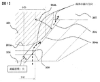
- FIG. It is a graph which shows the relationship between (PHI) d / (PHI) D and the fuel pressure of a seat surface front-end
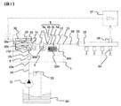
- FIG. 1 shows the overall configuration of a system that implements the present invention.
- a portion surrounded by a broken line in FIG. 1 shows a pump housing 1 of a high-pressure fuel supply pump, and a mechanism and parts shown in the broken line are integrally incorporated therein.
- the fuel in the fuel tank 20 is pumped up by the feed pump 21 and sent to the fuel inlet 10 a of the pump housing 1 through the suction pipe 28.
- the fuel that has passed through the fuel intake port 10a reaches the intake port 30a of the electromagnetic intake valve mechanism 30 that constitutes the variable capacity mechanism via the pressure pulsation reducing mechanism 9 and the intake passage 10c.
- the electromagnetic suction valve mechanism 30 includes an electromagnetic coil 30b, and in a state where the electromagnetic coil 30b is energized, the electromagnetic plunger 30c compresses the spring 33 and moves to the right in FIG. Maintained. At this time, the suction valve body 31 attached to the tip of the electromagnetic plunger 30c opens the suction port 32 leading to the pressurizing chamber 11 of the high-pressure fuel supply pump.
- the electromagnetic coil 30 b is not energized and there is no fluid differential pressure between the suction passage 10 c (suction port 30 a) and the pressurizing chamber 11, the suction valve body 31 is moved by the biasing force of the spring 33.
- the suction port 32 is urged in the valve closing direction (leftward in FIG. 1) to be closed, and this state is maintained.
- the suction valve body 31 is moved leftward in FIG. 1 by the urging force of the spring 33 that is constantly acting on the suction valve body 31 to close the suction port 32.
- the suction port 32 is closed, the fuel pressure in the pressurizing chamber 11 rises with the rise of the plunger 2 from this time.
- the fuel pressure in the pressurizing chamber 11 exceeds a pressure larger than the fuel pressure in the discharge port 13 by a predetermined value, the fuel remaining in the pressurizing chamber 11 is discharged via the discharge valve mechanism 8. High pressure discharge is performed and supplied to the common rail 23. This process is called a discharge process.
- the compression process of the plunger 2 includes a return process and a discharge process.
- the amount of high-pressure fuel discharged can be controlled by controlling the timing of releasing the energization of the electromagnetic coil 30c of the electromagnetic intake valve mechanism 30. If the timing of releasing the energization to the electromagnetic coil 30b is advanced, the ratio of the return process in the compression process is reduced and the ratio of the discharge process is increased. That is, the amount of fuel returned to the suction passage 10c (suction port 30a) is reduced and the amount of fuel discharged at high pressure is increased. On the other hand, if the timing of releasing the energization is delayed, the ratio of the return process in the compression process is increased and the ratio of the discharge process is decreased. That is, more fuel is returned to the suction passage 10c and less fuel is discharged at high pressure. The timing of releasing the energization is controlled by a command from the ECU.
- the ECU controls the timing of releasing the energization of the electromagnetic coil, whereby the amount of fuel discharged at a high pressure can be made the amount required by the internal combustion engine.
- a discharge valve mechanism 8 is provided on the outlet side of the pressurizing chamber 11 between the discharge port (discharge side pipe connection portion) 13.
- the discharge valve mechanism 8 includes a sheet member 8a, a discharge valve 8b, a discharge valve spring 8c, and a holding member (discharge valve stopper) 8d.
- the discharge valve 8b In a state where there is no fuel differential pressure between the pressurizing chamber 11 and the discharge port 13, the discharge valve 8b is pressed against the seat member 8a by the urging force of the discharge valve spring 8c and is in a closed state.
- the discharge valve 8b After the discharge valve 8b is opened, the operation is restricted when it comes into contact with the holding member 8d. Therefore, the stroke of the discharge valve 8b is appropriately determined by the holding member 8d. If the stroke is too large, the fuel discharged to the fuel discharge port 13 flows back into the pressurizing chamber 11 again due to the delay in closing the discharge valve 8b, so that the efficiency of the high-pressure pump decreases. . Further, when the discharge valve 8b repeats opening and closing movements, the holding member 8d guides the discharge valve so as to move only in the stroke direction. By configuring as described above, the discharge valve mechanism 8 becomes a check valve that restricts the flow direction of fuel.
- the fuel introduced to the fuel suction port 10a is pressurized to a required amount by the reciprocating motion of the plunger 2 in the pressurizing chamber 11 of the pump body 1, and the fuel discharge port 13 passes through the discharge valve mechanism 8.
- the common rail 23 which is a high-pressure pipe.
- the common rail 23 is provided with an injector 24 and a pressure sensor 26.
- the injectors 24 are mounted in accordance with the number of cylinders of the internal combustion engine, and the fuel is injected into the cylinders by operating the on-off valve according to the control signal of the ECU 27.
- the pump housing 1 is provided with a relief passage 300 that connects the discharge passage 12 and the suction passage 10c.
- the relief passage 300 restricts the flow of fuel in only one direction from the discharge passage 12 to the suction passage 10c.
- a valve mechanism 200 is provided.
- a pressurizing chamber 11 for pressurizing the fuel, a discharge valve mechanism 8 disposed on the downstream side of the pressurizing chamber 11, and fuel in the discharge passage 12 on the downstream side of the discharge valve mechanism 8 are returned to the suction passage 10c which is a low-pressure passage. And a relief valve mechanism.
- the fuel flow in the relief passage 300 may flow from the discharge passage 12 into the pressurizing chamber 11. That is, the relief valve mechanism 200 of this embodiment may return the fuel in the discharge passage 12 on the downstream side of the discharge valve mechanism 8 to the pressurizing chamber 11.
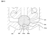
- FIG. 3 shows a cross section of the relief valve mechanism according to the first embodiment of the present invention.
- the relief valve mechanism 200 is formed to expand toward the pressurizing chamber 11 or the low-pressure passage (suction passage 10c) connected to the relief passage 208a and the relief passage 208a.
- a relief seat surface 204, and a relief valve body 201 that is positioned on the side of the pressure chamber 11 or the low-pressure passage (suction passage 10c) with respect to the relief seat surface 204 and is seated on the relief seat surface 204.
- the relief valve mechanism 200 includes a valve body retainer 202 that restrains the relief valve body 201, an elastic member 203 that urges the relief valve body 201 toward the discharge passage 12 (relief upstream side), an elastic member 203, and a valve body retainer 202.
- a housing 205 housed therein.
- the relief seat surface 204 has a seat portion 204a that engages with the relief valve body 201 to seal the fuel.
- On the upstream side of the relief valve body 201 there is a high pressure chamber 206 that is always in communication with the discharge passage 12, and on the downstream side of the relief valve body 201 is a pressure chamber 11 or a low pressure chamber 207 that is always in communication with the low pressure passage (suction passage 10c). It is formed.
- the relief passage 208 a is formed from the high pressure chamber 206 on the upstream side of the relief valve body 201 toward the relief seat surface 204.
- the relief valve body 201 is urged against the seat portion 204 a by the elastic member 203 against the pressure of the high-pressure fuel guided from the discharge flow path 12.
- the fluid force acting on the relief valve body 201 may exceed the urging force of the elastic member 203. Then, the relief valve body 201 leaves the seat portion 204a, the relief valve mechanism 200 is opened, and the relief passage is in a communicating state.
- the pressure in the high pressure chamber 206 decreases again, the urging force of the elastic member 203 exceeds the fluid force acting on the relief valve body 201, and the relief valve body 201 moves toward the seat portion 204a, Sit on the seat portion 204a.
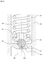
- FIG. 4 shows a sectional view of an example of the relief valve mechanism.
- FIG. 6 is an enlarged sectional view of the relief valve mechanism of FIG.
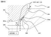
- the sheet surface front end 208 on the inner peripheral side of the relief sheet surface 204 is formed at a position close to the sheet portion 204a.
- the present inventors have intensively studied and found that cavitation and erosion occur at the front end 208 of the sheet surface according to the structure shown in FIG.
- FIG. 8 shows a state in which cavitation occurs at the front end 208 of the sheet surface.
- the relief valve body 201 is The seat 204a formed on the relief seat surface 204 is opened and the valve is opened, and the relief passage is in a communicating state. Then, the high-pressure fuel passes through the relief passage 208a from the high-pressure chamber 206, changes the direction of fuel flow at the seat surface front end portion 208, passes through the gap formed between the seat portion 204a and the relief valve body 201, and is relieved. It flows to the low pressure chamber 207 on the downstream side of the valve body 201.
- the cavitation bubbles 210 generated at the front end portion 208 of the sheet surface flow in the direction of the seat portion 204a due to the flow of fuel from the high pressure chamber 206 to the low pressure chamber 207, and away from the fluid separation portion that is at a low pressure.
- the cavitation bubble 210 collapses and a high impact force is generated.
- the impact force strikes the wall surface of the seat portion 204a, where cavitation and erosion occur. Therefore, in the following, the structure of this embodiment for preventing cavitation and erosion from occurring at the front end 208 of the relief valve mechanism will be described.
- FIG. 5 is a view for explaining the configuration of the relief valve mechanism of this embodiment.
- FIG. 7 shows an enlarged cross-sectional view of the relief valve mechanism of FIG.
- the sheet surface front end portion 208 is arranged at a position away from the sheet portion 204a.
- the seat surface front end portion 208 is disposed on the high pressure side relative to the high pressure side end portion 201 a of the relief valve body 201. That is, the intersection of the relief passage 208 and the relief sheet surface 204 is located on the discharge passage 12 side with respect to the end of the relief valve body on the discharge passage 12 side.
- the ratio obtained by ⁇ d / ⁇ D is obtained. It may be set to 0.6 or less. That is, the diameter ⁇ d of the relief passage 208 is formed to be 0.6 times or less than the sheet diameter ⁇ D of the relief sheet surface.
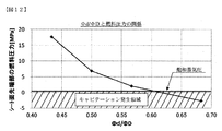
- FIG. 12 shows the relationship between ⁇ d / ⁇ D obtained by the fluid analysis simulation and the fuel pressure at the front end of the seat surface.
- the vertical axis represents the fuel pressure at the front end of the seat surface
- the horizontal axis represents the ratio ⁇ d / ⁇ D.
- Cavitation occurs when the fuel pressure at the front end of the seat surface is equal to or lower than the saturated vapor pressure shown in the figure. Therefore, the occurrence of cavitation can be suppressed by setting the ratio of ⁇ d / ⁇ D to 0.6 or less. . Or you may make it form so that the diameter of the relief channel
- FIG. Thereby, similarly to the above, the flow rate of fuel is small, the occurrence of fluid separation can be suppressed, and the generation of cavitation bubbles 210 can be suppressed.
- the relief sheet surface 204 is polished on the side of the pressurizing chamber 11 or the low pressure passage (suction passage 10c) from the intersection (sheet surface front end 208) of the relief passage 208 and the relief sheet surface 204. If the surface roughness of the sheet surface is poor, it is the same as the infinite number of edges formed on the sheet surface itself, and therefore fluid separation tends to occur. In this embodiment, the sheet surface is polished to suppress the occurrence of fluid separation on the sheet surface. In this embodiment, as shown in FIG. 5, the R portion is not formed at the intersection of the relief passage 208 and the relief sheet surface 204 (sheet surface front end portion 208), but these are intersected at a predetermined angle. ing.
- the formation of the R portion is high in manufacturing cost, and it is difficult to maintain the accuracy of the R portion in manufacturing. .
- the relief passage 208 is formed substantially in parallel with the expansion and contraction direction of the spring portion 203 that biases the relief valve body 201.
- the angle 204b between the relief passage 208a and the relief sheet surface 204 is formed so as to be inclined to 50 degrees or less. That is, the relief sheet surface 204 is formed so as to be inclined to the outer peripheral side by 50 degrees or less with respect to the relief passage 208.
- the seat surface front end portion 208 can be installed on the higher pressure side than the high pressure side end portion 201 a of the relief valve body 201.
- the intersection of the seat surface and the passage hole is installed at a position away from the seat portion, which is the smallest portion of the fuel passage area.
- the relief valve body 201 has a spherical shape.
- the relief valve body 201 does not necessarily have to be a spherical body, for example, a conical shape, a shape obtained by cutting the tip of the conical shape, or a portion that contacts the seat portion 204a. Only spherical may be sufficient.
- it is desirable that the sheet portion 204 a is disposed at a substantially central portion on the sheet surface 204. As a result, it is possible to obtain the operations and effects described above with reference to FIG.
- FIG. 9 shows a second embodiment of the present invention.
- a housing 205 surrounding the low-pressure chamber 207 existing downstream with respect to the relief valve body 201 and the seat portion 204 are integrated into a unit.
- a hole 214 is dug in the main body 211.
- the housing 205 and the seat portion 204a having an integral structure are formed as separate parts from the main body 211, and the housing 205 and the seat portion 204a having the integral structure are formed in a hole 214 dug into the main body 211. Is installed. If the relief valve mechanism of this configuration has the characteristics described in the first embodiment and the seat surface front end portion 208 is formed at a position away from the seat portion 204a, the effect described in the first embodiment is obtained.
- FIG. 10 shows a third embodiment of the present invention.
- a sheet member 215 is formed as a separate part from the main body 211, and the seat portion 204 a has a structure surrounding the high pressure chamber 206 on the upstream side, and is installed in a hole 214 dug into the main body 211. It is the composition which becomes. If the relief valve mechanism of this configuration has the characteristics described in the first embodiment and the seat surface front end portion 208 is formed at a position away from the seat portion 204a, the effect described in the first embodiment is obtained.
- FIG. 11 shows a fourth embodiment of the present invention.
- the main body body 211 is directly dug to form a relief sheet surface 204.
- the relief valve mechanism of this configuration has the characteristics described in the first embodiment and the seat surface front end portion 208 is formed at a position away from the seat portion 204a, the same effect as described in the first embodiment is obtained.
- Low pressure chamber 208 ... Seat surface tip, 208a ... Relief passage, 209 ... High speed vibration, 210 ... Cavitation bubbles, 211 ... body, 213 ... sheet portion, 214 ... hole, 215 ... sheet member.
Abstract
The purpose of the present invention is to suppress cavitation that occurs in a seat surface tip part when a valve body and a seat part collide. In a relief valve of a fuel pump, the point of intersection between the seat surface and a flow channel hole is formed in a position farther from the seat part comprising the seat surface and the valve body when the valve is closed, in order to suppress the occurrence of cavitation bubbles when the valve body is changed to let out high-pressure fuel.
Description
本発明は高圧燃料ポンプについて、特にリリーフ弁機構を備えた高圧燃料ポンプに関する。
The present invention relates to a high pressure fuel pump, and more particularly to a high pressure fuel pump provided with a relief valve mechanism.
特許文献1に記載の高圧ポンプは、高圧側から低圧側へ高圧液体をリリーフするリリーフ通路において、弁体と、弁体と係合して燃料をシートするシート部があり、前記シート部が本体ボディに対して別部品となっている。また、本体ボディに掘り込まれた穴に前記シート部が圧入されている構造において、弁体と弁体を付勢する弾性部材の間にスライダが設置されている。そして、前記スライダが摺動内壁に沿って開弁方向に摺動することにより、摺動経路が規制される。これにより、弾性部材の軸に対して傾いた応力がかからなくなり、リリーフ弁のリフト量を安定させ、スプリングの耐久性を向上させることが記載されている。
The high-pressure pump described in Patent Document 1 includes a valve body and a seat portion that engages with the valve body and seats fuel in a relief passage that relieves high-pressure liquid from a high-pressure side to a low-pressure side. It is a separate part for the body. In the structure in which the seat portion is press-fitted into a hole dug into the main body, a slider is installed between the valve body and an elastic member that urges the valve body. Then, the sliding path is regulated by sliding the slider in the valve opening direction along the sliding inner wall. Accordingly, it is described that stress inclined with respect to the axis of the elastic member is not applied, the lift amount of the relief valve is stabilized, and the durability of the spring is improved.
従来技術には次のような課題点があった。
The conventional technology has the following problems.
高圧燃料ポンプのリリーフ弁は、吐出圧が許容値を超えて高くなる異常圧の発生を抑制する機能がある。よって吐出圧が設定圧力を超えて高くなった場合、リリーフ弁の弁体が開弁し、高い圧力を逃がす。
The relief valve of the high-pressure fuel pump has a function to suppress the occurrence of abnormal pressure where the discharge pressure becomes higher than the allowable value. Therefore, when the discharge pressure becomes higher than the set pressure, the valve body of the relief valve opens and the high pressure is released.
吐出圧が許容値以下である条件を満たしているときは、弁体はシート部に着座して、燃料を完全にシールする必要がある。
When the condition that the discharge pressure is below the permissible value is satisfied, the valve body must be seated on the seat and the fuel must be completely sealed.
ここで弁体が開弁し、高い圧力を逃がす際の燃料通路の一部に、シート面の高圧側に、シート面と流路穴の交点がエッジになっていると、高圧の燃料を逃がす際にこのエッジ部にて流体剥離が発生することがある。そして、燃料の飽和蒸気圧以下になるとキャビテーション気泡が発生する。この発生したキャビテーション気泡が崩壊する際のエネルギーによりシート面が損傷するというキャビテーションエロージョンが発生する虞がある。この損傷が進行すると、弁体とシートの間に隙間が生じ燃料を完全にシールする事ができなくなる虞がある。
Here, when the valve element opens and part of the fuel passage when high pressure is released, the intersection of the seat surface and the passage hole is an edge on the high pressure side of the seat surface, high pressure fuel is released In some cases, fluid separation may occur at the edge portion. And when it becomes below the saturated vapor pressure of fuel, cavitation bubbles are generated. There is a risk that cavitation erosion may occur in which the sheet surface is damaged by energy generated when the generated cavitation bubbles collapse. When this damage progresses, there is a possibility that a gap is generated between the valve body and the seat and the fuel cannot be completely sealed.
そこで本発明では、リリーフ弁機構のシート面におけるキャビテーションエロージョンの発生を抑制し、信頼性の高いリリーフ弁機構を備えた高圧燃料ポンプを提供することを目的とする。
Therefore, an object of the present invention is to provide a high-pressure fuel pump having a highly reliable relief valve mechanism that suppresses the occurrence of cavitation erosion on the seat surface of the relief valve mechanism.
上記の課題を解決するために本発明においては、燃料を加圧する加圧室と、前記加圧室の下流側に配置される吐出弁と、前記吐出弁の下流側の吐出通路の燃料を前記加圧室、又は低圧通路に戻すリリーフ弁機構と、を備えた高圧燃料ポンプにおいて、前記リリーフ弁機構は、前記吐出通路と繋がって形成されるリリーフ通路と、前記リリーフ通路と繋がって、前記加圧室、又は前記低圧通路に向かって拡大して形成されるリリーフシート面と、前記リリーフシート面よりも加圧室側、又は低圧通路側に位置し、前記リリーフシート面に着座するリリーフ弁体と、を備え、前記リリーフ弁体の前記吐出通路の側の端部に対して、前記リリーフ通路と前記リリーフシート面との交点の方が前記吐出通路の側に位置することを特徴とする。
In order to solve the above problems, in the present invention, a pressurizing chamber for pressurizing fuel, a discharge valve disposed on the downstream side of the pressurizing chamber, and fuel in a discharge passage on the downstream side of the discharge valve In the high-pressure fuel pump comprising a pressurizing chamber or a relief valve mechanism for returning to the low-pressure passage, the relief valve mechanism is connected to the discharge passage and connected to the relief passage and connected to the relief passage. A relief seat surface that is enlarged toward the pressure chamber or the low-pressure passage, and a relief valve element that is positioned on the pressure chamber side or the low-pressure passage side of the relief seat surface and is seated on the relief seat surface The intersection of the relief passage and the relief sheet surface is located on the discharge passage side with respect to the end of the relief valve body on the discharge passage side.
本発明によれば、リリーフ弁機構のシート面におけるキャビテーションエロージョンの発生を抑制し、信頼性の高いリリーフ弁機構を備えた高圧燃料ポンプを提供することが可能となる。
According to the present invention, it is possible to provide a high-pressure fuel pump provided with a highly reliable relief valve mechanism by suppressing the occurrence of cavitation erosion on the seat surface of the relief valve mechanism.
以下、図を参照して、本発明の実施形態について、説明する。
Hereinafter, embodiments of the present invention will be described with reference to the drawings.
図1は、本発明を実施するシステムの全体構成を示す。図1において破線で囲まれた部分は、高圧燃料供給ポンプのポンプハウジング1を示し、この破線の中に示された機構と部品を、その中に一体に組み込んでいる。
FIG. 1 shows the overall configuration of a system that implements the present invention. A portion surrounded by a broken line in FIG. 1 shows a pump housing 1 of a high-pressure fuel supply pump, and a mechanism and parts shown in the broken line are integrally incorporated therein.
燃料タンク20中の燃料は、フィードポンプ21によって汲み上げられ、吸入配管28を通じてポンプハウジング1の燃料吸入口10aに送られる。燃料吸入口10aを通過した燃料は、圧力脈動低減機構9、吸入通路10cを介して、容量可変機構を構成する電磁吸入弁機構30の吸入ポート30aに至る。
The fuel in the fuel tank 20 is pumped up by the feed pump 21 and sent to the fuel inlet 10 a of the pump housing 1 through the suction pipe 28. The fuel that has passed through the fuel intake port 10a reaches the intake port 30a of the electromagnetic intake valve mechanism 30 that constitutes the variable capacity mechanism via the pressure pulsation reducing mechanism 9 and the intake passage 10c.
電磁吸入弁機構30は、電磁コイル30bを備え、この電磁コイル30bが通電されている状態で、電磁プランジャ30cは、ばね33を圧縮して図1における右方に移動した状態となり、その状態が維持される。このとき電磁プランジャ30cの先端に取付けられた吸入弁体31は、高圧燃料供給ポンプの加圧室11に通じる吸入口32を開く。電磁コイル30bが通電されていない状態であって、吸入通路10c(吸入ポート30a)と加圧室11との間に流体差圧がない時は、ばね33の付勢力により、吸入弁体31は、閉弁方向(図1における左方)に付勢されて吸入口32は閉じられた状態となって、この状態が維持される。
The electromagnetic suction valve mechanism 30 includes an electromagnetic coil 30b, and in a state where the electromagnetic coil 30b is energized, the electromagnetic plunger 30c compresses the spring 33 and moves to the right in FIG. Maintained. At this time, the suction valve body 31 attached to the tip of the electromagnetic plunger 30c opens the suction port 32 leading to the pressurizing chamber 11 of the high-pressure fuel supply pump. When the electromagnetic coil 30 b is not energized and there is no fluid differential pressure between the suction passage 10 c (suction port 30 a) and the pressurizing chamber 11, the suction valve body 31 is moved by the biasing force of the spring 33. The suction port 32 is urged in the valve closing direction (leftward in FIG. 1) to be closed, and this state is maintained.
後述する内燃機関のカムの回転により、プランジャ2が図1の下方に変位して吸入工程状態にある時は、加圧室11の容積は増加し、その中の燃料圧力は低下する。この工程において、加圧室11内の燃料圧力が吸入通路10c(吸入ポート30a)の圧力よりも低くなると、吸入弁体31には燃料の流体差圧による開弁力(吸入弁体31を図1の右方に変位させる力)が発生する。この開弁力により、吸入弁体31は、ばね33の付勢力に打ち勝って開弁し、吸入口32を開く。この状態にて、ECU27からの制御信号が電磁吸入弁機構30に印加されると電磁吸入弁30の電磁コイル30bに電流が流れ、磁気付勢力により電磁プランジャ30cがばね33を更に圧縮して、図1の右方に移動して、吸入口32を開いた状態を維持する。
When the plunger 2 is displaced downward in FIG. 1 due to the rotation of the cam of the internal combustion engine, which will be described later, and the suction chamber 11 is in the suction process state, the volume of the pressurizing chamber 11 increases and the fuel pressure therein decreases. In this step, when the fuel pressure in the pressurizing chamber 11 becomes lower than the pressure in the suction passage 10c (suction port 30a), the suction valve body 31 has a valve opening force (suction valve body 31 shown in FIG. 1) is generated. By this valve opening force, the suction valve body 31 overcomes the urging force of the spring 33 and opens to open the suction port 32. In this state, when a control signal from the ECU 27 is applied to the electromagnetic intake valve mechanism 30, an electric current flows through the electromagnetic coil 30b of the electromagnetic intake valve 30, and the electromagnetic plunger 30c further compresses the spring 33 by the magnetic biasing force. It moves to the right in FIG. 1 and maintains the state where the inlet 32 is open.
電磁吸入弁機構30に入力電圧の印加状態を維持したまま、プランジャ2が吸入工程から圧縮工程(下始点から上始点までの間の上昇工程)へと移行すると、電磁コイル30bへの通電状態が維持されているので、磁気付勢力は維持されて吸入弁体31は依然として開弁した状態を維持する。加圧室11の容積は、プランジャ2の圧縮運動に伴って減少するが、この状態では、一度加圧室11に吸入された燃料が、再び開弁状態の吸入弁体31と吸入口32との間を通過して吸入通路10c(吸入ポート30a)へと戻されるので、加圧室11の圧力が上昇することはない。この工程を、戻し工程という。
When the plunger 2 shifts from the suction process to the compression process (the ascending process from the lower start point to the upper start point) while maintaining the application state of the input voltage to the electromagnetic intake valve mechanism 30, the energized state of the electromagnetic coil 30b is changed. Since it is maintained, the magnetic urging force is maintained, and the suction valve body 31 still maintains the opened state. The volume of the pressurizing chamber 11 decreases with the compression movement of the plunger 2. In this state, the fuel once sucked into the pressurizing chamber 11 is once again opened into the intake valve body 31 and the inlet 32. Between the pressure chamber 11 and the suction passage 10c (suction port 30a), the pressure in the pressurizing chamber 11 does not increase. This process is called a return process.
戻し工程において、電磁コイル30bへの通電を断つと、電磁プランジャ30cに働いていた磁気付勢力は一定時間後(磁気的、機械的遅れ時間後)に消去される。そうすると、吸入弁体31に常時働いているばね33の付勢力により、吸入弁体31は図1において左方に移動されて吸入口32を閉じる。吸入口32が閉じると、この時から加圧室11内の燃料圧力は、プランジャ2の上昇と共に上昇する。そして、加圧室11内の燃料圧力が、吐出口13の燃料圧力よりも所定の値だけ大きい圧力を超えた時に、加圧室11に残っている燃料は、吐出弁機構8を介して、高圧吐出が行われてコモンレール23へと供給される。この工程を吐出工程という。上記のとおり、プランジャ2の圧縮工程は、戻し工程と吐出工程からなる。
In the returning step, when the energization to the electromagnetic coil 30b is cut off, the magnetic urging force acting on the electromagnetic plunger 30c is erased after a certain time (after the magnetic and mechanical delay time). Then, the suction valve body 31 is moved leftward in FIG. 1 by the urging force of the spring 33 that is constantly acting on the suction valve body 31 to close the suction port 32. When the suction port 32 is closed, the fuel pressure in the pressurizing chamber 11 rises with the rise of the plunger 2 from this time. When the fuel pressure in the pressurizing chamber 11 exceeds a pressure larger than the fuel pressure in the discharge port 13 by a predetermined value, the fuel remaining in the pressurizing chamber 11 is discharged via the discharge valve mechanism 8. High pressure discharge is performed and supplied to the common rail 23. This process is called a discharge process. As described above, the compression process of the plunger 2 includes a return process and a discharge process.
戻し工程中に、吸入通路10cへ戻された燃料により吸入通路には圧力脈動が発生するが、この圧力脈動は、吸入口10aから吸入配管28へ僅かに逆流するのみであり、燃料の戻しの大部分は圧力脈動低減機構9により吸収される。
During the returning process, the pressure pulsation is generated in the suction passage due to the fuel returned to the suction passage 10c, but this pressure pulsation only slightly flows backward from the suction port 10a to the suction pipe 28, and the fuel is returned. Most of the energy is absorbed by the pressure pulsation reducing mechanism 9.
電磁吸入弁機構30の電磁コイル30cへの通電解除のタイミングを制御することにより、吐出される高圧燃料の量を制御することができる。電磁コイル30bへの通電解除のタイミングを早くすれば、圧縮工程における戻し工程の割合を小さく、吐出工程の割合を大きくする。すなわち、吸入通路10c(吸入ポート30a)に戻される燃料を少なく、高圧吐出される燃料を多くする。これに対し、上記の通電解除のタイミングを遅くすれば、圧縮工程における戻し工程の割合を大きく、吐出工程の割合を小さくする。すなわち、吸入通路10cに戻される燃料を多く、高圧吐出される燃料を少なくする。上記の通電解除のタイミングは、ECUから指令により制御される。
The amount of high-pressure fuel discharged can be controlled by controlling the timing of releasing the energization of the electromagnetic coil 30c of the electromagnetic intake valve mechanism 30. If the timing of releasing the energization to the electromagnetic coil 30b is advanced, the ratio of the return process in the compression process is reduced and the ratio of the discharge process is increased. That is, the amount of fuel returned to the suction passage 10c (suction port 30a) is reduced and the amount of fuel discharged at high pressure is increased. On the other hand, if the timing of releasing the energization is delayed, the ratio of the return process in the compression process is increased and the ratio of the discharge process is decreased. That is, more fuel is returned to the suction passage 10c and less fuel is discharged at high pressure. The timing of releasing the energization is controlled by a command from the ECU.
以上のように、ECUが電磁コイルの通電解除のタイミングを制御することにより、高圧吐出される燃料量を、内燃機関が必要とする量とすることができる。
As described above, the ECU controls the timing of releasing the energization of the electromagnetic coil, whereby the amount of fuel discharged at a high pressure can be made the amount required by the internal combustion engine.
ポンプハウジング1内において、加圧室11の出口側には吐出口(吐出側配管接続部)13との間に吐出弁機構8が設けられる。吐出弁機構8は、シート部材8a、吐出弁8b、吐出弁ばね8c、保持部材(吐出弁ストッパー)8dからなる。加圧室11と吐出口13との間に燃料の差圧がない状態では、吐出弁8bは、吐出弁ばね8cによる付勢力でシート部材8aに圧着され閉弁状態となっている。加圧室11内の燃料圧力が、吐出口13の燃料圧力よりも所定の値だけ大きい圧力を超えた時に、吐出弁8bは吐出弁ばね8cに抗して開弁し、加圧室11内の燃料は吐出口13を経てコモンレール23へと吐出される。
In the pump housing 1, a discharge valve mechanism 8 is provided on the outlet side of the pressurizing chamber 11 between the discharge port (discharge side pipe connection portion) 13. The discharge valve mechanism 8 includes a sheet member 8a, a discharge valve 8b, a discharge valve spring 8c, and a holding member (discharge valve stopper) 8d. In a state where there is no fuel differential pressure between the pressurizing chamber 11 and the discharge port 13, the discharge valve 8b is pressed against the seat member 8a by the urging force of the discharge valve spring 8c and is in a closed state. When the fuel pressure in the pressurizing chamber 11 exceeds a pressure larger than the fuel pressure in the discharge port 13 by a predetermined value, the discharge valve 8b opens against the discharge valve spring 8c, and the pressure chamber 11 opens. The fuel is discharged to the common rail 23 through the discharge port 13.
吐出弁8bは開弁した後、保持部材8dと接触すると動作を制限される。そのゆえ、吐出弁8bのストロークは、保持部材8dによって適切に決定される。もし、ストロークが大きすぎると、吐出弁8bの閉じ遅れにより、燃料吐出口13へ吐出される燃料が、再び加圧室11内に逆流してしまうので、高圧ポンプとしての効率が低下してしまう。また、吐出弁8bが開弁と閉弁運動を繰り返す時に、吐出弁がストローク方向にのみ運動するように、保持部材8dによりガイドしている。以上のように構成することにより、吐出弁機構8は、燃料の流通方向を制限する逆止弁となる。
After the discharge valve 8b is opened, the operation is restricted when it comes into contact with the holding member 8d. Therefore, the stroke of the discharge valve 8b is appropriately determined by the holding member 8d. If the stroke is too large, the fuel discharged to the fuel discharge port 13 flows back into the pressurizing chamber 11 again due to the delay in closing the discharge valve 8b, so that the efficiency of the high-pressure pump decreases. . Further, when the discharge valve 8b repeats opening and closing movements, the holding member 8d guides the discharge valve so as to move only in the stroke direction. By configuring as described above, the discharge valve mechanism 8 becomes a check valve that restricts the flow direction of fuel.
こうして、燃料吸入口10aに導かれた燃料は、ポンプ本体1の加圧室11内にてプランジャ2の往復動によって必要な量が高圧に加圧され、吐出弁機構8を通じて、燃料吐出口13から高圧配管であるコモンレール23に圧送される。
Thus, the fuel introduced to the fuel suction port 10a is pressurized to a required amount by the reciprocating motion of the plunger 2 in the pressurizing chamber 11 of the pump body 1, and the fuel discharge port 13 passes through the discharge valve mechanism 8. To the common rail 23, which is a high-pressure pipe.
コモンレール23には、インジェクタ24と圧力センサ26が装着されている。インジェクタ24は、内燃機関の気筒数に合わせて装着されており、ECU27の制御信号により、開閉弁の動作をして、燃料をシリンダ内に噴射する。
The common rail 23 is provided with an injector 24 and a pressure sensor 26. The injectors 24 are mounted in accordance with the number of cylinders of the internal combustion engine, and the fuel is injected into the cylinders by operating the on-off valve according to the control signal of the ECU 27.
次に、インジェクタ24の故障等によりコモンレール23等の高圧部に異常高圧が発生した場合の、実施例1における燃料リリーフ動作について説明する。
Next, the fuel relief operation in the first embodiment when an abnormal high pressure occurs in the high pressure portion such as the common rail 23 due to a failure of the injector 24 or the like will be described.
ポンプハウジング1には、吐出通路12と吸入通路10cを連通するリリーフ通路300が設けられており、リリーフ通路300には燃料の流れを吐出通路12から吸入通路10cへの一方向のみに制限するリリーフ弁機構200が設けられている。燃料を加圧する加圧室11と、加圧室11の下流側に配置される吐出弁機構8と、吐出弁機構8の下流側の吐出通路12の燃料を低圧通路である吸入通路10cに戻すリリーフ弁機構と、を備えた。
The pump housing 1 is provided with a relief passage 300 that connects the discharge passage 12 and the suction passage 10c. The relief passage 300 restricts the flow of fuel in only one direction from the discharge passage 12 to the suction passage 10c. A valve mechanism 200 is provided. A pressurizing chamber 11 for pressurizing the fuel, a discharge valve mechanism 8 disposed on the downstream side of the pressurizing chamber 11, and fuel in the discharge passage 12 on the downstream side of the discharge valve mechanism 8 are returned to the suction passage 10c which is a low-pressure passage. And a relief valve mechanism.
また図2に示すように、リリーフ通路300の燃料の流れが吐出通路12から加圧室11内となる場合もある。すなわち、本実施例のリリーフ弁機構200は吐出弁機構8の下流側の吐出通路12の燃料を加圧室11に戻すものであっても良い。
In addition, as shown in FIG. 2, the fuel flow in the relief passage 300 may flow from the discharge passage 12 into the pressurizing chamber 11. That is, the relief valve mechanism 200 of this embodiment may return the fuel in the discharge passage 12 on the downstream side of the discharge valve mechanism 8 to the pressurizing chamber 11.
図3は、本発明の実施例1に係わるリリーフ弁機構の断面を示す。リリーフ弁機構200は、吐出通路12と繋がって形成されるリリーフ通路208aと、リリーフ通路208aと繋がって、加圧室11、又は低圧通路(吸入通路10c)の側に向かって拡大して形成されるリリーフシート面204と、リリーフシート面204よりも加圧室11、又は低圧通路(吸入通路10c)の側に位置し、リリーフシート面204に着座するリリーフ弁体201と、を備える。またリリーフ弁機構200は、リリーフ弁体201を押さえる弁体押さえ202、リリーフ弁体201を吐出通路12の側(リリーフ上流側)に付勢する弾性部材203、弾性部材203や弁体押さえ202を内部に収納するハウジング205と、を備える。
FIG. 3 shows a cross section of the relief valve mechanism according to the first embodiment of the present invention. The relief valve mechanism 200 is formed to expand toward the pressurizing chamber 11 or the low-pressure passage (suction passage 10c) connected to the relief passage 208a and the relief passage 208a. A relief seat surface 204, and a relief valve body 201 that is positioned on the side of the pressure chamber 11 or the low-pressure passage (suction passage 10c) with respect to the relief seat surface 204 and is seated on the relief seat surface 204. The relief valve mechanism 200 includes a valve body retainer 202 that restrains the relief valve body 201, an elastic member 203 that urges the relief valve body 201 toward the discharge passage 12 (relief upstream side), an elastic member 203, and a valve body retainer 202. A housing 205 housed therein.
リリーフシート面204はリリーフ弁体201と係合して燃料をシールするシート部204aを有する。リリーフ弁体201の上流側には吐出通路12と常に連通する高圧室206、リリーフ弁体201の下流側には加圧室11、又は低圧通路(吸入通路10c)と常に連通する低圧室207が形成される。リリーフ通路208aはリリーフ弁体201の上流側の高圧室206からリリーフシート面204に向かって形成される。リリーフ弁体201は、吐出流路12から導かれる高圧燃料の圧力に対抗して、弾性部材203により、シート部204aに付勢されている。
The relief seat surface 204 has a seat portion 204a that engages with the relief valve body 201 to seal the fuel. On the upstream side of the relief valve body 201, there is a high pressure chamber 206 that is always in communication with the discharge passage 12, and on the downstream side of the relief valve body 201 is a pressure chamber 11 or a low pressure chamber 207 that is always in communication with the low pressure passage (suction passage 10c). It is formed. The relief passage 208 a is formed from the high pressure chamber 206 on the upstream side of the relief valve body 201 toward the relief seat surface 204. The relief valve body 201 is urged against the seat portion 204 a by the elastic member 203 against the pressure of the high-pressure fuel guided from the discharge flow path 12.
吐出通路12の圧力が異常高圧となり、高圧室206の圧力が上昇すると、これによりリリーフ弁体201に作用する流体力が弾性部材203の付勢力を上回ることがある。すると、リリーフ弁体201はシート部204aを離れてリリーフ弁機構200が開弁し、リリーフ通路は連通状態になる。また、再び、高圧室206の圧力が低下すると、リリーフ弁体201に作用する流体力よりも弾性部材203の付勢力が上回り、リリーフ弁体201はシート部204aの側に向かって移動して、シート部204aに着座する。
When the pressure in the discharge passage 12 becomes abnormally high and the pressure in the high pressure chamber 206 increases, the fluid force acting on the relief valve body 201 may exceed the urging force of the elastic member 203. Then, the relief valve body 201 leaves the seat portion 204a, the relief valve mechanism 200 is opened, and the relief passage is in a communicating state. When the pressure in the high pressure chamber 206 decreases again, the urging force of the elastic member 203 exceeds the fluid force acting on the relief valve body 201, and the relief valve body 201 moves toward the seat portion 204a, Sit on the seat portion 204a.
図4にリリーフ弁機構の一例の断面図を示す。また図6はこの図4のリリーフ弁機構の断面拡大図を示している。この図4、及び図6の構造ではリリーフシート面204の内周側のシート面先端部208が、シート部204aから近い位置に形成されている。しかしながら、本発明者らは鋭意検討の末、この図4に示す構造によればシート面先端部208でキャビテーション、またエロージョンが発生してしまうことを突き止めたものである。
Fig. 4 shows a sectional view of an example of the relief valve mechanism. FIG. 6 is an enlarged sectional view of the relief valve mechanism of FIG. In the structure of FIGS. 4 and 6, the sheet surface front end 208 on the inner peripheral side of the relief sheet surface 204 is formed at a position close to the sheet portion 204a. However, the present inventors have intensively studied and found that cavitation and erosion occur at the front end 208 of the sheet surface according to the structure shown in FIG.
図8にシート面先端部208でキャビテーションが発生する様子を示す。
FIG. 8 shows a state in which cavitation occurs at the front end 208 of the sheet surface.
上記したように吐出通路12の圧力が異常高圧となり、高圧室206の圧力が上昇し、これによりリリーフ弁体201に採用する流体力が弾性部材203の付勢力を上回ると、リリーフ弁体201はリリーフシート面204に形成されたシート部204aを離れて開弁し、リリーフ通路は連通状態となる。すると、高圧の燃料が高圧室206からリリーフ通路208aを通って、シート面先端部208で燃料の流れる向きが変わって、シート部204aとリリーフ弁体201に間に生じた隙間を通って、リリーフ弁体201の下流側の低圧室207へと流れる。
As described above, when the pressure in the discharge passage 12 becomes abnormally high and the pressure in the high pressure chamber 206 increases, and the fluid force employed in the relief valve body 201 exceeds the urging force of the elastic member 203, the relief valve body 201 is The seat 204a formed on the relief seat surface 204 is opened and the valve is opened, and the relief passage is in a communicating state. Then, the high-pressure fuel passes through the relief passage 208a from the high-pressure chamber 206, changes the direction of fuel flow at the seat surface front end portion 208, passes through the gap formed between the seat portion 204a and the relief valve body 201, and is relieved. It flows to the low pressure chamber 207 on the downstream side of the valve body 201.
この高圧な燃料が流れる際に、燃料はシート面先端部208で急激に流れる方向が変わるために、流体剥離が発生し、一般に圧力の小さくなる流体剥離部の燃料の圧力は飽和蒸気圧以下になってキャビテーション気泡210が発生する。
When this high-pressure fuel flows, the direction in which the fuel flows suddenly changes at the front end portion 208 of the seat surface, so fluid separation occurs, and the pressure of the fuel in the fluid separation portion where the pressure generally decreases is below the saturated vapor pressure. Thus, cavitation bubbles 210 are generated.
シート面先端部208で発生したキャビテーション気泡210は、高圧室206から低圧室207へと向かう燃料の流れにより、シート部204a方向へと流れ、低圧である流体剥離部から離れることによりキャビテーション気泡210の周りの燃料圧力が飽和蒸気圧以上に回復するときにキャビテーション気泡210が崩壊して高い衝撃力が発生する。本衝撃力がシート部204aの壁面を叩き、そこでキャビテーション、そしてエロージョンが発生する。そこで以下においてはリリーフ弁機構のシート面先端部208でキャビテーション、またエロージョンが発生するのを防止する本実施例の構造について説明する。
The cavitation bubbles 210 generated at the front end portion 208 of the sheet surface flow in the direction of the seat portion 204a due to the flow of fuel from the high pressure chamber 206 to the low pressure chamber 207, and away from the fluid separation portion that is at a low pressure. When the surrounding fuel pressure recovers above the saturated vapor pressure, the cavitation bubble 210 collapses and a high impact force is generated. The impact force strikes the wall surface of the seat portion 204a, where cavitation and erosion occur. Therefore, in the following, the structure of this embodiment for preventing cavitation and erosion from occurring at the front end 208 of the relief valve mechanism will be described.
図5は本実施例のリリーフ弁機構の構成を説明するための図である。また図7は図5のリリーフ弁機構の断面拡大図を示している。図7に示すように本実施例ではシート面先端部208をシート部204aよりも離れた位置に配置するようにしている。具体的にはシート面先端部208をリリーフ弁体201の高圧側端部201aよりも高圧側に配置する。すなわち、リリーフ弁体の吐出通路12の側の端部に対して、リリーフ通路208とリリーフシート面204との交点の方が吐出通路12の側に位置する。
FIG. 5 is a view for explaining the configuration of the relief valve mechanism of this embodiment. FIG. 7 shows an enlarged cross-sectional view of the relief valve mechanism of FIG. As shown in FIG. 7, in the present embodiment, the sheet surface front end portion 208 is arranged at a position away from the sheet portion 204a. Specifically, the seat surface front end portion 208 is disposed on the high pressure side relative to the high pressure side end portion 201 a of the relief valve body 201. That is, the intersection of the relief passage 208 and the relief sheet surface 204 is located on the discharge passage 12 side with respect to the end of the relief valve body on the discharge passage 12 side.
これにより、高圧な燃料が流れる際に、燃料はシート面先端部208で急激に流れる方向が変わるが、シート面先端部208とリリーフ弁体201との隙間が大きく取れるために、十分な燃料流路面積が確保できる。したがって、燃料の流速が小さく、流体剥離発生が抑制できることより、流体剥離部の燃料の圧力は飽和蒸気圧以下とはならない。よって、キャビテーション気泡210が発生するのを抑制でき、信頼性の高いリリーフ弁機構とすることが可能である。
As a result, when high-pressure fuel flows, the direction in which the fuel flows suddenly changes at the seat surface front end portion 208. However, since a large gap is formed between the seat surface front end portion 208 and the relief valve body 201, sufficient fuel flow is achieved. Road area can be secured. Therefore, since the flow rate of the fuel is small and the occurrence of fluid separation can be suppressed, the fuel pressure in the fluid separation portion does not become equal to or lower than the saturated vapor pressure. Therefore, generation | occurrence | production of the cavitation bubble 210 can be suppressed and it can be set as a highly reliable relief valve mechanism.
またリリーフ弁体201のシート部204aとの接触部(シール部)が球状である場合の直径をΦD、リリーフ通路208aのシート面先端部208の直径をΦdとすると、Φd/ΦDで求まる比率を0.6以下とするようにしても良い。つまり、リリーフシート面のシート径ΦDに対して、リリーフ通路208の径Φdが0.6倍以下で形成されるようにするものである。これにより、燃料の流速が小さく、流体剥離発生が抑制でき、キャビテーション気泡210の発生が抑制できる事を流体解析シミュレーションで確認することができた。図12に流体解析シミュレーションにより得られたΦd/ΦDとシート面先端部の燃料圧力の関係性を示す。縦軸にシート面先端部の燃料圧力、横軸にΦd/ΦDの比率をとる。シート面先端部の燃料圧力が図に示す飽和蒸気圧以下となることでキャビテーションが発生するため、Φd/ΦDの比率を0.6以下とすることでキャビテーションの発生を抑制することが可能となる。あるいは、リリーフ弁体201の径に対して、リリーフ通路208の径が半分以下となるように形成するようにしても良い。これにより、上記と同様に燃料の流速が小さく、流体剥離発生が抑制でき、キャビテーション気泡210の発生が抑制できる。
Further, assuming that the diameter when the contact portion (seal portion) of the relief valve body 201 with the seat portion 204a is spherical is ΦD, and the diameter of the front end portion 208 of the relief passage 208a is Φd, the ratio obtained by Φd / ΦD is obtained. It may be set to 0.6 or less. That is, the diameter Φd of the relief passage 208 is formed to be 0.6 times or less than the sheet diameter ΦD of the relief sheet surface. As a result, it was confirmed by fluid analysis simulation that the flow rate of fuel is small, the occurrence of fluid separation can be suppressed, and the generation of cavitation bubbles 210 can be suppressed. FIG. 12 shows the relationship between Φd / ΦD obtained by the fluid analysis simulation and the fuel pressure at the front end of the seat surface. The vertical axis represents the fuel pressure at the front end of the seat surface, and the horizontal axis represents the ratio Φd / ΦD. Cavitation occurs when the fuel pressure at the front end of the seat surface is equal to or lower than the saturated vapor pressure shown in the figure. Therefore, the occurrence of cavitation can be suppressed by setting the ratio of Φd / ΦD to 0.6 or less. . Or you may make it form so that the diameter of the relief channel | path 208 may become half or less with respect to the diameter of the relief valve body 201. FIG. Thereby, similarly to the above, the flow rate of fuel is small, the occurrence of fluid separation can be suppressed, and the generation of cavitation bubbles 210 can be suppressed.
ここで、リリーフシート面204は、リリーフ通路208とリリーフシート面204との交点(シート面先端部208)から加圧室11、又は低圧通路(吸入通路10c)の側において研磨されている。
シート面の面粗さが悪いとシート面自体に無数のエッジが形成されていることと同様であるため、流体剥離が発生しやすくなる。本実施例ではシート面での流体剥離発生を抑制するためにシート面に研磨を行っている。本実施例では図5に示すようにリリーフ通路208とリリーフシート面204との交点(シート面先端部208)にはR部が形成されることなく、これらが所定の角度で交差して形成されている。シート面先端部208にR部を設けることでキャビテーション抑制を図ることも可能であるが、このR部の形成は製造コストが高く、また、製造上、R部の精度を保つのが困難である。これに対して本実施例では、上記のようにR部の形成が必要でなく、容易にキャビテーション抑制を図る構造とすることができるので、製造コストを抑え、かつ容易に製造することが可能である。 Here, therelief sheet surface 204 is polished on the side of the pressurizing chamber 11 or the low pressure passage (suction passage 10c) from the intersection (sheet surface front end 208) of the relief passage 208 and the relief sheet surface 204.
If the surface roughness of the sheet surface is poor, it is the same as the infinite number of edges formed on the sheet surface itself, and therefore fluid separation tends to occur. In this embodiment, the sheet surface is polished to suppress the occurrence of fluid separation on the sheet surface. In this embodiment, as shown in FIG. 5, the R portion is not formed at the intersection of therelief passage 208 and the relief sheet surface 204 (sheet surface front end portion 208), but these are intersected at a predetermined angle. ing. Although it is possible to suppress cavitation by providing the R portion at the front end portion 208 of the sheet surface, the formation of the R portion is high in manufacturing cost, and it is difficult to maintain the accuracy of the R portion in manufacturing. . On the other hand, in this embodiment, it is not necessary to form the R portion as described above, and it is possible to easily reduce the cavitation, so that the manufacturing cost can be suppressed and the manufacturing can be easily performed. is there.
シート面の面粗さが悪いとシート面自体に無数のエッジが形成されていることと同様であるため、流体剥離が発生しやすくなる。本実施例ではシート面での流体剥離発生を抑制するためにシート面に研磨を行っている。本実施例では図5に示すようにリリーフ通路208とリリーフシート面204との交点(シート面先端部208)にはR部が形成されることなく、これらが所定の角度で交差して形成されている。シート面先端部208にR部を設けることでキャビテーション抑制を図ることも可能であるが、このR部の形成は製造コストが高く、また、製造上、R部の精度を保つのが困難である。これに対して本実施例では、上記のようにR部の形成が必要でなく、容易にキャビテーション抑制を図る構造とすることができるので、製造コストを抑え、かつ容易に製造することが可能である。 Here, the
If the surface roughness of the sheet surface is poor, it is the same as the infinite number of edges formed on the sheet surface itself, and therefore fluid separation tends to occur. In this embodiment, the sheet surface is polished to suppress the occurrence of fluid separation on the sheet surface. In this embodiment, as shown in FIG. 5, the R portion is not formed at the intersection of the
なお、リリーフ通路208はリリーフ弁体201を付勢するばね部203の伸縮方向と略平行に形成されている。そして、リリーフ通路208aとのリリーフシート面204との角度204bは、50度以下に傾斜する様に形成する。すなわち、リリーフ通路208に対してリリーフシート面204は外周側に50度以下で傾斜するように形成される。これにより、シート面先端部208をリリーフ弁体201の高圧側端部201aよりも、より高圧側に設置する事ができる。よって、高圧な燃料が流れる際に、燃料はシート面先端部208で急激に流れる方向が変わるが、シート面先端部208とリリーフ弁体201との隙間が大きく取れるために、十分な燃料流路面積が確保できる。したがって、燃料の流速が小さく、流体剥離発生が抑制できることより、流体剥離部の燃料の圧力は飽和蒸気圧以下とはならずキャビテーション気泡210発生を抑制できる。
Note that the relief passage 208 is formed substantially in parallel with the expansion and contraction direction of the spring portion 203 that biases the relief valve body 201. The angle 204b between the relief passage 208a and the relief sheet surface 204 is formed so as to be inclined to 50 degrees or less. That is, the relief sheet surface 204 is formed so as to be inclined to the outer peripheral side by 50 degrees or less with respect to the relief passage 208. Thereby, the seat surface front end portion 208 can be installed on the higher pressure side than the high pressure side end portion 201 a of the relief valve body 201. Therefore, when the high-pressure fuel flows, the direction in which the fuel flows suddenly changes at the seat surface front end portion 208, but a sufficient gap between the seat surface front end portion 208 and the relief valve body 201 can be obtained. An area can be secured. Therefore, since the flow rate of the fuel is small and the occurrence of fluid separation can be suppressed, the fuel pressure in the fluid separation portion does not become equal to or lower than the saturated vapor pressure, and the generation of cavitation bubbles 210 can be suppressed.
以上の通り、本実施例においては、開弁時の高圧の燃料を逃がす際に、燃料の流路面積最小部である前記シート部から離れた位置にシート面と流路穴の交点を設置する。これにより、より広い燃料流路が確保できるために、流体剥離する可能性のあるエッジ部の流速を下げることができる。したがってエッジ部の圧力が飽和蒸気圧以下に低下する可能性が抑制され、キャビテーション気泡の発生を低減できるため、より信頼性の高いリリーフ弁機構を供給できる。よって、キャビテーションエロージョンの発生を抑制することができるため、弁体がシート部に着座した状態の時に、燃料を完全にシールすることができる。
As described above, in this embodiment, when high-pressure fuel is released when the valve is opened, the intersection of the seat surface and the passage hole is installed at a position away from the seat portion, which is the smallest portion of the fuel passage area. . Thereby, since a wider fuel flow path can be ensured, the flow velocity of the edge part that may cause fluid separation can be reduced. Therefore, the possibility that the pressure at the edge portion falls below the saturated vapor pressure is suppressed, and the generation of cavitation bubbles can be reduced, so that a more reliable relief valve mechanism can be supplied. Therefore, since the occurrence of cavitation erosion can be suppressed, the fuel can be completely sealed when the valve body is seated on the seat portion.
なお、図7ではリリーフ弁体201は球体形状であるが、リリーフ弁体201は必ずしも球体である必要は無く例えば円錐形状、もしくは円錐形状の先端をカットした形状、もしくはシート部204aと接触する部分のみ球状でも良い。なお、その場合にも図5に示すようにシート部204aはシート面204において略中央部に配置されることが望ましい。これにより、図5について説明した上記の作用、効果を得ることが可能である。
In FIG. 7, the relief valve body 201 has a spherical shape. However, the relief valve body 201 does not necessarily have to be a spherical body, for example, a conical shape, a shape obtained by cutting the tip of the conical shape, or a portion that contacts the seat portion 204a. Only spherical may be sufficient. In this case as well, as shown in FIG. 5, it is desirable that the sheet portion 204 a is disposed at a substantially central portion on the sheet surface 204. As a result, it is possible to obtain the operations and effects described above with reference to FIG.
図9に本発明の第2の実施例を示す。前記リリーフ弁体201に対して下流に存在する低圧室207を囲むハウジング205と前記シート部204が一体の構造となってユニット化されている。本体ボディ211に穴214が掘り込まれている。一体構造となっているハウジング205とシート部204aは、本体ボディ211に対して別部品で形成されており、本体ボディ211に掘り込まれた穴214に、前記一体構造のハウジング205とシート部204aが設置されている。本構成のリリーフ弁機構において、実施例1に記載の特徴を持ち、シート面先端部208がシート部204aから離れた位置に形成されていれば、実施例1に記載の効果を有する。
FIG. 9 shows a second embodiment of the present invention. A housing 205 surrounding the low-pressure chamber 207 existing downstream with respect to the relief valve body 201 and the seat portion 204 are integrated into a unit. A hole 214 is dug in the main body 211. The housing 205 and the seat portion 204a having an integral structure are formed as separate parts from the main body 211, and the housing 205 and the seat portion 204a having the integral structure are formed in a hole 214 dug into the main body 211. Is installed. If the relief valve mechanism of this configuration has the characteristics described in the first embodiment and the seat surface front end portion 208 is formed at a position away from the seat portion 204a, the effect described in the first embodiment is obtained.
図10に本発明の第3の実施例を示す。シート部材215が本体ボディ211に対して別部品で形成されており、本シート部204aは上流側の高圧室206を囲む構造となっており、本体ボディ211に掘り込まれた穴214に設置される構成となっている。本構成のリリーフ弁機構において、実施例1に記載の特徴を持ち、シート面先端部208がシート部204aから離れた位置に形成されていれば、実施例1に記載の効果を有する。
FIG. 10 shows a third embodiment of the present invention. A sheet member 215 is formed as a separate part from the main body 211, and the seat portion 204 a has a structure surrounding the high pressure chamber 206 on the upstream side, and is installed in a hole 214 dug into the main body 211. It is the composition which becomes. If the relief valve mechanism of this configuration has the characteristics described in the first embodiment and the seat surface front end portion 208 is formed at a position away from the seat portion 204a, the effect described in the first embodiment is obtained.
図11に本発明の第4の実施例を示す。本体ボディ211を直接、掘り込んでリリーフシート面204が形成されている。
FIG. 11 shows a fourth embodiment of the present invention. The main body body 211 is directly dug to form a relief sheet surface 204.
本構成のリリーフ弁機構において、実施例1に記載の特徴を持ち、シート面先端部208がシート部204aから離れた位置に形成されていれば、実施例1に記載の同じ効果を有する。
If the relief valve mechanism of this configuration has the characteristics described in the first embodiment and the seat surface front end portion 208 is formed at a position away from the seat portion 204a, the same effect as described in the first embodiment is obtained.
1…ポンプハウジング、2…プランジャ、8…吐出弁機構、9…圧力脈動低減機構、10c…吸入通路、11…加圧室、12…吐出通路、20…燃料タンク、23…コモンレール、24…インジェクタ、26…圧力センサ、30…電磁吸入弁機構、200…リリーフ弁機構、201…リリーフ弁体、201a・・・リリーフ弁体の高圧側端部、202…弁体押さえ、203…弾性部材、204…リリーフシート面204a・・・シート部、204b…角度、205…ハウジング、206…高圧室、207…低圧室、208…シート面先端部、208a・・・リリーフ通路、209…高速振動、210…キャビテーション気泡、211…本体ボディ、213…シート部、214…穴、215…シート部材。
DESCRIPTION OF SYMBOLS 1 ... Pump housing, 2 ... Plunger, 8 ... Discharge valve mechanism, 9 ... Pressure pulsation reduction mechanism, 10c ... Suction passage, 11 ... Pressurization chamber, 12 ... Discharge passage, 20 ... Fuel tank, 23 ... Common rail, 24 ... Injector , 26 ... Pressure sensor, 30 ... Electromagnetic suction valve mechanism, 200 ... Relief valve mechanism, 201 ... Relief valve body, 201a ... High pressure side end of the relief valve body, 202 ... Valve body presser, 203 ... Elastic member, 204 ... Relief sheet surface 204a ... Sheet part, 204b ... Angle, 205 ... Housing, 206 ... High pressure chamber, 207 ... Low pressure chamber, 208 ... Seat surface tip, 208a ... Relief passage, 209 ... High speed vibration, 210 ... Cavitation bubbles, 211 ... body, 213 ... sheet portion, 214 ... hole, 215 ... sheet member.
Claims (6)
- 燃料を加圧する加圧室と、前記加圧室の下流側に配置される吐出弁と、前記吐出弁の下流側の吐出通路の燃料を前記加圧室、又は低圧通路に戻すリリーフ弁機構と、を備えた高圧燃料ポンプにおいて、前記リリーフ弁機構は、前記吐出通路と繋がって形成されるリリーフ通路と、前記リリーフ通路と繋がって、前記加圧室、又は前記低圧通路に向かって拡大して形成されるリリーフシート面と、前記リリーフシート面よりも加圧室側、又は低圧通路側に位置し、前記リリーフシート面に着座するリリーフ弁体と、を備え、前記リリーフ弁体の前記吐出通路の側の端部に対して、前記リリーフ通路と前記リリーフシート面との交点の方が前記吐出通路の側に位置することを特徴とする高圧燃料ポンプ。 A pressurizing chamber for pressurizing fuel; a discharge valve disposed downstream of the pressurizing chamber; and a relief valve mechanism for returning fuel in a discharge passage downstream of the discharge valve to the pressurizing chamber or low-pressure passage. The relief valve mechanism is connected to the relief passage and connected to the relief passage, and is expanded toward the pressurizing chamber or the low pressure passage. A relief seat surface formed, and a relief valve body that is positioned closer to the pressure chamber side or the low-pressure passage side than the relief seat surface and is seated on the relief seat surface, the discharge passage of the relief valve body The high-pressure fuel pump is characterized in that the intersection of the relief passage and the relief seat surface is located on the discharge passage side with respect to the end portion on the side of the discharge passage.
- 燃料を加圧する加圧室と、前記加圧室の下流側に配置される吐出弁と、前記吐出弁の下流側の吐出通路の燃料を前記加圧室、又は低圧通路に戻すリリーフ弁機構と、を備えた高圧燃料ポンプにおいて、前記リリーフ弁機構は、前記吐出通路と繋がって形成されるリリーフ通路と、前記リリーフ通路と繋がって、前記加圧室、又は前記低圧通路に向かって拡大して形成されるリリーフシート面と、前記リリーフシート面よりも加圧室側、又は低圧通路側に位置し、前記リリーフシート面に着座するリリーフ弁体と、を備え、前記リリーフシート面のシート径に対して、前記リリーフ通路の径が0.6倍以下で形成されることを特徴とする高圧燃料ポンプ。 A pressurizing chamber for pressurizing fuel; a discharge valve disposed downstream of the pressurizing chamber; and a relief valve mechanism for returning fuel in a discharge passage downstream of the discharge valve to the pressurizing chamber or low-pressure passage. The relief valve mechanism is connected to the relief passage and connected to the relief passage, and is expanded toward the pressurizing chamber or the low pressure passage. A relief seat surface to be formed, and a relief valve body positioned on the pressure chamber side or the low pressure passage side from the relief seat surface and seated on the relief seat surface, and the seat diameter of the relief seat surface On the other hand, the high-pressure fuel pump is characterized in that the diameter of the relief passage is 0.6 times or less.
- 燃料を加圧する加圧室と、前記加圧室の下流側に配置される吐出弁と、前記吐出弁の下流側の吐出通路の燃料を前記加圧室、又は低圧通路に戻すリリーフ弁機構と、を備えた高圧燃料ポンプにおいて、前記リリーフ弁機構は、前記吐出通路と繋がって形成されるリリーフ通路と、前記リリーフ通路と繋がって、前記加圧室、又は前記低圧通路に向かって拡大して形成されるリリーフシート面と、前記リリーフシート面よりも加圧室側、又は低圧通路側に位置し、前記リリーフシート面に着座するリリーフ弁体と、を備え、前記リリーフ弁体の径に対して、前記リリーフ通路の径が半分以下で形成されることを特徴とする高圧燃料ポンプ。 A pressurizing chamber for pressurizing fuel; a discharge valve disposed downstream of the pressurizing chamber; and a relief valve mechanism for returning fuel in a discharge passage downstream of the discharge valve to the pressurizing chamber or low-pressure passage. The relief valve mechanism is connected to the relief passage and connected to the relief passage, and is expanded toward the pressurizing chamber or the low pressure passage. A relief seat surface that is formed, and a relief valve body that is positioned on the pressure chamber side or the low pressure passage side of the relief seat surface and is seated on the relief seat surface, the diameter of the relief valve body The relief passage is formed so that the diameter of the relief passage is less than half.
- 請求項1~3の何れかに記載の高圧燃料ポンプにおいて、前記リリーフシート面は、前記リリーフ通路と前記リリーフシート面との交点から加圧室側、又は低圧通路側において研磨されることを特徴とする高圧燃料ポンプ。 The high-pressure fuel pump according to any one of claims 1 to 3, wherein the relief seat surface is polished on the pressurizing chamber side or the low-pressure passage side from the intersection of the relief passage and the relief seat surface. And high pressure fuel pump.
- 請求項1に記載の高圧燃料ポンプにおいて、前記リリーフ通路と前記リリーフシート面との交点はR部が形成されることなく、所定の角度で交差して形成されることを特徴とする高圧燃料ポンプ。 2. The high-pressure fuel pump according to claim 1, wherein the intersection between the relief passage and the relief seat surface is formed by intersecting at a predetermined angle without forming an R portion. .
- 請求項1に記載の高圧燃料ポンプにおいて、前記リリーフ通路は前記リリーフ弁体を付勢するばね部の伸縮方向と略平行に形成され、前記リリーフ通路に対して前記リリーフシート面は外周側に50度以下で傾斜するように形成されることを特徴とするバルブ機構。 2. The high-pressure fuel pump according to claim 1, wherein the relief passage is formed substantially in parallel with an expansion / contraction direction of a spring portion that urges the relief valve body, and the relief seat surface is arranged on the outer peripheral side with respect to the relief passage. A valve mechanism formed so as to be inclined at a degree or less.
Priority Applications (4)
| Application Number | Priority Date | Filing Date | Title |
|---|---|---|---|
| EP16792480.2A EP3296558B1 (en) | 2015-05-12 | 2016-04-15 | High-pressure fuel pump |
| JP2017517840A JP6507235B2 (en) | 2015-05-12 | 2016-04-15 | High pressure fuel pump |
| US15/566,060 US10253741B2 (en) | 2015-05-12 | 2016-04-15 | High-pressure fuel pump |
| CN201680026869.0A CN107532555B (en) | 2015-05-12 | 2016-04-15 | High-pressure fuel pump |
Applications Claiming Priority (2)
| Application Number | Priority Date | Filing Date | Title |
|---|---|---|---|
| JP2015-096996 | 2015-05-12 | ||
| JP2015096996 | 2015-05-12 |
Publications (1)
| Publication Number | Publication Date |
|---|---|
| WO2016181755A1 true WO2016181755A1 (en) | 2016-11-17 |
Family
ID=57248723
Family Applications (1)
| Application Number | Title | Priority Date | Filing Date |
|---|---|---|---|
| PCT/JP2016/062050 WO2016181755A1 (en) | 2015-05-12 | 2016-04-15 | High-pressure fuel pump |
Country Status (5)
| Country | Link |
|---|---|
| US (1) | US10253741B2 (en) |
| EP (1) | EP3296558B1 (en) |
| JP (1) | JP6507235B2 (en) |
| CN (1) | CN107532555B (en) |
| WO (1) | WO2016181755A1 (en) |
Cited By (5)
| Publication number | Priority date | Publication date | Assignee | Title |
|---|---|---|---|---|
| WO2019097990A1 (en) * | 2017-11-15 | 2019-05-23 | 日立オートモティブシステムズ株式会社 | Relief valve mechanism and fuel supply pump comprising same |
| WO2019166136A1 (en) * | 2018-02-27 | 2019-09-06 | Robert Bosch Gmbh | Pressure-limiting valve |
| JP7089399B2 (en) | 2018-04-27 | 2022-06-22 | 日立Astemo株式会社 | Manufacturing method of fuel supply pump and fuel supply pump |
| US20220252030A1 (en) * | 2019-07-19 | 2022-08-11 | Robert Bosch Gmbh | High-Pressure Fuel Pump |
| WO2023032253A1 (en) * | 2021-09-03 | 2023-03-09 | 日立Astemo株式会社 | Fuel pump |
Citations (8)
| Publication number | Priority date | Publication date | Assignee | Title |
|---|---|---|---|---|
| JPS55157163U (en) * | 1979-04-27 | 1980-11-12 | ||
| JP2005214303A (en) * | 2004-01-29 | 2005-08-11 | Aisin Seiki Co Ltd | Relief valve |
| JP2007056989A (en) * | 2005-08-24 | 2007-03-08 | Denso Corp | Fluid control valve and its manufacturing method |
| JP2007533882A (en) * | 2003-11-25 | 2007-11-22 | ローベルト ボツシユ ゲゼルシヤフト ミツト ベシユレンクテル ハフツング | Valves for high-pressure pumps of fuel injection devices, especially for internal combustion engines |
| JP2011132941A (en) * | 2009-11-26 | 2011-07-07 | Nippon Soken Inc | Pressure control valve |
| JP2011220195A (en) * | 2010-04-08 | 2011-11-04 | Nippon Soken Inc | Device for inspecting pressure holding valve and method of inspecting the same |
| JP2013241835A (en) * | 2012-05-17 | 2013-12-05 | Nippon Soken Inc | Relief valve for high-pressure fuel pump |
| JP2014043820A (en) * | 2012-08-28 | 2014-03-13 | Denso Corp | High pressure fuel control device |
Family Cites Families (19)
| Publication number | Priority date | Publication date | Assignee | Title |
|---|---|---|---|---|
| JP2000145591A (en) * | 1998-09-01 | 2000-05-26 | Mitsubishi Electric Corp | Fuel supply device |
| JP2001173816A (en) | 1999-12-17 | 2001-06-29 | Denso Corp | Check valve and fuel injection pump using the valve |
| DE10231135A1 (en) * | 2002-07-10 | 2004-01-29 | Robert Bosch Gmbh | Pressure relief valve |
| DE50302164D1 (en) * | 2002-10-15 | 2006-04-06 | Bosch Gmbh Robert | Pressure relief valve for a fuel injection system |
| JP2006242019A (en) | 2005-03-01 | 2006-09-14 | Jtekt Corp | Check valve for fuel pump |
| JP5103138B2 (en) * | 2007-11-01 | 2012-12-19 | 日立オートモティブシステムズ株式会社 | High pressure liquid supply pump |
| JP4595996B2 (en) * | 2007-11-16 | 2010-12-08 | トヨタ自動車株式会社 | High pressure fuel supply device for internal combustion engine |
| WO2010095247A1 (en) * | 2009-02-20 | 2010-08-26 | 日立オートモティブシステムズ株式会社 | High-pressure fuel feed pump, and discharge valve unit used therein |
| CN101865062A (en) * | 2010-06-03 | 2010-10-20 | 宁波舜田良源油嘴油泵有限公司 | Constant pressure oil outlet valve |
| JP5198511B2 (en) * | 2010-06-29 | 2013-05-15 | 株式会社デンソー | Constant residual pressure valve |
| JP5616246B2 (en) | 2011-01-28 | 2014-10-29 | 株式会社デンソー | High pressure pump |
| JP5501272B2 (en) * | 2011-03-08 | 2014-05-21 | 日立オートモティブシステムズ株式会社 | High pressure fuel supply pump |
| CN104114850B (en) * | 2012-02-07 | 2017-06-09 | 沃尔沃拉斯特瓦格纳公司 | Fuel injection system |
| CN104956064B (en) * | 2012-10-25 | 2019-02-19 | 比克喷射有限公司 | Fuel injection system |
| JP2014105668A (en) | 2012-11-29 | 2014-06-09 | Hitachi Automotive Systems Ltd | High pressure fuel supply pump |
| JP2014105669A (en) | 2012-11-29 | 2014-06-09 | Hitachi Automotive Systems Ltd | High pressure fuel supply pump |
| JP6307307B2 (en) | 2014-03-05 | 2018-04-04 | 日立オートモティブシステムズ株式会社 | Fuel pump |
| US9556836B2 (en) * | 2014-04-21 | 2017-01-31 | Stanadyne Llc | Pressure relief valve for single plunger fuel pump |
| CN204187067U (en) * | 2014-10-16 | 2015-03-04 | 宁波舜田良源油嘴油泵有限公司 | A kind of pressure-limit valve of high pressure co-rail system |
-
2016
- 2016-04-15 WO PCT/JP2016/062050 patent/WO2016181755A1/en active Application Filing
- 2016-04-15 US US15/566,060 patent/US10253741B2/en active Active
- 2016-04-15 CN CN201680026869.0A patent/CN107532555B/en active Active
- 2016-04-15 EP EP16792480.2A patent/EP3296558B1/en active Active
- 2016-04-15 JP JP2017517840A patent/JP6507235B2/en active Active
Patent Citations (8)
| Publication number | Priority date | Publication date | Assignee | Title |
|---|---|---|---|---|
| JPS55157163U (en) * | 1979-04-27 | 1980-11-12 | ||
| JP2007533882A (en) * | 2003-11-25 | 2007-11-22 | ローベルト ボツシユ ゲゼルシヤフト ミツト ベシユレンクテル ハフツング | Valves for high-pressure pumps of fuel injection devices, especially for internal combustion engines |
| JP2005214303A (en) * | 2004-01-29 | 2005-08-11 | Aisin Seiki Co Ltd | Relief valve |
| JP2007056989A (en) * | 2005-08-24 | 2007-03-08 | Denso Corp | Fluid control valve and its manufacturing method |
| JP2011132941A (en) * | 2009-11-26 | 2011-07-07 | Nippon Soken Inc | Pressure control valve |
| JP2011220195A (en) * | 2010-04-08 | 2011-11-04 | Nippon Soken Inc | Device for inspecting pressure holding valve and method of inspecting the same |
| JP2013241835A (en) * | 2012-05-17 | 2013-12-05 | Nippon Soken Inc | Relief valve for high-pressure fuel pump |
| JP2014043820A (en) * | 2012-08-28 | 2014-03-13 | Denso Corp | High pressure fuel control device |
Cited By (6)
| Publication number | Priority date | Publication date | Assignee | Title |
|---|---|---|---|---|
| WO2019097990A1 (en) * | 2017-11-15 | 2019-05-23 | 日立オートモティブシステムズ株式会社 | Relief valve mechanism and fuel supply pump comprising same |
| JP2019090366A (en) * | 2017-11-15 | 2019-06-13 | 日立オートモティブシステムズ株式会社 | Relief valve mechanism and fuel supply pump comprising the same |
| WO2019166136A1 (en) * | 2018-02-27 | 2019-09-06 | Robert Bosch Gmbh | Pressure-limiting valve |
| JP7089399B2 (en) | 2018-04-27 | 2022-06-22 | 日立Astemo株式会社 | Manufacturing method of fuel supply pump and fuel supply pump |
| US20220252030A1 (en) * | 2019-07-19 | 2022-08-11 | Robert Bosch Gmbh | High-Pressure Fuel Pump |
| WO2023032253A1 (en) * | 2021-09-03 | 2023-03-09 | 日立Astemo株式会社 | Fuel pump |
Also Published As
| Publication number | Publication date |
|---|---|
| US10253741B2 (en) | 2019-04-09 |
| US20180128229A1 (en) | 2018-05-10 |
| EP3296558A1 (en) | 2018-03-21 |
| EP3296558A4 (en) | 2018-12-19 |
| CN107532555A (en) | 2018-01-02 |
| JP6507235B2 (en) | 2019-04-24 |
| CN107532555B (en) | 2020-11-06 |
| JPWO2016181755A1 (en) | 2017-12-07 |
| EP3296558B1 (en) | 2020-12-23 |
Similar Documents
| Publication | Publication Date | Title |
|---|---|---|
| WO2016181755A1 (en) | High-pressure fuel pump | |
| US11542903B2 (en) | High-pressure fuel supply pump provided with electromagnetic intake valve | |
| JP6709282B2 (en) | High pressure fuel supply pump and assembling method thereof | |
| JP6307307B2 (en) | Fuel pump | |
| JP6697552B2 (en) | High pressure fuel supply pump | |
| JP2017002759A (en) | High-pressure fuel supply pump | |
| JP6670720B2 (en) | High pressure fuel supply pump | |
| WO2016088340A1 (en) | High-pressure pump | |
| KR102057140B1 (en) | Fuel system valve assembly | |
| JP2020026736A (en) | High-pressure fuel pump | |
| JP6588161B2 (en) | High pressure fuel supply pump | |
| JP4078320B2 (en) | Poppet valve device and electronically controlled fuel injection device including the same | |
| JP6146365B2 (en) | Fuel supply system | |
| WO2016013301A1 (en) | High-pressure fuel pump | |
| US7243902B2 (en) | Pressure-compensated, directly controlled valve | |
| JP5708092B2 (en) | Injector | |
| JP6342020B2 (en) | Valve mechanism and high-pressure fuel supply pump provided with the same | |
| EP2420667A1 (en) | Fuel injector with damper volume and method for controlling pressure overshoot | |
| JP6203115B2 (en) | Fuel injection nozzle | |
| JP2018150911A (en) | Relief valve mechanism and fuel feed pump including the same | |
| JP6689153B2 (en) | Fuel supply pump | |
| JP5648539B2 (en) | Fuel injection device | |
| JP2009115256A (en) | Check valve | |
| JP2017008806A (en) | High-pressure pump |
Legal Events
| Date | Code | Title | Description |
|---|---|---|---|
| 121 | Ep: the epo has been informed by wipo that ep was designated in this application |
Ref document number: 16792480 Country of ref document: EP Kind code of ref document: A1 |
|
| ENP | Entry into the national phase |
Ref document number: 2017517840 Country of ref document: JP Kind code of ref document: A |
|
| WWE | Wipo information: entry into national phase |
Ref document number: 15566060 Country of ref document: US |
|
| NENP | Non-entry into the national phase |
Ref country code: DE |