WO2016181645A1 - Positioning method and terminal - Google Patents
Positioning method and terminal Download PDFInfo
- Publication number
- WO2016181645A1 WO2016181645A1 PCT/JP2016/002273 JP2016002273W WO2016181645A1 WO 2016181645 A1 WO2016181645 A1 WO 2016181645A1 JP 2016002273 W JP2016002273 W JP 2016002273W WO 2016181645 A1 WO2016181645 A1 WO 2016181645A1
- Authority
- WO
- WIPO (PCT)
- Prior art keywords
- terminal
- positioning
- processor
- line
- group
- Prior art date
Links
Images


Classifications
-
- G—PHYSICS
- G01—MEASURING; TESTING
- G01S—RADIO DIRECTION-FINDING; RADIO NAVIGATION; DETERMINING DISTANCE OR VELOCITY BY USE OF RADIO WAVES; LOCATING OR PRESENCE-DETECTING BY USE OF THE REFLECTION OR RERADIATION OF RADIO WAVES; ANALOGOUS ARRANGEMENTS USING OTHER WAVES
- G01S19/00—Satellite radio beacon positioning systems; Determining position, velocity or attitude using signals transmitted by such systems
- G01S19/38—Determining a navigation solution using signals transmitted by a satellite radio beacon positioning system
- G01S19/39—Determining a navigation solution using signals transmitted by a satellite radio beacon positioning system the satellite radio beacon positioning system transmitting time-stamped messages, e.g. GPS [Global Positioning System], GLONASS [Global Orbiting Navigation Satellite System] or GALILEO
- G01S19/42—Determining position
- G01S19/43—Determining position using carrier phase measurements, e.g. kinematic positioning; using long or short baseline interferometry
- G01S19/44—Carrier phase ambiguity resolution; Floating ambiguity; LAMBDA [Least-squares AMBiguity Decorrelation Adjustment] method
-
- G—PHYSICS
- G01—MEASURING; TESTING
- G01S—RADIO DIRECTION-FINDING; RADIO NAVIGATION; DETERMINING DISTANCE OR VELOCITY BY USE OF RADIO WAVES; LOCATING OR PRESENCE-DETECTING BY USE OF THE REFLECTION OR RERADIATION OF RADIO WAVES; ANALOGOUS ARRANGEMENTS USING OTHER WAVES
- G01S19/00—Satellite radio beacon positioning systems; Determining position, velocity or attitude using signals transmitted by such systems
- G01S19/38—Determining a navigation solution using signals transmitted by a satellite radio beacon positioning system
- G01S19/39—Determining a navigation solution using signals transmitted by a satellite radio beacon positioning system the satellite radio beacon positioning system transmitting time-stamped messages, e.g. GPS [Global Positioning System], GLONASS [Global Orbiting Navigation Satellite System] or GALILEO
- G01S19/42—Determining position
- G01S19/50—Determining position whereby the position solution is constrained to lie upon a particular curve or surface, e.g. for locomotives on railway tracks
Definitions
- This disclosure relates to a positioning method and a terminal.
- Patent Document 1 obtains a substantially perpendicular separation distance from the positioning point to the center of the track in the track area based on the accurate positioning data of the positioning point by the RTK method and the route data from the route database. As a result, it is determined whether the positioning point is in the area outside the railroad track area or in the railroad track area, and whether it is a caution zone or a dangerous zone in the railroad track area. Give each member accurate information about the location and its safety.
- This disclosure makes it possible to increase the positioning speed of the terminal while maintaining sufficient positioning accuracy as to whether or not the terminal exists in the line.
- the processor measures the position of the terminal by interference positioning using a plurality of positioning signals received from a plurality of satellites.
- the processor calculates an integer value bias for the plurality of positioning signals, selects a group of position candidates based on a float solution obtained by the calculation of the integer value bias, and the group of position candidates is a line shape It is notified that the terminal is located at a predetermined point on the map on the condition that it is included in the area.
- the positioning method and terminal in the present disclosure are effective for increasing the positioning speed of the terminal while maintaining sufficient positioning accuracy as to whether or not the terminal exists in the line.
- FIG. 1 is a diagram illustrating a positioning system in the first embodiment.
- FIG. 2 is a block diagram of a terminal in the first embodiment.
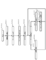
- FIG. 3 is a flowchart showing the positioning process in the first embodiment.
- FIG. 4 is a diagram for explaining the relationship between the position candidate group and the line-shaped area in the first embodiment.
- FIG. 1 is a conceptual diagram of a positioning system in the first embodiment.
- the positioning system 100 has a reference station 110 and a terminal 120.
- the reference station 110 is a communication station whose coordinates on the earth are known.
- the terminal 120 is an electronic device that exists in a place where the coordinates on the earth are to be obtained.
- the terminal 120 performs positioning called interference positioning.
- Interferometric positioning is a method for positioning based on the wavelength of a positioning signal transmitted from the satellite 130.
- the reference station 110 communicates with the terminal 120.
- the content that the reference station 110 performs in communication with the terminal 120 includes transmission / reception of positioning data.
- the positioning data is one piece of information necessary for positioning the position of the terminal 120 by interference positioning.
- the positioning system 100 determines the coordinates of the terminal 120 on the earth by positioning the terminal 120 using the correction information.
- FIG. 2 is a block diagram of the terminal in the first embodiment.
- the reference station 110 includes a processor 201, a storage unit 202, an input unit 203, an output unit 204, a communication unit 205, a receiving device 206, and a bus 210.
- the processor 201 controls other elements of the reference station 110 via the bus 210.
- the processor 201 can be configured by using a general-purpose CPU (Central Processing Unit). Further, the processor 201 can execute a predetermined program.
- the terminal 120 operates when the processor 201 executes a predetermined program.
- the storage unit 202 acquires various information from other elements and holds the information temporarily or permanently.
- the storage unit 202 is a general term for so-called primary storage devices and secondary storage devices, and a plurality of storage units 202 may be physically arranged.
- a DRAM Direct Random Access Memory
- HDD Hard Disk Drive
- SSD Solid State Drive
- the input unit 203 receives information from the outside.
- the external information received by the input unit 203 includes information related to input from the operator of the reference station 110.
- the input unit 203 can be configured by using an input interface such as a keyboard.
- the output unit 204 presents information to the outside.
- Information presented by the output unit includes information related to positioning.
- the output unit 204 can be configured by using an existing output interface such as a display.
- the communication unit 205 communicates with an external device via a communication path.
- the equipment with which the communication unit 205 communicates includes the reference station 110.
- the communication unit 205 can be configured by using a communication interface that can communicate with an existing communication network such as a wireless communication network, a wireless LAN communication network, and a 3G communication network using ultra high frequency waves (30 MHz to 0.3 GHz).
- the receiving device 206 has a receiving antenna and a demodulator.
- the receiving device receives a positioning signal from a positioning satellite.
- a GPS satellite is used as an example of a positioning satellite.
- the GPS satellite transmits an L1 signal (1575.42 MHz), an L2 signal (1222.70 MHz), etc. as positioning signals.
- the receiver demodulates the positioning signal received by the receiving device.
- the configuration of the terminal 120 mentioned above is an example. A part of each component of the terminal 120 may be integrated and configured. A part of each component of the terminal 120 may be divided into a plurality of elements. Some of the components of the terminal 120 may be omitted. The terminal 120 can be configured by adding other elements.
- FIG. 3 is a flowchart showing the positioning process in the first embodiment.
- step S300 the processor 201 of the terminal 120 starts a positioning process.
- step S301 the processor 201 calculates approximate coordinates of the terminal 120.
- the approximate coordinates are calculated by the processor 201 based on the positioning signal received by the receiving device 206.
- the process of calculating approximate coordinates based on a positioning signal is generally known as code positioning.
- the processor 201 analyzes (1) a code (pattern of 0 and 1) indicated by the positioning signal and (2) the time when the satellite transmits the code, thereby calculating approximate coordinates.
- the approximate coordinates calculated by code positioning include errors due to the influence of the ionosphere.
- step S302 the processor 201 determines whether or not the terminal 120 is at the line determination point.
- the user of terminal 120 wants to know whether or not terminal 120 is on a predetermined line-shaped area (for example, a track, a main road, a pipeline, etc.).
- the line determination point is a point for determining whether or not the terminal 120 is on the predetermined line-shaped area.
- Various methods are conceivable for implementing a function for determining whether or not the terminal 120 is in a line area in the processor 201. As an example, there is a method in which the user of the terminal 120 explicitly notifies the processor 201 via the input unit 203 that the point where the current terminal exists is a line determination point.
- a geographic database is registered in the storage unit 202 in advance, and the processor 201 is present when the code positioning coordinates obtained in step S301 match a predetermined area in the geographic database.
- the processor 201 determines the line direction.
- the line direction refers to the major axis direction of a predetermined line area (for example, a track, a main road, a pipeline, etc.).
- a sensor such as a geomagnetic sensor
- a predetermined angle with respect to the direction (with respect to the traveling direction) Vertical, etc.) can be defined as the line direction.
- the direction in which the terminal 120 faces or the traveling direction in which the terminal 120 is facing is identified from the transition of the approximate coordinates obtained by the code positioning obtained in step S301, and a predetermined angle with respect to the direction (with respect to the traveling direction) Vertical, etc.) can be defined as the line direction.
- Steps S302 and S303 described above are one method for the processor 201 to define a line area on the map. That is, if the processor 201 can determine a line-shaped area on the map by another method, the method can be changed to step S302 and step S303. For example, by previously registering a geographic database in the storage unit 202 and defining a line area in advance in the geographic database, the processor 201 can define a line area on the map.
- step S304 the processor 201 starts RTK positioning calculation processing (RTK calculation processing).
- RTK calculation processing is calculation processing for executing the RTK method which is one of interference positioning.
- positioning of the terminal 120 is performed using the carrier phase integrated value of the positioning signal transmitted by the positioning satellite.
- the integrated carrier phase value is the sum of (1) the number of positioning signal waves from the satellite to a certain point and (2) the phase. If the carrier wave phase integrated value is obtained, since the frequency (and wavelength) of the positioning signal is known, the distance from the satellite to a certain point can be obtained. Since the number of waves of the positioning signal is unknown, it is called an integer bias.
- the double difference is a value obtained by calculating the difference (single difference) of the carrier phase integrated value of one receiver for two satellites between the two receivers (the reference station 110 and the terminal 120 in this embodiment). It is a difference.
- four satellites are used for positioning using the RTK method. Therefore, the double difference is calculated for the combination of the four satellites.
- the processor 201 performs this calculation using the positioning data of the reference station 110 and the positioning data of the terminal 120 obtained in advance via the communication unit 205.
- the positioning data includes pseudorange information and carrier phase information.
- the pseudorange information is information related to the pseudorange between the satellite and itself (meaning the reference station 110 and the terminal 120).
- the pseudorange information can be generated by analyzing a positioning signal by a processor (the processor of the reference station 110 or the processor 201 of the terminal 120).
- the processor (1) the difference between the code pattern carried by the positioning signal and the code pattern generated by itself (2) the satellite signal generation time included in the message (NAVDATA) included in the positioning signal and its own signal reception time
- NAVDATA satellite signal generation time included in the message
- the arrival time of the positioning signal can be obtained based on the above two.
- the processor can determine the distance from the satellite by multiplying the arrival time by the speed of light. This distance includes errors due to differences between the satellite clock and its own clock. Normally, pseudorange information is generated for four satellites in order to reduce this error.
- Carrier phase information is the phase of the positioning signal received by itself.
- the positioning signals (L1 signal, L2 signal, etc.) are predetermined sine waves.
- the carrier phase information can be generated by the processor analyzing the positioning signal received by the receiving device.
- the integer bias can be estimated by various methods.
- estimation of an integer bias is performed by executing a procedure of (1) estimation of a float (FLOAT) solution by the least square method and (2) verification of a fixed (FIX) solution based on the float solution.
- FLOAT float
- FIX fixed
- the estimation of the float solution by the least square method is executed by creating a simultaneous equation using a combination of double differences generated for each time unit and solving the created simultaneous equation by the least square method. Simultaneous equations are generated for each unit of time called an epoch.
- the positioning data of the reference station 110 obtained in advance, the positioning data of the terminal 120 and the known coordinates of the reference station 110 are used.
- a group of terminal coordinate candidates obtained in this way is called a float solution.
- the integer value bias estimated from each float solution obtained as described above is a real number, whereas the true value of the integer value bias is an integer. Therefore, it is necessary to round the estimated integer value bias to an integer value. However, there are several possible combinations for rounding off the estimated integer bias. Therefore, it is necessary to test which candidate is a correct integer value. Coordinates obtained based on a solution that is considered to be certain to some extent as an integer bias by the test is called a fixed solution. Note that the positioning data of the reference station 110 is also used in order to improve the narrowing down of integer value candidates.
- the processor 201 performs the arithmetic processing shown above as RTK arithmetic processing.
- step S305 the processor 201 determines whether or not a fixed solution has been calculated in the RTK calculation process.
- step S305 When the fixed solution is calculated (YES in step S305), the coordinates of the terminal 120 obtained by the fixed solution have centimeter accuracy. Therefore, in step S306, the processor 201 outputs the position of the terminal 120 via the output unit 204.
- Various methods for outputting the position can be applied. As an example, a map may be displayed on a display as the output unit 204, and the coordinates of the terminal 120 may be displayed on the map.
- the float solution as a candidate for the fixed solution obtained in the process of calculating the integer value bias may be calculated in a shorter time than the fixed solution.
- step S307 even if the fixed solution is not calculated (NO in step S305), it is determined whether or not the position candidate group obtained based on the float solution is within a predetermined line range (step S307).
- Step S307 will be described with reference to FIG.
- FIG. 4 is a diagram for explaining the relationship between the position candidate group and the line-shaped area in the first embodiment.
- FIG. 4 is a view of the satellite 131, the satellite 132, and the ground surface looking down from above.
- the positioning signal 401 and the positioning signal 402 represent the positioning signals transmitted from the first satellite 131 and the second satellite 132 in a pseudo manner.
- the positioning signal has a predetermined frequency (wavelength). Therefore, when the predetermined phase of the positioning signal is plotted, it appears that the phase spreads from the satellite in a ripple pattern. This ripple can also be seen as an integer bias when the phase component in the RTK calculation is removed.
- positioning signals 401 and 402 simulate the situation when the integer value bias is regarded as a ripple.
- the solution candidate group is a location where the positioning signal 401 and the positioning signal 402 overlap.
- the RTK calculation is a calculation that simultaneously solves the number (+ phase) of a plurality of satellites. A state where a fixed solution is not obtained in the RTK calculation indicates that the number of the waves is indefinite. That is, the solution candidates in the RTK calculation appear in a lattice pattern like the solution candidate group shown in FIG.
- the processor 201 calculates the float solution even if the fixed solution is not obtained as described above.
- the float solution is a combination of certain specific coordinates and the likelihood that the coordinates are true terminal coordinates.
- There are a plurality of specific coordinate candidates and when an integer value bias is estimated based on a float solution having a high likelihood among the candidates, a plurality of integer value bias candidates are obtained.
- the position candidate group shown in FIG. 4 is a position candidate obtained based on the float solution.
- the position candidate group is a group of positions (position candidate group) measured based on an integer bias group estimated from the float solution. is there.
- step S307 the processor 201 determines whether or not the position candidate group is included in the linear area determined in step S303 or the like.
- the positioning method and the terminal of the present disclosure cause the processor to determine the position of the terminal by interference positioning using a plurality of positioning signals received from a plurality of satellites.
- the processor calculates an integer value bias for the plurality of positioning signals, selects a group of position candidates based on a float solution obtained by the calculation of the integer value bias, and the group of position candidates is a line shape It is notified that the terminal is located at a predetermined point on the map on the condition that it is included in the area.
- the processor calculates approximate coordinates of the position of the terminal and defines the line-shaped area based on the calculated approximate coordinates.
- the processor calculates a moving direction of the terminal, and defines the linear area based on the calculated moving direction.
- the processor defines the line-shaped area based on information obtained from a geographic database.
- the first embodiment has been described as an example of the technique disclosed in the present application.
- the technology in the present disclosure is not limited to this, and can also be applied to an embodiment in which changes, replacements, additions, omissions, and the like are appropriately performed.
- This disclosure can be applied to positioning, etc. that is performed when road construction, track construction, etc. are performed.
- positioning system 110 reference station 120 terminal 130 satellite 131 satellite 132 satellite 201 processor 202 storage unit 203 input unit 204 output unit 205 communication unit 206 receiver 210 bus 401 positioning signal 402 positioning signal
Landscapes
- Engineering & Computer Science (AREA)
- Radar, Positioning & Navigation (AREA)
- Remote Sensing (AREA)
- Computer Networks & Wireless Communication (AREA)
- Physics & Mathematics (AREA)
- General Physics & Mathematics (AREA)
- Position Fixing By Use Of Radio Waves (AREA)
Abstract
Description
以下、図1~4を用いて、実施の形態1を説明する。 (Embodiment 1)
The first embodiment will be described below with reference to FIGS.
図1は、実施の形態1における測位システムの概念図である。 [1-1. Constitution]
FIG. 1 is a conceptual diagram of a positioning system in the first embodiment.
以上のように構成した端末が行う測位処理を説明する。 [1-2. Operation]
A positioning process performed by the terminal configured as described above will be described.
以上のように本実施の形態において、本開示の測位方法、端末は、複数の衛星から受信する複数の測位信号を用いた干渉測位によって、プロセッサが端末の位置を測位する。前記プロセッサは、前記複数の測位信号に対する整数値バイアスの計算を行い、前記整数値バイアスの計算によって得られる、フロート解に基づいて位置候補の群を選択し、前記位置候補の群がライン状のエリア内に含まれることを条件として、前記端末が地図上の所定の地点に位置することを通知する。 [1-3. Effect]
As described above, in the present embodiment, the positioning method and the terminal of the present disclosure cause the processor to determine the position of the terminal by interference positioning using a plurality of positioning signals received from a plurality of satellites. The processor calculates an integer value bias for the plurality of positioning signals, selects a group of position candidates based on a float solution obtained by the calculation of the integer value bias, and the group of position candidates is a line shape It is notified that the terminal is located at a predetermined point on the map on the condition that it is included in the area.
以上のように、本出願において開示する技術の例示として、実施の形態1を説明した。しかしながら、本開示における技術は、これに限定されず、適宜、変更、置き換え、付加、省略などを行った実施の形態にも適用可能である。また、上記実施の形態1で説明した各構成要素を組み合わせて、新たな実施の形態とすることも可能である。 (Other embodiments)
As described above, the first embodiment has been described as an example of the technique disclosed in the present application. However, the technology in the present disclosure is not limited to this, and can also be applied to an embodiment in which changes, replacements, additions, omissions, and the like are appropriately performed. Moreover, it is also possible to combine each component demonstrated in the said
110 基準局
120 端末
130 衛星
131 衛星
132 衛星
201 プロセッサ
202 記憶部
203 入力部
204 出力部
205 通信部
206 受信装置
210 バス
401 測位信号
402 測位信号 100
Claims (8)
- 複数の衛星から受信する複数の測位信号を用いた干渉測位によって、プロセッサが端末の位置を測位する測位方法であって、
前記プロセッサは、
前記複数の測位信号に対する整数値バイアスの計算を行い、
前記整数値バイアスの計算によって得られる、フロート解に基づいて位置候補の群を選択し、
前記位置候補の群がライン状のエリア内に含まれることを条件として、
前記端末が地図上の所定の地点に位置することを通知する、
測位方法。 A positioning method in which a processor measures the position of a terminal by interference positioning using a plurality of positioning signals received from a plurality of satellites,
The processor is
Performing an integer bias for the plurality of positioning signals;
Selecting a group of position candidates based on a float solution obtained by the calculation of the integer value bias;
On the condition that the group of position candidates is included in a line-shaped area,
Notifying that the terminal is located at a predetermined point on the map,
Positioning method. - 前記プロセッサは、
前記端末の位置の概算座標を算出し、
算出された前記概算座標に基づいて前記ライン状のエリアを定義する、
請求項1に記載の測位方法。 The processor is
Calculate approximate coordinates of the location of the terminal,
Defining the line area based on the calculated approximate coordinates;
The positioning method according to claim 1. - 前記プロセッサは、
前記端末の移動方向を算出し、
算出された前記移動方向に基づいて前記ライン状のエリアを定義する、
請求項1に記載の測位方法。 The processor is
Calculating the direction of movement of the terminal;
Defining the linear area based on the calculated direction of movement;
The positioning method according to claim 1. - 前記プロセッサは、
地理データベースから得られる情報により前記ライン状のエリアを定義する、
請求項1に記載の測位方法。 The processor is
Defining the line area by information obtained from a geographic database;
The positioning method according to claim 1. - プロセッサを有し、
複数の衛星から受信する複数の測位信号を用いた干渉測位によって、自身の位置を測位する端末であって、
前記プロセッサは、
前記複数の測位信号に対する整数値バイアスの計算を行い、
前記整数値バイアスの計算によって得られる、前記端末の位置に対する第1の位置候補の群から、真の前記端末の位置であることの尤度に基づいて第2の位置候補の群を選択し、
前記第2の位置候補の群がライン状のエリア内に含まれることを条件として、
前記端末が地図上の所定の地点に位置することを通知する、
端末。 Have a processor,
A terminal that measures its own position by interference positioning using a plurality of positioning signals received from a plurality of satellites,
The processor is
Performing an integer bias for the plurality of positioning signals;
Selecting a second group of position candidates based on the likelihood of being the true position of the terminal from a group of first position candidates for the position of the terminal obtained by calculating the integer value bias;
On condition that the group of the second position candidates is included in a line-shaped area,
Notifying that the terminal is located at a predetermined point on the map,
Terminal. - 前記プロセッサは、
前記端末の位置の概算座標を算出し、
算出された前記概算座標に基づいて前記ライン状のエリアを定義する、
請求項5に記載の端末。 The processor is
Calculate approximate coordinates of the location of the terminal,
Defining the line area based on the calculated approximate coordinates;
The terminal according to claim 5. - 前記プロセッサは、
前記端末の移動方向を算出し、
算出された前記移動方向に基づいて前記ライン状のエリアを定義する、
請求項5に記載の端末。 The processor is
Calculating the direction of movement of the terminal;
Defining the linear area based on the calculated direction of movement;
The terminal according to claim 5. - 前記プロセッサは、
地理データベースから得られる情報により前記ライン状のエリアを定義する、
請求項5に記載の端末。 The processor is
Defining the line area by information obtained from a geographic database;
The terminal according to claim 5.
Priority Applications (4)
| Application Number | Priority Date | Filing Date | Title |
|---|---|---|---|
| CN201680003891.3A CN107003414B (en) | 2015-05-13 | 2016-05-10 | Positioning method and terminal |
| EP16792374.7A EP3296768B1 (en) | 2015-05-13 | 2016-05-10 | Positioning method and terminal |
| US15/524,850 US10459088B2 (en) | 2015-05-13 | 2016-05-10 | Positioning method and terminal |
| JP2017517611A JP6751852B2 (en) | 2015-05-13 | 2016-05-10 | Positioning method and terminal |
Applications Claiming Priority (2)
| Application Number | Priority Date | Filing Date | Title |
|---|---|---|---|
| JP2015-097799 | 2015-05-13 | ||
| JP2015097799 | 2015-05-13 |
Publications (1)
| Publication Number | Publication Date |
|---|---|
| WO2016181645A1 true WO2016181645A1 (en) | 2016-11-17 |
Family
ID=57248183
Family Applications (1)
| Application Number | Title | Priority Date | Filing Date |
|---|---|---|---|
| PCT/JP2016/002273 WO2016181645A1 (en) | 2015-05-13 | 2016-05-10 | Positioning method and terminal |
Country Status (5)
| Country | Link |
|---|---|
| US (1) | US10459088B2 (en) |
| EP (1) | EP3296768B1 (en) |
| JP (1) | JP6751852B2 (en) |
| CN (1) | CN107003414B (en) |
| WO (1) | WO2016181645A1 (en) |
Cited By (1)
| Publication number | Priority date | Publication date | Assignee | Title |
|---|---|---|---|---|
| CN110662987A (en) * | 2017-06-29 | 2020-01-07 | 松下知识产权经营株式会社 | Positioning method and positioning terminal |
Citations (10)
| Publication number | Priority date | Publication date | Assignee | Title |
|---|---|---|---|---|
| JP2005189141A (en) * | 2003-12-26 | 2005-07-14 | Railway Technical Res Inst | Gps measuring method of moving body position and its system |
| JP2006224737A (en) * | 2005-02-15 | 2006-08-31 | Japan Radio Co Ltd | Working section protecting system for railroad, train-mounted device for the same, and portable device for worker |
| JP2007071844A (en) * | 2005-09-09 | 2007-03-22 | Mitsubishi Electric Corp | Integer solution verifier and relative positioning apparatus |
| JP2008002975A (en) * | 2006-06-23 | 2008-01-10 | Port & Airport Research Institute | Method and device for discriminating false recognition of gps positioning data |
| JP2008172453A (en) * | 2007-01-10 | 2008-07-24 | Toshiba Corp | Information processor |
| JP2009074930A (en) * | 2007-09-20 | 2009-04-09 | Sumitomo Electric Ind Ltd | Positioning device, positioning system, computer program, and positioning method |
| JP2009270927A (en) * | 2008-05-07 | 2009-11-19 | Toyota Motor Corp | Inter-moving object interference positioning apparatus and method for moving object |
| JP2013205012A (en) * | 2012-03-27 | 2013-10-07 | Hitachi Zosen Corp | Method of displacement detection in gps observation point |
| WO2014171999A2 (en) * | 2013-02-04 | 2014-10-23 | Vanderbilt University | Method and system for high-accuracy differential tracking of global positioning system (gps) receivers |
| JP2015068768A (en) * | 2013-09-30 | 2015-04-13 | 日本電気株式会社 | Positioning system, device, method, and program |
Family Cites Families (5)
| Publication number | Priority date | Publication date | Assignee | Title |
|---|---|---|---|---|
| US8099108B2 (en) * | 2007-07-12 | 2012-01-17 | Sony Ericsson Mobile Communications Ab | Mobile terminals including display screens capable of displaying maps and map display methods for mobile terminals |
| US8792916B2 (en) * | 2008-01-14 | 2014-07-29 | Blackberry Limited | Dynamic prioritization of label downloads |
| DE112009002044B4 (en) * | 2008-08-19 | 2022-07-14 | Trimble Navigation Ltd. | Methods and apparatus for processing GNSS signals with ambiguity convergence indication |
| CN102171583B (en) * | 2008-10-06 | 2015-02-18 | 天宝导航有限公司 | Position estimation method and apparatus |
| CN101833080A (en) * | 2009-03-12 | 2010-09-15 | 周迅 | Method for measuring attitude of carrier by using additional constraint condition of GPS system |
-
2016
- 2016-05-10 EP EP16792374.7A patent/EP3296768B1/en active Active
- 2016-05-10 CN CN201680003891.3A patent/CN107003414B/en active Active
- 2016-05-10 WO PCT/JP2016/002273 patent/WO2016181645A1/en active Application Filing
- 2016-05-10 JP JP2017517611A patent/JP6751852B2/en active Active
- 2016-05-10 US US15/524,850 patent/US10459088B2/en active Active
Patent Citations (10)
| Publication number | Priority date | Publication date | Assignee | Title |
|---|---|---|---|---|
| JP2005189141A (en) * | 2003-12-26 | 2005-07-14 | Railway Technical Res Inst | Gps measuring method of moving body position and its system |
| JP2006224737A (en) * | 2005-02-15 | 2006-08-31 | Japan Radio Co Ltd | Working section protecting system for railroad, train-mounted device for the same, and portable device for worker |
| JP2007071844A (en) * | 2005-09-09 | 2007-03-22 | Mitsubishi Electric Corp | Integer solution verifier and relative positioning apparatus |
| JP2008002975A (en) * | 2006-06-23 | 2008-01-10 | Port & Airport Research Institute | Method and device for discriminating false recognition of gps positioning data |
| JP2008172453A (en) * | 2007-01-10 | 2008-07-24 | Toshiba Corp | Information processor |
| JP2009074930A (en) * | 2007-09-20 | 2009-04-09 | Sumitomo Electric Ind Ltd | Positioning device, positioning system, computer program, and positioning method |
| JP2009270927A (en) * | 2008-05-07 | 2009-11-19 | Toyota Motor Corp | Inter-moving object interference positioning apparatus and method for moving object |
| JP2013205012A (en) * | 2012-03-27 | 2013-10-07 | Hitachi Zosen Corp | Method of displacement detection in gps observation point |
| WO2014171999A2 (en) * | 2013-02-04 | 2014-10-23 | Vanderbilt University | Method and system for high-accuracy differential tracking of global positioning system (gps) receivers |
| JP2015068768A (en) * | 2013-09-30 | 2015-04-13 | 日本電気株式会社 | Positioning system, device, method, and program |
Non-Patent Citations (1)
| Title |
|---|
| See also references of EP3296768A4 * |
Cited By (1)
| Publication number | Priority date | Publication date | Assignee | Title |
|---|---|---|---|---|
| CN110662987A (en) * | 2017-06-29 | 2020-01-07 | 松下知识产权经营株式会社 | Positioning method and positioning terminal |
Also Published As
| Publication number | Publication date |
|---|---|
| US10459088B2 (en) | 2019-10-29 |
| EP3296768A4 (en) | 2018-05-23 |
| EP3296768B1 (en) | 2023-07-05 |
| JPWO2016181645A1 (en) | 2018-03-08 |
| US20180052238A1 (en) | 2018-02-22 |
| CN107003414A (en) | 2017-08-01 |
| EP3296768A1 (en) | 2018-03-21 |
| JP6751852B2 (en) | 2020-09-09 |
| CN107003414B (en) | 2021-04-13 |
Similar Documents
| Publication | Publication Date | Title |
|---|---|---|
| KR101154079B1 (en) | Method for determining initial location of navigation apparatus | |
| US7411545B2 (en) | Carrier phase interger ambiguity resolution with multiple reference receivers | |
| US10996342B2 (en) | Positioning apparatus and positioning method | |
| JP6593879B2 (en) | Satellite positioning system, positioning terminal, positioning method, and program | |
| US20210011171A1 (en) | Moving body positioning system, method, and program | |
| US11187812B2 (en) | Positioning method and positioning terminal | |
| US9720071B2 (en) | Mitigating effects of multipath during position computation | |
| CN107003412B (en) | Positioning method, positioning system, correction information generation method, correction information generation device, relay station in positioning system, and terminal | |
| JP7334503B2 (en) | POSITIONING METHOD, POSITIONING SYSTEM AND MOBILE STATION | |
| US20140180580A1 (en) | Module, device and method for positioning | |
| CN112313542A (en) | Positioning method and positioning terminal | |
| JP2016020812A (en) | Positioning correction information supplying device and satellite positioning device | |
| JP2011163817A (en) | Positioning apparatus and program | |
| KR101221931B1 (en) | Method and device for creating satellite measurement of ship using inertial sensor in weak signal environment | |
| JP2006090912A (en) | Positioning device, information distributing device, positioning method, and information distributing method | |
| WO2016181645A1 (en) | Positioning method and terminal | |
| US11047992B2 (en) | Positioning method and positioning terminal | |
| JP2010145178A (en) | Moving body position specification device | |
| JP2016188792A (en) | Position measuring method and position measuring system | |
| US10816675B2 (en) | Coordinate output method and coordinate output device | |
| KR20180057002A (en) | A location of a radio wave disturbance source and the transmission power estimation apparatus | |
| US11294072B2 (en) | Method, device and server for estimation of IFB calibration value | |
| KR102584796B1 (en) | Method and apparatus for location estimating using gis information | |
| WO2020004538A1 (en) | Structure monitoring server and structure monitoring system | |
| CN112352167B (en) | Positioning device, positioning method and positioning system |
Legal Events
| Date | Code | Title | Description |
|---|---|---|---|
| 121 | Ep: the epo has been informed by wipo that ep was designated in this application |
Ref document number: 16792374 Country of ref document: EP Kind code of ref document: A1 |
|
| REEP | Request for entry into the european phase |
Ref document number: 2016792374 Country of ref document: EP |
|
| WWE | Wipo information: entry into national phase |
Ref document number: 2016792374 Country of ref document: EP |
|
| ENP | Entry into the national phase |
Ref document number: 2017517611 Country of ref document: JP Kind code of ref document: A |
|
| WWE | Wipo information: entry into national phase |
Ref document number: 15524850 Country of ref document: US |
|
| NENP | Non-entry into the national phase |
Ref country code: DE |