WO2016171229A1 - Method for producing press-molded product, press-molded product, and pressing device - Google Patents
Method for producing press-molded product, press-molded product, and pressing device Download PDFInfo
- Publication number
- WO2016171229A1 WO2016171229A1 PCT/JP2016/062682 JP2016062682W WO2016171229A1 WO 2016171229 A1 WO2016171229 A1 WO 2016171229A1 JP 2016062682 W JP2016062682 W JP 2016062682W WO 2016171229 A1 WO2016171229 A1 WO 2016171229A1
- Authority
- WO
- WIPO (PCT)
- Prior art keywords
- top plate
- molded product
- curved
- press
- stepped portion
- Prior art date
Links
Images


Classifications
-
- B—PERFORMING OPERATIONS; TRANSPORTING
- B21—MECHANICAL METAL-WORKING WITHOUT ESSENTIALLY REMOVING MATERIAL; PUNCHING METAL
- B21D—WORKING OR PROCESSING OF SHEET METAL OR METAL TUBES, RODS OR PROFILES WITHOUT ESSENTIALLY REMOVING MATERIAL; PUNCHING METAL
- B21D22/00—Shaping without cutting, by stamping, spinning, or deep-drawing
- B21D22/20—Deep-drawing
- B21D22/26—Deep-drawing for making peculiarly, e.g. irregularly, shaped articles
-
- B—PERFORMING OPERATIONS; TRANSPORTING
- B21—MECHANICAL METAL-WORKING WITHOUT ESSENTIALLY REMOVING MATERIAL; PUNCHING METAL
- B21D—WORKING OR PROCESSING OF SHEET METAL OR METAL TUBES, RODS OR PROFILES WITHOUT ESSENTIALLY REMOVING MATERIAL; PUNCHING METAL
- B21D5/00—Bending sheet metal along straight lines, e.g. to form simple curves
- B21D5/01—Bending sheet metal along straight lines, e.g. to form simple curves between rams and anvils or abutments
-
- B—PERFORMING OPERATIONS; TRANSPORTING
- B21—MECHANICAL METAL-WORKING WITHOUT ESSENTIALLY REMOVING MATERIAL; PUNCHING METAL
- B21D—WORKING OR PROCESSING OF SHEET METAL OR METAL TUBES, RODS OR PROFILES WITHOUT ESSENTIALLY REMOVING MATERIAL; PUNCHING METAL
- B21D53/00—Making other particular articles
- B21D53/88—Making other particular articles other parts for vehicles, e.g. cowlings, mudguards
Definitions
- the present disclosure relates to a method for manufacturing a press-formed product, a press-formed product, and a press apparatus.
- the body of an automobile is assembled by overlapping the edges of a number of molded panels and joining them by spot welding to form a box, and joining structural members to the essential parts of the box by spot welding.
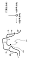
- a side sill joined to both side parts of a floor panel, an A pillar lower and an A pillar upper erected upward on the front part of the side sill, A roof rail joined to the upper end portion of the A pillar upper, and a B pillar that joins the side sill and the roof rail are used.
- Components of structural members such as an A pillar lower, an A pillar upper, and a roof rail (for example, each outer panel) generally have a top plate that extends in the longitudinal direction, and two components that are respectively connected to both sides of the top plate.
- Consists of a convex ridge line part, two vertical walls respectively connected to these two convex ridge line parts, two concave ridge line parts respectively connected to these two vertical wall parts, and two flanges respectively connected to these two concave ridge line parts Often has a substantially hat-shaped cross-sectional shape.
- the above-described components have a relatively complicated cross-sectional shape and are long. Therefore, in order to suppress an increase in manufacturing cost, the above-described components are generally manufactured by cold press molding. Further, in order to achieve both weight reduction and strength improvement of the vehicle body for improving fuel efficiency, thinning using, for example, a high-tensile steel plate having a tensile strength of 440 MPa or more is promoted as the above-described structural member.
- a high-strength steel plate blank is bent in the longitudinal direction by cold press forming, for example, a roof rail outer panel (hereinafter referred to as a roof member.
- the roof member is a structural member of an automobile). If it is going to manufacture the component which is, the springback will generate
- Patent Document 1 Japanese Patent Application Publication No. 2004-314123 (hereinafter referred to as Patent Document 1) gives a step when manufacturing a press-formed product having a uniform hat-shaped cross section in the longitudinal direction.
- Patent Document 1 Japanese Patent Application Publication No. 2004-314123
- Patent Document 2 Japanese Patent No. 5382281 (hereinafter referred to as Patent Document 2) includes a top plate, a vertical wall, and a flange, and the first step when manufacturing a press-formed product that curves in the longitudinal direction.
- the invention which raises the shape freezing property by bending back the flange formed in step 2 in the second step to reduce the residual stress of the flange is disclosed.
- Patent Document 1 when a press-molded product having a shape curved in the longitudinal direction, such as a component of a component of an A pillar lower, an A pillar upper, and a roof rail, is manufactured, a spring after release The curved wall is bent by the back and cannot be formed into a desired shape.
- Patent Document 2 when a press-molded product that is bent in the longitudinal direction and the height direction and has a bent portion in the vicinity of the center in the longitudinal direction is produced, the residual stress of the flange, the longitudinal wall, and the top plate Residual stress and deviation residual stress in the plane of the vertical wall and the top plate are generated. As a result, the press-molded product is bent from the top plate side due to the spring back after release, and cannot be molded into a desired shape.
- the specific press-molded product refers to a long top plate, ridge line portions at both ends in the short direction of the top plate, and facing each other in a state extending from the ridge line portion, and at least one of them.
- a press-formed product that includes a curved wall that is curved as viewed from above the top plate and a vertical wall that is curved.
- the method for manufacturing a press-formed product according to the first aspect of the present disclosure includes a long top plate, ridge lines at both ends of the top plate in a short direction, and facing each other in a state extending from the ridge line.
- a method of manufacturing a press-formed product comprising a vertical wall that is a curved wall that is curved when viewed from above the top plate, the top plate and ridge lines at both ends And an intermediate molded product in which a stepped portion is formed on the curved wall over the longitudinal direction of the top plate.
- the part on the opposite side of the part on the top plate side between the opposite side of the opposite side And a second step of performing at least one of be dynamic.
- the method for manufacturing a press-formed product according to the second aspect according to the present disclosure is the method for manufacturing the press-formed product according to the first aspect according to the present disclosure.
- the position of the top plate is determined.
- the protruding width is set to 20% or less of the width in the short direction of the top plate at a portion of the curved wall that is 40% or more of the height from the position of the top plate to the lower end of the curved wall. Forming a stepped portion.
- the method for manufacturing a press-formed product according to the third aspect of the present disclosure is the method for manufacturing the press-formed product according to the first or second aspect of the present disclosure, wherein at least the step portion in the second step.
- the angle of the stepped portion formed in the first step is changed by changing the angle of the portion of the curved wall that is closer to the top plate than the stepped portion.
- the protrusion width is narrowed.
- the press-formed product according to the present disclosure is a long top plate, a ridge line portion at both ends in the short direction of the top plate, and facing each other in a state extending from the ridge line portion, at least one of which is an upper side of the top plate A vertical wall that is curved as viewed from above, and a portion of the curved wall that is 40% or more of the height of the curved wall away from the position of the top plate in the curved wall.
- a stepped portion that protrudes with a protruding width of 20% or less of the width in the short direction of the top plate on the opposite side to the opposite side where the vertical walls face each other,
- the value of the Vickers hardness at the opposite end of the stepped portion is larger than the value of the Vickers hardness at the opposite end of the stepped portion.
- the press device includes a long top plate, ridge line portions at both ends in the short direction of the top plate, and facing each other in a state extending from the ridge line portion, at least one of which is opposed to each other.
- a vertical wall that is a curved wall that is curved when viewed from the upper side of the top plate, and the stepped portion that protrudes on the opposite side to the opposite side of the vertical wall is the longitudinal direction of the top plate
- a first press device that presses a blank to form the intermediate molded product formed on the curved wall, and a second press that presses the intermediate molded product to narrow the protruding width of the stepped portion. And a device.
- the press device includes the first press device that presses a blank with a first die and a first punch to form an intermediate molded product, and the second die and the second punch.
- a press device comprising a second press device for pressing an intermediate molded product, wherein the first die has a long first bottom surface and a first side surface connected to both ends of the first bottom surface in a short direction. And at least one of the first side surfaces is curved when viewed from the mold closing direction, and 40% of the depth of the first groove from the first bottom surface.
- the first punch has a shape that fits with the shape of the first groove when the mold is closed.
- a long second groove configured to include a long second bottom surface and second side surfaces connected to both ends in the short direction of the second bottom surface is formed in the second die and the second die.
- at least one of the second side surfaces is curved when viewed from the mold closing direction, and a second step portion is formed in the longitudinal direction of the second side surface at a position that is the specific depth from the second bottom surface.
- a second curved surface is formed, and the second stepped portion is narrower than the first stepped portion, and a separation distance from the second bottom surface along the short direction of the second bottom surface is the first curved surface. It is longer than the separation distance between the first bottom surface and the first step portion along the short side direction of the bottom surface, and the shape of the second punch is a shape that fits with the shape of the second groove when the mold is closed. And a second press device.
- a press device is the press device according to the second aspect of the present disclosure, wherein the second of the cross section of the second die projected onto the cross section of the first die. At least a part of the portion on the curved surface opposite to the portion on the second bottom surface side across the second step portion is on the second bottom surface side across the first step portion on the first curved surface. It is on the outside compared to the part opposite to the part.
- the press molded product according to the present disclosure has a small bend as viewed from the top plate side.
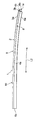
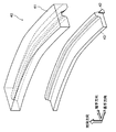
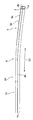
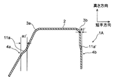
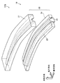
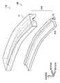
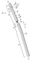
- FIG. 1A It is a top view which shows the roof member (press molded product) of 1st Embodiment. It is a side view which shows the roof member of 1st Embodiment. It is 1C-1C sectional drawing in FIG. 1A. 1D is a 1D-1D cross-sectional view in FIG. 1A.
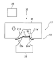
- FIG. It is a perspective view of the metal mold
- FIG. 1B is a cross-sectional view taken along the line 1C-1C of FIG. 1A in an intermediate molded product molded by the first step of the first embodiment.
- 1B is a cross-sectional view taken along the line 1D-1D of FIG. 1A in an intermediate molded product molded by the first step of the first embodiment.
- FIG. 1B is a cross-sectional view taken along the line 1C-1C of FIG.
- FIG. 1D is a 1D-1D cross-sectional view of the intermediate molded product molded by the second step of the first embodiment in FIG. 1A.
- 1B is a cross-sectional view showing in detail the 1C-1C cross-sectional view of FIG. 1A in the intermediate molded product formed by the first step of the first embodiment.
- FIG. 1B is a cross-sectional view showing in detail a 1D-1D cross-sectional view of FIG. 1A in an intermediate molded product formed by the first step of the first embodiment.
- FIG. 1B is a cross-sectional view showing in detail a 1C-1C cross-sectional view of FIG. 1A in a roof member manufactured through a second step of the first embodiment.
- FIG. 1B is a cross-sectional view showing in detail a 1D-1D cross-sectional view of FIG. 1A in a roof member manufactured through a second step of the first embodiment.
- FIG. It is sectional drawing of the longitudinal direction center part in the intermediate molded product shape
- FIG. 2 is a cross-sectional view of a portion corresponding to the 1C-1C cross-sectional view of FIG. 1A in the intermediate molded product formed by the first step of the first embodiment. It is sectional drawing of the longitudinal direction center part in the roof member manufactured through the 2nd process of 1st Embodiment.
- 1B is a cross-sectional view taken along the line 1C-1C of FIG.
- FIG. 1C is a cross-sectional view taken along the line 1C-1C of FIG. 1A in the intermediate molded product formed by the first step of the first embodiment, and is a cross-sectional view showing in detail an angle formed by a vertical wall and a flange.
- 1D is a 1D-1D cross-sectional view of FIG. 1A in an intermediate molded product formed by a first step of the first embodiment, and is a cross-sectional view showing in detail an angle formed by a vertical wall and a flange.
- FIG. 1C is a cross-sectional view taken along the line 1C-1C of FIG.
- FIG. 1A in a roof member manufactured through a second step of the first embodiment, and is a cross-sectional view showing in detail an angle formed by a vertical wall and a flange.
- 1D is a 1D-1D cross-sectional view of FIG. 1A in a roof member manufactured through a second step of the first embodiment, and is a cross-sectional view showing in detail an angle formed by a vertical wall and a flange.
- FIG. It is a top view which shows the roof member of 2nd Embodiment. It is a side view which shows the roof member of 2nd Embodiment.
- FIG. 8C is an 8C-8C cross-sectional view of FIG. 8A. It is 8D-8D sectional drawing of FIG. 8A.
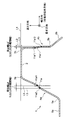
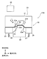
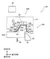
- FIG. 1 is a longitudinal cross-sectional view of the 1st press apparatus used at the 1st process in the manufacturing method of the roof member of 2nd Embodiment. It is a longitudinal cross-sectional view of the 2nd press apparatus used at the 2nd process in the manufacturing method of the roof member of 2nd Embodiment. It is a figure explaining the definition of the protrusion width
- 2 is a schematic view of a state in which a part of a longitudinal sectional view of a central portion in the longitudinal direction of an intermediate molded product 30 of the first embodiment and a part of a longitudinal sectional view of a central portion in the longitudinal direction of a roof member 1 are overlapped.
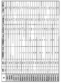
- FIG. 10 is a table showing the evaluation results by simulation of the bending of the roof member of the example of the second embodiment (Examples 10A to 16A) and the bending of the roof member of the comparative example (Comparative Examples 6A to 10A). It is a graph which shows the evaluation result by experiment about the Vickers hardness of the vertical wall of the comparative example 1A. It is a graph which shows the evaluation result by the experiment about the Vickers hardness of the vertical wall of Example 4A. It is a figure of the roof member of 3rd Embodiment, Comprising: It is the perspective view shown including the cross-sectional view in a longitudinal direction. FIG.
- FIG. 20 is a cross-sectional view of a roof member according to a third embodiment, and is a cross-sectional view taken along line 2-2 in FIG. It is a figure of the intermediate molded product of 3rd Embodiment, Comprising: It is the perspective view shown including the cross-sectional view in a longitudinal direction.
- FIG. 22 is a cross-sectional view of the intermediate molded product of the third embodiment, and is a cross-sectional view taken along line 4-4 in FIG.
- FIG. 23 is a schematic diagram in which a part of the cross-sectional view of FIG. 20 (two-dot chain line) is superimposed on a part of the cross-sectional view of FIG. 22 (solid line).
- First Embodiment The first embodiment will be described below. First, the structure of the roof member 1 of this embodiment shown in FIGS. 1A, 1B, 1C, and 1D will be described. Next, the configuration of the press device 17 of the present embodiment shown in FIGS. 2A, 2B, 3A, and 3B will be described. Next, a method for manufacturing the roof member 1 of the present embodiment will be described. Next, the operation of this embodiment will be described.
- roof member 1 is an example of a press-formed product and a specific press-formed product.
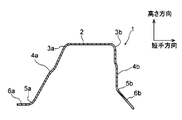
- the roof member 1 includes a top plate 2, two convex ridge lines 3a and 3b, two vertical walls 4a and 4b, and two concave ridge lines.
- the section 5a, 5b and the two flanges 6a, 6b are integrally formed to be a long member having a substantially hat-shaped cross section.
- the convex ridge line portions 3a and 3b are examples of the ridge line portion.
- the roof member 1 is a cold press-formed product made of a high-tensile steel plate having a tensile strength of 1310 MPa. That is, the roof member 1 of the present embodiment is a cold press-formed product made of a high-tensile steel plate having a tensile strength of 440 MPa to 1600 MPa, for example.
- the top plate 2 is long as shown in FIGS. 1A and 1. Further, as shown in FIG. 1A, the top plate 2 is curved along the longitudinal direction when viewed from the upper side of the top plate 2.
- the two convex ridge line portions 3 a and 3 b are formed at both ends of the top plate 2 in the short direction.
- the two vertical walls 4a and 4b are opposed to each other in a state of extending from the convex ridge line portions 3a and 3b, respectively. That is, the roof member 1 of the present embodiment is opposed to each other in a state where the long top plate 2, the convex ridge line portions 3 a and 3 b at both ends in the short direction of the top plate 2, and the convex ridge line portions 3 a and 3 b are extended.
- the vertical walls 4a and 4b are configured to be included. Further, as shown in FIG. 1A, the two vertical walls 4 a and 4 b are curved along the longitudinal direction of the top plate 2 when viewed from the upper side of the top plate 2. In other words, the two vertical walls 4a and 4b of the present embodiment are curved walls facing each other in a state of extending from the convex ridge line portions 3a and 3b, respectively, and at least one of which is curved as viewed from above the top plate 2. ing.
- the vertical walls 4a and 4b are examples of curved walls.
- the vertical wall 4a is curved in a concave shape toward the vertical wall 4b side, that is, the opposite side to the side facing the vertical wall 4b side
- the vertical wall 4b is the vertical wall 4a side
- it is curved in a convex shape toward the side opposite to the side facing the vertical wall 4a side.
- the two vertical walls 4 a and 4 b that is, both the vertical walls 4 a and 4 b are curved when viewed from the upper side of the top plate 2.
- each vertical section in the longitudinal direction of the top plate 2 of the present embodiment extends linearly in the lateral direction at each position in the longitudinal direction. That is, as shown in FIG. 1C and FIG. 1D, the top plate 2 of the present embodiment is flat at each position in the longitudinal direction when viewed in vertical sections in the longitudinal direction.
- the roof member 1 is curved in a convex shape toward the top plate 2 side in the longitudinal direction.
- the convex ridge line portion 3 a is a portion that connects the top plate 2 and the vertical wall 4 a, and is curved when each cross section perpendicular to the longitudinal direction of the top plate 2 is viewed. It is supposed to be a part.
- the convex ridge line portion 3a is not shown at both ends by the alternate long and short dash line, but is a portion that connects the top plate 2 and the vertical wall 4b, and is curved when each cross section perpendicular to the longitudinal direction of the top plate 2 is viewed. It is supposed to be a part.
- the two concave ridge line portions 5a and 5b are formed at the ends of the two vertical walls 4a and 4b opposite to the side connected to the top plate 2, respectively.
- the two flanges 6a and 6b are connected to the two concave ridge lines 5a and 5b, respectively.
- the concave ridge line portion 5a is not shown at both ends by the alternate long and short dash line, but is a portion that connects the vertical wall 4a and the flange 6a, and is curved when viewed in each cross section perpendicular to the longitudinal direction of the top plate 2. It is supposed to be a part.
- concave ridge line portion 5b is not shown at both ends by the alternate long and short dash line, but is a portion that connects the vertical wall 4b and the flange 6b, and is curved when viewed in a cross section perpendicular to the longitudinal direction of the top plate 2. It is said that it is a part.
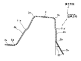
- the roof member 1 is viewed from the front end portion 1a, which is one end portion in the longitudinal direction, when viewed from the top plate 2 side in a state where the top plate 2 is disposed in an upper position. It curves over the rear end 1b which is the other end. From another viewpoint, as shown in FIGS. 1A and 1B, the roof member 1 includes a first portion 8 including one end 1a, and a third portion 10 including the other end 1b. It can be said that the second portion 9 that connects the first portion 8 and the third portion 10 is integrally formed.
- the curvature radius R of the first portion 8 when viewed from above, that is, when viewed from the upper side of the top plate 2, is set to 2000 (mm) or more and 9000 (mm) or less as an example.
- the radius of curvature R of the portion 9 is, for example, 500 (mm) or more and 2000 (mm) or less
- the radius of curvature R of the third portion 10 is, for example, 2500 (mm) or more and 9000 (mm) or less.
- the curvature radius R of the first portion 8 when viewed from the side, that is, when viewed from the width direction side of the top plate 2, is, for example, 3000 (mm) or more and 15000.
- the radius of curvature R of the second portion 9 is, for example, 1000 (mm) to 15000 (mm), and the radius of curvature R of the third portion 10 is, for example, 3000 (mm) to 15000 ( mm). As described above, the curvature radius R of the first portion 8 and the curvature radius R of the third portion 10 are larger than the curvature radius R of the second portion 9.
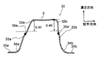
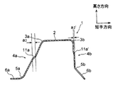
- the R-stop plate thickness center which is the R start point on the top plate 2 side of the convex ridge line portion 3 a, that is, the concave ridge line in the vertical wall 4 a from the plate thickness center of the top plate 2.
- the height to the lower end of the vertical wall 4a which is the end on the part 5a side is defined as a height h.
- a stepped portion 11a having a stepped amount a2 (mm) is formed on the vertical wall 4a from the thickness center of the top plate 2 over the longitudinal direction by 40% or more of the height h.
- the thickness center of the R-stop which is the R start point on the top plate 2 side of the convex ridge line portion 3b, that is, from the thickness center of the top plate 2 to the lower end of the vertical wall 4b.
- height be height h ′.
- a step portion 11a ′ having a step amount a2 ′ (mm) is formed in the longitudinal direction at a portion separated by 40% or more of the height h ′ from the thickness center of the top plate 2. ing.
- the thickness center of the top plate 2 is defined as a position in the height direction of the top plate 2.
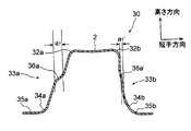
- the protrusion widths a2 and a2 ′ of the step portions 11a and 11a ′ are, as shown in FIG. 1D, the width W in the short direction of the top plate 2 at each position at each position in the longitudinal direction of the top plate 2. 20% or less.
- the side closer to the top plate 2, that is, the upper portion is the recess 11a1, and the far side from the top plate 2, that is, the lower portion is the projection 11a2.
- the side closer to the top plate 2, that is, the upper portion is the recess 11a'1, and the side far from the top plate 2, that is, the lower portion is the projection 11a'2.
- the value of the Vickers hardness of the convex portion 11a2 is 10 (HV) than the value of the Vickers hardness of the concave portion 11a1 at each position in the longitudinal direction of the vertical wall 4a, referring to FIG. ) Smaller than that.
- the value of Vickers hardness of convex part 11a'2 is 10 (HV) rather than the value of Vickers hardness of recessed part 11a'1 in each position in the longitudinal direction of the vertical wall 4b, if FIG. 18 mentioned later is referred. Smaller than that.
- step-difference part 11a, 11a it can paraphrase as follows. That is, the concave portion 11a1 that is the end closer to the top plate 2 of both ends of the stepped portion 11a is a portion that forms a radius of curvature that is the largest convex on the inner surface side of the inner surface of the vertical wall 4a.
- the convex portion 11a2 that is the end far from the top plate 2 is a portion that forms a radius of curvature that is the largest convex on the outer surface side of the inner surface of the vertical wall 4a.
- the concave portion 11a′1 which is the end closer to the top plate 2 among the both ends of the stepped portion 11a ′ is a portion that forms a radius of curvature that is the largest convex on the inner surface side of the inner surface of the vertical wall 4b.
- the convex portion 11 a ′ 2, which is the end far from the top plate 2 is a portion that forms a radius of curvature that is most convex on the outer surface side on the inner surface of the vertical wall 4 b.
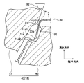
- FIG. 11 is a diagram illustrating the protruding width a2 of the stepped portions 11a and 11a '.
- the protruding width a2 of the stepped portion 11a is, for example, a virtual line L1 that connects both ends of the top plate 2 when a cross section perpendicular to the longitudinal direction of the roof member 1 is viewed. It means the separation width between the vertical line L2 passing through the convex part 11a2 and the vertical line L3 passing through the concave part 11a1.
- the virtual line L1 which connects the both ends of the top plate 2 shows the virtual line L1 which connects the convex ridgeline part 3a and the convex ridgeline part 3b, as FIG. 11 shows.
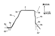
- the roof member 1 has different cross-sectional shapes of the flanges 6a and 6b at the front end 1a and the rear end 1b.
- the angle of the flange 6b with respect to the vertical wall 4b is 30 ° at the front end 1a and 40 ° at the rear end 1b.
- the angles of the flanges 6a and 6b with respect to the vertical wall 4a change continuously over the longitudinal direction.
- the width of the top plate 2 in the short direction changes so as to increase continuously, that is, increase from the front end 1a to the rear end 1b in the longitudinal direction.
- the angle formed between the vertical wall 4b of the first portion 8 and the flange 6b is equal to or greater than the angle formed between the vertical wall 4b of the third portion 10 and the flange 6b. It is preferable.
- the press apparatus 17 of this embodiment is for manufacturing the roof member 1 of this embodiment.
- the press device 17 includes a first press device 18 and a second press device 19 as shown in FIGS. 2A, 2B, 3A, and 3B.
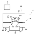
- the first press device 18 is used to press-mold the blank BL shown in FIG. 2B, for example, by drawing to form an intermediate molded product 30 shown in FIG. 3B, for example,
- the intermediate molded product 30 is press-molded by the second press device 19 to manufacture the product, that is, the roof member 1.
- the blank BL is a long high-tensile steel plate that is a base material for manufacturing the roof member 1.
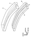
- the intermediate molded product 30 includes a top plate 2, two ridge line portions 32 a and 32 b, two vertical walls 33 a and 33 b, and two concave ridge line portions 34 a and 34 b, It is a substantially hat-shaped member that includes two flanges 35a and 35b.
- press molding means, for example, a molding object such as a blank BL and an intermediate molded product 30 such as a mold such as a first mold 20 and a second mold 40 described later. This refers to the act of setting the mold to closing the mold and opening the mold. That is, in this specification, “press forming” means pressing (pressurizing) a product to be formed and forming.
- the first press device 18 has a function of pressing the blank BL which is a molding target product and molding the intermediate molded product 30.
- the first press device 18 includes a first mold 20 and a first moving device 25.
- the first mold 20 has an upper mold 21, a lower mold 22, a first holder 23, and a second holder 24.
- the upper die 21 is an example of a first die.
- the lower die 22 is an example of a first punch.
- the upper mold 21 is disposed on the upper side, and the lower mold 22 is disposed on the lower side.
- the first press device 18 forms the blank BL into the intermediate molded product 30
- the upper plate 21 in the blank BL is sandwiched between the upper die 21 and the lower die 22 so that the top plate 2 in the blank BL is sandwiched between the upper die 21 and the lower die 22.
- the part to be molded is recessed from the upper mold 21 side to the lower mold 22 side.
- the upper mold 21 and the lower mold 22 are each long as shown in FIG. 2A.
- the upper mold 21 and the lower mold 22 are viewed from the facing direction of the upper mold 21 and the lower mold 22, as shown in FIGS. 2A and 2B, the lower mold 22 is curved and protrudes along the longitudinal direction.
- a groove that curves along the lower mold 22 is formed in the upper mold 21.
- the upper mold 21 and the lower mold 22 are viewed from the direction orthogonal to the opposing direction of the upper mold 21 and the lower mold 22, that is, from the short direction of the upper mold 21 and the lower mold 22, FIG. 2A and FIG.
- the lower mold 22 is curved in a convex shape toward the upper mold 21, and a groove that curves along the lower mold 22 is formed in the upper mold 21. Further, when viewed from the longitudinal direction, the bottom of the groove of the upper mold 21 protrudes toward the lower mold 22 with a radius of curvature R (mm) as shown in FIG. 2B, and the bottom of the groove of the upper mold 21 in the lower mold 22. The portion opposite to is recessed with a radius of curvature R (mm) on the upper mold 21 side.
- the curvature radius R (mm) of this embodiment is 100 (mm) as an example.
- the upper mold 21 when viewed from the short side of the upper mold 21, the upper mold 21 has a groove width that increases continuously from the bottom of the groove toward the opening side of the groove, that is, from the upper side to the lower side. Yes.
- the lower mold 22 When viewed from the short side of the lower mold 22, the lower mold 22 has a width of a first projecting portion, which will be described later, which is a projecting portion from the lower side toward the upper side.
- step portions 22a are respectively formed as shown in FIG. 2B. Further, on both side surfaces of the groove of the upper mold 21, step portions 21a are formed along the step portions 22a.
- the first holder 23 and the second holder 24 are elongated along the upper mold 21 and the lower mold 22.
- the 1st holder 23 and the 2nd holder 24 are arrange
- the first moving device 25 moves the upper die 21 toward the lower die 22. That is, the first moving device moves the upper mold 21 relative to the lower mold 22.
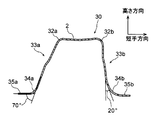
- FIG. 1 As shown in the drawing, the blank BL is pressed to form an intermediate molded product 30 with both ends in the short direction of the blank BL being sandwiched between the first holder 23, the second holder 24, and the upper die 21, respectively. It has come to be. Further, when the blank BL is pressed at the stepped portion 22a and the stepped portion 21a as the intermediate molded product 30 is formed, as shown in FIGS. 5A, 5B, 6A, and 6B, the vertical walls 33a and 33b are formed.
- Step portions 11a and 11a ′ having a projecting width a1 (mm) are formed at portions separated by 40% or more of the height of the vertical walls 33a and 33b from the position of the top plate 2 in FIG.
- step-difference part 11a, 11a ' is from the transversal direction of the top plate 2. As seen, the opposing sides are inclined more on the opening side than on the top plate 2 side.
- the stepped portions 11a and 11a ′ are inclined so that the facing distance between the stepped portions 11a and 11a ′ is larger on the opening side than the top plate 2 side, intermediate molding in which the stepped portions 11a and 11a ′ are formed. It can be said that the product 30 is formed by pressing.
- the upper mold 21 includes a long groove configured to include a first bottom surface that is a long bottom surface and first side surfaces that are side surfaces that are connected to both ends of the first bottom surface in the short direction.
- a first groove is formed.
- the first side surface is curved as viewed from the mold closing direction, that is, the facing direction of the upper mold 21 and the lower mold 22, and has a specific depth that is 40% or more away from the first bottom surface of the depth of the first groove.
- the step portions 11a and 11a ′ having a width of 20% or less of the width in the short side direction of the first bottom surface are formed as curved surfaces formed along the longitudinal direction of the first side surface. Yes.
- the lower mold 22 is adapted to fit in the first groove when the mold is closed.
- the step portions 11a and 11a ' are examples of the first step portion.
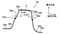
- the second press device 19 presses the intermediate molded product 30 that is the product to be molded, and narrows the protruding widths of the stepped portions 36a and 36a ′ having the protruding width a1 formed on the vertical walls 33a and 33b of the intermediate molded product 30. That is, it has a function of setting the protruding width of the stepped portions 36a and 36a ′ to a protruding width a2 that is narrower than the protruding width a1.
- the second press device 19 includes a second mold 40 and a second moving device 45.
- die 40 has the upper mold
- the upper die 41 is an example of a second die.
- the lower die 42 is an example of a second punch.
- the upper mold 41 is disposed on the upper side, and the lower mold 43 is disposed on the lower side.
- the lower mold 43 is urged from below by a spring 46.
- the second press device 19 moves the upper die 41 to the lower die 43 side by the second moving device in a state where the intermediate molded product 30 is fitted in the lower die 43, so that two flanges in the intermediate molded product 30 are provided.
- the angles of 35a and 35b are changed.
- stepped portions 43a are formed on both side surfaces of the lower mold 43, respectively. Further, on both side surfaces of the groove of the upper mold 41, step portions 41a are formed along the step portions 43a.
- the width of the stepped portion 43 a that is, the width in the short direction of the lower mold 43 is narrower than the width of the stepped portion 22 a of the first press device 18. Further, the width of the step portion 41 a, that is, the width in the short direction of the lower mold 43 is narrower than the width of the step portion 21 a of the first press device 18.
- the upper mold 41 When viewed from the short side of the upper mold 43, the upper mold 41 has a groove width that increases continuously from the bottom of the groove toward the opening side of the groove, that is, from the upper side to the lower side. Yes.
- the lower mold 43 When viewed from the short side of the lower mold 43, the lower mold 43 has a width of a second projecting portion, which will be described later, which is a projecting portion from the lower side to the upper side.
- the intermediate molded product 30 is pressed and the roof member 1 is molded. It has become.
- the vertical wall 33a is located on the upper side of the stepped portion 36a, that is, the top plate 2 side is on the side where the vertical walls 33a and 33b face each other, that is, on the side opposite to the facing side, While being bent outward, the protruding width of the stepped portion 36a having the protruding width a1 is set to a protruding width a2 that is narrower than the protruding width a1.
- the stepped portion 36a ′ of the vertical wall 33b is above the stepped portion 36a ′, that is, the top plate 2 side is the side where the vertical walls 33a and 33b face each other, that is, the side opposite to the facing side, That is, while being bent outward, the protruding width of the stepped portion 36a ′ having the protruding width a1 is set to a protruding width a2 that is narrower than the protruding width a1.
- type 43 are as above-mentioned, level
- the second press device 19 has been described.
- the second press device 19 is viewed as follows. That is, the upper die 41 includes a first bottom surface that is the bottom surface of the upper die 21 of the first press device 18, a second bottom surface that is the same shape as viewed from the mold closing direction, and a short bottom surface of the second bottom surface.
- a second groove that is a long groove including a second side surface that is a side surface connected to both ends in the hand direction is formed.
- the second side surface is curved when viewed from the mold closing direction, that is, the facing direction of the upper mold 41 and the lower mold 43, and extends from the second bottom surface to the above-described specific depth in the longitudinal direction of the second side surface.
- the second stepped portion is wider than the first stepped portion of the upper die 21 of the first press device 18 (the width here means the width in the short side direction of the first bottom surface or the second bottom surface). .) Is narrow and the distance between the second bottom surface along the short direction of the second bottom surface is longer than the distance between the first bottom surface along the short direction of the first bottom surface and the first step portion. .
- the lower mold 43 is adapted to fit in the shape of the second groove which is a groove when the mold is closed. That is, the shape of the lower die 43 is a shape that fits in the second groove when the die is closed.
- the method for manufacturing the roof member 1 of the present embodiment is performed using the press device 17.
- the method for manufacturing the roof member 1 of the present embodiment includes a first step that is a step performed by the first press device 18 and a second step that is a step performed by the second press device 19. .
- the blank BL is disposed at a position where a gap between the upper mold 21 and the lower mold 22 is determined.
- the upper die 21 is moved to the lower die 22 side by the first moving device, and the blank BL is press-formed by drawing. That is, in the first step, the blank BL that is the object to be molded is pressed using the upper mold 21 and the lower mold 22. As a result, the intermediate molded product 30 is molded from the blank BL.
- the two vertical walls 33a and 33b of the intermediate molded product 30 are provided with a height h of 60 from the flanges 35a and 35b.
- Step portions 36a and 36a ′ having a protruding width a1 defined by the following formulas (1) and (2) are formed in a portion within a range of less than%.
- the protruding width a1 of the stepped portions 36a and 36a ′ formed in the first step is wider than the protruding width a2 of the roof member 1 that is a product, and the roof member 1
- the width of the top plate 2 is 20% or less of the width W in the short direction.
- a1 is the protruding width (mm) of the stepped portions 33a and 33b in the intermediate molded product
- symbol a2 is the protruding width (mm) of the stepped portions 11a and 11a ′ in the roof member 1
- symbol W is in the roof member 1.
- the width (mm) in the short direction of the top plate 2 is shown.
- the vertical wall 33a is set so that the angle DI1 formed by the vertical wall 33a of the intermediate molded product 3 and the flange 35a satisfies the following expression (3). And the flange 35a is formed.
- the symbol DI1 is an angle formed by the vertical wall 33a of the intermediate molded product 30 and the flange 35a
- the symbol DI2 is an angle formed by the vertical wall 4a of the roof member 1 and the flange 6a.
- the vertical wall 33b and the flange 35b of the intermediate molded product 30 are formed so as to satisfy the following expression (4).
- DOF1 is an angle formed by the vertical wall 33b including the front end 1a of the intermediate molded product 30 and the flange 35b
- DOR1 is an angle formed by the vertical wall 33b including the rear end 1b of the intermediate molded product 30 and the flange 35b. It is.
- the outer flange 35b of the intermediate molded product 30 is formed by flowing the material end of the blank BL and bending the blank BL.
- the intermediate molded product 30 is removed from the first mold 20, and the first step is completed.
- the cross section orthogonal to the longitudinal direction of the top plate 2 in the intermediate molded product 30 is closed as shown in FIGS. 4A and 4B. It is in a state of being deformed so as to approach flatter than the time, that is, a state in which the radius of curvature is increased.
- the blank BL is deformed upward until the mold is closed, and then the portion of the blank BL where the top plate 2 is formed becomes convex downward when the mold is closed.
- the intermediate molded product 30 is formed by deforming and then opening the mold.
- the top plate 2 and the convex ridgeline portions 3a and 3b of the intermediate molded product 30 of the present embodiment are subjected to a Bausinger effect by receiving a load from the upper side to the lower side after being plastically deformed upward. It is in the state.
- the intermediate molded product 30 is fitted into the lower mold 43 of the second mold 40 of the second press device 19. And when an operator operates the 2nd press apparatus 19, the upper mold
- the angles of the two flanges 35a and 35b of the intermediate molded product 30 are changed. Further, in the second step, as shown in FIGS. 6A, 6B, 6C and 6D, and FIG. 12, above the stepped portions 36a and 36a ′ in the vertical walls 33a and 33b of the intermediate molded product 30, that is, By changing the angle of the portion on the top plate 2 side, the protruding width of the stepped portions 36a and 36a ′ is set to a protruding width a2 that is narrower than the protruding width a1.
- this embodiment as shown in FIG.
- the portion above the step portion 36 a in the vertical wall 33 a of the intermediate molded product 30 formed in the first step is the convex ridge line portion 3 a or the convex ridge line portion.
- the upper mold 41 moves the concave portion 11a1 to the arrow A direction side without moving the convex portion 11a2 of the stepped portion 11a while the intermediate molded product 30 is restrained by the lower mold 43.
- the portion above the stepped portion 36b in the vertical wall 33b of the intermediate molded product 30 formed in the first step is in the direction of arrow A with the convex ridge line portion 3b or the convex ridge line portion 32b as an axis. Rotate to the other side.
- the concave portion 11a1 is moved in the direction opposite to the arrow A direction without moving the convex portion 11a2 of the stepped portion 11a 'of the intermediate molded product 30.
- the protruding widths of the stepped portions 11a and 11a 'of the intermediate molded product 30 are set to the protruding widths a2 and a2' that are narrower than the protruding widths a1 and a1 ', respectively. Accordingly, in the second step, the concave portion 11a1 in the vertical wall 33a of the intermediate molded product 30, that is, the portion above the stepped portion 36a is moved in the direction opposite to the direction facing the vertical wall 33b. In the second step, the concave portion 11a'1 in the vertical wall 33b of the intermediate molded product 30, that is, the portion above the stepped portion 36a 'is moved in the direction opposite to the direction facing the vertical wall 33a.
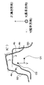
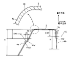
- FIG. 13 schematically shows a state before the intermediate mold 30 is fitted in the lower mold 43 and the second mold 40 is closed in the second step.
- the inclination angle is ⁇ 1
- the inclination angle ⁇ 2 of the part sandwiching the part is larger than the inclination angle ⁇ 1.
- the angular inclination angle of the upper mold 41 and the lower mold 43 sandwiching the upper portion of the stepped portion 36b of the vertical wall 33b is the portion of the vertical wall 33b above the stepped portion 36b.
- the protrusions of the stepped portions 36a and 36a ′ are changed by changing the angle of the upper portions of the vertical walls 33a and 33b of the intermediate molded product 30 from the stepped portions 36a and 36a ′.
- the protrusion width a2 is smaller than the protrusion width a1.
- the vertical wall 33a and the flange 35a in the intermediate molded product 30 become the vertical wall 4a and the flange 6a in the roof member 1.
- the intermediate molded product 30 is pressed.
- the vertical wall 33b and the flange 35b in the intermediate molded product 30 become the vertical wall 4b and the flange 6b in the roof member 1.
- the intermediate molded product 30 is pressed.
- a stepped portion 36a having a protruding width a1 is formed on the vertical wall 33a that is concavely curved toward the vertical wall 33b in the first step.
- the protruding width of the stepped portion 36a is changed from a1 to a2, which is narrower than a1.
- the vertical wall 33a and the stepped portion 33a become the vertical wall 4a and the stepped portion 11a, respectively.
- the roof member 1 of the present embodiment is a comparative form, and is a form in which a step portion is not formed. Comparative examples 1A to 4A of the table of FIG. Compared with the case of the above, it can be said that it is hard to bend or the amount of bend is small as viewed from the top 2 side. This reason is assumed to be due to the following mechanism. That is, in the case of this embodiment, the vertical wall 33a is plastically deformed by forming the step portion 36a in the vertical wall 33a in the first step. Next, in the second step, the protruding width of the stepped portion 36a is narrowed. For this reason, the step portion 11a of the roof member 1 is formed by receiving a load in the opposite direction to that in the first step, and thus it is presumed that the action of the Bauschinger effect is exerted.
- the stepped portion is not formed on the curved wall of the molded product including the curved wall that is concavely curved on the other wall side when viewed from the upper side of the top plate.
- the occurrence of bending of the roof member 1 is suppressed.
- the stepped portion is not formed on the curved wall of the molded product configured to include the curved wall that is concavely curved on the other wall side when viewed from the upper side of the top plate. Moreover, the tensile residual stress of the part above the level
- the protrusion width of the stepped portion 36a is narrowed by changing the angle of the portion of the vertical wall 33a closer to the top plate 2 than the stepped portion 36a. Therefore, according to this embodiment, even if it does not change the angle of the part on the opposite side to the top plate 2 side from the level
- a stepped portion 36a having a protruding width a1 is formed on the vertical wall 33b that is convexly curved toward the vertical wall 33a in the first step.
- the protruding width of the stepped portion 36a ′ is changed from a1 to a2 which is narrower than a1.
- the vertical wall 33b and the stepped portion 33b become the vertical wall 4b and the stepped portion 11a ', respectively.
- the roof member 1 of the present embodiment is a comparative form, and is a form in which a step portion is not formed.
- Comparative examples 1A to 4A of the table of FIG. It can be said that it is hard to bend or the amount of bend is small compared to the case of. This reason is assumed to be due to the following mechanism. That is, in the case of the present embodiment, the vertical wall 33b is plastically deformed by forming the step portion 36a 'in the vertical wall 33b in the first step.
- the angle of the portion of the vertical wall 33b closer to the top plate 2 than the stepped portion 36a ' is changed, and the protruding width of the stepped portion 36a' is narrowed. Therefore, since the step portion 11a 'of the roof member 1 is formed by receiving a load in the opposite direction to that in the first step, it is presumed that the effect of the Bauschinger effect is exerted.
- the stepped portion is not formed on the curved wall of the molded article configured to include the curved wall that is curved convexly on the other wall side when viewed from the upper side of the top plate.
- the occurrence of bending of the roof member 1 is suppressed.
- the residual stresses in the two vertical walls 4a and 4b are easily reduced, and the residual deviation stress between the two vertical walls 4a and 4b is reduced. easy. As a result, the occurrence of bending of the roof member 1 is suppressed.
- Second Embodiment a second embodiment will be described.
- the configuration of the roof member 1A of the present embodiment shown in FIGS. 8A, 8B, 8C, and 8D will be described.
- the configuration of the press device 17A of the present embodiment shown in FIGS. 9 and 10 will be described.
- a method for manufacturing the roof member of this embodiment will be described.
- the operation of this embodiment will be described. In the following description, only parts of the present embodiment that are different from the first embodiment will be described.
- the roof member 1A of the present embodiment is an example of a press-formed product and a specific press-formed product.
- the roof member 1A of the present embodiment includes the flanges 6a and 6b of the first embodiment shown in FIGS. 1A, 1B, 1C, and 1D. I do not have. Except for this point, the roof member 1A of the present embodiment has the same configuration as the roof member 1 of the first embodiment.
- the press device 17A of the present embodiment is for manufacturing the roof member 1A of the present embodiment.
- the first press device 18A of the present embodiment shown in FIG. 9 does not include the holders 23 and 24 shown in FIG. 2B.
- the first press device 18A is an example of a press device.
- the press device 17A of the present embodiment has the same configuration as the press device 17 of the first embodiment.
- the intermediate molded product 30A has the same configuration as the intermediate molded product 30 of the first embodiment, except that the two flanges 35a and 35b are not provided. That is, the intermediate molded product 30A of the present embodiment is a groove-shaped member.
- the manufacturing method of the roof member 1A of the present embodiment is performed using the press device 17A.
- the manufacturing method of the roof member 1A of the present embodiment is the same as that of the first embodiment except that the first step is performed by the first press device 18A.
- the blank BL is press-formed by bending to form an intermediate molded product 30A shown in FIG.
- First simulation> it was created by a simulation based on the roof member 1 shown in Examples 1A to 8A, which was created by a simulation based on the roof member production method of the first embodiment, and the roof member production described below.
- the roof members shown in Comparative Examples 1A to 5A the bending at the front end 1a side and the rear end 1b side was evaluated.
- the data SD for the roof members 1 of Examples 1A to 8A and the roof members of Comparative Examples 1A to 5A were compared with the design data DD using a computer (not shown). .
- a computer not shown.
- the cross section of the central portion in the longitudinal direction of the top plate 2 is made to coincide, that is, best fit, and measured with respect to the center position of the front end surface or the rear end surface in the design data DD.
- the shift amount in the width direction of the center position of the front end face or the rear end face of each data was evaluated as a bend.
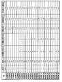
- the table in FIG. 15 describes simulation conditions and evaluation results for Examples 1A to 8A and Comparative Examples 1A to 5A.
- the plate thickness is the thickness of the blank BL used in the simulation.
- the strength is the tensile strength of the blank BL used for the simulation.
- the curved inner offset amount means a value obtained by subtracting the protrusion width a2 of the step portion 11a narrowed in the second step from the protrusion width a1 of the step portion 36a formed in the first step.
- the curved outer offset amount means a value obtained by subtracting the protrusion width a2 of the step portion 11a ′ narrowed in the second step from the protrusion width a1 of the step portion 36a ′ formed in the first step.
- the evaluation section 1 bend (mm) is a bend of 10 mm in the longitudinal direction from the front end 1 a to the center side
- the evaluation section 2 bend (mm) is a bend of 10 mm in the longitudinal direction from the rear end 1 b to the center.
- the average amount of bending is the average of the evaluation section 1 bend and the evaluation section 2 bend.
- roof members of Examples 1A to 8A were created by simulation on the premise of the manufacturing method of the roof member 1 of the first embodiment, that is, drawing.
- the protrusion width a1 of each stepped portion 36a, 36b was set to 5 (mm) in the first step.
- Example 1A The evaluation section 2 bend in Example 1A is ⁇ 1.12 (mm), but the meaning of “ ⁇ ” means that the bend is in the opposite direction to the case of the bend explanatory diagram of FIG. Therefore, when compared with the absolute value of the angle, it can be said that the roof member of Example 1A is less bent than the roof member of Comparative Example 1A. From the above, it is considered that Examples 1A to 5A, which are examples of the first embodiment, have the third effect compared to Comparative Examples 1A to 4A in which no step is formed on the vertical wall.
- Examples 1A and 2 in the second step, only one of the stepped portions 36a and 36b formed in the first step has the protruding width a1 narrowed. However, Examples 1A and 2 are less bent than Comparative Example 1A. From the above, Examples 1A and 2 which are examples of the first embodiment are smaller in bending than the comparative example (Comparative Example 1A) in which the step portion is not formed on the vertical wall. And it is thought that there exists a 2nd effect
- Example 7A it can be seen that the bending is smaller than that in Comparative Example 5A in which the simulation conditions for the plate thickness and strength are the same. From the above, Example 7A is considered to exhibit the first, second, and third actions as compared with Comparative Example 5A.
- Example 1A and Comparative Example 1A, Example 5A and Comparative Example 2A, etc. which are combinations in which the simulation conditions for plate thickness and strength are equivalent, are compared, Example 1A and Example 5A are respectively It can be seen that the average amount of bending is smaller than in Comparative Examples 1A and 2A. From the above, it is considered that Examples 1A to 8A exhibit the first, second, or third action regardless of the difference in tensile strength of the blank BL as compared with Comparative Examples 1A to 5A.
- Examples 9A to 16A which are the roof member 1 created by the simulation based on the roof member manufacturing method of the second embodiment, and the roof created by the simulation based on the roof member manufacturing described below.
- Examples 6A to 10A used as members the bending at the front end side and the rear end side was evaluated.
- roof members of Examples 9A to 16A were created by simulation on the premise of bending work, which is the manufacturing method of the roof member 1 of the first embodiment.
- the protrusion width a1 of each stepped portion 36a, 36b was set to 5 (mm) in the first step.
- Examples 9A and 10A in the second step, only one of the stepped portions 36a and 36b formed in the first step has the protruding width a1 narrowed. However, Examples 9A and 10A have less bending than Comparative Example 6A. From the above, Examples 9A and 10A, which are examples of the second embodiment, are less bent than Comparative Example 6A in which the stepped portion formed on the vertical wall in the first process is not narrowed in the second process. That is, it is considered that the first or second action is exhibited.
- Example 7A it can be seen that the bending is smaller than that in Comparative Example 5A in which the simulation conditions for the plate thickness and strength are the same. From the above, Example 7A is considered to exhibit the first, second, and third actions as compared with Comparative Example 5A.
- Example 9A and Comparative Example 6A, Example 13A and Comparative Example 7A, etc. which are combinations in which the simulation conditions for thickness and strength are equivalent, are compared
- Example 9A and 13A are comparative examples. It can be seen that the average amount of bending is small compared to 6A and 7A. From the above, it is considered that Examples 9A to 16A exhibit the first, second, or third action regardless of the difference in tensile strength of the blank BL as compared with Comparative Examples 6A to 10A.
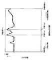
- ⁇ Third experiment> the value of the Vickers hardness of the vertical wall 4a of the roof member of Example 4A and the value of the Vickers hardness of the vertical wall 4a of the roof member of Comparative Example 1A were measured and compared.
- the value of Vickers hardness was measured according to the Vickers hardness measurement method described in JIS Z 2244 in the JIS standard.
- the Vickers hardness value is not limited to the Vickers hardness measurement method described in JIS Z 2244 in the JIS standard, but is measured by other methods and converted to the Vickers hardness value using a hardness conversion table (not shown). You may ask for it.
- JIS Z 2244 corresponds to ISO 6507-2: 2005 in the international standard.
- the convex portion It was found that the value of the Vickers hardness of 11a2 was smaller than the value of the Vickers hardness of the recess 11a1.
- the difference between the Vickers hardness value of the concave portion 11a1 and the Vickers hardness value of the convex portion 11a2 hereinafter, the Vickers hardness value of the concave portion 11a1 and the convex portion 11a2).
- Example 4A The difference from the value of the Vickers hardness of the difference ⁇ is 7) (HV). On the other hand, in the measurement result of Example 4A, the difference ⁇ was 10 (HV). Thus, the difference ⁇ in Example 4A is larger than the difference ⁇ in Comparative Example 1A. In other words, in the case of Example 4A, it can be said that the convex part 11a2 is softer than the concave part 11a1 than in the case of Comparative Example 1A. The reason is presumed as follows. That is, when the blank BL is press-molded in the first step, the step portion 36a is formed, and the convex portion 11a2 is pulled on the outer surface side, that is, tensile stress acts on the outside.
- the concave portion 11a1 moves to the convex portion 11a2 side.
- the convex portion 11a2 is in a state where the inner surface side is compressed more than the state at the time after the first step and before the second step.
- the recess 11a1 is pulled even after the first step and before the second step or after the second step. From the above, the convex portion 11a2 is softer than the concave portion 11a1.
- the concave portion 11a1 is harder than the convex portion 11a2, that is, the roof members 1 and 1A in the first embodiment and the second embodiment are more accurate than the comparative example 6A. That is, it can be said that bending is suppressed.
- omitted it was 8 (HV) when the difference (DELTA) of the comparative example 2A was measured, for example.
- difference (DELTA) of all the comparative examples other than the comparative example 1A and the comparative example 2A was measured all were less than 10 (HV).
- Example 5A and Example 7A when the difference ⁇ between Example 5A and Example 7A was measured, they were 30 (HV) and 20 (HV), respectively. Moreover, when difference (DELTA) of all Examples other than Example 5A and Example 7A was measured, all were 10 (HV) or more. That is, it was found that the difference ⁇ between the first and second embodiments and the roof members 1 and 1A of each example is 10 (HV) or more in any case.
- the roof members 1 and 1A of each example have better dimensional accuracy than the roof members of each comparative example.
- the roof members 1 and 1A of each example and other members (not shown)
- the correction amount that is, the deformation amount may be small. Therefore, in the case of each embodiment, there is an effect that the dimensional accuracy of the member joined to the other member is higher than in the case of each comparative example. Further, in the case of each example, compared to the case of each comparative example, since the stress does not remain or hardly remains in the welded portion of the joined member, there is an effect that the strength of the joined member is improved. .
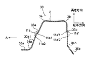
- roof member 1B is an example of a press-formed product and a specific press-formed product.
- the roof member 1B includes a top plate 2, two convex ridge line portions 3a and 3b, two vertical walls 4a and 4b, and two concave ridge line portions 5a and 5b.
- the cross-sectional shape which is comprised including the two flanges 6a and 6b integrally is a substantially hat-shaped long member.
- the convex ridge line portions 3a and 3b are examples of the ridge line portion.
- the roof member 1B is a cold press-formed product made of a high-tensile steel plate having a tensile strength of 1470 MPa.
- the configuration of the roof member 1B of the present embodiment shown in FIGS. 19 and 20 is the same as the configuration of the roof member 1 of the first embodiment shown in FIGS. 1A, 1B, 1C, and 1D. Yes.
- the press device 17B of this embodiment is for manufacturing the roof member 1B of this embodiment.
- the press device 17B includes a first press device 18 and a second press device 19B.
- the blank BL shown in FIG. 25 is pressed by drawing using the first press device 18 to form the intermediate molded product 30 shown in FIG. 21 and FIG.
- a product, that is, a roof member 1B is manufactured by press-molding the intermediate molded product 30 by the 2-press device 19B.
- the blank BL is a long high-tensile steel plate that is a base material for manufacturing the roof member 1B.
- the first press device 18 has a function of pressing the blank BL which is a molding target product and molding the intermediate molded product 30.
- the 1st press apparatus 18 is comprised including the 1st metal mold
- the first mold 20 includes an upper mold 21, a lower mold 22, a first holder 23, and a second holder 24.
- the upper die 21 is an example of a first die.
- the lower die 22 is an example of a first punch.
- the upper mold 21 is disposed on the upper side, and the lower mold 22 is disposed on the lower side.
- the upper mold 21 and the lower mold 22 are each long as shown in FIG.
- the lower mold 22 is curved and protrudes along the longitudinal direction.
- a groove that is curved is formed.
- the upper mold 21 has a groove width that increases continuously from the bottom of the groove toward the opening side of the groove, that is, from the upper side to the lower side. Yes.
- the width of the protruding portion of the lower mold 22 is continuously narrowed from the lower side to the upper side.
- type 22 is made into the shape fitted according to the shape of the groove
- stepped portions 22a are formed on both side surfaces of the lower mold 22, respectively. Further, on both side surfaces of the groove of the upper mold 21, step portions 21a and 21a 'are formed along the step portion 22a. In addition, the inclination angle with respect to the vertical direction of the portion below the stepped portion 21a on the side surface where the stepped portion 21a is formed, that is, the direction in which the upper mold 21 and the lower mold 22 face each other is ⁇ 1.
- the first holder 23 and the second holder 24 are elongated along the upper mold 21 and the lower mold 22.
- the 1st holder 23 and the 2nd holder 24 are arrange
- the first moving device 25 moves the upper die 21 toward the lower die 22. That is, the first moving device moves the upper mold 21 relative to the lower mold 22.
- the first moving device moves the upper mold 21 toward the lower mold 22 in a state where the blank BL is disposed at a position where the gap between the upper mold 21 and the lower mold 22 is defined, as shown in FIG.
- the blank BL is pressed to form the intermediate molded product 30 in a state where both ends in the short direction of the blank BL are sandwiched between the first holder 23, the second holder 24, and the upper die 21, respectively. It has become.
- FIG. 22 shows, with shaping
- a stepped portion 11a having a protruding width a1 (mm) is formed in a portion separated by 40% or more of the height.
- the blank BL is pressed at the stepped portion 22 a ′ and the stepped portion 21 a ′ along with the molding of the intermediate molded product 30, so that the vertical wall 33 b is vertically moved from the position of the top plate 2.
- a stepped portion 11a ′ having a protruding width a1 (mm) is formed in a portion separated by 40% or more of the height of the wall 33b.
- the stepped portions 21a and 21a ' are on the top plate 2 side when viewed from the longitudinal direction of the top plate 2. Further, the distance between the opposing surfaces becomes larger on the opening side, that is, they are inclined so as to widen the opposing width. From another viewpoint, the stepped portions 21a and 21a 'are inclined so that the facing distance between them is larger on the opening side than on the top plate 2 side.
- the upper mold 21 includes a first bottom surface that is a long bottom surface, and first side surfaces that are side surfaces facing each other in a state where each end is connected to both ends of the bottom surface in the short direction.
- a first groove that is a long groove is formed.
- the first side surface is curved when viewed from the mold closing direction, that is, the facing direction of the upper mold 21 and the lower mold 22, and the first side surface is located at a portion away from the first bottom surface by 40% or more of the depth of the first groove.
- Step portions 11a and 11a ′ having a width of 20% or less of the width in the short side direction of the bottom surface are first curved surfaces formed over the longitudinal direction of the first side surface.
- the lower mold 22 is adapted to fit in the first groove when the mold is closed. That is, the inclination angle with respect to the vertical direction of the lower portion of the lower mold 22 relative to the stepped portion 22a, that is, the opposing direction of the upper mold 21 and the lower mold 22, is ⁇ 1.
- the second press device 19 ⁇ / b> B presses the intermediate molded product 30 that is a product to be molded, and the step portion 11 a formed on the vertical wall 33 a of the intermediate molded product 30.
- the function of moving the portion 33a1 on the other end side, that is, the concave ridge line portion 34a side, to the side where the vertical walls 33a and 33b face each other, that is, the opposite side, that is, the arrow A direction side in the figure. Have.
- the 2nd press apparatus 19B is comprised including the 2nd metal mold
- the second mold 40 ⁇ / b> B includes an upper mold 41, a lower mold 43 ⁇ / b> B, and a holder 42.
- the upper mold 41 is disposed on the upper side
- the lower mold 43B is disposed on the lower side.
- the lower mold 43B is biased from below by a spring 46.
- the second press device 19B moves the upper die 41 to the lower die 43B side by the second moving device 45 in a state in which the intermediate molded product 30 is fitted in the lower die 43B, so that two The angles of the flanges 35a and 35b are changed.
- stepped portions 43a are formed on both side surfaces of the lower mold 43B. Further, stepped portions 41a along the stepped portions 43a are formed on the curved surfaces which are both side surfaces of the groove of the upper mold 41, respectively.
- the step portion 41a is an example of a second step portion.
- the shape of the stepped portion 43 a is equivalent to the shape of the stepped portion 22 a of the first press device 18.
- the step portion 43a is formed at a position corresponding to the step portion 22a, that is, a position where the step portions 11a and 11a 'of the intermediate molded product 30 overlap.
- the shape of the stepped portion 41 a is equivalent to the shape of the stepped portion 21 a of the first press device 18.
- the step portion 41a is formed at a position corresponding to the step portion 22a ', that is, a position where the step portions 11a and 11a' of the intermediate molded product 30 overlap.
- the upper die 41 has a groove width from the bottom of the groove toward the opening side of the groove, that is, from the upper side to the lower side, as viewed from the longitudinal direction of the upper die 41. Is continuously widened.
- the width of the protruding portion of the lower mold 43B is continuously narrowed from the lower side to the upper side.
- type 43B is made into the shape fitted according to the shape of the groove
- the second moving device 45 moves the upper mold 41 toward the lower mold 43B with the intermediate molded article 30 fitted in the lower mold 43B, the intermediate molded article 30 is pressed and the roof member 1B is molded. It is like that.
- the portion 33a1 on the other end side of the step portion 36a in the vertical wall 33a is moved to the side (opposite side) opposite to the side (opposite side) where the vertical walls 33a and 33b face each other. It is like that.
- the inclination angle ⁇ 2 with respect to the vertical direction of the lower portion of the lower mold 43B than the stepped portion 43a, that is, the facing direction of the upper mold 21 and the lower mold 22, is larger than the inclination angle ⁇ 1.
- the stepped portions 43a and 41a are on the top plate 2 side when viewed from the short side of the top plate 2. Further, the distance between the opposing surfaces becomes larger on the opening side, that is, they are inclined so as to widen the opposing width. From another viewpoint, the stepped portions 41a and 41a 'are inclined so that the facing distance between them is larger on the opening side than on the top plate 2 side.
- the second press device 19B has been described.
- another view of the second press device 19B is as follows. That is, the upper die 41 has a first bottom surface that is the bottom surface of the upper die 21 of the first press device 18, a second bottom surface that is a bottom surface having the same shape as viewed from the mold closing direction, and each end is second.
- An example of a second groove that is a long groove that is connected to both ends of the bottom surface in the short-side direction and includes a second side surface that is a side surface facing each other is formed.
- the second curved surface which is at least one of the second side surfaces, is curved when viewed from the mold closing direction, that is, the facing direction of the upper mold 41 and the lower mold 43B, and corresponds to the first step portion.
- the second curved surface has a second step portion formed at a position. Further, the angle ⁇ 2 at which the portion on the other end side with respect to the second step portion on the second curved surface is inclined with respect to the mold closing direction is such that the portion on the other end side with respect to the first step portion on the first curved surface is mold-closed. It is larger than the angle ⁇ 1 inclined with respect to the direction. Further, the lower die 43B is adapted to be fitted in accordance with the shape of the second groove when the die is closed. That is, the shape of the lower die 43B is a shape that fits in the second groove when the die is closed.
- the manufacturing method of the roof member 1B of this embodiment is demonstrated, referring drawings.
- the manufacturing method of the roof member 1B of this embodiment is performed using the press apparatus 17B.
- the manufacturing method of the roof member 1B of the present embodiment includes a first step that is a step performed by the first press device 18 and a second step that is a step performed by the second press device 19B. .
- the blank BL is disposed in the gap between the upper mold 21 and the lower mold 22.
- the upper die 21 is moved to the lower die 22 side by the first moving device, and the blank BL is press-formed by drawing. That is, in the first step, the blank BL that is the object to be molded is pressed using the upper mold 21 and the lower mold 22.
- the intermediate molded product 30 is molded from the blank BL. And the intermediate molded product 30 is removed from the 1st metal mold
- the intermediate molded product 30 is fitted into the lower mold 43B of the second mold 40B of the second press device 19B. And when an operator operates the 2nd press apparatus 19B, the upper mold
- the intermediate molded product 30 is pressed, and the side opposite to the side connected to the convex ridge line portions 3a and 3b rather than the step portions 11b and 11b ′ in the vertical walls 4a and 4b that are curved walls. Is moved to the opposite side to the opposite side where the vertical walls 4a and 4b face each other. And the roof member 1B is removed from the 2nd metal mold
- the blank member BL is pressed by the second press device 19B to form the roof member. Except for this point, the comparative form is the same as the present embodiment.
- the tip end bending is 4.38 (mm)
- the rear end bending is 5.85 (mm)
- the average bending amount is 5.12 ( mm).
- the data SD of the roof member created by the simulation based on the manufacturing method of the roof member of the comparative form with respect to the design data DD, and the manufacturing method of the roof member of the present embodiment The data SD of the roof member 1B created by the simulation based on the above was compared. Specifically, by using a computer (not shown), the front end portion or the rear end in the design data DD as shown in FIG.
- the amount of deviation in the width direction of the center position of the measured data SD with respect to the center position of the section in the width direction is a bend, and the average value of the value of the bend of the front end and the bend of the rear end is an average bend. The amount.
- Example 9B of the present embodiment As shown in the table of FIG. 32, the tip portion bending of the roof member 1B created by the simulation based on the manufacture of the roof member of the present embodiment is 5 0.02 (mm), rear end bending was 4.34 (mm), and average bending amount was 4.68 (mm). That is, in Example 9B, it can be said that the occurrence of bending of the top plate 2 in the short direction due to the spring back is suppressed as compared with Comparative Example 5B.
- the reason why the occurrence of bending as viewed from the top plate 2 side is suppressed as compared to the case of the comparative form is presumed as follows. That is, in the case of the comparative form, as described above, the blank BL is pressed by the second press device 19B to form the roof member.
- the vertical wall 4a of the roof member is a curved surface that curves in a convex shape on the side opposite to the side facing the vertical wall 4b. Further, the vertical wall 4 b is inclined with respect to the vertical direction, that is, the thickness direction of the top plate 2.
- the target shape is likely to be obtained after the outer surface of the portion 4a1 is bent due to the compressive stress.
- the bending stress is applied to the outer surface of the portion 4a1, it is easier to be molded within the allowable bending value.
- the top plate by the spring back is compared with the case where the vertical wall 33a of the intermediate molded product 30 is not moved to the side opposite to the side where the vertical walls 33a and 33b face each other. 2 is prevented from being bent in the short direction.
- the vertical wall 4a is compared with the case where the vertical wall 33a of the intermediate molded product 30 is not moved to the side opposite to the side where the vertical walls 33a and 33b face each other. It is possible to reduce the tensile residual stress in the portion below the step portion 11a and the compressive residual stress in the portion below the step portion 11a ′ in the vertical wall 4b.
- the configuration of the roof member 1C of the present embodiment will be described with reference to the drawings.
- the roof member 1C is an example of a press-formed product and a specific press-formed product.
- the roof member 1C of this embodiment does not include the flanges 6a and 6b shown in FIGS. 19 and 20 in the third embodiment, as shown in FIGS. Except for this point, the roof member 1C of the present embodiment has the same configuration as the roof member 1B of the third embodiment.
- a press apparatus (not shown) of the present embodiment is for manufacturing the roof member 1C.
- the first press device (not shown) of the present embodiment does not include the holders 23 and 24.
- the 1st press apparatus of this embodiment is set as the structure similar to the press apparatus 17B of 3rd Embodiment except this point.
- the intermediate molded product molded by the first press device has the same configuration as the intermediate molded product 30A of the second embodiment. That is, the intermediate molded product of this embodiment is a groove-shaped member as viewed from the longitudinal direction of the top plate 2.
- the manufacturing method of the roof member 1C of the present embodiment is the same as that of the third embodiment except that the first press device of the present embodiment is used instead of the first press device 18 of the third embodiment.
- the blank BL is press-molded by bending in the first step to form an intermediate molded product, and the intermediate molded product is press-formed by bending in the second step to form the roof member 1C. Molded.
- the roof member 1B of Examples 1B to 19B created by the simulation based on the method of manufacturing the roof member of the third embodiment and the manufacture of the roof member of the above-described comparative example are manufactured.
- the roof members of Comparative Examples 1B to 6B prepared by simulation based on the method the bending and average bending amount at the front end 1a and the rear end 1b were evaluated. Further, in this simulation, as shown in the table of FIG.
- the plate thickness is the thickness of the blank BL used in the simulation.
- the strength is the tensile strength of the blank BL used for the simulation.
- the outer vertical wall change start point (%) is the position in the height direction of the other end of the portion 33a1, that is, the end connected to the concave ridge line portion 34a with the convex portion 11a2 of the intermediate molded product 30 as a reference (0%). Indicates the start position of the portion 33a1 in the case where 100 is 100%. For example, FIG.
- FIG. 31 shows a case where the outer vertical wall change start point is 50%. Further, “ ⁇ ” as the outer vertical wall change start point (%) means that there is no change start point in the first place, that is, the portion 33a1 is not moved in the second step.
- the inner vertical wall change start point (%) is the other end of the portion 33b1 below the convex portion 11a'2 with respect to the convex portion 11a'2 of the intermediate molded product 30 (0%), that is, a concave ridge line.
- the start position of the part 33b1 when the position in the height direction of the end part connected to the part 34b is 100% is shown.
- FIG. 31 shows a case where the inner vertical wall change start point is 50%.
- the inner vertical wall change start point (%) being “ ⁇ ” means that there is no change start point in the first place, that is, the portion 33b1 is not moved in the second step. Therefore, in order to form the roof member 1B in FIG. 31, only the second press device is different from the second press device 19B of the press device 17 of the third embodiment. Specifically, in the second press device, at least a part of the second step portion of the second curved surface of the second die cross section projected on the cross section of the first die is at least part of the second die section. It is set as the structure which exists in the outer side compared with the part of the other end side rather than the said 1st level
- the second press device presses the intermediate molded product 30 that is the molding target product, and the other end side of the step portion 11a ′ formed on the vertical wall 33b of the intermediate molded product 30, that is, the concave ridge line portion 34b.
- the side portion 33b1 has a function of moving the vertical walls 33a and 33b to the side where the vertical walls 33a and 33b face each other, that is, the side opposite to the facing side.
- the roof members of Comparative Examples 1B to 4B are examples of the comparative form of the third embodiment described above.
- the roof members of Examples 1B to 19B are examples of the roof member 1B of the third embodiment.
- the roof member 1B of the example has a smaller bending amount or a bending amount than the comparative example when compared with the roof member of the comparative example under the same plate thickness and strength conditions.
- Example 1B is compared with Comparative Example 1B
- Example 3B is compared with Comparative Example 2B
- the bending of the example is smaller or the amount of bending is smaller than the comparative example in any case. That is, these examples are considered to have the effects of the third embodiment.
- Example 14B has a smaller bend or smaller bend than Comparative Example 5B.
- the portion 33b1 below the step portion 11a ′ of the vertical wall 4b is moved in the direction opposite to the direction facing the vertical walls 33a and 33b.
- the vertical wall 4b is a curved surface that is concavely curved on the side opposite to the side facing the vertical wall 4b when viewed from the top plate 2.
- the roof members of Example 5B and Example 9B are pulled on the outer surface of the moved portion 33b1 compared to Comparative Example 5B.
- the target shape is likely to be obtained after bending due to stress.
- the roof member of Example 14B compared to the case of Comparative Example 5B
- the outside of the moved portion 33b1 After the surface is bent due to the tensile stress, it is easy to be molded within the allowable value of bending.
- the roof members of Comparative Examples 7B to 12B are examples of comparative forms with respect to the third embodiment described above.
- the roof members of Examples 20B to 37B are examples of the roof member 1B of the third embodiment.
- the roof member of the example has a smaller bend or less bend amount than the comparative example in the case of the same thickness and strength as compared with the roof member of the comparative example.
- the bending of the example is smaller or the amount of bending is smaller than the comparative example in any case. That is, Example 20B and Example 21B are considered to have the effects of the fourth embodiment.
- Example 31B is less bent or less bent than Comparative Example 11B.
- the portion 33b1 below the step portion 11a ′ of the vertical wall 4b is moved in the direction opposite to the direction facing the vertical walls 33a and 33b.
- the vertical wall 4b is a curved surface that is concavely curved on the side opposite to the side facing the vertical wall 4b when viewed from the top plate 2.
- the target shape is likely to be formed after bending due to tensile stress acting on the outer surface of the moved portion 33b1 as compared with Comparative Example 11B.
- the outer surface of the moved portion 33b1 is easily bent and formed within the allowable bending value after bending.
- the press-molded product may be an automotive part other than the roof members 1 and 1A as long as the product is manufactured by press molding that satisfies the condition of the formula (1). Moreover, if it is a thing manufactured by press molding which satisfy
- the stepped portions 11a and 11a ' are formed on the vertical walls 4a and 4b which are curved walls, respectively.
- the level difference 36a, 36a ' is formed on one of the vertical walls 4a, 4b, the level difference 36a, 36a' may not be formed on the other vertical wall 4a, 4b.
- the vertical walls 4a and 4b are curved walls.
- any one of the vertical walls 4a and 4b is a curved wall, and stepped portions 11a and 11a ′ manufactured by the manufacturing method of the roof members 1 and 1A of the respective embodiments are formed on the curved wall on the stepped portion.
- the other vertical walls 4a and 4b may not be curved walls.
- the other vertical walls 4a and 4b may be straight walls along the longitudinal direction.
- the protruding width a1 of the step portion of the curved wall formed in the first step is narrowed in the second step to be a2 narrower than a1.
- the stepped portion formed in the first step may be eliminated in the second step. That is, in the present disclosure, “narrowing the protruding width of the stepped portion” includes eliminating the protruding width of the stepped portion, in other words, eliminating the stepped portion itself.
- the press-formed product is described as the roof members 1B and 1C.
- the intermediate molded product is manufactured by including the step of pressing the intermediate molded product and moving the portion on the other end side of the curved wall to the opposite side from the stepped portion, the press molded product is a roof member. Parts for automobiles other than 1B and 1C may be used.
- the product includes a step of pressing the intermediate molded product and moving the portion on the other end side with respect to the stepped portion of the curved wall to the opposite side, it is a component other than an automotive component. Also good.
- the vertical walls 4a and 4b are curved walls.
- any one of the vertical walls 4a and 4b is a curved wall, and the intermediate molded product is pressed to move the other end side portion of the curved wall to the opposite side from the stepped portion.
- the other vertical walls 4a and 4b may not be curved walls as long as they are molded.
- the other vertical walls 4a and 4b may be straight walls along the longitudinal direction.
- the intermediate molded product 30 is pressed by the second step after the first step to form the step portions 11a, 11a of the vertical walls 33a, 33b. It has been explained that the width of the protrusion width a1 of 'is reduced. However, in the first and second embodiments and the second step in the example, at least the intermediate molded product 30 is pressed to reduce the width of the protruding width a1 of the step portions 11a and 11a ′ of the vertical walls 33a and 33b. Other molding may be performed in the second step. For example, the second step in the third and fourth embodiments and the example may be performed in the second step in the first and second embodiments and the example.
- the width of the protruding width a1 of the stepped portions 11a and 11a ′ of the intermediate molded product 30 is reduced in the second step, and the vertical wall 33a.
- the portion 33a1 on the other end side (concave ridge line portion 34a side) of the step portions 11a and 11a of 33b is opposite to the side (opposite side) where the vertical walls 33a and 33b face each other (in the direction of arrow A in the figure). ) May be moved.
- this modification it can be said that the first and second actions of the first and second embodiments and the actions of the third and fourth embodiments are achieved.
- the intermediate molded product 30 is pressed by the second step after the first step to form the step portions 11a, 11a of the vertical walls 33a, 33b. It has been explained that the width of the protrusion width a1 of 'is reduced. However, in the first and second embodiments and the second step in the example, at least the intermediate molded product 30 is pressed to reduce the width of the protruding width a1 of the step portions 11a and 11a ′ of the vertical walls 33a and 33b. Other molding may be performed after the first step and before the second step, or after the second step.
- the second step in the third and fourth embodiments and examples thereof may be performed after the first step in the first and second embodiments and examples thereof and before the second step. Further, for example, the second step in the third and fourth embodiments and the examples may be performed after the second step in the first and second embodiments and the examples. In the case of these modifications, it can be said that the first and second actions in the first and second embodiments and the actions in the third and fourth embodiments are exhibited.
- the first aspect of the other disclosure is “By performing a first press molding using a punch, die and holder on a blank made of a steel plate having a tensile strength of 440 to 1600 MPa, A top plate extending in the longitudinal direction, two ridge lines connected to both sides of the top plate, two vertical walls connected to the two ridge lines, and two concave ridge lines connected to the two vertical walls, respectively. And two flanges connected to the two concave ridge line portions, respectively, having a substantially hat-shaped cross-sectional shape, and a top view and a side view when the top plate is disposed in an upper position.
- a top plate extending in the longitudinal direction and having a width W, two ridge lines connected to both sides of the top plate, two vertical walls connected to the two ridge lines, and the two vertical walls It has a substantially hat-shaped cross-sectional shape composed of two concave ridge lines connected to each other and two flanges connected to the two concave ridge lines, respectively, and the top plate is arranged in an attitude located at the top.
- a first curved portion having a curved portion that curves from one end portion in the longitudinal direction to the other end portion in each of the top view and the side view in the case, and includes the one end portion.
- a second portion that continuously connects the first portion and the third portion, the third portion on the longitudinal direction side including the other end portion, and the first portion and the third portion.
- the radius of curvature is smaller than the radius of curvature of the portion and the radius of curvature of the third portion.
- step difference amount a2 is formed in the range within 60% of the total height from the said flange in at least one vertical wall among the said 2 vertical walls over the said longitudinal direction Because in the first press molding, on at least one of the two vertical walls of the intermediate molded product, within the range within 60% of the total height from the flange, the following formulas (A) and (B) Forming a step with a specified step amount a1, In the second press molding, molding is performed so that the level difference of the level difference is a2. Manufacturing method of press-molded products. a1 ⁇ a2 (A) a1 ⁇ 0.2W (B) ” It is.
- the second aspect of the other disclosure is “By performing a first press molding using a punch, die and holder on a blank made of a steel plate having a tensile strength of 440 to 1600 MPa, A top plate extending in the longitudinal direction, two ridge lines connected to both sides of the top plate, two vertical walls connected to the two ridge lines, and two concave ridge lines connected to the two vertical walls, respectively. And two flanges connected to the two concave ridge line portions, respectively, having a substantially hat-shaped cross-sectional shape, and a top view and a side view when the top plate is disposed in an upper position.
- One of a method for producing a press-molded product of a step of the step amount a2 in the range of within 60% of the total height from the flange on at least one of the vertical walls are formed into the longitudinal direction of the vertical wall,
- the vertical wall inside the curved portion and the angle DI1 formed by the flange with respect to the vertical wall inside the curved portion in the intermediate molded product satisfy the following expression (C): Forming the flange
- the second press molding the vertical wall inside the curved portion in the intermediate molded product is molded into the vertical wall inside the curved portion in
- the third aspect of the other disclosure is ⁇ A long top plate, ridge line portions at both ends of the top plate in the short direction, each end facing each other in a state of being connected to the ridge line portion, at least one of which is curved when viewed from above the top plate
- a method of manufacturing a press-formed product comprising a pair of vertical walls and a curved wall, A curved wall in which a blank is pressed and the top plate, the ridge line portions at both ends, and each end face each other in a state of being connected to the ridge line portion, and at least one is curved as viewed from above the top plate
- a method for manufacturing a press-formed product including:
Landscapes
- Engineering & Computer Science (AREA)
- Mechanical Engineering (AREA)
- Shaping Metal By Deep-Drawing, Or The Like (AREA)
- Bending Of Plates, Rods, And Pipes (AREA)
- Moulds For Moulding Plastics Or The Like (AREA)
Abstract
Description
以下、本開示を実施するための形態を、4つの実施形態(第1~第4実施形態)及びそれらの実施例を例示して説明する。まず、第1及び第2実施形態並びに第1及び第2実施形態の実施例について説明する。次いで、第3及び第4実施形態並びに第3及び第4実施形態の実施例について説明する。なお、本明細書において、実施形態とは、本開示を実施するための形態のことをいう。 ≪Overview≫
Hereinafter, modes for carrying out the present disclosure will be described by exemplifying four embodiments (first to fourth embodiments) and examples thereof. First, examples of the first and second embodiments and the first and second embodiments will be described. Next, examples of the third and fourth embodiments and the third and fourth embodiments will be described. In the present specification, an embodiment refers to a form for carrying out the present disclosure.
以下、第1実施形態について説明する。まず、図1A、図1B、図1C及び図1Dに示される、本実施形態のルーフ部材1の構成について説明する。次いで、図2A、図2B、図3A及び図3Bに示される、本実施形態のプレス装置17の構成について説明する。次いで、本実施形態のルーフ部材1の製造方法について説明する。次いで、本実施形態の作用について説明する。 << First Embodiment >>
The first embodiment will be described below. First, the structure of the
まず、本実施形態のルーフ部材1の構成について、図面を参照しつつ説明する。ここで、ルーフ部材1は、プレス成形品及び特定プレス成形品の一例である。 <Configuration of roof member>
First, the structure of the
次に、本実施形態のプレス装置17について、図面を参照しつつ説明する。本実施形態のプレス装置17は、本実施形態のルーフ部材1を製造するためのものである。プレス装置17は、図2A、図2B、図3A及び図3Bに示されるように、第1プレス装置18と、第2プレス装置19と、を含んで構成されている。本実施形態のプレス装置17では、第1プレス装置18を用いて、例えば図2Bに示されるブランクBLを絞り加工によりプレス成形して例えば図3Bに示される中間成形品30を成形し、次いで、第2プレス装置19により中間成形品30をプレス成形して、製品、すなわち、ルーフ部材1を製造するようになっている。なお、ブランクBLは、ルーフ部材1を製造するための基材である長尺の高張力鋼板とされている。 <Configuration of press machine>
Next, the
第1プレス装置18は、成形対象品であるブランクBLをプレスして、中間成形品30を成形する機能を有する。 [First press machine]
The
第2プレス装置19は、成形対象品である中間成形品30をプレスして、中間成形品30の縦壁33a、33bに形成された突出幅a1の段差部36a、36a’の突出幅を狭くする、すなわち、段差部36a、36a’の突出幅を突出幅a1よりも狭い突出幅a2にする機能を有する。 [Second press machine]
The
次に、本実施形態のルーフ部材1の製造方法について、図面を参照しつつ説明する。本実施形態のルーフ部材1の製造方法は、プレス装置17を用いて行われる。また、本実施形態のルーフ部材1の製造方法は、第1プレス装置18により行われる工程とされる第1工程と、第2プレス装置19により行われる工程とされる第2工程と、を含む。 <Manufacturing method of roof member>
Next, the manufacturing method of the
第1工程では、上型21と下型22との隙間の定められた位置にブランクBLを配置する。次いで、作業者が第1プレス装置18を操作すると、第1移動装置により上型21が下型22側に移動されて、ブランクBLが絞り加工によりプレス成形される。すなわち、第1工程では、上型21と下型22とを用いて成形対象品であるブランクBLをプレスする。その結果、ブランクBLから中間成形品30が成形される。 [First step]
In the first step, the blank BL is disposed at a position where a gap between the
a1≦0.2W ・・・(2)
ここで、符号a1は中間成形品30における段差部33a、33bの突出幅(mm)、符号a2はルーフ部材1における段差部11a、11a’の突出幅(mm)、符号Wはルーフ部材1における天板2の短手方向の幅(mm)を示す。 a1 ≧ a2 (1)
a1 ≦ 0.2W (2)
Here, symbol a1 is the protruding width (mm) of the stepped
ここで、符号DI1は中間成形品30の縦壁33aとフランジ35aとがなす角度であり、符号DI2はルーフ部材1の縦壁4aとフランジ6aとがなす角度である。 1.0 × DI2 ≦ DI1 ≦ 1.2 × DI2 (3)
Here, the symbol DI1 is an angle formed by the
ただし、DOF1は中間成形品30の前端部1aを含む縦壁33bとフランジ35bとのなす角度であり、DOR1は中間成形品30の後端部1bを含む縦壁33bとフランジ35bとのなす角度である。 0.9 ≦ DOF1 / DOR1 ≦ 1 (4)
However, DOF1 is an angle formed by the
次いで、中間成形品30は、第2プレス装置19の第2金型40の下型43に嵌め込まれる。そして、作業者が第2プレス装置19を操作すると、第2移動装置により上型41が下型43側に移動されて、中間成形品30がプレスされる。すなわち、第2工程では、上型21と下型22とを用いて第1工程で成形されたブランクBLをプレスする。その結果、中間成形品30からルーフ部材1が成形される。 [Second step]
Next, the intermediate molded
次に、本実施形態の作用について図面を参照しつつ説明する。 <Action>
Next, the operation of this embodiment will be described with reference to the drawings.
一般的に、ブランクをプレスして、上側、すなわち、天板側から見ると他方の壁側に凹状に湾曲する湾曲壁を含んで構成される、図示しない成形品を製造すると、形成された湾曲壁には、圧縮残留応力が発生し易い。そのため、当該成形品における当該湾曲壁の圧縮残留応力が解放されると、当該成形品は、天板側から見て曲がり易い。なお、本明細書でいう、残留応力、すなわち、圧縮残留応力及び引張残留応力とは、プレス下死点で材料に残存している応力を意味する。 [First action]
In general, when a blank is pressed to produce a molded product (not shown) that includes a curved wall that is concavely curved on the upper side, that is, the other wall when viewed from the top plate side, Compressive residual stress is likely to occur on the wall. Therefore, when the compressive residual stress of the curved wall in the molded product is released, the molded product is easily bent when viewed from the top plate side. In this specification, the residual stress, that is, the compressive residual stress and the tensile residual stress mean stress remaining in the material at the press bottom dead center.
また、一般的に、ブランクをプレスして、上側、すなわち、天板側から見ると他方の壁側に凸状に湾曲する湾曲壁を含んで構成される、図示しない成形品を製造すると、形成された湾曲壁には、引張残留応力が発生し易い。そのため、当該成形品における当該湾曲壁の引張残留応力が解放されると、当該成形品は、天板側から見て曲がり易い。 [Second action]
Further, generally, when a blank is pressed to produce a molded product (not shown) that is configured to include a curved wall that is convexly curved on the upper side, that is, the other wall side when viewed from the top plate side, Tensile residual stress is likely to occur in the curved wall. Therefore, when the tensile residual stress of the curved wall in the molded product is released, the molded product is easily bent when viewed from the top plate side.
前述の第1及び第2の作用では、湾曲壁とされる2つの縦壁4a、4bについてそれぞれ別個に説明した。しかしながら、本実施形態の場合、2つの縦壁4a、4bには、それぞれ第1工程及び第2工程により段差部11a、11a’が形成されている。 [Third action]
In the first and second actions described above, the two
次に、第2実施形態について説明する。まず、図8A、図8B、図8C及び図8Dに示される、本実施形態のルーフ部材1Aの構成について説明する。次いで、図9及び図10に示される、本実施形態のプレス装置17Aの構成について説明する。次いで、本実施形態のルーフ部材の製造方法について説明する。次いで、本実施形態の作用について説明する。なお、以下の説明では、本実施形態における第1実施形態と異なる部分について行う。 << Second Embodiment >>
Next, a second embodiment will be described. First, the configuration of the
まず、本実施形態のルーフ部材1Aの構成について、図面を参照しつつ説明する。ここで、ルーフ部材1Aは、プレス成形品及び特定プレス成形品の一例である。 <Configuration of roof member>
First, the configuration of the
次に、本実施形態のプレス装置17Aについて、図面を参照しつつ説明する。本実施形態のプレス装置17Aは、本実施形態のルーフ部材1Aを製造するためのものである。 <Configuration of press machine>
Next, the press device 17A of the present embodiment will be described with reference to the drawings. The press device 17A of the present embodiment is for manufacturing the
次に、本実施形態のルーフ部材1Aの製造方法について説明する。本実施形態のルーフ部材1Aの製造方法は、プレス装置17Aを用いて行われる。また、本実施形態のルーフ部材1Aの製造方法は、第1工程が第1プレス装置18Aにより行われる点以外は、第1実施形態と同様である。なお、本実施形態の場合、第1工程において、ブランクBLが曲げ加工によりプレス成形されて、図10に示される中間成形品30Aが成形される。 <Manufacturing method of roof member>
Next, a method for manufacturing the
本実施形態の作用は、第1実施形態の作用と同様である。 <Action>
The operation of this embodiment is the same as that of the first embodiment.
次に、第1及び第2実施形態の実施例及び比較例の第1及び第2のシミュレーション並びに第3の実験について図面を参照しつつ説明する。なお、以下の説明では、第1及び第2実施形態及びその比較形態で用いた部品等の符号と同様の部品等の符号を用いる場合、その部品等の符号をそのまま用いる。 << Examples of the first and second embodiments >>
Next, examples of the first and second embodiments and first and second simulations and a third experiment of the comparative example will be described with reference to the drawings. In addition, in the following description, when the code | symbol of components etc. similar to the code | symbol of components etc. used by 1st and 2nd embodiment and its comparison form is used, the code | symbol of the components etc. is used as it is.
第1のシミュレーションでは、第1実施形態のルーフ部材の製造方法に基づくシミュレーションで作成した、実施例1A~8Aに示されるルーフ部材1と、以下に説明するルーフ部材の製造に基づくシミュレーションで作成した、比較例1A~5Aに示されるルーフ部材とについて、前端1a側及び後端1b側での曲がりを評価した。具体的には、本シミュレーションにおける評価方法では、図示しないコンピュータを用いて、実施例1A~8Aのルーフ部材1及び比較例1A~5Aのルーフ部材についてのデータSDと、設計データDDとを比較した。具体的には、図14に示されるように、天板2の長手方向の中心部分の断面を一致、すなわち、ベストフィットさせて、設計データDDにおける前端面又は後端面の中心位置に対する、測定した各データの前端面又は後端面の中心位置の幅方向におけるずれ量を、曲がりとして評価した。 <First simulation>
In the first simulation, it was created by a simulation based on the
図15の表には、実施例1A~8A及び比較例1A~5Aについてのシミュレーションの条件と、評価結果とが記載されている。ここで、図15の表について説明すると、板厚とは、シミュレーションに用いたブランクBLの厚みである。強度とは、シミュレーションに用いたブランクBLの引張強度である。湾曲内側オフセット量とは、第1工程で形成される段差部36aの突出幅a1から第2工程で狭くされる段差部11aの突出幅a2を引いた値を意味する。湾曲外側オフセット量とは、第1工程で形成される段差部36a’の突出幅a1から第2工程で狭くされる段差部11a’の突出幅a2を引いた値を意味する。評価断面1曲がり(mm)とは前端1aから中央側に長手方向に10mmの部分の曲がり、評価断面2曲がり(mm)とは後端1bから中央側に長手方向に10mmの部分の曲がりである。平均曲がり量とは、評価断面1曲がりと評価断面2曲がりとの平均である。 [Description of Table in FIG. 15]
The table in FIG. 15 describes simulation conditions and evaluation results for Examples 1A to 8A and Comparative Examples 1A to 5A. Here, the table of FIG. 15 will be described. The plate thickness is the thickness of the blank BL used in the simulation. The strength is the tensile strength of the blank BL used for the simulation. The curved inner offset amount means a value obtained by subtracting the protrusion width a2 of the
比較例1A~4Aのルーフ部材は、縦壁4a、4bに段差部が形成されていない。具体的には、比較例1A~4Aのルーフ部材は、第1工程でも第2工程でも段差部が形成されない。比較例1A~4Aのルーフ部材は、この点以外は、第1実施形態のルーフ部材1の製造方法、すなわち、絞り加工を前提にシミュレーションにより作成された。また、比較例5Aは、第1工程において各段差部36a、36bの突出幅a1が5(mm)とし、第2工程において各段差部11a、11a’の突出幅a2が5(mm)のままとした。すなわち、比較例5Aの場合、第2工程において段差部36a、36bは第1工程で形成されたままの形状を維持している。 [Roof members of Comparative Examples 1A to 5A]
In the roof members of Comparative Examples 1A to 4A, no stepped portion is formed on the
実施例1A~8Aのルーフ部材は、第1実施形態のルーフ部材1の製造方法、すなわち、絞り加工を前提にシミュレーションにより作成された。なお、実施例1A~8Aでは、第1工程において各段差部36a、36bの突出幅a1が5(mm)とした。 [Roof members of Examples 1A to 8A]
The roof members of Examples 1A to 8A were created by simulation on the premise of the manufacturing method of the
図15の表から、実施例1A~8Aのルーフ部材は、比較例1A~5Aのルーフ部材に比べて、曲がりが小さい又は曲がり量が少ないことがわかる。例えば、実施例1A~4Aと比較例1Aとは、それぞれ板厚、強度についてのシミュレーションの条件が同等である。そして、評価断面1曲がりのシミュレーションの結果を比較すると、実施例1A~4Aのルーフ部材は、比較例1Aのルーフ部材に比べて、曲がりが小さいことがわかる。また、評価断面2曲がりのシミュレーションの結果を比較すると、実施例1A~4Aのルーフ部材は、比較例1Aのルーフ部材に比べて、曲がりが小さいことがわかる。なお、実施例1Aにおける評価断面2曲がりは、-1.12(mm)とあるが、「-」の意味は、図14の曲がりの説明図の場合と反対方向に曲がったことを意味する。そのため、角度の絶対値で比較すると、実施例1Aのルーフ部材は、比較例1Aのルーフ部材に比べて、曲がりが小さいといえる。以上のことから、第1実施形態の実施例である実施例1A~5Aは、縦壁に段差が形成されていない比較例1A~4Aに比べて、第3の作用を奏すると考えられる。 [Evaluation results and discussion]
From the table of FIG. 15, it can be seen that the roof members of Examples 1A to 8A are less bent or less bent than the roof members of Comparative Examples 1A to 5A. For example, Examples 1A to 4A and Comparative Example 1A have the same simulation conditions for plate thickness and strength. When comparing the results of the simulation of the
第2のシミュレーションでは、第2実施形態のルーフ部材の製造方法に基づくシミュレーションで作成したルーフ部材1とされる実施例9A~16Aと、以下に説明するルーフ部材の製造に基づくシミュレーションで作成したルーフ部材とされる比較例6A~10Aとについて、前端側及び後端側での曲がりを評価した。 <Second simulation>
In the second simulation, Examples 9A to 16A, which are the
図16の表には、実施例10A~16A及び比較例6A~10Aについてのシミュレーションの条件と、評価結果とが記載されている。なお、図16の表の見方及び曲がりの意味は、第1のシミュレーションの場合と同様である。 [Description of Table in FIG. 16]
In the table of FIG. 16, simulation conditions and evaluation results for Examples 10A to 16A and Comparative Examples 6A to 10A are described. Note that the way of viewing the table in FIG. 16 and the meaning of bending are the same as in the case of the first simulation.
比較例6A~10Aのルーフ部材は、第1工程において各段差部36a、36bの突出幅a1が5(mm)とし、第2工程において各段差部11a、11a’の突出幅a2が5(mm)のままとした。すなわち、比較例6A~10Aの場合、第2工程において段差部36a、36bは第1工程で形成されたままの形状を維持している。なお、比較例6A~10Aは、上記の点以外は、第2実施形態のルーフ部材1Aと同様、曲げ加工で成形された溝型の部材とされている。 [Roof members of Comparative Examples 6A to 10A]
In the roof members of Comparative Examples 6A to 10A, the protruding width a1 of each stepped
実施例9A~16Aのルーフ部材は、第1実施形態のルーフ部材1の製造方法とされる曲げ加工を前提にシミュレーションにより作成された。なお、実施例9A~16Aでは、第1工程において各段差部36a、36bの突出幅a1が5(mm)とした。 [Roof members of Examples 9A to 16A]
The roof members of Examples 9A to 16A were created by simulation on the premise of bending work, which is the manufacturing method of the
図16の表から、実施例9A~12のルーフ部材は、板厚、強度についてのシミュレーションの条件が同等である、比較例6Aのルーフ部材に比べて、曲がりが小さい又は曲がり量が少ないことがわかる。以上のことから、第1実施形態の実施例である実施例9A~12は、縦壁に段差が形成されていない比較例1A~4Aに比べて、第3の作用を奏すると考えられる。 [Evaluation results and discussion]
From the table of FIG. 16, the roof members of Examples 9A to 12 have the same bending conditions and the same amount of simulation as the roof member of Comparative Example 6A. Recognize. From the above, it is considered that Examples 9A to 12 which are examples of the first embodiment have the third effect compared to Comparative Examples 1A to 4A in which no step is formed on the vertical wall.
第3の実験では、実施例4Aのルーフ部材の縦壁4aのビッカース硬さの値と、比較例1Aのルーフ部材の縦壁4aのビッカース硬さの値とを、測定して比較した。なお、第3の実験において、ビッカース硬さの値は、JIS規格におけるJIS Z 2244に記載のビッカース硬さ測定方法に従い測定した。ただし、ビッカース硬さの値は、JIS規格におけるJIS Z 2244に記載のビッカース硬さ測定方法に限られず、他の方法で測定し、図示しない硬さ変換表を用いてビッカース硬さの値に換算して求めてもよい。なお、JIS Z 2244は、国際規格におけるISO 6507-2:2005に対応する。 <Third experiment>
In the third experiment, the value of the Vickers hardness of the
次に、第3実施形態について説明する。まず、図19及び図20に示される、本実施形態のルーフ部材1Bの構成について説明する。次いで、図24、図25、図26及び図27に示される、本実施形態のプレス装置17Bの構成について説明する。次いで、本実施形態のルーフ部材1Bの製造方法について説明する。次いで、本実施形態の作用について説明する。なお、本実施形態のルーフ部材1Bは、後述する図32における実施例9Bに相当する。以下の説明では、本実施形態について、第1及び第2実施形態で用いた部品等の符号と同様の部品等の符号を用いる場合、その部品等の符号をそのまま用いる。 «Third embodiment»
Next, a third embodiment will be described. First, the structure of the
まず、本実施形態のルーフ部材1Bの構成について、図面を参照しつつ説明する。ここで、ルーフ部材1Bは、プレス成形品及び特定プレス成形品の一例である。 <Configuration of roof member>
First, the structure of the
次に、本実施形態のプレス装置17Bについて、図面を参照しつつ説明する。本実施形態のプレス装置17Bは、本実施形態のルーフ部材1Bを製造するためのものである。プレス装置17Bは、図24、図25、図26及び図27に示されるように、第1プレス装置18と、第2プレス装置19Bと、を含んで構成されている。本実施形態のプレス装置17Bでは、第1プレス装置18を用いて図25に示されるブランクBLを絞り加工によりプレスして図21及び図22に示される中間成形品30を成形し、次いで、第2プレス装置19Bにより中間成形品30をプレス成形して、製品、すなわち、ルーフ部材1Bを製造するようになっている。なお、ブランクBLは、ルーフ部材1Bを製造するための基材である長尺の高張力鋼板とされている。 <Configuration of press machine>
Next, the
第1プレス装置18は、成形対象品であるブランクBLをプレスして、中間成形品30を成形する機能を有する。 [First press machine]
The
第2プレス装置19Bは、図21、図22及び図23に示されるように、成形対象品である中間成形品30をプレスして、中間成形品30の縦壁33aに形成された段差部11aよりも他端側、すなわち、凹稜線部34a側の部分33a1を、縦壁33a、33b同士が対向する側、すなわち、対向側と反対側、すなわち、図中矢印A方向側に移動させる機能を有する。 [Second press machine]
As shown in FIGS. 21, 22, and 23, the
次に、本実施形態のルーフ部材1Bの製造方法について、図面を参照しつつ説明する。本実施形態のルーフ部材1Bの製造方法は、プレス装置17Bを用いて行われる。また、本実施形態のルーフ部材1Bの製造方法は、第1プレス装置18により行われる工程とされる第1工程と、第2プレス装置19Bにより行われる工程とされる第2工程と、を含む。 <Manufacturing method of roof member>
Next, the manufacturing method of the
第1工程では、上型21と下型22との隙間にブランクBLを配置する。次いで、作業者が第1プレス装置18を操作すると、第1移動装置により上型21が下型22側に移動されて、ブランクBLが絞り加工によりプレス成形される。すなわち、第1工程では、上型21と下型22とを用いて成形対象品であるブランクBLをプレスする。その結果、ブランクBLから中間成形品30が成形される。そして、第1金型20から中間成形品30が取り外されて、第1工程が終了する。 [First step]
In the first step, the blank BL is disposed in the gap between the
次いで、中間成形品30は、第2プレス装置19Bの第2金型40Bの下型43Bに嵌め込まれる。そして、作業者が第2プレス装置19Bを操作すると、第2移動装置により上型41が下型43B側に移動されて、中間成形品30がプレスされる。すなわち、第2工程では、上型21と下型22とを用いて第1工程で成形されたブランクBLをプレスする。その結果、中間成形品30からルーフ部材1Bが成形される。すなわち、第2工程では、中間成形品30をプレスして、湾曲壁とされる縦壁4a、4bにおける段差部11b、11b’よりも凸稜線部3a、3bに繋がっている側とは反対側の部分を縦壁4a、4b同士が対向する対向側と反対側に移動させる。そして、第2金型40Bからルーフ部材1Bが取り外されて、第2工程が終了する。これに伴い、本実施形態のルーフ部材1Bの製造方法が終了する。 [Second step]
Next, the intermediate molded
次に、本実施形態の作用について、本実施形態を後述する図示しない比較形態と比較して説明する。後述する比較形態の説明において、本実施形態で用いた部品等と同じ部品等を用いる場合、図示しない場合であってもその部品等の符号をそのまま用いる。なお、比較形態のルーフ部材は、後述する図27の表の比較例5Bに相当する。 <Action>
Next, the operation of the present embodiment will be described in comparison with a comparative embodiment (not shown) described later. In the description of the comparative form to be described later, when the same parts as the parts used in the present embodiment are used, the reference numerals of the parts are used as they are even when not shown. Note that the roof member of the comparative form corresponds to Comparative Example 5B in the table of FIG. 27 described later.
次に、第4実施形態について説明する。まず、図29及び図30に示される、本実施形態のルーフ部材1Cの構成について説明する。次いで、本実施形態の図示しないプレス装置の構成について説明する。次いで、本実施形態のルーフ部材の製造方法について説明する。次いで、本実施形態の作用について説明する。なお、以下の説明では、本実施形態について第3実施形態と異なる部分について説明する。また、以下の説明では、本実施形態について、第1~第3実施形態で用いた部品等の符号と同様の部品等の符号を用いる場合、その部品等の符号をそのまま用いる。 << Fourth Embodiment >>
Next, a fourth embodiment will be described. First, the configuration of the
まず、本実施形態のルーフ部材1Cの構成について、図面を参照しつつ説明する。ここで、ルーフ部材1Cは、プレス成形品及び特定プレス成形品の一例である。 <Configuration of roof member>
First, the configuration of the
次に、本実施形態のプレス装置について説明する。本実施形態の図示しないプレス装置は、ルーフ部材1Cを製造するためのものである。 <Configuration of press machine>
Next, the press apparatus of this embodiment is demonstrated. A press apparatus (not shown) of the present embodiment is for manufacturing the
次に、本実施形態のルーフ部材1Cの製造方法について説明する。本実施形態のルーフ部材1Cの製造方法は、第3実施形態の第1プレス装置18に換えて本実施形態の第1プレス装置を用いる点以外は、第3実施形態の場合と同じである。なお、本実施形態の場合、第1工程でブランクBLが曲げ加工によりプレス成形されて中間成形品が成形されて、第2工程で当該中間成形品が曲げ加工によりプレス成形されてルーフ部材1Cが成形される。 <Manufacturing method of roof member>
Next, a method for manufacturing the
本実施形態の作用は、(後述する図33の表に示されるように、第3実施形態の作用と同様である。 <Action>
The operation of the present embodiment is the same as that of the third embodiment (as shown in the table of FIG. 33 described later).
次に、第3及び第4実施形態の実施例及び比較例のシミュレーションについて図面を参照しつつ説明する。なお、以下の説明では、第3及び第4実施形態及びその比較形態で用いた部品等の符号と同様の部品等の符号を用いる場合、その部品等の符号をそのまま用いる。 << Examples of the third and fourth embodiments >>
Next, examples of the third and fourth embodiments and simulations of comparative examples will be described with reference to the drawings. In the following description, when the reference numerals of parts and the like similar to those of the parts and the like used in the third and fourth embodiments and the comparative examples are used, the reference numerals of the parts and the like are used as they are.
図32の表には、ハット形状とされる、実施例1B~19B及び比較例1B~6Bについてのシミュレーションの条件と、評価結果とが記載されている。ここで、図32の表について説明すると、板厚とは、シミュレーションに用いたブランクBLの厚みである。強度とは、シミュレーションに用いたブランクBLの引張強度である。外側縦壁変化開始点(%)とは、中間成形品30の凸部11a2を基準(0%)として、部分33a1における他端、すなわち、凹稜線部34aに繋がる端部の高さ方向の位置を100%とした場合の部分33a1の開始位置を示す。例えば、図31では、外側縦壁変化開始点を50%とした場合を示している。また、外側縦壁変化開始点(%)が「-」とは、そもそも変化開始点がない、すなわち、第2工程において部分33a1を移動させていないことを意味する。内側縦壁変化開始点(%)とは、中間成形品30の凸部11a’2を基準(0%)として、凸部11a’2よりも下側の部分33b1における他端、すなわち、凹稜線部34bに繋がる端部の高さ方向の位置を100%とした場合の部分33b1の開始位置を示す。例えば、図31では、内側縦壁変化開始点を50%とした場合を示している。また、内側縦壁変化開始点(%)が「-」とは、そもそも変化開始点がない、すなわち、第2工程において部分33b1を移動させていないことを意味する。そのため、図31におけるルーフ部材1Bを成形するには、第2プレス装置のみが、第3実施形態のプレス装置17の第2プレス装置19Bと異なる。具体的には、第2プレス装置は、第1ダイの断面上に投影した第2ダイの断面の前記第2湾曲面における前記第2段差部よりも他端側の部分の少なくとも一部が、前記第1湾曲面における前記第1段差部よりも他端側の部分に比べ外側にある構成とされている。すなわち、第2プレス装置は、成形対象品である中間成形品30をプレスして、中間成形品30の縦壁33bに形成された段差部11a’よりも他端側、すなわち、凹稜線部34b側の部分33b1を、縦壁33a、33b同士が対向する側、すなわち、対向側と反対側に移動させる機能を有する。 [Description of Table in FIG. 32]
In the table of FIG. 32, simulation conditions and evaluation results for Examples 1B to 19B and Comparative Examples 1B to 6B, which are hat-shaped, are described. Here, the table in FIG. 32 will be described. The plate thickness is the thickness of the blank BL used in the simulation. The strength is the tensile strength of the blank BL used for the simulation. The outer vertical wall change start point (%) is the position in the height direction of the other end of the portion 33a1, that is, the end connected to the concave
図32の表から、実施例のルーフ部材1Bは、比較例のルーフ部材に比べて、同じ板厚、強度の条件の場合、実施例の方が比較例に比べて曲がりが小さい又は曲がり量が少ないことがわかる。例えば、実施例1Bと比較例1Bとを比較し、実施例3Bと比較例2Bとを比較すると、何れの場合も実施例の方が比較例に比べて曲がりが小さい又は曲がり量が少ない。すなわち、これらの実施例は、第3実施形態における作用効果を奏すると考えられる。 [Evaluation results and discussion]
From the table of FIG. 32, the
図33の表には、溝形状とされる、実施例20B~37B及び比較例7B~12Bについてのシミュレーションの条件と、評価結果とが記載されている。 [Description of Table in FIG. 33]
In the table of FIG. 33, simulation conditions and evaluation results for Examples 20B to 37B and Comparative Examples 7B to 12B, which are groove shapes, are described.
図33の表から、実施例のルーフ部材は、比較例のルーフ部材に比べて、同じ板厚、強度の条件の場合、実施例の方が比較例に比べて曲がりが小さい又は曲がり量が少ないことがわかる。例えば、実施例20Bと比較例7Bとを比較し、実施例21Bと比較例8Bとを比較すると、何れの場合も実施例の方が比較例に比べて曲がりが小さい又は曲がり量が少ない。すなわち、実施例20B及び実施例21Bは、第4実施形態における作用効果を奏すると考えられる。 [Evaluation results and discussion]
From the table of FIG. 33, the roof member of the example has a smaller bend or less bend amount than the comparative example in the case of the same thickness and strength as compared with the roof member of the comparative example. I understand that. For example, when Example 20B is compared with Comparative Example 7B and Example 21B is compared with Comparative Example 8B, the bending of the example is smaller or the amount of bending is smaller than the comparative example in any case. That is, Example 20B and Example 21B are considered to have the effects of the fourth embodiment.
本明細書からは、以下の他の開示が概念化される。
すなわち、他の開示の第1の態様とは、
「引張強度が440~1600MPaの鋼板とされるブランクにパンチ、ダイおよびホルダを用いる第1のプレス成形を行うことにより、
長手方向へ延びて存在する天板と、該天板の両側にそれぞれつながる2つの稜線と、該2つの稜線にそれぞれつながる2つの縦壁と、該2つの縦壁にそれぞれつながる2つの凹稜線部と、該2つの凹稜線部にそれぞれつながる2つのフランジとにより構成される略ハット型の横断面形状を有し、前記天板が上部に位置する姿勢で配置された場合の上面視及び側面視のそれぞれで前記長手方向の一方の端部から他方の端部へ向けて湾曲する湾曲部を有する中間成形品を製造し、
該中間成形品にパンチ、ダイおよびホルダを用いる第2のプレス成形を行うことにより、
長手方向へ延びて存在し、幅がWとされる天板と、該天板の両側にそれぞれつながる2つの稜線と、該2つの稜線にそれぞれつながる2つの縦壁と、該2つの縦壁にそれぞれつながる2つの凹稜線部と、該2つの凹稜線部にそれぞれつながる2つのフランジとにより構成される略ハット型の横断面形状を有し、前記天板が上部に位置する姿勢で配置された場合の上面視及び側面視のそれぞれで前記長手方向の一方の端部から他方の端部へ向けて湾曲する湾曲部を有し、かつ、前記一方の端部を含む前記長手方向側の第1の部分と、前記他方の端部を含む前記長手方向側の第3の部分と、前記第1の部分及び前記第3の部分とを連続的に繋ぐ第2の部分であって、前記第1の部分の曲率半径及び前記第3の部分の曲率半径よりも曲率半径が小さく、かつ、前記2つの縦壁のうち少なくとも一方の縦壁に前記フランジから全高さの60%以内の範囲に段差量a2の段差が前記長手方向へ亘って形成されているプレス成形品の製造方法であって、
前記第1のプレス成形では、前記中間成形品の前記2つの縦壁のうち少なくとも一方の縦壁に、前記フランジから全高さの60%以内の範囲に下記(A)式および(B)式により規定される段差量a1の段差を形成し、
前記第2のプレス成形では、前記段差の段差量がa2となるように成形する、
プレス成形品の製造方法。
a1≧a2 ・・・(A)
a1≦0.2W ・・・(B)」
である。 ≪Appendix≫
The following other disclosures are conceptualized from this specification.
That is, the first aspect of the other disclosure is
“By performing a first press molding using a punch, die and holder on a blank made of a steel plate having a tensile strength of 440 to 1600 MPa,
A top plate extending in the longitudinal direction, two ridge lines connected to both sides of the top plate, two vertical walls connected to the two ridge lines, and two concave ridge lines connected to the two vertical walls, respectively. And two flanges connected to the two concave ridge line portions, respectively, having a substantially hat-shaped cross-sectional shape, and a top view and a side view when the top plate is disposed in an upper position. Producing an intermediate molded product having a curved portion that curves from one end in the longitudinal direction to the other end,
By performing second press molding using a punch, die and holder on the intermediate molded product,
A top plate extending in the longitudinal direction and having a width W, two ridge lines connected to both sides of the top plate, two vertical walls connected to the two ridge lines, and the two vertical walls It has a substantially hat-shaped cross-sectional shape composed of two concave ridge lines connected to each other and two flanges connected to the two concave ridge lines, respectively, and the top plate is arranged in an attitude located at the top. A first curved portion having a curved portion that curves from one end portion in the longitudinal direction to the other end portion in each of the top view and the side view in the case, and includes the one end portion. A second portion that continuously connects the first portion and the third portion, the third portion on the longitudinal direction side including the other end portion, and the first portion and the third portion. The radius of curvature is smaller than the radius of curvature of the portion and the radius of curvature of the third portion. And the manufacturing method of the press-molded product by which the level | step difference of level | step difference amount a2 is formed in the range within 60% of the total height from the said flange in at least one vertical wall among the said 2 vertical walls over the said longitudinal direction Because
In the first press molding, on at least one of the two vertical walls of the intermediate molded product, within the range within 60% of the total height from the flange, the following formulas (A) and (B) Forming a step with a specified step amount a1,
In the second press molding, molding is performed so that the level difference of the level difference is a2.
Manufacturing method of press-molded products.
a1 ≧ a2 (A)
a1 ≦ 0.2W (B) ”
It is.
「引張強度が440~1600MPaの鋼板とされるブランクにパンチ、ダイおよびホルダを用いる第1のプレス成形を行うことにより、
長手方向へ延びて存在する天板と、該天板の両側にそれぞれつながる2つの稜線と、該2つの稜線にそれぞれつながる2つの縦壁と、該2つの縦壁にそれぞれつながる2つの凹稜線部と、該2つの凹稜線部にそれぞれつながる2つのフランジとにより構成される略ハット型の横断面形状を有し、前記天板が上部に位置する姿勢で配置された場合の上面視及び側面視のそれぞれで前記長手方向の一方の端部から他方の端部へ向けて湾曲する湾曲部
を有する中間成形品を製造し、
該中間成形品にパンチ、ダイおよびホルダを用いる第2のプレス成形を行うことにより、
長手方向へ延びて存在する天板と、該天板の両側にそれぞれつながる2つの稜線と、該2つの稜線にそれぞれつながる2つの縦壁と、該2つの縦壁にそれぞれつながる2つの凹稜線部と、該2つの凹稜線部にそれぞれつながる2つのフランジとにより構成される略ハット型の横断面形状を有し、前記天板が上部に位置する姿勢で配置された場合の上面視及び側面視のそれぞれで前記長手方向の一方の端部から他方の端部へ向けて湾曲する湾曲部を有し、かつ、前記一方の端部を含む前記長手方向側の第1の部分と、前記他方の端部を含む前記長手方向側の第3の部分と、前記第1の部分及び前記第3の部分とを連続的に繋ぐ第2の部分であって、前記第1の部分の曲率半径及び前記第3の部分の曲率半径よりも曲率半径が小さく、かつ、前記2つの縦壁のうち少なくとも一方の縦壁に前記フランジから全高さの60%以内の範囲に段差量a2の段差が前記長手方向へ形成されるプレス成形品を製造する方法であって、
前記第1のプレス成形では、前記中間成形品における前記湾曲部の内側の前記縦壁に対する前記フランジがなす角度DI1が下記(C)式を満足するように前記湾曲部の内側の前記縦壁及び前記フランジを形成し、
前記第2のプレス成形では、前記中間成形品における前記湾曲部の内側の前記縦壁を前記プレス成形品における前記湾曲部の内側の前記縦壁に成形し、かつ、前記中間成形品における前記湾曲部の内側の前記フランジを前記湾曲部の内側の前記フランジに成形する、
プレス成形品の製造法。
1.0×DI2<DI1≦1.2×DI2 ・・・(C)
ここで、DI2は、前記プレス成形品における前記湾曲部の内側の前記縦壁に対する前記フランジがなす角度を意味する。」
である。 In addition, the second aspect of the other disclosure is
“By performing a first press molding using a punch, die and holder on a blank made of a steel plate having a tensile strength of 440 to 1600 MPa,
A top plate extending in the longitudinal direction, two ridge lines connected to both sides of the top plate, two vertical walls connected to the two ridge lines, and two concave ridge lines connected to the two vertical walls, respectively. And two flanges connected to the two concave ridge line portions, respectively, having a substantially hat-shaped cross-sectional shape, and a top view and a side view when the top plate is disposed in an upper position. Producing an intermediate molded product having a curved portion that curves from one end in the longitudinal direction to the other end,
By performing second press molding using a punch, die and holder on the intermediate molded product,
A top plate extending in the longitudinal direction, two ridge lines connected to both sides of the top plate, two vertical walls connected to the two ridge lines, and two concave ridge lines connected to the two vertical walls, respectively. And two flanges connected to the two concave ridge line portions, respectively, having a substantially hat-shaped cross-sectional shape, and a top view and a side view when the top plate is disposed in an upper position. Each having a curved portion that curves from one end portion in the longitudinal direction toward the other end portion, and the first portion on the longitudinal direction side including the one end portion, and the other end portion A second part that continuously connects the third part on the longitudinal side including the end part, the first part and the third part, wherein the radius of curvature of the first part and the third part A radius of curvature smaller than the radius of curvature of the third portion, and One of a method for producing a press-molded product of a step of the step amount a2 in the range of within 60% of the total height from the flange on at least one of the vertical walls are formed into the longitudinal direction of the vertical wall,
In the first press molding, the vertical wall inside the curved portion and the angle DI1 formed by the flange with respect to the vertical wall inside the curved portion in the intermediate molded product satisfy the following expression (C): Forming the flange,
In the second press molding, the vertical wall inside the curved portion in the intermediate molded product is molded into the vertical wall inside the curved portion in the press molded product, and the curved shape in the intermediate molded product Forming the flange inside the portion into the flange inside the curved portion;
Manufacturing method for press-formed products.
1.0 × DI2 <DI1 ≦ 1.2 × DI2 (C)
Here, DI2 means an angle formed by the flange with respect to the vertical wall inside the curved portion in the press-formed product. "
It is.
「長尺な天板と、該天板の短手方向の両端の稜線部と、各一端が該稜線部に繋がった状態で互いに対向し、少なくとも一方が前記天板の上側から見て湾曲している湾曲壁とされる一対の縦壁とを含んで構成されるプレス成形品の製造方法であって、
ブランクをプレスして、前記天板と、前記両端の稜線部と、各一端が該稜線部に繋がった状態で互いに対向し、少なくとも一方が前記天板の上側から見て湾曲している湾曲壁とされる一対の縦壁とを含んで構成され、前記縦壁が互いに対向する対向側と反対側に突出している段差部が前記天板の長手方向に亘って前記湾曲壁に形成された中間成形品を成形する第1工程と、
前記中間成形品をプレスして、前記湾曲壁における前記段差部よりも他端側の部分を前記対向側と反対側に移動させる第2工程と、
を含むプレス成形品の製造方法。」
である。 Further, the third aspect of the other disclosure is
`` A long top plate, ridge line portions at both ends of the top plate in the short direction, each end facing each other in a state of being connected to the ridge line portion, at least one of which is curved when viewed from above the top plate A method of manufacturing a press-formed product comprising a pair of vertical walls and a curved wall,
A curved wall in which a blank is pressed and the top plate, the ridge line portions at both ends, and each end face each other in a state of being connected to the ridge line portion, and at least one is curved as viewed from above the top plate An intermediate portion formed on the curved wall along the longitudinal direction of the top plate, the stepped portion projecting to the opposite side and the opposite side of the vertical wall. A first step of molding a molded product;
A second step of pressing the intermediate molded product and moving a portion on the other end side of the curved wall to the opposite side of the stepped portion;
A method for manufacturing a press-formed product including: "
It is.
Disclosure of Japanese Patent Application No. 2015-087504 and Japanese Patent Application No. 2015-087505 filed on April 22, 2015, Disclosure of Japanese Patent Application No. 2016-056041 filed on March 18, 2016 In addition, the disclosure of Japanese Patent Application No. 2016-057267 filed on Mar. 22, 2016 is incorporated herein by reference in its entirety. In addition, all documents, patent applications, and technical standards described in this specification are the same as when individual documents, patent applications, and technical standards are specifically and individually described to be incorporated by reference. Incorporated herein by reference.
Claims (7)
- 長尺な天板と、該天板の短手方向の両端の稜線部と、該稜線部から延びた状態で互いに対向し、少なくとも一方が前記天板の上側から見て湾曲している湾曲壁とされる縦壁とを含んで構成されるプレス成形品の製造方法であって、
前記天板と、前記両端の稜線部と、前記縦壁とを含んで構成され、前記縦壁が互いに対向する側と反対側に突出している段差部が前記天板の長手方向に亘って前記湾曲壁に形成された中間成形品を、ブランクをプレスして成形する第1工程と、
前記中間成形品をプレスして前記段差部の突出幅を狭くすること、及び、前記中間成形品をプレスして前記湾曲壁における前記段差部を挟んで前記天板側の部分とは反対側の部分を前記対向する側の反対側に移動させることの少なくとも一方を行う第2工程と、
を含むプレス成形品の製造方法。 A curved wall in which at least one of the long top plate, the ridge line portions at both ends of the top plate in the short direction of the top plate are opposed to each other in a state extending from the ridge line portion, and is curved when viewed from above the top plate A method for producing a press-formed product comprising a vertical wall,
The top plate, the ridges at both ends, and the vertical wall are configured so that a stepped portion protruding in the opposite direction to the side opposite to the vertical wall extends in the longitudinal direction of the top plate. A first step of pressing the blank to form the intermediate molded product formed on the curved wall;
The intermediate molded product is pressed to reduce the protruding width of the stepped portion, and the intermediate molded product is pressed to sandwich the stepped portion of the curved wall on the side opposite to the top plate side portion. A second step of performing at least one of moving the portion to the opposite side of the opposing side;
A method for manufacturing a press-formed product including: - 前記第1工程では、前記天板の位置を基準として、前記天板の位置から前記湾曲壁の下端までの高さの40%以上離れた前記湾曲壁の部分に、前記突出幅が前記天板の短手方向の幅の20%以下とされる段差部を形成する、
請求項1に記載のプレス成形品の製造方法。 In the first step, the protrusion width is set to the top plate at a portion of the curved wall that is 40% or more of the height from the top plate position to the lower end of the curved wall with reference to the top plate position. Forming a stepped portion which is 20% or less of the width in the lateral direction of
The method for producing a press-formed product according to claim 1. - 前記第2工程において少なくとも前記段差部の突出幅を狭くすることを行う場合、前記第2工程では、前記湾曲壁における前記段差部よりも前記天板側の部分の角度を変えることで、前記第1工程で形成した前記段差部の前記突出幅を狭くする、
請求項1又は2に記載のプレス成形品の製造方法。 In the second step, when at least the protrusion width of the stepped portion is reduced, in the second step, the angle of the portion of the curved wall closer to the top plate than the stepped portion is changed. Narrowing the protruding width of the stepped portion formed in one step;
The manufacturing method of the press-formed product according to claim 1 or 2. - 長尺な天板と、
該天板の短手方向の両端の稜線部と、
該稜線部から延びた状態で互いに対向し、少なくとも一方が前記天板の上側から見て湾曲している湾曲壁とされる縦壁と、
を含んで構成され、
前記湾曲壁おける前記天板の位置から前記湾曲壁の高さの40%以上離れた部分には、前記天板の長手方向に亘って、前記縦壁が互いに対向する対向側と反対側に前記天板の短手方向の幅の20%以下の突出幅で突出している段差部が形成されており、
前記段差部における前記対向側の端部のビッカース硬さの値は、前記段差部における前記反対側の端部のビッカース硬さの値よりも10(HV)以上大きい、
プレス成形品。 A long top plate,
Ridges at both ends of the top plate in the short direction;
A vertical wall facing each other in a state extending from the ridge line portion, and at least one of which is a curved wall that is curved when viewed from above the top plate;
Comprising
In a portion of the curved wall that is 40% or more of the height of the curved wall away from the position of the top plate, the vertical walls are located on the opposite side to the opposite side across the longitudinal direction of the top plate. A stepped portion protruding with a protruding width of 20% or less of the width of the top plate in the short direction is formed,
The value of the Vickers hardness at the opposite end in the stepped portion is 10 (HV) or more larger than the value of the Vickers hardness at the opposite end in the stepped portion,
Press molded product. - 長尺な天板と、該天板の短手方向の両端の稜線部と、該稜線部から延びた状態で互いに対向し、少なくとも一方が前記天板の上側から見て湾曲している湾曲壁とされる縦壁とを含んで構成され、前記縦壁が互いに対向する側と反対側に突出している段差部が前記天板の長手方向に亘って前記湾曲壁に形成された中間成形品を、ブランクをプレスして成形する第1プレス装置と、
前記段差部の突出幅を狭くするように、前記中間成形品をプレスする第2プレス装置と、
を備えたプレス装置。 A curved wall in which at least one of the long top plate, the ridge line portions at both ends of the top plate in the short direction of the top plate are opposed to each other in a state extending from the ridge line portion, and is curved when viewed from above the top plate An intermediate molded product in which a stepped portion is formed on the curved wall across the longitudinal direction of the top plate. A first press device for pressing and forming a blank;
A second press device for pressing the intermediate molded product so as to narrow the protruding width of the stepped portion;
Press device. - 第1ダイと第1パンチとでブランクをプレスして中間成形品を成形する第1プレス装置と、第2ダイと第2パンチとで前記中間成形品をプレスする第2プレス装置とを備えたプレス装置であって、
前記第1ダイには、長尺な第1底面と、該第1底面の短手方向の両端に繋がる第1側面とを含んで構成される長尺な第1溝が形成され、
少なくとも前記第1側面の一方は、型閉じ方向から見て湾曲し、前記第1底面から前記第1溝の深さの40%以上離れた特定深さとされる位置に前記第1底面の短手方向の幅の20%以下の幅の第1段差部が前記第1側面の長手方向に亘って形成された第1湾曲面とされ、
前記第1パンチの形状は、型閉じ時に前記第1溝の形状に合わせて嵌る形状である、
第1プレス装置と、
前記第2ダイには、長尺な第2底面と、該第2底面の短手方向の両端に繋がる第2側面とを含んで構成される長尺な第2溝が形成され、
少なくとも前記第2側面の一方は、型閉じ方向から見て湾曲し、前記第2底面から前記特定深さとされる位置に前記第2側面の長手方向に亘って第2段差部が形成された第2湾曲面とされ、
前記第2段差部は、前記第1段差部よりも幅が狭く、かつ、前記第2底面の短手方向に沿った前記第2底面との離間距離が前記第1底面の短手方向に沿った前記第1底面と前記第1段差部との離間距離よりも長く、
前記第2パンチの形状は、型閉じ時に前記第2溝の形状に合わせて嵌る形状である、
第2プレス装置と、
を備えたプレス装置。 A first press device that presses a blank with a first die and a first punch to form an intermediate molded product, and a second press device that presses the intermediate molded product with a second die and a second punch are provided. A pressing device,
The first die is formed with a long first groove configured to include a long first bottom surface and first side surfaces connected to both ends of the first bottom surface in the short direction,
At least one of the first side surfaces is curved when viewed from the mold closing direction, and the short side of the first bottom surface is located at a specific depth that is 40% or more of the depth of the first groove from the first bottom surface. A first stepped portion having a width of 20% or less of the width in the direction is a first curved surface formed over the longitudinal direction of the first side surface;
The shape of the first punch is a shape that fits with the shape of the first groove when the mold is closed.
A first press device;
The second die is formed with a long second groove configured to include a long second bottom surface and second side surfaces connected to both ends of the second bottom surface in the short direction,
At least one of the second side surfaces is curved when viewed from the mold closing direction, and a second step portion is formed in the longitudinal direction of the second side surface from the second bottom surface to the specific depth. 2 curved surfaces,
The second stepped portion is narrower than the first stepped portion, and the distance from the second bottom surface along the short direction of the second bottom surface is along the short direction of the first bottom surface. Longer than the separation distance between the first bottom surface and the first stepped portion,
The shape of the second punch is a shape that fits with the shape of the second groove when the mold is closed.
A second pressing device;
Press device. - 前記第1ダイの断面上に投影した前記第2ダイの断面の前記第2湾曲面における前記第2段差部を挟んで前記第2底面側の部分とは反対側の部分の少なくとも一部は、前記第1湾曲面における前記第1段差部を挟んで前記第2底面側の部分とは反対側の部分に比べ外側にある、
請求項6に記載のプレス装置。 At least a part of the portion on the opposite side to the portion on the second bottom surface side across the second step portion on the second curved surface of the second curved surface of the second die cross-section projected onto the cross-section of the first die, The first curved surface is outside the portion on the opposite side to the portion on the second bottom surface side across the first step portion,
The press apparatus according to claim 6.
Priority Applications (8)
| Application Number | Priority Date | Filing Date | Title |
|---|---|---|---|
| US15/567,571 US11014139B2 (en) | 2015-04-22 | 2016-04-21 | Pressed component manufacturing method, pressed component, and pressing apparatus |
| KR1020177029992A KR101928686B1 (en) | 2015-04-22 | 2016-04-21 | METHOD FOR MANUFACTURING PRESSED MOLD, PRESS MOLD AND PRESS DEVICE |
| CA2983088A CA2983088C (en) | 2015-04-22 | 2016-04-21 | Pressed component manufacturing method, pressed component, and pressing apparatus |
| EP16783250.0A EP3287205B1 (en) | 2015-04-22 | 2016-04-21 | Method for producing press-molded product and pressing device |
| BR112017022456A BR112017022456A2 (en) | 2015-04-22 | 2016-04-21 | Production method of pressed component, pressed component and pressing equipment |
| MX2017013305A MX2017013305A (en) | 2015-04-22 | 2016-04-21 | Method for producing press-molded product, press-molded product, and pressing device. |
| RU2017136978A RU2684802C1 (en) | 2015-04-22 | 2016-04-21 | Method of manufacturing stamped component, stamped component and device for processing thereof by pressure |
| CN201680022433.4A CN107969119B (en) | 2015-04-22 | 2016-04-21 | Manufacturing method, punch forming part and the stamping device of punch forming part |
Applications Claiming Priority (8)
| Application Number | Priority Date | Filing Date | Title |
|---|---|---|---|
| JP2015087505 | 2015-04-22 | ||
| JP2015087504 | 2015-04-22 | ||
| JP2015-087504 | 2015-04-22 | ||
| JP2015-087505 | 2015-04-22 | ||
| JP2016-056041 | 2016-03-18 | ||
| JP2016056041A JP6665612B2 (en) | 2015-04-22 | 2016-03-18 | Method for manufacturing press-formed product and press device |
| JP2016-057267 | 2016-03-22 | ||
| JP2016057267A JP6094699B2 (en) | 2015-04-22 | 2016-03-22 | PRESS-MOLDED PRODUCTION METHOD, PRESS-MOLDED PRODUCT, AND PRESS DEVICE |
Publications (1)
| Publication Number | Publication Date |
|---|---|
| WO2016171229A1 true WO2016171229A1 (en) | 2016-10-27 |
Family
ID=57144014
Family Applications (1)
| Application Number | Title | Priority Date | Filing Date |
|---|---|---|---|
| PCT/JP2016/062682 WO2016171229A1 (en) | 2015-04-22 | 2016-04-21 | Method for producing press-molded product, press-molded product, and pressing device |
Country Status (9)
| Country | Link |
|---|---|
| US (1) | US11014139B2 (en) |
| EP (1) | EP3287205B1 (en) |
| KR (1) | KR101928686B1 (en) |
| CN (1) | CN107969119B (en) |
| BR (1) | BR112017022456A2 (en) |
| CA (1) | CA2983088C (en) |
| MX (1) | MX2017013305A (en) |
| TW (1) | TWI606874B (en) |
| WO (1) | WO2016171229A1 (en) |
Families Citing this family (5)
| Publication number | Priority date | Publication date | Assignee | Title |
|---|---|---|---|---|
| JP6841271B2 (en) | 2018-08-21 | 2021-03-10 | Jfeスチール株式会社 | Press molding method |
| JP6677289B1 (en) * | 2018-12-12 | 2020-04-08 | Jfeスチール株式会社 | Press molding method |
| TWI693115B (en) * | 2019-07-03 | 2020-05-11 | 力山工業股份有限公司 | Molding apparatus and method for forming treadmill frame |
| CN114025894B (en) * | 2019-07-04 | 2023-10-24 | 日本制铁株式会社 | Method and apparatus for manufacturing structural member |
| CN112676416B (en) * | 2019-10-17 | 2023-05-05 | 本田技研工业株式会社 | Method for manufacturing vehicle body skeleton member |
Citations (4)
| Publication number | Priority date | Publication date | Assignee | Title |
|---|---|---|---|---|
| JPH07185663A (en) * | 1993-12-28 | 1995-07-25 | Honda Motor Co Ltd | Press forming method and press formed article |
| JP2004314123A (en) * | 2003-04-16 | 2004-11-11 | Nippon Steel Corp | Hat type formed component excellent in shape fixability and mold for press forming |
| JP2008280609A (en) * | 2007-04-10 | 2008-11-20 | Nippon Steel & Sumikin Stainless Steel Corp | Structural member for automobile, two-wheeled vehicle or railway vehicle excelling in shock absorption performance, shape fixability and flange portion cuttability and process for manufacturing the same |
| JP5382281B1 (en) * | 2013-01-16 | 2014-01-08 | 新日鐵住金株式会社 | Press forming method |
Family Cites Families (17)
| Publication number | Priority date | Publication date | Assignee | Title |
|---|---|---|---|---|
| JP2825138B2 (en) * | 1991-03-12 | 1998-11-18 | トヨタ自動車株式会社 | Bending type |
| JP3379595B2 (en) | 1993-11-30 | 2003-02-24 | 本田技研工業株式会社 | Press molding method |
| JP2006255747A (en) * | 2005-03-16 | 2006-09-28 | Kobe Steel Ltd | Method for forming curved channel shape member |
| MX2009011658A (en) | 2007-05-09 | 2009-11-10 | Nippon Steel Corp | Thin plate press molding device and thin plate press molding method. |
| FR2941635B1 (en) * | 2009-02-04 | 2012-04-06 | Wuu Shiang Ind Co Ltd | METHOD OF FORMING METAL SHEET WITH HIGH ELASTIC RESISTANCE |
| AU2011255898C1 (en) * | 2010-05-19 | 2016-12-15 | Nippon Steel Corporation | Method for press-forming l-shaped components |
| BR112012029834A2 (en) * | 2010-05-25 | 2016-08-09 | Nippon Steel & Sumitomo Metal Corp | metal limb forming method, excellent in freezing property of the shape |
| JP5695381B2 (en) * | 2010-09-30 | 2015-04-01 | 株式会社神戸製鋼所 | Manufacturing method of press-molded products |
| JP5610073B2 (en) * | 2011-05-20 | 2014-10-22 | 新日鐵住金株式会社 | Press forming method |
| JP5965159B2 (en) * | 2012-02-22 | 2016-08-03 | 東プレ株式会社 | Molding method for press parts |
| RU2608866C2 (en) * | 2012-12-19 | 2017-01-25 | Ниппон Стил Энд Сумитомо Метал Корпорейшн | Forming tool and method of making formed article |
| MX341852B (en) * | 2012-12-26 | 2016-09-05 | Nissan Motor | Draw forming method. |
| TWI530341B (en) | 2013-01-18 | 2016-04-21 | Nippon Steel & Sumitomo Metal Corp | Compression molding method |
| MX365239B (en) | 2013-03-21 | 2019-05-27 | Nippon Steel & Sumitomo Metal Corp | Production method for press-molded member and press molding device. |
| US10226807B2 (en) * | 2014-02-24 | 2019-03-12 | Jfe Steel Corporation | Press forming method and method of manufacturing pressed product as well as press forming apparatus |
| JP5987934B2 (en) * | 2015-02-17 | 2016-09-07 | Jfeスチール株式会社 | Press molding method, press mold |
| ES2749706T3 (en) * | 2015-04-22 | 2020-03-23 | Nippon Steel Corp | Manufacturing method of pressing component, pressing component, mold and pressing apparatus |
-
2016
- 2016-04-21 CN CN201680022433.4A patent/CN107969119B/en active Active
- 2016-04-21 KR KR1020177029992A patent/KR101928686B1/en active IP Right Grant
- 2016-04-21 BR BR112017022456A patent/BR112017022456A2/en not_active Application Discontinuation
- 2016-04-21 CA CA2983088A patent/CA2983088C/en not_active Expired - Fee Related
- 2016-04-21 MX MX2017013305A patent/MX2017013305A/en unknown
- 2016-04-21 EP EP16783250.0A patent/EP3287205B1/en active Active
- 2016-04-21 US US15/567,571 patent/US11014139B2/en active Active
- 2016-04-21 WO PCT/JP2016/062682 patent/WO2016171229A1/en active Application Filing
- 2016-04-22 TW TW105112642A patent/TWI606874B/en not_active IP Right Cessation
Patent Citations (4)
| Publication number | Priority date | Publication date | Assignee | Title |
|---|---|---|---|---|
| JPH07185663A (en) * | 1993-12-28 | 1995-07-25 | Honda Motor Co Ltd | Press forming method and press formed article |
| JP2004314123A (en) * | 2003-04-16 | 2004-11-11 | Nippon Steel Corp | Hat type formed component excellent in shape fixability and mold for press forming |
| JP2008280609A (en) * | 2007-04-10 | 2008-11-20 | Nippon Steel & Sumikin Stainless Steel Corp | Structural member for automobile, two-wheeled vehicle or railway vehicle excelling in shock absorption performance, shape fixability and flange portion cuttability and process for manufacturing the same |
| JP5382281B1 (en) * | 2013-01-16 | 2014-01-08 | 新日鐵住金株式会社 | Press forming method |
Also Published As
| Publication number | Publication date |
|---|---|
| MX2017013305A (en) | 2018-02-19 |
| US20180117655A1 (en) | 2018-05-03 |
| BR112017022456A2 (en) | 2018-07-17 |
| CN107969119B (en) | 2019-08-30 |
| TWI606874B (en) | 2017-12-01 |
| CA2983088A1 (en) | 2016-10-27 |
| TW201700196A (en) | 2017-01-01 |
| EP3287205A1 (en) | 2018-02-28 |
| KR101928686B1 (en) | 2018-12-12 |
| US11014139B2 (en) | 2021-05-25 |
| CN107969119A (en) | 2018-04-27 |
| CA2983088C (en) | 2019-07-16 |
| EP3287205A4 (en) | 2019-05-01 |
| KR20170128571A (en) | 2017-11-22 |
| EP3287205B1 (en) | 2021-10-20 |
Similar Documents
| Publication | Publication Date | Title |
|---|---|---|
| JP6052479B1 (en) | PRESS-MOLDED PRODUCTION METHOD, PRESS-MOLDED PRODUCT, AND PRESS DEVICE | |
| WO2016171229A1 (en) | Method for producing press-molded product, press-molded product, and pressing device | |
| JP6135829B2 (en) | Manufacturing method of press-molded product and press-molded product | |
| EP3162456A1 (en) | Method for manufacturing press-molded article, and press-molded article | |
| RU2654403C2 (en) | Stamping-formed product, automobile construction element, including the product, method of manufacturing and device for manufacturing of the stamping-formed product | |
| JP6094699B2 (en) | PRESS-MOLDED PRODUCTION METHOD, PRESS-MOLDED PRODUCT, AND PRESS DEVICE | |
| JP6665612B2 (en) | Method for manufacturing press-formed product and press device | |
| KR102609315B1 (en) | Press forming method | |
| WO2017187679A1 (en) | Press molding method | |
| EP3895824B1 (en) | Press forming method | |
| JP6759645B2 (en) | Method for manufacturing press-formed products and press equipment |
Legal Events
| Date | Code | Title | Description |
|---|---|---|---|
| 121 | Ep: the epo has been informed by wipo that ep was designated in this application |
Ref document number: 16783250 Country of ref document: EP Kind code of ref document: A1 |
|
| WWE | Wipo information: entry into national phase |
Ref document number: MX/A/2017/013305 Country of ref document: MX |
|
| ENP | Entry into the national phase |
Ref document number: 2983088 Country of ref document: CA |
|
| ENP | Entry into the national phase |
Ref document number: 20177029992 Country of ref document: KR Kind code of ref document: A |
|
| WWE | Wipo information: entry into national phase |
Ref document number: 15567571 Country of ref document: US |
|
| NENP | Non-entry into the national phase |
Ref country code: DE |
|
| REG | Reference to national code |
Ref country code: BR Ref legal event code: B01A Ref document number: 112017022456 Country of ref document: BR |
|
| WWE | Wipo information: entry into national phase |
Ref document number: 2017136978 Country of ref document: RU |
|
| ENP | Entry into the national phase |
Ref document number: 112017022456 Country of ref document: BR Kind code of ref document: A2 Effective date: 20171018 |