WO2016158937A1 - Cap - Google Patents
Cap Download PDFInfo
- Publication number
- WO2016158937A1 WO2016158937A1 PCT/JP2016/060088 JP2016060088W WO2016158937A1 WO 2016158937 A1 WO2016158937 A1 WO 2016158937A1 JP 2016060088 W JP2016060088 W JP 2016060088W WO 2016158937 A1 WO2016158937 A1 WO 2016158937A1
- Authority
- WO
- WIPO (PCT)
- Prior art keywords
- cap
- female connector
- tubular portion
- connector
- peripheral surface
- Prior art date
Links
Images


Classifications
-
- A—HUMAN NECESSITIES
- A61—MEDICAL OR VETERINARY SCIENCE; HYGIENE
- A61M—DEVICES FOR INTRODUCING MEDIA INTO, OR ONTO, THE BODY; DEVICES FOR TRANSDUCING BODY MEDIA OR FOR TAKING MEDIA FROM THE BODY; DEVICES FOR PRODUCING OR ENDING SLEEP OR STUPOR
- A61M39/00—Tubes, tube connectors, tube couplings, valves, access sites or the like, specially adapted for medical use
- A61M39/02—Access sites
-
- A—HUMAN NECESSITIES
- A61—MEDICAL OR VETERINARY SCIENCE; HYGIENE
- A61M—DEVICES FOR INTRODUCING MEDIA INTO, OR ONTO, THE BODY; DEVICES FOR TRANSDUCING BODY MEDIA OR FOR TAKING MEDIA FROM THE BODY; DEVICES FOR PRODUCING OR ENDING SLEEP OR STUPOR
- A61M39/00—Tubes, tube connectors, tube couplings, valves, access sites or the like, specially adapted for medical use
- A61M39/20—Closure caps or plugs for connectors or open ends of tubes
Definitions
- the present invention relates to a female connector cap that is detachably attached to the female connector.
- the present invention relates to a cap that can be attached to the female connector and used preferably when performing a priming operation for introducing a liquid material into a tube having a female connector at the downstream end.
- Enteral nutrition is known as a method of administering liquids containing nutrients and drugs to patients who are unable to take their meals from their mouths.
- a catheter is placed in a patient while inserted from the outside of the body into the digestive tract (for example, the stomach).
- Known catheters include a nasal catheter that is inserted from the patient's nose, a PEG (Percutaneous Endoscopic Gastrostomy) catheter that is inserted into a gastric fistula formed on the patient's abdomen, and the like.
- a liquid such as a nutrient, liquid food (commonly referred to as “enteral nutrient”), or a drug is administered to a patient via a catheter.
- a connector (hereinafter referred to as “container-side connector”) provided at the downstream end of a tube connected to a container storing the liquid substance, and an upstream of a catheter placed in the patient
- a connector provided at the side end (hereinafter referred to as “patient-side connector”) is connected.
- a male connector has been used as a container-side connector
- a female connector has been used as a patient-side connector (see, for example, Patent Document 1).
- the female connector 910 shown in FIGS. 13A and 13B is used as a container-side connector, and FIGS. 14A and 14B are used as patient-side connectors. It is considered that the male connector 920 shown in FIG. 1 is internationally standardized as an international standard ISO80369-3 regarding nutritional medical devices.
- a female connector (container-side connector) 910 shown in FIGS. 13A and 13B has a hollow cylindrical tubular portion (female member) 911.
- the inner peripheral surface 912 of the tubular portion 911 is a tapered surface (so-called female tapered surface) whose inner diameter increases as it approaches the tip.
- a screw-shaped projection (male thread) 915 is formed on the outer peripheral surface 913 of the tubular portion 911.
- the screw-like projection 915 is a discontinuous screw in which the screw thread is divided.
- a continuous screw (a general male screw) in which the screw thread is continuous is also allowed.
- a male connector (patient side connector) 920 shown in FIG. 14A and FIG. 14B has a cylindrical male member 921 and an outer cylinder 923 surrounding the male member 921.
- the outer peripheral surface 922 of the male member 921 is a tapered surface (so-called male tapered surface) whose outer diameter decreases as it approaches the tip.
- the male member 921 is formed with a flow path 927 that penetrates the male member 911 along the longitudinal direction thereof.
- a female screw 925 is formed on the inner peripheral surface of the outer cylinder 923 facing the male member 911.
- the female connector 910 and the male connector 920 are connected by inserting the male member 921 into the tubular portion 911 and screwing the screw-shaped protrusion 915 and the female screw 925 together. Since the inner peripheral surface 912 of the tubular portion 911 and the outer peripheral surface 922 of the male member 921 are tapered surfaces having the same diameter and the same taper angle, they are in liquid-tight surface contact.
- the screw-shaped protrusion 915 and the female screw 925 that are screwed together constitute a lock mechanism for locking the connection state between the female connector 910 and the male connector 920.
- the female connector 910 and the male connector 920 are liquid-tight (property that liquid does not leak out from the connecting portion between the male connector and the female connector even when pressure is applied to the liquid) and connection strength (connected male connector and Provides excellent connection with the female connector that does not separate even when a tensile force is applied.
- FIG. 15 shows an example of the configuration of an enteral nutrition method using a female connector 910 and a male connector 920.
- the liquid substance to be administered to the patient is stored in the container 931.
- a tube 935 is connected to the port 932 of the container 931.
- the tube 935 is a flexible tube.
- a connector 936 connected to the port 932 is provided at the upstream end of the tube 935.
- a drip tube 937 for visualizing the flow of the liquid material and a clamp 938 for adjusting the flow rate of the liquid material are provided.
- a container-side connector 901 is provided at the downstream end of the tube 935.
- the container-side connector 901 includes the female connector 910 shown in FIGS. 13A and 13B.
- the catheter 945 includes a patient-side connector 902 at its upstream end.
- the patient-side connector 902 includes the male connector 920 shown in FIGS. 14A and 14B.
- the downstream end (not shown) of the catheter 945 is inserted into the patient's digestive tract.
- Enteral nutrition is generally performed as follows. In a state where the container side connector 901 and the patient side connector 902 are separated, the flow path of the tube 935 is closed with the clamp 938. Next, a liquid material is injected into the container 931. Next, “priming” is performed. That is, the clamp 938 is opened to introduce a liquid material into the tube 935. After confirming that the liquid material has been introduced to the tubular portion 911 (see FIGS. 13A and 13B) of the female connector 910 constituting the container-side connector 901, the clamp 938 is closed. Next, the container side connector 901 and the patient side connector 902 are connected. Then, the clamp 938 is opened, and the liquid is administered to the patient via the catheter 945.
- priming that fills the tube 935 with a liquid before connecting the container-side connector 901 and the patient-side connector 902 is performed. Is generally done.
- the lumen of the tubular portion 911 (see FIGS. 13A and 13B) of the female connector 910 constituting the container side connector 901 is filled with the liquid material.
- the male member 921 (see FIGS. 14A and 14B) of the male connector 920 is inserted into the tubular object 911 filled with the liquid material. .
- the liquid material in the tubular material 911 loses its place, overflows from the tubular portion 911, and flows into the gap 926 between the male member 921 of the male connector 920 and the outer tube 923.
- the liquid material that has flowed into the gap 926 is attached to the inner peripheral surface of the outer cylinder 923 and the outer peripheral surface 922 of the male member 921 after completing the enteral nutrition and separating the female connector 910 from the male connector 920. It tends to remain.
- a female screw 925 is formed on the inner peripheral surface of the outer cylinder 923.
- the outer peripheral surface 922 of the male member 921 is covered with an outer cylinder 923. Accordingly, once the liquid material adheres to the groove of the female screw 925 or the outer peripheral surface 922, it is difficult to wipe off the liquid material.
- the catheter 945 provided with the male connector 920 may continue to be placed in the patient for an extended period of time. For example, PEG catheter replacement is typically performed every 1-3 months. If the liquid material continues to adhere to the male connector 920 for such a long period of time, the male connector 920 may reach an unsanitary state. Finally, bacteria may propagate in the male connector 920, and the bacteria may enter the patient's body and cause serious complications.
- the present invention is to reduce the amount of liquid overflowing from the tubular portion when the male connector is connected to the female connector after priming.
- the cap of the present invention is detachably attached to the female connector.
- the female connector includes a tubular tubular portion.
- a screw-like projection is provided on the outer peripheral surface of the tubular portion.
- the inner peripheral surface of the tubular portion is provided with a tapered surface whose inner diameter increases as it approaches the tip.
- the tubular portion communicates with a proximal end portion to which a flexible tube is connected.
- the cap includes an insertion portion. When the cap is attached to the female connector, the insertion portion is inserted into the tubular portion, and a flow path that communicates from the base end portion to the outside along the cap is formed.
- a flow path communicating from the base end portion to the outside world is formed along the cap.
- a liquid material is introduced into the flow path.
- the insertion portion is inserted into the tubular portion.
- the cap is separated from the female connector, the insertion portion comes out of the tubular portion. Therefore, the amount of liquid material remaining in the tubular portion can be reduced.
- the enteral nutrition method is finished, the liquid material remaining in the gap between the male member of the male connector and the outer cylinder is reduced. This is advantageous in maintaining good hygiene of the male connector after the enteral nutrition method is completed.
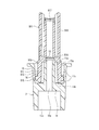
- FIG. 1A is a perspective view of a container-side connector provided with a female connector to which a cap of the present invention is attached.
- FIG. 1B is a cross-sectional perspective view of the container-side connector along the first cross section.
- FIG. 1C is a cross-sectional perspective view of the container-side connector along the second cross-section.
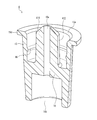
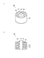
- FIG. 2A is a perspective view of a cap according to Embodiment 1 of the present invention.
- FIG. 2B is a cross-sectional perspective view of the cap according to Embodiment 1 of the present invention.
- FIG. 3A is a perspective view illustrating a state in which the cap according to the first embodiment of the present invention is attached to the female connector.
- FIG. 3B is a cross-sectional view showing a state in which the cap according to Embodiment 1 of the present invention is attached to the female connector.
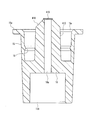
- FIG. 4 is a cross-sectional perspective view of a cap according to Embodiment 2 of the present invention.
- FIG. 5 is a cross-sectional view showing a state in which the cap according to Embodiment 2 of the present invention is attached to the female connector.
- FIG. 6A is a cross-sectional perspective view of a cap according to Embodiment 3 of the present invention.
- FIG. 6B is a plan view of the cap according to the third embodiment of the present invention.
- FIG. 7 is a cross-sectional view showing a state where the cap according to the third embodiment of the present invention is attached to the female connector.
- FIG. 8 is a cross-sectional perspective view of a cap according to Embodiment 4 of the present invention.
- FIG. 9 is sectional drawing which showed the state which mounted
- FIG. 10 is a cross-sectional view of another cap according to Embodiment 4 of the present invention.
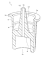
- FIG. 11 is a cross-sectional perspective view of the cap concerning Embodiment 5 of this invention.
- FIG. 12 is a cross-sectional view showing a state where the cap according to the fifth embodiment of the present invention is attached to the female connector.
- FIG. 13A is a perspective view of a female connector considered as ISO 80369-3.
- FIG. 13B is a cross-sectional view taken along a plane including the central axis of the female connector.
- FIG. 14A is a perspective view of a male connector being considered as ISO80369-3.
- FIG. 14B is a cross-sectional view taken along a plane including the central axis of the male connector.
- FIG. 15 is a diagram showing an example of the configuration of the enteral nutrition method.
- At least a part of the flow path may be formed between the insertion portion and the tubular portion.
- At least a part of the flow path may be formed in a through hole that penetrates the cap.
- the through hole may be provided, for example, in the insertion portion, or may be provided in a location other than the insertion portion of the cap (for example, a bottom plate, an outer cylinder, etc.).
- the flow path is not formed between the insertion portion and the tubular portion.
- the flow path is not formed on the outer peripheral surface of the tubular portion. Thereby, it can prevent that a liquid substance adheres to the outer peripheral surface of a tubular part after priming. For this reason, the operation which wipes off and removes the liquid substance adhering to the outer peripheral surface of the tubular portion becomes unnecessary. Moreover, possibility that a liquid material will transfer from the outer peripheral surface of a tubular part to the inner peripheral surface of the outer cylinder surrounding a male member can be reduced.
- two or more different flow paths communicating from the base end portion to the outside along the cap may be formed. Thereby, since the cross-sectional area of a flow path expands, priming can be performed in a short time.
- a liquid-tight seal may be formed between the insertion portion and the female connector.
- it can prevent that a liquid substance adheres to the outer peripheral surface of a tubular part after priming. For this reason, the operation which wipes off and removes the liquid substance adhering to the outer peripheral surface of the tubular portion becomes unnecessary.
- possibility that a liquid material will transfer from the outer peripheral surface of a tubular part to the inner peripheral surface of the outer cylinder surrounding a male member can be reduced.
- the cap can be securely attached to the female connector.
- a filter having the property of allowing gas to pass but not liquid to pass may be provided on the flow path. Thereby, it is possible to reduce the possibility of an erroneous operation of leaking the liquid material to the outside during priming.
- the cap of the present invention may further include an engaging portion that engages with the screw-like protrusion.
- a cap can be stably hold
- the operator can recognize that the cap is properly attached to the female connector from the click feeling when the engaging portion engages with the screw projection.
- the flow path communicating from the base end portion to the outside along the cap is formed.
- the cap of the present invention may further include an outer cylinder that covers an outer peripheral surface of the tubular portion when the cap is attached to the female connector.
- the outer cylinder preferably also covers a screw-like protrusion provided on the outer peripheral surface of the tubular portion.
- the tube may be a tube used for enteral nutrition.
- the base end portion is connected to a downstream end of the tube.
- the cap may be attached to the female connector when performing priming for introducing a liquid material into the tube.
- a liquid material flows from the base end portion into the flow path.
- FIG. 1A is a perspective view of the container-side connector 901.
- FIG. 1B is a cross-sectional perspective view of the container-side connector 901 along the first cross section.
- FIG. 1C is a cross-sectional perspective view of the container-side connector 901 along a second cross section orthogonal to the first cross section.
- elements corresponding to those shown in FIGS. 13A and 13B are denoted by the same reference numerals, and description thereof will be omitted.
- the container side connector 901 includes a female connector 910 shown in FIGS. 13A and 13B at one end, and a proximal end portion 917 at the other end.
- the proximal end portion 917 has a hollow cylindrical shape and communicates with a tubular portion 911 that constitutes the female connector 910.
- the inner diameter of the tubular portion 911 is larger than the inner diameter of the proximal end portion 917. Accordingly, a step 916 caused by the difference in inner diameter between the tubular portion 911 and the base end portion 917 is formed.
- the step 916 is defined at the proximal end 917 side end of the portion where the inner diameter between the tubular portion 911 and the proximal end 917 transitions. Accordingly, the inner diameter of the step 916 is smaller than the inner diameter of the tubular portion 911.
- a hollow grip portion 918 surrounds the proximal end portion 917.
- the grip portion 918 includes a pair of grip projections 918 a that protrude toward the opposite sides with respect to the base end portion 917.
- the outer peripheral surface of the grip part 918 has a flat box shape.
- the container-side connector 901 is attached to the downstream end of the tube 935. Specifically, the base end portion 917 of the container side connector 901 is inserted into the opening at the downstream end of the tube 935.
- the female connector 910 is connected to the male connector 920 at the upstream end of the catheter 945. The liquid material flows in the container side connector 901 from the base end portion 917 toward the female connector 910.
- priming is performed to fill the tube 935 with liquid before administering the liquid to the patient.
- the cap of the present invention is attached to the female connector 910 of the container-side connector 901 when priming is performed. Below, the cap of this invention is demonstrated.
- FIG. 2A is a perspective view of the cap 1 according to the first embodiment of the present invention.
- FIG. 2B is a cross-sectional perspective view of the cap 1.
- “vertical direction” and “horizontal direction” are defined based on the orientation (posture) of the cap 1 shown in FIGS. 2A and 2B. The same applies to Embodiments 2 to 5 described later. However, the “vertical direction” and “horizontal direction” do not mean the direction in actual use of the cap of the present invention.
- the cap 1 includes a hollow cylindrical outer cylinder 15.
- the cross-sectional shape of the inner peripheral surface of the outer cylinder 15 on the surface along the horizontal direction is substantially a circle.
- a bottom plate 18 is provided in the outer cylinder 15 at a position retracted from the upper opening 15 a of the outer cylinder 15.
- the bottom plate 18 is a so-called blind plate that is not provided with a through hole, and blocks communication between the upper opening 15 a and the lower opening 15 b of the outer cylinder 15.
- the insertion portion 10 protrudes upward from the center of the bottom plate 18.
- the insertion part 10 has a solid substantially cylindrical shape.
- the outer peripheral surface of the insertion portion 10 and the inner peripheral surface of the outer cylinder 15 are separated from each other.
- a rib 16 protruding toward the outer cylinder 15 is provided on the inner peripheral surface of the outer cylinder 15 at a position away from the bottom plate 18.
- the ribs 16 are annular protrusions that are continuous in the circumferential direction (the direction of rotation around the insertion portion 10).
- a flange 15d continuous in the circumferential direction protrudes outward from the upper end of the outer cylinder 15 along the radial direction.
- the material of the cap 1 is not limited, but is preferably a hard material having mechanical strength (rigidity) that is not substantially deformed by an external force.
- resin materials such as polypropylene (PP), polycarbonate (PC), polyacetal (POM), polystyrene, polyamide, polyethylene, hard polyvinyl chloride, ABS (acryl-butadiene-styrene copolymer) can be used.
- Polypropylene, polycarbonate, polyethylene and ABS are preferred.
- the cap 1 can be integrally manufactured as a single part by the injection molding method or the like using the above resin material. It is preferable that the cap 1 has transparency because the presence of a liquid substance can be confirmed through the cap 1.
- the cap 1 can be attached to and detached from the female connector 910 of the container side connector 901.
- FIG. 3A is a perspective view showing a state where the cap 1 is attached to the female connector 910 (see FIGS. 1A to 1C) of the container-side connector 901
- FIG. 3B is a cross-sectional view thereof.
- the tube 935 is connected to the base end portion 917 of the container-side connector 901.
- the tube 935 is not shown in order to simplify the drawing.
- the insertion portion 10 is inserted into the tubular portion 911.
- the outer diameter of the insertion portion 10 is smaller than the inner diameter of the tubular portion 911. For this reason, a gap 11 a is formed between the insertion portion 10 and the tubular portion 911.
- a tubular portion 911 is inserted between the insertion portion 10 and the outer cylinder 15.
- the screw-shaped protrusion 915 protruding from the outer peripheral surface 913 of the tubular portion 911 is located closer to the bottom plate 18 than the rib 16 protruding from the inner peripheral surface of the outer cylinder 15.
- the inner diameter of the rib 16 is slightly smaller than the outer diameter (thread diameter) of the screw-like protrusion 915. For this reason, the rib 16 is engaged with the screw-shaped protrusion 915. Therefore, the cap 1 does not fall off from the female connector 910.
- the bottom plate 18 and the tip of the tubular portion 911 are separated from each other. Accordingly, a gap 11b is formed between the bottom plate 18 and the tip of the tubular portion 911.
- the inner diameter of the inner peripheral surface of the outer cylinder 15 and the inner diameter of the rib 16 are both larger than the outer diameter of the outer peripheral surface 913 of the tubular portion 911. Accordingly, a gap 11 c is formed between the inner peripheral surface of the outer cylinder 15 and the outer peripheral surface 913 of the tubular portion 911.
- the screw-like projection 915 is a discontinuous screw in which the thread is divided (see FIG. 1A). Therefore, in FIG. 3B, in the gap 11c between the outer cylinder 15 and the tubular portion 911, the lower portion and the upper portion with respect to the screw projection 915 are divided portions of the screw projection 915 ( It communicates via a non-continuous part).
- the screw-like projection 915 may be a continuous screw in which a non-continuous portion is not provided on the thread, and in that case, a lower portion of the gap 11c with respect to the screw-like projection 915. And the upper portion communicate with each other through the groove of the continuous screw.
- the base end portion 917 of the container-side connector 901 communicates with the upper opening 15a of the outer cylinder 15 through the gap 11a, the gap 11b, and the gap 11c in this order.
- priming is performed as follows.
- the clamp 938 is closed with the container side connector 901 and the patient side connector 902 separated.
- the cap 1 is attached to the female connector 910 of the container-side connector 901 (see FIGS. 3A and 3B).
- a liquid material is injected into the container 931.
- the clamp 938 is opened. The liquid material passes through the tube 935 and flows into the base end portion 917 of the container-side connector 901.
- the gap 11a, the gap 11b, and the gap 11c are formed between the female connector 910 and the cap 1, and these communicate with each other.
- the liquid material reaches the opening 15a on the upper side of the outer cylinder 15 from the base end portion 917 through the gap 11a, the gap 11b, and the gap 11c in this order.
- the clamp 938 is closed.
- the cap 1 is removed from the female connector 910.
- the male connector 920 (see FIG. 15) of the patient-side connector 902 is connected to the female connector 910.
- the clamp 938 is opened, and the liquid is administered to the patient via the catheter 945.
- the insertion portion 10 when the cap 1 is attached to the female connector 910, the insertion portion 10 is inserted into the tubular portion 911.
- the gaps 11a, 11b, and 11c formed between the cap 1 and the female connector 910 constitute a flow path that connects the base end portion 917 and the outside (opening 15a). For this reason, a liquid substance can be introduced into this flow path (gap 11a, 11b, 11c) at the time of priming.
- the insertion portion 10 comes out of the tubular portion 911.
- the amount of the liquid material remaining in the tubular portion 911 is the same as or less than the volume of the flow path 11a.
- the amount of the liquid material remaining in the tubular portion 911 at the end of the priming is small. Therefore, after that, when the male member 921 (see FIGS. 14A and 14B) of the male connector 920 is inserted into the tubular portion 911, the gap 926 (see FIG. 14B) between the male member 921 and the outer cylinder 923 is inserted. The amount of liquid that flows out can be reduced. As a result, after the enteral nutrition method is completed and the female connector 910 is separated from the male connector 920, the liquid material remaining in the gap 926 between the male member 921 and the outer cylinder 923 can be reduced.
- the liquid material flows into the gap 11c during priming. Therefore, after removing the cap 1 from the female connector 910, it is preferable to wipe off and remove the liquid material attached to the outer peripheral surface 913 of the tubular portion 911 of the female connector 910. Thereby, after that, when the male connector 920 is connected to the female connector 910, the possibility that the liquid material is transferred to the inner peripheral surface of the outer cylinder 923 can be reduced. This is advantageous in maintaining good hygiene of the male connector 920 after the enteral nutrition method is completed. Since the outer peripheral surface 913 is exposed to the outside, it is easy to wipe off and remove the liquid material adhering to the outer peripheral surface 913 of the tubular portion 911.
- the rib 16 protruding from the inner peripheral surface of the outer cylinder 15 functions as an engaging portion that engages with the screw-shaped protrusion 915 of the female connector 910.
- the force that pushes the cap 1 toward the female connector 910 to attach the cap 1 to the female connector 910 slightly increases when the rib 16 gets over the screwing protrusion 915, and the rib 16 gets over the screwing protrusion 915. Immediately after that, it decreases rapidly. The operator can feel the change in force as a click feeling, and thereby recognize that the cap 1 is properly attached to the female connector 910.
- the ribs 16 engage with the screw-like projections 915, so that the pressure of the liquid material flowing into the gaps 11a, 11b, 11c due to gravity or vibration or during priming This prevents the cap 1 from falling off the female connector 910.
- the cap 1 can be left attached to the female connector 910 when priming and enteral nutrition are not performed.
- the outer cylinder 15 covers almost the entire outer peripheral surface 913 (including the screw-shaped protrusion 915) of the tubular portion 911, so that the outer peripheral surface 913 of the tubular portion 911 is prevented from becoming dirty. Can do.
- the bottom plate 18 prevents the inner peripheral surface 912 of the tubular portion 911 from becoming dirty.
- a flow path (see FIG. 3B) along the cap 1 that allows the base end portion 917 to communicate with the outside world when the cap 1 is attached to the female connector 910 may be formed by a method other than the above embodiment.
- the outer peripheral surface of the insertion portion 10 may be a male tapered surface whose diameter and taper angle coincide with those of the inner peripheral surface 912 of the tubular portion 911.
- the outer peripheral surface of the insertion portion 10 may be in close contact with the inner peripheral surface 912 of the tubular portion 911.
- a groove extending from the distal end of the insertion portion 10 to the bottom plate 18 along the longitudinal direction of the insertion portion 10 may be formed on the outer peripheral surface of the insertion portion 10. This groove can be used as a gap 11 a between the insertion portion 10 and the tubular portion 911.
- the distal end of the tubular portion 911 may abut on the bottom plate 18.
- a groove extending from the insertion portion 10 to the outer cylinder 15 may be formed in the bottom plate 18. This groove can be used as a gap 11b between the bottom plate 18 and the tip of the tubular portion 911.
- the length and outer diameter of the insertion portion 10 can be freely set as long as a liquid material can flow between the insertion portion 10 and the tubular portion 911 during priming. As the length of the insertion portion 10 is longer and the outer diameter of the insertion portion 10 is larger, the amount of liquid material remaining in the tubular portion 911 after the cap 1 is removed from the female connector 910 can be reduced. This is advantageous in reducing the amount of liquid remaining in the gap 926 (see FIG. 14B) between the male member 921 and the outer cylinder 923 upon completion of enteral nutrition. On the other hand, if the insertion portion 10 is long and its outer diameter is large, the cross-sectional area of the flow path through which the liquid material flows during priming becomes small, so that a long time is required for priming.
- the volume of the portion of the insertion portion 10 present in the tubular portion 911 is more than half of the volume of the lumen of the tubular portion 911, and more than two-thirds, In particular, it is preferably 3/4 or more.
- the length of the insertion portion 10 when the cap 1 is attached to the female connector 910, the distal end of the insertion portion 10 reaches the vicinity of the step 916 at the boundary portion between the tubular portion 911 and the base end portion 917. Preferably reached.
- the outer cylinder 15 of the cap 1 extends below the bottom plate 18 (on the side opposite to the insertion portion 10). However, even if the portion below the bottom plate 18 of the outer cylinder 15 is omitted. Good.
- the rib 16 as the engaging portion protruding from the inner peripheral surface of the outer cylinder 15 can have any shape other than the above-described embodiment as long as it can engage with the screw-shaped protrusion 915 of the female connector 910.
- the engaging portion may be a discontinuous protrusion divided in the circumferential direction.
- the engaging portion may constitute a screw thread (female screw) that is screwed with the screw-shaped protrusion 915.
- the fact that the engaging portion is an annular rib 16 that is continuous in the circumferential direction as in the present embodiment means that the rotational direction of the cap 1 is even when the screw-like projection 915 is a discontinuous screw as shown in FIG. 1A. This is advantageous because the engaging portion can be reliably engaged with the screw-shaped protrusion 915 regardless of the position of the screw.
- the plurality of protrusions 15 c formed on the outer peripheral surface of the outer cylinder 15 are effective for the operator to firmly hold the cap 1 when the cap 1 is attached to the female connector 910.
- any shape other than the protrusions 15c may be provided on the outer peripheral surface of the outer cylinder 15.
- the protrusion 15c may be omitted.
- the outer peripheral surface of the outer cylinder 15 does not need to be a substantially cylindrical surface, and may be a regular polygonal column surface such as a regular octagonal column surface or a regular hexagonal column surface.
- the flange 15d can be used for an operator to apply force to the cap 1 when the cap 1 is attached to and detached from the female connector 910.
- the flange 15d is provided at the upper end of the outer cylinder 15.
- the position of the flange 15d is not limited to this, and may be provided at an arbitrary position between the upper end and the lower end of the outer cylinder 15. it can.
- the flange 15 can be provided at the lower end of the outer cylinder 15, and this configuration is advantageous for applying a force away from the female connector 910 to the cap 1 when the cap 1 is separated from the female connector 910. It is possible.
- Two or more flanges 15d may be provided at different positions in the vertical direction.
- the flange 15d may be an annular protrusion that is continuous in the circumferential direction as in the above-described embodiment, but is not limited thereto, and may be composed of, for example, one or more protrusions that are not continuous in the circumferential direction. . In the present invention, the flange 15d may be omitted.
- FIG. 4 is a cross-sectional perspective view of the cap 2 according to the second embodiment of the present invention.
- the cap 2 of the second embodiment is different from the cap 1 of the first embodiment in that a through hole 10 a is formed in the insertion portion 10 and the bottom plate 18.
- the second embodiment will be described with a focus on differences from the first embodiment.
- the same reference numerals are given to the same elements as those in the drawings referred to in the first embodiment, and description thereof will be omitted.
- the through-hole 10a penetrates the insertion part 10 and the bottom plate 18 in the vertical direction. Accordingly, the upper opening 15a and the lower opening 15b of the outer cylinder 15 communicate with each other through the through hole 10a.
- the cap 2 can be attached to and detached from the female connector 910 of the container side connector 901.
- FIG. 5 is a cross-sectional view showing a state where the cap 2 is attached to the female connector 910 (see FIGS. 1A to 1C) of the container-side connector 901.
- a tube 935 is connected to the base end portion 917 of the container-side connector 901.
- the tube 935 is not shown in order to simplify the drawing.
- the insertion portion 10 is inserted into the tubular portion 911. Further, a gap 11a, a gap 11b, and a gap 11c are formed between the cap 2 and the female connector 910. Therefore, the base end portion 917 of the container side connector 901 communicates with the opening 15a on the upper side of the outer cylinder 15 through the gap 11a, the gap 11b, and the gap 11c in this order.
- the base end portion 917 of the container side connector 901 communicates with the lower opening 15 b of the outer cylinder 15 through the insertion portion 10 and the through hole 10 a provided in the bottom plate 18.
- the priming method using the cap 2 is substantially the same as in the first embodiment.
- the through hole 10 a is formed in the insertion portion 10 and the bottom plate 18. Therefore, when the clamp 938 is opened with the cap 2 attached to the female connector 910, the liquid material passes through the gap 11a, the gap 11b, and the gap 11c in this order from the base end portion 917 to the opening 15a on the upper side of the outer cylinder 15. In addition to reaching, the base end portion 917 also reaches the lower opening 15b of the outer cylinder 15 through the through hole 10a. After confirming that the liquid has reached the opening 15a and / or the opening 15b, the clamp 938 is closed. Thereafter, the cap 2 is removed from the female connector 910 as in the first embodiment.
- the amount of the liquid material remaining in the tubular portion 911 is the same as or less than the volume of the flow path 11a. Therefore, after that, when the male member 921 (see FIGS. 14A and 14B) is inserted into the tubular portion 911, the liquid material that flows out to the gap 926 (see FIG. 14B) between the male member 921 and the outer cylinder 923 is used. The amount can be reduced. As a result, after the enteral nutrition method is completed and the female connector 910 is separated from the male connector 920, the liquid material remaining in the gap 926 between the male member 921 and the outer cylinder 923 can be reduced.
- the second embodiment is the same as the first embodiment except for the above.
- the description of the first embodiment is also applied to the second embodiment.
- FIG. 6A is a cross-sectional perspective view of the cap 3 according to the third embodiment of the present invention.
- FIG. 6B is a plan view of the cap 3.
- the cap 3 according to the third embodiment is different from the cap 1 according to the first embodiment in that a through hole 18 a is formed in the bottom plate 18.
- the third embodiment will be described with a focus on differences from the first embodiment.
- the same elements as those in the drawings referred to in the first embodiment are denoted by the same reference numerals, and description thereof is omitted.
- Two through holes 18a are formed at substantially symmetrical positions with respect to the insertion portion 10 of the bottom plate 18. Accordingly, the upper opening 15a and the lower opening 15b of the outer cylinder 15 communicate with each other through the through hole 18a.
- the cap 3 can be attached to and detached from the female connector 910 of the container side connector 901.
- FIG. 7 is a cross-sectional view showing a state in which the cap 3 is attached to the female connector 910 (see FIGS. 1A to 1C) of the container-side connector 901.
- FIG. 7 Actually, the tube 935 is connected to the base end portion 917 of the container-side connector 901. However, in FIG. 7, the tube 935 is not shown in order to simplify the drawing.
- the insertion portion 10 is inserted into the tubular portion 911.
- a gap 11a, a gap 11b, and a gap 11c are formed between the cap 3 and the female connector 910. Therefore, the base end portion 917 of the container side connector 901 communicates with the opening 15a on the upper side of the outer cylinder 15 through the gap 11a, the gap 11b, and the gap 11c in this order.
- the base end portion 917 of the container side connector 901 communicates with the lower opening 15b of the outer cylinder 15 through the gap 11a and the through hole 18a provided in the bottom plate 18. .
- the priming method using the cap 3 is substantially the same as in the first embodiment.
- a through hole 18 a is formed in the bottom plate 18. Therefore, when the clamp 938 is opened with the cap 3 attached to the female connector 910, the liquid material passes through the gap 11a, the gap 11b, and the gap 11c in this order from the base end portion 917 to the upper opening 15a of the outer cylinder 15. In addition to reaching, the base end 917 also reaches the lower opening 15b of the outer cylinder 15 through the gap 11a and the through hole 18a in this order. After confirming that the liquid has reached the opening 15a and / or the opening 15b, the clamp 938 is closed. Thereafter, the cap 3 is removed from the female connector 910 as in the first embodiment.
- the cap 3 when the cap 3 is attached to the female connector 910, in addition to the first flow path communicating from the base end portion 917 to the outside (opening 15a) through the gaps 11a, 11b, and 11c, A second flow path is formed which communicates from the base end portion 917 to the outside (opening 15b) through the gap 11a and the through hole 18a. For this reason, a liquid substance can be introduced into these two flow paths (gap 11a, 11b, 11c; gap 11a, through hole 18a) during priming. Thereafter, the cap 3 is removed from the female connector 910. Similar to the first embodiment, the amount of the liquid material remaining in the tubular portion 911 is the same as or less than the volume of the flow path 11a.
- the liquid material that flows out to the gap 926 (see FIG. 14B) between the male member 921 and the outer cylinder 923 is used.
- the amount can be reduced.
- the enteral nutrition method is completed and the female connector 910 is separated from the male connector 920, the liquid material remaining in the gap 926 between the male member 921 and the outer cylinder 923 can be reduced.
- the two through holes 18a are formed in the bottom plate 18.
- the number of the through holes 18a is not limited to two, but may be one or three or more. Also good.
- the through hole 18a is formed in the bottom plate 18.
- the outer cylinder 15 is provided with a through hole that penetrates the outer cylinder 15 in the radial direction. Also good.
- the through-hole is provided, for example, in a region of the outer cylinder 15 between the bottom plate 18 and the rib 16, in particular, a region between the bottom plate 18 and the screw-shaped protrusion 915 so as to communicate with the gap 11 b or the gap 11 c. it can.
- the number of through holes may be one or two or more.
- the cap 1 according to the first embodiment and the cap 2 according to the second embodiment may be provided with a through hole in the outer cylinder 15.
- the third embodiment is the same as the first embodiment except for the above.
- the description of the first embodiment is also applied to the third embodiment.
- the through hole 18a of the bottom plate 18 described in the third embodiment may be applied to the cap 2 of the second embodiment.
- the cap when the cap is attached to the female connector 910, three flow paths that connect the base end portion 917 and the outside world are formed. Therefore, since the cross-sectional area of the flow path is enlarged, priming can be performed in a shorter time.
- FIG. 8 is a cross-sectional perspective view of the cap 4 according to the fourth embodiment of the present invention.
- the cap 4 of the fourth embodiment is different from the cap 1 of the first embodiment in the following two points.
- a male taper surface whose outer diameter and taper angle coincide with the female taper surface (see FIGS. 13A and 13B) formed on the inner peripheral surface 912 of the tubular portion 911 of the female connector 910 on the outer peripheral surface 412 of the insertion portion 410. Is formed.
- a through hole 10 a similar to that of the second embodiment is formed in the insertion portion 410 and the bottom plate 18.
- the fourth embodiment will be described with a focus on differences from the first embodiment.
- the same reference numerals are given to the same elements as those in the drawings referred to in the first embodiment, and description thereof is omitted.
- the outer peripheral surface 412 of the insertion part 410 is the same male tapered surface as the outer peripheral surface 922 (see FIGS. 14A and 14B) of the male member 921 of the male connector 920 that matches the female connector 910. Therefore, when the insertion portion 410 is inserted into the tubular portion 911 of the female connector 910, the outer peripheral surface 412 of the insertion portion 410 and the inner peripheral surface 912 of the tubular portion 911 are fitted in a liquid-tight manner, and a liquid-tight state is formed therebetween. A seal is formed.
- the through-hole 10a penetrates the insertion portion 410 and the bottom plate 18 in the vertical direction. Accordingly, the upper opening 15a and the lower opening 15b of the outer cylinder 15 communicate with each other through the through hole 10a.
- the cap 4 can be attached to and detached from the female connector 910 of the container side connector 901.
- FIG. 9 is a cross-sectional view showing a state in which the cap 4 is attached to the female connector 910 (see FIGS. 1A to 1C) of the container side connector 901.
- a tube 935 is connected to the base end portion 917 of the container-side connector 901.
- the tube 935 is not shown in order to simplify the drawing.
- the insertion portion 410 is inserted into the tubular portion 911.
- the outer peripheral surface 412 of the insertion portion 410 and the inner peripheral surface 912 of the tubular portion 911 are in close contact, and a liquid-tight seal is formed between them.
- the distal end of the insertion portion 410 reaches a step 916 at the boundary between the tubular portion 911 and the proximal end portion 917. Therefore, the gap 11a formed in the first to third embodiments does not substantially exist between the insertion portion 10 and the tubular portion 911.
- a gap 11b and a gap 11c are formed between the cap 4 and the female connector 910.
- the base end portion 917 of the container side connector 901 does not communicate with the upper opening 15 a of the outer cylinder 15.
- the base end portion 917 of the container-side connector 901 communicates with the lower opening 15b of the outer cylinder 15 through the insertion portion 410 and the through hole 10a provided in the bottom plate 18.
- the priming method using the cap 4 is substantially the same as in the first embodiment.
- the flow path from the base end portion 917 to the upper opening 15a is blocked. Instead, there is a flow path from the base end portion 917 to the lower opening 15b through the through hole 10a. Accordingly, when the clamp 938 is opened with the cap 4 attached to the female connector 910, the liquid material reaches the lower opening 15b of the outer cylinder 15 from the base end portion 917 through the through hole 10a. After confirming that the liquid has reached the opening 15b, the clamp 938 is closed. Thereafter, the cap 4 is removed from the female connector 910 as in the first embodiment.
- the cap 4 when the cap 4 is attached to the female connector 910, a flow path that communicates from the base end portion 917 to the outside (opening 15b) through the through hole 10a is formed. For this reason, a liquid substance can be introduced into the flow path (through hole 10a) during priming. Thereafter, the cap 4 is removed from the female connector 910.
- the gap 11a is not substantially formed in the tubular portion 911.
- the liquid material in the through hole 10 a is removed from the tubular portion 911 together with the cap 4. Therefore, almost no liquid material remains in the tubular portion 911 after the cap 4 is removed. Therefore, after that, when the male member 921 (see FIGS.
- the liquid material does not flow into the gap 11b and the gap 11c during priming. That is, the flow path through which the liquid material flows is not formed on the outer peripheral surface 913 of the tubular portion 911.
- the liquid material does not adhere to the outer peripheral surface 913 of the tubular portion 911 after priming.
- the operation preferably performed in the first to third embodiments of wiping and removing the liquid material adhering to the outer peripheral surface 913 of the tubular portion 911 is unnecessary in the fourth embodiment. is there.
- the liquid material may be transferred from the outer peripheral surface 913 of the tubular portion 911 to the inner peripheral surface of the outer cylinder 923. Very low. This is advantageous in maintaining good hygiene of the male connector 920 after the enteral nutrition method is completed.
- the distal end of the insertion portion 410 when the cap 4 is attached to the female connector 910, the distal end of the insertion portion 410 reaches the step 916. However, the distal end of the insertion portion 410 may not reach the step 916. Even if the insertion portion 410 is shorter than the depth of the tubular portion 911, it is possible to form a liquid-tight seal between the outer peripheral surface 412 of the insertion portion 410 and the inner peripheral surface 912 of the tubular portion 911. However, the shorter the insertion portion 410, the more liquid is left in the tubular portion 911 after the cap 4 is removed from the female connector 910.
- the insertion depth of the insertion portion 410 with respect to the tubular portion 911 is the depth of the tubular portion 911 (the distance from the distal end of the tubular portion 911 to the step 916).
- the depth of the tubular portion 911 is the distance from the distal end of the tubular portion 911 to the step 916.
- the insertion portion 410 and the container-side connector 901 are fitted in a liquid-tight manner. Therefore, the bond strength between the two is relatively high. If the cap 4 does not fall off the female connector 910 during priming, the rib 16 that engages with the screw-shaped protrusion 915 can be omitted. Furthermore, the outer cylinder 15 and the bottom plate 18 can be omitted. In this case, the insertion portion 410 can be extended downward to provide a holding portion for the operator to hold the cap 4.
- a ventilation filter 419 may be provided so as to close the through hole 10a.
- the ventilation filter 419 is a filter having a property of allowing gas to pass but not allowing liquid to pass through, and may be referred to as a “hydrophobic filter”.
- the ventilation filter 419 is preferably provided at the distal end of the insertion portion 410 as shown in FIG. Thereby, since it can prevent that a liquid substance flows in into the through-hole 10a, the quantity of the liquid substance discarded wastefully can be decreased.
- the position where the ventilation filter 419 is provided is not limited to this, and may be, for example, an opening on the lower side (bottom plate 18 side) of the through hole 10a or an arbitrary position in the through hole 10a. Good.
- the fourth embodiment is the same as the first embodiment except for the above.
- the description of the first embodiment is also applied to the fourth embodiment.
- FIG. 11 is a cross-sectional perspective view of the cap 5 according to the fifth embodiment of the present invention.
- the cap 5 of the fifth embodiment is different from the cap 4 of the fourth embodiment with respect to the shape of the outer peripheral surface 512 of the insertion portion 510.
- the fifth embodiment will be described with a focus on differences from the fourth embodiment.
- the same reference numerals are given to the same elements as those in the drawings referred to in the fourth embodiment, and description thereof will be omitted.
- the outer peripheral surface 512 of the insertion portion 510 is a tapered surface (male tapered surface) whose outer diameter decreases as it approaches the tip.
- the male tapered surface of the outer peripheral surface 512 has a larger taper angle than the male tapered surface provided on the outer peripheral surface 412 of the insertion portion 410 of the fourth embodiment.
- the insertion portion 510 extends higher upward than the insertion portion 410 of the fourth embodiment.
- the insertion part 510 and the bottom plate 18 are formed with the same through-hole 10a as in the second and fourth embodiments.
- the through hole 10a penetrates the insertion portion 510 and the bottom plate 18 in the vertical direction. Accordingly, the upper opening 15a and the lower opening 15b of the outer cylinder 15 communicate with each other through the through hole 10a.
- the cap 5 can be attached to and detached from the female connector 910 of the container side connector 901.
- FIG. 12 is a cross-sectional view showing a state where the cap 5 is attached to the female connector 910 (see FIGS. 1A to 1C) of the container-side connector 901.
- FIG. 12 Actually, the tube 935 is connected to the base end portion 917 of the container-side connector 901. However, in FIG. 12, the tube 935 is not shown in order to simplify the drawing.
- the insertion portion 510 is inserted into the tubular portion 911.
- a gap 11a, a gap 11b, and a gap 11c are formed between the cap 5 and the female connector 910.
- the outer peripheral surface 512 of the insertion portion 510 is fitted to the step 916 at the boundary portion between the tubular portion 911 and the base end portion 917, and the liquid-tightness is between the insertion portion 510 and the step 916.
- a seal is formed. Therefore, the base end portion 917 of the container side connector 901 does not communicate with the gap 11a. Accordingly, the base end portion 917 does not communicate with the upper opening 15 a of the outer cylinder 15.
- the base end portion 917 of the container-side connector 901 is inserted into the lower opening 15b of the outer cylinder 15 via the insertion portion 510 and the through hole 10a provided in the bottom plate 18. Communicate.
- the priming method using the cap 5 is substantially the same as in the fourth embodiment. Similarly to the fourth embodiment, the flow path from the base end portion 917 to the upper opening 15a is also blocked in the fifth embodiment. Instead, there is a flow path from the base end portion 917 to the lower opening 15b through the through hole 10a. Accordingly, when the clamp 938 is opened with the cap 5 attached to the female connector 910, the liquid material passes from the base end portion 917 through the through hole 10a to the lower opening 15b of the outer cylinder 15 from the base end portion 917. To reach. After confirming that the liquid has reached the opening 15b, the clamp 938 is closed. Thereafter, the cap 5 is removed from the female connector 910.
- the insertion portion 510 and the step 916 are fitted in a liquid-tight manner. Therefore, the liquid material does not flow into the gap 11a between the insertion portion 10 and the tubular portion 911 during priming.
- the liquid material in the through hole 10 a is removed from the tubular portion 911 together with the cap 5. Therefore, as in the fourth embodiment, the liquid material hardly remains in the tubular portion 911 after the cap 5 is removed. Therefore, after that, when the male member 921 (see FIGS. 14A and 14B) is inserted into the tubular portion 911, almost no liquid material is present in the gap 926 (see FIG. 14B) between the male member 921 and the outer cylinder 923. It will not flow out.
- the liquid material remaining in the gap 926 between the male member 921 and the outer cylinder 923 is further increased than in the first to third embodiments. Can be reduced.
- the liquid material does not flow into the gap 11b and the gap 11c during priming. That is, the flow path through which the liquid material flows is not formed on the outer peripheral surface 913 of the tubular portion 911.
- the liquid material does not adhere to the outer peripheral surface 913 of the tubular portion 911 after priming. For this reason, after removing the cap 5 from the female connector 910, the operation of wiping and removing the liquid material adhering to the outer peripheral surface 913 of the tubular portion 911 is unnecessary.
- the liquid material may be transferred from the outer peripheral surface 913 of the tubular portion 911 to the inner peripheral surface of the outer cylinder 923. Very low. This is advantageous in maintaining good hygiene of the male connector 920 after the enteral nutrition method is completed.
- a single male tapered surface is formed on the outer peripheral surface 512 of the insertion portion 510 in the entire region from the bottom plate 18 to the tip of the insertion portion 510.
- the shape of the outer peripheral surface 512 of the insertion part 510 is not limited to this. If a liquid-tight seal is formed between the insertion portion 510 and the inner peripheral surface of the container-side connector 901, the shape of the outer peripheral surface 512 can be arbitrarily changed.
- a male taper surface is formed only in a portion that fits in the step 916 and a portion in the vicinity of the outer peripheral surface of the insertion portion 510, and a portion closer to the bottom plate 18 can have an arbitrary shape (eg, a cylindrical surface) .
- the position where the liquid-tight seal is formed is not limited to the step 916. It may be in the tubular portion 911 in front of the step 916, or in the proximal end portion 917 in the back of the step 916.
- the formation of a liquid-tight seal at the step 916 or the base end portion 917 is preferable because the amount of liquid remaining in the tubular portion 911 after the cap 5 is removed can be reduced.
- the outer peripheral surface of the insertion portion 510 does not need to be in direct contact with the inner peripheral surface of the container-side connector 901.
- a sealing member may be provided on the outer peripheral surface of the insertion portion 510, and the sealing member may be brought into liquid-tight contact with the inner peripheral surface of the container side connector 901.
- the method of providing the seal member is arbitrary.
- an O-ring may be attached to the outer peripheral surface of the insertion portion 510, and rubber such as silicone rubber or elastomer having rubber elasticity such as thermoplastic elastomer is inserted by two-color molding. You may integrally provide in the outer peripheral surface of the part 510.
- Embodiment 5 is the same as Embodiments 1 and 4 except for the above.
- the description of the first and fourth embodiments is also applied to the fifth embodiment.
- the configuration of the container-side connector provided with the female connector 910 to which the cap of the present invention is attached is not limited to FIGS. 1A to 1C.
- a female connector 910 conforming to ISO 80369-3 may be provided, and a base end portion 917 communicating with the tubular portion 911 of the female connector 910 may be provided.
- the configuration of parts not defined in ISO 80369-3 can be arbitrarily changed.
- the inner diameter of the base end portion 917 does not need to be the same as the inner diameter of the step 916 and may be larger than the inner diameter of the tubular portion 911.
- a step 916 having a smaller diameter than the tubular portion 911 is provided between the tubular portion 911 and the base end portion 917.
- the configuration of the grip portion 918 can also be arbitrarily changed.
- the shape of the grip protrusion 918a may be changed, or the grip protrusion 918a may be omitted.
- the grip portion 918 including the grip protrusion 918a may be omitted.
- the configuration of the tube connected to the base end 917 of the container-side connector is not limited to that shown in FIG. Any tube can be connected to the proximal end 917.
- a known clamp for opening and closing the flow path of the tube 935 may be provided in the tube 935. In this case, the start / stop switching of the introduction of the liquid material into the tube 935 can be performed using the clamp.
- the male connector 920 to which the female connector 910 is connected is provided at the upstream end of the catheter 945 placed in the patient, but the present invention is not limited to this.
- a flexible tube may be connected to the upstream end of the catheter placed in the patient, and a male connector 920 may be provided at the upstream end of the tube.
- the present invention can be preferably used for priming a tube provided with a female connector (see FIGS. 13A and 13B) compliant with ISO 80369-3 at the downstream end. Among them, it can be preferably used for priming in the medical field, particularly enteral nutrition.
Landscapes
- Health & Medical Sciences (AREA)
- Heart & Thoracic Surgery (AREA)
- Pulmonology (AREA)
- Engineering & Computer Science (AREA)
- Anesthesiology (AREA)
- Biomedical Technology (AREA)
- Hematology (AREA)
- Life Sciences & Earth Sciences (AREA)
- Animal Behavior & Ethology (AREA)
- General Health & Medical Sciences (AREA)
- Public Health (AREA)
- Veterinary Medicine (AREA)
- Infusion, Injection, And Reservoir Apparatuses (AREA)
Abstract
In the present invention, a female connector (910) is provided with a tube-like section (911) having a tubular shape. A screw-like protrusion (915) is provided on the outer circumferential surface (913) of the tube-like section, and a tapered surface which has an inner diameter gradually increasing toward the tip thereof is provided on the inner circumferential surface (912) of the tube-like section. The tube-like section communicates with a base end section (917) to which a flexible tube (935) is connected. This cap (1) of the present invention is detachably attached to the above-described female connector (910). The cap is provided with an insertion section (10). When the cap is attached to the female connector, the insertion section is inserted into the tube-like section, and flow passages (11a, 11b, 11c) communicating with the outside environment are formed along the cap from the base end.
Description
本発明は、メスコネクタに着脱可能に装着される、メスコネクタ用のキャップに関する。特に、下流側端にメスコネクタが設けられたチューブ内に液状物を導入するプライミング操作を行う際に、当該メスコネクタに装着して好ましく使用することができるキャップに関する。
The present invention relates to a female connector cap that is detachably attached to the female connector. In particular, the present invention relates to a cap that can be attached to the female connector and used preferably when performing a priming operation for introducing a liquid material into a tube having a female connector at the downstream end.
食事を口から摂れなくなった患者に栄養剤や薬剤等を含む液状物を投与する方法として経腸栄養法が知られている。経腸栄養法では、カテーテルは体外から消化管(例えば胃)内に挿入した状態で患者に留置される。カテーテルとしては、患者の鼻から挿入する経鼻カテーテルや、患者の腹に形成された胃ろうに挿入するPEG(Percutaneous Endoscopic Gastrostomy)カテーテル等が知られている。カテーテルを介して栄養剤、流動食(一般に「経腸栄養剤」と呼ばれる)、又は薬剤などの液状物が患者に投与される。患者に液状物を投与する際には、液状物を貯留した容器に接続されたチューブの下流側端に設けられたコネクタ(以下「容器側コネクタ」という)と、患者に留置されたカテーテルの上流側端に設けられたコネクタ(以下「患者側コネクタ」という)とを接続する。従来、容器側コネクタとしてオスコネクタが、また、患者側コネクタとしてメスコネクタが、それぞれ用いられていた(例えば特許文献1参照)。
Enteral nutrition is known as a method of administering liquids containing nutrients and drugs to patients who are unable to take their meals from their mouths. In enteral nutrition, a catheter is placed in a patient while inserted from the outside of the body into the digestive tract (for example, the stomach). Known catheters include a nasal catheter that is inserted from the patient's nose, a PEG (Percutaneous Endoscopic Gastrostomy) catheter that is inserted into a gastric fistula formed on the patient's abdomen, and the like. A liquid such as a nutrient, liquid food (commonly referred to as “enteral nutrient”), or a drug is administered to a patient via a catheter. When administering a liquid substance to a patient, a connector (hereinafter referred to as “container-side connector”) provided at the downstream end of a tube connected to a container storing the liquid substance, and an upstream of a catheter placed in the patient A connector provided at the side end (hereinafter referred to as “patient-side connector”) is connected. Conventionally, a male connector has been used as a container-side connector, and a female connector has been used as a patient-side connector (see, for example, Patent Document 1).
近年、経腸栄養以外の分野で使用されるコネクタとの誤接続を防止するために、容器側コネクタとして図13A及び図13Bに示すメスコネクタ910が、また、患者側コネクタとして図14A及び図14Bに示すオスコネクタ920が、栄養系の医療機器に関する国際規格ISO80369-3として国際標準化することが検討されている。
In recent years, in order to prevent erroneous connection with connectors used in fields other than enteral nutrition, the female connector 910 shown in FIGS. 13A and 13B is used as a container-side connector, and FIGS. 14A and 14B are used as patient-side connectors. It is considered that the male connector 920 shown in FIG. 1 is internationally standardized as an international standard ISO80369-3 regarding nutritional medical devices.
図13A及び図13Bに示すメスコネクタ(容器側コネクタ)910は、中空円筒形状の管状部(メス部材)911を有する。管状部911の内周面912は、先端に近づくにしたがって内径が大きくなるテーパ面(いわゆるメステーパ面)である。管状部911の外周面913には螺状突起(雄ネジ)915が形成されている。図13A及び図13Bでは、螺状突起915は、ネジ山が分断された不連続ネジであるが、ISO80369-3ではネジ山が連続した連続ネジ(一般的な雄ネジ)も許容されている。
A female connector (container-side connector) 910 shown in FIGS. 13A and 13B has a hollow cylindrical tubular portion (female member) 911. The inner peripheral surface 912 of the tubular portion 911 is a tapered surface (so-called female tapered surface) whose inner diameter increases as it approaches the tip. A screw-shaped projection (male thread) 915 is formed on the outer peripheral surface 913 of the tubular portion 911. In FIG. 13A and FIG. 13B, the screw-like projection 915 is a discontinuous screw in which the screw thread is divided. However, in ISO 80369-3, a continuous screw (a general male screw) in which the screw thread is continuous is also allowed.
図14A及び図14Bに示すオスコネクタ(患者側コネクタ)920は、筒形状のオス部材921と、オス部材921を取り囲む外筒923とを有する。オス部材921の外周面922は、先端に近づくにしたがって外径が小さくなるテーパ面(いわゆるオステーパ面)である。オス部材921には、その長手方向に沿ってオス部材911を貫通する流路927が形成されている。外筒923のオス部材911に対向する内周面には雌ネジ925が形成されている。
A male connector (patient side connector) 920 shown in FIG. 14A and FIG. 14B has a cylindrical male member 921 and an outer cylinder 923 surrounding the male member 921. The outer peripheral surface 922 of the male member 921 is a tapered surface (so-called male tapered surface) whose outer diameter decreases as it approaches the tip. The male member 921 is formed with a flow path 927 that penetrates the male member 911 along the longitudinal direction thereof. A female screw 925 is formed on the inner peripheral surface of the outer cylinder 923 facing the male member 911.
メスコネクタ910とオスコネクタ920とは、オス部材921を管状部911に挿入し、且つ、螺状突起915と雌ネジ925とを螺合させることにより接続される。管状部911の内周面912とオス部材921の外周面922とは、径及びテーパ角度が一致するテーパ面であるから、両者は液密な面接触をする。互いに螺合する螺状突起915及び雌ネジ925は、メスコネクタ910とオスコネクタ920との接続状態をロックするためのロック機構を構成する。メスコネクタ910とオスコネクタ920とは、液密性(液状物に圧力を加えてもオスコネクタとメスコネクタとの接続部分から液状物が漏れ出さない性質)と接続強度(接続されたオスコネクタとメスコネクタとが引張り力を加えても分離しない性質)に優れた接続を提供する。
The female connector 910 and the male connector 920 are connected by inserting the male member 921 into the tubular portion 911 and screwing the screw-shaped protrusion 915 and the female screw 925 together. Since the inner peripheral surface 912 of the tubular portion 911 and the outer peripheral surface 922 of the male member 921 are tapered surfaces having the same diameter and the same taper angle, they are in liquid-tight surface contact. The screw-shaped protrusion 915 and the female screw 925 that are screwed together constitute a lock mechanism for locking the connection state between the female connector 910 and the male connector 920. The female connector 910 and the male connector 920 are liquid-tight (property that liquid does not leak out from the connecting portion between the male connector and the female connector even when pressure is applied to the liquid) and connection strength (connected male connector and Provides excellent connection with the female connector that does not separate even when a tensile force is applied.
図15は、メスコネクタ910及びオスコネクタ920を用いた経腸栄養法の構成の一例を示す。患者に投与される液状物は、容器931に貯留される。容器931のポート932にはチューブ935が接続される。チューブ935は柔軟性を有するチューブからなる。チューブ935の上流側端には、ポート932に接続されるコネクタ936が設けられる。チューブ935の途中には、液状物の流れを可視化するための点滴筒937、液状物の流量を調整するためのクレンメ938が設けられている。チューブ935の下流側端には容器側コネクタ901が設けられている。容器側コネクタ901は、図13A及び図13Bに示したメスコネクタ910を備える。カテーテル945は、その上流側端に患者側コネクタ902を備える。患者側コネクタ902は、図14A及び図14Bに示したオスコネクタ920を備える。カテーテル945の下流側端(図示せず)は患者の消化管内に挿入されている。
FIG. 15 shows an example of the configuration of an enteral nutrition method using a female connector 910 and a male connector 920. The liquid substance to be administered to the patient is stored in the container 931. A tube 935 is connected to the port 932 of the container 931. The tube 935 is a flexible tube. A connector 936 connected to the port 932 is provided at the upstream end of the tube 935. In the middle of the tube 935, a drip tube 937 for visualizing the flow of the liquid material and a clamp 938 for adjusting the flow rate of the liquid material are provided. A container-side connector 901 is provided at the downstream end of the tube 935. The container-side connector 901 includes the female connector 910 shown in FIGS. 13A and 13B. The catheter 945 includes a patient-side connector 902 at its upstream end. The patient-side connector 902 includes the male connector 920 shown in FIGS. 14A and 14B. The downstream end (not shown) of the catheter 945 is inserted into the patient's digestive tract.
経腸栄養は概略以下のようにして行う。容器側コネクタ901と患者側コネクタ902とを分離した状態で、クレンメ938でチューブ935の流路を閉じる。次いで、容器931に液状物を注入する。次いで、「プライミング」を行う。即ち、クレンメ938を開いてチューブ935内に液状物を導入する。液状物が容器側コネクタ901を構成するメスコネクタ910の管状部911(図13A及び図13B参照)まで導入されたことを確認した後、クレンメ938を閉じる。次いで、容器側コネクタ901と患者側コネクタ902とを接続する。そして、クレンメ938を開いて、液状物をカテーテル945を介して患者に投与する。
Enteral nutrition is generally performed as follows. In a state where the container side connector 901 and the patient side connector 902 are separated, the flow path of the tube 935 is closed with the clamp 938. Next, a liquid material is injected into the container 931. Next, “priming” is performed. That is, the clamp 938 is opened to introduce a liquid material into the tube 935. After confirming that the liquid material has been introduced to the tubular portion 911 (see FIGS. 13A and 13B) of the female connector 910 constituting the container-side connector 901, the clamp 938 is closed. Next, the container side connector 901 and the patient side connector 902 are connected. Then, the clamp 938 is opened, and the liquid is administered to the patient via the catheter 945.
経腸栄養法では、患者の消化管内に注入される空気を少なくするために、上述したように、容器側コネクタ901と患者側コネクタ902とを接続する前にチューブ935内を液状物で満たすプライミングが一般に行われている。プライミングを行うことにより、容器側コネクタ901を構成するメスコネクタ910の管状部911(図13A及び図13B参照)の内腔が液状物で満たされる。その後、このメスコネクタ910に患者側コネクタ902のオスコネクタ920を接続すると、液状物で満たされた管状物911内に、オスコネクタ920のオス部材921(図14A及び図14B参照)が挿入される。これにより、管状物911内の液状物は行き場を失い、管状部911から溢れ出し、オスコネクタ920のオス部材921と外筒923との間の隙間926に流れ出す。隙間926内に流れ出た液状物は、経腸栄養法を終了し、メスコネクタ910をオスコネクタ920から分離した後に、外筒923の内周面やオス部材921の外周面922に付着した状態で残存しやすい。
In the enteral nutrition method, in order to reduce the amount of air injected into the digestive tract of a patient, as described above, priming that fills the tube 935 with a liquid before connecting the container-side connector 901 and the patient-side connector 902 is performed. Is generally done. By performing the priming, the lumen of the tubular portion 911 (see FIGS. 13A and 13B) of the female connector 910 constituting the container side connector 901 is filled with the liquid material. Thereafter, when the male connector 920 of the patient-side connector 902 is connected to the female connector 910, the male member 921 (see FIGS. 14A and 14B) of the male connector 920 is inserted into the tubular object 911 filled with the liquid material. . As a result, the liquid material in the tubular material 911 loses its place, overflows from the tubular portion 911, and flows into the gap 926 between the male member 921 of the male connector 920 and the outer tube 923. The liquid material that has flowed into the gap 926 is attached to the inner peripheral surface of the outer cylinder 923 and the outer peripheral surface 922 of the male member 921 after completing the enteral nutrition and separating the female connector 910 from the male connector 920. It tends to remain.
外筒923の内周面には雌ネジ925が形成されている。また、オス部材921の外周面922は、外筒923で覆われている。従って、一旦、雌ネジ925の溝や外周面922に液状物が付着すると、当該液状物を拭き取り除去することは困難である。オスコネクタ920が設けられたカテーテル945は、長期間にわたって患者に留置され続けることがある。例えばPEGカテーテルの交換は、一般に1~3ヶ月ごとに行われる。オスコネクタ920に液状物がこのように長期にわたって付着し続けると、オスコネクタ920は不衛生状態に至りうる。そして、遂には、オスコネクタ920内で菌が繁殖し、当該菌が患者の体内に侵入し、重症な合併症を引き起こす可能性がある。
A female screw 925 is formed on the inner peripheral surface of the outer cylinder 923. The outer peripheral surface 922 of the male member 921 is covered with an outer cylinder 923. Accordingly, once the liquid material adheres to the groove of the female screw 925 or the outer peripheral surface 922, it is difficult to wipe off the liquid material. The catheter 945 provided with the male connector 920 may continue to be placed in the patient for an extended period of time. For example, PEG catheter replacement is typically performed every 1-3 months. If the liquid material continues to adhere to the male connector 920 for such a long period of time, the male connector 920 may reach an unsanitary state. Finally, bacteria may propagate in the male connector 920, and the bacteria may enter the patient's body and cause serious complications.
本発明は、プライミングを行った後にメスコネクタにオスコネクタを接続した場合に、管状部から溢れ出る液状物を少なくすることにある。
The present invention is to reduce the amount of liquid overflowing from the tubular portion when the male connector is connected to the female connector after priming.
本発明のキャップは、メスコネクタに着脱可能に装着される。前記メスコネクタは、筒状の管状部を備える。前記管状部の外周面には螺状突起が設けられている。前記管状部の内周面には先端に近づくにしたがって内径が大きくなるテーパ面が設けられている。前記管状部は、柔軟なチューブが接続される基端部と連通している。前記キャップは挿入部を備える。前記キャップを前記メスコネクタに装着したとき、前記挿入部は前記管状部に挿入され、且つ、前記基端部から前記キャップに沿って外界に連通する流路が形成される。
The cap of the present invention is detachably attached to the female connector. The female connector includes a tubular tubular portion. A screw-like projection is provided on the outer peripheral surface of the tubular portion. The inner peripheral surface of the tubular portion is provided with a tapered surface whose inner diameter increases as it approaches the tip. The tubular portion communicates with a proximal end portion to which a flexible tube is connected. The cap includes an insertion portion. When the cap is attached to the female connector, the insertion portion is inserted into the tubular portion, and a flow path that communicates from the base end portion to the outside along the cap is formed.
本発明のキャップをメスコネクタに装着したとき、基端部からキャップに沿って外界に連通する流路が形成される。キャップをメスコネクタに装着した状態でプライミングを行うと、この流路内に液状物が導入される。このとき、挿入部は管状部に挿入されている。その後、キャップをメスコネクタから分離すると、管状部から挿入部が抜け出る。従って、管状部内に残存する液状物の量を少なくすることができる。このため、その後、メスコネクタにオスコネクタを接続したときに、管状部から溢れ出る液状物の量を少なくすることができる。その結果、経腸栄養法を終了後に、オスコネクタのオス部材と外筒との間の隙間に残存する液状物が減少する。これは、経腸栄養法を終了後のオスコネクタの衛生状態を良好に保つのに有利である。
When the cap of the present invention is attached to the female connector, a flow path communicating from the base end portion to the outside world is formed along the cap. When priming is performed with the cap attached to the female connector, a liquid material is introduced into the flow path. At this time, the insertion portion is inserted into the tubular portion. Thereafter, when the cap is separated from the female connector, the insertion portion comes out of the tubular portion. Therefore, the amount of liquid material remaining in the tubular portion can be reduced. For this reason, after that, when the male connector is connected to the female connector, the amount of liquid material overflowing from the tubular portion can be reduced. As a result, after the enteral nutrition method is finished, the liquid material remaining in the gap between the male member of the male connector and the outer cylinder is reduced. This is advantageous in maintaining good hygiene of the male connector after the enteral nutrition method is completed.
上記の本発明のキャップにおいて、前記流路の少なくとも一部は、前記挿入部と前記管状部との間に形成されてもよい。これにより、簡単な構成で基端部と外界とを連通させる流路を形成することができる。
In the cap of the present invention, at least a part of the flow path may be formed between the insertion portion and the tubular portion. Thereby, the flow path which connects a base end part and the external world with a simple structure can be formed.
前記流路の少なくとも一部は、前記キャップを貫通する貫通孔内に形成されてもよい。貫通孔は、例えば挿入部に設けられてもよいし、キャップの挿入部以外の箇所(例えば、底板、外筒など)に設けられてもよい。これにより、簡単な構成で基端部と外界とを連通させる流路を形成することができる。
At least a part of the flow path may be formed in a through hole that penetrates the cap. The through hole may be provided, for example, in the insertion portion, or may be provided in a location other than the insertion portion of the cap (for example, a bottom plate, an outer cylinder, etc.). Thereby, the flow path which connects a base end part and the external world with a simple structure can be formed.
別の構成例では、前記流路は、前記挿入部と前記管状部との間に形成されない。これにより、プライミング後にキャップをメスコネクタから分離したときに、管状部内に残存する液状物の量を更に少なくすることができる。これは、メスコネクタにオスコネクタを接続したときに、管状部から溢れ出る液状物の量を更に少なくするのに有利である。
In another configuration example, the flow path is not formed between the insertion portion and the tubular portion. Thereby, when the cap is separated from the female connector after priming, the amount of liquid remaining in the tubular portion can be further reduced. This is advantageous for further reducing the amount of liquid overflowing from the tubular portion when the male connector is connected to the female connector.
一構成例では、前記流路は、前記管状部の前記外周面上に形成されない。これにより、プライミング後に管状部の外周面に液状物が付着するのを防止できる。このため、管状部の外周面に付着した液状物を拭き取り除去する操作が不要になる。また、管状部の外周面からオス部材を取り囲む外筒の内周面へ液状物が転着する可能性を低減することができる。
In one configuration example, the flow path is not formed on the outer peripheral surface of the tubular portion. Thereby, it can prevent that a liquid substance adheres to the outer peripheral surface of a tubular part after priming. For this reason, the operation which wipes off and removes the liquid substance adhering to the outer peripheral surface of the tubular portion becomes unnecessary. Moreover, possibility that a liquid material will transfer from the outer peripheral surface of a tubular part to the inner peripheral surface of the outer cylinder surrounding a male member can be reduced.
前記キャップを前記メスコネクタに装着したとき、前記基端部から前記キャップに沿って外界に連通する、異なる2以上の流路が形成されてもよい。これにより、流路の断面積が拡大するので、プライミングを短時間で行うことができる。
When the cap is attached to the female connector, two or more different flow paths communicating from the base end portion to the outside along the cap may be formed. Thereby, since the cross-sectional area of a flow path expands, priming can be performed in a short time.
前記キャップを前記メスコネクタに装着したとき、前記挿入部と前記メスコネクタとの間に液密なシールが形成されてもよい。これにより、プライミング後に管状部の外周面に液状物が付着するのを防止できる。このため、管状部の外周面に付着した液状物を拭き取り除去する操作が不要になる。また、管状部の外周面からオス部材を取り囲む外筒の内周面へ液状物が転着する可能性を低減することができる。更に、キャップをメスコネクタにしっかりと装着することができる。
When the cap is attached to the female connector, a liquid-tight seal may be formed between the insertion portion and the female connector. Thereby, it can prevent that a liquid substance adheres to the outer peripheral surface of a tubular part after priming. For this reason, the operation which wipes off and removes the liquid substance adhering to the outer peripheral surface of the tubular portion becomes unnecessary. Moreover, possibility that a liquid material will transfer from the outer peripheral surface of a tubular part to the inner peripheral surface of the outer cylinder surrounding a male member can be reduced. Furthermore, the cap can be securely attached to the female connector.
前記流路上に、気体は通過させるが液体は通過させない性質を有するフィルタが設けられていてもよい。これにより、プライミング時に液状物を外界に漏出させてしまうという誤操作をする可能性を低減することができる。
A filter having the property of allowing gas to pass but not liquid to pass may be provided on the flow path. Thereby, it is possible to reduce the possibility of an erroneous operation of leaking the liquid material to the outside during priming.
本発明のキャップは、前記螺状突起に係合する係合部を更に備えてもよい。これにより、キャップをメスコネクタに安定的に保持させることができる。また、作業者は、キャップがメスコネクタに適切に装着されたことを、係合部が螺合突起に係合する際のクリック感により認識することができる。係合部が螺状突起に係合した状態で、基端部からキャップに沿って外界に連通する前記流路が形成される。
The cap of the present invention may further include an engaging portion that engages with the screw-like protrusion. Thereby, a cap can be stably hold | maintained at a female connector. In addition, the operator can recognize that the cap is properly attached to the female connector from the click feeling when the engaging portion engages with the screw projection. In a state where the engaging portion is engaged with the screw-like projection, the flow path communicating from the base end portion to the outside along the cap is formed.
本発明のキャップは、前記キャップを前記メスコネクタに装着したとき、前記管状部の外周面を覆う外筒を更に備えてもよい。外筒は、好ましくは管状部の外周面に設けられた螺状突起をも覆う。これにより、キャップをメスコネクタに装着することにより、管状部の外周面が汚れるのを防ぐことができる。
The cap of the present invention may further include an outer cylinder that covers an outer peripheral surface of the tubular portion when the cap is attached to the female connector. The outer cylinder preferably also covers a screw-like protrusion provided on the outer peripheral surface of the tubular portion. Thereby, by attaching a cap to a female connector, it can prevent that the outer peripheral surface of a tubular part becomes dirty.
前記チューブは経腸栄養法に用いられるチューブであってもよい。この場合、前記基端部は、前記チューブの下流側端に接続されることが好ましい。これにより、患者に留置されたカテーテルの上流側端に設けられたオスコネクタの衛生状態を長期にわたって良好に保つことができる。
The tube may be a tube used for enteral nutrition. In this case, it is preferable that the base end portion is connected to a downstream end of the tube. Thereby, the hygienic state of the male connector provided at the upstream end of the catheter placed in the patient can be maintained well over a long period of time.
前記キャップは、前記チューブに液状物を導入するプライミングを行うときに前記メスコネクタに装着されうる。前記プライミングでは、液状物が前記基端部から前記流路内へ流れる。これにより、プライミング後にキャップをメスコネクタから取り外し、代わりにメスコネクタにオスコネクタを接続したときに、管状部から溢れ出る液状物を少なくすることができる。これは、経腸栄養法を終了後のオスコネクタの衛生状態を良好に保つのに有利である。
The cap may be attached to the female connector when performing priming for introducing a liquid material into the tube. In the priming, a liquid material flows from the base end portion into the flow path. Thereby, when a cap is removed from a female connector after priming, and a male connector is connected to a female connector instead, the liquid which overflows from a tubular part can be decreased. This is advantageous in maintaining good hygiene of the male connector after the enteral nutrition method is completed.
以下に、本発明を好適な実施形態を示しながら詳細に説明する。但し、本発明は以下の実施形態に限定されないことはいうまでもない。以下の説明において参照する各図は、説明の便宜上、本発明の実施形態を構成する主要部材を簡略化して示したものである。従って、本発明は以下の各図に示されていない任意の部材を備え得る。また、本発明の範囲内において、以下の各図に示された各部材を変更または省略し得る。以下に示す図において、同一の部材には同一の符号をしており、それらについての重複する説明を省略する。
Hereinafter, the present invention will be described in detail while showing preferred embodiments. However, it goes without saying that the present invention is not limited to the following embodiments. Each drawing referred to in the following description shows simplified main members constituting an embodiment of the present invention for convenience of description. Therefore, the present invention can include any member not shown in the following drawings. Further, within the scope of the present invention, each member shown in the following drawings can be changed or omitted. In the figure shown below, the same code | symbol is attached | subjected to the same member and the overlapping description about them is abbreviate | omitted.
(容器側コネクタ)
最初に、本発明のキャップが装着されるメスコネクタ910を備えた容器側コネクタ901を説明する。図1Aは、容器側コネクタ901の斜視図である。図1Bは、容器側コネクタ901の第1断面に沿った断面斜視図である。図1Cは、容器側コネクタ901の、第1断面と直交する第2断面に沿った断面斜視図である。図1A~図1Cでは、図13A及び図13Bに示した要素に対応する要素には同一の符号を付してあり、それらについての説明を省略する。 (Container side connector)
Initially, thecontainer side connector 901 provided with the female connector 910 with which the cap of this invention is mounted | worn is demonstrated. FIG. 1A is a perspective view of the container-side connector 901. FIG. 1B is a cross-sectional perspective view of the container-side connector 901 along the first cross section. FIG. 1C is a cross-sectional perspective view of the container-side connector 901 along a second cross section orthogonal to the first cross section. 1A to 1C, elements corresponding to those shown in FIGS. 13A and 13B are denoted by the same reference numerals, and description thereof will be omitted.
最初に、本発明のキャップが装着されるメスコネクタ910を備えた容器側コネクタ901を説明する。図1Aは、容器側コネクタ901の斜視図である。図1Bは、容器側コネクタ901の第1断面に沿った断面斜視図である。図1Cは、容器側コネクタ901の、第1断面と直交する第2断面に沿った断面斜視図である。図1A~図1Cでは、図13A及び図13Bに示した要素に対応する要素には同一の符号を付してあり、それらについての説明を省略する。 (Container side connector)
Initially, the
容器側コネクタ901は、その一端に、図13A及び図13Bに示したメスコネクタ910を備え、他端には基端部917を備える。基端部917は、中空の円筒形状を有し、メスコネクタ910を構成する管状部911と連通している。管状部911の内径は基端部917の内径より大きい。従って、管状部911と基端部917との境界部分に、両者の内径差に起因する段差916が形成されている。本実施形態では、段差916は、管状部911と基端部917との間の内径が遷移する部分のうちの基端部917側端にて定義される。従って、段差916の内径は、管状部911の内径より小さい。
The container side connector 901 includes a female connector 910 shown in FIGS. 13A and 13B at one end, and a proximal end portion 917 at the other end. The proximal end portion 917 has a hollow cylindrical shape and communicates with a tubular portion 911 that constitutes the female connector 910. The inner diameter of the tubular portion 911 is larger than the inner diameter of the proximal end portion 917. Accordingly, a step 916 caused by the difference in inner diameter between the tubular portion 911 and the base end portion 917 is formed. In the present embodiment, the step 916 is defined at the proximal end 917 side end of the portion where the inner diameter between the tubular portion 911 and the proximal end 917 transitions. Accordingly, the inner diameter of the step 916 is smaller than the inner diameter of the tubular portion 911.
中空のグリップ部918が、基端部917を取り囲んでいる。グリップ部918は、基端部917に対して互いに反対側に向かって突出した一対のグリップ突起918aを備える。この結果、グリップ部918の外周面は、扁平な箱形状を有する。作業者は、グリップ部918にて容器側コネクタ901を把持すると、メスコネクタ910をオスコネクタ920に対して接続及び分離をする際に容器側コネクタ901に回転力を印加しやすい。
A hollow grip portion 918 surrounds the proximal end portion 917. The grip portion 918 includes a pair of grip projections 918 a that protrude toward the opposite sides with respect to the base end portion 917. As a result, the outer peripheral surface of the grip part 918 has a flat box shape. When the operator grips the container-side connector 901 with the grip portion 918, it is easy to apply a rotational force to the container-side connector 901 when the female connector 910 is connected to and disconnected from the male connector 920.
図15で説明したように、容器側コネクタ901はチューブ935の下流側端に取り付けられる。具体的には、容器側コネクタ901の基端部917が、チューブ935の下流側端の開口に挿入される。経腸栄養法を行う場合、メスコネクタ910は、カテーテル945の上流側端のオスコネクタ920に接続される。液状物は、容器側コネクタ901内を基端部917からメスコネクタ910に向かって流れる。
15, the container-side connector 901 is attached to the downstream end of the tube 935. Specifically, the base end portion 917 of the container side connector 901 is inserted into the opening at the downstream end of the tube 935. When performing enteral nutrition, the female connector 910 is connected to the male connector 920 at the upstream end of the catheter 945. The liquid material flows in the container side connector 901 from the base end portion 917 toward the female connector 910.
上述したように、経腸栄養法を行う際には、液状物を患者に投与する前に、チューブ935内を液状物で満たすプライミングを行う。本発明のキャップは、プライミングを行うときに容器側コネクタ901のメスコネクタ910に装着される。以下に、本発明のキャップについて説明する。
As described above, when performing enteral nutrition, priming is performed to fill the tube 935 with liquid before administering the liquid to the patient. The cap of the present invention is attached to the female connector 910 of the container-side connector 901 when priming is performed. Below, the cap of this invention is demonstrated.
(実施形態1)
図2Aは、本発明の実施形態1にかかるキャップ1の斜視図である。図2Bは、キャップ1の断面斜視図である。以下の説明の便宜のため、図2A、図2Bに示されたキャップ1の向き(姿勢)に基づいて「上下方向」及び「水平方向」を定義する。後述する実施形態2~5においても同様である。但し、この「上下方向」及び「水平方向」は、本発明のキャップの実際の使用時での向きを意味するものではない。 (Embodiment 1)
FIG. 2A is a perspective view of thecap 1 according to the first embodiment of the present invention. FIG. 2B is a cross-sectional perspective view of the cap 1. For convenience of the following description, “vertical direction” and “horizontal direction” are defined based on the orientation (posture) of the cap 1 shown in FIGS. 2A and 2B. The same applies to Embodiments 2 to 5 described later. However, the “vertical direction” and “horizontal direction” do not mean the direction in actual use of the cap of the present invention.
図2Aは、本発明の実施形態1にかかるキャップ1の斜視図である。図2Bは、キャップ1の断面斜視図である。以下の説明の便宜のため、図2A、図2Bに示されたキャップ1の向き(姿勢)に基づいて「上下方向」及び「水平方向」を定義する。後述する実施形態2~5においても同様である。但し、この「上下方向」及び「水平方向」は、本発明のキャップの実際の使用時での向きを意味するものではない。 (Embodiment 1)
FIG. 2A is a perspective view of the
キャップ1は、中空筒状の外筒15を備える。外筒15の内周面の、水平方向に沿った面での断面形状は、略円である。外筒15内に、外筒15の上側の開口15aから後退した位置に、底板18が設けられている。底板18は、貫通孔が設けられていない、いわゆる盲板であり、外筒15の上側の開口15aと下側の開口15bとの間の連通を遮断している。底板18の中央から、上方に向かって挿入部10が突出している。挿入部10は、中実の略円柱形状を有している。挿入部10の外周面と外筒15の内周面とは離間している。外筒15の内周面の、底板18から上方に離れた位置に、外筒15に向かって突出したリブ16が設けられている。リブ16は周方向(挿入部10の周りを回転する方向)に連続する環状の突起である。外筒15の外周面には、複数の突起15cが上下方向に沿って延びている。また、外筒15の上端には周方向に連続するフランジ15dが、半径方向に沿って外側に向かって突出している。
The cap 1 includes a hollow cylindrical outer cylinder 15. The cross-sectional shape of the inner peripheral surface of the outer cylinder 15 on the surface along the horizontal direction is substantially a circle. A bottom plate 18 is provided in the outer cylinder 15 at a position retracted from the upper opening 15 a of the outer cylinder 15. The bottom plate 18 is a so-called blind plate that is not provided with a through hole, and blocks communication between the upper opening 15 a and the lower opening 15 b of the outer cylinder 15. The insertion portion 10 protrudes upward from the center of the bottom plate 18. The insertion part 10 has a solid substantially cylindrical shape. The outer peripheral surface of the insertion portion 10 and the inner peripheral surface of the outer cylinder 15 are separated from each other. A rib 16 protruding toward the outer cylinder 15 is provided on the inner peripheral surface of the outer cylinder 15 at a position away from the bottom plate 18. The ribs 16 are annular protrusions that are continuous in the circumferential direction (the direction of rotation around the insertion portion 10). On the outer peripheral surface of the outer cylinder 15, a plurality of protrusions 15c extend in the vertical direction. Further, a flange 15d continuous in the circumferential direction protrudes outward from the upper end of the outer cylinder 15 along the radial direction.
キャップ1の材料は、制限はないが、外力によって実質的に変形しない機械的強度(剛性)を有する硬質材料が好ましい。例えば、ポリプロピレン(PP)、ポリカーボネート(PC)、ポリアセタール(POM)、ポリスチレン、ポリアミド、ポリエチレン、硬質ポリ塩化ビニル、ABS(アクリル-ブタジエン-スチレン共重合体)等の樹脂材料を用いることができ、中でもポリプロピレン、ポリカーボネート、ポリエチレン、ABSが好ましい。キャップ1は、上記の樹脂材料を用いて、射出成形法等により一部品として一体的に製造することができる。キャップ1が透明性を有することは、キャップ1を介して液状物の存在を確認できるので好ましい。
The material of the cap 1 is not limited, but is preferably a hard material having mechanical strength (rigidity) that is not substantially deformed by an external force. For example, resin materials such as polypropylene (PP), polycarbonate (PC), polyacetal (POM), polystyrene, polyamide, polyethylene, hard polyvinyl chloride, ABS (acryl-butadiene-styrene copolymer) can be used. Polypropylene, polycarbonate, polyethylene and ABS are preferred. The cap 1 can be integrally manufactured as a single part by the injection molding method or the like using the above resin material. It is preferable that the cap 1 has transparency because the presence of a liquid substance can be confirmed through the cap 1.
キャップ1は、容器側コネクタ901のメスコネクタ910に着脱可能である。
The cap 1 can be attached to and detached from the female connector 910 of the container side connector 901.
図3Aは、キャップ1を容器側コネクタ901のメスコネクタ910(図1A~図1C参照)に装着した状態を示した斜視図、図3Bは、その断面図である。実際には容器側コネクタ901の基端部917にはチューブ935が接続されているが、図3A及び図3Bでは、図面を簡単化するためにチューブ935の図示を省略している。
FIG. 3A is a perspective view showing a state where the cap 1 is attached to the female connector 910 (see FIGS. 1A to 1C) of the container-side connector 901, and FIG. 3B is a cross-sectional view thereof. Actually, the tube 935 is connected to the base end portion 917 of the container-side connector 901. However, in FIG. 3A and FIG. 3B, the tube 935 is not shown in order to simplify the drawing.
図3Bに示されているように、挿入部10が管状部911内に挿入されている。挿入部10の外径は、管状部911の内径より小さい。このため、挿入部10と管状部911との間に隙間11aが形成されている。
As shown in FIG. 3B, the insertion portion 10 is inserted into the tubular portion 911. The outer diameter of the insertion portion 10 is smaller than the inner diameter of the tubular portion 911. For this reason, a gap 11 a is formed between the insertion portion 10 and the tubular portion 911.
挿入部10と外筒15との間に、管状部911が挿入されている。管状部911の外周面913から突出した螺状突起915は、外筒15の内周面から突出したリブ16よりも底板18側に位置している。リブ16での内径は、螺状突起915での外径(ネジ山径)よりわずかに小さい。このため、リブ16は螺状突起915に係合している。従って、キャップ1はメスコネクタ910から脱落することはない。リブ16と螺状突起915とが上下方向に接触した状態では、底板18と管状部911の先端とは離間する。従って、底板18と管状部911の先端との間に隙間11bが形成されている。
A tubular portion 911 is inserted between the insertion portion 10 and the outer cylinder 15. The screw-shaped protrusion 915 protruding from the outer peripheral surface 913 of the tubular portion 911 is located closer to the bottom plate 18 than the rib 16 protruding from the inner peripheral surface of the outer cylinder 15. The inner diameter of the rib 16 is slightly smaller than the outer diameter (thread diameter) of the screw-like protrusion 915. For this reason, the rib 16 is engaged with the screw-shaped protrusion 915. Therefore, the cap 1 does not fall off from the female connector 910. In a state where the rib 16 and the screw-like projection 915 are in contact with each other in the vertical direction, the bottom plate 18 and the tip of the tubular portion 911 are separated from each other. Accordingly, a gap 11b is formed between the bottom plate 18 and the tip of the tubular portion 911.
外筒15の内周面の内径及びリブ16での内径は、いずれも管状部911の外周面913の外径より大きい。従って、外筒15の内周面と管状部911の外周面913との間に隙間11cが形成されている。螺状突起915は、ネジ山が分断された非連続ネジである(図1A参照)。従って、図3Bにおいて、外筒15と管状部911との間の隙間11cのうち、螺状突起915に対して下側の部分と上側の部分とは、螺状突起915の分断された部分(非連続部分)を介して連通している。なお、本発明では螺状突起915がネジ山に非連続部分が設けられていない連続ネジであってもよく、その場合には、隙間11cのうち、螺状突起915に対して下側の部分と上側の部分とは、当該連続ネジの溝を介して連通する。
The inner diameter of the inner peripheral surface of the outer cylinder 15 and the inner diameter of the rib 16 are both larger than the outer diameter of the outer peripheral surface 913 of the tubular portion 911. Accordingly, a gap 11 c is formed between the inner peripheral surface of the outer cylinder 15 and the outer peripheral surface 913 of the tubular portion 911. The screw-like projection 915 is a discontinuous screw in which the thread is divided (see FIG. 1A). Therefore, in FIG. 3B, in the gap 11c between the outer cylinder 15 and the tubular portion 911, the lower portion and the upper portion with respect to the screw projection 915 are divided portions of the screw projection 915 ( It communicates via a non-continuous part). In the present invention, the screw-like projection 915 may be a continuous screw in which a non-continuous portion is not provided on the thread, and in that case, a lower portion of the gap 11c with respect to the screw-like projection 915. And the upper portion communicate with each other through the groove of the continuous screw.
従って、容器側コネクタ901の基端部917は、隙間11a、隙間11b、隙間11cを順に介して、外筒15の上側の開口15aに連通している。
Therefore, the base end portion 917 of the container-side connector 901 communicates with the upper opening 15a of the outer cylinder 15 through the gap 11a, the gap 11b, and the gap 11c in this order.
本実施形態では、以下のようにしてプライミングを行う。
In this embodiment, priming is performed as follows.
図15において、容器側コネクタ901と患者側コネクタ902とを分離した状態で、クレンメ938を閉じる。容器側コネクタ901のメスコネクタ910にキャップ1を装着する(図3A及び図3B参照)。容器931に液状物を注入する。次いで、クレンメ938を開く。液状物は、チューブ935を通り、容器側コネクタ901の基端部917に流入する。図3Bで説明したように、メスコネクタ910とキャップ1との間には、隙間11a、隙間11b、隙間11cが形成されており、これらは互いに連通している。従って、液状物は、基端部917から、隙間11a、隙間11b、隙間11cを順に通って外筒15の上側の開口15aに到達する。液状物が開口15aに到達したことを確認した後、クレンメ938を閉じる。次いで、キャップ1をメスコネクタ910から取り外す。次いで、メスコネクタ910に、患者側コネクタ902のオスコネクタ920(図15参照)を接続する。そして、クレンメ938を開いて、液状物をカテーテル945を介して患者に投与する。
In FIG. 15, the clamp 938 is closed with the container side connector 901 and the patient side connector 902 separated. The cap 1 is attached to the female connector 910 of the container-side connector 901 (see FIGS. 3A and 3B). A liquid material is injected into the container 931. Next, the clamp 938 is opened. The liquid material passes through the tube 935 and flows into the base end portion 917 of the container-side connector 901. As described with reference to FIG. 3B, the gap 11a, the gap 11b, and the gap 11c are formed between the female connector 910 and the cap 1, and these communicate with each other. Therefore, the liquid material reaches the opening 15a on the upper side of the outer cylinder 15 from the base end portion 917 through the gap 11a, the gap 11b, and the gap 11c in this order. After confirming that the liquid has reached the opening 15a, the clamp 938 is closed. Next, the cap 1 is removed from the female connector 910. Next, the male connector 920 (see FIG. 15) of the patient-side connector 902 is connected to the female connector 910. Then, the clamp 938 is opened, and the liquid is administered to the patient via the catheter 945.
以上のように、本実施形態では、キャップ1をメスコネクタ910に装着すると、挿入部10は管状部911内に挿入される。キャップ1とメスコネクタ910との間に形成される隙間11a,11b,11cは、基端部917と外界(開口15a)とを連通させる流路を構成する。このため、プライミング時にこの流路(隙間11a,11b,11c)内に液状物を導入することができる。その後、メスコネクタ910からキャップ1を取り外すと、管状部911から挿入部10が抜け出る。管状部911内に残存する液状物の量は、流路11aの容積と同じかこれより少なくなる。キャップ1を用いずに、管状部911の内腔を液状物で満たす従来のプライミングに比べて、本実施形態ではプライミング終了時に管状部911内に残存する液状物の量が少ない。このため、その後、管状部911内にオスコネクタ920のオス部材921(図14A、図14B参照)を挿入したときに、オス部材921と外筒923との間の隙間926(図14B参照)に流れ出す液状物の量を少なくすることができる。その結果、経腸栄養法を終了し、オスコネクタ920からメスコネクタ910を分離した後に、オス部材921と外筒923との間の隙間926に残存する液状物を少なくすることができる。
As described above, in this embodiment, when the cap 1 is attached to the female connector 910, the insertion portion 10 is inserted into the tubular portion 911. The gaps 11a, 11b, and 11c formed between the cap 1 and the female connector 910 constitute a flow path that connects the base end portion 917 and the outside (opening 15a). For this reason, a liquid substance can be introduced into this flow path ( gap 11a, 11b, 11c) at the time of priming. Thereafter, when the cap 1 is removed from the female connector 910, the insertion portion 10 comes out of the tubular portion 911. The amount of the liquid material remaining in the tubular portion 911 is the same as or less than the volume of the flow path 11a. Compared with the conventional priming that fills the lumen of the tubular portion 911 with the liquid material without using the cap 1, in this embodiment, the amount of the liquid material remaining in the tubular portion 911 at the end of the priming is small. Therefore, after that, when the male member 921 (see FIGS. 14A and 14B) of the male connector 920 is inserted into the tubular portion 911, the gap 926 (see FIG. 14B) between the male member 921 and the outer cylinder 923 is inserted. The amount of liquid that flows out can be reduced. As a result, after the enteral nutrition method is completed and the female connector 910 is separated from the male connector 920, the liquid material remaining in the gap 926 between the male member 921 and the outer cylinder 923 can be reduced.
本実施形態では、プライミング時に隙間11cに液状物が流入する。従って、メスコネクタ910からキャップ1を取り外した後に、メスコネクタ910の管状部911の外周面913に付着した液状物を拭き取り除去することが好ましい。これにより、その後、メスコネクタ910にオスコネクタ920を接続したときに外筒923の内周面に液状物が転着する可能性を低減することができる。これは、経腸栄養法を終了後のオスコネクタ920の衛生状態を良好に保つのに有利である。外周面913は外界に露出しているので、管状部911の外周面913に付着した液状物を拭き取り除去することは容易である。
In this embodiment, the liquid material flows into the gap 11c during priming. Therefore, after removing the cap 1 from the female connector 910, it is preferable to wipe off and remove the liquid material attached to the outer peripheral surface 913 of the tubular portion 911 of the female connector 910. Thereby, after that, when the male connector 920 is connected to the female connector 910, the possibility that the liquid material is transferred to the inner peripheral surface of the outer cylinder 923 can be reduced. This is advantageous in maintaining good hygiene of the male connector 920 after the enteral nutrition method is completed. Since the outer peripheral surface 913 is exposed to the outside, it is easy to wipe off and remove the liquid material adhering to the outer peripheral surface 913 of the tubular portion 911.
外筒15の内周面から突出したリブ16は、メスコネクタ910の螺状突起915に係合する係合部として機能する。キャップ1をメスコネクタ910に装着するためにキャップ1をメスコネクタ910に向かって押す力は、リブ16が螺合突起915を乗り越える際にわずかに増大し、リブ16が螺合突起915を乗り越えた直後に急激に減小する。作業者は、この力の変化をクリック感として感じ取り、これによりキャップ1がメスコネクタ910に適切に装着されたことを認識することができる。一旦、キャップ1がメスコネクタ910に装着されてしまうと、リブ16が螺状突起915に係合するので、重力や振動によって、あるいは、プライミング時に隙間11a,11b,11cに流入する液状物の圧力によって、キャップ1がメスコネクタ910から脱落するのが防止される。
The rib 16 protruding from the inner peripheral surface of the outer cylinder 15 functions as an engaging portion that engages with the screw-shaped protrusion 915 of the female connector 910. The force that pushes the cap 1 toward the female connector 910 to attach the cap 1 to the female connector 910 slightly increases when the rib 16 gets over the screwing protrusion 915, and the rib 16 gets over the screwing protrusion 915. Immediately after that, it decreases rapidly. The operator can feel the change in force as a click feeling, and thereby recognize that the cap 1 is properly attached to the female connector 910. Once the cap 1 is attached to the female connector 910, the ribs 16 engage with the screw-like projections 915, so that the pressure of the liquid material flowing into the gaps 11a, 11b, 11c due to gravity or vibration or during priming This prevents the cap 1 from falling off the female connector 910.
キャップ1は、プライミング及び経腸栄養法を行わないときに、メスコネクタ910に装着したままにしておくことができる。キャップ1をメスコネクタ910に装着したとき、外筒15が管状部911の外周面913のほぼ全部(螺状突起915を含む)を覆うので、管状部911の外周面913が汚れるのを防ぐことができる。また、底板18が管状部911の内周面912が汚れるのを防ぐ。これらによって、メスコネクタ910にオスコネクタ920を接続したときに、メスコネクタ910からオスコネクタ920へ汚れが転着するのを防ぐことができる。メスコネクタ910の螺状突起915に係合するリブ16は、キャップ1をメスコネクタ910に長期にわたり安定的に装着させておくのに有利である。
The cap 1 can be left attached to the female connector 910 when priming and enteral nutrition are not performed. When the cap 1 is attached to the female connector 910, the outer cylinder 15 covers almost the entire outer peripheral surface 913 (including the screw-shaped protrusion 915) of the tubular portion 911, so that the outer peripheral surface 913 of the tubular portion 911 is prevented from becoming dirty. Can do. Further, the bottom plate 18 prevents the inner peripheral surface 912 of the tubular portion 911 from becoming dirty. By these, when the male connector 920 is connected to the female connector 910, it is possible to prevent dirt from being transferred from the female connector 910 to the male connector 920. The ribs 16 that engage with the screw-shaped protrusions 915 of the female connector 910 are advantageous for stably attaching the cap 1 to the female connector 910 over a long period of time.
上記の実施形態は例示に過ぎない。上記の実施形態を適宜変更することができる。
The above embodiment is merely an example. The above embodiment can be modified as appropriate.
キャップ1をメスコネクタ910に装着したときに基端部917と外界とを連通させる、キャップ1に沿った流路(図3B参照)を、上記の実施形態以外の方法で形成してもよい。
A flow path (see FIG. 3B) along the cap 1 that allows the base end portion 917 to communicate with the outside world when the cap 1 is attached to the female connector 910 may be formed by a method other than the above embodiment.
例えば、挿入部10の外周面が、管状部911の内周面912と径及びテーパ角度が一致するオステーパ面であってもよい。キャップ1をメスコネクタ910に装着すると、挿入部10の外周面が、管状部911の内周面912に密着するかも知れない。この場合、挿入部10の外周面に、挿入部10の長手方向に沿って、挿入部10の先端から底板18まで延びた溝を形成してもよい。この溝を、挿入部10と管状部911との間の隙間11aとして利用することができる。
For example, the outer peripheral surface of the insertion portion 10 may be a male tapered surface whose diameter and taper angle coincide with those of the inner peripheral surface 912 of the tubular portion 911. When the cap 1 is attached to the female connector 910, the outer peripheral surface of the insertion portion 10 may be in close contact with the inner peripheral surface 912 of the tubular portion 911. In this case, a groove extending from the distal end of the insertion portion 10 to the bottom plate 18 along the longitudinal direction of the insertion portion 10 may be formed on the outer peripheral surface of the insertion portion 10. This groove can be used as a gap 11 a between the insertion portion 10 and the tubular portion 911.
また、キャップ1をメスコネクタ910に装着したとき、管状部911の先端が底板18に当接してもよい。この場合、底板18に、挿入部10から外筒15まで延びた溝を形成してもよい。この溝を、底板18と管状部911の先端との間の隙間11bとして利用することができる。
Further, when the cap 1 is attached to the female connector 910, the distal end of the tubular portion 911 may abut on the bottom plate 18. In this case, a groove extending from the insertion portion 10 to the outer cylinder 15 may be formed in the bottom plate 18. This groove can be used as a gap 11b between the bottom plate 18 and the tip of the tubular portion 911.
挿入部10の長さや外径は、プライミング時に挿入部10と管状部911との間を通って液状物が流れることができれば自由に設定することができる。挿入部10の長さが長いほど、また挿入部10の外径が大きいほど、キャップ1をメスコネクタ910から取り外した後に管状部911内に残存する液状物の量を少なくすることができる。これは、経腸栄養法を終了にオス部材921と外筒923との間の隙間926(図14B参照)に残存する液状物を少なくするのに有利である。一方、挿入部10が長くなり且つその外径が大きくなると、プライミング時に液状物が流れる流路の断面積が小さくなるので、プライミングに長時間を要する。一般には、キャップ1をメスコネクタ910に装着したときに管状部911内に存在する挿入部10の部分の体積が、管状部911の内腔の容積の半分以上、更には三分の二以上、特に四分の三以上であることが好ましい。また、挿入部10の長さに関しては、キャップ1をメスコネクタ910に装着したときに、挿入部10の先端が、管状部911と基端部917との境界部分にある段差916の近傍にまで達していることが好ましい。
The length and outer diameter of the insertion portion 10 can be freely set as long as a liquid material can flow between the insertion portion 10 and the tubular portion 911 during priming. As the length of the insertion portion 10 is longer and the outer diameter of the insertion portion 10 is larger, the amount of liquid material remaining in the tubular portion 911 after the cap 1 is removed from the female connector 910 can be reduced. This is advantageous in reducing the amount of liquid remaining in the gap 926 (see FIG. 14B) between the male member 921 and the outer cylinder 923 upon completion of enteral nutrition. On the other hand, if the insertion portion 10 is long and its outer diameter is large, the cross-sectional area of the flow path through which the liquid material flows during priming becomes small, so that a long time is required for priming. Generally, when the cap 1 is attached to the female connector 910, the volume of the portion of the insertion portion 10 present in the tubular portion 911 is more than half of the volume of the lumen of the tubular portion 911, and more than two-thirds, In particular, it is preferably 3/4 or more. As for the length of the insertion portion 10, when the cap 1 is attached to the female connector 910, the distal end of the insertion portion 10 reaches the vicinity of the step 916 at the boundary portion between the tubular portion 911 and the base end portion 917. Preferably reached.
上記の実施形態では、キャップ1の外筒15は、底板18よりも下方(挿入部10とは反対側)に延びていたが、外筒15の底板18より下側の部分を省略してもよい。
In the above embodiment, the outer cylinder 15 of the cap 1 extends below the bottom plate 18 (on the side opposite to the insertion portion 10). However, even if the portion below the bottom plate 18 of the outer cylinder 15 is omitted. Good.
外筒15の内周面から突出した係合部としてのリブ16は、メスコネクタ910の螺状突起915に係合することができれば、上記の実施形態以外の任意の形状を有しうる。例えば、係合部は、周方向に分断された不連続な突起であってもよい。あるいは、係合部が、螺状突起915と螺合するネジ山(雌ネジ)を構成していてもよい。係合部が本実施形態のように周方向に連続した環状のリブ16であることは、螺状突起915が図1Aのような不連続ネジである場合であっても、キャップ1の回転方向の位置にかかわらず係合部を螺状突起915に確実に係合させることができるので、有利である。
The rib 16 as the engaging portion protruding from the inner peripheral surface of the outer cylinder 15 can have any shape other than the above-described embodiment as long as it can engage with the screw-shaped protrusion 915 of the female connector 910. For example, the engaging portion may be a discontinuous protrusion divided in the circumferential direction. Alternatively, the engaging portion may constitute a screw thread (female screw) that is screwed with the screw-shaped protrusion 915. The fact that the engaging portion is an annular rib 16 that is continuous in the circumferential direction as in the present embodiment means that the rotational direction of the cap 1 is even when the screw-like projection 915 is a discontinuous screw as shown in FIG. 1A. This is advantageous because the engaging portion can be reliably engaged with the screw-shaped protrusion 915 regardless of the position of the screw.
外筒15の外周面に形成された複数の突起15cは、キャップ1をメスコネクタ910に装着する際に作業者がキャップ1をしっかりと把持するのに有効である。しかしながら、外筒15の外周面には、突起15c以外の任意の形状(例えば、点状の突起、任意形状の凹凸など)を設けてもよい。あるいは、突起15cを省略してもよい。外筒15の外周面は、略円筒面である必要はなく、例えば、正八角柱面、正六角柱面等の正多角柱面であってもよい。
The plurality of protrusions 15 c formed on the outer peripheral surface of the outer cylinder 15 are effective for the operator to firmly hold the cap 1 when the cap 1 is attached to the female connector 910. However, any shape other than the protrusions 15c (for example, point-like protrusions, irregularities of arbitrary shapes, etc.) may be provided on the outer peripheral surface of the outer cylinder 15. Alternatively, the protrusion 15c may be omitted. The outer peripheral surface of the outer cylinder 15 does not need to be a substantially cylindrical surface, and may be a regular polygonal column surface such as a regular octagonal column surface or a regular hexagonal column surface.
フランジ15dは、キャップ1をメスコネクタ910に対して着脱する際に、作業者がキャップ1に力を加えるために利用することができる。上記の実施形態では、フランジ15dは外筒15の上端に設けられていたが、フランジ15dの位置はこれに限定されず、外筒15の上端と下端との間の任意の位置に設けることができる。例えば、フランジ15を外筒15の下端に設けることができ、この構成は、メスコネクタ910からキャップ1を分離する際に、メスコネクタ910から離れる向きの力をキャップ1に印加するのに有利でありうる。2以上のフランジ15dを上下方向の異なる位置に設けてもよい。フランジ15dは、上記の実施形態のように周方向に連続した環状の突起であってもよいが、これに限定されず、例えば周方向に連続していない1以上の突起で構成されてもよい。本発明では、フランジ15dを省略してもよい。
The flange 15d can be used for an operator to apply force to the cap 1 when the cap 1 is attached to and detached from the female connector 910. In the above embodiment, the flange 15d is provided at the upper end of the outer cylinder 15. However, the position of the flange 15d is not limited to this, and may be provided at an arbitrary position between the upper end and the lower end of the outer cylinder 15. it can. For example, the flange 15 can be provided at the lower end of the outer cylinder 15, and this configuration is advantageous for applying a force away from the female connector 910 to the cap 1 when the cap 1 is separated from the female connector 910. It is possible. Two or more flanges 15d may be provided at different positions in the vertical direction. The flange 15d may be an annular protrusion that is continuous in the circumferential direction as in the above-described embodiment, but is not limited thereto, and may be composed of, for example, one or more protrusions that are not continuous in the circumferential direction. . In the present invention, the flange 15d may be omitted.
(実施形態2)
図4は、本発明の実施形態2にかかるキャップ2の断面斜視図である。本実施形態2のキャップ2は、挿入部10及び底板18に貫通孔10aが形成されている点で、実施形態1のキャップ1と異なる。以下に実施形態1との相違点を中心に、本実施形態2を説明する。実施形態2において参照する図面において、実施形態1で参照した図面に付された要素と同じ要素には同一の符号を付してあり、それらについての説明を省略する。 (Embodiment 2)
FIG. 4 is a cross-sectional perspective view of thecap 2 according to the second embodiment of the present invention. The cap 2 of the second embodiment is different from the cap 1 of the first embodiment in that a through hole 10 a is formed in the insertion portion 10 and the bottom plate 18. Hereinafter, the second embodiment will be described with a focus on differences from the first embodiment. In the drawings referred to in the second embodiment, the same reference numerals are given to the same elements as those in the drawings referred to in the first embodiment, and description thereof will be omitted.
図4は、本発明の実施形態2にかかるキャップ2の断面斜視図である。本実施形態2のキャップ2は、挿入部10及び底板18に貫通孔10aが形成されている点で、実施形態1のキャップ1と異なる。以下に実施形態1との相違点を中心に、本実施形態2を説明する。実施形態2において参照する図面において、実施形態1で参照した図面に付された要素と同じ要素には同一の符号を付してあり、それらについての説明を省略する。 (Embodiment 2)
FIG. 4 is a cross-sectional perspective view of the
貫通孔10aは、挿入部10及び底板18を上下方向に貫通している。従って、外筒15の上側の開口15aと下側の開口15bとは、貫通孔10aを介して連通している。
The through-hole 10a penetrates the insertion part 10 and the bottom plate 18 in the vertical direction. Accordingly, the upper opening 15a and the lower opening 15b of the outer cylinder 15 communicate with each other through the through hole 10a.
キャップ2は、容器側コネクタ901のメスコネクタ910に着脱可能である。
The cap 2 can be attached to and detached from the female connector 910 of the container side connector 901.
図5は、キャップ2を容器側コネクタ901のメスコネクタ910(図1A~図1C参照)に装着した状態を示した断面図である。実際には容器側コネクタ901の基端部917にはチューブ935が接続されているが、図5では、図面を簡単化するためにチューブ935の図示を省略している。
FIG. 5 is a cross-sectional view showing a state where the cap 2 is attached to the female connector 910 (see FIGS. 1A to 1C) of the container-side connector 901. FIG. Actually, a tube 935 is connected to the base end portion 917 of the container-side connector 901. However, in FIG. 5, the tube 935 is not shown in order to simplify the drawing.
実施形態1と同様に、挿入部10が管状部911内に挿入されている。また、キャップ2とメスコネクタ910との間に、隙間11a、隙間11b、隙間11cが形成されている。従って、容器側コネクタ901の基端部917は、隙間11a、隙間11b、隙間11cを順に介して、外筒15の上側の開口15aに連通している。
As in the first embodiment, the insertion portion 10 is inserted into the tubular portion 911. Further, a gap 11a, a gap 11b, and a gap 11c are formed between the cap 2 and the female connector 910. Therefore, the base end portion 917 of the container side connector 901 communicates with the opening 15a on the upper side of the outer cylinder 15 through the gap 11a, the gap 11b, and the gap 11c in this order.
更に、本実施形態では、容器側コネクタ901の基端部917は、挿入部10及び底板18に設けられた貫通孔10aを介して、外筒15の下側の開口15bに連通している。
Furthermore, in the present embodiment, the base end portion 917 of the container side connector 901 communicates with the lower opening 15 b of the outer cylinder 15 through the insertion portion 10 and the through hole 10 a provided in the bottom plate 18.
キャップ2を用いたプライミング方法は、実施形態1と概略同じである。但し、本実施形態2では、挿入部10及び底板18に貫通孔10aが形成されている。従って、キャップ2をメスコネクタ910に装着した状態でクレンメ938を開くと、液状物は、基端部917から、隙間11a、隙間11b、隙間11cを順に通って外筒15の上側の開口15aに到達することに加えて、基端部917から、貫通孔10aを通って外筒15の下側の開口15bにも到達する。液状物が開口15a及び/又は開口15bに到達したことを確認した後、クレンメ938を閉じる。その後、実施形態1と同様に、キャップ2をメスコネクタ910から取り外す。
The priming method using the cap 2 is substantially the same as in the first embodiment. However, in the second embodiment, the through hole 10 a is formed in the insertion portion 10 and the bottom plate 18. Therefore, when the clamp 938 is opened with the cap 2 attached to the female connector 910, the liquid material passes through the gap 11a, the gap 11b, and the gap 11c in this order from the base end portion 917 to the opening 15a on the upper side of the outer cylinder 15. In addition to reaching, the base end portion 917 also reaches the lower opening 15b of the outer cylinder 15 through the through hole 10a. After confirming that the liquid has reached the opening 15a and / or the opening 15b, the clamp 938 is closed. Thereafter, the cap 2 is removed from the female connector 910 as in the first embodiment.
以上のように、本実施形態では、キャップ2をメスコネクタ910に装着すると、基端部917から隙間11a,11b,11cを介して外界(開口15a)へ連通する第1流路に加えて、基端部917から貫通孔10aを介して外界(開口15b)へ連通する第2流路が形成される。このため、プライミング時にこの2つの流路(隙間11a,11b,11c;貫通孔10a)内に液状物を導入することができる。その後、メスコネクタ910からキャップ2を取り外す。貫通孔10a内の液状物は、キャップ2とともに管状部911から取り除かれる。従って、実施形態1と同様に、管状部911内に残存する液状物の量は、流路11aの容積と同じかこれより少ない。このため、その後、管状部911内にオス部材921(図14A、図14B参照)を挿入したときに、オス部材921と外筒923との間の隙間926(図14B参照)に流れ出す液状物の量を少なくすることができる。その結果、経腸栄養法を終了し、オスコネクタ920からメスコネクタ910を分離した後に、オス部材921と外筒923との間の隙間926に残存する液状物を少なくすることができる。
As described above, in this embodiment, when the cap 2 is attached to the female connector 910, in addition to the first flow path communicating from the base end portion 917 to the outside (opening 15a) via the gaps 11a, 11b, and 11c, A second flow path that communicates from the base end portion 917 to the outside (opening 15b) through the through hole 10a is formed. For this reason, a liquid substance can be introduced into these two flow paths ( gap 11a, 11b, 11c; through-hole 10a) at the time of priming. Thereafter, the cap 2 is removed from the female connector 910. The liquid in the through hole 10a is removed from the tubular portion 911 together with the cap 2. Therefore, as in the first embodiment, the amount of the liquid material remaining in the tubular portion 911 is the same as or less than the volume of the flow path 11a. Therefore, after that, when the male member 921 (see FIGS. 14A and 14B) is inserted into the tubular portion 911, the liquid material that flows out to the gap 926 (see FIG. 14B) between the male member 921 and the outer cylinder 923 is used. The amount can be reduced. As a result, after the enteral nutrition method is completed and the female connector 910 is separated from the male connector 920, the liquid material remaining in the gap 926 between the male member 921 and the outer cylinder 923 can be reduced.
本実施形態では、キャップ2をメスコネクタ910に装着したとき、基端部917と外界とを連通させる2つの流路が形成される。従って、流路の断面積が拡大するので、より短時間でプライミングを行うことができる。
In this embodiment, when the cap 2 is attached to the female connector 910, two flow paths are formed that allow the base end portion 917 and the outside to communicate with each other. Therefore, since the cross-sectional area of the flow path is enlarged, priming can be performed in a shorter time.
本実施形態2は上記を除いて実施形態1と同じである。実施形態1の説明は、本実施形態2にも適用される。
The second embodiment is the same as the first embodiment except for the above. The description of the first embodiment is also applied to the second embodiment.
(実施形態3)
図6Aは、本発明の実施形態3にかかるキャップ3の断面斜視図である。図6Bは、キャップ3の平面図である。本実施形態3のキャップ3は、底板18に貫通孔18aが形成されている点で、実施形態1のキャップ1と異なる。以下に実施形態1との相違点を中心に、本実施形態3を説明する。実施形態3において参照する図面において、実施形態1で参照した図面に付された要素と同じ要素には同一の符号を付してあり、それらについての説明を省略する。 (Embodiment 3)
FIG. 6A is a cross-sectional perspective view of thecap 3 according to the third embodiment of the present invention. FIG. 6B is a plan view of the cap 3. The cap 3 according to the third embodiment is different from the cap 1 according to the first embodiment in that a through hole 18 a is formed in the bottom plate 18. Hereinafter, the third embodiment will be described with a focus on differences from the first embodiment. In the drawings referred to in the third embodiment, the same elements as those in the drawings referred to in the first embodiment are denoted by the same reference numerals, and description thereof is omitted.
図6Aは、本発明の実施形態3にかかるキャップ3の断面斜視図である。図6Bは、キャップ3の平面図である。本実施形態3のキャップ3は、底板18に貫通孔18aが形成されている点で、実施形態1のキャップ1と異なる。以下に実施形態1との相違点を中心に、本実施形態3を説明する。実施形態3において参照する図面において、実施形態1で参照した図面に付された要素と同じ要素には同一の符号を付してあり、それらについての説明を省略する。 (Embodiment 3)
FIG. 6A is a cross-sectional perspective view of the
2つの貫通孔18aが、底板18の、挿入部10に対して略対称位置に形成されている。従って、外筒15の上側の開口15aと下側の開口15bとは、貫通孔18aを介して連通している。
Two through holes 18a are formed at substantially symmetrical positions with respect to the insertion portion 10 of the bottom plate 18. Accordingly, the upper opening 15a and the lower opening 15b of the outer cylinder 15 communicate with each other through the through hole 18a.
キャップ3は、容器側コネクタ901のメスコネクタ910に着脱可能である。
The cap 3 can be attached to and detached from the female connector 910 of the container side connector 901.
図7は、キャップ3を容器側コネクタ901のメスコネクタ910(図1A~図1C参照)に装着した状態を示した断面図である。実際には容器側コネクタ901の基端部917にはチューブ935が接続されているが、図7では、図面を簡単化するためにチューブ935の図示を省略している。
FIG. 7 is a cross-sectional view showing a state in which the cap 3 is attached to the female connector 910 (see FIGS. 1A to 1C) of the container-side connector 901. FIG. Actually, the tube 935 is connected to the base end portion 917 of the container-side connector 901. However, in FIG. 7, the tube 935 is not shown in order to simplify the drawing.
実施形態1と同様に、挿入部10が管状部911内に挿入されている。また、キャップ3とメスコネクタ910との間に、隙間11a、隙間11b、隙間11cが形成されている。従って、容器側コネクタ901の基端部917は、隙間11a、隙間11b、隙間11cを順に介して、外筒15の上側の開口15aに連通している。
As in the first embodiment, the insertion portion 10 is inserted into the tubular portion 911. A gap 11a, a gap 11b, and a gap 11c are formed between the cap 3 and the female connector 910. Therefore, the base end portion 917 of the container side connector 901 communicates with the opening 15a on the upper side of the outer cylinder 15 through the gap 11a, the gap 11b, and the gap 11c in this order.
更に、本実施形態では、容器側コネクタ901の基端部917は、隙間11a、及び、底板18に設けられた貫通孔18aを介して、外筒15の下側の開口15bに連通している。
Further, in the present embodiment, the base end portion 917 of the container side connector 901 communicates with the lower opening 15b of the outer cylinder 15 through the gap 11a and the through hole 18a provided in the bottom plate 18. .
キャップ3を用いたプライミング方法は、実施形態1と概略同じである。但し、本実施形態3では、底板18に貫通孔18aが形成されている。従って、キャップ3をメスコネクタ910に装着した状態でクレンメ938を開くと、液状物は、基端部917から、隙間11a、隙間11b、隙間11cを順に通って外筒15の上側の開口15aに到達することに加えて、基端部917から、隙間11a、貫通孔18aを順に通って外筒15の下側の開口15bにも到達する。液状物が開口15a及び/又は開口15bに到達したことを確認した後、クレンメ938を閉じる。その後、実施形態1と同様に、キャップ3をメスコネクタ910から取り外す。
The priming method using the cap 3 is substantially the same as in the first embodiment. However, in the third embodiment, a through hole 18 a is formed in the bottom plate 18. Therefore, when the clamp 938 is opened with the cap 3 attached to the female connector 910, the liquid material passes through the gap 11a, the gap 11b, and the gap 11c in this order from the base end portion 917 to the upper opening 15a of the outer cylinder 15. In addition to reaching, the base end 917 also reaches the lower opening 15b of the outer cylinder 15 through the gap 11a and the through hole 18a in this order. After confirming that the liquid has reached the opening 15a and / or the opening 15b, the clamp 938 is closed. Thereafter, the cap 3 is removed from the female connector 910 as in the first embodiment.
以上のように、本実施形態では、キャップ3をメスコネクタ910に装着すると、基端部917から隙間11a,11b,11cを介して外界(開口15a)へ連通する第1流路に加えて、基端部917から隙間11a、貫通孔18aを介して外界(開口15b)へ連通する第2流路が形成される。このため、プライミング時にこの2つの流路(隙間11a,11b,11c;隙間11a、貫通孔18a)内に液状物を導入することができる。その後、メスコネクタ910からキャップ3を取り外す。実施形態1と同様に、管状部911内に残存する液状物の量は、流路11aの容積と同じかこれより少ない。このため、その後、管状部911内にオス部材921(図14A、図14B参照)を挿入したときに、オス部材921と外筒923との間の隙間926(図14B参照)に流れ出す液状物の量を少なくすることができる。その結果、経腸栄養法を終了し、オスコネクタ920からメスコネクタ910を分離した後に、オス部材921と外筒923との間の隙間926に残存する液状物を少なくすることができる。
As described above, in this embodiment, when the cap 3 is attached to the female connector 910, in addition to the first flow path communicating from the base end portion 917 to the outside (opening 15a) through the gaps 11a, 11b, and 11c, A second flow path is formed which communicates from the base end portion 917 to the outside (opening 15b) through the gap 11a and the through hole 18a. For this reason, a liquid substance can be introduced into these two flow paths ( gap 11a, 11b, 11c; gap 11a, through hole 18a) during priming. Thereafter, the cap 3 is removed from the female connector 910. Similar to the first embodiment, the amount of the liquid material remaining in the tubular portion 911 is the same as or less than the volume of the flow path 11a. Therefore, after that, when the male member 921 (see FIGS. 14A and 14B) is inserted into the tubular portion 911, the liquid material that flows out to the gap 926 (see FIG. 14B) between the male member 921 and the outer cylinder 923 is used. The amount can be reduced. As a result, after the enteral nutrition method is completed and the female connector 910 is separated from the male connector 920, the liquid material remaining in the gap 926 between the male member 921 and the outer cylinder 923 can be reduced.
実施形態2と同様に、本実施形態でも、キャップ3をメスコネクタ910に装着したとき、基端部917と外界とを連通させる2つの流路が形成される。従って、流路の断面積が拡大するので、より短時間でプライミングを行うことができる。
Similarly to the second embodiment, in this embodiment, when the cap 3 is attached to the female connector 910, two flow paths that connect the base end portion 917 and the outside world are formed. Therefore, since the cross-sectional area of the flow path is enlarged, priming can be performed in a shorter time.
上記の実施形態では、底板18に2つの貫通孔18aが形成されていたが、貫通孔18aの数は2つに限定されず、1つであってもよく、あるいは、3つ以上であってもよい。
In the above embodiment, the two through holes 18a are formed in the bottom plate 18. However, the number of the through holes 18a is not limited to two, but may be one or three or more. Also good.
上記の実施形態では、底板18に貫通孔18aを形成したが、貫通孔18aに代えて、または、これに加えて、外筒15に、外筒15を半径方向に貫通する貫通孔を設けてもよい。貫通孔は、例えば、外筒15の、底板18とリブ16との間の領域、特に、底板18と螺状突起915との間の領域に、隙間11b又は隙間11cに連通して設けることができる。貫通孔の数は、1つでも、2以上でもよい。外筒15に貫通孔を設けることは、螺状突起915が、ネジ山が連続した連続ネジであって、螺状突起915によって隙間11c内での液状物の流れが阻害される場合に有効である。実施形態1のキャップ1及び実施形態2のキャップ2にも、同様に外筒15に貫通孔を設けてもよい。
In the above embodiment, the through hole 18a is formed in the bottom plate 18. However, instead of or in addition to the through hole 18a, the outer cylinder 15 is provided with a through hole that penetrates the outer cylinder 15 in the radial direction. Also good. The through-hole is provided, for example, in a region of the outer cylinder 15 between the bottom plate 18 and the rib 16, in particular, a region between the bottom plate 18 and the screw-shaped protrusion 915 so as to communicate with the gap 11 b or the gap 11 c. it can. The number of through holes may be one or two or more. Providing a through hole in the outer cylinder 15 is effective when the screw-like projection 915 is a continuous screw with continuous threads and the flow of the liquid material in the gap 11c is obstructed by the screw-like projection 915. is there. Similarly, the cap 1 according to the first embodiment and the cap 2 according to the second embodiment may be provided with a through hole in the outer cylinder 15.
本実施形態3は上記を除いて実施形態1と同じである。実施形態1の説明は、本実施形態3にも適用される。
The third embodiment is the same as the first embodiment except for the above. The description of the first embodiment is also applied to the third embodiment.
実施形態2のキャップ2に、本実施形態3で説明した底板18の貫通孔18aを適用してもよい。この場合には、キャップをメスコネクタ910に装着したとき、基端部917と外界とを連通させる3つの流路が形成される。従って、流路の断面積が拡大するので、更に短時間でプライミングを行うことができる。
The through hole 18a of the bottom plate 18 described in the third embodiment may be applied to the cap 2 of the second embodiment. In this case, when the cap is attached to the female connector 910, three flow paths that connect the base end portion 917 and the outside world are formed. Therefore, since the cross-sectional area of the flow path is enlarged, priming can be performed in a shorter time.
(実施形態4)
図8は、本発明の実施形態4にかかるキャップ4の断面斜視図である。本実施形態4のキャップ4は、以下の2点で実施形態1のキャップ1と異なる。第1に、挿入部410の外周面412に、メスコネクタ910の管状部911の内周面912に形成されたメステーパ面(図13A、図13B参照)と外径及びテーパ角度が一致するオステーパ面が形成されている。第2に、挿入部410及び底板18に、実施形態2と同様の貫通孔10aが形成されている。以下に実施形態1との相違点を中心に、本実施形態4を説明する。実施形態4において参照する図面において、実施形態1で参照した図面に付された要素と同じ要素には同一の符号を付してあり、それらについての説明を省略する。 (Embodiment 4)
FIG. 8 is a cross-sectional perspective view of thecap 4 according to the fourth embodiment of the present invention. The cap 4 of the fourth embodiment is different from the cap 1 of the first embodiment in the following two points. First, a male taper surface whose outer diameter and taper angle coincide with the female taper surface (see FIGS. 13A and 13B) formed on the inner peripheral surface 912 of the tubular portion 911 of the female connector 910 on the outer peripheral surface 412 of the insertion portion 410. Is formed. Secondly, a through hole 10 a similar to that of the second embodiment is formed in the insertion portion 410 and the bottom plate 18. Hereinafter, the fourth embodiment will be described with a focus on differences from the first embodiment. In the drawings referred to in the fourth embodiment, the same reference numerals are given to the same elements as those in the drawings referred to in the first embodiment, and description thereof is omitted.
図8は、本発明の実施形態4にかかるキャップ4の断面斜視図である。本実施形態4のキャップ4は、以下の2点で実施形態1のキャップ1と異なる。第1に、挿入部410の外周面412に、メスコネクタ910の管状部911の内周面912に形成されたメステーパ面(図13A、図13B参照)と外径及びテーパ角度が一致するオステーパ面が形成されている。第2に、挿入部410及び底板18に、実施形態2と同様の貫通孔10aが形成されている。以下に実施形態1との相違点を中心に、本実施形態4を説明する。実施形態4において参照する図面において、実施形態1で参照した図面に付された要素と同じ要素には同一の符号を付してあり、それらについての説明を省略する。 (Embodiment 4)
FIG. 8 is a cross-sectional perspective view of the
挿入部410の外周面412は、メスコネクタ910に適合するオスコネクタ920のオス部材921の外周面922(図14A、図14B参照)と同じオステーパ面である。従って、挿入部410がメスコネクタ910の管状部911に挿入されると、挿入部410の外周面412と管状部911の内周面912とは液密に嵌合し、両者間に液密なシールが形成される。
The outer peripheral surface 412 of the insertion part 410 is the same male tapered surface as the outer peripheral surface 922 (see FIGS. 14A and 14B) of the male member 921 of the male connector 920 that matches the female connector 910. Therefore, when the insertion portion 410 is inserted into the tubular portion 911 of the female connector 910, the outer peripheral surface 412 of the insertion portion 410 and the inner peripheral surface 912 of the tubular portion 911 are fitted in a liquid-tight manner, and a liquid-tight state is formed therebetween. A seal is formed.
貫通孔10aは、挿入部410及び底板18を上下方向に貫通している。従って、外筒15の上側の開口15aと下側の開口15bとは、貫通孔10aを介して連通している。
The through-hole 10a penetrates the insertion portion 410 and the bottom plate 18 in the vertical direction. Accordingly, the upper opening 15a and the lower opening 15b of the outer cylinder 15 communicate with each other through the through hole 10a.
キャップ4は、容器側コネクタ901のメスコネクタ910に着脱可能である。
The cap 4 can be attached to and detached from the female connector 910 of the container side connector 901.
図9は、キャップ4を容器側コネクタ901のメスコネクタ910(図1A~図1C参照)に装着した状態を示した断面図である。実際には容器側コネクタ901の基端部917にはチューブ935が接続されているが、図9では、図面を簡単化するためにチューブ935の図示を省略している。
FIG. 9 is a cross-sectional view showing a state in which the cap 4 is attached to the female connector 910 (see FIGS. 1A to 1C) of the container side connector 901. Actually, a tube 935 is connected to the base end portion 917 of the container-side connector 901. However, in FIG. 9, the tube 935 is not shown in order to simplify the drawing.
実施形態1と同様に、挿入部410が管状部911内に挿入されている。但し、本実施形態では、上述したように、挿入部410の外周面412と管状部911の内周面912とが密着し、両者間に液密なシールが形成される。また、挿入部410の先端は、管状部911と基端部917との境界部分にある段差916にまで達している。従って、挿入部10と管状部911との間には、実施形態1~3で形成されていた隙間11aは実質的に存在しない。実施形態1と同様に、キャップ4とメスコネクタ910との間には、隙間11b、隙間11cは形成されている。しかしながら、挿入部410と管状部911との間に液密なシールが形成されているため、容器側コネクタ901の基端部917は、外筒15の上側の開口15aに連通していない。
As in the first embodiment, the insertion portion 410 is inserted into the tubular portion 911. However, in this embodiment, as described above, the outer peripheral surface 412 of the insertion portion 410 and the inner peripheral surface 912 of the tubular portion 911 are in close contact, and a liquid-tight seal is formed between them. The distal end of the insertion portion 410 reaches a step 916 at the boundary between the tubular portion 911 and the proximal end portion 917. Therefore, the gap 11a formed in the first to third embodiments does not substantially exist between the insertion portion 10 and the tubular portion 911. As in the first embodiment, a gap 11b and a gap 11c are formed between the cap 4 and the female connector 910. However, since a liquid-tight seal is formed between the insertion portion 410 and the tubular portion 911, the base end portion 917 of the container side connector 901 does not communicate with the upper opening 15 a of the outer cylinder 15.
本実施形態では、容器側コネクタ901の基端部917は、挿入部410及び底板18に設けられた貫通孔10aを介して、外筒15の下側の開口15bに連通している。
In this embodiment, the base end portion 917 of the container-side connector 901 communicates with the lower opening 15b of the outer cylinder 15 through the insertion portion 410 and the through hole 10a provided in the bottom plate 18.
キャップ4を用いたプライミング方法は、実施形態1と概略同じである。但し、本実施形態4では、基端部917から上側の開口15aに至る流路は遮断されている。代わりに、基端部917から貫通孔10aを介して下側の開口15bに至る流路が存在する。従って、キャップ4をメスコネクタ910に装着した状態でクレンメ938を開くと、液状物は、基端部917から貫通孔10aを通って外筒15の下側の開口15bに到達する。液状物が開口15bに到達したことを確認した後、クレンメ938を閉じる。その後、実施形態1と同様に、キャップ4をメスコネクタ910から取り外す。
The priming method using the cap 4 is substantially the same as in the first embodiment. However, in the fourth embodiment, the flow path from the base end portion 917 to the upper opening 15a is blocked. Instead, there is a flow path from the base end portion 917 to the lower opening 15b through the through hole 10a. Accordingly, when the clamp 938 is opened with the cap 4 attached to the female connector 910, the liquid material reaches the lower opening 15b of the outer cylinder 15 from the base end portion 917 through the through hole 10a. After confirming that the liquid has reached the opening 15b, the clamp 938 is closed. Thereafter, the cap 4 is removed from the female connector 910 as in the first embodiment.
以上のように、本実施形態では、キャップ4をメスコネクタ910に装着すると、基端部917から貫通孔10aを介して外界(開口15b)へ連通する流路が形成される。このため、プライミング時にこの流路(貫通孔10a)内に液状物を導入することができる。その後、メスコネクタ910からキャップ4を取り外す。本実施形態では、管状部911内に隙間11aは実質的に形成されない。また、貫通孔10a内の液状物は、キャップ4とともに管状部911から取り除かれる。従って、キャップ4を取り外した後に管状部911内に液状物はほとんど残存しない。このため、その後、管状部911内にオス部材921(図14A、図14B参照)を挿入したときに、オス部材921と外筒923との間の隙間926(図14B参照)に液状物はほとんど流れ出すことはない。その結果、経腸栄養法を終了し、オスコネクタ920からメスコネクタ910を分離した後に、オス部材921と外筒923との間の隙間926に残存する液状物を実施形態1~3よりも更に少なくすることができる。
As described above, in this embodiment, when the cap 4 is attached to the female connector 910, a flow path that communicates from the base end portion 917 to the outside (opening 15b) through the through hole 10a is formed. For this reason, a liquid substance can be introduced into the flow path (through hole 10a) during priming. Thereafter, the cap 4 is removed from the female connector 910. In the present embodiment, the gap 11a is not substantially formed in the tubular portion 911. The liquid material in the through hole 10 a is removed from the tubular portion 911 together with the cap 4. Therefore, almost no liquid material remains in the tubular portion 911 after the cap 4 is removed. Therefore, after that, when the male member 921 (see FIGS. 14A and 14B) is inserted into the tubular portion 911, almost no liquid material is present in the gap 926 (see FIG. 14B) between the male member 921 and the outer cylinder 923. It will not flow out. As a result, after the enteral nutrition method is completed and the female connector 910 is separated from the male connector 920, the liquid material remaining in the gap 926 between the male member 921 and the outer cylinder 923 is further increased than in the first to third embodiments. Can be reduced.
本実施形態では、プライミング時に隙間11b、隙間11cに液状物が流入することはない。即ち、液状物が流れる流路は、管状部911の外周面913上には形成されない。プライミング後に管状部911の外周面913に液状物が付着しない。このため、メスコネクタ910からキャップ4を取り外した後に、管状部911の外周面913に付着した液状物を拭き取り除去するという実施形態1~3では好ましく行われる操作が、本実施形態4では不要である。メスコネクタ910からキャップ4を取り外した後、直ちにメスコネクタ910にオスコネクタ920を接続しても、管状部911の外周面913から外筒923の内周面へ液状物が転着する可能性は極めて低い。これは、経腸栄養法を終了後のオスコネクタ920の衛生状態を良好に保つのに有利である。
In this embodiment, the liquid material does not flow into the gap 11b and the gap 11c during priming. That is, the flow path through which the liquid material flows is not formed on the outer peripheral surface 913 of the tubular portion 911. The liquid material does not adhere to the outer peripheral surface 913 of the tubular portion 911 after priming. For this reason, after removing the cap 4 from the female connector 910, the operation preferably performed in the first to third embodiments of wiping and removing the liquid material adhering to the outer peripheral surface 913 of the tubular portion 911 is unnecessary in the fourth embodiment. is there. Even if the male connector 920 is immediately connected to the female connector 910 after removing the cap 4 from the female connector 910, the liquid material may be transferred from the outer peripheral surface 913 of the tubular portion 911 to the inner peripheral surface of the outer cylinder 923. Very low. This is advantageous in maintaining good hygiene of the male connector 920 after the enteral nutrition method is completed.
上記の実施形態では、キャップ4をメスコネクタ910に装着したとき、挿入部410の先端は段差916にまで達していた。しかしながら、挿入部410の先端は段差916に達していなくてもよい。管状部911の深さに比べて挿入部410が短くても、挿入部410の外周面412と管状部911の内周面912との間に液密なシールを形成することは可能である。但し、挿入部410が短いほど、キャップ4をメスコネクタ910から取り外した後に管状部911内に残存する液状物の量が増加する。一般には、挿入部410の管状部911に対する挿入深さ(管状部911の先端から挿入部410の先端までの距離)は、管状部911の深さ(管状部911の先端から段差916までの距離)の半分以上、更には三分の二以上、特に四分の三以上であることが好ましい。
In the above embodiment, when the cap 4 is attached to the female connector 910, the distal end of the insertion portion 410 reaches the step 916. However, the distal end of the insertion portion 410 may not reach the step 916. Even if the insertion portion 410 is shorter than the depth of the tubular portion 911, it is possible to form a liquid-tight seal between the outer peripheral surface 412 of the insertion portion 410 and the inner peripheral surface 912 of the tubular portion 911. However, the shorter the insertion portion 410, the more liquid is left in the tubular portion 911 after the cap 4 is removed from the female connector 910. In general, the insertion depth of the insertion portion 410 with respect to the tubular portion 911 (the distance from the distal end of the tubular portion 911 to the distal end of the insertion portion 410) is the depth of the tubular portion 911 (the distance from the distal end of the tubular portion 911 to the step 916). ) Or more, more preferably two-thirds or more, particularly preferably three-quarters or more.
本実施形態4では、挿入部410と容器側コネクタ901とが液密に嵌合する。従って、両者間の結合強度は比較的高い。プライミング時にキャップ4がメスコネクタ910から脱落しないのであれば、螺状突起915と係合するリブ16を省略することができる。更には、外筒15及び底板18を省略することができる。この場合、挿入部410を下方に延長して、作業者がキャップ4を保持するための保持部を設けることができる。
In the fourth embodiment, the insertion portion 410 and the container-side connector 901 are fitted in a liquid-tight manner. Therefore, the bond strength between the two is relatively high. If the cap 4 does not fall off the female connector 910 during priming, the rib 16 that engages with the screw-shaped protrusion 915 can be omitted. Furthermore, the outer cylinder 15 and the bottom plate 18 can be omitted. In this case, the insertion portion 410 can be extended downward to provide a holding portion for the operator to hold the cap 4.
図10に示すように、貫通孔10aを塞ぐように通気フィルタ419を設けてもよい。通気フィルタ419は、気体は通過させるが液体は通過させない性質を有するフィルタであって、「疎水性フィルタ」と呼ばれることもある。通気フィルタ419を設けることにより、プライミング時にクレンメ938を閉じるタイミングが遅れても、液状物が貫通孔10aを通って外界に漏れ出るのを防ぐことができる。通気フィルタ419は、好ましくは図10のように挿入部410の先端に設けられる。これにより、液状物が貫通孔10a内に流入するのを防ぐことができるので、無駄に廃棄される液状物の量を少なくすることができる。但し、通気フィルタ419を設ける位置は、これに限定されず、例えば、貫通孔10aの下側(底板18側)の開口であってもよく、あるいは貫通孔10a内の任意の位置であってもよい。
As shown in FIG. 10, a ventilation filter 419 may be provided so as to close the through hole 10a. The ventilation filter 419 is a filter having a property of allowing gas to pass but not allowing liquid to pass through, and may be referred to as a “hydrophobic filter”. By providing the ventilation filter 419, it is possible to prevent the liquid material from leaking to the outside through the through hole 10a even if the timing of closing the clamp 938 is delayed at the time of priming. The ventilation filter 419 is preferably provided at the distal end of the insertion portion 410 as shown in FIG. Thereby, since it can prevent that a liquid substance flows in into the through-hole 10a, the quantity of the liquid substance discarded wastefully can be decreased. However, the position where the ventilation filter 419 is provided is not limited to this, and may be, for example, an opening on the lower side (bottom plate 18 side) of the through hole 10a or an arbitrary position in the through hole 10a. Good.
本実施形態4は上記を除いて実施形態1と同じである。実施形態1の説明は、本実施形態4にも適用される。
The fourth embodiment is the same as the first embodiment except for the above. The description of the first embodiment is also applied to the fourth embodiment.
(実施形態5)
図11は、本発明の実施形態5にかかるキャップ5の断面斜視図である。本実施形態5のキャップ5は、挿入部510の外周面512の形状に関して実施形態4のキャップ4と異なる。以下に実施形態4との相違点を中心に、本実施形態5を説明する。実施形態5において参照する図面において、実施形態4で参照した図面に付された要素と同じ要素には同一の符号を付してあり、それらについての説明を省略する。 (Embodiment 5)
FIG. 11 is a cross-sectional perspective view of thecap 5 according to the fifth embodiment of the present invention. The cap 5 of the fifth embodiment is different from the cap 4 of the fourth embodiment with respect to the shape of the outer peripheral surface 512 of the insertion portion 510. Hereinafter, the fifth embodiment will be described with a focus on differences from the fourth embodiment. In the drawings referred to in the fifth embodiment, the same reference numerals are given to the same elements as those in the drawings referred to in the fourth embodiment, and description thereof will be omitted.
図11は、本発明の実施形態5にかかるキャップ5の断面斜視図である。本実施形態5のキャップ5は、挿入部510の外周面512の形状に関して実施形態4のキャップ4と異なる。以下に実施形態4との相違点を中心に、本実施形態5を説明する。実施形態5において参照する図面において、実施形態4で参照した図面に付された要素と同じ要素には同一の符号を付してあり、それらについての説明を省略する。 (Embodiment 5)
FIG. 11 is a cross-sectional perspective view of the
挿入部510の外周面512は、先端に近づくにしたがって外径が小さくなるテーパ面(オステーパ面)である。但し、外周面512のオステーパ面は、実施形態4の挿入部410の外周面412に設けられたオステーパ面に比べて、大きなテーパ角度を有する。また、挿入部510は、実施形態4の挿入部410に比べて、上方に向かってより高く延びている。
The outer peripheral surface 512 of the insertion portion 510 is a tapered surface (male tapered surface) whose outer diameter decreases as it approaches the tip. However, the male tapered surface of the outer peripheral surface 512 has a larger taper angle than the male tapered surface provided on the outer peripheral surface 412 of the insertion portion 410 of the fourth embodiment. Further, the insertion portion 510 extends higher upward than the insertion portion 410 of the fourth embodiment.
挿入部510及び底板18には、実施形態2,4と同様の貫通孔10aが形成されている。貫通孔10aは、挿入部510及び底板18を上下方向に貫通している。従って、外筒15の上側の開口15aと下側の開口15bとは、貫通孔10aを介して連通している。
The insertion part 510 and the bottom plate 18 are formed with the same through-hole 10a as in the second and fourth embodiments. The through hole 10a penetrates the insertion portion 510 and the bottom plate 18 in the vertical direction. Accordingly, the upper opening 15a and the lower opening 15b of the outer cylinder 15 communicate with each other through the through hole 10a.
キャップ5は、容器側コネクタ901のメスコネクタ910に着脱可能である。
The cap 5 can be attached to and detached from the female connector 910 of the container side connector 901.
図12は、キャップ5を容器側コネクタ901のメスコネクタ910(図1A~図1C参照)に装着した状態を示した断面図である。実際には容器側コネクタ901の基端部917にはチューブ935が接続されているが、図12では、図面を簡単化するためにチューブ935の図示を省略している。
FIG. 12 is a cross-sectional view showing a state where the cap 5 is attached to the female connector 910 (see FIGS. 1A to 1C) of the container-side connector 901. FIG. Actually, the tube 935 is connected to the base end portion 917 of the container-side connector 901. However, in FIG. 12, the tube 935 is not shown in order to simplify the drawing.
実施形態4と同様に、挿入部510が管状部911内に挿入されている。キャップ5とメスコネクタ910との間に、隙間11a、隙間11b、隙間11cが形成されている。但し、本実施形態では、挿入部510の外周面512が、管状部911と基端部917との境界部分にある段差916に嵌合し、挿入部510と段差916との間に液密なシールが形成される。従って、容器側コネクタ901の基端部917は、隙間11aと連通していない。従って、基端部917は、外筒15の上側の開口15aに連通していない。
As in the fourth embodiment, the insertion portion 510 is inserted into the tubular portion 911. A gap 11a, a gap 11b, and a gap 11c are formed between the cap 5 and the female connector 910. However, in the present embodiment, the outer peripheral surface 512 of the insertion portion 510 is fitted to the step 916 at the boundary portion between the tubular portion 911 and the base end portion 917, and the liquid-tightness is between the insertion portion 510 and the step 916. A seal is formed. Therefore, the base end portion 917 of the container side connector 901 does not communicate with the gap 11a. Accordingly, the base end portion 917 does not communicate with the upper opening 15 a of the outer cylinder 15.
実施形態4と同様に、本実施形態でも、容器側コネクタ901の基端部917は、挿入部510及び底板18に設けられた貫通孔10aを介して、外筒15の下側の開口15bに連通している。
Similar to the fourth embodiment, also in this embodiment, the base end portion 917 of the container-side connector 901 is inserted into the lower opening 15b of the outer cylinder 15 via the insertion portion 510 and the through hole 10a provided in the bottom plate 18. Communicate.
キャップ5を用いたプライミング方法は、実施形態4と概略同じである。実施形態4と同様に、本実施形態5でも、基端部917から上側の開口15aに至る流路は遮断されている。代わりに、基端部917から貫通孔10aを介して下側の開口15bに至る流路が存在する。従って、キャップ5をメスコネクタ910に装着した状態でクレンメ938を開くと、液状物は、基端部917から、基端部917から貫通孔10aを通って外筒15の下側の開口15bに到達する。液状物が開口15bに到達したことを確認した後、クレンメ938を閉じる。その後、キャップ5をメスコネクタ910から取り外す。
The priming method using the cap 5 is substantially the same as in the fourth embodiment. Similarly to the fourth embodiment, the flow path from the base end portion 917 to the upper opening 15a is also blocked in the fifth embodiment. Instead, there is a flow path from the base end portion 917 to the lower opening 15b through the through hole 10a. Accordingly, when the clamp 938 is opened with the cap 5 attached to the female connector 910, the liquid material passes from the base end portion 917 through the through hole 10a to the lower opening 15b of the outer cylinder 15 from the base end portion 917. To reach. After confirming that the liquid has reached the opening 15b, the clamp 938 is closed. Thereafter, the cap 5 is removed from the female connector 910.
以上のように、本実施形態では、キャップ5をメスコネクタ910に装着すると、挿入部510と段差916とが液密に嵌合する。従って、プライミング時に挿入部10と管状部911との間の隙間11aに液状物が流入することはない。また、貫通孔10a内の液状物は、キャップ5とともに管状部911から取り除かれる。従って、実施形態4と同様に、キャップ5を取り外した後に管状部911内に液状物はほとんど残存しない。このため、その後、管状部911内にオス部材921(図14A、図14B参照)を挿入したときに、オス部材921と外筒923との間の隙間926(図14B参照)に液状物はほとんど流れ出すことはない。その結果、経腸栄養法を終了し、オスコネクタ920からメスコネクタ910を分離した後に、オス部材921と外筒923との間の隙間926に残存する液状物を実施形態1~3よりも更に少なくすることができる。
As described above, in this embodiment, when the cap 5 is attached to the female connector 910, the insertion portion 510 and the step 916 are fitted in a liquid-tight manner. Therefore, the liquid material does not flow into the gap 11a between the insertion portion 10 and the tubular portion 911 during priming. The liquid material in the through hole 10 a is removed from the tubular portion 911 together with the cap 5. Therefore, as in the fourth embodiment, the liquid material hardly remains in the tubular portion 911 after the cap 5 is removed. Therefore, after that, when the male member 921 (see FIGS. 14A and 14B) is inserted into the tubular portion 911, almost no liquid material is present in the gap 926 (see FIG. 14B) between the male member 921 and the outer cylinder 923. It will not flow out. As a result, after the enteral nutrition method is completed and the female connector 910 is separated from the male connector 920, the liquid material remaining in the gap 926 between the male member 921 and the outer cylinder 923 is further increased than in the first to third embodiments. Can be reduced.
実施形態4と同様に、本実施形態でも、プライミング時に隙間11b、隙間11cに液状物が流入することはない。即ち、液状物が流れる流路は、管状部911の外周面913上には形成されない。プライミング後に管状部911の外周面913に液状物が付着しない。このため、メスコネクタ910からキャップ5を取り外した後に、管状部911の外周面913に付着した液状物を拭き取り除去する操作が不要である。メスコネクタ910からキャップ5を取り外した後、直ちにメスコネクタ910にオスコネクタ920を接続しても、管状部911の外周面913から外筒923の内周面へ液状物が転着する可能性は極めて低い。これは、経腸栄養法を終了後のオスコネクタ920の衛生状態を良好に保つのに有利である。
Similarly to the fourth embodiment, even in this embodiment, the liquid material does not flow into the gap 11b and the gap 11c during priming. That is, the flow path through which the liquid material flows is not formed on the outer peripheral surface 913 of the tubular portion 911. The liquid material does not adhere to the outer peripheral surface 913 of the tubular portion 911 after priming. For this reason, after removing the cap 5 from the female connector 910, the operation of wiping and removing the liquid material adhering to the outer peripheral surface 913 of the tubular portion 911 is unnecessary. Even if the male connector 920 is immediately connected to the female connector 910 after the cap 5 is removed from the female connector 910, the liquid material may be transferred from the outer peripheral surface 913 of the tubular portion 911 to the inner peripheral surface of the outer cylinder 923. Very low. This is advantageous in maintaining good hygiene of the male connector 920 after the enteral nutrition method is completed.
上記の実施形態では、挿入部510の外周面512には、底板18から挿入部510の先端までの全領域に単一のオステーパ面が形成されていた。しかしながら、挿入部510の外周面512の形状は、これに限定されない。挿入部510と容器側コネクタ901の内周面との間に液密なシールが形成されれば、外周面512の形状は任意に変更することができる。例えば、挿入部510の外周面のうち、段差916に嵌合する部分及びその近傍の部分にのみオステーパ面を形成し、これより底板18側の部分は任意の形状(例えば円筒面)を備えうる。
In the above embodiment, a single male tapered surface is formed on the outer peripheral surface 512 of the insertion portion 510 in the entire region from the bottom plate 18 to the tip of the insertion portion 510. However, the shape of the outer peripheral surface 512 of the insertion part 510 is not limited to this. If a liquid-tight seal is formed between the insertion portion 510 and the inner peripheral surface of the container-side connector 901, the shape of the outer peripheral surface 512 can be arbitrarily changed. For example, a male taper surface is formed only in a portion that fits in the step 916 and a portion in the vicinity of the outer peripheral surface of the insertion portion 510, and a portion closer to the bottom plate 18 can have an arbitrary shape (eg, a cylindrical surface) .
液密なシールが形成される位置は、段差916に限定されない。段差916より手前の管状部911内であってもよいし、段差916より奥の基端部917内であってもよい。段差916または基端部917で液密なシールが形成されることは、キャップ5を取り外した後に管状部911内に残存する液状物の量を少なくすることができるので好ましい。
The position where the liquid-tight seal is formed is not limited to the step 916. It may be in the tubular portion 911 in front of the step 916, or in the proximal end portion 917 in the back of the step 916. The formation of a liquid-tight seal at the step 916 or the base end portion 917 is preferable because the amount of liquid remaining in the tubular portion 911 after the cap 5 is removed can be reduced.
挿入部510と容器側コネクタ901との間に液密なシールを形成するために、容器側コネクタ901の内周面に挿入部510の外周面が直接接触する必要はない。例えば、挿入部510の外周面にシール部材を設け、当該シール部材を容器側コネクタ901の内周面に液密に接触させてもよい。シール部材を設ける方法は任意であり、例えば、Oリングを挿入部510の外周面に装着してもよく、シリコーンゴム等のゴムや熱可塑性エラストマー等のゴム弾性を有するエラストマーを二色成形により挿入部510の外周面に一体的に設けてもよい。
In order to form a liquid-tight seal between the insertion portion 510 and the container-side connector 901, the outer peripheral surface of the insertion portion 510 does not need to be in direct contact with the inner peripheral surface of the container-side connector 901. For example, a sealing member may be provided on the outer peripheral surface of the insertion portion 510, and the sealing member may be brought into liquid-tight contact with the inner peripheral surface of the container side connector 901. The method of providing the seal member is arbitrary. For example, an O-ring may be attached to the outer peripheral surface of the insertion portion 510, and rubber such as silicone rubber or elastomer having rubber elasticity such as thermoplastic elastomer is inserted by two-color molding. You may integrally provide in the outer peripheral surface of the part 510. FIG.
本実施形態5は上記を除いて実施形態1,4と同じである。実施形態1,4の説明は、本実施形態5にも適用される。
Embodiment 5 is the same as Embodiments 1 and 4 except for the above. The description of the first and fourth embodiments is also applied to the fifth embodiment.
本発明のキャップが装着されるメスコネクタ910を備えた容器側コネクタの構成は、図1A~図1Cに限定されない。ISO80369-3に準拠したメスコネクタ910を備え、メスコネクタ910の管状部911に連通した基端部917を備えていればよい。ISO80369-3に規定されていない部分の構成は、任意に変更できる。例えば、基端部917の内径は、段差916の内径と同一である必要はなく、また、管状部911の内径より大きくてもよい。いずれの場合にも、管状部911と基端部917との間に、管状部911より小径の段差916が設けられる。グリップ部918の構成も任意に変更しうる。例えば、グリップ突起918aの形状を変更してもよく、あるいは、グリップ突起918aを省略してもよい。更に、グリップ突起918aを含むグリップ部918を省略してもよい。
The configuration of the container-side connector provided with the female connector 910 to which the cap of the present invention is attached is not limited to FIGS. 1A to 1C. A female connector 910 conforming to ISO 80369-3 may be provided, and a base end portion 917 communicating with the tubular portion 911 of the female connector 910 may be provided. The configuration of parts not defined in ISO 80369-3 can be arbitrarily changed. For example, the inner diameter of the base end portion 917 does not need to be the same as the inner diameter of the step 916 and may be larger than the inner diameter of the tubular portion 911. In any case, a step 916 having a smaller diameter than the tubular portion 911 is provided between the tubular portion 911 and the base end portion 917. The configuration of the grip portion 918 can also be arbitrarily changed. For example, the shape of the grip protrusion 918a may be changed, or the grip protrusion 918a may be omitted. Further, the grip portion 918 including the grip protrusion 918a may be omitted.
容器側コネクタの基端部917に接続されるチューブの構成は、図15に示したものに限定されない。任意のチューブを基端部917に接続しうる。クレンメ938に代えて、または、これに加えて、チューブ935の流路の開閉を行う公知のクランプが、チューブ935に設けられていてもよい。この場合、チューブ935内への液状物の導入の開始/停止の切替は、当該クランプを用いて行うことができる。
The configuration of the tube connected to the base end 917 of the container-side connector is not limited to that shown in FIG. Any tube can be connected to the proximal end 917. Instead of or in addition to the clamp 938, a known clamp for opening and closing the flow path of the tube 935 may be provided in the tube 935. In this case, the start / stop switching of the introduction of the liquid material into the tube 935 can be performed using the clamp.
上記の実施形態では、メスコネクタ910が接続されるオスコネクタ920は、患者に留置されたカテーテル945の上流側端に設けられていたが、本発明はこれに限定されない。患者に留置されたカテーテルの上流側端に柔軟なチューブが接続され、当該チューブの上流側端にオスコネクタ920が設けられていてもよい。
In the above embodiment, the male connector 920 to which the female connector 910 is connected is provided at the upstream end of the catheter 945 placed in the patient, but the present invention is not limited to this. A flexible tube may be connected to the upstream end of the catheter placed in the patient, and a male connector 920 may be provided at the upstream end of the tube.
本発明は、下流側端にISO80369-3に準拠したメスコネクタ(図13A及び図13B参照)が設けられたチューブに対してプライミングを行う場合に好ましく利用することができる。中でも医療分野、特に経腸栄養法におけるプライミングに好ましく利用することができる。
The present invention can be preferably used for priming a tube provided with a female connector (see FIGS. 13A and 13B) compliant with ISO 80369-3 at the downstream end. Among them, it can be preferably used for priming in the medical field, particularly enteral nutrition.
1,2,3,4,5 キャップ
10,410,510 挿入部
10a 貫通孔(流路)
11a,11b,11c 流路
15 外筒
16 リブ(係合部)
18 底板
18a 貫通孔(流路)
419 通気フィルタ(フィルタ)
910 メスコネクタ
911 管状部
912 管状部の内周面(メステーパ面)
913 管状部の外周面
915 螺状突起
917 基端部
935 チューブ 1, 2, 3, 4, 5 Cap 10, 410, 510 Insertion portion 10a Through hole (flow path)
11a, 11b,11c Flow path 15 Outer cylinder 16 Rib (engagement part)
18Bottom plate 18a Through hole (flow path)
419 Ventilation filter (filter)
910Female connector 911 Tubular portion 912 Tubular inner peripheral surface (female taper surface)
913 Tubular outerperipheral surface 915 Threaded projection 917 Base end 935 Tube
10,410,510 挿入部
10a 貫通孔(流路)
11a,11b,11c 流路
15 外筒
16 リブ(係合部)
18 底板
18a 貫通孔(流路)
419 通気フィルタ(フィルタ)
910 メスコネクタ
911 管状部
912 管状部の内周面(メステーパ面)
913 管状部の外周面
915 螺状突起
917 基端部
935 チューブ 1, 2, 3, 4, 5
11a, 11b,
18
419 Ventilation filter (filter)
910
913 Tubular outer
Claims (12)
- メスコネクタに着脱可能に装着されるキャップであって、
前記メスコネクタは、筒状の管状部を備え、前記管状部の外周面には螺状突起が設けられ、前記管状部の内周面には先端に近づくにしたがって内径が大きくなるテーパ面が設けられ、前記管状部は、柔軟なチューブが接続される基端部と連通しており、
前記キャップは挿入部を備え、
前記キャップを前記メスコネクタに装着したとき、前記挿入部は前記管状部に挿入され、且つ、前記基端部から前記キャップに沿って外界に連通する流路が形成されることを特徴とするキャップ。 A cap that is detachably attached to the female connector,
The female connector includes a tubular tubular portion, the outer circumferential surface of the tubular portion is provided with a screw-like projection, and the inner circumferential surface of the tubular portion is provided with a tapered surface whose inner diameter increases as approaching the tip. The tubular portion communicates with a proximal end to which a flexible tube is connected;
The cap includes an insertion portion,
When the cap is attached to the female connector, the insertion portion is inserted into the tubular portion, and a flow path that communicates from the base end portion to the outside along the cap is formed. . - 前記流路の少なくとも一部は、前記挿入部と前記管状部との間に形成される請求項1に記載のキャップ。 The cap according to claim 1, wherein at least a part of the flow path is formed between the insertion portion and the tubular portion.
- 前記流路の少なくとも一部は、前記キャップを貫通する貫通孔内に形成される請求項1又は2に記載のキャップ。 The cap according to claim 1 or 2, wherein at least a part of the flow path is formed in a through-hole penetrating the cap.
- 前記流路は、前記挿入部と前記管状部との間に形成されない請求項1又は3に記載のキャップ。 The cap according to claim 1 or 3, wherein the flow path is not formed between the insertion portion and the tubular portion.
- 前記流路は、前記管状部の前記外周面上に形成されない請求項1、3、又は4に記載のキャップ。 The cap according to claim 1, 3, or 4, wherein the flow path is not formed on the outer peripheral surface of the tubular portion.
- 前記キャップを前記メスコネクタに装着したとき、前記基端部から前記キャップに沿って外界に連通する、異なる2以上の流路が形成される請求項1~3のいずれか一項に記載のキャップ。 The cap according to any one of claims 1 to 3, wherein when the cap is attached to the female connector, two or more different flow paths communicating from the base end portion to the outside along the cap are formed. .
- 前記キャップを前記メスコネクタに装着したとき、前記挿入部と前記メスコネクタとの間に液密なシールが形成される請求項1、3~5のいずれか一項に記載のキャップ。 The cap according to any one of claims 1, 3 to 5, wherein when the cap is attached to the female connector, a liquid-tight seal is formed between the insertion portion and the female connector.
- 前記流路上に、気体は通過させるが液体は通過させない性質を有するフィルタが設けられている請求項7に記載のキャップ。 The cap according to claim 7, wherein a filter having a property of allowing gas to pass but not liquid to pass is provided on the flow path.
- 前記螺状突起に係合する係合部を更に備える請求項1~8のいずれか一項に記載のキャップ。 The cap according to any one of claims 1 to 8, further comprising an engaging portion that engages with the screw-shaped protrusion.
- 前記キャップを前記メスコネクタに装着したとき、前記管状部の外周面を覆う外筒を更に備える請求項1~9のいずれか一項に記載のキャップ。 The cap according to any one of claims 1 to 9, further comprising an outer cylinder that covers an outer peripheral surface of the tubular portion when the cap is attached to the female connector.
- 前記チューブは経腸栄養法に用いられるチューブであって、
前記基端部は、前記チューブの下流側端に接続される請求項1~10のいずれか一項に記載のキャップ。 The tube is a tube used for enteral nutrition,
The cap according to any one of claims 1 to 10, wherein the base end portion is connected to a downstream end of the tube. - 前記キャップは、前記チューブに液状物を導入するプライミングを行うときに前記メスコネクタに装着され、
前記プライミングでは、液状物が前記基端部から前記流路内へ流れる請求項1~11のいずれか一項に記載のキャップ。 The cap is attached to the female connector when performing priming to introduce a liquid material into the tube,
The cap according to any one of claims 1 to 11, wherein in the priming, a liquid material flows from the base end portion into the flow path.
Priority Applications (1)
| Application Number | Priority Date | Filing Date | Title |
|---|---|---|---|
| JP2017510016A JP7077016B2 (en) | 2015-03-30 | 2016-03-29 | cap |
Applications Claiming Priority (2)
| Application Number | Priority Date | Filing Date | Title |
|---|---|---|---|
| JP2015069586 | 2015-03-30 | ||
| JP2015-069586 | 2015-03-30 |
Publications (1)
| Publication Number | Publication Date |
|---|---|
| WO2016158937A1 true WO2016158937A1 (en) | 2016-10-06 |
Family
ID=57006021
Family Applications (1)
| Application Number | Title | Priority Date | Filing Date |
|---|---|---|---|
| PCT/JP2016/060088 WO2016158937A1 (en) | 2015-03-30 | 2016-03-29 | Cap |
Country Status (2)
| Country | Link |
|---|---|
| JP (1) | JP7077016B2 (en) |
| WO (1) | WO2016158937A1 (en) |
Cited By (2)
| Publication number | Priority date | Publication date | Assignee | Title |
|---|---|---|---|---|
| EP3466480A1 (en) * | 2017-10-06 | 2019-04-10 | Q Medical International AG | Connecting device for gastric calibration hoses and medical system comprising a connection device for gastric calibration hoses and a gastric calibration hose |
| US11674614B2 (en) | 2020-10-09 | 2023-06-13 | Icu Medical, Inc. | Fluid transfer device and method of use for same |
Citations (3)
| Publication number | Priority date | Publication date | Assignee | Title |
|---|---|---|---|---|
| JPH08155025A (en) * | 1994-12-01 | 1996-06-18 | Jms Co Ltd | Connector for medical treatment |
| JP2008183232A (en) * | 2007-01-30 | 2008-08-14 | Nippon Sherwood Medical Industries Ltd | Connector cap |
| JP2010527276A (en) * | 2007-05-16 | 2010-08-12 | アイシーユー・メディカル・インコーポレーテッド | Medical connector with closable male luer |
Family Cites Families (2)
| Publication number | Priority date | Publication date | Assignee | Title |
|---|---|---|---|---|
| DE3515665C1 (en) * | 1985-05-02 | 1986-05-15 | Gerhard 6393 Wehrheim Pfetzing | Closure plug |
| JP6151614B2 (en) * | 2013-09-12 | 2017-06-21 | 日機装株式会社 | Connector with medical cap |
-
2016
- 2016-03-29 WO PCT/JP2016/060088 patent/WO2016158937A1/en active Application Filing
- 2016-03-29 JP JP2017510016A patent/JP7077016B2/en active Active
Patent Citations (3)
| Publication number | Priority date | Publication date | Assignee | Title |
|---|---|---|---|---|
| JPH08155025A (en) * | 1994-12-01 | 1996-06-18 | Jms Co Ltd | Connector for medical treatment |
| JP2008183232A (en) * | 2007-01-30 | 2008-08-14 | Nippon Sherwood Medical Industries Ltd | Connector cap |
| JP2010527276A (en) * | 2007-05-16 | 2010-08-12 | アイシーユー・メディカル・インコーポレーテッド | Medical connector with closable male luer |
Cited By (5)
| Publication number | Priority date | Publication date | Assignee | Title |
|---|---|---|---|---|
| EP3466480A1 (en) * | 2017-10-06 | 2019-04-10 | Q Medical International AG | Connecting device for gastric calibration hoses and medical system comprising a connection device for gastric calibration hoses and a gastric calibration hose |
| CN109621185A (en) * | 2017-10-06 | 2019-04-16 | Q医疗国际有限公司 | Electrical connector for stomach calibration hose |
| AU2018241145B2 (en) * | 2017-10-06 | 2020-02-20 | Q Medical International Ag | Connector device for gastric calibration hoses, as well as medical system comprising a connector device for gastric calibration hoses and a gastric calibration hose |
| US11717666B2 (en) | 2017-10-06 | 2023-08-08 | Q Medical International Ag | Connector device for gastric calibration hoses, as well as medical system comprising a connector device for gastric calibration hoses and a gastric calibration hose |
| US11674614B2 (en) | 2020-10-09 | 2023-06-13 | Icu Medical, Inc. | Fluid transfer device and method of use for same |
Also Published As
| Publication number | Publication date |
|---|---|
| JP7077016B2 (en) | 2022-05-30 |
| JPWO2016158937A1 (en) | 2018-02-01 |
Similar Documents
| Publication | Publication Date | Title |
|---|---|---|
| KR101800984B1 (en) | Double male connector | |
| KR102507581B1 (en) | Medical body fluid injector | |
| CN105979999B (en) | Male connector | |
| JP6919794B2 (en) | Female connector | |
| JP6409273B2 (en) | Male connector | |
| US20220226630A1 (en) | Flexible Cap for Conical Connectors | |
| WO2015146831A1 (en) | Cleaning adapter | |
| WO2017141858A1 (en) | Adapter | |
| CN107106789A (en) | It is medical to adopt liquid tip, liquid sucking tube mouth and injector assembly | |
| KR20170054416A (en) | Adapter for semi-solid nutritional supplement | |
| JP2016158656A (en) | Connector with cap | |
| US8491544B2 (en) | Enteral feeding connector | |
| WO2016158937A1 (en) | Cap | |
| JP6237402B2 (en) | Adapter for cleaning | |
| WO2017104689A1 (en) | Female connector | |
| JP2013138707A (en) | Connection structure between catheter for enteral nutrition and medical circuit, catheter with adapter for enteral nutrition, and medical liquid delivery kit including adapter and medical circuit | |
| JP6237403B2 (en) | Adapter for cleaning | |
| JP6677912B2 (en) | Male connector | |
| JP6427919B2 (en) | Syringe | |
| JP6801800B2 (en) | Male connector | |
| JP6402881B2 (en) | Double female connector | |
| JP2022041685A (en) | cap | |
| JP2021037347A (en) | Male connector |
Legal Events
| Date | Code | Title | Description |
|---|---|---|---|
| 121 | Ep: the epo has been informed by wipo that ep was designated in this application |
Ref document number: 16772818 Country of ref document: EP Kind code of ref document: A1 |
|
| ENP | Entry into the national phase |
Ref document number: 2017510016 Country of ref document: JP Kind code of ref document: A |
|
| NENP | Non-entry into the national phase |
Ref country code: DE |
|
| 122 | Ep: pct application non-entry in european phase |
Ref document number: 16772818 Country of ref document: EP Kind code of ref document: A1 |