WO2016158593A1 - Image processing device and method, and program - Google Patents
Image processing device and method, and program Download PDFInfo
- Publication number
- WO2016158593A1 WO2016158593A1 PCT/JP2016/059088 JP2016059088W WO2016158593A1 WO 2016158593 A1 WO2016158593 A1 WO 2016158593A1 JP 2016059088 W JP2016059088 W JP 2016059088W WO 2016158593 A1 WO2016158593 A1 WO 2016158593A1
- Authority
- WO
- WIPO (PCT)
- Prior art keywords
- cross
- image
- sectional image
- sectional
- image processing
- Prior art date
Links
Images


Classifications
-
- A—HUMAN NECESSITIES
- A61—MEDICAL OR VETERINARY SCIENCE; HYGIENE
- A61B—DIAGNOSIS; SURGERY; IDENTIFICATION
- A61B1/00—Instruments for performing medical examinations of the interior of cavities or tubes of the body by visual or photographical inspection, e.g. endoscopes; Illuminating arrangements therefor
- A61B1/04—Instruments for performing medical examinations of the interior of cavities or tubes of the body by visual or photographical inspection, e.g. endoscopes; Illuminating arrangements therefor combined with photographic or television appliances
- A61B1/044—Instruments for performing medical examinations of the interior of cavities or tubes of the body by visual or photographical inspection, e.g. endoscopes; Illuminating arrangements therefor combined with photographic or television appliances for absorption imaging
-
- A—HUMAN NECESSITIES
- A61—MEDICAL OR VETERINARY SCIENCE; HYGIENE
- A61B—DIAGNOSIS; SURGERY; IDENTIFICATION
- A61B1/00—Instruments for performing medical examinations of the interior of cavities or tubes of the body by visual or photographical inspection, e.g. endoscopes; Illuminating arrangements therefor
-
- A—HUMAN NECESSITIES
- A61—MEDICAL OR VETERINARY SCIENCE; HYGIENE
- A61B—DIAGNOSIS; SURGERY; IDENTIFICATION
- A61B5/00—Measuring for diagnostic purposes; Identification of persons
- A61B5/0033—Features or image-related aspects of imaging apparatus classified in A61B5/00, e.g. for MRI, optical tomography or impedance tomography apparatus; arrangements of imaging apparatus in a room
- A61B5/004—Features or image-related aspects of imaging apparatus classified in A61B5/00, e.g. for MRI, optical tomography or impedance tomography apparatus; arrangements of imaging apparatus in a room adapted for image acquisition of a particular organ or body part
-
- A—HUMAN NECESSITIES
- A61—MEDICAL OR VETERINARY SCIENCE; HYGIENE
- A61B—DIAGNOSIS; SURGERY; IDENTIFICATION
- A61B5/00—Measuring for diagnostic purposes; Identification of persons
- A61B5/0059—Measuring for diagnostic purposes; Identification of persons using light, e.g. diagnosis by transillumination, diascopy, fluorescence
- A61B5/0062—Arrangements for scanning
- A61B5/0066—Optical coherence imaging
-
- A—HUMAN NECESSITIES
- A61—MEDICAL OR VETERINARY SCIENCE; HYGIENE
- A61B—DIAGNOSIS; SURGERY; IDENTIFICATION
- A61B5/00—Measuring for diagnostic purposes; Identification of persons
- A61B5/0059—Measuring for diagnostic purposes; Identification of persons using light, e.g. diagnosis by transillumination, diascopy, fluorescence
- A61B5/0082—Measuring for diagnostic purposes; Identification of persons using light, e.g. diagnosis by transillumination, diascopy, fluorescence adapted for particular medical purposes
- A61B5/0084—Measuring for diagnostic purposes; Identification of persons using light, e.g. diagnosis by transillumination, diascopy, fluorescence adapted for particular medical purposes for introduction into the body, e.g. by catheters
-
- A—HUMAN NECESSITIES
- A61—MEDICAL OR VETERINARY SCIENCE; HYGIENE
- A61B—DIAGNOSIS; SURGERY; IDENTIFICATION
- A61B5/00—Measuring for diagnostic purposes; Identification of persons
- A61B5/48—Other medical applications
- A61B5/4848—Monitoring or testing the effects of treatment, e.g. of medication
-
- A—HUMAN NECESSITIES
- A61—MEDICAL OR VETERINARY SCIENCE; HYGIENE
- A61B—DIAGNOSIS; SURGERY; IDENTIFICATION
- A61B5/00—Measuring for diagnostic purposes; Identification of persons
- A61B5/74—Details of notification to user or communication with user or patient ; user input means
- A61B5/742—Details of notification to user or communication with user or patient ; user input means using visual displays
- A61B5/743—Displaying an image simultaneously with additional graphical information, e.g. symbols, charts, function plots
-
- G—PHYSICS
- G06—COMPUTING; CALCULATING OR COUNTING
- G06T—IMAGE DATA PROCESSING OR GENERATION, IN GENERAL
- G06T7/00—Image analysis
- G06T7/0002—Inspection of images, e.g. flaw detection
- G06T7/0004—Industrial image inspection
- G06T7/001—Industrial image inspection using an image reference approach
-
- G—PHYSICS
- G06—COMPUTING; CALCULATING OR COUNTING
- G06T—IMAGE DATA PROCESSING OR GENERATION, IN GENERAL
- G06T7/00—Image analysis
- G06T7/70—Determining position or orientation of objects or cameras
- G06T7/73—Determining position or orientation of objects or cameras using feature-based methods
- G06T7/74—Determining position or orientation of objects or cameras using feature-based methods involving reference images or patches
-
- A—HUMAN NECESSITIES
- A61—MEDICAL OR VETERINARY SCIENCE; HYGIENE
- A61B—DIAGNOSIS; SURGERY; IDENTIFICATION
- A61B18/00—Surgical instruments, devices or methods for transferring non-mechanical forms of energy to or from the body
- A61B18/04—Surgical instruments, devices or methods for transferring non-mechanical forms of energy to or from the body by heating
- A61B18/12—Surgical instruments, devices or methods for transferring non-mechanical forms of energy to or from the body by heating by passing a current through the tissue to be heated, e.g. high-frequency current
- A61B18/14—Probes or electrodes therefor
- A61B18/1492—Probes or electrodes therefor having a flexible, catheter-like structure, e.g. for heart ablation
-
- A—HUMAN NECESSITIES
- A61—MEDICAL OR VETERINARY SCIENCE; HYGIENE
- A61B—DIAGNOSIS; SURGERY; IDENTIFICATION
- A61B18/00—Surgical instruments, devices or methods for transferring non-mechanical forms of energy to or from the body
- A61B2018/00315—Surgical instruments, devices or methods for transferring non-mechanical forms of energy to or from the body for treatment of particular body parts
- A61B2018/00345—Vascular system
- A61B2018/00404—Blood vessels other than those in or around the heart
-
- A—HUMAN NECESSITIES
- A61—MEDICAL OR VETERINARY SCIENCE; HYGIENE
- A61B—DIAGNOSIS; SURGERY; IDENTIFICATION
- A61B18/00—Surgical instruments, devices or methods for transferring non-mechanical forms of energy to or from the body
- A61B2018/00315—Surgical instruments, devices or methods for transferring non-mechanical forms of energy to or from the body for treatment of particular body parts
- A61B2018/00434—Neural system
-
- A—HUMAN NECESSITIES
- A61—MEDICAL OR VETERINARY SCIENCE; HYGIENE
- A61B—DIAGNOSIS; SURGERY; IDENTIFICATION
- A61B18/00—Surgical instruments, devices or methods for transferring non-mechanical forms of energy to or from the body
- A61B2018/00315—Surgical instruments, devices or methods for transferring non-mechanical forms of energy to or from the body for treatment of particular body parts
- A61B2018/00505—Urinary tract
- A61B2018/00511—Kidney
-
- A—HUMAN NECESSITIES
- A61—MEDICAL OR VETERINARY SCIENCE; HYGIENE
- A61B—DIAGNOSIS; SURGERY; IDENTIFICATION
- A61B18/00—Surgical instruments, devices or methods for transferring non-mechanical forms of energy to or from the body
- A61B2018/00571—Surgical instruments, devices or methods for transferring non-mechanical forms of energy to or from the body for achieving a particular surgical effect
- A61B2018/00577—Ablation
-
- A—HUMAN NECESSITIES
- A61—MEDICAL OR VETERINARY SCIENCE; HYGIENE
- A61B—DIAGNOSIS; SURGERY; IDENTIFICATION
- A61B18/00—Surgical instruments, devices or methods for transferring non-mechanical forms of energy to or from the body
- A61B2018/00982—Surgical instruments, devices or methods for transferring non-mechanical forms of energy to or from the body combined with or comprising means for visual or photographic inspections inside the body, e.g. endoscopes
-
- A—HUMAN NECESSITIES
- A61—MEDICAL OR VETERINARY SCIENCE; HYGIENE
- A61B—DIAGNOSIS; SURGERY; IDENTIFICATION
- A61B90/00—Instruments, implements or accessories specially adapted for surgery or diagnosis and not covered by any of the groups A61B1/00 - A61B50/00, e.g. for luxation treatment or for protecting wound edges
- A61B90/36—Image-producing devices or illumination devices not otherwise provided for
- A61B90/37—Surgical systems with images on a monitor during operation
- A61B2090/373—Surgical systems with images on a monitor during operation using light, e.g. by using optical scanners
- A61B2090/3735—Optical coherence tomography [OCT]
-
- A—HUMAN NECESSITIES
- A61—MEDICAL OR VETERINARY SCIENCE; HYGIENE
- A61B—DIAGNOSIS; SURGERY; IDENTIFICATION
- A61B5/00—Measuring for diagnostic purposes; Identification of persons
- A61B5/02—Detecting, measuring or recording pulse, heart rate, blood pressure or blood flow; Combined pulse/heart-rate/blood pressure determination; Evaluating a cardiovascular condition not otherwise provided for, e.g. using combinations of techniques provided for in this group with electrocardiography or electroauscultation; Heart catheters for measuring blood pressure
- A61B5/02007—Evaluating blood vessel condition, e.g. elasticity, compliance
-
- G—PHYSICS
- G06—COMPUTING; CALCULATING OR COUNTING
- G06T—IMAGE DATA PROCESSING OR GENERATION, IN GENERAL
- G06T2200/00—Indexing scheme for image data processing or generation, in general
- G06T2200/24—Indexing scheme for image data processing or generation, in general involving graphical user interfaces [GUIs]
-
- G—PHYSICS
- G06—COMPUTING; CALCULATING OR COUNTING
- G06T—IMAGE DATA PROCESSING OR GENERATION, IN GENERAL
- G06T2207/00—Indexing scheme for image analysis or image enhancement
- G06T2207/10—Image acquisition modality
- G06T2207/10072—Tomographic images
- G06T2207/10101—Optical tomography; Optical coherence tomography [OCT]
-
- G—PHYSICS
- G06—COMPUTING; CALCULATING OR COUNTING
- G06T—IMAGE DATA PROCESSING OR GENERATION, IN GENERAL
- G06T2207/00—Indexing scheme for image analysis or image enhancement
- G06T2207/30—Subject of image; Context of image processing
- G06T2207/30004—Biomedical image processing
- G06T2207/30101—Blood vessel; Artery; Vein; Vascular
Definitions
- the present invention relates to an image processing apparatus, an image processing method, and a program for processing an optical coherence tomographic image.
- ablation catheter As a technique for percutaneously cutting the sympathetic nerve of the renal artery, it has been proposed to introduce the distal end of an ablation catheter (ablation device) into the renal artery and cauterize the sympathetic nerve from inside the renal artery.
- This type of ablation device has an electrode part at the end of a long shaft, contacts the electrode part with the inner wall of the renal artery, applies heat energy to the sympathetic nerve around the renal artery, Cauterize (Patent Document 1).
- sympathetic nerves are known to exist around the renal arteries, they run irregularly in the tissues surrounding the renal arteries, so which part of the renal arteries is close to the sympathetic nerves I do not understand. Therefore, in the sympathetic nerve cutting technique, the sympathetic nerve is more reliably cut by performing cauterization over the entire circumference along the inner wall of the renal artery.
- tissue degeneration and necrosis may occur at the ablation site, and the blood vessel wall may swell, so that it does not cauterize the entire circumference of the inner wall at the same position, but moves in the direction of the blood vessel axis, that is, spirally. Heat energy is applied at predetermined intervals.
- Patent Document 2 when performing a procedure for cutting the sympathetic nerve of the renal artery, the position of the sympathetic nerve of the renal artery can be accurately grasped, but after cauterizing the inner wall of the renal artery with thermal energy, It was difficult to judge the state of shochu.
- the procedure to cut the sympathetic nerve of the renal arteries does not provide a sufficient therapeutic effect if the sympathetic nerve is insufficient, and induces complications if the renal artery lumen wall is excessive. Risk may increase. That is, the success or failure of sympathetic nerve ablation around the renal artery is directly linked to the therapeutic effect. Therefore, in the technique of cutting the sympathetic nerve around the renal artery, it is required to determine the ablation state of the ablation site of the sympathetic nerve around the renal artery.
- the present invention has been made in view of the above problems, and an object thereof is to make it possible to more accurately grasp the state of cauterization using a tomographic image obtained by an optical coherence tomography.
- an image processing apparatus comprises the following arrangement. That is, An image processing apparatus that processes a plurality of cross-sectional images obtained by moving the inside of a catheter in an axial direction while rotating an imaging core by OCT, Storage means for storing data relating to the cross-sectional image in association with positional information in the axial direction when each cross-sectional image is acquired; In the plurality of cross-sectional images, a first cross-sectional image in which a disappearing section where it can be determined that a part of the outer elastic plate included in the vascular tomographic image has disappeared and a second cross-sectional image in which the disappearing section ends are extracted.
- Extraction means to A position corresponding to the disappearance section is acquired from the storage means by acquiring position information in the axial direction between the first cross-sectional image and the second cross-sectional image, and based on the acquired difference in position information in the axial direction. And calculating means for calculating a shochu range where shochu is spreading.
- the state of cauterization can be grasped more accurately by using a tomographic image obtained by the optical coherence tomography.
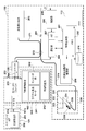
- FIG. 1 shows an external configuration of an image diagnostic apparatus 100 using optical interference in the embodiment.
- the diagnostic imaging apparatus 100 includes a probe 101, a motor driving unit 102, and an operation control device 103, and the motor driving unit 102 and the operation control device 103 are connected to a signal via a connector 105. They are connected by a cable 104 containing a wire or an optical fiber.
- the probe 101 is directly inserted into a blood vessel, and is movable in the longitudinal direction and accommodates a rotatable imaging core.
- an optical transmission / reception unit that continuously transmits (measurement light) transmitted from the diagnostic imaging apparatus 100 into the blood vessel and continuously receives reflected light from the blood vessel.
- a housed housing is provided. In the diagnostic imaging apparatus 100, the state inside the blood vessel is measured by using the imaging core.
- the motor drive unit 102 is detachably attached to the probe 101, and drives the built-in motor to define the axial movement of the imaging core inserted in the probe 101 in the blood vessel and the rotation operation with respect to the axis. ing. That is, the motor drive unit 102 has a function of moving the inside of the catheter in the axial direction while rotating the imaging core.
- the motor driving unit 102 functions as a signal relay device between the optical transmission / reception unit in the imaging core and the operation control device 103. That is, the motor drive unit 102 has a function of transmitting the measurement light from the operation control device 103 to the optical transmission / reception unit and transmitting reflected light from the living tissue detected by the optical transmission / reception unit to the operation control device 103.
- the operation control device 103 has a function for inputting various set values and a function for processing optical interference data obtained by the measurement and displaying various blood vessel images when performing the measurement.
- 111 is a main body control unit.
- the body control unit 111 generates interference light data by causing interference between reflected light from the imaging core and reference light obtained by separating light from the light source, and performs FFT on the interference light data.
- line data is generated from the rotation center position in the radial direction.
- a blood vessel cross-sectional image based on optical interference is generated from the line data through an interpolation process.
- Reference numeral 111-1 is a printer and a DVD recorder, which prints the processing results in the main body control unit 111 or stores them as data.
- Reference numeral 112 denotes an operation panel, and the user inputs various setting values and instructions via the operation panel 112.
- Reference numeral 113 denotes a monitor (for example, LCD) as a display device, which displays various cross-sectional images generated by the main body control unit 111.
- Reference numeral 114 denotes a mouse as a pointing device (coordinate input device).
- FIG. 2 is a block configuration diagram of the diagnostic imaging apparatus 100.
- the functional configuration of the wavelength sweep type OCT will be described with reference to FIG.
- reference numeral 201 denotes a signal processing unit that controls the entire diagnostic imaging apparatus, and is composed of several circuits including a microprocessor.
- Reference numeral 210 denotes a non-volatile storage device represented by a hard disk, which stores various programs and data files executed by the signal processing unit 201.
- Reference numeral 202 denotes a memory (RAM) provided in the signal processing unit 201.
- a wavelength swept light source 203 is a light source that repeatedly generates light having a wavelength that changes within a preset range along the time axis.
- the light output from the wavelength swept light source 203 is incident on one end of the first single mode fiber 271 and transmitted toward the distal end side.
- the first single mode fiber 271 is optically coupled to the fourth single mode fiber 275 at an intermediate optical fiber coupler 272.
- the light incident on the first single mode fiber 271 and emitted from the optical fiber coupler 272 toward the front end is guided to the second single mode fiber 273 via the connector 105.
- the other end of the second single mode fiber 273 is connected to the optical rotary joint 230 in the motor drive unit 102.
- the probe 101 has an adapter 101 a for connecting to the motor drive unit 102. Then, the probe 101 is stably held by the motor driving unit 102 by connecting the probe 101 to the motor driving unit 102 by the adapter 101a. Further, a third single mode fiber 274 is accommodated in the imaging core 251 that is rotatably accommodated in the probe 101, and an end portion of the third single mode fiber 274 is connected to the optical rotary joint 230. . As a result, the second single mode fiber 273 and the third single mode fiber 274 are optically coupled.
- an optical transmission / reception unit 250 composed of a mirror and a lens that emits light in a direction substantially perpendicular to the rotation axis (details are shown in 3 will be described using 3a).
- the light emitted from the wavelength swept light source 203 passes through the first single mode fiber 271, the second single mode fiber 273, and the third single mode fiber 274 to the end of the third single mode fiber 274.
- the light is transmitted to the optical transceiver 250 provided in the unit.
- the optical transmission / reception unit 250 emits this light in a direction perpendicular to the axis of the third single mode fiber 274 and receives the reflected light. Then, the reflected light received by the optical transmission / reception unit 250 is guided in reverse and returned to the operation control device 103.
- an optical path length adjustment mechanism 220 that finely adjusts the optical path length of the reference light is provided at the opposite end of the fourth single mode fiber 275 coupled to the optical fiber coupler 272.
- the optical path length adjusting mechanism 220 functions as an optical path length changing unit that changes the optical path length corresponding to the variation in length so that the variation in length of each probe 101 can be absorbed when the probe 101 is replaced.
- a collimating lens 225 located at the end of the fourth single mode fiber 275 is provided on a movable uniaxial stage 224 as indicated by an arrow 226 in the optical axis direction.
- the uniaxial stage 224 functions as an optical path length changing unit having a variable range of the optical path length that can absorb the variation in the optical path length of the probe 101. Further, the uniaxial stage 224 also has a function as an adjusting means for adjusting the offset. For example, even when the tip of the probe 101 is not in close contact with the surface of the living tissue, the optical path length can be minutely changed by the uniaxial stage so as to interfere with the reflected light from the surface position of the living tissue. Is possible.
- the optical path length is finely adjusted by the uniaxial stage 224, and the light reflected by the mirror 223 via the grating 221 and the lens 222 is again guided to the fourth single mode fiber 275, and the second optical fiber coupler 272 performs the second operation. Is mixed with the light obtained from the single mode fiber 273 side and received as interference light by the photodiode portion (PD) 204.
- PD photodiode portion
- the interference light received by the photodiode unit 204 in this way is photoelectrically converted, amplified by the amplifier 205, and then input to the demodulator 206.
- the demodulator 206 performs demodulation processing for extracting only the signal portion of the interfered light, and its output is input to the A / D converter 207 as an interference light signal.
- the A / D converter 207 samples the interference light signal for 2048 points at 90 MHz, for example, and generates one line of digital data (interference light data).
- the sampling frequency of 90 MHz is based on the assumption that about 90% of the wavelength sweep cycle (25 ⁇ sec) is extracted as 2048 digital data when the wavelength sweep repetition frequency is 40 kHz. There is no particular limitation.
- the line-by-line interference light data generated by the A / D converter 207 is input to the signal processing unit 201 and temporarily stored in the memory 202.
- interference light data is frequency-resolved by FFT (Fast Fourier Transform) to generate data in the depth direction (line data).
- FFT Fast Fourier Transform
- the signal processing unit 201 constructs an optical cross-sectional image at each position in the blood vessel from the line data, and outputs it to the monitor 113 at a predetermined frame rate in some cases.
- the signal processing unit 201 is further connected to an optical path length adjustment driving unit 209 and a communication unit 208.
- the signal processing unit 201 controls the position of the uniaxial stage 224 (optical path length control) via the optical path length adjustment driving unit 209.
- the communication unit 208 incorporates several drive circuits and communicates with the motor drive unit 102 under the control of the signal processing unit 201. Specifically, a drive signal is supplied to the radial scanning motor for rotating the third single mode fiber by the optical rotary joint in the motor driving unit 102, and the encoder unit 242 for detecting the rotational position of the radial motor. Reception of the signal from the signal line, and supply of a drive signal to the linear drive unit 243 for pulling the third single mode fiber 274 at a predetermined speed.
- the above processing in the signal processing unit 201 is also realized by a predetermined program being executed by a computer.
- the signal processing unit 201 drives the wavelength swept light source 203 to drive the radial scanning motor 241 and the linear driving unit 243 (hereinafter, the radial scanning motor 241 and the linear driving unit). (Light irradiation and light reception processing by driving 243 is called scanning).
- the wavelength swept light is supplied from the wavelength swept light source 203 to the optical transmission / reception unit 250 at the tip of the imaging core 251 through the path as described above.
- the imaging core 251 moves along the rotation axis while rotating by the drive control of the motor drive unit 102.
- the light transmitting / receiving unit 250 also emits light to the vascular lumen surface and receives reflected light while rotating and moving along the blood vessel axis.
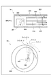
- the imaging core 251 includes a drive shaft 312 for accommodating the third single mode fiber 274 and transmitting the rotational force (arrow 302 in the figure) from the motor drive unit 102, and an optical transmission / reception unit 250 attached to the tip of the drive shaft 312. It is comprised with the housing 313 to accommodate.
- the one-dot chain line shown in the figure is the rotation center axis.
- the optical transmission / reception unit 250 moves in the catheter sheath 311.
- the optical transmission / reception unit 250 is composed of a hemispherical ball lens as shown in the figure.
- FIG. 3b of FIG. 3b is a diagram for explaining the reconstruction processing of the cross-sectional image of the lumen surface 351 of the blood vessel in which the optical transmission / reception unit 250 is located.
- the wavelength swept light source 203 generates light having a wavelength that varies along the time axis during a period in which the light transmitting / receiving unit 250 transmits and receives light once.
- the reflection intensity (or absorption amount) of light at each position in the radial direction from the rotational center position is obtained by performing FFT processing on one line of interference light data in the direction in which the light is irradiated by one transmission / reception of light.
- “Line data” is obtained. Accordingly, 512 line data extending radially from the rotation center 352 can be obtained by transmitting and receiving light 512 times, for example, during one rotation.
- the lens surface of the light transmitting / receiving unit 250 Although it is weak, reflection occurs on the lens surface of the light transmitting / receiving unit 250, the inner surface of the catheter sheath 311 and the boundary surfaces of the outer surface. That is, three circles appear in the vicinity of the rotation center position. Among these, the innermost circle 353 is caused by reflection on the lens surface of the optical transceiver 250.
- the basic configuration and functions of the diagnostic imaging apparatus 100 according to the embodiment have been described above. Next, detection of the ablation state by the diagnostic imaging apparatus 100 according to the embodiment will be described.
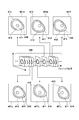
- FIG. 4 is a diagram schematically showing a group of cross-sectional images obtained by moving the imaging core 251 in the axial direction within the cauterized renal artery, and the axial position information (hereinafter referred to as pullback position) at that time.
- a plurality of cross-sectional images are arranged along the line.
- the linear drive unit 243 is configured by a pulse motor
- the pullback position is obtained by counting the drive pulses supplied to the pulse motor of the linear drive unit 243.
- the method of acquiring the pullback position is not limited to this, and for example, the pullback position may be acquired by providing a linear scale that moves in accordance with the position of the adapter and reading it with a sensor. As described above, a pullback position is added to each acquired cross-sectional image group.
- Each cross-sectional image constituting the cross-sectional image group 400 thus obtained includes a vascular tomographic image of the renal artery, and a vascular lumen wall and an external elastic plate can be observed from the vascular tomographic image.
- a vascular lumen wall and an external elastic plate can be observed from the vascular tomographic image.
- a continuous blood vessel lumen wall 412 and an outer elastic plate 411 are observed in the blood vessel tomographic image 410.
- the sympathetic nerve runs outside the outer elastic plate 411. Therefore, when the sympathetic nerve is cauterized through the lumen wall, the thermal energy is not only from the sympathetic nerve but also from the lumen wall and the sympathetic nerve. It is also applied to the outer elastic plate in between.
- the outer elastic plate to which heat energy is applied is denatured and cannot be observed on the cross-sectional image (specifically, the outer elastic plate to which heat energy is applied cannot be observed on the cross-sectional image due to degeneration. Decreases). Therefore, when the ablation position exists in the axial movement range (imaging range) of the imaging core 251, a part of the outer elastic plate 411 disappears in the vascular tomogram, and a cross-sectional image in which discontinuous portions exist is present. Will be acquired.
- disappearance occurs in the outer elastic plate 411 from the vascular tomographic image 410 of the cross-sectional image 401b. Thereafter, the discontinuous portion 413 occurs in the outer elastic plate 411 in the cross-sectional images 401c, 401d, and 401e acquired with the progress of the pullback position, and the discontinuous portion 413 in the outer elastic plate 411 disappears in the cross-sectional image 401f. ing. Therefore, in the example of FIG. 4, it can be seen that the outer elastic plate 411 has disappeared between the cross-sectional image 401b and the cross-sectional image 401e.
- the pullback position of the imaging core 251 is monitored, and the pullback position when each cross-sectional image is acquired can be determined. Therefore, the length of the blood vessel having the disappearing portion of the outer elastic plate can be determined from the difference between the pull-back positions of the cross-sectional image 401b where the disappearance of the outer elastic plate 411 starts and the cross-sectional image 401e where the disappearance of the outer elastic plate 411 ends.
- a range cautery range in which cauterization extends is estimated using this length and a model described below with reference to FIG. 5 to obtain the cautery depth.
- FIG. 5 is a diagram illustrating a model for estimating the ablation range.
- the length m of the disappearance portion is obtained from the difference between the pullback position 521 at the disappearance start and the pullback position 522 at the disappearance end.
- the difference between the pullback position of the cross-sectional image 401b and the pullback position of the cross-sectional image 401e is the length m of the disappearing portion.
- a semicircle 501 having a radius d and having a chord with a length m at the position t from the center is cauterized. Estimated range.
- the ablation catheter is estimated to be a semicircle centered on the inner surface of the blood vessel wall.
- the distance t from the lumen (inner wall surface) of the blood vessel to the outer elastic plate can be measured from the portion where the disappearance of the outer elastic plate has not occurred in the cross-sectional image.
- EEM External Elastic Membrane
- t the distance on the line between the position of the external elastic plate and the position of the blood vessel lumen wall determined using these methods.
- an average distance (may be age group or sex) of the outer elastic plate from the blood vessel lumen in the renal artery may be used.
- FIG. 6 is a diagram illustrating an example of a state in which the cross-sectional image 401d in the disappearance section illustrated in FIG.
- the cautery depth f at the pull-back position of the cross-sectional image 401d is calculated and displayed in the display area 601.
- a circumferential ablation range is detected based on a change in luminance value, and for example, a circumferential ablation range detected by an arrow 602 is clearly indicated.
- the ablation estimated range 603 may be displayed by connecting the point and both ends of the disappearance position and further extending to the lumen. Note that various methods such as linear and spline are conceivable for connecting the ends of the point and the disappearance position.
- a cross-sectional image for example, cross-sectional image 401a
- the display of the cauterization depth in the display area 601 and the cauterization range in the circumferential direction are displayed.
- the arrow 602 indicating is not displayed.
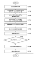
- FIG. 7 is a flowchart for explaining processing related to calculation and display of ablation depth among the processing executed by the microprocessor of the signal processing unit 201.
- step S701 the microprocessor acquires the cross-sectional image group 400 including a plurality of cross-sectional images at a plurality of pull-back positions as described in FIG. 4 by moving the imaging core 251 in the axial direction while performing radial scanning.
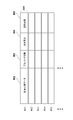
- FIG. 8 is a diagram illustrating a configuration example of data acquired in step S701. Each slice image of the slice image group 400 is stored in the memory 202 as frame data 801. At step S701, the cross-sectional image data 802 corresponding to each cross-sectional image and the pull-back position 803 at the time of acquisition of the cross-sectional image are recorded in the frame data 801.
- step S702 the microprocessor determines whether or not the outer elastic plate has disappeared for each of the cross-sectional image groups 400, and uses the determination result as an area of the disappearance occurrence 804 of each frame data (FIG. 8). ) The microprocessor detects the outer elastic plate for each cross-sectional image of the cross-sectional image group 400, and determines whether there is an interrupted portion (disappearance point) in the outer elastic plate.
- a position where the boundary where the luminance value first increases beyond a predetermined threshold appears is set as the position of the external elastic plate If the position of the external elastic plate specified using edge detection with Laplacian filter, Sobel filter, etc. is not within the specific depth range on the line, it is determined that the external elastic plate has disappeared.
- Each cross-sectional image may be displayed on the monitor 113, and the user may determine whether or not the outer elastic plate has disappeared by observing it. In this case, if the user designates “with disappearance” for each cross-sectional image in the disappearance section, the operation amount increases.
- the “exist” is automatically generated in the disappearance occurrence 804 of these cross-sectional images and all cross-sectional images (frame data) between them. May be written.
- the disappearance occurrence 804 of all the cross-sectional images 401b to 401e is set to “present”.
- step S703 the microprocessor refers to the disappearance occurrence 804 of the frame data 801 arranged in the order of the pull-back position (acquisition order), and the sectional image where the occurrence of the disappearance of the outer elastic plate has started and ended. Is identified. For example, at the portion where the frame data where the occurrence of erasure 804 is “Yes” continues, the first frame data is the start of erasure and the last frame data is the end of erasure. After that, in step S704, the microprocessor obtains the difference between the pullback position of the frame data where the disappearance of the outer elastic plate has started and the frame data where the outer elastic plate has ended, and determines the interval (disappearance interval) of the section where the outer elastic plate has partially disappeared. The distance, that is, the length m of the lost part is obtained. Since the pullback position is recorded in each frame data, the length m of the lost portion can be easily obtained by using this.
- step S705 the microprocessor calculates an ablation range for each cross-sectional image in the disappearance section using the model described in FIG. Then, the microprocessor calculates the ablation depth at the pullback position of each frame data (cross-sectional image) based on the ablation depth, and records it in the ablation depth 805 of the frame data. Note that the recording to the ablation depth 805 is performed on the frame data in which the disappearance occurrence 804 is “present”.
- step S707 when a cross-sectional image (frame data) to be displayed is selected, the microprocessor displays the cross-sectional image on the monitor 113. At this time, if the cross-sectional image to be displayed is a cross-sectional image of the disappearing section of the outer elastic plate, the process proceeds from step S709 to step S710, and the microprocessor determines the circumferential ablation range from the cross-sectional image. As shown in FIG. 6a, an ablation range 602 is displayed. In step S710, the microprocessor reads the ablation depth 805 of the frame data, and displays it in the display area 601 as “the ablation depth”.
- step S708 If the cross-sectional image to be displayed is not an image of the disappearance section, the process ends as it is from step S708, and the circumferential cautery range and irradiation zone depth are not displayed as described above, and 6b in FIG. You will get a display like
- the ablation catheter for cutting the sympathetic nerve and the probe 101 described above may be simultaneously inserted into the renal artery, and repeated OCT imaging may be performed during ablation with the ablation catheter to determine completion of ablation. .
- the microprocessor determines that the ablation has been completed and notifies the user to that effect.
- the disappearing section includes a frame where the disappearing portion has started to appear (cross-sectional image 401b in FIG. 4), and a frame immediately before the first frame in which the disappearing portion disappeared (cross-sectional image 401e in FIG. 4).
- the frame is between, but is not limited to this.
- the frame immediately before the frame where the disappearing portion starts to appear cross-sectional image 401a
- the first frame where the disappearing portion disappears cross-sectional image 401f
- the frame between them may be used as the disappearing section.
- a cautery catheter for cutting the sympathetic nerve is inserted to cauterize the lumen wall of the renal artery, and then The above-described cauterization depth may be calculated by inserting the probe 101 and performing OCT imaging.
- the cauterization depth of the renal artery sympathetic nerve can be determined more accurately by mapping the calculated cauterization depth to the position information of the nerve of the renal artery.
Abstract
An image processing device that processes a plurality of cross sectional images obtained with optical coherence tomography (OCT) by rotating an imaging core and moving same inside a catheter in the axial direction, wherein the image processing device: stores data pertaining to the cross sectional images by associating same to information about the position in the axial direction at the time each cross sectional image was obtained; extracts, from a plurality of cross sectional images, a first cross sectional image where a disappearing section in which a portion of an external elastic membrane contained in a vascular tomographic image is determined to disappear starts, and a second cross sectional image where the disappearing section ends; and obtains the stored information about the position in the axial direction for the first cross sectional image and the second cross sectional image and then calculates, on the basis of the difference in the information about the position in the axial direction, an ablation range, over which the ablation spans, in the location corresponding to the disappearing section.
Description
本発明は、光干渉断層像を処理する画像処理装置、画像処理方法、およびプログラムに関する。
The present invention relates to an image processing apparatus, an image processing method, and a program for processing an optical coherence tomographic image.
降圧剤を服用しても高血圧状態の改善が難しい難治性高血圧の患者に対しては、腎動脈周囲にある交感神経を切断し或いは損傷させ、その伝達を遮断することで血圧低下を期待できるという知見がある。
For patients with refractory hypertension who are unable to improve their hypertension even after taking antihypertensive agents, they can expect lower blood pressure by cutting or damaging the sympathetic nerves surrounding the renal arteries and blocking the transmission. There is knowledge.
経皮的に腎動脈の交感神経を切断する手技としては、焼灼用カテーテル(アブレーションデバイス)の先端部を腎動脈に導入して、腎動脈の内側から交感神経を焼灼することが提案されている。この種のアブレーションデバイスは、長尺状のシャフトの先端に電極部を有し、当該電極部を腎動脈の内壁に接触させ、腎動脈の周りにある交感神経に熱エネルギを印加し、交感神経を焼灼する(特許文献1)。
As a technique for percutaneously cutting the sympathetic nerve of the renal artery, it has been proposed to introduce the distal end of an ablation catheter (ablation device) into the renal artery and cauterize the sympathetic nerve from inside the renal artery. . This type of ablation device has an electrode part at the end of a long shaft, contacts the electrode part with the inner wall of the renal artery, applies heat energy to the sympathetic nerve around the renal artery, Cauterize (Patent Document 1).
交感神経は、腎動脈の周囲に存在することは知られているが、腎動脈の周辺組織中を不規則に走行しているため、腎動脈のどの部分が交感神経と接近しているのかは分からない。そこで、交感神経の切断の手技においては、腎動脈の内壁に沿った全周にわたって焼灼を実施することで、交感神経をより確実に切断することが行われる。但し、焼灼箇所では組織の変性や壊死が生じること、血管壁が腫脹することがあるので、同じ位置で内壁の全周にわたって焼灼するのではなく、血管軸方向へ移動しながら、すなわちスパイラル状に所定の間隔で熱エネルギを印加することが行われる。
Although sympathetic nerves are known to exist around the renal arteries, they run irregularly in the tissues surrounding the renal arteries, so which part of the renal arteries is close to the sympathetic nerves I do not understand. Therefore, in the sympathetic nerve cutting technique, the sympathetic nerve is more reliably cut by performing cauterization over the entire circumference along the inner wall of the renal artery. However, tissue degeneration and necrosis may occur at the ablation site, and the blood vessel wall may swell, so that it does not cauterize the entire circumference of the inner wall at the same position, but moves in the direction of the blood vessel axis, that is, spirally. Heat energy is applied at predetermined intervals.
また、近年では、腎動脈の交感神経を切断する手技を行う際、腎動脈の交感神経の位置を正確に把握するため、光干渉断層法の技術を用いることが提案されている。具体的には、光干渉断層法の技術を用いて、神経と筋肉又は神経組織と結合組織の間の複屈折境界を検出することで、腎動脈の神経の位置を判断する方法が提案されている(特許文献2)。
In recent years, it has been proposed to use an optical coherence tomography technique to accurately grasp the position of the sympathetic nerve in the renal artery when performing a procedure for cutting the sympathetic nerve in the renal artery. Specifically, a method for determining the nerve position of the renal artery by detecting the birefringent boundary between nerve and muscle or nerve tissue and connective tissue using the technique of optical coherence tomography has been proposed. (Patent Document 2).
一般に、上述のような腎動脈の内腔壁を介して交感神経を焼灼する手技では、各焼灼箇所について30秒~2分程度の所定時間をかけて熱エネルギを印加する。術者はこの間の、腎動脈内腔壁の温度、および電極と対極板間、或いは電極間のインピーダンスの変動を読み、経験則的に焼灼の成否を判断する。すなわち、交感神経の焼灼状態を直接的に判定する術は無かった。例えば、特許文献2では、腎動脈の交感神経を切断する手技を行う際、腎動脈の交感神経の位置を正確に把握できるが、腎動脈の内壁を熱エネルギで焼灼した後、その焼灼箇所の焼灼状態を判断することが難しかった。
Generally, in the procedure for cauterizing the sympathetic nerve through the lumen wall of the renal artery as described above, heat energy is applied to each cauterization site over a predetermined time of about 30 seconds to 2 minutes. During this period, the surgeon reads the temperature of the lumen wall of the renal artery and the impedance variation between the electrode and the counter electrode or between the electrodes, and empirically determines the success or failure of cauterization. That is, there was no way to directly determine the ablation state of the sympathetic nerve. For example, in Patent Document 2, when performing a procedure for cutting the sympathetic nerve of the renal artery, the position of the sympathetic nerve of the renal artery can be accurately grasped, but after cauterizing the inner wall of the renal artery with thermal energy, It was difficult to judge the state of shochu.
しかしながら、腎動脈の交感神経を切断する手技では、交感神経の焼灼が不足する場合には十分な治療効果が得られず、腎動脈内腔壁の焼灼が過剰な場合には合併症を誘発するリスクが高まってしまう虞がある。すなわち、腎動脈周辺の交感神経の焼灼の成否は、治療効果と直結している。そのため、腎動脈周辺の交感神経を切断する手技では、腎動脈周辺の交感神経の焼灼箇所の焼灼状態を判断することが求められている。
However, the procedure to cut the sympathetic nerve of the renal arteries does not provide a sufficient therapeutic effect if the sympathetic nerve is insufficient, and induces complications if the renal artery lumen wall is excessive. Risk may increase. That is, the success or failure of sympathetic nerve ablation around the renal artery is directly linked to the therapeutic effect. Therefore, in the technique of cutting the sympathetic nerve around the renal artery, it is required to determine the ablation state of the ablation site of the sympathetic nerve around the renal artery.
本発明は上記の課題に鑑みてなされたものであり、光干渉断層法により得られた断層像を用いてより正確に焼灼の状態を把握できるようにすることを目的とする。
The present invention has been made in view of the above problems, and an object thereof is to make it possible to more accurately grasp the state of cauterization using a tomographic image obtained by an optical coherence tomography.
上記の目的を達成するための本発明の位置態様による画像処理装置は以下の構成を備える。すなわち、
OCTにより、イメージングコアを回転させながらカテーテル内を軸方向に移動させて得られた複数の断面画像を処理する画像処理装置であって、
前記断面画像に関するデータを、それぞれの断面画像の取得時の前記軸方向の位置情報と対応づけて記憶する記憶手段と、
前記複数の断面画像において、血管断層像に含まれる外弾性板の一部が消失したと判断できる消失区間が開始する第1の断面画像と、該消失区間が終了する第2の断面画像を抽出する抽出手段と、
前記記憶手段より前記第1の断面画像と前記第2の断面画像の前記軸方向の位置情報を取得し、取得された前記軸方向の位置情報の差に基づいて、前記消失区間に対応する位置において焼灼が及んでいる焼灼範囲を算出する算出手段と、を備える。 In order to achieve the above object, an image processing apparatus according to a position aspect of the present invention comprises the following arrangement. That is,
An image processing apparatus that processes a plurality of cross-sectional images obtained by moving the inside of a catheter in an axial direction while rotating an imaging core by OCT,
Storage means for storing data relating to the cross-sectional image in association with positional information in the axial direction when each cross-sectional image is acquired;
In the plurality of cross-sectional images, a first cross-sectional image in which a disappearing section where it can be determined that a part of the outer elastic plate included in the vascular tomographic image has disappeared and a second cross-sectional image in which the disappearing section ends are extracted. Extraction means to
A position corresponding to the disappearance section is acquired from the storage means by acquiring position information in the axial direction between the first cross-sectional image and the second cross-sectional image, and based on the acquired difference in position information in the axial direction. And calculating means for calculating a shochu range where shochu is spreading.
本発明によれば、光干渉断層法により得られた断層像を用いることにより、より正確に焼灼の状態を把握できる。
According to the present invention, the state of cauterization can be grasped more accurately by using a tomographic image obtained by the optical coherence tomography.
本発明のその他の特徴及び利点は、添付図面を参照とした以下の説明により明らかになるであろう。なお、添付図面においては、同じ若しくは同様の構成には、同じ参照番号を付す。
Other features and advantages of the present invention will become apparent from the following description with reference to the accompanying drawings. In the accompanying drawings, the same or similar components are denoted by the same reference numerals.
添付図面は明細書に含まれ、その一部を構成し、本発明の実施の形態を示し、その記述と共に本発明の原理を説明するために用いられる。
実施形態にかかる画像診断装置の外観構成を示す図である。
実施形態における画像診断装置のブロック構成図である。
3aはプローブ先端の断面構成を示す図、3bは断面画像を生成する処理を示す図である。
画像診断装置により取得される断面画像群を説明する図である。
焼灼範囲を推定するモデルを説明する図である。
断面画像のモニタへの表示を説明する図である。
実施形態による焼灼範囲の推定処理を説明するフローチャートである。
フレームデータの構成例を示す図である。
The accompanying drawings are included in the specification, constitute a part thereof, show an embodiment of the present invention, and are used to explain the principle of the present invention together with the description.
It is a figure which shows the external appearance structure of the diagnostic imaging apparatus concerning embodiment. It is a block block diagram of the diagnostic imaging apparatus in embodiment. 3a is a diagram illustrating a cross-sectional configuration of the probe tip, and 3b is a diagram illustrating a process of generating a cross-sectional image. It is a figure explaining the cross-sectional image group acquired by an image diagnostic apparatus. It is a figure explaining the model which estimates the cautery range. It is a figure explaining the display to the monitor of a cross-sectional image. It is a flowchart explaining the estimation process of the cauterization range by embodiment. It is a figure which shows the structural example of frame data.
以下、本発明の各実施形態について添付図面を参照しながら詳細に説明する。なお、以下に述べる実施の形態は、本発明の好適な具体例であるから、技術的に好ましい種々の限定が付されているが、本発明の範囲は、以下の説明において特に本発明を限定する旨の記載がない限り、これらの態様に限られるものではない。
Hereinafter, embodiments of the present invention will be described in detail with reference to the accompanying drawings. The embodiment described below is a preferred specific example of the present invention, and thus various technically preferable limitations are given. However, the scope of the present invention is particularly limited in the following description. Unless otherwise stated, the present invention is not limited to these embodiments.
図1は、実施形態における光干渉を用いた画像診断装置100の外観構成を示している。
FIG. 1 shows an external configuration of an image diagnostic apparatus 100 using optical interference in the embodiment.
図1に示すように、画像診断装置100は、プローブ101と、モータ駆動部102と、操作制御装置103とを備え、モータ駆動部102と操作制御装置103とは、コネクタ105を介して、信号線や光ファイバを収容したケーブル104により接続されている。
As illustrated in FIG. 1, the diagnostic imaging apparatus 100 includes a probe 101, a motor driving unit 102, and an operation control device 103, and the motor driving unit 102 and the operation control device 103 are connected to a signal via a connector 105. They are connected by a cable 104 containing a wire or an optical fiber.
プローブ101は、直接血管内に挿入されるものであり、その長手方向に移動自在であって、且つ、回転自在なイメージングコアを収容している。このイメージングコアの先端には、画像診断装置100から伝送されてきた光を(測定光)を連続的に血管内に送信するとともに、血管内からの反射光を連続的に受信する光送受信部を収容したハウジングが設けられている。画像診断装置100では、該イメージングコアを用いることで血管内部の状態を測定する。
The probe 101 is directly inserted into a blood vessel, and is movable in the longitudinal direction and accommodates a rotatable imaging core. At the tip of the imaging core, there is an optical transmission / reception unit that continuously transmits (measurement light) transmitted from the diagnostic imaging apparatus 100 into the blood vessel and continuously receives reflected light from the blood vessel. A housed housing is provided. In the diagnostic imaging apparatus 100, the state inside the blood vessel is measured by using the imaging core.
モータ駆動部102は、プローブ101が着脱可能に取り付けられ、内蔵されたモータを駆動させることでプローブ101に内挿されたイメージングコアの血管内の軸方向の移動及びその軸に対する回転動作を規定している。すなわち、モータ駆動部102は、イメージングコアを回転させながらカテーテル内を軸方向に移動させる機能を有する。また、モータ駆動部102は、イメージングコア内の光送受信部と、操作制御装置103との間の信号の中継装置として機能する。すなわち、モータ駆動部102は、操作制御装置103からの測定光を光送受信部へ伝達すると共に、光送受信部で検出した生体組織からの反射光を操作制御装置103に伝達する機能を有する。
The motor drive unit 102 is detachably attached to the probe 101, and drives the built-in motor to define the axial movement of the imaging core inserted in the probe 101 in the blood vessel and the rotation operation with respect to the axis. ing. That is, the motor drive unit 102 has a function of moving the inside of the catheter in the axial direction while rotating the imaging core. The motor driving unit 102 functions as a signal relay device between the optical transmission / reception unit in the imaging core and the operation control device 103. That is, the motor drive unit 102 has a function of transmitting the measurement light from the operation control device 103 to the optical transmission / reception unit and transmitting reflected light from the living tissue detected by the optical transmission / reception unit to the operation control device 103.
操作制御装置103は、測定を行うにあたり、各種設定値を入力するための機能や、測定により得られた光干渉データを処理し、各種血管像を表示するための機能を備える。
The operation control device 103 has a function for inputting various set values and a function for processing optical interference data obtained by the measurement and displaying various blood vessel images when performing the measurement.
操作制御装置103において、111は本体制御部である。この本体制御部111は、イメージングコアからの反射光と、光源からの光を分離することで得られた参照光とを干渉させることで干渉光データを生成するとともに、該干渉光データをFFTすることで、回転中心位置から径方向に向かうラインデータを生成する。そして、ラインデータから補間処理を経て光干渉に基づく血管断面画像を生成する。
In the operation control device 103, 111 is a main body control unit. The body control unit 111 generates interference light data by causing interference between reflected light from the imaging core and reference light obtained by separating light from the light source, and performs FFT on the interference light data. As a result, line data is generated from the rotation center position in the radial direction. Then, a blood vessel cross-sectional image based on optical interference is generated from the line data through an interpolation process.
111-1はプリンタ及びDVDレコーダであり、本体制御部111における処理結果を印刷したり、データとして記憶したりする。112は操作パネルであり、ユーザは該操作パネル112を介して、各種設定値及び指示の入力を行う。113は表示装置としてのモニタ(たとえばLCD)であり、本体制御部111において生成された各種断面画像を表示する。114は、ポインティングデバイス(座標入力装置)としてのマウスである。
111-1 is a printer and a DVD recorder, which prints the processing results in the main body control unit 111 or stores them as data. Reference numeral 112 denotes an operation panel, and the user inputs various setting values and instructions via the operation panel 112. Reference numeral 113 denotes a monitor (for example, LCD) as a display device, which displays various cross-sectional images generated by the main body control unit 111. Reference numeral 114 denotes a mouse as a pointing device (coordinate input device).
次に、画像診断装置100の機能構成について説明する。図2は、画像診断装置100のブロック構成図である。以下、同図を用いて、波長掃引型OCTの機能構成について説明する。
Next, the functional configuration of the diagnostic imaging apparatus 100 will be described. FIG. 2 is a block configuration diagram of the diagnostic imaging apparatus 100. Hereinafter, the functional configuration of the wavelength sweep type OCT will be described with reference to FIG.
図中、201は画像診断装置の全体の制御を司る信号処理部であり、マイクロプロセッサをはじめ、いくつかの回路で構成される。210はハードディスクに代表される不揮発性の記憶装置であり、信号処理部201が実行する各種プログラムやデータファイルを格納している。202は信号処理部201内に設けられたメモリ(RAM)である。203は波長掃引光源であり、時間軸に沿って、予め設定された範囲内で変化する波長の光を繰り返し発生する光源である。
In the figure, reference numeral 201 denotes a signal processing unit that controls the entire diagnostic imaging apparatus, and is composed of several circuits including a microprocessor. Reference numeral 210 denotes a non-volatile storage device represented by a hard disk, which stores various programs and data files executed by the signal processing unit 201. Reference numeral 202 denotes a memory (RAM) provided in the signal processing unit 201. A wavelength swept light source 203 is a light source that repeatedly generates light having a wavelength that changes within a preset range along the time axis.
波長掃引光源203から出力された光は、第1のシングルモードファイバ271の一端に入射され、先端側に向けて伝送される。第1のシングルモードファイバ271は、途中の光ファイバカップラ272において第4のシングルモードファイバ275と光学的に結合されている。
The light output from the wavelength swept light source 203 is incident on one end of the first single mode fiber 271 and transmitted toward the distal end side. The first single mode fiber 271 is optically coupled to the fourth single mode fiber 275 at an intermediate optical fiber coupler 272.
第1のシングルモードファイバ271に入射され、光ファイバカップラ272より先端側に発した光は、コネクタ105を介して、第2のシングルモードファイバ273に導かれる。この第2のシングルモードファイバ273の他端はモータ駆動部102内の光ロータリージョイント230に接続されている。
The light incident on the first single mode fiber 271 and emitted from the optical fiber coupler 272 toward the front end is guided to the second single mode fiber 273 via the connector 105. The other end of the second single mode fiber 273 is connected to the optical rotary joint 230 in the motor drive unit 102.
一方、プローブ101はモータ駆動部102と接続するためのアダプタ101aを有する。そして、このアダプタ101aによりプローブ101をモータ駆動部102に接続することで、プローブ101が安定してモータ駆動部102に保持される。さらに、プローブ101内に回転自在に収容されたイメージングコア251には第3のシングルモードファイバ274が収容されおり、この第3のシングルモードファイバ274の端部が、光ロータリージョイント230に接続される。この結果、第2のシングルモードファイバ273と第3のシングルモードファイバ274が光学的に結合される。第3のシングルモードファイバ274の他方端(プローブ101の先頭部分側)には、光を回転軸に対してほぼ直行する方向に出射するミラーとレンズで構成される光送受信部250(詳細は図3の3aを用いて説明する)が設けられている。
On the other hand, the probe 101 has an adapter 101 a for connecting to the motor drive unit 102. Then, the probe 101 is stably held by the motor driving unit 102 by connecting the probe 101 to the motor driving unit 102 by the adapter 101a. Further, a third single mode fiber 274 is accommodated in the imaging core 251 that is rotatably accommodated in the probe 101, and an end portion of the third single mode fiber 274 is connected to the optical rotary joint 230. . As a result, the second single mode fiber 273 and the third single mode fiber 274 are optically coupled. At the other end of the third single-mode fiber 274 (the head portion side of the probe 101), an optical transmission / reception unit 250 composed of a mirror and a lens that emits light in a direction substantially perpendicular to the rotation axis (details are shown in 3 will be described using 3a).
上記の結果、波長掃引光源203が発した光は、第1のシングルモードファイバ271、第2のシングルモードファイバ273、第3のシングルモードファイバ274を介して、第3のシングルモードファイバ274の端部に設けられた光送受信部250に導かれる。光送受信部250は、この光を、第3のシングルモードファイバ274の軸に直行する方向に出射するとともに、その反射光を受信する。そして、光送受信部250で受信された反射光は、今度は逆に導かれ、操作制御装置103に返される。
As a result, the light emitted from the wavelength swept light source 203 passes through the first single mode fiber 271, the second single mode fiber 273, and the third single mode fiber 274 to the end of the third single mode fiber 274. The light is transmitted to the optical transceiver 250 provided in the unit. The optical transmission / reception unit 250 emits this light in a direction perpendicular to the axis of the third single mode fiber 274 and receives the reflected light. Then, the reflected light received by the optical transmission / reception unit 250 is guided in reverse and returned to the operation control device 103.
一方、光ファイバカップラ272に結合された第4のシングルモードファイバ275の反対の端部には、参照光の光路長を微調整する光路長調整機構220が設けられている。この光路長調整機構220は、プローブ101を交換した場合など、個々のプローブ101の長さのばらつきを吸収できるよう、その長さのばらつきに相当する光路長を変化させる光路長変更手段として機能する。そのため、第4のシングルモードファイバ275に端部に位置するコリメートレンズ225が、その光軸方向である矢印226で示すように移動自在な1軸ステージ224上に設けられている。
Meanwhile, an optical path length adjustment mechanism 220 that finely adjusts the optical path length of the reference light is provided at the opposite end of the fourth single mode fiber 275 coupled to the optical fiber coupler 272. The optical path length adjusting mechanism 220 functions as an optical path length changing unit that changes the optical path length corresponding to the variation in length so that the variation in length of each probe 101 can be absorbed when the probe 101 is replaced. . Therefore, a collimating lens 225 located at the end of the fourth single mode fiber 275 is provided on a movable uniaxial stage 224 as indicated by an arrow 226 in the optical axis direction.
具体的には、1軸ステージ224はプローブ101を交換した場合に、プローブ101の光路長のばらつきを吸収できるだけの光路長の可変範囲を有する光路長変更手段として機能する。さらに、1軸ステージ224はオフセットを調整する調整手段としての機能も備えている。例えば、プローブ101の先端が生体組織の表面に密着していない場合でも、1軸ステージにより光路長を微小変化させることにより、生体組織の表面位置からの反射光と干渉させる状態に設定することが可能である。
More specifically, when the probe 101 is replaced, the uniaxial stage 224 functions as an optical path length changing unit having a variable range of the optical path length that can absorb the variation in the optical path length of the probe 101. Further, the uniaxial stage 224 also has a function as an adjusting means for adjusting the offset. For example, even when the tip of the probe 101 is not in close contact with the surface of the living tissue, the optical path length can be minutely changed by the uniaxial stage so as to interfere with the reflected light from the surface position of the living tissue. Is possible.
1軸ステージ224で光路長が微調整され、グレーティング221、レンズ222を介してミラー223にて反射された光は再び第4のシングルモードファイバ275に導かれ、光ファイバカップラ272にて、第2のシングルモードファイバ273側から得られた光と混合されて、干渉光としてフォトダイオード部(PD)204にて受光される。
The optical path length is finely adjusted by the uniaxial stage 224, and the light reflected by the mirror 223 via the grating 221 and the lens 222 is again guided to the fourth single mode fiber 275, and the second optical fiber coupler 272 performs the second operation. Is mixed with the light obtained from the single mode fiber 273 side and received as interference light by the photodiode portion (PD) 204.
このようにしてフォトダイオード部204にて受光された干渉光は光電変換され、アンプ205により増幅された後、復調器206に入力される。この復調器206では干渉した光の信号部分のみを抽出する復調処理を行い、その出力は干渉光信号としてA/D変換器207に入力される。
The interference light received by the photodiode unit 204 in this way is photoelectrically converted, amplified by the amplifier 205, and then input to the demodulator 206. The demodulator 206 performs demodulation processing for extracting only the signal portion of the interfered light, and its output is input to the A / D converter 207 as an interference light signal.
A/D変換器207では、干渉光信号を例えば90MHzで2048ポイント分サンプリングして、1ラインのデジタルデータ(干渉光データ)を生成する。なお、サンプリング周波数を90MHzとしたのは、波長掃引の繰り返し周波数を40kHzにした場合に、波長掃引の周期(25μsec)の90%程度を2048点のデジタルデータとして抽出することを前提としたものであり、特にこれに限定されるものではない。
The A / D converter 207 samples the interference light signal for 2048 points at 90 MHz, for example, and generates one line of digital data (interference light data). The sampling frequency of 90 MHz is based on the assumption that about 90% of the wavelength sweep cycle (25 μsec) is extracted as 2048 digital data when the wavelength sweep repetition frequency is 40 kHz. There is no particular limitation.
A/D変換器207にて生成されたライン単位の干渉光データは、信号処理部201に入力され、一旦、メモリ202に格納される。そして、信号処理部201では干渉光データをFFT(高速フーリエ変換)により周波数分解して深さ方向のデータ(ラインデータ)を生成される。信号処理部201は、このラインデータから、血管内の各位置での光断面画像を構築し、場合によっては、所定のフレームレートでモニタ113に出力する。
The line-by-line interference light data generated by the A / D converter 207 is input to the signal processing unit 201 and temporarily stored in the memory 202. In the signal processing unit 201, interference light data is frequency-resolved by FFT (Fast Fourier Transform) to generate data in the depth direction (line data). The signal processing unit 201 constructs an optical cross-sectional image at each position in the blood vessel from the line data, and outputs it to the monitor 113 at a predetermined frame rate in some cases.
信号処理部201は、更に光路長調整用駆動部209、通信部208と接続されている。信号処理部201は光路長調整用駆動部209を介して1軸ステージ224の位置の制御(光路長制御)を行う。
The signal processing unit 201 is further connected to an optical path length adjustment driving unit 209 and a communication unit 208. The signal processing unit 201 controls the position of the uniaxial stage 224 (optical path length control) via the optical path length adjustment driving unit 209.
通信部208は、いくつかの駆動回路を内蔵するとともに、信号処理部201の制御下にてモータ駆動部102と通信する。具体的には、モータ駆動部102内の光ロータリージョイントによる第3のシングルモードファイバの回転を行うためのラジアル走査モータへの駆動信号の供給、ラジアルモータの回転位置を検出するためのエンコーダ部242からの信号受信、並びに、第3のシングルモードファイバ274を所定速度で引っ張るための直線駆動部243への駆動信号の供給である。
The communication unit 208 incorporates several drive circuits and communicates with the motor drive unit 102 under the control of the signal processing unit 201. Specifically, a drive signal is supplied to the radial scanning motor for rotating the third single mode fiber by the optical rotary joint in the motor driving unit 102, and the encoder unit 242 for detecting the rotational position of the radial motor. Reception of the signal from the signal line, and supply of a drive signal to the linear drive unit 243 for pulling the third single mode fiber 274 at a predetermined speed.
なお、信号処理部201における上記処理も、所定のプログラムがコンピュータによって実行されることで実現されるものとする。
Note that the above processing in the signal processing unit 201 is also realized by a predetermined program being executed by a computer.
上記構成において、プローブ101を患者の診断対象の血管位置(腎動脈など)に位置させると、ユーザの操作によりプローブ101の先端に向けて、ガイディングカテーテルなどを通じて透明なフラッシュ液を血管内に放出させる。血液の影響を除外するためである。そして、ユーザがスキャン開始の指示入力を行うと、信号処理部201は、波長掃引光源203を駆動し、ラジアル走査モータ241並びに直線駆動部243を駆動させる(以降、ラジアル走査モータ241と直線駆動部243の駆動による光の照射と受光処理をスキャニングと呼ぶ)。この結果、波長掃引光源203から波長掃引光が、上記のような経路でイメージングコア251の先端の光送受信部250に供給される。このとき、モータ駆動部102の駆動制御により、イメージングコア251は回転しながら、回転軸に沿って移動する。この結果、光送受信部250も、回転しながら、なおかつ、血管軸に沿って移動しながら、血管内腔面への光の出射とその反射光の受信を行うことになる。
In the above configuration, when the probe 101 is positioned at a blood vessel position (such as a renal artery) of a patient to be diagnosed, a transparent flush liquid is released into the blood vessel through a guiding catheter or the like toward the tip of the probe 101 by a user operation. Let This is to exclude the influence of blood. When the user inputs an instruction to start scanning, the signal processing unit 201 drives the wavelength swept light source 203 to drive the radial scanning motor 241 and the linear driving unit 243 (hereinafter, the radial scanning motor 241 and the linear driving unit). (Light irradiation and light reception processing by driving 243 is called scanning). As a result, the wavelength swept light is supplied from the wavelength swept light source 203 to the optical transmission / reception unit 250 at the tip of the imaging core 251 through the path as described above. At this time, the imaging core 251 moves along the rotation axis while rotating by the drive control of the motor drive unit 102. As a result, the light transmitting / receiving unit 250 also emits light to the vascular lumen surface and receives reflected light while rotating and moving along the blood vessel axis.
図3の3aは、プローブ101、並びに、それに収容されたイメージングコア251の先端部の断面図である。プローブ101の先端部は、光を透過するために透明なカテーテルシース311で構成される。イメージングコア251は、第3のシングルモードファイバ274を収容しモータ駆動部102からの回転力(図示の矢印302)を伝達するための駆動シャフト312と、その先端に取りつけられた光送受信部250を収容するハウジング313で構成される。図示の一点鎖線が回転中心軸である。また、モータ駆動部102が駆動シャフト312を図示の矢印303で示す方向に引っ張ることで、カテーテルシース311内を、光送受信部250が移動する。光送受信部250は、図示のように半球形状のボールレンズで構成される。この構造により、その傾斜面により、第3のシングルモードファイバ274から入射した光を、ほぼ直交する方向(図示の矢印301の方向)に反射する。この結果、血管組織に向けて光が照射され、その反射光が再びレンズを介して第3のシングルモードファイバ274に向けて転送されることになる。
3 is a cross-sectional view of the probe 101 and the tip of the imaging core 251 accommodated therein. The distal end portion of the probe 101 is composed of a transparent catheter sheath 311 for transmitting light. The imaging core 251 includes a drive shaft 312 for accommodating the third single mode fiber 274 and transmitting the rotational force (arrow 302 in the figure) from the motor drive unit 102, and an optical transmission / reception unit 250 attached to the tip of the drive shaft 312. It is comprised with the housing 313 to accommodate. The one-dot chain line shown in the figure is the rotation center axis. Further, when the motor drive unit 102 pulls the drive shaft 312 in the direction indicated by the arrow 303 in the drawing, the optical transmission / reception unit 250 moves in the catheter sheath 311. The optical transmission / reception unit 250 is composed of a hemispherical ball lens as shown in the figure. With this structure, the light incident from the third single mode fiber 274 is reflected by the inclined surface in a substantially orthogonal direction (the direction of the arrow 301 in the drawing). As a result, light is irradiated toward the vascular tissue, and the reflected light is transferred again toward the third single mode fiber 274 via the lens.
ここで、1枚の光断面画像の生成にかかる処理を図3の3bを用いて簡単に説明する。同図は光送受信部250が位置する血管の内腔面351の断面画像の再構成処理を説明するための図である。光送受信部250の1回転(2π=360度)する間に、複数回の測定光の送信と受信を行う。波長掃引光源203は、光送受信部250による1回の光の送受信を行う期間で、時間軸に変動する波長を持つ光を発生する。そのため、1回の光の送受信により、その光を照射した方向の1ラインの干渉光データをFFT処理することで、回転中心位置から径方向に向かう各位置における光の反射強度(もしくは吸収量)を示す「ラインデータ」が得られる。従って、1回転の間に、例えば512回の光の送受信を行うことで、回転中心352から放射線状に延びる512個のラインデータを得ることができる。
Here, a process for generating one optical cross-sectional image will be briefly described with reference to 3b of FIG. This figure is a diagram for explaining the reconstruction processing of the cross-sectional image of the lumen surface 351 of the blood vessel in which the optical transmission / reception unit 250 is located. During one rotation (2π = 360 degrees) of the optical transmission / reception unit 250, the measurement light is transmitted and received a plurality of times. The wavelength swept light source 203 generates light having a wavelength that varies along the time axis during a period in which the light transmitting / receiving unit 250 transmits and receives light once. Therefore, the reflection intensity (or absorption amount) of light at each position in the radial direction from the rotational center position is obtained by performing FFT processing on one line of interference light data in the direction in which the light is irradiated by one transmission / reception of light. “Line data” is obtained. Accordingly, 512 line data extending radially from the rotation center 352 can be obtained by transmitting and receiving light 512 times, for example, during one rotation.
これら512個のラインデータは、回転中心位置の近傍では密で、回転中心位置から離れるにつれて互いに疎になっていく。そこで、この各ラインの空いた空間における画素については、周知の補間処理を行なって生成していき、人間が視覚できる2次元の断面画像を生成することになる。また、生成された2次元断面画像を血管軸に沿って互いに接続することで、3次元血管画像を得ることもできる。なお、2次元の断面画像の中心位置は、光送受信部250の回転中心位置と一致するが、血管断面の中心位置ではない点に注意されたい。また、微弱であるが、光送受信部250のレンズ表面、カテーテルシース311の内面、及び、外面の各境界面で反射が起こる。つまり、回転中心位置の近傍には3つの円が現れる。このうち、一番内側の円353が、光送受信部250のレンズ表面での反射が起因するものである。
These 512 line data are dense in the vicinity of the rotation center position and become sparse with distance from the rotation center position. Therefore, the pixels in the empty space of each line are generated by performing a known interpolation process, and a two-dimensional cross-sectional image that can be seen by humans is generated. A three-dimensional blood vessel image can also be obtained by connecting the generated two-dimensional cross-sectional images to each other along the blood vessel axis. It should be noted that the center position of the two-dimensional cross-sectional image coincides with the rotation center position of the optical transmission / reception unit 250, but is not the center position of the blood vessel cross section. In addition, although it is weak, reflection occurs on the lens surface of the light transmitting / receiving unit 250, the inner surface of the catheter sheath 311 and the boundary surfaces of the outer surface. That is, three circles appear in the vicinity of the rotation center position. Among these, the innermost circle 353 is caused by reflection on the lens surface of the optical transceiver 250.
以上、実施形態における画像診断装置100の基本的な構成と機能について説明した。次に、実施形態の画像診断装置100による、焼灼状態の検出について説明する。
The basic configuration and functions of the diagnostic imaging apparatus 100 according to the embodiment have been described above. Next, detection of the ablation state by the diagnostic imaging apparatus 100 according to the embodiment will be described.
上述したように、イメージングコア251を回転させるとともに軸方向に移動しながら断面画像を得ることにより、血管の方向に沿って一連の複数の断面画像群が取得されることになる。以下、取得された断面画像群を用いて焼灼範囲、深度を算出する方法を説明する。なお、以下に説明する焼灼範囲、深度の算出やモニタへの表示処理は、画像診断装置100に内蔵または接続される画像処理装置により実現され得る。本実施形態では、画像診断装置100の信号処理部201に備わるマイクロプロセッサが所定のプログラムを実行することにより画像処理装置に係る機能が実現されるものとする。
As described above, by obtaining the cross-sectional image while rotating the imaging core 251 and moving in the axial direction, a series of a plurality of cross-sectional image groups are acquired along the direction of the blood vessel. Hereinafter, a method for calculating the ablation range and depth using the acquired cross-sectional image group will be described. Note that the calculation of the ablation range and depth described below and the display process on the monitor can be realized by an image processing apparatus built in or connected to the image diagnostic apparatus 100. In the present embodiment, it is assumed that a function related to the image processing apparatus is realized by a microprocessor included in the signal processing unit 201 of the image diagnostic apparatus 100 executing a predetermined program.
図4は、焼灼された腎動脈内でイメージングコア251を軸方向に移動することで得られた断面画像群を模式的に示す図であり、その際の軸方向の位置情報(以下、プルバック位置という)に沿って複数の断面画像が並んでいる。プルバック位置は、たとえば直線駆動部243がパルスモータで構成されている場合、直線駆動部243のパルスモータに供給された駆動パルスをカウントすることにより得られる。但し、プルバック位置の取得方法はこれに限られるものではなく、たとえば、アダプタの位置に応じて移動するリニアスケールを設け、これをセンサにより読み取ることで取得されてもよい。以上より、取得された断面画像群の各々にはプルバック位置が付加される。
FIG. 4 is a diagram schematically showing a group of cross-sectional images obtained by moving the imaging core 251 in the axial direction within the cauterized renal artery, and the axial position information (hereinafter referred to as pullback position) at that time. A plurality of cross-sectional images are arranged along the line. For example, when the linear drive unit 243 is configured by a pulse motor, the pullback position is obtained by counting the drive pulses supplied to the pulse motor of the linear drive unit 243. However, the method of acquiring the pullback position is not limited to this, and for example, the pullback position may be acquired by providing a linear scale that moves in accordance with the position of the adapter and reading it with a sensor. As described above, a pullback position is added to each acquired cross-sectional image group.
こうして得られた断面画像群400を構成する各々の断面画像は腎動脈の血管断層像を含み、血管断層像からは血管内腔壁と外弾性板が観察され得る。たとえば、断面画像401aでは、血管断層像410において連続した血管内腔壁412と外弾性板411が観察される。腎動脈では外弾性板411の外側に交感神経が走行しているため、内腔壁を介して交感神経の焼灼を実施した場合、熱エネルギは交感神経のみならず、内腔壁と交感神経の間にある外弾性板にも印加される。熱エネルギを印加された外弾性板は変性し、断面画像上で観察できなくなる(具体的には、熱エネルギを印加された外弾性板は、変性により、断面画像上で観察できなくなるほど輝度値が低下する)。したがって、イメージングコア251の軸方向への移動の範囲(撮影範囲)に焼灼位置が存在すると、血管断層像において外弾性板411の一部が消失し、不連続となる箇所の存在する断面画像が取得されることになる。
Each cross-sectional image constituting the cross-sectional image group 400 thus obtained includes a vascular tomographic image of the renal artery, and a vascular lumen wall and an external elastic plate can be observed from the vascular tomographic image. For example, in the cross-sectional image 401a, a continuous blood vessel lumen wall 412 and an outer elastic plate 411 are observed in the blood vessel tomographic image 410. In the renal artery, the sympathetic nerve runs outside the outer elastic plate 411. Therefore, when the sympathetic nerve is cauterized through the lumen wall, the thermal energy is not only from the sympathetic nerve but also from the lumen wall and the sympathetic nerve. It is also applied to the outer elastic plate in between. The outer elastic plate to which heat energy is applied is denatured and cannot be observed on the cross-sectional image (specifically, the outer elastic plate to which heat energy is applied cannot be observed on the cross-sectional image due to degeneration. Decreases). Therefore, when the ablation position exists in the axial movement range (imaging range) of the imaging core 251, a part of the outer elastic plate 411 disappears in the vascular tomogram, and a cross-sectional image in which discontinuous portions exist is present. Will be acquired.
図4の例では、断面画像401bの血管断層像410から、外弾性板411において消失(不連続部分413)が発生している。以降、プルバック位置の進行に伴って取得される断面画像401c、401d、401eにおいて外弾性板411に不連続部分413が発生しており、断面画像401fで外弾性板411における不連続部分413が無くなっている。したがって、図4の例では、断面画像401bから断面画像401eの間、外弾性板411に消失が発生していることがわかる。
In the example of FIG. 4, disappearance (discontinuous portion 413) occurs in the outer elastic plate 411 from the vascular tomographic image 410 of the cross-sectional image 401b. Thereafter, the discontinuous portion 413 occurs in the outer elastic plate 411 in the cross-sectional images 401c, 401d, and 401e acquired with the progress of the pullback position, and the discontinuous portion 413 in the outer elastic plate 411 disappears in the cross-sectional image 401f. ing. Therefore, in the example of FIG. 4, it can be seen that the outer elastic plate 411 has disappeared between the cross-sectional image 401b and the cross-sectional image 401e.
上述したように、イメージングコア251のプルバック位置は監視されており、各断面画像が取得された際のプルバック位置が判別可能となっている。したがって、外弾性板411の消失が開始した断面画像401bと外弾性板411の消失が終了した断面画像401eのプルバック位置の差から、外弾性板の消失部分を有する血管の長さが分かる。本実施形態では、この長さと、図5により以下に説明するモデルを用いて焼灼が及んでいる範囲(焼灼範囲)を推定し、焼灼深度を得る。
As described above, the pullback position of the imaging core 251 is monitored, and the pullback position when each cross-sectional image is acquired can be determined. Therefore, the length of the blood vessel having the disappearing portion of the outer elastic plate can be determined from the difference between the pull-back positions of the cross-sectional image 401b where the disappearance of the outer elastic plate 411 starts and the cross-sectional image 401e where the disappearance of the outer elastic plate 411 ends. In the present embodiment, a range (cautery range) in which cauterization extends is estimated using this length and a model described below with reference to FIG. 5 to obtain the cautery depth.
図5は焼灼範囲を推定するためのモデルを説明する図である。まず、消失開始のプルバック位置521と消失終了のプルバック位置522の差から消失部分の長さmを得る。図4の例では、断面画像401bのプルバック位置と断面画像401eのプルバック位置の差が消失部分の長さmとなる。そして、血管内腔(血管内腔壁412)から外弾性板411までの距離をtとした場合に、中心から距離tの位置に長さmの弦を持つ、半径dの半円501を焼灼範囲と推定する。なお、焼灼は、アブレーションカテーテルの電極が血管壁内面に接した状態で行われたとの仮定の元、血管壁内面上に中心がある半円を焼灼範囲と推定する。この場合、半径dは、
d=√(t2+(m/2)2)
により得られる。このような焼灼範囲のモデル化により、消失区間内の任意のプルバック位置における焼灼深度を算出することができる。たとえば、プルバック位置523における焼灼深度fは、プルバック位置521とプルバック位置523の差をbとした場合、
f=√(d2-(m/2-b)2)
により得られる。これにより、図4の断面画像401bから断面画像401eまでの各断面画像について焼灼深度を得ることができる。 FIG. 5 is a diagram illustrating a model for estimating the ablation range. First, the length m of the disappearance portion is obtained from the difference between thepullback position 521 at the disappearance start and the pullback position 522 at the disappearance end. In the example of FIG. 4, the difference between the pullback position of the cross-sectional image 401b and the pullback position of the cross-sectional image 401e is the length m of the disappearing portion. Then, assuming that the distance from the blood vessel lumen (blood vessel lumen wall 412) to the outer elastic plate 411 is t, a semicircle 501 having a radius d and having a chord with a length m at the position t from the center is cauterized. Estimated range. Note that, based on the assumption that the ablation catheter electrode is in contact with the inner surface of the blood vessel wall, the ablation catheter is estimated to be a semicircle centered on the inner surface of the blood vessel wall. In this case, the radius d is
d = √ (t 2 + (m / 2) 2 )
Is obtained. By modeling the ablation range, it is possible to calculate the ablation depth at an arbitrary pullback position in the disappearance section. For example, the cautery depth f at the pull backposition 523 is b when the difference between the pull back position 521 and the pull back position 523 is b.
f = √ (d 2 − (m / 2−b) 2 )
Is obtained. Thereby, the ablation depth can be obtained for each cross-sectional image from thecross-sectional image 401b to the cross-sectional image 401e in FIG.
d=√(t2+(m/2)2)
により得られる。このような焼灼範囲のモデル化により、消失区間内の任意のプルバック位置における焼灼深度を算出することができる。たとえば、プルバック位置523における焼灼深度fは、プルバック位置521とプルバック位置523の差をbとした場合、
f=√(d2-(m/2-b)2)
により得られる。これにより、図4の断面画像401bから断面画像401eまでの各断面画像について焼灼深度を得ることができる。 FIG. 5 is a diagram illustrating a model for estimating the ablation range. First, the length m of the disappearance portion is obtained from the difference between the
d = √ (t 2 + (m / 2) 2 )
Is obtained. By modeling the ablation range, it is possible to calculate the ablation depth at an arbitrary pullback position in the disappearance section. For example, the cautery depth f at the pull back
f = √ (d 2 − (m / 2−b) 2 )
Is obtained. Thereby, the ablation depth can be obtained for each cross-sectional image from the
なお、血管の内腔(内壁面)から外弾性板(EEM:External ElasticMembrane)までの距離tは、断面画像において外弾性板の消失が発生していない部分から計測することができる。例えば、1ラインの干渉光データを腎動脈内腔壁から外側に向けて読み込んだとき、最初に輝度値が予め定めた閾値を越えて増加する境界が現われる箇所を外弾性板の位置とする方法や、ラプラシアンフィルタ、ソーベルフィルタなどによってエッジ強調した上で外弾性板の位置を検出する方法など、色々な方法が考えられる。これらの方法を用いて判定した外弾性板の位置と血管内腔壁の位置の当該ライン上での距離をtとする。あるいは、腎動脈における血管内腔から外弾性板の平均的な距離(年齢層別、性別であってもい)を用いてもよい。
In addition, the distance t from the lumen (inner wall surface) of the blood vessel to the outer elastic plate (EEM: External Elastic Membrane) can be measured from the portion where the disappearance of the outer elastic plate has not occurred in the cross-sectional image. For example, when one line of interference light data is read outward from the renal artery lumen wall, a position where the boundary where the luminance value first increases beyond a predetermined threshold appears is set as the position of the external elastic plate Various methods such as a method of detecting the position of the outer elastic plate after edge enhancement by a Laplacian filter, a Sobel filter, or the like can be considered. Let t be the distance on the line between the position of the external elastic plate and the position of the blood vessel lumen wall determined using these methods. Alternatively, an average distance (may be age group or sex) of the outer elastic plate from the blood vessel lumen in the renal artery may be used.
図6の6aは、図5に示した消失区間にある断面画像401dがモニタ113に表示された状態の一例を示す図である。上述した方法により、断面画像401dのプルバック位置における焼灼深度fが算出され、表示エリア601に表示される。また、輝度値の変化に基づいて周方向の焼灼範囲が検出され、たとえば矢印602により検出された周方向の焼灼範囲が明示される。その他に、図6の6cに示すように、外弾性板の消失位置の両端を結ぶ線分の垂直二等分線上で、内腔から深さf(fは焼灼深度)の点をとり、その点と、消失位置の両端を結び、さらに内腔へ延ばすことで、焼灼推定範囲603を表示しても良い。なお、点と消失位置の両端の接続方法はリニア、スプラインなどいろいろな方法が考えられる。他方、図6の6bに示されるように、消失区間外の断面画像(たとえば断面画像401a)がモニタ113に表示された場合には、表示エリア601における焼灼深度の表示や、周方向の焼灼範囲を示す矢印602の表示は行われない。
6a in FIG. 6 is a diagram illustrating an example of a state in which the cross-sectional image 401d in the disappearance section illustrated in FIG. By the method described above, the cautery depth f at the pull-back position of the cross-sectional image 401d is calculated and displayed in the display area 601. Further, a circumferential ablation range is detected based on a change in luminance value, and for example, a circumferential ablation range detected by an arrow 602 is clearly indicated. In addition, as shown in 6c of FIG. 6, on the vertical bisector connecting the both ends of the disappearance position of the outer elastic plate, a point of depth f (f is the cauterization depth) is taken from the lumen, The ablation estimated range 603 may be displayed by connecting the point and both ends of the disappearance position and further extending to the lumen. Note that various methods such as linear and spline are conceivable for connecting the ends of the point and the disappearance position. On the other hand, as shown in 6b of FIG. 6, when a cross-sectional image (for example, cross-sectional image 401a) outside the disappearing section is displayed on the monitor 113, the display of the cauterization depth in the display area 601 and the cauterization range in the circumferential direction are displayed. The arrow 602 indicating is not displayed.
以上の処理について図7を参照してさらに説明する。図7は、信号処理部201のマイクロプロセッサにより実行される処理のうち、焼灼深度の算出と表示に関する処理を説明するフローチャートである。
The above processing will be further described with reference to FIG. FIG. 7 is a flowchart for explaining processing related to calculation and display of ablation depth among the processing executed by the microprocessor of the signal processing unit 201.
ステップS701において、マイクロプロセッサは、イメージングコア251をラジアル走査させながら軸方向に移動することにより、図4で説明したような、複数のプルバック位置の複数の断面画像からなる断面画像群400を取得する。図8は、ステップS701で取得されるデータの構成例を説明する図である。断面画像群400の各断面画像は、フレームデータ801としてメモリ202に格納される。ステップS701の時点では、フレームデータ801に、個々の断面画像に対応する断面画像データ802とその断面画像の取得時のプルバック位置803が記録される。
In step S701, the microprocessor acquires the cross-sectional image group 400 including a plurality of cross-sectional images at a plurality of pull-back positions as described in FIG. 4 by moving the imaging core 251 in the axial direction while performing radial scanning. . FIG. 8 is a diagram illustrating a configuration example of data acquired in step S701. Each slice image of the slice image group 400 is stored in the memory 202 as frame data 801. At step S701, the cross-sectional image data 802 corresponding to each cross-sectional image and the pull-back position 803 at the time of acquisition of the cross-sectional image are recorded in the frame data 801.
続いて、ステップS702において、マイクロプロセッサは、断面画像群400の各々について外弾性板の消失が発生しているか否かを判定し、その判定結果を各フレームデータの消失発生804のエリア(図8)に書き込む。マイクロプロセッサは断面画像群400の各断面画像について外弾性板を検出し、外弾性板に中断する箇所(消失個所)があるかどうかを判定する。例えば、1ラインの干渉光データを腎動脈内腔壁から外側に向けて読み込んだとき、最初に輝度値が予め定めた閾値を越えて増加する境界が現われる箇所を外弾性板の位置とする方法や、ラプラシアンフィルタ、ソーベルフィルタなどによってエッジ強調した上で検出する方法などを用いて特定した外弾性板の位置が当該ライン上の特定の深度範囲にない場合、外弾性板は消失したと判定する、など色々な方法が考えられる。なお、各断面画像をモニタ113に表示させて、ユーザがこれを観察することにより外弾性板の消失の有無を判定するようにしてもよい。この場合、消失区間中の各断面画像にユーザが「消失発生あり」を指定すると操作量が多くなってしまう。そこで、消失開始の断面画像と消失終了の断面画像をユーザが指定することにより、それら断面画像と、それらの間にある全ての断面画像(フレームデータ)の消失発生804に自動的に「あり」を書き込むようにしてもよい。たとえばユーザが断面画像401bを消失開始、断面画像401eを消失終了と判定すると、断面画像401b~401eまでの全ての断面画像の消失発生804が「あり」に設定される。
Subsequently, in step S702, the microprocessor determines whether or not the outer elastic plate has disappeared for each of the cross-sectional image groups 400, and uses the determination result as an area of the disappearance occurrence 804 of each frame data (FIG. 8). ) The microprocessor detects the outer elastic plate for each cross-sectional image of the cross-sectional image group 400, and determines whether there is an interrupted portion (disappearance point) in the outer elastic plate. For example, when one line of interference light data is read outward from the renal artery lumen wall, a position where the boundary where the luminance value first increases beyond a predetermined threshold appears is set as the position of the external elastic plate If the position of the external elastic plate specified using edge detection with Laplacian filter, Sobel filter, etc. is not within the specific depth range on the line, it is determined that the external elastic plate has disappeared. Various methods can be considered. Each cross-sectional image may be displayed on the monitor 113, and the user may determine whether or not the outer elastic plate has disappeared by observing it. In this case, if the user designates “with disappearance” for each cross-sectional image in the disappearance section, the operation amount increases. Therefore, when the user designates a cross-sectional image at the start of disappearance and a cross-sectional image at the end of disappearance, the “exist” is automatically generated in the disappearance occurrence 804 of these cross-sectional images and all cross-sectional images (frame data) between them. May be written. For example, when the user determines that the cross-sectional image 401b is disappearing start and the cross-sectional image 401e is disappearing end, the disappearance occurrence 804 of all the cross-sectional images 401b to 401e is set to “present”.
次に、ステップS703において、マイクロプロセッサは、プルバック位置の順(取得の順)に並ぶフレームデータ801の消失発生804を参照して外弾性板の消失の発生が開始した断面画像と終了した断面画像を特定する。たとえば、消失発生804が「あり」となっているフレームデータが連続している箇所の、先頭のフレームデータを消失の開始、末尾のフレームデータを消失の終了とする。その後、ステップS704において、マイクロプロセッサは、外弾性板の消失が開始したフレームデータと終了したフレームデータのプルバック位置の差を求め、外弾性板が部分的に消失している区間(消失区間)の距離、すなわち消失部分の長さmを取得する。プルバック位置は各フレームデータに記録されているので、これを用いることで消失部分の長さmは容易に求まる。
Next, in step S703, the microprocessor refers to the disappearance occurrence 804 of the frame data 801 arranged in the order of the pull-back position (acquisition order), and the sectional image where the occurrence of the disappearance of the outer elastic plate has started and ended. Is identified. For example, at the portion where the frame data where the occurrence of erasure 804 is “Yes” continues, the first frame data is the start of erasure and the last frame data is the end of erasure. After that, in step S704, the microprocessor obtains the difference between the pullback position of the frame data where the disappearance of the outer elastic plate has started and the frame data where the outer elastic plate has ended, and determines the interval (disappearance interval) of the section where the outer elastic plate has partially disappeared. The distance, that is, the length m of the lost part is obtained. Since the pullback position is recorded in each frame data, the length m of the lost portion can be easily obtained by using this.
次に、ステップS705において、マイクロプロセッサは、消失区間中の各断面画像について、図5で説明したモデルを用いて焼灼範囲を算出する。そして、マイクロプロセッサは、焼灼深度に基づいて各フレームデータ(断面画像)のプルバック位置における焼灼深度を算出し、フレームデータの焼灼深度805に記録する。なお、焼灼深度805への記録は、消失発生804が「あり」となっているフレームデータについてなされる。
Next, in step S705, the microprocessor calculates an ablation range for each cross-sectional image in the disappearance section using the model described in FIG. Then, the microprocessor calculates the ablation depth at the pullback position of each frame data (cross-sectional image) based on the ablation depth, and records it in the ablation depth 805 of the frame data. Note that the recording to the ablation depth 805 is performed on the frame data in which the disappearance occurrence 804 is “present”.
次に、マイクロプロセッサは、断面画像を表示するための表示制御を行う。まず、ステップS707において、表示対象の断面画像(フレームデータ)が選択されると、マイクロプロセッサは、その断面画像をモニタ113に表示する。このとき、表示対象の断面画像が外弾性板の消失区間の断面画像であった場合には、処理はステップS709からステップS710へ進み、マイクロプロセッサはその断面画像から周方向の焼灼範囲を判定し、図6の6aに示されるように焼灼範囲を矢印602を表示する。そして、ステップS710において、マイクロプロセッサはフレームデータの焼灼深度805を読み出し、「焼灼の深さ」として表示エリア601に表示する。なお、表示対象の断面画像が消失区間の画像でなければ、処理はステップS708からそのまま終了し、上述したような周方向の焼灼範囲や照射区の深さの表示は行われず、図6の6bのような表示を得ることになる。
Next, the microprocessor performs display control for displaying the cross-sectional image. First, in step S707, when a cross-sectional image (frame data) to be displayed is selected, the microprocessor displays the cross-sectional image on the monitor 113. At this time, if the cross-sectional image to be displayed is a cross-sectional image of the disappearing section of the outer elastic plate, the process proceeds from step S709 to step S710, and the microprocessor determines the circumferential ablation range from the cross-sectional image. As shown in FIG. 6a, an ablation range 602 is displayed. In step S710, the microprocessor reads the ablation depth 805 of the frame data, and displays it in the display area 601 as “the ablation depth”. If the cross-sectional image to be displayed is not an image of the disappearance section, the process ends as it is from step S708, and the circumferential cautery range and irradiation zone depth are not displayed as described above, and 6b in FIG. You will get a display like
なお、交感神経の切断のための焼灼用カテーテルと上述したプローブ101を同時に腎動脈に挿入し、焼灼用カテーテルによる焼灼中に繰り返しOCT撮影することにより、焼灼の完了を判定するようにしてもよい。その場合、マイクロプロセッサは、たとえば、上述した焼灼深度の最大値(図5のd)が所定値を超えた場合に焼灼が完了したと判定し、その旨をユーザに通知する。
The ablation catheter for cutting the sympathetic nerve and the probe 101 described above may be simultaneously inserted into the renal artery, and repeated OCT imaging may be performed during ablation with the ablation catheter to determine completion of ablation. . In that case, for example, when the maximum value of the ablation depth (d in FIG. 5) described above exceeds a predetermined value, the microprocessor determines that the ablation has been completed and notifies the user to that effect.
また、上記実施形態では、消失区間は、消失部分が出現し始めたフレーム(図4の断面画像401b)と、消失部分が無くなった最初のフレームの直前(図4の断面画像401e)と、これらの間のフレームとしているが、これに限られるものではない。たとえば、消失部分が出現し始めたフレームの直前のフレーム(断面画像401a)と消失部分が無くなった最初のフレーム(断面画像401f)、及びこれらの間のフレームを消失区間としてよい。
Further, in the above embodiment, the disappearing section includes a frame where the disappearing portion has started to appear (cross-sectional image 401b in FIG. 4), and a frame immediately before the first frame in which the disappearing portion disappeared (cross-sectional image 401e in FIG. 4). The frame is between, but is not limited to this. For example, the frame immediately before the frame where the disappearing portion starts to appear (cross-sectional image 401a), the first frame where the disappearing portion disappears (cross-sectional image 401f), and the frame between them may be used as the disappearing section.
また、光干渉断層法の技術を用いて腎動脈の神経の位置を検出した後、交感神経の切断のための焼灼用カテーテルを挿入して腎動脈の内腔壁の焼灼を行い、その後に上述したプローブ101を挿入してOCT撮影することにより、上述した焼灼深度を算出してもよい。これにより、腎動脈の神経の位置情報に算出した焼灼深度をマッピングすることで腎動脈の交感神経の焼灼状況をより正確に判断することができる。
In addition, after detecting the position of the nerve of the renal artery using the optical coherence tomography technique, a cautery catheter for cutting the sympathetic nerve is inserted to cauterize the lumen wall of the renal artery, and then The above-described cauterization depth may be calculated by inserting the probe 101 and performing OCT imaging. Thereby, the cauterization depth of the renal artery sympathetic nerve can be determined more accurately by mapping the calculated cauterization depth to the position information of the nerve of the renal artery.
本発明は上記実施の形態に制限されるものではなく、本発明の精神及び範囲から離脱することなく、様々な変更及び変形が可能である。従って、本発明の範囲を公にするために、以下の請求項を添付する。
The present invention is not limited to the above embodiment, and various changes and modifications can be made without departing from the spirit and scope of the present invention. Therefore, in order to make the scope of the present invention public, the following claims are attached.
本願は、2015年3月30日提出の日本国特許出願特願2015-068626を基礎として優先権を主張するものであり、その記載内容の全てを、ここに援用する。
This application claims priority on the basis of Japanese Patent Application No. 2015-068626 filed on Mar. 30, 2015, the entire contents of which are incorporated herein by reference.
Claims (10)
- OCTにより、イメージングコアを回転させながらカテーテル内を軸方向に移動させて得られた複数の断面画像を処理する画像処理装置であって、
前記断面画像に関するデータを、それぞれの断面画像の取得時の前記軸方向の位置情報と対応づけて記憶する記憶手段と、
前記複数の断面画像において、血管断層像に含まれる外弾性板の一部が消失したと判断できる消失区間が開始する第1の断面画像と、該消失区間が終了する第2の断面画像を抽出する抽出手段と、
前記記憶手段より前記第1の断面画像と前記第2の断面画像の前記軸方向の位置情報を取得し、取得された前記軸方向の位置情報の差に基づいて、前記消失区間に対応する位置において焼灼が及んでいる焼灼範囲を算出する算出手段と、を備えることを特徴とする画像処理装置。 An image processing apparatus that processes a plurality of cross-sectional images obtained by moving the inside of a catheter in an axial direction while rotating an imaging core by OCT,
Storage means for storing data relating to the cross-sectional image in association with positional information in the axial direction when each cross-sectional image is acquired;
In the plurality of cross-sectional images, a first cross-sectional image in which a disappearing section where it can be determined that a part of the outer elastic plate included in the vascular tomographic image has disappeared and a second cross-sectional image in which the disappearing section ends are extracted. Extraction means to
A position corresponding to the disappearance section is acquired from the storage means by acquiring position information in the axial direction between the first cross-sectional image and the second cross-sectional image, and based on the acquired difference in position information in the axial direction. An image processing apparatus comprising: calculating means for calculating an ablation range where the ablation is exerting. - 前記算出手段は、血管の内壁から外弾性板までの距離をt、前記軸方向の位置情報の差をmとした場合に、中心からの距離がtの位置に長さmの弦を有する半円を前記焼灼範囲とすることを特徴とする請求項1に記載の画像処理装置。 When the distance from the inner wall of the blood vessel to the outer elastic plate is t, and the difference in the positional information in the axial direction is m, the calculation means has a chord having a length m at a position where the distance from the center is t. The image processing apparatus according to claim 1, wherein a circle is the ablation range.
- 前記算出手段は、前記半円に基づいて前記消失区間におけるそれぞれの断面画像の焼灼の深さを算出することを特徴とする請求項2に記載の画像処理装置。 3. The image processing apparatus according to claim 2, wherein the calculating means calculates a cautery depth of each cross-sectional image in the disappearing section based on the semicircle.
- 前記抽出手段は、前記消失区間の開始の断面画像と前記消失区間の終了の断面画像の、ユーザによる指定を受け付けることを特徴とする請求項1乃至3のいずれか1項に記載の画像処理装置。 4. The image processing apparatus according to claim 1, wherein the extraction unit receives designation by a user of a cross-sectional image at the start of the disappearance section and a cross-sectional image at the end of the disappearance section. 5. .
- 前記抽出手段は、前記複数の断面画像のそれぞれについて血管断層像における外弾性板の像を検出し、それぞれの断面画像について外弾性板の部分的な消失の有無を判定することを特徴とする請求項1乃至3のいずれか1項に記載の画像処理装置。 The extraction means detects an image of an outer elastic plate in a vascular tomogram for each of the plurality of cross-sectional images, and determines whether or not the outer elastic plate is partially lost for each cross-sectional image. Item 4. The image processing device according to any one of Items 1 to 3.
- 前記消失区間に属する断面画像が表示手段への表示対象に選択された場合に、選択された断面画像とともに前記算出手段により算出された焼灼範囲から得られる焼灼の深さを表示する表示制御手段をさらに備えることを特徴とする請求項1乃至5のいずれか1項に記載の画像処理装置。 Display control means for displaying the ablation depth obtained from the ablation range calculated by the calculation means together with the selected cross-section image when a cross-sectional image belonging to the disappearance section is selected as a display target on the display means. The image processing apparatus according to claim 1, further comprising:
- 前記選択された断面画像の輝度値の変化に基づいて周方向の焼灼範囲を検出する検出手段をさらに備え、
前記表示制御手段は、前記選択された断面画像の表示において、前記検出手段により検出された前記周方向の焼灼範囲を明示することを特徴とする請求項6に記載の画像処理装置。 Detecting means for detecting a cautery range in the circumferential direction based on a change in luminance value of the selected cross-sectional image;
The image processing apparatus according to claim 6, wherein the display control unit clearly shows the circumferential cauterization range detected by the detection unit in displaying the selected cross-sectional image. - 前記抽出手段により抽出された焼灼の深さが所定値を超えた場合に焼灼が完了した旨を通知する通知手段をさらに備えることを特徴とする請求項1乃至7のいずれか1項に記載の画像処理装置。 The informing device according to any one of claims 1 to 7, further comprising notification means for notifying that shochu has been completed when the depth of the shochu extracted by the extracting means exceeds a predetermined value. Image processing device.
- OCTにより、イメージングコアを回転させながらカテーテル内を軸方向に移動させて得られた複数の断面画像を処理する画像処理方法であって、
前記断面画像に関するデータを、それぞれの断面画像の取得時の前記軸方向の位置情報と対応づけてメモリに記憶する記憶工程と、
前記複数の断面画像において、血管断層像に含まれる外弾性板の一部が消失したと判断できる消失区間が開始する第1の断面画像と、該消失区間が終了する第2の断面画像を抽出する抽出手段と、
前記メモリより前記第1の断面画像と前記第2の断面画像の前記軸方向の位置情報を取得し、取得された前記軸方向の位置情報の差に基づいて、前記消失区間に対応する位置において焼灼が及んでいる焼灼範囲を算出する算出工程と、を有することを特徴とする画像処理方法。 An image processing method for processing a plurality of cross-sectional images obtained by moving the inside of a catheter in an axial direction while rotating an imaging core by OCT,
A storage step of storing data relating to the cross-sectional image in a memory in association with the axial position information at the time of acquisition of each cross-sectional image;
In the plurality of cross-sectional images, a first cross-sectional image in which a disappearing section where it can be determined that a part of the outer elastic plate included in the vascular tomographic image has disappeared and a second cross-sectional image in which the disappearing section ends are extracted. Extraction means to
The position information in the axial direction between the first cross-sectional image and the second cross-sectional image is acquired from the memory, and the position corresponding to the disappearance section is based on the difference in the acquired position information in the axial direction. An image processing method comprising: a calculating step of calculating an ablation range where the ablation reaches. - 請求項9に記載された画像処理方法の各工程をコンピュータに実行させるためのプログラム。 A program for causing a computer to execute each step of the image processing method according to claim 9.
Priority Applications (4)
| Application Number | Priority Date | Filing Date | Title |
|---|---|---|---|
| EP16772474.9A EP3278713B1 (en) | 2015-03-30 | 2016-03-23 | Oct image processing device and method |
| CN201680019756.8A CN107427191B (en) | 2015-03-30 | 2016-03-23 | Image processing apparatus and method, program |
| JP2017509841A JP6674447B2 (en) | 2015-03-30 | 2016-03-23 | Image processing apparatus and method, program |
| US15/719,837 US10559077B2 (en) | 2015-03-30 | 2017-09-29 | Image processing apparatus, image processing method, and program |
Applications Claiming Priority (2)
| Application Number | Priority Date | Filing Date | Title |
|---|---|---|---|
| JP2015-068626 | 2015-03-30 | ||
| JP2015068626 | 2015-03-30 |
Related Child Applications (1)
| Application Number | Title | Priority Date | Filing Date |
|---|---|---|---|
| US15/719,837 Continuation US10559077B2 (en) | 2015-03-30 | 2017-09-29 | Image processing apparatus, image processing method, and program |
Publications (1)
| Publication Number | Publication Date |
|---|---|
| WO2016158593A1 true WO2016158593A1 (en) | 2016-10-06 |
Family
ID=57006766
Family Applications (1)
| Application Number | Title | Priority Date | Filing Date |
|---|---|---|---|
| PCT/JP2016/059088 WO2016158593A1 (en) | 2015-03-30 | 2016-03-23 | Image processing device and method, and program |
Country Status (5)
| Country | Link |
|---|---|
| US (1) | US10559077B2 (en) |
| EP (1) | EP3278713B1 (en) |
| JP (1) | JP6674447B2 (en) |
| CN (1) | CN107427191B (en) |
| WO (1) | WO2016158593A1 (en) |
Cited By (1)
| Publication number | Priority date | Publication date | Assignee | Title |
|---|---|---|---|---|
| WO2022070275A1 (en) * | 2020-09-29 | 2022-04-07 | オリンパス株式会社 | Support device, endoscopic system, support method, and program |
Families Citing this family (3)
| Publication number | Priority date | Publication date | Assignee | Title |
|---|---|---|---|---|
| JP6440136B1 (en) * | 2018-09-06 | 2018-12-19 | 株式会社Medi Plus | Medical video switcher |
| US20230108133A1 (en) * | 2021-10-01 | 2023-04-06 | Canon U.S.A., Inc. | Devices, systems, and methods for detecting external elastic lamina (eel) from intravascular oct images |
| CN116492049B (en) * | 2023-06-29 | 2023-10-03 | 北京智愈医疗科技有限公司 | Method and device for determining conformal ablation range of prostate |
Citations (5)
| Publication number | Priority date | Publication date | Assignee | Title |
|---|---|---|---|---|
| JP2008543511A (en) * | 2005-06-24 | 2008-12-04 | ヴォルケイノウ・コーポレーション | Vascular image preparation method |
| JP2010042182A (en) * | 2008-08-18 | 2010-02-25 | Fujifilm Corp | Laser treatment device |
| JP2012157384A (en) * | 2011-01-28 | 2012-08-23 | Fujifilm Corp | Diagnosis support apparatus, diagnosis support method, lesion detection apparatus, and lesion detection method |
| JP2012200532A (en) * | 2011-03-28 | 2012-10-22 | Terumo Corp | Imaging apparatus for diagnosis and display method |
| WO2014068606A1 (en) * | 2012-10-29 | 2014-05-08 | テルモ株式会社 | Vessel insertion type device |
Family Cites Families (14)
| Publication number | Priority date | Publication date | Assignee | Title |
|---|---|---|---|---|
| DE10355275B4 (en) * | 2003-11-26 | 2009-03-05 | Siemens Ag | catheter device |
| JP2010516304A (en) * | 2007-01-19 | 2010-05-20 | サニーブルック・ヘルス・サイエンシズ・センター | Imaging probe having imaging means combining ultrasound and optics |
| US20100168739A1 (en) * | 2008-12-31 | 2010-07-01 | Ardian, Inc. | Apparatus, systems, and methods for achieving intravascular, thermally-induced renal neuromodulation |
| US9089331B2 (en) * | 2009-07-31 | 2015-07-28 | Case Western Reserve University | Characterizing ablation lesions using optical coherence tomography (OCT) |
| EP2488250B1 (en) * | 2009-10-12 | 2015-11-25 | Kona Medical, Inc. | Energetic modulation of nerves |
| JP5508092B2 (en) * | 2010-03-30 | 2014-05-28 | テルモ株式会社 | Optical diagnostic imaging apparatus and display control method thereof |
| EP2443992A2 (en) * | 2010-10-25 | 2012-04-25 | Fujifilm Corporation | Diagnosis support apparatus, diagnosis support method, lesioned part detection apparatus, and lesioned part detection method |
| US20120191079A1 (en) * | 2011-01-20 | 2012-07-26 | Hansen Medical, Inc. | System and method for endoluminal and translumenal therapy |
| US8545409B2 (en) * | 2011-04-14 | 2013-10-01 | St. Jude Medical, Inc. | Arrangement and interface for RF ablation system with acoustic feedback |
| WO2013099797A1 (en) | 2011-12-27 | 2013-07-04 | 東洋紡株式会社 | Photosensitive print plate developing method and developing device |
| WO2014045327A1 (en) * | 2012-09-24 | 2014-03-27 | テルモ株式会社 | Image diagnosis apparatus, and image processing method |
| US9301795B2 (en) * | 2012-10-29 | 2016-04-05 | Ablative Solutions, Inc. | Transvascular catheter for extravascular delivery |
| CN105473089A (en) * | 2013-06-05 | 2016-04-06 | 麦特文申公司 | Modulation of targeted nerve fibers |
| CN104200465B (en) * | 2014-08-20 | 2017-08-25 | 沈阳东软医疗系统有限公司 | The dividing method and device of cardiac three-dimensional image |
-
2016
- 2016-03-23 JP JP2017509841A patent/JP6674447B2/en active Active
- 2016-03-23 WO PCT/JP2016/059088 patent/WO2016158593A1/en active Application Filing
- 2016-03-23 CN CN201680019756.8A patent/CN107427191B/en active Active
- 2016-03-23 EP EP16772474.9A patent/EP3278713B1/en active Active
-
2017
- 2017-09-29 US US15/719,837 patent/US10559077B2/en active Active
Patent Citations (5)
| Publication number | Priority date | Publication date | Assignee | Title |
|---|---|---|---|---|
| JP2008543511A (en) * | 2005-06-24 | 2008-12-04 | ヴォルケイノウ・コーポレーション | Vascular image preparation method |
| JP2010042182A (en) * | 2008-08-18 | 2010-02-25 | Fujifilm Corp | Laser treatment device |
| JP2012157384A (en) * | 2011-01-28 | 2012-08-23 | Fujifilm Corp | Diagnosis support apparatus, diagnosis support method, lesion detection apparatus, and lesion detection method |
| JP2012200532A (en) * | 2011-03-28 | 2012-10-22 | Terumo Corp | Imaging apparatus for diagnosis and display method |
| WO2014068606A1 (en) * | 2012-10-29 | 2014-05-08 | テルモ株式会社 | Vessel insertion type device |
Non-Patent Citations (2)
| Title |
|---|
| HIROSHI SUZUMURA ET AL.: "Role of Rotational Atherectomy for Calcific Coronary Lesions in Determining the Initial and Long Term Outcomes of Stenting Evaluated by IVUS", JAPANESE JOURNAL OF INTERVENTIONAL CARDIOLOGY, vol. 15, no. 1, 2000, pages 32 - 40, XP009506643, ISSN: 0914-8922 * |
| See also references of EP3278713A4 * |
Cited By (1)
| Publication number | Priority date | Publication date | Assignee | Title |
|---|---|---|---|---|
| WO2022070275A1 (en) * | 2020-09-29 | 2022-04-07 | オリンパス株式会社 | Support device, endoscopic system, support method, and program |
Also Published As
| Publication number | Publication date |
|---|---|
| JPWO2016158593A1 (en) | 2018-02-01 |
| JP6674447B2 (en) | 2020-04-01 |
| US20180025481A1 (en) | 2018-01-25 |
| CN107427191B (en) | 2019-09-13 |
| US10559077B2 (en) | 2020-02-11 |
| EP3278713A1 (en) | 2018-02-07 |
| EP3278713B1 (en) | 2020-01-01 |
| EP3278713A4 (en) | 2018-12-12 |
| CN107427191A (en) | 2017-12-01 |
Similar Documents
| Publication | Publication Date | Title |
|---|---|---|
| US20190083717A1 (en) | Devices and methods for forming vascular access | |
| JP4768494B2 (en) | Diagnostic imaging apparatus and processing method thereof | |
| JP5485760B2 (en) | Optical coherence tomographic image forming apparatus and control method thereof | |
| JP5592137B2 (en) | Optical diagnostic imaging apparatus and display control method thereof | |
| JP6533078B2 (en) | Image diagnostic apparatus, control method thereof, program and computer readable storage medium | |
| JP2018512961A (en) | Dual lumen diagnostic catheter | |
| US10559077B2 (en) | Image processing apparatus, image processing method, and program | |
| JP2016507272A (en) | Functional gain measurement technique and display | |
| WO2019046155A1 (en) | Fiber optic imaging probe having cladding mode pullback trigger, and control method therefor | |
| JP5689728B2 (en) | Optical coherence tomographic image forming apparatus and control method thereof | |
| WO2011039983A1 (en) | Diagnostic imaging apparatus and method for controlling same | |
| JP6095770B2 (en) | Diagnostic imaging apparatus, operating method thereof, program, and computer-readable storage medium | |
| JP6059334B2 (en) | Diagnostic imaging apparatus, information processing apparatus, operating method thereof, program, and computer-readable storage medium | |
| WO2015044983A1 (en) | Image diagnostic device and method for controlling same | |
| JPWO2010098014A1 (en) | Diagnostic imaging apparatus and control method thereof | |
| JP5628785B2 (en) | Diagnostic imaging equipment | |
| JP5508092B2 (en) | Optical diagnostic imaging apparatus and display control method thereof | |
| JP6669720B2 (en) | Image diagnostic apparatus, operating method thereof, program, and computer-readable storage medium | |
| JP6100911B2 (en) | Diagnostic imaging apparatus and operating method thereof | |
| JP6514562B2 (en) | Image processing apparatus and method, program | |
| JP6809905B2 (en) | Diagnostic imaging device, operating method and program of diagnostic imaging device | |
| WO2014162366A1 (en) | Image diagnostic device, method for controlling same, program, and computer-readable storage medium | |
| JP2017127533A (en) | Optical coherence tomography apparatus, control method for optical coherence tomography apparatus, and program | |
| JP6584806B2 (en) | Diagnostic imaging apparatus, control method therefor, program, and computer-readable storage medium | |
| JP2016182303A (en) | Image diagnostic apparatus, control method thereof, program, and computer readable storage medium |
Legal Events
| Date | Code | Title | Description |
|---|---|---|---|
| 121 | Ep: the epo has been informed by wipo that ep was designated in this application |
Ref document number: 16772474 Country of ref document: EP Kind code of ref document: A1 |
|
| REEP | Request for entry into the european phase |
Ref document number: 2016772474 Country of ref document: EP |
|
| ENP | Entry into the national phase |
Ref document number: 2017509841 Country of ref document: JP Kind code of ref document: A |
|
| NENP | Non-entry into the national phase |
Ref country code: DE |