WO2016152916A1 - Radio communication control method and radio communication system - Google Patents
Radio communication control method and radio communication system Download PDFInfo
- Publication number
- WO2016152916A1 WO2016152916A1 PCT/JP2016/059179 JP2016059179W WO2016152916A1 WO 2016152916 A1 WO2016152916 A1 WO 2016152916A1 JP 2016059179 W JP2016059179 W JP 2016059179W WO 2016152916 A1 WO2016152916 A1 WO 2016152916A1
- Authority
- WO
- WIPO (PCT)
- Prior art keywords
- received
- transmission
- reception
- beamforming
- matrix
- Prior art date
Links
- 238000004891 communication Methods 0.000 title claims description 48
- 238000000034 method Methods 0.000 title claims description 39
- 239000011159 matrix material Substances 0.000 claims abstract description 238
- 239000013598 vector Substances 0.000 claims abstract description 170
- 238000012545 processing Methods 0.000 claims abstract description 88
- 230000005540 biological transmission Effects 0.000 claims description 221
- 230000008859 change Effects 0.000 claims description 25
- 238000000926 separation method Methods 0.000 claims description 11
- 230000001902 propagating effect Effects 0.000 claims 6
- 238000004364 calculation method Methods 0.000 abstract description 9
- 230000003247 decreasing effect Effects 0.000 abstract 1
- 238000006243 chemical reaction Methods 0.000 description 23
- 238000004260 weight control Methods 0.000 description 22
- 238000012986 modification Methods 0.000 description 20
- 230000004048 modification Effects 0.000 description 20
- 230000008569 process Effects 0.000 description 18
- 230000007274 generation of a signal involved in cell-cell signaling Effects 0.000 description 11
- 238000010586 diagram Methods 0.000 description 10
- 238000005516 engineering process Methods 0.000 description 5
- 238000004458 analytical method Methods 0.000 description 4
- 238000004590 computer program Methods 0.000 description 4
- 230000000694 effects Effects 0.000 description 4
- 238000000354 decomposition reaction Methods 0.000 description 3
- 230000000644 propagated effect Effects 0.000 description 3
- 230000005855 radiation Effects 0.000 description 3
- 230000009467 reduction Effects 0.000 description 2
- 230000008054 signal transmission Effects 0.000 description 2
- 101100298888 Arabidopsis thaliana PAD2 gene Proteins 0.000 description 1
- 101100030928 Arabidopsis thaliana PAF1 gene Proteins 0.000 description 1
- 101100465385 Arabidopsis thaliana PAF2 gene Proteins 0.000 description 1
- 101100398338 Enterococcus faecalis (strain ATCC 700802 / V583) prs2 gene Proteins 0.000 description 1
- 101100510342 Listeria ivanovii prs gene Proteins 0.000 description 1
- 101100137870 Saccharomyces cerevisiae (strain ATCC 204508 / S288c) PRE10 gene Proteins 0.000 description 1
- 230000009471 action Effects 0.000 description 1
- 230000006978 adaptation Effects 0.000 description 1
- 238000007796 conventional method Methods 0.000 description 1
- 230000002349 favourable effect Effects 0.000 description 1
- 238000003780 insertion Methods 0.000 description 1
- 230000037431 insertion Effects 0.000 description 1
- 238000004519 manufacturing process Methods 0.000 description 1
- 101150077839 pac1 gene Proteins 0.000 description 1
- 101150086435 prs1 gene Proteins 0.000 description 1
Images


Classifications
-
- H—ELECTRICITY
- H04—ELECTRIC COMMUNICATION TECHNIQUE
- H04B—TRANSMISSION
- H04B7/00—Radio transmission systems, i.e. using radiation field
- H04B7/02—Diversity systems; Multi-antenna system, i.e. transmission or reception using multiple antennas
- H04B7/04—Diversity systems; Multi-antenna system, i.e. transmission or reception using multiple antennas using two or more spaced independent antennas
- H04B7/06—Diversity systems; Multi-antenna system, i.e. transmission or reception using multiple antennas using two or more spaced independent antennas at the transmitting station
- H04B7/0686—Hybrid systems, i.e. switching and simultaneous transmission
- H04B7/0695—Hybrid systems, i.e. switching and simultaneous transmission using beam selection
-
- H—ELECTRICITY
- H04—ELECTRIC COMMUNICATION TECHNIQUE
- H04B—TRANSMISSION
- H04B7/00—Radio transmission systems, i.e. using radiation field
- H04B7/02—Diversity systems; Multi-antenna system, i.e. transmission or reception using multiple antennas
- H04B7/04—Diversity systems; Multi-antenna system, i.e. transmission or reception using multiple antennas using two or more spaced independent antennas
- H04B7/06—Diversity systems; Multi-antenna system, i.e. transmission or reception using multiple antennas using two or more spaced independent antennas at the transmitting station
- H04B7/0613—Diversity systems; Multi-antenna system, i.e. transmission or reception using multiple antennas using two or more spaced independent antennas at the transmitting station using simultaneous transmission
- H04B7/0615—Diversity systems; Multi-antenna system, i.e. transmission or reception using multiple antennas using two or more spaced independent antennas at the transmitting station using simultaneous transmission of weighted versions of same signal
- H04B7/0617—Diversity systems; Multi-antenna system, i.e. transmission or reception using multiple antennas using two or more spaced independent antennas at the transmitting station using simultaneous transmission of weighted versions of same signal for beam forming
-
- H—ELECTRICITY
- H04—ELECTRIC COMMUNICATION TECHNIQUE
- H04B—TRANSMISSION
- H04B7/00—Radio transmission systems, i.e. using radiation field
- H04B7/02—Diversity systems; Multi-antenna system, i.e. transmission or reception using multiple antennas
- H04B7/04—Diversity systems; Multi-antenna system, i.e. transmission or reception using multiple antennas using two or more spaced independent antennas
- H04B7/08—Diversity systems; Multi-antenna system, i.e. transmission or reception using multiple antennas using two or more spaced independent antennas at the receiving station
- H04B7/0868—Hybrid systems, i.e. switching and combining
- H04B7/088—Hybrid systems, i.e. switching and combining using beam selection
-
- H—ELECTRICITY
- H04—ELECTRIC COMMUNICATION TECHNIQUE
- H04B—TRANSMISSION
- H04B7/00—Radio transmission systems, i.e. using radiation field
- H04B7/02—Diversity systems; Multi-antenna system, i.e. transmission or reception using multiple antennas
- H04B7/10—Polarisation diversity; Directional diversity
-
- H—ELECTRICITY
- H04—ELECTRIC COMMUNICATION TECHNIQUE
- H04W—WIRELESS COMMUNICATION NETWORKS
- H04W16/00—Network planning, e.g. coverage or traffic planning tools; Network deployment, e.g. resource partitioning or cells structures
- H04W16/24—Cell structures
- H04W16/28—Cell structures using beam steering
-
- H—ELECTRICITY
- H04—ELECTRIC COMMUNICATION TECHNIQUE
- H04W—WIRELESS COMMUNICATION NETWORKS
- H04W88/00—Devices specially adapted for wireless communication networks, e.g. terminals, base stations or access point devices
- H04W88/02—Terminal devices
Definitions
- the present invention relates to a wireless communication control method and a wireless communication system.
- MIMO Multiple-Input and
- Multiple-Output Multiple-Output
- Massive-MIMO realizes advanced beam forming (Beam-Forming, BF) using a large amount of antenna elements as compared with conventional MIMO.
- Beam forming is a technique for controlling the directivity and shape of a beam (a transmission beam corresponding to a transmission antenna and a reception beam corresponding to a reception antenna) by controlling a plurality of antenna elements.
- the phase and amplitude of each antenna element can be controlled. Therefore, the greater the number of antenna elements used, the greater the degree of freedom of beam control.
- the beam forming applied to the transmission signal is mathematically expressed as a multiplication of a beam forming weight matrix (hereinafter sometimes referred to as a BF weight matrix) for a vector indicating the transmission signal.
- the BF weight matrix is expressed as a matrix including a plurality of beamforming weight vectors (hereinafter sometimes referred to as BF weight vectors) as components.
- BF weight vectors beamforming weight vectors
- the BF weight matrix and the BF weight vector may be collectively referred to as “BF weight”.
- fixed beam forming As an example of beam forming, fixed beam forming is exemplified.
- a beam forming weight (fixed beam) to be used is selected from a plurality of beam forming weight candidates prepared in advance.
- fixed beamforming beamforming for controlling a fixed beam and coding (precoding on the transmission side and postcoding on the reception side) for realizing compensation for multiplexing among multiple streams are separately performed.
- BF weight In order to properly execute MIMO transmission, it is considered important to appropriately execute beamforming, that is, to determine a suitable BF weight. In order to determine the BF weight, a large amount of calculation processing, for example, channel estimation is performed using all of the candidate BF weights, and an optimum BF weight is determined by comparing the channel estimation results. It is envisaged to choose.
- the Massive-MIMO transmission system employs a large number of antenna elements, and thus the above problem of increased processing load becomes more prominent.
- an object of the present invention is to determine a suitable BF weight while reducing the amount of calculation and to realize appropriate MIMO transmission.
- the radio communication control method of the present invention includes a precoding unit that performs precoding using a precoding matrix, and a phase corresponding to a transmission BF (beamforming) weight matrix with respect to the signal after the precoding is performed. And a transmission beamforming unit that performs transmission beamforming for imparting a change in amplitude, and a transmitter including NT transmission antennas that transmit the signal subjected to the transmission beamforming, and a space transmitted from the transmitter. and N R receive antennas for receiving the transmitted signal and to a plurality of the signal which the receiving antenna receives and performs receive beamforming to impart a change in the phase and amplitude corresponding to the received BF weight matrix received A beam forming unit and after the analog reception beam forming No.
- a wireless communication control method in a radio communication system comprising a receiver and a post coding unit that performs post coded with post-coding matrix, received by the N R receive antennas present
- the LR received beamforming circuits included in the received beamforming unit perform the received beamforming (N R / L R ) times on the received signal vector, thereby obtaining NR received BF output components.
- generating a receive BF output vector having, select and to calculate a received power for each of the N R of the reception BF output component, a L R number of the receiving BF output components to the received power descending order, selecting suitable receiving BF c containing L R-number of reception quadrature BF weight vector corresponding to the received BF output components which are It comprises determining a site matrix.
- Another radio communication control method of the present invention includes a precoding unit that performs precoding using a precoding matrix, and a phase and amplitude corresponding to a transmission BF weight matrix with respect to the signal after the precoding is performed.
- a transmitter including a transmission beamforming unit that performs transmission beamforming that imparts a change in frequency, and N T transmit antennas that transmit the signal subjected to the transmission beamforming, and is transmitted from the transmitter and propagates in space. and N R receive antennas present to receive the signal, received beamforming for a plurality of the signal which the receiving antenna receives and performs receive beamforming to impart a change in the phase and amplitude corresponding to the received BF weight matrix And the signal after the analog receive beamforming is performed.
- a radio communication control method in a radio communication system comprising a receiver and a post coding unit that performs post coded with coding matrix, on the received signal vector received by the N R receive antennas present,
- the LR received beamforming circuits included in the received beamforming unit perform received beamforming (N R / L R ) times to generate a received BF output vector having NR received BF output components.
- Another radio communication control method of the present invention includes a precoding unit that performs precoding using a precoding matrix, and a phase and amplitude corresponding to a transmission BF weight matrix with respect to the signal after the precoding is performed.
- a transmitter including a transmission beamforming unit that performs transmission beamforming that imparts a change in frequency, and N T transmit antennas that transmit the signal subjected to the transmission beamforming, and is transmitted from the transmitter and propagates in space. and N R receive antennas present to receive the signal, received beamforming for a plurality of the signal which the receiving antenna receives and performs receive beamforming to impart a change in the phase and amplitude corresponding to the received BF weight matrix And the signal after the analog receive beamforming is performed.
- a radio communication control method in a radio communication system comprising a receiver and a post coding unit that performs post coded with coding matrix, on the received signal vector received by the N R receive antennas present,
- Each of the LR receive beamforming circuits included in the receive beamforming unit performs a bypass reception operation for selecting and acquiring one of the elements of the received signal vector (N R / L R ) times.
- the wireless communication system of the present invention includes a precoding unit that performs precoding using a precoding matrix, a phase corresponding to a transmission BF (beamforming) weight matrix, and a signal after the precoding and
- a transmitter including a transmission beamforming unit that performs transmission beamforming that gives a change in amplitude, and NT transmission antennas that transmit signals subjected to the transmission beamforming; and a space transmitted from the transmitter.
- N R receive antennas present for receiving the propagated signal, for a plurality of the signal which the receiving antenna receives and performs receive beamforming to impart a change in the phase and amplitude corresponding to the received BF weight matrix received beam
- the forming unit and after the analog reception beam forming is performed Respect No., a receiver and a post coding unit that performs post coded with post-coding matrix, the receiving beam forming unit, the received signal vector received by the N R receive antennas present
- the LR received beamforming circuits included in the received beamforming unit execute received beamforming (N R / L R ) times, thereby receiving BF output having NR received BF output components.
- Another wireless communication system of the present invention includes a precoding unit that performs precoding using a precoding matrix, and a phase and amplitude corresponding to a transmission BF weight matrix with respect to the signal that has been subjected to the precoding.
- a transmitter including a transmission beamforming unit for applying transmission beamforming for imparting a change, and NT transmission antennas for transmitting the signals subjected to the transmission beamforming; and transmitted from the transmitter and propagated in space.
- N R receive antennas present receiving signals, to the plurality of signal the receiving antenna receives and performs receive beamforming to impart a change in the phase and amplitude corresponding to the received BF weight matrix receiving beam forming unit And the post-analog receive beamforming signal.
- a receiver and a post coding unit that performs post coded with coding matrix, the receiving beam forming unit with respect to the received signal vector received by the N R receive antennas present, the receive beamforming LR received beamforming circuits included in the unit perform received beamforming (N R / L R ) times to generate a received BF output vector having NR received BF output components, receiver to the received BF output vector is multiplied by the N R number of separation operator corresponding to the N R receive antennas present respectively, it obtains the received signal vector, the received signal vector To estimate a channel matrix, and using the estimated channel matrix, a plurality of receiving BF ways Calculated received power for each of the candidate Tobekutoru, selects a candidate for L R-number of the received BF weight vector to the received power is high order, suitable receiving comprising a candidate of the selected L R number of the receiving BF weight vector An arithmetic processing unit for determining a BF weight matrix is further provided.
- Another wireless communication system of the present invention includes a precoding unit that performs precoding using a precoding matrix, and a phase and amplitude corresponding to a transmission BF weight matrix with respect to the signal that has been subjected to the precoding.
- a transmitter including a transmission beamforming unit for applying transmission beamforming for imparting a change, and NT transmission antennas for transmitting the signals subjected to the transmission beamforming; and transmitted from the transmitter and propagated in space.
- N R receive antennas present receiving signals, to the plurality of signal the receiving antenna receives and performs receive beamforming to impart a change in the phase and amplitude corresponding to the received BF weight matrix receiving beam forming unit And the post-analog receive beamforming signal.
- each L R number of receive beamforming circuitry the reception beam forming unit comprises a reception at the N R receive antennas present
- the received signal vector is obtained by performing (N R / L R ) bypass reception operations for selecting and obtaining one of the received signal vector elements for the received signal vector,
- the receiver estimates a channel matrix using the received signal vector, calculates received power for each of a plurality of received BF weight vector candidates using the estimated channel matrix, and determines L in descending order of received power. selects a candidate of the R of the received BF weight vector, L R number of the receiving BF Weitobeku selected Further comprising a processing unit for determining a suitable receiving BF weight matrix including Le candidate.
- the weight matrix is determined in stages. Therefore, the number of combinations to be calculated is suppressed as compared with a configuration in which all combinations of weight matrices are determined by trial. As a result, a suitable BF weight matrix is determined while reducing the amount of computation required for determining the weight matrix.
- FIG. 3 is a schematic explanatory diagram of a Massive-MIMO transmission scheme according to the first embodiment.
- 1 is a schematic configuration diagram of a radio communication system according to a first embodiment. It is a figure which shows the functional structure of Massive-MIMO transmission which concerns on 1st Embodiment. It is a figure which shows the example of the circuit structure of the transmitter which concerns on 1st Embodiment. It is a figure which shows the example of the circuit structure of the receiver which concerns on 1st Embodiment. It is an outline figure of BF weight determination concerning a 1st embodiment. It is a functional block diagram of the small base station of 1st Embodiment. It is a functional block diagram of the user apparatus of a 1st embodiment.
- First Embodiment 1 Massive-MIMO transmission A Massive-MIMO transmission scheme according to the first embodiment of the present invention will be described.
- the Massive-MIMO transmission scheme in which the base station performs wireless communication using a large number of transmission antennas AT , a high wireless communication speed (data rate) by multiplexing is realized.
- data rate data rate
- the degree of freedom of antenna control when performing beam forming increases, higher beam forming than before is realized. Therefore, reduction of interference amount and effective use of radio resources are realized.
- the number of transmission antennas AT included in the base station adapted for Massive-MIMO is not limited to the following, but is 32 or more, 64 or more, 96 or more, 100 or more, 128 or more, It is preferable that the number is 192 or more, 200 or more, 256 or more, 500 or more, 512 or more, 1000 or more, or 1024 or more.
- a high frequency band for example, a frequency band of 10 GHz or higher
- the antenna since the size of the antenna element is proportional to the wavelength of the signal, the antenna can be further miniaturized when using a high frequency band in which the wavelength of the radio signal is relatively short.
- the higher the frequency the greater the propagation loss. Therefore, even if a radio signal is transmitted from the base station with the same transmission power, the high frequency band is used compared to the low frequency band. As a result, the received signal strength at the mobile station is reduced.
- FIG. 1 is a diagram schematically showing a reach range of a beam (radio signal) according to a frequency. Since a conventional base station (macro base station MeNB) performs radio communication using a low frequency band, the beam reaches farther even if a beam with a wide radiation pattern is used. On the other hand, since the base station (small base station MMNB) corresponding to the Massive-MIMO transmission system of this embodiment performs radio communication using a high frequency band, when using a beam with a wide radiation pattern, the macro base station Compared with MeNB, the distance which a beam reaches is short. However, when the beam radiation pattern width is narrowed by beam forming, even a small base station MMNB using a high frequency band can reach the beam far.
- FIG. 2 is a schematic configuration diagram of the wireless communication system 1 according to the first embodiment.
- the radio communication system 1 includes a macro base station MeNB, a small base station MMNB, a central control station MME, and a user apparatus UE.
- the small base station MMNB is a base station that supports the Massive-MIMO transmission scheme.
- the macro base station MeNB forms a macro cell Cm around it, and the small base station MMNB forms a Massive-MIMO cell (MM cell) Cmm around it.
- the frequency band (for example, 10 GHz band) used by the small base station MMNB has a higher frequency and propagation loss than the frequency band (for example, 2 GHz band) used by the macro base station MeNB, so the cell size of the MM cell Cmm is It is smaller than the cell size of the macro cell Cm. Therefore, there is a high possibility that the small base station MMNB and the user apparatus UE are connected by a line-of-sight.
- the MM cell Cmm can overlap with a wireless communicable area using other wireless access technology (Radio Access Technology, RAT) such as the macro cell Cm.
- RAT Radio Access Technology
- simultaneous connection Multiple Connectivity
- a public or local wireless LAN is exemplified.
- the propagation loss is compensated by the gain realized by beam forming.
- a plurality of data streams are spatially multiplexed and transmitted.
- a precoder and a transmit beamformer of a transmitter perform precoding and transmit beamforming, respectively
- a receiver eg, user It is preferred that the receiving beamformer and postcoder of the apparatus UE) perform the receiving beamforming and postcoding, respectively.
- L T rows and M columns
- N T is the number of transmitted beams
- Reception beam forming process to the receiving antenna
- a signal received at R L R rows N R column (L R receive beam number) received BF weight matrix of Is a process of multiplying by.
- a post-coding matrix of M rows and LR columns is applied to a signal subjected to reception beamforming. Is a process of multiplying by.
- the signal vector of M rows and 1 column after post-coding Is expressed by the following equation. In addition, it is another term added in the above mathematical formula (1). Is a noise vector of M rows and 1 column.
- FIG. 4 shows an equivalent circuit on the transmitter side
- FIG. 5 shows an equivalent circuit on the receiver side.
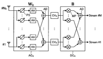
- the analog having relative frequency reception signal received by N R receive antennas A R, a plurality of variable phase shifters PS, the amplitude adjuster AA and the adder AD changes in phase and amplitude is imparted by the signal processing circuit AC R (i.e., analogically reception beam forming is performed).
- the signal processing circuit AC R i.e., analogically reception beam forming is performed.
- down-conversion, AD conversion, and Fourier transform are performed on the signal after reception beam forming by the processing circuit PC R
- digital post-coding matrix operation
- M streams are generated (reproduced).
- the analog signal processing circuit AC (AC T , AC R ) realizes one of a plurality of beam candidates (BF weight candidates) by the variable phase shifter PS and the amplitude adjuster AA as described above.
- a plurality of processing circuits corresponding to beam candidates may be provided, and one of the processing circuits may be selected by a control switch.
- the above configuration is particularly suitable for the Massive-MIMO transmission scheme in which the number of transmission antennas NT is sufficiently larger than the number of streams to be transmitted M (that is, M ⁇ NT ).
- M the number of transmission antennas
- N T the number of transmission antennas
- L T rows and M columns of a precoding matrix are used.
- N T rows L T columns transmit BF weight matrix M stream components are converted into NT transmit antenna components by the matrix operation according to.
- an optimum combination of weight matrices is determined by performing trials for all combinations of candidate weight matrices selected one by one for a plurality of weight matrices.
- the number of streams is M
- the precoding matrix Number of candidates is N P
- the transmission BF weighting matrix (transmitted beam pattern) The number of candidates is NWT
- the reception BF weight matrix (reception beam pattern) The number of candidates is N WR and the post-coding matrix
- N B N P ⁇ (N WT ) M ⁇ (N WR ) M ⁇ N B operations are required.
- the Massive-MIMO transmission scheme has a larger number of candidate beam patterns because the number of antennas is larger than that of the conventional MIMO transmission scheme. Therefore, when the above combination determination method is adopted, there is a problem that the amount of calculation increases in a geometric series and the processing load increases.
- the channel matrix Since it cannot be observed, it is necessary to actually transmit and receive radio signals and measure transmission characteristics.
- a suitable transmission BF weight matrix is first used. And preferred receive BF weight matrix And a preferred precoding matrix using the determined BF weight matrix or more. And the preferred postcoding matrix (Hereinafter, a transmission BF weight matrix, a reception BF weight matrix, a precoding matrix, and a postcoding matrix may be collectively referred to as a “weight matrix”). As described above, it is possible to reduce the amount of calculation by deciding a suitable weight matrix step by step and reducing the number of combinations to be calculated.
- the transmission BF weight is determined first, and then the reception BF weight is determined.
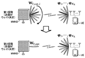
- FIG. 6 is a schematic diagram of BF weight determination according to the present embodiment.
- a transmission BF weight with the highest received power at the user apparatus UE is selected from the attempted transmission BF weights by switching transmission BF weight (transmission beam) candidates in the small base station MMNB.
- the user apparatus UE performs a reception operation by generating a plurality of orthogonal beams (reception orthogonal BF weights).
- received power is measured for each of a plurality of orthogonal beams (received orthogonal BF weights) in the user apparatus UE, and a predetermined number of received BF weights that realize higher received power are selected.
- the small base station MMNB performs transmission beamforming based on the preferred transmission BF weight selected in the first stage.
- FIG. 7 is a functional block diagram illustrating main components of the small base station MMNB (transmitter) of the first embodiment.
- the small base station MMNB includes a data signal generation unit 10, a reference signal generation unit 20, a baseband processing unit 30, a DA conversion unit 40, an RF processing unit 50, a feedback unit 60, a precoding control unit 70, and a transmission BF weight control unit 80. And a storage unit 90.
- the baseband processing unit 30 includes a precoding unit 32, and the RF processing unit 50 includes an up-conversion unit 52 and a transmission beam forming unit 54.
- N T transmit antennas A T are connected to the transmit beamforming unit 54.
- the data signal generation unit 10 generates a data signal to be included in the transmission signal for the user apparatus UE.
- the data signal generation unit 10 can generate a data signal as a plurality of streams. In the present embodiment, it is assumed that the data signal generation unit 10 generates data signals of M (M is an integer of 2 or more) streams.
- the reference signal generation unit 20 generates a reference signal to be included in the transmission signal for the user apparatus UE.
- the reference signal is, for example, a signal used for channel estimation in the user apparatus UE, initial synchronization between the user apparatus UE and the small base station MMNB, and identification of the small base station MMNB in the user apparatus UE.
- the reference signal generation unit 20 can also generate a plurality of series (M streams) of reference signals.
- the generated data signal and reference signal are input to the baseband processing unit 30 as a baseband signal.
- the baseband processing unit 30 is an element that processes an input baseband signal (data signal, reference signal).
- the baseband processing unit 30 performs precoding matrix on the M streams. Is provided with a precoding unit 32 that performs digital precoding (matrix operation).
- a signal combining a data signal and a reference signal is precoded by the precoding unit 32 and output from the baseband processing unit 30.
- a reference signal that is not precoded is output from the baseband processing unit 30.
- the DA conversion unit 40 converts the digital signal output from the baseband processing unit 30 into an analog signal and outputs the analog signal to the RF processing unit 50.
- the RF processing unit 50 is an element that processes an input analog signal and transmits it from the transmission antenna AT .
- the RF processing unit 50 includes an up-conversion unit 52 that converts an input analog signal to a radio frequency RF signal, and a transmission BF weight matrix for the frequency-converted signal.
- a transmission beam forming unit 54 for performing analog transmission beam forming based on the above. High-frequency signal output from the transmission beam forming unit 54 is transmitted from the transmitting antenna A T of the N T.
- the above-described analog transmission beamforming is a process of applying changes in phase and amplitude corresponding to multiplication of the transmission BF weight matrix to M analog signals using the variable phase shifter PS and the amplitude adjuster AA.
- the phase and amplitude between the plurality of transmission antennas AT correspond to multiplication of the transmission BF weight matrix. It changes in analog.
- the feedback unit 60 is an element that performs control-related communication with the user apparatus UE, and particularly supplies feedback information from the user apparatus UE to the precoding control unit 70 and the transmission BF weight control unit 80.
- the precoding control unit 70 controls the precoding matrix used in the precoding unit 32.
- the transmission BF weight control unit 80 controls the BF weight used in the transmission beam forming unit 54.
- the storage unit 90 stores information (for example, precoding matrix, transmission BF weight matrix) regarding control of wireless communication.
- elements that execute digital processing are a functional block realized by a CPU (Central Processing Unit) (not shown) executing a computer program stored in the storage unit 90 and functioning according to the computer program.
- CPU Central Processing Unit
- FIG. 8 is a functional block diagram illustrating main components of the user apparatus UE (receiver) according to the first embodiment.
- the user apparatus UE includes an RF processing unit 110, an AD conversion unit 120, a baseband processing unit 130, a signal analysis unit 140, an arithmetic processing unit 150, a reception BF weight control unit 160, a post coding control unit 170, a feedback unit 180, and a storage unit.
- the RF processing unit 110 includes a reception beamforming unit 112 and a down-conversion unit 114
- the baseband processing unit 130 includes a post-coding unit 132.
- N R reception antennas A R are connected to the reception beam forming unit 112.
- RF processing unit 110 is an element for processing a signal in which a plurality of receiving antennas A R has received.
- the RF processing unit 110 receives the received BF weight matrix with respect to the received signal.
- the reception beam forming unit 112 that performs analog reception beam forming based on the above, and the down conversion unit 114 that converts the frequency of the input signal into a baseband signal and outputs the baseband signal.
- the receiving beam forming unit 112 is provided with L R number of receive beamforming circuit RBC.
- N R receive antennas AR are branched and connected to each of the receive beamforming circuits RBC. Therefore, radio signals received by the receiving antenna A R of the N R present is inputted to each of the receiving beam forming circuit RBC, reception beam forming is performed.
- One receive beamforming circuit RBC is a receive BF weight matrix. 1 component (one received BF weight vector).
- analog reception beamforming is a change in the corresponding phase and amplitude multiplication of the received BF weight matrix, is a process to be applied to an analog signal N R present with variable phase shifter PS and an amplitude adjuster AA.
- analog reception beam forming more than in the analog reception beam forming, so that the phase and amplitude between the plurality of receiving antennas A R (between the signals received by a plurality of receiving antennas A R) corresponds to a multiplication of the received BF weight matrix Changes to analog.
- the AD conversion unit 120 converts the analog signal output from the RF processing unit 110 into a digital signal and outputs the digital signal to the baseband processing unit 130.
- the baseband processing unit 130 is an element that processes an input baseband signal and restores M streams.
- the baseband processing unit 130 applies a post-coding matrix to the signal output from the AD conversion unit 120. Is provided with a post coding unit 132 that performs digital post coding (matrix operation). M streams are reproduced by the above post-coding. The reproduced M streams are input to the signal analysis unit 140 and analyzed.
- the arithmetic processing unit 150 performs arithmetic processing such as reception power calculation and transmission / reception characteristic estimation on the digital signal output from the AD conversion unit 120.
- the reception BF weight control unit 160 controls the BF weight used in the reception beamforming unit 112.
- the post coding control unit 170 controls the post coding matrix used in the post coding unit 132.
- the feedback unit 180 is an element that performs communication related to control with the small base station MMNB, and in particular, transmits feedback information from the arithmetic processing unit 150 and the reception BF weight control unit 160 to the small base station MMNB.
- the storage unit 190 stores information related to wireless communication control (for example, a post-coding matrix and a reception BF weight matrix).
- elements that perform digital processing for example, a baseband processing unit 130, a signal analysis unit 140, an arithmetic processing unit 150, a reception BF weight control unit 160, a post coding control unit 170,
- the feedback unit 180 is a functional block realized by a CPU (not shown) executing a computer program stored in the storage unit 190 and functioning according to the computer program.
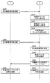
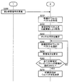
- FIG. 10 and FIG. 11 are operation flows showing the weight matrix determination of this embodiment. Schematically, according to the weight matrix determination of the present embodiment, the first stage (determination of preferred transmission BF weight vectors, steps S100 to S160) and the second stage (determination of preferred reception BF weight vectors, steps S200 to S230). ) Is executed as a result of the transmission BF weight matrix that is favorable (ie, optimal in the attempted range). And received BF weight matrix Is determined.
- the transmission BF weight control unit 80 of the small base station MMNB determines the candidate transmission BF weight vector from a plurality of (X) transmission BF weight vector candidates stored in the storage unit 90. Is selected (S100).
- the transmission BF weight control unit 80 has NT row and M column candidate transmission BF weight matrix including the selected candidate transmission BF weight vector.
- the reference signal that is, analog transmission beam forming is applied to the reference signal
- the transmission beam forming unit 54 is controlled so that transmission is performed from N T transmission antennas AT. (S110).
- transmission beamforming is performed on a reference signal that has not been precoded and transmitted.
- the reference signal to be transmitted after transmission beamforming is performed in step S110 May be referred to as a first reference signal RS1.
- Received signal vector of N R rows and one column corresponding to the N R the first reference signal RS1 received by the receiving antenna A R of Are branched and input to LR receive beamforming circuits RBC included in the receive beamforming unit 112, respectively.
- the user equipment receives BF weight controller 160 of the UE is to perform a receive beamforming in a time division to the received signal vector, and controls the reception beam forming unit 112 (L R number of receive beamforming circuit RBC).
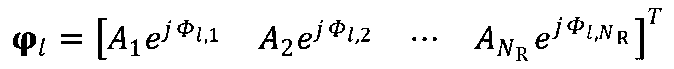
- Indicates the amount of amplitude adjustment Indicates the amount of phase rotation. That is, the nth component
- the received signal components corresponding to the n-th receive antenna A R of receive antennas A R of the N R present Amplitude adjustment amount and phase rotation amount with respect to.
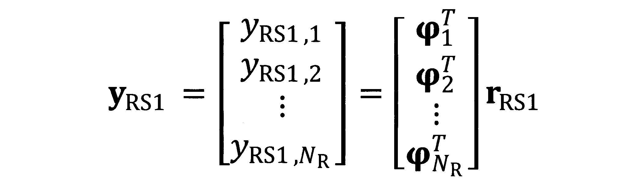
- L R number of receive beamforming circuit RBC based on the control of the reception BF weight control section 160, by executing in a time division a more receive beam forming operations for a (N R / L R) times, N R rows 1-column received BF output vector Is generated (S120). That, L R number of receive beamforming circuit RBC is generated in a time division the N R orthogonal reception beam, for receiving a first reference signal RS1.
- the N R rows component included in the received BF output vector referred to as receiving BF output components.
- one received BF output component For one received orthogonal BF weight vector Corresponds.
- N R number of receiving orthogonal BF weight vector to be multiplied to the received signal vector in the above formula are orthogonal to each other.
- the candidate transmission BF weight vector selected by the above steps S100 to S140 The received power sum P RS1 in the user apparatus UE is calculated.
- the above steps are repeated until all transmission BF weight vector candidates are selected. That is, in step S150, if transmission BF weight control unit 80 determines that all transmission BF weight vector candidates have not yet been selected (S150; NO), the process returns to step S100 and a new candidate transmission BF weight is obtained. A vector is selected, and the received power sum P RS1 is calculated for the candidate transmission BF weight vector. In this example where there are X transmission BF weight vector candidates, the above steps are repeated X times.
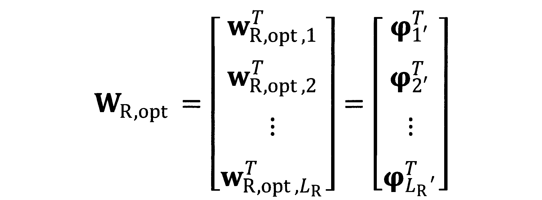
- Transmission BF weight control section 80 L T number of candidate transmission BF weight vector in descending order received power sum P RS1 in a user equipment UE Select the preferred transmission BF weight matrix Is determined (S160).
- the transmission BF weight control unit 80 of the small base station MMNB determines the preferred transmission BF weight matrix determined in step S160.
- the transmission BF weight control unit 80 of the small base station MMNB determines the preferred transmission BF weight matrix determined in step S160.
- transmission beamforming is performed on a reference signal that has not been precoded and transmitted.
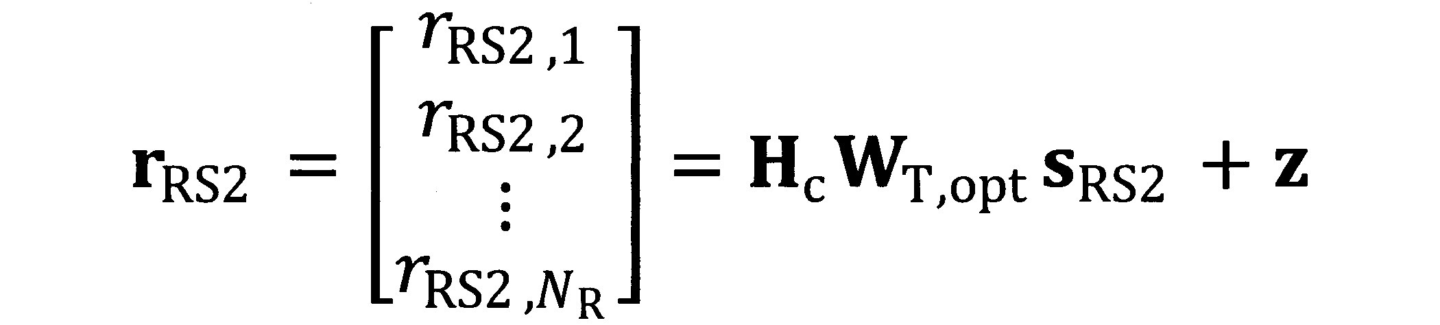
- the reference signal transmitted in step S200 May be referred to as a second reference signal RS2.
- Received signal vector of N R rows and one column received by N R receive antennas A R Are branched and input to LR receive beamforming circuits RBC included in the receive beamforming unit 112, respectively.
- the user equipment receives BF weight controller 160 of the UE as in step S120 described above, to perform a receive beamforming in a time division to the received signal vector, the receiving beam forming unit 112 (L R number of receive beamforming circuit RBC ) To control.
- the description of each value in the above formula is the same as that described above (Item 1 (4) -1).
- L R number of receive beamforming circuit RBC based on the control of the reception BF weight control section 160, by executing a time-division or more receive beamforming over (N R / L R) times, N R rows 1 Received BF output vector of column Is generated (S210). That, L R number of receive beamforming circuit RBC is generated in a time division the N R orthogonal reception beam, receiving a second reference signal RS2. Similarly to the above, or more the N R received quadrature BF weight vector are orthogonal to each other.
- the arithmetic processing unit 150 selects L R number of receiving BF output components to the received power is high order, L R-number of reception quadrature BF weight vector corresponding to the selected received BF weights output components Preferred receive BF weight matrix Is determined (S230).
- the components in the preferred reception BF weight matrix do not overlap each other, that is, the following equation (3) To be satisfied.
- the preferred received BF weight matrix includes LR received orthogonal BF weight vectors that are independent of each other.
- Transmission BF weight control section 80 of the small base station MMNB is preferably transmits subjected to analog transmit beamforming reference signal based on the BF weight matrix to transmit from the N T transmit antennas A T, transmission beam forming unit 54 Is controlled (S300).
- the reference signal transmitted in step S300 May be referred to as a third reference signal RS3.
- the user equipment receives BF weight controller 160 of the UE, to the third reference signal RS3 which is received by the receiving antenna A R, based on preferred reception BF weight matrix to perform a analog receive beamforming, the receiving beam forming unit 112 is controlled (S310).
- the third reference signal RS3 received by the reception beamforming unit 112 is input to the arithmetic processing unit 150 through the down-conversion unit 114 and the AD conversion unit 120.
- the arithmetic processing unit 150 uses the input third reference signal RS3 to calculate an equivalent channel matrix. Is estimated (S320).
- the above equivalent channel matrix is a characteristic matrix indicating signal changes due to transmission beamforming, spatial propagation (channel matrix), and reception beamforming.
- the above estimation of the equivalent channel matrix is performed in the same manner as general channel estimation. For example, estimation of an equivalent channel matrix using the least square method can be employed.
- the estimated equivalent channel matrix is fed back from the user apparatus UE to the small base station MMNB via the feedback unit 180 (S330).
- a suitable precoding matrix and a suitable postcoding matrix are determined using the estimated equivalent channel matrix.
- the preferred precoding matrix is determined by the small base station MMNB (S340), and the preferred postcoding matrix is determined by the user apparatus UE (S350). More specifically, it is as follows.
- Equation (4) The equivalent channel matrix is subjected to singular value decomposition as shown in Equation (4) below.
- the left singular matrix And right singular matrix Are unitary matrices of M rows and M columns, and singular value matrices Is the equivalent channel matrix Is a diagonal matrix of M rows and M columns having a singular value as a diagonal component.
- the transmission BF weight control unit 80 of the small base station MMNB is The precoding matrix is determined as follows, and the reception BF weight control unit 160 of the user apparatus UE is A suitable post-coding matrix is determined as follows. As a result of the above determination, an eigenmode channel is formed on the MIMO transmission path, so that M streams can be separated from each other.
- a suitable post-coding matrix can be determined based on the MMSE (least square error) criterion as described below.
- the preferred precoding matrix is determined by singular value decomposition as described above. According to the MMSE norm, the preferred post-coding matrix is expressed as the following equation (5).
- ⁇ is the received SNR
- the estimation error of the equivalent channel matrix can be reduced by using the received SNR. Therefore, it is possible to determine a suitable post-coding matrix with higher accuracy.
- precoding and postcoding based on a codebook which is a conventional technique, may be employed.
- the weight matrix is determined in stages. That is, the preferred transmission BF weight and the preferred reception BF weight are determined first, and the preferred precoding weight and the preferred postcoding weight are determined based on them. Therefore, the number of combinations to be calculated is suppressed as compared to a configuration in which all combinations of weight matrices (transmission BF weight, reception BF weight, precoding weight, and postcoding weight) are determined by trial. As a result, a suitable weight matrix is determined while reducing the amount of calculation required for determining the weight matrix.
- the user apparatus UE also in the first stage of determining the preferred transmission BF weight, the user apparatus UE generates an orthogonal beam by beam forming and receives the reference signal.
- a reception beamforming gain can be obtained, so that a suitable transmission BF weight can be selected with higher accuracy.
- FIG. 10 and FIG. 12 are operation flows showing the weight matrix determination of the present embodiment.
- Step S100 candidate transmission BF weight vector
- step S120 generation of received BF output vector
- the received BF output vector of NR rows and 1 column is executed. Is generated.
- Transmission BF weight control section 80 of the small base station MMNB is, L T number of candidate transmission BF weight vector in order of received power sum P RS1 greater in a user equipment UE Select the preferred transmission BF weight matrix Is determined (S160).
- Step S200 transmission of the second reference signal
- step S210 generation of the reception BF output vector
- the reception BF output vector of N R rows and 1 column Is generated and input to the arithmetic processing unit 150.
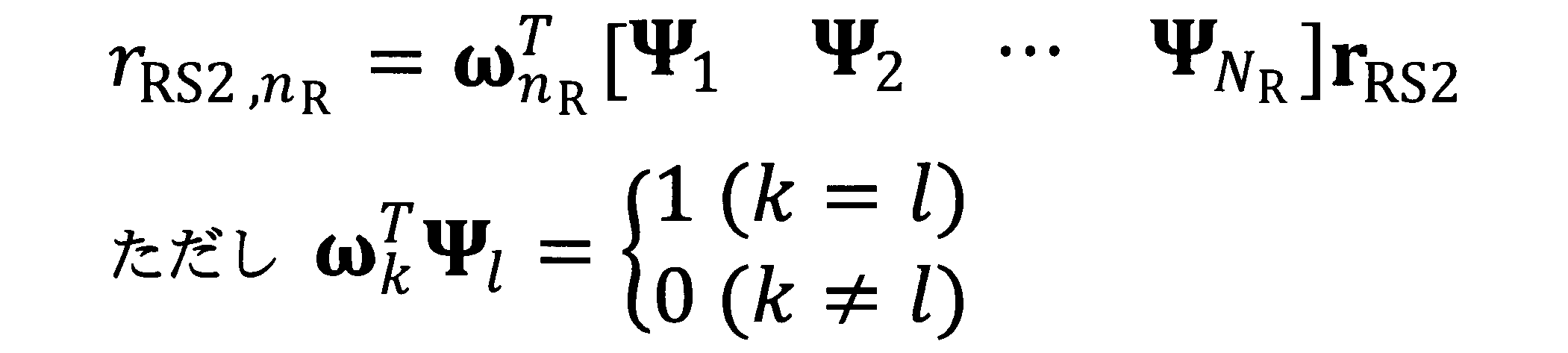
- the above received BF output vector is expressed as follows.
- the arithmetic processing unit 150 receives the reception orthogonal BF weight vector. Respect, separation operator corresponding to the n R th reception antenna A R The multiplied from the left by (i.e., separating operation to run) that it is possible to separate the received signal in the n R th reception antenna A R.
- the separation operation is expressed by the following expression.
- the separation operator is set as follows:
- Processing unit 150 by executing all of the above separation operations N R receive antennas A R, the reception BF output vector of N R rows and one column To N R rows and 1 column received signal vector Is acquired (S222).
- the arithmetic processing unit 150 obtains the received signal vector Use the channel matrix Is estimated (S232).
- the above channel matrix is a characteristic matrix indicating signal changes due to transmission beamforming and spatial propagation.
- the above estimation of the channel matrix is performed in the same manner as general channel estimation. For example, channel matrix estimation using the least square method can be employed.
- the arithmetic processing unit 150 selects a candidate received BF weight vector from a plurality (Y (Y ⁇ M (number of streams))) of received BF weight vectors stored in the storage unit 190. Is selected (S242). Any vector may be employed as a candidate for the received BF weight vector. For example, a plurality of steering vectors may be adopted as received BF weight vector candidates.
- the arithmetic processing unit 150 calculates the estimated channel matrix. Using the received power F (Frobenius norm) of the selected candidate received BF weight vector Is calculated (S252).
- step S262 when arithmetic processing unit 150 determines that all the received BF weight vector candidates have not yet been selected (S262: NO), the process returns to step S242, and a new candidate received BF weight vector is determined. The received power F is selected. In the present example where there are Y received BF weight vector candidates, the above steps are repeated Y times.
- L R number of candidate reception weight vectors in the order received power F is higher in a user equipment UE Select the preferred received BF weight matrix Is determined (S272).
- the reception orthogonal BF weight vector corresponding to the phase offset ⁇ k is expressed by the following equation. Note that the number K of phase offsets ⁇ and the difference ( ⁇ (k + 1) ⁇ k ) are arbitrarily determined.
- step S130 received power sum PRS1 is calculated for each of the K received BF output vectors. Then, in step S140, the highest received power sum P RS1 is fed back to the small base station MMNB.
- step S220 N R number of (i.e., a total of (K ⁇ N R) pieces of) included in each of the K received BF output vector for the received BF output components, each received power is calculated.
- step S230 LR received BF output components are selected in descending order of received power, and the preferred received BF weight matrix is determined as described above.
- FIG. 13 is a diagram illustrating a detailed configuration of the reception beamforming circuit RBC of the present modification.
- the reception beam forming circuit RBC included in the received beam forming section 112 under the control of the reception BF weight control section 160, one of the N R present input from the reception antenna A R (i.e., A bypass circuit for selecting one of the elements of the received signal vector of N R rows and 1 column.
- L R number of receive beamforming circuit RBC included in the received beam forming section 112 executes a bypass receiving operation for obtaining the elements of the received signal vector corresponding to the receiving antenna A R of L R present.
- N R / L R time-division over the bypass receive operation
- N R rows and one column of the received signal containing the elements of the received signal vector corresponding to N R receive antennas A R vector Are obtained directly (ie, without performing a separation operation).
- the above receiving operation of this modification is executed in place of steps S210 to S222 of the second embodiment. Other operations are executed in the same manner as in the second embodiment.
- Modification 3 Transmission beam forming section 54 of the small base station MMNB may be a Furuare type structure in which one transmit beam is generated using all the transmission antennas A T of the N T, is blocked (N T / L T ) A sub-array configuration in which one transmission beam is generated by using the number of transmission antennas A T may be used.
- the reception beam forming unit 112 of the user equipment UE may be a Furuare type structure in which one of the receive beams are generated using all of the receiving antennas A R of the N R present, are blocked (N R / L R) of the transmitting antenna a R of the present may be subarray type structure in which one of the receive beams are generated using.
- the scale of analog circuits (variable phase shifter PS, adder AD, etc.) can be reduced. As a result, loss due to the analog circuit is reduced and the manufacturing cost of the device is reduced.
- control information (such as feedback information) between the small base station MMNB and the user apparatus UE can be performed by an arbitrary route.
- control information may be exchanged by directly transmitting and receiving radio signals.
- the small base station MMNB and the user apparatus UE may transmit / receive control information via the macro base station MeNB.
- Modification 5 The configuration in the above embodiment can be applied to a multi-user environment. In this modification, in order to realize multiplexing between multiple users, it is preferable to suppress interference between users by performing precoding based on block diagonalization.
- rank adaptation that adaptively controls the number of transmission streams can be applied. For example, when a maximum of M streams can be transmitted between the small base station MMNB and the user apparatus UE, the preferred transmission BF weight matrix and the preferred reception BF weight matrix are determined for all M streams. It is possible to determine the number of transmission streams that maximize the channel capacity C.
- the small base station MMNB is illustrated as a transmitter, and the user apparatus UE is illustrated as a receiver.
- the user apparatus UE may function as a transmitting apparatus, and the small base station MMNB may function as a receiving apparatus. That is, the above-described weight matrix determination can be applied to uplink transmission.
- a preferred BF weight matrix is determined for downlink transmission.
- TDD time division duplex
- FDD frequency division duplex
- a preferred BF weight matrix is determined. It is preferable to determine the preferred BF weight matrix from the one having a larger number of antennas on the transmission side (that is, downlink transmission) with beamforming gain.
- a suitable transmission BF weight (vector, matrix) is determined on the transmission side (small base station MMNB), and a suitable reception BF weight (vector, matrix) is determined on the reception side (user apparatus UE).
- weight determination can be performed at any location in the wireless communication system 1.
- the preferred reception BF weight may be determined on the transmission side, or the preferred transmission BF weight may be determined on the reception side.
- the transmitting side determines a suitable precoding matrix
- the receiving side determines a suitable postcoding matrix
- the preferred precoding matrix and the preferred postcoding matrix may be determined on either the transmission side or the reception side.
- the number L R of the receive beamformer RBC is preferable that is a divisor of the number N R receive antennas A R. If, when the case where the number of division processing (N R / L R) is not divisible, it is sufficient to perform the time-division processing for the number of times the decimal portion of the N R / L R.
- the user apparatus UE is an arbitrary apparatus capable of wireless communication with a base station (macro base station MeNB, small base station MMNB) in the network.
- the user apparatus UE may be, for example, a mobile phone terminal such as a feature phone or a smartphone, a tablet terminal, a desktop personal computer, a notebook personal computer, a UMPC (Ultra-Mobile Personal Computer), It may be a game machine or other wireless terminal.
- Each function executed by the CPU in each element (user apparatus UE and small base station MMNB) in the wireless communication system 1 may be executed by hardware instead of the CPU, for example, an FPGA (Field Programmable Gate Array) It may be executed by a programmable logic device such as a DSP (Digital Signal Processor).
- FPGA Field Programmable Gate Array
- DSP Digital Signal Processor
Abstract
Description
1(1). Massive-MIMO伝送
本発明の第1実施形態に係るMassive-MIMO伝送方式について説明する。基地局が多数の送信アンテナATを用いて無線通信を実行するMassive-MIMO伝送方式においては、多重化による高い無線通信速度(データレート)が実現される。また、ビームフォーミングを行う際のアンテナ制御の自由度が高まるため、従来よりも高度なビームフォーミングが実現される。そのため、干渉量の低減や無線リソースの有効利用が実現される。なお、Massive-MIMOに適応した基地局が備える送信アンテナATの数は、以下に限定されるものではないが、32本以上、64本以上、96本以上、100本以上、128本以上、192本以上、200本以上、256本以上、500本以上、512本以上、1000本以上、または1024本以上であると好適である。 1. First Embodiment 1 (1). Massive-MIMO transmission A Massive-MIMO transmission scheme according to the first embodiment of the present invention will be described. In the Massive-MIMO transmission scheme in which the base station performs wireless communication using a large number of transmission antennas AT , a high wireless communication speed (data rate) by multiplexing is realized. In addition, since the degree of freedom of antenna control when performing beam forming increases, higher beam forming than before is realized. Therefore, reduction of interference amount and effective use of radio resources are realized. Note that the number of transmission antennas AT included in the base station adapted for Massive-MIMO is not limited to the following, but is 32 or more, 64 or more, 96 or more, 100 or more, 128 or more, It is preferable that the number is 192 or more, 200 or more, 256 or more, 500 or more, 512 or more, 1000 or more, or 1024 or more.
Massive-MIMO伝送の信号処理においては、上述した複数のウェイト行列
図10および図11は、本実施形態のウェイト行列決定を示す動作フローである。概略的には、本実施形態のウェイト行列決定によれば、第1段階(好適送信BFウェイトベクトルの決定,ステップS100~S160)と第2段階(好適受信BFウェイトベクトルの決定,ステップS200~S230)とが実行される結果、好適な(すなわち、試行された範囲においては最適な)送信BFウェイト行列

以下、BFウェイトの決定を詳細に説明する。BFウェイトの決定が開始すると、スモール基地局MMNBの送信BFウェイト制御部80が、記憶部90に記憶された複数(X個)の送信BFウェイトベクトルの候補から、候補送信BFウェイトベクトル


動作フローは図11に続く。スモール基地局MMNBの送信BFウェイト制御部80は、ステップS160にて決定された好適送信BFウェイト行列


以上のように決定された好適送信BFウェイト行列

以上の本実施形態の構成によれば、ウェイト行列が段階的に決定される。すなわち、好適送信BFウェイトと好適受信BFウェイトとが先に決定され、それらに基づいて好適プリコーディングウェイトと好適ポストコーディングウェイトとが決定される。したがって、ウェイト行列(送信BFウェイト、受信BFウェイト、プリコーディングウェイト、およびポストコーディングウェイト)の組合せを全て試行して決定する構成と比較して、演算対象となる組合せ数が抑制される。結果として、ウェイト行列決定に要する演算量が低減されつつ、好適なウェイト行列が決定される。 1 (5). Effects of this Embodiment According to the configuration of this embodiment described above, the weight matrix is determined in stages. That is, the preferred transmission BF weight and the preferred reception BF weight are determined first, and the preferred precoding weight and the preferred postcoding weight are determined based on them. Therefore, the number of combinations to be calculated is suppressed as compared to a configuration in which all combinations of weight matrices (transmission BF weight, reception BF weight, precoding weight, and postcoding weight) are determined by trial. As a result, a suitable weight matrix is determined while reducing the amount of calculation required for determining the weight matrix.
本発明の第2実施形態を以下に説明する。以下に例示する各実施形態において、作用、機能が第1実施形態と同等である要素については、以上の説明で参照した符号を流用して各々の説明を適宜に省略する。 2. Second Embodiment A second embodiment of the present invention will be described below. In each embodiment illustrated below, about the element which an effect | action and a function are equivalent to 1st Embodiment, the code | symbol referred by the above description is diverted and each description is abbreviate | omitted suitably.
図10および図12は、本実施形態のウェイト行列決定を示す動作フローである。第1段階(ステップS100~S160)と第2段階(ステップS200~S272)とが実行される結果、好適な送信BFウェイト行列

好適送信BFウェイト行列は、第1実施形態と同様に決定される(図10)。ステップS100(候補送信BFウェイトベクトル


ステップS200(第2参照信号の送信)およびステップS210(受信BF出力ベクトルの生成)が第1実施形態と同様に実行され、NR行1列の受信BF出力ベクトル


以上のように決定された好適送信BFウェイト行列
以上の本実施形態の構成によれば、第1実施形態と同様の技術的効果が奏される。さらに、受信BFウェイトベクトルの候補が任意に採用され得るので、より柔軟に好適受信BFウェイト行列を設定することが可能である。 2 (2). Effects of this Embodiment According to the configuration of this embodiment described above, the same technical effects as those of the first embodiment are exhibited. Furthermore, since a candidate for the reception BF weight vector can be arbitrarily adopted, it is possible to set a suitable reception BF weight matrix more flexibly.
以上の実施形態は多様に変形される。具体的な変形の態様を以下に例示する。以上の実施の形態および以下の例示から任意に選択された2以上の態様は、相互に矛盾しない限り適宜に併合され得る。 3. Modifications The above embodiment can be variously modified. Specific modifications are exemplified below. Two or more aspects arbitrarily selected from the above embodiments and the following examples can be appropriately combined as long as they do not contradict each other.
以上の実施形態では、LR個の受信ビームフォーミング回路RBCが、受信ビームフォーミングを(NR/LR)回にわたって時分割で実行することにより、NR行1列の受信BF出力ベクトルを生成する(ステップS120,S210)。本変形例では、以上のステップの各々において、1回の時分割処理ごとに、LR個の受信直交BFウェイトベクトルに対してK個の位相オフセットδ1,2,…の各々が加えられることにより、受信BF出力ベクトルの要素となるLR個の受信BF出力成分が位相オフセットδ1,2,…ごとに取得される。以上の時分割処理が(NR/LR)回にわたって繰り返されることにより、位相オフセットδ1,2,…の各々に対応するK個のNR行1列の受信BF出力ベクトルが生成される。 3 (1).
In the above embodiments, by L R number of receive beamforming circuit RBC is performed in time division reception beam forming over (N R / L R) times, generate a reception BF output vector of N R rows and one column (Steps S120 and S210). In this modification, in each of the above steps, each of the K phase offsets δ 1, 2,... Is added to the LR received orthogonal BF weight vectors for each time division process. Thus, LR received BF output components that are elements of the received BF output vector are acquired for each phase offset δ 1, 2 ,. The above time division processing is repeated (N R / L R ) times , thereby generating K N R rows and 1 column received BF output vectors corresponding to each of the phase offsets δ 1, 2 ,. .
第2実施形態では、演算処理部150が分離演算を実行することにより、NR行1列の受信BF出力ベクトル

In the second embodiment, when the

スモール基地局MMNBの送信ビームフォーミング部54は、NT本の送信アンテナATを全て用いて1つの送信ビームが生成されるフルアレー型構成であってもよいし、ブロック化された(NT/LT)本の送信アンテナATを用いて1つの送信ビームが生成されるサブアレー型構成であってもよい。同様に、ユーザ装置UEの受信ビームフォーミング部112は、NR本の受信アンテナARを全て用いて1つの受信ビームが生成されるフルアレー型構成であってもよいし、ブロック化された(NR/LR)本の送信アンテナARを用いて1つの受信ビームが生成されるサブアレー型構成であってもよい。 3 (3). Modification 3
Transmission
以上の実施形態において、スモール基地局MMNBとユーザ装置UEとの制御情報(フィードバック情報など)の通信は、任意のルートにて実行され得る。例えば、スモール基地局MMNBとユーザ装置UEとの間に無線リンクが確立されている場合には、無線信号を直接的に送受信することで制御情報を交換してもよい。また、以上の無線リンクが確立されていない場合には、マクロ基地局MeNB経由でスモール基地局MMNBとユーザ装置UEとが制御情報を送受信してもよい。 3 (4). Modification 4
In the above embodiment, communication of control information (such as feedback information) between the small base station MMNB and the user apparatus UE can be performed by an arbitrary route. For example, when a radio link is established between the small base station MMNB and the user apparatus UE, control information may be exchanged by directly transmitting and receiving radio signals. Moreover, when the above radio link is not established, the small base station MMNB and the user apparatus UE may transmit / receive control information via the macro base station MeNB.
以上の実施形態における構成を、マルチユーザ環境に適用することが可能である。本変形例においては、マルチユーザ間の多重を実現するために、ブロック対角化に基づくプリコーディングを行うことによりユーザ間の干渉を抑制すると好適である。 3 (5). Modification 5
The configuration in the above embodiment can be applied to a multi-user environment. In this modification, in order to realize multiplexing between multiple users, it is preferable to suppress interference between users by performing precoding based on block diagonalization.
以上の実施形態において、送信ストリーム数を適応的に制御するランクアダプテーションを適用することが可能である。例えば、スモール基地局MMNBとユーザ装置UEとの間で最大M本のストリームを伝送できる場合において、好適送信BFウェイト行列及び好適受信BFウェイト行列をM本のストリーム全てについて決定しておくことで、チャネル容量Cを最大化させる送信ストリーム数を決定することが可能である。 3 (6). Modification 6
In the above embodiment, rank adaptation that adaptively controls the number of transmission streams can be applied. For example, when a maximum of M streams can be transmitted between the small base station MMNB and the user apparatus UE, the preferred transmission BF weight matrix and the preferred reception BF weight matrix are determined for all M streams. It is possible to determine the number of transmission streams that maximize the channel capacity C.
以上の実施形態においては、送信機としてスモール基地局MMNBが例示され、受信機としてユーザ装置UEが例示される。しかしながら、前述のウェイト行列決定において、ユーザ装置UEが送信側の装置として機能し、スモール基地局MMNBが受信側の装置として機能してもよい。すなわち、上りリンク伝送に関しても前述のウェイト行列決定が適用され得る。 3 (7). Modification 7
In the above embodiment, the small base station MMNB is illustrated as a transmitter, and the user apparatus UE is illustrated as a receiver. However, in the above-described weight matrix determination, the user apparatus UE may function as a transmitting apparatus, and the small base station MMNB may function as a receiving apparatus. That is, the above-described weight matrix determination can be applied to uplink transmission.
以上の実施形態においては、下りリンク伝送について好適BFウェイト行列が決定される。無線通信システム1に時分割複信(Time Division Duplex,TDD)が採用される場合には、上りリンクと下りリンクとで共通の周波数が用いられるので、下りリンク伝送について決定された好適BFウェイト行列を、上りリンク伝送にも使用することが可能である。他方、無線通信システム1に周波数分割複信(Frequency Division Duplex,FDD)が採用される場合には、下りリンク伝送について好適BFウェイト行列を決定した後に、上りリンク伝送についても前述の実施形態と同様に好適BFウェイト行列を決定する。ビームフォーミング利得をして、送信側のアンテナ数が多い方(すなわち、下りリンク伝送)から好適BFウェイト行列を決定すると好適である。 3 (8). Modification 8
In the above embodiment, a preferred BF weight matrix is determined for downlink transmission. When time division duplex (TDD) is adopted in the
以上の実施形態では、送信側(スモール基地局MMNB)にて好適送信BFウェイト(ベクトル、行列)が決定され、受信側(ユーザ装置UE)にて好適受信BFウェイト(ベクトル、行列)が決定される。しかしながら、無線通信システム1内の任意の箇所でウェイト決定が実行され得る。例えば、送信側で好適受信BFウェイトが決定されてもよいし、受信側で好適送信BFウェイトが決定されてもよい。 3 (9). Modification 9
In the above embodiment, a suitable transmission BF weight (vector, matrix) is determined on the transmission side (small base station MMNB), and a suitable reception BF weight (vector, matrix) is determined on the reception side (user apparatus UE). The However, weight determination can be performed at any location in the
受信ビームフォーミング回路RBCの個数LRは、受信アンテナARの本数NRの約数であると好適である。もし、時分割処理の回数(NR/LR)が割り切れない場合は、NR/LRの小数点以下を切り上げた回数だけ時分割処理を実行すればよい。 3 (10).
The number L R of the receive beamformer RBC is preferable that is a divisor of the number N R receive antennas A R. If, when the case where the number of division processing (N R / L R) is not divisible, it is sufficient to perform the time-division processing for the number of times the decimal portion of the N R / L R.
ユーザ装置UEは、ネットワーク内の基地局(マクロ基地局MeNB、スモール基地局MMNB)と無線通信が可能な任意の装置である。ユーザ装置UEは、例えば、フィーチャーフォンまたはスマートフォン等の携帯電話端末でもよく、タブレット端末でもよく、デスクトップ型パーソナルコンピュータでもよく、ノート型パーソナルコンピュータでもよく、UMPC(Ultra-Mobile Personal Computer)でもよく、携帯用ゲーム機でもよく、その他の無線端末でもよい。 3 (11). Modification 11
The user apparatus UE is an arbitrary apparatus capable of wireless communication with a base station (macro base station MeNB, small base station MMNB) in the network. The user apparatus UE may be, for example, a mobile phone terminal such as a feature phone or a smartphone, a tablet terminal, a desktop personal computer, a notebook personal computer, a UMPC (Ultra-Mobile Personal Computer), It may be a game machine or other wireless terminal.
無線通信システム1内の各要素(ユーザ装置UEおよびスモール基地局MMNB)においてCPUが実行する各機能は、CPUの代わりに、ハードウェアで実行してもよいし、例えばFPGA(Field Programmable Gate Array)、DSP(Digital Signal Processor)等のプログラマブルロジックデバイスで実行してもよい。 3 (12). Modification 12
Each function executed by the CPU in each element (user apparatus UE and small base station MMNB) in the
DESCRIPTION OF
Claims (8)
- プリコーディング行列を用いてプリコーディングを施すプリコーディング部と、
前記プリコーディングが施された後の信号に対して、送信BF(ビームフォーミング)ウェイト行列に相当する位相および振幅の変化を付与する送信ビームフォーミングを施す送信ビームフォーミング部と、
前記送信ビームフォーミングが施された信号を送信するNT本の送信アンテナと
を備える送信機と、
前記送信機から送信され空間を伝搬した信号を受信するNR本の受信アンテナと、
複数の前記受信アンテナが受信した前記信号に対して、受信BFウェイト行列に相当する位相および振幅の変化を付与する受信ビームフォーミングを施す受信ビームフォーミング部と、
前記アナログ受信ビームフォーミングが施された後の信号に対して、ポストコーディング行列を用いてポストコーディングを施すポストコーディング部と
を備える受信機とを備える無線通信システムにおける無線通信制御方法であって、
NR本の前記受信アンテナにて受信された受信信号ベクトルに対し、前記受信ビームフォーミング部が備えるLR個の受信ビームフォーミング回路が、受信ビームフォーミングを(NR/LR)回にわたって実行することにより、NR個の受信BF出力成分を有する受信BF出力ベクトルを生成することと、
NR個の前記受信BF出力成分の各々について受信電力を算定することと、
受信電力が高い順にLR個の前記受信BF出力成分を選択し、選択された当該受信BF出力成分に対応するLR個の受信直交BFウェイトベクトルを含む好適受信BFウェイト行列を決定することとを備える
無線通信制御方法。 A precoding unit that performs precoding using a precoding matrix;
A transmission beamforming unit that performs transmission beamforming to give a phase and amplitude change corresponding to a transmission BF (beamforming) weight matrix to the signal after the precoding is performed;
A transmitter comprising: NT transmission antennas for transmitting the signals subjected to the transmission beamforming;
And N R receive antennas present to receive a signal propagating through space are transmitted from the transmitter,
A reception beamforming unit that performs reception beamforming that gives a change in phase and amplitude corresponding to a reception BF weight matrix to the signals received by the plurality of reception antennas;
A radio communication control method in a radio communication system comprising: a receiver comprising: a post-coding unit that performs post-coding using a post-coding matrix on a signal after being subjected to the analog reception beam forming,
On the received signal vector received by the N R receive antennas present, reception beam forming circuit L R number of the receiving beam forming unit is provided executes a reception beam forming over (N R / L R) times Generating a received BF output vector having N R received BF output components;
Calculating received power for each of the N R received BF output components;
Selecting LR received BF output components in descending order of received power, and determining a preferred received BF weight matrix including LR received orthogonal BF weight vectors corresponding to the selected received BF output components; A wireless communication control method. - プリコーディング行列を用いてプリコーディングを施すプリコーディング部と、
前記プリコーディングが施された後の信号に対して、送信BFウェイト行列に相当する位相および振幅の変化を付与する送信ビームフォーミングを施す送信ビームフォーミング部と、
前記送信ビームフォーミングが施された信号を送信するNT本の送信アンテナと
を備える送信機と、
前記送信機から送信され空間を伝搬した信号を受信するNR本の受信アンテナと、
複数の前記受信アンテナが受信した前記信号に対して、受信BFウェイト行列に相当する位相および振幅の変化を付与する受信ビームフォーミングを施す受信ビームフォーミング部と、
前記アナログ受信ビームフォーミングが施された後の信号に対して、ポストコーディング行列を用いてポストコーディングを施すポストコーディング部と
を備える受信機とを備える無線通信システムにおける無線通信制御方法であって、
NR本の前記受信アンテナにて受信された受信信号ベクトルに対し、前記受信ビームフォーミング部が備えるLR個の受信ビームフォーミング回路が、受信ビームフォーミングを(NR/LR)回にわたって実行することにより、NR個の受信BF出力成分を有する受信BF出力ベクトルを生成することと、
前記受信BF出力ベクトルに対して、NR本の前記受信アンテナに対応するNR個の分離演算子をそれぞれ乗算することにより、前記受信信号ベクトルを取得することと、
前記受信信号ベクトルを用いてチャネル行列を推定することと、
推定された前記チャネル行列を用いて、複数の受信BFウェイトベクトルの候補の各々について受信電力を算定することと、
受信電力が高い順にLR個の前記受信BFウェイトベクトルの候補を選択し、選択されたLR個の前記受信BFウェイトベクトルの候補を含む好適受信BFウェイト行列を決定することとを備える
無線通信制御方法。 A precoding unit that performs precoding using a precoding matrix;
A transmission beamforming unit that performs transmission beamforming that gives a change in phase and amplitude corresponding to a transmission BF weight matrix to the signal after being subjected to the precoding;
A transmitter comprising: NT transmission antennas for transmitting the signals subjected to the transmission beamforming;
And N R receive antennas present to receive a signal propagating through space are transmitted from the transmitter,
A reception beamforming unit that performs reception beamforming that gives a change in phase and amplitude corresponding to a reception BF weight matrix to the signals received by the plurality of reception antennas;
A radio communication control method in a radio communication system comprising: a receiver comprising: a post-coding unit that performs post-coding using a post-coding matrix on a signal after being subjected to the analog reception beam forming,
On the received signal vector received by the N R receive antennas present, reception beam forming circuit L R number of the receiving beam forming unit is provided executes a reception beam forming over (N R / L R) times Generating a received BF output vector having N R received BF output components;
To the received BF output vector is multiplied by the N R number of separation operator corresponding to the N R receive antennas present respectively, and obtaining the received signal vector,
Estimating a channel matrix using the received signal vector;
Calculating received power for each of a plurality of received BF weight vector candidates using the estimated channel matrix;
Selecting LR received BF weight vector candidates in descending order of received power, and determining a preferred received BF weight matrix including the selected LR received BF weight vector candidates. Control method. - プリコーディング行列を用いてプリコーディングを施すプリコーディング部と、
前記プリコーディングが施された後の信号に対して、送信BFウェイト行列に相当する位相および振幅の変化を付与する送信ビームフォーミングを施す送信ビームフォーミング部と、
前記送信ビームフォーミングが施された信号を送信するNT本の送信アンテナと
を備える送信機と、
前記送信機から送信され空間を伝搬した信号を受信するNR本の受信アンテナと、
複数の前記受信アンテナが受信した前記信号に対して、受信BFウェイト行列に相当する位相および振幅の変化を付与する受信ビームフォーミングを施す受信ビームフォーミング部と、
前記アナログ受信ビームフォーミングが施された後の信号に対して、ポストコーディング行列を用いてポストコーディングを施すポストコーディング部と
を備える受信機とを備える無線通信システムにおける無線通信制御方法であって、
NR本の前記受信アンテナにて受信された受信信号ベクトルに対し、前記受信ビームフォーミング部が備えるLR個の受信ビームフォーミング回路の各々が、前記受信信号ベクトルの要素の1つを選択して取得するバイパス受信動作を(NR/LR)回にわたって実行することにより、前記受信信号ベクトルを取得することと、
前記受信信号ベクトルを用いてチャネル行列を推定することと、
推定された前記チャネル行列を用いて、複数の受信BFウェイトベクトルの候補の各々について受信電力を算定することと、
受信電力が高い順にLR個の前記受信BFウェイトベクトルの候補を選択し、選択されたLR個の前記受信BFウェイトベクトルの候補を含む好適受信BFウェイト行列を決定することとを備える
無線通信制御方法。 A precoding unit that performs precoding using a precoding matrix;
A transmission beamforming unit that performs transmission beamforming that gives a change in phase and amplitude corresponding to a transmission BF weight matrix to the signal after being subjected to the precoding;
A transmitter comprising: NT transmission antennas for transmitting the signals subjected to the transmission beamforming;
And N R receive antennas present to receive a signal propagating through space are transmitted from the transmitter,
A reception beamforming unit that performs reception beamforming that gives a change in phase and amplitude corresponding to a reception BF weight matrix to the signals received by the plurality of reception antennas;
A radio communication control method in a radio communication system comprising: a receiver comprising: a post-coding unit that performs post-coding using a post-coding matrix on a signal after being subjected to the analog reception beam forming,
Each of the LR receive beamforming circuits included in the receive beamforming unit selects one of the elements of the receive signal vector for the receive signal vectors received by the NR receive antennas. Obtaining the received signal vector by performing a bypass reception operation to obtain (N R / L R ) times;
Estimating a channel matrix using the received signal vector;
Calculating received power for each of a plurality of received BF weight vector candidates using the estimated channel matrix;
Selecting LR received BF weight vector candidates in descending order of received power, and determining a preferred received BF weight matrix including the selected LR received BF weight vector candidates. Control method. - 前記好適受信BFウェイト行列を決定することに先立ち、
複数の送信BFウェイトベクトルの候補から、候補送信BFウェイトベクトルを選択することと、
選択された前記候補送信BFウェイトベクトルを含む候補送信BFウェイト行列に基づいてアナログ送信ビームフォーミングが施された参照信号を、NT本の前記送信アンテナから送信することと、
NR本の前記受信アンテナにて受信された前記参照信号に対応する受信信号ベクトルに対し、LR個の前記受信ビームフォーミング回路が、受信ビームフォーミングを(NR/LR)回にわたって実行することにより、NR個の受信BF出力成分を有する受信BF出力ベクトルを生成することと、
前記受信BF出力ベクトルの受信電力和を算定することと、
前記選択すること、前記送信すること、前記生成すること、および前記算定することを複数の前記送信BFウェイトベクトルの候補について実行することにより複数の受信電力和を取得することと、
受信電力和が高い順にLT個の前記送信BFウェイトベクトルの候補を選択し、選択されたLT個の前記送信BFウェイトベクトルの候補を含む好適送信BFウェイト行列を決定することとをさらに備える
請求項1から3のいずれかの無線通信制御方法。 Prior to determining the preferred received BF weight matrix,
Selecting a candidate transmission BF weight vector from a plurality of transmission BF weight vector candidates;
Transmitting the reference signal subjected to the analog transmission beamforming based on the candidate transmission BF weight matrix including the selected candidate transmission BF weight vector from the N T transmitting antennas;
On the received signal vector corresponding to the N R present the reference signal received by the receiving antenna, L R-number of the reception beam forming circuit executes a reception beam forming over (N R / L R) times Generating a received BF output vector having N R received BF output components;
Calculating a received power sum of the received BF output vector;
Obtaining a plurality of received power sums by performing the selecting, transmitting, generating, and calculating for a plurality of transmission BF weight vector candidates;
Selects a candidate of L T number of the transmission BF weight vector to the received power sum descending order, further comprising determining a suitable transmission BF weighting matrix comprising a candidate of the selected L T number of the transmission BF weight vector The wireless communication control method according to claim 1. - 前記好適送信BFウェイト行列に基づいてアナログ送信ビームフォーミングが施された参照信号を前記送信機から送信することと、
前記受信機にて受信された前記参照信号に対して、前記好適受信BFウェイト行列に基づいてアナログ受信ビームフォーミングを施した結果を示す等価チャネル行列を推定することと、
推定された前記等価チャネル行列に基づいて、好適プリコーディング行列および好適ポストコーディング行列を決定することとをさらに備える
請求項4の無線通信制御方法。 Transmitting a reference signal subjected to analog transmission beamforming based on the preferred transmission BF weight matrix from the transmitter;
Estimating an equivalent channel matrix indicating a result of performing analog reception beamforming on the reference signal received by the receiver based on the preferred reception BF weight matrix;
The wireless communication control method according to claim 4, further comprising: determining a suitable precoding matrix and a suitable postcoding matrix based on the estimated equivalent channel matrix. - プリコーディング行列を用いてプリコーディングを施すプリコーディング部と、
前記プリコーディングが施された後の信号に対して、送信BF(ビームフォーミング)ウェイト行列に相当する位相および振幅の変化を付与する送信ビームフォーミングを施す送信ビームフォーミング部と、
前記送信ビームフォーミングが施された信号を送信するNT本の送信アンテナと
を備える送信機と、
前記送信機から送信され空間を伝搬した信号を受信するNR本の受信アンテナと、
複数の前記受信アンテナが受信した前記信号に対して、受信BFウェイト行列に相当する位相および振幅の変化を付与する受信ビームフォーミングを施す受信ビームフォーミング部と、
前記アナログ受信ビームフォーミングが施された後の信号に対して、ポストコーディング行列を用いてポストコーディングを施すポストコーディング部と
を備える受信機とを備え、
前記受信ビームフォーミング部は、
NR本の前記受信アンテナにて受信された受信信号ベクトルに対し、前記受信ビームフォーミング部が備えるLR個の受信ビームフォーミング回路が、受信ビームフォーミングを(NR/LR)回にわたって実行することにより、NR個の受信BF出力成分を有する受信BF出力ベクトルを生成し、
前記受信機は、
NR個の前記受信BF出力成分の各々について受信電力を算定し、
受信電力が高い順にLR個の前記受信BF出力成分を選択し、選択された当該受信BF出力成分に対応するLR個の受信直交BFウェイトベクトルを含む好適受信BFウェイト行列を決定する演算処理部をさらに備える
無線通信システム。 A precoding unit that performs precoding using a precoding matrix;
A transmission beamforming unit that performs transmission beamforming to give a phase and amplitude change corresponding to a transmission BF (beamforming) weight matrix to the signal after the precoding is performed;
A transmitter comprising: NT transmission antennas for transmitting the signals subjected to the transmission beamforming;
And N R receive antennas present to receive a signal propagating through space are transmitted from the transmitter,
A reception beamforming unit that performs reception beamforming that gives a change in phase and amplitude corresponding to a reception BF weight matrix to the signals received by the plurality of reception antennas;
A receiver comprising: a post-coding unit that performs post-coding on a signal after being subjected to the analog reception beamforming using a post-coding matrix;
The reception beamforming unit is
On the received signal vector received by the N R receive antennas present, reception beam forming circuit L R number of the receiving beam forming unit is provided executes a reception beam forming over (N R / L R) times To generate a received BF output vector having NR received BF output components,
The receiver
Calculating received power for each of the N R received BF output components;
Arithmetic processing for selecting LR received BF output components in descending order of received power and determining a preferred received BF weight matrix including LR received orthogonal BF weight vectors corresponding to the selected received BF output components. A wireless communication system further comprising a unit. - プリコーディング行列を用いてプリコーディングを施すプリコーディング部と、
前記プリコーディングが施された後の信号に対して、送信BFウェイト行列に相当する位相および振幅の変化を付与する送信ビームフォーミングを施す送信ビームフォーミング部と、
前記送信ビームフォーミングが施された信号を送信するNT本の送信アンテナと
を備える送信機と、
前記送信機から送信され空間を伝搬した信号を受信するNR本の受信アンテナと、
複数の前記受信アンテナが受信した前記信号に対して、受信BFウェイト行列に相当する位相および振幅の変化を付与する受信ビームフォーミングを施す受信ビームフォーミング部と、
前記アナログ受信ビームフォーミングが施された後の信号に対して、ポストコーディング行列を用いてポストコーディングを施すポストコーディング部と
を備える受信機とを備え、
前記受信ビームフォーミング部は、
NR本の前記受信アンテナにて受信された受信信号ベクトルに対し、前記受信ビームフォーミング部が備えるLR個の受信ビームフォーミング回路が、受信ビームフォーミングを(NR/LR)回にわたって実行することにより、NR個の受信BF出力成分を有する受信BF出力ベクトルを生成し、
前記受信機は、
前記受信BF出力ベクトルに対して、NR本の前記受信アンテナに対応するNR個の分離演算子をそれぞれ乗算することにより、前記受信信号ベクトルを取得し、
前記受信信号ベクトルを用いてチャネル行列を推定し、
推定された前記チャネル行列を用いて、複数の受信BFウェイトベクトルの候補の各々について受信電力を算定し、
受信電力が高い順にLR個の前記受信BFウェイトベクトルの候補を選択し、選択されたLR個の前記受信BFウェイトベクトルの候補を含む好適受信BFウェイト行列を決定する演算処理部をさらに備える
無線通信システム。 A precoding unit that performs precoding using a precoding matrix;
A transmission beamforming unit that performs transmission beamforming that gives a change in phase and amplitude corresponding to a transmission BF weight matrix to the signal after being subjected to the precoding;
A transmitter comprising: NT transmission antennas for transmitting the signals subjected to the transmission beamforming;
And N R receive antennas present to receive a signal propagating through space are transmitted from the transmitter,
A reception beamforming unit that performs reception beamforming that gives a change in phase and amplitude corresponding to a reception BF weight matrix to the signals received by the plurality of reception antennas;
A receiver comprising: a post-coding unit that performs post-coding on a signal after being subjected to the analog reception beamforming using a post-coding matrix;
The reception beamforming unit is
On the received signal vector received by the N R receive antennas present, reception beam forming circuit L R number of the receiving beam forming unit is provided executes a reception beam forming over (N R / L R) times To generate a received BF output vector having NR received BF output components,
The receiver
To the received BF output vector is multiplied by the N R number of separation operator corresponding to the N R receive antennas present respectively, obtains the received signal vector,
Estimating a channel matrix using the received signal vector;
Using the estimated channel matrix, calculate received power for each of a plurality of received BF weight vector candidates;
An arithmetic processing unit is further provided that selects LR received BF weight vector candidates in descending order of received power and determines a preferred received BF weight matrix including the selected LR received BF weight vector candidates. Wireless communication system. - プリコーディング行列を用いてプリコーディングを施すプリコーディング部と、
前記プリコーディングが施された後の信号に対して、送信BFウェイト行列に相当する位相および振幅の変化を付与する送信ビームフォーミングを施す送信ビームフォーミング部と、
前記送信ビームフォーミングが施された信号を送信するNT本の送信アンテナと
を備える送信機と、
前記送信機から送信され空間を伝搬した信号を受信するNR本の受信アンテナと、
複数の前記受信アンテナが受信した前記信号に対して、受信BFウェイト行列に相当する位相および振幅の変化を付与する受信ビームフォーミングを施す受信ビームフォーミング部と、
前記アナログ受信ビームフォーミングが施された後の信号に対して、ポストコーディング行列を用いてポストコーディングを施すポストコーディング部と
を備える受信機とを備え、
前記受信ビームフォーミング部が備えるLR個の受信ビームフォーミング回路の各々は、
NR本の前記受信アンテナにて受信された受信信号ベクトルに対し、前記受信信号ベクトルの要素の1つを選択して取得するバイパス受信動作を(NR/LR)回にわたって実行することにより、前記受信信号ベクトルを取得し、
前記受信機は、
前記受信信号ベクトルを用いてチャネル行列を推定し、
推定された前記チャネル行列を用いて、複数の受信BFウェイトベクトルの候補の各々について受信電力を算定し、
受信電力が高い順にLR個の前記受信BFウェイトベクトルの候補を選択し、選択されたLR個の前記受信BFウェイトベクトルの候補を含む好適受信BFウェイト行列を決定する演算処理部をさらに備える
無線通信システム。
A precoding unit that performs precoding using a precoding matrix;
A transmission beamforming unit that performs transmission beamforming that gives a change in phase and amplitude corresponding to a transmission BF weight matrix to the signal after being subjected to the precoding;
A transmitter comprising: NT transmission antennas for transmitting the signals subjected to the transmission beamforming;
And N R receive antennas present to receive a signal propagating through space are transmitted from the transmitter,
A reception beamforming unit that performs reception beamforming that gives a change in phase and amplitude corresponding to a reception BF weight matrix to the signals received by the plurality of reception antennas;
A receiver comprising: a post-coding unit that performs post-coding on a signal after being subjected to the analog reception beamforming using a post-coding matrix;
Each of the LR receive beamforming circuits included in the receive beamforming unit includes:
By performing a bypass reception operation (N R / L R ) times by selecting one of the elements of the received signal vector for the received signal vectors received by the N R receiving antennas. Obtain the received signal vector;
The receiver
Estimating a channel matrix using the received signal vector;
Using the estimated channel matrix, calculate received power for each of a plurality of received BF weight vector candidates;
An arithmetic processing unit is further provided that selects LR received BF weight vector candidates in descending order of received power and determines a preferred received BF weight matrix including the selected LR received BF weight vector candidates. Wireless communication system.
Priority Applications (4)
| Application Number | Priority Date | Filing Date | Title |
|---|---|---|---|
| CN201680018527.4A CN107409001B (en) | 2015-03-26 | 2016-03-23 | Wireless communication control method and wireless communication system |
| JP2017508391A JP6666331B2 (en) | 2015-03-26 | 2016-03-23 | Wireless communication control method and wireless communication system |
| EP16768819.1A EP3276860B1 (en) | 2015-03-26 | 2016-03-23 | Radio communication control method and radio communication system |
| US15/561,413 US10116370B2 (en) | 2015-03-26 | 2016-03-23 | Radio communication control method and radio communication system |
Applications Claiming Priority (2)
| Application Number | Priority Date | Filing Date | Title |
|---|---|---|---|
| JP2015063557 | 2015-03-26 | ||
| JP2015-063557 | 2015-03-26 |
Publications (1)
| Publication Number | Publication Date |
|---|---|
| WO2016152916A1 true WO2016152916A1 (en) | 2016-09-29 |
Family
ID=56977545
Family Applications (1)
| Application Number | Title | Priority Date | Filing Date |
|---|---|---|---|
| PCT/JP2016/059179 WO2016152916A1 (en) | 2015-03-26 | 2016-03-23 | Radio communication control method and radio communication system |
Country Status (5)
| Country | Link |
|---|---|
| US (1) | US10116370B2 (en) |
| EP (1) | EP3276860B1 (en) |
| JP (1) | JP6666331B2 (en) |
| CN (1) | CN107409001B (en) |
| WO (1) | WO2016152916A1 (en) |
Cited By (3)
| Publication number | Priority date | Publication date | Assignee | Title |
|---|---|---|---|---|
| WO2018131299A1 (en) * | 2017-01-11 | 2018-07-19 | 株式会社Nttドコモ | User terminal and wireless communication method |
| JP2018139372A (en) * | 2017-02-24 | 2018-09-06 | 株式会社Nttドコモ | Radio base station and radio communication method |
| WO2018173891A1 (en) | 2017-03-22 | 2018-09-27 | 日本電気株式会社 | First communication device, second communication device, method, program, recording medium, and system |
Families Citing this family (16)
| Publication number | Priority date | Publication date | Assignee | Title |
|---|---|---|---|---|
| JP6666331B2 (en) * | 2015-03-26 | 2020-03-13 | 株式会社Nttドコモ | Wireless communication control method and wireless communication system |
| EP3411958B1 (en) * | 2016-02-04 | 2019-10-23 | Telefonaktiebolaget LM Ericsson (PUBL) | A method for adapting a beam shape of a beam |
| US11160102B2 (en) * | 2016-03-25 | 2021-10-26 | Apple Inc. | Full duplex support in fifth generation (5G) systems |
| US10720982B2 (en) * | 2017-01-05 | 2020-07-21 | Intel IP Corporation | Measurement of beam refinement signal |
| CN109510791A (en) * | 2017-09-15 | 2019-03-22 | 华为技术有限公司 | Transmission method and transmitting device |
| US10469109B2 (en) * | 2017-09-19 | 2019-11-05 | Qualcomm Incorporated | Predistortion for transmitter with array |
| WO2018141163A1 (en) * | 2017-09-30 | 2018-08-09 | 北京小米移动软件有限公司 | Data transmission method and apparatus |
| CN111418163B (en) * | 2017-12-07 | 2023-04-11 | 三菱电机株式会社 | Wireless device and wireless communication control method |
| US10644771B2 (en) * | 2018-06-08 | 2020-05-05 | University Of South Florida | Using artificial signals to maximize capacity and secrecy of multiple-input multiple-output (MIMO) communication |
| US10516452B1 (en) * | 2018-06-08 | 2019-12-24 | University Of South Florida | Using artificial signals to maximize capacity and secrecy of multiple-input multiple-output (MIMO) communication |
| DE102019129730A1 (en) * | 2018-11-28 | 2020-05-28 | Samsung Electronics Co., Ltd. | A wireless communication device configured to perform a beam sweep operation and methods of operating the same |
| US10892814B2 (en) * | 2018-12-07 | 2021-01-12 | Charter Communications Operating, Llc | Performing receive beamforming in a fifth generation millimeter wave system |
| US10979117B2 (en) * | 2018-12-15 | 2021-04-13 | MMRFIC Technology Pvt. Ltd. | Method, system and apparatus for beam forming in a radio frequency transceiver with reduced complexity |
| US11456760B1 (en) * | 2021-03-05 | 2022-09-27 | Motorola Solutions, Inc. | Linearizing narrowband carriers with low resolution predistorters |
| JP2023037446A (en) * | 2021-09-03 | 2023-03-15 | 日本電気株式会社 | Radio receiving device and method thereof |
| US11342973B1 (en) * | 2021-10-19 | 2022-05-24 | King Faisal University | System and method for maintaining link communications in millimeter wave cellular networks |
Citations (2)
| Publication number | Priority date | Publication date | Assignee | Title |
|---|---|---|---|---|
| JP2012169774A (en) * | 2011-02-10 | 2012-09-06 | Sony Corp | Terminal device, feedback control method, base station, pairing control method, program, and radio communication system |
| WO2014083927A1 (en) * | 2012-11-28 | 2014-06-05 | ソニー株式会社 | Communication control device, communication control method, and terminal device |
Family Cites Families (107)
| Publication number | Priority date | Publication date | Assignee | Title |
|---|---|---|---|---|
| US5555534A (en) * | 1994-08-05 | 1996-09-10 | Acuson Corporation | Method and apparatus for doppler receive beamformer system |
| US5909460A (en) * | 1995-12-07 | 1999-06-01 | Ericsson, Inc. | Efficient apparatus for simultaneous modulation and digital beamforming for an antenna array |
| US6980614B2 (en) * | 2002-01-14 | 2005-12-27 | Raytheon Company | System and method for subband beamforming using adaptive weight normalization |
| US7327800B2 (en) * | 2002-05-24 | 2008-02-05 | Vecima Networks Inc. | System and method for data detection in wireless communication systems |
| DE10223564A1 (en) * | 2002-05-27 | 2003-12-11 | Siemens Ag | Method for transmitting information in a radio communication system with a transmitting station and receiving stations, each with an antenna with a plurality of antenna elements and a radio communication system |
| US8208364B2 (en) * | 2002-10-25 | 2012-06-26 | Qualcomm Incorporated | MIMO system with multiple spatial multiplexing modes |
| US7184492B2 (en) * | 2003-02-10 | 2007-02-27 | Ericsson Inc. | Using antenna arrays in multipath environment |
| US7327795B2 (en) * | 2003-03-31 | 2008-02-05 | Vecima Networks Inc. | System and method for wireless communication systems |
| US20040192218A1 (en) * | 2003-03-31 | 2004-09-30 | Oprea Alexandru M. | System and method for channel data transmission in wireless communication systems |
| US8032107B1 (en) * | 2003-06-26 | 2011-10-04 | Cypress Semiconductor Corporation | Power management by constant awake correlator |
| EP1511210B1 (en) * | 2003-08-28 | 2011-11-09 | Motorola Solutions, Inc. | OFDM channel estimation and tracking for multiple transmit antennas |
| US7336746B2 (en) * | 2004-12-09 | 2008-02-26 | Qualcomm Incorporated | Data transmission with spatial spreading in a MIMO communication system |
| KR100713336B1 (en) * | 2004-03-08 | 2007-05-04 | 삼성전자주식회사 | Method for decisionalling detection order in a mobile communication system |
| KR100621432B1 (en) * | 2004-04-21 | 2006-09-08 | 삼성전자주식회사 | Apparatus for channel estimations for mitigating inter-cell interference in multiple transmit and multiple receive antennas-orthogonal frequency division multiplexing cellular system and method thereof |
| JP4604798B2 (en) * | 2004-05-10 | 2011-01-05 | ソニー株式会社 | Wireless communication system, wireless communication apparatus, wireless communication method, and computer program |
| US8023554B2 (en) * | 2004-10-06 | 2011-09-20 | Broadcom Corporation | Method and system for single antenna receiver system for WCDMA |
| US8111789B2 (en) * | 2004-10-06 | 2012-02-07 | Broadcom Corporation | Method and system for channel estimation in a single channel MIMO system with multiple RF chains for WCDMA/HSDPA |
| US8098776B2 (en) * | 2004-10-06 | 2012-01-17 | Broadcom Corporation | Method and system for pre-equalization in a single weight spatial multiplexing MIMO system |
| JP4765322B2 (en) * | 2005-01-21 | 2011-09-07 | ソニー株式会社 | Wireless communication system, wireless communication apparatus, wireless communication method, and computer program |
| US7924943B2 (en) * | 2005-02-07 | 2011-04-12 | Broadcom Corporation | Method and system for optional closed loop mechanism with adaptive modulations for multiple input multiple output (MIMO) wireless local area network (WLAN) system |
| US8077669B2 (en) * | 2005-02-07 | 2011-12-13 | Broadcom Corporation | Method and system for adaptive modulations and signal field for closed loop multiple input multiple output (MIMO) wireless local area network (WLAN) system |
| JP4604800B2 (en) * | 2005-04-01 | 2011-01-05 | ソニー株式会社 | Wireless communication apparatus and wireless communication method |
| US8737494B2 (en) * | 2006-01-09 | 2014-05-27 | Broadcom Corporation | Method and system for quantization for a general beamforming matrix in feedback information |
| KR100790968B1 (en) * | 2005-08-10 | 2008-01-02 | 삼성전자주식회사 | Input and Out driver circuit for differential signal transfer and differential signal transfer apparatus and method |
| US8233552B2 (en) * | 2005-11-07 | 2012-07-31 | Broadcom Corporation | Method and system for utilizing givens rotation expressions for asymmetric beamforming matrices in explicit feedback information |
| FR2899042B1 (en) * | 2006-03-21 | 2008-05-02 | Commissariat Energie Atomique | SPATIO-TEMPORAL ENCODING METHOD FOR IMPULSE UWB-TYPE BI-ANTENNA COMMUNICATION SYSTEM |
| US8233556B2 (en) * | 2006-07-19 | 2012-07-31 | Texas Instruments Incorporated | Reduced feedback transmit beamforming |
| US8000418B2 (en) * | 2006-08-10 | 2011-08-16 | Cisco Technology, Inc. | Method and system for improving robustness of interference nulling for antenna arrays |
| FR2906658A1 (en) * | 2006-10-03 | 2008-04-04 | Commissariat Energie Atomique | Space time information symbol coding method for ultra wide band multiple input multiple output transmission system, involves coding block of information symbols in sequence of vectors that are defined as elements of matrix |
| FR2906659B1 (en) * | 2006-10-03 | 2008-12-19 | Commissariat Energie Atomique | SPATIO-TEMPORAL ENCODING METHOD FOR MULTI-ANTENNA COMMUNICATION SYSTEM OF IMPULSIVE UWB TYPE |
| KR101370916B1 (en) * | 2007-08-22 | 2014-03-10 | 엘지전자 주식회사 | A method of Data transmitting and receiving in a multi-carrier multi-antenna system |
| US8457265B2 (en) * | 2007-08-23 | 2013-06-04 | Qualcomm Incorporated | Method and apparatus for generating coefficients in a multi-input-multi-output (MIMO) system |
| KR101399029B1 (en) * | 2007-09-12 | 2014-06-27 | 삼성전자주식회사 | Apparatus and method for transmission of pilot in wireless communication system |
| US8229017B1 (en) * | 2007-12-13 | 2012-07-24 | Marvell International Ltd. | Transmit beamforming utilizing channel estimation matrix decomposition feedback in a wireless MIMO communication system |
| GB0804616D0 (en) * | 2008-03-12 | 2008-04-16 | Cambridge Silicon Radio Ltd | Diversity reception |
| US8417191B2 (en) * | 2008-03-17 | 2013-04-09 | Samsung Electronics Co., Ltd. | Method and system for beamforming communication in high throughput wireless communication systems |
| KR101565607B1 (en) * | 2008-04-18 | 2015-11-03 | 코닌클리케 필립스 엔.브이. | An improved dual carrier modulation precoding |
| JP5154295B2 (en) * | 2008-05-02 | 2013-02-27 | 株式会社エヌ・ティ・ティ・ドコモ | Base station apparatus, user apparatus, and communication control method |
| KR101561704B1 (en) * | 2008-06-10 | 2015-10-20 | 한국전자통신연구원 | Multi-cell cooperative communication system and terminal device |
| KR101508704B1 (en) * | 2008-08-19 | 2015-04-03 | 한국과학기술원 | Apparatus and method for transmitting and receving in multiple antenna system |
| US8457240B2 (en) * | 2008-08-25 | 2013-06-04 | Daniel Lee | Methods of selecting signal transmitting, receiving, and/or sensing devices with probabilistic evolutionary algorithms in information conveyance systems |
| US8798117B1 (en) * | 2008-08-29 | 2014-08-05 | Spidercloud Wireless Inc | Rake receiver methods and apparatus |
| US8238488B1 (en) * | 2008-09-02 | 2012-08-07 | Marvell International Ltd. | Multi-stream maximum-likelihood demodulation based on bitwise constellation partitioning |
| KR101501714B1 (en) * | 2008-10-14 | 2015-03-11 | 삼성전자주식회사 | Apparatus and method for reducing the over-head in a mimo wireless communication system |
| KR101139222B1 (en) * | 2008-12-22 | 2012-04-23 | 한국전자통신연구원 | Method and Apparatus for generating predistortion signal |
| WO2010085854A1 (en) * | 2009-02-02 | 2010-08-05 | Commonwealth Scientific And Industrial Research Organisation | Hybrid adaptive antenna array |
| US8451932B2 (en) * | 2009-02-23 | 2013-05-28 | Texas Instruments Incorporated | Precoding codebook design for single user MIMO |
| US8792573B2 (en) * | 2009-06-29 | 2014-07-29 | Lg Electronics Inc. | Method and apparatus for data transmission based on distributed discrete power control in cooperative multi-user multi-input multi-output system |
| US8391429B2 (en) * | 2009-08-26 | 2013-03-05 | Qualcomm Incorporated | Methods for determining reconstruction weights in a MIMO system with successive interference cancellation |
| US8451944B2 (en) * | 2009-09-04 | 2013-05-28 | Hitachi, Ltd. | Tomlinson harashima precoding with additional receiver processing in a multi-user multiple-input multiple-output wireless transmission system |
| EP2484038A2 (en) * | 2009-09-30 | 2012-08-08 | InterDigital Patent Holdings, Inc. | Method and apparatus for multi-antenna transmission in uplink |
| US8675794B1 (en) * | 2009-10-13 | 2014-03-18 | Marvell International Ltd. | Efficient estimation of feedback for modulation and coding scheme (MCS) selection |
| US8917796B1 (en) * | 2009-10-19 | 2014-12-23 | Marvell International Ltd. | Transmission-mode-aware rate matching in MIMO signal generation |
| EP2388931B1 (en) * | 2010-05-21 | 2017-09-13 | Imec | Method and system for mixed analog/digital beamforming in wireless communication systems |
| WO2012015391A1 (en) * | 2010-07-27 | 2012-02-02 | Thomson Licensing | Method and apparatus for cooperation in cognitive radio networks |
| US8537928B2 (en) * | 2010-10-08 | 2013-09-17 | Nec Laboratories America, Inc. | Channel estimation methods and systems based on power measurement at receivers |
| US8351555B2 (en) * | 2011-02-03 | 2013-01-08 | Nokia Corporation | Apparatus and method for SINR estimation HSDPA MIMO receiver |
| JP2012178727A (en) * | 2011-02-25 | 2012-09-13 | Sharp Corp | Receiver, transmitter, reception method, transmission method, program, and radio communication system |
| US8948293B2 (en) * | 2011-04-20 | 2015-02-03 | Texas Instruments Incorporated | Downlink multiple input multiple output enhancements for single-cell with remote radio heads |
| US9184815B2 (en) * | 2011-04-28 | 2015-11-10 | The Trustees Of Columbia University In The City Of New York | Systems, methods, and media for selecting antennas and beamformers |
| US20120307926A1 (en) * | 2011-06-01 | 2012-12-06 | Industrial Technology Research Institute | Beam-former searching method and central unit using the method |
| KR101764261B1 (en) * | 2011-07-15 | 2017-08-04 | 삼성전자주식회사 | Apparatus and method for beam locking in wireless communication system |
| KR20130018079A (en) * | 2011-08-10 | 2013-02-20 | 삼성전자주식회사 | Apparatus and method for beam locking in wireless communication system |
| KR20130017572A (en) * | 2011-08-11 | 2013-02-20 | 삼성전자주식회사 | Method and apparatus for determining analog beam in hybrid beamforming system |
| KR101820731B1 (en) * | 2011-08-25 | 2018-01-22 | 삼성전자주식회사 | Communication method and apparatus in wirless communication system supporting multiple ofdm parameters set |
| CN102983935B (en) * | 2011-09-07 | 2017-10-27 | 株式会社Ntt都科摩 | Precoding, pre-coding/pre-decoding method and emitter and mobile terminal based on interference alignment |
| KR101884332B1 (en) * | 2011-09-14 | 2018-08-01 | 삼성전자주식회사 | Method and apparatus for configuring virtual cell in wireless communication system |
| FR2985134A1 (en) * | 2011-12-23 | 2013-06-28 | France Telecom | METHOD FOR TRANSMITTING AT LEAST ONE MULTI-CARRIER SIGNAL FORM OF OFDM-OQAM SYMBOLS |
| GB2498937A (en) * | 2012-01-31 | 2013-08-07 | Texas Instruments Ltd | A high data rate SerDes receiver arranged to receive input from a low data rate SerDes transmitter |
| US9401826B2 (en) * | 2012-02-17 | 2016-07-26 | Sony Corporation | Signal processing unit employing a blind channel estimation algorithm and method of operating a receiver apparatus |
| JP6045812B2 (en) * | 2012-04-27 | 2016-12-14 | 株式会社Nttドコモ | Wireless communication method, wireless base station, and wireless communication system |
| US9048894B2 (en) * | 2012-05-22 | 2015-06-02 | Mediatek Singapore Pte. Ltd. | Method and apparatus of beam training for MIMO operation |
| US8767862B2 (en) * | 2012-05-29 | 2014-07-01 | Magnolia Broadband Inc. | Beamformer phase optimization for a multi-layer MIMO system augmented by radio distribution network |
| US9935699B2 (en) * | 2012-06-22 | 2018-04-03 | Samsung Electronics Co., Ltd. | Communication method and apparatus using beamforming in a wireless communication system |
| US20140073337A1 (en) * | 2012-09-11 | 2014-03-13 | Electronics And Telecommunications Research Institute | Communication device and communication method using millimeter-wave frequency band |
| US9319079B2 (en) * | 2012-09-18 | 2016-04-19 | Nec Corporation | Reception quality measuring apparatus and reception quality measuring method |
| US9473229B2 (en) * | 2012-10-05 | 2016-10-18 | Samsung Electronics Co., Ltd. | High-throughput beamforming MIMO receiver for millimeter wave communication and method |
| KR102050928B1 (en) * | 2012-10-16 | 2019-12-03 | 삼성전자주식회사 | Method and apparatus for user equipment selection in wireless communication system |
| CN103780331B (en) * | 2012-10-19 | 2017-08-18 | 电信科学技术研究院 | Transmit coding indication information and determine method, system and the equipment of pre-coding matrix |
| CN103795489B (en) * | 2012-10-29 | 2017-05-24 | 电信科学技术研究院 | Method, system and device for transmitting coding indication information and determining precoding matrix |
| KR102011995B1 (en) * | 2012-11-23 | 2019-08-19 | 삼성전자주식회사 | Apparatus and method for beamforming gain difference compensation according to change of transmitting and receiving beam pattern in beamforming based wireless communication system |
| JP5869697B2 (en) * | 2012-12-07 | 2016-02-24 | パナソニック インテレクチュアル プロパティ コーポレーション オブアメリカPanasonic Intellectual Property Corporation of America | Signal generation method, transmission device, reception method, and reception device |
| KR102048880B1 (en) * | 2013-04-29 | 2019-11-26 | 삼성전자주식회사 | Method and apparatus for communications in multi-stage beam-forming system |
| KR102079629B1 (en) * | 2013-05-02 | 2020-02-21 | 삼성전자주식회사 | A method and apparatus for improving complexity of hybrid beam forming in a radio communication system |
| JP6510496B2 (en) * | 2013-05-10 | 2019-05-08 | サムスン エレクトロニクス カンパニー リミテッド | Apparatus and method for selecting transmit and receive beams in a wireless communication system |
| US9647735B2 (en) * | 2013-05-31 | 2017-05-09 | Intel IP Corporation | Hybrid digital and analog beamforming for large antenna arrays |
| KR102065696B1 (en) * | 2013-08-01 | 2020-01-14 | 삼성전자주식회사 | Apparatus and method for adaptive transmission power normalization in wireless communication system |
| KR101822763B1 (en) * | 2013-08-30 | 2018-01-26 | 프라운호퍼 게젤샤프트 쭈르 푀르데룽 데어 안겐반텐 포르슝 에. 베. | Method and apparatus for transmitting a signal with constant envelope |
| JP6508052B2 (en) * | 2013-09-26 | 2019-05-08 | 日本電気株式会社 | Signal transmission apparatus, distortion compensation apparatus, and signal transmission method |
| US9819407B2 (en) * | 2013-11-04 | 2017-11-14 | Lg Electronics Inc. | Pre-compensation of the phase shifting error |
| US9288007B2 (en) * | 2013-11-15 | 2016-03-15 | At&T Intellectual Property I, L.P. | Endpoint device antenna beam forming based jamming detection and mitigation |
| KR102189315B1 (en) * | 2013-12-04 | 2020-12-11 | 삼성전자주식회사 | Apparatus and method for uplink scheduling in multi-user multiple-input and multiple-output system |
| KR102143466B1 (en) * | 2014-01-03 | 2020-08-12 | 삼성전자주식회사 | Transmitter, receiver and controlling method thereof |
| KR102195688B1 (en) * | 2014-02-20 | 2020-12-28 | 삼성전자 주식회사 | Method and apparatus for processing a feedback information in wireless communication system supporting beamforming |
| US9647737B2 (en) * | 2014-02-21 | 2017-05-09 | Ntt Docomo, Inc. | Radio communication control method and radio communication system |
| KR102130294B1 (en) * | 2014-04-02 | 2020-07-08 | 삼성전자주식회사 | Method and apparatus for single stream multi-beam transmission and reception in wireless communication system |
| KR101846832B1 (en) * | 2014-04-02 | 2018-04-09 | 후아웨이 테크놀러지 컴퍼니 리미티드 | Beamforming based communications method and apparatus |
| JP2015207816A (en) * | 2014-04-17 | 2015-11-19 | 富士通株式会社 | Receiver, reception method, and wireless communication system |
| US9935700B2 (en) * | 2014-06-12 | 2018-04-03 | Lg Electronics Inc. | Beam scanning method for hybrid beamforming in wireless communication system and apparatus therefor |
| US9825679B2 (en) * | 2014-07-17 | 2017-11-21 | Lg Electronics Inc. | Hybrid-beamforming method and device for supporting multi-ranks in wireless access system |
| CN106716860B (en) * | 2014-09-03 | 2021-03-16 | 株式会社Ntt都科摩 | Wireless transmitting station |
| US9979448B2 (en) * | 2015-03-05 | 2018-05-22 | Ntt Docomo, Inc. | Radio communication control method and radio communication system |
| US9647736B1 (en) * | 2015-03-05 | 2017-05-09 | Quantenna Communications, Inc. | Compressed training for massive MU-MIMO in a wireless local area network |
| JP6666331B2 (en) * | 2015-03-26 | 2020-03-13 | 株式会社Nttドコモ | Wireless communication control method and wireless communication system |
| US9906285B2 (en) * | 2015-05-26 | 2018-02-27 | Maxlinear, Inc. | Method and system for hybrid radio frequency digital beamforming |
| US10306597B2 (en) * | 2015-07-21 | 2019-05-28 | Samsung Electronics Co., Ltd. | Method and apparatus for beam-level radio resource management and mobility in cellular network |
| US9876657B1 (en) * | 2017-03-06 | 2018-01-23 | Xilinx, Inc. | System and method for downlink processing in communication systems |
-
2016
- 2016-03-23 JP JP2017508391A patent/JP6666331B2/en active Active
- 2016-03-23 US US15/561,413 patent/US10116370B2/en active Active
- 2016-03-23 WO PCT/JP2016/059179 patent/WO2016152916A1/en active Application Filing
- 2016-03-23 EP EP16768819.1A patent/EP3276860B1/en active Active
- 2016-03-23 CN CN201680018527.4A patent/CN107409001B/en active Active
Patent Citations (2)
| Publication number | Priority date | Publication date | Assignee | Title |
|---|---|---|---|---|
| JP2012169774A (en) * | 2011-02-10 | 2012-09-06 | Sony Corp | Terminal device, feedback control method, base station, pairing control method, program, and radio communication system |
| WO2014083927A1 (en) * | 2012-11-28 | 2014-06-05 | ソニー株式会社 | Communication control device, communication control method, and terminal device |
Non-Patent Citations (1)
| Title |
|---|
| ZHIXUN ZHOU ET AL.: "An Adaptive Approach to Reduce Complexity of EBB in LTE Downlink TDD Systems", WIRELESS COMMUNICATIONS AND SIGNAL PROCESSING(WCSP), 2010 INTERNATIONAL CONFERENCE ON, 23 October 2010 (2010-10-23), pages 1 - 5, XP031799646 * |
Cited By (7)
| Publication number | Priority date | Publication date | Assignee | Title |
|---|---|---|---|---|
| WO2018131299A1 (en) * | 2017-01-11 | 2018-07-19 | 株式会社Nttドコモ | User terminal and wireless communication method |
| JP2018113562A (en) * | 2017-01-11 | 2018-07-19 | 株式会社Nttドコモ | User terminal and radio communication method |
| JP2018139372A (en) * | 2017-02-24 | 2018-09-06 | 株式会社Nttドコモ | Radio base station and radio communication method |
| JP7109883B2 (en) | 2017-02-24 | 2022-08-01 | 株式会社Nttドコモ | Radio base station and radio communication method |
| WO2018173891A1 (en) | 2017-03-22 | 2018-09-27 | 日本電気株式会社 | First communication device, second communication device, method, program, recording medium, and system |
| US11165474B2 (en) | 2017-03-22 | 2021-11-02 | Nec Corporation | First communication apparatus, second communication apparatus, method, program, recording medium, and system |
| US11575414B2 (en) | 2017-03-22 | 2023-02-07 | Nec Corporation | First communication apparatus, second communication apparatus, method, program, recording medium, and system |
Also Published As
| Publication number | Publication date |
|---|---|
| CN107409001B (en) | 2019-02-15 |
| JP6666331B2 (en) | 2020-03-13 |
| EP3276860A1 (en) | 2018-01-31 |
| CN107409001A (en) | 2017-11-28 |
| EP3276860B1 (en) | 2019-09-04 |
| JPWO2016152916A1 (en) | 2018-01-18 |
| EP3276860A4 (en) | 2018-04-25 |
| US10116370B2 (en) | 2018-10-30 |
| US20180109305A1 (en) | 2018-04-19 |
Similar Documents
| Publication | Publication Date | Title |
|---|---|---|
| JP6666331B2 (en) | Wireless communication control method and wireless communication system | |
| JP6416869B2 (en) | Wireless communication control method and wireless communication system | |
| JP6735439B2 (en) | Wireless communication control method and wireless communication system | |
| JP6859586B2 (en) | User equipment and base station | |
| EP3273629B1 (en) | Transmission device, reception device, control station, communication system, and transmission precoding method | |
| US8098776B2 (en) | Method and system for pre-equalization in a single weight spatial multiplexing MIMO system | |
| WO2019059406A1 (en) | Oam multiplexing communication system and inter-mode interference elimination method | |
| EP3963845B1 (en) | Methods, distributed base station system, remote radio unit and base band unit system for handling uplink signals | |
| WO2015190648A1 (en) | Beam scanning method for hybrid beamforming in wireless communication system and apparatus therefor | |
| CN109302856B (en) | Transmission device, communication system, and precoding calculation method | |
| JP6029848B2 (en) | Wireless base station | |
| JP2007074318A (en) | Radio transmission system, base station and radio transmission method | |
| Araújo et al. | Hybrid beamforming design with finite-resolution phase-shifters for frequency selective massive MIMO channels | |
| Stepanets et al. | Beamforming signal processing performance analysis for massive MIMO systems | |
| Osama et al. | Hybrid precoder design for mmWave massive MIMO systems with partially connected architecture | |
| EP2939350B1 (en) | Method and apparatus for multi-user multiple-input and multiple-output precoding |
Legal Events
| Date | Code | Title | Description |
|---|---|---|---|
| 121 | Ep: the epo has been informed by wipo that ep was designated in this application |
Ref document number: 16768819 Country of ref document: EP Kind code of ref document: A1 |
|
| ENP | Entry into the national phase |
Ref document number: 2017508391 Country of ref document: JP Kind code of ref document: A |
|
| WWE | Wipo information: entry into national phase |
Ref document number: 15561413 Country of ref document: US |
|
| NENP | Non-entry into the national phase |
Ref country code: DE |
|
| REEP | Request for entry into the european phase |
Ref document number: 2016768819 Country of ref document: EP |