WO2016152071A1 - Communication system, management device, communication terminal, communication control method, sensor information transmission method, and computer readable medium - Google Patents
Communication system, management device, communication terminal, communication control method, sensor information transmission method, and computer readable medium Download PDFInfo
- Publication number
- WO2016152071A1 WO2016152071A1 PCT/JP2016/001403 JP2016001403W WO2016152071A1 WO 2016152071 A1 WO2016152071 A1 WO 2016152071A1 JP 2016001403 W JP2016001403 W JP 2016001403W WO 2016152071 A1 WO2016152071 A1 WO 2016152071A1
- Authority
- WO
- WIPO (PCT)
- Prior art keywords
- communication
- communication terminal
- core network
- sensor information
- network device
- Prior art date
Links
- 238000004891 communication Methods 0.000 title claims abstract description 270
- 230000005540 biological transmission Effects 0.000 title claims abstract description 27
- 238000000034 method Methods 0.000 title claims description 39
- 238000012544 monitoring process Methods 0.000 claims description 22
- 230000008569 process Effects 0.000 description 23
- 230000004044 response Effects 0.000 description 20
- 230000006399 behavior Effects 0.000 description 14
- 238000012545 processing Methods 0.000 description 14
- 230000008859 change Effects 0.000 description 7
- 238000001514 detection method Methods 0.000 description 6
- 230000005484 gravity Effects 0.000 description 6
- 230000001133 acceleration Effects 0.000 description 5
- 238000005259 measurement Methods 0.000 description 5
- 230000009471 action Effects 0.000 description 4
- 238000010586 diagram Methods 0.000 description 4
- 230000006870 function Effects 0.000 description 4
- 238000010295 mobile communication Methods 0.000 description 2
- 239000000725 suspension Substances 0.000 description 2
- 238000004590 computer program Methods 0.000 description 1
- 230000007774 longterm Effects 0.000 description 1
- 230000003287 optical effect Effects 0.000 description 1
- 239000013307 optical fiber Substances 0.000 description 1
- 238000007781 pre-processing Methods 0.000 description 1
- 239000004065 semiconductor Substances 0.000 description 1
- 230000007480 spreading Effects 0.000 description 1
Images


Classifications
-
- H—ELECTRICITY
- H04—ELECTRIC COMMUNICATION TECHNIQUE
- H04W—WIRELESS COMMUNICATION NETWORKS
- H04W4/00—Services specially adapted for wireless communication networks; Facilities therefor
- H04W4/02—Services making use of location information
- H04W4/025—Services making use of location information using location based information parameters
- H04W4/027—Services making use of location information using location based information parameters using movement velocity, acceleration information
-
- H—ELECTRICITY
- H04—ELECTRIC COMMUNICATION TECHNIQUE
- H04W—WIRELESS COMMUNICATION NETWORKS
- H04W48/00—Access restriction; Network selection; Access point selection
- H04W48/02—Access restriction performed under specific conditions
- H04W48/04—Access restriction performed under specific conditions based on user or terminal location or mobility data, e.g. moving direction, speed
-
- H—ELECTRICITY
- H04—ELECTRIC COMMUNICATION TECHNIQUE
- H04M—TELEPHONIC COMMUNICATION
- H04M1/00—Substation equipment, e.g. for use by subscribers
-
- H—ELECTRICITY
- H04—ELECTRIC COMMUNICATION TECHNIQUE
- H04M—TELEPHONIC COMMUNICATION
- H04M1/00—Substation equipment, e.g. for use by subscribers
- H04M1/72—Mobile telephones; Cordless telephones, i.e. devices for establishing wireless links to base stations without route selection
- H04M1/724—User interfaces specially adapted for cordless or mobile telephones
- H04M1/72448—User interfaces specially adapted for cordless or mobile telephones with means for adapting the functionality of the device according to specific conditions
- H04M1/72454—User interfaces specially adapted for cordless or mobile telephones with means for adapting the functionality of the device according to specific conditions according to context-related or environment-related conditions
-
- H—ELECTRICITY
- H04—ELECTRIC COMMUNICATION TECHNIQUE
- H04M—TELEPHONIC COMMUNICATION
- H04M1/00—Substation equipment, e.g. for use by subscribers
- H04M1/72—Mobile telephones; Cordless telephones, i.e. devices for establishing wireless links to base stations without route selection
- H04M1/724—User interfaces specially adapted for cordless or mobile telephones
- H04M1/72448—User interfaces specially adapted for cordless or mobile telephones with means for adapting the functionality of the device according to specific conditions
- H04M1/72463—User interfaces specially adapted for cordless or mobile telephones with means for adapting the functionality of the device according to specific conditions to restrict the functionality of the device
-
- H—ELECTRICITY
- H04—ELECTRIC COMMUNICATION TECHNIQUE
- H04M—TELEPHONIC COMMUNICATION
- H04M11/00—Telephonic communication systems specially adapted for combination with other electrical systems
-
- H—ELECTRICITY
- H04—ELECTRIC COMMUNICATION TECHNIQUE
- H04W—WIRELESS COMMUNICATION NETWORKS
- H04W4/00—Services specially adapted for wireless communication networks; Facilities therefor
- H04W4/02—Services making use of location information
- H04W4/025—Services making use of location information using location based information parameters
-
- H—ELECTRICITY
- H04—ELECTRIC COMMUNICATION TECHNIQUE
- H04W—WIRELESS COMMUNICATION NETWORKS
- H04W64/00—Locating users or terminals or network equipment for network management purposes, e.g. mobility management
-
- H—ELECTRICITY
- H04—ELECTRIC COMMUNICATION TECHNIQUE
- H04W—WIRELESS COMMUNICATION NETWORKS
- H04W64/00—Locating users or terminals or network equipment for network management purposes, e.g. mobility management
- H04W64/003—Locating users or terminals or network equipment for network management purposes, e.g. mobility management locating network equipment
-
- H—ELECTRICITY
- H04—ELECTRIC COMMUNICATION TECHNIQUE
- H04W—WIRELESS COMMUNICATION NETWORKS
- H04W76/00—Connection management
- H04W76/30—Connection release
-
- H—ELECTRICITY
- H04—ELECTRIC COMMUNICATION TECHNIQUE
- H04W—WIRELESS COMMUNICATION NETWORKS
- H04W88/00—Devices specially adapted for wireless communication networks, e.g. terminals, base stations or access point devices
- H04W88/02—Terminal devices
-
- H—ELECTRICITY
- H04—ELECTRIC COMMUNICATION TECHNIQUE
- H04W—WIRELESS COMMUNICATION NETWORKS
- H04W88/00—Devices specially adapted for wireless communication networks, e.g. terminals, base stations or access point devices
- H04W88/18—Service support devices; Network management devices
-
- H—ELECTRICITY
- H04—ELECTRIC COMMUNICATION TECHNIQUE
- H04W—WIRELESS COMMUNICATION NETWORKS
- H04W4/00—Services specially adapted for wireless communication networks; Facilities therefor
- H04W4/02—Services making use of location information
- H04W4/029—Location-based management or tracking services
-
- H—ELECTRICITY
- H04—ELECTRIC COMMUNICATION TECHNIQUE
- H04W—WIRELESS COMMUNICATION NETWORKS
- H04W4/00—Services specially adapted for wireless communication networks; Facilities therefor
- H04W4/20—Services signaling; Auxiliary data signalling, i.e. transmitting data via a non-traffic channel
-
- H—ELECTRICITY
- H04—ELECTRIC COMMUNICATION TECHNIQUE
- H04W—WIRELESS COMMUNICATION NETWORKS
- H04W76/00—Connection management
-
- H—ELECTRICITY
- H04—ELECTRIC COMMUNICATION TECHNIQUE
- H04W—WIRELESS COMMUNICATION NETWORKS
- H04W76/00—Connection management
- H04W76/10—Connection setup
- H04W76/18—Management of setup rejection or failure
Definitions
- the present invention relates to a communication system, a management apparatus, a communication terminal, a communication control method, a sensor information transmission method, and a program, and in particular, a communication system, a management apparatus, a communication terminal, a communication control method, and a sensor information transmission method for performing control using sensor information. And the program.
- Non-Patent Document 1 discloses that a warning screen is displayed on the screen of the smartphone when it is detected that the user is using the smartphone while walking. Specifically, it is described that an application installed on a smartphone detects that a user is using the smartphone while walking, and further performs control to display a warning screen on the screen of the smartphone. It is also described that the warning screen automatically disappears when the application detects walking stop.
- Non-Patent Document 1 realizes that an application installed on a smartphone detects an action of the user using the smartphone while walking, and further displays a warning screen. For this reason, when the user uninstalls the application from the smartphone or stops the operation of the application, there is a problem in that an action of using the smartphone while the user is walking cannot be detected and a warning screen cannot be displayed.
- An object of the present invention is to provide a communication system, a management device, a communication terminal, a communication control method, a sensor information transmission method, and a program capable of stopping an action of using a communication terminal while the user moves without depending on the intention of the user. It is to provide.
- a communication system is a communication system including a core network device arranged in a core network and a management device that communicates with the core network device, wherein the management device is a communication device.
- a receiving unit that receives sensor information detected in a terminal via the core network, a determination unit that determines whether the sensor information indicates that the communication terminal is moving, and the sensor information is the A transmission unit that transmits information instructing to stop communication related to the communication terminal to the core network device when it is determined that the communication terminal is moving; Receiving information instructing to stop communication relating to the communication terminal, transmitting data to the communication terminal and transmitting the communication
- a communication control unit to stop transmitting the data transmitted from the terminal to another communication device, and has a.
- the management device includes a receiving unit that receives sensor information detected in a communication terminal via a core network, and the sensor information indicates that the communication terminal is moving.
- a transmission unit that is a core network device arranged in the core network and transmits information instructing to stop communication related to the communication terminal to the core network device that controls communication of data related to the communication terminal are provided.
- a communication terminal is a core network device that determines to stop communication related to a moving communication terminal using sensor information, and the determination result is arranged in the core network, A communication unit that transmits sensor information detected by the own device via the core network to a management device that transmits to a core network device that controls communication related to the communication terminal.
- the sensor information detected in the communication terminal is received via the core network, and whether or not the sensor information indicates that the communication terminal is moving. And determining that the sensor information indicates that the communication terminal is moving, a core network device arranged in the core network, wherein the communication of data related to the communication terminal is controlled. Information for instructing to stop communication related to the communication terminal is transmitted to the core network device.
- a sensor information transmission method is a core network device that determines to stop communication related to a moving communication terminal using sensor information, and the determination result is arranged in the core network.
- the sensor information detected by the own device is transmitted via the core network to the management device that transmits to the core network device that controls communication related to the communication terminal.
- a program receives sensor information detected in a communication terminal via a core network, and determines whether or not the sensor information indicates that the communication terminal is moving.
- the core network device is disposed in the core network and controls communication of data related to the communication terminal.
- a computer is made to transmit the information which instruct
- a communication system a management device, a communication terminal, a communication control method, a sensor information transmission method, and a program capable of stopping an action of using a communication terminal while the user moves without depending on the intention of the user are provided. be able to.
- FIG. 1 is a configuration diagram of a communication system according to a first exemplary embodiment
- FIG. 3 is a configuration diagram of a communication system according to a second exemplary embodiment. It is a block diagram of UE concerning Embodiment 2.
- FIG. It is a figure which shows the flow of Attach processing concerning Embodiment 2.
- FIG. It is a figure which shows the flow of the event measurement start process concerning Embodiment 2.
- FIG. It is a figure which shows the flow of the event detection process concerning Embodiment 2.
- FIG. It is a figure which shows the flow of the communication stop process regarding UE concerning Embodiment 2.
- FIG. It is a figure which shows the flow of the communication stop process regarding UE concerning Embodiment 2.
- FIG. FIG. 3 is a configuration diagram of a communication system according to a second exemplary embodiment.
- the communication system in FIG. 1 includes a management device 10, a core network device 20, and a communication terminal 40.
- the core network device 20 is arranged in the core network 30.
- the communication terminal 40 may be a mobile phone terminal, a smartphone, or the like, or may be an M2M (Machine-to-Machine) terminal that performs communication autonomously without being operated by a user or the like.
- M2M Machine-to-Machine
- the core network 30 is, for example, a network managed by a mobile communication carrier, and may be a network configured by node devices used for call processing control and the like.
- the core network device 20 may be a node device that constitutes the core network 30.
- Management device 10 communicates with core network device 20.
- the management apparatus 10 may communicate with the core network apparatus 20 via an interface in which a protocol used for communication is predetermined.
- the management device 10 may be a computer device that operates when a processor executes a program stored in a memory. Further, the management device 10 may be a server device.
- the management device 10 includes a reception unit 11, a transmission unit 12, and a determination unit 13.
- the reception unit 11, the transmission unit 12, and the determination unit 13 may be software or modules that are processed by a processor executing a program.
- the reception unit 11, the transmission unit 12, and the determination unit 13 may be configured by a circuit or the like.
- the receiving unit 11 receives sensor information detected by the communication terminal 40 via the core network 30.
- the receiving unit 11 receives sensor information detected by the communication terminal 40 as user data.
- the user data may be referred to as U (User) -Plane data.
- Receiving via the core network 30 may mean receiving via the core network device 20 used for transmitting user data in the core network 30.
- the determination unit 13 determines whether the sensor information indicates that the communication terminal 40 is moving.
- the sensor information may be GPS information indicating the position of the user holding the communication terminal 40, or may be speed information indicating the moving speed of the user.
- GPS Global Positioning System
- the determination unit 13 moves the communication terminal 40. It may be determined that this is present.
- the determination unit 13 may determine that the communication terminal 40 is moving when the information indicated by the speed information indicates a value equal to or higher than a predetermined speed.
- the transmission unit 12 transmits information instructing to stop communication related to the communication terminal 40 to the core network device 20.
- the communication related to the communication terminal 40 may be, for example, voice communication that transmits / receives voice data, or data communication that transmits / receives text information, image information, moving image information, or the like.
- the core network device 20 includes a communication control unit 21 and a communication unit 22.
- the term “communication unit” may be referred to as a transmission / reception unit.
- the communication control unit 21 receives information instructing to stop communication regarding the communication terminal 40 from the management device 10 via the communication unit 22.
- the communication control unit 21 transmits data to the communication terminal 40 and transmits data transmitted from the communication terminal 40 to another communication device. To stop.
- the communication control unit 21 may discard or discard the received data.
- the communication control unit 21 receives the received data. May be discarded or discarded.
- the management apparatus 10 and the core network 30 can prevent the communication terminal 40 that is moving from continuing to communicate. Further, the communication terminal 40 is stopped by the core network 30 from transmitting data related to the communication terminal 40. That is, the communication terminal 40 can stop transmission of data related to the communication terminal 40 under the control of the network side. Therefore, communication related to the communication terminal 40 is stopped regardless of the intention of the user who operates the communication terminal 40. Thus, the act of operating the communication terminal 40 while the user moves can be stopped regardless of the user's intention.
- FIG. 2 includes a UE (User Equipment) 51, an eNB (evolved NodeB) 52, an MME (Mobility Management Entity) 53, an SGW (Serving Gateway) 54, a PGW (Packet Data Network Gateway) 55, an HSS (Home Subscriber Server). ) 56, SCEF (Service Creation Environment Function) 57, PCRF (Policy and Charging Rules Function) 58, and management server 15.
- UE User Equipment
- eNB evolved NodeB
- MME Mobility Management Entity
- SGW Serving Gateway
- PGW Packet Data Network Gateway
- HSS Home Subscriber Server
- SCEF Service Creation Environment Function
- PCRF Policy and Charging Rules Function
- ENB52, MME53, SGW54, PGW55, HSS56, SCEF57 and PCRF58 constitute an EPS (Evolved Packet System).
- the management server 15 corresponds to the management device 10 in FIG.
- the UE 51 is a general term for mobile communication terminals in 3GPP (3rd Generation Partnership Project).
- the UE 51 corresponds to the communication terminal 40 in FIG.
- the eNB 52 is a base station apparatus corresponding to LTE (Long Term Evolution), which is a wireless communication method defined in 3GPP.
- LTE Long Term Evolution
- the MME 53 is a node device that controls call processing related to the UE 51. Specifically, the MME 53 selects the SGW 54 and the PGW 55 that are used when the UE 51 performs communication. In addition, the MME 53 acquires the subscriber information of the UE 51 stored in the HSS 56, and performs call processing using the subscriber information.
- the data used when call processing is controlled by the MME 53 may be referred to as control data or C (Control) -Plane data.
- the SGW 54 and the PGW 55 transmit user data related to the UE 51.
- the user data may be referred to as U-Plane data.
- the HSS 56 manages subscriber data regarding a plurality of UEs including the UE 51.
- the SCEF 57 is a device that executes an authentication process related to the management server 15 when executing a service requested by the management server 15 or the like.
- the PCRF 58 is a device that performs policy control or charging control in EPS.
- the operator service network 61 is a network composed of node devices that execute services provided by a communication carrier or the like that manages EPS.
- a service provided by a communication carrier or the like may be an IMS (IP Multimedia Subsystem) that performs call control related to voice communication.
- the node device configuring the IMS may be, for example, a CSCF (Call Session Control Function).
- the external service network 62 is a network different from EPS, and may be a so-called Internet or the like. Alternatively, the external service network 62 may be a network managed by a telecommunications carrier different from the telecommunications carrier that manages the EPS.
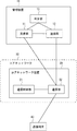
- the UE 51 may be a computer device that executes processing when a processor executes a program stored in a memory.
- the UE 51 includes a gravity / gyro sensor 71, a speed / acceleration sensor 72, a positioning device 73, a background noise sensor 74, a behavior monitoring application 75, a screen control unit 76, and a communication unit 77.
- the behavior monitoring application 75, the screen control unit 76, and the communication unit 77 may be software or modules that execute processing when a processor executes a program stored in a memory.
- the screen control unit 76 and the communication unit 77 may be configured by a circuit.
- the gravity / gyro sensor 71 is, for example, a sensor that detects the tilt, vibration, rotation, etc. of the UE 51.
- the speed / acceleration sensor 72 is a sensor that detects the moving speed of the UE 51, for example.
- the positioning device 73 is a sensor that measures the position of the UE 51 using, for example, GPS.
- the background noise sensor 74 is a sensor that detects sound flowing around the UE 51, for example.
- the gravity / gyro sensor 71, the speed / acceleration sensor 72, the positioning device 73, and the background noise sensor 74 output the detected sensor information to the behavior monitoring application 75.
- the behavior monitoring application 75 analyzes the received sensor information and identifies the behavior of the UE 51. For example, the behavior monitoring application 75 may analyze whether the vibration is detected during walking or the vibration detected when riding a bicycle using the information output from the gravity / gyro sensor 71. Furthermore, the behavior monitoring application 75 uses the information related to the moving speed output from the speed / acceleration sensor 72 and the information related to vibration output from the gravity / gyro sensor 71 to cause the user holding the UE 51 to walk. You may specify whether you are riding or riding a bicycle.
- the behavior monitoring application 75 may analyze information related to the sound output from the background noise sensor 74 and estimate the situation around the UE 51. For example, if the voice output from the background noise sensor 74 includes an announcement of the station name on a regular basis, the user holding the UE 51 may estimate that the user is moving by train.
- the behavior monitoring application 75 transmits the analyzed information or sensor information output from various sensors to the management server 15 via the communication unit 77.
- the screen control unit 76 displays a warning message on the screen of the UE 51 when it is necessary to notify the user holding the UE 51 of the suspension of use of the UE 51 or the like in the analysis result of the behavior monitoring application 75.
- the communication unit 77 performs data transmission / reception by performing wireless communication with the eNB 52.
- the communication unit 77 transmits analysis information, sensor information, or the like output from the behavior monitoring application 75 to the management server 15 via EPS.
- the communication unit 77 may perform wireless communication with the eNB 52 using LTE as a communication method.
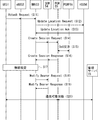
- the UE 51 transmits an Attach Request message to the MME 53 via the eNB 52 when the power is changed to the ON state or the like (S11).
- the MME 53 transmits an Update Location Request message to the HSS 56 in order to acquire subscriber information regarding the UE 51 (S12).
- the HSS 56 transmits an Update Location Ack message to the MME 53 as a response to the Update Location Request message (S13).
- the HSS 56 sets APN (Access Point Name) information connectable to the management server 15 in the Update Location Ack message.
- the MME 53 selects the SGW 54 and the PGW 55 that relay user data related to the UE 51, and transmits a Create Session Request message to the SGW 54 (S14). Further, the SGW 54 transmits the received Create Session Request message to the PGW 55 (S14).
- the PGW 55 performs a QoS (Quality of Service) setting process applied to data transmission related to the UE 51 with the PCRF 58 (S15).
- the PGW 55 performs a negotiation process with the PCRF 58 for determining a QoS value to be applied in data transmission related to the UE 51.
- the PGW 55 sends a Create Session Response message to the SGW 54 as a response to the Create Session Request message (S16). Further, the SGW 54 transmits the received Create Session Response message to the MME 53 (S16).
- the MME 53, the eNB 52, and the UE 51 perform a wireless setting process between the UE 51 and the eNB 52 (S17).
- the MME 53 may notify the UE 51 of APN information connectable to the management server 15 received in step S13 in the wireless setting process in step S17.
- the MME 53 transmits a ModifyMEBearer Request message to the SGW 54 (S18).
- the SGW 54 transmits a Modify Bearer Response message to the MME 53 as a response to the Modify Bearer Request message (S19).
- a route or tunnel for transmitting / receiving user data is set between the UE 51 and the PGW 55. Therefore, UE51 will be in the state which can communicate with the management server 15 via PGW55 (S20). For example, the UE 51 can transmit analysis information or sensor information generated by the behavior monitoring application 75 to the management server 15 via the EPS after the processing of steps S11 to S19 is executed.
- FIG. 4 the flow of the Attach process for enabling the UE 51 to communicate with the management server 15 has been described, but the UE 51 similarly performs the process for enabling IMS or Internet communication or the like. It's okay.
- the UE 51 may perform an Attach process for enabling communication with the management server 15 as shown in FIG.
- the management server 15 transmits a Monitoring Request message to the SCEF 57 in order to request the EPS to monitor whether or not the UE 51 is walking (S31).
- the SCEF 57 transmits, as the monitoring contents of the UE 51, for example, a Submit Request message instructing to monitor the change of the location information of the UE 51 to the MME 53 (S32).
- the SCEF 57 may transmit a Submit Request message to the MME 53 via the HSS 56.
- the SCEF 57 transmits a Monitoring Response message to the management server 15 as a response to the Monitoring Request message (S33).
- the MME 53 transmits a Submit Response message to the SCEF 57 as a response to the Submit Request message (S34).
- the MME 53 starts event measurement related to the UE 51 (S35).
- the event measurement may be, for example, monitoring whether the UE 51 is moving.
- the movement of the UE 51 may be detected by the MME 53 detecting a change in Global Cell ID where the UE 51 is located, a change in TA (Tracking Area), a change in RA (Routing Area), or the like. That is, by starting event measurement in step S35, the MME 53 monitors whether or not the position of the UE 51 has changed.
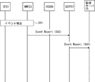
- the MME 53 detects an event that the UE 51 has moved due to a change in Global Cell ID, a change in TA, a change in RA, or the like (S41).
- the MME 53 transmits an Event-Report message in which the detection result of the event is set to the SCEF 57 (S42).
- the MME 53 may transmit the Event Report message to the SCEF 57 via the HSS 56.
- the SCEF 57 transmits the Event Report message transmitted from the MME 53 to the management server 15 (S43).
- the management server 15 uses the detection result of the event transmitted from the SCEF 57, and the analysis result of the sensor information transmitted from the UE 51 after the communication with the UE 51 is enabled in step S20 of FIG. Then, it is determined to stop communication related to the UE 51 (S51).
- the management server 15 indicates that the user is walking in the analysis result of the sensor information transmitted from the UE 51 and the movement of the UE 51 is also confirmed in the detection result of the event transmitted from the SCEF 57, It may be determined that the user holding the UE 51 is walking, and the communication regarding the UE 51 is to be suspended (Suspend).
- the management server 15 confirms the movement of the UE 51 in the event detection result transmitted from the SCEF 57
- the analysis result of the sensor information transmitted from the UE 51 indicates that the UE 51 is moving by train.
- the communication regarding the UE 51 may be determined to be continued.
- the management server 15 transmits to the SCEF 57 a Suspend Request message instructing to stop communication related to the UE 51 (S52).
- the management server 15 may determine communication to be stopped for each APN to which the UE 51 is connected, or determine communication to be stopped for each service flow identified by the source and destination IP addresses or port numbers. Also good.
- the management server 15 sets the APN or service flow for which communication is to be stopped in the Suspend Request message (S52).
- the management server 15 may not stop the communication, and may stop the communication when the external service network 62 is specified as the APN. That is, the user may be excluded from the communication suspension target in the voice communication that can secure the field of view.
- the management server 15 may determine whether to permit communication related to the UE 51 according to the time zone. For example, the management server 15 may decide to suspend communication related to the UE 51 at 9:00 to 12:00 and 13:00 to 17:00 corresponding to the user's work time or class time. In addition, the management server 15 may combine a plurality of determination criteria as to whether to stop communication related to the UE 51.
- the SCEF 57 transmits to the PCRF 58 a Suspend Request message in which an APN or service flow for which communication is to be stopped is set (S53).
- the SCEF 57 may transmit a Suspend Request message to the plurality of PCRFs 58.
- the PCRF 58 transmits to the PGW 55 a PCC rule provisioning message in which the APN or service flow that is the target of communication stop set in the received Suspend Request message is set (S54).
- the PCRF 58 may transmit a PCC rule provisioning message to the plurality of PGWs 55 when there are a plurality of PGWs 55 that control the APNs to which communication is to be stopped.
- the PGW 55 transmits an Ack message to the PCRF 58 as a response to the PCC rule provisioning message (S55).
- the PCRF 58 transmits a Response message to the SCEF 57 as a response to the Suspend Request message (S56).
- the SCEF 57 transmits a Response message to the management server 15 as a response to the Suspend Request message (S57).
- the PGW 55 stops communication corresponding to the APN or service flow that is the target of communication stop set in the PCC rule provisioning message received in step S54.
- FIG. 7 illustrates an example in which the management server 15 transmits a Suspend request message to the SCEF 57 after stopping communication related to the UE 51.
- the management server 15 relates to the UE 51 stopped in step S51. You may decide to resume communication (Resume).
- the management server 15 transmits a Resume request message to the SCEF 57, and the SCEF 57 also transmits a Resume request request to the PCRF 58.
- a QoS Request message defined in 3GPP may be used.
- the management server 15 restricts the communication, that is, the communication is stopped.
- the UE 51 may be notified of information including whether it has been resumed or resumed.
- the user holding the UE 51 can check the communication restriction state through a screen warning message performed by the screen control unit 76 based on information notified from the management server 15 to the UE 51.
- FIG. 8 shows the flow of processing when the management server 15 stops a specific service related to the UE 51.
- the specific service is, for example, a voice service in which call processing is controlled by IMS.
- the AF (Application Function) server in FIG. 8 is assumed to be a server constituting the IMS.
- Steps S61 to S63 are the same as steps S51 to S53 in FIG. In steps S62 and S63, it is assumed that IMS is designated as the APN that is the target of communication stop.
- the PCRF 58 When the PCRF 58 receives the Suspend request message from the SCEF 57, the PCRF 58 transmits a Suspend Notification message to the AF server that is a server constituting the IMS that is the target of communication stop (S64). Next, the AF server transmits an Ack message to the PCRF 58 as a response to the Suspend Notification message (S65). Next, the PCRF 58 transmits a Response message to the SCEF 57 as a response to the Suspend Request message (S66). Next, the SCEF 57 transmits a Response message to the management server 15 as a response to the Suspend Request message (S67).
- the AF server stops the communication targeted for communication stop set in the Suspend notification message received in step S64. For example, when the AF server decides to stop the voice communication, it notifies the caller that the UE 51 as the callee is currently moving, and selects whether or not to continue the call process. A message may be sent.
- a process of resuming communication regarding the stopped UE 51 may be executed.
- a Resume62Request message is transmitted in steps S62 and S63.
- a Resume notification message is transmitted.
- the management server 15 restricts the communication, that is, the communication is stopped.
- the UE 51 may be notified of information including whether it has been resumed or resumed.
- the user holding the UE 51 can check the communication restriction state through a screen warning message performed by the screen control unit 76 based on information notified from the management server 15 to the UE 51.
- the management server 15 uses the event information transmitted from the network defined in 3GPP and the analysis information generated in the UE 51 to walk the UE 51. It is possible to detect whether or not the communication related to the UE 51 is stopped.
- the behavior of the UE 51 can be analyzed in detail as compared with the first embodiment.
- the management server 15 can restart the UE that has stopped communication.
- control for stopping and resuming communication of the UE can be controlled by the initiative of the network side.
- Embodiment 2 although the structure of EPS (Evolved packet System) using eNB52, MME53, SGW54, and PGW55 was shown, RNC (Radio network controller) 81 shown in FIG. A network capable of accommodating a so-called third-generation radio access system such as (Serving General Packet Radio Service Support Node) 82 and GGSN (Gateway General Packet Radio Service Support Node) 83 may be used.
- EPS Evolved packet System
- MME53 Mobility Management Entity
- SGW54 Serving GPRS Support Node
- PGW55 Packet Packet Radio Service
- RNC Radio network controller
- the present invention has been described as a hardware configuration, but the present invention is not limited to this.
- the present invention executes processing in the communication terminal 40 (for example, UE 51), the management device 10 (for example, the management server 15) or the core network 30 (for example, the core network device 20), and executes a computer program on a CPU (Central Processing Unit) It is also possible to realize it.
- a CPU Central Processing Unit
- Non-transitory computer readable media include various types of tangible storage media (tangible storage medium).
- Examples of non-transitory computer-readable media include magnetic recording media (eg flexible disks, magnetic tapes, hard disk drives), magneto-optical recording media (eg magneto-optical discs), CD-ROMs (Read Only Memory), CD-Rs, CD-R / W, semiconductor memory (for example, mask ROM, PROM (Programmable ROM), EPROM (Erasable ROM), flash ROM, RAM (Random Access Memory)) are included.
- the program may also be supplied to the computer by various types of temporary computer-readable media. Examples of transitory computer readable media include electrical signals, optical signals, and electromagnetic waves.
- the temporary computer-readable medium can supply the program to the computer via a wired communication path such as an electric wire and an optical fiber, or a wireless communication path.
Abstract
Description
以下、図面を参照して本発明の実施の形態について説明する。はじめに、図1を用いて本発明の実施の形態1にかかる通信システムの構成例について説明する。図1の通信システムは、管理装置10、コアネットワーク装置20及び通信端末40を有している。コアネットワーク装置20は、コアネットワーク30内に配置されている。 (Embodiment 1)
Embodiments of the present invention will be described below with reference to the drawings. First, a configuration example of a communication system according to the first exemplary embodiment of the present invention will be described with reference to FIG. The communication system in FIG. 1 includes a
続いて、図2を用いて本発明の実施の形態2にかかる通信システムの構成例について説明する。図2の通信システムは、UE(User Equipment)51、eNB(evolved NodeB)52、MME(Mobility Management Entity)53、SGW(Serving Gateway)54、PGW(Packet Data Network Gateway)55、HSS(Home Subscriber Server)56、SCEF(Service Creation Environment Function)57、PCRF(Policy and Charging Rules Function)58及び管理サーバ15を有している。 (Embodiment 2)
Subsequently, a configuration example of the communication system according to the second exemplary embodiment of the present invention will be described with reference to FIG. 2 includes a UE (User Equipment) 51, an eNB (evolved NodeB) 52, an MME (Mobility Management Entity) 53, an SGW (Serving Gateway) 54, a PGW (Packet Data Network Gateway) 55, an HSS (Home Subscriber Server). ) 56, SCEF (Service Creation Environment Function) 57, PCRF (Policy and Charging Rules Function) 58, and
11 受信部
12 送信部
13 判定部
15 管理サーバ
20 コアネットワーク装置
21 通信制御部
22 通信部
30 コアネットワーク
40 通信端末
51 UE
52 eNB
53 MME
54 SGW
55 PGW
56 HSS
57 SCEF
58 PCRF
61 オペレータサービスネットワーク
62 外部サービスネットワーク
71 重力・ジャイロセンサ
72 速度・加速度センサ
73 測位装置
74 背景ノイズセンサ
75 挙動監視アプリケーション
76 画面制御部
77 通信部
81 RNC
82 SGSN
83 GGSN DESCRIPTION OF
52 eNB
53 MME
54 SGW
55 PGW
56 HSS
57 SCEF
58 PCRF
61
82 SGSN
83 GGSN
Claims (13)
- コアネットワーク内に配置されるコアネットワーク装置と、前記コアネットワーク装置と通信を行う管理装置とを備える通信システムであって、
前記管理装置は、
通信端末において検知されたセンサ情報を前記コアネットワークを介して受信する受信手段と、前記センサ情報が前記通信端末が移動していることを示すか否かを判定する判定手段と、前記センサ情報が前記通信端末が移動していることを示すと判定された場合、前記コアネットワーク装置へ前記通信端末に関する通信を停止することを指示する情報を送信する送信手段と、を有し、
前記コアネットワーク装置は、
前記通信端末に関する通信を停止することを指示する情報を受信すると、前記通信端末へデータを送信すること及び前記通信端末から送信されたデータを他の通信装置へ送信することを停止する通信制御手段と、を有する、通信システム。 A communication system comprising a core network device arranged in a core network and a management device for communicating with the core network device,
The management device
Receiving means for receiving sensor information detected in the communication terminal via the core network, determination means for determining whether the sensor information indicates that the communication terminal is moving, and the sensor information Transmission means for transmitting information instructing to stop communication related to the communication terminal to the core network device when it is determined that the communication terminal is moving;
The core network device is:
Communication control means for stopping transmission of data to the communication terminal and transmission of data transmitted from the communication terminal to another communication device when receiving information instructing to stop communication relating to the communication terminal And a communication system. - 前記管理装置は、
前記通信端末に関する通信を停止するか否かを判定するために用いる条件を格納する情報格納手段と、
前記センサ情報及び前記コアネットワーク装置から送信された前記通信端末の監視情報の少なくとも一方が、前記情報格納手段に格納されている条件を満たすか否かに応じて前記通信端末に関する通信を停止するか否かを判定する判定手段と、をさらに備える、請求項1に記載の通信システム。 The management device
Information storage means for storing conditions used for determining whether or not to stop communication relating to the communication terminal;
Whether to stop communication related to the communication terminal according to whether at least one of the sensor information and the monitoring information of the communication terminal transmitted from the core network device satisfies a condition stored in the information storage unit The communication system according to claim 1, further comprising determination means for determining whether or not. - 前記判定手段は、
前記通信端末に関する通信が停止している状態において、前記センサ情報及び前記コアネットワーク装置から送信された前記通信端末の監視情報が前記情報格納手段に格納されている条件を満たさない場合、前記通信端末に関する通信を再開する、請求項2に記載の通信システム。 The determination means includes
In a state where communication relating to the communication terminal is stopped, when the sensor information and the monitoring information of the communication terminal transmitted from the core network device do not satisfy the condition stored in the information storage unit, the communication terminal The communication system according to claim 2, wherein communication is resumed. - 前記判定手段は、
前記通信端末が接続するAPN(Access Point Name)単位もしくはサービスフロー単位に通信を停止するか否かを判定する、請求項2又は3のいずれか1項に記載の通信システム。 The determination means includes
The communication system according to any one of claims 2 and 3, wherein it is determined whether to stop communication in units of APN (Access Point Name) or service flows to which the communication terminal is connected. - 通信端末において検知されたセンサ情報を、コアネットワークを介して受信する受信手段と、
前記センサ情報が前記通信端末が移動していることを示す場合、前記コアネットワーク内に配置されるコアネットワーク装置であって、前記通信端末に関するデータの通信を制御する前記コアネットワーク装置へ、前記通信端末に関する通信を停止することを指示する情報を送信する送信手段と、を備える管理装置。 Receiving means for receiving sensor information detected in the communication terminal via the core network;
When the sensor information indicates that the communication terminal is moving, the communication is performed to the core network device that is arranged in the core network and controls communication of data related to the communication terminal. And a transmission unit that transmits information instructing to stop communication related to the terminal. - 前記通信端末に関する通信を停止するか否かを判定するために用いる条件を格納する情報格納手段と、
前記センサ情報及び前記コアネットワーク装置から送信された前記通信端末の監視情報の少なくとも一方が、前記情報格納手段に格納されている条件を満たすか否かに応じて前記通信端末に関する通信を停止するか否かを判定する判定手段と、をさらに備える、請求項5に記載の管理装置。 Information storage means for storing conditions used for determining whether or not to stop communication relating to the communication terminal;
Whether to stop communication related to the communication terminal according to whether at least one of the sensor information and the monitoring information of the communication terminal transmitted from the core network device satisfies a condition stored in the information storage unit The management apparatus according to claim 5, further comprising a determination unit that determines whether or not. - 前記判定手段は、
前記通信端末に関する通信が停止している状態において、前記センサ情報及び前記コアネットワーク装置から送信された前記通信端末の監視情報が前記情報格納手段に格納されている条件を満たさない場合、前記通信端末に関する通信を再開する、請求項6に記載の管理装置。 The determination means includes
In a state where communication relating to the communication terminal is stopped, when the sensor information and the monitoring information of the communication terminal transmitted from the core network device do not satisfy the condition stored in the information storage unit, the communication terminal The management apparatus according to claim 6, wherein communication regarding the communication is resumed. - 前記判定手段は、
前記通信端末が接続するAPN(Access Point Name)単位もしくはサービスフロー単位に通信を停止するか否かを判定する、請求項6又は7のいずれか1項に記載の管理装置。 The determination means includes
The management apparatus according to claim 6, wherein the management apparatus determines whether to stop communication in units of an APN (Access Point Name) or a service flow to which the communication terminal is connected. - センサ情報を用いて移動中の通信端末に関する通信を停止することを判定し、判定結果をコアネットワーク内に配置されるコアネットワーク装置であって、前記通信端末に関する通信を制御するコアネットワーク装置へ送信する管理装置に対して、自装置において検知したセンサ情報を、前記コアネットワークを介して送信する通信手段、を備える通信端末。 It is determined to stop communication related to a moving communication terminal using sensor information, and the determination result is a core network device arranged in the core network, and is transmitted to the core network device that controls communication related to the communication terminal. A communication terminal comprising communication means for transmitting sensor information detected by the own device to the managing device via the core network.
- 通信端末において検知されたセンサ情報を、コアネットワークを介して受信し、
前記センサ情報が前記通信端末が移動していることを示すか否かを判定し、
前記センサ情報が前記通信端末が移動していることを示すと判定した場合、前記コアネットワーク内に配置されるコアネットワーク装置であって、前記通信端末に関するデータの通信を制御する前記コアネットワーク装置へ、前記通信端末に関する通信を停止することを指示する情報を送信する、通信制御方法。 Receive sensor information detected in the communication terminal via the core network,
Determining whether the sensor information indicates that the communication terminal is moving;
When it is determined that the sensor information indicates that the communication terminal is moving, the core network device is disposed in the core network, and controls communication of data related to the communication terminal. A communication control method for transmitting information instructing to stop communication relating to the communication terminal. - センサ情報を用いて移動中の通信端末に関する通信を停止することを判定し、判定結果をコアネットワーク内に配置されるコアネットワーク装置であって、前記通信端末に関する通信を制御するコアネットワーク装置へ送信する管理装置に対して、自装置において検知したセンサ情報を、前記コアネットワークを介して送信する、センサ情報送信方法。 It is determined to stop communication related to a moving communication terminal using sensor information, and the determination result is a core network device arranged in the core network, and is transmitted to the core network device that controls communication related to the communication terminal. The sensor information transmission method which transmits the sensor information detected in the own apparatus with respect to the management apparatus which performs via the said core network.
- 通信端末において検知されたセンサ情報を、コアネットワークを介して受信し、
前記センサ情報が前記通信端末が移動していることを示すか否かを判定し、前記センサ情報が前記通信端末が移動していることを示すと判定した場合、前記コアネットワーク内に配置されるコアネットワーク装置であって、前記通信端末に関するデータの通信を制御する前記コアネットワーク装置へ、前記通信端末に関する通信を停止することを指示する情報を送信することをコンピュータに実行させるプログラムが格納された非一時的なコンピュータ可読媒体。 Receive sensor information detected in the communication terminal via the core network,
If the sensor information determines whether the communication terminal is moving, and if the sensor information determines that the communication terminal is moving, the sensor information is arranged in the core network A program that causes a computer to transmit information instructing to stop communication related to the communication terminal to the core network device that controls communication of data related to the communication terminal is stored. A non-transitory computer readable medium. - センサ情報を用いて移動中の通信端末に関する通信を停止することを判定し、判定結果をコアネットワーク内に配置されるコアネットワーク装置であって、前記通信端末に関する通信を制御するコアネットワーク装置へ送信する管理装置に対して、自装置において検知したセンサ情報を、前記コアネットワークを介して送信することをコンピュータに実行させるプログラムが格納された非一時的なコンピュータ可読媒体。 It is determined to stop communication related to a moving communication terminal using sensor information, and the determination result is a core network device arranged in the core network, and is transmitted to the core network device that controls communication related to the communication terminal. A non-transitory computer-readable medium storing a program that causes a computer to execute transmission of sensor information detected by itself to the management apparatus via the core network.
Priority Applications (6)
| Application Number | Priority Date | Filing Date | Title |
|---|---|---|---|
| CA2979798A CA2979798A1 (en) | 2015-03-20 | 2016-03-11 | Communication system, management apparatus, communication terminal,communication control method, sensor information transmission method, and computer readable medium |
| US15/559,629 US10863417B2 (en) | 2015-03-20 | 2016-03-11 | Communication system, management apparatus, communication terminal, communication control method, sensor information transmission method, and computer readable medium |
| JP2017507464A JPWO2016152071A1 (en) | 2015-03-20 | 2016-03-11 | Communication system, management apparatus, communication terminal, communication control method, sensor information transmission method, and program |
| KR1020227004543A KR102458117B1 (en) | 2015-03-20 | 2016-03-11 | Communication system, management device, communication terminal, communication control method, sensor information transmission method, and computer readable medium |
| EP16767980.2A EP3273723A4 (en) | 2015-03-20 | 2016-03-11 | Communication system, management device, communication terminal, communication control method, sensor information transmission method, and computer readable medium |
| KR1020177030076A KR20170129243A (en) | 2015-03-20 | 2016-03-11 | Communication system, management device, communication terminal, communication control method, sensor information transmission method, and computer readable medium |
Applications Claiming Priority (2)
| Application Number | Priority Date | Filing Date | Title |
|---|---|---|---|
| JP2015-057346 | 2015-03-20 | ||
| JP2015057346 | 2015-03-20 |
Publications (1)
| Publication Number | Publication Date |
|---|---|
| WO2016152071A1 true WO2016152071A1 (en) | 2016-09-29 |
Family
ID=56977373
Family Applications (1)
| Application Number | Title | Priority Date | Filing Date |
|---|---|---|---|
| PCT/JP2016/001403 WO2016152071A1 (en) | 2015-03-20 | 2016-03-11 | Communication system, management device, communication terminal, communication control method, sensor information transmission method, and computer readable medium |
Country Status (6)
| Country | Link |
|---|---|
| US (1) | US10863417B2 (en) |
| EP (1) | EP3273723A4 (en) |
| JP (1) | JPWO2016152071A1 (en) |
| KR (2) | KR20170129243A (en) |
| CA (1) | CA2979798A1 (en) |
| WO (1) | WO2016152071A1 (en) |
Families Citing this family (1)
| Publication number | Priority date | Publication date | Assignee | Title |
|---|---|---|---|---|
| JP5974393B2 (en) * | 2012-07-18 | 2016-08-23 | ▲ホア▼▲ウェイ▼技術有限公司Huawei Technologies Co.,Ltd. | Data connection management method, apparatus and system |
Citations (4)
| Publication number | Priority date | Publication date | Assignee | Title |
|---|---|---|---|---|
| JP2001326976A (en) * | 2000-05-17 | 2001-11-22 | Nec Corp | Incoming call regulation system and incoming call regulating method |
| JP2003018654A (en) * | 2001-07-02 | 2003-01-17 | Nec Saitama Ltd | Control method of mobile station in high-speed moving |
| JP2003298690A (en) * | 2002-04-03 | 2003-10-17 | Nec Corp | Cellular telephone set with automatic lock function |
| JP2015228575A (en) * | 2014-05-30 | 2015-12-17 | 株式会社Nttドコモ | User equipment and base station |
Family Cites Families (18)
| Publication number | Priority date | Publication date | Assignee | Title |
|---|---|---|---|---|
| GB9809632D0 (en) * | 1998-05-07 | 1998-07-01 | Jaguar Cars | Driver distraction suppression system |
| WO2001056307A2 (en) | 2000-01-25 | 2001-08-02 | Transient Wireless Technology, Inc. | Affecting communication if a mobile communication unit is likely to be traveling via a motor vehicle |
| US7116977B1 (en) * | 2000-12-19 | 2006-10-03 | Bellsouth Intellectual Property Corporation | System and method for using location information to execute an action |
| US20060252432A1 (en) * | 2005-05-09 | 2006-11-09 | Sbc Knowledge Ventures, L.P. | Method and system for enabling venues to selectively block incoming calls to cellular phones present in venue premises |
| KR101079692B1 (en) | 2005-06-13 | 2011-11-04 | 엘지전자 주식회사 | Mobile Communication Terminal and Method for Morse Signal and Analysis and conversion |
| US20090002147A1 (en) * | 2006-08-30 | 2009-01-01 | Sony Ericsson Mobile Communications Ab | Method for safe operation of mobile phone in a car environment |
| US8634788B2 (en) | 2007-03-02 | 2014-01-21 | Aegis Mobility, Inc. | System and methods for monitoring the context associated with a mobile communication device |
| US8200238B2 (en) * | 2008-06-17 | 2012-06-12 | Trimble Navigation Limited | System having doppler-based control of a mobile device |
| US8712429B2 (en) * | 2008-09-11 | 2014-04-29 | At&T Intellectual Property I, L.P. | Managing device functionality during predetermined conditions |
| US9715833B2 (en) * | 2009-03-03 | 2017-07-25 | Mobilitie, LLP | System and method for wireless communication in an educational setting |
| US8527013B2 (en) * | 2009-05-08 | 2013-09-03 | Obdedge, Llc | Systems, methods, and devices for policy-based control and monitoring of use of mobile devices by vehicle operators |
| US8666382B2 (en) | 2010-04-28 | 2014-03-04 | Tango Networks, Inc. | Controlling mobile device calls, text messages and data usage while operating a motor vehicle |
| US8676268B2 (en) * | 2010-08-25 | 2014-03-18 | Steven J. Riggs | System and method for monitoring and restricting the usage of a mobile communication device |
| US20150282009A1 (en) * | 2012-10-04 | 2015-10-01 | Nec Corporation | Radio access network apparatus, core network apparatus, mobile terminal, methods performed therein, and computer readable medium |
| US9585081B2 (en) | 2012-11-27 | 2017-02-28 | Lg Electronics Inc. | Method for connecting IMS-based service |
| KR101466763B1 (en) * | 2012-12-27 | 2014-12-09 | 세종대학교산학협력단 | Computing device in vehicle and method for carrying out wireless network communication using the same |
| US20150223053A1 (en) * | 2014-02-03 | 2015-08-06 | John Joseph Gillin, IV | Enabling Learning Access on a Mobile Device |
| US10028129B2 (en) * | 2016-09-26 | 2018-07-17 | Qualcomm Incorporated | Techniques for mobility mode selection in uplink-based and downlink-based mobility |
-
2016
- 2016-03-11 KR KR1020177030076A patent/KR20170129243A/en not_active Application Discontinuation
- 2016-03-11 WO PCT/JP2016/001403 patent/WO2016152071A1/en active Application Filing
- 2016-03-11 JP JP2017507464A patent/JPWO2016152071A1/en active Pending
- 2016-03-11 EP EP16767980.2A patent/EP3273723A4/en not_active Withdrawn
- 2016-03-11 CA CA2979798A patent/CA2979798A1/en active Pending
- 2016-03-11 KR KR1020227004543A patent/KR102458117B1/en active IP Right Grant
- 2016-03-11 US US15/559,629 patent/US10863417B2/en active Active
Patent Citations (4)
| Publication number | Priority date | Publication date | Assignee | Title |
|---|---|---|---|---|
| JP2001326976A (en) * | 2000-05-17 | 2001-11-22 | Nec Corp | Incoming call regulation system and incoming call regulating method |
| JP2003018654A (en) * | 2001-07-02 | 2003-01-17 | Nec Saitama Ltd | Control method of mobile station in high-speed moving |
| JP2003298690A (en) * | 2002-04-03 | 2003-10-17 | Nec Corp | Cellular telephone set with automatic lock function |
| JP2015228575A (en) * | 2014-05-30 | 2015-12-17 | 株式会社Nttドコモ | User equipment and base station |
Non-Patent Citations (1)
| Title |
|---|
| See also references of EP3273723A4 * |
Also Published As
| Publication number | Publication date |
|---|---|
| KR102458117B1 (en) | 2022-10-21 |
| CA2979798A1 (en) | 2016-09-29 |
| EP3273723A4 (en) | 2018-09-05 |
| JPWO2016152071A1 (en) | 2018-01-11 |
| KR20170129243A (en) | 2017-11-24 |
| KR20220025208A (en) | 2022-03-03 |
| US10863417B2 (en) | 2020-12-08 |
| EP3273723A1 (en) | 2018-01-24 |
| US20180070289A1 (en) | 2018-03-08 |
Similar Documents
| Publication | Publication Date | Title |
|---|---|---|
| JP6687136B2 (en) | First apparatus, PCRF apparatus, and methods thereof | |
| JP6370810B2 (en) | Quality of service for web client-based sessions | |
| JP6505679B2 (en) | Updating rich communication suite capability information via a communication network | |
| US9736074B2 (en) | Handling user plane congestion in a wireless communication network | |
| JP6621152B2 (en) | Bearer management apparatus and communication method | |
| JP5536910B2 (en) | System and method for managing PDP contexts in a wireless data communication network | |
| KR101585820B1 (en) | Recommending information associated with a user equipment or a communication group in a communications system | |
| US10412618B2 (en) | Optimistic quality of service set up | |
| US8504004B2 (en) | Automatic control of rate of notifications for UMTS and other simultaneous voice/data networks | |
| JP2015513864A (en) | Method for controlling services in a wireless communication system | |
| KR20160010472A (en) | Selecting an application server at which to register one or more user equipments for an internet protocol multimedia subsystem (ims) session | |
| US9609497B2 (en) | Intelligent emergency session handling | |
| US20140068098A1 (en) | Reducing network latency resulting from non-access stratum (nas) authentication for high performance content applications | |
| WO2014036324A1 (en) | Method for qos management in home and roaming scenarios based on location/app server assistance | |
| JP2016518765A (en) | Detect, report, and recover from potential service interruptions | |
| JP2017502604A (en) | Apparatus and method for avoiding data loss after inter-PDSN handoff based on simple IP network | |
| CN108370613A (en) | A kind of method and device of redirection | |
| WO2016152071A1 (en) | Communication system, management device, communication terminal, communication control method, sensor information transmission method, and computer readable medium | |
| WO2016147660A1 (en) | Management device, core network device, mobile communication terminal, communication system, determination method, and non-transitory computer-readable medium | |
| WO2016150115A1 (en) | Bearer establishment method, packet data gateway, serving gateway and system |
Legal Events
| Date | Code | Title | Description |
|---|---|---|---|
| 121 | Ep: the epo has been informed by wipo that ep was designated in this application |
Ref document number: 16767980 Country of ref document: EP Kind code of ref document: A1 |
|
| ENP | Entry into the national phase |
Ref document number: 2017507464 Country of ref document: JP Kind code of ref document: A Ref document number: 2979798 Country of ref document: CA |
|
| WWE | Wipo information: entry into national phase |
Ref document number: 15559629 Country of ref document: US |
|
| NENP | Non-entry into the national phase |
Ref country code: DE |
|
| ENP | Entry into the national phase |
Ref document number: 20177030076 Country of ref document: KR Kind code of ref document: A |