WO2016147236A1 - Illumination device - Google Patents
Illumination device Download PDFInfo
- Publication number
- WO2016147236A1 WO2016147236A1 PCT/JP2015/005978 JP2015005978W WO2016147236A1 WO 2016147236 A1 WO2016147236 A1 WO 2016147236A1 JP 2015005978 W JP2015005978 W JP 2015005978W WO 2016147236 A1 WO2016147236 A1 WO 2016147236A1
- Authority
- WO
- WIPO (PCT)
- Prior art keywords
- light
- image
- projection
- illumination
- illumination light
- Prior art date
Links
Images


Classifications
-
- F—MECHANICAL ENGINEERING; LIGHTING; HEATING; WEAPONS; BLASTING
- F21—LIGHTING
- F21S—NON-PORTABLE LIGHTING DEVICES; SYSTEMS THEREOF; VEHICLE LIGHTING DEVICES SPECIALLY ADAPTED FOR VEHICLE EXTERIORS
- F21S2/00—Systems of lighting devices, not provided for in main groups F21S4/00 - F21S10/00 or F21S19/00, e.g. of modular construction
-
- G—PHYSICS
- G03—PHOTOGRAPHY; CINEMATOGRAPHY; ANALOGOUS TECHNIQUES USING WAVES OTHER THAN OPTICAL WAVES; ELECTROGRAPHY; HOLOGRAPHY
- G03B—APPARATUS OR ARRANGEMENTS FOR TAKING PHOTOGRAPHS OR FOR PROJECTING OR VIEWING THEM; APPARATUS OR ARRANGEMENTS EMPLOYING ANALOGOUS TECHNIQUES USING WAVES OTHER THAN OPTICAL WAVES; ACCESSORIES THEREFOR
- G03B21/00—Projectors or projection-type viewers; Accessories therefor
- G03B21/14—Details
-
- H—ELECTRICITY
- H04—ELECTRIC COMMUNICATION TECHNIQUE
- H04N—PICTORIAL COMMUNICATION, e.g. TELEVISION
- H04N5/00—Details of television systems
- H04N5/74—Projection arrangements for image reproduction, e.g. using eidophor
Definitions
- the present invention relates to a lighting device.
- LEDs Light Emitting Diode
- LD Laser Diode
- Patent Literature 1 discloses an illumination device having an illumination function and a video projection function.
- an illumination device having an illumination function and a video projection function
- the present invention has been made to solve such a problem, and an object of the present invention is to provide an illuminating device that can make a lattice pattern appearing in a projection region less noticeable when illuminating light is projected.
- an aspect of an illumination device includes an illumination light / image light generation unit that generates illumination light and image light to be projected onto a predetermined projection area, and illumination that projects the illumination light.
- a projection mode switching unit that switches between a light projection mode and a video light projection mode for projecting the video light; a lens through which the illumination light and the video light pass; and a predetermined projection region by adjusting a position of the lens
- a focus adjustment unit that adjusts the focus of the illumination light and the image light with respect to the lens, and the focus adjustment unit is configured to focus the illumination light on the predetermined projection region in the illumination light projection mode. Adjust the position.
- the present invention it is possible to make the lattice pattern appearing in the projection area less noticeable when the illumination light is projected.
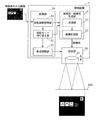
- FIG. 1 is a diagram for explaining an example of use of the illumination device according to the embodiment.
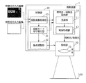
- FIG. 2 is a block diagram illustrating a configuration of the illumination device according to the embodiment.
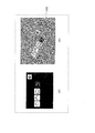
- FIG. 3A is a diagram illustrating an example of an input image for video input to the lighting device, and
- FIG. 3B is a diagram illustrating video light in a projection area based on the input image illustrated in FIG. It is a figure which shows a mode when projecting.
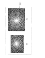
- FIG. 4A is a diagram illustrating an example of an input image for illumination input to the illumination device, and
- FIG. 4B is a diagram illustrating illumination light on a projection region based on the input image illustrated in FIG. It is a figure which shows a mode when projecting.
- FIG. 1 is a diagram for explaining an example of use of the illumination device according to the embodiment.
- FIG. 2 is a block diagram illustrating a configuration of the illumination device according to the embodiment.
- FIG. 3A is a diagram illustrating an example of an input image for video
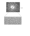
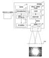
- FIG. 5 is a diagram illustrating a state when illumination light is projected by a conventional illumination device.
- FIG. 6 is a diagram for explaining the operation of the illumination apparatus according to the embodiment in the image light projection mode.
- FIG. 7 is a diagram for explaining the operation of the illumination apparatus according to the embodiment in the illumination light projection mode.
- FIG. 8 is a diagram for explaining another operation of the illumination device according to the embodiment in the illumination light projection mode.
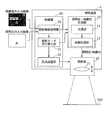
- FIG. 9 is a block diagram illustrating a configuration of a lighting device according to the first modification.
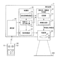
- FIG. 10 is a block diagram illustrating a configuration of a lighting device according to the second modification.
- FIG. 1 is a diagram for explaining an example of use of the illumination device according to the embodiment.
- FIG. 2 is a block diagram showing a configuration of the illumination device.
- the lighting device 1 is installed, for example, on the ceiling of a room such as a house or a store.
- the installation location of the lighting device 1 is not limited to the ceiling, but may be another part of the room such as a wall surface, or may be a structure installed in the room.
- the illuminating device 1 may be installed in places other than buildings, such as a moving body.
- the lighting device 1 selectively projects illumination light (lighting light) and video light (video light) onto a predetermined projection area 100. That is, the illumination device 1 has an illumination function that projects an illumination image as illumination light onto the projection region 100, and a video projection function that projects an image image as projection light onto the projection region 100.
- the predetermined projection area 100 means an area that has been decided in advance to project image light or illumination light from the illumination device 1 onto this area.
- the image may be either a still image or a moving image.
- One image (frame image) is composed of a plurality of picture elements arranged in a matrix. Each picture element corresponds to a pixel of a video element used in the lighting device 1.
- the picture element is a white picture element corresponding to a white pixel.
- the projection region 100 is, for example, a table, but is not limited to a table.
- the projection area 100 is not limited to a flat projection surface such as a table or a screen, but has a three-dimensional projection surface such as a sculpture or various shapes displayed on a display case such as a store.
- the product itself may be used.
- the illumination device 1 includes an illumination light / image light generation unit 10, a projection unit 20, and a control unit 30.
- the illumination light / image light generation unit 10 generates illumination light and image light for projection onto the projection region 100 and outputs the illumination light and image light to the projection unit 20. Specifically, the illumination light / video light generation unit 10 generates a projection image as illumination light and video light to be projected on the projection region 100 based on the input image acquired by the projection image acquisition unit 33.
- the frame image constituting the illumination light is an entire white image (white light)
- the frame image constituting the image light (video image) is composed of characters, figures, patterns, etc. The represented monochrome image or full-color image.
- the illumination light / image light generation unit 10 includes a light source unit 11 and an image forming unit 12.
- the light source unit 11 has a semiconductor light emitting element such as a semiconductor laser or an LED as a light source.
- the semiconductor light emitting element is driven by a driving current and emits light of a predetermined color (wavelength).
- the light source unit 11 When the illumination light and video light to be projected on the projection area 100 are full-color images, the light source unit 11 generates red light, green light, and blue light, and the illumination light and video light to be projected on the projection area 100 are monochrome images. In this case, the light source unit 11 generates white light.
- the light source of the light source unit 11 may be constituted only by a semiconductor laser, may be constituted by a combination of an excitation light source (semiconductor laser or the like) and a phosphor, or may be a white light source (semiconductor laser, Lamp) and a wavelength selection member (dichroic mirror or color filter).
- the light source unit 11 includes an arbitrary optical element such as a collimator lens that collimates the light emitted from the light source and a polarization conversion element that converts the light passing through the collimator lens. Also good.
- the image forming unit 12 forms an image to be projected on the projection region 100 from the light from the light source unit 11 and outputs the image to the projection unit 20. Specifically, the image forming unit 12 controls the light of the light source unit 11 based on the input image acquired by the projection image acquisition unit 33, and forms illumination light or video light as an image to be projected.
- the image forming unit 12 includes, for example, a video element such as a liquid crystal panel having a plurality of pixels that are partitioned by a grid-like black matrix and arranged in a matrix, and an optical element such as a lens, a mirror, and a prism.
- a video element such as a liquid crystal panel having a plurality of pixels that are partitioned by a grid-like black matrix and arranged in a matrix
- an optical element such as a lens, a mirror, and a prism.
- Each of the plurality of pixels in the video device is a red pixel, a green pixel, and a blue pixel when the image to be generated is a full color image.
- the image element is, for example, a DMD (digital mirror device).
- the DMD includes a plurality of minute mirrors associated with picture elements of the image light and illumination light.
- Each of the plurality of micromirrors is movable and basically corresponds to one picture element.
- the DMD switches whether to reflect the light from the light source unit 11 to the lens 21 by changing the angle of each micromirror. Specifically, the light from the light source unit 11 is selectively reflected toward the lens 21 by selectively rotating each micromirror. At this time, for example, when the illumination light is formed using all the picture elements, the micro mirror may be fully opened. Further, the tilt of each micromirror is controlled based on a control signal from the control unit 30.
- the image element is not limited to the reflection type image element such as DMD as long as the light distribution can be controlled, and a transmission type image element such as a liquid crystal panel may be used.
- a liquid crystal panel light modulation element
- an image (illumination light and image light) to be projected onto the projection region 100 is formed by modulating light from the light source unit 11 according to the input image.
- the liquid crystal panel may include a color filter for separating light from the light source unit 11 into red light, green light, and blue light for each pixel, a polarizing plate, and the like.
- the projection unit 20 projects the illumination light and video light generated by the illumination light / video light generation unit 10 onto the projection region 100.
- the projection unit 20 includes a lens 21 that is a projection lens.
- the illumination light and image light generated by the illumination light / image light generation unit 10 pass through the lens 21. That is, the illumination light and the image light generated by the illumination light / image light generation unit 10 are projected onto the projection region 100 by the lens 21.
- the lens 21 of the projection unit 20 may be one or plural.
- the projection unit 20 includes a convex lens as the lens 21, but may include a diaphragm, a plano-concave lens, and the like.
- the control unit 30 includes a projection mode switching unit 31, a focus adjustment unit 32, and a projection image acquisition unit 33.
- the projection mode switching unit 31 switches the projection mode of the lighting device 1. Specifically, the projection mode switching unit 31 projects an illumination light projection mode in which illumination light (projection image for illumination) is projected onto the projection area 100, and image light (projection image for video) onto the projection area 100. Selectively switch between image light projection modes.
- the illumination device 1 projects image light in the image light projection mode, and projects illumination light in the illumination light projection mode.
- the control unit 30 controls the illumination light / image light generation unit 10 so that the illumination light is output from the illumination light / image light generation unit 10.
- the control unit 30 controls the illumination light / image light generation unit 10 so that the image light is output from the illumination light / image light generation unit 10.
- the projection mode switching unit 31 switches between the illumination light projection mode and the image light projection mode based on the color change of the input image of illumination light or image light projected onto the projection region 100.
- the input image when the input image is an image for illumination, the input image does not contain information such as characters, figures, patterns, or the like, and even if it contains little information, the color change ( The differential value is considered to be small. Therefore, in the present embodiment, when the color change of the input image acquired by the projection image acquisition unit 33 is small, the control unit 30 identifies this input image as an image for illumination. Based on the identification result, the projection mode switching unit 31 switches to the illumination light projection mode so that the input image is projected as illumination light on the projection region 100.
- the control unit 30 identifies the input image as an image for video. Based on the identification result, the projection mode switching unit 31 switches to the video light projection mode so that the input image is projected as video light on the projection area 100.
- whether the color change (differential value) of the input image is large or small can be determined based on, for example, a predetermined threshold set in advance. Further, the color change (differential value) of the input image can be calculated from the change amount of the luminance signal, for example, by dividing the data signal of each pixel of the input image into the luminance signal (luminance value) and the color signal. As an example, if the change in the luminance signal in the input image is large, the input image can be identified as an image for video. If the change in the luminance signal in the input image is small, the input image is identified as an image for illumination. can do.
- the focus adjustment unit 32 adjusts the focus of the illumination light and the image light with respect to the projection region 100 by adjusting the position of the lens 21. For example, when changing the focus of illumination light and video light in the projection region 100, the focus adjustment unit 32 moves the lens 21 along the optical axis direction of the lens 21.
- the movement of the lens 21 can be realized, for example, by moving a member fixing the lens 21 with a motor or the like.
- the focus adjustment unit 32 adjusts the position of the lens 21 so that the illumination light is focused on the projection region 100 in the illumination light projection mode. That is, in the illumination light projection mode, the focus adjustment unit 32 moves the lens 21 so that the illumination light projected from the lens 21 is defocused (shifts the focus) in the projection region 100.
- the focus adjustment unit 32 adjusts the position of the lens 21 so that the image light is focused on the projection region 100 in the image light projection mode. That is, in the image light projection mode, the focus adjustment unit 32 moves the lens 21 so that the image light projected from the lens 21 is focused in the projection region 100. In this case, it is not necessary to focus completely (just focus), and it is sufficient that the projected video light (video image) is focused to such an extent that the user can visually recognize it without discomfort. That is, it is only necessary that the outline of characters, figures, etc. is projected to a certain degree without blurring the image light.
- the position of the lens 21 includes at least a first position that is a position in the illumination light projection mode and a second position that is a position in the image light projection mode.
- the focus adjustment unit 32 moves the lens 21 to the first position or the second position.
- the positions of the plurality of lenses 21 may be digitized and the numerical information may be projected onto the projection region 100 together with the illumination light.
- the projection image acquisition unit 33 acquires an image (projection image) to be projected onto the projection region 100 as an input image.
- the input image is an input image for illumination or an input image for video.
- the input image may be acquired from a recording medium such as an SD card that is detachably attached to the illumination device 1 or from an external device via a communication line such as an HDMI (registered trademark) cable connected to the illumination device 1. It may be acquired, or may be acquired from an external device using wireless communication such as Wi-Fi.
- illumination light or video light can be projected onto the projection area 100 based on an input image.
- the lighting device projects video light onto a table that is the projection region 100 as shown in FIG.
- the illumination device projects illumination light onto a table that is the projection region 100 as shown in FIG.
- the image light (image for video) is composed of a plurality of picture elements arranged in a matrix, so that the illumination light (image for illumination) is also composed of a plurality of picture elements arranged in a matrix. Will be composed.
- a user who works in an illumination environment with illumination light of the illumination device is concerned about the lattice pattern that appears in the projection area 100.
- a user who writes characters in a notebook is concerned about the lattice pattern that appears in the projection area 100. You will not be able to concentrate and work.
- a user who performs a visual task such as reading is concerned about the lattice pattern that appears in the projection region 100, and cannot perform a focused visual task. Also, the user may feel uncomfortable just by looking at the lattice pattern that should not exist in the notebook.
- this lattice pattern can be made inconspicuous by largely shifting the focus of the projection image with respect to the projection region 100. However, if the focus is always shifted, the image light is always blurred and projected when it is desired to project the image light, so that it is necessary to again adjust the focus of the image light to the projection region 100.
- the present invention has been made on the basis of such knowledge, and the inventors of the present invention control to intentionally blur the focus of the illumination light with respect to the projection region 100 when projecting the illumination light onto the projection region 100. It was found that the lattice pattern can be made inconspicuous. That is, it has been found that the focus of the projection image with respect to the projection region 100 is switched between when the image light is projected onto the projection region 100 and when the illumination light is projected.
- control is performed so that the image light is focused on the projection area 100.
- illumination light onto the projection area 100 is controlled.
- the focus is controlled to blur.
- FIG. 6 is a diagram for explaining the operation of the illumination device according to the embodiment in the image light projection mode
- FIG. 7 is a diagram for explaining the operation of the illumination device in the illumination light projection mode.
- the illumination device 1 performs control such that the image light is focused on the projection region 100 in the mode in which the image light is projected onto the projection region 100 (image light projection mode).
- the focus adjustment unit 32 adjusts the position of the lens 21 so that the image light is focused on the projection region 100. That is, the lens 21 is moved so that the image light projected from the lens 21 is focused in the projection region 100.
- the illumination device 1 performs control such that the focus of the illumination light on the projection region 100 is defocused in the mode in which the illumination light is projected onto the projection region 100 (illumination light projection mode).
- the focus adjustment unit 32 adjusts the position of the lens 21 so that the illumination light is focused on the projection region 100. That is, the lens 21 is moved so that the illumination light projected from the lens 21 is defocused in the projection region 100.
- FIG. 7 shows the case where the lens 21 is moved so that the illumination light projected from the lens 21 is under-focused in the projection region 100.
- the lens 21 may be moved so that the projected illumination light is overfocused in the projection region 100. That is, the lens 21 may be moved so that the focal point is in the far side of the projection area 100 (table).
- the focus of the illumination light with respect to the projection region 100 can be blurred. Further, in the under focus as shown in FIG. 7, when the user lifts the notebook or book, the projection region 100 moves to the front of the lighting device 1, and the illumination light approaches the just focus state, and the lattice pattern is changed. There is a possibility of being recognized. On the other hand, in overfocus as shown in FIG. 8, even when the user lifts a notebook or book and the projection area 100 moves to the front of the lighting device 1, the illumination light does not just focus. Therefore, when the focus of the illumination light on the projection region 100 is blurred in the illumination light projection mode, it is better to move the lens 21 so as to be overfocused.
- the position of the lens 21 is adjusted so that the focus of the illumination light on the projection region 100 is defocused. That is, in the image light projection mode, the position of the lens 21 is adjusted so that the image light is focused on the projection area 100, and in the illumination light projection mode, the position of the lens 21 is defocused so as to defocus the illumination light on the projection area 100. Is adjusted.
- the illumination light (illumination image) is composed of a plurality of matrix-like picture elements
- the lattice pattern between the picture elements appearing in the projection region 100 in the illumination light projection mode is conspicuous without taking time and effort. Can be difficult.
- the illumination light projection mode and the image light projection mode are switched based on the color change of the input image of the illumination light or the image light projected onto the projection area 100.
- an operation icon is projected onto the projection area 100 as video light (projected image for video).
- an icon touched by the user is recognized by an imaging camera or the like, and a function corresponding to the icon is realized. For example, using a captured image captured by an imaging camera, it is determined that the user has touched the icon when the user's finger (or its shadow) and the icon overlap, and a function corresponding to the icon is realized.
- the image light is not limited to those having a user interface function such as an icon or a keyboard, and may be a normal image such as a character, a figure, or a pattern, which is merely visual information.
- FIG. 9 is a block diagram illustrating a configuration of a lighting device according to the first modification.
- switching between the illumination light projection mode and the image light projection mode is performed by identifying whether the input image is an illumination image or a video image based on the color change of the input image.
- the input image is an image for illumination or an image for image by adding information (label) indicating that the input image is illumination light or video light in advance. And switching between the illumination light projection mode and the image light projection mode.
- the input image of illumination light includes first information (first identifier) indicating illumination light to be projected onto the projection region 100, and input of image light.
- the image has second information (second identifier) indicating that the image light is projected onto the projection area 100.
- additional information “A” is given in advance to the input image of illumination light as the first information.
- additional information “B” is given in advance to the input image of illumination light as second information.
- the first information and the second information can be added to the image as data in advance by, for example, dedicated software.
- the first information and the second information can be given to the image using editing software for recording an image on an SD card attached to the lighting device 2.
- the projection mode switching unit 31 switches between the illumination light projection mode and the video light projection mode based on the first information or the second information previously given to the input image.
- the control unit 30 detects that the first information is given to the input image acquired by the projection image acquisition unit 33, the control unit 30 identifies the input image as an image for illumination. . Based on the identification result, the projection mode switching unit 31 switches to the illumination light projection mode so that the input image is projected as illumination light on the projection region 100. In this case, the focus adjustment unit 32 adjusts the position of the lens 21 so that the illumination light is focused on the projection region 100.
- control unit 30 detects that the second information is added to the input image acquired by the projection image acquisition unit 33, the control unit 30 identifies the input image as a video image. Based on the identification result, the projection mode switching unit 31 switches to the video light projection mode so that the input image is projected as video light on the projection area 100. In this case, the focus adjustment unit 32 adjusts the position of the lens 21 so that the image light is focused on the projection region 100.
- the position of the lens 21 is adjusted so that the focus of the illumination light on the projection region 100 is defocused, as in the first embodiment.
- the lattice pattern between the picture elements appearing in the projection region 100 in the illumination light projection mode can be made inconspicuous.
- the illumination light projection mode and the image light projection mode are switched based on the first information or the second information previously given to the input image.
- FIG. 10 is a block diagram illustrating a configuration of a lighting device according to the second modification.
- the input image is identified as an illumination image or a video image and is automatically switched between the illumination light projection mode and the video light projection mode.
- switching between the illumination light projection mode and the image light projection mode is performed by receiving a switching signal from the user.
- the illuminating device 3 in the present modification further includes a communication unit 40 compared to the illuminating device 1 in the first embodiment.
- the communication unit 40 receives a switching signal for switching between the illumination light projection mode and the image light projection mode as a remote management signal from the remote controller 50 used by the user.
- the remote controller 50 is provided with a first button 51 for switching to the illumination light projection mode and a second button 52 for switching to the image light projection mode. The user presses the first button 51 or the second button 52 of the remote controller 50 when switching between the illumination light projection mode and the image light projection mode.
- the first signal for switching from the image light projection mode to the illumination light projection mode is transmitted from the remote controller 50 to the communication unit 40 of the illumination device 3 as a switching signal.
- the remote controller 50 transmits a second signal for switching from the illumination light projection mode to the video light projection mode to the communication unit 40 as a switching signal.
- the communication unit 40 outputs the received switching signal to the projection mode switching unit 31.
- the projection mode switching unit 31 switches between the illumination light projection mode and the image light projection mode in response to a switching signal (switching command) from the communication unit 40. That is, the projection mode switching unit 31 switches whether an image projected on the projection area 100 is illumination light or video light.
- the focus adjustment unit 32 adjusts the position of the lens 21 so that the focus of the illumination light on the projection area 100 is defocused.
- the focus adjustment unit 32 adjusts the position of the lens 21 so that the image light is focused on the projection area 100.
- the position of the lens 21 is adjusted so that the focus of the illumination light with respect to the projection region 100 is defocused, as in the first embodiment.
- the lattice pattern between the picture elements appearing in the projection region 100 in the illumination light projection mode can be made inconspicuous.
- the position of the lens 21 is adjusted by switching between the illumination light projection mode and the image light projection mode by the operation of the remote controller 50 by the user.
- the troublesomeness can be reduced compared with the case where the position of the lens 21 is manually adjusted. it can.
- the remote controller 50 may be configured so that the position (focus) of the lens 21 can be finely adjusted.
- the communication unit 40 may receive a signal for moving the position of the lens 21 via the remote controller 50 and transmit this signal to the focus adjustment unit 32.
- the focus adjustment unit 32 receives this signal and finely adjusts the position of the lens 21.
- the position of the lens 21 is configured to be automatically adjustable.
- the position of the lens 21 may be configured to be manually adjustable by the user. Good.
- the lens 21 is a projection lens in the projection unit 20, but is not limited to this, and can adjust the focus of illumination light and video light on the projection region 100. Any lens in the lighting device may be used. However, in order to adjust the focus with higher accuracy, the lens for adjusting the focus of the illumination light and the image light with respect to the projection region 100 is a rear stage side of the image forming unit 12 of the illumination light / image light generation unit 10. It should be a lens.
- each component in the control unit 30 may be a circuit. These circuits may constitute one circuit as a whole, or may be separate circuits. Each of these circuits may be a general-purpose circuit or a dedicated circuit.
- control unit 30 may be executed by a computer.
- a computer executes each of the above processes by executing a program using hardware resources such as a processor (CPU), a memory, and an input / output circuit.
- processor CPU
- memory such as a random access memory
- input / output circuit such as a field-programmable gate array (FPGA)
- each process is executed by the processor obtaining data to be processed from a memory or an input / output circuit or the like and calculating the data, or outputting the calculation result to the memory or the input / output circuit or the like.
Landscapes
- Physics & Mathematics (AREA)
- General Physics & Mathematics (AREA)
- Engineering & Computer Science (AREA)
- General Engineering & Computer Science (AREA)
- Multimedia (AREA)
- Signal Processing (AREA)
- Projection Apparatus (AREA)
- Transforming Electric Information Into Light Information (AREA)
- Arrangement Of Elements, Cooling, Sealing, Or The Like Of Lighting Devices (AREA)
- Non-Portable Lighting Devices Or Systems Thereof (AREA)
Abstract
The present invention is provided with: an illuminating light/video image light generation unit (10) for generating illuminating light and video image light to be projected onto a prescribed projection area; a projection mode switching unit (31) for switching between an illuminating light projection mode for projecting illuminating light and a video image light projection mode for projecting video image light; a lens (21) through which the illuminating light and video image light passes; and a focal point adjustment unit (32) for adjusting the position of the lens (21) and thereby adjusting the focal point of the illuminating light and video image light with respect to the prescribed projection area. In the illuminating light projection mode, the focal point adjustment unit (32) adjusts the position of the lens (21) so that the focal point of the illuminating light with respect to the prescribed projection area is blurred.
Description
本発明は、照明装置に関する。
The present invention relates to a lighting device.
LED(LED:Light Emitting Diode)及びレーザ(LD:Laser Diode)等の半導体発光素子は、長寿命及び省電力であることから、映像用途又は照明用途等、様々な製品の光源として期待されている。
Semiconductor light emitting devices such as LEDs (LED: Light Emitting Diode) and lasers (LD: Laser Diode) are expected to be used as light sources for various products such as video applications and lighting applications because of their long life and power saving. .
近年、プロジェクタの光源も、ランプから半導体発光素子に置き換わりつつあるために、プロジェクタの光源が長寿命化及び省電力化している。これに伴って、プロジェクタを映像投影用に用いるだけではなく、照明用に用いることも検討されている。一方、照明装置についても、照明用に用いるだけではなく、映像投影用に用いることが検討されている。例えば、特許文献1には、照明機能と映像投影機能とを有する照明装置が開示されている。
In recent years, since the light source of the projector is being replaced by a semiconductor light emitting element, the light source of the projector has a longer life and power saving. Along with this, it has been studied to use a projector not only for video projection but also for illumination. On the other hand, it is considered that the illumination device is used not only for illumination but also for video projection. For example, Patent Literature 1 discloses an illumination device having an illumination function and a video projection function.
照明機能と映像投影機能とを有する照明装置では、投影する画像を変えることで、投影領域(投影範囲)において様々な色や模様等を含む光を照射することができるので、既存の照明器具よりも多様な光の照らし方を少数の台数で実現できる。
In an illumination device having an illumination function and a video projection function, it is possible to irradiate light including various colors and patterns in the projection area (projection range) by changing the image to be projected. However, it is possible to realize various ways of illuminating light with a small number of units.
しかしながら、この種の照明装置では、マトリクス状に配列された複数の絵素で構成された映像光(映像用の画像)及び照明光(照明用の画像)を生成して投影領域に投影する。このため、照明光を投影領域に投影した際、絵素間の格子模様が投影領域に現れてしまい、格子模様が目立つという課題がある。
However, in this type of illumination device, image light (image for image) and illumination light (image for illumination) composed of a plurality of picture elements arranged in a matrix are generated and projected onto a projection area. For this reason, when the illumination light is projected onto the projection area, a lattice pattern between the picture elements appears in the projection area, and there is a problem that the lattice pattern is conspicuous.
本発明は、このような課題を解決するためになされたものであり、照明光の投影時に投影領域に現れる格子模様を目立ちにくくすることができる照明装置を提供することを目的とする。
The present invention has been made to solve such a problem, and an object of the present invention is to provide an illuminating device that can make a lattice pattern appearing in a projection region less noticeable when illuminating light is projected.
上記目的を達成するために、本発明に係る照明装置の一態様は、所定の投影領域に投射する照明光及び映像光を生成する照明光・映像光生成部と、前記照明光を投影する照明光投影モードと前記映像光を投影する映像光投影モードとを切り替える投影モード切り替え部と、前記照明光及び前記映像光が通過するレンズと、前記レンズの位置を調整することで前記所定の投影領域に対する前記照明光及び前記映像光の焦点を調整する焦点調整部とを備え、前記焦点調整部は、前記照明光投影モードにおいて、前記所定の投影領域に対する前記照明光の焦点がぼけるように前記レンズの位置を調整する。
In order to achieve the above object, an aspect of an illumination device according to the present invention includes an illumination light / image light generation unit that generates illumination light and image light to be projected onto a predetermined projection area, and illumination that projects the illumination light. A projection mode switching unit that switches between a light projection mode and a video light projection mode for projecting the video light; a lens through which the illumination light and the video light pass; and a predetermined projection region by adjusting a position of the lens A focus adjustment unit that adjusts the focus of the illumination light and the image light with respect to the lens, and the focus adjustment unit is configured to focus the illumination light on the predetermined projection region in the illumination light projection mode. Adjust the position.
本発明によれば、照明光の投影時に投影領域に現れる格子模様を目立ちにくくすることができる。
According to the present invention, it is possible to make the lattice pattern appearing in the projection area less noticeable when the illumination light is projected.
以下、本発明の実施の形態について説明する。なお、以下に説明する実施の形態は、いずれも本発明の好ましい一具体例を示すものである。したがって、以下の実施の形態で示される、数値、構成要素、構成要素の配置位置及び接続形態、並びに、ステップ及びステップの順序等は、一例であって本発明を限定する主旨ではない。よって、以下の実施の形態における構成要素のうち、本発明の最上位概念を示す独立請求項に記載されていない構成要素については、任意の構成要素として説明される。
Hereinafter, embodiments of the present invention will be described. Note that each of the embodiments described below shows a preferred specific example of the present invention. Therefore, numerical values, components, arrangement positions and connection forms of components, and steps and order of steps shown in the following embodiments are merely examples, and are not intended to limit the present invention. Therefore, among the constituent elements in the following embodiments, constituent elements that are not described in the independent claims showing the highest concept of the present invention are described as optional constituent elements.
また、各図は、模式図であり、必ずしも厳密に図示されたものではない。なお、各図において、実質的に同一の構成に対しては同一の符号を付しており、重複する説明は省略又は簡略化する。
Each figure is a schematic diagram and is not necessarily shown strictly. In each figure, substantially the same configuration is denoted by the same reference numeral, and redundant description is omitted or simplified.
(実施の形態)
[照明装置の構成]
実施の形態に係る照明装置1の構成について、図1及び図2を用いて説明する。図1は、実施の形態に係る照明装置の使用例を説明するための図である。図2は、同照明装置の構成を示すブロック図である。 (Embodiment)
[Configuration of lighting device]
The structure of theilluminating device 1 which concerns on embodiment is demonstrated using FIG.1 and FIG.2. FIG. 1 is a diagram for explaining an example of use of the illumination device according to the embodiment. FIG. 2 is a block diagram showing a configuration of the illumination device.
[照明装置の構成]
実施の形態に係る照明装置1の構成について、図1及び図2を用いて説明する。図1は、実施の形態に係る照明装置の使用例を説明するための図である。図2は、同照明装置の構成を示すブロック図である。 (Embodiment)
[Configuration of lighting device]
The structure of the
図1に示すように、照明装置1は、例えば、住宅又は店舗等の建物の室内の天井に設置される。なお、照明装置1の設置箇所は、天井に限るものでなはなく、壁面等、室内の他の部分であってもよいし、室内に設置された構造物であってもよい。また、照明装置1は、移動体等、建物以外の場所に設置されていてもよい。
As shown in FIG. 1, the lighting device 1 is installed, for example, on the ceiling of a room such as a house or a store. The installation location of the lighting device 1 is not limited to the ceiling, but may be another part of the room such as a wall surface, or may be a structure installed in the room. Moreover, the illuminating device 1 may be installed in places other than buildings, such as a moving body.
照明装置1は、所定の投影領域100に照明光(照明用の光)及び映像光(映像用の光)を選択的に投影する。つまり、照明装置1は、照明光として照明用の画像を投影領域100に投影する照明機能と、映像光として映像用の画像を投影領域100に投影する映像投影機能とを有する。ここで、所定の投影領域100とは、照明装置1からこの領域に対して映像光や照明光を投影しようと予め取り決めておいた領域を意味する。
The lighting device 1 selectively projects illumination light (lighting light) and video light (video light) onto a predetermined projection area 100. That is, the illumination device 1 has an illumination function that projects an illumination image as illumination light onto the projection region 100, and a video projection function that projects an image image as projection light onto the projection region 100. Here, the predetermined projection area 100 means an area that has been decided in advance to project image light or illumination light from the illumination device 1 onto this area.
なお、本明細書において、画像とは、静止画像及び動画像のいずれであってもよい。また、一画像(フレーム画像)は、マトリクス状に配列された複数の絵素によって構成されている。各絵素は、照明装置1に用いられる映像素子の画素に対応しており、例えば、投影する画像がモノクロ画像の場合は、白色画素に対応する白色絵素であり、また、投影する画像がフルカラー画像の場合は、赤色画素に対応する赤色絵素、緑色画素に対応する緑色絵素、及び、青色画素に対応する青色絵素である。
In this specification, the image may be either a still image or a moving image. One image (frame image) is composed of a plurality of picture elements arranged in a matrix. Each picture element corresponds to a pixel of a video element used in the lighting device 1. For example, when the image to be projected is a monochrome image, the picture element is a white picture element corresponding to a white pixel. In the case of a full color image, there are a red picture element corresponding to a red pixel, a green picture element corresponding to a green pixel, and a blue picture element corresponding to a blue pixel.
図1において、投影領域100(投影対象)は、例えばテーブルであるが、テーブルに限るものではない。また、投影領域100は、テーブルやスクリーン等のような投影面が平面的なものに限らず、彫刻等のように投影面が立体的なものや店舗等のディスプレイケースに陳列された諸々形状の商品自身等であってもよい。
In FIG. 1, the projection region 100 (projection target) is, for example, a table, but is not limited to a table. The projection area 100 is not limited to a flat projection surface such as a table or a screen, but has a three-dimensional projection surface such as a sculpture or various shapes displayed on a display case such as a store. The product itself may be used.
図2に示すように、照明装置1は、照明光・映像光生成部10と、投射部20と、制御部30とを有する。
As shown in FIG. 2, the illumination device 1 includes an illumination light / image light generation unit 10, a projection unit 20, and a control unit 30.
[照明光・映像光生成部]
照明光・映像光生成部10は、投影領域100に投影するための照明光及び映像光を生成して投射部20に出力する。具体的には、照明光・映像光生成部10は、投影画像取得部33で取得した入力画像に基づいて、投影領域100に投影すべき照明光及び映像光として投影画像を生成する。一例として、照明光(照明用の画像)を構成するフレーム画像は、全面白色画像(白色光)であり、映像光(映像用の画像)を構成するフレーム画像は、文字や図形、模様等が表されたモノクロ画像又はフルカラー画像である。 [Illumination light / image light generator]
The illumination light / imagelight generation unit 10 generates illumination light and image light for projection onto the projection region 100 and outputs the illumination light and image light to the projection unit 20. Specifically, the illumination light / video light generation unit 10 generates a projection image as illumination light and video light to be projected on the projection region 100 based on the input image acquired by the projection image acquisition unit 33. As an example, the frame image constituting the illumination light (illumination image) is an entire white image (white light), and the frame image constituting the image light (video image) is composed of characters, figures, patterns, etc. The represented monochrome image or full-color image.
照明光・映像光生成部10は、投影領域100に投影するための照明光及び映像光を生成して投射部20に出力する。具体的には、照明光・映像光生成部10は、投影画像取得部33で取得した入力画像に基づいて、投影領域100に投影すべき照明光及び映像光として投影画像を生成する。一例として、照明光(照明用の画像)を構成するフレーム画像は、全面白色画像(白色光)であり、映像光(映像用の画像)を構成するフレーム画像は、文字や図形、模様等が表されたモノクロ画像又はフルカラー画像である。 [Illumination light / image light generator]
The illumination light / image
本実施の形態において、照明光・映像光生成部10は、光源部11と、画像形成部12とを有する。
In the present embodiment, the illumination light / image light generation unit 10 includes a light source unit 11 and an image forming unit 12.
光源部11は、光源として、半導体レーザ又はLED等の半導体発光素子を有する。半導体発光素子は、駆動電流によって駆動されて所定の色(波長)の光を発する。投影領域100に投影すべき照明光及び映像光がフルカラー画像の場合、光源部11は、赤色光、緑色光及び青色光を生成し、投影領域100に投影すべき照明光及び映像光がモノクロ画像の場合、光源部11は、白色光を生成する。
The light source unit 11 has a semiconductor light emitting element such as a semiconductor laser or an LED as a light source. The semiconductor light emitting element is driven by a driving current and emits light of a predetermined color (wavelength). When the illumination light and video light to be projected on the projection area 100 are full-color images, the light source unit 11 generates red light, green light, and blue light, and the illumination light and video light to be projected on the projection area 100 are monochrome images. In this case, the light source unit 11 generates white light.
この場合、光源部11の光源は、半導体レーザのみによって構成されていてもよいし、励起光源(半導体レーザ等)と蛍光体との組み合わせによって構成されていてもよいし、白色光源(半導体レーザ、ランプ)と波長選択部材(ダイクロイックミラーやカラーフィルタ)との組み合わせによって構成されていてもよい。
In this case, the light source of the light source unit 11 may be constituted only by a semiconductor laser, may be constituted by a combination of an excitation light source (semiconductor laser or the like) and a phosphor, or may be a white light source (semiconductor laser, Lamp) and a wavelength selection member (dichroic mirror or color filter).
なお、光源部11は、光源の他に、光源から出射した光を平行化するコリメートレンズ、及び、コリメートレンズを通過する光を偏光変換する偏光変換素子等、任意の光学素子を有していてもよい。
In addition to the light source, the light source unit 11 includes an arbitrary optical element such as a collimator lens that collimates the light emitted from the light source and a polarization conversion element that converts the light passing through the collimator lens. Also good.
画像形成部12は、光源部11の光から投影領域100に投影すべき画像を形成して投射部20に出力する。具体的には、画像形成部12は、投影画像取得部33で取得した入力画像をもとに光源部11の光を制御して、投影すべき画像として照明光又は映像光を形成する。
The image forming unit 12 forms an image to be projected on the projection region 100 from the light from the light source unit 11 and outputs the image to the projection unit 20. Specifically, the image forming unit 12 controls the light of the light source unit 11 based on the input image acquired by the projection image acquisition unit 33, and forms illumination light or video light as an image to be projected.
画像形成部12は、例えば、格子状のブラックマトリクスによって区画されてマトリクス状に配列された複数の画素を有する液晶パネル等の映像素子、及び、レンズやミラー、プリズム等の光学素子等を有する。映像素子における複数の画素の各々は、生成する画像がフルカラー画像の場合は、赤色画素、緑色画素及び青色画素である。
The image forming unit 12 includes, for example, a video element such as a liquid crystal panel having a plurality of pixels that are partitioned by a grid-like black matrix and arranged in a matrix, and an optical element such as a lens, a mirror, and a prism. Each of the plurality of pixels in the video device is a red pixel, a green pixel, and a blue pixel when the image to be generated is a full color image.
映像素子は、例えば、DMD(デジタルミラーデバイス)である。DMDは、映像光及び照明光を構成する画像の絵素に対応付けられた複数の微小ミラーを備えている。複数の微小ミラーの各々は、可動式であり、基本的に一つの絵素に対応する。DMDは、各微小ミラーの角度を変更することによって、光源部11からの光をレンズ21に反射させるか否かを切り替える。具体的には、各微小ミラーを選択的に回転させることによって、光源部11からの光がレンズ21に向けて選択的に反射される。このとき、例えば全絵素を用いて照明光を形成する場合には微小ミラーをフルオープンにすればよい。また、各微小ミラーの傾きは、制御部30からの制御信号に基づいて制御される。
The image element is, for example, a DMD (digital mirror device). The DMD includes a plurality of minute mirrors associated with picture elements of the image light and illumination light. Each of the plurality of micromirrors is movable and basically corresponds to one picture element. The DMD switches whether to reflect the light from the light source unit 11 to the lens 21 by changing the angle of each micromirror. Specifically, the light from the light source unit 11 is selectively reflected toward the lens 21 by selectively rotating each micromirror. At this time, for example, when the illumination light is formed using all the picture elements, the micro mirror may be fully opened. Further, the tilt of each micromirror is controlled based on a control signal from the control unit 30.
また、映像素子としては、配光を制御できるものであれば、DMD等の反射型映像素子に限るものではなく、液晶パネル等の透過型映像素子を用いてもよい。映像素子として液晶パネル(光変調素子)を用いる場合、例えば、光源部11からの光を入力画像に応じて変調することで投影領域100に投影する画像(照明光及び映像光)を形成する。なお、液晶パネルは、光源部11からの光を画素ごとに、赤色光、緑色光及び青色光に分離するためのカラーフィルタ、及び、偏光板等を有していてもよい。
Further, the image element is not limited to the reflection type image element such as DMD as long as the light distribution can be controlled, and a transmission type image element such as a liquid crystal panel may be used. When a liquid crystal panel (light modulation element) is used as the image element, for example, an image (illumination light and image light) to be projected onto the projection region 100 is formed by modulating light from the light source unit 11 according to the input image. The liquid crystal panel may include a color filter for separating light from the light source unit 11 into red light, green light, and blue light for each pixel, a polarizing plate, and the like.
[投射部]
投射部20は、照明光・映像光生成部10で生成された照明光及び映像光を投影領域100に投射する。具体的には、投射部20は、投射レンズであるレンズ21を有する。レンズ21には、照明光・映像光生成部10で生成された照明光及び映像光が通過する。つまり、照明光・映像光生成部10で生成された照明光及び映像光は、レンズ21によって投影領域100に投射される。 [Projection section]
Theprojection unit 20 projects the illumination light and video light generated by the illumination light / video light generation unit 10 onto the projection region 100. Specifically, the projection unit 20 includes a lens 21 that is a projection lens. The illumination light and image light generated by the illumination light / image light generation unit 10 pass through the lens 21. That is, the illumination light and the image light generated by the illumination light / image light generation unit 10 are projected onto the projection region 100 by the lens 21.
投射部20は、照明光・映像光生成部10で生成された照明光及び映像光を投影領域100に投射する。具体的には、投射部20は、投射レンズであるレンズ21を有する。レンズ21には、照明光・映像光生成部10で生成された照明光及び映像光が通過する。つまり、照明光・映像光生成部10で生成された照明光及び映像光は、レンズ21によって投影領域100に投射される。 [Projection section]
The
投射部20のレンズ21は、1つであってもよいし、複数であってもよい。投射部20は、例えばレンズ21として凸レンズを有するが、これ以外に、絞り及び平凹レンズ等を有していてもよい。
The lens 21 of the projection unit 20 may be one or plural. For example, the projection unit 20 includes a convex lens as the lens 21, but may include a diaphragm, a plano-concave lens, and the like.
[制御部]
制御部30は、投影モード切り替え部31と、焦点調整部32と、投影画像取得部33とを有する。 [Control unit]
Thecontrol unit 30 includes a projection mode switching unit 31, a focus adjustment unit 32, and a projection image acquisition unit 33.
制御部30は、投影モード切り替え部31と、焦点調整部32と、投影画像取得部33とを有する。 [Control unit]
The
投影モード切り替え部31は、照明装置1の投影モードを切り替える。具体的には、投影モード切り替え部31は、投影領域100に照明光(照明用の投影画像)を投影する照明光投影モードと、投影領域100に映像光(映像用の投影画像)を投影する映像光投影モードとを選択的に切り替える。照明装置1は、映像光投影モードでは映像光を投影し、照明光投影モードでは照明光を投影する。
The projection mode switching unit 31 switches the projection mode of the lighting device 1. Specifically, the projection mode switching unit 31 projects an illumination light projection mode in which illumination light (projection image for illumination) is projected onto the projection area 100, and image light (projection image for video) onto the projection area 100. Selectively switch between image light projection modes. The illumination device 1 projects image light in the image light projection mode, and projects illumination light in the illumination light projection mode.
投影モード切り替え部31によって照明光投影モードに切り替えられた場合、制御部30は、照明光・映像光生成部10から照明光が出力されるように照明光・映像光生成部10を制御する。一方、投影モード切り替え部31によって映像光投影モードに切り替えられた場合、制御部30は、照明光・映像光生成部10から映像光が出力されるように照明光・映像光生成部10を制御する。
When the projection mode switching unit 31 switches to the illumination light projection mode, the control unit 30 controls the illumination light / image light generation unit 10 so that the illumination light is output from the illumination light / image light generation unit 10. On the other hand, when the projection mode switching unit 31 switches to the image light projection mode, the control unit 30 controls the illumination light / image light generation unit 10 so that the image light is output from the illumination light / image light generation unit 10. To do.
本実施の形態において、投影モード切り替え部31は、投影領域100に投影される照明光又は映像光の入力画像の色変化に基づいて、照明光投影モードと映像光投影モードとを切り替えている。
In the present embodiment, the projection mode switching unit 31 switches between the illumination light projection mode and the image light projection mode based on the color change of the input image of illumination light or image light projected onto the projection region 100.
具体的には、入力画像が照明用の画像である場合は、入力画像には、文字や図形、模様等の情報が含まれていないか含まれていてもわずかであるので画像の色変化(微分値)が小さいと考えられる。そこで、本実施の形態では、投影画像取得部33で取得した入力画像の色変化が小さい場合には、制御部30は、この入力画像を照明用の画像として識別する。そして、この識別結果に基づいて、投影モード切り替え部31は、投影領域100にこの入力画像が照明光として投影されるように照明光投影モードに切り替える。
Specifically, when the input image is an image for illumination, the input image does not contain information such as characters, figures, patterns, or the like, and even if it contains little information, the color change ( The differential value is considered to be small. Therefore, in the present embodiment, when the color change of the input image acquired by the projection image acquisition unit 33 is small, the control unit 30 identifies this input image as an image for illumination. Based on the identification result, the projection mode switching unit 31 switches to the illumination light projection mode so that the input image is projected as illumination light on the projection region 100.
一方、入力画像が映像用の画像である場合、入力画像には、文字や図形、模様等の情報が含まれていることが多いので画像の色変化(微分値)が大きいと考えられる。そこで、本実施の形態では、投影画像取得部33で取得した入力画像の色変化が大きい場合には、制御部30は、この入力画像を映像用の画像として識別する。そして、この識別結果に基づいて、投影モード切り替え部31は、投影領域100にこの入力画像が映像光として投影されるように映像光投影モードに切り替える。
On the other hand, when the input image is an image for video, it is considered that the color change (differential value) of the image is large because the input image often includes information such as characters, figures, and patterns. Therefore, in the present embodiment, when the color change of the input image acquired by the projection image acquisition unit 33 is large, the control unit 30 identifies the input image as an image for video. Based on the identification result, the projection mode switching unit 31 switches to the video light projection mode so that the input image is projected as video light on the projection area 100.
なお、入力画像の色変化(微分値)が大きいか小さいかは、例えば、予め設定された所定の閾値を基準に判定することができる。また、入力画像の色変化(微分値)は、例えば、入力画像の各画素のデータ信号を輝度信号(輝度値)と色信号とに分けて、輝度信号の変化量から算出することができる。一例として、入力画像における輝度信号の変化が大きい場合は、入力画像を映像用の画像として識別することができ、入力画像における輝度信号の変化が小さい場合は、入力画像を照明用の画像として識別することができる。
Note that whether the color change (differential value) of the input image is large or small can be determined based on, for example, a predetermined threshold set in advance. Further, the color change (differential value) of the input image can be calculated from the change amount of the luminance signal, for example, by dividing the data signal of each pixel of the input image into the luminance signal (luminance value) and the color signal. As an example, if the change in the luminance signal in the input image is large, the input image can be identified as an image for video. If the change in the luminance signal in the input image is small, the input image is identified as an image for illumination. can do.
焦点調整部32は、レンズ21の位置を調整することで投影領域100に対する照明光及び映像光の焦点(フォーカス)を調整する。例えば、投影領域100における照明光及び映像光の焦点を変更する場合、焦点調整部32は、レンズ21を当該レンズ21の光軸方向に沿って移動させる。レンズ21の移動は、例えば、レンズ21を固定している部材をモータ等で動かすことで実現できる。
The focus adjustment unit 32 adjusts the focus of the illumination light and the image light with respect to the projection region 100 by adjusting the position of the lens 21. For example, when changing the focus of illumination light and video light in the projection region 100, the focus adjustment unit 32 moves the lens 21 along the optical axis direction of the lens 21. The movement of the lens 21 can be realized, for example, by moving a member fixing the lens 21 with a motor or the like.
焦点調整部32は、照明光投影モードにおいて、投影領域100に対する照明光の焦点がぼけるようにレンズ21の位置を調整する。つまり、照明光投影モードでは、焦点調整部32は、レンズ21から投射される照明光が投影領域100でデフォーカスする(フォーカスをずらす)ようにレンズ21を移動させる。
The focus adjustment unit 32 adjusts the position of the lens 21 so that the illumination light is focused on the projection region 100 in the illumination light projection mode. That is, in the illumination light projection mode, the focus adjustment unit 32 moves the lens 21 so that the illumination light projected from the lens 21 is defocused (shifts the focus) in the projection region 100.
一方、焦点調整部32は、映像光投影モードにおいて、投影領域100に対する映像光の焦点が合うようにレンズ21の位置を調整する。つまり、映像光投影モードでは、焦点調整部32は、レンズ21から投射される映像光が投影領域100でフォーカスするようにレンズ21を移動させる。なお、この場合、完全にフォーカス(ジャストフォーカス)させる必要はなく、投射された映像光(映像用の画像)をユーザが不快感なく視認できる程度にフォーカスされていればよい。つまり、映像光がぼけることなく文字や図形等の輪郭がある程度くっきり投影される状態であればよい。
On the other hand, the focus adjustment unit 32 adjusts the position of the lens 21 so that the image light is focused on the projection region 100 in the image light projection mode. That is, in the image light projection mode, the focus adjustment unit 32 moves the lens 21 so that the image light projected from the lens 21 is focused in the projection region 100. In this case, it is not necessary to focus completely (just focus), and it is sufficient that the projected video light (video image) is focused to such an extent that the user can visually recognize it without discomfort. That is, it is only necessary that the outline of characters, figures, etc. is projected to a certain degree without blurring the image light.
また、本実施の形態において、レンズ21の位置には、少なくとも、照明光投影モードのときの位置である第一の位置と、映像光投影モードのときの位置である第二の位置とがあり、焦点調整部32は、レンズ21を第一の位置又は第二の位置に移動させる。なお、照明光投影モードのときのレンズ21の位置(デフォーカスの位置)は、複数であってもよい。この場合、複数のレンズ21の位置を数値化し、照明光とともに投影領域100にその数値情報を投影してもよい。
In the present embodiment, the position of the lens 21 includes at least a first position that is a position in the illumination light projection mode and a second position that is a position in the image light projection mode. The focus adjustment unit 32 moves the lens 21 to the first position or the second position. Note that there may be a plurality of positions (defocus positions) of the lens 21 in the illumination light projection mode. In this case, the positions of the plurality of lenses 21 may be digitized and the numerical information may be projected onto the projection region 100 together with the illumination light.
投影画像取得部33は、投影領域100に投影するための画像(投影画像)を入力画像として取得する。入力画像は、照明用の入力画像又は映像用の入力画像である。入力画像は、照明装置1に着脱可能に取り付けられるSDカード等の記録媒体から取得してもよいし、照明装置1に接続されたHDMI(登録商標)ケーブル等の通信線を介して外部機器から取得してもよいし、Wi-Fi等の無線通信を利用して外部機器から取得してもよい。
The projection image acquisition unit 33 acquires an image (projection image) to be projected onto the projection region 100 as an input image. The input image is an input image for illumination or an input image for video. The input image may be acquired from a recording medium such as an SD card that is detachably attached to the illumination device 1 or from an external device via a communication line such as an HDMI (registered trademark) cable connected to the illumination device 1. It may be acquired, or may be acquired from an external device using wireless communication such as Wi-Fi.
[照明装置の制御]
次に、本実施の形態に係る照明装置1の具体的な制御について、本発明に至った経緯も含めて説明する。 [Control of lighting device]
Next, specific control of thelighting device 1 according to the present embodiment will be described including the background to the present invention.
次に、本実施の形態に係る照明装置1の具体的な制御について、本発明に至った経緯も含めて説明する。 [Control of lighting device]
Next, specific control of the
照明機能と映像投影機能とを有する照明装置では、入力画像をもとに、投影領域100に照明光又は映像光を投影することができる。
In an illumination device having an illumination function and a video projection function, illumination light or video light can be projected onto the projection area 100 based on an input image.
例えば、入力画像が図3(a)に示すような映像用の画像である場合、照明装置は、図3(b)に示すように、投影領域100であるテーブルに映像光を投影する。一方、入力画像が図4(a)に示すような照明用の画像である場合、照明装置は、図4(b)に示すように、投影領域100であるテーブルに照明光を投影する。
For example, when the input image is a video image as shown in FIG. 3A, the lighting device projects video light onto a table that is the projection region 100 as shown in FIG. On the other hand, when the input image is an image for illumination as shown in FIG. 4A, the illumination device projects illumination light onto a table that is the projection region 100 as shown in FIG.
この場合、映像光(映像用の画像)は、マトリクス状に配列された複数の絵素によって構成されているので、照明光(照明用の画像)もマトリクス状に配列された複数の絵素によって構成されることになる。
In this case, the image light (image for video) is composed of a plurality of picture elements arranged in a matrix, so that the illumination light (image for illumination) is also composed of a plurality of picture elements arranged in a matrix. Will be composed.
このため、図5に示すように、これまでの照明装置では、照明光を投影領域100に投影した際に、照明機能のみを有する既存の照明器具では現れないような絵素間の格子模様が投影領域に現れてしまい、この格子模様が目立つという課題がある。
For this reason, as shown in FIG. 5, in the conventional illuminating device, when illuminating light is projected onto the projection region 100, there is a lattice pattern between picture elements that does not appear in an existing luminaire having only an illumination function. There is a problem that this lattice pattern is conspicuous because it appears in the projection area.
投影領域100に格子模様が目立って現れると、照明装置の照明光による照明環境下で作業を行うユーザは、投影領域100に現れた格子模様が気になってしまう。例えば、図5、特に、投影領域100の一部を拡大した模式的な箇所に示すように、ノートに文字を書く作業を行うユーザは、投影領域100に現れた格子模様が気になってしまい、集中して作業を行うことができなくなる。また、読書等の視作業等を行うユーザは、投影領域100に現れた格子模様が気になってしまい、集中して視作業を行うことができなくなる。また、ユーザは、そもそもノートには存在しないはずの格子模様を見ただけでも違和感を感じることもある。
When a lattice pattern appears conspicuously in the projection area 100, a user who works in an illumination environment with illumination light of the illumination device is concerned about the lattice pattern that appears in the projection area 100. For example, as shown in FIG. 5, in particular, as shown in an enlarged schematic portion of a part of the projection area 100, a user who writes characters in a notebook is concerned about the lattice pattern that appears in the projection area 100. You will not be able to concentrate and work. In addition, a user who performs a visual task such as reading is concerned about the lattice pattern that appears in the projection region 100, and cannot perform a focused visual task. Also, the user may feel uncomfortable just by looking at the lattice pattern that should not exist in the notebook.
一方、この格子模様は、投影領域100に対する投影画像の焦点を大きくずらすことで目立たなくすることができる。しかし、焦点を常にずらしておくと、映像光を投影したい場合には、映像光が常にぼけて投影されてしまうので、再度、映像光の焦点を投影領域100に合わせる手間が必要になる。
On the other hand, this lattice pattern can be made inconspicuous by largely shifting the focus of the projection image with respect to the projection region 100. However, if the focus is always shifted, the image light is always blurred and projected when it is desired to project the image light, so that it is necessary to again adjust the focus of the image light to the projection region 100.
本発明は、このような知見に基づいてなされたものであり、本願発明者らは、投影領域100に照明光を投影する際には投影領域100に対する照明光の焦点をあえてぼかすように制御することで、格子模様を目立ちにくくできることを見出した。つまり、投影領域100に映像光を投影する場合と照明光を投影する場合とで投影領域100に対する投影画像の焦点を切り替えることを見出した。
The present invention has been made on the basis of such knowledge, and the inventors of the present invention control to intentionally blur the focus of the illumination light with respect to the projection region 100 when projecting the illumination light onto the projection region 100. It was found that the lattice pattern can be made inconspicuous. That is, it has been found that the focus of the projection image with respect to the projection region 100 is switched between when the image light is projected onto the projection region 100 and when the illumination light is projected.
具体的には、投影領域100に映像光を投影する際には投影領域100に対する映像光の焦点を合わせるように制御し、投影領域100に照明光を投影する際には投影領域100に対する照明光の焦点をぼかすように制御している。
Specifically, when projecting image light onto the projection area 100, control is performed so that the image light is focused on the projection area 100. When projecting illumination light onto the projection area 100, illumination light onto the projection area 100 is controlled. The focus is controlled to blur.
以下、本実施の形態における照明装置1の具体的な制御の内容について、図6及び図7を用いて説明する。図6は、映像光投影モードにおける実施の形態に係る照明装置の動作を説明するための図であり、図7は、照明光投影モードにおける同照明装置の動作を説明するための図である。
Hereinafter, specific control contents of the lighting apparatus 1 according to the present embodiment will be described with reference to FIGS. 6 and 7. FIG. 6 is a diagram for explaining the operation of the illumination device according to the embodiment in the image light projection mode, and FIG. 7 is a diagram for explaining the operation of the illumination device in the illumination light projection mode.
図6に示すように、照明装置1は、投影領域100に映像光を投影するモード(映像光投影モード)では、投影領域100に対する映像光の焦点が合うような制御を行っている。具体的には、映像光投影モードでは、焦点調整部32によって、投影領域100に対する映像光の焦点が合うようにレンズ21の位置を調整している。つまり、レンズ21から投射される映像光が投影領域100でフォーカスするようにレンズ21を移動させている。
As shown in FIG. 6, the illumination device 1 performs control such that the image light is focused on the projection region 100 in the mode in which the image light is projected onto the projection region 100 (image light projection mode). Specifically, in the image light projection mode, the focus adjustment unit 32 adjusts the position of the lens 21 so that the image light is focused on the projection region 100. That is, the lens 21 is moved so that the image light projected from the lens 21 is focused in the projection region 100.
一方、図7に示すように、照明装置1は、投影領域100に照明光を投影するモード(照明光投影モード)では、投影領域100に対する照明光の焦点がぼけるような制御を行っている。具体的には、照明光投影モードでは、焦点調整部32によって、投影領域100に対する照明光の焦点がぼけるようにレンズ21の位置を調整している。つまり、レンズ21から投射される照明光が投影領域100でデフォーカスするようにレンズ21を移動させている。
On the other hand, as shown in FIG. 7, the illumination device 1 performs control such that the focus of the illumination light on the projection region 100 is defocused in the mode in which the illumination light is projected onto the projection region 100 (illumination light projection mode). Specifically, in the illumination light projection mode, the focus adjustment unit 32 adjusts the position of the lens 21 so that the illumination light is focused on the projection region 100. That is, the lens 21 is moved so that the illumination light projected from the lens 21 is defocused in the projection region 100.
なお、図7では、レンズ21から投射される照明光が投影領域100でアンダーフォーカスとなるようにレンズ21を移動させているが場合を示しているが、図8に示すように、レンズ21から投射される照明光が投影領域100でオーバーフォーカスとなるようにレンズ21を移動させてもよい。つまり、投影領域100(テーブル)の向こう側で焦点が合うようにレンズ21を移動させてもよい。
FIG. 7 shows the case where the lens 21 is moved so that the illumination light projected from the lens 21 is under-focused in the projection region 100. However, as shown in FIG. The lens 21 may be moved so that the projected illumination light is overfocused in the projection region 100. That is, the lens 21 may be moved so that the focal point is in the far side of the projection area 100 (table).
図8に示すような場合でも、投影領域100に対する照明光の焦点をぼけさせることができる。さらに、図7のようにアンダーフォーカスでは、ユーザがノートや本を持ち上げたときに投影領域100が照明装置1の手前に移動して、照明光がジャストフォーカス状態に近づくことになり、格子模様が認識されてしまう可能性がある。一方、図8のようにオーバーフォーカスでは、ユーザがノートや本を持ち上げて投影領域100が照明装置1の手前に移動したとしても、照明光がジャストフォーカスすることがない。したがって、照明光投影モードにおいて投影領域100に対する照明光の焦点をぼかす際は、オーバーフォーカスとなるようにレンズ21を移動させる方がよい。
Even in the case shown in FIG. 8, the focus of the illumination light with respect to the projection region 100 can be blurred. Further, in the under focus as shown in FIG. 7, when the user lifts the notebook or book, the projection region 100 moves to the front of the lighting device 1, and the illumination light approaches the just focus state, and the lattice pattern is changed. There is a possibility of being recognized. On the other hand, in overfocus as shown in FIG. 8, even when the user lifts a notebook or book and the projection area 100 moves to the front of the lighting device 1, the illumination light does not just focus. Therefore, when the focus of the illumination light on the projection region 100 is blurred in the illumination light projection mode, it is better to move the lens 21 so as to be overfocused.
[まとめ]
以上、本実施の形態における照明装置1では、照明光投影モードにおいては、投影領域100に対する照明光の焦点がぼけるようにレンズ21の位置を調整している。すなわち、映像光投影モードにおいては投影領域100に対する映像光の焦点を合わせるようにレンズ21の位置を調整し、照明光投影モードにおいては投影領域100に対する照明光の焦点をぼかすようにレンズ21の位置を調整している。 [Summary]
As described above, in theillumination device 1 according to the present embodiment, in the illumination light projection mode, the position of the lens 21 is adjusted so that the focus of the illumination light on the projection region 100 is defocused. That is, in the image light projection mode, the position of the lens 21 is adjusted so that the image light is focused on the projection area 100, and in the illumination light projection mode, the position of the lens 21 is defocused so as to defocus the illumination light on the projection area 100. Is adjusted.
以上、本実施の形態における照明装置1では、照明光投影モードにおいては、投影領域100に対する照明光の焦点がぼけるようにレンズ21の位置を調整している。すなわち、映像光投影モードにおいては投影領域100に対する映像光の焦点を合わせるようにレンズ21の位置を調整し、照明光投影モードにおいては投影領域100に対する照明光の焦点をぼかすようにレンズ21の位置を調整している。 [Summary]
As described above, in the
これにより、照明光(照明用の画像)がマトリクス状の複数の絵素で構成されていても、手間をかけることなく、照明光投影モードにおいて投影領域100に現れる絵素間の格子模様を目立ちにくくすることができる。
Thus, even if the illumination light (illumination image) is composed of a plurality of matrix-like picture elements, the lattice pattern between the picture elements appearing in the projection region 100 in the illumination light projection mode is conspicuous without taking time and effort. Can be difficult.
また、本実施の形態では、投影領域100に投影する照明光又は映像光の入力画像の色変化に基づいて、照明光投影モードと映像光投影モードとを切り替えている。
In this embodiment, the illumination light projection mode and the image light projection mode are switched based on the color change of the input image of the illumination light or the image light projected onto the projection area 100.
これにより、入力画像が照明用の画像であるか映像用の画像であるかを自動で識別できるので、照明光投影モードと映像光投影モードとの切り替えを自動に行うことができる。したがって、照明光投影モードと映像光投影モードとの切り替えの煩わしさをなくすことができる。
This makes it possible to automatically identify whether the input image is an illumination image or a video image, so that it is possible to automatically switch between the illumination light projection mode and the video light projection mode. Therefore, the troublesomeness of switching between the illumination light projection mode and the image light projection mode can be eliminated.
なお、本実施の形態において、投影領域100には、図3の(a)及び(b)に示すように、映像光(映像用の投影画像)として操作用のアイコンを投影している。この場合、ユーザが触れたアイコンを撮像カメラ等で認識し、当該アイコンに対応する機能を実現する。例えば、撮像カメラで撮像した撮像画像を用いて、ユーザの指(又はその影)とアイコンとが重なったときにユーザがアイコンを触ったと判定し、そのアイコンに対応する機能を実現する。
In the present embodiment, as shown in FIGS. 3A and 3B, an operation icon is projected onto the projection area 100 as video light (projected image for video). In this case, an icon touched by the user is recognized by an imaging camera or the like, and a function corresponding to the icon is realized. For example, using a captured image captured by an imaging camera, it is determined that the user has touched the icon when the user's finger (or its shadow) and the icon overlap, and a function corresponding to the icon is realized.
また、映像光は、アイコンやキーボード等のユーザインターフェース機能を有するものに限るものではなく、視覚的な情報にすぎない、文字や図形、模様等の通常の画像であってもよい。
Further, the image light is not limited to those having a user interface function such as an icon or a keyboard, and may be a normal image such as a character, a figure, or a pattern, which is merely visual information.
(変形例1)
次に、変形例1に係る照明装置2について、図9を用いて説明する。図9は、変形例1に係る照明装置の構成を示すブロック図である。 (Modification 1)
Next, the illuminatingdevice 2 which concerns on the modification 1 is demonstrated using FIG. FIG. 9 is a block diagram illustrating a configuration of a lighting device according to the first modification.
次に、変形例1に係る照明装置2について、図9を用いて説明する。図9は、変形例1に係る照明装置の構成を示すブロック図である。 (Modification 1)
Next, the illuminating
上記実施の形態では、入力画像の色変化に基づいて入力画像が照明用の画像であるか映像用の画像であるかを識別して照明光投影モードと映像光投影モードとの切り替えを行ったが、本変形例では、入力画像に予めの照明光又は映像光であることを示す情報(ラベル)を付与しておくことで、入力画像が照明用の画像であるか映像用の画像であるかを識別して照明光投影モードと映像光投影モードとの切り替えを行う。
In the above-described embodiment, switching between the illumination light projection mode and the image light projection mode is performed by identifying whether the input image is an illumination image or a video image based on the color change of the input image. However, in this modification, the input image is an image for illumination or an image for image by adding information (label) indicating that the input image is illumination light or video light in advance. And switching between the illumination light projection mode and the image light projection mode.
具体的には、図9に示すように、照明光の入力画像は、投影領域100に投影する照明光であることを示す第一情報(第一識別子)を有しており、映像光の入力画像は、投影領域100に投影する映像光であることを示す第二情報(第二識別子)を有している。
Specifically, as illustrated in FIG. 9, the input image of illumination light includes first information (first identifier) indicating illumination light to be projected onto the projection region 100, and input of image light. The image has second information (second identifier) indicating that the image light is projected onto the projection area 100.
例えば、照明光の入力画像には、第一情報として「A」という付加情報が予め付与されている。また、照明光の入力画像には、第二情報として「B」という付加情報が予め付与されている。
For example, additional information “A” is given in advance to the input image of illumination light as the first information. Further, additional information “B” is given in advance to the input image of illumination light as second information.
第一情報及び第二情報は、例えば専用ソフトによって予めで画像にデータとして付与しておくことができる。例えば、照明装置2に装着するSDカードに画像を記録させる際の編集ソフトを用いて、当該画像に第一情報及び第二情報を付与することができる。
The first information and the second information can be added to the image as data in advance by, for example, dedicated software. For example, the first information and the second information can be given to the image using editing software for recording an image on an SD card attached to the lighting device 2.
そして、本変形例においては、投影モード切り替え部31は、入力画像に予め付与された第一情報又は第二情報に基づいて、照明光投影モードと映像光投影モードとを切り替える。
In the present modification, the projection mode switching unit 31 switches between the illumination light projection mode and the video light projection mode based on the first information or the second information previously given to the input image.
具体的には、投影画像取得部33で取得した入力画像に第一情報が付与されていることを制御部30が検知した場合、制御部30は、この入力画像を照明用の画像として識別する。そして、この識別結果に基づいて、投影モード切り替え部31は、投影領域100にこの入力画像が照明光として投影されるように照明光投影モードに切り替える。この場合、焦点調整部32は、投影領域100に対する照明光の焦点がぼけるようにレンズ21の位置を調整する。
Specifically, when the control unit 30 detects that the first information is given to the input image acquired by the projection image acquisition unit 33, the control unit 30 identifies the input image as an image for illumination. . Based on the identification result, the projection mode switching unit 31 switches to the illumination light projection mode so that the input image is projected as illumination light on the projection region 100. In this case, the focus adjustment unit 32 adjusts the position of the lens 21 so that the illumination light is focused on the projection region 100.
一方、投影画像取得部33で取得した入力画像に第二情報が付与されていることを制御部30が検知した場合、制御部30は、この入力画像を映像用の画像として識別する。そして、この識別結果に基づいて、投影モード切り替え部31は、投影領域100にこの入力画像が映像光として投影されるように映像光投影モードに切り替える。この場合、焦点調整部32は、投影領域100に対する映像光の焦点が合うようにレンズ21の位置を調整する。
On the other hand, when the control unit 30 detects that the second information is added to the input image acquired by the projection image acquisition unit 33, the control unit 30 identifies the input image as a video image. Based on the identification result, the projection mode switching unit 31 switches to the video light projection mode so that the input image is projected as video light on the projection area 100. In this case, the focus adjustment unit 32 adjusts the position of the lens 21 so that the image light is focused on the projection region 100.
以上、本変形例における照明装置2によれば、実施の形態1と同様に、照明光投影モードにおいては、投影領域100に対する照明光の焦点がぼけるようにレンズ21の位置を調整している。
As described above, according to the illumination device 2 in the present modification, in the illumination light projection mode, the position of the lens 21 is adjusted so that the focus of the illumination light on the projection region 100 is defocused, as in the first embodiment.
これにより、照明光投影モードにおいて投影領域100に現れる絵素間の格子模様を目立ちにくくすることができる。
Thereby, the lattice pattern between the picture elements appearing in the projection region 100 in the illumination light projection mode can be made inconspicuous.
また、本変形例では、入力画像に予め付与された第一情報又は第二情報に基づいて、照明光投影モードと映像光投影モードとを切り替えている。
In this modification, the illumination light projection mode and the image light projection mode are switched based on the first information or the second information previously given to the input image.
これにより、入力画像が照明用の画像であるか映像用の画像であるかを自動で識別できるので、照明光投影モードと映像光投影モードとの切り替えを自動で行うことができる。したがって、照明光投影モードと映像光投影モードとの切り替えの煩わしさをなくすことができる。
This makes it possible to automatically identify whether the input image is an illumination image or a video image, so that the illumination light projection mode and the video light projection mode can be switched automatically. Therefore, the troublesomeness of switching between the illumination light projection mode and the image light projection mode can be eliminated.
(変形例2)
次に、変形例2に係る照明装置3について、図10を用いて説明する。図10は、変形例2に係る照明装置の構成を示すブロック図である。 (Modification 2)
Next, the illuminatingdevice 3 which concerns on the modification 2 is demonstrated using FIG. FIG. 10 is a block diagram illustrating a configuration of a lighting device according to the second modification.
次に、変形例2に係る照明装置3について、図10を用いて説明する。図10は、変形例2に係る照明装置の構成を示すブロック図である。 (Modification 2)
Next, the illuminating
上記実施の形態及び変形例1では、入力画像が照明用の画像であるか映像用の画像であるかを識別して自動的に照明光投影モードと映像光投影モードとの切り替えを行ったが、本変形例では、ユーザからの切り替え信号を受信することで照明光投影モードと映像光投影モードとの切り替えを行う。
In the above embodiment and the first modification, the input image is identified as an illumination image or a video image and is automatically switched between the illumination light projection mode and the video light projection mode. In this modification, switching between the illumination light projection mode and the image light projection mode is performed by receiving a switching signal from the user.
具体的には、本変形例における照明装置3は、実施の形態1における照明装置1に対して、さらに、通信部40を備える。
Specifically, the illuminating device 3 in the present modification further includes a communication unit 40 compared to the illuminating device 1 in the first embodiment.
通信部40は、ユーザが使用するリモコン50から、遠隔管理信号として、照明光投影モードと映像光投影モードとを切り替える切り替え信号を受信する。例えば、リモコン50には照明光投影モードに切り替えるための第一ボタン51と映像光投影モードに切り替えるための第二ボタン52とが設けられている。ユーザは、照明光投影モードと映像光投影モードとを切り替えたい場合に、リモコン50の第一ボタン51又は第二ボタン52を押下する。
The communication unit 40 receives a switching signal for switching between the illumination light projection mode and the image light projection mode as a remote management signal from the remote controller 50 used by the user. For example, the remote controller 50 is provided with a first button 51 for switching to the illumination light projection mode and a second button 52 for switching to the image light projection mode. The user presses the first button 51 or the second button 52 of the remote controller 50 when switching between the illumination light projection mode and the image light projection mode.
ユーザがリモコン50の第一ボタン51を押下すると、リモコン50からは、切り替え信号として、映像光投影モードから照明光投影モードに切り替えるための第一信号が照明装置3の通信部40に送信される。一方、ユーザがリモコン50の第二ボタン52を押下すると、リモコン50からは、切り替え信号として、照明光投影モードから映像光投影モードに切り替えるための第二信号が通信部40に送信される。
When the user presses the first button 51 of the remote controller 50, the first signal for switching from the image light projection mode to the illumination light projection mode is transmitted from the remote controller 50 to the communication unit 40 of the illumination device 3 as a switching signal. . On the other hand, when the user presses the second button 52 of the remote controller 50, the remote controller 50 transmits a second signal for switching from the illumination light projection mode to the video light projection mode to the communication unit 40 as a switching signal.
通信部40は、受信した切り替え信号を投影モード切り替え部31に出力する。投影モード切り替え部31は、通信部40からの切り替え信号(切り替え命令)に応じて、照明光投影モードと映像光投影モードとの切り替えを行う。つまり、投影モード切り替え部31は、投影領域100に投影する画像を照明光とするか映像光とするかを切り替える。
The communication unit 40 outputs the received switching signal to the projection mode switching unit 31. The projection mode switching unit 31 switches between the illumination light projection mode and the image light projection mode in response to a switching signal (switching command) from the communication unit 40. That is, the projection mode switching unit 31 switches whether an image projected on the projection area 100 is illumination light or video light.
そして、投影領域100に照明光を投影する場合、焦点調整部32は、投影領域100に対する照明光の焦点がぼけるようにレンズ21の位置を調整する。一方、投影領域100に映像光を投影する場合、焦点調整部32は、投影領域100に対する映像光の焦点が合うようにレンズ21の位置を調整する。
Then, when projecting illumination light onto the projection area 100, the focus adjustment unit 32 adjusts the position of the lens 21 so that the focus of the illumination light on the projection area 100 is defocused. On the other hand, when projecting image light onto the projection area 100, the focus adjustment unit 32 adjusts the position of the lens 21 so that the image light is focused on the projection area 100.
以上、本変形例における照明装置3によれば、実施の形態1と同様に、照明光投影モードにおいては、投影領域100に対する照明光の焦点がぼけるようにレンズ21の位置を調整している。
As described above, according to the illumination device 3 in the present modification, in the illumination light projection mode, the position of the lens 21 is adjusted so that the focus of the illumination light with respect to the projection region 100 is defocused, as in the first embodiment.
これにより、照明光投影モードにおいて投影領域100に現れる絵素間の格子模様を目立ちにくくすることができる。
Thereby, the lattice pattern between the picture elements appearing in the projection region 100 in the illumination light projection mode can be made inconspicuous.
また、本変形例では、ユーザによるリモコン50の操作で照明光投影モードと映像光投影モードとを切り替えることによってレンズ21の位置を調整している。
Further, in this modification, the position of the lens 21 is adjusted by switching between the illumination light projection mode and the image light projection mode by the operation of the remote controller 50 by the user.
これにより、ユーザはリモコン50のボタンを押すだけで照明光投影モードと映像光投影モードとを切り替えることができるので、手動でレンズ21を位置を調整する場合と比べて煩わしさを軽減することができる。
Accordingly, since the user can switch between the illumination light projection mode and the image light projection mode only by pressing a button on the remote controller 50, the troublesomeness can be reduced compared with the case where the position of the lens 21 is manually adjusted. it can.
なお、本変形例において、リモコン50によってレンズ21の位置(フォーカス)を微調整できるように構成されていてもよい。例えば、通信部40は、リモコン50を介してレンズ21の位置を移動させるための信号を受信して、この信号を焦点調整部32に送信してもよい。焦点調整部32は、この信号を受けてレンズ21の位置を微調整する。
In this modification, the remote controller 50 may be configured so that the position (focus) of the lens 21 can be finely adjusted. For example, the communication unit 40 may receive a signal for moving the position of the lens 21 via the remote controller 50 and transmit this signal to the focus adjustment unit 32. The focus adjustment unit 32 receives this signal and finely adjusts the position of the lens 21.
(その他変形例等)
以上、本発明に係る照明装置について、実施の形態及び変形例に基づいて説明したが、本発明は、上記の実施の形態及び変形例に限定されるものではない。 (Other variations)
The lighting device according to the present invention has been described above based on the embodiments and the modifications. However, the present invention is not limited to the above-described embodiments and modifications.
例えば、上記の実施の形態及び変形例1、2では、レンズ21の位置は自動で調整できるように構成されていたが、レンズ21の位置はユーザが手動でも調整できるように構成されていてもよい。
For example, in the above-described embodiment and Modifications 1 and 2, the position of the lens 21 is configured to be automatically adjustable. However, the position of the lens 21 may be configured to be manually adjustable by the user. Good.
また、上記の実施の形態及び変形例1、2において、レンズ21は投射部20における投射レンズとしたが、これに限るものではなく、投影領域100に対する照明光及び映像光の焦点を調整できるものであれば、照明装置内のいずれのレンズであってもよい。ただし、より精度よく焦点を調整するために、投影領域100に対する照明光及び映像光の焦点を調整するためのレンズとしては、照明光・映像光生成部10の画像形成部12よりも後段側のレンズであるとよい。
In the above-described embodiment and Modifications 1 and 2, the lens 21 is a projection lens in the projection unit 20, but is not limited to this, and can adjust the focus of illumination light and video light on the projection region 100. Any lens in the lighting device may be used. However, in order to adjust the focus with higher accuracy, the lens for adjusting the focus of the illumination light and the image light with respect to the projection region 100 is a rear stage side of the image forming unit 12 of the illumination light / image light generation unit 10. It should be a lens.
その他、上記の実施の形態に対して当業者が思いつく各種変形を施して得られる形態、又は、本発明の趣旨を逸脱しない範囲で上記の実施の形態における構成要素及び機能を任意に組み合わせることで実現される形態も本発明に含まれる。
In addition, a form obtained by making various modifications conceived by those skilled in the art to the above-described embodiment, or by arbitrarily combining the components and functions in the above-described embodiment without departing from the gist of the present invention. Implemented forms are also included in the present invention.
また、上記の説明において、制御部30における各構成は、回路であってもよい。これらの回路は、全体として1つの回路を構成してもよいし、それぞれ別々の回路でもよい。また、これらの回路は、それぞれ、汎用的な回路でもよいし、専用の回路でもよい。
In the above description, each component in the control unit 30 may be a circuit. These circuits may constitute one circuit as a whole, or may be separate circuits. Each of these circuits may be a general-purpose circuit or a dedicated circuit.
また、上記の制御部30の動作として説明した処理は、コンピュータが実行してもよい。例えば、コンピュータが、プロセッサ(CPU)、メモリ及び入出力回路等のハードウェア資源を用いてプログラムを実行することによって、上記の各処理を実行する。具体的には、プロセッサが処理対象のデータをメモリ又は入出力回路等から取得してデータを演算したり、演算結果をメモリ又は入出力回路等に出力したりすることによって、各処理を実行する。
Further, the processing described as the operation of the control unit 30 may be executed by a computer. For example, a computer executes each of the above processes by executing a program using hardware resources such as a processor (CPU), a memory, and an input / output circuit. Specifically, each process is executed by the processor obtaining data to be processed from a memory or an input / output circuit or the like and calculating the data, or outputting the calculation result to the memory or the input / output circuit or the like. .
1、2、3 照明装置
10 照明光・映像光生成部
21 レンズ
31 投影モード切り替え部
32 焦点調整部 1, 2, 3Illumination device 10 Illumination light / video light generation unit 21 Lens 31 Projection mode switching unit 32 Focus adjustment unit
10 照明光・映像光生成部
21 レンズ
31 投影モード切り替え部
32 焦点調整部 1, 2, 3
Claims (3)
- 所定の投影領域に投射する照明光及び映像光を生成する照明光・映像光生成部と、
前記照明光を投影する照明光投影モードと前記映像光を投影する映像光投影モードとを切り替える投影モード切り替え部と、
前記照明光及び前記映像光が通過するレンズと、
前記レンズの位置を調整することで前記所定の投影領域に対する前記照明光及び前記映像光の焦点を調整する焦点調整部とを備え、
前記焦点調整部は、前記照明光投影モードにおいて、前記所定の投影領域に対する前記照明光の焦点がぼけるように前記レンズの位置を調整する
照明装置。 An illumination light / image light generation unit for generating illumination light and image light to be projected onto a predetermined projection area;
A projection mode switching unit that switches between an illumination light projection mode for projecting the illumination light and an image light projection mode for projecting the image light;
A lens through which the illumination light and the image light pass;
A focus adjustment unit that adjusts the focus of the illumination light and the image light with respect to the predetermined projection area by adjusting the position of the lens;
The focus adjustment unit adjusts the position of the lens so that the focus of the illumination light with respect to the predetermined projection region is defocused in the illumination light projection mode. - 前記照明光の入力画像は、前記投影領域に投影する照明光であることを示す第一情報を有し、
前記映像光の入力画像は、前記投影領域に投影する映像光であることを示す第二情報を有し、
前記投影モード切り替え部は、前記第一情報又は前記第二情報に基づいて、前記照明光投影モードと前記映像光投影モードとを切り替える
請求項1記載の照明装置。 The input image of the illumination light has first information indicating that the illumination light is projected onto the projection area,
The input image of the video light has second information indicating that the video light is projected onto the projection area,
The illumination device according to claim 1, wherein the projection mode switching unit switches between the illumination light projection mode and the video light projection mode based on the first information or the second information. - 前記投影モード切り替え部は、前記投影領域に投影する前記照明光又は前記映像光の入力画像の色変化に基づいて、前記照明光投影モードと前記映像光投影モードとを切り替える
請求項1又は2記載の照明装置。 The projection mode switching unit switches between the illumination light projection mode and the image light projection mode based on a color change of an input image of the illumination light or the image light projected onto the projection region. Lighting equipment.
Priority Applications (1)
| Application Number | Priority Date | Filing Date | Title |
|---|---|---|---|
| JP2017505753A JPWO2016147236A1 (en) | 2015-03-19 | 2015-12-02 | Lighting device |
Applications Claiming Priority (2)
| Application Number | Priority Date | Filing Date | Title |
|---|---|---|---|
| JP2015056741 | 2015-03-19 | ||
| JP2015-056741 | 2015-03-19 |
Publications (1)
| Publication Number | Publication Date |
|---|---|
| WO2016147236A1 true WO2016147236A1 (en) | 2016-09-22 |
Family
ID=56918426
Family Applications (1)
| Application Number | Title | Priority Date | Filing Date |
|---|---|---|---|
| PCT/JP2015/005978 WO2016147236A1 (en) | 2015-03-19 | 2015-12-02 | Illumination device |
Country Status (2)
| Country | Link |
|---|---|
| JP (1) | JPWO2016147236A1 (en) |
| WO (1) | WO2016147236A1 (en) |
Cited By (2)
| Publication number | Priority date | Publication date | Assignee | Title |
|---|---|---|---|---|
| WO2020161846A1 (en) * | 2019-02-07 | 2020-08-13 | 三菱電機株式会社 | Projection device |
| CN113660407A (en) * | 2020-04-28 | 2021-11-16 | 合肥美亚光电技术股份有限公司 | Image forming apparatus, control method of image forming apparatus, and storage medium |
Citations (10)
| Publication number | Priority date | Publication date | Assignee | Title |
|---|---|---|---|---|
| JP2008109609A (en) * | 2006-09-29 | 2008-05-08 | Seiko Epson Corp | Projector |
| JP2011249976A (en) * | 2010-05-25 | 2011-12-08 | Sharp Corp | Display device |
| JP2013076923A (en) * | 2011-09-30 | 2013-04-25 | Casio Comput Co Ltd | Projector, projection control method and program |
| JP2013125166A (en) * | 2011-12-15 | 2013-06-24 | Seiko Epson Corp | Lighting system |
| JP2013152922A (en) * | 2011-12-26 | 2013-08-08 | Seiko Epson Corp | Lighting equipment, and desk with illumination function |
| JP2014021428A (en) * | 2012-07-23 | 2014-02-03 | Seiko Epson Corp | Projector and control method for the same |
| JP2014078323A (en) * | 2012-10-09 | 2014-05-01 | Seiko Epson Corp | Illumination apparatus |
| JP2014119701A (en) * | 2012-12-19 | 2014-06-30 | Casio Comput Co Ltd | Projection device, projection control device, projection control method and program |
| WO2014171134A1 (en) * | 2013-04-18 | 2014-10-23 | パナソニック株式会社 | Projection-type video display apparatus |
| JP2015022201A (en) * | 2013-07-22 | 2015-02-02 | セイコーエプソン株式会社 | Projector, and method of controlling projector |
Family Cites Families (2)
| Publication number | Priority date | Publication date | Assignee | Title |
|---|---|---|---|---|
| JP5083506B2 (en) * | 2007-01-19 | 2012-11-28 | セイコーエプソン株式会社 | Projector, program, and information storage medium |
| JP2015141364A (en) * | 2014-01-30 | 2015-08-03 | キヤノン株式会社 | Projection device |
-
2015
- 2015-12-02 JP JP2017505753A patent/JPWO2016147236A1/en active Pending
- 2015-12-02 WO PCT/JP2015/005978 patent/WO2016147236A1/en active Application Filing
Patent Citations (10)
| Publication number | Priority date | Publication date | Assignee | Title |
|---|---|---|---|---|
| JP2008109609A (en) * | 2006-09-29 | 2008-05-08 | Seiko Epson Corp | Projector |
| JP2011249976A (en) * | 2010-05-25 | 2011-12-08 | Sharp Corp | Display device |
| JP2013076923A (en) * | 2011-09-30 | 2013-04-25 | Casio Comput Co Ltd | Projector, projection control method and program |
| JP2013125166A (en) * | 2011-12-15 | 2013-06-24 | Seiko Epson Corp | Lighting system |
| JP2013152922A (en) * | 2011-12-26 | 2013-08-08 | Seiko Epson Corp | Lighting equipment, and desk with illumination function |
| JP2014021428A (en) * | 2012-07-23 | 2014-02-03 | Seiko Epson Corp | Projector and control method for the same |
| JP2014078323A (en) * | 2012-10-09 | 2014-05-01 | Seiko Epson Corp | Illumination apparatus |
| JP2014119701A (en) * | 2012-12-19 | 2014-06-30 | Casio Comput Co Ltd | Projection device, projection control device, projection control method and program |
| WO2014171134A1 (en) * | 2013-04-18 | 2014-10-23 | パナソニック株式会社 | Projection-type video display apparatus |
| JP2015022201A (en) * | 2013-07-22 | 2015-02-02 | セイコーエプソン株式会社 | Projector, and method of controlling projector |
Cited By (5)
| Publication number | Priority date | Publication date | Assignee | Title |
|---|---|---|---|---|
| WO2020161846A1 (en) * | 2019-02-07 | 2020-08-13 | 三菱電機株式会社 | Projection device |
| JPWO2020161846A1 (en) * | 2019-02-07 | 2021-12-02 | 三菱電機株式会社 | Projection device |
| JP7191130B2 (en) | 2019-02-07 | 2022-12-16 | 三菱電機株式会社 | projection device |
| CN113660407A (en) * | 2020-04-28 | 2021-11-16 | 合肥美亚光电技术股份有限公司 | Image forming apparatus, control method of image forming apparatus, and storage medium |
| CN113660407B (en) * | 2020-04-28 | 2023-11-17 | 合肥美亚光电技术股份有限公司 | Imaging apparatus, control method of imaging apparatus, and storage medium |
Also Published As
| Publication number | Publication date |
|---|---|
| JPWO2016147236A1 (en) | 2017-12-07 |
Similar Documents
| Publication | Publication Date | Title |
|---|---|---|
| US10341626B2 (en) | Image projection system, projector, and control method for image projection system | |
| US8794768B2 (en) | Projection display device and method of controlling the same | |
| US10701325B2 (en) | Multi-projection system, projector, and method for controlling projector | |
| US11282422B2 (en) | Display device, and method of controlling display device | |
| US10638100B2 (en) | Projector, multi-projection system, and method for controlling projector | |
| CN106371273B (en) | Mixed light source device, light-emitting control method thereof and projection system | |
| JP6836176B2 (en) | Display device and control method of display device | |
| US10055065B2 (en) | Display system, projector, and control method for display system | |
| WO2016147236A1 (en) | Illumination device | |
| JP2006330177A (en) | Display device and projector | |
| EP3474545A2 (en) | Projector and projection method | |
| JP2007059139A (en) | Light source device | |
| JP2015220478A (en) | projector | |
| US10602105B2 (en) | Projector and method for controlling projector | |
| JP7013792B2 (en) | Projector and projector control method | |
| JP6642032B2 (en) | Projector and projector control method | |
| JP2008275930A (en) | Projection-type image display apparatus | |
| JP2016008999A (en) | Projector and control method of projector | |
| US11189249B2 (en) | Operation method for head-mounted display device and head-mounted display device | |
| JP7310535B2 (en) | Display device control method and control device | |
| JP2017152765A (en) | Projector and projector control method | |
| JP2021189287A (en) | Image projection device | |
| JP2021076697A (en) | Projection type display device and method for controlling the same | |
| JP2020034935A (en) | Image projection system and control method of image projection system | |
| JP2020134610A (en) | Method for controlling display unit and display unit |
Legal Events
| Date | Code | Title | Description |
|---|---|---|---|
| 121 | Ep: the epo has been informed by wipo that ep was designated in this application |
Ref document number: 15885334 Country of ref document: EP Kind code of ref document: A1 |
|
| ENP | Entry into the national phase |
Ref document number: 2017505753 Country of ref document: JP Kind code of ref document: A |
|
| NENP | Non-entry into the national phase |
Ref country code: DE |
|
| 122 | Ep: pct application non-entry in european phase |
Ref document number: 15885334 Country of ref document: EP Kind code of ref document: A1 |