WO2016143636A1 - Laminate body and manufacturing method thereof - Google Patents
Laminate body and manufacturing method thereof Download PDFInfo
- Publication number
- WO2016143636A1 WO2016143636A1 PCT/JP2016/056451 JP2016056451W WO2016143636A1 WO 2016143636 A1 WO2016143636 A1 WO 2016143636A1 JP 2016056451 W JP2016056451 W JP 2016056451W WO 2016143636 A1 WO2016143636 A1 WO 2016143636A1
- Authority
- WO
- WIPO (PCT)
- Prior art keywords
- glass sheet
- resin plate
- glass
- end surface
- protruding portion
- Prior art date
Links
Images


Classifications
-
- B—PERFORMING OPERATIONS; TRANSPORTING
- B32—LAYERED PRODUCTS
- B32B—LAYERED PRODUCTS, i.e. PRODUCTS BUILT-UP OF STRATA OF FLAT OR NON-FLAT, e.g. CELLULAR OR HONEYCOMB, FORM
- B32B17/00—Layered products essentially comprising sheet glass, or glass, slag, or like fibres
- B32B17/06—Layered products essentially comprising sheet glass, or glass, slag, or like fibres comprising glass as the main or only constituent of a layer, next to another layer of a specific material
- B32B17/10—Layered products essentially comprising sheet glass, or glass, slag, or like fibres comprising glass as the main or only constituent of a layer, next to another layer of a specific material of synthetic resin
- B32B17/10005—Layered products essentially comprising sheet glass, or glass, slag, or like fibres comprising glass as the main or only constituent of a layer, next to another layer of a specific material of synthetic resin laminated safety glass or glazing
- B32B17/10009—Layered products essentially comprising sheet glass, or glass, slag, or like fibres comprising glass as the main or only constituent of a layer, next to another layer of a specific material of synthetic resin laminated safety glass or glazing characterized by the number, the constitution or treatment of glass sheets
- B32B17/10036—Layered products essentially comprising sheet glass, or glass, slag, or like fibres comprising glass as the main or only constituent of a layer, next to another layer of a specific material of synthetic resin laminated safety glass or glazing characterized by the number, the constitution or treatment of glass sheets comprising two outer glass sheets
-
- B—PERFORMING OPERATIONS; TRANSPORTING
- B32—LAYERED PRODUCTS
- B32B—LAYERED PRODUCTS, i.e. PRODUCTS BUILT-UP OF STRATA OF FLAT OR NON-FLAT, e.g. CELLULAR OR HONEYCOMB, FORM
- B32B7/00—Layered products characterised by the relation between layers; Layered products characterised by the relative orientation of features between layers, or by the relative values of a measurable parameter between layers, i.e. products comprising layers having different physical, chemical or physicochemical properties; Layered products characterised by the interconnection of layers
- B32B7/04—Interconnection of layers
- B32B7/12—Interconnection of layers using interposed adhesives or interposed materials with bonding properties
-
- B—PERFORMING OPERATIONS; TRANSPORTING
- B32—LAYERED PRODUCTS
- B32B—LAYERED PRODUCTS, i.e. PRODUCTS BUILT-UP OF STRATA OF FLAT OR NON-FLAT, e.g. CELLULAR OR HONEYCOMB, FORM
- B32B17/00—Layered products essentially comprising sheet glass, or glass, slag, or like fibres
- B32B17/06—Layered products essentially comprising sheet glass, or glass, slag, or like fibres comprising glass as the main or only constituent of a layer, next to another layer of a specific material
- B32B17/10—Layered products essentially comprising sheet glass, or glass, slag, or like fibres comprising glass as the main or only constituent of a layer, next to another layer of a specific material of synthetic resin
- B32B17/10005—Layered products essentially comprising sheet glass, or glass, slag, or like fibres comprising glass as the main or only constituent of a layer, next to another layer of a specific material of synthetic resin laminated safety glass or glazing
- B32B17/10165—Functional features of the laminated safety glass or glazing
- B32B17/10293—Edge features, e.g. inserts or holes
-
- B—PERFORMING OPERATIONS; TRANSPORTING
- B32—LAYERED PRODUCTS
- B32B—LAYERED PRODUCTS, i.e. PRODUCTS BUILT-UP OF STRATA OF FLAT OR NON-FLAT, e.g. CELLULAR OR HONEYCOMB, FORM
- B32B17/00—Layered products essentially comprising sheet glass, or glass, slag, or like fibres
- B32B17/06—Layered products essentially comprising sheet glass, or glass, slag, or like fibres comprising glass as the main or only constituent of a layer, next to another layer of a specific material
- B32B17/10—Layered products essentially comprising sheet glass, or glass, slag, or like fibres comprising glass as the main or only constituent of a layer, next to another layer of a specific material of synthetic resin
- B32B17/10005—Layered products essentially comprising sheet glass, or glass, slag, or like fibres comprising glass as the main or only constituent of a layer, next to another layer of a specific material of synthetic resin laminated safety glass or glazing
- B32B17/1055—Layered products essentially comprising sheet glass, or glass, slag, or like fibres comprising glass as the main or only constituent of a layer, next to another layer of a specific material of synthetic resin laminated safety glass or glazing characterized by the resin layer, i.e. interlayer
- B32B17/10706—Layered products essentially comprising sheet glass, or glass, slag, or like fibres comprising glass as the main or only constituent of a layer, next to another layer of a specific material of synthetic resin laminated safety glass or glazing characterized by the resin layer, i.e. interlayer being photo-polymerized
-
- B—PERFORMING OPERATIONS; TRANSPORTING
- B32—LAYERED PRODUCTS
- B32B—LAYERED PRODUCTS, i.e. PRODUCTS BUILT-UP OF STRATA OF FLAT OR NON-FLAT, e.g. CELLULAR OR HONEYCOMB, FORM
- B32B17/00—Layered products essentially comprising sheet glass, or glass, slag, or like fibres
- B32B17/06—Layered products essentially comprising sheet glass, or glass, slag, or like fibres comprising glass as the main or only constituent of a layer, next to another layer of a specific material
- B32B17/10—Layered products essentially comprising sheet glass, or glass, slag, or like fibres comprising glass as the main or only constituent of a layer, next to another layer of a specific material of synthetic resin
- B32B17/10005—Layered products essentially comprising sheet glass, or glass, slag, or like fibres comprising glass as the main or only constituent of a layer, next to another layer of a specific material of synthetic resin laminated safety glass or glazing
- B32B17/1055—Layered products essentially comprising sheet glass, or glass, slag, or like fibres comprising glass as the main or only constituent of a layer, next to another layer of a specific material of synthetic resin laminated safety glass or glazing characterized by the resin layer, i.e. interlayer
- B32B17/10788—Layered products essentially comprising sheet glass, or glass, slag, or like fibres comprising glass as the main or only constituent of a layer, next to another layer of a specific material of synthetic resin laminated safety glass or glazing characterized by the resin layer, i.e. interlayer containing ethylene vinylacetate
-
- B—PERFORMING OPERATIONS; TRANSPORTING
- B32—LAYERED PRODUCTS
- B32B—LAYERED PRODUCTS, i.e. PRODUCTS BUILT-UP OF STRATA OF FLAT OR NON-FLAT, e.g. CELLULAR OR HONEYCOMB, FORM
- B32B17/00—Layered products essentially comprising sheet glass, or glass, slag, or like fibres
- B32B17/06—Layered products essentially comprising sheet glass, or glass, slag, or like fibres comprising glass as the main or only constituent of a layer, next to another layer of a specific material
- B32B17/10—Layered products essentially comprising sheet glass, or glass, slag, or like fibres comprising glass as the main or only constituent of a layer, next to another layer of a specific material of synthetic resin
- B32B17/10005—Layered products essentially comprising sheet glass, or glass, slag, or like fibres comprising glass as the main or only constituent of a layer, next to another layer of a specific material of synthetic resin laminated safety glass or glazing
- B32B17/10807—Making laminated safety glass or glazing; Apparatus therefor
- B32B17/10889—Making laminated safety glass or glazing; Apparatus therefor shaping the sheets, e.g. by using a mould
Definitions
- the present invention relates to a technique for improving a laminate in which a resin plate and a glass sheet are laminated and integrated through an adhesive layer.
- portable electronic devices such as mobile phones (smartphones, etc.), tablet PCs, and portable game machines have become widespread because they are not limited to places of use and have good portability.
- miniaturization and weight reduction are indispensable in order to maintain good portability.
- the screen of the portable electronic device is made smaller along with the miniaturization, there is a problem that the visibility of information displayed on the screen is lowered and the convenience as the portable electronic device is extremely lowered. Therefore, even if the portable electronic device is downsized, it is necessary to ensure a large screen size. Therefore, in portable electronic devices, an attempt has been made to omit the operation unit provided outside the screen and incorporate the operation function in the screen to ensure the largest possible screen size.
- a touch panel is employed for the screen of this type of portable electronic device.
- the protective cover of the touch panel mounted on such a portable electronic device has a high hardness (scratch resistance) and high airtightness, and because of its high-quality appearance and good touch, a glass sheet is used. Often used. However, since glass is a substance having a high specific gravity and a large weight, it is difficult to reduce the weight of a portable electronic device if various properties required for a protective cover are to be realized using only a glass sheet.
- the thickness of the glass sheet is reduced to, for example, 300 ⁇ m or less, the end face of the glass sheet becomes very fragile and easily damaged. Moreover, even if it does not lead to breakage, when another member directly contacts the end surface of the glass sheet, the glass sheet may be peeled off from the resin plate. If the glass sheet peels in this way, it not only causes damage later, but may also cause a problem that the appearance shape is deteriorated and the commercial value is lowered.
- Patent Document 1 discloses a technique for protecting the end face of the glass sheet by affixing a separate resin (polyisobutylene tape) to the peripheral portion of the laminate. (See paragraph 0015 of the same document).
- the present invention has been made in view of the above circumstances, and in a laminate in which glass sheets are laminated and integrated on both surfaces of a resin plate via an adhesive layer, without increasing the number of manufacturing steps, It is a technical subject to prevent breakage and peeling at the end face of the glass sheet by firmly protecting the end face.
- the present invention created to solve the above problems is a laminate in which glass sheets are laminated and integrated on both surfaces of a resin plate via an adhesive layer, and the glass sheet is provided on one surface of the resin plate.
- the first projecting part is a front part.
- the first contact with at least a portion of the end face of the glass sheet, the second protruding portion is characterized in that in contact with at least a portion of the end face of the second glass sheet.
- the 1st protrusion part by a 1st contact bonding layer contacts at least one part of the end surface of a 1st glass sheet
- the 2nd protrusion part by a 2nd contact bonding layer is an end surface of a 2nd glass sheet.
- each protruding portion is formed by protruding each adhesive layer, it is configured integrally with each adhesive layer and has a structure that does not easily fall off even when other members come into contact with each other. With this structure, each protruding portion can firmly protect the end face of each corresponding glass sheet.
- the first adhesive layer and the second adhesive layer are the end surfaces of the resin plate and each glass sheet. Since it is formed by protruding from the end face, it is formed at the same time in the step of bonding each glass sheet to the resin plate. Therefore, in the present invention, there is no need to go through a step of pasting the resin to the end face of the laminate as in the prior art. That is, in this invention, it is possible to manufacture a laminated body, without increasing a manufacturing man-hour.
- the said 1st protrusion part contacts the said end surface of the said 1st glass sheet over the range of half or more of the thickness of the said 1st glass sheet
- the said 2nd protrusion part is a said 1st protrusion part. It is desirable to contact the end surface of the second glass sheet over a range of half or more of the thickness of the two glass sheets.
- the first glass sheet is disposed on the opposite side of the first surface and the first surface that is bonded to the one surface of the resin plate via the first adhesive layer.
- a second surface positioned, and the second glass sheet is bonded to the other surface of the resin plate via the second adhesive layer, and the first surface, Has a second surface located on the opposite side, and the first protruding portion is at least a part of the entire end surface of the first glass sheet and the second surface of the first glass sheet.
- the second protruding portion may be in contact with the entire end surface of the second glass sheet and at least a part of the second surface of the second glass sheet.
- the entire end surface of the first glass sheet and the entire end surface of the second glass sheet are covered by the first protruding portion and the second protruding portion, and the other members are the end surfaces of the glass sheets.
- No direct contact That is, since each protrusion part contacts so that it may wrap around to a part of 2nd surface from the 1st surface of each glass sheet through an end surface, the 1st surface side of each glass sheet and 2nd The entire end face is covered in a state of being sandwiched from both sides. Thereby, the whole end surface of each glass sheet can be more firmly protected, and the occurrence of damage and peeling starting from the end surface of the glass sheet can be more effectively prevented.
- the first protruding portion and the second protruding portion may be configured to contact at least part of the end surface of the resin plate.
- a 1st protrusion part and a 2nd protrusion part may contact not only the end surface of a 1st glass sheet and the end surface of a 2nd glass sheet but also the end surface of a resin plate.
- the end face of each glass sheet and the end face of the resin plate are firmly connected. Thereby, especially peeling from the resin plate of the end surface of each glass sheet can be effectively prevented.
- first projecting portion and the second projecting portion may be connected and configured integrally.
- the first projecting portion and the second projecting portion are configured in an integrated manner, so that each projecting portion is more difficult to fall off even if other members come into contact with each other.
- the protection of the end face of each glass sheet is further strengthened.
- the present invention which was created to solve the above problems, is a method for manufacturing a laminate in which glass sheets are laminated and integrated on both surfaces of a resin plate via an adhesive layer, and the end surface of the resin plate and the glass Protruding the adhesive layer from the end surface of the sheet to form a protruding portion by the adhesive layer and bringing the protruding portion into contact with at least a part of the end surface of the glass sheet. It is attached.
- the protruding portion can be formed simultaneously with the adhesion of the glass sheet to the resin plate by protruding the adhesive layer from the end surface of the resin plate and the end surface of the glass sheet.
- this other member is given priority to the protruding portion. It is possible to avoid contact with the end face of the glass sheet.
- the protruding portion integrally with the adhesive layer, it is possible to form a structure that does not easily fall off even if another member comes into contact, and the end face of the glass sheet can be firmly protected. Thereby, it becomes possible to manufacture the laminated body which can prevent the damage and peeling of the end surface of a glass sheet, without increasing a manufacturing man-hour.
- the end face of the glass sheet is firmly protected without increasing the number of manufacturing steps. By doing so, it is possible to prevent breakage and peeling of the end face of the glass sheet.
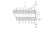
- FIG. 1 is a cross-sectional view showing a first embodiment of a laminate.
- FIG. 2 is a cross-sectional view showing a second embodiment of the laminate.
- FIG. 3 is a cross-sectional view showing a third embodiment of the laminate.
- FIG. 4 is a cross-sectional view showing a fourth embodiment of the laminate.
- FIG. 5 is a cross-sectional view showing a fifth embodiment of the laminate.
- FIG. 6 is a cross-sectional view showing a sixth embodiment of the laminate.
- FIG. 7 is a cross-sectional view showing a seventh embodiment of the laminate.
- FIG. 1 shows a first embodiment of a laminate according to the present invention.
- the laminated body 1 used for the protective cover of the touch panel is illustrated, but the laminated body 1 is not limited to this, and the laminated body 1 is used for panels for various electric / electronic devices such as a flat panel display (FPD) and a solar cell.
- the present invention can be used for building structures, panels for windows of various vehicles, protective covers for exhibits, and the like (the same applies to other embodiments).
- the laminate 1 includes a resin plate 2, a first glass sheet 3 bonded to one surface (hereinafter referred to as “first surface”) 2 a of the resin plate 2, and a resin plate 2.
- a second adhesive layer 6 for adhering the second glass sheet 4 to the second surface 2b of the resin plate 2 is provided and has a five-layer structure.
- a transparent material is used for the resin plate 2, the glass sheets 3 and 4, and the adhesive layers 5 and 6 constituting the laminate 1.
- the total thickness of the laminate 1 is preferably at least 3 times the sum of the thicknesses of the glass sheets 3 and 4 (the sum of the thicknesses of the first glass sheet 3 and the second glass sheet 4). More preferably, it is more preferably 10 times or more. Thereby, the weight reduction of the laminated body 1 can be achieved by increasing the ratio of the resin plate 2 to the laminated body 1.
- the thickness of the resin plate 2 is 0.01 mm or more and 20 mm or less, but when used for a protective cover of a touch panel mounted on a portable electronic device, it is 0.1 mm or more and 3 mm or less, particularly 0.1 mm or more and 2 mm or less. It is preferred that The material of the resin plate 2 is preferably polycarbonate or polymethacrylic acid methyl resin (PMMA). In addition, polyethylene terephthalate, polyetheretherketone (PEEK), polyamide, polyvinyl chloride, polyethylene, polypropylene, polyethylene naphthalate, etc. Various resin materials can be used.
- the resin plate 2 includes a resin film.
- the glass sheets 3 and 4 are preferably thinner than the resin plate 2 and have a thickness of 500 ⁇ m or less, preferably 10 ⁇ m or more and 300 ⁇ m or less, and more preferably 50 ⁇ m or more and 200 ⁇ m or less. Although it is preferable that the thickness of the 1st glass sheet 3 and the thickness of the 2nd glass sheet 4 are made the same, you may comprise the laminated body 1 by varying these thicknesses.
- the material of the glass sheets 3 and 4 silicate glass and silica glass are used, preferably borosilicate glass, soda lime glass, aluminosilicate glass, and chemically strengthened glass, and most preferably non-alkali glass. Used.
- the alkali-free glass is a glass that does not substantially contain an alkali component (alkali metal oxide), and specifically, a glass having a weight ratio of the alkali component of 3000 ppm or less. is there.
- the weight ratio of the alkali component in the present invention is preferably 1000 ppm or less, more preferably 500 ppm or less, and most preferably 300 ppm or less.
- the first glass sheet 3 and the second glass sheet 4 may be made of the same type of glass material, or may be made of different types of glass material.
- a glass sheet for example, the first glass sheet 3 on the side on which the user performs a touch operation is made of non-alkali glass that is superior in weather resistance and chemical resistance. It is also possible to use soda lime glass or the like for the opposite glass sheet (for example, the second glass sheet 4).
- the Young's modulus of the glass sheets 3 and 4 is 50 GPa or more, preferably 60 GPa or more, and most preferably 70 GPa or more.
- the glass sheets 3 and 4 can use a known float method, roll-out method, slot down draw method, redraw method, etc., but are preferably formed by the overflow down draw method.
- the overflow down draw method molten glass is poured into an overflow groove provided on the upper part of a substantially wedge-shaped cross section, and the molten glass overflowing on both sides from the overflow groove is formed along the side wall portions on both sides of the molded body. While flowing down, it is united and integrated at the lower end of the molded body, and one sheet glass is continuously formed.
- the glass sheets 3 and 4 having a thickness of 300 ⁇ m or less can be produced in large quantities and at low cost by the overflow downdraw method.
- the glass sheets 3 and 4 thus produced do not need to adjust the thickness of the glass sheets 3 and 4 by polishing, grinding, chemical etching, or the like.
- the overflow down draw method is a molding method in which both sides of the glass plate do not come into contact with the molded member at the time of molding, and both sides (translucent surface) of the obtained glass plate are fired surfaces and are high without polishing. Surface quality can be obtained. Thereby, the contact
- Each glass sheet 3, 4 has a surface (hereinafter referred to as “first surface”) 3 a, 4 a bonded to the resin plate 2 and a surface (hereinafter referred to as “first surface 3 a, 4 a) opposite to the first surface 3 a, 4 a. 3b, 4b) and end faces 3c, 4c formed between the first surfaces 3a, 4a and the second surfaces 3b, 4b.
- the first surface 3 a of the first glass sheet 3 is bonded to the first surface 2 a of the resin plate 2 by the first adhesive layer 5.
- the first surface 4 a of the second glass sheet 4 is bonded to the second surface 2 b of the resin plate 2 by the second adhesive layer 6.
- the second surfaces 3 b and 4 b of the glass sheets 3 and 4 constitute the outer surface of the laminate 1.
- the end surfaces 3 c and 4 c of the glass sheets 3 and 4 are arranged so as to be flush with the end surface 2 c of the resin plate 2.
- each adhesive layer 5 and 6 is 1 ⁇ m or more and 500 ⁇ m or less.
- materials for the adhesive layers 5 and 6 for example, ethylene vinyl acetate copolymer resin (EVA), polyvinyl butyral resin (PVB), and UV curable resin can be suitably used.
- EVA ethylene vinyl acetate copolymer resin
- PVB polyvinyl butyral resin
- UV curable resin can be suitably used.
- Silicone adhesive, rubber adhesive, UV curable acrylic adhesive, UV curable epoxy adhesive, thermosetting epoxy adhesive, thermosetting melamine adhesive, thermosetting phenol adhesive, etc. Can be used.
- the laminated body 1 is formed by protruding the first adhesive layer 5 and the second adhesive layer 6 from the end surface 2c of the resin plate 2 and the end surfaces 3c and 4c of the glass sheets 3 and 4, respectively.
- the protruding dimension (projecting dimension) D of the protruding portion 7 from the end faces 3c, 4c of the glass sheets 3, 4 is 0.01 mm or more and 5 mm or less, preferably 0.1 mm or more and 3 mm or less (other The same in the embodiment).
- the protruding portion 7 is configured integrally with the first adhesive layer 5 and the second adhesive layer 6, and is formed on the entire end surfaces 3 c and 4 c of the glass sheets 3 and 4 and on the entire end surface 2 c of the resin plate 2. In contact.
- the protrusion part 7 is in the state which contacted a part of 2nd surface 3b, 4b of each glass sheet 3,4.
- the range L in which the protruding portion 7 contacts the second surfaces 3b and 4b of the glass sheets 3 and 4 is preferably 1 mm or more and 3 mm or less (same in other embodiments).
- a method for producing the laminate 1 having the above configuration will be described.
- a resin plate 2 and glass sheets 3 and 4 having the same size (area) as the resin plate 2 are prepared.
- an adhesive layer for example, the first adhesive layer 5
- the resin plate 2 is laminated thereon, and the resin plate 2 is bonded to the resin plate 2.
- a layer for example, the second adhesive layer 6) is laminated, and the other glass sheet (for example, the second glass sheet 4) is laminated thereon.
- the adhesive layers 5 and 6 having a predetermined size are laminated so that the adhesive layers 5 and 6 protrude from the end surface 2c of the resin plate 2 and the end surfaces 3c and 4c of the glass sheets 3 and 4 in a later step. It is necessary to.
- the first adhesive layer 5 and the second adhesive layer 6 protrude from the end surface 2c of the resin plate 2 and the end surfaces 3c and 4c of the glass sheets 3 and 4, and the end surface 2c of the resin plate 2 and each glass It contacts the end surfaces 3c and 4c of the sheets 3 and 4, and further reaches the second surfaces 3b and 4b of the glass sheets 3 and 4, respectively.
- the protruding portion 7 formed in this way is cured while being integrated with the adhesive layers 5 and 6, and is firmly attached to the end surface 2c of the resin plate 2 and the end surfaces 3c and 4c of the glass sheets 3 and 4. It sticks to.
- the laminate 1 whose end is covered with the protruding portion 7 is completed.
- this adhesive is not used between the resin plate 2 and the glass sheets 3 and 4 without using an autoclave apparatus. Irradiate ultraviolet rays in the intervening state.
- the laminate 1 basically has a five-layer structure including the resin plate 2, the glass sheets 3 and 4, and the adhesive layers 5 and 6, but is not limited thereto, and is added to the first glass sheet 3, for example.
- a multilayer structure of 7 or more layers may be provided.
- an antireflection film layer or a contamination prevention film layer may be formed on the outer surface of the laminate 1, that is, on the second surfaces 3 b and 4 b of the glass sheets 3 and 4. These layers can be formed before the glass sheets 3 and 4 are bonded to the resin plate 2.
- the antireflection film layer is preferably made of an inorganic material, and more preferably an alternating film of a low refractive index layer and a high refractive index layer.
- the low refractive index layer is preferably one kind selected from the group consisting of silicon oxide, aluminum oxide and magnesium fluoride, and the total physical film thickness of the low refractive film on one side is preferably 100 nm to 700 nm.
- the high refractive index film is preferably one kind selected from the group consisting of silicon nitride, aluminum nitride, zirconium oxide, niobium oxide, tantalum oxide, hafnium oxide, titanium oxide, tin oxide and zinc oxide.
- the total physical film thickness of the high refractive index film is preferably 50 nm to 250 nm.
- sputtering As a method for forming the antireflection film layer on the glass sheets 3 and 4, sputtering, vacuum deposition, dipping, spin coating, ion plating, CVD, and the like can be used.
- the sputtering method is particularly advantageous in that the film becomes uniform, the adhesion to the glass sheets 3 and 4 becomes strong, and the film hardness increases.
- the protruding portion 7 caused by the adhesive layers 5 and 6 is in contact with the end faces 3c and 4c of the glass sheets 3 and 4. Therefore, even if other members contact from the side of the laminated body 1, these other members do not contact the end surfaces 3 c and 4 c of the glass sheets 3 and 4, but contact the protruding portion 7 that covers them. become.
- the protruding portion 7 is configured integrally with the adhesive layers 5 and 6 and is fixed to the end surfaces 3c and 4c of the glass sheets 3 and 4, so that even if other members come into contact with each other, the protruding portion 7 is difficult to drop off.
- the end faces 3c and 4c are firmly protected over a long period of time. Thereby, breakage of the end surfaces 3c and 4c of each glass sheet 3 and 4 and generation
- the adhesive layers 5 and 6 extend from the end surface 2 c of the resin plate 2 and the end surfaces 3 c and 4 c of the glass sheets 3 and 4. Since it is formed by protruding, it is formed at the same time in the step of bonding the glass sheets 3 and 4 to the resin plate 2. Therefore, it is not necessary to go through a process of pasting the resin on the end face of the laminate 1 after the fact as in the prior art. Therefore, in this invention, it is possible to manufacture a laminated body, without increasing a manufacturing man-hour.
- FIG. 2 shows a second embodiment of the laminate according to the present invention.
- the protrusion part 7 was comprised so that it might contact even a part of 2nd surface 3b, 4b of each glass sheet 3, 4, it eats in this embodiment.
- the lead-out portion 7 is not in contact with the second surfaces 3b and 4b, but is in contact with the entire end surfaces 3c and 4c of the glass sheets 3 and 4 and the entire end surface 2c of the resin plate 2, Cover and protect.
- FIG. 3 shows a third embodiment of the laminate according to the present invention.
- the protruding portion 7 is in contact with the entire end surface 2c of the resin plate 2, but the glass sheets 3 and 4 are not in contact with the entire end surfaces 3c and 4c but in contact with a part thereof. is doing.
- the range W where the protruding portion 7 contacts the end faces 3c and 4c of the glass sheets 3 and 4 is desirably half (1/2) or more of the thickness of the glass sheets 3 and 4 (the same in other embodiments). ).
- the protruding portion 7 is in contact with the end faces 3c and 4c over a range of about half the thickness of the glass sheets 3 and 4.
- the protruding portion 7 not only contacts the entire surface of the end faces 3c, 4c of the glass sheets 3, 4 as in the first and second embodiments, but also the glass sheets 3, 4
- the edge part of the laminated body 1 can be protected also by contacting a part of end surface 3c, 4c. That is, the protruding portion 7 can prevent damage or peeling of the glass sheets 3 and 4 by contacting at least part of the end surfaces 3c and 4c of the glass sheets 3 and 4.
- FIG. 4 shows a fourth embodiment of the laminate according to the present invention.
- the laminate 1 according to the present embodiment includes a first protruding portion 8 formed by the first adhesive layer 5 protruding from the end surface 2c of the resin plate 2 and the end surface 3c of the first glass sheet 3, and a resin.
- the first protruding portion 8 is in contact with a part of the end surface 3c of the first glass sheet 3. More specifically, the 1st protrusion part 8 is contacting the end surface 3c over the range to about half of the thickness of the 1st glass sheet 3. FIG. Further, the first protruding portion 8 is also in contact with a part of the end surface 2 c of the resin plate 2.
- the second protruding portion 9 is in contact with a part of the end surface 4c of the second glass sheet 4. More specifically, the 2nd protrusion part 9 is contacting the end surface 4c over the range to about half of the thickness of the 2nd glass sheet 4. FIG. Further, the second protruding portion 9 is also in contact with a part of the end surface 2 c of the resin plate 2.
- the first protruding portion 8 and the second protruding portion 9 in this embodiment are different from the first embodiment in the amount of each adhesive layer 5, 6.
- the protrusions are formed in two locations: a position corresponding to the first adhesive layer 5 and a position corresponding to the second adhesive layer 6.
- the first protruding portion 8 and the second protruding portion 8 and the second protruding portion are increased by increasing the protruding amount (volume) of each of the adhesive layers 5 and 6 as compared with the case of the present embodiment. It can be said that the protruding portion 9 is connected and integrated to form one protruding portion 7.
- FIG. 5 shows a fifth embodiment of the laminate according to the present invention.
- the structure of the 1st protrusion part 8 and the 2nd protrusion part 9 differs from 4th Embodiment.
- 4th Embodiment although the 1st protrusion part 8 was contacting a part of end surface 3c of the 1st glass sheet 3, it contacts the whole surface of the end surface 3c of the 1st glass sheet 3 in this embodiment.
- the first glass sheet 3 is also in contact with a part of the second surface 3b.
- the second protruding portion 9 is in contact with the entire end surface 4 c of the second glass sheet 4 and is also in contact with a part of the second surface 4 b of the second glass sheet 4.
- FIG. 6 shows a sixth embodiment of the laminate according to the present invention.
- the size (area) of the resin plate 2 is larger than the glass sheets 3 and 4, and the end surface 2 c of the resin plate 2 protrudes beyond the end surfaces 3 c and 4 c of the glass sheets 3 and 4. ing.
- the protruding dimension (hereinafter referred to as “first protruding dimension”) D1 of the protruding portions 8 and 9 from the end surfaces 3c and 4c of the glass sheets 3 and 4 and the end surface 2c of the resin plate 2 are shown.
- the protruding dimension (hereinafter referred to as “second protruding dimension”) D ⁇ b> 2 of each protruding portion 8, 9 is different.
- the second protrusion dimension D2 is smaller than the first protrusion dimension D1 (D2 ⁇ D1).
- the protruding portions 8 and 9 are in contact with part of the end surfaces 3 c and 4 c of the glass sheets 3 and 4, but are not in contact with the end surface 2 c of the resin plate 2.
- FIG. 7 shows a seventh embodiment of the laminate according to the present invention.
- the laminated body 1 which concerns on this embodiment differs in the structure of the 1st protrusion part 8 and the 2nd protrusion part 9 from 6th Embodiment.
- the protruding portions 8 and 9 are in contact with part of the end surfaces 3c and 4c of the glass sheets 3 and 4, but in the present embodiment, the protruding portions 8 and 9 are in contact. Is in contact with the entire end surfaces 3c and 4c of the glass sheets 3 and 4, and is also in contact with part of the second surfaces 3b and 4b of the glass sheets 3 and 4.
- the second protrusion dimension D2 is smaller than the first protrusion dimension D1 (D2 ⁇ D1).
- the laminated body which concerns on this invention is not limited to the structure of the said embodiment. Moreover, the laminated body which concerns on this invention is not limited to an above-described effect.
- the laminate according to the present invention can be variously modified without departing from the gist of the present invention.
- the protrusion part 7,8,9 showed the example which protrudes over the perimeter of the end surface 2c of the resin board 2, it is limited to this. Instead, the protruding portions 7, 8, and 9 only have to protrude from at least a part of the end surface 2 c of the resin plate 2.
- a test body (Example) of a laminate according to the second embodiment (see FIG. 2) was manufactured, and the effect was confirmed.
- a polycarbonate plate having a thickness of 151 mm ⁇ 201 mm and a thickness of 3.0 mm was used as the resin plate, and a glass plate having a thickness of 148 mm ⁇ 198 mm and a thickness of 200 ⁇ m was used.
- non-alkali glass product name: OA-10G
- Each adhesive layer was made of ethylene vinyl acetate copolymer resin (EVA) having a size of 150 mm ⁇ 200 mm and a thickness of 400 ⁇ m.
- EVA ethylene vinyl acetate copolymer resin
- thermocompression bonding was performed on the glass sheet using an autoclave device.
- thermocompression bonding was performed under the conditions of a heating temperature of 120 ° C., a pressure of 1 MPa, and a thermocompression bonding time of 1 hour.
- Twenty specimens were prepared by such a method, and a test on the presence or absence of peeling / damage was performed on each specimen. As a result, it was possible to confirm a sufficient prevention effect against peeling / damage for all the specimens.
Landscapes
- Laminated Bodies (AREA)
- Joining Of Glass To Other Materials (AREA)
Abstract
Description
2 樹脂板
2a 樹脂板の一方の面
2b 樹脂板の他方の面
2c 樹脂板の端面
3 第1ガラスシート
3a 第1ガラスシートの第1の面
3b 第1ガラスシートの第2の面
3c 第1ガラスシートの端面
4 第2ガラスシート
4a 第2ガラスシートの第1の面
4b 第2ガラスシートの第2の面
4c 第2ガラスシートの端面
5 第1接着層
6 第2接着層
7 食み出し部
8 第1食み出し部
9 第2食み出し部 DESCRIPTION OF
Claims (6)
- 接着層を介して樹脂板の両面にガラスシートを積層して一体化した積層体において、
前記ガラスシートは、前記樹脂板の一方の面に接着される第1ガラスシートと、前記樹脂板の他方の面に接着される第2ガラスシートとを含み、
前記接着層は、前記樹脂板の前記一方の面に前記第1ガラスシートを接着する第1接着層と、前記樹脂板の前記他方の面に前記第2ガラスシートを接着する第2接着層とを含み、
前記樹脂板の端面及び前記第1ガラスシートの端面から前記第1接着層が食み出ることにより形成される第1食み出し部と、前記樹脂板の端面及び前記第2ガラスシートの端面から前記第2接着層が食み出ることにより形成される第2食み出し部とを備え、
前記第1食み出し部は、前記第1ガラスシートの前記端面の少なくとも一部に接触し、前記第2食み出し部は、前記第2ガラスシートの前記端面の少なくとも一部に接触することを特徴とする積層体。 In a laminate in which glass sheets are laminated and integrated on both sides of a resin plate via an adhesive layer,
The glass sheet includes a first glass sheet bonded to one surface of the resin plate, and a second glass sheet bonded to the other surface of the resin plate,
The adhesive layer includes a first adhesive layer that adheres the first glass sheet to the one surface of the resin plate, and a second adhesive layer that adheres the second glass sheet to the other surface of the resin plate. Including
From the end surface of the resin plate and the end surface of the first glass sheet, the first protruding portion formed by the first adhesive layer protruding, and from the end surface of the resin plate and the end surface of the second glass sheet A second protruding portion formed by protruding the second adhesive layer,
The first protruding portion is in contact with at least part of the end surface of the first glass sheet, and the second protruding portion is in contact with at least part of the end surface of the second glass sheet. A laminate characterized by the following. - 前記第1食み出し部は、前記第1ガラスシートの厚みの半分以上の範囲にわたって前記第1ガラスシートの前記端面に接触し、前記第2食み出し部は、前記第2ガラスシートの厚みの半分以上の範囲にわたって前記第2ガラスシートの前記端面に接触することを特徴とする請求項1に記載の積層体。 The first protruding portion is in contact with the end surface of the first glass sheet over a range of half or more of the thickness of the first glass sheet, and the second protruding portion is a thickness of the second glass sheet. The laminate according to claim 1, wherein the laminate contacts with the end face of the second glass sheet over a range of more than half of the above.
- 前記第1ガラスシートは、前記第1接着層を介して前記樹脂板の前記一方の面に接着される第1の面と、前記第1の面とは反対側に位置する第2の面とを有し、
前記第2ガラスシートは、前記第2接着層を介して前記樹脂板の前記他方の面に接着される第1の面と、前記第1の面とは反対側に位置する第2の面とを有し、
前記第1食み出し部は、前記第1ガラスシートの前記端面の全面と前記第1ガラスシートの前記第2の面の少なくとも一部とに接触し、
前記第2食み出し部は、前記第2ガラスシートの前記端面の全面と前記第2ガラスシートの前記第2の面の少なくとも一部とに接触することを特徴とする請求項1又は2に記載の積層体。 The first glass sheet includes a first surface that is bonded to the one surface of the resin plate through the first adhesive layer, and a second surface that is located on the opposite side of the first surface. Have
The second glass sheet includes a first surface bonded to the other surface of the resin plate via the second adhesive layer, and a second surface located on the opposite side of the first surface. Have
The first protruding portion is in contact with the entire surface of the end surface of the first glass sheet and at least a part of the second surface of the first glass sheet;
The said 2nd protrusion part contacts the whole surface of the said end surface of the said 2nd glass sheet, and at least one part of the said 2nd surface of the said 2nd glass sheet, The said 1 or 2 The laminated body of description. - 前記第1食み出し部及び前記第2食み出し部は、前記樹脂板の前記端面の少なくとも一部に接触することを特徴とする請求項1から3のいずれか1項に記載の積層体。 4. The laminate according to claim 1, wherein the first protruding portion and the second protruding portion are in contact with at least a part of the end surface of the resin plate. .
- 前記第1食み出し部と前記第2食み出し部とが繋がって一体に構成されることを特徴とする請求項1から4のいずれか1項に記載の積層体。 The laminate according to any one of claims 1 to 4, wherein the first projecting portion and the second projecting portion are connected to each other and are integrally formed.
- 接着層を介して樹脂板の両面にガラスシートを積層一体化してなる積層体を製造する方法において、
前記樹脂板の端面及び前記ガラスシートの端面から前記接着層を食み出させることによって、前記接着層による食み出し部を形成するとともに、前記食み出し部を前記ガラスシートの前記端面の少なくとも一部に接触させることを特徴とする積層体の製造方法。 In the method for producing a laminate in which glass sheets are laminated and integrated on both surfaces of a resin plate via an adhesive layer,
By projecting the adhesive layer from the end surface of the resin plate and the end surface of the glass sheet, a protruding portion by the adhesive layer is formed, and the protruding portion is at least the end surface of the glass sheet. A method for producing a laminate, wherein the laminate is brought into contact with a part.
Priority Applications (4)
| Application Number | Priority Date | Filing Date | Title |
|---|---|---|---|
| CN201680004214.3A CN107001136B (en) | 2015-03-09 | 2016-03-02 | Laminate and method for producing same |
| KR1020177012583A KR102483097B1 (en) | 2015-03-09 | 2016-03-02 | Laminate body and manufacturing method thereof |
| JP2017505010A JP6700618B2 (en) | 2015-03-09 | 2016-03-02 | Laminated body and manufacturing method thereof |
| EP16761606.9A EP3269691B1 (en) | 2015-03-09 | 2016-03-02 | Method of manufacturing a laminate |
Applications Claiming Priority (2)
| Application Number | Priority Date | Filing Date | Title |
|---|---|---|---|
| JP2015-046113 | 2015-03-09 | ||
| JP2015046113 | 2015-03-09 |
Publications (1)
| Publication Number | Publication Date |
|---|---|
| WO2016143636A1 true WO2016143636A1 (en) | 2016-09-15 |
Family
ID=56879505
Family Applications (1)
| Application Number | Title | Priority Date | Filing Date |
|---|---|---|---|
| PCT/JP2016/056451 WO2016143636A1 (en) | 2015-03-09 | 2016-03-02 | Laminate body and manufacturing method thereof |
Country Status (6)
| Country | Link |
|---|---|
| EP (1) | EP3269691B1 (en) |
| JP (1) | JP6700618B2 (en) |
| KR (1) | KR102483097B1 (en) |
| CN (1) | CN107001136B (en) |
| TW (1) | TWI678281B (en) |
| WO (1) | WO2016143636A1 (en) |
Cited By (3)
| Publication number | Priority date | Publication date | Assignee | Title |
|---|---|---|---|---|
| JP2018176551A (en) * | 2017-04-13 | 2018-11-15 | 日本電気硝子株式会社 | Glass resin laminate |
| WO2021065805A1 (en) * | 2019-10-03 | 2021-04-08 | 日本電気硝子株式会社 | Multilayer body and method for producing multilayer body |
| WO2023074250A1 (en) * | 2021-10-28 | 2023-05-04 | 日本電気硝子株式会社 | Method for production of glass-resin laminate, and glass-resin laminate |
Families Citing this family (3)
| Publication number | Priority date | Publication date | Assignee | Title |
|---|---|---|---|---|
| DE202018107197U1 (en) * | 2018-12-17 | 2019-03-07 | Ferdi Inci | Bulletproof glass for automatic displays |
| JP2021018524A (en) * | 2019-07-18 | 2021-02-15 | 住友化学株式会社 | Optical laminate and manufacturing method |
| KR20230164812A (en) | 2022-05-26 | 2023-12-05 | 오상민 | LED Night Lighting System Using Fine Light Energy Charging Method of Sunlight |
Citations (4)
| Publication number | Priority date | Publication date | Assignee | Title |
|---|---|---|---|---|
| JPS5617953A (en) * | 1979-07-19 | 1981-02-20 | Tamotsu Nishi | Manufacture of laminated glass |
| JPH08281873A (en) * | 1995-04-12 | 1996-10-29 | Nitto Denzai Kk | Plate-shaped composite material |
| WO2012157610A1 (en) * | 2011-05-13 | 2012-11-22 | 日本電気硝子株式会社 | Laminate, method for cutting laminate, method for processing laminate, and device and method for cutting brittle plate-like object |
| JP2012254626A (en) * | 2011-05-13 | 2012-12-27 | Nippon Electric Glass Co Ltd | Laminate |
Family Cites Families (9)
| Publication number | Priority date | Publication date | Assignee | Title |
|---|---|---|---|---|
| DE10001795A1 (en) * | 2000-01-18 | 2001-07-19 | Bayer Ag | Composite pane consists of an inner pane made of a thermoplastic and outer panes made of glass joined by a thermoplastic polyurethane film |
| JP2002201049A (en) * | 2000-12-27 | 2002-07-16 | Asahi Glass Co Ltd | Laminated glass |
| KR101060352B1 (en) * | 2004-05-29 | 2011-08-29 | 엘지디스플레이 주식회사 | Manufacturing method of flexible display |
| DE102008052066B4 (en) * | 2008-10-17 | 2012-08-30 | Saint-Gobain Sekurit Deutschland Gmbh & Co. Kg | A laminated composite with a translucent or opaque stone layer, process for its preparation and its use |
| JP5510880B2 (en) * | 2009-03-26 | 2014-06-04 | 日本電気硝子株式会社 | Glass film laminate, glass roll of the laminate, and method for producing glass roll |
| DE202010008362U1 (en) * | 2010-08-25 | 2010-12-16 | Schott Ag | Transparent composite material for safety glazing |
| DE102012009788A1 (en) * | 2012-05-18 | 2013-11-21 | Schott Ag | Composite material for motor vehicles and aircraft components, has non-inorganic glass as core material and layer (s) arranged on core material and containing inorganic glass |
| DE102012215742A1 (en) * | 2012-09-05 | 2014-03-06 | Bundesdruckerei Gmbh | Safety and / or value product |
| EP3154784A2 (en) * | 2014-06-12 | 2017-04-19 | Corning Incorporated | Laminating thin glass structures |
-
2016
- 2016-03-02 EP EP16761606.9A patent/EP3269691B1/en active Active
- 2016-03-02 WO PCT/JP2016/056451 patent/WO2016143636A1/en active Application Filing
- 2016-03-02 CN CN201680004214.3A patent/CN107001136B/en active Active
- 2016-03-02 KR KR1020177012583A patent/KR102483097B1/en active IP Right Grant
- 2016-03-02 JP JP2017505010A patent/JP6700618B2/en active Active
- 2016-03-08 TW TW105107042A patent/TWI678281B/en active
Patent Citations (4)
| Publication number | Priority date | Publication date | Assignee | Title |
|---|---|---|---|---|
| JPS5617953A (en) * | 1979-07-19 | 1981-02-20 | Tamotsu Nishi | Manufacture of laminated glass |
| JPH08281873A (en) * | 1995-04-12 | 1996-10-29 | Nitto Denzai Kk | Plate-shaped composite material |
| WO2012157610A1 (en) * | 2011-05-13 | 2012-11-22 | 日本電気硝子株式会社 | Laminate, method for cutting laminate, method for processing laminate, and device and method for cutting brittle plate-like object |
| JP2012254626A (en) * | 2011-05-13 | 2012-12-27 | Nippon Electric Glass Co Ltd | Laminate |
Non-Patent Citations (1)
| Title |
|---|
| See also references of EP3269691A4 * |
Cited By (4)
| Publication number | Priority date | Publication date | Assignee | Title |
|---|---|---|---|---|
| JP2018176551A (en) * | 2017-04-13 | 2018-11-15 | 日本電気硝子株式会社 | Glass resin laminate |
| US20220176680A1 (en) * | 2017-04-13 | 2022-06-09 | Nippon Electric Glass Co., Ltd. | Glass resin laminate |
| WO2021065805A1 (en) * | 2019-10-03 | 2021-04-08 | 日本電気硝子株式会社 | Multilayer body and method for producing multilayer body |
| WO2023074250A1 (en) * | 2021-10-28 | 2023-05-04 | 日本電気硝子株式会社 | Method for production of glass-resin laminate, and glass-resin laminate |
Also Published As
| Publication number | Publication date |
|---|---|
| CN107001136B (en) | 2020-12-01 |
| TW201704018A (en) | 2017-02-01 |
| EP3269691B1 (en) | 2021-06-09 |
| CN107001136A (en) | 2017-08-01 |
| TWI678281B (en) | 2019-12-01 |
| JP6700618B2 (en) | 2020-05-27 |
| JPWO2016143636A1 (en) | 2018-01-11 |
| EP3269691A4 (en) | 2018-10-17 |
| KR102483097B1 (en) | 2022-12-30 |
| KR20170128768A (en) | 2017-11-23 |
| EP3269691A1 (en) | 2018-01-17 |
Similar Documents
| Publication | Publication Date | Title |
|---|---|---|
| WO2016143636A1 (en) | Laminate body and manufacturing method thereof | |
| EP3560899B1 (en) | Method for manufacturing curved laminated glass and curved laminated glass | |
| JP5999340B2 (en) | Glass film laminate for touch panel, touch panel, and method for producing glass film laminate for touch panel | |
| JP6186675B2 (en) | Glass resin laminate | |
| US20130114219A1 (en) | Opto-electronic frontplane substrate | |
| CN111063258A (en) | Cover plate, preparation method of cover plate and display device | |
| TWI489339B (en) | Touch sensor with decoration, method for manufacturing the same and touch sensor used in the same | |
| TW200909216A (en) | Laminated display window and device incorporating same | |
| US11227514B2 (en) | Cover, manufacturing method of cover, and display device | |
| KR20210045313A (en) | Laminated substrate and separation method | |
| TW201702073A (en) | Method for producing flexible laminate | |
| CN107980155B (en) | Touch screen and flexible display | |
| JP6593116B2 (en) | Plate with printing layer and display device using the same | |
| TW201841753A (en) | Glass resin laminate | |
| US11024831B2 (en) | Display apparatus and method for manufacturing display apparatus | |
| KR101699305B1 (en) | Tempered Glass for Mobile Devices | |
| JP2003157149A (en) | Touch panel having high durability | |
| KR20090086380A (en) | Silicon pad for touch pannel | |
| JP5084765B2 (en) | Touch panel | |
| JP2022166863A (en) | Laminate and manufacturing method for laminate | |
| WO2023074250A1 (en) | Method for production of glass-resin laminate, and glass-resin laminate | |
| WO2022080203A1 (en) | Glass laminate and method for manufacturing same | |
| US11161772B2 (en) | Thin multilayer laminate | |
| KR20180040758A (en) | Method for manufacturing the film for multilayer device with display of multi-shape mobile |
Legal Events
| Date | Code | Title | Description |
|---|---|---|---|
| 121 | Ep: the epo has been informed by wipo that ep was designated in this application |
Ref document number: 16761606 Country of ref document: EP Kind code of ref document: A1 |
|
| ENP | Entry into the national phase |
Ref document number: 2017505010 Country of ref document: JP Kind code of ref document: A |
|
| ENP | Entry into the national phase |
Ref document number: 20177012583 Country of ref document: KR Kind code of ref document: A |
|
| REEP | Request for entry into the european phase |
Ref document number: 2016761606 Country of ref document: EP |
|
| NENP | Non-entry into the national phase |
Ref country code: DE |