WO2016140254A1 - Carbon isotope analysis device and carbon isotope analysis method - Google Patents
Carbon isotope analysis device and carbon isotope analysis method Download PDFInfo
- Publication number
- WO2016140254A1 WO2016140254A1 PCT/JP2016/056390 JP2016056390W WO2016140254A1 WO 2016140254 A1 WO2016140254 A1 WO 2016140254A1 JP 2016056390 W JP2016056390 W JP 2016056390W WO 2016140254 A1 WO2016140254 A1 WO 2016140254A1
- Authority
- WO
- WIPO (PCT)
- Prior art keywords
- isotope
- carbon
- light
- carbon dioxide
- optical
- Prior art date
Links
- OKTJSMMVPCPJKN-UHFFFAOYSA-N Carbon Chemical compound [C] OKTJSMMVPCPJKN-UHFFFAOYSA-N 0.000 title claims abstract description 194
- 229910052799 carbon Inorganic materials 0.000 title claims abstract description 189
- 238000004458 analytical method Methods 0.000 title claims abstract description 43
- CURLTUGMZLYLDI-UHFFFAOYSA-N Carbon dioxide Chemical compound O=C=O CURLTUGMZLYLDI-UHFFFAOYSA-N 0.000 claims abstract description 224
- 230000003287 optical effect Effects 0.000 claims abstract description 162
- 239000001569 carbon dioxide Substances 0.000 claims abstract description 111
- 229910002092 carbon dioxide Inorganic materials 0.000 claims abstract description 111
- 239000013307 optical fiber Substances 0.000 claims abstract description 91
- 239000013078 crystal Substances 0.000 claims abstract description 66
- 238000002485 combustion reaction Methods 0.000 claims abstract description 27
- 238000000746 purification Methods 0.000 claims abstract description 13
- 238000006243 chemical reaction Methods 0.000 claims abstract description 10
- 230000005540 biological transmission Effects 0.000 claims abstract description 5
- 239000000523 sample Substances 0.000 claims description 75
- 238000000034 method Methods 0.000 claims description 56
- 238000010521 absorption reaction Methods 0.000 claims description 49
- 239000012472 biological sample Substances 0.000 claims description 40
- 239000000835 fiber Substances 0.000 claims description 30
- 239000003960 organic solvent Substances 0.000 claims description 25
- 230000002285 radioactive effect Effects 0.000 claims description 22
- 230000003595 spectral effect Effects 0.000 claims description 21
- 238000001228 spectrum Methods 0.000 claims description 17
- 238000001816 cooling Methods 0.000 claims description 16
- 238000001514 detection method Methods 0.000 claims description 15
- 230000035945 sensitivity Effects 0.000 claims description 14
- 238000000926 separation method Methods 0.000 claims description 9
- ZZEMEJKDTZOXOI-UHFFFAOYSA-N digallium;selenium(2-) Chemical compound [Ga+3].[Ga+3].[Se-2].[Se-2].[Se-2] ZZEMEJKDTZOXOI-UHFFFAOYSA-N 0.000 claims description 4
- 238000011049 filling Methods 0.000 claims description 2
- OKTJSMMVPCPJKN-NJFSPNSNSA-N Carbon-14 Chemical compound [14C] OKTJSMMVPCPJKN-NJFSPNSNSA-N 0.000 abstract 1
- 238000005259 measurement Methods 0.000 description 62
- 239000007789 gas Substances 0.000 description 46
- 238000010586 diagram Methods 0.000 description 30
- 210000002381 plasma Anatomy 0.000 description 23
- 210000002700 urine Anatomy 0.000 description 21
- 238000000180 cavity ring-down spectroscopy Methods 0.000 description 20
- WEVYAHXRMPXWCK-UHFFFAOYSA-N Acetonitrile Chemical compound CC#N WEVYAHXRMPXWCK-UHFFFAOYSA-N 0.000 description 19
- 230000004048 modification Effects 0.000 description 17
- 108090000623 proteins and genes Proteins 0.000 description 17
- 102000004169 proteins and genes Human genes 0.000 description 17
- XLYOFNOQVPJJNP-UHFFFAOYSA-N water Chemical compound O XLYOFNOQVPJJNP-UHFFFAOYSA-N 0.000 description 17
- 238000012986 modification Methods 0.000 description 16
- 230000008569 process Effects 0.000 description 14
- 150000001875 compounds Chemical class 0.000 description 13
- 229910052757 nitrogen Inorganic materials 0.000 description 13
- OKKJLVBELUTLKV-UHFFFAOYSA-N Methanol Chemical compound OC OKKJLVBELUTLKV-UHFFFAOYSA-N 0.000 description 12
- 239000003054 catalyst Substances 0.000 description 12
- 238000002203 pretreatment Methods 0.000 description 12
- 101150039403 ams gene Proteins 0.000 description 11
- 210000004369 blood Anatomy 0.000 description 11
- 239000008280 blood Substances 0.000 description 11
- 229910002091 carbon monoxide Inorganic materials 0.000 description 11
- 238000002474 experimental method Methods 0.000 description 10
- 238000004519 manufacturing process Methods 0.000 description 10
- 238000006722 reduction reaction Methods 0.000 description 10
- 239000000243 solution Substances 0.000 description 10
- WQZGKKKJIJFFOK-GASJEMHNSA-N Glucose Natural products OC[C@H]1OC(O)[C@H](O)[C@@H](O)[C@@H]1O WQZGKKKJIJFFOK-GASJEMHNSA-N 0.000 description 9
- 210000003608 fece Anatomy 0.000 description 9
- 239000008103 glucose Substances 0.000 description 9
- 238000002414 normal-phase solid-phase extraction Methods 0.000 description 9
- IJGRMHOSHXDMSA-UHFFFAOYSA-N Atomic nitrogen Chemical compound N#N IJGRMHOSHXDMSA-UHFFFAOYSA-N 0.000 description 8
- 239000006185 dispersion Substances 0.000 description 8
- 230000009467 reduction Effects 0.000 description 8
- 238000000638 solvent extraction Methods 0.000 description 8
- 239000000126 substance Substances 0.000 description 8
- 239000003814 drug Substances 0.000 description 7
- 230000000694 effects Effects 0.000 description 7
- 238000011156 evaluation Methods 0.000 description 7
- 238000000622 liquid--liquid extraction Methods 0.000 description 7
- 230000003647 oxidation Effects 0.000 description 7
- 238000007254 oxidation reaction Methods 0.000 description 7
- 229910052760 oxygen Inorganic materials 0.000 description 7
- 238000011084 recovery Methods 0.000 description 7
- 239000007787 solid Substances 0.000 description 7
- RZVAJINKPMORJF-UHFFFAOYSA-N Acetaminophen Chemical compound CC(=O)NC1=CC=C(O)C=C1 RZVAJINKPMORJF-UHFFFAOYSA-N 0.000 description 6
- ATJFFYVFTNAWJD-UHFFFAOYSA-N Tin Chemical compound [Sn] ATJFFYVFTNAWJD-UHFFFAOYSA-N 0.000 description 6
- 229910002804 graphite Inorganic materials 0.000 description 6
- 239000010439 graphite Substances 0.000 description 6
- 238000002156 mixing Methods 0.000 description 6
- 230000002829 reductive effect Effects 0.000 description 6
- 238000000108 ultra-filtration Methods 0.000 description 6
- 241000700159 Rattus Species 0.000 description 5
- QVGXLLKOCUKJST-UHFFFAOYSA-N atomic oxygen Chemical compound [O] QVGXLLKOCUKJST-UHFFFAOYSA-N 0.000 description 5
- 238000004364 calculation method Methods 0.000 description 5
- 239000002775 capsule Substances 0.000 description 5
- 239000012159 carrier gas Substances 0.000 description 5
- 238000002309 gasification Methods 0.000 description 5
- 239000000463 material Substances 0.000 description 5
- 239000001301 oxygen Substances 0.000 description 5
- 229960005489 paracetamol Drugs 0.000 description 5
- 230000036961 partial effect Effects 0.000 description 5
- 239000004038 photonic crystal Substances 0.000 description 5
- 238000003672 processing method Methods 0.000 description 5
- LFQSCWFLJHTTHZ-UHFFFAOYSA-N Ethanol Chemical compound CCO LFQSCWFLJHTTHZ-UHFFFAOYSA-N 0.000 description 4
- 238000000862 absorption spectrum Methods 0.000 description 4
- 238000004760 accelerator mass spectrometry Methods 0.000 description 4
- 239000007864 aqueous solution Substances 0.000 description 4
- 210000000941 bile Anatomy 0.000 description 4
- 230000008859 change Effects 0.000 description 4
- 230000003544 deproteinization Effects 0.000 description 4
- 238000010790 dilution Methods 0.000 description 4
- 239000012895 dilution Substances 0.000 description 4
- 230000002550 fecal effect Effects 0.000 description 4
- 230000006870 function Effects 0.000 description 4
- 238000004817 gas chromatography Methods 0.000 description 4
- 239000000203 mixture Substances 0.000 description 4
- 239000012071 phase Substances 0.000 description 4
- BASFCYQUMIYNBI-UHFFFAOYSA-N platinum Chemical compound [Pt] BASFCYQUMIYNBI-UHFFFAOYSA-N 0.000 description 4
- 238000002310 reflectometry Methods 0.000 description 4
- 241000282412 Homo Species 0.000 description 3
- MWUXSHHQAYIFBG-UHFFFAOYSA-N Nitric oxide Chemical compound O=[N] MWUXSHHQAYIFBG-UHFFFAOYSA-N 0.000 description 3
- VYPSYNLAJGMNEJ-UHFFFAOYSA-N Silicium dioxide Chemical compound O=[Si]=O VYPSYNLAJGMNEJ-UHFFFAOYSA-N 0.000 description 3
- BQCADISMDOOEFD-UHFFFAOYSA-N Silver Chemical compound [Ag] BQCADISMDOOEFD-UHFFFAOYSA-N 0.000 description 3
- 239000011358 absorbing material Substances 0.000 description 3
- 238000011088 calibration curve Methods 0.000 description 3
- 229910052802 copper Inorganic materials 0.000 description 3
- 239000010949 copper Substances 0.000 description 3
- 238000003795 desorption Methods 0.000 description 3
- 229940079593 drug Drugs 0.000 description 3
- 238000001035 drying Methods 0.000 description 3
- 230000007613 environmental effect Effects 0.000 description 3
- 239000003230 hygroscopic agent Substances 0.000 description 3
- 230000031700 light absorption Effects 0.000 description 3
- 230000001590 oxidative effect Effects 0.000 description 3
- 239000004332 silver Substances 0.000 description 3
- 239000002904 solvent Substances 0.000 description 3
- RNFJDJUURJAICM-UHFFFAOYSA-N 2,2,4,4,6,6-hexaphenoxy-1,3,5-triaza-2$l^{5},4$l^{5},6$l^{5}-triphosphacyclohexa-1,3,5-triene Chemical compound N=1P(OC=2C=CC=CC=2)(OC=2C=CC=CC=2)=NP(OC=2C=CC=CC=2)(OC=2C=CC=CC=2)=NP=1(OC=1C=CC=CC=1)OC1=CC=CC=C1 RNFJDJUURJAICM-UHFFFAOYSA-N 0.000 description 2
- 101100068867 Caenorhabditis elegans glc-1 gene Proteins 0.000 description 2
- VTYYLEPIZMXCLO-UHFFFAOYSA-L Calcium carbonate Chemical compound [Ca+2].[O-]C([O-])=O VTYYLEPIZMXCLO-UHFFFAOYSA-L 0.000 description 2
- BVKZGUZCCUSVTD-UHFFFAOYSA-L Carbonate Chemical compound [O-]C([O-])=O BVKZGUZCCUSVTD-UHFFFAOYSA-L 0.000 description 2
- 229910020366 ClO 4 Inorganic materials 0.000 description 2
- QPLDLSVMHZLSFG-UHFFFAOYSA-N Copper oxide Chemical compound [Cu]=O QPLDLSVMHZLSFG-UHFFFAOYSA-N 0.000 description 2
- 239000005751 Copper oxide Substances 0.000 description 2
- KRHYYFGTRYWZRS-UHFFFAOYSA-M Fluoride anion Chemical group [F-] KRHYYFGTRYWZRS-UHFFFAOYSA-M 0.000 description 2
- MHAJPDPJQMAIIY-UHFFFAOYSA-N Hydrogen peroxide Chemical compound OO MHAJPDPJQMAIIY-UHFFFAOYSA-N 0.000 description 2
- FFEARJCKVFRZRR-BYPYZUCNSA-N L-methionine Chemical compound CSCC[C@H](N)C(O)=O FFEARJCKVFRZRR-BYPYZUCNSA-N 0.000 description 2
- 241000124008 Mammalia Species 0.000 description 2
- 229920000557 Nafion® Polymers 0.000 description 2
- NBIIXXVUZAFLBC-UHFFFAOYSA-N Phosphoric acid Chemical compound OP(O)(O)=O NBIIXXVUZAFLBC-UHFFFAOYSA-N 0.000 description 2
- 238000004847 absorption spectroscopy Methods 0.000 description 2
- 239000003463 adsorbent Substances 0.000 description 2
- 230000000903 blocking effect Effects 0.000 description 2
- 235000011089 carbon dioxide Nutrition 0.000 description 2
- 238000010000 carbonizing Methods 0.000 description 2
- 229910000428 cobalt oxide Inorganic materials 0.000 description 2
- IVMYJDGYRUAWML-UHFFFAOYSA-N cobalt(ii) oxide Chemical compound [Co]=O IVMYJDGYRUAWML-UHFFFAOYSA-N 0.000 description 2
- 238000009833 condensation Methods 0.000 description 2
- 230000005494 condensation Effects 0.000 description 2
- -1 copper Halogen Chemical class 0.000 description 2
- 229910000431 copper oxide Inorganic materials 0.000 description 2
- 230000007423 decrease Effects 0.000 description 2
- 238000011161 development Methods 0.000 description 2
- YWEUIGNSBFLMFL-UHFFFAOYSA-N diphosphonate Chemical compound O=P(=O)OP(=O)=O YWEUIGNSBFLMFL-UHFFFAOYSA-N 0.000 description 2
- 238000000605 extraction Methods 0.000 description 2
- 239000003063 flame retardant Substances 0.000 description 2
- 239000005350 fused silica glass Substances 0.000 description 2
- 229910052736 halogen Inorganic materials 0.000 description 2
- 230000006872 improvement Effects 0.000 description 2
- 239000012535 impurity Substances 0.000 description 2
- 238000009434 installation Methods 0.000 description 2
- 238000009413 insulation Methods 0.000 description 2
- 238000002955 isolation Methods 0.000 description 2
- 239000007788 liquid Substances 0.000 description 2
- 210000004072 lung Anatomy 0.000 description 2
- 239000011159 matrix material Substances 0.000 description 2
- 230000007246 mechanism Effects 0.000 description 2
- 239000012528 membrane Substances 0.000 description 2
- 239000002207 metabolite Substances 0.000 description 2
- 229930182817 methionine Natural products 0.000 description 2
- 239000002808 molecular sieve Substances 0.000 description 2
- 238000012544 monitoring process Methods 0.000 description 2
- 210000000056 organ Anatomy 0.000 description 2
- DLYUQMMRRRQYAE-UHFFFAOYSA-N phosphorus pentoxide Inorganic materials O1P(O2)(=O)OP3(=O)OP1(=O)OP2(=O)O3 DLYUQMMRRRQYAE-UHFFFAOYSA-N 0.000 description 2
- 229910052697 platinum Inorganic materials 0.000 description 2
- 230000010287 polarization Effects 0.000 description 2
- 238000002360 preparation method Methods 0.000 description 2
- 230000005855 radiation Effects 0.000 description 2
- 229910052709 silver Inorganic materials 0.000 description 2
- URGAHOPLAPQHLN-UHFFFAOYSA-N sodium aluminosilicate Chemical compound [Na+].[Al+3].[O-][Si]([O-])=O.[O-][Si]([O-])=O URGAHOPLAPQHLN-UHFFFAOYSA-N 0.000 description 2
- 239000007790 solid phase Substances 0.000 description 2
- 238000003860 storage Methods 0.000 description 2
- FDDDEECHVMSUSB-UHFFFAOYSA-N sulfanilamide Chemical compound NC1=CC=C(S(N)(=O)=O)C=C1 FDDDEECHVMSUSB-UHFFFAOYSA-N 0.000 description 2
- 229940124530 sulfonamide Drugs 0.000 description 2
- 229910052717 sulfur Inorganic materials 0.000 description 2
- 238000012360 testing method Methods 0.000 description 2
- 238000005303 weighing Methods 0.000 description 2
- WSMQKESQZFQMFW-UHFFFAOYSA-N 5-methyl-pyrazole-3-carboxylic acid Chemical compound CC1=CC(C(O)=O)=NN1 WSMQKESQZFQMFW-UHFFFAOYSA-N 0.000 description 1
- 241000283690 Bos taurus Species 0.000 description 1
- 241000282472 Canis lupus familiaris Species 0.000 description 1
- 241000283707 Capra Species 0.000 description 1
- 241000700198 Cavia Species 0.000 description 1
- 241000282693 Cercopithecidae Species 0.000 description 1
- RYGMFSIKBFXOCR-UHFFFAOYSA-N Copper Chemical compound [Cu] RYGMFSIKBFXOCR-UHFFFAOYSA-N 0.000 description 1
- 241000196324 Embryophyta Species 0.000 description 1
- 241000283086 Equidae Species 0.000 description 1
- 229910052691 Erbium Inorganic materials 0.000 description 1
- 241000282326 Felis catus Species 0.000 description 1
- 229910005543 GaSe Inorganic materials 0.000 description 1
- UFHFLCQGNIYNRP-UHFFFAOYSA-N Hydrogen Chemical compound [H][H] UFHFLCQGNIYNRP-UHFFFAOYSA-N 0.000 description 1
- XEEYBQQBJWHFJM-UHFFFAOYSA-N Iron Chemical compound [Fe] XEEYBQQBJWHFJM-UHFFFAOYSA-N 0.000 description 1
- 241001465754 Metazoa Species 0.000 description 1
- 241000699666 Mus <mouse, genus> Species 0.000 description 1
- 241000699670 Mus sp. Species 0.000 description 1
- 241000283973 Oryctolagus cuniculus Species 0.000 description 1
- 241001494479 Pecora Species 0.000 description 1
- 238000001069 Raman spectroscopy Methods 0.000 description 1
- 241000282887 Suidae Species 0.000 description 1
- NINIDFKCEFEMDL-UHFFFAOYSA-N Sulfur Chemical compound [S] NINIDFKCEFEMDL-UHFFFAOYSA-N 0.000 description 1
- 229910052769 Ytterbium Inorganic materials 0.000 description 1
- 239000006096 absorbing agent Substances 0.000 description 1
- 239000002253 acid Substances 0.000 description 1
- 230000009471 action Effects 0.000 description 1
- PNEYBMLMFCGWSK-UHFFFAOYSA-N aluminium oxide Inorganic materials [O-2].[O-2].[O-2].[Al+3].[Al+3] PNEYBMLMFCGWSK-UHFFFAOYSA-N 0.000 description 1
- 229910000147 aluminium phosphate Inorganic materials 0.000 description 1
- 150000001412 amines Chemical class 0.000 description 1
- 239000000538 analytical sample Substances 0.000 description 1
- 230000002547 anomalous effect Effects 0.000 description 1
- 230000008901 benefit Effects 0.000 description 1
- WQZGKKKJIJFFOK-VFUOTHLCSA-N beta-D-glucose Chemical compound OC[C@H]1O[C@@H](O)[C@H](O)[C@@H](O)[C@@H]1O WQZGKKKJIJFFOK-VFUOTHLCSA-N 0.000 description 1
- 239000012496 blank sample Substances 0.000 description 1
- 210000001124 body fluid Anatomy 0.000 description 1
- 239000010839 body fluid Substances 0.000 description 1
- 210000004556 brain Anatomy 0.000 description 1
- 229910000019 calcium carbonate Inorganic materials 0.000 description 1
- AXCZMVOFGPJBDE-UHFFFAOYSA-L calcium dihydroxide Chemical compound [OH-].[OH-].[Ca+2] AXCZMVOFGPJBDE-UHFFFAOYSA-L 0.000 description 1
- 239000000920 calcium hydroxide Substances 0.000 description 1
- 229910001861 calcium hydroxide Inorganic materials 0.000 description 1
- 238000004177 carbon cycle Methods 0.000 description 1
- 210000003169 central nervous system Anatomy 0.000 description 1
- 238000005119 centrifugation Methods 0.000 description 1
- 239000003153 chemical reaction reagent Substances 0.000 description 1
- 239000003638 chemical reducing agent Substances 0.000 description 1
- 239000003795 chemical substances by application Substances 0.000 description 1
- 238000004140 cleaning Methods 0.000 description 1
- 230000002860 competitive effect Effects 0.000 description 1
- 238000012790 confirmation Methods 0.000 description 1
- 239000000356 contaminant Substances 0.000 description 1
- 238000011109 contamination Methods 0.000 description 1
- 229910052593 corundum Inorganic materials 0.000 description 1
- 238000005520 cutting process Methods 0.000 description 1
- 230000009089 cytolysis Effects 0.000 description 1
- 238000004042 decolorization Methods 0.000 description 1
- 230000000593 degrading effect Effects 0.000 description 1
- 238000007791 dehumidification Methods 0.000 description 1
- 239000002274 desiccant Substances 0.000 description 1
- 238000013461 design Methods 0.000 description 1
- 238000000502 dialysis Methods 0.000 description 1
- 238000007865 diluting Methods 0.000 description 1
- 239000002612 dispersion medium Substances 0.000 description 1
- 239000012153 distilled water Substances 0.000 description 1
- 238000012912 drug discovery process Methods 0.000 description 1
- 230000000857 drug effect Effects 0.000 description 1
- 238000005538 encapsulation Methods 0.000 description 1
- UYAHIZSMUZPPFV-UHFFFAOYSA-N erbium Chemical compound [Er] UYAHIZSMUZPPFV-UHFFFAOYSA-N 0.000 description 1
- 238000001914 filtration Methods 0.000 description 1
- 238000001917 fluorescence detection Methods 0.000 description 1
- 238000007710 freezing Methods 0.000 description 1
- 230000008014 freezing Effects 0.000 description 1
- 239000000499 gel Substances 0.000 description 1
- 239000011521 glass Substances 0.000 description 1
- 210000002216 heart Anatomy 0.000 description 1
- 238000010438 heat treatment Methods 0.000 description 1
- 239000001307 helium Substances 0.000 description 1
- 229910052734 helium Inorganic materials 0.000 description 1
- SWQJXJOGLNCZEY-UHFFFAOYSA-N helium atom Chemical compound [He] SWQJXJOGLNCZEY-UHFFFAOYSA-N 0.000 description 1
- 238000004128 high performance liquid chromatography Methods 0.000 description 1
- 239000012510 hollow fiber Substances 0.000 description 1
- 230000008676 import Effects 0.000 description 1
- 238000002347 injection Methods 0.000 description 1
- 239000007924 injection Substances 0.000 description 1
- 238000004255 ion exchange chromatography Methods 0.000 description 1
- 239000003456 ion exchange resin Substances 0.000 description 1
- 229920003303 ion-exchange polymer Polymers 0.000 description 1
- 230000001678 irradiating effect Effects 0.000 description 1
- 210000003734 kidney Anatomy 0.000 description 1
- 239000004973 liquid crystal related substance Substances 0.000 description 1
- 238000005567 liquid scintillation counting Methods 0.000 description 1
- GQYHUHYESMUTHG-UHFFFAOYSA-N lithium niobate Chemical compound [Li+].[O-][Nb](=O)=O GQYHUHYESMUTHG-UHFFFAOYSA-N 0.000 description 1
- 210000004185 liver Anatomy 0.000 description 1
- 230000002934 lysing effect Effects 0.000 description 1
- 244000005700 microbiome Species 0.000 description 1
- 238000002715 modification method Methods 0.000 description 1
- 238000011017 operating method Methods 0.000 description 1
- 230000000144 pharmacologic effect Effects 0.000 description 1
- 239000000049 pigment Substances 0.000 description 1
- 229920000642 polymer Polymers 0.000 description 1
- 229920005597 polymer membrane Polymers 0.000 description 1
- 238000003825 pressing Methods 0.000 description 1
- 238000012545 processing Methods 0.000 description 1
- 238000011002 quantification Methods 0.000 description 1
- 238000007670 refining Methods 0.000 description 1
- 230000000717 retained effect Effects 0.000 description 1
- 210000003296 saliva Anatomy 0.000 description 1
- 229910052594 sapphire Inorganic materials 0.000 description 1
- 239000010980 sapphire Substances 0.000 description 1
- 230000028327 secretion Effects 0.000 description 1
- 239000004065 semiconductor Substances 0.000 description 1
- 210000002966 serum Anatomy 0.000 description 1
- 230000035939 shock Effects 0.000 description 1
- 239000000741 silica gel Substances 0.000 description 1
- 229910002027 silica gel Inorganic materials 0.000 description 1
- 229910001923 silver oxide Inorganic materials 0.000 description 1
- 210000003491 skin Anatomy 0.000 description 1
- HUAUNKAZQWMVFY-UHFFFAOYSA-M sodium;oxocalcium;hydroxide Chemical compound [OH-].[Na+].[Ca]=O HUAUNKAZQWMVFY-UHFFFAOYSA-M 0.000 description 1
- 239000002594 sorbent Substances 0.000 description 1
- 238000004611 spectroscopical analysis Methods 0.000 description 1
- 239000002915 spent fuel radioactive waste Substances 0.000 description 1
- 239000012086 standard solution Substances 0.000 description 1
- 239000011593 sulfur Substances 0.000 description 1
- 230000036962 time dependent Effects 0.000 description 1
- 230000001988 toxicity Effects 0.000 description 1
- 231100000419 toxicity Toxicity 0.000 description 1
- 229910021642 ultra pure water Inorganic materials 0.000 description 1
- 239000012498 ultrapure water Substances 0.000 description 1
- 238000011144 upstream manufacturing Methods 0.000 description 1
- 239000003643 water by type Substances 0.000 description 1
- 229910001845 yogo sapphire Inorganic materials 0.000 description 1
- NAWDYIZEMPQZHO-UHFFFAOYSA-N ytterbium Chemical compound [Yb] NAWDYIZEMPQZHO-UHFFFAOYSA-N 0.000 description 1
Images


Classifications
-
- G—PHYSICS
- G01—MEASURING; TESTING
- G01N—INVESTIGATING OR ANALYSING MATERIALS BY DETERMINING THEIR CHEMICAL OR PHYSICAL PROPERTIES
- G01N21/00—Investigating or analysing materials by the use of optical means, i.e. using sub-millimetre waves, infrared, visible or ultraviolet light
- G01N21/17—Systems in which incident light is modified in accordance with the properties of the material investigated
- G01N21/25—Colour; Spectral properties, i.e. comparison of effect of material on the light at two or more different wavelengths or wavelength bands
- G01N21/31—Investigating relative effect of material at wavelengths characteristic of specific elements or molecules, e.g. atomic absorption spectrometry
- G01N21/35—Investigating relative effect of material at wavelengths characteristic of specific elements or molecules, e.g. atomic absorption spectrometry using infrared light
- G01N21/3504—Investigating relative effect of material at wavelengths characteristic of specific elements or molecules, e.g. atomic absorption spectrometry using infrared light for analysing gases, e.g. multi-gas analysis
-
- G—PHYSICS
- G01—MEASURING; TESTING
- G01J—MEASUREMENT OF INTENSITY, VELOCITY, SPECTRAL CONTENT, POLARISATION, PHASE OR PULSE CHARACTERISTICS OF INFRARED, VISIBLE OR ULTRAVIOLET LIGHT; COLORIMETRY; RADIATION PYROMETRY
- G01J3/00—Spectrometry; Spectrophotometry; Monochromators; Measuring colours
- G01J3/02—Details
- G01J3/0205—Optical elements not provided otherwise, e.g. optical manifolds, diffusers, windows
- G01J3/0218—Optical elements not provided otherwise, e.g. optical manifolds, diffusers, windows using optical fibers
-
- G—PHYSICS
- G01—MEASURING; TESTING
- G01J—MEASUREMENT OF INTENSITY, VELOCITY, SPECTRAL CONTENT, POLARISATION, PHASE OR PULSE CHARACTERISTICS OF INFRARED, VISIBLE OR ULTRAVIOLET LIGHT; COLORIMETRY; RADIATION PYROMETRY
- G01J1/00—Photometry, e.g. photographic exposure meter
- G01J1/10—Photometry, e.g. photographic exposure meter by comparison with reference light or electric value provisionally void
- G01J1/12—Photometry, e.g. photographic exposure meter by comparison with reference light or electric value provisionally void using wholly visual means
- G01J1/122—Visual exposure meters for determining the exposure time in photographical recording or reproducing
- G01J1/124—Visual exposure meters for determining the exposure time in photographical recording or reproducing based on the comparison of the intensity of measured light with a comparison source or comparison illuminated surface
-
- G—PHYSICS
- G01—MEASURING; TESTING
- G01J—MEASUREMENT OF INTENSITY, VELOCITY, SPECTRAL CONTENT, POLARISATION, PHASE OR PULSE CHARACTERISTICS OF INFRARED, VISIBLE OR ULTRAVIOLET LIGHT; COLORIMETRY; RADIATION PYROMETRY
- G01J3/00—Spectrometry; Spectrophotometry; Monochromators; Measuring colours
- G01J3/02—Details
- G01J3/0205—Optical elements not provided otherwise, e.g. optical manifolds, diffusers, windows
- G01J3/0208—Optical elements not provided otherwise, e.g. optical manifolds, diffusers, windows using focussing or collimating elements, e.g. lenses or mirrors; performing aberration correction
-
- G—PHYSICS
- G01—MEASURING; TESTING
- G01J—MEASUREMENT OF INTENSITY, VELOCITY, SPECTRAL CONTENT, POLARISATION, PHASE OR PULSE CHARACTERISTICS OF INFRARED, VISIBLE OR ULTRAVIOLET LIGHT; COLORIMETRY; RADIATION PYROMETRY
- G01J3/00—Spectrometry; Spectrophotometry; Monochromators; Measuring colours
- G01J3/28—Investigating the spectrum
- G01J3/42—Absorption spectrometry; Double beam spectrometry; Flicker spectrometry; Reflection spectrometry
-
- G—PHYSICS
- G01—MEASURING; TESTING
- G01N—INVESTIGATING OR ANALYSING MATERIALS BY DETERMINING THEIR CHEMICAL OR PHYSICAL PROPERTIES
- G01N21/00—Investigating or analysing materials by the use of optical means, i.e. using sub-millimetre waves, infrared, visible or ultraviolet light
- G01N21/01—Arrangements or apparatus for facilitating the optical investigation
-
- G—PHYSICS
- G01—MEASURING; TESTING
- G01N—INVESTIGATING OR ANALYSING MATERIALS BY DETERMINING THEIR CHEMICAL OR PHYSICAL PROPERTIES
- G01N30/00—Investigating or analysing materials by separation into components using adsorption, absorption or similar phenomena or using ion-exchange, e.g. chromatography or field flow fractionation
- G01N30/02—Column chromatography
- G01N30/88—Integrated analysis systems specially adapted therefor, not covered by a single one of the groups G01N30/04 - G01N30/86
-
- G—PHYSICS
- G02—OPTICS
- G02B—OPTICAL ELEMENTS, SYSTEMS OR APPARATUS
- G02B27/00—Optical systems or apparatus not provided for by any of the groups G02B1/00 - G02B26/00, G02B30/00
- G02B27/10—Beam splitting or combining systems
- G02B27/1006—Beam splitting or combining systems for splitting or combining different wavelengths
-
- G—PHYSICS
- G02—OPTICS
- G02B—OPTICAL ELEMENTS, SYSTEMS OR APPARATUS
- G02B5/00—Optical elements other than lenses
- G02B5/08—Mirrors
-
- G—PHYSICS
- G02—OPTICS
- G02F—OPTICAL DEVICES OR ARRANGEMENTS FOR THE CONTROL OF LIGHT BY MODIFICATION OF THE OPTICAL PROPERTIES OF THE MEDIA OF THE ELEMENTS INVOLVED THEREIN; NON-LINEAR OPTICS; FREQUENCY-CHANGING OF LIGHT; OPTICAL LOGIC ELEMENTS; OPTICAL ANALOGUE/DIGITAL CONVERTERS
- G02F1/00—Devices or arrangements for the control of the intensity, colour, phase, polarisation or direction of light arriving from an independent light source, e.g. switching, gating or modulating; Non-linear optics
- G02F1/35—Non-linear optics
- G02F1/355—Non-linear optics characterised by the materials used
- G02F1/3551—Crystals
-
- G—PHYSICS
- G02—OPTICS
- G02F—OPTICAL DEVICES OR ARRANGEMENTS FOR THE CONTROL OF LIGHT BY MODIFICATION OF THE OPTICAL PROPERTIES OF THE MEDIA OF THE ELEMENTS INVOLVED THEREIN; NON-LINEAR OPTICS; FREQUENCY-CHANGING OF LIGHT; OPTICAL LOGIC ELEMENTS; OPTICAL ANALOGUE/DIGITAL CONVERTERS
- G02F1/00—Devices or arrangements for the control of the intensity, colour, phase, polarisation or direction of light arriving from an independent light source, e.g. switching, gating or modulating; Non-linear optics
- G02F1/35—Non-linear optics
- G02F1/37—Non-linear optics for second-harmonic generation
-
- G—PHYSICS
- G01—MEASURING; TESTING
- G01N—INVESTIGATING OR ANALYSING MATERIALS BY DETERMINING THEIR CHEMICAL OR PHYSICAL PROPERTIES
- G01N30/00—Investigating or analysing materials by separation into components using adsorption, absorption or similar phenomena or using ion-exchange, e.g. chromatography or field flow fractionation
- G01N30/02—Column chromatography
- G01N30/88—Integrated analysis systems specially adapted therefor, not covered by a single one of the groups G01N30/04 - G01N30/86
- G01N2030/8809—Integrated analysis systems specially adapted therefor, not covered by a single one of the groups G01N30/04 - G01N30/86 analysis specially adapted for the sample
- G01N2030/8868—Integrated analysis systems specially adapted therefor, not covered by a single one of the groups G01N30/04 - G01N30/86 analysis specially adapted for the sample elemental analysis, e.g. isotope dilution analysis
-
- G—PHYSICS
- G01—MEASURING; TESTING
- G01N—INVESTIGATING OR ANALYSING MATERIALS BY DETERMINING THEIR CHEMICAL OR PHYSICAL PROPERTIES
- G01N2201/00—Features of devices classified in G01N21/00
- G01N2201/06—Illumination; Optics
- G01N2201/061—Sources
- G01N2201/06113—Coherent sources; lasers
-
- G—PHYSICS
- G01—MEASURING; TESTING
- G01N—INVESTIGATING OR ANALYSING MATERIALS BY DETERMINING THEIR CHEMICAL OR PHYSICAL PROPERTIES
- G01N2201/00—Features of devices classified in G01N21/00
- G01N2201/08—Optical fibres; light guides
-
- G—PHYSICS
- G01—MEASURING; TESTING
- G01N—INVESTIGATING OR ANALYSING MATERIALS BY DETERMINING THEIR CHEMICAL OR PHYSICAL PROPERTIES
- G01N2223/00—Investigating materials by wave or particle radiation
- G01N2223/20—Sources of radiation
- G01N2223/202—Sources of radiation isotopes
-
- G—PHYSICS
- G02—OPTICS
- G02F—OPTICAL DEVICES OR ARRANGEMENTS FOR THE CONTROL OF LIGHT BY MODIFICATION OF THE OPTICAL PROPERTIES OF THE MEDIA OF THE ELEMENTS INVOLVED THEREIN; NON-LINEAR OPTICS; FREQUENCY-CHANGING OF LIGHT; OPTICAL LOGIC ELEMENTS; OPTICAL ANALOGUE/DIGITAL CONVERTERS
- G02F2201/00—Constructional arrangements not provided for in groups G02F1/00 - G02F7/00
- G02F2201/02—Constructional arrangements not provided for in groups G02F1/00 - G02F7/00 fibre
-
- G—PHYSICS
- G02—OPTICS
- G02F—OPTICAL DEVICES OR ARRANGEMENTS FOR THE CONTROL OF LIGHT BY MODIFICATION OF THE OPTICAL PROPERTIES OF THE MEDIA OF THE ELEMENTS INVOLVED THEREIN; NON-LINEAR OPTICS; FREQUENCY-CHANGING OF LIGHT; OPTICAL LOGIC ELEMENTS; OPTICAL ANALOGUE/DIGITAL CONVERTERS
- G02F2203/00—Function characteristic
- G02F2203/56—Frequency comb synthesizer
Definitions
- the present invention relates to a carbon isotope analyzer and a carbon isotope analysis method. More specifically, the present invention relates to a radioactive carbon isotope analyzer and a radioactive carbon isotope analysis method useful for measurement of radioactive carbon isotope 14 C and the like.
- Carbon isotopes have been widely applied across the literature, such as environmental dynamics assessment based on the carbon cycle and historical empirical studies using dating. Although carbon isotopes vary slightly depending on the region and environment, the stable isotopes 12 C and 13 C are 98.89% and 1.11%, respectively, and the radioisotope 14 C is 1 ⁇ 10 ⁇ 10 % natural. Exists. Since isotopes only have a difference in weight and behave chemically in the same way, the concentration of isotopes with a low abundance ratio is increased by artificial manipulation and measurement is performed accurately to measure various reaction processes. Observation becomes possible.
- the radioactive carbon isotope 14 C as a labeled compound in a living body in order to evaluate the pharmacokinetics of pharmaceuticals.
- a labeled compound at a dose hereinafter also referred to as “microdose”
- a very small amount of radioactive carbon isotope 14 C (hereinafter simply “ 14 ”) is used.
- 14 )) is administered to the human body and analyzed, as knowledge about the efficacy and toxicity of drugs resulting from pharmacokinetic problems can be obtained, thus significantly reducing the development lead time in the drug discovery process. Expected.
- LSC liquid scintillation counting
- AMS accelerator mass spectrometry
- Non-Patent Document 1 I. Galli et al. Demonstrated a 14 C analysis of natural isotope abundance levels by cavity ring-down spectroscopy (hereinafter also referred to as “CRDS”). The possibility was noticed.
- CRDS cavity ring-down spectroscopy
- 14 C analysis by CRDS has been demonstrated, the 4.5 ⁇ m band laser beam generator used has an extremely complicated structure. Therefore, a simpler and easier-to-use 14 C analyzer and analysis method have been demanded.
- an object of the present invention is to provide a carbon isotope analyzer and an analysis method that are simple, easy to use and capable of 14 C analysis.
- the present invention relates to the following contents.
- a carbon dioxide isotope production device including a combustion unit that generates a carbon dioxide isotope gas from a carbon isotope, a carbon dioxide isotope purification unit, an optical resonator having a pair of mirrors, and an optical resonator Spectrometer comprising a photodetector for detecting the intensity of transmitted light, a first light source for transmitting light from the light source, a branch from the first optical fiber, and a junction at the downstream junction of the first optical fiber
- a carbon isotope comprising: a second optical fiber for wavelength conversion; and a light generating device including a nonlinear optical crystal that generates a light having an absorption wavelength of carbon dioxide isotope from a difference in frequency by passing a plurality of lights having different frequencies Analysis equipment.
- ⁇ 5> The carbon isotope analyzer according to any one of ⁇ 1> to ⁇ 4>, wherein the light source is a fiber laser.
- the carbon isotope generator generates carbon dioxide isotopes from carbon isotopes using a total organic carbon generator.
- the carbon isotope analyzer according to any one of ⁇ 1> to ⁇ 7>, wherein the first optical fiber is connected from the light source to the optical resonator.
- the first optical fiber includes a first optical fiber a connected from the light source to the nonlinear optical crystal, and a first optical fiber b for mid-infrared connected from the nonlinear optical crystal to the optical resonator.
- ⁇ 1> to ⁇ 8> The carbon isotope analyzer according to any one of the above.
- the light generation device further includes an optical transmission device that transmits light from the nonlinear optical crystal to the optical resonator, ⁇ 1> to ⁇ 7>, the carbon isotope analyzer according to any one of ⁇ 9> .
- the light generation device further includes an optical lens at least one of or between the confluence of the first and second optical fibers and the nonlinear optical crystal, and between the nonlinear optical crystal and the optical resonator.
- ⁇ 13> The carbon isotope analyzer according to any one of ⁇ 1> to ⁇ 12>, wherein the downstream end of the first optical fiber is in contact with a mirror.
- ⁇ 14> The carbon isotope analyzer according to any one of ⁇ 1> to ⁇ 13>, wherein the second optical fiber is configured by a nonlinear fiber.
- the spectroscopic device further includes a cooling device that cools the optical resonator.
- ⁇ 16> The carbon isotope analyzer according to any one of ⁇ 1> to ⁇ 15>, wherein the spectroscopic device further includes a vacuum device that houses the optical resonator.
- the spectroscopic device further includes a vibration absorbing unit.
- the spectroscopic device further includes a diffraction grating that splits transmitted light, and the photodetector includes a photodetector a and a photodetector b that detect transmitted light having different wavelengths, respectively.
- ⁇ 1> ⁇ The carbon isotope analyzer according to any one of ⁇ 17>.
- a light generation device including a nonlinear optical crystal that generates light having an absorption wavelength of the carbon dioxide isotope.
- the carbon isotope analyzer according to ⁇ 21> further comprising a spectroscopic unit that divides light from the light source into a plurality of spectral components using a wavelength filter and adjusts each time difference, and then focuses the light on a nonlinear crystal.
- the carbon isotope analyzer according to ⁇ 21> further comprising a delay line that divides the light from the light source into a plurality of spectral components using a wavelength filter and focuses the light on the nonlinear crystal after adjusting each time difference.
- ⁇ 24> One light source; an optical fiber that transmits light from the light source and broadens the spectrum; and the light from the optical fiber is divided into a plurality of spectral components using a wavelength filter, and the light is condensed on a nonlinear crystal after adjusting the time difference between them. And a non-linear optical crystal that generates a light having an absorption wavelength of the carbon dioxide isotope from a difference in frequency by passing a plurality of lights having different frequencies.
- the light generation device further comprising: a delay line that divides the light from the light source into a plurality of spectral components using a time difference as spectral means.
- a step of generating a carbon dioxide isotope from a carbon isotope a step of filling a carbon dioxide isotope in an optical resonator having a pair of mirrors, and generating a plurality of lights having different frequencies from one light source
- a carbon isotope analysis method comprising a step of measuring the intensity of transmitted light obtained and a step of calculating a carbon isotope concentration from the intensity of transmitted light.
- ⁇ 27> A step of removing a biological carbon source from a biological sample containing a carbon isotope using an organic solvent and removing the organic solvent-derived carbon source from the obtained sample before the step of generating the carbon dioxide isotope.
- ⁇ 28> The method of carbon isotope analysis according to ⁇ 26>, wherein in the step of generating a carbon dioxide isotope from the carbon isotope, the impurity gas is removed or the carbon dioxide isotope is separated from the impurity gas, and both steps are performed. .
- ⁇ 29> The carbon isotope analysis method according to ⁇ 26>, wherein the carbon isotope is a radioactive carbon isotope 14 C and the carbon dioxide isotope is a radioactive carbon dioxide isotope 14 CO 2 .
- the carbon isotope analyzer and analysis method which are simple and easy to use and can perform 14 C analysis are provided.
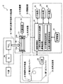
- FIG. 1 is a conceptual diagram of a carbon isotope analyzer.
- FIG. 2 is a conceptual diagram showing an embodiment a of the carbon dioxide isotope generator.
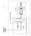
- FIG. 3 is a conceptual diagram showing an embodiment b of the carbon dioxide isotope production apparatus.
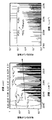
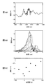
- FIG. 4 is a diagram showing a 4.5 ⁇ m band absorption spectrum of 14 CO 2 and a competitive gas.
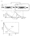
- 5A and 5B are diagrams illustrating the principle of high-speed scanning type cavity ring-down absorption spectroscopy using laser light.
- FIG. 6 is a graph showing the temperature dependence of the absorption amount ⁇ of 13 CO 2 and 14 CO 2 in CRDS.
- FIG. 7 is a conceptual diagram of Modification 1 of the carbon isotope analyzer.
- FIG. 1 is a conceptual diagram of a carbon isotope analyzer.
- FIG. 2 is a conceptual diagram showing an embodiment a of the carbon dioxide isotope generator.
- FIG. 3 is a conceptual diagram showing an embodiment b
- FIG. 8 is a diagram showing the relationship between the absorption wavelength and the absorption intensity of the analysis sample.
- FIG. 9 is a conceptual diagram of a modification of the optical resonator.
- FIG. 10 is a conceptual diagram of Modification 2 of the carbon isotope analyzer.
- FIG. 11 is a conceptual diagram of Modification 3 of the carbon isotope analyzer.
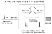
- FIG. 12 is a diagram showing the principle of generating a mid-infrared comb using a single optical fiber.
- FIG. 13 is a conceptual diagram of a modification of the light generator.
- 14A is a diagram showing wavelength shift soliton generation
- FIG. 14B is a diagram showing a spectrum waveform of a mid-infrared comb.
- 15A is a spectrum of SC light, FIG.
- FIG. 15B is a spectrum of mid-infrared light
- FIG. 15C is a diagram showing a relationship between a time difference and a wavelength of mid-infrared light.
- 16A is a spectrum of SC light
- FIG. 16B is a spectrum of mid-infrared light
- FIG. 16C is a diagram showing a relationship between a time difference and a wavelength of mid-infrared light.
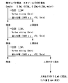
- FIG. 17 is a diagram showing an outline of a processing method when plasma is used as a biological sample.
- FIG. 18 is a diagram showing an outline of a treatment method using a deproteinization method when plasma, urine, or fecal homogenate is used as a biological sample.
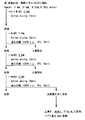
- FIG. 19 is a diagram showing an outline of a treatment method using a liquid-liquid extraction method when plasma, urine, or fecal homogenate is used as a biological sample.
- FIG. 20 is a diagram showing an outline of a treatment method by a solid phase extraction method when plasma, urine, or fecal homogenate is used as a biological sample.
- FIG. 21 is a diagram showing an outline of a processing method using an ultrafiltration method when plasma, urine, or fecal homogenate is used as a biological sample.
- the present invention relates to a combustion unit that generates a gas containing a carbon dioxide isotope from a carbon isotope, a carbon dioxide isotope production device including a carbon dioxide isotope purification unit; an optical resonator having a pair of mirrors, and an optical resonator A spectroscopic device having a photodetector for detecting the intensity of transmitted light from the light source; one light source, an optical path for generating a plurality of lights having different frequencies from the light of the light source, and a plurality of lights having different frequencies by passing through the light And a light generating device including a nonlinear optical crystal that generates light having an absorption wavelength of carbon dioxide isotope from the difference.
- an optical path including a first optical fiber that transmits light from a light source and a second optical fiber for wavelength conversion that branches from the first optical fiber and joins at a confluence on the downstream side of the first optical fiber is used.
- an optical fiber that transmits light from a light source and broadens the spectrum and a spectroscopic unit that divides the light from the light source into a plurality of spectral components and collects a predetermined spectral component on a nonlinear crystal can be used.
- FIG. 1 is a conceptual diagram of a carbon isotope analyzer.
- the carbon isotope analyzer 1 includes a carbon dioxide isotope generator 40, a light generator 20, a spectroscope 10, and a calculation device 30.
- the radioisotope 14 C which is a carbon isotope
- the light having an absorption wavelength of carbon dioxide isotope 14 CO 2 produced from radioisotopes 14 C is a light 4.5 ⁇ m band.
- the “carbon isotope” means the stable carbon isotopes 12 C and 13 C and the radioactive carbon isotope 14 C unless otherwise specified.
- the element symbol “C” when the element symbol “C” is simply displayed, it means a carbon isotope mixture in a natural abundance ratio.
- the stable isotopes of oxygen are 16 O, 17 O and 18 O, but when the element symbol “O” is indicated, it means a mixture of oxygen isotopes at their natural abundance.
- “Carbon dioxide isotope” means 12 CO 2 , 13 CO 2 and 14 CO 2 unless otherwise specified.
- it when simply indicated as “CO 2 ”, it means a carbon dioxide molecule composed of carbon and oxygen isotopes in a natural abundance ratio.
- biological sample means blood, plasma, serum, urine, feces, bile, saliva, other body fluids and secretions, exhaled gas, oral gas, skin gas, other biological gases, and lungs. It means any sample that can be collected from a living body, such as various organs such as heart, liver, kidney, brain, skin, and crushed materials thereof.
- the biological sample may be derived from any organism including animals, plants, and microorganisms, preferably from mammals, and more preferably from humans. Mammals include, but are not limited to, humans, monkeys, mice, rats, guinea pigs, rabbits, sheep, goats, horses, cows, pigs, dogs, cats and the like.
- the carbon dioxide isotope production device 40 can use various devices without particular limitation as long as the carbon isotope can be converted into the carbon dioxide isotope.
- the carbon dioxide isotope generator 40 preferably has a function of oxidizing a sample and converting carbon contained in the sample to carbon dioxide.
- TOC total organic carbon
- sample gas generators for gas chromatography sample gas generators for combustion ion chromatography
- elemental analyzers (EA) elemental analyzers
- G carbon generator
- carbon dioxide generators 40a and 40b as shown in FIGS. FIG.
- Examples of the method for removing CO and N 2 O include a method for collecting and separating 14 CO 2 as follows. Further, the oxidation catalyst or platinum catalyst, CO, a method of removing and reducing the N 2 O, and the combination with the collection and separation methods used.
- FIG. 2 is a conceptual diagram showing an embodiment a of a carbon dioxide isotope production apparatus.
- the carbon dioxide isotope production device 40a includes a combustion unit 42 and a carbon dioxide isotope purification unit 43a.
- the heating unit include an electric furnace such as a tubular electric furnace in which the combustion tube can be disposed inside and the combustion tube can be heated.
- An example of a tubular electric furnace is ARF-30M (Asahi Rika Seisakusho).
- the combustion pipe preferably includes an oxidation part and / or a reduction part filled with at least one kind of catalyst on the downstream side of the carrier gas flow path.
- the oxidation part and / or the reduction part may be provided at one end of the combustion pipe or as a separate member.
- the catalyst filled in the oxidation part include copper oxide and a silver / cobalt oxide mixture.
- H 2 and CO generated by burning the sample are oxidized to H 2 O and CO 2 .
- the catalyst that fills the reducing portion include reduced copper and platinum catalysts.
- nitrogen oxide (NO x ) containing N 2 O is reduced to N 2 .
- a heat desorption column such as that used in gas chromatography (GC) for 14 CO 2 in gas generated by combustion of a biological sample is used. It can. Thereby, the influence of CO and N 2 O can be reduced or eliminated at the stage of detecting 14 CO 2 . Moreover, since the concentration of 14 CO 2 is expected by temporarily collecting CO 2 gas containing 14 CO 2 in the GC column, an improvement in the partial pressure of 14 CO 2 can be expected.
- the separation Figure 3 is re-emission by 14 CO 2 is a conceptual diagram showing an embodiment b of the carbon dioxide isotope production system.
- the carbon dioxide isotope production device 40b includes a combustion unit and a carbon dioxide isotope purification unit.
- the combustion unit can be configured in the same manner as in FIG.
- a 14 CO 2 adsorbent such as soda lime or calcium hydroxide can be used.
- the problem of contaminated gas can be solved by isolating 14 CO 2 in the form of carbonate. Since 14 CO 2 is retained as the carbonate, the sample can be temporarily stored.
- phosphoric acid can be used for re-release. By providing either (i), (ii), or both configurations, the contaminant gas can be removed.
- the spectroscopic device 10 includes an optical resonator 11 and a photodetector 15 that detects the intensity of transmitted light from the optical resonator 11.
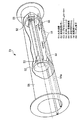
- An optical resonator (Optical resonator or Optical cavity) 11 is disposed so that a cylindrical main body in which a carbon dioxide isotope to be analyzed is sealed, and a concave surface facing one end and the other end in the longitudinal direction inside the main body.
- a pair of mirrors 12a and 12b with high reflectivity (reflectance: 99.99% or more), a piezo element 13 for adjusting the distance between the mirrors 12a and 12b disposed at the other end inside the main body, and a gas to be analyzed are filled.
- pouring a carbon dioxide isotope into the side part of a main body and the atmospheric pressure adjustment port which adjusts the atmospheric pressure in a main body.
- the laser light When laser light is incident and confined inside the optical resonator 11, the laser light repeats multiple reflections on the order of several thousand to 10,000 times while outputting light having an intensity corresponding to the reflectivity of the mirror. Therefore, since the effective optical path extends to several tens of kilometers, a large amount of absorption can be obtained even if the analysis target gas enclosed in the optical resonator is extremely small.
- FIG. 5A and 5B are diagrams showing the principle of high-speed scanning type cavity ring-down absorption spectroscopy (hereinafter also referred to as “CRDS”) using laser light.
- CRDS high-speed scanning type cavity ring-down absorption spectroscopy
- FIG. 5A when the mirror interval satisfies the resonance condition, a high-intensity signal is transmitted from the optical resonator.
- the piezo element 13 is operated to change the mirror interval and the non-resonant condition is set, a signal cannot be detected due to the light interference effect. That is, by quickly changing the optical resonator length from resonance to non-resonance conditions, an exponential decay signal [Ringdown signal] as shown in FIG. 5A can be observed.
- the transmitted time-dependent ring-down signal has a curve as shown by a dotted line in FIG. 5B.
- the optical resonator is filled with a light-absorbing substance, as indicated by the solid line in FIG. 5B, the laser light is absorbed every time it reciprocates in the optical resonator, so that the light attenuation time is shortened.
- the absolute concentration of the absorbing material can be calculated by applying Beer-Lambert's law ii. . Further, by measuring the amount of change in the attenuation factor (ring-down rate) proportional to the absorbing substance concentration in the optical resonator, the absorbing substance concentration in the optical resonator can be measured. After the transmitted light leaking from the optical resonator is detected by the photodetector and the 14 CO 2 concentration is calculated using an arithmetic device, the 14 C concentration can be calculated from the 14 CO 2 concentration. In addition, it is good also as a structure which detects the light of a predetermined wavelength using the diffraction grating 14 with a photodetector (FIG. 10). Details will be described later together with light generation.
- the assumed optical resonator length is 1 mm to 10 m.
- a long optical resonator length is effective in securing the optical path length.
- the optical resonator length is preferably between 10 cm and 60 cm.
- the radii of curvature of the mirrors 12a and 12b are preferably the same as or longer than the optical resonator length.
- the mirror interval can be adjusted on the order of several micrometers to several tens of micrometers, for example, by driving the piezo element 13. In order to create an optimum resonance condition, fine adjustment by the piezo element 13 can be performed.
- the pair of mirrors 12a and 12b has been described with a pair of concave mirrors. However, if a sufficient optical path is obtained, other combinations of concave mirrors and plane mirrors, or combinations of plane mirrors may be used. It does not matter.
- As a material constituting the mirrors 12a and 12b sapphire glass can be used.
- the cell 16 filled with the analysis target gas preferably has a smaller volume. This is because the optical resonance effect can be obtained effectively even with a small number of analysis samples.
- the capacity of the cell 16 can be exemplified as 8 mL to 1000 mL.
- As the cell volume for example, a preferable volume can be selected according to the amount of 14 C source that can be used for measurement, and a cell of 80 mL to 120 mL is suitable for a 14 C source that can be obtained in large quantities such as urine. For a 14 C source with limited availability such as tears, a 8 mL to 12 mL cell is preferred.
- FIG. 6 is a graph showing the temperature dependence of ⁇ due to absorption of 13 CO 2 and 14 CO 2 obtained by calculation.
- 14 C / Total C is 10 ⁇ 10 , 10 ⁇ 11 , and 10 ⁇ 12 .
- the absorption by 13 CO 2 at room temperature of 300 K exceeds or is almost equal to the absorption amount of 14 CO 2. I found it necessary to do it.
- the ring-down rate variation ⁇ 0 to 10 1 s ⁇ 1 which is a noise component derived from the optical resonator, it can be understood that the measurement of 14 C / Total C ratio to 10 ⁇ 11 can be realized.
- ⁇ Light generator> As the light generation device 20, various devices can be used without any particular limitation as long as the device can generate light having an absorption wavelength of carbon dioxide isotope.
- a description will be given by taking as an example a light generator that easily generates light in the 4.5 ⁇ m band, which is the absorption wavelength of the radioactive carbon isotope 14 C, and that has a compact device size.
- the light generator 20 passes one light source 23, a plurality of optical fibers (first optical fiber 21 and second optical fiber 22) that generate light of a plurality of different frequencies from the light source 23, and a plurality of obtained lights.
- a nonlinear optical crystal 25 that generates light having an absorption wavelength of carbon dioxide isotope from a difference in light frequency.
- the light source 23 it is preferable to use a short-wavelength pulse wave generator. This is because when a short-wavelength pulse wave generator is used as the light source 23, a comb-like light bundle (hereinafter also referred to as “optical comb”) having an equal wavelength width of each wavelength is obtained. When a continuous wave generator is used as the light source, the wavelength width of the light at the center of the light bundle becomes thick, so that a comb-like light bundle with a uniform wavelength width cannot be obtained.
- a solid laser, a semiconductor laser, or a fiber laser that outputs a short pulse by mode synchronization can be used. Among these, it is preferable to use a fiber laser.
- the fiber laser is a practical light source that is compact and excellent in environmental stability.
- an erbium (Er) -based (1.55 ⁇ m band) or ytterbium (Yb) -based (1.04 ⁇ m band) fiber laser can be used. From an economical viewpoint, it is preferable to use a widely used Er fiber laser, and from the viewpoint of increasing the light absorption intensity, it is preferable to use a Yb fiber laser.
- a first optical fiber 21 that transmits light from a light source, and a second optical fiber 22 for wavelength conversion that is branched from the first optical fiber 21 and merges on the downstream side of the first optical fiber 21.
- the 1st optical fiber 21 what is connected from the light source to the optical resonator can be used.
- the other end on the downstream side of the first optical fiber 21 is preferably in contact with the mirror 12a. This is because by preventing the transmitted light from the optical resonator 11 from coming into contact with air, the accuracy of the intensity measurement of the transmitted light can be increased.
- the material is preferably a fiber made of fused silica.
- the second optical fiber 22 it is preferable to use an optical fiber having anomalous dispersion characteristics and capable of efficiently generating an ultrashort pulse on a desired long wavelength side by stimulated Raman scattering and a soliton effect. Specific examples include a polarization maintaining fiber, a single mode fiber, a photonic crystal fiber, and a photonic band gap fiber. It is preferable to use an optical fiber having a length of several meters to several hundred meters in accordance with the wavelength shift amount.
- the material is preferably a fiber made of fused silica.
- nonlinear optical crystal 25 for example, a PPMGLSLT (periodically poled MgO-doped Stoichiometric Lithium Tantalate (LiTaO 3 )) crystal, a PPLN (periodically poled Lithium Niobate) crystal, or a GaSe (Gallium selenide) crystal can be used. This is because light in the 4.5 ⁇ m band is likely to be generated. Moreover, since one fiber laser light source is used, the fluctuation of the optical frequency can be canceled in the difference frequency mixing as described later.
- difference frequency generation a plurality of light beams having different wavelengths (frequencies) transmitted by the first and second optical fibers 21 and 22 are passed through the nonlinear optical crystal.
- Difference frequency light can be obtained from the frequency difference. That is, by generating two lights having wavelengths ⁇ 1 and ⁇ 2 from one light source 23 and passing the two lights through the nonlinear optical crystal, the absorption wavelength of the carbon dioxide isotope is obtained from the difference in frequency. Light in the 4.5 ⁇ m band can be generated.
- the conversion efficiency of DFG using a nonlinear optical crystal depends on the photon density of a light source having a plurality of wavelengths ( ⁇ 1 , ⁇ 2 ,... ⁇ x ).
- the light of a difference frequency can be generated from one pulse laser light source by DFG.
- f r mode
- Frequency f f ceo + N ⁇ f r, N: Mode Number
- Non-Patent Document 1 In the case of a carbon isotope analyzer devised by I. Galli et al.
- Non-Patent Document 1 two types of laser devices having different wavelengths are prepared, and the absorption wavelength of carbon dioxide isotope is obtained from the difference in the frequency of laser light. Irradiation light was generated. Therefore, the apparatus is large and the operation is complicated. Moreover, since light is generated from the two light sources, the fluctuation width and fluctuation timing of the two lights are different from each other, and it is difficult to suppress the fluctuation of the light when the two lights are mixed. Therefore, a control device that controls the fluctuation of light has been required.
- the light generation apparatus is composed of one fiber laser light source, several m of optical fiber, and nonlinear optical crystal, so it is compact and easy to carry and easy to operate. .
- the fluctuation width and the fluctuation timing of each light are the same. Therefore, the fluctuation of the optical frequency can be easily canceled by performing the difference frequency mixing without using the control device.
- An optical system for transmitting laser light into the air on the optical path between the confluence of the first optical fiber and the second optical fiber and an optical system for condensing and / or expanding the laser light by a lens as necessary May be constructed.
- the light may be transmitted through space or may be transmitted using an optical fiber, and may take various forms.
- the arithmetic unit 30 is not particularly limited as long as it can measure the concentration of the absorbing substance in the optical resonator from the above-described decay time and ring-down rate, and can measure the carbon isotope concentration from the absorbing substance concentration.
- An apparatus can be used.
- the arithmetic control unit 31 may be configured by arithmetic means used in a normal computer system such as a CPU.
- Examples of the input device 32 include a pointing device such as a keyboard and a mouse.
- Examples of the display device 33 include an image display device such as a liquid crystal display and a monitor.
- Examples of the output device 34 include a printer.
- a storage device such as a ROM, a RAM, or a magnetic disk can be used.
- a cooling and dehumidifying device may be provided. It may be dehumidified by a cooling means such as a Peltier element, or may be dehumidified by a membrane separation method using a water vapor removing polymer membrane such as a fluorine ion exchange resin membrane. These will be described in the later-described modification and analysis method columns.
- the detection sensitivity for the radioactive carbon isotope 14 C is assumed to be about “0.1 dpm / ml”.
- the detection sensitivity “0.1 dpm / ml” it is not sufficient to use a “narrow band laser” as a light source, and the stability of the wavelength (frequency) of the light source is required. That is, it is a requirement that the wavelength of the absorption line does not deviate and that the line width is narrow.
- the carbon isotope analyzer 1 can solve this problem by using a stable light source using “optical frequency comb light” for CRDS.
- the carbon isotope analyzer has been described with reference to the embodiment.
- the carbon isotope analyzer is not limited to the apparatus according to the above-described embodiment, and various modifications can be made.
- modifications of the carbon isotope analyzer will be described focusing on the changes.
- FIG. 7 is a conceptual diagram of Modification 1 of the carbon isotope analyzer.
- the spectroscopic device 1 a may further include a Peltier element 19 that cools the optical resonator 11 and a vacuum device 18 that houses the optical resonator 11. Since the light absorption of 14 CO 2 has temperature dependency, by reducing the set temperature in the optical resonator 11 by the Peltier element 19, the absorption line of 14 CO 2 and the absorption lines of 13 CO 2 and 12 CO 2 This is because it is easy to distinguish between the two , and the absorption intensity of 14 CO 2 is increased.
- the optical resonator 11 is arranged in the vacuum device 18 to prevent the optical resonator 11 from being exposed to the outside air and to reduce the influence of the external temperature, thereby improving the analysis accuracy.
- a cooling device for cooling the optical resonator 11 in addition to the Peltier element 19, for example, a liquid nitrogen tank, a dry ice tank, or the like can be used. From the viewpoint of reducing the size of the spectroscopic device 11, it is preferable to use the Peltier element 19, and from the viewpoint of reducing the manufacturing cost of the device, it is preferable to use a liquid nitrogen water tank or a dry ice tank.
- the vacuum device 18 is not particularly limited as long as it can accommodate the optical resonator 11 and can irradiate the light emitted from the light generator 20 into the optical resonator 11 and transmit the transmitted light to the photodetector.
- Various vacuum devices can be used.
- FIG. 8 (cited from Applied Physics Vol.24, pp.381-386, 1981) shows the absorption wavelengths of the analytical samples 12 C 16 O 2 , 13 C 18 O 2 , 13 C 16 O 2 , and 14 C 16 O 2. The relationship of absorption intensity is shown.
- carbon dioxide containing each carbon isotope has a specific absorption line. In actual absorption, each absorption line has a finite width due to the spread caused by the pressure and temperature of the sample. For this reason, it is preferable that the pressure of a sample is below atmospheric pressure, and temperature is 273 K (0 degreeC) or less.
- the absorption intensity of 14 CO 2 has temperature dependence, it is preferable to set the set temperature in the optical resonator 11 as low as possible.
- the specific set temperature in the optical resonator 11 is preferably 273 K (0 ° C.) or less.
- the lower limit is not particularly limited, but it is preferable to cool to about 173 K to 253 K ( ⁇ 100 ° C. to ⁇ 20 ° C.), particularly about 233 K ( ⁇ 40 ° C.), from the viewpoint of cooling effect and economy.
- the spectroscopic device may further include vibration absorbing means. This is because it is possible to prevent the mirror interval from shifting due to vibration from the outside of the spectroscopic device and to increase the measurement accuracy.
- vibration absorbing means for example, a shock absorber (polymer gel) or a seismic isolation device can be used.
- a seismic isolation device it is possible to use a device that can give the spectroscopic device a vibration in the opposite phase of the external vibration.
- FIG. 9 a conceptual diagram (partially cutaway view) of a specific mode of the optical resonator is shown in FIG.
- the optical resonator 51 is disposed in a cylindrical heat insulation chamber 58 as a vacuum device, a measurement gas cell 56 disposed in the heat insulation chamber 58, and both ends of the measurement gas cell 56.
- the pair of high reflectivity mirrors 52, the mirror drive mechanism 55 disposed at one end of the measurement gas cell 56, the ring piezo actuator 53 disposed at the other end of the measurement gas cell 56, and the measurement gas cell 56 are cooled.
- a water cooling heat sink 54 having a cooling pipe 54a connected to a circulating cooler (not shown).
- the adjustment of the mirror interval by the piezo element 13 is used in the spectroscopic device 10 as the ring-down signal acquisition unit.
- the optical resonator in the light generation device 20 is used. It is good also as a structure which provides the light-blocking apparatus which interrupts
- the light blocking device various devices can be used without particular limitation as long as the device can quickly block the light having the absorption wavelength of carbon dioxide isotope, and an optical switch 26 as shown in FIG. 7 can be exemplified. . It should be noted that it is necessary to block light sufficiently faster than the light decay time in the optical resonator.
- the first optical fiber 21 is connected from the light source 23 to the optical resonator 11.
- the first optical fiber 21 may include a first optical fiber 21 a connected from the light source 23 to the nonlinear optical crystal 25, and a mid-infrared first optical fiber 21 b connected from the nonlinear optical crystal 25 to the optical resonator 11. .
- the first optical fiber 21b the light in the 4.5 ⁇ m band obtained through the nonlinear optical crystal can be transmitted to the optical resonator 11 with efficiency.
- the 1st optical fiber 21a the fiber similar to the above-mentioned 1st optical fiber 21 can be used.
- the first optical fiber 21b various optical fibers can be used without particular limitation as long as it is a mid-infrared optical fiber that hardly absorbs light in the 4.5 ⁇ m band, and it is preferable to use a fluoride fiber or a hollow fiber.
- the light generation device 20 may include an optical transmission device that transmits light from the nonlinear optical crystal 25 to the optical resonator 11 instead of the first optical fiber 21b illustrated in FIG.
- the optical transmission device one or more optical lenses can be exemplified, and an optical path in which the optical lenses are arranged upstream, downstream, or both of the nonlinear optical crystal, and an optical device obtained by modularizing them can be used.
- FIG. 10 is a conceptual diagram of Modification 2 of the carbon isotope analyzer.
- the spectroscopic device 1 d may further include a diffraction grating 14 that splits transmitted light.
- a photodetector is provided with the photodetector 15a and the photodetector 15b which detect the transmitted light of a respectively different wavelength. This is because the measurement accuracy can be improved by analyzing each of the transmitted light having different spectral wavelengths.
- a predetermined light is selected using an optical resonator, a diffraction grating is installed after passing, and further wavelength selection is performed to obtain the transmitted light intensity of only the necessary absorption line, and the 14 C concentration in the measurement sample gas. May be measured. This is because installing the diffraction grating improves the analytical performance.
- FIG. 11 is a conceptual diagram of Modification 3 of the carbon isotope analyzer.
- FIG. 12 is a diagram showing the principle of generating a mid-infrared comb using a single optical fiber. The carbon isotope analyzer 1e of FIG.
- FIG. 11 includes a delay line 28 composed of a plurality of wavelength filters between the light source 23 and the nonlinear optical crystal 25.
- the light from the light source 23 is transmitted by the first optical fiber 21 and the spectrum is expanded (expansion of spectrum).
- the spectral components are shifted in time, as shown in FIG. 12, the spectral components are separated by the delay line 28 (optical path difference adjuster), and the time difference is adjusted.
- a mid-infrared comb can be generated by focusing on the nonlinear crystal 25.
- the delay line was mentioned as a spectroscopic means, it is not limited to it, You may use a dispersion medium.
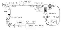
- FIG. 13 shows a modification of the light generator.
- a plurality of light beams are generated using a photonic crystal fiber (hereinafter also referred to as “PCF”) that generates broadband light (supercontinuum (hereinafter also referred to as “SC”)) and a wavelength filter (or wavelength splitter).
- PCF photonic crystal fiber
- SC broadband light
- SC wavelength filter
- a time difference between the spectral components is adjusted, a delay line for condensing a predetermined spectral component on the nonlinear crystal, a nonlinear crystal (PPMGSLT crystal) that forms mid-infrared comb light, and a spectroscope With.
- a delay line optical path difference adjuster
- SC light and mid-infrared comb light were generated using a 1.014 ⁇ m band ultrashort pulse fiber laser light source.
- the experimental condition was a Yb-doped fiber laser having a repetition rate of 184 MHz, which was mode-locked by nonlinear polarization rotation, as a light source.
- the pulse of the light source was amplified in a Yb-doped double clad fiber with a high power pump laser diode capable of providing 8 W output.
- the amplified pulses were highly chirped with a center wavelength of 1040 nm and an average power of 3 W, and then compressed to 200 femtoseconds (FWHM) by a diffraction grating pair.
- SC light was extended from 900 nm to 1200 nm, which can be supported by difference frequency mixing (DFG) in the mid-infrared region.
- DFG difference frequency mixing
- two signals of 900 nm to 1000 nm and 1000 nm to 1200 nm, each of which overlaps space and time, are collected in a nonlinear optical crystal that enables DFG to 4.5 ⁇ m. I let it light. In that case, it experimented using PCF provided with a different dispersion characteristic.
- Example 1 A photonic crystal fiber (manufactured by NKT Photonics) 20 cm, which is PCF having a zero dispersion wavelength of 1005 nm, was used, and after adjusting the time difference between the two components using a delay line, it was condensed on a GaSe crystal. The obtained results are shown in FIGS. 14A and 14B.
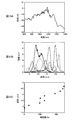
- FIG. 15A to FIG. 15C show the experimental results of focusing on a PPMgSLT crystal using 20 cm of an all normal dispersion photonic crystal fiber (manufactured by NKT Photonics), which is a PCF having a normal dispersion at 1040 nm.
- NKT Photonics manufactured by NKT Photonics
- FIG. 15A shows the SC spectrum.
- 15C shows the relationship between the time difference of the delay line and the spectrum obtained by difference frequency mixing (DFG). Since the SC was generated by normal dispersion PCF, the center wavelength increased monotonically according to the relative time difference. The average power adjusted from the mechanism was on the order of 100 ⁇ W. In order to increase the output, the SC extended by PCF had to be high enough at a specific wavelength to cause DFG.
- DFG difference frequency mixing
- FIG. 16A to FIG. 16C show the experimental results of focusing on a PPMgSLT crystal using a 20 cm photonic crystal fiber (manufactured by NKT Photonics), which is PCF having a zero dispersion wavelength of 1040 nm.
- NKT Photonics manufactured by NKT Photonics
- FIG. 16A there was a peak at a wavelength of 950 nm that is involved in obtaining a high output in the mid-infrared.
- a maximum output of 1.12 mW was measured at a wavelength of 3.9 ⁇ W.
- 16B and 16C show the relationship between the time difference and the wavelength obtained by difference frequency mixing (DFG). There was no linear relationship between the center wavelength and the time difference because the SC pulse was no longer chirped linearly. Despite adjusting the time difference from the long range, the spectrum could not be clearly distinguished. However, since the pulse width was narrow, high output mid-infrared light was obtained.
- DFG difference frequency mixing
- the dehumidifying condition is preferably such that when the CRDS analysis cell is cooled to ⁇ 40 ° C. or lower (233 K or lower), the gas condition (water content) does not cause condensation or freezing under that temperature condition.
- a hygroscopic agent or a gas dryer in the carbon dioxide generation unit (sample introduction unit).
- the hygroscopic agent for example, CaH 2 , CaSO 4, Mg (ClO 4 ) 2 , molecular sieve, H 2 SO 4 , Sicacide, phosphorus pentoxide, Sicapent (registered trademark) or silica gel is used. Can do.
- phosphorus pentoxide Cicapent (registered trademark), CaH 2 , Mg (ClO 4 ) 2 or molecular sieve are preferable, and Cicapent (registered trademark) is more preferable.
- the gas dryer Nafion (registered trademark) dryers (Nafion dryers: manufactured by Perma Pure Inc.) are preferable.
- the hygroscopic agent and the gas dryer may be used alone or in combination.
- the “gas condition that does not condense / freeze under that temperature condition (water content)” was confirmed by measuring the dew point. In other words, it is preferable to be able to dehumidify so that the dew point is ⁇ 40 ° C. or lower (233 K or lower).
- the display of the dew point may be an instantaneous dew point or an average dew point per unit time.
- the dew point can be measured using a commercially available dew point sensor.
- Zentor dew point sensor HTF Al2O3 registered trademark
- Vaisala DRYCAP registered trademark
- DM70 handy type dew point meter Vaisala
- the carrier gas when using the organic element analyzer is preferably a gas containing at least carbon, nitrogen and sulfur elements as much as possible, and helium gas (He) can be exemplified.
- the flow rate of the carrier gas is preferably in the range of 50 mL / min to 500 mL / min, and more preferably in the range of 100 mL / min to 300 mL / min.
- the performance and size of the carbon isotope analyzer according to the embodiment are generally as follows. Detection sensitivity for 14 C as a 14 C analyzer 0.1 dpm / mL Measurement throughput: 400 samples / day, Device size: 2 m ⁇ 1 m ⁇ 1 m or less. On the other hand, LSC performance and size are generally as follows. Detection sensitivity for 14 C: 10 dpm / mL Measurement throughput: 400 samples / day, Device size: 1 m ⁇ 1 m ⁇ 0.5 m. The AMS performance and size are generally as follows. Detection sensitivity for 14 C: 0.001 dpm / mL Measurement throughput: 5 samples / day, Device size: about 15 m ⁇ 10 m ⁇ 3 m.
- the pretreatment of the biological sample broadly includes a biological carbon source removal step and a contaminated gas removal (separation) step.
- the biological source carbon source removal step will be mainly described.
- a biological sample for example, blood, plasma, urine, feces, bile, etc.
- a trace amount of 14 C-labeled compound is analyzed. Therefore, in order to increase the analysis efficiency, it is preferable to perform pretreatment of the biological sample.
- the nature of the CRDS apparatus since the ratio of the 14 C and the total carbon in the biological sample (14 C / Total C) is one of the factors that determine the sensitivity of the measurement, a carbon source derived from a living organism from a biological sample It is preferable to remove.
- the deproteinization rate is about 40% for methanol (MeOH) and about 80% for acetonitrile (MeCN or ACN), and the result is a highly efficient removal of biological carbon sources. It was. Assuming that it was treated with acetonitrile, the 14 C / Total C ratio after the organic solvent extraction to dryness was calculated. As a result, it was considered that an improvement of up to about 40 times can be expected as shown in Table 3. Similar results were obtained in urine. In this case, it was presumed that 0.7 to 10 mgC was obtained from 1 mL of human plasma as the amount of carbon introduced into the CRDS apparatus.
- a pretreatment method for reducing carbon import and concentrating 14 C was studied.
- the target value for 14 C concentration was set to 10 ⁇ 11 or more as the 14 C / Total C ratio.
- a biological carbon source removal step and an organic solvent removal step (drying) were performed, and the 14 C recovery rate and the carbon removal rate were calculated.
- Table 4 shows the 14 C recovery
- Table 5 shows the carbon removal rate.
- a biological carbon source removal process protein removal, liquid-liquid extraction, solid phase extraction, and ultrafiltration were compared.
- FIG. 18 shows the protein removal method
- FIG. 19 shows the liquid-liquid extraction method
- FIG. 20 shows the solid phase extraction method
- FIG. 21 shows the ultrafiltration method.
- 14 C source 14 C-labeled acetaminophen was used.
- the solid phase used for the pretreatment can be appropriately changed according to the compound to be the 14 C source.
- 14 C / Total C ratio when using solid-phase extraction method (Tozuka et al., “Microdose Study of 14C-Acetaminophen With Accelerator Mass Spectrometry to Examine Pharmacokinetics of Parent Drug.nd Metabolites in Healthy Subjects” Clinical Pharmacology & Therapeutics 88, 824, 2010), the 14 C / Total C ratio in human plasma and human urine samples was 10-11 or more.
- EA measurement condition 1 (CNS mode)> Combustion temperature: 1150 ° C (maximum instantaneous 1800 ° C) Reduction temperature: 760 ° C Carrier gas: He Flow rate: 200mL / min Oxygen supply amount: 70-80 seconds at 30 mL / min Oxidation catalyst: Cobalt oxide Reduction catalyst: Reduced copper Halogen removal catalyst: Silver Dehumidifier: Cikapent (manufactured by Merk Millipore)
- CN mode 2 Combustion temperature: 950 ° C (momentary maximum 1800 ° C) Reduction temperature: 600 ° C Carrier gas: He Flow rate: 200mL / min Oxygen supply amount: 70-80 seconds at 30 mL / min
- Oxidation catalyst Copper oxide reduction catalyst: Reduced
- Example 1 Combustion of solid sample The sample was burned (oxidized) using EA, and it was confirmed from the obtained chromatogram whether CO 2 could be separated and measured. The carbon ratio (carbon content of each sample) was calculated from the area value obtained from the chromatogram, and the degree of combustion (combustion rate) was examined.
- Each element of C, N, and S contained in the sample becomes an oxide by combustion (however, NO X is reduced to N 2 ), separated by a thermal desorption column, and then separated by a TCD (Thermal Conductivity Detector). Each element was detected as CO 2 , N 2 , and SO 2 gas. Table 8 shows the C ratio (%) calculated using the peak area value of the obtained chromatogram.
- the difference (absolute value) between the theoretical C ratio (%) and the calculated C ratio (%) is 0 for sulfanilamide. 1%, glucose 0.2%, methionine 0.4%, and flame retardant graphite 2.0%. As a result, it was considered that 98.0% or more of all the samples including graphite, which is a flame retardant material, was burned (oxidized).
- a glucose aqueous solution was prepared as shown in Table 10 so as to have a moisture content of 10, 20, 50 ⁇ L and a carbon content of 0.01 to 2.0 mgC, was encapsulated in a tin capsule, and measured under EA measurement condition 1.
- Table 11 shows a plot of carbon amount and peak area value under EA measurement condition 1, a regression equation, and a slope ratio.
- the combustion rate was compared with the slope of the obtained regression equation.
- the slope of the solid sample glucose was 100%, the slope ratio when containing 50 ⁇ L of water was 96.1%. From this, it was considered that 95% or more of the water was burned even at a water content of 50 ⁇ L. Further, at this time, since the combustion rate and the carbon dioxide gasification rate are considered to be equivalent, it was determined that a carbon dioxide gasification rate of 90% or more was achieved when the water content was in the range of 10 to 50 ⁇ L.
- the variation coefficient (CV) is 0.2 to 6.0%
- the relative error (RE) is -2.5 to 5.1%
- the determination coefficient is in the range of the introduced sample dose of 0.1 to 10 mgC.
- R 2 square of correlation coefficient R
- the coefficient of variation (CV) is 0.6 to 2.5%
- the relative error (RE) is 9.4 to 5.1%
- the coefficient of determination is in the range of the introduced sample dose of 0.05 to 10 mgC. indicates: (R 2 correlation coefficient squared R) 0.9999, it was confirmed that the dynamic range 200 times.
- the coefficient of determination was 0.9996 or more for both plasma and urine, and good linearity was confirmed according to the sample amount. It was confirmed that there was no problem in the chromatogram and that the untreated biological sample could be combusted. At this time, when the amount of carbon in the biological sample was calculated from the measurement result of the introduction amount of 50 ⁇ L, it was as shown in Table 18.
- the amount of 14 C introduced was constant, and the total C amount was changed to perform measurement. As a result it was confirmed that the C amount 14.1mgC even 14 C recovery rate of 90% or more. From the above, it was considered that almost all 14 C in the compound was 14 CO 2, and the 14 C recovery rate was considered to be 90% or more with the carbon dioxide gasification rate.
- a pretreatment method in AMS which is a representative example of radiocarbon isotope measurement prior to the present invention, is given.
- a pretreatment method in the case of using the principle shown in FIG. Compare as The pretreatment method in AMS includes adjustments such as cleaning and dilution of the measurement sample, carbon dioxide conversion of the biological sample after the pretreatment, reduction step, and press step.
- AMS requires 2 people and the minimum number of days is 6-7 days.
- the measurement cost is 4 million yen. (40,000 yen per sample, refer to the data from the accelerator analysis center).
- the pretreatment method using CRDS of the present application includes a step of removing biological carbon from a biological sample, a step of carbonizing the biological sample after the pretreatment, a purification (concentration, contamination gas removal) step, and a dehumidification cooling step. Consists of. When 100 specimens are measured, since the process of carbonizing a biological sample can be automated, one person can process in 1-2 days. The measurement cost is assumed to be 1 million yen or less. (Set hundreds to thousands of specimens) The equipment using AMS requires a special building with an installation area of about one half of the tennis court, but the equipment using CRDS can reduce the installation area to the desktop size and increase the degree of freedom of arrangement. Can do.
- pretreatment methods in LSC and AMS which are representative examples of radiocarbon isotope measurement prior to the present invention, are given.
- a pretreatment method in the case where the principle shown in FIG. are compared as an example.
- the pretreatment process for measuring a biological sample with LSC takes several minutes to about 28 hours, although the treatment time varies depending on the type of biological sample.
- pretreatment methods for urine and blood When urine is subjected to LSC measurement, a urine sample may be diluted with distilled water as necessary. The time required for the pretreatment is several minutes.
- LSC detects the radiation emitted from the sample and the fluorescence emitted by the scintillator and measures the radiation dose.
- a tissue lysing agent such as Soluene-350 (PerkinElmer)
- Soluene-350 PerkinElmer
- Another pretreatment method includes a method of drying a blood sample, burning and oxidizing carbon in the sample to carbon dioxide, and trapping the generated carbon dioxide with an amine or the like. The time required for the pretreatment is about 4 to 24 hours.
- the pretreatment process in the case of measuring a biological sample by AMS includes a first process to a fifth process.
- the outline of each process is described below.
- biological samples include blood, plasma, urine, feces, bile and the like.
- the first step is a step of diluting a biological sample to be measured with a dilution solvent as necessary. As a dilution solvent, ultrapure water or a blank sample is preferably used.
- the second step is a step in which the sample collected is oxidized to convert carbon contained in the sample into carbon dioxide.
- the third step is a step of isolating and purifying carbon dioxide from water or nitrogen. The amount of carbon in the purified carbon dioxide is quantified.
- the fourth step is a step of converting purified carbon dioxide into a graphite by a reduction reaction.
- the reduction reaction there is a method in which iron powder as a reducing agent and hydrogen gas are mixed and heated in an electric furnace to produce graphite.
- the fifth step is a step of pressing the prepared graphite.
- the time required for the pretreatment step is about 6 days.
- the time required for the process is from several minutes to about 28 hours.
- Examples of pretreatment include dilution, extraction, and concentration. In principle, it is sufficient that the carbon contained in the sample to be measured is completely burned and converted to carbon dioxide, and according to this embodiment, the pretreatment time can be shortened from several minutes to about 1.5 hours per specimen. .
- the tissue lysis process and the decolorization process required when measuring a blood sample by LSC are not required when measuring by CRDS. Therefore, the time required for the pretreatment step shown in FIGS. 18 to 21 is several minutes to about 1.5 hours per specimen.
- the radioisotope 14 C will be described as an example of analysis.
- a carbon isotope analyzer 1 as shown in FIG. 1 is prepared.
- a radioactive isotope 14 C source a biological sample containing 14 C, such as blood, plasma, urine, feces, bile, etc., is prepared.
- the biological carbon source is removed by deproteinization as a pretreatment of the biological sample.
- the protein removal method include a protein removal method in which the protein is insolubilized with an acid or an organic solvent, a protein removal method using ultrafiltration or dialysis utilizing a difference in molecular size, a protein removal method using solid phase extraction, and the like.
- the 14 C-labeled compound can be extracted and the organic solvent itself can be easily removed, so that the protein removal method using an organic solvent is preferable.
- an organic solvent is first added to a biological sample to insolubilize the protein.
- the 14 C-labeled compound adsorbed on the protein is extracted into the organic solvent-containing solution.
- the organic solvent-containing solution may be collected in a separate container, and then an organic solvent may be further added to the residue and extracted. The extraction operation may be repeated a plurality of times.
- the biological sample when the biological sample is feces, organs such as lungs, etc., in a form that is difficult to uniformly mix with the organic solvent, the biological sample and the organic solvent are mixed uniformly, such as by homogenizing the biological sample. It is preferable to carry out a process to be performed. Moreover, you may remove the insolubilized protein by centrifugation operation, filtration with a filter, etc. as needed. Thereafter, the organic solvent is evaporated to dry the extract containing the 14 C-labeled compound, and the carbon source derived from the organic solvent is removed.
- the organic solvent is preferably methanol (MeOH), ethanol (EtOH), or acetonitrile (ACN), and more preferably acetonitrile.
- the pretreated biological sample is heated and burned to generate a gas containing carbon dioxide isotope 14 CO 2 from the radioactive isotope 14 C source. Then, N 2 O and CO are removed from the obtained gas. Specifically, it is preferable to separate 14 CO 2 using the apparatus shown in FIGS.
- the 14 CO 2 or passed over drying agent such as calcium carbonate it is preferred to remove water by condensation of moisture by cooling the 14 CO 2. This is because a decrease in mirror reflectivity due to icing / frosting of the optical resonator 11 caused by moisture contained in 14 CO 2 lowers the detection sensitivity, so that the analysis accuracy is improved by removing moisture.
- (E) 14 CO 2 is filled in an optical resonator 11 having a pair of mirrors 12a and 12b as shown in FIG. And it is preferable to cool the 14 CO 2 below 273K (0 °C). This is because the absorption intensity of irradiation light is increased. It is preferable to keep the optical resonator 11 in a vacuum atmosphere. This is because the measurement accuracy is improved by reducing the influence of the external temperature.
- Optical frequency comb light is generated as the first light from one light source 23.
- the obtained first light is transmitted to the first optical fiber 21.
- the first light is transmitted to the second optical fiber 22 for wavelength conversion branched from the first optical fiber 21 to generate the second light having a wavelength different from that of the first light.
- the second light is combined on the downstream side of the first optical fiber 21, the first light and the second light are passed through the nonlinear optical crystal 25, and the absorption wavelength of the carbon dioxide isotope 14 CO 2 is 4. 5 ⁇ m band light is generated as irradiation light.
- the carbon dioxide isotope 14 CO 2 is irradiated with irradiation light to resonate.
- the intensity of the transmitted light from the optical resonator 11 is measured. As shown in FIG. 5, the transmitted light may be dispersed and the intensity of each of the separated transmitted light may be measured.
- the radioisotope 14 C has been mainly described as the carbon isotope to be analyzed.
- the radioactive isotope 14 C, 12 C and 13 C which are stable isotopes can be analyzed.
- the mirror interval is preferably 10 to 60 cm, and the radius of curvature of the mirror is preferably equal to or greater than the mirror interval.
- the radioisotope 14 C has a lower natural abundance ratio than the stable isotope elements 12 C and 13 C. 14 C makes it possible to observe various reaction processes by increasing its concentration by artificial manipulation and measuring it with high accuracy.
- the carbon isotope analyzer according to the embodiment may further include a third optical fiber composed of a nonlinear fiber that branches from the first optical fiber and joins the first optical fiber downstream from the branch point. This is because by combining the first to third optical fibers, it is possible to generate two or more kinds of light of various frequencies.
- a medical diagnostic apparatus and an environmental measurement apparatus that partially include the configuration described in the embodiment can be manufactured in the same manner.
- the light generation device described in the embodiment can be used as a measurement device.
- the present invention naturally includes various embodiments not described herein. Therefore, the technical scope of the present invention is defined only by the invention specifying matters according to the scope of claims reasonable from the above description.
Landscapes
- Physics & Mathematics (AREA)
- General Physics & Mathematics (AREA)
- Nonlinear Science (AREA)
- Spectroscopy & Molecular Physics (AREA)
- Chemical & Material Sciences (AREA)
- Analytical Chemistry (AREA)
- General Health & Medical Sciences (AREA)
- Biochemistry (AREA)
- Immunology (AREA)
- Pathology (AREA)
- Life Sciences & Earth Sciences (AREA)
- Health & Medical Sciences (AREA)
- Optics & Photonics (AREA)
- Crystallography & Structural Chemistry (AREA)
- Investigating Or Analysing Materials By Optical Means (AREA)
- Optical Modulation, Optical Deflection, Nonlinear Optics, Optical Demodulation, Optical Logic Elements (AREA)
Abstract
Description
LSCは、テーブルトップサイズの比較的小型な装置であるため簡便かつ迅速な分析が可能であるが、14Cの検出限界濃度が10dpm/mLと高いため臨床試験での使用に耐えうるものではなかった。一方、AMSは14Cの検出限界濃度が0.001dpm/mLと低く、LSCの14Cの検出限界濃度の1000倍以上低いため臨床試験での使用に耐えうるが、装置が大きくしかも高額であるためその利用が制限されていた。例えば日本国内にはAMSは十数台しか設置されていないことより、試料分析の順番待の時間を考慮すると、1サンプルの分析に1週間程度の時間を要していた。そのため、簡易、かつ迅速な14Cの分析法の開発が望まれていた。 Conventionally proposed 14 C analysis methods include liquid scintillation counting (hereinafter also referred to as “LSC”) and accelerator mass spectrometry (hereinafter also referred to as “AMS”). Is mentioned.
LSC is a tabletop-sized device that is relatively small and can be easily and quickly analyzed. However, the detection limit concentration of 14 C is as high as 10 dpm / mL, so it cannot be used in clinical trials. It was. Meanwhile, AMS has a low detection limit concentration of 14 C and 0.001dpm / mL, but can withstand use in clinical trials for more than 1000 times lower detection limit concentrations of 14 C of the LSC, apparatus is large yet high Therefore, its use was restricted. For example, since only a dozen AMSs are installed in Japan, it takes about one week to analyze one sample in consideration of the waiting time for sample analysis. Therefore, development of a simple and rapid 14 C analysis method has been desired.
例えば非特許文献1では、I. Galliらにより、キャビティーリングダウン分光法(Cavity Ring-Down Spectroscopy、以下「CRDS」ともいう)による天然同位体存在比レベルの14C分析の実証がなされ、その可能性が注目された。
しかしながら、CRDSによる14C分析が実証されたものの、利用された4.5μm帯レーザー光発生装置は極めて複雑な構造であった。そのため、より簡易で使い勝手のよい14Cの分析装置及び分析方法が求められていた。
以上より、本発明は簡易で使い易く14C分析可能な炭素同位体分析装置及び分析方法を提供することを課題とする。 Several techniques have been proposed as means for solving the above-described problems (for example, see Non-Patent
For example, in
However, although 14 C analysis by CRDS has been demonstrated, the 4.5 μm band laser beam generator used has an extremely complicated structure. Therefore, a simpler and easier-to-use 14 C analyzer and analysis method have been demanded.
In view of the above, an object of the present invention is to provide a carbon isotope analyzer and an analysis method that are simple, easy to use and capable of 14 C analysis.
〈1〉炭素同位体から二酸化炭素同位体を含むガスを生成する燃焼部、二酸化炭素同位体精製部を備える二酸化炭素同位体生成装置と、1対のミラーを有する光共振器、光共振器からの透過光の強度を検出する光検出器を備える分光装置と、1つの光源、光源からの光を伝送する第1光ファイバー、第1光ファイバーから分岐し第1光ファイバーの下流側の合流点で合流する波長変換用の第2光ファイバー、周波数が異なる複数の光を通過させることで周波数の差から二酸化炭素同位体の吸収波長の光を発生させる非線形光学結晶を備える光発生装置と、を備える炭素同位体分析装置。
〈2〉二酸化炭素同位体精製部は、夾雑ガス分離部、二酸化炭素同位体の濃縮部の少なくとも一方を備える〈1〉記載の炭素同位体分析装置。
〈3〉炭素同位体は放射性炭素同位体14Cであり、二酸化炭素同位体は放射性二酸化炭素同位体14CO2である〈1〉または〈2〉に記載の炭素同位体分析装置。
〈4〉光源は、光周波数コム光を発生する〈1〉~〈3〉に記載の炭素同位体分析装置。
〈5〉光源は、ファイバーレーザーである〈1〉~〈4〉のいずれか1つに記載の炭素同位体分析装置。
〈6〉二酸化炭素同位体の吸収波長を有する光は、4.5μm帯の光である〈1〉~〈5〉のいずれか1つに記載の炭素同位体分析装置。
〈7〉二酸化炭素同位体生成装置は、全有機炭素発生装置により炭素同位体から二酸化炭素同位体を生成するものである〈1〉~〈6〉のいずれか1つに記載の炭素同位体分析装置。
〈8〉第1光ファイバーは、光源から光共振器までつながる〈1〉~〈7〉のいずれか1つに記載の炭素同位体分析装置。
〈9〉第1光ファイバーは、光源から非線形光学結晶までつながる第1光ファイバーaと、非線形光学結晶から光共振器までつながる中赤外用の第1光ファイバーbと、を備える〈1〉~〈8〉のいずれか1つに記載の炭素同位体分析装置。
〈10〉光発生装置は、非線形光学結晶から光共振器へ光を伝送する光伝送装置をさらに備える〈1〉~〈7〉,〈9〉のいずれか1つに記載の炭素同位体分析装置。
〈11〉第1光ファイバーは、光源から非線形光学結晶までつながる第1光ファイバーaである〈10〉に記載の炭素同位体分析装置。
〈12〉光発生装置は、第1、第2光ファイバーの合流点と非線形光学結晶の間、および非線形光学結晶と光共振器の間、の少なくともいずれか一方、または両方に光学レンズをさらに備える〈1〉~〈7〉、〈9〉~〈11〉のいずれか1つに記載の炭素同位体分析装置。
〈13〉第1光ファイバーの下流側の他端は、ミラーに当接されている〈1〉~〈12〉のいずれか1つに記載の炭素同位体分析装置。
〈14〉第2光ファイバーは、非線形ファイバーで構成されている〈1〉~〈13〉のいずれか1つに記載の炭素同位体分析装置。
〈15〉分光装置は、光共振器を冷却する冷却装置をさらに備える〈1〉~〈14〉のいずれか1つに記載の炭素同位体分析装置。
〈16〉分光装置は、光共振器を収容する真空装置をさらに備える〈1〉~〈15〉のいずれか1つに記載の炭素同位体分析装置。
〈17〉分光装置は、振動吸収手段をさらに備える〈1〉~〈16〉のいずれか1つに記載の炭素同位体分析装置。
〈18〉分光装置は、透過光を分光する回折格子をさらに備え、光検出器は、それぞれ異なる波長の透過光を検出する、光検出器aと、光検出器bと、を備える〈1〉~〈17〉のいずれか1つに記載の炭素同位体分析装置。
〈19〉非線形光学結晶は、PPMGSLT結晶もしくはPPLN結晶、またはGaSe結晶である〈1〉~〈18〉のいずれか1つに記載の炭素同位体分析装置。
〈20〉放射性炭素同位体14Cに対する検出感度は、0.1dpm/ml程度である〈1〉~〈19〉のいずれか1つに記載の炭素同位体分析装置。
〈21〉炭素同位体から二酸化炭素同位体を含むガスを生成する燃焼部、二酸化炭素同位体精製部を備える二酸化炭素同位体生成装置と;1対のミラーを有する光共振器、前記光共振器からの透過光の強度を検出する光検出器を備える分光装置と;1つの光源、前記光源からの光を伝送しスペクトルを拡げる光ファイバー、周波数が異なる複数の光を通過させることで周波数の差から前記二酸化炭素同位体の吸収波長の光を発生させる非線形光学結晶を備える光発生装置と;を備える炭素同位体分析装置。
〈22〉光源からの光を波長フィルタを用いて複数のスペクトル成分に分け、それぞれの時間差を調整した後に非線形結晶に集光させる分光手段をさらに備える〈21〉に記載の炭素同位体分析装置。
〈23〉光源からの光を波長フィルタを用いて複数のスペクトル成分に分け、それぞれの時間差を調整した後に非線形結晶に集光させるディレイラインをさらに備える〈21〉に記載の炭素同位体分析装置。
〈24〉1つの光源と;光源からの光を伝送しスペクトルを拡げる光ファイバーと;光ファイバーからの光を波長フィルタを用いて複数のスペクトル成分に分け、それぞれの時間差を調整した後に非線形結晶に集光させる分光手段と;周波数が異なる複数の光を通過させることで周波数の差から前記二酸化炭素同位体の吸収波長の光を発生させる非線形光学結晶と;を備える光発生装置。
〈25〉分光手段として、前記光源からの光を時間差を用いて複数のスペクトル成分に分けるディレイラインを備える〈24〉に記載の光発生装置。
〈26〉炭素同位体から二酸化炭素同位体を生成する工程と、二酸化炭素同位体を1対のミラーを有する光共振器内に充填する工程と、1つの光源から周波数が異なる複数の光を発生させ、複数の光を非線形光学結晶に通過させることにより周波数の差から二酸化炭素同位体の吸収波長を有する照射光を発生させる工程と、二酸化炭素同位体に照射光を照射し共振させた際に得られる透過光の強度を測定する工程と、透過光の強度から炭素同位体濃度を計算する工程と、を有する炭素同位体分析方法。
〈27〉二酸化炭素同位体を生成する工程の前に、炭素同位体を含む生体試料から有機溶媒を用いて生体由来炭素源を除去し、得られた試料から有機溶媒由来の炭素源を取り除く工程を有する〈26〉に記載の炭素同位体分析方法。
〈28〉炭素同位体から二酸化炭素同位体を生成する工程において、夾雑ガスの除去、もしくは夾雑ガスからの二酸化炭素同位体の分離、および両工程を行う〈26〉に記載の炭素同位体分析方法。
〈29〉炭素同位体は放射性炭素同位体14Cであり、二酸化炭素同位体は放射性二酸化炭素同位体14CO2である〈26〉に記載の炭素同位体分析方法。 The present invention relates to the following contents.
<1> From a carbon dioxide isotope production device including a combustion unit that generates a carbon dioxide isotope gas from a carbon isotope, a carbon dioxide isotope purification unit, an optical resonator having a pair of mirrors, and an optical resonator Spectrometer comprising a photodetector for detecting the intensity of transmitted light, a first light source for transmitting light from the light source, a branch from the first optical fiber, and a junction at the downstream junction of the first optical fiber A carbon isotope comprising: a second optical fiber for wavelength conversion; and a light generating device including a nonlinear optical crystal that generates a light having an absorption wavelength of carbon dioxide isotope from a difference in frequency by passing a plurality of lights having different frequencies Analysis equipment.
<2> The carbon isotope refining unit according to <1>, wherein the carbon dioxide isotope purification unit includes at least one of a contaminated gas separation unit and a carbon dioxide isotope enrichment unit.
<3> The carbon isotope analyzer according to <1> or <2>, wherein the carbon isotope is a radioactive carbon isotope 14 C and the carbon dioxide isotope is a radioactive carbon dioxide isotope 14 CO 2 .
<4> The carbon isotope analyzer according to <1> to <3>, wherein the light source generates optical frequency comb light.
<5> The carbon isotope analyzer according to any one of <1> to <4>, wherein the light source is a fiber laser.
<6> The carbon isotope analyzer according to any one of <1> to <5>, wherein the light having an absorption wavelength of carbon dioxide isotope is light in a 4.5 μm band.
<7> The carbon isotope generator generates carbon dioxide isotopes from carbon isotopes using a total organic carbon generator. The carbon isotope analysis according to any one of <1> to <6> apparatus.
<8> The carbon isotope analyzer according to any one of <1> to <7>, wherein the first optical fiber is connected from the light source to the optical resonator.
<9> The first optical fiber includes a first optical fiber a connected from the light source to the nonlinear optical crystal, and a first optical fiber b for mid-infrared connected from the nonlinear optical crystal to the optical resonator. <1> to <8> The carbon isotope analyzer according to any one of the above.
<10> The light generation device further includes an optical transmission device that transmits light from the nonlinear optical crystal to the optical resonator, <1> to <7>, the carbon isotope analyzer according to any one of <9> .
<11> The carbon isotope analyzer according to <10>, wherein the first optical fiber is a first optical fiber a connected from the light source to the nonlinear optical crystal.
<12> The light generation device further includes an optical lens at least one of or between the confluence of the first and second optical fibers and the nonlinear optical crystal, and between the nonlinear optical crystal and the optical resonator. The carbon isotope analyzer according to any one of <1> to <7> and <9> to <11>.
<13> The carbon isotope analyzer according to any one of <1> to <12>, wherein the downstream end of the first optical fiber is in contact with a mirror.
<14> The carbon isotope analyzer according to any one of <1> to <13>, wherein the second optical fiber is configured by a nonlinear fiber.
<15> The carbon isotope analyzer according to any one of <1> to <14>, wherein the spectroscopic device further includes a cooling device that cools the optical resonator.
<16> The carbon isotope analyzer according to any one of <1> to <15>, wherein the spectroscopic device further includes a vacuum device that houses the optical resonator.
<17> The carbon isotope analyzer according to any one of <1> to <16>, wherein the spectroscopic device further includes a vibration absorbing unit.
<18> The spectroscopic device further includes a diffraction grating that splits transmitted light, and the photodetector includes a photodetector a and a photodetector b that detect transmitted light having different wavelengths, respectively. <1> ~ The carbon isotope analyzer according to any one of <17>.
<19> The carbon isotope analyzer according to any one of <1> to <18>, wherein the nonlinear optical crystal is a PPMGLST crystal, a PPLN crystal, or a GaSe crystal.
<20> The carbon isotope analyzer according to any one of <1> to <19>, wherein the detection sensitivity for the radioactive carbon isotope 14 C is about 0.1 dpm / ml.
<21> A combustion section for generating a gas containing a carbon dioxide isotope from a carbon isotope, a carbon dioxide isotope production apparatus having a carbon dioxide isotope purification section; an optical resonator having a pair of mirrors, and the optical resonator A spectroscopic device including a photodetector for detecting the intensity of transmitted light from the light source; one light source, an optical fiber that transmits light from the light source and broadens the spectrum, and allows a plurality of lights having different frequencies to pass through the difference in frequency A light generation device including a nonlinear optical crystal that generates light having an absorption wavelength of the carbon dioxide isotope.
<22> The carbon isotope analyzer according to <21>, further comprising a spectroscopic unit that divides light from the light source into a plurality of spectral components using a wavelength filter and adjusts each time difference, and then focuses the light on a nonlinear crystal.
<23> The carbon isotope analyzer according to <21>, further comprising a delay line that divides the light from the light source into a plurality of spectral components using a wavelength filter and focuses the light on the nonlinear crystal after adjusting each time difference.
<24> One light source; an optical fiber that transmits light from the light source and broadens the spectrum; and the light from the optical fiber is divided into a plurality of spectral components using a wavelength filter, and the light is condensed on a nonlinear crystal after adjusting the time difference between them. And a non-linear optical crystal that generates a light having an absorption wavelength of the carbon dioxide isotope from a difference in frequency by passing a plurality of lights having different frequencies.
<25> The light generation device according to <24>, further comprising: a delay line that divides the light from the light source into a plurality of spectral components using a time difference as spectral means.
<26> A step of generating a carbon dioxide isotope from a carbon isotope, a step of filling a carbon dioxide isotope in an optical resonator having a pair of mirrors, and generating a plurality of lights having different frequencies from one light source A process of generating irradiation light having an absorption wavelength of carbon dioxide isotope from a frequency difference by passing a plurality of lights through a nonlinear optical crystal, and when irradiating the carbon dioxide isotope with irradiation light and causing it to resonate A carbon isotope analysis method comprising a step of measuring the intensity of transmitted light obtained and a step of calculating a carbon isotope concentration from the intensity of transmitted light.
<27> A step of removing a biological carbon source from a biological sample containing a carbon isotope using an organic solvent and removing the organic solvent-derived carbon source from the obtained sample before the step of generating the carbon dioxide isotope. <26> The carbon isotope analysis method according to <26>.
<28> The method of carbon isotope analysis according to <26>, wherein in the step of generating a carbon dioxide isotope from the carbon isotope, the impurity gas is removed or the carbon dioxide isotope is separated from the impurity gas, and both steps are performed. .
<29> The carbon isotope analysis method according to <26>, wherein the carbon isotope is a radioactive carbon isotope 14 C and the carbon dioxide isotope is a radioactive carbon dioxide isotope 14 CO 2 .
光路としては、例えば、光源からの光を伝送する第1光ファイバーと、第1光ファイバーから分岐し第1光ファイバーの下流側の合流点で合流する波長変換用の第2光ファイバーと、を備えるものを用いることができる。また光源からの光を伝送しスペクトルを拡げる光ファイバーと、光源からの光を複数のスペクトル成分に分け、所定のスペクトル成分を非線形結晶に集光させる分光手段と、を備えるものを用いることができる。
以下に、実施形態を挙げて本発明の説明を行うが、本発明は以下の実施形態に限定されるものではない。図中同一の機能又は類似の機能を有するものについては、同一又は類似の符号を付して説明を省略する。但し、図面は模式的なものである。したがって、具体的な寸法等は以下の説明を照らし合わせて判断するべきものである。また、図面相互間においても互いの寸法の関係や比率が異なる部分が含まれていることは勿論である。 The present invention relates to a combustion unit that generates a gas containing a carbon dioxide isotope from a carbon isotope, a carbon dioxide isotope production device including a carbon dioxide isotope purification unit; an optical resonator having a pair of mirrors, and an optical resonator A spectroscopic device having a photodetector for detecting the intensity of transmitted light from the light source; one light source, an optical path for generating a plurality of lights having different frequencies from the light of the light source, and a plurality of lights having different frequencies by passing through the light And a light generating device including a nonlinear optical crystal that generates light having an absorption wavelength of carbon dioxide isotope from the difference.
As the optical path, for example, an optical path including a first optical fiber that transmits light from a light source and a second optical fiber for wavelength conversion that branches from the first optical fiber and joins at a confluence on the downstream side of the first optical fiber is used. be able to. Further, an optical fiber that transmits light from a light source and broadens the spectrum and a spectroscopic unit that divides the light from the light source into a plurality of spectral components and collects a predetermined spectral component on a nonlinear crystal can be used.
Hereinafter, the present invention will be described with reference to embodiments, but the present invention is not limited to the following embodiments. Components having the same function or similar functions in the figures are given the same or similar reference numerals and description thereof is omitted. However, the drawings are schematic. Therefore, specific dimensions and the like should be determined in light of the following description. Moreover, it is a matter of course that portions having different dimensional relationships and ratios are included between the drawings.
図1は、炭素同位体分析装置の概念図である。炭素同位体分析装置1は、二酸化炭素同位体生成装置40と、光発生装置20と、分光装置10と、さらに演算装置30とを備える。ここでは、分析対象として、炭素同位体である放射性同位体14Cを例にあげて説明する。なお、放射性同位体14Cから生成される二酸化炭素同位体14CO2の吸収波長を有する光は4.5μm帯の光である。詳細は後述するが、測定対象物質の吸収線、光発生装置、及び光共振器モードの複合による選択性により、高感度化を実現することが可能となる。 (Carbon isotope analyzer)
FIG. 1 is a conceptual diagram of a carbon isotope analyzer. The
酸素の安定同位体は16O、17O及び18Oが存在するが、元素記号「O」と表示される場合、天然存在比での酸素同位体混合物を意味する。
「二酸化炭素同位体」とは、特に断りのない限り12CO2、13CO2及び14CO2を意味する。また、単に「CO2」と表示される場合、天然存在比の炭素及び酸素同位体により構成される二酸化炭素分子を意味する。 In the present specification, the “carbon isotope” means the stable carbon isotopes 12 C and 13 C and the radioactive carbon isotope 14 C unless otherwise specified. In addition, when the element symbol “C” is simply displayed, it means a carbon isotope mixture in a natural abundance ratio.
The stable isotopes of oxygen are 16 O, 17 O and 18 O, but when the element symbol “O” is indicated, it means a mixture of oxygen isotopes at their natural abundance.
“Carbon dioxide isotope” means 12 CO 2 , 13 CO 2 and 14 CO 2 unless otherwise specified. In addition, when simply indicated as “CO 2 ”, it means a carbon dioxide molecule composed of carbon and oxygen isotopes in a natural abundance ratio.
二酸化炭素同位体生成装置40は、炭素同位体を二酸化炭素同位体に変換可能であれば特に制限されることなく種々の装置を用いることができる。二酸化炭素同位体生成装置40としては、試料を酸化させ、試料中に含まれる炭素を二酸化炭素にする機能を有していることが好ましい。
例えば全有機炭素(total organic carbon 以下「TOC」という)発生装置、ガスクロマトグラフィー用の試料ガス発生装置、燃焼イオンクロマトグラフィー用の試料ガス発生装置、元素分析装置(Elemental Analyzer:EA)等の二酸化炭素生成装置(G)41を用いることができる。また別の実施態様として、後述の図2,3で示されるような二酸化炭素生成装置40a、40bを用いることができる。
図4に、273K、CO2分圧20%、CO分圧1.0×10⁻⁴%、N2O分圧3.0×10⁻⁸%の条件下における14CO2と競合ガス13CO2,CO,及びN2Oの4.5μm帯吸収スペクトルを示す。
前処理後の生体試料を燃焼させることにより、二酸化炭素同位体14CO2(以下、「14CO2」ともいう)を含むガスを生成できる。しかし、14CO2の発生と共に、CO、N2Oといった夾雑ガスも発生する。これらCO、N2Oは、図4に示すように、それぞれ4.5μm帯の吸収スペクトルを有するので、14CO2が有する4.5μm帯の吸収スペクトルと競合する。そのため、分析感度を向上させるために、CO、N2Oを除去することが好ましい。
CO、N2Oの除去方法としては、以下のように14CO2を捕集・分離する方法が挙げられる。また、酸化触媒や白金触媒により、CO、N2Oを除去・低減する方法、及び前記捕集・分離方法との併用が挙げられる。 <Carbon dioxide isotope generator>
The carbon dioxide
For example, total organic carbon (hereinafter referred to as “TOC”) generators, sample gas generators for gas chromatography, sample gas generators for combustion ion chromatography, elemental analyzers (EA), etc. A carbon generator (G) 41 can be used. As another embodiment, carbon dioxide generators 40a and 40b as shown in FIGS.
FIG. 4 shows that 14 CO 2 and competing gas 13 CO under the conditions of 273 K, CO 2
By burning the biological sample after the pretreatment, a gas containing a carbon dioxide isotope 14 CO 2 (hereinafter also referred to as “ 14 CO 2 ”) can be generated. However, with the generation of 14 CO 2 , other gases such as CO and N 2 O are also generated. Since these CO and N 2 O each have an absorption spectrum in the 4.5 μm band, as shown in FIG. 4, they compete with the absorption spectrum in the 4.5 μm band that 14 CO 2 has. Therefore, it is preferable to remove CO and N 2 O in order to improve analytical sensitivity.
Examples of the method for removing CO and N 2 O include a method for collecting and separating 14 CO 2 as follows. Further, the oxidation catalyst or platinum catalyst, CO, a method of removing and reducing the
図2は、二酸化炭素同位体生成装置の実施態様aを示す概念図である。二酸化炭素同位体生成装置40aは、燃焼部42と、二酸化炭素同位体精製部43aと、を備える。
加熱部としては、燃焼管を内部に配置可能とし燃焼管を加熱可能とする、管状電気炉といった電気炉が挙げられる。管状電気炉の例としては、ARF-30M(アサヒ理化製作所)が挙げられる。
また、燃焼管は、キャリアガス流路の下流側に、少なくとも一種類の触媒を充填させた酸化部及び/又は還元部を具備することが好ましい。酸化部及び/又は還元部は、燃焼管の一端に設けてもよいし、別部材として設けてもよい。酸化部に充填する触媒として、酸化銅、銀・酸化コバルト混合物が例示できる。酸化部において、試料の燃焼により発生したH2、COをH2O、CO2に酸化することが期待できる。還元部に充填する触媒として、還元銅、白金触媒が例示できる。還元部において、N2Oを含む窒素酸化物(NOX)をN2に還元することが期待できる。
二酸化炭素同位体精製部43aとしては、生体試料の燃焼により生じたガス中の14CO2を、ガスクロマトグラフィ(GC)で用いられるような、加熱脱着カラム(CO2捕集カラム)を用いることができる。これにより14CO2を検出する段階でCO、N2Oの影響を軽減あるいは除去できる。またGCカラムに14CO2を含むCO2ガスが一時捕集されることで、14CO2の濃縮が見込まれるので、14CO2の分圧の向上が期待できる。
(ii)14CO2吸着剤による14CO2のトラップ、再放出による14CO2の分離
図3は、二酸化炭素同位体生成装置の実施態様bを示す概念図である。二酸化炭素同位体生成装置40bは、燃焼部と、二酸化炭素同位体精製部と、を備える。
燃焼部は、図2と同様に構成することができる。
二酸化炭素同位体精製部としては、14CO2吸着剤、例えばソーダ石灰や水酸化カルシウム等を用いることができる。これにより、14CO2を炭酸塩の形で単離することで夾雑ガスの問題を解消できる。炭酸塩として14CO2を保持するので、サンプルを一時保存することも可能である。なお、再放出にはリン酸を用いることができる。
(i),(ii)のいずれか、あるいは両構成を備えることで、夾雑ガスを除去できる。
(iii)14CO2の濃縮(分離)
生体試料の燃焼により発生した14CO2は配管内で拡散する。そのため、14CO2を吸着剤に吸着させ濃縮することにより、検出感度(強度)を向上させてもよい。かかる濃縮によりCO、N2Oから14CO2の分離も期待できる。 (I) Collection and separation of 14 CO 2 by heat desorption column FIG. 2 is a conceptual diagram showing an embodiment a of a carbon dioxide isotope production apparatus. The carbon dioxide isotope production device 40a includes a combustion unit 42 and a carbon dioxide isotope purification unit 43a.
Examples of the heating unit include an electric furnace such as a tubular electric furnace in which the combustion tube can be disposed inside and the combustion tube can be heated. An example of a tubular electric furnace is ARF-30M (Asahi Rika Seisakusho).
Further, the combustion pipe preferably includes an oxidation part and / or a reduction part filled with at least one kind of catalyst on the downstream side of the carrier gas flow path. The oxidation part and / or the reduction part may be provided at one end of the combustion pipe or as a separate member. Examples of the catalyst filled in the oxidation part include copper oxide and a silver / cobalt oxide mixture. In the oxidation part, it can be expected that H 2 and CO generated by burning the sample are oxidized to H 2 O and CO 2 . Examples of the catalyst that fills the reducing portion include reduced copper and platinum catalysts. In the reduction part, it can be expected that nitrogen oxide (NO x ) containing N 2 O is reduced to N 2 .
As the carbon dioxide isotope purification unit 43a, a heat desorption column (CO 2 collection column) such as that used in gas chromatography (GC) for 14 CO 2 in gas generated by combustion of a biological sample is used. it can. Thereby, the influence of CO and N 2 O can be reduced or eliminated at the stage of detecting 14 CO 2 . Moreover, since the concentration of 14 CO 2 is expected by temporarily collecting CO 2 gas containing 14 CO 2 in the GC column, an improvement in the partial pressure of 14 CO 2 can be expected.
(Ii) 14 CO 2 sorbent by 14 CO 2 traps, the separation Figure 3 is re-emission by 14 CO 2, is a conceptual diagram showing an embodiment b of the carbon dioxide isotope production system. The carbon dioxide isotope production device 40b includes a combustion unit and a carbon dioxide isotope purification unit.
The combustion unit can be configured in the same manner as in FIG.
As the carbon dioxide isotope purification unit, a 14 CO 2 adsorbent such as soda lime or calcium hydroxide can be used. Thereby, the problem of contaminated gas can be solved by isolating 14 CO 2 in the form of carbonate. Since 14 CO 2 is retained as the carbonate, the sample can be temporarily stored. Note that phosphoric acid can be used for re-release.
By providing either (i), (ii), or both configurations, the contaminant gas can be removed.
(Iii) 14 CO 2 concentration (separation)
14 CO 2 generated by combustion of the biological sample diffuses in the pipe. Therefore, detection sensitivity (strength) may be improved by adsorbing 14 CO 2 to the adsorbent and concentrating it. Such concentration can also be expected to separate 14 CO 2 from CO and N 2 O.
図1に示すように、分光装置10は、光共振器11と、光共振器11からの透過光の強度を検出する光検出器15とを備える。光共振器(Optical resonator or Optical cavity)11は、分析対象の二酸化炭素同位体が封入される筒状の本体と、本体の内部の長手方向の一端と他端に凹面が向かい合うように配置された高反射率の1対のミラー12a、12b(反射率:99.99%以上)と、本体内部の他端に配置されたミラー12a、12b間隔を調整するピエゾ素子13と、分析対象ガスが充填されるセル16と、を備える。なお、ここでは図示を省略しているが、本体の側部に二酸化炭素同位体を注入するためのガス注入口や、本体内の気圧を調整する気圧調整口を設けておくことが好ましい。
光共振器内部11にレーザー光を入射し閉じ込めると、レーザー光はミラーの反射率に対応した強度の光を出力しながら、数千回~一万回というオーダーで多重反射を繰り返す。そのため実効的な光路が数10kmにも及ぶため、光共振器内部に封入された分析対象のガスが極微量であっても大きな吸収量を得ることができる。 <Spectroscope>
As shown in FIG. 1, the
When laser light is incident and confined inside the
図5Aに示すように、ミラー間隔が共鳴条件を満たしているときは、高強度の信号が光共振器から透過される。一方、ピエゾ素子13を作動させてミラー間隔を変更し、非共鳴条件とすると、光の干渉効果により信号を検出することができなくなる。つまり、光共振器長を共鳴から非共鳴条件へとすばやく変化させることで、図5Aに示すような指数関数的な減衰信号[リングダウン信号(Ringdown signal)]を観測することができる。リングダウン信号を観測する別の方法として、入力レーザー光を光学スイッチ26(図7)にて素早く遮断する方法が例示できる。
光共振器の内部に吸収物質が充填されていない場合、透過してくる時間依存のリングダウン信号は図5Bの点線で示すような曲線となる。一方、光共振器内に吸光物質が充填されている場合、図5Bの実線で示すように、レーザー光が光共振器内で往復するごとに吸収されるため、光の減衰時間が短くなる。この光の減衰時間は、光共振器内の吸光物質濃度及び入射レーザー光の波長に依存しているため、Beer-Lambertの法則iiを適用することで吸収物質の絶対濃度を算出することができる。また光共振器内の吸収物質濃度と比例関係にある減衰率(リングダウンレート)の変化量を測定することにより、光共振器内の吸収物質濃度を測定することができる。
光共振器から漏れ出た透過光を光検出器により検知し、演算装置を用いて14CO2濃度を算出した後、14CO2濃度から14C濃度を算出することができる。
なお、光検出器と併せて回折格子14を用いて、所定の波長の光を検知する構成としてもよい(図10)。詳細は光発生と併せて後述する。 5A and 5B are diagrams showing the principle of high-speed scanning type cavity ring-down absorption spectroscopy (hereinafter also referred to as “CRDS”) using laser light.
As shown in FIG. 5A, when the mirror interval satisfies the resonance condition, a high-intensity signal is transmitted from the optical resonator. On the other hand, if the
When the inside of the optical resonator is not filled with an absorbing material, the transmitted time-dependent ring-down signal has a curve as shown by a dotted line in FIG. 5B. On the other hand, when the optical resonator is filled with a light-absorbing substance, as indicated by the solid line in FIG. 5B, the laser light is absorbed every time it reciprocates in the optical resonator, so that the light attenuation time is shortened. Since the decay time of this light depends on the concentration of the absorbing material in the optical resonator and the wavelength of the incident laser beam, the absolute concentration of the absorbing material can be calculated by applying Beer-Lambert's law ii. . Further, by measuring the amount of change in the attenuation factor (ring-down rate) proportional to the absorbing substance concentration in the optical resonator, the absorbing substance concentration in the optical resonator can be measured.
After the transmitted light leaking from the optical resonator is detected by the photodetector and the 14 CO 2 concentration is calculated using an arithmetic device, the 14 C concentration can be calculated from the 14 CO 2 concentration.
In addition, it is good also as a structure which detects the light of a predetermined wavelength using the
二酸化炭素同位体14Cの場合、光共振器長が長いことは光路長を確保するのに有効であるが、光共振器長が長くなるとガスセルの体積が増え、必要な試料量が増えるため、光共振器長は10cm~60cmの間が好ましい。またミラー12a、12bの曲率半径は、光共振器長と同じか、長くすることが好ましい。
なおミラー間隔は、ピエゾ素子13を駆動することにより、一例として数マイクロメートルから数十マイクロメートルのオーダーで調整することが可能である。最適な共鳴条件を作り出すために、ピエゾ素子13による微調整を行うこともできる。
なお、1対のミラー12a、12bとしては、1対の凹面鏡を図示して説明してきたが、十分な光路が得られるのであれば、その他にも凹面鏡と平面鏡の組み合わせや、平面鏡同士の組み合わせであっても構わない。
ミラー12a、12bを構成する材料としては、サファイアガラスを用いることができる。
分析対象ガスを充填するセル16は、容積がより小さいことが好ましい。少ない分析試料であっても効果的に光の共振効果を得ることができるからである。セル16の容量は、8mL~1000mLが例示できる。セル容量は、例えば測定に供することができる14C源の量に応じて適宜好ましい容量を選択でき、尿のように大量に入手できる14C源では80mL~120mLのセルが好適であり、血液や涙液のように入手量が限られる14C源では8mL~12mLのセルが好適である。 It is preferable to change the distance between the
In the case of carbon dioxide isotope 14 C, a long optical resonator length is effective in securing the optical path length. However, as the optical resonator length increases, the volume of the gas cell increases and the required amount of sample increases. The optical resonator length is preferably between 10 cm and 60 cm. Further, the radii of curvature of the
Note that the mirror interval can be adjusted on the order of several micrometers to several tens of micrometers, for example, by driving the
The pair of
As a material constituting the
The
CRDSにおける14CO2吸収量と検出限界を評価するため、分光データに基づく計算を行った。12CO2、13CO2などに関する分光データは大気吸収線データベース(HITRAN)を利用し、14CO2に関しては文献値(「S. Dobos et al., Z. Naturforsch, 44a, 633-639 (1989)」)を使用した。
ここで、14CO2の吸収によるリングダウンレート(指数関数的減衰の割合)の変化量Δβ(=β-β0、β:試料有りの減衰率、β0:試料なしの減衰率)は、14CO2の光吸収断面積σ14、分子数密度N、光速cにより以下のように表せる。
Δβ=σ14(λ,T,P)N(T,P,X14)c
(式中、σ14、Nは、レーザー光波長λ、温度T、圧力P、X14=14C/TotalC比の関数である。)
図6は、計算で求められた13CO2と14CO2の吸収によるΔβの温度依存性を示す図である。図6より、14C/TotalCが10-10、10-11、10-12では、室温300Kでの13CO2による吸収が14CO2の吸収量を超えるか同程度となるため、冷却を行う必要があることが分かった。
一方、光共振器由来のノイズ成分であるリングダウンレートのばらつきΔβ0~101s-1が実現できれば、14C/TotalC比~10-11の測定を実現できることが分かる。これにより、分析時の温度として摂氏-40度程度の冷却が必要であることが明らかとなった。
例えば、定量下限として14C/TotalCを10-11とすると、CO2ガスの濃縮によるCO2ガス分圧の上昇(例えば20%)と、前記温度条件とが必要であることが示唆される。
なお、冷却装置や冷却温度について、後述の炭素同位体分析装置の変形例1の欄においてより詳細に述べる。 Evaluation of stability condition of optical resonator In order to evaluate 14 CO 2 absorption amount and detection limit in CRDS, calculation based on spectroscopic data was performed. Spectral data on 12 CO 2 , 13 CO 2, etc. use the atmospheric absorption line database (HITRAN), and 14 CO 2 has literature values (“S. Dobos et al., Z. Naturforsch, 44a, 633-639 (1989). )")It was used.
Here, the amount of change Δβ (= β−β 0 , β: attenuation rate with a sample, β 0 : attenuation rate without a sample) of the ring down rate (exponential decay rate) due to absorption of 14 CO 2 is: It can be expressed as follows by the light absorption cross section σ 14 of 14 CO 2 , the molecular number density N, and the speed of light c.
Δβ = σ 14 (λ, T, P) N (T, P, X 14 ) c
(In the formula, σ 14 and N are functions of the laser light wavelength λ, temperature T, pressure P, and X 14 = 14 C / Total C ratio.)
FIG. 6 is a graph showing the temperature dependence of Δβ due to absorption of 13 CO 2 and 14 CO 2 obtained by calculation. As shown in FIG. 6, when 14 C / Total C is 10 −10 , 10 −11 , and 10 −12 , the absorption by 13 CO 2 at room temperature of 300 K exceeds or is almost equal to the absorption amount of 14 CO 2. I found it necessary to do it.
On the other hand, if the ring-down rate variation Δβ 0 to 10 1 s −1, which is a noise component derived from the optical resonator, can be realized, it can be understood that the measurement of 14 C / Total C ratio to 10 −11 can be realized. As a result, it became clear that cooling of about −40 degrees Celsius was necessary as the temperature at the time of analysis.
For example, when the 14 C / Total C and 10-11 as the lower limit of quantification, increase of CO 2 gas partial pressure by concentration of CO 2 gas (e.g. 20%), suggesting that it is necessary and the temperature .
The cooling device and the cooling temperature will be described in more detail in the column of Modification Example 1 of the carbon isotope analyzer described later.
光発生装置20としては、二酸化炭素同位体の吸収波長を有する光を発生できる装置であれば特に制限されることなく種々の装置を用いることができる。ここでは、放射性炭素同位体14Cの吸収波長である4.5μm帯の光を簡易に発生させ、しかも装置サイズがコンパクトな光発生装置を例に挙げて説明する。光発生装置20は、1つの光源23と、光源23から異なる複数の周波数の光を発生させる複数の光ファイバー(第1光ファイバー21、第2光ファイバー22)と、得られた複数の光を通過させることにより光の周波数の差から二酸化炭素同位体の吸収波長を有する光を発生させる非線形光学結晶25とを備える。 <Light generator>
As the
光源23としては、例えばモード同期により短パルスを出力する固体レーザー,半導体レーザー,ファイバーレーザーを用いることができる。なかでもファイバーレーザーを用いることが好ましい。ファイバーレーザーは、コンパクトで対環境安定性にも優れた,実用的な光源であるからである。
ファイバーレーザーとしては、エルビウム(Er)系(1.55μm帯)またはイッテルビウム(Yb)系(1.04μm帯)のファイバーレーザーを用いることができる。経済的な観点からは汎用されているEr系ファイバーレーザーを用いることが好ましく、光吸収強度を高める観点からはYb系ファイバーレーザーを用いることが好ましい。 As the
As the
As the fiber laser, an erbium (Er) -based (1.55 μm band) or ytterbium (Yb) -based (1.04 μm band) fiber laser can be used. From an economical viewpoint, it is preferable to use a widely used Er fiber laser, and from the viewpoint of increasing the light absorption intensity, it is preferable to use a Yb fiber laser.
第1光ファイバー21の下流側の他端は、ミラー12aに当接されていることが好ましい。光共振器11からの透過光が空気に触れることを防止することで、透過光の強度測定の精度を高めることができるからである。
第1光ファイバー21としては、生成した高強度な超短パルス光の特性を劣化させずに伝送できる光ファイバーを用いることが好ましい。材料は、溶融石英でできたファイバーを用いることが好ましい。
第2光ファイバー22としては、異常分散の特性を有し、誘導ラマン散乱とソリトン効果によって、効率良く所望の長波長側に超短パルスを生成できる光ファイバーを使用することが好ましい。具体的には、偏波保持ファイバーや単一モードファイバー、フォトニック結晶ファイバー、フォトニックバンドギャップファイバーなどがある。波長のシフト量に合わせて、数mから数百mまでの長さの光ファイバーを使用することが好ましい。材料は、溶融石英でできたファイバーを用いることが好ましい。
非線形光学結晶25としては、例えばPPMGSLT(periodically poled MgO-dopedStoichiometric Lithium Tantalate(LiTaO3))結晶もしくはPPLN(periodically poled Lithium Niobate)結晶、またはGaSe(Gallium selenide)結晶を用いることができる。4.5μm帯の光を発生し易いからである。また、1つのファイバーレーザー光源を用いているため、後述の通り、差周波混合において、光周波数の揺らぎをキャンセルすることができるからである。 As the plurality of optical fibers 21 and 22, a first optical fiber 21 that transmits light from a light source, and a second optical fiber 22 for wavelength conversion that is branched from the first optical fiber 21 and merges on the downstream side of the first optical fiber 21. Can be used. As the 1st optical fiber 21, what is connected from the light source to the optical resonator can be used.
The other end on the downstream side of the first optical fiber 21 is preferably in contact with the
As the first optical fiber 21, it is preferable to use an optical fiber that can transmit without degrading the characteristics of the generated high-intensity ultrashort pulse light. The material is preferably a fiber made of fused silica.
As the second optical fiber 22, it is preferable to use an optical fiber having anomalous dispersion characteristics and capable of efficiently generating an ultrashort pulse on a desired long wavelength side by stimulated Raman scattering and a soliton effect. Specific examples include a polarization maintaining fiber, a single mode fiber, a photonic crystal fiber, and a photonic band gap fiber. It is preferable to use an optical fiber having a length of several meters to several hundred meters in accordance with the wavelength shift amount. The material is preferably a fiber made of fused silica.
As the nonlinear optical crystal 25, for example, a PPMGLSLT (periodically poled MgO-doped Stoichiometric Lithium Tantalate (LiTaO 3 )) crystal, a PPLN (periodically poled Lithium Niobate) crystal, or a GaSe (Gallium selenide) crystal can be used. This is because light in the 4.5 μm band is likely to be generated. Moreover, since one fiber laser light source is used, the fluctuation of the optical frequency can be canceled in the difference frequency mixing as described later.
このようにして得られる4.5μm帯の光は1パルスが規則的な周波数間隔frの複数の周波数の光(モード)からなる光コム(周波数f=fceo+N・fr、N:モード数)である。光コムを用いてCRDSを行うためには、分析対象の吸収帯の光を取り出す必要がある。 According to difference frequency generation (hereinafter also referred to as “DFG”), a plurality of light beams having different wavelengths (frequencies) transmitted by the first and second optical fibers 21 and 22 are passed through the nonlinear optical crystal. Difference frequency light can be obtained from the frequency difference. That is, by generating two lights having wavelengths λ 1 and λ 2 from one
Thus the light of 4.5μm band obtained by the optical comb comprising a plurality of frequencies of light for one pulse is regular frequency interval f r (mode) (Frequency f = f ceo + N · f r, N: Mode Number). In order to perform CRDS using an optical comb, it is necessary to extract light in the absorption band to be analyzed.
第1光ファイバーと第2光ファイバーの合流点から光共振器の間の光路について、空気中にレーザー光を伝送させる態様や、必要に応じてレンズによるレーザー光の集光及び/または拡大をする光学系を含む光伝送装置を構築してもよい。より好ましい態様として、光源から光共振器までの光路を全て光ファイバーで構築することで、空気によるレーザーの散乱及び吸収を起こさず、さらに光軸のずれを起こしにくい、より安定な装置構成をとることができる。
さらに、光共振器と検出器の間についても、光は空間を伝送させたり、あるいは光ファイバーを用いて伝送してもよく、様々な態様をとり得る。 In the case of a carbon isotope analyzer devised by I. Galli et al. In
An optical system for transmitting laser light into the air on the optical path between the confluence of the first optical fiber and the second optical fiber and an optical system for condensing and / or expanding the laser light by a lens as necessary May be constructed. As a more preferable aspect, by constructing all the optical paths from the light source to the optical resonator with optical fibers, a more stable apparatus configuration that does not cause laser scattering and absorption by air and that is less likely to cause optical axis shift is adopted. Can do.
Furthermore, between the optical resonator and the detector, the light may be transmitted through space or may be transmitted using an optical fiber, and may take various forms.
演算装置30としては、上述の減衰時間やリングダウンレートから光共振器内の吸収物質濃度を測定し、吸収物質濃度から炭素同位体濃度を測定できるものであれば特に制限されることなく種々の装置を用いることができる。
演算制御部31としては、CPU等の通常のコンピュータシステムで用いられる演算手段等で構成すればよい。入力装置32としては、例えばキーボード、マウス等のポインティングデバイスが挙げられる。表示装置33としては、例えば液晶ディスプレイ、モニタ等の画像表示装置等が挙げられる。出力装置34としては、例えばプリンタ等が挙げられる。記憶装置35としてはROM、RAM、磁気ディスクなどの記憶装置が使用可能である。
〈冷却、除湿装置〉
図1に図示されてはいないが、冷却、除湿装置を設けてもよい。ペルチェ素子等の冷却手段により除湿してもよいし、フッ素系イオン交換樹脂膜といった水蒸気除去用高分子膜を使用した膜分離法によって除湿してもよい。これらについては、後述の変形例や分析方法の欄で説明する。 <Calculation device>
The
The
<Cooling and dehumidifying device>
Although not shown in FIG. 1, a cooling and dehumidifying device may be provided. It may be dehumidified by a cooling means such as a Peltier element, or may be dehumidified by a membrane separation method using a water vapor removing polymer membrane such as a fluorine ion exchange resin membrane. These will be described in the later-described modification and analysis method columns.
なお、先行文献(廣本 和郎等、「キャビティーリングダウン分光に基づく14C連続モニタリングの設計検討」、日本原子力学会春の年会予稿集、2010年3月19日、P432)には、原子力発電関連の使用済み燃料の濃度モニタリングに関連して、CRDSにより二酸化炭素中の14C濃度を測定する旨が開示されている。しかし、先行文献に記載された、高速フーリエ変換(FFT)を用いた信号処理方法は、データ処理が早くなるものの、ベースラインのゆらぎが大きくなるため、検出感度「0.1dpm/ml」を達成することは困難である。 When the above-described
In addition, the previous literature (Kazuo Enomoto et al. “Design study of 14C continuous monitoring based on cavity ring-down spectroscopy”, Spring Meeting of the Atomic Energy Society of Japan, March 19, 2010, P432) In connection with the concentration monitoring of spent fuel, it is disclosed that the 14 C concentration in carbon dioxide is measured by CRDS. However, the signal processing method using Fast Fourier Transform (FFT) described in the prior document achieves a detection sensitivity of “0.1 dpm / ml” because the fluctuation of the baseline becomes large although the data processing becomes faster. It is difficult to do.
図7は、炭素同位体分析装置の変形例1の概念図である。図7に示すように、分光装置1aは、光共振器11を冷却するペルチェ素子19と、光共振器11を収納する真空装置18と、をさらに備えてもよい。14CO2の光吸収は温度依存性を有するため、ペルチェ素子19により光共振器11内の設定温度を低くすることで、14CO2の吸収線と13CO2、12CO2の吸収線との区別が容易になり、14CO2の吸収強度が強くなるからである。また光共振器11を真空装置18内に配置して、光共振器11が外気に晒されることを防止して外部温度の影響を軽減することで、分析精度が向上するからである。
光共振器11を冷却する冷却装置としては、ペルチェ素子19の他にも、例えば、液体窒素槽、ドライアイス槽などを用いることができる。分光装置11を小型化できる観点からはペルチェ素子19を用いることが好ましく、装置の製造コストを下げる観点からは液体窒素水槽もしくはドライアイス槽を用いることが好ましい。
真空装置18としては、光共振器11を収納でき、また光発生装置20からの照射光を光共振器11内に照射でき、透過光を光検出器に透過できるものであれば、特に制限なく様々な真空装置を用いることができる。 (
FIG. 7 is a conceptual diagram of
As a cooling device for cooling the
The
分光装置は、振動吸収手段をさらに備えてもよい。分光装置の外部からの振動によりミラー間隔がずれることを防止して、測定精度を上げることができるからである。振動吸収手段としては、例えば衝撃吸収剤(高分子ゲル)や免震装置を用いることができる。免震装置としては外部振動の逆位相の振動を分光装置に与えることができる装置を用いることができる。 As described above, since the absorption intensity of 14 CO 2 has temperature dependence, it is preferable to set the set temperature in the
The spectroscopic device may further include vibration absorbing means. This is because it is possible to prevent the mirror interval from shifting due to vibration from the outside of the spectroscopic device and to increase the measurement accuracy. As the vibration absorbing means, for example, a shock absorber (polymer gel) or a seismic isolation device can be used. As the seismic isolation device, it is possible to use a device that can give the spectroscopic device a vibration in the opposite phase of the external vibration.
上述の実施形態においては、リングダウン信号の取得手段として、分光装置10内においてピエゾ素子13によるミラー間隔の調整を用いたが、リングダウン信号を得るために、光発生装置20内において光共振器11への光を遮断する光遮断装置を設けて光共振器に照射される照射光のオンオフ制御を行う構成としてもよい。光遮断装置としては、二酸化炭素同位体の吸収波長の光をすばやく遮断できる装置であれば特に制限されることなく種々の装置を用いることができ、図7に示すような光学スイッチ26を例示できる。なお、光共振器内の光の減衰時間よりも十分にすばやく光を遮断する必要がある。 <Light blocking device>
In the above-described embodiment, the adjustment of the mirror interval by the
第1光ファイバー21aとしては、上述の第1光ファイバー21と同様のファイバーを用いることができる。第1光ファイバー21bとしては、4.5μm帯の光を吸収しずらい中赤外用の光ファイバーであれば特に制限なく様々な光ファイバーを用いることができ、フッ化物系ファイバーや中空ファイバーを用いることが好ましい。
なお、光発生装置20は、図7に示す第1光ファイバー21bに代えて、非線形光学結晶25から光共振器11へ光を伝送する光伝送装置を備えてもよい。光伝送装置としては1以上の光学レンズが例示でき、光学レンズを非線形光学結晶の上流、下流、あるいはその両方に配置した光路、さらにそれらをモジュール化した光学装置等を用いることができる。 In the above embodiment, the first optical fiber 21 is connected from the
As the 1st optical fiber 21a, the fiber similar to the above-mentioned 1st optical fiber 21 can be used. As the first optical fiber 21b, various optical fibers can be used without particular limitation as long as it is a mid-infrared optical fiber that hardly absorbs light in the 4.5 μm band, and it is preferable to use a fluoride fiber or a hollow fiber. .
The
図10は、炭素同位体分析装置の変形例2の概念図である。図10に示すように、分光装置1dは、透過光を分光する回折格子14をさらに備えてもよい。その際、光検出器は、それぞれ異なる波長の透過光を検出する、光検出器15aと、光検出器15bと、を備えることが好ましい。分光された波長の異なる透過光についてそれぞれ分析することで、測定精度を上げることができるからである。
光共振器を用いて所定の光を選択すると共に、通過後に回折格子を設置し、さらに波長選択を行うことで、必要な吸収線のみの透過光強度を得て測定試料ガス中の14C濃度を測定してもよい。回折格子を設置することでより分析能が向上するからである。 (
FIG. 10 is a conceptual diagram of
A predetermined light is selected using an optical resonator, a diffraction grating is installed after passing, and further wavelength selection is performed to obtain the transmitted light intensity of only the necessary absorption line, and the 14 C concentration in the measurement sample gas. May be measured. This is because installing the diffraction grating improves the analytical performance.
光発生装置20では、第1光ファイバー21と第2光ファイバー22からの複数の光を非線形光学結晶25に通過させることにより、周波数の差から二酸化炭素同位体の吸収波長を有する光を発生させた。しかし、差周波が取れるのであれば複数の光ファイバーを用いることに限定されることなく、1本の光ファイバーを用いて、二酸化炭素同位体の吸収波長光を発生させてもよい。
図11は炭素同位体分析装置の変形例3の概念図である。図12は1本の光ファイバを用いた中赤外コム生成の原理を示す図である。
図11の炭素同位体分析装置1eは、光源23と非線形光学結晶25の間に、複数の波長フィルタからなるディレイライン28を備える。第1光ファイバー21により、光源23からの光が伝送され、スペクトルが拡げられる(スペクトルの伸張)。そして、スペクトル成分が時間的にずれている場合、図12に示されるように、ディレイライン28(光路差調整器)により、スペクトル成分が分けられ、時間差の調整が行われる。そして、非線形結晶25に集光させることで中赤外コムを生成することができる。
なお、分光手段としてディレイラインを挙げたが、それに限定されることなく、分散媒体を用いてもよい。
図13は光発生装置の変形例を示す。図13の光発生装置は、光源と、光源からの光を増幅する光ファイバー(Yb-DCF)と、アイソレーターと、アイソレーターから伝送されたパルス光の分散(時間広がり)を補償する回折格子対と、広帯域光(スーパーコンティニューム(supercontinuum)、以下「SC」ともいう。)を生成するフォトニック結晶ファイバー(以下「PCF」ともいう。)と、波長フィルタ(又は波長分岐器)を用いて光を複数のスペクトル成分に分けた後に,スペクトル成分間の時間差を調整し、所定のスペクトル成分を非線形結晶に集光させるディレイラインと、中赤外コム光を形成する非線形結晶(PPMGSLT結晶)と、分光器とを備える。
図13の光発生装置は、上述の構成を備えることより、光源からの光が複数のスペクトル成分からなり、各スペクトル成分が時間的にずれている場合、ディレイライン(光路差調整器)を用いることで、時間差調整を行なうことにより所定のスペクトル成分を時間的に重ねて非線形結晶に集光させることで所望の波長の光を発生させることができる。
図13の光発生装置の変形例の実施例として、波長1.014μm帯超短パルスファイバレーザー光源を用いたSC光及び中赤外コム光の生成を行なった。実験条件は、光源として、非線形偏光回転によってモードロックされた、繰り返し率184MHzを有する、Yb添加ファイバーレーザーを用いた。光源のパルスを、8Wの出力を提供できるハイパワーパンプレーザーダイオードにより、Yb添加ダブルクラッドファイバーにおいて増幅した。増幅されたパルスは中心波長1040nm、平均出力3Wで高度にチャープされており、その後回折格子対により200フェムト秒(FWHM)に圧縮された。光学結晶ファイバーに基づいて、SC光は、中赤外領域において差周波混合(DFG)でサポートし得る、900nmから1200nmにまで拡げられた。PCFから出力する際にディレイラインを注意深く調整することにより、空間と時間が重複するそれぞれ900nm~1000nmと1000nm~1200nmの2つのシグナルを、4.5μmへのDFGを可能とする非線形光学結晶に集光させた。その際、異なる分散特性を備えるPCFを用いて実験を行った。 (
In the
FIG. 11 is a conceptual diagram of
The carbon isotope analyzer 1e of FIG. 11 includes a delay line 28 composed of a plurality of wavelength filters between the
In addition, although the delay line was mentioned as a spectroscopic means, it is not limited to it, You may use a dispersion medium.
FIG. 13 shows a modification of the light generator. 13 includes a light source, an optical fiber (Yb-DCF) that amplifies light from the light source, an isolator, and a diffraction grating pair that compensates for dispersion (time spread) of pulse light transmitted from the isolator, A plurality of light beams are generated using a photonic crystal fiber (hereinafter also referred to as “PCF”) that generates broadband light (supercontinuum (hereinafter also referred to as “SC”)) and a wavelength filter (or wavelength splitter). Are divided into spectral components, a time difference between the spectral components is adjusted, a delay line for condensing a predetermined spectral component on the nonlinear crystal, a nonlinear crystal (PPMGSLT crystal) that forms mid-infrared comb light, and a spectroscope With.
Since the light generation device of FIG. 13 has the above-described configuration, when the light from the light source is composed of a plurality of spectral components and each spectral component is shifted in time, a delay line (optical path difference adjuster) is used. Thus, by adjusting the time difference, it is possible to generate light having a desired wavelength by overlapping predetermined spectrum components in time and condensing them on the nonlinear crystal.
As an example of a modification of the light generation device of FIG. 13, SC light and mid-infrared comb light were generated using a 1.014 μm band ultrashort pulse fiber laser light source. The experimental condition was a Yb-doped fiber laser having a repetition rate of 184 MHz, which was mode-locked by nonlinear polarization rotation, as a light source. The pulse of the light source was amplified in a Yb-doped double clad fiber with a high power pump laser diode capable of providing 8 W output. The amplified pulses were highly chirped with a center wavelength of 1040 nm and an average power of 3 W, and then compressed to 200 femtoseconds (FWHM) by a diffraction grating pair. Based on optical crystal fibers, SC light was extended from 900 nm to 1200 nm, which can be supported by difference frequency mixing (DFG) in the mid-infrared region. By carefully adjusting the delay line when outputting from the PCF, two signals of 900 nm to 1000 nm and 1000 nm to 1200 nm, each of which overlaps space and time, are collected in a nonlinear optical crystal that enables DFG to 4.5 μm. I let it light. In that case, it experimented using PCF provided with a different dispersion characteristic.
ゼロ分散波長が1005nmのPCFである、フォトニック結晶ファイバ(NKT Photonics社製)20cmを使用し、二成分の時間差をディレイラインを用いて調整後、GaSe結晶に集光させた。得られた結果を図14A、図14Bに示す。 (Example 1)
A photonic crystal fiber (manufactured by NKT Photonics) 20 cm, which is PCF having a zero dispersion wavelength of 1005 nm, was used, and after adjusting the time difference between the two components using a delay line, it was condensed on a GaSe crystal. The obtained results are shown in FIGS. 14A and 14B.
1040nmで正常分散のPCFである、全正常分散フォトニック結晶ファイバ(NKT Photonics社製)20cmを用いて、PPMgSLT結晶に集光させた実験結果を図15A~図15Cに示す。なお、PPMgSLT結晶をPPLN結晶に置き換えて、同様の実験を行ったところ、同様の結果が得られた。
図15AにSCスペクトラムを示す。ディレイラインを用いて光路差の違いを調節することにより、図15Bに示すように、中赤外領域を2.9μm~4.7μmに調整することができた。異なる色のスペクトルは、相対時間差の違いによる。ディレイラインの時間差と差周波混合(DFG)により得られるスペクトルとの関係を図15Cに示す。SCが正常分散PCFにより生成されたため、中心波長は相対時間差に従い単調に増加した。上記機構から調整された平均出力は、100μWのオーダーであった。出力を上げるために、PCFにより拡張されたSCはDFGを起こすように、特定の波長において充分高い必要があった。 (Example 2)
FIG. 15A to FIG. 15C show the experimental results of focusing on a PPMgSLT crystal using 20 cm of an all normal dispersion photonic crystal fiber (manufactured by NKT Photonics), which is a PCF having a normal dispersion at 1040 nm. In addition, when the same experiment was conducted by replacing the PPMgSLT crystal with the PPLN crystal, the same result was obtained.
FIG. 15A shows the SC spectrum. By adjusting the difference in the optical path difference using the delay line, the mid-infrared region could be adjusted to 2.9 μm to 4.7 μm as shown in FIG. 15B. Different color spectra are due to differences in relative time differences. FIG. 15C shows the relationship between the time difference of the delay line and the spectrum obtained by difference frequency mixing (DFG). Since the SC was generated by normal dispersion PCF, the center wavelength increased monotonically according to the relative time difference. The average power adjusted from the mechanism was on the order of 100 μW. In order to increase the output, the SC extended by PCF had to be high enough at a specific wavelength to cause DFG.
ゼロ分散波長が1040nmのPCFである、フォトニック結晶ファイバ(NKT Photonics社製)20cmを用いて、PPMgSLT結晶に集光させた実験結果を図16A~図16Cに示す。なお、PPMgSLT結晶をPPLN結晶に置き換えて、同様の実験を行ったところ、同様の結果が得られた。
図16Aに示すように、中赤外の高出力を得るのに関与する950nmの波長にピークがあった。実験により、最大出力1.12mWが3.9μWの波長において測定された。図16B、図16Cは時間差と差周波混合(DFG)により得られた波長の関係を示す。SCパルスがもはや線状にチャープされていないために、中心波長と時間差の間に線形の関係はなかった。長いレンジの中から時間差を調整したにも関わらず、スペクトルは綺麗に区別できなかった。しかしパルス幅は狭いため、高出力な中赤外光が得られた。 (Example 3)
FIG. 16A to FIG. 16C show the experimental results of focusing on a PPMgSLT crystal using a 20 cm photonic crystal fiber (manufactured by NKT Photonics), which is PCF having a zero dispersion wavelength of 1040 nm. In addition, when the same experiment was conducted by replacing the PPMgSLT crystal with the PPLN crystal, the same result was obtained.
As shown in FIG. 16A, there was a peak at a wavelength of 950 nm that is involved in obtaining a high output in the mid-infrared. Experimentally, a maximum output of 1.12 mW was measured at a wavelength of 3.9 μW. 16B and 16C show the relationship between the time difference and the wavelength obtained by difference frequency mixing (DFG). There was no linear relationship between the center wavelength and the time difference because the SC pulse was no longer chirped linearly. Despite adjusting the time difference from the long range, the spectrum could not be clearly distinguished. However, since the pulse width was narrow, high output mid-infrared light was obtained.
除湿条件は、CRDS分析セルを-40℃以下(233K以下)に冷却した場合に、その温度条件下で結露・凍結しないガス条件(水分量)になることが好ましい。具体的には、二酸化炭素生成部(試料導入部ユニット)内に、吸湿剤もしくはガスドライヤーを配置することが好ましい。吸湿剤としては、例えば、CaH2、CaSO4、Mg(ClO4)2、モレキュラーシーブ、H2SO4、シカサイド(Sicacide)、五酸化リン、シカペント(Sicapent)(登録商標)またはシリカゲルを用いることができる。なかでも、五酸化リン、シカペント(登録商標)、CaH2、Mg(ClO4)2またはモレキュラーシーブが好ましく、シカペント(登録商標)がより好ましい。ガスドライヤーとしては、ナフィオン(登録商標)ドライヤー(Nafion dryers:Perma Pure Inc.製)が好ましい。吸湿剤とガスドライヤーはそれぞれ単独で用いてもよいし、併用してもよい。なお、前記「その温度条件下で結露・凍結しないガス条件(水分量)」は、露点を測定して確認した。言い換えると、-40℃以下(233K以下)の露点となるように、除湿できることが好ましい。露点の表示は、瞬間露点であっても、単位時間当たりの平均露点であってもよい。露点の測定は、市販の露点センサーを用いて測定することができ、例えば、ゼントール露点センサーHTF Al2O3(登録商標)(三菱化学アナリテック社製)、ヴァイサラDRYCAP(登録商標)DM70ハンディタイプ露点計(ヴァイサラ社製)が使用できる。 (
The dehumidifying condition is preferably such that when the CRDS analysis cell is cooled to −40 ° C. or lower (233 K or lower), the gas condition (water content) does not cause condensation or freezing under that temperature condition. Specifically, it is preferable to dispose a hygroscopic agent or a gas dryer in the carbon dioxide generation unit (sample introduction unit). As the hygroscopic agent, for example, CaH 2 , CaSO 4, Mg (ClO 4 ) 2 , molecular sieve, H 2 SO 4 , Sicacide, phosphorus pentoxide, Sicapent (registered trademark) or silica gel is used. Can do. Of these, phosphorus pentoxide, Cicapent (registered trademark), CaH 2 , Mg (ClO 4 ) 2 or molecular sieve are preferable, and Cicapent (registered trademark) is more preferable. As the gas dryer, Nafion (registered trademark) dryers (Nafion dryers: manufactured by Perma Pure Inc.) are preferable. The hygroscopic agent and the gas dryer may be used alone or in combination. The “gas condition that does not condense / freeze under that temperature condition (water content)” was confirmed by measuring the dew point. In other words, it is preferable to be able to dehumidify so that the dew point is −40 ° C. or lower (233 K or lower). The display of the dew point may be an instantaneous dew point or an average dew point per unit time. The dew point can be measured using a commercially available dew point sensor. For example, Zentor dew point sensor HTF Al2O3 (registered trademark) (manufactured by Mitsubishi Chemical Analytech), Vaisala DRYCAP (registered trademark) DM70 handy type dew point meter ( Vaisala) can be used.
14C分析装置として14Cに対する検出感度0.1dpm/mL
測定処理能力:400サンプル/1日、
装置サイズ:2m×1m×1m以下、である。
一方、LSCの性能やサイズを挙げると概ね以下の通りとなる。
14Cに対する検出感度:10dpm/mL
測定処理能力:400サンプル/1日、
装置サイズ:1m×1m×0.5m、である。
またAMSの性能やサイズを挙げると概ね以下の通りとなる。
14Cに対する検出感度:0.001dpm/mL
測定処理能力:5サンプル/1日、
装置サイズ:15m×10m×3m程度、である。 The performance and size of the carbon isotope analyzer according to the embodiment are generally as follows.
Detection sensitivity for 14 C as a 14 C analyzer 0.1 dpm / mL
Measurement throughput: 400 samples / day,
Device size: 2 m × 1 m × 1 m or less.
On the other hand, LSC performance and size are generally as follows.
Detection sensitivity for 14 C: 10 dpm / mL
Measurement throughput: 400 samples / day,
Device size: 1 m × 1 m × 0.5 m.
The AMS performance and size are generally as follows.
Detection sensitivity for 14 C: 0.001 dpm / mL
Measurement throughput: 5 samples / day,
Device size: about 15 m × 10 m × 3 m.
生体試料の前処理は、広義には、生体由来の炭素源除去工程と、夾雑ガス除去(分離)工程とが含まれるが、ここでは、生体由来の炭素源除去工程を中心に説明する。
マイクロドーズ試験では極微量の14C標識化合物が含まれる生体試料(例えば、血液、血漿、尿、糞、胆汁など)について分析が行われる。そのため、分析効率を上げるためには、生体試料の前処理を行うことが好ましい。CRDS装置の特性上、生体試料中14Cと全炭素との比(14C/TotalC)が測定の検出感度を決定する要素の一つであるため、生体試料中から生体由来の炭素源を除去することが好ましい。 (Pretreatment of biological samples)
The pretreatment of the biological sample broadly includes a biological carbon source removal step and a contaminated gas removal (separation) step. Here, the biological source carbon source removal step will be mainly described.
In the microdose test, a biological sample (for example, blood, plasma, urine, feces, bile, etc.) containing a trace amount of 14 C-labeled compound is analyzed. Therefore, in order to increase the analysis efficiency, it is preferable to perform pretreatment of the biological sample. The nature of the CRDS apparatus, since the ratio of the 14 C and the total carbon in the biological sample (14 C / Total C) is one of the factors that determine the sensitivity of the measurement, a carbon source derived from a living organism from a biological sample It is preferable to remove.
文献値(Tozuka et al., ”Microdose Study of 14C-Acetaminophen With Accelerator Mass Spectrometry to Examine Pharmacokinetics of Parent Drug.nd Metabolites in Healthy Subjects” Clinical Pharmacology & Therapeutics 88, 824, 2010)を参考に、14C/TotalC比を算出した。測定試料ごとの、性状、試料、処理方法を、表1にまとめた。また生体試料として血漿を用いた場合の処理方法の概要を図17に示す。


まず、タンパク除去率の高い有機溶媒の選定を行った。固体試料導入ユニットを用いて検討したところ、除タンパク率はメタノール(MeOH)で約40%、アセトニトリル(MeCNもしくはACN)で約80%であり、生体由来炭素源を高効率に除去する結果が得られた。アセトニトリルで処理したと仮定して、有機溶媒抽出乾固後の14C/TotalC比を計算した結果、表3に示されるように最大40倍程度の改善が見込めると考えられた。尿においても、同様の結果が得られた。この場合、CRDS装置に導入する炭素量としてヒト血漿1mLあたりから0.7~10mgC得られることが推察された。なお、この炭素量は、固体試料導入ユニットの測定範囲と合致することより、0.1~20mgCがCRDS測定ガスセルの導入炭素量として好ましいことを確認した。
以上の結果から生体由来の炭素源を有機溶媒により取り除き、用いた溶媒を除去することでCRDSを用いた放射性炭素同位体測定に向けた基本的な前処理方法として利用できることを確認した。

First, an organic solvent with a high protein removal rate was selected. When examined using a solid sample introduction unit, the deproteinization rate is about 40% for methanol (MeOH) and about 80% for acetonitrile (MeCN or ACN), and the result is a highly efficient removal of biological carbon sources. It was. Assuming that it was treated with acetonitrile, the 14 C / Total C ratio after the organic solvent extraction to dryness was calculated. As a result, it was considered that an improvement of up to about 40 times can be expected as shown in Table 3. Similar results were obtained in urine. In this case, it was presumed that 0.7 to 10 mgC was obtained from 1 mL of human plasma as the amount of carbon introduced into the CRDS apparatus. It was confirmed that 0.1 to 20 mgC was preferable as the amount of carbon introduced into the CRDS measurement gas cell because this amount of carbon was consistent with the measurement range of the solid sample introduction unit.
From the above results, it was confirmed that the carbon source derived from the living body was removed with an organic solvent, and the solvent used was removed, so that it could be used as a basic pretreatment method for radiocarbon isotope measurement using CRDS.
結果を以下に記載する。14C回収率は、除タンパク質法、液-液抽出法、固相抽出法において、91.4%以上であった。一方、限外濾過法においてヒト血漿試料での14C回収率は2.6%であった。除炭素率は、固相抽出法のみ全ての試料で88.5%以上であった。一方、除タンパク質法、液-液抽出法において、ヒト血漿試料の除炭素率が93.0%以上、ラット糞10%ホモジネート溶液が79.1%以上であるのに対し、ヒト尿試料の除炭素率は、それぞれ22.8%、49.5%であった。これは、ヒト尿試料において、ある種の生体マトリックス由来の炭素源が固相抽出法では除去できる一方、除タンパク質法及び液-液抽出法では除去できないためと推察される。
以上より、CRDSを用いた放射性炭素同位体測定において、固相抽出法がヒト血漿、ヒト尿、及びラット糞10%ホモジネート溶液に好適であることが確認された。また、除タンパク質法、液-液抽出法がヒト血漿及びラット糞10%ホモジネート溶液前処理方法として適用できることが示唆された。
なお、本実施例においては14C源となる化合物としてアセトアミノフェンを用いたため、固相にOasis HLB(Waters製)を使用した。前処理に用いる固相は、14C源となる化合物に応じて適宜変更できる。
固相抽出法を用いた場合の14C/TotalC比を文献値(Tozuka et al., ”Microdose Study of 14C-Acetaminophen With Accelerator Mass Spectrometry to Examine Pharmacokinetics of Parent Drug.nd Metabolites in Healthy Subjects” Clinical Pharmacology & Therapeutics 88, 824, 2010)をもとに試算したところ、ヒト血漿及びヒト尿試料において14C/TotalC比が10-11以上であった。 In addition, a pretreatment method for reducing carbon import and concentrating 14 C was studied. The target value for 14 C concentration was set to 10 −11 or more as the 14 C / Total C ratio. A biological carbon source removal step and an organic solvent removal step (drying) were performed, and the 14 C recovery rate and the carbon removal rate were calculated. Table 4 shows the 14 C recovery, and Table 5 shows the carbon removal rate. As a biological carbon source removal process, protein removal, liquid-liquid extraction, solid phase extraction, and ultrafiltration were compared. FIG. 18 shows the protein removal method, FIG. 19 shows the liquid-liquid extraction method, FIG. 20 shows the solid phase extraction method, and FIG. 21 shows the ultrafiltration method. As the 14 C source, 14 C-labeled acetaminophen was used. Human plasma, human urine, and
The results are described below. 14 C recovery was 91.4% or more in the protein removal method, the liquid-liquid extraction method, and the solid phase extraction method. On the other hand, the 14 C recovery rate in the human plasma sample in the ultrafiltration method was 2.6%. The carbon removal rate was 88.5% or more for all samples in the solid phase extraction method alone. On the other hand, in the protein removal method and the liquid-liquid extraction method, the carbon removal rate of the human plasma sample is 93.0% or more and the
From the above, it was confirmed that the solid-phase extraction method is suitable for human plasma, human urine, and
In this example, since acetaminophen was used as a compound serving as a 14 C source, Oasis HLB (manufactured by Waters) was used for the solid phase. The solid phase used for the pretreatment can be appropriately changed according to the compound to be the 14 C source.
14 C / Total C ratio when using solid-phase extraction method (Tozuka et al., “Microdose Study of 14C-Acetaminophen With Accelerator Mass Spectrometry to Examine Pharmacokinetics of Parent Drug.nd Metabolites in Healthy Subjects” Clinical Pharmacology & Therapeutics 88, 824, 2010), the 14 C / Total C ratio in human plasma and human urine samples was 10-11 or more.


[操作手順]
1.試料秤量
炭素量と試料の炭素割合は以下の式を用いて算出した。
炭素量=試料の秤量値×試料の炭素割合
化合物の炭素割合=試料分子量中の炭素分子量/試料の分子量
表6に、検討に用いた試料(化合物)、分子式、分子量、理論C割合(%)、及び試薬純度を示す。

秤量した試料を、スズカプセルに内包した後、試料を有機元素分析計(以下「EA」ともいう。/elementar社製、商品名「Vario MICRO cube」)の円盤状オートサンプラにセットし、以下のEA測定条件1または2で測定を行なった。なお、本操作手順及び後述の操作手順において、スズカプセルとしては、スズボート(もしくはフィルム)を用いた。
<EA測定条件1(CNSモード)>
燃焼温度:1l50℃(瞬間最大1800℃)
還元温度:760℃
キャリアガス:He
流量:200mL/min
酸素供給量:30mL/minで70~80秒
酸化触媒:酸化コバルト
還元触媒:還元銅
ハロゲン除去触媒:銀
除湿剤:シカぺント(Merk Millipore社製)
<EA測定条件2(CNモード)>
燃焼温度:950℃(瞬間最大1800℃)
還元温度:600℃
キャリアガス:He
流量:200mL/min
酸素供給量:30mL/minで70~80秒
酸化触媒:酸化銅
還元触媒:還元銅
ハロゲン除去触媒:銀
除湿剤:シカぺント An evaluation experiment of the basic performance of the organic element analyzer of FIG. 2 was performed under the following conditions.
[Operating procedure]
1. Sample Weighing The carbon amount and the carbon ratio of the sample were calculated using the following formula.
Carbon amount = Weighed value of sample × Carbon ratio of sample Carbon ratio of compound = carbon molecular weight in sample molecular weight / molecular weight of sample Table 6 shows sample (compound), molecular formula, molecular weight, theoretical C ratio (%) used in the study. And reagent purity.
<EA measurement condition 1 (CNS mode)>
Combustion temperature: 1150 ° C (maximum instantaneous 1800 ° C)
Reduction temperature: 760 ° C
Carrier gas: He
Flow rate: 200mL / min
Oxygen supply amount: 70-80 seconds at 30 mL / min Oxidation catalyst: Cobalt oxide Reduction catalyst: Reduced copper Halogen removal catalyst: Silver Dehumidifier: Cikapent (manufactured by Merk Millipore)
<EA measurement condition 2 (CN mode)>
Combustion temperature: 950 ° C (momentary maximum 1800 ° C)
Reduction temperature: 600 ° C
Carrier gas: He
Flow rate: 200mL / min
Oxygen supply amount: 70-80 seconds at 30 mL / min Oxidation catalyst: Copper oxide reduction catalyst: Reduced copper halogen removal catalyst: Silver dehumidifier: Sikapent
EAを用いて試料を燃焼(酸化)させ、得られたクロマトグラムからCO2の分離測定が可能か確認した。クロマトグラム得られたエリア値から炭素割合(各試料の炭素含有率)を算出し、燃焼程度(燃焼率)を検討した。 [Experiment 1] Combustion of solid sample The sample was burned (oxidized) using EA, and it was confirmed from the obtained chromatogram whether CO 2 could be separated and measured. The carbon ratio (carbon content of each sample) was calculated from the area value obtained from the chromatogram, and the degree of combustion (combustion rate) was examined.
約4mgCとなるように、スルファニルアミド、グルコース、メチオニン、グラファイトをセミミクロ天秤で秤量し、EA測定条件1で測定を行なった。表7に各試料の構造式、分子式、クロマトグラムを示す。

Sulfanilamide, glucose, methionine, and graphite were weighed with a semi-micro balance so that the concentration was about 4 mgC, and the measurement was performed under

水分による酸化燃焼に与える影響を確認した。
・グルコース水溶液試料調製
グルコース標準溶液として2.5gのグルコースを量りとり、試験用水で5mLにメスアップした。
2.5g×0.4=1.0gC
1.0gC/5mL=0.2gC/mL ・・・Glc-1溶液
Glc-1溶液を用いて表9に示す希釈溶液を調製した。 [Experiment 2] Effect of moisture content and evaluation of carbonation rate The effect of moisture on oxidative combustion was confirmed.
-Preparation of glucose aqueous solution sample As a glucose standard solution, 2.5 g of glucose was weighed and made up to 5 mL with test water.
2.5g × 0.4 = 1.0gC
1.0 gC / 5 mL = 0.2 gC / mL... Glc-1 solution Diluted solutions shown in Table 9 were prepared using the Glc-1 solution.


水分量50μLまで問題なく試料を燃焼できると考えられたため、水分量50μLにて、炭素量0.05~10mgCの範囲でグルコース水溶液を燃焼し、EA測定条件1、EA測定条件2にて測定した。得られたエリア値と試料の理論炭素量から検量線を作成し、ダイナミックレンジの評価をEA測定条件1、EA測定条件2それぞれで行った。
<試料セット及び測定>
炭素量0.l~10mgCとなるようにグルコース水溶液を調製し、EA測定条件1及びEA測定条件2にて測定した。表12にEA測定条件1での炭素量とピークエリア値のプロットを示す。表13にEA測定条件1での変動係数(CV)及び相対誤差(RE)を示す。表14EA測定条件2での炭素量とピークエリア値のプロットを示す。表15にEA測定条件2での変動係数(CV)及び相対誤差(RE)を示す。 [Experiment 3] Evaluation of dynamic range Since it was considered that the sample could be combusted without any problem up to a water content of 50 μL, an aqueous glucose solution was combusted at a water content of 50 μL in the range of 0.05 to 10 mgC, and
<Sample set and measurement>


小目的:未処理の生体試料の燃焼評価を行った。なお、医薬品の体内動態評価においては、高精度に測定するため、前処理を行った試料を導入することが望ましいが、実験4では生体マトリックスの影響確認も含め評価するため、10~50μLの血漿および尿試料を燃焼させて評価した。
1.試料準備
ヒト血漿:白人男性血漿(マーシャルバイオリソーシスジャパン株式会社より購入)10mL×4を混合したもの。
ヒト尿:所内ボランティアより採取したもの(20~50代男性、混合なし)。
2.スズカプセル内包
試料をそれぞれ10~50μL量りとり、スズカプセルに内包した。
3.試料セット、測定
封入した試料をEAにセットし上述のEA測定条件2で測定を行なった。
表16に試料量とピークエリア値のプロット(結果4)を示す。表17に得られたクロマトグラムを示す。 [Experiment 4] Combustion of biological sample Small purpose: Combustion evaluation of an untreated biological sample was performed. In the pharmacokinetic evaluation of pharmaceuticals, it is desirable to introduce a pretreated sample in order to measure with high accuracy. However, in
1. Sample preparation Human plasma: Caucasian male plasma (purchased from Marshall Bioresources Japan, Inc.) 10 mL × 4 mixed.
Human urine: collected from in-house volunteers (male in their 20s and 50s, no mixing).
2. Tin Capsule Encapsulation Each sample was weighed 10-50 μL and encapsulated in a tin capsule.
3. Sample setting and measurement The enclosed sample was set in EA, and the measurement was performed under the above-mentioned
Table 16 shows a plot of the sample amount and peak area value (Result 4). Table 17 shows the chromatogram obtained.


14C試料を燃焼して生成した14CO2を回収、測定することにより、試料導入部における炭酸ガス化率が90%以上であることを確認した。14C標識化合物としてアセトアミノフェンを用いた。実験5の結果(結果5)を表19に示す。

By collecting and measuring 14 CO 2 produced by burning the 14 C sample, it was confirmed that the carbon dioxide gasification rate in the sample introduction part was 90% or more. Acetaminophen was used as the 14 C-labeled compound. The results of Experiment 5 (Result 5) are shown in Table 19.
AMSにおける前処理法は、測定試料の洗浄や希釈をなどの調整、前処理後の生体試料を二酸化炭素化する工程、還元工程、プレス工程からなる。100検体を測定する場合、AMSでは人員2名を要し、日数は最低6~7日である。また、測定費用は400万円である。(1検体当たり4万円、加速器分析センターの資料を参考)。
一方、本願のCRDSを用いた前処理法は、生体試料から生体由来炭素を除去する工程、前処理後の生体試料を二酸化炭素化する工程、精製(濃縮,夾雑ガス除去)工程、除湿冷却工程からなる。100検体を測定する場合、生体試料を二酸化炭素化する工程以降は自動化できるため、人員1名で1~2日での処理が可能である。なお測定費用は100万円以下を想定している。(1検体数百~数千を設定)
なお、AMSを用いた装置はテニスコートの半面程度の設置面積の特別な建屋が必要になるが、CRDSを用いた装置は、デスクトップサイズまで設置面積を縮小化でき、また配置自由度を高めることができる。 A pretreatment method in AMS, which is a representative example of radiocarbon isotope measurement prior to the present invention, is given. In the present invention, a pretreatment method in the case of using the principle shown in FIG. Compare as
The pretreatment method in AMS includes adjustments such as cleaning and dilution of the measurement sample, carbon dioxide conversion of the biological sample after the pretreatment, reduction step, and press step. When measuring 100 specimens, AMS requires 2 people and the minimum number of days is 6-7 days. The measurement cost is 4 million yen. (40,000 yen per sample, refer to the data from the accelerator analysis center).
On the other hand, the pretreatment method using CRDS of the present application includes a step of removing biological carbon from a biological sample, a step of carbonizing the biological sample after the pretreatment, a purification (concentration, contamination gas removal) step, and a dehumidification cooling step. Consists of. When 100 specimens are measured, since the process of carbonizing a biological sample can be automated, one person can process in 1-2 days. The measurement cost is assumed to be 1 million yen or less. (Set hundreds to thousands of specimens)
The equipment using AMS requires a special building with an installation area of about one half of the tennis court, but the equipment using CRDS can reduce the installation area to the desktop size and increase the degree of freedom of arrangement. Can do.
LSCで生体試料を測定する場合の前処理工程について、生体試料の種類により処理時間に差はあるものの、数分から約28時間を要する。尿と血液の前処理法の例を挙げる。
尿をLSC測定に供する場合、尿試料を必要に応じて蒸留水で希釈すればよい。当該前処理に要する時間は、数分である。
LSCは,試料から発する放射線とシンチレーターにより発する蛍光を検出し,放射線量を計測するが血液をLSC測定に供する場合、血液由来の色素が蛍光の検出を妨害し,正しく測定できない場合がある。このような場合,血液試料に組織溶解剤Soluene-350(PerkinElmer社)などを添加し、数時間40℃から60℃に加温し、さらに30%過酸化水素を添加して血液色素を脱色させる必要がある場合がある。当該前処理に要する時間は、約4~24時間である。また別の前処理方法としては、血液試料を乾燥させたのち、試料中の炭素を二酸化炭素に燃焼酸化させ、生成した二酸化炭素をアミンなどでトラップする方法が挙げられる。
当該前処理に要する時間は、約4~24時間である。 Examples of pretreatment methods in LSC and AMS, which are representative examples of radiocarbon isotope measurement prior to the present invention, are given. In the present invention, a pretreatment method in the case where the principle shown in FIG. Are compared as an example.
The pretreatment process for measuring a biological sample with LSC takes several minutes to about 28 hours, although the treatment time varies depending on the type of biological sample. Give examples of pretreatment methods for urine and blood.
When urine is subjected to LSC measurement, a urine sample may be diluted with distilled water as necessary. The time required for the pretreatment is several minutes.
LSC detects the radiation emitted from the sample and the fluorescence emitted by the scintillator and measures the radiation dose. However, when blood is subjected to LSC measurement, the blood-derived dye interferes with the fluorescence detection and may not be measured correctly. In such a case, a tissue lysing agent, such as Soluene-350 (PerkinElmer), is added to the blood sample, heated to 40 ° C. to 60 ° C. for several hours, and further, 30% hydrogen peroxide is added to decolorize the blood pigment. There may be a need. The time required for the pretreatment is about 4 to 24 hours. Another pretreatment method includes a method of drying a blood sample, burning and oxidizing carbon in the sample to carbon dioxide, and trapping the generated carbon dioxide with an amine or the like.
The time required for the pretreatment is about 4 to 24 hours.
第1の工程は、測定に供する生体試料を、必要に応じて希釈溶媒で希釈し、分取する工程である。希釈溶媒として、超純水またはブランク試料等が好適に用いられる。
第2の工程は、上記分取した試料を酸化させ、試料中に含まれる炭素を二酸化炭素にする工程である。
第3の工程は、水や窒素などから二酸化炭素を単離・精製する工程である。精製後の二酸化炭素について、炭素量を定量する。
第4の工程は、精製された二酸化炭素を還元反応によりグラファイトにする工程である。還元反応の例として、還元剤である鉄粉末と水素ガスを混合し電気炉で加熱しグラファイトを作製する方法が挙げられる。
第5の工程は、調製したグラファイトをプレスする工程である。
上記前処理工程に要する時間は約6日間である。 The pretreatment process in the case of measuring a biological sample by AMS includes a first process to a fifth process. The outline of each process is described below. Examples of biological samples include blood, plasma, urine, feces, bile and the like.
The first step is a step of diluting a biological sample to be measured with a dilution solvent as necessary. As a dilution solvent, ultrapure water or a blank sample is preferably used.
The second step is a step in which the sample collected is oxidized to convert carbon contained in the sample into carbon dioxide.
The third step is a step of isolating and purifying carbon dioxide from water or nitrogen. The amount of carbon in the purified carbon dioxide is quantified.
The fourth step is a step of converting purified carbon dioxide into a graphite by a reduction reaction. As an example of the reduction reaction, there is a method in which iron powder as a reducing agent and hydrogen gas are mixed and heated in an electric furnace to produce graphite.
The fifth step is a step of pressing the prepared graphite.
The time required for the pretreatment step is about 6 days.
分析対象として放射性同位体14Cを例にあげて説明する。 (Carbon isotope analysis method)
The radioisotope 14 C will be described as an example of analysis.
(ロ)生体試料の前処理として除タンパクを行うことにより、生体由来炭素源を除去する。除タンパクの方法としては、酸や有機溶媒によりタンパク質の不溶化させる除タンパク法、分子サイズの違いを利用する限外濾過または透析による除タンパク法、固相抽出による除タンパク法等が例示できる。後述するように、14C標識化合物の抽出が行えることや、有機溶媒自身の除去が容易であることから、有機溶媒による除タンパク法が好ましい。
有機溶媒を用いた除タンパク法の場合、まず生体試料に有機溶媒を添加し、タンパク質を不溶化する。このとき、タンパク質に吸着している14C標識化合物が、有機溶媒含有溶液へ抽出される。14C標識化合物の回収率を高めるために、前記有機溶媒含有溶液を別の容器に採取後、残差にさらに有機溶媒を添加し、抽出する操作を行ってもよい。前記抽出操作は複数回繰り返してもよい。なお、生体試料が糞である場合、肺など臓器である場合等、有機溶媒と均一に混合しにくい形態の場合には、該生体試料をホモジネートする等、生体試料と有機溶媒とが均一に混合されるための処理をすることが好ましい。また必要に応じて、不溶化したタンパク質を、遠心操作、フィルターによるろ過等により除去してもよい。
その後、有機溶媒を蒸発させることにより14C標識化合物を含む抽出物を乾固させ、有機溶媒由来の炭素源を取り除く。前記有機溶媒は、メタノール(MeOH)、エタノール(EtOH)、またはアセトニトリル(ACN)が好ましく、アセトニトリルがさらに好ましい。 (A) First, a
(B) The biological carbon source is removed by deproteinization as a pretreatment of the biological sample. Examples of the protein removal method include a protein removal method in which the protein is insolubilized with an acid or an organic solvent, a protein removal method using ultrafiltration or dialysis utilizing a difference in molecular size, a protein removal method using solid phase extraction, and the like. As will be described later, the 14 C-labeled compound can be extracted and the organic solvent itself can be easily removed, so that the protein removal method using an organic solvent is preferable.
In the case of the protein removal method using an organic solvent, an organic solvent is first added to a biological sample to insolubilize the protein. At this time, the 14 C-labeled compound adsorbed on the protein is extracted into the organic solvent-containing solution. In order to increase the recovery rate of the 14 C-labeled compound, the organic solvent-containing solution may be collected in a separate container, and then an organic solvent may be further added to the residue and extracted. The extraction operation may be repeated a plurality of times. In addition, when the biological sample is feces, organs such as lungs, etc., in a form that is difficult to uniformly mix with the organic solvent, the biological sample and the organic solvent are mixed uniformly, such as by homogenizing the biological sample. It is preferable to carry out a process to be performed. Moreover, you may remove the insolubilized protein by centrifugation operation, filtration with a filter, etc. as needed.
Thereafter, the organic solvent is evaporated to dry the extract containing the 14 C-labeled compound, and the carbon source derived from the organic solvent is removed. The organic solvent is preferably methanol (MeOH), ethanol (EtOH), or acetonitrile (ACN), and more preferably acetonitrile.
上記のように、本発明は実施形態によって記載したが、この開示の一部をなす論述及び図面はこの発明を限定するものであると理解すべきではない。この開示から当業者には様々な代替実施の形態、実施例及び運用技術が明らかとなろう。
実施形態に係る炭素同位体分析装置においては、分析対象である炭素同位体として放射性同位体14Cを中心に説明した。放射性同位体14Cの他にも、安定同位体元素である12C、13Cを分析することができる。その場合の照射光としては、例えば、12C及び13C 分析を12CO2及び13CO2の吸収線分析として行う場合は、2μm帯や1.6μm帯の光を用いることが好ましい。
12CO2、及び13CO2の吸収線分析を行う場合、ミラー間隔は10~60cm、ミラーの曲率半径はミラー間隔と同じかそれ以上、とすることが好ましい。
なお、12C、13C、14Cはそれぞれ化学的には同じ挙動を示すが、安定同位体元素12C、13Cよりも放射性同位体14Cの天然存在比が低いことから、放射性同位体14Cはその濃度を人工的な操作により高くし、精度よく測定を行うことで様々な反応過程の観測が可能となる。
実施形態に係る炭素同位体分析装置は、第1光ファイバーから分岐し分岐点より下流側で第1光ファイバーに合流する非線形ファイバーで構成された第3の光ファイバーをさらに備えてもよい。第1~第3の光ファイバーを組み合わせることで2種以上の様々な周波数の光を発生することが可能になるからである。
その他にも、例えば、実施形態において説明した構成を一部に含む医療診断装置、環境測定装置も同様に製造することができる。また実施形態において説明した光発生装置を測定装置として用いることができる。
このように、本発明はここでは記載していない様々な実施の形態等を含むことは勿論である。したがって、本発明の技術的範囲は上記の説明から妥当な特許請求の範囲に係る発明特定事項によってのみ定められるものである。 (Other embodiments)
As mentioned above, although this invention was described by embodiment, it should not be understood that the description and drawing which form a part of this indication limit this invention. From this disclosure, various alternative embodiments, examples and operational techniques will be apparent to those skilled in the art.
In the carbon isotope analyzer according to the embodiment, the radioisotope 14 C has been mainly described as the carbon isotope to be analyzed. In addition to the radioactive isotope 14 C, 12 C and 13 C which are stable isotopes can be analyzed. As irradiation light in that case, for example, when performing 12 C and 13 C analysis as absorption line analysis of 12 CO 2 and 13 CO 2 , it is preferable to use light in the 2 μm band or 1.6 μm band.
When performing 12 CO 2 and 13 CO 2 absorption line analysis, the mirror interval is preferably 10 to 60 cm, and the radius of curvature of the mirror is preferably equal to or greater than the mirror interval.
Although 12 C, 13 C, and 14 C have the same chemical behavior, the radioisotope 14 C has a lower natural abundance ratio than the stable isotope elements 12 C and 13 C. 14 C makes it possible to observe various reaction processes by increasing its concentration by artificial manipulation and measuring it with high accuracy.
The carbon isotope analyzer according to the embodiment may further include a third optical fiber composed of a nonlinear fiber that branches from the first optical fiber and joins the first optical fiber downstream from the branch point. This is because by combining the first to third optical fibers, it is possible to generate two or more kinds of light of various frequencies.
In addition, for example, a medical diagnostic apparatus and an environmental measurement apparatus that partially include the configuration described in the embodiment can be manufactured in the same manner. In addition, the light generation device described in the embodiment can be used as a measurement device.
As described above, the present invention naturally includes various embodiments not described herein. Therefore, the technical scope of the present invention is defined only by the invention specifying matters according to the scope of claims reasonable from the above description.
10 分光装置
11 光共振器
12 ミラー
13 ピエゾ素子
14 回折格子
15 光検出器
16 セル
18 真空装置
19 ペルチェ素子
20 光発生装置
21 第1光ファイバー
22 第2光ファイバー
23 光源
25 非線形光学結晶
26 光学スイッチ
28 ディレイライン
30 演算装置
40 二酸化炭素同位体生成装置 DESCRIPTION OF
Claims (29)
- 炭素同位体から二酸化炭素同位体を含むガスを生成する燃焼部、二酸化炭素同位体精製部を備える二酸化炭素同位体生成装置と、
1対のミラーを有する光共振器、前記光共振器からの透過光の強度を検出する光検出器を備える分光装置と、
1つの光源、前記光源からの光を伝送する第1光ファイバー、前記第1光ファイバーから分岐し前記第1光ファイバーの下流側の合流点で合流する波長変換用の第2光ファイバー、周波数が異なる複数の光を通過させることで周波数の差から前記二酸化炭素同位体の吸収波長の光を発生させる非線形光学結晶を備える光発生装置と
を備えることを特徴とする炭素同位体分析装置。 A carbon dioxide isotope generator comprising a combustion section for producing a gas containing carbon dioxide isotope from a carbon isotope, a carbon dioxide isotope purification section,
An optical resonator having a pair of mirrors, a spectroscopic device comprising a photodetector for detecting the intensity of transmitted light from the optical resonator;
One light source, a first optical fiber that transmits light from the light source, a second optical fiber for wavelength conversion that splits from the first optical fiber and joins at a confluence on the downstream side of the first optical fiber, a plurality of lights having different frequencies A carbon isotope analyzer comprising: a light generating device including a nonlinear optical crystal that generates light having an absorption wavelength of the carbon dioxide isotope from a difference in frequency by passing the light. - 前記二酸化炭素同位体精製部は、夾雑ガス分離部、前記二酸化炭素同位体の濃縮部の少なくとも一方を備えることを特徴とする請求項1記載の炭素同位体分析装置。 2. The carbon isotope analyzer according to claim 1, wherein the carbon dioxide isotope purification unit includes at least one of a contaminated gas separation unit and a carbon dioxide isotope enrichment unit.
- 前記炭素同位体は放射性炭素同位体14Cであり、前記二酸化炭素同位体は放射性二酸化炭素同位体14CO2であることを特徴とする請求項1または2に記載の炭素同位体分析装置。 3. The carbon isotope analyzer according to claim 1, wherein the carbon isotope is a radioactive carbon isotope 14 C, and the carbon dioxide isotope is a radioactive carbon dioxide isotope 14 CO 2 .
- 前記光源は、光周波数コム光を発生することを特徴とする請求項1~3に記載の炭素同位体分析装置。 4. The carbon isotope analyzer according to claim 1, wherein the light source generates optical frequency comb light.
- 前記光源は、ファイバーレーザーであることを特徴とする請求項1~4のいずれか1項に記載の炭素同位体分析装置。 The carbon isotope analyzer according to any one of claims 1 to 4, wherein the light source is a fiber laser.
- 前記二酸化炭素同位体の吸収波長を有する光は、4.5μm帯の光であることを特徴とする請求項1~5のいずれか1項に記載の炭素同位体分析装置。 6. The carbon isotope analyzer according to claim 1, wherein the light having an absorption wavelength of carbon dioxide isotope is light in a 4.5 μm band.
- 前記二酸化炭素同位体生成装置は、全有機炭素発生装置により前記炭素同位体から前記二酸化炭素同位体を生成するものであることを特徴とする請求項1~6のいずれか1項に記載の炭素同位体分析装置。 The carbon according to any one of claims 1 to 6, wherein the carbon dioxide isotope generator generates the carbon dioxide isotope from the carbon isotope using a total organic carbon generator. Isotope analyzer.
- 前記第1光ファイバーは、前記光源から前記光共振器までつながることを特徴とする請求項1~7のいずれか1項に記載の炭素同位体分析装置。 The carbon isotope analyzer according to any one of claims 1 to 7, wherein the first optical fiber is connected from the light source to the optical resonator.
- 前記第1光ファイバーは、前記光源から前記非線形光学結晶までつながる第1光ファイバーaと、前記非線形光学結晶から前記光共振器までつながる中赤外用の第1光ファイバーbと、を備えることを特徴とする請求項1~8のいずれか1項に記載の炭素同位体分析装置。 The first optical fiber includes a first optical fiber a connected from the light source to the nonlinear optical crystal, and a first optical fiber b for mid-infrared connected from the nonlinear optical crystal to the optical resonator. Item 9. The carbon isotope analyzer according to any one of Items 1 to 8.
- 前記光発生装置は、前記非線形光学結晶から前記光共振器へ光を伝送する光伝送装置をさらに備えることを特徴とする請求項1~7,9のいずれか1項に記載の炭素同位体分析装置。 The carbon isotope analysis according to any one of claims 1 to 7, wherein the light generation device further includes an optical transmission device that transmits light from the nonlinear optical crystal to the optical resonator. apparatus.
- 前記第1光ファイバーは、前記光源から前記非線形光学結晶までつながる第1光ファイバーaであることを特徴とする請求項10に記載の炭素同位体分析装置。 The carbon isotope analyzer according to claim 10, wherein the first optical fiber is a first optical fiber a connected from the light source to the nonlinear optical crystal.
- 前記光発生装置は、
前記第1、第2光ファイバーの合流点と前記非線形光学結晶の間、および
前記非線形光学結晶と前記光共振器の間、の少なくともいずれか一方、または両方に光学レンズをさらに備えることを特徴とする請求項1~7、9~11のいずれか1項に記載の炭素同位体分析装置。 The light generator is
An optical lens is further provided between at least one of or between the confluence of the first and second optical fibers and the nonlinear optical crystal and between the nonlinear optical crystal and the optical resonator. The carbon isotope analyzer according to any one of claims 1 to 7 and 9 to 11. - 前記第1光ファイバーの下流側の他端は、前記ミラーに当接されていることを特徴とする請求項1~12のいずれか1項に記載の炭素同位体分析装置。 13. The carbon isotope analyzer according to claim 1, wherein the other end on the downstream side of the first optical fiber is in contact with the mirror.
- 前記第2光ファイバーは、非線形ファイバーで構成されていることを特徴とする請求項1~13のいずれか1項に記載の炭素同位体分析装置。 The carbon isotope analyzer according to any one of claims 1 to 13, wherein the second optical fiber is composed of a nonlinear fiber.
- 前記分光装置は、前記光共振器を冷却する冷却装置をさらに備えることを特徴とする請求項1~14のいずれか1項に記載の炭素同位体分析装置。 The carbon isotope analyzer according to any one of claims 1 to 14, wherein the spectroscopic device further includes a cooling device for cooling the optical resonator.
- 前記分光装置は、前記光共振器を収容する真空装置をさらに備えることを特徴とする請求項1~15のいずれか1項に記載の炭素同位体分析装置。 The carbon isotope analyzer according to any one of claims 1 to 15, wherein the spectroscopic device further includes a vacuum device that houses the optical resonator.
- 前記分光装置は、振動吸収手段をさらに備えることを特徴とする請求項1~16のいずれか1項に記載の炭素同位体分析装置。 The carbon isotope analyzer according to any one of claims 1 to 16, wherein the spectroscopic device further includes a vibration absorbing means.
- 前記分光装置は、前記透過光を分光する回折格子をさらに備え、
前記光検出器は、それぞれ異なる波長の透過光を検出する、光検出器aと、光検出器bと、を備えることを特徴とする請求項1~17のいずれか1項に記載の炭素同位体分析装置。 The spectroscopic device further includes a diffraction grating that splits the transmitted light,
The carbon isotope according to any one of claims 1 to 17, wherein the photodetector includes a photodetector a and a photodetector b that detect transmitted light having different wavelengths. Body analyzer. - 前記非線形光学結晶は、PPMGSLT結晶もしくはPPLN結晶、またはGaSe結晶であることを特徴とする請求項1~18のいずれか1項に記載の炭素同位体分析装置。 The carbon isotope analyzer according to any one of claims 1 to 18, wherein the nonlinear optical crystal is a PPMGLST crystal, a PPLN crystal, or a GaSe crystal.
- 前記放射性炭素同位体14Cに対する検出感度は、0.1dpm/ml程度であることを特徴とする請求項1~19のいずれか1項に記載の炭素同位体分析装置。 The carbon isotope analyzer according to any one of claims 1 to 19, wherein the detection sensitivity for the radioactive carbon isotope 14 C is about 0.1 dpm / ml.
- 炭素同位体から二酸化炭素同位体を含むガスを生成する燃焼部、二酸化炭素同位体精製部を備える二酸化炭素同位体生成装置と、
1対のミラーを有する光共振器、前記光共振器からの透過光の強度を検出する光検出器を備える分光装置と、
1つの光源、前記光源からの光を伝送しスペクトルを拡げる光ファイバー、周波数が異なる複数の光を通過させることで周波数の差から前記二酸化炭素同位体の吸収波長の光を発生させる非線形光学結晶を備える光発生装置と
を備えることを特徴とする炭素同位体分析装置。 A carbon dioxide isotope generator comprising a combustion section for producing a gas containing carbon dioxide isotope from a carbon isotope, a carbon dioxide isotope purification section,
An optical resonator having a pair of mirrors, a spectroscopic device comprising a photodetector for detecting the intensity of transmitted light from the optical resonator;
One light source, an optical fiber that transmits light from the light source and broadens the spectrum, and a nonlinear optical crystal that generates light having an absorption wavelength of the carbon dioxide isotope from a frequency difference by passing a plurality of lights having different frequencies A carbon isotope analyzer comprising a light generator. - 前記光源からの光を波長フィルタを用いて複数のスペクトル成分に分け、それぞれの時間差を調整した後に前記非線形結晶に集光させる分光手段をさらに備えることを特徴とする請求項21に記載の炭素同位体分析装置。 The carbon isotope according to claim 21, further comprising a spectroscopic unit configured to divide the light from the light source into a plurality of spectral components using a wavelength filter, and to focus the light on the nonlinear crystal after adjusting the time difference between the spectral components. Body analyzer.
- 前記光源からの光を波長フィルタを用いて複数のスペクトル成分に分け、それぞれの時間差を調整した後に前記非線形結晶に集光させるディレイラインをさらに備えることを特徴とする請求項21に記載の炭素同位体分析装置。 The carbon isotope according to claim 21, further comprising a delay line that divides the light from the light source into a plurality of spectral components using a wavelength filter and focuses the light on the nonlinear crystal after adjusting each time difference. Body analyzer.
- 1つの光源と、
前記光源からの光を伝送しスペクトルを拡げる光ファイバーと、
前記光ファイバーからの光を波長フィルタを用いて複数のスペクトル成分に分け、それぞれの時間差を調整した後に非線形結晶に集光させる分光手段と、
周波数が異なる複数の光を通過させることで周波数の差から前記二酸化炭素同位体の吸収波長の光を発生させる非線形光学結晶と、
を備えることを特徴とする光発生装置。 One light source,
An optical fiber that transmits light from the light source and broadens the spectrum;
Spectroscopic means for dividing the light from the optical fiber into a plurality of spectral components using a wavelength filter and condensing on the nonlinear crystal after adjusting the time difference between each,
A non-linear optical crystal that generates light having an absorption wavelength of the carbon dioxide isotope from a difference in frequency by passing a plurality of lights having different frequencies;
A light generating device comprising: - 前記分光手段として、前記光源からの光を時間差を用いて複数のスペクトル成分に分けるディレイラインを備えることを特徴とする請求項24に記載の光発生装置。 25. The light generation apparatus according to claim 24, wherein the spectroscopic means includes a delay line that divides light from the light source into a plurality of spectral components using a time difference.
- 炭素同位体から二酸化炭素同位体を生成する工程と、
前記二酸化炭素同位体を1対のミラーを有する光共振器内に充填する工程と、
1つの光源から周波数が異なる複数の光を発生させ、前記複数の光を非線形光学結晶に通過させることにより周波数の差から前記二酸化炭素同位体の吸収波長を有する照射光を発生させる工程と、
前記二酸化炭素同位体に前記照射光を照射し共振させた際に得られる透過光の強度を測定する工程と、
前記透過光の強度から炭素同位体濃度を計算する工程と、を有することを特徴とする炭素同位体分析方法。 Producing a carbon dioxide isotope from a carbon isotope;
Filling the carbon dioxide isotope into an optical resonator having a pair of mirrors;
Generating a plurality of lights having different frequencies from one light source, and generating irradiation light having an absorption wavelength of the carbon dioxide isotope from a difference in frequency by passing the plurality of lights through a nonlinear optical crystal;
Measuring the intensity of transmitted light obtained when the carbon dioxide isotope is irradiated with the irradiation light and resonated;
And a step of calculating a carbon isotope concentration from the intensity of the transmitted light. - 前記二酸化炭素同位体を生成する工程の前に、炭素同位体を含む生体試料から有機溶媒を用いて生体由来炭素源を除去し、得られた試料から有機溶媒由来の炭素源を取り除く工程を有することを特徴とする請求項26に記載の炭素同位体分析方法。 Prior to the step of generating the carbon dioxide isotope, the method includes a step of removing a biological carbon source from a biological sample containing a carbon isotope using an organic solvent, and removing the carbon source derived from the organic solvent from the obtained sample. 27. The carbon isotope analysis method according to claim 26.
- 前記炭素同位体から二酸化炭素同位体を生成する工程において、夾雑ガスの除去、もしくは夾雑ガスからの前記二酸化炭素同位体の分離、および両工程を行うことを特徴とする請求項26に記載の炭素同位体分析方法。 27. The carbon according to claim 26, wherein in the step of generating a carbon dioxide isotope from the carbon isotope, the removal of the contaminated gas or the separation of the carbon dioxide isotope from the contaminated gas, and both steps are performed. Isotope analysis method.
- 前記炭素同位体は放射性炭素同位体14Cであり、前記二酸化炭素同位体は放射性二酸化炭素同位体14CO2であることを特徴とする請求項26に記載の炭素同位体分析方法。 27. The carbon isotope analysis method according to claim 26, wherein the carbon isotope is a radioactive carbon isotope 14 C, and the carbon dioxide isotope is a radioactive carbon dioxide isotope 14 CO 2 .
Priority Applications (5)
| Application Number | Priority Date | Filing Date | Title |
|---|---|---|---|
| CN201680013416.4A CN107454937B (en) | 2015-03-04 | 2016-03-02 | Carbon isotope analyzer and carbon isotope analyzing method |
| JP2017503680A JP6209302B2 (en) | 2015-03-04 | 2016-03-02 | Carbon isotope analyzer and carbon isotope analysis method |
| EP16758947.2A EP3267180A4 (en) | 2015-03-04 | 2016-03-02 | Carbon isotope analysis device and carbon isotope analysis method |
| KR1020177027643A KR20170122812A (en) | 2015-03-04 | 2016-03-02 | Carbon Isotope Analysis Apparatus and Carbon Isotope Analysis Method |
| US15/555,219 US10386231B2 (en) | 2015-03-04 | 2016-03-02 | Carbon isotope analysis device and carbon isotope analysis method |
Applications Claiming Priority (2)
| Application Number | Priority Date | Filing Date | Title |
|---|---|---|---|
| JP2015042749 | 2015-03-04 | ||
| JP2015-042749 | 2015-03-04 |
Publications (1)
| Publication Number | Publication Date |
|---|---|
| WO2016140254A1 true WO2016140254A1 (en) | 2016-09-09 |
Family
ID=56849388
Family Applications (1)
| Application Number | Title | Priority Date | Filing Date |
|---|---|---|---|
| PCT/JP2016/056390 WO2016140254A1 (en) | 2015-03-04 | 2016-03-02 | Carbon isotope analysis device and carbon isotope analysis method |
Country Status (6)
| Country | Link |
|---|---|
| US (1) | US10386231B2 (en) |
| EP (1) | EP3267180A4 (en) |
| JP (2) | JP6209302B2 (en) |
| KR (1) | KR20170122812A (en) |
| CN (1) | CN107454937B (en) |
| WO (1) | WO2016140254A1 (en) |
Cited By (7)
| Publication number | Priority date | Publication date | Assignee | Title |
|---|---|---|---|---|
| CN107941891A (en) * | 2017-10-12 | 2018-04-20 | 中国石油天然气股份有限公司 | A kind of method of C-O isotopes in on-line period measure microcell carbonate |
| WO2018135619A1 (en) * | 2017-01-20 | 2018-07-26 | 積水メディカル株式会社 | Carbon isotope analysis device and carbon isotope analysis method |
| WO2019142944A1 (en) * | 2018-01-22 | 2019-07-25 | 積水メディカル株式会社 | Carbon isotope analysis device and carbon isotope analysis method |
| CN111201433A (en) * | 2017-08-24 | 2020-05-26 | 国立大学法人名古屋大学 | Light generating apparatus, carbon isotope analyzing apparatus and carbon isotope analyzing method using the same |
| WO2020105714A1 (en) * | 2018-11-21 | 2020-05-28 | 積水メディカル株式会社 | Optical resonator, carbon isotope analysis device using same, and carbon isotope analysis method |
| JP2021032632A (en) * | 2019-08-21 | 2021-03-01 | 積水メディカル株式会社 | Carbon isotope analyzer for plant sample analysis and carbon isotope analysis method for plant sample analysis using the same |
| JP7406766B2 (en) | 2020-03-26 | 2023-12-28 | 国立研究開発法人産業技術総合研究所 | gas analyzer |
Families Citing this family (17)
| Publication number | Priority date | Publication date | Assignee | Title |
|---|---|---|---|---|
| CN108333336A (en) * | 2018-01-12 | 2018-07-27 | 大连交通大学 | A kind of novel helicobacter pylori detector |
| CN108918695A (en) * | 2018-05-03 | 2018-11-30 | 铜陵谱敏光电科技有限公司 | Alkane13C1-13C5Carbon isotope detection device |
| CN108398421A (en) * | 2018-05-09 | 2018-08-14 | 南京信息工程大学 | A kind of enhanced laser induced breakdown spectrograph of distinguishable carbon isotope |
| CN109580802A (en) * | 2018-07-27 | 2019-04-05 | 深圳出入境检验检疫局食品检验检疫技术中心 | Isotopic ratio mass spectrum (IRMS), test sulfur isotope method, milk powder source tracing method |
| CN109459396B (en) * | 2018-12-04 | 2023-08-25 | 南京信息工程大学 | Online laser detection analyzer for carbon isotopes of atmospheric particulates and application method thereof |
| CN109738385B (en) * | 2019-01-21 | 2021-08-17 | 安徽养和医疗器械设备有限公司 | Plateau self-adaptive standard curve detection method based on thirteen-carbon infrared spectrometer |
| DE102019104481A1 (en) * | 2019-02-21 | 2020-08-27 | Laser-Laboratorium Göttingen e.V. | Method and device for the identification of volatile substances with resonator-enhanced Raman spectroscopy at reduced pressure |
| KR102113585B1 (en) * | 2019-03-15 | 2020-05-22 | 주식회사 엘림글로벌 | Method for Treatment of Radioactive Organic Wastes and Apparatus for incinerating the Same |
| CN110243800B (en) * | 2019-04-18 | 2020-05-29 | 华中科技大学 | Method and device for detecting quality and yield of biochar |
| CN110530764A (en) * | 2019-10-15 | 2019-12-03 | 北京大学深圳研究生院 | The stable isotope determination method of organic carbon and elemental carbon in PM2.5 |
| US11946871B2 (en) * | 2019-12-30 | 2024-04-02 | Purdue Research Foundation | Systems and methods for measuring a temperature of a gas |
| CN111965282B (en) * | 2020-08-18 | 2023-08-29 | 中国地质科学院矿产资源研究所 | Ultra-trace sulfur isotope analysis system and analysis method |
| FI20205806A1 (en) * | 2020-08-19 | 2022-02-20 | Teknologian Tutkimuskeskus Vtt Oy | A method of selectively catalytically reducing dinitrogen oxide, a method of extracting carbon dioxide, a method of detecting carbon dioxide, an apparatus, and use |
| KR102340037B1 (en) * | 2020-09-03 | 2021-12-20 | 한국원자력연구원 | Apparatus and method for identifying for traces gases |
| DE102021107229A1 (en) | 2021-03-23 | 2022-09-29 | Robert Bosch Gesellschaft mit beschränkter Haftung | Online or in-situ measuring device for measuring the concentration of a gas |
| CN113188863A (en) * | 2021-04-21 | 2021-07-30 | 国家卫生健康委职业安全卫生研究中心(国家卫生健康委煤炭工业职业医学研究中心) | In urine14Quantitative detection method of C |
| CN113777068B (en) * | 2021-09-13 | 2023-07-18 | 国网四川省电力公司电力科学研究院 | Multiband-cavity enhanced infrared comb spectrum gas detection system |
Citations (5)
| Publication number | Priority date | Publication date | Assignee | Title |
|---|---|---|---|---|
| JP2004287074A (en) * | 2003-03-20 | 2004-10-14 | National Institute Of Information & Communication Technology | Wavelength variable optical pulse generating device |
| JP2005537490A (en) * | 2002-09-03 | 2005-12-08 | ニューロノバ エービー | Inverse calculation of biomolecules, cells, tissues, organs and organisms for birth age determination |
| JP2007085874A (en) * | 2005-09-21 | 2007-04-05 | Idemitsu Kosan Co Ltd | Method of measuring content of circulating carbon in sample, and method of measuring the content of circulating carbon substance in sample |
| JP2014504380A (en) * | 2010-12-22 | 2014-02-20 | イムラ アメリカ インコーポレイテッド | Compact high-intensity light source for mid and far infrared |
| WO2015122475A1 (en) * | 2014-02-12 | 2015-08-20 | 積水メディカル株式会社 | Carbon isotope analysis device and carbon isotope analysis method |
Family Cites Families (29)
| Publication number | Priority date | Publication date | Assignee | Title |
|---|---|---|---|---|
| JPS51106492A (en) * | 1975-05-07 | 1976-09-21 | Sumitomo Chemical Co | ZENTANSORYOSOKUTE ISOCHI |
| US4517461A (en) * | 1982-11-29 | 1985-05-14 | Phillips Petroleum Co | Carbon isotope analysis of hydrocarbons |
| US5012052A (en) * | 1988-03-22 | 1991-04-30 | Indiana University Foundation | Isotope-ratio-monitoring gas chromatography-mass spectrometry apparatus and method |
| US5394236A (en) * | 1992-02-03 | 1995-02-28 | Rutgers, The State University | Methods and apparatus for isotopic analysis |
| US5668887A (en) * | 1992-05-29 | 1997-09-16 | Eastman Kodak Company | Coating density analyzer and method using non-synchronous TDI camera |
| JP3390755B2 (en) | 1998-09-29 | 2003-03-31 | 科学技術振興事業団 | Wavelength tunable short pulse light generating apparatus and method |
| US7368710B2 (en) * | 2000-02-09 | 2008-05-06 | Xceleron Limited | Sample preparation method |
| JP3741006B2 (en) * | 2001-08-08 | 2006-02-01 | 株式会社日立製作所 | Charged particle measuring apparatus and measuring method thereof |
| US6888127B2 (en) * | 2002-02-26 | 2005-05-03 | Halliburton Energy Services, Inc. | Method and apparatus for performing rapid isotopic analysis via laser spectroscopy |
| GB0323805D0 (en) * | 2003-10-10 | 2003-11-12 | Univ Southampton | Synthesis of germanium sulphide and related compounds |
| JP2007263814A (en) * | 2006-03-29 | 2007-10-11 | Dkk Toa Corp | Combustion type water quality measuring instrument |
| CN101294850A (en) * | 2007-04-23 | 2008-10-29 | 中山大学 | Novel method and device for measuring ultra-short optical pulse spectrum phase |
| KR20100108331A (en) * | 2007-12-05 | 2010-10-06 | 올테크 어소시에이츠, 인크. | Method and apparatus for analyzing samples and collecting sample fractions |
| GB0821188D0 (en) * | 2008-11-19 | 2008-12-24 | Isis Innovation | Measurment of gas concentrations in breath |
| JP5199851B2 (en) * | 2008-12-10 | 2013-05-15 | 三菱重工業株式会社 | Equipment for removing isopropyl alcohol from paper elements |
| JP5169952B2 (en) * | 2009-04-03 | 2013-03-27 | 株式会社島津製作所 | Ventilation method and ventilation device |
| DE102009045458B3 (en) * | 2009-08-28 | 2011-06-22 | Freie Universität Berlin, 14195 | Method for determining the 14C content of a gas mixture and arrangement suitable therefor |
| US9110022B2 (en) * | 2010-04-29 | 2015-08-18 | Rensselaer Polytechnic Institute | Acoustic methods and systems for detecting terahertz radiation |
| US9651488B2 (en) * | 2010-10-14 | 2017-05-16 | Thermo Fisher Scientific (Bremen) Gmbh | High-accuracy mid-IR laser-based gas sensor |
| CN102253136B (en) * | 2011-04-21 | 2014-09-24 | 中国科学院地质与地球物理研究所兰州油气资源研究中心 | Method for analyzing carbon isotopes of micro single hydrocarbons in natural gas |
| US8861555B2 (en) | 2011-11-25 | 2014-10-14 | Imra America, Inc. | Compact coherent high brightness light source for the mid-IR and far IR |
| KR101329082B1 (en) * | 2011-11-25 | 2013-11-14 | 한국원자력연구원 | Method and Apparatus for the Separation of Carbon and Oxygen Isotopes by Fiber Lasers |
| CN203012312U (en) * | 2012-11-28 | 2013-06-19 | 广东汉唐量子光电科技有限公司 | Frequency division multiplexing spectrum coherent combination amplification device |
| JP6155509B2 (en) * | 2013-03-27 | 2017-07-05 | 大陽日酸株式会社 | Measuring method of total organic carbon in heavy oxygen water |
| ITPD20130095A1 (en) * | 2013-04-15 | 2014-10-16 | Cnr Consiglio Naz Delle Ric Erche | APPARATUS FOR THE MEASUREMENT OF GAS CONCENTRATION IN TRACKS BY SCAR SPECTROSCOPY |
| CN103424462A (en) * | 2013-08-23 | 2013-12-04 | 中国科学院寒区旱区环境与工程研究所 | Enrichment analysis instrument of carbon and nitrogen of greenhouse gases of CO2 and N2O |
| CN103743846B (en) * | 2014-01-13 | 2015-06-24 | 中国科学院寒区旱区环境与工程研究所 | Enrichment analyzer for carbon and hydrogen elements in greenhouse gas CH4 |
| CN103940768B (en) * | 2014-05-19 | 2017-05-17 | 北京萨维福特科技有限公司 | Device and method for measuring isotopes of solid carbon through zero gas pretreatment by laser isotope analyzer |
| US9645077B2 (en) * | 2014-07-14 | 2017-05-09 | Lawrence Livermore National Security, Llc | Spectroscopic quantification of extremely rare molecular species in the presence of interfering optical absorption |
-
2016
- 2016-03-02 CN CN201680013416.4A patent/CN107454937B/en not_active Expired - Fee Related
- 2016-03-02 JP JP2017503680A patent/JP6209302B2/en active Active
- 2016-03-02 US US15/555,219 patent/US10386231B2/en not_active Expired - Fee Related
- 2016-03-02 WO PCT/JP2016/056390 patent/WO2016140254A1/en active Application Filing
- 2016-03-02 EP EP16758947.2A patent/EP3267180A4/en not_active Withdrawn
- 2016-03-02 KR KR1020177027643A patent/KR20170122812A/en unknown
-
2017
- 2017-09-08 JP JP2017173379A patent/JP6824496B2/en active Active
Patent Citations (5)
| Publication number | Priority date | Publication date | Assignee | Title |
|---|---|---|---|---|
| JP2005537490A (en) * | 2002-09-03 | 2005-12-08 | ニューロノバ エービー | Inverse calculation of biomolecules, cells, tissues, organs and organisms for birth age determination |
| JP2004287074A (en) * | 2003-03-20 | 2004-10-14 | National Institute Of Information & Communication Technology | Wavelength variable optical pulse generating device |
| JP2007085874A (en) * | 2005-09-21 | 2007-04-05 | Idemitsu Kosan Co Ltd | Method of measuring content of circulating carbon in sample, and method of measuring the content of circulating carbon substance in sample |
| JP2014504380A (en) * | 2010-12-22 | 2014-02-20 | イムラ アメリカ インコーポレイテッド | Compact high-intensity light source for mid and far infrared |
| WO2015122475A1 (en) * | 2014-02-12 | 2015-08-20 | 積水メディカル株式会社 | Carbon isotope analysis device and carbon isotope analysis method |
Non-Patent Citations (3)
| Title |
|---|
| ATSUSHI ISHIZAWA ET AL.: "Demonstration of carrier envelope offset locking with low pulse energy", OPTICS EXPRESS, vol. 16, no. 7, 2008, pages 4706 - 4712, XP055499495 * |
| I.GALLI ET AL.: "Molecular Gas Sensing Below Parts Per Trillion: Radiocarbon-Dioxide Optical Detection", PHYSICAL REVIEW LETTERS, vol. 107, 2011, pages 270802 - 1 - 270802-4, XP055072423, DOI: doi:10.1103/PhysRevLett.107.270802 * |
| See also references of EP3267180A4 * |
Cited By (18)
| Publication number | Priority date | Publication date | Assignee | Title |
|---|---|---|---|---|
| WO2018135619A1 (en) * | 2017-01-20 | 2018-07-26 | 積水メディカル株式会社 | Carbon isotope analysis device and carbon isotope analysis method |
| JP7097583B2 (en) | 2017-01-20 | 2022-07-08 | 積水メディカル株式会社 | Carbon isotope analyzer and carbon isotope analysis method |
| CN110402384A (en) * | 2017-01-20 | 2019-11-01 | 积水医疗株式会社 | Carbon isotope analysis device and carbon isotope analysis method |
| JPWO2018135619A1 (en) * | 2017-01-20 | 2019-11-07 | 積水メディカル株式会社 | Carbon isotope analyzer and carbon isotope analysis method |
| CN111201433A (en) * | 2017-08-24 | 2020-05-26 | 国立大学法人名古屋大学 | Light generating apparatus, carbon isotope analyzing apparatus and carbon isotope analyzing method using the same |
| CN107941891A (en) * | 2017-10-12 | 2018-04-20 | 中国石油天然气股份有限公司 | A kind of method of C-O isotopes in on-line period measure microcell carbonate |
| JPWO2019142944A1 (en) * | 2018-01-22 | 2021-02-25 | 積水メディカル株式会社 | Carbon isotope analyzer and carbon isotope analysis method |
| WO2019142944A1 (en) * | 2018-01-22 | 2019-07-25 | 積水メディカル株式会社 | Carbon isotope analysis device and carbon isotope analysis method |
| WO2020105715A1 (en) * | 2018-11-21 | 2020-05-28 | 積水メディカル株式会社 | Light generator, carbon isotope analysis device using same, and carbon isotope analysis method |
| WO2020105714A1 (en) * | 2018-11-21 | 2020-05-28 | 積水メディカル株式会社 | Optical resonator, carbon isotope analysis device using same, and carbon isotope analysis method |
| CN113015899A (en) * | 2018-11-21 | 2021-06-22 | 积水医疗株式会社 | Optical resonator, carbon isotope analysis apparatus using the same, and carbon isotope analysis method |
| JPWO2020105714A1 (en) * | 2018-11-21 | 2021-10-14 | 積水メディカル株式会社 | Optical cavity and carbon isotope analyzer and carbon isotope analysis method using it |
| US20220011221A1 (en) * | 2018-11-21 | 2022-01-13 | Sekisui Medical Co., Ltd. | Optical resonator, carbon isotope analysis device using same, and carbon isotope analysis method |
| JP7393767B2 (en) | 2018-11-21 | 2023-12-07 | 積水メディカル株式会社 | Light generation device, carbon isotope analysis device and carbon isotope analysis method using the same |
| JP7440869B2 (en) | 2018-11-21 | 2024-02-29 | 積水メディカル株式会社 | Optical resonator, carbon isotope analysis device and carbon isotope analysis method using the same |
| JP2021032632A (en) * | 2019-08-21 | 2021-03-01 | 積水メディカル株式会社 | Carbon isotope analyzer for plant sample analysis and carbon isotope analysis method for plant sample analysis using the same |
| JP7371888B2 (en) | 2019-08-21 | 2023-10-31 | 国立大学法人東海国立大学機構 | Carbon isotope analysis device for plant sample analysis and carbon isotope analysis method for plant sample analysis using the same |
| JP7406766B2 (en) | 2020-03-26 | 2023-12-28 | 国立研究開発法人産業技術総合研究所 | gas analyzer |
Also Published As
| Publication number | Publication date |
|---|---|
| CN107454937A (en) | 2017-12-08 |
| US20180052047A1 (en) | 2018-02-22 |
| JPWO2016140254A1 (en) | 2017-09-21 |
| KR20170122812A (en) | 2017-11-06 |
| EP3267180A1 (en) | 2018-01-10 |
| JP6209302B2 (en) | 2017-10-04 |
| US10386231B2 (en) | 2019-08-20 |
| JP2018004656A (en) | 2018-01-11 |
| CN107454937B (en) | 2021-07-27 |
| JP6824496B2 (en) | 2021-02-03 |
| EP3267180A4 (en) | 2019-02-27 |
Similar Documents
| Publication | Publication Date | Title |
|---|---|---|
| JP6209302B2 (en) | Carbon isotope analyzer and carbon isotope analysis method | |
| JP6004412B2 (en) | Carbon isotope analyzer and carbon isotope analysis method | |
| JP7256501B2 (en) | Light generator, carbon isotope analyzer and carbon isotope analysis method using the same | |
| JP7097583B2 (en) | Carbon isotope analyzer and carbon isotope analysis method | |
| Yang et al. | Multiple gas detection by cavity-enhanced raman spectroscopy with Sub-ppm sensitivity | |
| JP6802963B2 (en) | Carbon isotope analyzer and carbon isotope analysis method | |
| JP6792778B2 (en) | Carbon isotope analyzer and carbon isotope analysis method | |
| WO2020105714A1 (en) | Optical resonator, carbon isotope analysis device using same, and carbon isotope analysis method | |
| JP2016156706A (en) | Carbon isotope analysis device and carbon isotope analysis method | |
| WO2019142944A1 (en) | Carbon isotope analysis device and carbon isotope analysis method | |
| JP2020076783A (en) | Carbon isotope analysis device and carbon isotope analysis method | |
| JP2022168861A (en) | Device and method for analyzing carbon isotopes | |
| WO2020184474A1 (en) | Analyzing device |
Legal Events
| Date | Code | Title | Description |
|---|---|---|---|
| 121 | Ep: the epo has been informed by wipo that ep was designated in this application |
Ref document number: 16758947 Country of ref document: EP Kind code of ref document: A1 |
|
| DPE2 | Request for preliminary examination filed before expiration of 19th month from priority date (pct application filed from 20040101) | ||
| ENP | Entry into the national phase |
Ref document number: 2017503680 Country of ref document: JP Kind code of ref document: A |
|
| WWE | Wipo information: entry into national phase |
Ref document number: 15555219 Country of ref document: US |
|
| NENP | Non-entry into the national phase |
Ref country code: DE |
|
| REEP | Request for entry into the european phase |
Ref document number: 2016758947 Country of ref document: EP |
|
| ENP | Entry into the national phase |
Ref document number: 20177027643 Country of ref document: KR Kind code of ref document: A |