WO2016129464A1 - Control device for power conversion apparatus, control program, and power conversion apparatus - Google Patents
Control device for power conversion apparatus, control program, and power conversion apparatus Download PDFInfo
- Publication number
- WO2016129464A1 WO2016129464A1 PCT/JP2016/053159 JP2016053159W WO2016129464A1 WO 2016129464 A1 WO2016129464 A1 WO 2016129464A1 JP 2016053159 W JP2016053159 W JP 2016053159W WO 2016129464 A1 WO2016129464 A1 WO 2016129464A1
- Authority
- WO
- WIPO (PCT)
- Prior art keywords
- search
- power
- unit
- voltage
- power converter
- Prior art date
Links
Images


Classifications
-
- G—PHYSICS
- G05—CONTROLLING; REGULATING
- G05F—SYSTEMS FOR REGULATING ELECTRIC OR MAGNETIC VARIABLES
- G05F1/00—Automatic systems in which deviations of an electric quantity from one or more predetermined values are detected at the output of the system and fed back to a device within the system to restore the detected quantity to its predetermined value or values, i.e. retroactive systems
- G05F1/66—Regulating electric power
- G05F1/67—Regulating electric power to the maximum power available from a generator, e.g. from solar cell
-
- H—ELECTRICITY
- H02—GENERATION; CONVERSION OR DISTRIBUTION OF ELECTRIC POWER
- H02J—CIRCUIT ARRANGEMENTS OR SYSTEMS FOR SUPPLYING OR DISTRIBUTING ELECTRIC POWER; SYSTEMS FOR STORING ELECTRIC ENERGY
- H02J3/00—Circuit arrangements for ac mains or ac distribution networks
- H02J3/38—Arrangements for parallely feeding a single network by two or more generators, converters or transformers
-
- H—ELECTRICITY
- H02—GENERATION; CONVERSION OR DISTRIBUTION OF ELECTRIC POWER
- H02M—APPARATUS FOR CONVERSION BETWEEN AC AND AC, BETWEEN AC AND DC, OR BETWEEN DC AND DC, AND FOR USE WITH MAINS OR SIMILAR POWER SUPPLY SYSTEMS; CONVERSION OF DC OR AC INPUT POWER INTO SURGE OUTPUT POWER; CONTROL OR REGULATION THEREOF
- H02M1/00—Details of apparatus for conversion
- H02M1/12—Arrangements for reducing harmonics from ac input or output
-
- H—ELECTRICITY
- H02—GENERATION; CONVERSION OR DISTRIBUTION OF ELECTRIC POWER
- H02M—APPARATUS FOR CONVERSION BETWEEN AC AND AC, BETWEEN AC AND DC, OR BETWEEN DC AND DC, AND FOR USE WITH MAINS OR SIMILAR POWER SUPPLY SYSTEMS; CONVERSION OF DC OR AC INPUT POWER INTO SURGE OUTPUT POWER; CONTROL OR REGULATION THEREOF
- H02M7/00—Conversion of ac power input into dc power output; Conversion of dc power input into ac power output
- H02M7/42—Conversion of dc power input into ac power output without possibility of reversal
-
- Y—GENERAL TAGGING OF NEW TECHNOLOGICAL DEVELOPMENTS; GENERAL TAGGING OF CROSS-SECTIONAL TECHNOLOGIES SPANNING OVER SEVERAL SECTIONS OF THE IPC; TECHNICAL SUBJECTS COVERED BY FORMER USPC CROSS-REFERENCE ART COLLECTIONS [XRACs] AND DIGESTS
- Y02—TECHNOLOGIES OR APPLICATIONS FOR MITIGATION OR ADAPTATION AGAINST CLIMATE CHANGE
- Y02E—REDUCTION OF GREENHOUSE GAS [GHG] EMISSIONS, RELATED TO ENERGY GENERATION, TRANSMISSION OR DISTRIBUTION
- Y02E10/00—Energy generation through renewable energy sources
- Y02E10/50—Photovoltaic [PV] energy
- Y02E10/56—Power conversion systems, e.g. maximum power point trackers
Definitions
- Embodiments of the present invention relate to a control device, a control program, and a power conversion device for a power conversion device that searches for a maximum power point of a power supply.
- a power conversion device for connection with a load or interconnection with a system is indispensable.
- the solar power generation device is configured to be able to supply desired power to the system by connecting to a power conversion device called PCS (Power Conditioning System).
- PCS Power Conditioning System
- PCSs often have a DC-DC converter for boosting, a power converter called an inverter for orthogonal transformation, and a control unit thereof.
- the PCS also has an MPPT (Maximum power point tracker) control unit that tracks the maximum power point at which the output power becomes maximum as the amount of solar radiation changes from moment to moment.
- MPPT Maximum power point tracker
- MPPT automatically finds the current x voltage value that maximizes the output, that is, the maximum power point under constantly changing weather conditions.
- a hill climbing method is generally employed as a method for searching for the maximum power point.
- the hill-climbing method searches the maximum power point by changing the battery voltage at a fixed time interval with a predetermined step width, checking the increase / decrease in output power, and constantly changing the voltage in the direction in which the output power increases. It is a technique to do.
- a search is performed with a coarse voltage step width set within a certain voltage range. Then, after detecting the vicinity of the highest vertex of a plurality of peaks, a search with a voltage step width narrower than the primary search is performed as a secondary search (see, for example, Patent Document 1).
- the current mode and the voltage mode are divided across the maximum power point in the current-voltage curve.
- the current mode the current is varied with a predetermined current step width.
- the voltage mode the voltage is increased with a predetermined voltage step width.
- JP 2012-211151 A Japanese Patent No. 3359206 US Pat. No. 8,754,627 Japanese Patent No. 4491622
- the embodiment of the present invention has been proposed to solve the above-described problems of the prior art, and the main purpose thereof is to search the maximum power point at high speed in the power generation power maximization control, It is an object of the present invention to provide a power converter control device, a control program, and a power conversion device that can reduce a loss of power generation opportunity and obtain a large amount of electric power and require less control adjustment.
- a purpose of the embodiment is to provide a power converter control device, a control program, and a power conversion device that can reduce the energy buffer size and cost while increasing the search time.
- control device of the power conversion device increases or decreases the operating voltage or the operating current of the power source connected to the power converter by a predetermined step width, and the power source
- a search unit that searches for the maximum power point, and a continuous determination unit that determines whether the search unit has continuously increased or decreased the operating voltage or operating current of the power source, and A step width increasing section that increases the step width when the continuous determination section determines that the number has increased or decreased continuously a predetermined number of times.
- a power conversion device having the above power converter and control device can be configured.
- the power supply system 100 includes a power supply 200 and a PCS 300.
- the power supply system 100 includes a power supply 200 and a PCS 300.
- the power source 200 is a power supply source.
- a distributed power source can be used.
- a distributed power source is a power generation facility that is distributed and arranged near a place where power is demanded compared to a large-scale power plant.
- a solar power generation device, a wind power generation device, or the like in which the generated power is relatively unstable is suitable, but is not limited thereto. It can also be applied to fuel cells, storage batteries, and the like.
- a case where the photovoltaic power generation apparatus is the power source 200 will be described as an example.
- the PCS 300 is a power conversion device that converts power generated by the power source 200 into power corresponding to a load or a system.
- the PCS 300 includes a power converter 400 and a control device 500.
- the power converter 400 is a circuit that converts input power.
- the power converter 400 includes, for example, a DC-DC converter that boosts a DC voltage from the power source 200, and an inverter that converts DC power into AC power and outputs the AC power.
- a DC-DC converter and an inverter have a switching element, and can output desired power by switching on and off.
- the switching element is a self-extinguishing element such as GTO, MOSFET, IGBT, IEGT, and the like, and is connected to a power source and a drive circuit.
- the power converter 400 is not limited to the above configuration. Various converters available now or in the future are applicable. For example, in order to supply direct-current power, the power converter 400 having only a DC-DC converter can be applied. In addition, an inverter-only power converter 400 in which a DC-DC converter is omitted can be applied. Further, the power converter 400 may be a MIC (Module Integrated Converter) such as a DC-DC optimizer or a micro inverter that is installed in each power source 200 such as a solar power generation device instead of in the PCS 300.
- MIC Mode Integrated Converter
- the control device 500 is a device that controls the power converter 400.
- the control device 500 can be realized by controlling the computer with a predetermined program or by a dedicated electronic circuit.
- the program in this case implements the processing of each unit as described below by physically utilizing computer hardware.
- a method for executing the processing of each unit, a program, and a recording medium on which the program is recorded are also one aspect of the embodiment.
- how to set the range processed by hardware and the range processed by software including a program is not limited to a specific mode.
- the control device 500 includes a storage unit 10, a converter control unit 20, and an MPPT control unit 30.
- the storage unit 10 is a processing unit that stores various types of information necessary for power conversion processing by the PCS 300.
- any storage medium that can be used now or in the future, such as a semiconductor memory or a hard disk, can be used.
- the storage unit 10 may be configured in such a manner that the storage content can be used for various processes by mounting a storage medium in which information is already stored in the reading device.
- the storage unit 10 includes a main storage device for storing programs and the like, a cache memory used as a temporary storage area, a buffer memory, a register, and the like.
- a storage area for information input from outside via a sensor or a network (not shown) and information exchanged by absorbing differences in processing timing between the respective sections can also be regarded as the storage section 10.
- Information stored in the storage unit 10 includes information detected and input by a sensor, information input from the outside via a network, information generated by a converter control unit 20 and an MPPT control unit 30 described later, and the like. is there.
- Such information includes the operating voltage and operating current of the power source 200, the generated power of the power source 200, the voltage command value, and the current command value.
- the operating voltage, the operating current, the generated power, the voltage command value, and the current command value may be detected values or estimated values obtained by calculation of the control device 500 from any measured value or the like.
- this information includes set values set in advance for the processing of the MPPT control unit 30 and the converter control unit 20.
- Setting values are: search start position, MPPT control timing, MPPT step width, number of continuations, step width increment, number of repetitions, step width decrement, carrier resolution, step width minimum width, upper limit and lower limit Including the search range, the number of times the upper or lower limit is reached, and the cycle of AC power. The use of such information will be described later.
- the converter control unit 20 is a processing unit that controls the power converter 400.
- the converter control unit 20 outputs an electric power corresponding to the voltage command value or the current command value by outputting an on / off switching instruction of the switching element of the power converter 400 to the drive circuit.
- the control by the converter control unit 20 is performed by PWM control, for example.
- the PWM control is a control in which the switching element is turned on only during a period in which the modulation wave is large by comparing the modulation wave and the carrier wave.
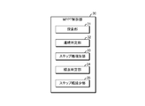
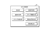
- the MPPT control unit 30 is a processing unit that performs generated power maximization control. That is, the MPPT control unit 30 searches for an operating point at which the output power of the power source 200 is maximum.
- the MPPT control unit 30 includes a search unit 31, a continuation determination unit 32, and a step width increase unit 33.
- the search unit 31 is a processing unit that searches for the maximum power point of the power source 200 by increasing or decreasing the operating voltage or operating current of the power source 200 connected to the power converter 400 by a predetermined step width. That is, the search unit 31 performs MPPT control by the hill climbing method.
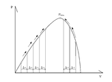
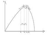
- the hill-climbing method for example, as shown in the power-voltage characteristic of FIG. 2, the output voltage is increased or decreased by changing the operating voltage of the power source 200 by a predetermined step width ⁇ v at a predetermined control timing.
- the predetermined control timing is a fixed time interval set in the storage unit 10 in advance.
- the predetermined step width is a fluctuation range of voltage or current set in the storage unit 10 in advance.
- the search unit 31 starts the search from the search start position set in the storage unit 10 in advance.
- the search start position is one of the position corresponding to the zero-voltage short-circuit current in FIG. 2 and the position corresponding to the zero-current open-circuit voltage. For this reason, you may start a search from the position of a short circuit current, and the position of an open circuit voltage. However, as will be described later, when the search range is set, it starts from either the upper limit or the lower limit.
- the continuation determination unit 32 is a processing unit that determines whether or not the search unit 31 has increased or decreased the operating voltage or operating current of the power source 200 continuously for a predetermined number of times. Continuous increase or decrease is a process in which the operating voltage or operating current is increased or decreased for each search executed in a certain control cycle, as shown in FIG. The case where it decreases after the decrease.
- the step width increasing unit 33 is a processing unit that increases the step width when the continuation determining unit 32 determines that it has been continuously increased or decreased a predetermined number of times.
- the predetermined number of times is a continuous number set in the storage unit 10 in advance.
- the increment to be increased is a value that increases the step width set in advance in the storage unit 10. As the increment setting, an amount to be added can be set, or a numerical value to be multiplied to be increased can be set.
- the search unit 31 increases the operating voltage V1 to V2 and V3 twice in succession by ⁇ V1, Assume that the power is increased from P1 to P3. Then, the step width increasing unit 33 increases ⁇ V2 obtained by adding an increment to ⁇ V1.
- the PCS 300 is connected to an input unit and an output unit.
- the input unit is a component that inputs information necessary for processing of the PCS 300, selection of processing, and instructions. An operator can input information stored in the storage unit 10 via the input unit.
- the input unit includes any input device that can be used at present or in the future, such as a keyboard, a mouse, a touch panel (including a touch panel), a switch, and a voice input unit.
- the output unit is a component that outputs information stored in the storage unit 10 in the PCS 300, processing results of each unit, and the like so that the worker can recognize the information.
- the output unit includes any output device that can be used now or in the future, such as a display device, a printer, a meter, a lamp, a speaker, and a buzzer. For example, an operator can confirm the operation state by displaying information being processed on the display device as a numerical value, a graph, or the like.
- the input unit and the output unit include those configured as an operation panel of the PCS 300 and those configured as a computer terminal for operation connected to the PCS 300 via a cable or a network.
- the MPPT control unit 30 of the present embodiment changes the voltage from a low voltage to a high voltage with a constant voltage step width ⁇ v1 in a direction in which the power increases from P1 to P3.
- the MPPT control unit 30 performs control so as to quickly reach the maximum power point Pmax by increasing the step width to ⁇ v2 larger than ⁇ v1.
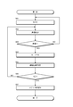
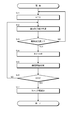
- the continuation determination unit 32 initializes a variable N indicating the number of continuations when the search unit 31 starts MPPT control (step S01). Then, the continuation determination unit 32 determines whether or not the voltage value is continuously increased or continuously decreased during the search by the search unit 31 (step S02). If the search unit 31 determines that the voltage value has been continuously increased or decreased (YES in step S03), the continuation determination unit 32 increments the variable N indicating the number of continuations (step S04).
- the continuation determination unit 32 determines whether or not the variable N has reached the predetermined number of times Y (step S05). When the continuation determination unit 32 determines that the predetermined number of times Y has not been reached (NO in step S06), the process returns to the continuation determination process (step S02). Further, if the search unit 31 determines that the voltage value has been continuously increased or decreased (YES in step S03), the continuation determination unit 32 increments the variable N (step S04).
- the step width increasing unit 33 determines whether or not the variable N has reached the predetermined number of times Y (step S05). If the step width increasing unit 33 determines that the predetermined number of times Y has been reached (YES in step S06), the step width of the search performed by the search unit 31 is increased (step S07).
- step S02 determines in step S02 that the voltage value is not continuously increasing or continuously decreasing (NO in step S03).
- the variable N is initialized ( Step S01). For this reason, only when the operating voltage continuously increases or decreases, the step width is increased.
- the search unit 31 continuously performs a search with the increased step width, but after that, when the voltage value is continuously increased or decreased, the above step width increase processing is performed.
- the control device 500 of the power converter 400 increases or decreases the operating voltage or operating current of the power source 200 connected to the power converter 400 by a predetermined step width, and thereby increases the maximum power point of the power source 200.
- the unit 32 includes a step width increasing unit 33 that increases the step width when it is determined that the unit 32 has continuously increased or decreased a predetermined number of times.
- the search unit 31 searching for the voltage value continuously increasing or decreasing a predetermined number of times means that the generated power is not the maximum point.
- the step width can be increased by detecting that the voltage value has increased a predetermined number of times.
- the search start point in the search unit 31 When the search start point in the search unit 31 is set at a position corresponding to a short circuit current or an open voltage, the search starts from a position far from the maximum power point. In this case, speeding up the search by increasing or decreasing the step width according to this embodiment is effective.
- the starting point of the search in the search unit 31 can be set on the high voltage side with respect to the maximum power point.
- the search may be started from the open circuit voltage.
- the MPPT control unit 30 of the present embodiment includes a repetition determination unit 34 and a step width reduction unit 35 as shown in FIG.
- the repeat determination unit 34 is a processing unit that determines whether or not the search unit 31 has repeatedly increased and decreased the operating voltage or operating current of the power source 200.
- the step width reduction unit 35 is a processing unit that reduces the step width when the repetition determination unit 34 determines that the repetition has been repeated a predetermined number of times.
- the predetermined number of times is set in advance in the storage unit 10 and is the number of repetitions of increase / decrease that is assumed to occur before and after the maximum power point.
- the decrement to be decreased is a value for decreasing the step width set in the storage unit 10 in advance. As the decrement setting, an amount to be subtracted can be set, or a numerical value to be multiplied or divided to be decreased can be set.
- the present embodiment basically performs the same operation as the first embodiment.
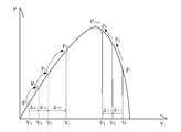
- the voltage value is repeatedly increased and decreased. Such an increase and decrease is expressed as going back and forth.
- the repetition determining unit 34 initializes a variable R indicating the number of repetitions when the search unit 31 starts MPPT control (step S11). Then, the repetition determination unit 34 determines whether or not the search unit 31 has been decreased following the increase in the voltage value during the search or has been increased subsequent to the decrease (step S12). When it is determined that the repetition determination unit 34 has decreased following the increase of the voltage value or increased following the decrease (YES in step S13), the repetition determination unit 34 increments the variable R indicating the number of repetitions (step S14). .
- step S15 determines whether or not the variable R has reached the predetermined number of times Z.
- step S16 determines that the predetermined number of times Z has not been reached.
- the repetition determining unit 34 increments the variable R (step S14).
- the step width reducing unit 35 determines whether or not the variable R has reached the predetermined number of times Z (step S15). When the step width reducing unit 35 determines that the predetermined number of times Z has been reached (YES in step S16), the step width of the search performed by the search unit 31 is decreased (step S17).
- step S12 determines in step S12 that the voltage value is not increased or decreased (NO in step S13)
- the variable R is initialized (step S11). For this reason, only when the operating voltage continuously increases and decreases, it becomes the target of the step width reduction process.
- the search unit 31 continuously performs a search with a reduced step width. After that, each time the increase / decrease is repeated, the search unit 31 performs the step width reduction process to search for the maximum power point.
- the search unit 31 determines whether or not the increase or decrease in the operating voltage or operating current of the power supply 200 has been repeated a predetermined number of times.
- the repetition determination unit 34 and the repetition determination unit 34 include a step width reduction unit 35 that decreases the step width when it is determined that the repetition determination unit 34 has been repeated a predetermined number of times.
- the search time can be shortened by increasing the step width.
- the increase and decrease in operating voltage are repeated, it can be estimated that the operating voltage is close to the maximum power point, so the step width is reduced to prevent a decrease in generated power.
- the minimum step width set in advance in the storage unit 10 is set based on the resolution of the carrier wave that the converter control unit 20 compares with the modulated wave. That is, when digital control is performed, as shown in FIG. 8A, the carrier wave has a minimum resolution n as a control period for comparison with the modulated wave.
- the resolution n is set to the minimum step width when the step width is reduced as in the second embodiment.
- the voltage is set as the resolution
- the power converter 400 is a current type
- the current is set as the resolution of the carrier wave to be compared with the modulation wave.
- FIG. 8B shows an example in the case of the voltage type power converter 400.
- the voltage type power converter 400 stores energy with voltage using the capacitor C as an energy buffer.
- the voltage varies to some extent depending on the amount of energy stored.
- the fluctuation range is Vmax to Vmin
- a value obtained by dividing the minimum value Vmin by the resolution n of the carrier wave is set as a minimum step width ⁇ V that decreases from the voltage value Vc.
- the minimum step width for decreasing the current value may be set based on the resolution. It should be noted that the step width does not necessarily match the minimum resolution. For example, if the resolution is sufficiently high, it may be twice the minimum resolution.
- the MPPT control unit 30 of the present embodiment includes a start position instruction unit 36 and a search stop unit 37, as shown in FIG.
- a search range by the search unit 31 is set in the storage unit 10 in advance.
- the search range is the upper limit and lower limit of the voltage or current to be searched.
- the reason for setting such a search range is mainly as follows. (1) Strategic reasons for prioritizing search time or accurate search (2) Constraints on specifications of power converter 400
- the maximum search range is a range corresponding to the short-circuit current and the open-circuit voltage.
- the search time can be adjusted. For example, it is possible to search in a short time by setting the search range in a range where the maximum power point is likely to be empirically.
- a curve indicating the current-voltage characteristics of the solar panel may indicate a plurality of peak points.
- the search range is narrowed down, only the peak points within the range are searched, so that the search can be performed in a short time.
- the search range is widened, it takes a long time to search, but the possibility of searching for the true maximum power point can be increased. That is, there is a strategic reason for setting the search range to how far the peak point is searched in relation to the search time.
- the power converter 400 when trying to search to a low voltage in the MPPT control, the power converter 400 approaches a short-circuit current, and thus a large current flows.
- the current that can flow is limited due to the specifications of the power converter 400, and thus searching that exceeds this limit may not be possible. That is, there are necessarily upper and lower limits of voltage or current that can be operated as the power converter 400.
- the upper limit and the lower limit of the search range are set according to the design of the power converter 400. That is, the reason for setting the search range is that there is an inherent restriction as the power converter 400.
- the search range in the present embodiment is not limited to a specific range, but can be an appropriate range considering the above (1) and (2).
- the fluctuation range due to the temperature coefficient is, for example, variation due to the temperature coefficient of the maximum power point in the reference state (STC) defined for measurement conditions such as light intensity, spectrum, and temperature.
- the fluctuation range depending on the product is a variation occurring in each product of the power supply 200 that is mass-produced.
- the detection error is an error of a detection value that can occur in the sensor, the control device 500, or the like.
- the margin is a range for giving a margin to the range.
- the search stop unit 37 is a processing unit that stops the search when the search by the search unit 31 reaches the upper limit or the lower limit of the search range a predetermined number of times. The predetermined number of times is set in the storage unit 10 in advance.
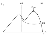
- FIG. 10 shows the upper and lower limits of the search range in the voltage-power characteristics.
- the voltage-power specification changes greatly due to changes in the external environment.
- the voltage-power curve changes in various forms depending on temperature and illuminance variation between cells. For this reason, an unintended operation can be considered.
- the start position instruction unit 36 resumes the operation from the upper limit when the search by the search unit 31 reaches the lower limit of the search range.
- the search unit 31 when the search by the search unit 31 reaches the upper limit of the search range, the start position instruction unit 36 resumes the operation from the lower limit.
- the search unit 31 always operates to search for the maximum point within the range.
- the search stop unit 37 stops the search when the search by the search unit 31 reaches the upper limit or the lower limit of the search range a predetermined number of times. That is, when the above operation is repeated a predetermined number of times, the search unit 31 stops the operation at the upper limit or the lower limit.
- the voltage-power characteristics are not the characteristics shown in FIG.
- the algorithm as described above is unnecessary, and when the lower limit is reached, the search returns to the upper limit, and when the upper limit is reached, the search is resumed by returning to the lower limit.
- the upper limit and the lower limit are prevented from stopping, and the maximum power point can be reliably reached.
- the MPPT control unit 30 of the present embodiment includes a suppressing unit 38 that suppresses a sudden change in the operating voltage or the operating current.
- the suppression unit 38 is, for example, a processing unit that limits differentiation with respect to a command value of voltage or current for generated power maximization control. That is, the suppression unit 38 suppresses rapid increase and decrease by adding dv / dt or di / dt as a tilt limit to the command value.
- the suppression unit 38 suppresses a sudden increase or decrease in the voltage or current command value for the converter control unit 20 by limiting the differentiation. As a result, the rapid increase or decrease in the voltage of the capacitor serving as the energy buffer of the power converter 400 or the current in the reactor is reduced.
- control cycle is constant, for example, as the voltage step width is increased, there is a possibility that energy suddenly flows into the energy buffer and breaks down. For this reason, suppression by the suppression part 38 is performed and the steep inflow is prevented.
- the energy buffer can be reduced in size and cost.
- the power conversion apparatus 100 can be reduced in size and cost.
- the MPPT control unit 30 in the present embodiment includes an average value calculation unit 39 as shown in FIG.
- the average value calculation unit 39 is a processing unit that calculates an average value of a voltage value or a current value in a predetermined range in an AC power cycle as an operating voltage or an operating current for which the search unit 31 searches for a maximum power point.
- the search unit 51 confirms increase / decrease in generated power by the hill-climbing method.
- the search unit 51 confirms increase / decrease in generated power by the hill-climbing method.
- such a vibration component may be removed by adding a capacitor to the power supply 200 side that is the input side of the power converter 400.
- the vibration component due to the frequency of the output of the power converter 400 becomes a relatively low frequency and cannot be completely removed.
- a capacitor to be added becomes large.
- the average value calculation unit 39 calculates the average power so that the search unit 31 does not erroneously determine the increase or decrease in generated power due to fluctuations in voltage or current.
- the power pulsation due to alternating current is dominated by the double frequency in the case of a single phase and the sixfold frequency in the case of three phases. For this reason, for example, the average value calculation unit 39 calculates the average power in the AC half cycle s, so that the search unit 31 can ignore the fluctuation.
- the power controlled by the power converter 400 is affected by harmonics from a load such as a half-wave rectifier that only flows when the voltage is positive or negative.
- a 1-fold frequency, that is, an AC frequency may be mixed.
- the average value calculator 39 calculates the average power in one cycle S of alternating current. Thereby, the search part 31 can ignore a fluctuation part.
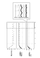
- the horizontal axis is time [s]
- the upper vertical axis is the voltage command [V]
- the middle vertical axis is the solar cell current [A] as the power source
- the lower vertical axis indicates the generated power [W] for each hour.
- the balloons in the horizontal direction of each figure are enlarged views of a part of the upper, middle and lower graphs.
- FIG. 15 is a comparative example in which the voltage step width is set to a relatively large constant value
- FIG. 16 is a comparative example in which the voltage step width is set to a relatively small constant value
- FIG. This is an example in which the voltage step width is variable as in the embodiment.
- FIG. 15 shows that in the generated power maximization control, since the voltage step width is increased, the time required from the start of control until the discovery of the maximum generated power point is short. However, since the voltage step width is large, there is a step in which the generated power temporarily decreases. Therefore, although the discovery of the maximum generated power point is fast, the amount of generated power is reduced.
- FIG. 16 shows that, in the generated power maximization control, the voltage step is reduced, so that there are few steps in which the generated power temporarily decreases, and conversely, the time required to find the maximum generated power point is long. For this reason, discovery of the maximum power point is slow, and it is impossible to follow the momentum of sunlight radiated on the solar cell, and the opportunity for power generation is lost, resulting in a decrease in the amount of generated power.
- FIG. 17 is an example of the present embodiment, and shows an operation waveform when the voltage step is varied.
- the time required to find the maximum generated power is short, and by decreasing the voltage step from there, the generated power will not temporarily drop, so the maximum generated power point can be found quickly and the amount of generated power Becomes larger.
- FIG. 17 is a circuit analysis to show the operation of decreasing the voltage step.
- the amount of change for decreasing or increasing the voltage step is not particularly limited. That is, 4V ⁇ 3V ⁇ 2V ⁇ 1V may be operated in the operation of decreasing the voltage step, and 1V ⁇ 3V ⁇ 4V may be operated in the operation of increasing the voltage step.
- This embodiment is not limited to the above aspects.
- various types of power converters constituting the power conversion apparatus and connected power sources are conceivable.
- the power conversion device is not limited to a so-called PCS device as long as it can perform MPPT control and converter control.
- a power converter device can also be comprised as a micro inverter connected to each of many solar cell modules.
- the specific contents and values of the information used in the embodiment are free and are not limited to specific contents and numerical values.
- a preferable value set as a setting value set in the storage unit depends on various factors such as the power generation status of the power source, the specifications of the power source and the power converter, and various values can be considered.
- the determination of the magnitude of the setting value, the determination of mismatch, etc. it is determined that the value is included as follows, or it is determined that the value is not included as larger, above, smaller, or below.
- the setting is also free.
Landscapes
- Engineering & Computer Science (AREA)
- Power Engineering (AREA)
- Electromagnetism (AREA)
- Sustainable Energy (AREA)
- Sustainable Development (AREA)
- Physics & Mathematics (AREA)
- Life Sciences & Earth Sciences (AREA)
- General Physics & Mathematics (AREA)
- Radar, Positioning & Navigation (AREA)
- Automation & Control Theory (AREA)
- Inverter Devices (AREA)
- Dc-Dc Converters (AREA)
- Control Of Electrical Variables (AREA)
Abstract
Description
(1)一次探索として、一定の電圧範囲内で設定された粗めの電圧ステップ幅で探索する。そして、複数の山の最も高い頂点付近を検出した後、二次探索として、一次探索よりも狭い電圧ステップ幅で探索する(例えば、特許文献1参照)。 The following techniques have been proposed as techniques for searching for such hill climbing methods.
(1) As a primary search, a search is performed with a coarse voltage step width set within a certain voltage range. Then, after detecting the vicinity of the highest vertex of a plurality of peaks, a search with a voltage step width narrower than the primary search is performed as a secondary search (see, for example, Patent Document 1).
本実施形態が適用される電源システム100を、図1を参照して説明する。この電源システム100は、電源200、PCS300を有する。
[構成]
[電源]
電源200は、電力の供給源である。この電源200としては、例えば、分散型電源とすることができる。分散型電源は、大規模発電所と比較して、電力の需要地に近い場所に分散して配置される発電設備である。本実施形態に適用される電源200としては、発電電力が比較的不安定な、太陽光発電装置、風力発電装置等が適しているが、これに限定するものではない。燃料電池、蓄電池等にも適用可能である。以下の説明では、太陽光発電装置を電源200とする場合を例に説明する。 [First Embodiment]
A
[Constitution]
[Power supply]
The
PCS300は、電源200の発電電力を負荷や系統に応じた電力に変換する電力変換装置である。PCS300は、電力変換器400、制御装置500を有する。 [PCS]
The
本実施形態の作用を、図3及び図4を参照して説明する。なお、以下の例は、電力変換器400の動作電圧を変化させて電力最大化制御を行う場合である。動作電流を変化させて電力最大化制御を行う場合も、基本的には同様の処理である。 [Action]
The effect | action of this embodiment is demonstrated with reference to FIG.3 and FIG.4. The following example is a case where the power maximization control is performed by changing the operating voltage of the
本実施形態のMPPT制御部30は、まず、図3に示すように、電力がP1~P3へと増える方向に、低電圧から高電圧へ一定の電圧のステップ幅Δv1で変化させる。このように、電圧を同じ方向に複数回変化させている場合には、最大電力点Pmaxに達していないことに相当する。この場合、MPPT制御部30は、ステップ幅を、Δv1よりも大きなΔv2に増加させることにより、速く最大電力点Pmaxにたどり着けるように制御する。 (Outline of processing)
First, as shown in FIG. 3, the
以上のような本実施形態におけるステップ幅の増加処理の手順を、図4のフローチャートを参照して説明する。なお、この増加処理は、探索部31による電力最大化処理の継続中に連続して行われている処理のうち、一部を抽出して示すものである。つまり、ステップ幅を増加させる一回当たりの処理を説明する。 (Processing procedure)
The procedure of the step width increasing process in the present embodiment as described above will be described with reference to the flowchart of FIG. This increase process is shown by extracting a part of the processes continuously performed while the power maximization process by the
本実施形態の電力変換器400の制御装置500は、電力変換器400に接続された電源200の動作電圧又は動作電流を、所定のステップ幅で増加又は減少させて、電源200の最大電力点を探索する探索部31と、探索部31が、電源200の動作電圧又は動作電流を、連続して増加させたか否か又は連続して減少させたか否かを判定する連続判定部32と、連続判定部32が、所定の回数連続して増加した又は減少したと判定した場合に、ステップ幅を増加させるステップ幅増加部33と、を有する。 [effect]
The
[構成]
本実施形態は、基本的には、上記の第1の実施形態と同様の構成である。但し、本実施形態のMPPT制御部30は、図5に示すように、繰返判定部34、ステップ幅減少部35を有する。繰返判定部34は、探索部31が、電源200の動作電圧又は動作電流の増加と減少を繰り返したか否かを判定する処理部である。 [Second Embodiment]
[Constitution]
This embodiment is basically the same configuration as the first embodiment. However, the
本実施形態の作用を、図6及び図7を参照して説明する。なお、以下の例は、電力変換器400の動作電圧を変化させて電力最大化制御を行う場合である。動作電流を変化させて電力最大化制御を行う場合も、基本的には同様の処理である。
(処理の概要)
電圧のステップ幅が大きい場合、探索する時間は短くなるものの、発電電力が一時的に下がる場合がある。逆に、電圧のステップ幅が小さい場合、探索時間は長くなるものの、発電電力が低下しない。このトレードオフから抜け出すために、発電電力が最大となるポイントに遠い場合、近い場合を、山登り法の動作から推定し、遠い場合には電圧ステップを増加させ、近い場合には電圧ステップを減少させる。 [Action]
The effect | action of this embodiment is demonstrated with reference to FIG.6 and FIG.7. The following example is a case where the power maximization control is performed by changing the operating voltage of the
(Outline of processing)
When the voltage step width is large, the search time is shortened, but the generated power may be temporarily reduced. Conversely, when the voltage step width is small, the search time is long, but the generated power does not decrease. In order to get out of this trade-off, it is estimated from the operation of the hill-climbing method when the generated power is far from or near the point where the generated power is maximum, and when it is far, the voltage step is increased, and when it is close, the voltage step is decreased. .
以上のような本実施形態におけるステップ幅の増加処理の手順を、図7のフローチャートを参照して説明する。なお、この処理は、探索部31による電力最大化処理の継続中に連続して行われている処理のうち、一部を抽出して示すものである。つまり、ステップ幅を減少させる一回当たりの処理を説明する。また、この処理は、上記の第1の実施形態の処理により、探索部31による探索が最大電力点近傍に来た場合に行われる処理である。 (Processing procedure)
The procedure of the step width increasing process in the present embodiment as described above will be described with reference to the flowchart of FIG. In addition, this process extracts and shows a part among the processes currently performed continuously while the electric power maximization process by the
本実施形態は、上記の第1の実施形態の構成に加えて、探索部31が、電源200の動作電圧又は動作電流の増加と減少を、所定の回数連続して繰り返したか否かを判定する繰返判定部34と、繰返判定部34が、所定の回数連続して繰り返したと判定した場合に、ステップ幅を減少させるステップ幅減少部35とを有する。 [effect]
In the present embodiment, in addition to the configuration of the first embodiment described above, the
本実施形態は、基本的には、上記の第2の実施形態と同様の構成である。但し、記憶部10にあらかじめ設定されるステップ幅の最小値が、変換器制御部20が、変調波と比較する搬送波の分解能に基づいて設定されている。つまり、ディジタル制御を行う場合、図8(a)に示すように、搬送波は、変調波との比較を行う制御周期として、最小の分解能nが存在する。 [Third Embodiment]
This embodiment is basically the same configuration as the second embodiment. However, the minimum step width set in advance in the
[構成]
本実施形態は、基本的には、上記の第2の実施形態と同様の構成である。但し、本実施形態のMPPT制御部30は、図9に示すように、開始位置指示部36、探索停止部37を有する。また、記憶部10には、探索部31による探索範囲が、あらかじめ設定されている。探索範囲は、探索する電圧又は電流の上限と下限である。 [Fourth Embodiment]
[Constitution]
This embodiment is basically the same configuration as the second embodiment. However, the
(1)探索時間を優先するか正確な探索を優先するかの戦略的理由
(2)電力変換器400の仕様上の制約 The reason for setting such a search range is mainly as follows.
(1) Strategic reasons for prioritizing search time or accurate search (2) Constraints on specifications of
以上のような本実施形態の作用を、図10を参照して説明する。図10は、電圧-電力特性における探索範囲の上限及び下限を示す。例えば、電源200は、外部の環境の変化によって、電圧-電力特定が大きく変化する。例えば、太陽電池は、温度やセル間の照度バラつきによって、さまざまな形に電圧一電力カーブが変化する。このため、意図しない動作をすることが考えられる。 [Action]
The operation of the present embodiment as described above will be described with reference to FIG. FIG. 10 shows the upper and lower limits of the search range in the voltage-power characteristics. For example, in the
上記のように、電圧-電力特性は、図10に示したような特性となるわけではない。しかし、山登り法による探索では、少なからず最大点とは違う山を探しに行くことがあり、それによって、発電電力最大化制御の探索範囲の上限、下限で止まってしまい、発電電力の最大点にたどり着かないことがある。 [effect]
As described above, the voltage-power characteristics are not the characteristics shown in FIG. However, in the search by the hill-climbing method, we often go to search for a mountain that is different from the maximum point, and as a result, it stops at the upper and lower limits of the search range of generated power maximization control, and it becomes the maximum point of generated power. Sometimes it doesn't arrive.
[構成]
本実施形態は、基本的には、上記の第2の実施形態と同様の構成である。但し、図11に示すように、本実施形態のMPPT制御部30は、動作電圧又は動作電流の急変を抑制する抑制部38を有する。この抑制部38は、例えば、発電電力最大化制御の電圧又は電流の指令値に対して、微分制限をする処理部である。つまり、抑制部38は、指令値に対して、傾き制限としてdv/dt又はdi/dtを入れることにより、急増、急減を抑制する。 [Fifth Embodiment]
[Constitution]
This embodiment is basically the same configuration as the second embodiment. However, as shown in FIG. 11, the
以上のような本実施形態の作用を、図12を参照して説明する。本実施形態においては、探索部31による探索において、抑制部38が、微分制限により、変換器制御部20に対する電圧又は電流の指令値の急増、急減を抑制する。これにより、電力変換器400のエネルギーバッファとなっているコンデンサの電圧又はリアクトルの電流の急増、急減が少なくなる。 [Action]
The operation of the present embodiment as described above will be described with reference to FIG. In the present embodiment, in the search by the
以上のよう本実施形態では、エネルギーバッファであるコンデンサの電圧又はリアクトルの電流を高速に制御できない場合においても、エネルギーバッファを小型化、低コスト化することができる。その結果、電力変換装置100の小型化、低コスト化が可能となる。 [effect]
As described above, in the present embodiment, even when the voltage of the capacitor serving as the energy buffer or the current of the reactor cannot be controlled at high speed, the energy buffer can be reduced in size and cost. As a result, the
[構成]
本実施形態は、基本的には上記の第2の実施形態と同様の構成である。但し、本実施形態におけるMPPT制御部30は、図13に示すように、平均値演算部39を有する。平均値演算部39は、探索部31が最大電力点を探索する動作電圧又は動作電流として、交流電力の周期における所定の範囲の電圧値又は電流値の平均値を求める処理部である。 [Sixth Embodiment]
[Constitution]
This embodiment is basically the same configuration as the second embodiment described above. However, the
以上のような本実施形態の作用を、図14を参照して説明する。まず、上記のように、探索部51は、山登り法で発電電力の増減を確認する。この場合、電力変換器40におけるスイッチング素子のスイッチの切り替えによる電圧又は電流の変動や、電力変換装置の出力が交流であった場合の変動がある。このため、常に一定の電力が維持されているわけではなく、微細な増減が生じている。 [Action]
The operation of the present embodiment as described above will be described with reference to FIG. First, as described above, the search unit 51 confirms increase / decrease in generated power by the hill-climbing method. In this case, there are fluctuations in voltage or current due to switching of the switching element of the switching element in the power converter 40, and fluctuations when the output of the power conversion device is alternating current. For this reason, constant power is not always maintained, and minute increases and decreases occur.
以上のように、本実施形態によれば、電力変換器400の入力側に大型のコンデンサを必要とせずに、発電電力の増減を誤って判断することを防止できる。このため、電力変換装置100の小型化、低コスト化、制御精度向上が可能となる。 [effect]
As described above, according to the present embodiment, it is possible to prevent an increase / decrease in generated power from being erroneously determined without requiring a large capacitor on the input side of the
さらに、上記の実施形態の効果を示す実施例を、図15、図16、図17を参照して説明する。図15、図16、図17は、全て横軸は時間[s]であり、上段の縦軸は電圧指令[V]、中段の縦軸が電源としての太陽電池電流[A]、下段の縦軸が時間毎の発電電力[W]を示す。各図の横の吹き出しは、上段、中段、下段のグラフの一部を拡大した図である。 [Example]
Furthermore, examples showing the effects of the above-described embodiment will be described with reference to FIGS. 15, 16, and 17. 15, 16, and 17, the horizontal axis is time [s], the upper vertical axis is the voltage command [V], the middle vertical axis is the solar cell current [A] as the power source, and the lower vertical axis. The axis indicates the generated power [W] for each hour. The balloons in the horizontal direction of each figure are enlarged views of a part of the upper, middle and lower graphs.
(1)本実施形態は、上記のような態様には限定されない。例えば、電力変換装置を構成する電力変換器、接続される電源は、上記のように種々のものが考えられる。このため、電力変換装置についても、いわゆるPCSと呼ばれる装置には限定されず、MPPT制御及び変換器制御が可能である装置であればよい。また、電力変換装置を、多数の太陽電池モジュールのそれぞれに接続されるマイクロインバータとして構成することもできる。 [Other Embodiments]
(1) This embodiment is not limited to the above aspects. For example, as described above, various types of power converters constituting the power conversion apparatus and connected power sources are conceivable. For this reason, the power conversion device is not limited to a so-called PCS device as long as it can perform MPPT control and converter control. Moreover, a power converter device can also be comprised as a micro inverter connected to each of many solar cell modules.
200 電源
300 PCS
400 電力変換器
500 制御装置
10 記憶部
20 変換器制御部
30 MPPT制御部
31 探索部
32 連続判定部
33 ステップ幅増加部
34 繰返判定部
35 ステップ幅減少部
36 開始位置指示部
37 探索停止部
38 抑制部
39 平均値演算部 100
400
Claims (13)
- 電力変換器に接続された電源の動作電圧又は動作電流を、所定のステップ幅で増加又は減少させて、前記電源の最大電力点を探索する探索部と、
前記探索部が、前記電源の動作電圧又は動作電流を、連続して増加させたか否か又は連続して減少させたか否かを判定する連続判定部と、
前記連続判定部が、所定の回数連続して増加又は減少したと判定した場合に、前記ステップ幅を増加させるステップ幅増加部と、
を有する電力変換器の制御装置。 A search unit for searching for the maximum power point of the power source by increasing or decreasing the operating voltage or operating current of the power source connected to the power converter by a predetermined step width;
A continuous determination unit that determines whether the search unit continuously increases or decreases the operating voltage or operating current of the power source; and
A step width increasing unit that increases the step width when the continuous determination unit determines that the predetermined number of times has increased or decreased continuously;
A control apparatus for a power converter. - 前記探索部が、前記電源の動作電圧又は動作電流の増加と減少を、所定の回数連続して繰り返したか否かを判定する繰返判定部と、
前記繰返判定部が、所定の回数連続して繰り返したと判定した場合に、前記ステップ幅を減少させるステップ幅減少部と、
を有する請求項1記載の電力変換器の制御装置。 A repeat determination unit that determines whether or not the search unit has repeatedly increased and decreased the operating voltage or operating current of the power source a predetermined number of times;
A step width reducing unit that reduces the step width when the repetition determining unit determines that the repetition has been repeated a predetermined number of times;
The control apparatus for a power converter according to claim 1, comprising: - 前記電力変換装置をPWM制御する搬送波の分解能に基いて、前記ステップ幅の最小幅を設定するステップ幅設定部を有する請求項1又は請求項2記載の電力変換器の制御装置。 The power converter control device according to claim 1 or 2, further comprising a step width setting unit that sets a minimum width of the step width based on a resolution of a carrier wave for PWM control of the power conversion device.
- 前記探索部による探索が、あらかじめ設定された探索範囲の上限に達した場合、次の探索を前記探索範囲の下限から開始させ、前記探索部による探索が前記探索範囲の下限に達した場合、次の探索を前記探索範囲の上限から開始させる開始位置指示部と、
を有する請求項1~3のいずれか1項に記載の電力変換器の制御装置。 When the search by the search unit reaches the upper limit of the preset search range, the next search starts from the lower limit of the search range, and when the search by the search unit reaches the lower limit of the search range, Starting position indicating unit for starting the search from the upper limit of the search range,
The power converter control device according to any one of claims 1 to 3, comprising: - 前記探索部による探索が前記探索範囲の上限又は下限に所定の回数達すると、探索を停止させる探索停止部を有する請求項4記載の電力変換器の制御装置。 The power converter control device according to claim 4, further comprising: a search stop unit that stops the search when the search by the search unit reaches a predetermined number of times at an upper limit or a lower limit of the search range.
- 前記動作電圧又は動作電流の急変を抑制する抑制部を有する請求項1~5のいずれか1項に記載の電力変換器の制御装置。 The power converter control device according to any one of claims 1 to 5, further comprising a suppressing unit that suppresses a sudden change in the operating voltage or the operating current.
- 前記抑制部は、前記動作電圧若しくは動作電流の指令値を通過させるローパスフィルタである請求項6記載の電力変換器の制御装置。 The control device for a power converter according to claim 6, wherein the suppression unit is a low-pass filter that passes a command value of the operating voltage or operating current.
- 前記抑制部は、前記動作電圧若しくは動作電流の指令値に対して微分制限を行う請求項6記載の電力変換器の制御装置。 The control device for a power converter according to claim 6, wherein the suppression unit performs differential restriction on a command value of the operating voltage or operating current.
- 前記電力変換器は、直流電力を所定の周期の交流電力に変換する変換器であって、
前記探索部が最大電力点を探索する動作電圧又は動作電流として、前記交流電力の周期における所定の範囲の電圧値又は電流値の平均値を求める平均値演算部を有する請求項1~8のいずれか1項に記載の電力変換器の制御装置。 The power converter is a converter that converts direct current power into alternating current power of a predetermined cycle,
The average value calculation unit for obtaining an average value of a voltage value or a current value in a predetermined range in the cycle of the AC power as an operating voltage or an operating current for the search unit to search for a maximum power point. The control apparatus of the power converter of Claim 1. - 前記探索部における探索の開始点が、短絡電流又は開放電圧に相当する位置に設定されている請求項1~9のいずれか1項に記載の電力変換器の制御装置。 The power converter control device according to any one of claims 1 to 9, wherein a search start point in the search unit is set at a position corresponding to a short-circuit current or an open-circuit voltage.
- 前記探索部における探索の開始点が、最大電力点に対して高電圧側に設定されている請求項1~9のいずれか1項に記載の電力変換器の制御装置。 The power converter control device according to any one of claims 1 to 9, wherein a search start point in the search unit is set on a high voltage side with respect to a maximum power point.
- 電力変換装置に接続された太陽電池の動作電圧又は動作電流を、所定のステップ幅で増加又は減少させて、前記太陽電池の最大電力点を探索する探索処理と、
前記探索処理により、太陽電池の動作電圧又は動作電流が、所定の回数連続して増加したか否か又は連続して減少したか否かを判定する連続判定処理と、
前記連続判定処理により、所定の回数連続して増加又は減少したと判定された場合に、前記ステップ幅を増加させるステップ幅増加処理と、
を、コンピュータに実行させる電力変換装置の制御プログラム。 A search process for searching for the maximum power point of the solar cell by increasing or decreasing the operating voltage or operating current of the solar cell connected to the power converter with a predetermined step width;
By the search process, a continuous determination process for determining whether the operating voltage or the operating current of the solar cell has been continuously increased or decreased continuously for a predetermined number of times, and
A step width increasing process for increasing the step width when it is determined by the continuous determination process that the predetermined number of times has been increased or decreased continuously;
Is a control program for a power converter that causes a computer to execute - 電力変換器と、
前記電力変換器を制御する変換器制御部と、
請求項1~11のいずれか1項に記載の制御装置と、
を有する電力変換装置。 A power converter;
A converter control unit for controlling the power converter;
A control device according to any one of claims 1 to 11,
A power conversion device.
Priority Applications (3)
| Application Number | Priority Date | Filing Date | Title |
|---|---|---|---|
| EP16749108.3A EP3258338B1 (en) | 2015-02-10 | 2016-02-03 | Control device for power conversion apparatus, control program, and power conversion apparatus |
| JP2016574750A JP6546203B2 (en) | 2015-02-10 | 2016-02-03 | CONTROL DEVICE FOR POWER CONVERTER, CONTROL PROGRAM, AND POWER CONVERTER |
| US15/504,564 US10097006B2 (en) | 2015-02-10 | 2016-02-03 | Control device for power converter, control program and power conversion device |
Applications Claiming Priority (2)
| Application Number | Priority Date | Filing Date | Title |
|---|---|---|---|
| JP2015024295 | 2015-02-10 | ||
| JP2015-024295 | 2015-02-10 |
Publications (1)
| Publication Number | Publication Date |
|---|---|
| WO2016129464A1 true WO2016129464A1 (en) | 2016-08-18 |
Family
ID=56614663
Family Applications (1)
| Application Number | Title | Priority Date | Filing Date |
|---|---|---|---|
| PCT/JP2016/053159 WO2016129464A1 (en) | 2015-02-10 | 2016-02-03 | Control device for power conversion apparatus, control program, and power conversion apparatus |
Country Status (4)
| Country | Link |
|---|---|
| US (1) | US10097006B2 (en) |
| EP (1) | EP3258338B1 (en) |
| JP (1) | JP6546203B2 (en) |
| WO (1) | WO2016129464A1 (en) |
Cited By (6)
| Publication number | Priority date | Publication date | Assignee | Title |
|---|---|---|---|---|
| JP2018165921A (en) * | 2017-03-28 | 2018-10-25 | 国立研究開発法人宇宙航空研究開発機構 | Power control system |
| JP2019175278A (en) * | 2018-03-29 | 2019-10-10 | 住友電気工業株式会社 | Power conversion apparatus and maximum power point follow-up control method |
| JP2019198211A (en) * | 2018-05-10 | 2019-11-14 | エルエス産電株式会社Lsis Co., Ltd. | Inverter control method |
| JP2020067812A (en) * | 2018-10-24 | 2020-04-30 | 矢崎総業株式会社 | Power control device |
| CN111641384A (en) * | 2020-04-28 | 2020-09-08 | 特变电工新疆新能源股份有限公司 | Photovoltaic power station string fault diagnosis method, device, equipment and readable storage medium |
| JP2022009818A (en) * | 2018-03-29 | 2022-01-14 | 住友電気工業株式会社 | Power conversion apparatus and maximum power point follow-up control method |
Families Citing this family (3)
| Publication number | Priority date | Publication date | Assignee | Title |
|---|---|---|---|---|
| JP6608761B2 (en) * | 2016-04-14 | 2019-11-20 | ファナック株式会社 | Motor drive device for suppressing voltage fluctuation of DC link capacitor |
| US10488879B2 (en) * | 2017-03-09 | 2019-11-26 | Ecole Polytechnique Federale De Lausanne (Epfl) | Device and method for performing maximum power point tracking for photovoltaic devices in presence of hysteresis |
| CN110677118B (en) * | 2019-09-23 | 2022-01-11 | 华为数字能源技术有限公司 | Optimizer, photovoltaic power generation system and IV curve scanning method of photovoltaic module |
Citations (2)
| Publication number | Priority date | Publication date | Assignee | Title |
|---|---|---|---|---|
| JP2012221151A (en) * | 2011-04-07 | 2012-11-12 | Mitsubishi Electric Corp | Control device for photovoltaic power generation device |
| JP2014146279A (en) * | 2013-01-30 | 2014-08-14 | Sumitomo Electric Ind Ltd | Maximum power point tracking control device and maximum power point tracking control method and photovoltaic power generation system |
Family Cites Families (9)
| Publication number | Priority date | Publication date | Assignee | Title |
|---|---|---|---|---|
| DE19524408C2 (en) * | 1995-07-04 | 1997-09-04 | Siemens Ag | Voltage converter for generating a regulated output voltage from an input voltage |
| JP3359206B2 (en) | 1995-10-31 | 2002-12-24 | キヤノン株式会社 | Battery power control device |
| US20070137688A1 (en) * | 2003-11-10 | 2007-06-21 | Tokyo Denki University | Photovoltaic power generator |
| US7737642B2 (en) * | 2004-10-18 | 2010-06-15 | Beyond Innovation Technology Co., Ltd. | DC/AC inverter |
| EP2357721B1 (en) * | 2008-11-18 | 2016-03-30 | Mitsubishi Electric Corporation | Power conversion device |
| US8674544B2 (en) * | 2009-01-26 | 2014-03-18 | Geneva Cleantech, Inc. | Methods and apparatus for power factor correction and reduction of distortion in and noise in a power supply delivery network |
| US8754627B1 (en) * | 2010-04-20 | 2014-06-17 | Solarbridge Technologies, Inc. | Multi-mode power point tracking |
| GB2482653B (en) * | 2010-06-07 | 2012-08-29 | Enecsys Ltd | Solar photovoltaic systems |
| JP6334312B2 (en) | 2014-08-08 | 2018-05-30 | 株式会社東芝 | Photovoltaic power generation system monitoring control device, monitoring control program, and solar power generation system |
-
2016
- 2016-02-03 EP EP16749108.3A patent/EP3258338B1/en active Active
- 2016-02-03 US US15/504,564 patent/US10097006B2/en active Active
- 2016-02-03 JP JP2016574750A patent/JP6546203B2/en active Active
- 2016-02-03 WO PCT/JP2016/053159 patent/WO2016129464A1/en active Application Filing
Patent Citations (2)
| Publication number | Priority date | Publication date | Assignee | Title |
|---|---|---|---|---|
| JP2012221151A (en) * | 2011-04-07 | 2012-11-12 | Mitsubishi Electric Corp | Control device for photovoltaic power generation device |
| JP2014146279A (en) * | 2013-01-30 | 2014-08-14 | Sumitomo Electric Ind Ltd | Maximum power point tracking control device and maximum power point tracking control method and photovoltaic power generation system |
Cited By (8)
| Publication number | Priority date | Publication date | Assignee | Title |
|---|---|---|---|---|
| JP2018165921A (en) * | 2017-03-28 | 2018-10-25 | 国立研究開発法人宇宙航空研究開発機構 | Power control system |
| JP2019175278A (en) * | 2018-03-29 | 2019-10-10 | 住友電気工業株式会社 | Power conversion apparatus and maximum power point follow-up control method |
| JP2022009818A (en) * | 2018-03-29 | 2022-01-14 | 住友電気工業株式会社 | Power conversion apparatus and maximum power point follow-up control method |
| JP7226505B2 (en) | 2018-03-29 | 2023-02-21 | 住友電気工業株式会社 | Power conversion device and maximum power point tracking control method |
| JP2019198211A (en) * | 2018-05-10 | 2019-11-14 | エルエス産電株式会社Lsis Co., Ltd. | Inverter control method |
| JP2020067812A (en) * | 2018-10-24 | 2020-04-30 | 矢崎総業株式会社 | Power control device |
| JP7140633B2 (en) | 2018-10-24 | 2022-09-21 | 矢崎総業株式会社 | power controller |
| CN111641384A (en) * | 2020-04-28 | 2020-09-08 | 特变电工新疆新能源股份有限公司 | Photovoltaic power station string fault diagnosis method, device, equipment and readable storage medium |
Also Published As
| Publication number | Publication date |
|---|---|
| EP3258338B1 (en) | 2021-06-16 |
| EP3258338A4 (en) | 2018-10-31 |
| JP6546203B2 (en) | 2019-07-17 |
| EP3258338A1 (en) | 2017-12-20 |
| US20180226803A1 (en) | 2018-08-09 |
| JPWO2016129464A1 (en) | 2017-11-16 |
| US10097006B2 (en) | 2018-10-09 |
Similar Documents
| Publication | Publication Date | Title |
|---|---|---|
| WO2016129464A1 (en) | Control device for power conversion apparatus, control program, and power conversion apparatus | |
| JP4457692B2 (en) | Maximum power tracking control method and power conversion device | |
| US9246407B2 (en) | Voltage balancing system and method for multilevel converters | |
| US7031176B2 (en) | Inverter | |
| CN108923462B (en) | Virtual synchronous machine control method and device for photovoltaic power generation system, converter and system | |
| US20130009700A1 (en) | Power Converter Circuit with AC Output | |
| US20150349681A1 (en) | Variable frequency speed control system and method of the same | |
| US10447070B2 (en) | Solar energy system with built-in battery charger and its method | |
| KR102087063B1 (en) | Method and apparatus for improved burst mode during power conversion | |
| EP2824533A2 (en) | Photovoltaic system | |
| EP2658109A1 (en) | Power converting apparatus, operating method thereof, and solar power generation system | |
| EP2555405B1 (en) | Converter, motor driving module, and refrigerating apparatus | |
| JP6334336B2 (en) | Power converter | |
| Tampubolon et al. | A study and implementation of three-level boost converter with MPPT for PV application | |
| JP5903341B2 (en) | Power generation control device, solar power generation system, and power generation control method | |
| CN115549191A (en) | Energy storage system and island detection method | |
| US10819209B2 (en) | Multi-source energy harvester system and power conversion apparatus and method thereof | |
| WO2018061424A1 (en) | Power conversion system and power conversion device | |
| CN103677067A (en) | Maximum power point tracing realizing method and device and photovoltaic power generation system | |
| CN105446413A (en) | Photovoltaic inverter and maximum power point tracking method and device thereof | |
| US20120013312A1 (en) | Power Control Device and Method thereof | |
| US20140306541A1 (en) | Method and apparatus for improving pv module fill factor using a voltage clamping circuit | |
| US20150142189A1 (en) | Power generation control system, method and non-transitory computer readable storage medium of the same | |
| JP6140037B2 (en) | Power converter | |
| JP2020191698A (en) | Power system |
Legal Events
| Date | Code | Title | Description |
|---|---|---|---|
| 121 | Ep: the epo has been informed by wipo that ep was designated in this application |
Ref document number: 16749108 Country of ref document: EP Kind code of ref document: A1 |
|
| REEP | Request for entry into the european phase |
Ref document number: 2016749108 Country of ref document: EP |
|
| WWE | Wipo information: entry into national phase |
Ref document number: 2016749108 Country of ref document: EP |
|
| WWE | Wipo information: entry into national phase |
Ref document number: 15504564 Country of ref document: US |
|
| ENP | Entry into the national phase |
Ref document number: 2016574750 Country of ref document: JP Kind code of ref document: A |
|
| NENP | Non-entry into the national phase |
Ref country code: DE |