WO2016120209A1 - A method and apparatus of encoding and decoding a color picture - Google Patents
A method and apparatus of encoding and decoding a color picture Download PDFInfo
- Publication number
- WO2016120209A1 WO2016120209A1 PCT/EP2016/051449 EP2016051449W WO2016120209A1 WO 2016120209 A1 WO2016120209 A1 WO 2016120209A1 EP 2016051449 W EP2016051449 W EP 2016051449W WO 2016120209 A1 WO2016120209 A1 WO 2016120209A1
- Authority
- WO
- WIPO (PCT)
- Prior art keywords
- component
- final
- luminance
- obtaining
- chrominance
- Prior art date
Links
Classifications
-
- G—PHYSICS
- G06—COMPUTING; CALCULATING OR COUNTING
- G06T—IMAGE DATA PROCESSING OR GENERATION, IN GENERAL
- G06T5/00—Image enhancement or restoration
-
- G—PHYSICS
- G09—EDUCATION; CRYPTOGRAPHY; DISPLAY; ADVERTISING; SEALS
- G09G—ARRANGEMENTS OR CIRCUITS FOR CONTROL OF INDICATING DEVICES USING STATIC MEANS TO PRESENT VARIABLE INFORMATION
- G09G5/00—Control arrangements or circuits for visual indicators common to cathode-ray tube indicators and other visual indicators
- G09G5/02—Control arrangements or circuits for visual indicators common to cathode-ray tube indicators and other visual indicators characterised by the way in which colour is displayed
-
- H—ELECTRICITY
- H04—ELECTRIC COMMUNICATION TECHNIQUE
- H04N—PICTORIAL COMMUNICATION, e.g. TELEVISION
- H04N19/00—Methods or arrangements for coding, decoding, compressing or decompressing digital video signals
-
- H—ELECTRICITY
- H04—ELECTRIC COMMUNICATION TECHNIQUE
- H04N—PICTORIAL COMMUNICATION, e.g. TELEVISION
- H04N19/00—Methods or arrangements for coding, decoding, compressing or decompressing digital video signals
- H04N19/10—Methods or arrangements for coding, decoding, compressing or decompressing digital video signals using adaptive coding
- H04N19/102—Methods or arrangements for coding, decoding, compressing or decompressing digital video signals using adaptive coding characterised by the element, parameter or selection affected or controlled by the adaptive coding
- H04N19/117—Filters, e.g. for pre-processing or post-processing
-
- H—ELECTRICITY
- H04—ELECTRIC COMMUNICATION TECHNIQUE
- H04N—PICTORIAL COMMUNICATION, e.g. TELEVISION
- H04N19/00—Methods or arrangements for coding, decoding, compressing or decompressing digital video signals
- H04N19/10—Methods or arrangements for coding, decoding, compressing or decompressing digital video signals using adaptive coding
- H04N19/169—Methods or arrangements for coding, decoding, compressing or decompressing digital video signals using adaptive coding characterised by the coding unit, i.e. the structural portion or semantic portion of the video signal being the object or the subject of the adaptive coding
- H04N19/186—Methods or arrangements for coding, decoding, compressing or decompressing digital video signals using adaptive coding characterised by the coding unit, i.e. the structural portion or semantic portion of the video signal being the object or the subject of the adaptive coding the unit being a colour or a chrominance component
-
- H—ELECTRICITY
- H04—ELECTRIC COMMUNICATION TECHNIQUE
- H04N—PICTORIAL COMMUNICATION, e.g. TELEVISION
- H04N19/00—Methods or arrangements for coding, decoding, compressing or decompressing digital video signals
- H04N19/30—Methods or arrangements for coding, decoding, compressing or decompressing digital video signals using hierarchical techniques, e.g. scalability
- H04N19/36—Scalability techniques involving formatting the layers as a function of picture distortion after decoding, e.g. signal-to-noise [SNR] scalability
-
- H—ELECTRICITY
- H04—ELECTRIC COMMUNICATION TECHNIQUE
- H04N—PICTORIAL COMMUNICATION, e.g. TELEVISION
- H04N19/00—Methods or arrangements for coding, decoding, compressing or decompressing digital video signals
- H04N19/44—Decoders specially adapted therefor, e.g. video decoders which are asymmetric with respect to the encoder
-
- H—ELECTRICITY
- H04—ELECTRIC COMMUNICATION TECHNIQUE
- H04N—PICTORIAL COMMUNICATION, e.g. TELEVISION
- H04N19/00—Methods or arrangements for coding, decoding, compressing or decompressing digital video signals
- H04N19/80—Details of filtering operations specially adapted for video compression, e.g. for pixel interpolation
-
- H—ELECTRICITY
- H04—ELECTRIC COMMUNICATION TECHNIQUE
- H04N—PICTORIAL COMMUNICATION, e.g. TELEVISION
- H04N19/00—Methods or arrangements for coding, decoding, compressing or decompressing digital video signals
- H04N19/85—Methods or arrangements for coding, decoding, compressing or decompressing digital video signals using pre-processing or post-processing specially adapted for video compression
-
- H—ELECTRICITY
- H04—ELECTRIC COMMUNICATION TECHNIQUE
- H04N—PICTORIAL COMMUNICATION, e.g. TELEVISION
- H04N19/00—Methods or arrangements for coding, decoding, compressing or decompressing digital video signals
- H04N19/90—Methods or arrangements for coding, decoding, compressing or decompressing digital video signals using coding techniques not provided for in groups H04N19/10-H04N19/85, e.g. fractals
- H04N19/98—Adaptive-dynamic-range coding [ADRC]
-
- H—ELECTRICITY
- H04—ELECTRIC COMMUNICATION TECHNIQUE
- H04N—PICTORIAL COMMUNICATION, e.g. TELEVISION
- H04N25/00—Circuitry of solid-state image sensors [SSIS]; Control thereof
- H04N25/50—Control of the SSIS exposure
- H04N25/57—Control of the dynamic range
-
- G—PHYSICS
- G09—EDUCATION; CRYPTOGRAPHY; DISPLAY; ADVERTISING; SEALS
- G09G—ARRANGEMENTS OR CIRCUITS FOR CONTROL OF INDICATING DEVICES USING STATIC MEANS TO PRESENT VARIABLE INFORMATION
- G09G2320/00—Control of display operating conditions
- G09G2320/02—Improving the quality of display appearance
- G09G2320/0271—Adjustment of the gradation levels within the range of the gradation scale, e.g. by redistribution or clipping
-
- G—PHYSICS
- G09—EDUCATION; CRYPTOGRAPHY; DISPLAY; ADVERTISING; SEALS
- G09G—ARRANGEMENTS OR CIRCUITS FOR CONTROL OF INDICATING DEVICES USING STATIC MEANS TO PRESENT VARIABLE INFORMATION
- G09G2340/00—Aspects of display data processing
- G09G2340/04—Changes in size, position or resolution of an image
- G09G2340/0407—Resolution change, inclusive of the use of different resolutions for different screen areas
- G09G2340/0428—Gradation resolution change
-
- G—PHYSICS
- G09—EDUCATION; CRYPTOGRAPHY; DISPLAY; ADVERTISING; SEALS
- G09G—ARRANGEMENTS OR CIRCUITS FOR CONTROL OF INDICATING DEVICES USING STATIC MEANS TO PRESENT VARIABLE INFORMATION
- G09G2340/00—Aspects of display data processing
- G09G2340/06—Colour space transformation
-
- G—PHYSICS
- G09—EDUCATION; CRYPTOGRAPHY; DISPLAY; ADVERTISING; SEALS
- G09G—ARRANGEMENTS OR CIRCUITS FOR CONTROL OF INDICATING DEVICES USING STATIC MEANS TO PRESENT VARIABLE INFORMATION
- G09G2360/00—Aspects of the architecture of display systems
- G09G2360/16—Calculation or use of calculated indices related to luminance levels in display data
Definitions
- a method and apparatus of encoding and decoding a color picture A method and apparatus of encoding and decoding a color picture.
- the present disclosure generally relates to picture/video encoding and decoding. Particularly, but not exclusively, the technical field of the present disclosure is related to encoding/decoding of a picture whose pixels values belong to a high-dynamic range.
- a color picture contains several arrays of samples (pixel values) in a specific picture/video format which specifies all information relative to the pixel values of a picture (or a video) and all information which may be used by a display and/or any other device to visualize and/or decode a picture (or video) for example.
- a color picture comprises at least one component, in the shape of a first array of samples, usually a luma (or luminance) component, and at least one another component, in the shape of at least one other array of samples.
- the same information may also be represented by a set of arrays of color samples (color component), such as the traditional tri-chromatic RGB representation.
- a pixel value is represented by a vector of C values, where c is the number of components. Each value of a vector is represented with a number of bits which defines a maximal dynamic range of the pixel values.
- Standard-Dynamic-Range pictures are color pictures whose luminance values are represented with a limited dynamic usually measured in power of two or f-stops. SDR pictures have a dynamic around 10 fstops, i.e.
- a ratio 1000 between the brightest pixels and the darkest pixels in the linear domain are coded with a limited number of bits (most often 8 or 10 in HDTV (High Definition Television systems) and UHDTV (Ultra-High Definition Television systems) in a non-linear domain, for instance by using the ITU-R BT.709 OEFT (Optico-Electrical-Transfer-Function) (Rec. ITU-R BT.709-5, April 2002) or ITU-R BT.2020 OETF ⁇ Rec. ITU-R BT.2020-1, June 2014) to reduce the dynamic.
- This limited non-linear representation does not allow correct rendering of small signal variations, in particular in dark and bright luminance ranges.
- HDR pictures High-Dynamic-Range pictures
- the signal dynamic is much higher (up to 20 f-stops, a ratio one million between the brightest pixels and the darkest pixels) and a new non-linear representation is needed in order to maintain a high accuracy of the signal over its entire range.
- raw data are usually represented in floating-point format (either 32-bit or 1 6-bit for each component, namely float or half-float), the most popular format being openEXR half-float format (1 6-bit per RGB component, i.e. 48 bits per pixel) or in integers with a long representation, typically at least 1 6 bits.
- a color gamut is a certain complete set of colors. The most common usage refers to a set of colors which can be accurately represented in a given circumstance, such as within a given color space or by a certain output device.
- a color gamut is sometimes defined by RGB primaries provided in the CIE1931 color space chromaticity diagram and a white point as illustrated in Fig. 1 .
- a gamut is defined in this diagram by the triangle whose vertices are the set of (x,y) coordinates of the three primaries RGB.
- the white point W is another given (x,y) point belonging to the triangle, usually close to the triangle center.
- a color volume is defined by a color space and a dynamic range of the values represented in said color space.
- a color gamut is defined by a RGB ITU-R Recommendation BT.2020 color space for UHDTV.
- An older standard, ITU-R Recommendation BT.709 defines a smaller color gamut for HDTV.
- the dynamic range is defined officially up to 100 nits (candela per square meter) for the color volume in which data are coded, although some display technologies may show brighter pixels.
- a change of gamut i.e. a transform that maps the three primaries and the white point from a gamut to another
- a change of space from XYZ to RGB is performed by a 3x3 matrix.
- a change of gamut can be performed by a 3x3 matrix.
- a gamut change from BT.2020 linear RGB to BT.709 XYZ can be performed by a 3x3 matrix.
- High Dynamic Range pictures are color pictures whose luminance values are represented with a HDR dynamic that is higher than the dynamic of a SDR picture.
- the HDR dynamic is not yet defined by a standard but one may expect a dynamic range up to a few thousands nits.
- a HDR color volume is defined by a RGB BT.2020 color space and the values represented in said RGB color space belong to a dynamic range from 0 to 4000 nits.
- Another example of HDR color volume is defined by a RGB BT.2020 color space and the values represented in said RGB color space belong to a dynamic range from 0 to 1000 nits.
- Color-grading a picture is a process of altering/enhancing the colors of the picture (or the video).
- color-grading a picture involves a change of the color volume (color space and/or dynamic range) or a change of the color gamut relative to this picture.
- two different color-graded versions of a same picture are versions of this picture whose values are represented in different color volumes (or color gamut) or versions of the picture whose at least one of their colors has been altered/enhanced according to different color grades. This may involve user interactions.
- a picture and a video are captured using tri-chromatic cameras into RGB color values composed of 3 components (Red, Green and Blue).
- the RGB color values depend on the trichromatic characteristics (color primaries) of the sensor.
- a first color-graded version of the captured picture is then obtained in order to get theatrical renders (using a specific theatrical grade).
- the values of the first color-graded version of the captured picture are represented according to a standardized YUV format such as BT.2020 which defines parameter values for UHDTV.
- the YUV format is typically performed by applying a non-linear function, so called Optical Electronic Transfer Function (OETF) on the linear RGB components to obtain non-linear components R'G'B', and then applying a color transform (usually a 3x3 matrix) on the obtained non-linear R'G'B' components to obtain the three components YUV.
- OETF Optical Electronic Transfer Function
- the first component Y is a luminance component and the two components U,V are chrominance components.
- a Colorist usually in conjunction with a Director of Photography, performs a control on the color values of the first color-graded version of the captured picture by fine-tuning/tweaking some color values in order to instill an artistic intent.
- the problem to be solved is the distribution of a compressed HDR picture (or video) while, at the same time, distributing an associated SDR picture (or video) representative of a color-graded version of said HDR picture (or video).
- a trivial solution is simulcasting both SDR and HDR picture (or video) on a distribution infrastructure but the drawback is to virtually double the needed bandwidth compared to a legacy infrastructure distributing adapted to broadcast SDR picture (or video) such as HEVC main 10 profile ("High Efficiency Video Coding", SERIES H: AUDIOVISUAL AND MULTIMEDIA SYSTEMS, Recommendation ITU-T H.265, Telecommunication Standardization Sector of ITU, April 2013).
- Using a legacy distribution infrastructure is a requirement to accelerate the emergence of the distribution of HDR pictures (or video). Also, the bitrate shall be minimized while ensuring good quality of both SDR and HDR version of the picture (or video).
- the SDR picture (or video) shall be viewable for users equipped with legacy decoder and display, i.e. in particular, overall perceived brightness (i.e. dark vs. bright scenes) and perceived colors (for instance, preservation of hues, etc.) should be preserved.
- the drawback of this solution is the lack of backward compatibility, i.e. the obtained reduced version of the picture (video) has not a sufficient visual quality to be considered as being viewable as a SDR picture (or video), and compression performance are somewhat poor.
- the disclosure sets out to remedy at least one of the drawbacks of the prior art with a method and device as claimed.
- the colors obtained by combining together a luminance component and two chrominance components representing a SDR version of a HDR color picture do not preserve hue and perceived saturation of the colors of the HDR color picture.
- Mapping the gamut of colors of such SDR picture onto the gamut of the colors of the HDR color picture to be encoded correct the hue and perceived saturation relatively to said HDR picture.
- the hue and perceived saturation of the color of the HDR picture are thus preserved increasing the visual quality of the decoded SDR picture whose perceived colors match the original HDR better.
- mapping the luminance and chrominance components onto a final luminance component and two final chrominance components comprises:
- This embodiment allows getting a SDR color picture by combining together the decoded luminance and chrominance components.
- This SDR color picture may be displayed by a legacy SDR display.
- a SDR color picture is viewable by an end-user from his legacy SDR display.
- the method allows thus backward compatibility with any SDR legacy display.
- a HDR picture may be formed from final luminance and chrominance components obtained by mapping the luminance and chrominance components (SDR color picture) onto said final luminance and chrominance components avoiding thus simulcasting both the SDR and HDR pictures.
- obtaining said two chrominance components from said at least one intermediate color component comprises:
- the square root function is used to approximate an OEFT (Optico- Electrical-Transfer-Function) required at the encoding side.
- OEFT Optico- Electrical-Transfer-Function
- Such an approximation leads non-ambiguous invertible formulas and to a low complexity decoder partly because the EOTF (Electro-Optical-Transfer- Function), that shall be applied at the decoder side to decode the full dynamic input picture, is then a square function.
- the SDR picture shows somewhat consistent colors because the square root is a good approximation of the standard SDR OETF defined by the ITU-R Recommendation BT.709/BT.2020, used in HD/UHD TV, which is mainly a power 0.45.
- the present disclosure relates to a method of decoding a color picture from a bitstream.
- the disclosure relates to devices comprising a processor configured to implement the above methods, a computer program product comprising program code instructions to execute the steps of the above methods when this program is executed on a computer, a processor readable medium having stored therein instructions for causing a processor to perform at least the steps of the above methods, and a non- transitory storage medium carrying instructions of program code for executing steps of the above methods when said program is executed on a computing device.
- - Fig. 1 shows examples of chromaticity diagrams
- FIG. 2 shows schematically a diagram of the steps of a method of encoding a color picture in accordance with an embodiment of the disclosure
- - Fig. 3 illustrates the principle of a gamut mapping in accordance with the present disclosure
- FIG. 4 shows schematically a diagram of the sub-steps of the step 12 in accordance with an embodiment of the disclosure
- FIG. 5 shows schematically a diagram of the sub-steps of the step 1 1 in accordance with an embodiment of the disclosure
- FIG. 6 shows schematically a diagram of the sub-steps of the step 170 in accordance with an embodiment of the disclosure
- FIG. 7 shows schematically a diagram of the sub-steps of the step 170 in accordance with an embodiment of the disclosure
- FIG. 8 shows schematically a diagram of the steps of a method of decoding a color picture from at least one bitstream in accordance with an embodiment of the disclosure
- FIG. 9 shows schematically a diagram of the sub-steps of the step 22 in accordance with an embodiment of the disclosure.
- - Fig. 10 shows schematically a diagram of the sub-steps of the step 23 in accordance with an embodiment of the disclosure
- - Fig. 11a-b shows schematically a diagram of the sub-steps of the step
- Fig. 12 shows schematically a diagram of the sub-steps of the step
- FIG. 13 shows an example of an architecture of a device in accordance with an embodiment of the disclosure
- FIG. 14 shows two remote devices communicating over a communication network in accordance with an embodiment of the disclosure.
- Fig. 15 illustrates an example of set of elements in the CEI 1931 diagram of a gamut.
- each block represents a circuit element, module, or portion of code which comprises one or more executable instructions for implementing the specified logical function(s).
- the function(s) noted in the blocks may occur out of the order noted. For example, two blocks shown in succession may, in fact, be executed substantially concurrently or the blocks may sometimes be executed in the reverse order, depending on the functionality involved.
- a factor depends on a modulation value Ba.
- a modulation (or backlight) value is usually associated with an HDR picture and is representative of the brightness of the HDR picture.
- the term (modulation) backlight is used by analogy with TV sets made of a color panel, like a LCD panel for instance, and a rear illumination apparatus, like a LED array for instance.
- the rear apparatus usually generating white light, is used to illuminate the color panel to provide more brightness to the TV.
- the luminance of the TV is the product of the luminance of rear illuminator and of the luminance of the color panel.
- This rear illuminator is often called “modulation” or "backlight” and its intensity is somewhat representative of the brightness of the overall scene.
- the disclosure is described for encoding/decoding a color picture but extends to the encoding/decoding of a sequence of pictures (video) because each color picture of the sequence is sequentially encoded/decoded as described below.
- the present disclosure is not limited to any color space in which the three components Ec are represented but extends to any color space such as RGB, CIELUV, XYZ, CIELab, etc.
- Fig. 2 shows schematically a diagram of the steps of a method of encoding a color picture I in accordance with an embodiment of the disclosure.
- a module C obtains a luminance component L and two chrominance components C1 and C2 from a color picture I to be encoded.
- the components (L, C1 , C2) may belong to the YUV color space, obtained after applying an OETF on the color picture I, and the color components Ec may belong either to a linear RGB or XYZ color space.
- a module GM maps the luminance L and chrominance C1 , C2 components onto a final luminance component L" and two final chrominance components C"1 , C"2 in order that the gamut G2 of colors obtained from said final luminance (L") and chrominance (C"1 , C"2) components maps onto the gamut G1 of the colors of the color picture I to be encoded.
- Fig. 3 illustrates such a gamut mapping.
- dashed line is represented the gamut (R,G,B,W) of the colors obtained from the component L and the two chrominance components C1 and C2 and in solid line the gamut (R ⁇ G', B', W) of the colors of the picture I to be encoded.
- Mapping the gamut (R, G, B, W) onto the gamut (FT, G', B', W) means mapping the primaries R, G, B to the primaries R', G', B' respectively and mapping the white point W to the white point W.
- the purpose of the mapping is to transform (L, C1 , C2) into (L", C"1 , C"2) such that the perceived colors obtained from the L", C"1 , C"2 components match the colors of the color picture I better than (L, C1 , C2) do.
- an encoder ENC encodes the final luminance L" component and the two final chrominance components C"1 , C"2.
- the encoded component L" and chrominance components C"1 , C"2 are stored in a local or remote memory and/or added into a bitstream F.
- the two final chrominance components C"1 , C"2 are obtained by scaling (step 121 ) each of the two chrominance components C1 , C2 by a factor /? _1 (L(i)) that depends on the value of each pixel i of the luminance component L, and a module LCC (step 122) obtains the final luminance component L" by linearly combining together the luminance component L and the two final chrominance components C"1 , C"2:
- m and n are coefficients (real values) that avoid color saturation by correcting the highest luminance peaks.
- the factor /? _1 (L(i)) further depends on a modulation value Ba.
- the coefficients m and n are stored in either a local or remote memory and/or added to a bitstream BF as illustrated in Fig. 4.
- the values of the final luminance component L" are always lower than the values of the luminance component L:
- the factor /? _1 (L(i)) is obtained from a Look-Up-Table (LUT) for a specific luminance value L(i), and optionally further for a specific modulation value Ba and.
- LUT Look-Up-Table
- a specific factor /? _1 (L(i)) is stored in a LUT for each specific modulation value Ba.
- the factor /? _1 (L(i)) is obtained for a value of a pixel of the luminance component L by interpolating the luminance peaks between the multiple luminance peaks for which LUT are stored.
- the factor /? _1 (L(i)) for a specific modulation value Ba is obtained for a value of a pixel of the luminance component L by interpolating the luminance peaks between the multiple luminance peaks for which LUT are stored.
- the factor /? _1 (L(i)) and the coefficients m and n in equation (A) are obtained as follows.
- ⁇ ⁇ ( ⁇ ) is a mapping function depending on the linear luminance Y of the color picture I.
- the linear luminance Y is obtained as a linear combination of the components Ec of the color picture I.
- the luminance component L is related unambiguously to the linear luminance Y and the backlight value Ba, such that one may write
- mapping function is seen as a function of the luminance component L.
- A1 is the one-row matrix that defines the linear luminance Y from the linear RGB, i.e.
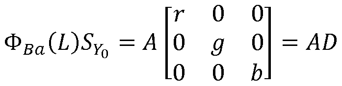
- mapping function 0 Sa (L) The purpose of the mapping function 0 Sa (L) is to map back 5y o onto the three primaries of the gamut G2.
- the matrix S YQ should be under the form : r 0 0
- mapping matrix is determined up to a scaling factor ⁇ .
- mapping function may be expressed by:
- ⁇ ⁇ ⁇ 1) ⁇ 0 ⁇ - 0 (G)
- Equations (B) and (G) show that the mapping function has two effects: first, the dynamic of the luminance component L is scaled by a scaling factor ⁇ and, second, the chrominance components C1 and C2 are also scaled by a scaling factor ⁇ '1 .
- Equation (G) Equation (G) becomes:
- the luminance component L is obtained back from L", C"1 , C"2 by applying the matrix O Q 1 and then, since L is known, one finds the factor ⁇ ( ⁇ , 1( ⁇ )) to apply to the final chrominance components C"1 , C"2 to get the chrominance components C1 , C2 back.
- mapping function 0 Sa (L) is then provided by equation (H) where the constant matrix ⁇ 0 is used for all luminance level up to the luminance peak P of the color image I, and ⁇ defined on the full range of luminance up to the luminance peak P.
- the factor ⁇ ⁇ 1 ⁇ , ⁇ ( ⁇ ), ⁇ , ⁇ ) is considered as depending also on the coefficients m and n which are given as explained in the previous embodiment.
- the factor is thus the single unknown value in step 12.
- the factor is obtained such that a gamut distortion calculated between the gamuts G1 and G2 is minimized.
- the factor ⁇ '1 is the optimal factor under the condition of gamut preservation.
- ⁇ , ⁇ , ⁇ , ⁇ ) argmirip ⁇ -i GD(/? test -1 ),
- the gamut distorsion is defined by the sum of the square error between an element (xj,yj) of the gamut G1 and an associated element (x'j.y'j) of the gamut G2.
- Fig. 15 illustrates an example of set of elements (xj,yj) in the CEI 1931 diagram of a gamut. Note the XYZ coordinates of each element (xj,yj) are given by
- Xj Yoxj/yj
- a module IC obtains a component Y that represents the luminance of the color picture I by linearly combining together the three components Ec:
- A1 is the first row of a 3x3 matrix A that defines a color space transforms from the (E1 , E2, E3) color space to a color space (Y, C1 , C2).
- a module FM obtains the luminance component L by applying a non-linear function f on the component Y:
- Ba is a modulation value obtained from the component Y by the module BaM (step 120).
- the dynamic range of the component Y is reduced in order that the luminance values of the component L are represented by using 10 bits.
- the component Y is divided by the modulation value Ba before applying the non-linear function f:
- the non-linear function f is a gamma function:
- Y i equals either Y or Y/Ba according to the embodiments of eq. (1 ) or (2), B is a constant value, y is a parameter (real value strictly below 1 ).
- the non-linear function f is a S-Log function:
- a, b and c are parameters (real values) of a SLog curve determined such that f(0) and f(1 ) are invariant, and the derivative of the SLog curve is continuous in 1 when prolonged by a gamma curve below 1 .
- a, b and c are functions of the parameter y.
- a value of ⁇ close to 1/2.5 is efficient in terms of HDR compression performance as well as good viewability of the obtained SDR luma.
- the non-linear function f is either a gamma correction or a SLog correction according to the pixel values of the component Y.
- the module FM applies either the gamma correction or the SLog correction according to the pixel values of the component Y.
- An information data Inf may indicate whether either the gamma correction or Slog correction applies. For example, when the pixel value of the component Y is below a threshold (equal to 1 ), then the gamma correction is applied and otherwise the SLog correction is applied.
- the modulation value Ba is an average, median, min or max value of the pixel values of the component Y.
- These operations may be performed in the linear HDR luminance domain Yin or in a non-linear domain like ln(Y) or YY with ⁇ 1 .
- a modulation value Ba is determined for each color picture, a Group of Pictures (GOP) or for a part of a color picture such as, but not limited to, a slice or a Transfer Unit as defined in HEVC.
- GOP Group of Pictures
- the value Ba and/or the parameters of the non-linear function f (such as a, b, c or y) and/or the information data Inf is (are) stored in a local or remote memory and/or added into a bitstream BF as illustrated in Figs. 2 and 5.
- a color component Ec may be obtained directly from a local or a remote memory or by applying a color transform on the color picture I.
- step 1 60 that depends on the value of a pixel i of the component L, E c ' ⁇ i) is the value of the pixel i of the intermediate color component E'c, and E c (i) is the value of the pixel i of the color component Ec.
- Scaling by a factor means multiplying by said factor or dividing by the inverse of said factor. Scaling each color component Ec by the factor r(L) that depends on the luminance component L preserves the hue of the colors of the color picture I.
- the factor r(L) is the ratio of the luminance component L over the component Y:
- the value Y(i) of a pixel of the component Y depends non-ambiguously on the value L(i) of a pixel of the luminance component L, such that the ratio can be written as a function of L(i) only.
- This embodiment is advantageous because scaling each color component Ec by the factor r(L) that further depends on the component Y preserves the hue of the colors of the color picture I and thus improves the visual quality of the decoded color picture.
- colorfulness, chroma, and saturation refer to the perceived intensity of a specific color.
- Colorfulness is the degree of difference between a color and gray.
- Chroma is the colorfulness relative to the brightness of another color that appears white under similar viewing conditions.
- Saturation is the colorfulness of a color relative to its own brightness.
- a highly colorful stimulus is vivid and intense, while a less colorful stimulus appears more muted, closer to gray.
- a color is a "neutral" gray (a picture with no colorfulness in any of its colors is called grayscale). Any color can be described from its colorfulness (or chroma or saturation), lightness (or brightness), and hue.
- the definition of the hue and saturation of the color depends on the color space used to represent said color.
- the saturation s uv is defined as the ratio between the chroma C * v over the luminance L * .
- the saturation is defined as the ratio of the chroma over the luminance:
- the colors of the picture I2 are thus differently perceived by a human being because the saturation and the hue of the colors changed.
- the method (step 150) determines the chrominance components C1 and C2 of the picture I2 in order that the hue of the colors of the picture I2 best match the hue of the colors of the color picture I.
- the factor r(L) is given by:
- This last embodiment is advantageous because it prevents the factor from going to zero for very dark pixels, i.e. allows the ratio to be invertible regardless of the pixel value.
- step 170 the two chrominance components C1 , C2 are obtained from said at least one intermediate color components E'c.
- step 171 an OETF on each intermediate color component (E'c) :
- the OETF is defined by the ITU-R recommendation BT.709 or BT.2020 and stated as follows
- This embodiment allows a reduction of the dynamic range according to a specific OETF but leads to a complex decoding process as detailed later.
- the OETF is approximated by a square root, i.e. at least one intermediate component Dc
- This embodiment is advantageous because it provides a good approximation of the OETF defined by the ITU-R recommendation BT.709 or
- a module LC1 obtains the two chrominance components C1 and C2 by linearly combining the three intermediate components Dc:
- FIG. 8 shows schematically a diagram of the steps of a method of decoding a color picture from at least a bitstream in accordance with an embodiment of the disclosure.
- a decoder DEC obtains a luminance component L" and two chrominance components C"1 , C"2 either from a local or remote memory or by decoding at least partially a bitstream F.
- a module IGM obtains a final luminance component L and two final chrominance components C1 , C2 from said luminance L" and chrominance C"1 , C"2 components by applying an inverse mapping on the colors obtained from said luminance L" and chrominance C"1 , C"2 components.
- a module INVC obtains at least one color component Ec of the color picture to be decoded from said final luminance L component and said two final chrominance C1 , C2 components.
- the decoded picture being obtained by combining together said at least one color component Ec.
- a module ILCC obtains (step 222) the final luminance component L by linearly combining together the luminance component L" and the two chrominance components C"1 , C"2, and the two final chrominance components C1 , C2 are obtained by scaling (step 221 ) each of the two chrominance components C"1 , C"2 by a factor ⁇ (L(i)) that depends on the value of each pixel i of the final luminance component L, and:
- m and n are coefficient (real values).
- the coefficients m and n may be those obtained by the factorization of the matrix 0 Sa (L) in equation (G), i.e. m and n are those obtained in ⁇ 0 . Consequently, they depend on the gamut of the color picture I (for instance BT.709 or BT.2020 gamut).
- the factor further depends on a modulation value Ba.
- Equation (J) is considered as being an inverse mapping applies on the colors obtained from the luminance L" and chrominance C"1 , C"2 components. Equation (J) is directly obtained from equation (A) that is considered as being a color mapping.
- the values of the final luminance component L are always higher than the values of the luminance component L":
- This embodiment is advantageous because it ensures that the final luminance component L does not exceed a potential clipping value that is usually used by the decoder to define a luminance peak.
- a luminance peak is required by a decoder and when the final luminance component L is given by equation (J), the final luminance component L is clipped introducing some artefacts.
- the modulation value Ba and/or the coefficients m and n are obtained from a remote or local memory such a Look- Up-Table, or from a bitstream BF as illustrated in Fig. 9.
- the factor /? _1 (L(i)) is obtained from a Look-Up-Table (LUT) for a specific value L(i) of the final luminance component L and, optionally further from a specific modulation value Ba and.
- LUT Look-Up-Table
- a specific factor /? _1 (L(i)) is stored in a LUT for each specific modulation value Ba.
- the factor /? _1 (L(i)) for a specific modulation value Ba is obtained for a value of a pixel of the final luminance component L by interpolating the luminance peaks between the multiple luminance peaks for which LUT are stored.
- a module IFM obtains a first component Y by applying a non-linear function f "1 on the final luminance component L in order that the dynamic of the first component Y is increased compared to the dynamic of the final luminance component L:
- the non-linear function f "1 is the inverse of the non-linear function f (step 130).
- the parameters of the non-linear function f "1 (such as a, b, c or y) and/or the information data Inf is (are) obtained from a local or remote memory (for example a Look-Up-Table) and/or from a bitstream BF as illustrated in Fig. 10.
- a local or remote memory for example a Look-Up-Table
- the luminance component L is multiplied by the modulation value Ba after having applied the non-linear function f :
- the non-linear function f "1 is the inverse of a gamma function.
- Y i equals Y or Y/Ba according to the embodiments of eq. (A3) or (A4)
- B is a constant value
- y is a parameter (real value strictly below 1 ).
- the non-linear function f "1 is the inverse of a S-Log function.
- the non-linear function f is the inverse of either a gamma correction or a SLog correction according to the pixel values of the component Y. This is indicated by the information data Inf.
- a module ILC obtains at least one color component Ec from the first component Y, the two final chrominance components C1 , C2, and from a factor r(L) that depends on the final luminance component L.
- the decoded color picture is then obtained by combining together said at least one color component Ec.
- each intermediate color component E'c (step 1 71 in Fig. 6)
- the intermediate components Dc are related to the component Y, the two final chrominance components C1 , C2 and the factor r(L) :
- EOTF Electro-Optical Trans Function
- Equation (A5b) provides
- a module ILEC obtains three intermediate color component E'c from the first component Y, the two final chrominance components C1 , C2 and the factor r(L) as above explained.
- the three color components Ec are obtained by scaling each intermediate color component E'c by the factor r(L):
- r(L(i)) is the factor given by step 1 60 that depends on the value of a pixel i of the final luminance component L
- E c ' (i) is the value of the pixel i of an intermediate color component E'c
- E c (i) is the value of the pixel i of the color component Ec.
- step 231 before step 232 is the inverse of the order step 150 followed by step 170 of the encoding method.
- the OEFT is a square root function and the EOTF is then a square function.
- the OEFT is a cubic root function and the EOTF is then a cubic function.
- Fc are components equal to OETF(Ec) and /0ETF(r(L))
- Equation (10) provides
- equation (A9) becomes:
- step 232 two intermediate components C'1 and C'2 are obtained by scaling the two final chrominance components C1 and C2 by the factor OEFT(r(L(i))) where OETF is the function used in step 1 71 in Fig. 6:
- a module ILEC obtains the three color components Ec from the first component Y and the two intermediate chrominance components C'1 , C'2 as above explained.
- the OEFT is a square root function and the EOTF is then a square function. Then, in step 232 in Fig. 11 b, the two intermediate components C'1 and C'2 are obtained by scaling the two final chrominance components C1 and C2 by the factor jr(L(i)
- Equation(9) becomes
- Equation (1 1 ) becomes:
- Equation (A14) is a second order equation that may be solved analytically.
- This analytic solution leads to a specific embodiment of the step 231 as illustrated in Fig. 12.
- This embodiment is advantageous because it allows an analytic expression of the EOTF (inverse of the OETF) and thus of the decoded components of the picture.
- the EOTF is then the square function that is a low complexity process at the decoding side.
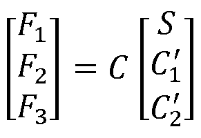
- a module SM obtains a second component S by combining together the two intermediate chrominance components C'1 , C'2 and the first component Y:
- a module LC2 obtains the three solver components Fc by linearly combining together the intermediate chrominance component C'1 , C'2 and a second component S:
- C is a 3x3 matrix defined as the inverse of the matrix A.
- step 231 2 the three color components Ec are obtained by taking the square of each intermediate color components (Dc) :
- the matrix A determines the transform of the picture I to be encoded from the color space (E1 , E2, E3), in which the pixel values of the picture to be encoded are represented, to the color space (Y, C1 , C2).
- Such a matrix depends on the gamut of the color picture to be encoded.
- the OEFT is a cube root function and the EOTF is then a cubic function. Then, in step 232 in Fig. 11 b, the two intermediate components C'1 and C'2 may then be obtained by scaling the two final chrominance components C1 and C2 by the factor 3 Vr(L(i) :
- the EOTF is then a cubic function thus leading to an equation (14) on F i being a more complex third order equation which can be solved analytically by the so-called Cardano's method.
- the decoder DEC is configured to decode data which have been encoded by the encoder ENC.
- the encoder ENC (and decoder DEC) is not limited to a specific encoder (decoder) but when an entropy encoder (decoder) is required, an entropy encoder such as a Huffmann coder, an arithmetic coder or a context adaptive coder like Cabac used in H264/AVC or HEVC is advantageous.
- the encoders ENC (and decoder DEC) is not limited to a specific encoder which may be, for example, an frame/video legacy coder with loss like JPEG, JPEG2000, MPEG2, H264/AVC or HEVC.
- the modules are functional units, which may or not be in relation with distinguishable physical units. For example, these modules or some of them may be brought together in a unique component or circuit, or contribute to functionalities of a software. A contrario, some modules may potentially be composed of separate physical entities.
- the apparatus which are compatible with the disclosure are implemented using either pure hardware, for example using dedicated hardware such ASIC or FPGA or VLSI, respectively « Application Specific Integrated Circuit » « Field-Programmable Gate Array » « Very Large Scale Integration » or from several integrated electronic components embedded in a device or from a blend of hardware and software components.
- Fig. 13 represents an exemplary architecture of a device 1300 which may be configured to implement a method described in relation with Fig. 1-12.
- Device 1300 comprises following elements that are linked together by a data and address bus 1301 :
- microprocessor 1302 which is, for example, a DSP (or Digital Signal Processor);
- RAM or Random Access Memory
- the battery 1306 is external to the device.
- the word « register » used in the specification can correspond to area of small capacity (some bits) or to very large area (e.g. a whole program or large amount of received or decoded data).
- ROM 1303 comprises at least a program and parameters. Algorithm of the methods according to the disclosure is stored in the ROM 1303. When switched on, the CPU 1302 uploads the program in the RAM and executes the corresponding instructions.
- RAM 1304 comprises, in a register, the program executed by the CPU 1302 and uploaded after switch on of the device 1300, input data in a register, intermediate data in different states of the method in a register, and other variables used for the execution of the method in a register.
- the implementations described herein may be implemented in, for example, a method or a process, an apparatus, a software program, a data stream, or a signal. Even if only discussed in the context of a single form of implementation (for example, discussed only as a method or a device), the implementation of features discussed may also be implemented in other forms (for example a program).
- An apparatus may be implemented in, for example, appropriate hardware, software, and firmware.
- the methods may be implemented in, for example, an apparatus such as, for example, a processor, which refers to processing devices in general, including, for example, a computer, a microprocessor, an integrated circuit, or a programmable logic device. Processors also include communication devices, such as, for example, computers, cell phones, portable/personal digital assistants ("PDAs”), and other devices that facilitate communication of information between end-users.
- PDAs portable/personal digital assistants
- the color picture I is obtained from a source.
- the source belongs to a set comprising:
- a local memory e.g. a video memory or a RAM (or Random Access Memory), a flash memory, a ROM (or Read Only Memory), a hard disk ;
- a storage interface e.g. an interface with a mass storage, a RAM, a flash memory, a ROM, an optical disc or a magnetic support;
- a communication interface (1305) e.g. a wireline interface (for example a bus interface, a wide area network interface, a local area network interface) or a wireless interface (such as a IEEE 802.1 1 interface or a Bluetooth® interface); and
- a wireline interface for example a bus interface, a wide area network interface, a local area network interface
- a wireless interface such as a IEEE 802.1 1 interface or a Bluetooth® interface
- a picture capturing circuit e.g. a sensor such as, for example, a CCD
- CMOS Complementary Metal- Oxide-Semiconductor
- the decoded picture is sent to a destination; specifically, the destination belongs to a set comprising:
- a local memory e.g. a video memory or a RAM (or Random Access Memory), a flash memory, a ROM (or Read Only Memory), a hard disk ;
- a storage interface e.g. an interface with a mass storage, a RAM, a flash memory, a ROM, an optical disc or a magnetic support;
- a communication interface (1305) e.g. a wireline interface (for example a bus interface, a wide area network interface, a local area network interface) or a wireless interface (such as a IEEE 802.1 1 interface or a Bluetooth® interface); and
- a wireline interface for example a bus interface, a wide area network interface, a local area network interface
- a wireless interface such as a IEEE 802.1 1 interface or a Bluetooth® interface
- bitstream BF and/or F are sent to a destination.
- bitstream F and BF or both bitstreams F and BF are stored in a local or remote memory, e.g. a video memory (1304) or a RAM (1304), a hard disk (1303).
- a storage interface e.g. an interface with a mass storage, a flash memory, ROM, an optical disc or a magnetic support and/or transmitted over a communication interface (1305), e.g. an interface to a point to point link, a communication bus, a point to multipoint link or a broadcast network.
- the bitstream BF and/or F is obtained from a source.
- the bitstream is read from a local memory, e.g. a video memory (1304), a RAM (1304), a ROM (1303), a flash memory (1303) or a hard disk (1303).
- the bitstream is received from a storage interface, e.g. an interface with a mass storage, a RAM, a ROM, a flash memory, an optical disc or a magnetic support and/or received from a communication interface (1305), e.g. an interface to a point to point link, a bus, a point to multipoint link or a broadcast network.
- device 1300 being configured to implement an encoding method described in relation with Fig. 2-7, belongs to a set comprising:
- - a still picture server e.g. a still picture server ; and - a video server (e.g. a broadcast server, a video-on-demand server or a web server).
- a video server e.g. a broadcast server, a video-on-demand server or a web server.
- device 1300 being configured to implement a decoding method described in relation with Fig. 8-12, belongs to a set comprising:
- the device A comprises means which are configured to implement a method for encoding an picture as described in relation with the Fig. 2-7 and the device B comprises means which are configured to implement a method for decoding as described in relation with Fig. 8-12.
- the network is a broadcast network, adapted to broadcast still pictures or video pictures from device A to decoding devices including the device B.
- Implementations of the various processes and features described herein may be embodied in a variety of different equipment or applications.
- Examples of such equipment include an encoder, a decoder, a post-processor processing output from a decoder, a pre-processor providing input to an encoder, a video coder, a video decoder, a video codec, a web server, a set- top box, a laptop, a personal computer, a cell phone, a PDA, and any other device for processing a picture or a video or other communication devices.
- the equipment may be mobile and even installed in a mobile vehicle.
- a computer readable storage medium can take the form of a computer readable program product embodied in one or more computer readable medium(s) and having computer readable program code embodied thereon that is executable by a computer.
- a computer readable storage medium as used herein is considered a non-transitory storage medium given the inherent capability to store the information therein as well as the inherent capability to provide retrieval of the information therefrom.
- a computer readable storage medium can be, for example, but is not limited to, an electronic, magnetic, optical, electromagnetic, infrared, or semiconductor system, apparatus, or device, or any suitable combination of the foregoing. It is to be appreciated that the following, while providing more specific examples of computer readable storage mediums to which the present principles can be applied, is merely an illustrative and not exhaustive listing as is readily appreciated by one of ordinary skill in the art: a portable computer diskette; a hard disk; a read-only memory (ROM); an erasable programmable read-only memory (EPROM or Flash memory); a portable compact disc read-only memory (CD-ROM); an optical storage device; a magnetic storage device; or any suitable combination of the foregoing.
- the instructions may form an application program tangibly embodied on a processor-readable medium.
- Instructions may be, for example, in hardware, firmware, software, or a combination. Instructions may be found in, for example, an operating system, a separate application, or a combination of the two.
- a processor may be characterized, therefore, as, for example, both a device configured to carry out a process and a device that includes a processor-readable medium (such as a storage device) having instructions for carrying out a process. Further, a processor-readable medium may store, in addition to or in lieu of instructions, data values produced by an implementation.
- implementations may produce a variety of signals formatted to carry information that may be, for example, stored or transmitted. The information may include, for example, instructions for performing a method, or data produced by one of the described implementations.
- a signal may be formatted to carry as data the rules for writing or reading the syntax of a described embodiment, or to carry as data the actual syntax-values written by a described embodiment.
- Such a signal may be formatted, for example, as an electromagnetic wave (for example, using a radio frequency portion of spectrum) or as a baseband signal.
- the formatting may include, for example, encoding a data stream and modulating a carrier with the encoded data stream.
- the information that the signal carries may be, for example, analog or digital information.
- the signal may be transmitted over a variety of different wired or wireless links, as is known.
- the signal may be stored on a processor-readable medium.
Abstract
Description


Claims
Priority Applications (15)
| Application Number | Priority Date | Filing Date | Title |
|---|---|---|---|
| EP16701608.8A EP3251084B1 (en) | 2015-01-30 | 2016-01-25 | A method and apparatus of encoding and decoding a color picture |
| CA2975172A CA2975172C (en) | 2015-01-30 | 2016-01-25 | A method and apparatus of encoding and decoding a color picture |
| RU2017130386A RU2710888C2 (en) | 2015-01-30 | 2016-01-25 | Method and device for colour picture encoding and decoding |
| EP22171742.4A EP4089627A3 (en) | 2015-01-30 | 2016-01-25 | A method and apparatus of encoding and decoding a color picture |
| JP2017539642A JP6937695B2 (en) | 2015-01-30 | 2016-01-25 | Methods and Devices for Encoding and Decoding Color Pictures |
| CN202010654525.2A CN111654697B (en) | 2015-01-30 | 2016-01-25 | Method and apparatus for encoding and decoding color picture |
| AU2016212243A AU2016212243B2 (en) | 2015-01-30 | 2016-01-25 | A method and apparatus of encoding and decoding a color picture |
| CN201680008047.XA CN107211130B (en) | 2015-01-30 | 2016-01-25 | Method and apparatus for encoding and decoding color picture |
| BR112017015790A BR112017015790A2 (en) | 2015-01-30 | 2016-01-25 | method and apparatus for coding and decoding a color image |
| MYPI2017702443A MY186061A (en) | 2015-01-30 | 2016-01-25 | A method and apparatus of encoding and decoding a color picture |
| US15/547,512 US10390027B2 (en) | 2015-01-30 | 2016-01-25 | Method and apparatus of encoding and decoding a color picture |
| KR1020177020984A KR102529013B1 (en) | 2015-01-30 | 2016-01-25 | Method and apparatus for encoding and decoding color pictures |
| MX2017009748A MX371076B (en) | 2015-01-30 | 2016-01-25 | A method and apparatus of encoding and decoding a color picture. |
| US16/408,639 US11178412B2 (en) | 2015-01-30 | 2019-05-10 | Method and apparatus of encoding and decoding a color picture |
| AU2021201048A AU2021201048B2 (en) | 2015-01-30 | 2021-02-18 | A method and apparatus of encoding and decoding a color picture |
Applications Claiming Priority (4)
| Application Number | Priority Date | Filing Date | Title |
|---|---|---|---|
| EP15305125.5A EP3051489A1 (en) | 2015-01-30 | 2015-01-30 | A method and apparatus of encoding and decoding a color picture |
| EP15305125.5 | 2015-01-30 | ||
| EP15306607 | 2015-10-09 | ||
| EP15306607.1 | 2015-10-09 |
Related Child Applications (2)
| Application Number | Title | Priority Date | Filing Date |
|---|---|---|---|
| US15/547,512 A-371-Of-International US10390027B2 (en) | 2015-01-30 | 2016-01-25 | Method and apparatus of encoding and decoding a color picture |
| US16/408,639 Continuation US11178412B2 (en) | 2015-01-30 | 2019-05-10 | Method and apparatus of encoding and decoding a color picture |
Publications (1)
| Publication Number | Publication Date |
|---|---|
| WO2016120209A1 true WO2016120209A1 (en) | 2016-08-04 |
Family
ID=55236354
Family Applications (1)
| Application Number | Title | Priority Date | Filing Date |
|---|---|---|---|
| PCT/EP2016/051449 WO2016120209A1 (en) | 2015-01-30 | 2016-01-25 | A method and apparatus of encoding and decoding a color picture |
Country Status (12)
| Country | Link |
|---|---|
| US (2) | US10390027B2 (en) |
| EP (2) | EP4089627A3 (en) |
| JP (2) | JP6937695B2 (en) |
| KR (1) | KR102529013B1 (en) |
| CN (2) | CN111654697B (en) |
| AU (2) | AU2016212243B2 (en) |
| BR (1) | BR112017015790A2 (en) |
| CA (1) | CA2975172C (en) |
| MX (2) | MX371076B (en) |
| MY (1) | MY186061A (en) |
| RU (1) | RU2710888C2 (en) |
| WO (1) | WO2016120209A1 (en) |
Cited By (6)
| Publication number | Priority date | Publication date | Assignee | Title |
|---|---|---|---|---|
| JP2018511210A (en) * | 2015-02-13 | 2018-04-19 | テレフオンアクチーボラゲット エルエム エリクソン(パブル) | Pixel preprocessing and encoding |
| EP3370413A1 (en) * | 2017-03-01 | 2018-09-05 | Canon Kabushiki Kaisha | Image processing apparatus and image processing method |
| CN108597474A (en) * | 2017-03-01 | 2018-09-28 | 佳能株式会社 | Image processing equipment, image processing method and computer-readable medium |
| US10721484B2 (en) | 2015-09-18 | 2020-07-21 | Interdigital Vc Holdings, Inc. | Determination of a co-located luminance sample of a color component sample, for HDR coding/decoding |
| WO2021052492A1 (en) * | 2019-09-20 | 2021-03-25 | Beijing Bytedance Network Technology Co., Ltd. | Luma mapping with chroma scaling |
| US11062432B2 (en) | 2017-02-24 | 2021-07-13 | Interdigital Vc Holdings, Inc. | Method and device for reconstructing an HDR image |
Families Citing this family (12)
| Publication number | Priority date | Publication date | Assignee | Title |
|---|---|---|---|---|
| CN111654697B (en) | 2015-01-30 | 2022-07-19 | 交互数字Vc控股公司 | Method and apparatus for encoding and decoding color picture |
| US20160309154A1 (en) * | 2015-04-17 | 2016-10-20 | Qualcomm Incorporated | Dynamic range adjustment for high dynamic range and wide color gamut video coding |
| US10257526B2 (en) * | 2015-05-01 | 2019-04-09 | Disney Enterprises, Inc. | Perceptual color transformations for wide color gamut video coding |
| EP3113496A1 (en) | 2015-06-30 | 2017-01-04 | Thomson Licensing | Method and device for encoding both a hdr picture and a sdr picture obtained from said hdr picture using color mapping functions |
| WO2017190985A1 (en) | 2016-05-04 | 2017-11-09 | Thomson Licensing | Method and apparatus for encoding/decoding a high dynamic range picture into a coded bistream |
| US10462334B2 (en) | 2016-11-04 | 2019-10-29 | Disney Enterprises, Inc. | Pipeline for high dynamic range video coding based on luminance independent chromaticity preprocessing |
| EP3367659A1 (en) * | 2017-02-28 | 2018-08-29 | Thomson Licensing | Hue changing color gamut mapping |
| US10778978B2 (en) * | 2017-08-21 | 2020-09-15 | Qualcomm Incorporated | System and method of cross-component dynamic range adjustment (CC-DRA) in video coding |
| IT201800000555A1 (en) * | 2018-01-04 | 2019-07-04 | St Microelectronics Srl | LINE DECODING ARCHITECTURE FOR A PHASE CHANGE NON-VOLATILE MEMORY DEVICE AND ITS LINE DECODING METHOD |
| CN110691227B (en) * | 2018-07-05 | 2024-04-09 | 华为技术有限公司 | Video signal processing method and device |
| CN115052144A (en) | 2018-09-21 | 2022-09-13 | 华为技术有限公司 | Apparatus and method for inverse quantization |
| WO2020228764A1 (en) * | 2019-05-14 | 2020-11-19 | Beijing Bytedance Network Technology Co., Ltd. | Methods on scaling in video coding |
Citations (3)
| Publication number | Priority date | Publication date | Assignee | Title |
|---|---|---|---|---|
| US20080175495A1 (en) * | 2007-01-23 | 2008-07-24 | Segall Christopher A | Methods and Systems for Inter-Layer Image Prediction with Color-Conversion |
| US20100103200A1 (en) * | 2006-10-12 | 2010-04-29 | Koninklijke Philips Electronics N.V. | Color mapping method |
| WO2014204865A1 (en) * | 2013-06-17 | 2014-12-24 | Dolby Laboratories Licensing Corporation | Adaptive reshaping for layered coding of enhanced dynamic range signals |
Family Cites Families (49)
| Publication number | Priority date | Publication date | Assignee | Title |
|---|---|---|---|---|
| JP3134784B2 (en) * | 1996-08-05 | 2001-02-13 | 松下電器産業株式会社 | Image synthesis circuit |
| JP4040171B2 (en) * | 1998-04-24 | 2008-01-30 | キヤノン株式会社 | Signal processing device |
| US8698840B2 (en) * | 1999-03-05 | 2014-04-15 | Csr Technology Inc. | Method and apparatus for processing video and graphics data to create a composite output image having independent and separate layers of video and graphics display planes |
| JP4003399B2 (en) | 2000-10-23 | 2007-11-07 | ソニー株式会社 | Image processing apparatus and method, and recording medium |
| US6980598B2 (en) * | 2002-02-22 | 2005-12-27 | International Business Machines Corporation | Programmable vertical filter for video encoding |
| US7106352B2 (en) * | 2003-03-03 | 2006-09-12 | Sun Microsystems, Inc. | Automatic gain control, brightness compression, and super-intensity samples |
| KR20060119969A (en) * | 2003-09-12 | 2006-11-24 | 코닌클리케 필립스 일렉트로닉스 엔.브이. | Luminance control method and luminance control apparatus for controlling a luminance, computer program and a computing system |
| US6975767B1 (en) * | 2004-02-02 | 2005-12-13 | Adams Platform Pty Ltd. | System and method for encoding and decoding video |
| JP2006276677A (en) * | 2005-03-30 | 2006-10-12 | Toshiba Corp | Display device and driving method of display device |
| US7352410B2 (en) * | 2005-05-31 | 2008-04-01 | Kolorific, Inc. | Method and system for automatic brightness and contrast adjustment of a video source |
| ES2551561T3 (en) | 2006-01-23 | 2015-11-19 | MAX-PLANCK-Gesellschaft zur Förderung der Wissenschaften e.V. | High dynamic range codecs |
| US8014445B2 (en) | 2006-02-24 | 2011-09-06 | Sharp Laboratories Of America, Inc. | Methods and systems for high dynamic range video coding |
| US7558436B2 (en) | 2006-07-20 | 2009-07-07 | Max-Viz, Inc. | Image dynamic range control for visual display |
| US8237865B2 (en) * | 2006-12-18 | 2012-08-07 | Emanuele Salvucci | Multi-compatible low and high dynamic range and high bit-depth texture and video encoding system |
| US8207931B2 (en) * | 2007-05-31 | 2012-06-26 | Hong Kong Applied Science and Technology Research Institute Company Limited | Method of displaying a low dynamic range image in a high dynamic range |
| US8411206B2 (en) * | 2007-12-27 | 2013-04-02 | Texas Instruments Incorporated | Apparatus and method for decoding extended color space data |
| KR101539379B1 (en) | 2008-12-31 | 2015-07-29 | 주식회사 동부하이텍 | Real-Time Image Generator |
| KR101007101B1 (en) * | 2009-01-07 | 2011-01-10 | 한양대학교 산학협력단 | Adaptive tone mapping apparatus and method, and image processing system using the method |
| JP5436584B2 (en) * | 2009-03-10 | 2014-03-05 | ドルビー ラボラトリーズ ライセンシング コーポレイション | Image signal conversion with extended dynamic range and extended dimension |
| EP2406959B1 (en) | 2009-03-13 | 2015-01-14 | Dolby Laboratories Licensing Corporation | Layered compression of high dynamic range, visual dynamic range, and wide color gamut video |
| US8942282B2 (en) * | 2010-04-12 | 2015-01-27 | Qualcomm Incorporated | Variable length coding of coded block pattern (CBP) in video compression |
| WO2012004709A1 (en) | 2010-07-06 | 2012-01-12 | Koninklijke Philips Electronics N.V. | Generation of high dynamic range images from low dynamic range images |
| TWI559779B (en) * | 2010-08-25 | 2016-11-21 | 杜比實驗室特許公司 | Extending image dynamic range |
| WO2012122426A1 (en) | 2011-03-10 | 2012-09-13 | Dolby Laboratories Licensing Corporation | Reference processing for bitdepth and color format scalable video coding |
| WO2012142506A1 (en) | 2011-04-14 | 2012-10-18 | Dolby Laboratories Licensing Corporation | Image prediction based on primary color grading model |
| TWI580275B (en) | 2011-04-15 | 2017-04-21 | 杜比實驗室特許公司 | Encoding, decoding, and representing high dynamic range images |
| JP5992997B2 (en) | 2011-04-28 | 2016-09-14 | コーニンクレッカ フィリップス エヌ ヴェKoninklijke Philips N.V. | Method and apparatus for generating a video encoded signal |
| CN103891294B (en) | 2011-04-28 | 2017-09-01 | 皇家飞利浦有限公司 | The apparatus and method coded and decoded for HDR image |
| CN103765436B (en) * | 2011-08-26 | 2017-05-31 | 皇家飞利浦有限公司 | The signal detection that distortion reduces |
| CN103843058B (en) | 2011-09-27 | 2016-11-23 | 皇家飞利浦有限公司 | Apparatus and method for the dynamic range transform of image |
| EP2792145B1 (en) | 2011-12-15 | 2018-03-21 | Dolby Laboratories Licensing Corporation | Backwards-compatible delivery of digital cinema content with extended dynamic range |
| TWI556629B (en) | 2012-01-03 | 2016-11-01 | 杜比實驗室特許公司 | Specifying visual dynamic range coding operations and parameters |
| US9438904B2 (en) * | 2012-01-19 | 2016-09-06 | Futurewei Technologies, Inc. | Reduced look-up table for LM mode calculation |
| CN103379346A (en) * | 2012-04-23 | 2013-10-30 | 深圳市融创天下科技股份有限公司 | Chrominance information processing method, device and system of images in YUV format |
| WO2014009844A1 (en) * | 2012-07-13 | 2014-01-16 | Koninklijke Philips N.V. | Improved hdr image encoding and decoding methods and devices |
| BR112014027815B1 (en) * | 2012-10-08 | 2022-03-15 | Koninklijke Philips N.V. | Image color processing apparatus, image encoder, image decoder and image color processing method |
| BR112015011219A2 (en) | 2012-11-16 | 2017-07-11 | Thomson Licensing | high dynamic range image processing |
| US9699482B2 (en) | 2013-02-21 | 2017-07-04 | Koninklijke Philips N.V. | HDR image encoding and decoding methods and devices |
| EP2819414A3 (en) | 2013-06-28 | 2015-02-25 | Samsung Electronics Co., Ltd | Image processing device and image processing method |
| JP6351313B2 (en) | 2013-07-11 | 2018-07-04 | キヤノン株式会社 | Image encoding device, image decoding device, image processing device, and control method thereof |
| EP3061234B1 (en) | 2013-10-22 | 2017-12-06 | Dolby Laboratories Licensing Corporation | Guided color grading for an extended dynamic range image |
| WO2015097118A1 (en) | 2013-12-27 | 2015-07-02 | Thomson Licensing | Method and device for encoding a high-dynamic range image into a bitstream and/or decoding a bitstream representing a high-dynamic range image |
| EP2890129A1 (en) | 2013-12-27 | 2015-07-01 | Thomson Licensing | Method and device for encoding a high-dynamic range image and/or decoding a bitstream |
| EP2958327A1 (en) | 2014-06-20 | 2015-12-23 | Thomson Licensing | Method and device for encoding a sequence of pictures |
| CN111654697B (en) | 2015-01-30 | 2022-07-19 | 交互数字Vc控股公司 | Method and apparatus for encoding and decoding color picture |
| EP3394850B1 (en) * | 2015-12-21 | 2020-05-13 | Koninklijke Philips N.V. | Optimizing high dynamic range images for particular displays |
| US10542296B2 (en) * | 2016-05-10 | 2020-01-21 | Dolby Laboratories Licensing Corporation | Chroma reshaping of HDR video signals |
| US10462334B2 (en) * | 2016-11-04 | 2019-10-29 | Disney Enterprises, Inc. | Pipeline for high dynamic range video coding based on luminance independent chromaticity preprocessing |
| US10681358B2 (en) * | 2017-12-19 | 2020-06-09 | Qualcomm Incorporated | Quantization parameter control for video coding with joined pixel/transform based quantization |
-
2016
- 2016-01-25 CN CN202010654525.2A patent/CN111654697B/en active Active
- 2016-01-25 US US15/547,512 patent/US10390027B2/en active Active
- 2016-01-25 EP EP22171742.4A patent/EP4089627A3/en active Pending
- 2016-01-25 KR KR1020177020984A patent/KR102529013B1/en active IP Right Grant
- 2016-01-25 CN CN201680008047.XA patent/CN107211130B/en active Active
- 2016-01-25 MY MYPI2017702443A patent/MY186061A/en unknown
- 2016-01-25 RU RU2017130386A patent/RU2710888C2/en active
- 2016-01-25 WO PCT/EP2016/051449 patent/WO2016120209A1/en active Application Filing
- 2016-01-25 CA CA2975172A patent/CA2975172C/en active Active
- 2016-01-25 MX MX2017009748A patent/MX371076B/en active IP Right Grant
- 2016-01-25 AU AU2016212243A patent/AU2016212243B2/en active Active
- 2016-01-25 BR BR112017015790A patent/BR112017015790A2/en active Search and Examination
- 2016-01-25 EP EP16701608.8A patent/EP3251084B1/en active Active
- 2016-01-25 JP JP2017539642A patent/JP6937695B2/en active Active
-
2017
- 2017-07-27 MX MX2019013809A patent/MX2019013809A/en unknown
-
2019
- 2019-05-10 US US16/408,639 patent/US11178412B2/en active Active
-
2021
- 2021-02-18 AU AU2021201048A patent/AU2021201048B2/en active Active
- 2021-08-31 JP JP2021141988A patent/JP7356478B2/en active Active
Patent Citations (3)
| Publication number | Priority date | Publication date | Assignee | Title |
|---|---|---|---|---|
| US20100103200A1 (en) * | 2006-10-12 | 2010-04-29 | Koninklijke Philips Electronics N.V. | Color mapping method |
| US20080175495A1 (en) * | 2007-01-23 | 2008-07-24 | Segall Christopher A | Methods and Systems for Inter-Layer Image Prediction with Color-Conversion |
| WO2014204865A1 (en) * | 2013-06-17 | 2014-12-24 | Dolby Laboratories Licensing Corporation | Adaptive reshaping for layered coding of enhanced dynamic range signals |
Non-Patent Citations (6)
| Title |
|---|
| "High Efficiency Video Coding", SERIES H: AUDIOVISUAL AND MULTIMEDIA SYSTEMS, RECOMMENDATION ITU-T H.265, TELECOMMUNICATION STANDARDIZATION SECTOR OF ITU, April 2013 (2013-04-01) |
| "SMPTE standard: High Dynamic Range Electro-Optical Transfer Function of Mastering Reference Displays", SMPTE ST 2084, 2014 |
| KWON HYUK-JU ET AL: "Compensation of de-saturation effect in HDR imaging using a real scene adaptation model", JOURNAL OF VISUAL COMMUNICATION AND IMAGE REPRESENTATION, ACADEMIC PRESS, INC, US, vol. 24, no. 6, 20 March 2012 (2012-03-20), pages 678 - 685, XP028583909, ISSN: 1047-3203, DOI: 10.1016/J.JVCIR.2012.03.001 * |
| REC. ITU-R BT.2020-1, June 2014 (2014-06-01) |
| REC. ITU-R BT.709-5, April 2002 (2002-04-01) |
| SEOK-MIN CHAE ET AL: "A Tone Compression Model for the Compensation of White Point Shift Generated from HDR Rendering", IEICE TRANSACTIONS ON FUNDAMENTALS OF ELECTRONICS,COMMUNICATIONS AND COMPUTER SCIENCES, ENGINEERING SCIENCES SOCIETY, TOKYO, JP, vol. E95A, no. 8, 1 August 2012 (2012-08-01), pages 1297 - 1301, XP001578320, ISSN: 0916-8508, [retrieved on 20120801], DOI: 10.1587/TRANSFUN.E95.A.1297 * |
Cited By (10)
| Publication number | Priority date | Publication date | Assignee | Title |
|---|---|---|---|---|
| JP2018511210A (en) * | 2015-02-13 | 2018-04-19 | テレフオンアクチーボラゲット エルエム エリクソン(パブル) | Pixel preprocessing and encoding |
| US10397536B2 (en) | 2015-02-13 | 2019-08-27 | Telefonaktiebolaget Lm Ericsson (Publ) | Pixel pre-processing and encoding |
| US10721484B2 (en) | 2015-09-18 | 2020-07-21 | Interdigital Vc Holdings, Inc. | Determination of a co-located luminance sample of a color component sample, for HDR coding/decoding |
| US11062432B2 (en) | 2017-02-24 | 2021-07-13 | Interdigital Vc Holdings, Inc. | Method and device for reconstructing an HDR image |
| EP3370413A1 (en) * | 2017-03-01 | 2018-09-05 | Canon Kabushiki Kaisha | Image processing apparatus and image processing method |
| CN108597474A (en) * | 2017-03-01 | 2018-09-28 | 佳能株式会社 | Image processing equipment, image processing method and computer-readable medium |
| WO2021052492A1 (en) * | 2019-09-20 | 2021-03-25 | Beijing Bytedance Network Technology Co., Ltd. | Luma mapping with chroma scaling |
| CN114430901A (en) * | 2019-09-20 | 2022-05-03 | 北京字节跳动网络技术有限公司 | Luminance mapping with chroma scaling |
| US11523126B2 (en) | 2019-09-20 | 2022-12-06 | Beijing Bytedance Network Technology Co., Ltd. | Luma mapping with chroma scaling |
| US11716491B2 (en) | 2019-09-20 | 2023-08-01 | Beijing Bytedance Network Technology Co., Ltd | Scaling process for coding block |
Also Published As
| Publication number | Publication date |
|---|---|
| AU2021201048B2 (en) | 2022-04-28 |
| BR112017015790A2 (en) | 2018-03-27 |
| JP2021193806A (en) | 2021-12-23 |
| CA2975172A1 (en) | 2016-08-04 |
| EP3251084A1 (en) | 2017-12-06 |
| RU2017130386A3 (en) | 2019-07-17 |
| RU2710888C2 (en) | 2020-01-14 |
| AU2016212243A1 (en) | 2017-08-10 |
| MX371076B (en) | 2019-11-20 |
| KR20170110087A (en) | 2017-10-10 |
| KR102529013B1 (en) | 2023-05-08 |
| US20190268610A1 (en) | 2019-08-29 |
| US10390027B2 (en) | 2019-08-20 |
| US11178412B2 (en) | 2021-11-16 |
| RU2017130386A (en) | 2019-02-28 |
| AU2021201048A1 (en) | 2021-03-11 |
| EP4089627A2 (en) | 2022-11-16 |
| CN111654697A (en) | 2020-09-11 |
| MX2019013809A (en) | 2020-01-15 |
| MY186061A (en) | 2021-06-17 |
| MX2017009748A (en) | 2017-10-27 |
| CN111654697B (en) | 2022-07-19 |
| EP3251084B1 (en) | 2022-05-18 |
| CN107211130B (en) | 2020-07-24 |
| JP2018507619A (en) | 2018-03-15 |
| EP4089627A3 (en) | 2022-12-28 |
| AU2016212243B2 (en) | 2020-11-26 |
| CA2975172C (en) | 2023-04-04 |
| JP7356478B2 (en) | 2023-10-04 |
| CN107211130A (en) | 2017-09-26 |
| US20180007372A1 (en) | 2018-01-04 |
| JP6937695B2 (en) | 2021-09-22 |
Similar Documents
| Publication | Publication Date | Title |
|---|---|---|
| AU2021201048B2 (en) | A method and apparatus of encoding and decoding a color picture | |
| US20180352257A1 (en) | Methods and devices for encoding and decoding a color picture | |
| US10666990B2 (en) | Method and device for matching colors between color pictures of different dynamic range | |
| CA2975180C (en) | Method and device for decoding a color picture | |
| EP3430807A1 (en) | A method and a device for encoding a high dynamic range picture, corresponding decoding method and decoding device | |
| EP3113496A1 (en) | Method and device for encoding both a hdr picture and a sdr picture obtained from said hdr picture using color mapping functions | |
| EP3051489A1 (en) | A method and apparatus of encoding and decoding a color picture | |
| US20180014024A1 (en) | Method and apparatus of encoding and decoding a color picture | |
| EP3099073A1 (en) | Method and device of encoding/decoding a hdr and a sdr picture in/from a scalable bitstream |
Legal Events
| Date | Code | Title | Description |
|---|---|---|---|
| 121 | Ep: the epo has been informed by wipo that ep was designated in this application |
Ref document number: 16701608 Country of ref document: EP Kind code of ref document: A1 |
|
| REEP | Request for entry into the european phase |
Ref document number: 2016701608 Country of ref document: EP |
|
| ENP | Entry into the national phase |
Ref document number: 20177020984 Country of ref document: KR Kind code of ref document: A |
|
| ENP | Entry into the national phase |
Ref document number: 2975172 Country of ref document: CA Ref document number: 2017539642 Country of ref document: JP Kind code of ref document: A |
|
| WWE | Wipo information: entry into national phase |
Ref document number: MX/A/2017/009748 Country of ref document: MX |
|
| WWE | Wipo information: entry into national phase |
Ref document number: 15547512 Country of ref document: US |
|
| NENP | Non-entry into the national phase |
Ref country code: DE |
|
| REG | Reference to national code |
Ref country code: BR Ref legal event code: B01A Ref document number: 112017015790 Country of ref document: BR |
|
| ENP | Entry into the national phase |
Ref document number: 2016212243 Country of ref document: AU Date of ref document: 20160125 Kind code of ref document: A |
|
| ENP | Entry into the national phase |
Ref document number: 2017130386 Country of ref document: RU Kind code of ref document: A |
|
| ENP | Entry into the national phase |
Ref document number: 112017015790 Country of ref document: BR Kind code of ref document: A2 Effective date: 20170724 |