WO2016086385A1 - Congestion control method, device and system - Google Patents
Congestion control method, device and system Download PDFInfo
- Publication number
- WO2016086385A1 WO2016086385A1 PCT/CN2014/093015 CN2014093015W WO2016086385A1 WO 2016086385 A1 WO2016086385 A1 WO 2016086385A1 CN 2014093015 W CN2014093015 W CN 2014093015W WO 2016086385 A1 WO2016086385 A1 WO 2016086385A1
- Authority
- WO
- WIPO (PCT)
- Prior art keywords
- network node
- data stream
- congestion
- pfc
- data
- Prior art date
Links
Images


Definitions
- the embodiments of the present invention relate to the field of networks, and in particular, to a method, device, and system for congestion control.
- Ethernet is a computer LAN networking technology.
- the IEEE 802.3 standard developed by the IEEE gives the technical standard for Ethernet, which specifies the contents of the connection, electrical signals, and medium access layer protocols including the physical layer. Ethernet is the most common LAN technology in current applications.
- QCN Quantized Congestion Notification
- PFC Priority-based Flow Control
- FIG. 1 is a schematic diagram of the working principle of the QCN mechanism in the prior art.
- the QCN protocol uses quantitative congestion control technology and uses a relatively accurate backward congestion notification mechanism compared to other congestion control technologies.
- the devices in the network are also referred to as network nodes; the congestion detection points are set on the network nodes based on the outbound port queues, that is, the congestion detection is performed on the cache queues that send out data on the network nodes.
- a congestion notification message (CNM) is generated, which includes information indicating the identification information of the flow causing the congestion and the degree of congestion; the CNM generated by the network node The message is sent along the reverse direction of the streaming to the source terminal that causes congestion, and the source terminal reduces the data transmission rate of the corresponding stream according to the CNM message.
- CNM congestion notification message
- a node that supports the PFC mechanism divides the data stream on the inbound port queue into eight priority queues according to the priority field of the VLAN tag specified by the 802.1Q protocol. Once a priority queue is detected (such as the priority queue 3 in Figure 2) If the excessive traffic causes congestion, the receiving end pauses the data reception on the priority queue 3, and the transmitting end stops the data transmission on the priority queue 3.
- Network node E supports QCN protocol and PFC mechanism; A and D, B and D, D and E, C and E, and F and E use PFC mechanism for flow control.
- the thresholds for triggering the PFC mechanism and triggering the QCN mechanism are set on each node.
- the outbound port queue buffer size is 500K bytes
- the ingress port queue buffer size is 100K bytes.
- the threshold for triggering the QCN mechanism (that is, the flow rate of the rate at which the outbound port sends data) can be set to 20%, that is, once the outbound port cache occupancy exceeds 20% (that is, exceeds 100 kbytes), node E
- the QCN mechanism is activated to control the rate at which the outgoing port sends data.
- the PFC machine is configured to be used for the ingress port.
- the threshold for triggering the PFC mechanism on the node E (that is, the flow rate control of the rate at which the inbound port receives data) can be set to 80%, that is, once the inbound port cache occupancy rate exceeds 80% (that is, 80K bytes), node E will start the PFC mechanism to control the rate at which the inbound port receives data. If the node E detects congestion caused by too much traffic of a certain priority queue as in FIG. 2, the data reception on the priority queue is suspended.
- the node E can easily trigger the PFC mechanism, thereby causing the node E to reduce the rate at which the inbound port receives data, that is, the nodes C, D, and F go to the port to the node.
- E The rate at which data is sent.
- the egress port of the node E may never be congested, and the flow control function of the QCN mechanism on it will not be started; thus, the link utilization between the nodes is too low.
- the node E requests the node D, F or C to reduce the rate of transmitting data. For example, the node E requests the node D to reduce the rate at which the node D sends data to the node E.
- the rate at which the node D sends data to the node E is lowered, but the rate at which the inbound port of the temporary node D receives data cannot be lowered.
- the congestion caused by the ingress of the node D can be regarded as the fact that the node E spreads the congestion of the ingress port to the node D; and may continue to spread to the upper level node such as the node A or the node B.
- the QCN mechanism on the node is triggered first, so that the rate at which the source terminal of the corresponding data stream transmits data decreases; and at this time, the PFC is triggered on the node E. If the threshold of the mechanism has not been reached, node E does not start the flow control function of the PFC mechanism. After the node E starts the QCN mechanism, if congestion is detected, a CNM message is generated and sent to the source terminal that causes congestion. However, the process needs to pass through multiple nodes in the network.
- the rate at which the outbound port at the node E sends data is controlled, but the PFC mechanism has not been started.
- the node E does not control the rate of receiving data at the ingress port, which causes the congestion of the egress port of the node E to be more serious.
- the QCN mechanism and the PFC mechanism work together by setting a threshold.
- the threshold setting is unreasonable, it is likely to cause congestion spread or congestion, which reduces the efficiency of the entire network system.
- the fixed threshold setting method cannot effectively respond to changes in network data traffic, and cannot solve the problem of congestion control flexibly.
- the embodiments of the present invention provide a method, a device, and a system for congestion control, which can effectively cope with changes in network data traffic, thereby flexibly solving the problem of congestion control.
- an embodiment of the present invention provides a method for congestion control, including:
- the first network node performs priority-based flow control (PFC) detection on the ingress port, for example, detecting that a certain data stream is congested within the set detection period, and obtaining a flow identifier of the data stream;
- PFC priority-based flow control
- the first network node sends the PFC frame to a second network node, instructing the second network node to perform congestion control on the data flow.
- the embodiment of the present invention further provides a method for congestion control, including:
- the network node receives a priority-based flow control (PFC) frame, where the PFC frame includes a flow identifier of the data stream;
- PFC priority-based flow control
- the network node performs congestion control on the data stream according to the PFC frame.
- an embodiment of the present invention further provides a network node, including:
- the detection module is configured to perform priority-based flow control (PFC) detection on the ingress port, such as detecting that a certain data stream is congested within a set detection period, and obtaining a flow of the data stream.
- PFC priority-based flow control
- a PFC frame generating module configured to generate a PFC frame, where the PFC frame includes a stream identifier of the data stream
- the PFC frame sending module is configured to send the PFC frame, where the PFC frame is used to indicate that the network node that receives the PFC frame performs congestion control on the data stream.
- the embodiment of the present invention further provides a network node, including:
- a receiving module configured to receive a priority-based flow control (PFC) frame, where the PFC frame includes a flow identifier of a certain data stream;
- PFC priority-based flow control
- a congestion control module configured to perform congestion control on the data flow according to the PFC frame.
- an embodiment of the present invention further provides a congestion control system, including a first network node and a second network node;
- the first network node is configured to perform priority-based flow control (PFC) detection on the ingress port, such as detecting congestion of a certain data flow in the set detection period, and obtaining the data. a flow identifier of the flow; the first network node is configured to generate a PFC frame that includes a flow identifier of the data flow, and send the PFC frame to the second network node;
- PFC priority-based flow control
- the second network node is configured to perform congestion control on the data flow.
- an embodiment of the present invention further provides a network node, including a processor and a memory.
- the memory stores execution instructions that, when the network node is running, communicate with the memory, the processor executing the execution instructions to cause the network node to perform the method of the first aspect above.
- an embodiment of the present invention further provides a network node, including a processor and a memory, where the memory stores an execution instruction, and when the network node is running, the processor communicates with the memory, where Executing the execution instructions by the processor causes the network to perform the method of the second aspect above.
- an embodiment of the present invention further provides a computer readable medium, comprising computer execution instructions, for causing a host to perform the method of the above first aspect.
- the embodiment of the present invention further provides a computer readable medium, comprising computer execution instructions, wherein the computer execution instructions are used to cause a host to perform the method of the second aspect.
- the embodiment of the present invention improves the existing PFC mechanism, so that the PFC mechanism can perform congestion detection on a specific data flow, and the congestion degree is sent to the uplink node through the improved PFC, which can be based on the congestion situation.
- Flexible processing of data streams can effectively cope with changes in network data traffic and congestion and increase the efficiency of the entire network system.
- FIG. 1 is a schematic diagram showing the working principle of a QCN mechanism in the prior art
- FIG. 2 is a schematic diagram of a working principle of a PFC mechanism in the prior art
- FIG. 3 is a schematic diagram of a working principle of a common application of a QCN mechanism and a PFC mechanism in the prior art
- FIG. 4 is a schematic diagram of an improvement of a PFC structure according to an embodiment of the present invention.
- FIG. 5 is a schematic diagram of a working principle of Embodiment 1 of the present invention.
- FIG. 6 is a schematic flowchart of a method according to Embodiment 1 of the present invention.
- FIG. 7 is a schematic structural diagram of a network node according to Embodiment 3 of the present invention.
- FIG. 8 is a schematic structural diagram of a network node according to Embodiment 4 of the present invention.
- FIG. 9 is a schematic structural diagram of a system according to Embodiment 5 of the present invention.
- the existing PFC ⁇ includes the following fields:
- Destination address 6 bytes, used to indicate the destination MAC address of the data port.
- Source address 6 bytes, used to indicate the source MAC address of the data port.
- Ethetype 2 bytes, used to indicate the type of ⁇ .
- Control opcode 2 bytes, used to indicate the control code.
- Prioirty enable vector 2 bytes, expressed as backpressure enable vector, where the first byte is directly set to 0; the second byte of E(N) is 8 bits respectively defined in the PFC mechanism.
- Time(0)-Time(7) each 2 bytes, which is a pause timer, indicating the duration of data transmission for suspending the corresponding priority queue.
- CRC 4 bytes, which is cyclic redundancy check information.
- Flow ID 2 bytes, which is the flow identifier.
- the Flow ID is the identifier assigned by the terminal that supports the QCN mechanism.
- the flow ID can be used to find the specific data flow caused by multiple data streams of the source terminal.
- the network node may mark the data flow that causes congestion;
- Times 2bit, indicating that the number of times the data stream corresponding to the Flow ID is congested is detected within a set period
- Label 1 bit, marking the current flow control state.
- the value can be Red or Green. According to the actual design, Red can take a value of 0 or 1, correspondingly Green is 1 or 0.
- FIG. 5 is a schematic diagram of the working principle of the first embodiment of the present invention.
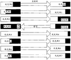
- the QCN mechanism and the PFC mechanism are applied together, the network node E supports the QCN mechanism and the PFC mechanism; A and D, B and D, D and E, C and E, and F and E use PFC mechanism for flow control .
- the working principle of the method in the first embodiment of the present invention is described in detail below with reference to the flow diagram 6.
- S601 The PFC mechanism on the node E starts to work, that is, the node E performs PFC detection on the ingress port.
- the node E detects that the ingress port is congested it marks the flow ID of the data flow Flow1 that caused the congestion, that is, FID1, and generates a PFC as shown in FIG.
- the node E continues to perform PFC detection on the ingress port.
- node E If congestion occurs on Flow1 in the set period T, and the number n of congestions of Flow1 is detected, node E generates PFC ⁇ , and sends the generated PFC ⁇ to the node along the uplink direction of the data flow Flow1.
- the upstream node of E is node D.
- the value of the Flow ID field in the PFC is FID1, and the value in the Times field is n. If n is smaller than the pre-set N_Red, the value of the Label field is Green. If n is greater than N_Red, the value of the Label field is Red.
- the PFC mechanism on the node D does not detect that Flow1 is congested during the pause period, and the node D restores the data on the data stream Flow1 to the node E.
- the node D restores the data on the data stream Flow1 to the node E.
- the node D after the pause period ends, the node D also resumes transmitting the data on the data stream Flow1 to the node E; of course, the data transmission on the Flow1 can be resumed at the same time as or before the node D sends the CNM message. As long as it is after the end of the suspension period.
- the node D pauses to send the data on the Flow1 to the node E during the set pause period, and adopts the pause mechanism in the PFC mechanism.
- the backpressure enable vector Prioirty enable vector of the PFC frame will be the best for Flow1.
- the E(N) corresponding to the priority queue N is set to 1, and the pause period Time(N) is set.
- the node E pauses the data transmission of the priority queue N, and the duration is Time (N); therefore, other data streams of the priority queue N are also suspended.
- the node D restores the data transmission of the priority queue N, including the data transmission of the above data stream Flow1.
- the congestion of the data stream is detected by using the PFC mechanism on the ingress port of the network node, and corresponding processing is performed according to the severity of the congestion: the number of congestions of a certain data flow does not exceed the set value within a set period.
- the congestion condition is sent to the uplink network node in the reverse direction of the data stream through the PFC, and the uplink network node pauses to send the data of the data stream during the pause period, thereby slowing local congestion, and when the uplink network node is suspended.
- the source terminal of the data stream is notified by the QCN flow control mechanism to reduce the transmission rate of the data stream.
- the uplink network node pauses to send the data stream.
- the source terminal of the data stream can be notified by the QCN flow control mechanism to reduce the transmission rate of the data stream.
- the source terminal receives the CNM message, it also starts a timer for determining whether the congestion condition is alleviated within the set recovery period; if the congestion is relieved, the transmission rate before the data stream is restored.
- multiple network nodes may notify the source terminal to reduce the transmission rate of the same data stream in the above recovery period (as in the first embodiment, if congestion occurs, node A, node D, and node E are both The source terminal is notified to reduce the transmission rate of the data stream Flow1.
- the source terminal reduces the transmission rate of the data stream when receiving the CNM message for the first time, and the source terminal may not further forward the CNM message received again during the recovery period. The rate is reduced, but the above recovery period is extended.
- the network node that performs the PFC mechanism detection on the ingress port detects that the number of congestions of a certain data stream exceeds a set value within a set period
- the network node sends the network node.
- the PFC frame is sent to the uplink network node, and the uplink network node pauses to transmit the data of the data stream.
- the uplink network node sends a CNM message to notify the source terminal of the data stream to reduce the data stream transmission rate through the QCN flow control mechanism.
- the network node that performs the PFC mechanism detection on the ingress port may also send the PFC frame to the uplink network.
- the network node causes the uplink network node to suspend transmission of data of the data stream; on the other hand, the network node directly sends a CNM message to the source terminal of the data stream to notify the source terminal to reduce the transmission rate of the data stream.
- the PFC structure of Fig. 4 can be further improved and applied to the embodiments illustrated in Figs. 5 and 6 above, as well as to all other embodiments of the present invention.
- the PFC can only include the Flow Identifier and Label fields, and does not include the Times field. It can also include only the Flow Identifier and Times fields, and does not include the Label field.
- the node E only needs to record the number of times of congestion on Flow1 in the period T. n, you do not need to set N_Red and compare with n.
- the times field in the received PFC ⁇ (that is, the number of times that node E detects congestion on Flow1 in period T).
- n the node D detects the degree of congestion and the degree of congestion on the Flow1 by the PFC mechanism during the pause period to determine the degree of the race of the flow1 and determine the operation of the node D, such as n+m is greater than the set value to trigger the QCN flow.
- the control mechanism sends a CNM message; or the CNM message may be sent when m is greater than the set value to trigger the QCN flow control mechanism.
- the PFC ⁇ can also include only the Flow Identifier field, and does not include the Label and Times fields.
- the node D After the node D receives the PFC sent by the node E, the node D only detects whether congestion and congestion occur on the Flow1 through the PFC mechanism during the pause period.
- the number m is used to determine the degree of the game of the flow1 and determine the operation of the node D. If the value of m is greater than the set value, the QCN flow control mechanism is triggered to send the CNM message, or the number of times the flow1 is congested during the pause period may not be recorded. Send a CNM message.
- Embodiment 2 of the present invention provides a method for congestion control, including:
- the first network node performs priority-based flow control (PFC) detection on the ingress port, and detects that a certain data flow, such as Flow1, is congested within the set detection period, and obtains the flow identifier of Flow1.
- PFC priority-based flow control
- the first network node generates a PFC frame and sends the PFC frame to the second network node, where the flow identifier Flow ID of Flow1 is included;
- the second network node performs congestion control on Flow1.
- the foregoing PFC frame further includes congestion degree information
- the second network node is configured to perform congestion control on the Flow1 according to the congestion degree information.
- the congestion degree information is a parameter used to indicate the congestion severity of the data flow Flow1.
- it may be expressed by a Label field or a Times field, or may be expressed by a Label field and a Times field.
- the congestion can be first relieved by locally suspending the transmission of the data stream; of course, the number of congestions on Flow1 in the period T can be directly used. Judging the severity of congestion, the larger the value of n, the more serious the congestion.
- the second network node performing congestion control on the flow1 according to the congestion degree information may include:
- the second network node sends a congestion notification message (CNM) to the source terminal of the data flow Flow1, and notifies the source terminal to reduce the transmission rate of the data flow Flow1; or
- CCM congestion notification message
- the second network node When the congestion degree information indicates that the congestion is light, the second network node pauses to send the data of the data stream Flow1 to the first network node during the set pause period; the second network node may also enter the port pair data stream during the pause period.
- Flow1 performs PFC detection: If the PFC detects that the data flow Flow1 is congested during the suspension period, the second network node may send a CNM message to the source terminal of the data flow Flow1, and notify the source terminal to reduce the transmission rate of the data flow Flow1.
- the second network node resumes transmitting data of the data stream Flow1 to the first network node.
- the first network node detects that the data flow Flow1 is seriously congested during the detection period (for example, when the number of congestions exceeds a set value or the cache occupancy rate is too high), the CNM message may be directly sent to the source of the data flow Flow1.
- the terminal notifies the source terminal to reduce the transmission rate of the data stream.
- the first embodiment and the second embodiment of the present invention improve the existing PFC mechanism and the PFC structure, so that when the network node performs the PFC mechanism detection, it can determine congestion detection of a specific data stream that is congested, and The congestion degree information is sent to the uplink node through the improved PFC.
- the congestion is not serious, the transmission rate of the data stream is locally reduced first to alleviate the congestion; when the data stream still has congestion after the congestion is severe or the local congestion is congested, the source terminal of the data flow is notified by the QCN flow control mechanism to reduce the data. The rate at which the stream is sent.
- the data stream can be flexibly processed according to the congestion condition, which can effectively cope with the problem of network data traffic change and congestion spread, and improve the efficiency of the entire network system.
- Embodiment 3 of the present invention provides a network node 700, as shown in FIG.
- the network node 700 includes:
- the detecting module 701 is configured to perform priority-based flow control (PFC) detection on the ingress port, such as detecting that a certain data stream, such as Flow1, is congested within the set detection period, and obtaining the data stream.
- PFC priority-based flow control
- the PFC frame generating module 703 is configured to generate a PFC frame, where the flow identifier of the data stream Flow1 obtained by the detecting module 701 is included;
- the PFC frame sending module 705 is configured to send a PFC frame generated by the PFC frame generating module 703, where the PFC frame is used to indicate that the network node that receives the PFC frame performs congestion control on the data stream Flow1.
- the foregoing PFC frame further includes congestion degree information.
- the congestion degree information is a parameter indicating the congestion severity of the data flow Flow1.
- it may be expressed by a Label field or a Times field, or may be expressed by a Label field and a Times field.
- the congestion can be alleviated by locally suspending the transmission of the data stream; of course, the number of times of congestion on Flow1 can be directly used in the set detection period.
- n to determine the severity of congestion, the greater the value of n, the more serious congestion.
- the network node may further include a CNM message sending module 707, configured to detect that the data flow Flow1 is severely congested during the detection period (for example, the number of times of congestion exceeds a set value or is slow When the storage occupancy rate is too high, the source terminal that sends the CNM message to the data stream notifies the source terminal to reduce the transmission rate of the data stream.
- a CNM message sending module 707 configured to detect that the data flow Flow1 is severely congested during the detection period (for example, the number of times of congestion exceeds a set value or is slow
- the source terminal that sends the CNM message to the data stream notifies the source terminal to reduce the transmission rate of the data stream.
- the network node provided in the foregoing Embodiment 3 of the present invention can identify which data stream is congested and provide it to other network nodes to perform more flexible congestion control on the data stream; further, the congestion degree information can be sent to The uplink node firstly reduces the transmission rate of the data stream to reduce congestion when the congestion is not serious; when the data stream still appears to be congested after the congestion is severe or the local congestion is congested, the source terminal of the data flow is notified by the QCN mechanism to reduce the data transmission rate. .
- the data stream is flexibly processed according to the congestion condition, which can effectively cope with the problem of network data traffic change and congestion spread, and improve the efficiency of the entire network system.
- Embodiment 4 of the present invention provides a network node 800, as shown in FIG.
- the network node 800 includes:
- the receiving module 801 is configured to receive a priority-based flow control (PFC) frame, where the PFC frame includes a flow identifier of a certain data flow, such as Flow1;
- PFC priority-based flow control
- the congestion control module 803 is configured to perform congestion control on the data flow Flow1 according to the PFC frame received by the receiving module 801.
- the PFC frame may further include congestion degree information; the congestion control module 803 performs congestion control on the data flow Flow1 according to the congestion degree information.
- the congestion degree information is a parameter indicating the congestion severity of the data flow Flow1.
- it may be expressed by a Label field or a Times field, or may be expressed by a Label field and a Times field.
- the congestion can be first relieved by locally suspending the transmission of the data stream; of course, the number of times of congestion on the data flow Flow1 during the detection period can be directly used.
- the severity of congestion the larger the value of n, the more serious the congestion.
- the optional congestion control module 803 can also be used to suspend the transmission during the set pause period.
- the network node 800 may further include: a sending module 805.
- the congestion control module 803 is further configured to perform PFC detection on the data stream Flow1 at the ingress port during the pause period; if the data stream Flow1 is detected to be congested during the pause period, the sending module 805 is configured to send a congestion notification message (Congestion Notification Message, CNM) to the source terminal of the data stream Flow1, notifying the source terminal to reduce the transmission rate of the data stream Flow1.
- CNM Congestion Notification Message
- the congestion control module 803 resumes transmitting the data of the data stream Flow1.
- the network node provided in the foregoing Embodiment 4 of the present invention can identify which data stream is congested according to the received PFC frame, and perform more flexible congestion control on the data flow according to the degree of congestion: firstly when the congestion is not serious The transmission rate of the data stream is reduced to alleviate the congestion; when the data stream still has congestion after the congestion is severe or the local congestion is congested, the source terminal of the data stream is notified by the QCN mechanism to reduce the data transmission rate.
- the data stream is flexibly processed according to the congestion condition, which can effectively cope with the problem of network data traffic change and congestion spread, and improve the efficiency of the entire network system.
- Embodiment 5 of the present invention provides a congestion control system. As shown in FIG. 9, the system includes a first network node and a second network node.
- the first network node performs priority-based flow control (PFC) detection on the ingress port, and if a certain data stream, such as Flow1, is detected to be congested within a set detection period, the data stream is acquired. Flow ID of Flow1.
- the first network node generates a PFC frame including the flow identifier of the data stream Flow1, and transmits the PFC frame to the second network node.
- PFC priority-based flow control
- the second network node performs congestion control on the data flow Flow1 according to the PFC.
- the PFC frame may further include congestion degree information; and the second network node performs congestion control on the data flow Flow1 according to the congestion degree information.
- the second network node according to the congestion control on the data flow Flow1 may include:
- the second network node is configured to send a Congestion Notification Message (CNM) to the source terminal of the data flow Flow1, and notify the source terminal to reduce the transmission rate of the data flow Flow1.
- CCM Congestion Notification Message
- the second network node according to the congestion control of the data flow Flow1 may further include: the second network node suspending sending the data of the data flow Flow1 to the first network node during the set pause period.
- the second network node may further perform PFC detection on the data flow Flow1 at the ingress port during the pause period;
- the second network node If the data flow Flow1 is congested during the suspension period, the second network node sends a CNM message to the source terminal of the data flow Flow1, informing the source terminal to decrease the transmission rate of the data flow.
- the second network node resumes transmitting data of the data stream Flow1 to the first network node.
- the first network node may directly send the CNM message to the data stream when detecting that a serious congestion occurs in the set detection period (for example, when the number of congestion of the data flow Flow1 exceeds a set value or the cache occupancy rate is too high)
- the source terminal notifies the source terminal to reduce the transmission rate of the data stream.
- the congestion control system provided in the above fifth embodiment of the present invention can identify which data stream is sent. Congestion occurs and more flexible congestion control is performed according to the degree of congestion: when the congestion is not serious, the transmission rate of the data stream is locally reduced to alleviate the congestion; when the data stream still has congestion after the congestion is severe or the local congestion is congested, the notification is notified through the QCN mechanism.
- the source terminal of the data stream reduces the transmission rate of the data stream.
- the data stream is flexibly processed according to the congestion condition, which can effectively cope with the problem of network data traffic change and congestion spread, and improve the efficiency of the entire network system.
- Computer readable media includes both computer storage media and communication media including any medium that facilitates transfer of a computer program from one location to another.
- a storage medium may be any available media that can be accessed by a computer.
- computer readable media may comprise RAM, ROM, EEPROM, CD-ROM or other optical disk storage, disk storage media or other magnetic storage device, or can be used for carrying or storing in the form of an instruction or data structure.
- connection may suitably be a computer readable medium.
- the software is transmitted from a website, server, or other remote source using coaxial cable, fiber optic cable, twisted pair, digital subscriber line (DSL), or wireless technologies such as infrared, radio, and microwave
- coaxial cable , fiber optic cable, twisted pair, DSL, or wireless technologies such as infrared, wireless, and microwave are included in the fixing of the associated media.
- a disk and a disc include a compact disc (CD), a laser disc, a compact disc, a digital versatile disc (DVD), a floppy disk, and a Blu-ray disc, wherein the disc is usually magnetically copied, and the disc is The laser is used to optically replicate the data. Combinations of the above should also be included within the scope of the computer readable media.
Abstract
Disclosed in an embodiment of the present invention is a congestion control method, comprising: a first network node conducts a priority-based flow control (PFC) detection for an inlet port, and if a data flow occurring congestion within a set detection period is detected, a flow identification of the data flow is obtained; the first network node generates a PFC frame comprising the flow identification of the data flow, and transmits the PFC frame to a second network node, so as to instruct the second network node to conduct the congestion control for the data flow. The embodiment of the present invention enables the PFC mechanism to conduct the congestion detection for the specific data flow by improving the existing PFC mechanism, transmits the congestion level to an uplink node via the improved PFC frame, and flexibly processes the data flow according to a congestion situation, thus effectively handling with the problems of the change of network data traffic and congestion diffusion, and improving efficiency of the whole network system. Also disclosed in the embodiment of the present invention are a network node, system and computer readable medium.
Description
本发明实施例涉及网络领域,尤其涉及一种拥塞控制的方法、设备和系统。The embodiments of the present invention relate to the field of networks, and in particular, to a method, device, and system for congestion control.
以太网(Ethernet)是一种计算机局域网组网技术。IEEE制定的IEEE 802.3标准给出了以太网的技术标准,它规定了包括物理层的连线、电信号和介质访问层协议的内容。以太网是当前应用最普遍的局域网技术。Ethernet (Ethernet) is a computer LAN networking technology. The IEEE 802.3 standard developed by the IEEE gives the technical standard for Ethernet, which specifies the contents of the connection, electrical signals, and medium access layer protocols including the physical layer. Ethernet is the most common LAN technology in current applications.
为解决以太网中出现拥塞时可能导致的丢包现象,目前已经制定了多项用于保障无损以太网的技术,包括量化拥塞通知(Quantized Congestion Notification,简称为QCN)协议和基于优先级的流控(Priority-based Flow Control,简称为PFC)机制。To solve the packet loss caused by congestion in Ethernet, a number of technologies for securing lossless Ethernet have been developed, including Quantized Congestion Notification (QCN) protocol and priority-based flow. Priority-based Flow Control (PFC) mechanism.
图1是现有技术中QCN机制的工作原理示意图。QCN协议采用量化拥塞控制技术,相对于其他拥塞控制技术采用了相对精准的后向拥塞通知机制。在网络中的设备也被称之为网络节点;在网络节点上基于出端口队列设置拥塞检测点,即对网络节点上向外发出数据的缓存队列进行拥塞检测。如果网络节点检测到有拥塞发生时,则生成拥塞通知消息(Congestion Notification Message,简称为CNM),其中包含指示导致拥塞的流(Flow)的标识信息和拥塞程度的信息;网络节点将生成的CNM消息沿着流传输的反方向发送到导致拥塞的源终端,由源终端根据CNM消息降低相应流的数据发送速率。FIG. 1 is a schematic diagram of the working principle of the QCN mechanism in the prior art. The QCN protocol uses quantitative congestion control technology and uses a relatively accurate backward congestion notification mechanism compared to other congestion control technologies. The devices in the network are also referred to as network nodes; the congestion detection points are set on the network nodes based on the outbound port queues, that is, the congestion detection is performed on the cache queues that send out data on the network nodes. If the network node detects that congestion occurs, a congestion notification message (CNM) is generated, which includes information indicating the identification information of the flow causing the congestion and the degree of congestion; the CNM generated by the network node The message is sent along the reverse direction of the streaming to the source terminal that causes congestion, and the source terminal reduces the data transmission rate of the corresponding stream according to the CNM message.
图2是现有技术中PFC机制的工作原理示意图。支持PFC机制的节点将入端口队列上的数据流按照802.1Q协议规定的VLAN tag的优先级字段分为8个优先级队列,一旦检测到某优先级队列(比如图2中的优先级队列3)的流量过多导致拥塞,则接收端暂停该优先级队列3上的数据接收,发送端停止该优先级队列3上的数据发送。
2 is a schematic diagram of the working principle of the PFC mechanism in the prior art. A node that supports the PFC mechanism divides the data stream on the inbound port queue into eight priority queues according to the priority field of the VLAN tag specified by the 802.1Q protocol. Once a priority queue is detected (such as the priority queue 3 in Figure 2) If the excessive traffic causes congestion, the receiving end pauses the data reception on the priority queue 3, and the transmitting end stops the data transmission on the priority queue 3.
在实际网络中,一般将QCN协议和PFC机制结合起来使用,如图3所示。网络节点E支持QCN协议和PFC机制;A与D,B与D,D与E,C与E,及F与E之间采用PFC机制进行流量控制。在各节点上会相应设置触发PFC机制及触发QCN机制的阈值。In the actual network, the QCN protocol and the PFC mechanism are generally used together, as shown in FIG. Network node E supports QCN protocol and PFC mechanism; A and D, B and D, D and E, C and E, and F and E use PFC mechanism for flow control. The thresholds for triggering the PFC mechanism and triggering the QCN mechanism are set on each node.
举例来说,在节点E上,出端口队列缓存大小是500K字节,入端口队列缓存大小是100K字节。在节点E上,将触发QCN机制(即对出端口发送数据的速率进行流量控制)的阈值可设置为20%,即一旦出端口缓存占用率超过20%(即超过100k字节),节点E会启动QCN机制,对出端口发送数据的速率进行控制。For example, on node E, the outbound port queue buffer size is 500K bytes, and the ingress port queue buffer size is 100K bytes. On node E, the threshold for triggering the QCN mechanism (that is, the flow rate of the rate at which the outbound port sends data) can be set to 20%, that is, once the outbound port cache occupancy exceeds 20% (that is, exceeds 100 kbytes), node E The QCN mechanism is activated to control the rate at which the outgoing port sends data.
PFC机制作用于入端口,在节点E上将触发PFC机制(即对入端口接收数据的速率进行流量控制)的阈值可设置为80%,即一旦入端口缓存占用率超过了80%(即超过80K字节),节点E会启动PFC机制,对入端口接收数据的速率进行控制。如节点E检测到如图2中的某优先级队列的流量过多导致拥塞,则暂停该优先级队列上的数据接收。The PFC machine is configured to be used for the ingress port. The threshold for triggering the PFC mechanism on the node E (that is, the flow rate control of the rate at which the inbound port receives data) can be set to 80%, that is, once the inbound port cache occupancy rate exceeds 80% (that is, 80K bytes), node E will start the PFC mechanism to control the rate at which the inbound port receives data. If the node E detects congestion caused by too much traffic of a certain priority queue as in FIG. 2, the data reception on the priority queue is suspended.
当节点E上设置的触发PFC机制的阈值过低时,则节点E则很容易触发PFC机制,从而导致节点E降低入端口接收数据的速率,也就是节点C、D、F上出端口向节点E发送数据的速率。这样情况下,节点E的出端口可能永远不会产生拥塞,其上的QCN机制的流控功能就不会启动;从而导致了节点之间的链路利用率过低。When the threshold of the triggered PFC mechanism set on the node E is too low, the node E can easily trigger the PFC mechanism, thereby causing the node E to reduce the rate at which the inbound port receives data, that is, the nodes C, D, and F go to the port to the node. E The rate at which data is sent. In this case, the egress port of the node E may never be congested, and the flow control function of the QCN mechanism on it will not be started; thus, the link utilization between the nodes is too low.
如果节点E上长时间拥塞,使得节点E上的入端口队列长时间被100%暂用,则节点E向节点D、F或C请求降低发送数据的速率。以节点E向节点D请求降低节点D向节点E发送数据的速率为例,一旦节点D向节点E发送数据的速率降下来,但暂时节点D上入端口接收数据的速率降不下来,则会导致节点D入端口的拥塞,实质上可以看作是节点E将入端口的拥塞扩散到节点D;并可能继续往上一级节点如节点A或节点B扩散。If the node E is congested for a long time, so that the ingress port queue on the node E is temporarily used 100%, the node E requests the node D, F or C to reduce the rate of transmitting data. For example, the node E requests the node D to reduce the rate at which the node D sends data to the node E. Once the rate at which the node D sends data to the node E is lowered, but the rate at which the inbound port of the temporary node D receives data cannot be lowered, The congestion caused by the ingress of the node D can be regarded as the fact that the node E spreads the congestion of the ingress port to the node D; and may continue to spread to the upper level node such as the node A or the node B.
当节点E上设置的触发PFC机制的阈值过高时,则其上的QCN机制会被先触发,使得相应数据流的源终端发送数据的速率降低;而此时节点E上触发PFC
机制的阈值尚未达到,则节点E并不启动PFC机制的流量控制功能。节点E启动QCN机制后,如检测到拥塞则会生成CNM消息并发送到导致拥塞的源终端。但该过程需经过网络中的多个节点,在节点E发送CNM消息到源终端降低发送数据的速率的这段时间内,节点E处的出端口发送数据的速率被控制,但PFC机制尚未启动,则短时间内节点E不会控制入端口的接收数据的速率,导致节点E的出端口拥塞更加严重。When the threshold of the triggered PFC mechanism set on the node E is too high, the QCN mechanism on the node is triggered first, so that the rate at which the source terminal of the corresponding data stream transmits data decreases; and at this time, the PFC is triggered on the node E.
If the threshold of the mechanism has not been reached, node E does not start the flow control function of the PFC mechanism. After the node E starts the QCN mechanism, if congestion is detected, a CNM message is generated and sent to the source terminal that causes congestion. However, the process needs to pass through multiple nodes in the network. During the period in which the node E sends the CNM message to the source terminal to reduce the rate of sending data, the rate at which the outbound port at the node E sends data is controlled, but the PFC mechanism has not been started. In the short time, the node E does not control the rate of receiving data at the ingress port, which causes the congestion of the egress port of the node E to be more serious.
现有技术通过设置阈值的方式使QCN机制和PFC机制互相配合工作。然而如上所述,一旦阈值设置不合理则很可能导致拥塞扩散或者拥塞加重,降低整个网络系统的效率。另外,由于网络上数据流量的复杂性和不可预测性,固定设置阈值的方式并不能有效应对网络数据流量的变化,不能灵活解决拥塞控制的问题。In the prior art, the QCN mechanism and the PFC mechanism work together by setting a threshold. However, as described above, once the threshold setting is unreasonable, it is likely to cause congestion spread or congestion, which reduces the efficiency of the entire network system. In addition, due to the complexity and unpredictability of data traffic on the network, the fixed threshold setting method cannot effectively respond to changes in network data traffic, and cannot solve the problem of congestion control flexibly.
发明内容Summary of the invention
有鉴于此,本发明实施例提供了一种拥塞控制的方法、设备和系统,能有效应对网络数据流量的变化,从而灵活解决拥塞控制的问题。In view of this, the embodiments of the present invention provide a method, a device, and a system for congestion control, which can effectively cope with changes in network data traffic, thereby flexibly solving the problem of congestion control.
第一方面,本发明实施例提供了一种拥塞控制的方法,包括:In a first aspect, an embodiment of the present invention provides a method for congestion control, including:
第一网络节点对入端口进行基于优先级的流控(Priority-based Flow Control,PFC)检测,如在设定的检测周期内检测到某一数据流发生拥塞,获得该数据流的流标识;The first network node performs priority-based flow control (PFC) detection on the ingress port, for example, detecting that a certain data stream is congested within the set detection period, and obtaining a flow identifier of the data stream;
所述第一网络节点生成PFC帧,所述PFC帧包括所述数据流的流标识;Generating, by the first network node, a PFC frame, where the PFC frame includes a flow identifier of the data stream;
所述第一网络节点发送所述PFC帧到第二网络节点,指示所述第二网络节点对所述数据流进行拥塞控制。The first network node sends the PFC frame to a second network node, instructing the second network node to perform congestion control on the data flow.
第二方面,本发明实施例还提供了一种拥塞控制的方法,包括:In a second aspect, the embodiment of the present invention further provides a method for congestion control, including:
网络节点接收基于优先级的流控(Priority-based Flow Control,PFC)帧,所述PFC帧包括所述数据流的流标识;
The network node receives a priority-based flow control (PFC) frame, where the PFC frame includes a flow identifier of the data stream;
所述网络节点根据所述PFC帧对所述数据流进行拥塞控制。The network node performs congestion control on the data stream according to the PFC frame.
第三方面,本发明实施例还提供了一种网络节点,包括:In a third aspect, an embodiment of the present invention further provides a network node, including:
检测模块,用于对入端口进行基于优先级的流控(Priority-based Flow Control,PFC)检测,如在设定的检测周期内检测到某一数据流发生拥塞,获得所述数据流的流标识;The detection module is configured to perform priority-based flow control (PFC) detection on the ingress port, such as detecting that a certain data stream is congested within a set detection period, and obtaining a flow of the data stream. Identification
PFC帧生成模块,用于生成PFC帧,所述PFC帧包括所述数据流的流标识;a PFC frame generating module, configured to generate a PFC frame, where the PFC frame includes a stream identifier of the data stream;
PFC帧发送模块,用于发送所述PFC帧,所述PFC帧用于指示接收该PFC帧的网络节点对所述数据流进行拥塞控制。The PFC frame sending module is configured to send the PFC frame, where the PFC frame is used to indicate that the network node that receives the PFC frame performs congestion control on the data stream.
第四方面,本发明实施例还提供了一种网络节点,包括:In a fourth aspect, the embodiment of the present invention further provides a network node, including:
接收模块,用于接收基于优先级的流控(Priority-based Flow Control,PFC)帧,所述PFC帧包括某一数据流的流标识;a receiving module, configured to receive a priority-based flow control (PFC) frame, where the PFC frame includes a flow identifier of a certain data stream;
拥塞控制模块,用于根据所述PFC帧对所述数据流进行拥塞控制。a congestion control module, configured to perform congestion control on the data flow according to the PFC frame.
第五方面,本发明实施例还提供了一种拥塞控制系统,包括第一网络节点和第二网络节点;In a fifth aspect, an embodiment of the present invention further provides a congestion control system, including a first network node and a second network node;
所述第一网络节点,用于对入端口进行基于优先级的流控(Priority-based Flow Control,PFC)检测,如在设定的检测周期内检测到某一数据流发生拥塞,获得该数据流的流标识;所述第一网络节点用于生成包含所述数据流的流标识的PFC帧,并发送所述PFC帧到所述第二网络节点;The first network node is configured to perform priority-based flow control (PFC) detection on the ingress port, such as detecting congestion of a certain data flow in the set detection period, and obtaining the data. a flow identifier of the flow; the first network node is configured to generate a PFC frame that includes a flow identifier of the data flow, and send the PFC frame to the second network node;
所述第二网络节点,用于对所述数据流进行拥塞控制。The second network node is configured to perform congestion control on the data flow.
第六方面,本发明实施例还提供了一种网络节点,包括处理器和存储器,
所述存储器存储执行指令,当所述网络节点运行时,所述处理器与所述存储器之间通信,所述处理器执行所述执行指令使所述网络节点执行上述第一方面的方法。In a sixth aspect, an embodiment of the present invention further provides a network node, including a processor and a memory.
The memory stores execution instructions that, when the network node is running, communicate with the memory, the processor executing the execution instructions to cause the network node to perform the method of the first aspect above.
第七方面,本发明实施例还提供了一种网络节点,包括处理器和存储器,所述存储器存储执行指令,当所述网络节点运行时,所述处理器与所述存储器之间通信,所述处理器执行所述执行指令使得所述网络执行上述第二方面的方法。In a seventh aspect, an embodiment of the present invention further provides a network node, including a processor and a memory, where the memory stores an execution instruction, and when the network node is running, the processor communicates with the memory, where Executing the execution instructions by the processor causes the network to perform the method of the second aspect above.
第八方面,本发明实施例还提供了一种计算机可读介质,包含计算机执行指令,所述计算机执行指令用于使主机执行上述第一方面的方法。In an eighth aspect, an embodiment of the present invention further provides a computer readable medium, comprising computer execution instructions, for causing a host to perform the method of the above first aspect.
第九方面,本发明实施例还提供了一种计算机可读介质,包含计算机执行指令,所述计算机执行指令用于使主机执行上述第二方面的方法。In a ninth aspect, the embodiment of the present invention further provides a computer readable medium, comprising computer execution instructions, wherein the computer execution instructions are used to cause a host to perform the method of the second aspect.
本发明实施例通过在对现有的PFC机制进行改进,使得PFC机制能对某条具体的数据流进行拥塞检测,并将拥塞程度通过改进后的PFC桢发送给上行节点,可根据拥塞情况对数据流进行灵活处理,可以有效应对网络数据流量的变化和拥塞扩散的问题,提高了整个网络系统的效率。The embodiment of the present invention improves the existing PFC mechanism, so that the PFC mechanism can perform congestion detection on a specific data flow, and the congestion degree is sent to the uplink node through the improved PFC, which can be based on the congestion situation. Flexible processing of data streams can effectively cope with changes in network data traffic and congestion and increase the efficiency of the entire network system.
为了更清楚地说明本发明实施例的技术方案,下面将对实施例描述中所需要使用的附图作简单地介绍,显而易见地,下面描述中的附图仅仅是本发明的一些实施例,对于本领域普通技术人员来讲,在不付出创造性劳动的前提下,还可以根据这些附图获得其他的附图。In order to more clearly illustrate the technical solutions of the embodiments of the present invention, the drawings used in the description of the embodiments will be briefly described below. It is obvious that the drawings in the following description are only some embodiments of the present invention, Those skilled in the art can also obtain other drawings based on these drawings without paying any creative work.
图1为现有技术中QCN机制的工作原理示意图;1 is a schematic diagram showing the working principle of a QCN mechanism in the prior art;
图2为现有技术中PFC机制的工作原理示意图;
2 is a schematic diagram of a working principle of a PFC mechanism in the prior art;
图3为现有技术中QCN机制和PFC机制共同应用的工作原理示意图;3 is a schematic diagram of a working principle of a common application of a QCN mechanism and a PFC mechanism in the prior art;
图4为本发明实施例对PFC桢结构的改进示意图;4 is a schematic diagram of an improvement of a PFC structure according to an embodiment of the present invention;
图5为本发明实施例一的工作原理示意图;FIG. 5 is a schematic diagram of a working principle of Embodiment 1 of the present invention; FIG.
图6为本发明实施例一的方法流程示意图;FIG. 6 is a schematic flowchart of a method according to Embodiment 1 of the present invention; FIG.
图7为本发明实施例三的网络节点结构示意图;7 is a schematic structural diagram of a network node according to Embodiment 3 of the present invention;
图8为本发明实施例四的网络节点结构示意图;8 is a schematic structural diagram of a network node according to Embodiment 4 of the present invention;
图9为本发明实施例五的系统结构示意图。FIG. 9 is a schematic structural diagram of a system according to Embodiment 5 of the present invention.
下面将结合本发明实施例中的附图,对本发明实施例中的技术方案进行清楚、完整地描述,显然,所描述的实施例是本发明一部分实施例,而不是全部的实施例。基于本发明中的实施例,本领域普通技术人员在没有作出创造性劳动前提下所获得的所有其他实施例,都属于本发明保护的范围。The technical solutions in the embodiments of the present invention are clearly and completely described in the following with reference to the accompanying drawings in the embodiments of the present invention. It is obvious that the described embodiments are a part of the embodiments of the present invention, but not all embodiments. All other embodiments obtained by those skilled in the art based on the embodiments of the present invention without creative efforts are within the scope of the present invention.
如图4所示,是本发明实施例对现有的PFC桢结构的一种改进。现有的PFC桢中包括如下字段:As shown in FIG. 4, it is an improvement of the existing PFC structure in the embodiment of the present invention. The existing PFC桢 includes the following fields:
Destination address:6字节,用于标示数据桢的目的MAC地址。Destination address: 6 bytes, used to indicate the destination MAC address of the data port.
Source address:6字节,用于标示数据桢的源MAC地址。Source address: 6 bytes, used to indicate the source MAC address of the data port.
Ethetype:2字节,用于标示桢的类型。Ethetype: 2 bytes, used to indicate the type of 桢.
Control opcode:2字节,用于标示控制码。Control opcode: 2 bytes, used to indicate the control code.
Prioirty enable vector:2字节,表示为反压使能向量,:其中第1个字节直接设置为0;第2个字节E(N)的8位分别与PFC机制中定义的8个优先级队列对应,表示指示是否需要暂停发送优先级队列N上的数据;当E(N)=1时表示需要暂停发送优先级队列N上的数据,暂停的时间为接下来的Time(N);当E(N)=0时表示不需要暂停发送优先级队列N上的数据。Prioirty enable vector: 2 bytes, expressed as backpressure enable vector, where the first byte is directly set to 0; the second byte of E(N) is 8 bits respectively defined in the PFC mechanism. Corresponding to the level queue, indicating whether it is necessary to suspend the transmission of data on the priority queue N; when E(N)=1, it indicates that the data on the priority queue N needs to be suspended, and the pause time is the next Time(N); When E(N) = 0, it means that it is not necessary to suspend the transmission of data on the priority queue N.
Time(0)-Time(7):各2字节,为暂停定时器,指示暂停相应优先级队列的数据发送的时长,其单位可以是以当前物理芯片的传输速率传输512位数据所用的时间;比如Priority enable vector中的E(3)=1且Time(3)=8,该PFC帧指示的是暂停优先级队列3上的数据发送,暂停时长是以当前物理芯片的传输速率发送8*512=4096位的数据所需的时间。
Time(0)-Time(7): each 2 bytes, which is a pause timer, indicating the duration of data transmission for suspending the corresponding priority queue. The unit can be the time used to transmit 512-bit data at the transmission rate of the current physical chip. For example, E(3)=1 and Time(3)=8 in the Priority enable vector, the PFC frame indicates the data transmission on the pause priority queue 3, and the pause duration is sent at the transmission rate of the current physical chip. The time required for 512=4096 bits of data.
Pad:预留字段,26字节。Pad: Reserved field, 26 bytes.
CRC:4字节,是循环冗余校验信息。CRC: 4 bytes, which is cyclic redundancy check information.
本发明实施例可在上述预留的Pad字段内增加如下信息:In the embodiment of the present invention, the following information may be added in the reserved Pad field:
Flow Identifier(简称Flow ID):2字节,为流标识;该Flow ID是(由支持QCN机制的终端分配的标识,可通过Flow ID找到源终端多条数据流导致拥塞的具体数据流);对于PFC机制来说,网络节点在检测到入端口产生拥塞时,可标记导致拥塞的数据流;Flow Identifier (Flow ID): 2 bytes, which is the flow identifier. The Flow ID is the identifier assigned by the terminal that supports the QCN mechanism. The flow ID can be used to find the specific data flow caused by multiple data streams of the source terminal. For the PFC mechanism, when detecting that the ingress port is congested, the network node may mark the data flow that causes congestion;
Times:2bit,指示在设定的周期内检测上述Flow ID对应的数据流发生拥塞的次数;Times: 2bit, indicating that the number of times the data stream corresponding to the Flow ID is congested is detected within a set period;
Label:1bit,标记当前的流控状态,取值可以为Red或Green(根据实际设计,Red可取值为0或1,相应地Green取值为1或0);如Label=Red,则指示接收到该PFC流控桢PFC桢的节点触发QCN流控机制;如Label=Green则暂不触发QCN流控机制。Label和Times是相关联的,一般是在节点上设置用于判断流控状态的N_Red,如果Times的取值超过N_Red,则Label=Green,否则Label=Red。Label: 1 bit, marking the current flow control state. The value can be Red or Green. According to the actual design, Red can take a value of 0 or 1, correspondingly Green is 1 or 0. If Label=Red, the indication is The node that receives the PFC flow control PFC桢 triggers the QCN flow control mechanism; if Label=Green, the QCN flow control mechanism is not triggered. Label and Times are associated. Generally, N_Red is set on the node to determine the flow control state. If the value of Times exceeds N_Red, Label=Green, otherwise Label=Red.
如图5所示,为本发明实施例一的工作原理示意图。该实施例中QCN机制和PFC机制共同应用,网络节点E支持QCN机制和PFC机制;A与D,B与D,D与E,C与E,及F与E之间采用PFC机制进行流量控制。在各节点上可以设置触发PFC机制的阈值和触发QCN机制的阈值,网络节点根据节点上的缓存使用情况和上述阈值来判断是否发生拥塞以及拥塞的严重程度。以图5所示源终端发送到目的终端的数据流Flow1(Flow ID=FID1)为例,该数据流经由节点A到D,并由节点E流向目的终端。下面结合流程示意图6详细阐述本发明实施例一的方法工作原理。FIG. 5 is a schematic diagram of the working principle of the first embodiment of the present invention. In this embodiment, the QCN mechanism and the PFC mechanism are applied together, the network node E supports the QCN mechanism and the PFC mechanism; A and D, B and D, D and E, C and E, and F and E use PFC mechanism for flow control . A threshold for triggering the PFC mechanism and a threshold for triggering the QCN mechanism may be set on each node, and the network node determines whether congestion occurs and the severity of congestion according to the cache usage on the node and the foregoing threshold. Taking the data flow Flow1 (Flow ID=FID1) sent from the source terminal to the destination terminal as shown in FIG. 5 as an example, the data stream flows through the nodes A to D and flows from the node E to the destination terminal. The working principle of the method in the first embodiment of the present invention is described in detail below with reference to the flow diagram 6.
S601:节点E上的PFC机制开始工作,即节点E对入端口进行PFC检测。节点E一旦检测到入端口发生拥塞,则会标记导致拥塞的数据流Flow1的Flow ID即FID1,并生成如图4所示的PFC桢。S601: The PFC mechanism on the node E starts to work, that is, the node E performs PFC detection on the ingress port. When the node E detects that the ingress port is congested, it marks the flow ID of the data flow Flow1 that caused the congestion, that is, FID1, and generates a PFC as shown in FIG.
若在设定周期T内未检测到入端口发生拥塞,则节点E继续在入端口进行PFC检测。
If congestion is not detected in the ingress port within the set period T, the node E continues to perform PFC detection on the ingress port.
S603:若在设定周期T内,Flow1上发生了拥塞,并检测Flow1发生拥塞的次数n,则节点E生成PFC桢,并沿着数据流Flow1的上行方向,将生成的PFC桢发送给节点E的上行节点即节点D。该PFC桢中的Flow ID字段取值为FID1,Times字段取值为n;如果n小于预先设置的N_Red,则Label字段取值为Green,如果n超过了N_Red,则Label字段取值为Red。S603: If congestion occurs on Flow1 in the set period T, and the number n of congestions of Flow1 is detected, node E generates PFC桢, and sends the generated PFC桢 to the node along the uplink direction of the data flow Flow1. The upstream node of E is node D. The value of the Flow ID field in the PFC is FID1, and the value in the Times field is n. If n is smaller than the pre-set N_Red, the value of the Label field is Green. If n is greater than N_Red, the value of the Label field is Red.
S605:当上述PFC桢中的Label=Green时,节点D在设置的时间内暂停向节点E发送Flow1上的数据,并对Flow1在入端口进行PFC检测。该设置的时间也称为暂停期间(即Pause Duration)。S605: When Label=Green in the PFC桢, the node D pauses to send the data on the Flow1 to the node E within the set time, and performs the PFC detection on the ingress port of the flow1. The time of this setting is also called the pause duration (ie Pause Duration).
S607:如果节点D上在暂停期间内检测到Flow1发生了拥塞,则节点D直接触发QCN流控机制,即节点D生成CNM消息并发送到数据流Flow1的源终端,通知源终端降低相应数据流Flow1的数据发送速率。S607: If the congestion of the Flow1 is detected on the node D during the pause period, the node D directly triggers the QCN flow control mechanism, that is, the node D generates a CNM message and sends the message to the source terminal of the data flow Flow1, informing the source terminal to reduce the corresponding data flow. Flow1 data transmission rate.
S609:如果节点E在周期T内检测到Flow1上拥塞的次数超过N_Red,即Label=Red时,节点D收到PFC桢后暂停向节点E发送Flow1上的数据,生成CNM消息并发送到数据流Flow1的源终端,通知源终端降低数据流Flow1的发送速率。S609: If the node E detects that the number of congestions on Flow1 exceeds N_Red in the period T, that is, Label=Red, after receiving the PFC, the node D pauses to send the data on the Flow1 to the node E, generates a CNM message, and sends the message to the data stream. The source terminal of Flow1 notifies the source terminal to reduce the transmission rate of the data stream Flow1.
S611:暂停期间结束后,节点D上会恢复向节点E发送数据流Flow1上的数据。S611: After the pause period ends, the data on the data stream Flow1 is sent back to the node E on the node D.
具体来说,节点D上的PFC机制在暂停期间内未检测到Flow1发生拥塞,节点D上会恢复向节点E发送数据流Flow1上的数据。上述S607或S609所示情形,在暂停期间结束后节点D也会恢复向节点E发送数据流Flow1上的数据;当然S611情形下恢复Flow1上数据发送可以在节点D发送CNM消息的同时或者之前,只要是暂停期间结束后即可。Specifically, the PFC mechanism on the node D does not detect that Flow1 is congested during the pause period, and the node D restores the data on the data stream Flow1 to the node E. In the case of the above S607 or S609, after the pause period ends, the node D also resumes transmitting the data on the data stream Flow1 to the node E; of course, the data transmission on the Flow1 can be resumed at the same time as or before the node D sends the CNM message. As long as it is after the end of the suspension period.
在恢复数据发送的同时,节点D和节点E都将清除之前记录的该Flow1上的Label标记和Times参数值。At the same time as the data transmission is resumed, both node D and node E will clear the previously marked Label and Times parameter values on the Flow1.
需要说明的是,本发明上述实施例中,节点D在设置的暂停期间内暂停向节点E发送Flow1上的数据,采用了PFC机制中的暂停机制。具体参见如图4所示改进的PFC桢结构:如果节点E需要节点D暂停Flow1上的数据流发送,PFC帧的反压使能向量Prioirty enable vector会将该Flow1所在的优
先级队列N对应的E(N)设置为1,并设置暂停期间Time(N)。节点E在接收到PFC帧后则会暂停该优先级队列N的数据发送,时长即为Time(N);因此该优先级队列N的其他数据流也会被暂停。在暂停期间Time(N)结束后,节点D会恢复该优先级队列N的数据发送,包括上述数据流Flow1的数据发送。It should be noted that, in the above embodiment of the present invention, the node D pauses to send the data on the Flow1 to the node E during the set pause period, and adopts the pause mechanism in the PFC mechanism. For details, refer to the improved PFC structure shown in Figure 4. If node E needs node D to suspend the data stream transmission on Flow1, the backpressure enable vector Prioirty enable vector of the PFC frame will be the best for Flow1.
The E(N) corresponding to the priority queue N is set to 1, and the pause period Time(N) is set. After receiving the PFC frame, the node E pauses the data transmission of the priority queue N, and the duration is Time (N); therefore, other data streams of the priority queue N are also suspended. After the end of the pause period Time(N), the node D restores the data transmission of the priority queue N, including the data transmission of the above data stream Flow1.
本发明实施例一通过在网络节点的入端口上通过PFC机制检测数据流的拥塞情况,根据拥塞的严重程度进行相应处理:在一设定周期内某条数据流导致拥塞次数未超过设定值时,将拥塞情况通过PFC桢沿数据流的反方向发送给上行网络节点,由该上行网络节点在暂停期间内先暂停发送该数据流的数据,减缓局部拥塞,并在当上行网络节点在暂停期间内检测到该数据流再次拥塞时直接,通过QCN流控机制通知数据流的源终端降低数据流的发送速率。In the first embodiment of the present invention, the congestion of the data stream is detected by using the PFC mechanism on the ingress port of the network node, and corresponding processing is performed according to the severity of the congestion: the number of congestions of a certain data flow does not exceed the set value within a set period. The congestion condition is sent to the uplink network node in the reverse direction of the data stream through the PFC, and the uplink network node pauses to send the data of the data stream during the pause period, thereby slowing local congestion, and when the uplink network node is suspended. When the data stream is detected to be congested again during the period, the source terminal of the data stream is notified by the QCN flow control mechanism to reduce the transmission rate of the data stream.
当然,若前述入端口进行PFC机制检测的网络节点在设定一周期内,检测到某条数据流导致拥塞次数超过设定值即拥塞已经较为严重时,上行网络节点在暂停发送该数据流的数据的同时,还可以通过QCN流控机制通知数据流的源终端降低数据流的发送速率。在实际业务中,源终端收到CNM消息时还会启动一定时器,用于在设定的恢复周期内判断拥塞情况是否缓解;如果拥塞缓解了则恢复该数据流之前的发送速率。在实际的网络环境下,可能有多个网络节点在上述恢复周期都通知源终端降低同一数据流的发送速率(如上述实施例一,若拥塞发生了扩散,节点A,节点D和节点E都通知了源终端降低数据流Flow1的发送速率),源终端在第1次收到CNM消息时会降低数据流的发送速率,而针对在恢复周期内再次接到的CNM消息,源终端可以不进一步降低速率,而是延长上述恢复周期。Of course, if the network node that performs the PFC mechanism detection on the ingress port detects that a certain data stream exceeds the set value, that is, the congestion is already serious, the uplink network node pauses to send the data stream. At the same time of data, the source terminal of the data stream can be notified by the QCN flow control mechanism to reduce the transmission rate of the data stream. In the actual service, when the source terminal receives the CNM message, it also starts a timer for determining whether the congestion condition is alleviated within the set recovery period; if the congestion is relieved, the transmission rate before the data stream is restored. In an actual network environment, multiple network nodes may notify the source terminal to reduce the transmission rate of the same data stream in the above recovery period (as in the first embodiment, if congestion occurs, node A, node D, and node E are both The source terminal is notified to reduce the transmission rate of the data stream Flow1. The source terminal reduces the transmission rate of the data stream when receiving the CNM message for the first time, and the source terminal may not further forward the CNM message received again during the recovery period. The rate is reduced, but the above recovery period is extended.
进一步需要进一步说明的是,本发明上述实施例一在前述入端口进行PFC机制检测的网络节点在一设定周期内,检测到某条数据流出现拥塞次数超过设定值时,该网络节点发送PFC帧至上行网络节点,由上行网络节点暂停发送该数据流的数据的同时,上行网络节点通过QCN流控机制即发送CNM消息通知数据流的源终端降低数据流的发送速率。在实际实施过程中,也可以由在前述入端口进行PFC机制检测的网络节点一方面发送PFC帧至上行网
络节点,使得该上行网络节点暂停发送该数据流的数据;另一方面,该网络节点直接也发送CNM消息至数据流的源终端通知该源终端降低数据流的发送速率。It should be further noted that, in the foregoing embodiment of the present invention, when the network node that performs the PFC mechanism detection on the ingress port detects that the number of congestions of a certain data stream exceeds a set value within a set period, the network node sends the network node. The PFC frame is sent to the uplink network node, and the uplink network node pauses to transmit the data of the data stream. The uplink network node sends a CNM message to notify the source terminal of the data stream to reduce the data stream transmission rate through the QCN flow control mechanism. In the actual implementation process, the network node that performs the PFC mechanism detection on the ingress port may also send the PFC frame to the uplink network.
The network node causes the uplink network node to suspend transmission of data of the data stream; on the other hand, the network node directly sends a CNM message to the source terminal of the data stream to notify the source terminal to reduce the transmission rate of the data stream.
上述实施例一仅是用于阐述说明本发明的示例性实施例。在实施过程中,还可以对图4的PFC桢结构进一步改进,并应用到上述图5和6示例的实施例、以及本发明所有的其他实施例中。比如PFC桢中可仅包括Flow Identifier和Label字段,不包括Times字段;也可以仅包括Flow Identifier和Times字段,不包括Label字段,此时节点E仅需要记录在周期T内Flow1上发生拥塞的次数n即可,不需要设置N_Red并与n进行比较,在节点D上收到PFC桢后则可以根据收到的PFC桢中Times字段(即节点E检测到在周期T内Flow1上发生拥塞的次数n)和节点D在暂停期间内通过PFC机制检测到Flow1上是否发生拥塞及拥塞的次数m来判断Flow1的拥赛程度并确定节点D的操作,如n+m大于与设置的值触发QCN流控机制则发送CNM消息;也可以是m大于设置的值触发QCN流控机制时发送CNM消息。当然PFC桢也可以仅包括Flow Identifier字段,不包括Label和Times字段;节点D收到节点E发送的PFC桢后,节点D仅根据暂停期间内通过PFC机制检测到Flow1上是否发生拥塞及拥塞的次数m来判断Flow1的拥赛程度并确定节点D的操作,如m大于设置的值触发QCN流控机制则发送CNM消息,或者也可以不记录暂停周期内Flow1发生拥塞的次数,一旦发生拥塞则发送CNM消息。The above-described first embodiment is merely illustrative of an exemplary embodiment of the present invention. In the implementation process, the PFC structure of Fig. 4 can be further improved and applied to the embodiments illustrated in Figs. 5 and 6 above, as well as to all other embodiments of the present invention. For example, the PFC can only include the Flow Identifier and Label fields, and does not include the Times field. It can also include only the Flow Identifier and Times fields, and does not include the Label field. In this case, the node E only needs to record the number of times of congestion on Flow1 in the period T. n, you do not need to set N_Red and compare with n. After receiving PFC桢 on node D, you can use the Times field in the received PFC桢 (that is, the number of times that node E detects congestion on Flow1 in period T). n) and the node D detects the degree of congestion and the degree of congestion on the Flow1 by the PFC mechanism during the pause period to determine the degree of the race of the flow1 and determine the operation of the node D, such as n+m is greater than the set value to trigger the QCN flow. The control mechanism sends a CNM message; or the CNM message may be sent when m is greater than the set value to trigger the QCN flow control mechanism. Of course, the PFC桢 can also include only the Flow Identifier field, and does not include the Label and Times fields. After the node D receives the PFC sent by the node E, the node D only detects whether congestion and congestion occur on the Flow1 through the PFC mechanism during the pause period. The number m is used to determine the degree of the game of the flow1 and determine the operation of the node D. If the value of m is greater than the set value, the QCN flow control mechanism is triggered to send the CNM message, or the number of times the flow1 is congested during the pause period may not be recorded. Send a CNM message.
本发明实施例二提供了一种拥塞控制的方法,包括: Embodiment 2 of the present invention provides a method for congestion control, including:
第一网络节点对入端口进行基于优先级的流控(Priority-based Flow Control,PFC)检测,如在设定的检测周期内检测到某一数据流比如Flow1发生拥塞,获得Flow1的流标识即Flow ID;The first network node performs priority-based flow control (PFC) detection on the ingress port, and detects that a certain data flow, such as Flow1, is congested within the set detection period, and obtains the flow identifier of Flow1. Flow ID;
第一网络节点生成PFC帧并发送到第二网络节点,其中包括Flow1的流标识Flow ID;The first network node generates a PFC frame and sends the PFC frame to the second network node, where the flow identifier Flow ID of Flow1 is included;
第二网络节点对Flow1进行拥塞控制。
The second network node performs congestion control on Flow1.
可选的、上述PFC帧还包括拥塞程度信息,第二网络节点用于根据该拥塞程度信息对Flow1进行拥塞控制。拥塞程度信息是用于表示数据流Flow1上拥塞严重程度的参数,参见图4所示的PFC帧的结构示意图,可以通过Label字段或Times字段表达,也可以通过Label字段和Times字段一起表达。如Label=Red表示拥塞比较严重了,Label=Green则表示拥塞较轻,可以先通过局部暂停该数据流的发送先缓解拥塞;当然也可以直接用在周期T内Flow1上发生拥塞的次数n来判断拥塞的严重程度,n值越大表示拥塞越严重。Optionally, the foregoing PFC frame further includes congestion degree information, and the second network node is configured to perform congestion control on the Flow1 according to the congestion degree information. The congestion degree information is a parameter used to indicate the congestion severity of the data flow Flow1. For the structure diagram of the PFC frame shown in FIG. 4, it may be expressed by a Label field or a Times field, or may be expressed by a Label field and a Times field. For example, Label=Red indicates that the congestion is serious, and Label=Green indicates that the congestion is light. The congestion can be first relieved by locally suspending the transmission of the data stream; of course, the number of congestions on Flow1 in the period T can be directly used. Judging the severity of congestion, the larger the value of n, the more serious the congestion.
可选的、第二网络节点根据拥塞程度信息对Flow1进行拥塞控制可以包括:Optionally, the second network node performing congestion control on the flow1 according to the congestion degree information may include:
在拥塞程度信息表示拥塞较严重时,第二网络节点发送拥塞通知消息(Congestion Notification Message,CNM)至数据流Flow1的源终端,通知该源终端降低数据流Flow1的发送速率;或者When the congestion degree information indicates that the congestion is serious, the second network node sends a congestion notification message (CNM) to the source terminal of the data flow Flow1, and notifies the source terminal to reduce the transmission rate of the data flow Flow1; or
在拥塞程度信息表示拥塞较轻时,第二网络节点在设定的暂停期间内暂停向第一网络节点发送数据流Flow1的数据;第二网络节点还可以在该暂停期间内在入端口对数据流Flow1进行PFC检测:若在暂停期间内PFC检测到数据流Flow1发生了拥塞,第二网络节点可以发送CNM消息至数据流Flow1的源终端,通知源终端降低数据流Flow1的发送速率。When the congestion degree information indicates that the congestion is light, the second network node pauses to send the data of the data stream Flow1 to the first network node during the set pause period; the second network node may also enter the port pair data stream during the pause period. Flow1 performs PFC detection: If the PFC detects that the data flow Flow1 is congested during the suspension period, the second network node may send a CNM message to the source terminal of the data flow Flow1, and notify the source terminal to reduce the transmission rate of the data flow Flow1.
在暂停期间内结束后,第二网络节点恢复向第一网络节点发送数据流Flow1的数据。After the suspension period ends, the second network node resumes transmitting data of the data stream Flow1 to the first network node.
可选的、第一网络节点在检测周期内检测到数据流Flow1发生严重拥塞(比如出现拥塞次数超过设定值或者缓存占用率过高)时,还可以直接发送CNM消息至数据流Flow1的源终端通知该源终端降低数据流的发送速率。
Optionally, the first network node detects that the data flow Flow1 is seriously congested during the detection period (for example, when the number of congestions exceeds a set value or the cache occupancy rate is too high), the CNM message may be directly sent to the source of the data flow Flow1. The terminal notifies the source terminal to reduce the transmission rate of the data stream.
本发明上述实施例一和实施例二通过在对现有的PFC机制及PFC桢结构进行改进,使得网络节点进行PFC机制检测时能确定对某条发生拥塞的具体的数据流进行拥塞检测,并将拥塞程度信息通过改进后的PFC桢发送到给上行节点,。在拥塞不严重时,先局部降低数据流的发送速率缓解拥塞;在拥塞严重或局部缓解拥塞后该数据流仍出现拥塞的情况下,时则通过QCN流控机制通知数据流的源终端降低数据流的发送速率。使用本发明实施例一的方法,可根据拥塞情况对数据流进行灵活处理,可以有效应对网络数据流量的变化和拥塞扩散的问题,提高了整个网络系统的效率。The first embodiment and the second embodiment of the present invention improve the existing PFC mechanism and the PFC structure, so that when the network node performs the PFC mechanism detection, it can determine congestion detection of a specific data stream that is congested, and The congestion degree information is sent to the uplink node through the improved PFC. When the congestion is not serious, the transmission rate of the data stream is locally reduced first to alleviate the congestion; when the data stream still has congestion after the congestion is severe or the local congestion is congested, the source terminal of the data flow is notified by the QCN flow control mechanism to reduce the data. The rate at which the stream is sent. By using the method in the first embodiment of the present invention, the data stream can be flexibly processed according to the congestion condition, which can effectively cope with the problem of network data traffic change and congestion spread, and improve the efficiency of the entire network system.
本发明实施例三提供了一种网络节点700,如图7所示。该网络节点700包括:Embodiment 3 of the present invention provides a network node 700, as shown in FIG. The network node 700 includes:
检测模块701,用于对入端口进行基于优先级的流控(Priority-based Flow Control,PFC)检测,如在设定的检测周期内检测到某一数据流比如Flow1发生拥塞,获得该数据流Flow1的流标识;The detecting module 701 is configured to perform priority-based flow control (PFC) detection on the ingress port, such as detecting that a certain data stream, such as Flow1, is congested within the set detection period, and obtaining the data stream. Flow ID of Flow1;
PFC帧生成模块703,用于生成PFC帧,其中包括检测模块701获得的数据流Flow1的流标识;The PFC frame generating module 703 is configured to generate a PFC frame, where the flow identifier of the data stream Flow1 obtained by the detecting module 701 is included;
PFC帧发送模块705,用于发送PFC帧生成模块703生成的PFC帧,该PFC帧用于指示接收该PFC帧的网络节点对数据流Flow1进行拥塞控制。The PFC frame sending module 705 is configured to send a PFC frame generated by the PFC frame generating module 703, where the PFC frame is used to indicate that the network node that receives the PFC frame performs congestion control on the data stream Flow1.
可选的,上述PFC帧还包括拥塞程度信息。拥塞程度信息是表示数据流Flow1上拥塞严重程度的参数,参见图4所示的PFC帧的结构示意图,可以通过Label字段或Times字段表达,也可以通过Label字段和Times字段一起表达。如Label=Red表示拥塞比较严重了,Label=Green则表示拥塞较轻,可以先通过局部暂停该数据流的发送缓解拥塞;当然也可以直接用在设定的检测周期内Flow1上发生拥塞的次数n来判断拥塞的严重程度,n值越大表示拥塞越严重。Optionally, the foregoing PFC frame further includes congestion degree information. The congestion degree information is a parameter indicating the congestion severity of the data flow Flow1. For the structure diagram of the PFC frame shown in FIG. 4, it may be expressed by a Label field or a Times field, or may be expressed by a Label field and a Times field. For example, Label=Red indicates that the congestion is serious, Label=Green indicates that the congestion is light, and the congestion can be alleviated by locally suspending the transmission of the data stream; of course, the number of times of congestion on Flow1 can be directly used in the set detection period. n to determine the severity of congestion, the greater the value of n, the more serious congestion.
可选的、该网络节点还可以包括CNM消息发送模块707,用于在检测周期内检测到数据流Flow1发生严重拥塞(比如拥塞的次数超过设定值或者缓
存占用率过高)时,发送CNM消息至数据流的源终端通知该源终端降低数据流的发送速率。Optionally, the network node may further include a CNM message sending module 707, configured to detect that the data flow Flow1 is severely congested during the detection period (for example, the number of times of congestion exceeds a set value or is slow
When the storage occupancy rate is too high, the source terminal that sends the CNM message to the data stream notifies the source terminal to reduce the transmission rate of the data stream.
本发明上述实施例三提供的网络节点,可以识别出是哪条数据流发生了拥塞,并提供给其他网络节点,对数据流进行更灵活的拥塞控制;进一步还可以将拥塞程度信息通过发送给上行节点,在拥塞不严重时先局部降低数据流的发送速率缓解拥塞;在拥塞严重或局部缓解拥塞后该数据流仍出现拥塞时则通过QCN机制通知数据流的源终端降低数据流的发送速率。该实施例根据拥塞情况对数据流进行灵活处理,可以有效应对网络数据流量的变化和拥塞扩散的问题,提高了整个网络系统的效率。The network node provided in the foregoing Embodiment 3 of the present invention can identify which data stream is congested and provide it to other network nodes to perform more flexible congestion control on the data stream; further, the congestion degree information can be sent to The uplink node firstly reduces the transmission rate of the data stream to reduce congestion when the congestion is not serious; when the data stream still appears to be congested after the congestion is severe or the local congestion is congested, the source terminal of the data flow is notified by the QCN mechanism to reduce the data transmission rate. . In this embodiment, the data stream is flexibly processed according to the congestion condition, which can effectively cope with the problem of network data traffic change and congestion spread, and improve the efficiency of the entire network system.
本发明实施例四提供了一种网络节点800,如图8所示。该网络节点800包括: Embodiment 4 of the present invention provides a network node 800, as shown in FIG. The network node 800 includes:
接收模块801,用于接收基于优先级的流控(Priority-based Flow Control,PFC)帧,该PFC帧包括某一数据流比如Flow1的流标识;The receiving module 801 is configured to receive a priority-based flow control (PFC) frame, where the PFC frame includes a flow identifier of a certain data flow, such as Flow1;
拥塞控制模块803,用于根据上述接收模块801接收到的PFC帧对数据流Flow1进行拥塞控制。The congestion control module 803 is configured to perform congestion control on the data flow Flow1 according to the PFC frame received by the receiving module 801.
可选的,上述PFC帧还可以包括拥塞程度信息;拥塞控制模块803根据该拥塞程度信息对数据流Flow1进行拥塞控制。拥塞程度信息是表示数据流Flow1上拥塞严重程度的参数,参见图4所示的PFC帧的结构示意图,可以通过Label字段或Times字段表达,也可以通过Label字段和Times字段一起表达。如Label=Red表示拥塞比较严重了,Label=Green则表示拥塞较轻,可以通过局部暂停该数据流的发送先缓解拥塞;当然也可以直接用在检测周期内数据流Flow1上发生拥塞的次数n来判断拥塞的严重程度,n值越大表示拥塞越严重。Optionally, the PFC frame may further include congestion degree information; the congestion control module 803 performs congestion control on the data flow Flow1 according to the congestion degree information. The congestion degree information is a parameter indicating the congestion severity of the data flow Flow1. For the structure diagram of the PFC frame shown in FIG. 4, it may be expressed by a Label field or a Times field, or may be expressed by a Label field and a Times field. For example, Label=Red indicates that the congestion is serious, Label=Green indicates that the congestion is light, and the congestion can be first relieved by locally suspending the transmission of the data stream; of course, the number of times of congestion on the data flow Flow1 during the detection period can be directly used. To determine the severity of congestion, the larger the value of n, the more serious the congestion.
可选的、拥塞控制模块803还可以用于在设定的暂停期间内暂停发送所
述数据流的数据。The optional congestion control module 803 can also be used to suspend the transmission during the set pause period.
The data of the data stream.
可选的、网络节点800还可以包括:发送模块805。拥塞控制模块803还可以用于在上述暂停期间内在入端口对数据流Flow1进行PFC检测;若在暂停期间内检测到数据流Flow1发生拥塞,发送模块805用于发送拥塞通知消息(Congestion Notification Message,CNM)至数据流Flow1的源终端,通知上述源终端降低数据流Flow1的发送速率。Optionally, the network node 800 may further include: a sending module 805. The congestion control module 803 is further configured to perform PFC detection on the data stream Flow1 at the ingress port during the pause period; if the data stream Flow1 is detected to be congested during the pause period, the sending module 805 is configured to send a congestion notification message (Congestion Notification Message, CNM) to the source terminal of the data stream Flow1, notifying the source terminal to reduce the transmission rate of the data stream Flow1.
暂停期间结束后,拥塞控制模块803恢复发送数据流Flow1的数据。After the pause period ends, the congestion control module 803 resumes transmitting the data of the data stream Flow1.
本发明上述实施例四提供的网络节点,可以根据接收的PFC帧识别出是哪条数据流发生了拥塞,并根据拥塞程度对该数据流进行更灵活的拥塞控制:在拥塞不严重时先局部降低数据流的发送速率缓解拥塞;在拥塞严重或局部缓解拥塞后该数据流仍出现拥塞时则通过QCN机制通知数据流的源终端降低数据流的发送速率。该实施例根据拥塞情况对数据流进行灵活处理,可以有效应对网络数据流量的变化和拥塞扩散的问题,提高了整个网络系统的效率。The network node provided in the foregoing Embodiment 4 of the present invention can identify which data stream is congested according to the received PFC frame, and perform more flexible congestion control on the data flow according to the degree of congestion: firstly when the congestion is not serious The transmission rate of the data stream is reduced to alleviate the congestion; when the data stream still has congestion after the congestion is severe or the local congestion is congested, the source terminal of the data stream is notified by the QCN mechanism to reduce the data transmission rate. In this embodiment, the data stream is flexibly processed according to the congestion condition, which can effectively cope with the problem of network data traffic change and congestion spread, and improve the efficiency of the entire network system.
本发明实施例五提供了一种拥塞控制系统,如图9所示,该系统包括第一网络节点和第二网络节点。Embodiment 5 of the present invention provides a congestion control system. As shown in FIG. 9, the system includes a first network node and a second network node.
第一网络节点对入端口进行基于优先级的流控(Priority-based Flow Control,PFC)检测,如在设定的检测周期内检测到某一数据流比如Flow1发生了拥塞,则获取该数据流Flow1的流标识。第一网络节点生成包括上述数据流Flow1的流标识的PFC帧,并发送该PFC帧到第二网络节点。The first network node performs priority-based flow control (PFC) detection on the ingress port, and if a certain data stream, such as Flow1, is detected to be congested within a set detection period, the data stream is acquired. Flow ID of Flow1. The first network node generates a PFC frame including the flow identifier of the data stream Flow1, and transmits the PFC frame to the second network node.
第二网络节点根据该PFC桢对数据流Flow1进行拥塞控制。The second network node performs congestion control on the data flow Flow1 according to the PFC.
可选的,上述PFC帧还可以包括拥塞程度信息;第二网络节点根据拥塞程度信息对数据流Flow1进行拥塞控制。拥塞程度信息是用于表示数据流Flow1上拥塞严重程度的参数,参见图4所示的PFC帧的结构示意图,可以
通过Label字段或Times字段表达,也可以通过Label字段和Times字段一起表达。如Label=Red表示拥塞比较严重了,Label=Green则表示拥塞较轻,可以通过局部暂停该数据流的发送先缓解拥塞;当然也可以直接用在检测周期内Flow1上发生拥塞的次数n来判断拥塞的严重程度,n值越大表示拥塞越严重。Optionally, the PFC frame may further include congestion degree information; and the second network node performs congestion control on the data flow Flow1 according to the congestion degree information. The congestion degree information is a parameter used to indicate the congestion severity of the data flow Flow1. See the structure diagram of the PFC frame shown in FIG.
Expressed through the Label field or the Times field, it can also be expressed by the Label field and the Times field. For example, Label=Red indicates that the congestion is serious, Label=Green indicates that the congestion is light, and the congestion can be first relieved by locally suspending the transmission of the data stream; of course, it can also be directly judged by the number n of congestions on Flow1 in the detection period. The severity of congestion, the greater the value of n, the more severe the congestion.
可选的、第二网络节点根据对数据流Flow1进行拥塞控制可以包括:Optionally, the second network node according to the congestion control on the data flow Flow1 may include:
第二网络节点用于发送拥塞通知消息(Congestion Notification Message,CNM)至数据流Flow1的源终端,通知该源终端降低数据流Flow1的发送速率。The second network node is configured to send a Congestion Notification Message (CNM) to the source terminal of the data flow Flow1, and notify the source terminal to reduce the transmission rate of the data flow Flow1.
可选的、第二网络节点根据对数据流Flow1进行拥塞控制也可以包括:第二网络节点在设定的暂停期间内暂停向第一网络节点发送数据流Flow1的数据。Optionally, the second network node according to the congestion control of the data flow Flow1 may further include: the second network node suspending sending the data of the data flow Flow1 to the first network node during the set pause period.
进一步地、第二网络节点还可以在上述暂停期间内在入端口对数据流Flow1进行PFC检测;Further, the second network node may further perform PFC detection on the data flow Flow1 at the ingress port during the pause period;
若在暂停期间内数据流Flow1发生拥塞,第二网络节点发送CNM消息至数据流Flow1的源终端,通知该源终端降低所述数据流的发送速率。If the data flow Flow1 is congested during the suspension period, the second network node sends a CNM message to the source terminal of the data flow Flow1, informing the source terminal to decrease the transmission rate of the data flow.
暂停期间结束后,第二网络节点恢复向第一网络节点发送数据流Flow1的数据。After the suspension period ends, the second network node resumes transmitting data of the data stream Flow1 to the first network node.
可选的、第一网络节点在设定的检测周期内检测到发生严重拥塞(比如数据流Flow1出现拥塞次数超过设定值或者缓存占用率过高)时,也可以直接发送CNM消息至数据流的源终端通知该源终端降低数据流的发送速率。Optionally, the first network node may directly send the CNM message to the data stream when detecting that a serious congestion occurs in the set detection period (for example, when the number of congestion of the data flow Flow1 exceeds a set value or the cache occupancy rate is too high) The source terminal notifies the source terminal to reduce the transmission rate of the data stream.
本发明上述实施例五提供的拥塞控制系统,可以识别出是哪条数据流发
生了拥塞并根据拥塞程度进行更灵活的拥塞控制:在拥塞不严重时先局部降低数据流的发送速率缓解拥塞;在拥塞严重或局部缓解拥塞后该数据流仍出现拥塞时则通过QCN机制通知数据流的源终端降低数据流的发送速率。该实施例根据拥塞情况对数据流进行灵活处理,可以有效应对网络数据流量的变化和拥塞扩散的问题,提高了整个网络系统的效率。The congestion control system provided in the above fifth embodiment of the present invention can identify which data stream is sent.
Congestion occurs and more flexible congestion control is performed according to the degree of congestion: when the congestion is not serious, the transmission rate of the data stream is locally reduced to alleviate the congestion; when the data stream still has congestion after the congestion is severe or the local congestion is congested, the notification is notified through the QCN mechanism. The source terminal of the data stream reduces the transmission rate of the data stream. In this embodiment, the data stream is flexibly processed according to the congestion condition, which can effectively cope with the problem of network data traffic change and congestion spread, and improve the efficiency of the entire network system.
通过以上的实施方式的描述,所属领域的技术人员可以清楚地了解到本发明可以用硬件实现,或固件实现,或它们的组合方式来实现。当使用软件实现时,可以将上述功能存储在计算机可读介质中或作为计算机可读介质上的一个或多个指令或代码进行传输。计算机可读介质包括计算机存储介质和通信介质,其中通信介质包括便于从一个地方向另一个地方传送计算机程序的任何介质。存储介质可以是计算机能够存取的任何可用介质。以此为例但不限于:计算机可读介质可以包括RAM、ROM、EEPROM、CD-ROM或其他光盘存储、磁盘存储介质或者其他磁存储设备、或者能够用于携带或存储具有指令或数据结构形式的期望的程序代码并能够由计算机存取的任何其他介质。此外。任何连接可以适当的成为计算机可读介质。例如,如果软件是使用同轴电缆、光纤光缆、双绞线、数字用户线(DSL)或者诸如红外线、无线电和微波之类的无线技术从网站、服务器或者其他远程源传输的,那么同轴电缆、光纤光缆、双绞线、DSL或者诸如红外线、无线和微波之类的无线技术包括在所属介质的定影中。如本发明所使用的,盘(Disk)和碟(disc)包括压缩光碟(CD)、激光碟、光碟、数字通用光碟(DVD)、软盘和蓝光光碟,其中盘通常磁性的复制数据,而碟则用激光来光学的复制数据。上面的组合也应当包括在计算机可读介质的保护范围之内。Through the description of the above embodiments, those skilled in the art can clearly understand that the present invention can be implemented in hardware, firmware implementation, or a combination thereof. When implemented in software, the functions described above may be stored in or transmitted as one or more instructions or code on a computer readable medium. Computer readable media includes both computer storage media and communication media including any medium that facilitates transfer of a computer program from one location to another. A storage medium may be any available media that can be accessed by a computer. By way of example and not limitation, computer readable media may comprise RAM, ROM, EEPROM, CD-ROM or other optical disk storage, disk storage media or other magnetic storage device, or can be used for carrying or storing in the form of an instruction or data structure. The desired program code and any other medium that can be accessed by the computer. Also. Any connection may suitably be a computer readable medium. For example, if the software is transmitted from a website, server, or other remote source using coaxial cable, fiber optic cable, twisted pair, digital subscriber line (DSL), or wireless technologies such as infrared, radio, and microwave, then the coaxial cable , fiber optic cable, twisted pair, DSL, or wireless technologies such as infrared, wireless, and microwave are included in the fixing of the associated media. As used in the present invention, a disk and a disc include a compact disc (CD), a laser disc, a compact disc, a digital versatile disc (DVD), a floppy disk, and a Blu-ray disc, wherein the disc is usually magnetically copied, and the disc is The laser is used to optically replicate the data. Combinations of the above should also be included within the scope of the computer readable media.
总之,以上所述仅为本发明技术方案的较佳实施例而已,并非用于限定本发明的保护范围。凡在本发明的精神和原则之内,所作的任何修改、等同替换、改进等,均应包含在本发明的保护范围之内。
In summary, the above description is only a preferred embodiment of the technical solution of the present invention, and is not intended to limit the scope of the present invention. Any modifications, equivalent substitutions, improvements, etc. made within the spirit and scope of the present invention are intended to be included within the scope of the present invention.
Claims (29)
- 一种拥塞控制的方法,其特征在于,包括:A method for congestion control, comprising:第一网络节点对入端口进行基于优先级的流控(Priority-based Flow Control,PFC)检测,如在设定的检测周期内检测到某一数据流发生拥塞,获得该数据流的流标识;The first network node performs priority-based flow control (PFC) detection on the ingress port, for example, detecting that a certain data stream is congested within the set detection period, and obtaining a flow identifier of the data stream;所述第一网络节点生成PFC帧,所述PFC帧包括所述数据流的流标识;Generating, by the first network node, a PFC frame, where the PFC frame includes a flow identifier of the data stream;所述第一网络节点发送所述PFC帧到第二网络节点,指示所述第二网络节点对所述数据流进行拥塞控制。The first network node sends the PFC frame to a second network node, instructing the second network node to perform congestion control on the data flow.
- 如权利要求1所述的方法,其特征在于,所述PFC帧还包括拥塞程度信息;所述第二网络节点用于根据所述拥塞程度信息对所述数据流进行拥塞控制。The method of claim 1, wherein the PFC frame further comprises congestion level information; and the second network node is configured to perform congestion control on the data stream according to the congestion degree information.
- 如权利要求2所述的方法,其特征在于,所述第二网络节点用于根据所述拥塞程度信息对所述数据流进行拥塞控制包括:The method according to claim 2, wherein the second network node is configured to perform congestion control on the data flow according to the congestion degree information, including:所述第二网络节点用于发送拥塞通知消息(Congestion Notification Message,CNM)至所述数据流的源终端,通知所述源终端降低所述数据流的发送速率。The second network node is configured to send a congestion notification message (CNM) to a source terminal of the data stream, and notify the source terminal to decrease a transmission rate of the data stream.
- 如权利要求2所述的方法,其特征在于,所述第二网络节点用于根据所述拥塞程度信息对所述数据流进行拥塞控制包括:The method according to claim 2, wherein the second network node is configured to perform congestion control on the data flow according to the congestion degree information, including:所述第二网络节点用于在设定的暂停期间内暂停向所述第一网络节点发送所述数据流的数据。The second network node is configured to suspend transmission of data of the data stream to the first network node during a set pause period.
- 如权利要求4所述的方法,其特征在于,所述第二网络节点用于根据所述拥塞程度信息对所述数据流进行拥塞控制还包括: The method according to claim 4, wherein the second network node is configured to perform congestion control on the data stream according to the congestion degree information, further comprising:所述第二网络节点用于在所述暂停期间内在入端口对所述数据流进行PFC检测;The second network node is configured to perform PFC detection on the data flow at an ingress port during the pause period;若在暂停期间内所述数据流发生拥塞,所述第二网络节点用于发送拥塞通知消息(Congestion Notification Message,CNM)至所述数据流的源终端,通知所述源终端降低所述数据流的发送速率。If the data flow is congested during the suspension period, the second network node is configured to send a congestion notification message (CNM) to the source terminal of the data flow, and notify the source terminal to decrease the data flow. The sending rate.
- 如权利要求1,2或4所述的方法,其特征在于:在所述检测周期内检测到所述数据流发生严重拥塞时,所述第一网络节点发送拥塞通知消息(Congestion Notification Message,CNM)至所述数据流的源终端,通知所述源终端降低所述数据流的发送速率。The method according to claim 1, 2 or 4, wherein the first network node sends a congestion notification message (CNM) when the data stream is detected to be heavily congested during the detection period. And to the source terminal of the data stream, informing the source terminal to decrease the transmission rate of the data stream.
- 一种拥塞控制的方法,其特征在于,包括:A method for congestion control, comprising:网络节点接收基于优先级的流控(Priority-based Flow Control,PFC)帧,所述PFC帧包括所述数据流的流标识;The network node receives a priority-based flow control (PFC) frame, where the PFC frame includes a flow identifier of the data stream;所述网络节点根据所述PFC帧对所述数据流进行拥塞控制。The network node performs congestion control on the data stream according to the PFC frame.
- 如权利要求7所述的方法,其特征在于,所述PFC帧还包括拥塞程度信息;所述网络节点根据所述拥塞程度信息对所述数据流进行拥塞控制。The method according to claim 7, wherein said PFC frame further comprises congestion degree information; said network node performs congestion control on said data stream according to said congestion degree information.
- 如权利要求8所述的方法,其特征在于,所述网络节点根据所述拥塞程度信息对所述数据流进行拥塞控制包括:The method according to claim 8, wherein the network node performs congestion control on the data stream according to the congestion degree information, including:所述网络节点发送拥塞通知消息(Congestion Notification Message,CNM)至所述数据流的源终端,通知所述源终端降低所述数据流的发送速率。The network node sends a congestion notification message (CNM) to the source terminal of the data stream, and notifies the source terminal to decrease the transmission rate of the data stream.
- 如权利要求7所述的方法,其特征在于,所述网络节点根据所述拥塞程度信息对所述数据流进行拥塞控制包括: The method according to claim 7, wherein the network node performs congestion control on the data stream according to the congestion degree information, including:所述网络节点在设定的暂停期间内暂停发送所述数据流的数据。The network node suspends transmitting data of the data stream during a set pause period.
- 如权利要求10所述的方法,其特征在于,所述网络节点根据所述拥塞程度信息对所述数据流进行拥塞控制还包括:The method of claim 10, wherein the controlling, by the network node, the congestion control of the data stream according to the congestion degree information further comprises:所述网络节点在所述暂停期间内在入端口对所述数据流进行PFC检测;The network node performs PFC detection on the data stream at the ingress port during the pause period;若在暂停期间内所述数据流发生拥塞,所述网络节点发送拥塞通知消息(Congestion Notification Message,CNM)至所述数据流的源终端,通知所述源终端降低所述数据流的发送速率。If the data stream is congested during the suspension period, the network node sends a Congestion Notification Message (CNM) to the source terminal of the data stream, and notifies the source terminal to decrease the transmission rate of the data stream.
- 一种网络节点,其特征在于,包括:A network node, comprising:检测模块,用于对入端口进行基于优先级的流控(Priority-based Flow Control,PFC)检测,如在设定的检测周期内检测到某一数据流发生拥塞,获得所述数据流的流标识;The detection module is configured to perform priority-based flow control (PFC) detection on the ingress port, such as detecting that a certain data stream is congested within a set detection period, and obtaining a flow of the data stream. IdentificationPFC帧生成模块,用于生成PFC帧,所述PFC帧包括所述数据流的流标识;a PFC frame generating module, configured to generate a PFC frame, where the PFC frame includes a stream identifier of the data stream;PFC帧发送模块,用于发送所述PFC帧,所述PFC帧用于指示接收该PFC帧的网络节点对所述数据流进行拥塞控制。The PFC frame sending module is configured to send the PFC frame, where the PFC frame is used to indicate that the network node that receives the PFC frame performs congestion control on the data stream.
- 如权利要求12所述的网络节点,其特征在于,所述PFC帧还包括拥塞程度信息。The network node of claim 12 wherein said PFC frame further comprises congestion level information.
- 如权利要求12或13所述的网络节点,其特征在于,所述网络节点还包括CNM消息发送模块,用于在所述检测周期内检测到所述数据流发生严重拥塞时,发送CNM消息至数据流的源终端通知所述源终端降低所述数据流的发送速率。 The network node according to claim 12 or 13, wherein the network node further comprises a CNM message sending module, configured to send a CNM message to the device when detecting that the data stream is seriously congested within the detecting period The source terminal of the data stream notifies the source terminal to decrease the transmission rate of the data stream.
- 一种网络节点,其特征在于,包括:A network node, comprising:接收模块,用于接收基于优先级的流控(Priority-based Flow Control,PFC)帧,所述PFC帧包括某一数据流的流标识;a receiving module, configured to receive a priority-based flow control (PFC) frame, where the PFC frame includes a flow identifier of a certain data stream;拥塞控制模块,用于根据所述PFC帧对所述数据流进行拥塞控制。a congestion control module, configured to perform congestion control on the data flow according to the PFC frame.
- 如权利要求15所述的网络节点,其特征在于,所述PFC帧还包括拥塞程度信息;所述拥塞控制模块根据所述拥塞程度信息对所述数据流进行拥塞控制。The network node according to claim 15, wherein the PFC frame further includes congestion degree information; and the congestion control module performs congestion control on the data flow according to the congestion degree information.
- 如权利要求16所述的网络节点,其特征在于,还包括:The network node according to claim 16, further comprising:发送模块,用于发送拥塞通知消息(Congestion Notification Message,CNM)至所述数据流的源终端,通知所述源终端降低所述数据流的发送速率。The sending module is configured to send a congestion notification message (CNM) to the source terminal of the data stream, and notify the source terminal to decrease the sending rate of the data stream.
- 如权利要求15所述的网络节点,其特征在于,所述拥塞控制模块用于在设定的暂停期间内暂停发送所述数据流的数据。The network node of claim 15 wherein said congestion control module is operative to suspend transmission of data of said data stream during a set pause period.
- 如权利要求18所述的网络节点,其特征在于,所述拥塞控制模块用于在所述暂停期间内在入端口对所述数据流进行PFC检测;The network node according to claim 18, wherein said congestion control module is configured to perform PFC detection on said data stream at an ingress port during said pause period;若在暂停期间内所述数据流发生拥塞,所述拥塞控制模块发送拥塞通知消息(Congestion Notification Message,CNM)至所述数据流的源终端,通知所述源终端降低所述数据流的发送速率。If the data flow is congested during the suspension period, the congestion control module sends a congestion notification message (CNM) to the source terminal of the data flow, and the source terminal is notified to reduce the transmission rate of the data flow. .
- 一种拥塞控制系统,其特征在于,包括第一网络节点和第二网络节点;A congestion control system, comprising: a first network node and a second network node;所述第一网络节点,用于对入端口进行基于优先级的流控(Priority-based Flow Control,PFC)检测,如在设定的检测周期内检测 到某一数据流发生拥塞,获得该数据流的流标识;所述第一网络节点用于生成包含所述数据流的流标识的PFC帧,并发送所述PFC帧到所述第二网络节点;The first network node is configured to perform priority-based flow control (PFC) detection on the ingress port, such as detecting in a set detection period. Congesting to a certain data stream, obtaining a flow identifier of the data stream; the first network node is configured to generate a PFC frame that includes a flow identifier of the data flow, and send the PFC frame to the second network node ;所述第二网络节点,用于对所述数据流进行拥塞控制。The second network node is configured to perform congestion control on the data flow.
- 如权利要求20所述的系统,其特征在于,所述PFC帧还包括拥塞程度信息;所述第二网络节点用于根据所述拥塞程度信息对所述数据流进行拥塞控制。The system of claim 20, wherein the PFC frame further comprises congestion level information; and the second network node is configured to perform congestion control on the data stream according to the congestion degree information.
- 如权利要求21所述的系统,其特征在于,所述第二网络节点用于根据所述拥塞程度信息对所述数据流进行拥塞控制包括:The system according to claim 21, wherein the second network node is configured to perform congestion control on the data flow according to the congestion degree information, including:所述第二网络节点用于发送拥塞通知消息(Congestion Notification Message,CNM)至所述数据流的源终端,通知所述源终端降低所述数据流的发送速率。The second network node is configured to send a congestion notification message (CNM) to a source terminal of the data stream, and notify the source terminal to decrease a transmission rate of the data stream.
- 如权利要求21所述的系统,其特征在于,所述第二网络节点用于根据所述拥塞程度信息对所述数据流进行拥塞控制包括:The system according to claim 21, wherein the second network node is configured to perform congestion control on the data flow according to the congestion degree information, including:所述第二网络节点用于在设定的暂停期间内暂停向所述第一网络节点发送所述数据流的数据。The second network node is configured to suspend transmission of data of the data stream to the first network node during a set pause period.
- 如权利要求23所述的系统,其特征在于,所述第二网络节点用于根据所述拥塞程度信息对所述数据流进行拥塞控制还包括:The system according to claim 23, wherein the second network node is configured to perform congestion control on the data stream according to the congestion degree information, further comprising:所述第二网络节点用于在所述暂停期间内在入端口对所述数据流进行PFC检测;The second network node is configured to perform PFC detection on the data flow at an ingress port during the pause period;若在暂停期间内所述数据流发生拥塞,所述第二网络节点用于发送拥塞通知消息(Congestion Notification Message,CNM)至所述数据流的源终 端,通知所述源终端降低所述数据流的发送速率。If the data stream is congested during the suspension period, the second network node is configured to send a Congestion Notification Message (CNM) to the source end of the data stream. End, notifying the source terminal to reduce the sending rate of the data stream.
- 如权利要求20,21或23所述的系统,其特征在于,在检测周期内检测到所述数据流发生严重拥塞时,所述第一网络节点还用于发送拥塞通知消息(Congestion Notification Message,CNM)至所述数据流的源终端,通知所述源终端降低所述数据流的发送速率。The system of claim 20, 21 or 23, wherein the first network node is further configured to send a Congestion Notification Message, when the data stream is detected to be heavily congested during a detection period. CNM) to the source terminal of the data stream, notifying the source terminal to reduce the transmission rate of the data stream.
- 一种网络节点,其特征在于,包括处理器和存储器,所述存储器存储执行指令,当所述网络节点运行时,所述处理器与所述存储器之间通信,所述处理器执行所述执行指令使得所述网络执行权利要求1至6任一所述的方法。A network node, comprising: a processor and a memory, the memory storing execution instructions, the processor communicating with the memory when the network node is running, the processor performing the execution The instructions cause the network to perform the method of any of claims 1 to 6.
- 一种网络节点,其特征在于,包括处理器和存储器,所述存储器存储执行指令,当所述网络节点运行时,所述处理器与所述存储器之间通信,所述处理器执行所述执行指令使得所述网络执行权利要求7至11任一所述的方法。A network node, comprising: a processor and a memory, the memory storing execution instructions, the processor communicating with the memory when the network node is running, the processor performing the execution The instructions cause the network to perform the method of any of claims 7-11.
- 一种计算机可读介质,包含计算机执行指令,所述计算机执行指令用于使主机执行权利要求1至6任一所述的方法。A computer readable medium comprising computer executed instructions for causing a host to perform the method of any one of claims 1 to 6.
- 一种计算机可读介质,包含计算机执行指令,所述计算机执行指令用于使主机执行权利要求7至11任一所述的方法。 A computer readable medium comprising computer executed instructions for causing a host to perform the method of any one of claims 7 to 11.
Priority Applications (2)
| Application Number | Priority Date | Filing Date | Title |
|---|---|---|---|
| CN201480038620.2A CN106134138B (en) | 2014-12-04 | 2014-12-04 | Congestion control method, equipment and system |
| PCT/CN2014/093015 WO2016086385A1 (en) | 2014-12-04 | 2014-12-04 | Congestion control method, device and system |
Applications Claiming Priority (1)
| Application Number | Priority Date | Filing Date | Title |
|---|---|---|---|
| PCT/CN2014/093015 WO2016086385A1 (en) | 2014-12-04 | 2014-12-04 | Congestion control method, device and system |
Publications (1)
| Publication Number | Publication Date |
|---|---|
| WO2016086385A1 true WO2016086385A1 (en) | 2016-06-09 |
Family
ID=56090829
Family Applications (1)
| Application Number | Title | Priority Date | Filing Date |
|---|---|---|---|
| PCT/CN2014/093015 WO2016086385A1 (en) | 2014-12-04 | 2014-12-04 | Congestion control method, device and system |
Country Status (2)
| Country | Link |
|---|---|
| CN (1) | CN106134138B (en) |
| WO (1) | WO2016086385A1 (en) |
Cited By (12)
| Publication number | Priority date | Publication date | Assignee | Title |
|---|---|---|---|---|
| CN109218308A (en) * | 2018-09-14 | 2019-01-15 | 上海赋华网络科技有限公司 | A kind of data high-speed secure exchange method based on intelligent network adapter |
| WO2019080866A1 (en) * | 2017-10-25 | 2019-05-02 | 华为技术有限公司 | Data transmission method and device, and computer storage medium |
| CN111385216A (en) * | 2018-12-29 | 2020-07-07 | 中兴通讯股份有限公司 | Congestion control method, device and system based on PFC frame and storage medium |
| CN111526095A (en) * | 2019-02-02 | 2020-08-11 | 华为技术有限公司 | Flow control method and device |
| CN112134809A (en) * | 2020-09-16 | 2020-12-25 | 山东云海国创云计算装备产业创新中心有限公司 | Flow control method, device, equipment and readable storage medium |
| EP3767885A1 (en) * | 2019-07-18 | 2021-01-20 | Huawei Technologies Co., Ltd. | Method, apparatus, and system for locating root cause of network anomaly, and computer storage medium |
| CN112565096A (en) * | 2019-09-26 | 2021-03-26 | 瑞昱半导体股份有限公司 | Router and routing method |
| TWI730476B (en) * | 2019-09-19 | 2021-06-11 | 瑞昱半導體股份有限公司 | Router and routing method |
| WO2021217641A1 (en) * | 2020-04-30 | 2021-11-04 | 华为技术有限公司 | Congestion control method, network device, and system |
| US11206568B2 (en) | 2019-09-19 | 2021-12-21 | Realtek Semiconductor Corporation | Router and routing method |
| RU2772112C1 (en) * | 2018-12-29 | 2022-05-17 | Зте Корпорейшн | Method and device for monitoring network congestion based on pfc frame, system and data carrier |
| WO2022242170A1 (en) * | 2021-05-21 | 2022-11-24 | 华为技术有限公司 | Data processing method and related device |
Families Citing this family (7)
| Publication number | Priority date | Publication date | Assignee | Title |
|---|---|---|---|---|
| CN109600316B (en) * | 2017-09-30 | 2022-08-26 | 华为技术有限公司 | Method and device for controlling flow |
| CN109600320B (en) * | 2017-09-30 | 2022-04-05 | 华为技术有限公司 | Congestion processing method and equipment and data center network |
| CN110647071B (en) * | 2019-09-05 | 2021-08-27 | 华为技术有限公司 | Method, device and storage medium for controlling data transmission |
| CN113132246B (en) * | 2019-12-30 | 2024-04-26 | 华为技术有限公司 | Flow control method and related equipment |
| US11818046B2 (en) * | 2021-01-26 | 2023-11-14 | Samsung Electronics Co., Ltd. | Coordinated congestion control in network-attached devices |
| CN115334009A (en) * | 2021-04-26 | 2022-11-11 | 华为技术有限公司 | Transmission control method, device and system |
| TWI792981B (en) * | 2022-04-15 | 2023-02-11 | 國立陽明交通大學 | Flow control method |
Citations (3)
| Publication number | Priority date | Publication date | Assignee | Title |
|---|---|---|---|---|
| US20030016628A1 (en) * | 2001-07-23 | 2003-01-23 | Broadcom Corporation | Flow based congestion control |
| CN101867511A (en) * | 2009-04-20 | 2010-10-20 | 华为技术有限公司 | Pause frame sending method, associated equipment and system |
| CN103997465A (en) * | 2014-05-27 | 2014-08-20 | 华为技术有限公司 | Method and device for generating CNM |
-
2014
- 2014-12-04 WO PCT/CN2014/093015 patent/WO2016086385A1/en active Application Filing
- 2014-12-04 CN CN201480038620.2A patent/CN106134138B/en active Active
Patent Citations (3)
| Publication number | Priority date | Publication date | Assignee | Title |
|---|---|---|---|---|
| US20030016628A1 (en) * | 2001-07-23 | 2003-01-23 | Broadcom Corporation | Flow based congestion control |
| CN101867511A (en) * | 2009-04-20 | 2010-10-20 | 华为技术有限公司 | Pause frame sending method, associated equipment and system |
| CN103997465A (en) * | 2014-05-27 | 2014-08-20 | 华为技术有限公司 | Method and device for generating CNM |
Cited By (18)
| Publication number | Priority date | Publication date | Assignee | Title |
|---|---|---|---|---|
| US11165705B2 (en) | 2017-10-25 | 2021-11-02 | Huawei Technologies Co., Ltd. | Data transmission method, device, and computer storage medium |
| WO2019080866A1 (en) * | 2017-10-25 | 2019-05-02 | 华为技术有限公司 | Data transmission method and device, and computer storage medium |
| CN109218308A (en) * | 2018-09-14 | 2019-01-15 | 上海赋华网络科技有限公司 | A kind of data high-speed secure exchange method based on intelligent network adapter |
| RU2772112C1 (en) * | 2018-12-29 | 2022-05-17 | Зте Корпорейшн | Method and device for monitoring network congestion based on pfc frame, system and data carrier |
| CN111385216B (en) * | 2018-12-29 | 2023-11-07 | 中兴通讯股份有限公司 | Congestion control method, device and system based on PFC frame and storage medium |
| CN111385216A (en) * | 2018-12-29 | 2020-07-07 | 中兴通讯股份有限公司 | Congestion control method, device and system based on PFC frame and storage medium |
| US11290388B2 (en) * | 2019-02-02 | 2022-03-29 | Huawei Technologies Co., Ltd. | Flow control method and apparatus |
| CN111526095B (en) * | 2019-02-02 | 2023-12-08 | 华为技术有限公司 | Flow control method and device |
| CN111526095A (en) * | 2019-02-02 | 2020-08-11 | 华为技术有限公司 | Flow control method and device |
| EP3767885A1 (en) * | 2019-07-18 | 2021-01-20 | Huawei Technologies Co., Ltd. | Method, apparatus, and system for locating root cause of network anomaly, and computer storage medium |
| US11388107B2 (en) | 2019-07-18 | 2022-07-12 | Huawei Technologies Co., Ltd. | Method, apparatus, and system for locating root cause of network anomaly, and computer storage medium |
| TWI730476B (en) * | 2019-09-19 | 2021-06-11 | 瑞昱半導體股份有限公司 | Router and routing method |
| US11206568B2 (en) | 2019-09-19 | 2021-12-21 | Realtek Semiconductor Corporation | Router and routing method |
| CN112565096A (en) * | 2019-09-26 | 2021-03-26 | 瑞昱半导体股份有限公司 | Router and routing method |
| WO2021217641A1 (en) * | 2020-04-30 | 2021-11-04 | 华为技术有限公司 | Congestion control method, network device, and system |
| CN112134809A (en) * | 2020-09-16 | 2020-12-25 | 山东云海国创云计算装备产业创新中心有限公司 | Flow control method, device, equipment and readable storage medium |
| CN112134809B (en) * | 2020-09-16 | 2024-04-23 | 山东云海国创云计算装备产业创新中心有限公司 | Flow control method, device, equipment and readable storage medium |
| WO2022242170A1 (en) * | 2021-05-21 | 2022-11-24 | 华为技术有限公司 | Data processing method and related device |
Also Published As
| Publication number | Publication date |
|---|---|
| CN106134138A (en) | 2016-11-16 |
| CN106134138B (en) | 2020-02-21 |
Similar Documents
| Publication | Publication Date | Title |
|---|---|---|
| WO2016086385A1 (en) | Congestion control method, device and system | |
| CN109412964B (en) | Message control method and network device | |
| WO2018210117A1 (en) | Congestion control method, network device, and network interface controller thereof | |
| JP4031803B2 (en) | Time critical information transmission method in synchronous Ethernet (registered trademark) system | |
| JP5159889B2 (en) | Method, system, and computer program product for adaptive congestion control over virtual lanes of data center ethernet architecture | |
| EP2243302B1 (en) | Method and nodes for congestion notification | |
| JP5233504B2 (en) | Route control apparatus and packet discarding method | |
| US9025451B2 (en) | Positive feedback ethernet link flow control for promoting lossless ethernet | |
| US20060203730A1 (en) | Method and system for reducing end station latency in response to network congestion | |
| WO2020156288A1 (en) | Congestion control method, terminal and readable storage medium | |
| US9210060B2 (en) | Flow control transmission | |
| KR20100106381A (en) | Controlling congestion in a packet switched data network | |
| WO2018036173A1 (en) | Network load balancing method, device and system | |
| WO2016062106A1 (en) | Packet processing method, device and system | |
| CN106330742B (en) | Flow control method and network controller | |
| EP2048831A1 (en) | Method and systems for QoS-aware flow control in communication networks, corresponding network and computer program product | |
| WO2018218957A1 (en) | Traffic control method, device and system | |
| JP4174054B2 (en) | Method and apparatus for congestion notification in a packet network, informing various congestion factors | |
| JP5957318B2 (en) | Network system, information relay device, and packet distribution method | |
| US10608948B1 (en) | Enhanced congestion avoidance in network devices | |
| CN108243117B (en) | Flow monitoring method and device and electronic equipment | |
| US8432934B2 (en) | Multi-rate multi-receiver multi-response aggregation | |
| EP3459216B1 (en) | System and method for mtu size reduction in a packet network | |
| CN109600320B (en) | Congestion processing method and equipment and data center network | |
| JP4669454B2 (en) | Data frame relay device and congestion control method in data communication network |
Legal Events
| Date | Code | Title | Description |
|---|---|---|---|
| 121 | Ep: the epo has been informed by wipo that ep was designated in this application |
Ref document number: 14907382 Country of ref document: EP Kind code of ref document: A1 |
|
| NENP | Non-entry into the national phase |
Ref country code: DE |
|
| 122 | Ep: pct application non-entry in european phase |
Ref document number: 14907382 Country of ref document: EP Kind code of ref document: A1 |