WO2016084310A1 - Image acquisition device, image formation system, and image formation method - Google Patents
Image acquisition device, image formation system, and image formation method Download PDFInfo
- Publication number
- WO2016084310A1 WO2016084310A1 PCT/JP2015/005545 JP2015005545W WO2016084310A1 WO 2016084310 A1 WO2016084310 A1 WO 2016084310A1 JP 2015005545 W JP2015005545 W JP 2015005545W WO 2016084310 A1 WO2016084310 A1 WO 2016084310A1
- Authority
- WO
- WIPO (PCT)
- Prior art keywords
- image
- irradiation direction
- preliminary
- irradiation
- subject
- Prior art date
Links
Images


Classifications
-
- G—PHYSICS
- G02—OPTICS
- G02B—OPTICAL ELEMENTS, SYSTEMS OR APPARATUS
- G02B21/00—Microscopes
- G02B21/36—Microscopes arranged for photographic purposes or projection purposes or digital imaging or video purposes including associated control and data processing arrangements
- G02B21/365—Control or image processing arrangements for digital or video microscopes
-
- G—PHYSICS
- G01—MEASURING; TESTING
- G01N—INVESTIGATING OR ANALYSING MATERIALS BY DETERMINING THEIR CHEMICAL OR PHYSICAL PROPERTIES
- G01N21/00—Investigating or analysing materials by the use of optical means, i.e. using sub-millimetre waves, infrared, visible or ultraviolet light
- G01N21/17—Systems in which incident light is modified in accordance with the properties of the material investigated
- G01N21/59—Transmissivity
-
- G—PHYSICS
- G02—OPTICS
- G02B—OPTICAL ELEMENTS, SYSTEMS OR APPARATUS
- G02B21/00—Microscopes
- G02B21/0004—Microscopes specially adapted for specific applications
- G02B21/0008—Microscopes having a simple construction, e.g. portable microscopes
-
- G—PHYSICS
- G02—OPTICS
- G02B—OPTICAL ELEMENTS, SYSTEMS OR APPARATUS
- G02B21/00—Microscopes
- G02B21/06—Means for illuminating specimens
-
- G—PHYSICS
- G02—OPTICS
- G02B—OPTICAL ELEMENTS, SYSTEMS OR APPARATUS
- G02B21/00—Microscopes
- G02B21/06—Means for illuminating specimens
- G02B21/08—Condensers
- G02B21/086—Condensers for transillumination only
-
- G—PHYSICS
- G02—OPTICS
- G02B—OPTICAL ELEMENTS, SYSTEMS OR APPARATUS
- G02B21/00—Microscopes
- G02B21/24—Base structure
- G02B21/26—Stages; Adjusting means therefor
-
- H—ELECTRICITY
- H04—ELECTRIC COMMUNICATION TECHNIQUE
- H04N—PICTORIAL COMMUNICATION, e.g. TELEVISION
- H04N23/00—Cameras or camera modules comprising electronic image sensors; Control thereof
- H04N23/56—Cameras or camera modules comprising electronic image sensors; Control thereof provided with illuminating means
-
- H—ELECTRICITY
- H04—ELECTRIC COMMUNICATION TECHNIQUE
- H04N—PICTORIAL COMMUNICATION, e.g. TELEVISION
- H04N23/00—Cameras or camera modules comprising electronic image sensors; Control thereof
- H04N23/70—Circuitry for compensating brightness variation in the scene
- H04N23/74—Circuitry for compensating brightness variation in the scene by influencing the scene brightness using illuminating means
-
- H—ELECTRICITY
- H04—ELECTRIC COMMUNICATION TECHNIQUE
- H04N—PICTORIAL COMMUNICATION, e.g. TELEVISION
- H04N23/00—Cameras or camera modules comprising electronic image sensors; Control thereof
- H04N23/70—Circuitry for compensating brightness variation in the scene
- H04N23/743—Bracketing, i.e. taking a series of images with varying exposure conditions
-
- H—ELECTRICITY
- H04—ELECTRIC COMMUNICATION TECHNIQUE
- H04N—PICTORIAL COMMUNICATION, e.g. TELEVISION
- H04N23/00—Cameras or camera modules comprising electronic image sensors; Control thereof
- H04N23/95—Computational photography systems, e.g. light-field imaging systems
- H04N23/951—Computational photography systems, e.g. light-field imaging systems by using two or more images to influence resolution, frame rate or aspect ratio
-
- G—PHYSICS
- G01—MEASURING; TESTING
- G01N—INVESTIGATING OR ANALYSING MATERIALS BY DETERMINING THEIR CHEMICAL OR PHYSICAL PROPERTIES
- G01N21/00—Investigating or analysing materials by the use of optical means, i.e. using sub-millimetre waves, infrared, visible or ultraviolet light
- G01N21/17—Systems in which incident light is modified in accordance with the properties of the material investigated
- G01N21/47—Scattering, i.e. diffuse reflection
- G01N21/49—Scattering, i.e. diffuse reflection within a body or fluid
-
- G—PHYSICS
- G01—MEASURING; TESTING
- G01N—INVESTIGATING OR ANALYSING MATERIALS BY DETERMINING THEIR CHEMICAL OR PHYSICAL PROPERTIES
- G01N2201/00—Features of devices classified in G01N21/00
- G01N2201/06—Illumination; Optics
- G01N2201/066—Modifiable path; multiple paths in one sample
- G01N2201/0662—Comparing measurements on two or more paths in one sample
Definitions
- the present disclosure relates to an image acquisition apparatus, an image forming system, and an image forming method.
- an optical microscope has been used to observe a microstructure in a living tissue or the like.
- the optical microscope uses light transmitted through an observation object or reflected light.
- the observer observes the image magnified by the lens.
- a digital microscope that takes an image magnified by a microscope lens and displays it on a display. By using a digital microscope, simultaneous observation by multiple people, observation at a remote location, etc. are possible.
- the observation target is arranged close to the imaging surface of the image sensor.
- the image sensor a two-dimensional image sensor in which a large number of photoelectric conversion units are generally arranged in rows and columns in the imaging surface is used.
- the photoelectric conversion unit is typically a photodiode formed on a semiconductor layer or a semiconductor substrate, and generates charge upon receiving incident light.
- the image acquired by the image sensor is defined by a large number of pixels. Each pixel is partitioned by a unit region including one photoelectric conversion unit. Therefore, the resolution (resolution) in the two-dimensional image sensor usually depends on the arrangement pitch of the photoelectric conversion units on the imaging surface. In this specification, the resolution determined by the arrangement pitch of the photoelectric conversion units may be referred to as “inherent resolution” of the image sensor. Since the arrangement pitch of the individual photoelectric conversion units is as short as the wavelength of visible light, it is difficult to further improve the intrinsic resolution.
- Patent Document 1 discloses a technique for forming an image of a subject using a plurality of images obtained by shifting the imaging position of the subject.
- the present disclosure provides an image acquisition device, an image forming system, and an image forming method that can improve the practicality of a high resolution technology that realizes a resolution exceeding the intrinsic resolution of an image sensor.
- An illumination system that sequentially irradiates light from a plurality of different irradiation directions on the subject of a module in which the subject and the image sensor are integrated, and the module receives illumination light that has passed through the subject incident on the image sensor.
- the subject and the image sensor are integrated so that the image sensor acquires a plurality of images according to the plurality of different irradiation directions, and the plurality of images according to the plurality of different irradiation directions.
- Irradiation that determines the plurality of different irradiation directions based on a difference from the second preliminary image acquired by the imaging device when the subject is irradiated with the second illumination light.
- a direction determining unit, an image acquisition apparatus comprising a.
- the practicality of the high resolution technology that realizes a resolution exceeding the intrinsic resolution of the image sensor is improved.
- FIG. 3 is a plan view schematically showing a part of a subject 2.
- FIG. 1B is a plan view schematically showing extracted photodiodes related to imaging of the region shown in FIG. 1A.
- 3 is a cross-sectional view schematically showing the direction of light rays that pass through a subject 2 and enter a photodiode 4p.
- FIG. 3 is a cross-sectional view schematically showing the direction of light rays that pass through a subject 2 and enter a photodiode 4p.
- FIG. It is a figure which shows typically 6 pixels Pa acquired by the 6 photodiodes 4p. It is sectional drawing which shows typically the state in which the light ray was entered from the irradiation direction different from the irradiation direction shown to FIG.
- FIG. 3 is a cross-sectional view schematically showing a state in which light beams are incident from an irradiation direction different from the irradiation direction shown in FIGS. 2A and 2B and the irradiation direction shown in FIGS. 3A and 3B. It is sectional drawing which shows typically the state which entered the light ray from the irradiation direction shown in FIG. 2A and FIG.
- FIG. 2B is a diagram schematically showing six pixels Pd acquired under the irradiation direction shown in FIG. 5A.
- FIG. 6 is a cross-sectional view schematically showing an irradiation direction adjusted so that light beams that have passed through two adjacent regions of the subject 2 enter different photodiodes. It is a figure which shows typically an example of the cross-section of a module. It is a top view which shows an example of an external appearance when the module 10 shown to FIG. 8A is seen from the image sensor 4 side. It is a figure for demonstrating an example of the manufacturing method of a module. It is sectional drawing which shows the example of the irradiation angle at the time of acquisition of a sub image.
- FIG. 5 is a schematic enlarged cross-sectional view showing a relationship between illumination light transmitted through the subject 2 and a photodiode 4p in a module in which the subject 2 is arranged at a position farther from the imaging surface 4A of the image sensor 4.
- FIG. 3 is a diagram illustrating an outline of an exemplary image forming method according to an embodiment of the present disclosure.
- 4 is a cross-sectional view schematically showing an example of a relationship between an illumination light irradiation direction and a region of the subject 2 through which illumination light is transmitted.
- FIG. It is sectional drawing which shows typically an example of the relationship between the irradiation direction of illumination light when the 2nd irradiation direction is changed from the state shown to FIG.
- FIG. 17A It is a figure which shows 1st irradiation direction DR1 and 2nd irradiation direction DR2 which the light which permeate
- 1 is a block diagram illustrating an example of an image forming system according to an embodiment of the present disclosure.
- 5 is a flowchart illustrating an example of an operation in the image forming system 500.
- FIG. 10 is a block diagram illustrating another example of an image forming system according to an embodiment of the present disclosure.
- 12 is a flowchart illustrating another example of the operation in the image forming system 500.
- FIG. 12 is a block diagram illustrating still another example of an image forming system according to an embodiment of the present disclosure.
- FIG. 12 is a flowchart illustrating still another example of the operation in the image forming system 500.
- FIG. 12 is a block diagram illustrating still another example of an image forming system according to an embodiment of the present disclosure. 12 is a flowchart illustrating still another example of the operation in the image forming system 500.
- FIG. 12 is a block diagram illustrating still another example of an image forming system according to an embodiment of the present disclosure. 12 is a flowchart illustrating still another example of the operation in the image forming system 500.
- FIG. 4 is a cross-sectional view schematically showing an example of a relationship between an illumination light irradiation direction and a region of the subject 2 through which illumination light is transmitted.
- FIG. It is sectional drawing which shows typically another example of the relationship between the irradiation direction of illumination light, and the area
- FIG. 6 is a cross-sectional view schematically showing still another example of the relationship between the illumination light irradiation direction and a region of the subject 2 through which illumination light is transmitted.
- FIG. 12 is a block diagram illustrating still another example of an image forming system according to an embodiment of the present disclosure. 12 is a flowchart illustrating still another example of the operation in the image forming system 500.
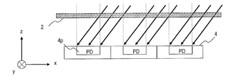
- FIG. 1A is a plan view schematically showing a part of a subject.
- the subject 2 shown in FIG. 1A is, for example, a thin piece of biological tissue (typically having a thickness of several tens of ⁇ m or less).
- the subject 2 is arranged close to the imaging surface of the image sensor.
- the distance from the imaging surface of the image sensor to the subject 2 is typically 1 mm or less, and can be set to about 1 ⁇ m, for example.
- FIG. 1B is a plan view schematically showing extracted photodiodes related to imaging of the region shown in FIG. 1A out of the photodiodes of the image sensor.
- FIG. 1B shows arrows indicating the x, y, and z directions orthogonal to each other.
- the z direction indicates the normal direction of the imaging surface.
- an arrow indicating the u direction that is a direction rotated by 45 ° from the x axis toward the y axis in the xy plane is also illustrated.
- an arrow indicating the x direction, the y direction, the z direction, or the u direction may be illustrated.
- Components other than the photodiode 4p in the image sensor 4 are covered with a light shielding layer.
- the hatched area indicates an area covered with the light shielding layer.
- the area (S2) of the light receiving surface of one photodiode on the imaging surface of the CCD image sensor is smaller than the area (S1) of the unit region including the photodiode.
- the ratio (S2 / S1) of the light receiving area S2 to the pixel area S1 is called "aperture ratio".
- aperture ratio is 25%.
- 2A and 2B schematically show the directions of light rays that pass through the subject 2 and enter the photodiode 4p.
- 2A and 2B show a state in which light rays are incident from a direction perpendicular to the imaging surface.
- no lens for image formation is disposed between the subject 2 and the image sensor 4, and the image of the subject 2 passes through the subject 2. Acquired using substantially parallel rays.
- FIG. 2C schematically shows an image Sa (first sub-image Sa) acquired under the irradiation direction shown in FIGS. 2A and 2B.
- the first sub-image Sa is composed of six pixels Pa acquired by six photodiodes 4p.
- Each pixel Pa has a value (pixel value) indicating the amount of light incident on the individual photodiode 4p.
- the first sub-image Sa has information on areas A1, A2, A3, A4, A5, and A6 (see FIG. 1A) in the entire subject 2. Note that light that has passed through a region not directly above the photodiode 4p does not enter the photodiode 4p. Therefore, in the first sub-image Sa, information on regions other than the regions A1, A2, A3, A4, A5, and A6 in the entire subject 2 is missing.
- FIGS. 3A and 3B show a state in which light rays are incident from an irradiation direction different from the irradiation direction shown in FIGS. 2A and 2B.
- the light rays shown in FIGS. 3A and 3B are inclined in the x direction with respect to the z direction. At this time, light that has passed through a region different from the region located immediately above the photodiode 4p in the entire subject 2 enters the photodiode 4p.
- FIG. 3C schematically shows an image Sb (second sub-image Sb) acquired under the irradiation direction shown in FIGS. 3A and 3B.
- the second sub-image Sb is also composed of six pixels acquired by the six photodiodes 4p.
- the pixels Pb constituting the second sub-image Sb are areas B1, B2, B3, B4, B5, and B6 (outside the areas A1, A2, A3, A4, A5, and A6 of the entire subject 2 (See FIG. 1A).
- the second sub-image Sb does not have information on the areas A1, A2, A3, A4, A5, and A6 in the entire subject 2, and instead, the areas B1, B2, B3, B4 , B5 and B6.
- the region B1 is a region adjacent to the right side of the region A1 in the subject 2 (see FIG. 1A).
- the light beam transmitted through different regions of the subject 2 is made incident on the photodiode 4p by appropriately changing the irradiation direction. be able to.
- the first sub image Sa and the second sub image Sb can include pixel information corresponding to different positions in the subject 2.
- FIG. 5A shows a state in which light rays are incident from an irradiation direction shown in FIGS. 2A and 2B, an irradiation direction shown in FIGS. 3A and 3B, and an irradiation direction different from the irradiation directions shown in FIGS. 4A and 4B.
- the light beam shown in FIG. 5A is inclined in a direction that forms an angle of 45 ° with the x axis in the xy plane with respect to the z direction.
- FIG. 6 shows a high-resolution image HR synthesized from four sub-images Sa, Sb, Sc, and Sd.
- the number of pixels or the pixel density of the high-resolution image HR is four times the number of pixels or the pixel density of each of the four sub-images Sa, Sb, Sc, and Sd.
- the pixel Pa1 of the sub-image Sa illustrated in FIG. 6 has information on only the area A1, not the entire block described above. Therefore, it can be said that the sub-image Sa is an image in which information on the areas B1, C1, and D1 is missing.
- the information missing in the sub-image Sa is complemented as shown in FIG. It is possible to form a high resolution image HR.
- a resolution four times the intrinsic resolution of the image sensor 4 is obtained.
- the degree of high resolution (super-resolution) depends on the aperture ratio of the image sensor. In this example, since the aperture ratio of the image sensor 4 is 25%, the resolution can be increased up to four times by irradiating light from four different directions.
- N is an integer greater than or equal to 2 if the aperture ratio of the image sensor 4 is approximately equal to 1 / N, the resolution can be increased up to N times.
- the sub-images Sa, Sb, Sc, and Sd shown in FIG. 6 have pixel information of different areas in the subject 2 and do not overlap. However, there may be overlap between different sub-images.
- the light beams that have passed through two adjacent regions in the subject 2 are both incident on the same photodiode.
- the setting of the irradiation direction is not limited to this example. For example, as shown in FIG. 7, the irradiation direction may be adjusted so that light beams that have passed through two adjacent regions of the subject 2 enter different photodiodes.
- ⁇ Module> In the formation of a high-resolution image based on the principle described with reference to FIGS. 1A to 6, acquisition of a sub image is executed in a state where the subject 2 is arranged close to the imaging surface of the image sensor 4.
- a sub image is acquired using a module having a structure in which the subject 2 and the image sensor 4 are integrated.
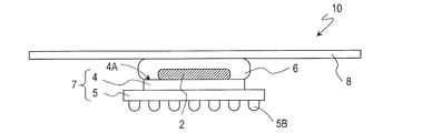
- FIG. 8A schematically shows an example of a cross-sectional structure of the module.
- the subject 2 covered with the encapsulant 6 is disposed on the imaging surface 4 ⁇ / b> A of the image sensor 4.
- a transparent plate (typically a glass plate) 8 is arranged on the subject 2. That is, in the configuration illustrated in FIG. 8A, the subject 2 is sandwiched between the image sensor 4 and the transparent plate 8. It is advantageous that the module 10 has the transparent plate 8 because workability is improved.
- the transparent plate 8 for example, a general slide glass can be used. Note that each element is schematically shown in the drawing, and the actual size and shape of each element do not necessarily match the size and shape shown in the figure. The same applies to other drawings referred to below.
- FIG. 8A shows an example of the appearance when the module 10 shown in FIG. 8A is viewed from the image sensor 4 side.
- the package 5 has a back electrode 5 ⁇ / b> B on the surface opposite to the transparent plate 8.
- the back electrode 5B is electrically connected to the image sensor 4 through a wiring pattern (not shown) formed on the package 5. That is, the output of the image sensor 4 can be taken out via the back electrode 5B.
- an imaging device a structure in which a package and an image sensor are integrated is referred to as an “imaging device”.
- a thin slice (tissue slice) of a biological tissue is illustrated as the subject 2.
- the module 10 having a biological tissue slice as the subject 2 can be used for pathological diagnosis.
- the tissue section A02 is placed on the transparent plate 8.
- the transparent plate 8 can be a slide glass used for observing a sample with an optical microscope. Below, a slide glass is illustrated as the transparent plate 8.
- the tissue section A02 is stained by immersing the tissue section A02 together with the transparent plate 8 in the staining solution Ss.
- the subject 2 obtained by staining the tissue section A02 is covered with the encapsulant 6 by applying the encapsulant 6 on the transparent plate 8.
- the encapsulant 6 has a function of protecting the subject 2.
- the image sensor 7 is disposed on the subject 2 such that the imaging surface of the image sensor 4 faces the subject 2. In this way, the module 10 is obtained.
- the module 10 is produced for each imaging target. For example, in a pathological diagnosis scene, a plurality of (for example, 5 to 20) tissue sections are prepared from one specimen. Therefore, a plurality of modules 10 having tissue sections obtained from the same specimen as the subject 2 can be produced. If a plurality of sub-images are acquired for each of the plurality of modules 10, a high-resolution image corresponding to each of the plurality of modules 10 can be formed.
- the module 10 includes an image sensor 4 that acquires an image of the subject 2, unlike a preparation used for observation with an optical microscope. Such a module may be called an “electronic preparation”.
- the use of the module 10 having a structure in which the subject 2 and the image sensor 7 are integrated has an advantage that the arrangement between the subject 2 and the image sensor 4 can be fixed.
- the subject 2 When acquiring an image of the subject 2 using the module 10, the subject 2 is irradiated with illumination light through the transparent plate 8. Illumination light transmitted through the subject 2 enters the image sensor 4. Thereby, an image of the subject 2 is obtained.
- a plurality of different images can be acquired at different angles during irradiation.
- the light source 310 is disposed immediately above the image sensor 4. Then, when imaging is performed in a state where the subject 2 is irradiated with the collimated light CL from the normal direction of the imaging surface 4A of the image sensor 4, a sub-image similar to the sub-image Sa illustrated in FIG. 2C is obtained. Further, as shown in FIG.
- FIG. 11A schematically shows an example of the relationship between the arrangement of the subject 2 and the irradiation direction.
- the two irradiation directions of the irradiation direction indicated by the dashed arrow DRa and the irradiation direction indicated by the solid arrow DRb are shown together.
- the illumination light irradiation from the direction indicated by the arrow DRa and the illumination light irradiation from the direction indicated by the arrow DRb are simultaneously performed. Are not executed, they are executed sequentially.
- the image sensor 4 has a transparent layer 4T that covers the light incident surface of the photodiode 4p.
- the subject 2 is located on the transparent layer 4T while being covered with the encapsulant 6.
- an interval between the imaging surface 4A and the subject 2 is schematically indicated by an arrow d1.
- FIG. 11B schematically shows a relationship between the illumination light transmitted through the subject 2 and the photodiode 4p in a module in which the subject 2 is arranged at a position farther from the imaging surface 4A of the image sensor 4.
- the interval d2 between the imaging surface 4A and the subject 2 is larger than the interval d1 in the example shown in FIG. 11A.
- the interval between the imaging surface 4A and the subject 2 may vary among a plurality of modules. Such a variation is considered to be caused, for example, by the inclusion of the encapsulant 6 (see FIG. 9) between the imaging surface 4A and the subject 2 when the module is manufactured.
- the distance between the imaging surface 4A and the subject 2 can have a variation in the range of about 2 to 8 ⁇ m.
- the light transmitted through the region B1 is not incident on any photodiode 4p of the image sensor 4.
- a sub-image having information on the area B1 in the subject 2 cannot be acquired.
- a sub-image for forming a high-resolution image cannot be obtained by irradiation from the irradiation direction indicated by the arrow DRb. Therefore, a high resolution image cannot be formed.
- FIG. 11C schematically shows another example of the relationship between the arrangement of the subject 2 and the irradiation direction.
- the interval d3 between the imaging surface 4A and the subject 2 is larger than the interval d1 in the example shown in FIG. 11A and smaller than the interval d2 in the example shown in FIG. 11B.
- the subject 2 is irradiated from the irradiation direction indicated by the arrow DRb, the light transmitted through a part of the region B1 and the light transmitted through a region different from the region B1 are incident on the photodiode 4p. To do. In the sub-image obtained at this time, a part of the information on the area B1 is missing.
- a plurality of irradiation directions set for a certain module are not necessarily appropriate as irradiation directions for acquiring a plurality of sub-images in other modules.
- a plurality of irradiation directions set for a certain module are directly applied to acquisition of a plurality of sub-images in another module, an appropriate high resolution image is obtained from the plurality of sub-images acquired according to the plurality of irradiation directions.
- the present inventor has repeatedly studied in view of the above, and has found an image acquisition device (digitizer), an image forming system, and an image forming method capable of improving the practicality of a high resolution technology that realizes a resolution exceeding the intrinsic resolution of an image sensor. It was.
- An image acquisition apparatus that is one aspect of the present disclosure includes an illumination system and an irradiation direction determination unit.
- the illumination system sequentially irradiates a subject from a plurality of different irradiation directions with respect to the subject on a module in which the subject and the image sensor are integrated so that illumination light transmitted through the subject enters the image sensor.
- This module is configured to acquire a plurality of images corresponding to a plurality of different irradiation directions with the subject as a reference by the imaging element.
- the irradiation direction determination unit determines a plurality of different irradiation directions based on a difference between the first preliminary image and the second preliminary image before acquiring a plurality of images by the imaging device according to a plurality of different irradiation directions. To decide.
- the first preliminary image is an image acquired by the imaging device when the subject is irradiated with the first illumination light from the first irradiation direction.
- the second preliminary image is an image acquired by the imaging device when the subject is irradiated with the second illumination light from the second irradiation direction.
- the irradiation direction determination unit includes a plurality of irradiation directions based on the first irradiation direction and the second irradiation direction selected so that the difference between the first preliminary image and the second preliminary image is smaller than a predetermined level. Determine different irradiation directions.
- the illumination system changes at least one of the first irradiation direction and the second irradiation direction.
- the imaging device acquires one or more first preliminary images and one or more second preliminary images according to a change in at least one of the first irradiation direction and the second irradiation direction.
- the irradiation direction determining unit is configured such that a difference between the first preliminary image and the second preliminary image is smaller than a predetermined level from one or more different image sets each including a first preliminary image and a second preliminary image.
- An image set is determined, and a plurality of different irradiation directions are determined based on the first irradiation direction and the second irradiation direction corresponding to the image set.
- the illumination system changes at least one of the first irradiation direction and the second irradiation direction.
- the imaging device acquires one or more first preliminary images and one or more second preliminary images according to a change in at least one of the first irradiation direction and the second irradiation direction.
- the irradiation direction determination unit minimizes a difference between the first preliminary image and the second preliminary image from a preset number of different image sets, each including a first preliminary image and a second preliminary image. Are determined, and a plurality of different irradiation directions are determined based on the first irradiation direction and the second irradiation direction corresponding to the image set.
- the first irradiation direction and the second irradiation direction are symmetrical with respect to the subject.
- the difference is an amount defined by the luminance of the pixel in the first preliminary image and the luminance of the pixel in the second preliminary image.
- the irradiation direction determination unit compares the luminance of the plurality of pixels constituting the first preliminary image with the luminance of the plurality of pixels constituting the second preliminary image, thereby obtaining the second preliminary image and the second preliminary image. The difference between the preliminary image and the preliminary image is calculated.
- the irradiation direction determination unit calculates a difference between the first preliminary image and the second preliminary image after correcting the luminance of the pixel in at least one of the first preliminary image and the second preliminary image.
- the irradiation direction determination unit acquires position information indicating the height of the subject with respect to the image sensor, and determines a plurality of different irradiation directions according to the position information.
- the illumination system includes a stage configured to be detachably loaded with a module, and a stage driving mechanism configured to change the attitude of the stage.
- An image forming system is configured to combine each of a plurality of images by combining the image acquisition device according to any one of the above and a plurality of images acquired according to a plurality of different irradiation directions. And an image processing apparatus that forms a high-resolution image of a subject with higher resolution.
- An image forming method includes a step of acquiring a first preliminary image of a subject, a step of acquiring a second preliminary image of the subject, and a plurality of different irradiation directions based on the subject.
- the step of acquiring the first preliminary image by irradiating the module in which the subject and the image sensor are integrated with the first illumination light from the first irradiation direction so that the illumination light transmitted through the subject enters the image sensor.
- a first preliminary image is acquired.
- the second preliminary image is acquired by irradiating the module with the second illumination light from the second irradiation direction.
- a plurality of different irradiation directions are determined based on the difference between the first preliminary image and the second preliminary image.
- a plurality of images corresponding to a plurality of different irradiation directions are acquired by sequentially irradiating the subject with illumination light from the plurality of different irradiation directions. .
- a high-resolution image of the subject having a higher resolution than each of the plurality of images is formed by combining the plurality of images.
- the step of acquiring the first preliminary image is executed a plurality of times while changing the first irradiation direction.
- the step of acquiring the second preliminary image is executed a plurality of times while changing the second irradiation direction.
- the first irradiation direction and the second irradiation direction are symmetrical with respect to the subject.
- the step of determining a plurality of different irradiation directions based on the first irradiation direction and the second irradiation direction such that a difference between the first preliminary image and the second preliminary image is smaller than a predetermined level.
- a plurality of different irradiation directions are determined.
- a plurality of the irradiation directions are determined based on the first irradiation direction and the second irradiation direction that minimize a difference between the first preliminary image and the second preliminary image.
- Different illumination directions are determined.
- the difference is an amount defined by the luminance of the pixel in the first preliminary image and the luminance of the pixel in the second preliminary image.
- the step of determining a plurality of different irradiation directions includes a step of comparing the luminances of the plurality of pixels constituting the first preliminary image with the luminances of the plurality of pixels constituting the second preliminary image.
- the image forming method includes a step of correcting the luminance of the pixels in the second preliminary image between the step of obtaining the second preliminary image and the step of determining a plurality of different irradiation directions.
- FIG. 12 illustrates an outline of an example of a configuration of an image acquisition device according to an embodiment of the present disclosure.
- the illumination system 30 is configured such that the light source 31 that generates the illumination light, the stage 32 configured to be detachably loaded with the module 10, and the posture of the stage 32 can be changed.
- the stage drive mechanism 33 is included.
- FIG. 12 schematically shows a state where the module 10 is loaded on the stage 32. However, illustration of the encapsulant 6 and the transparent plate 8 in the module 10 is omitted.
- the module 10 is not an essential component for the image acquisition apparatus 100a.
- the module 10 has an arrangement in which the illumination light transmitted through the subject 2 is incident on the image sensor 7 while being connected to the stage 32.
- the illumination system 30 changes the irradiation direction with the subject 2 as a reference, for example, by changing the posture of the stage 32.
- the change in “attitude” in the present specification broadly includes a change in inclination with respect to a reference plane, a change in rotation angle with respect to a reference orientation, a change in position with respect to a reference point, and the like.
- the subject 2 is irradiated with illumination light generated by the light source 31 sequentially from a plurality of different irradiation directions with the subject 2 as a reference. Details of the configuration and operation of the illumination system 30 will be described later.
- a plurality of different images (sub-images) according to a plurality of different irradiation directions are acquired by the image sensor 7.
- a high-resolution image can be formed using the obtained plurality of images.
- the irradiation direction determination unit 40a determines a plurality of different irradiation directions when a plurality of sub-images are acquired by the image sensor 7.
- the acquisition of the sub-image is executed under a plurality of different irradiation directions determined by the irradiation direction determination unit.
- the sub-images in the embodiment of the present disclosure are a plurality of different images corresponding to a plurality of different irradiation directions determined by the irradiation direction determination unit.
- the irradiation direction determination unit 40a determines a plurality of different irradiation directions when acquiring a plurality of sub-images based on the difference between the first preliminary image and the second preliminary image. A specific example of the configuration and operation of the irradiation direction determination unit 40a will be described later.
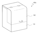
- the image acquisition device 100a includes a main body 110 including a light source 31 and a stage 32, and a lid 120 that is connected to the main body 110 so as to be openable and closable. By closing the lid 120, a dark room can be formed inside the image acquisition device 100a (see FIG. 13B).
- a socket 130 for holding the module 10 is connected on the stage 32.
- the socket 130 may be fixed to the stage 32, or may be configured to be detachable from the stage 32.
- a configuration in which the socket 130 is configured to be detachable from the stage 32 is illustrated.
- the socket 130 includes, for example, a lower base material 132 in which the module 10 is detachable and an upper base material 134 in which the opening Ap is formed.
- the socket 130 holds the module 10 by sandwiching the module 10 between the lower base material 132 and the upper base material 134.
- the lower base member 132 may have an electrical connection portion having an electrical contact for electrical connection with the image sensor 7 of the module 10.
- the module 10 is placed on the lower base material 132 so that the imaging surface of the imaging device 7 faces the light source 31.
- the electrical contact of the electrical connection portion and the back electrode 5B (see FIGS. 8A and 8B) of the imaging device 7 come into contact with each other, so that the imaging device 7 of the module 10 and the electrical connection portion of the lower substrate 132 are connected. Electrically connected.
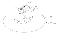
- FIG. 13C shows an example of a method for loading the socket 130 into the stage 32 of the image acquisition apparatus 100a.
- the socket 130 includes an electrode 136 that protrudes from the bottom surface. This electrode 136 may be part of the electrical connection of the lower substrate 132.
- the stage 32 of the image acquisition device 100a has a mounting portion 34 provided with a jack 36.
- the socket 130 holding the module 10 is loaded on the stage 32 so that the electrode 136 of the socket 130 is inserted into the jack 36. Thereby, the electrical connection between the image sensor 7 in the module 10 held in the socket 130 and the image acquisition device 100a is established.
- the stage 32 may have a circuit that receives the output of the image sensor 4 in a state in which the socket 130 that holds the module 10 is loaded.
- the image acquisition device 100a acquires information (image signal or image data) indicating an image of the subject 2 with the electrical connection unit included in the socket 130 as an intermediary.
- the same number of sockets 130 as the modules 10 are prepared, and the imaging target is changed by replacing the sockets 130 holding the modules 10. Also good.
- the imaging target may be changed by replacing the module 10 with the single socket 130 attached to the stage 32.
- the bottom surface of the socket 130 and the top surface of the attachment portion 34 can be brought into close contact with each other.
- the arrangement of the socket 130 with respect to the stage 32 is fixed. Therefore, the arrangement of the stage 32 and the module 10 held in the socket 130 can be kept constant before and after the change in the posture of the stage 32.
- the main surface of the transparent plate 8 of the module 10 and the stage 32 are substantially parallel.
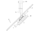
- FIG. 14A shows an example of a method of changing the irradiation direction.
- the illumination light CL emitted from the light source 31 is irradiated to the module 10 held in the socket 130.
- the illumination light CL is incident on the subject of the module 10 through the opening Ap provided in the socket 130.
- the light transmitted through the subject enters the imaging surface of the imaging device 7 of the module 10.
- the light emitted from the light source 31 is typically collimated light. However, when the light incident on the subject can be regarded as substantially parallel light, the light emitted from the light source 31 may not be collimated light.
- the light source 31 includes, for example, an LED chip.
- the light source 31 may include a plurality of LED chips each having a peak in a different wavelength band.
- the light source 31 may include an LED chip that emits blue light, an LED chip that emits red light, and an LED chip that emits green light.
- a plurality of light emitting elements are arranged close to each other (for example, about 100 ⁇ m), these can be regarded as point light sources.
- a plurality of sub-images for each color can be acquired.
- a set of blue sub-images, a set of red sub-images, and a set of green sub-images may be obtained.
- a high-resolution color image can be formed using the acquired set of sub-images. For example, in a pathological diagnosis scene, more useful information regarding the presence or absence of a lesion can be obtained by using a color high-resolution image.
- illumination lights of different colors may be obtained in a time sequential manner.
- an image sensor for color imaging may be used as the image sensor 4.
- a configuration without a color filter is more advantageous.
- the light source 31 is not limited to an LED, and may be an incandescent bulb, a laser element, a fiber laser, a discharge tube, or the like.
- the light emitted from the light source 31 is not limited to visible light, and may be ultraviolet light, infrared light, or the like.
- the number and arrangement of the light emitting elements included in the light source 31 can be arbitrarily set.
- the image acquisition apparatus 100a has a stage drive mechanism 33.
- the stage drive mechanism 33 includes a gonio mechanism, a rotation mechanism, and the like, and changes the tilt angle of the stage 32 with respect to the main body 110 and / or a rotation angle with respect to an axis passing through the center of the stage 32.
- the stage drive mechanism 33 may include a slide mechanism that can translate the stage 32 in a reference plane (typically a horizontal plane).
- the posture of the stage 32 can be changed by operating the stage drive mechanism 33.
- the posture of the module 10 can be changed by changing the posture of the stage 32.
- the incident direction of the illumination light when the stage 32 is not inclined with respect to the reference plane is the normal direction of the imaging surface of the image sensor.
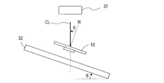
- the relationship (for example, parallel) between the inclination of the stage 32 with respect to the reference plane and the inclination of the module 10 with respect to the reference plane (which may be referred to as the inclination of the transparent plate 8) is the change in the attitude of the stage 32. It is kept constant before and after. Therefore, as shown in FIG.
- a broken line N indicates a normal line of the imaging surface of the image sensor.
- the irradiation direction with respect to the subject 2 is, for example, an angle (normal angle ⁇ shown in FIG. 14B) formed by the normal N of the imaging surface of the image sensor and the incident light to the subject 2, and a reference set on the imaging surface. It can be expressed by a set of angles (azimuth angles) formed by the azimuth and the projection of incident light onto the imaging surface.
- the irradiation direction may be changed by moving the light source 31 along the direction connecting the light source 31 and the subject 2.
- the irradiation direction may be changed by combining the change in the posture of the stage 32 and the movement of the light source 31.
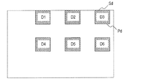
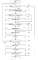
- FIG. 15 shows an outline of an exemplary image forming method according to an embodiment of the present disclosure.
- the image forming method illustrated in FIG. 15 generally includes a step of acquiring a first preliminary image (S2), a step of acquiring a second preliminary image (S4), a first preliminary image, and a second preliminary image.
- the module in which the subject and the image sensor are integrated is an image of a subject acquired by irradiation from two irradiation directions.
- the acquisition of the first preliminary image can be executed a plurality of times while changing the first irradiation direction.
- the acquisition of the second preliminary image can also be executed a plurality of times by changing the second irradiation direction.
- the first irradiation direction is not limited to a single direction, and may include a plurality of directions. Therefore, the number of first preliminary images is not limited to one.
- the second irradiation direction is not limited to a single direction and may include a plurality of directions.
- the number of second preliminary images is not limited to one.
- the order of obtaining the first preliminary image and the second preliminary image is not limited to the order illustrated in FIG.
- the “difference” between the first preliminary image and the second preliminary image is an image set composed of a certain first preliminary image and a single second preliminary image. Includes a wide range of values indicating the similarity between two images calculated from the first preliminary image and the second preliminary image.
- an image block including a plurality of pixels for each of the first preliminary image and the second preliminary image constituting an image set.
- a “difference” between the first preliminary image and the second preliminary image a sum of absolute values of differences in luminance of pixels between them (Sum of Absolute Difference) or a sum of squares of differences in luminance of pixels (Sum of) Squared difference may be used.
- Normalized Cross-Correlation, Zero-means used for template matching Normalized Cross-Correlation etc. are also “difference” between the first preliminary image and the second preliminary image. Is available as
- the plurality of irradiation directions determined based on the difference between the first preliminary image and the second preliminary image may be irradiation directions according to the height of the subject with respect to the image sensor.
- the height of the subject relative to the image sensor means the distance from the center to the imaging surface in the thickness direction of the subject. In the embodiment of the present disclosure, it is sufficient if an approximate guide for the height of the subject with respect to the image sensor can be determined based on the difference between the first preliminary image and the second preliminary image.
- the arrangement of the imaging elements at the time of acquiring the subject image is not limited to an arrangement in which the imaging surface is horizontal. Therefore, “height” in the present specification means a length measured along the normal direction of the imaging surface of the image sensor, and is not limited to the length measured along the vertical direction.
- a plurality of images are combined to form a high-resolution image of a subject having a higher resolution than each of the plurality of images.
- the principle described with reference to FIGS. 1A to 6 can be applied to the formation of a high resolution image. According to the embodiment of the present disclosure, it is possible to reliably acquire a sub-image that can be used to form a high-resolution image. Note that the above-described steps do not have to be executed continuously.
- preliminary imaging is performed prior to acquisition of a plurality of sub-images.
- first preliminary images and one or more second preliminary images are acquired.
- the first preliminary image is an image acquired by the imaging device when illuminated with illumination light from the first illumination direction.
- the second preliminary image is an image acquired by the imaging device when illuminated with illumination light from the second illumination direction.
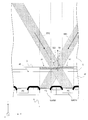
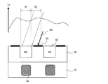
- FIG. 16A schematically shows an example of the relationship between the illumination light irradiation direction and the area of the subject 2 through which the illumination light is transmitted.
- the two irradiation directions of the first irradiation direction indicated by the solid line arrow DR1 and the second irradiation direction indicated by the solid line arrow DR2 are shown together. Note that this is only for convenience of explanation, and irradiation from the first irradiation direction and irradiation from the second irradiation direction are not performed simultaneously. In other drawings, a plurality of irradiation directions may be shown in one drawing.
- the area A1 of the subject 2 is located immediately above the photodiode 4pa, and the area A2 of the subject 2 is located immediately above the photodiode 4pb adjacent to the photodiode 4pa.
- attention is paid to a region B1 in the subject 2 between the region A1 and the region A2.
- the light transmitted through the region B1 of the subject 2 is incident on the photodiode 4pa. That is, among the luminances (pixel values) of a plurality of pixels included in the first preliminary image acquired under irradiation from the first irradiation direction DR1, the luminance of the pixel corresponding to the photodiode 4pa is that of the subject 2.
- the amount of light transmitted through the region B1 is shown.
- the luminance of the pixel corresponding to the photodiode 4pb among the luminances of the plurality of pixels included in the second preliminary image acquired under the irradiation from the second irradiation direction DR2 is the photodiode 4pa.
- the brightness of the corresponding pixel is different.
- the second preliminary image is acquired again by changing the second irradiation direction (see FIG. 16B).
- the irradiation angle ⁇ 22 shown in FIG. 16B is smaller than the irradiation angle ⁇ 21 shown in FIG. 16A.
- the luminance of the pixel corresponding to the photodiode 4pb is the same as the luminance of the plurality of pixels included in the first preliminary image.
- the luminance of the pixel corresponding to the diode 4pa is almost the same. That is, light that has passed through a certain region of the subject 2 under irradiation from the first irradiation direction is incident on a certain photodiode (photodiode 4pa in this case) and is also irradiated from the second irradiation direction.
- a certain photodiode photodiode 4pa in this case
- the difference between the pixel values obtained by these photodiodes is minimized. .
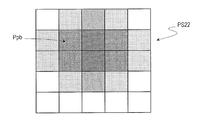
- 16C and 16D show the first preliminary image PS1 acquired under the irradiation from the first irradiation direction DR1 shown in FIG. 16B and the irradiation from the second irradiation direction DR2 shown in FIG. 16B, respectively.
- the acquired 2nd preliminary image PS2 is shown typically.
- a pixel Ppa in FIG. 16C and a pixel Ppb in FIG. 16D indicate pixels corresponding to the photodiode 4pa and the photodiode 4pb, respectively.
- the luminance of the pixel Ppa corresponding to the photodiode 4pa and the luminance of the pixel Ppb corresponding to the photodiode 4pb are substantially the same.
- the positions of the pixel Ppa and the pixel Ppb having information on the region B1 are shifted by one pixel between the first preliminary image PS1 and the second preliminary image PS2.
- the luminance distribution of the first preliminary image PS1 and the luminance distribution of the image obtained by shifting the second preliminary image PS2 by one pixel along the horizontal direction in the figure are: Almost matches.
- “luminance distribution” means a spatial arrangement of pixel values indicating the brightness of each pixel.
- FIG. 16E schematically shows a second preliminary image PS22 acquired under irradiation from the second irradiation direction DR2 shown in FIG. 16A.
- a pixel Ppb in FIG. 16E indicates a pixel corresponding to the photodiode 4pb.
- FIG. 16E and FIG. 16C light incident on the photodiode 4pa under irradiation from the first irradiation direction and incident on the photodiode 4pb under irradiation from the second irradiation direction.
- the luminance of the pixel Ppa corresponding to the photodiode 4pa and the luminance of the pixel Ppb corresponding to the photodiode 4pb are not substantially the same. .
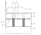
- FIG. 17A schematically shows another example of the relationship between the illumination light irradiation direction and the region of the subject 2 through which the illumination light is transmitted.
- 17A shows a first irradiation direction DR1 shown in FIG. 16B and a first irradiation direction shown in FIG. 16B using a module in which the subject 2 is located farther from the imaging surface 4A of the image sensor 4 than the examples shown in FIGS. 16A and 16B.
- a case is shown in which irradiation is performed from two irradiation directions DR2.
- the photodiode 4pa when irradiated from the first irradiation direction DR1, light that has passed through a region different from the region B1 of the subject 2 is incident on the photodiode 4pa. Further, when irradiated from the second irradiation direction DR2, the photodiode 4pb adjacent to the photodiode 4pa is different from the region through which the illumination light from the first irradiation direction DR1 of the subject 2 passes, and the region of the subject 2 Light transmitted through a region different from B1 is incident.
- the luminance of the pixel corresponding to the photodiode 4pa is different from the luminance of the pixel corresponding to the photodiode 4pb.
- the combination of the first irradiation direction and the second irradiation direction that minimizes the difference between the pixel values obtained by two adjacent photodiodes can be different for each module.
- FIG. 17B shows a first irradiation direction DR1 and a second irradiation direction DR2 in which light transmitted through the region B1 of the subject 2 shown in FIG. 17A is incident on the photodiode 4pa and the photodiode 4pb, respectively.
- the irradiation angle ⁇ 23 shown in FIG. 17B is smaller than the irradiation angle ⁇ 22 shown in FIG. 17A.
- the illumination light from the first irradiation direction and the illumination light from the second irradiation direction are the same in the subject 2 (
- the light can enter the region B1).
- the light transmitted through the same region in the subject 2 can be incident on the photodiodes adjacent to each other (here, the photodiode 4pa and the photodiode 4pb). At this time, the difference between the pixel values obtained by the photodiodes adjacent to each other is minimal.
- the first irradiation direction and the second preliminary image are captured while changing the irradiation direction, and the first irradiation direction in which the difference between the pixel values obtained by adjacent photodiodes is minimized.
- the relative approximate arrangement between the region through which the light beam passes and the photodiode through which the transmitted light beam enters in the subject 2 is acquired. It is possible to know before. If the relative approximate arrangement between the region through which light passes through the subject 2 and the photodiode through which transmitted light enters is known, a plurality of irradiation directions suitable for acquisition of a plurality of sub-images, for example, geometrically calculated. Is possible.
- a plurality of irradiation directions suitable for acquiring a plurality of sub-images before acquiring the plurality of sub-images. Further, if the above-described method is applied for each module, a plurality of irradiation directions suitable for acquiring a plurality of sub-images even when there is a variation in the height of the subject with respect to the image sensor between the plurality of modules. Can be calculated for each module. Thereby, more reliable formation of a high resolution image can be realized.
- the combination of the first irradiation direction and the second irradiation direction that minimizes the difference between the pixel values obtained by the adjacent photodiodes can vary depending on the height of the subject relative to the element.
- Position information indicating the interval or position information indicating the height of the subject with respect to the image sensor can also be obtained. Using such position information, an appropriate irradiation direction according to the height of the subject may be determined for each module.
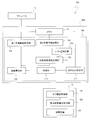
- FIG. 18 shows an example of an image forming system according to an embodiment of the present disclosure.
- An image forming system 500 illustrated in FIG. 18 includes an image acquisition device 100a and an image processing device 150.
- illustration of the illumination system 30 is omitted.
- the image processing apparatus 150 can be realized by a general-purpose or dedicated computer (or a general-purpose or dedicated processor).
- the image processing device 150 may be integrated with the image acquisition device 100a, or may be a separate device different from the image acquisition device 100a.
- the image processing apparatus 150 does not have to be disposed at the same place as the image acquisition apparatus 100a.
- the image processing apparatus 150 may be arranged at a location different from the image acquisition apparatus 100a and connected via a network such as the Internet.
- the image processing apparatus 150 includes a sub image acquisition unit 152 and a high resolution image forming unit 154.
- the sub-image data acquired by the image acquisition device 100 a is sent to the image processing device 150.
- the sub image acquisition unit 152 of the image processing apparatus 150 acquires sub image data.
- the high-resolution image forming unit 154 of the image processing apparatus 150 synthesizes a plurality of sub-images using the principle described with reference to FIGS. 1A to 6, and the high-resolution of the subject having a higher resolution than each of the sub-images. Form an image.
- the image processing apparatus 150 may have a function as a control apparatus that supplies various commands for controlling the operation of each unit of the image acquisition apparatus 100a.
- a configuration in which the image processing device 150 includes a control device 156 that supplies various commands for controlling the operation of each unit of the image acquisition device 100a will be described as an example.
- a system having a configuration in which the image processing device 150 and the control device 156 are separate devices is also possible.
- the control device 156 and the image processing device 150 may be connected via a network such as the Internet.
- the image processing device 150 installed at a location different from the control device 156 may receive sub-image data acquired by the image acquisition device 150a and execute high-resolution image formation.
- the image acquisition device 100 a includes an irradiation direction determination unit 40 a and a memory 50.
- the whole or a part of the irradiation direction determination unit 40a includes a digital signal processor (DSP), an ASIC (application specific integrated circuit), an ASSP (Application Specific Standard Produce), an FPGA (Field Programmable Gate Array), and a microcomputer. Or the like.
- the irradiation direction determination unit 40a includes a first preliminary image acquisition unit 102, a second preliminary image acquisition unit 104, a comparison target pixel value calculation unit 106a, a difference calculation unit 108, a determination unit 110, and an irradiation direction calculation unit. 112 is included. Each of these may be a separate processor, or two or more of these may be included in one processor.
- the memory 50 is a RAM.
- the memory 50 is not limited to the RAM, and a known storage device can be used.
- the irradiation direction determination unit 40a may have a memory 50 in a part thereof.
- the memory 50 stores, for example, information indicating the first irradiation direction DR1 and the second irradiation direction DR2 (see, for example, FIG. 16A). Table 1 below shows an example of information indicating the first irradiation direction DR1 and information indicating the second irradiation direction DR2.
- the value of the first irradiation angle indicating the first irradiation direction DR1 and the value of the second irradiation angle indicating the second irradiation direction DR2 are stored in the memory 50.
- the values of the first irradiation angle and the second irradiation angle shown in Table 1 correspond to the magnitude of the angle ⁇ shown in FIG. 14B, for example.
- the ID shown in the first column is an index for identifying a set of the first irradiation angle and the second irradiation angle.
- the number of sets of the first irradiation angle and the second irradiation angle, the value of the first irradiation angle, the value of the second irradiation angle, and the like can be arbitrarily set.
- the first irradiation angle value and the second irradiation angle value are set in 5 ° steps.
- the value of the second irradiation angle for the same ID is a value obtained by multiplying the value of the first irradiation angle by -1.
- FIG. 19 shows an example of the operation in the image forming system 500.
- step S12 the first irradiation angle value and the second irradiation corresponding to the IDs not yet selected in the list of the first and second irradiation angles stored in the memory 50. It is determined whether there is an angle value.
- the process proceeds to step S14.
- the first preliminary image acquisition unit 102 or the second preliminary image acquisition unit 104 determines whether or not there is a first irradiation angle value and a second irradiation angle value corresponding to an ID that has not yet been selected. Can be done.
- step S14 information indicating the first irradiation direction DR1 and information indicating the second irradiation direction DR2 are read from the memory 50 by the first preliminary image acquisition unit 102 and the second preliminary image acquisition unit 104, respectively.
- ⁇ 5 ° is read as the value of the first irradiation angle
- 5 ° is read as the value of the second irradiation angle.
- Table 1 in this example, the first irradiation direction DR1 and the second irradiation direction DR2 are symmetric with respect to the subject.
- step S ⁇ b> 16 the first preliminary image is acquired based on the control by the first preliminary image acquisition unit 102.
- the acquisition of the first preliminary image is executed in a state where the irradiation direction with respect to the subject is ⁇ 5 °.
- the subject is irradiated with illumination light.
- Information indicating the first preliminary image acquired at this time is temporarily stored in the memory 50.
- step S18 a second preliminary image is acquired based on control by the second preliminary image acquisition unit 104.
- the inclination of the stage 32 is changed so that the irradiation direction with respect to the subject becomes 5 °.
- imaging of the subject is executed.
- Information indicating the acquired second preliminary image is temporarily stored in the memory 50.
- step S20 the comparison target pixel value is acquired by the comparison target pixel value acquisition unit 106a.
- the first irradiation direction and the second irradiation are such that light transmitted through a region between two regions located immediately above two photodiodes adjacent to each other enters these photodiodes. Search for directions. Therefore, when comparing the luminance of the pixels in the first preliminary image and the luminance of the pixels in the second preliminary image, the luminance of the pixels at the same position in these preliminary images is not compared, but at a certain position. The luminance of a certain pixel is compared with the luminance of a pixel shifted by one pixel from the position (see FIGS. 16C and 16D).
- the comparison target pixel value acquisition unit 106a acquires the luminance of the pixel Ppb corresponding to the photodiode 4pb adjacent to the photodiode 4pa.
- the difference calculation unit 108 calculates the difference between the first preliminary image and the second preliminary image. For example, as a difference between the first preliminary image and the second preliminary image, an absolute value of a difference between the luminance of the pixel in the first preliminary image and the luminance of the pixel in the second preliminary image is calculated.
- the absolute value of the difference between the luminance of the pixel Ppa corresponding to the photodiode 4pa and the luminance of the pixel Ppb corresponding to the photodiode 4pb acquired by the comparison target pixel value acquisition unit 106a is calculated. An example will be described.
- two or more pixels may be selected from each of the first preliminary image and the second preliminary image, and the luminance of the pixels may be compared.
- the absolute value of the difference in luminance between pixels is calculated for each of a plurality of pixel groups each composed of one pixel in the first preliminary image and one pixel in the second preliminary image corresponding to the pixel. Then, the average value thereof may be used as the difference between the first preliminary image and the second preliminary image.
- step S24 the determination unit 110 determines whether or not the difference calculated in step S22 is greater than or equal to a predetermined level.
- the difference between the first preliminary image and the second preliminary image is smaller than a predetermined level set in advance, the light transmitted through the region B1 of the subject 2 under irradiation from the first irradiation direction It can be determined that light incident on the photodiode 4pa and transmitted through the region B1 of the subject 2 under irradiation from the second irradiation direction is incident on the photodiode 4pb.
- the region through which the light beam passes and the transmitted light beam in the subject 2 It is possible to know a relative approximate arrangement with respect to the incident photodiode.
- the level for determination can be set as appropriate.
- the level for determination may be determined using a module whose height of the subject with respect to the image sensor is known. If a module whose subject height is known with respect to the image sensor is used, light transmitted through the region B1 of the subject 2 under irradiation from the first irradiation direction and under irradiation from the second irradiation direction. It is possible to determine the magnitude of the difference between the first preliminary image and the second preliminary image when the light transmitted through the region B1 of the subject 2 enters each of the adjacent photodiodes. You may utilize the magnitude
- step S26 If it is determined that the difference between the first preliminary image and the second preliminary image is smaller than the predetermined level, the process proceeds to step S26. On the other hand, if it is determined that the difference between the first preliminary image and the second preliminary image is greater than or equal to a predetermined level, the process returns to step S12.
- step S12 When the process returns to step S12, the first irradiation angle value and the second irradiation angle value corresponding to the IDs not yet selected in the list of the first and second irradiation angles stored in the memory 50 are displayed. The determination of whether or not there is performed again.
- the process proceeds to step S14.
- step S14 information indicating the first irradiation direction DR1 and information indicating the second irradiation direction DR2 are read from the memory 50, respectively.
- the value of the first irradiation angle and the value of the second irradiation angle whose ID is 2 are read out.
- step S26 based on the first irradiation direction and the second irradiation direction such that the difference between the first preliminary image and the second preliminary image is smaller than a predetermined level, the irradiation direction calculation unit 112 performs sub-image conversion.
- a plurality of irradiation directions used for acquisition are calculated.
- Information indicating a plurality of calculated irradiation directions is stored in the memory 50 and used in a sub-image acquisition step described later.
- the plurality of irradiation directions can be calculated using position information indicating the height of the subject with respect to the image sensor, the arrangement pitch of the photodiodes, and the like. Thereby, a plurality of irradiation directions are determined.
- the state in which a plurality of irradiation directions are determined means a state in which, for example, information indicating a plurality of irradiation directions (for example, values of a plurality of irradiation angles) is held in a memory or the like, so that a plurality of irradiation directions can be specified.
- the plurality of irradiation directions used for acquiring the sub image are limited to the irradiation directions selected from the first irradiation direction used for acquiring the first preliminary image and the second irradiation direction used for acquiring the second preliminary image. Instead, it may be in a different direction.
- step S28 a plurality of sub-images corresponding to the plurality of irradiation directions calculated by the irradiation direction calculation unit 112 are acquired (see FIGS. 2A to 5B).
- step S3 At 0, a high-resolution image of the subject is formed using the plurality of sub-images acquired (see FIG. 6).
- the embodiment of the present disclosure it is possible to determine a plurality of irradiation directions suitable for acquisition of sub-images according to individual modules. By obtaining a sub-image under an appropriate irradiation direction corresponding to each module, it is possible to realize formation of an appropriate high-resolution image. Therefore, according to the embodiment of the present disclosure, the practicality of the high resolution technology that realizes a resolution exceeding the intrinsic resolution of the image sensor is improved.
- the first irradiation direction and the second irradiation direction are found such that the difference between the first preliminary image and the second preliminary image is smaller than a predetermined level
- the first irradiation direction and The search for the second irradiation direction is terminated.
- a plurality of sets of first and second irradiation directions are determined such that the difference between the first preliminary image and the second preliminary image is smaller than a predetermined level, and the plurality of first and second irradiations are determined.
- a plurality of different irradiation directions may be determined using the direction.
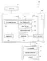
- FIG. 20 illustrates another example of an image forming system according to an embodiment of the present disclosure.
- the difference between the irradiation direction determination unit 40b and the irradiation direction determination unit 40a (see FIG. 18) of the image acquisition apparatus 100b shown in FIG. 20 is that the irradiation direction determination unit 40b replaces the comparison target pixel value calculation unit 106a.
- the brightness normalization unit 105b and the comparison target image generation unit 106b are provided.
- FIG. 21 shows another example of the operation in the image forming system 500.
- a comparison is made between the luminance distribution of the first preliminary image and the luminance distribution of the second preliminary image.
- a plurality of different irradiation directions used for acquiring the sub-image are determined. .
- the number of acquisitions of the first preliminary image is one.
- the acquisition of the second preliminary image is executed a plurality of times while changing the second irradiation direction. Therefore, here, the memory 50 stores information indicating the second irradiation direction DR2.
- Table 2 below shows the second irradiation direction D An example of information indicating R2 is shown.
- step S16 a first preliminary image is acquired.
- the acquisition of the first preliminary image is executed in a state where the irradiation direction with respect to the subject is 0 °.
- Information indicating the first preliminary image acquired at this time is temporarily stored in the memory 50.
- step S34 the second preliminary image acquisition unit 104 reads out information indicating the second irradiation direction DR2 from the memory 50.
- 5 ° is read as the value of the second irradiation angle.
- step S18 a second preliminary image is acquired.
- the acquisition of the second preliminary image is executed in a state where the irradiation direction with respect to the subject is 5 °.
- Information indicating the acquired second preliminary image is temporarily stored in the memory 50.
- luminance normalization means that the sum of the luminances of a plurality of pixels included in an image to be normalized is equal to the sum of the luminances of a plurality of pixels included in a reference image. Means a process of multiplying the luminance of each pixel by a constant.
- the first irradiation direction DR1 is parallel to the normal direction of the imaging surface of the image sensor
- the second irradiation direction DR2 is the imaging surface of the image sensor. It is inclined with respect to the normal direction. That is, the distance traveled until the light transmitted through the subject reaches the imaging surface is larger when the light is irradiated from the second irradiation direction DR2 than when the light is irradiated from the first irradiation direction DR1.
- the second preliminary image as a whole may be darker than the first preliminary image due to the influence of absorption, scattering, etc. in the module. If the difference between the overall brightness of the first preliminary image and the overall brightness of the second preliminary image is large, the difference between the first preliminary image and the second preliminary image is determined. It may not be possible to evaluate correctly.
- luminance normalization is performed on the second preliminary image.
- the luminance of each pixel in the second preliminary image can be corrected to an appropriate size. Therefore, a more accurate evaluation of the magnitude of the difference between the first preliminary image and the second preliminary image becomes possible.
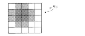
- step S38 the comparison target image generation unit 106b generates an image obtained by shifting the second preliminary image by a predetermined number of pixels (hereinafter, simply referred to as “shifted image”).
- shifted image an image obtained by shifting the second preliminary image after luminance normalization by one pixel is generated.
- FIG. 22 schematically illustrates an example of the first irradiation direction DR1 and the second irradiation direction DR2 in the second specific example.
- first irradiation direction DR1 when irradiated from the first irradiation direction DR1, light transmitted through the region A1 in the subject 2 immediately above the photodiode 4pa is incident on the photodiode 4pa.
- second irradiation direction DR2 when irradiated from the second irradiation direction DR2, the light transmitted through the region A1 in the subject 2 is incident on the photodiode 4pb adjacent to the photodiode 4pa.
- the first preliminary image similar to the first preliminary image PS1 shown in FIG. 16C and the first preliminary image shown in FIG. 16D.
- a second preliminary image similar to the two preliminary images PS2 is obtained.
- the second irradiation direction DR2 in which the light transmitted through the region other than the region A1 in the subject 2 is incident on the photodiode 4pb the same as the second preliminary image PS22 shown in FIG. 16E.
- a second preliminary image is obtained.
- FIG. 23A schematically shows a shift image PS32 generated from the second preliminary image acquired under irradiation from the second irradiation direction DR2 shown in FIG.
- FIG. 23B schematically shows a shift image PS42 generated from a second preliminary image acquired under irradiation from an irradiation direction different from the second irradiation direction DR2 shown in FIG.
- the luminance distribution of the first preliminary image and the luminance of the shift image generated from the second preliminary image is almost the same.
- the luminance distribution of the shift image generated from the second preliminary image acquired under the other second irradiation direction is the first preliminary image. It is different from the luminance distribution. Therefore, light that has passed through a certain area of the subject 2 under irradiation from the first irradiation direction enters a certain photodiode, and that area of the subject 2 under irradiation from the second irradiation direction.
- the transmitted light When the transmitted light is incident on the photodiode adjacent to the photodiode, it can be said that the difference between the first preliminary image and the second preliminary image is minimized. Therefore, as in the example described with reference to FIGS. 16A to 17B, the combination of the first irradiation direction and the second irradiation direction is such that the difference between the first preliminary image and the second preliminary image is minimized. As a result, it is possible to know the relative approximate arrangement between the region through which the light beam passes and the photodiode through which the transmitted light beam enters in the subject 2 before acquiring the sub-image.
- step S22 the difference between the first preliminary image and the second preliminary image is calculated.
- the absolute value of the difference between the luminance of the pixel in the first preliminary image and the luminance of the pixel in the shifted image generated from the second preliminary image is calculated for each pixel, and the sum of these absolute values is calculated as the first preliminary image.
- the second preliminary image the variance obtained by calculating the square of the difference between the luminance of the pixel in the first preliminary image and the luminance of the pixel in the shifted image generated from the second preliminary image for each pixel and adding them together is It may be a difference between the first preliminary image and the second preliminary image.
- step S24 it is determined whether or not the difference calculated in step S22 is greater than or equal to a predetermined level.
- the difference between the first preliminary image and the second preliminary image is smaller than a predetermined level, as described with reference to FIGS. 22 to 23B, the subject 2 is irradiated under the irradiation from the first irradiation direction.
- light transmitted through a certain region enters a certain photodiode, and light transmitted through that region of the subject 2 under irradiation from the second irradiation direction enters a photodiode adjacent to the photodiode. I can judge.
- step S26 If it is determined that the difference between the first preliminary image and the second preliminary image is smaller than the predetermined level, the process proceeds to step S26.
- the subsequent processing is the same as the processing described with reference to FIG.
- the process returns to step S32. Thereafter, the above-described steps S34 to S24 are repeated until a combination of the first irradiation direction and the second irradiation direction is found such that the difference between the first preliminary image and the second preliminary image becomes smaller than a predetermined level. .
- the first preliminary image is acquired once, and a comparison is made between one first preliminary image and second preliminary images acquired in accordance with a plurality of second irradiation directions. . Therefore, it is possible to shorten the processing time required to determine a plurality of irradiation directions as compared to a case where imaging is performed a plurality of times in both the first irradiation direction and the second irradiation direction.
- the first preliminary image may be acquired after acquiring a plurality of second preliminary images.
- the difference between the first preliminary image and the second preliminary image is calculated.
- the target to be subjected to luminance normalization can be appropriately set according to the settings of the first irradiation direction and the second irradiation direction.
- the luminance normalization may be performed on one or both of the first preliminary image and the second preliminary image.
- the luminance normalization may be performed between acquisition of the luminance normalization target and determination of a plurality of different irradiation directions.
- FIG. 24 illustrates still another example of an image forming system according to an embodiment of the present disclosure.
- the difference between the irradiation direction determination unit 40c and the irradiation direction determination unit 40b (see FIG. 20) included in the image acquisition device 100c illustrated in FIG. 24 is that the irradiation direction determination unit 40c does not include the luminance normalization unit 105b.
- it has a shift amount holding unit 107c connected to the comparison target image generation unit 106c.
- the shift amount holding unit 107c can be realized by a known memory element.
- the shift amount holding unit 107c may be a part of the memory 50.
- the acquisition of the first preliminary image and the acquisition of the second preliminary image are performed once each.
- Table 3 below shows an example of information indicating the first irradiation direction DR1 and information indicating the second irradiation direction DR2 stored in the memory 50.
- the first irradiation direction DR1 and the second irradiation direction DR2 are symmetric with respect to the subject.
- a shift image obtained by shifting one of the first preliminary image and the second preliminary image by one pixel is generated, and the shift image is compared with the other image to thereby obtain the first image.
- the one preliminary image and the second preliminary image are compared.
- the shift amount indicating how many pixels the acquired image is shifted is not limited to one. As will be described below, it is possible to generate a plurality of shift images having different shift amounts using either one of the first preliminary image and the second preliminary image and perform comparison between these and the other. Good.
- FIG. 25 schematically illustrates an example of the first irradiation direction DR1 and the second irradiation direction DR2 in the third specific example.
- first irradiation direction DR1 under irradiation from the first irradiation direction DR1, light that has passed through the region A1 located immediately above the photodiode 4pa in the subject 2 is adjacent to the left side of the photodiode 4pa. Incident on the diode 4pc.
- the light transmitted through the region A1 in the subject 2 is incident on the photodiode 4pb adjacent to the right side of the photodiode 4pa.
- the luminance distribution of the first preliminary image and the second preliminary image are shifted by two pixels along the horizontal direction of the drawing.
- the luminance distribution of the obtained images is almost the same. That is, when the shift amount is set to a value other than 1, the difference between the first preliminary image and the second preliminary image may be minimized.
- FIG. 26 shows still another example of the operation in the image forming system 500.
- step S14 information indicating the first irradiation direction DR1 and information indicating the second irradiation direction DR2 are read from the memory 50, respectively.
- ⁇ 30 ° is read as the value of the first irradiation angle
- 30 ° is read as the value of the second irradiation angle.
- step S16 a first preliminary image is acquired.
- the acquisition of the first preliminary image is executed in a state where the irradiation direction with respect to the subject is ⁇ 30 °.
- Information indicating the first preliminary image acquired at this time is temporarily stored in the memory 50.
- step S18 a second preliminary image is acquired.
- the acquisition of the second preliminary image is executed in a state where the irradiation direction with respect to the subject is 30 °.
- Information indicating the acquired second preliminary image is temporarily stored in the memory 50.
- step S40 the comparison target image generation unit 106c reads the shift amount from the shift amount holding unit 107c.
- the initial value of the shift amount is set to 1.
- step S38 the comparison target image generation unit 106c generates a shifted image obtained by shifting one of the first preliminary image and the second preliminary image by one pixel.
- a shift image from the second preliminary image will be described.
- step S22 the difference between the first preliminary image and the shift image is calculated.
- step S24 it is determined whether or not the calculated difference is equal to or higher than a predetermined level. If it is determined that the difference between the first preliminary image and the shift image is smaller than the predetermined level, the process proceeds to step S26.
- the processing after step S26 is the same as the processing described with reference to FIG.
- step S42 the shift amount is updated (typically incremented) by the comparison target image generation unit 106c. For example, the shift amount is increased by 1, and the shift amount is set to 2.
- step S38 a shifted image is generated by shifting the second preliminary image by two pixels.
- step S22 a difference between the newly generated shift image and the first preliminary image is calculated.
- step S24 it is determined whether or not the calculated difference is equal to or higher than a predetermined level. That is, in this example, the shift amount is changed and evaluation of the difference between the first preliminary image and the shift image is executed until a shift amount is found such that the difference between the first preliminary image and the shift image is minimized. Is done.
- the number of shift amount updates can be set as appropriate. Further, the initial value of the shift amount is not limited to 1, and may be 0, for example.
- the acquisition of the first preliminary image and the acquisition of the second preliminary image are both performed once. Therefore, it is possible to further shorten the processing time required for determining a plurality of irradiation directions.
- the first preliminary image may be acquired after the second preliminary image is acquired.
- FIG. 27 illustrates still another example of an image forming system according to an embodiment of the present disclosure.
- 27 is different from the irradiation direction determination unit 40d and the irradiation direction determination unit 40b (see FIG. 20) in that the irradiation direction determination unit 40d replaces the determination unit 110 with a difference holding unit 111d.
- the difference holding unit 111d can be realized by a known memory element.
- the difference holding unit 111d may be a part of the memory 50.
- the calculation of the difference is not executed any more.
- a predetermined number of one or more first preliminary images and one or more second preliminary images are acquired, each of which includes a first preliminary image and a second preliminary image. Prepare different image sets. Then, a difference between the first preliminary image and the second preliminary image in each image set is calculated, and the difference is evaluated between these image sets.
- an image set having the smallest difference is determined from a plurality of image sets. For the same reason as described with reference to FIGS.
- the combination of the first and second irradiation directions so that the difference between the first preliminary image and the second preliminary image is as small as possible is It is considered suitable for calculation of a plurality of irradiation directions used for acquisition of a sub image. Therefore, in the example described below, after determining the image set having the smallest difference, a plurality of different irradiations used for acquiring the sub-image based on the first irradiation direction and the second irradiation direction corresponding to the image set. Determine the direction.
- FIG. 28 shows still another example of the operation in the image forming system 500.
- a list of information indicating the second irradiation direction DR2 is stored in the memory 50, similar to Table 2 described above.
- a first preliminary image is acquired.
- the irradiation direction based on the subject is, for example, 0 °.
- Information indicating the first preliminary image acquired at this time is temporarily stored in the memory 50.
- step S32 it is determined whether or not there is a value of the second irradiation angle that has not yet been selected in the list of second irradiation angles stored in the memory 50.
- the process proceeds to step S34.
- step S34 to step S38 shown in FIG. 28 is the same as the processing in the specific example 2 described with reference to FIG.
- the difference between the first preliminary image and the second preliminary image is calculated in step S22.
- the difference calculated here is composed of a first preliminary image acquired under a first irradiation angle of 0 ° and a second preliminary image acquired under a second irradiation angle of 5 °. Difference corresponding to the image set.
- information indicating the calculated difference is temporarily stored in the difference holding unit 111d.
- step S32 the process returns to step S32, and the processes of steps S34 to S22 are repeated. That is, for all of a plurality of image sets composed of a first preliminary image acquired at a first irradiation angle of 0 ° and a second preliminary image acquired by changing the second irradiation angle.
- the difference between the one preliminary image and the second preliminary image is calculated.
- the ID shown in the first column of Table 2 can be used as an index for identifying each image set.
- Step S44 the irradiation direction calculation unit 112d determines the minimum difference from the difference data stored in the difference holding unit 111d. In other words, in step S44, the irradiation direction calculation unit 112d determines an image set that gives the smallest difference.
- step S26 the irradiation direction calculation unit 112d calculates a plurality of different irradiation directions used for acquiring the sub-image based on the first irradiation direction and the second irradiation direction corresponding to the image set that gives the smallest difference. Is done.
- the subsequent processing is the same as the processing described with reference to FIG. In this manner, an image set having the smallest difference between the first preliminary image and the second preliminary image is extracted from the plurality of image sets, and the first irradiation direction and the second irradiation corresponding to the image set are extracted. Based on the direction, a plurality of different irradiation directions used for acquiring the sub-image may be determined.
- FIG. 29 illustrates still another example of an image forming system according to an embodiment of the present disclosure.
- the difference between the irradiation direction determination unit 40e and the irradiation direction determination unit 40b (see FIG. 20) of the image acquisition apparatus 100e shown in FIG. 29 is that the irradiation direction determination unit 40e further includes a preliminary image holding unit 101e. It is a point.
- the preliminary image holding unit 101e can be realized by a known memory element.
- the preliminary image holding unit 101e may be a part of the memory 50.
- the acquisition of the second preliminary image is executed by changing the second irradiation angle every time the difference between the first preliminary image and the second preliminary image is calculated.
- each of the second preliminary images acquired according to each ID is used only once in calculating the difference between the first preliminary image and the second preliminary image.
- the first preliminary image and / or the second preliminary image acquired in accordance with different irradiation angles may be used twice or more between different IDs.
- FIG. 30 shows still another example of the operation in the image forming system 500.
- step S12 the first irradiation angle value and the second irradiation corresponding to the IDs not yet selected in the list of the first and second irradiation angles stored in the memory 50. It is determined whether there is an angle value.
- Table 4 shows an example of information indicating the first irradiation direction DR1 and information indicating the second irradiation direction DR2 stored in the memory 50.
- some irradiation angle values are common among a plurality of IDs. Some of the values of the irradiation angle are common between the first irradiation angle and the second irradiation angle.
- step S14 information indicating the first irradiation direction DR1 and information indicating the second irradiation direction DR2 are read from the memory 50, respectively.
- 0 ° is read as the value of the first irradiation angle
- 5 ° is read as the value of the second irradiation angle.
- step S46 it is first determined whether data of a preliminary image (first preliminary image or second preliminary image) acquired under an irradiation angle of 0 ° is stored in the preliminary image holding unit 101e. This is determined by the preliminary image acquisition unit 102. At this point, neither the first preliminary image nor the second preliminary image has been acquired. Therefore, the process proceeds to step S16.
- step S16 a first preliminary image is acquired under a first irradiation angle of 0 °. Information indicating the first preliminary image acquired at this time is temporarily stored in the preliminary image holding unit 101e.
- the process of acquiring the first preliminary image in step S16 is skipped.
- step S48 the second preliminary image acquisition unit 104 determines whether or not the preliminary image data acquired under the irradiation angle of 5 ° is stored in the preliminary image holding unit 101e. At this time, only the first preliminary image data acquired under the irradiation angle of 0 ° is stored in the preliminary image holding unit 101e. Therefore, the process proceeds to step S18.
- step S18 a second preliminary image is acquired under a second irradiation angle of 5 °. Information indicating the second preliminary image acquired at this time is temporarily stored in the preliminary image holding unit 101e.
- the process of acquiring the second preliminary image in step S18 is skipped.
- step S38 a shift image is generated from the second preliminary image.
- step S22 a difference between the first preliminary image and the second preliminary image is calculated. If necessary, luminance normalization is performed by the luminance normalization unit 105b prior to calculation of the difference.
- the space between the first preliminary image and the second preliminary image is obtained. The difference is calculated.
- step S24 it is determined whether or not the difference calculated in step S22 is greater than or equal to a predetermined level. If it is determined that the difference between the first preliminary image and the second preliminary image is smaller than the predetermined level, the process proceeds to step S26. On the other hand, if it is determined that the difference between the first preliminary image and the second preliminary image is greater than or equal to a predetermined level, the process returns to step S12.
- step S12 it is determined again whether or not there is a first irradiation angle value and a second irradiation angle value corresponding to an ID that has not been selected.
- the process proceeds to step S14.
- step S14 the value of the first irradiation angle and the value of the second irradiation angle whose ID is 2 are read. That is, here, 5 ° is read as the value of the first irradiation angle, and 15 ° is read as the value of the second irradiation angle.
- step S46 it is determined whether or not the preliminary image data acquired under the irradiation angle of 5 ° is stored in the preliminary image holding unit 101e.
- the data of the second preliminary image acquired under the irradiation angle of 5 ° is stored in the preliminary image holding unit 101e. Accordingly, step S16 is skipped here, and the acquisition of the first preliminary image is not executed.
- step S48 it is determined whether or not the preliminary image data acquired under the irradiation angle of 15 ° is stored in the preliminary image holding unit 101e.
- both the data of the first preliminary image acquired under the irradiation angle of 15 ° and the data of the second preliminary image acquired under the irradiation angle of 15 ° are stored in the preliminary image holding unit 101e. Not saved. Therefore, the process proceeds to step S18.
- step S18 a second preliminary image is acquired at a second irradiation angle of 15 °. Information indicating the second preliminary image acquired at this time is also temporarily stored in the preliminary image holding unit 101e.
- step S38 a shift image is generated from the second preliminary image acquired under the second irradiation angle of 15 °.
- step S22 a difference between the first preliminary image and the second preliminary image is calculated.
- the data of the second preliminary image stored in the preliminary image holding unit 101e and acquired at the irradiation angle of 5 ° is the first preliminary image acquired at the irradiation angle of 5 °. Used as data. That is, here, the data of the second preliminary image stored in the preliminary image holding unit 101e and acquired at the irradiation angle of 5 ° and the second irradiation angle of 15 ° are acquired.
- the difference is calculated using the shift image generated from the second preliminary image. As described above, in the example shown in FIG.
- the data of the already acquired preliminary image is used.
- the difference between the first preliminary image and the second preliminary image is calculated.
- step S24 it is determined whether or not the difference calculated in step S22 is greater than or equal to a predetermined level. If it is determined that the difference between the first preliminary image and the second preliminary image is greater than or equal to a predetermined level, the process returns to step S12.
- step S12 it is determined again whether there is a value of the first irradiation angle and a value of the second irradiation angle corresponding to an ID that has not been selected, and the process proceeds to step S14. .
- step S14 the value of the first irradiation angle and the value of the second irradiation angle whose ID is 3 are read. That is, here, 0 ° is read as the value of the first irradiation angle, 15 ° is read as the value of the second irradiation angle.
- step S46 it is determined whether or not the preliminary image data acquired under the irradiation angle of 0 ° is stored in the preliminary image holding unit 101e.
- the data of the first preliminary image acquired at an irradiation angle of 0 ° is stored in the preliminary image holding unit 101e. Therefore, step S16 is skipped here.
- step S48 it is determined whether or not the preliminary image data acquired under the irradiation angle of 15 ° is stored in the preliminary image holding unit 101e.
- data of the second preliminary image acquired under an irradiation angle of 15 ° is stored in the preliminary image holding unit 101e. Accordingly, step S18 is also skipped here.
- step S38 a shift image is generated from the second preliminary image stored in the preliminary image holding unit 101e and acquired at the second irradiation angle of 15 °.
- step S22 the first preliminary image is generated.
- the difference between the image and the second preliminary image is calculated.
- the difference is calculated using the data of the first preliminary image stored in the preliminary image holding unit 101e and acquired at an irradiation angle of 0 ° and the shifted image generated in step S38. Is done.
- the image is taken once for each different irradiation direction. Good. Thereby, it is possible to shorten the time required for imaging and shorten the processing time required to determine a plurality of irradiation directions.
- the operation described with reference to FIG. 30 can be realized by the same configuration as the irradiation direction determination unit 40b shown in FIG.
- the first preliminary image is acquired by irradiating the subject from the normal direction of the imaging surface of the image sensor, and the shift image is generated from the acquired first preliminary image.
- imaging is performed while changing the irradiation direction (second irradiation direction), and a plurality of second preliminary images are acquired.
- the value of the evaluation function calculated from the similarity between the first preliminary image and the second preliminary image and the similarity between the shifted image and the second preliminary image is obtained.
- a plurality of irradiation directions used for acquiring the sub-image are determined. In the following, for the sake of simplicity, a case where the resolution is doubled in the x direction will be exemplified.
- FIG. 31 schematically shows a state in which the subject is irradiated from the normal direction of the image pickup surface 4A of the image sensor 4.
- the light beam that has passed through the region A1 in the subject 2 is incident on the photodiode 4pa, and the light beam that has passed through the region A2 in the subject 2 is incident on the photodiode 4pa along the x direction. It is incident on the adjacent photodiode 4pb.
- the luminance of the pixel acquired by the photodiode 4pa under the irradiation direction DRa shown in FIG. 31 indicates the amount of light transmitted through the area A1 of the subject 2.
- FIG. 32 shows the illumination direction of illumination light and the illumination light of the subject 2 when the angle ⁇ formed by the normal line N of the imaging surface 4A and the incident light ray on the subject 2 is increased from the state shown in FIG.
- transmits is shown typically.
- a light beam that has passed through a part of the area A1 and a part of the area B1 located between the area A1 and the area A2 in the subject 2 enters the photodiode 4pa.
- the luminance Xa ⁇ b indicates the amount of light transmitted through the region Kb indicated by the thick line rectangle in FIG.
- the region Kb includes a part of the region A1 and does not include the region A2. Therefore, the luminance Xa ⁇ b generally indicates a value closer to the luminance Xa 0 than the luminance Xb 0 described above.
- ⁇ ⁇ It is assumed that luminance normalization is applied to the luminance value obtained when imaging is performed in a state of 0. The same applies to the following description.
- FIG. 33 schematically illustrates an example of the relationship between the illumination light irradiation direction and the region of the subject 2 through which the illumination light is transmitted when the angle ⁇ is further increased from the state illustrated in FIG. 32.
- a light beam that has passed through part of the region B1 and part of the region A2 in the subject 2 is incident on the photodiode 4pa.
- the normal N and the magnitude of the incident light angle to the object 2 of the imaging surface 4A and ⁇ c ( ⁇ c> ⁇ b), if the luminance of the pixels acquired by the photodiode 4pa and Xa ⁇ c, brightness Xaganma c Indicates the amount of light transmitted through the region Kc of the subject 2 indicated by the thick line rectangle in FIG.
- the region Kc includes a part of the region A2 and does not include the region A1. Therefore, the luminance Xa ⁇ c generally shows a value closer to the luminance Xb 0 than the luminance Xa 0 .
- the light beam that has passed through the region A2 in the subject 2 enters the photodiode 4pa at a certain angle.
- the luminance values of the pixels acquired by the photodiode 4pa substantially coincides with the luminance Xb 0. That is, it can be said that the luminance distribution of the image of the subject 2 obtained at this time coincides with the luminance distribution of the image obtained by shifting the image acquired under the irradiation direction DRa shown in FIG. 31 by one pixel.
- the image obtained at that time is not useful for increasing the resolution. This is because the principle described with reference to FIGS. 1A to 6 forms a high-resolution image using a plurality of sub-images including an image composed of different parts of the subject 2.
- the irradiation direction suitable for the acquisition of the sub-image is the irradiation direction shown in FIG. 31 and the irradiation direction in which the luminance value of the pixel acquired by the photodiode 4pa substantially matches the luminance Xb 0 . It is thought to exist in between. In particular, it is beneficial if it is possible to find an irradiation direction in which a light beam transmitted through a region B1 located between the region A1 and the region A2 of the subject 2 is incident on the photodiode 4pa (or the photodiode 4pb).
- the image of the subject 2 acquired under the irradiation direction from the normal direction of the imaging surface 4A and the image of the subject acquired under the irradiation direction from the normal direction of the imaging surface 4A are 1 It is only necessary to find an irradiation direction that can acquire an image different from any of the images shifted in the ⁇ x direction by only pixels.
- a specific example of a method for searching for such an irradiation direction will be described.
- E 0 ( ⁇ ) ⁇ ′ (X i 0 ⁇ X i ( ⁇ )) 2 (1)
- E s ( ⁇ ) ⁇ ′ (X i s ⁇ X i ( ⁇ )) 2 (2)
- X i 0 represents the value of the luminance of the i-th pixel acquired under the irradiation direction from the normal direction of the imaging surface 4A.
- X i ( ⁇ ) represents the luminance value of the i-th pixel acquired under the irradiation direction inclined by the angle ⁇ from the normal direction of the imaging surface 4A.
- X i 0 and X i ( ⁇ ) are the luminance values of the pixels acquired by the i-th photodiode.
- X i s is a pixel included in an image (shifted image) obtained by shifting an image acquired under the irradiation direction from the normal direction of the imaging surface 4A by one pixel in the ⁇ x direction. Represents the luminance value of the i-th pixel.
- X i s is the luminance value of the pixel obtained by the (i + 1) th photodiode, where X i s is approximately equal to X i + 1 0 . Note that this shift image does not have the Mth pixel.
- the sum ⁇ ′ in the formulas (1) and (2) represents the sum related to the index i.
- the value of the function E 0 ( ⁇ ) in Expression (1) is inclined by an angle ⁇ from the image of the subject acquired under the irradiation direction from the normal direction of the imaging surface 4A and the normal direction of the imaging surface 4A. It can be said that the degree of similarity with the image of the subject acquired under the irradiation direction is shown.
- the function E s ( ⁇ in equation (2) The values of) are obtained by shifting the image of the subject acquired under the irradiation direction from the normal direction of the imaging surface 4A by one pixel in the ⁇ x direction and the angle ⁇ from the normal direction of the imaging surface 4A.
- the value of F ( ⁇ ) calculated using Expression (3) is an example of “difference” between the first preliminary image and the second preliminary image.
- one of the functions E 0 ( ⁇ ) and E s ( ⁇ ) takes a large value, and the other takes a small value correspondingly. From this, the image of the subject 2 acquired under the irradiation direction from the normal direction of the imaging surface 4A and the image of the subject acquired under the irradiation direction from the normal direction of the imaging surface 4A are obtained.
- the above-mentioned function F ( ⁇ ) is maximized at an angle ⁇ indicating the irradiation direction so that an image different from any of the images shifted in the ⁇ x direction by one pixel can be acquired.
- FIG. 34 illustrates still another example of an image forming system according to an embodiment of the present disclosure.
- 34 is different from the irradiation direction determination unit 40f and the irradiation direction determination unit 40b (see FIG. 20) in that the irradiation direction determination unit 40f includes a comparison target image generation unit 106b.
- the comparison target image generation unit 106 f is connected to the first preliminary image acquisition unit 102.
- a difference holding unit 111d is provided instead of the determination unit 110.
- FIG. 35 shows another example of the operation in the image forming system 500.
- a plurality of irradiation directions are determined using the principle described with reference to FIGS.
- the number of acquisitions of the first preliminary image is one, as in the process in the specific example 2 described with reference to FIG.
- the acquisition of the second preliminary image is executed a plurality of times while changing the second irradiation direction.
- the memory 50 stores information indicating the second irradiation direction DR2.
- Table 5 below shows an example of information indicating the second irradiation direction DR2.
- step S16 a first preliminary image is acquired.
- the acquisition of the first preliminary image is executed in a state where the irradiation direction with respect to the subject is 0 °.
- Information indicating the first preliminary image acquired at this time is temporarily stored in the memory 50.
- step S50 the comparison target image generation unit 106f generates a shifted image obtained by shifting the first preliminary image by one pixel in the ⁇ x direction.
- step S32 it is determined whether or not the second irradiation angle list stored in the memory 50 includes a second irradiation angle value corresponding to an ID that has not yet been selected.
- the process proceeds to step S34.
- step S34 the second preliminary image acquisition unit 104 reads out information indicating the second irradiation direction DR2 from the memory 50.
- 2 ° is read as the value of the second irradiation angle.
- step S18 a second preliminary image is acquired.
- the acquisition of the second preliminary image is executed in a state where the irradiation direction with respect to the subject is 2 °.
- Information indicating the acquired second preliminary image is temporarily stored in the memory 50.
- step S36 the brightness normalization unit 105b performs brightness normalization on the acquired second preliminary image.
- step S52 the value of the evaluation function F ( ⁇ ) is calculated using the above-described equation (3).
- the calculation of the value of the evaluation function F ( ⁇ ) is executed by, for example, the difference calculation unit 108f.
- the calculation result is temporarily stored in the difference holding unit 111d in association with the ID (that is, the irradiation angle) at this time.
- step S32 the process returns to step S32, and the above-described steps S32 to S52 are repeated.
- the process proceeds to step S54.
- step S54 the value of the evaluation function F ( ⁇ ) stored in the difference holding unit 111d is compared, and the ID that gives the maximum value of the evaluation function F ( ⁇ ) is determined.
- the comparison of the value of the evaluation function F ( ⁇ ) is performed by the irradiation direction calculation unit 112, for example. As described with reference to FIGS. 31 to 33, it can be said that an angle ⁇ at which F ( ⁇ ) takes a maximum value indicates an irradiation direction suitable for acquisition of a sub-image.
- step S56 based on the ID that gives the maximum of the evaluation function F ( ⁇ ), the irradiation direction calculation unit 112 determines or calculates a plurality of irradiation directions used for acquiring the sub-image.
- Information indicating a plurality of irradiation directions is stored in the memory 50 and used in a sub-image acquisition step described later.
- sub-images are respectively acquired at an irradiation angle of 0 ° and an ID irradiation angle that gives the maximum of the evaluation function F ( ⁇ ), and a high-resolution image is formed using these sub-images.
- the second irradiation angle in this specific example can be arbitrarily set.
- the value of the evaluation function F ( ⁇ ) may be obtained for at least N different irradiation directions.
- the N different irradiation directions can be calculated using the distance from the imaging surface to the light source, the arrangement pitch of the photodiodes, and the like.
- N different irradiation directions may be set symmetrically with respect to the normal direction of the imaging surface of the imaging element.
- the intervals in the N different irradiation directions do not have to be equal.
- an irradiation direction suitable for acquisition of a sub-image can be determined as in the above example. Therefore, it is of course possible to increase the resolution N times in a plane parallel to the imaging surface of the image sensor.
- the image sensor 4 is not limited to a CCD image sensor, but is a CMOS (Complementary Metal-Oxide Semiconductor) image sensor or other image sensor (for example, a photoelectric conversion film laminated type described later). Image sensor).
- the CCD image sensor and the CMOS image sensor may be either a front side illumination type or a back side illumination type.
- the relationship between the element structure of the image sensor and the light incident on the photodiode of the image sensor will be described.
- FIG. 36 shows a cross-sectional structure of the CCD image sensor and an example of the distribution of the relative transmittance Td of the subject.
- the CCD image sensor schematically includes a substrate 80, an insulating layer 82 on the substrate 80, and a wiring 84 disposed in the insulating layer 82.
- a plurality of photodiodes 88 are formed on the substrate 80.
- a light shielding layer (not shown in FIG. 36) is formed on the wiring 84.
- illustration of transistors and the like is omitted. In the following drawings, illustration of transistors and the like is omitted.
- the cross-sectional structure in the vicinity of the photodiode in the front-illuminated CMOS image sensor is substantially the same as the cross-sectional structure in the vicinity of the photodiode in the CCD image sensor. Therefore, the illustration and description of the cross-sectional structure of the front-illuminated CMOS image sensor are omitted here.
- the irradiation light transmitted through the region R1 directly above the photodiode 88 in the subject enters the photodiode 88.
- the irradiation light that has passed through the region R2 of the subject that is directly above the light shielding layer on the wiring 84 is incident on the light shielding region (the region where the light shielding film is formed) of the image sensor. Therefore, when irradiation is performed from the normal direction of the imaging surface, an image showing the region R1 of the subject that is directly above the photodiode 88 is obtained.
- irradiation is performed from a direction inclined with respect to the normal direction of the imaging surface so that light transmitted through the region R2 enters the photodiode 88. Good.
- part of the light transmitted through the region R ⁇ b> 2 may be blocked by the wiring 84.
- the light beam passing through the portion indicated by hatching does not reach the photodiode 88.
- the pixel value may be somewhat reduced at oblique incidence.
- FIGS. 37A and 37B show a cross-sectional structure of a back-illuminated CMOS image sensor and an example of a distribution of relative transmittance Td of a subject.
- the transmitted light is not blocked by the wiring 84 even in the case of oblique incidence.
- noise that has passed through the other area of the subject that is different from the area to be imaged (light schematically indicated by a thick arrow BA in FIG. 37A and FIG. 37B described later) is incident on the substrate 80. May occur, and the quality of the sub-image may be deteriorated.
- Such deterioration can be reduced by forming a light shielding layer 90 on a region other than the region where the photodiode is formed on the substrate, as shown in FIG. 37B.
- FIG. 38 shows a cross-sectional structure of an image sensor including a photoelectric conversion film formed of an organic material or an inorganic material (hereinafter referred to as a “photoelectric conversion film stacked image sensor”) and a distribution of relative transmittance Td of the subject. And an example.
- the photoelectric conversion film stacked image sensor generally includes a substrate 80, an insulating layer 82 provided with a plurality of pixel electrodes, a photoelectric conversion film 94 on the insulating layer 82, and a photoelectric sensor. And a transparent electrode 96 on the conversion film 94.
- a photoelectric conversion film 94 for performing photoelectric conversion is formed on a substrate 80 (for example, a semiconductor substrate) instead of the photodiode formed on the semiconductor substrate.
- the photoelectric conversion film 94 and the transparent electrode 96 are typically formed over the entire imaging surface.
- illustration of a protective film for protecting the photoelectric conversion film 94 is omitted.
- the photoelectric conversion film stacked image sensor In the photoelectric conversion film stacked image sensor, charges (electrons or holes) generated by photoelectric conversion of incident light in the photoelectric conversion film 94 are collected by the pixel electrode 92. Thereby, a value indicating the amount of light incident on the photoelectric conversion film 94 is obtained. Therefore, in the photoelectric conversion film stacked image sensor, it can be said that a unit region including one pixel electrode 92 corresponds to one pixel on the imaging surface. In the photoelectric conversion film laminated image sensor, the transmitted light is not blocked by the wiring even in the case of oblique incidence as in the case of the back-illuminated CMOS image sensor.
- a plurality of sub-images showing images composed of different portions of the subject are used.
- the photoelectric conversion film 94 since the photoelectric conversion film 94 is formed over the entire imaging surface, for example, even in the case of normal incidence, it transmits through a region other than the desired region of the subject. Photoelectric conversion can occur in the photoelectric conversion film 94 also by the light that has been applied. If excess electrons or holes generated at this time are drawn into the pixel electrode 92, there is a possibility that an appropriate sub-image cannot be obtained. Therefore, it is beneficial to selectively draw the charges generated in the region where the pixel electrode 92 and the transparent electrode 96 overlap (the shaded region in FIG. 38) to the pixel electrode 92.
- a dummy electrode 98 is provided in the pixel corresponding to each of the pixel electrodes 92.
- An appropriate potential difference is applied between the pixel electrode 92 and the dummy electrode 98 when acquiring the image of the subject.
- the charge generated in the region other than the region where the pixel electrode 92 and the transparent electrode 96 overlap is drawn into the dummy electrode 98, and the charge generated in the region where the pixel electrode 92 and the transparent electrode 96 overlap is selectively selected.
- Similar effects can be obtained by patterning the transparent electrode 96 or the photoelectric conversion film 94. In such a configuration, it can be said that the ratio (S3 / S1) of the area S3 of the pixel electrode 92 to the area S1 of the pixel corresponds to the “aperture ratio”.
- the ratio (S3 / S1) corresponding to the aperture ratio can be adjusted by adjusting the area S3 of the pixel electrode 92.
- This ratio (S3 / S1) is set in the range of 10% to 50%, for example.
- a photoelectric conversion film laminated image sensor having the ratio (S3 / S1) within the above range can be used for super-resolution.
- the surface of the CCD image sensor and the front-illuminated CMOS image sensor facing the subject is not flat.
- a CCD image sensor has a step on its surface.
- the backside illuminated CMOS image sensor in order to obtain a sub-image for forming a high-resolution image, it is necessary to provide a patterned light-shielding layer on the imaging surface, and the surface facing the subject is flat. is not.
- the imaging surface of the photoelectric conversion film laminated image sensor is a substantially flat surface. Therefore, even when the subject is arranged on the imaging surface, the subject is hardly deformed due to the shape of the imaging surface. In other words, a more detailed structure of the subject can be observed by acquiring a sub-image using a photoelectric conversion film laminated image sensor.
- At least one of an image acquisition device, an image forming method, and an image forming system that can facilitate application of a high resolution technology that realizes a resolution exceeding the intrinsic resolution of an image sensor is provided.
- High resolution images provide useful information, for example, in the context of pathological diagnosis.
Landscapes
- Physics & Mathematics (AREA)
- Engineering & Computer Science (AREA)
- Chemical & Material Sciences (AREA)
- Analytical Chemistry (AREA)
- General Physics & Mathematics (AREA)
- Multimedia (AREA)
- Optics & Photonics (AREA)
- Signal Processing (AREA)
- Computer Vision & Pattern Recognition (AREA)
- Biochemistry (AREA)
- Life Sciences & Earth Sciences (AREA)
- General Health & Medical Sciences (AREA)
- Immunology (AREA)
- Pathology (AREA)
- Health & Medical Sciences (AREA)
- Computing Systems (AREA)
- Theoretical Computer Science (AREA)
- Studio Devices (AREA)
- Transforming Light Signals Into Electric Signals (AREA)
- Investigating Or Analysing Materials By Optical Means (AREA)
- Microscoopes, Condenser (AREA)
Abstract
Description
目されている。CIS方式による場合、観察対象は、イメージセンサの撮像面に近接して配置される。イメージセンサとしては、一般に、多数の光電変換部が撮像面内に行および列状に配列された2次元イメージセンサが用いられる。光電変換部は、典型的には、半導体層または半導体基板に形成されたフォトダイオードであり、入射光を受けて電荷を生成する。 In recent years, a technique for observing a microstructure by a CIS (Contact Image Sensing) method has attracted attention. In the case of the CIS method, the observation target is arranged close to the imaging surface of the image sensor. As the image sensor, a two-dimensional image sensor in which a large number of photoelectric conversion units are generally arranged in rows and columns in the imaging surface is used. The photoelectric conversion unit is typically a photodiode formed on a semiconductor layer or a semiconductor substrate, and generates charge upon receiving incident light.
本開示の実施形態では、照明光の照射方向を変えて複数回の撮影を実行することにより得られる複数の画像を用いて、それら複数の画像の各々よりも分解能の高い画像(以下、「高分解能画像」と呼ぶ。)を形成する。まず、図1A~図6を参照して、高分解能画像形成の原理を説明する。ここでは、CCD(Charge Coupled Device)イメージセンサを
例示して説明を行う。なお、以下の説明において、実質的に同じ機能を有する構成要素は共通の参照符号で示し、説明を省略することがある。 <Principle of high resolution image formation>
In the embodiment of the present disclosure, by using a plurality of images obtained by changing the irradiation direction of the illumination light and executing a plurality of shootings, an image having a higher resolution than each of the plurality of images (hereinafter, “high” A resolution image ”). First, the principle of high-resolution image formation will be described with reference to FIGS. 1A to 6. Here, a CCD (Charge Coupled Device) image sensor will be described as an example. In the following description, components having substantially the same function are denoted by common reference numerals, and description thereof may be omitted.
1Bでは、xy面内においてx軸からy軸に向かって45°回転した方向であるu方向を示す矢印も図示されている。他の図面においても、x方向、y方向、z方向またはu方向を示す矢印を図示することがある。 FIG. 1B is a plan view schematically showing extracted photodiodes related to imaging of the region shown in FIG. 1A out of the photodiodes of the image sensor. In the example described here, among the
2における互いに異なる領域の画素情報を有しており、重なりを有していない。しかしながら、異なるサブ画像間において重なりを有していてもよい。また、上記の例では、被写体2において隣接する2つの領域を通過した光線は、いずれも、同一のフォトダイオードに入射している。しかしながら、照射方向の設定はこの例に限定されない。例えば、図7に示すように、被写体2の隣接する2つの領域を通過した光線が、それぞれ、異なるフォトダイオードに入射するように照射方向が調整されていてもよい。 In the above example, the sub-images Sa, Sb, Sc, and Sd shown in FIG. 6 have pixel information of different areas in the
図1A~図6を参照して説明した原理に基づく高分解能画像の形成において、サブ画像の取得は、被写体2がイメージセンサ4の撮像面に近接して配置された状態で実行される。本開示の実施形態では、被写体2およびイメージセンサ4が一体化された構造を有するモジュールを用いてサブ画像の取得を行う。以下、図面を参照して、モジュールの構成の一例およびモジュールの作製方法の一例を説明する。 <Module>
In the formation of a high-resolution image based on the principle described with reference to FIGS. 1A to 6, acquisition of a sub image is executed in a state where the
図1A~図6を参照して説明したように、複数のサブ画像の取得においては、高分解能画像の形成に適したサブ画像が得られるような適切な照射方向からの照射が行われる。しかしながら、被写体2において光線の通過する領域と透過光線の入射するフォトダイオードとの間の相対的な配置を予め知ることは困難である。したがって、複数のサブ画像の取得に用いる複数の照射方向を決定することは一般に困難である。たとえ、ある1つのモジュールについて複数の照射方向が決定できたとしても、以下に説明するように、他のモジュールについてもそれらの複数の照射方向が適しているとは限らない。つまり、照明光の照射方向を複数のモジュール間において共通とすると、高分解能画像を適切に形成できないことがある。 <Inventor's Knowledge>
As described with reference to FIGS. 1A to 6, in acquiring a plurality of sub-images, irradiation is performed from an appropriate irradiation direction so that a sub-image suitable for forming a high-resolution image is obtained. However, it is difficult to know in advance the relative arrangement between the region through which light passes in the
の異なる照射方向に応じて複数の画像を撮像素子によって取得する前に、第1予備画像と、第2予備画像との間の差異に基づいて、複数の異なる照射方向を決定する。第1予備画像は、第1照射方向からの第1照明光で被写体が照射されているときに撮像素子によって取得された画像である。第2予備画像は、第2照射方向からの第2照明光で被写体が照射されているときに撮像素子によって取得された画像である。 Before describing the embodiment of the present disclosure in detail, first, an outline of the embodiment of the present disclosure will be described. An image acquisition apparatus that is one aspect of the present disclosure includes an illumination system and an irradiation direction determination unit. The illumination system sequentially irradiates a subject from a plurality of different irradiation directions with respect to the subject on a module in which the subject and the image sensor are integrated so that illumination light transmitted through the subject enters the image sensor. This module is configured to acquire a plurality of images corresponding to a plurality of different irradiation directions with the subject as a reference by the imaging element. The irradiation direction determination unit determines a plurality of different irradiation directions based on a difference between the first preliminary image and the second preliminary image before acquiring a plurality of images by the imaging device according to a plurality of different irradiation directions. To decide. The first preliminary image is an image acquired by the imaging device when the subject is irradiated with the first illumination light from the first irradiation direction. The second preliminary image is an image acquired by the imaging device when the subject is irradiated with the second illumination light from the second irradiation direction.
図12は、本開示の実施形態による画像取得装置の構成の一例の概略を示す。図12に示す画像取得装置100aは、照明システム30を有する。図12に例示する構成において、照明システム30は、照明光を生成する光源31、モジュール10が着脱自在に装填されるように構成されたステージ32、および、ステージ32の姿勢を変更可能に構成されたステージ駆動機構33を含んでいる。図12は、ステージ32にモジュール10が装填された状態を模式的に示している。ただし、モジュール10における封入剤6および透明プレート8の図示は省略している。モジュール10は、画像取得装置100aに必須の構成要素ではない。 <Image acquisition device>
FIG. 12 illustrates an outline of an example of a configuration of an image acquisition device according to an embodiment of the present disclosure. An
有する電気接続部を有し得る。被写体の画像の取得時、撮像素子7の撮像面が光源31に対向するようにしてモジュール10が下部基材132に載せられる。このとき、電気接続部の電気的接点と撮像素子7の裏面電極5B(図8Aおよび図8B参照)とが接触することにより、モジュール10の撮像素子7と下部基材132の電気接続部とが電気的に接続される。 The
ト、および緑色サブ画像のセットを取得してもよい。取得されたサブ画像のセットを用いれば、カラーの高分解能画像を形成することができる。例えば病理診断の場面では、カラーの高分解能画像を利用することにより、病変の有無などに関するより多くの有益な情報を得ることができる。光源31として白色LEDチップを用い、かつ、光路上にカラーフィルタを配置することによって、互いに異なる色の照明光をタイムシーケンシャルに得てもよい。また、イメージセンサ4としてカラー撮像用のイメージセンサを用いてもよい。ただし、イメージセンサ4の光電変換部に入射する光量の低減を抑制する観点からは、カラーフィルタを配置しない構成の方が有利である。 Using a plurality of light emitting elements that emit light of different colors, for example, by sequentially irradiating light of different colors in each irradiation direction, a plurality of sub-images for each color can be acquired. . For example, a set of blue sub-images, a set of red sub-images, and a set of green sub-images may be obtained. A high-resolution color image can be formed using the acquired set of sub-images. For example, in a pathological diagnosis scene, more useful information regarding the presence or absence of a lesion can be obtained by using a color high-resolution image. By using a white LED chip as the
図15は、本開示の実施形態による例示的な画像形成方法の概略を示す。図15に例示する画像形成方法は、概略的には、第1予備画像を取得する工程(S2)と、第2予備画像を取得する工程(S4)と、第1予備画像と第2予備画像との間の差異に基づいて複数
の照射方向を決定する工程(S6)と、複数の照射方向に応じた複数の画像を取得する工程(S8)と、複数の画像を合成することによって高分解能画像を形成する工程(S10)とを含む。 <Image forming method>
FIG. 15 shows an outline of an exemplary image forming method according to an embodiment of the present disclosure. The image forming method illustrated in FIG. 15 generally includes a step of acquiring a first preliminary image (S2), a step of acquiring a second preliminary image (S4), a first preliminary image, and a second preliminary image. A step (S6) of determining a plurality of irradiation directions based on the difference between the two, a step (S8) of acquiring a plurality of images according to the plurality of irradiation directions, and a high resolution by combining the plurality of images Forming an image (S10).
いは、テンプレートマッチングに用いられるNormalized Cross-Correlation、Zero-means
Normalized Cross-Correlationなども第1予備画像および第2予備画像の間の「差異」
として利用可能である。 Attention is paid to an image block including a plurality of pixels for each of the first preliminary image and the second preliminary image constituting an image set. As a “difference” between the first preliminary image and the second preliminary image, a sum of absolute values of differences in luminance of pixels between them (Sum of Absolute Difference) or a sum of squares of differences in luminance of pixels (Sum of) Squared difference may be used. Or Normalized Cross-Correlation, Zero-means used for template matching
Normalized Cross-Correlation etc. are also “difference” between the first preliminary image and the second preliminary image.
Is available as
述の各工程は、連続して実行される必要はない。 After acquiring a plurality of images corresponding to a plurality of irradiation directions, a plurality of images are combined to form a high-resolution image of a subject having a higher resolution than each of the plurality of images. The principle described with reference to FIGS. 1A to 6 can be applied to the formation of a high resolution image. According to the embodiment of the present disclosure, it is possible to reliably acquire a sub-image that can be used to form a high-resolution image. Note that the above-described steps do not have to be executed continuously.
次に、図16A~図17Bを参照して、本開示の実施形態における複数の照射方向の決定に用いられる原理を説明する。図15を参照して説明したように、本開示の実施形態では、複数のサブ画像の取得に先立ち、予備的な撮像を実行する。この予備的な撮像において、1以上の第1予備画像および1以上の第2予備画像を取得する。第1予備画像は、第1照射方向からの照明光で照射されているときに撮像素子によって取得される画像である。第2予備画像は、第2照射方向からの照明光で照射されているときに撮像素子によって取得される画像である。以下に詳しく説明するように、本開示の実施形態における予備的な撮像では、被写体2における同一の領域を透過した光が、互いに異なるフォトダイオードに入射するような第1照射方向および第2照射方向の探索が実行される。以下では、簡単のため、図のx方向について2倍の高分解能化を実現する場合を例示する。以下に説明する原理は、イメージセンサの撮像面に平行な面内においてN倍の高分解能化を実現する場合にも同様に適用可能である。 <Principle used to determine multiple irradiation directions>
Next, with reference to FIGS. 16A to 17B, the principle used for determining a plurality of irradiation directions in the embodiment of the present disclosure will be described. As described with reference to FIG. 15, in the embodiment of the present disclosure, preliminary imaging is performed prior to acquisition of a plurality of sub-images. In this preliminary imaging, one or more first preliminary images and one or more second preliminary images are acquired. The first preliminary image is an image acquired by the imaging device when illuminated with illumination light from the first illumination direction. The second preliminary image is an image acquired by the imaging device when illuminated with illumination light from the second illumination direction. As will be described in detail below, in preliminary imaging in the embodiment of the present disclosure, the first irradiation direction and the second irradiation direction in which light transmitted through the same region in the
差は極小になるといえる。 Next, it is assumed that the second preliminary image is acquired again by changing the second irradiation direction (see FIG. 16B). In this example, the irradiation angle θ22 shown in FIG. 16B is smaller than the irradiation angle θ21 shown in FIG. 16A. When irradiation is performed in the second irradiation direction DR2 shown in FIG. 16B, light that has passed through the region B1 of the subject 2 enters the photodiode 4pb. That is, among the luminances of the plurality of pixels included in the second preliminary image obtained at this time, the luminance of the pixel corresponding to the photodiode 4pb is the same as the luminance of the plurality of pixels included in the first preliminary image. The luminance of the pixel corresponding to the diode 4pa is almost the same. That is, light that has passed through a certain region of the subject 2 under irradiation from the first irradiation direction is incident on a certain photodiode (photodiode 4pa in this case) and is also irradiated from the second irradiation direction. When the light transmitted through the region of the subject 2 is incident on the photodiode adjacent to the photodiode (here, the photodiode 4pb), the difference between the pixel values obtained by these photodiodes is minimized. .
ォトダイオードによって得られる画素値の間の差は極小となる。このことを言い換えれば、照射方向を変えながら第1予備画像および第2予備画像の撮像を行い、互いに隣接するフォトダイオードによって得られる画素値の間の差が極小となるような第1照射方向と第2照射方向との組み合わせを求めることにより、被写体2において光線の通過する領域と透過光線の入射するフォトダイオードとの間の相対的なおおよその配置をサブ画像の取得の前に知ることが可能である。 As shown in the drawing, if the first irradiation direction and / or the second irradiation direction is appropriately adjusted, the illumination light from the first irradiation direction and the illumination light from the second irradiation direction are the same in the subject 2 ( Here, the light can enter the region B1). Further, the light transmitted through the same region in the subject 2 can be incident on the photodiodes adjacent to each other (here, the photodiode 4pa and the photodiode 4pb). At this time, the difference between the pixel values obtained by the photodiodes adjacent to each other is minimal. In other words, the first irradiation direction and the second preliminary image are captured while changing the irradiation direction, and the first irradiation direction in which the difference between the pixel values obtained by adjacent photodiodes is minimized. By obtaining the combination with the second irradiation direction, it is possible to know the relative approximate arrangement between the region through which the light beam passes and the photodiode through which the transmitted light beam enters in the subject 2 before acquiring the sub-image. It is.
以下、図面を参照しながら、本開示の実施形態による画像形成システム、および、画像取得装置の構成の具体例を説明する。 <Image forming system>
Hereinafter, specific examples of configurations of an image forming system and an image acquisition apparatus according to an embodiment of the present disclosure will be described with reference to the drawings.
処理装置150の高分解能画像形成部154は、図1A~図6を参照して説明した原理を用いて複数のサブ画像を合成し、サブ画像の各々よりも分解能の高い、被写体の高分解能画像を形成する。 In the configuration illustrated in FIG. 18, the
図18に例示する構成において、画像取得装置100aは、照射方向決定部40aと、メモリ50とを有する。照射方向決定部40aの全体または一部は、デジタルシグナルプロセッサ(digital signal processor(DSP))、ASIC(application specific integrated circuit)、ASSP(Application Specific Standard Produce)、FPGA(Field Programmable Gate Array)、マイクロコンピュータなどによって構成され得る。図示する例では、照射方向決定部40aは、第1予備画像取得部102、第2予備画像取得部104、比較対象画素値算出部106a、差異算出部108、判定部110、および照射方向算出部112を含んでいる。これらは、それぞれが別個のプロセッサであってもよいし、これらの2以上が1つのプロセッサに含まれていてもよい。 <Specific Example 1 of Configuration and Operation of Irradiation Direction Determination Unit>
In the configuration illustrated in FIG. 18, the

の値などは任意に設定が可能である。表1に示すリストでは、第1照射角度の値および第2照射角度の値は、それぞれ、5°ステップで設定されている。また、表1に示すリストでは、同一のIDにおける第2照射角度の値は、第1照射角度の値に-1を乗じた値である。 Here, the value of the first irradiation angle indicating the first irradiation direction DR1 and the value of the second irradiation angle indicating the second irradiation direction DR2 are stored in the
てもよい。例えば、第1予備画像における1つの画素と、その画素に対応する、第2予備画像における1つの画素とから構成される複数の画素の組のそれぞれについて画素間の輝度の差の絶対値を算出し、それらの平均値を第1予備画像と第2予備画像との間の差異として用いてもよい。 Next, in step S22, the
示す情報は、メモリ50に保存され、後述するサブ画像取得のステップにおいて使用される。複数の照射方向は、撮像素子に対する被写体の高さを示す位置情報、フォトダイオードの配列ピッチなどを用いて算出され得る。これにより、複数の照射方向が決定される。複数の照射方向が決定された状態とは、例えば複数の照射方向を示す情報(例えば複数の照射角度の値)がメモリなどに保持されることにより、複数の照射方向を指定可能な状態を意味する。なお、サブ画像の取得に用いる複数の照射方向は、第1予備画像の取得に用いられる第1照射方向および第2予備画像の取得に用いられる第2照射方向から選択される照射方向に限定されず、これらとは異なる方向であり得る。 In step S26, based on the first irradiation direction and the second irradiation direction such that the difference between the first preliminary image and the second preliminary image is smaller than a predetermined level, the irradiation
0において、取得された複数のサブ画像を用いて、被写体の高分解能画像の形成が実行される(図6参照)。 Next, in step S28, a plurality of sub-images corresponding to the plurality of irradiation directions calculated by the irradiation
At 0, a high-resolution image of the subject is formed using the plurality of sub-images acquired (see FIG. 6).
図20は、本開示の実施形態による画像形成システムの他の一例を示す。図20に示す画像取得装置100bが有する照射方向決定部40bと、照射方向決定部40a(図18参照)との相違点は、照射方向決定部40bが、比較対象画素値算出部106aに代えて輝度正規化部105bおよび比較対象画像生成部106bを有している点である。 <Specific Example 2 of Configuration and Operation of Irradiation Direction Determination Unit>
FIG. 20 illustrates another example of an image forming system according to an embodiment of the present disclosure. The difference between the irradiation
R2を示す情報の一例を示す。 In the example described below, the number of acquisitions of the first preliminary image is one. On the other hand, the acquisition of the second preliminary image is executed a plurality of times while changing the second irradiation direction. Therefore, here, the
An example of information indicating R2 is shown.

照射方向と第2照射方向との組み合わせから、被写体2において光線の通過する領域と透過光線の入射するフォトダイオードとの間の相対的なおおよその配置を知ることができる。このように、第1予備画像および第2予備画像のいずれか一方を所定の画素数だけシフトさせた画像を生成し、その画像と他方の画像との比較を行うことにより、第1予備画像と第2予備画像とを比較してもよい。 Next, in step S24, it is determined whether or not the difference calculated in step S22 is greater than or equal to a predetermined level. When the difference between the first preliminary image and the second preliminary image is smaller than a predetermined level, as described with reference to FIGS. 22 to 23B, the
From the combination of the irradiation direction and the second irradiation direction, it is possible to know the relative approximate arrangement between the region through which the light beam passes in the
図24は、本開示の実施形態による画像形成システムのさらに他の一例を示す。図24に示す画像取得装置100cが有する照射方向決定部40cと、照射方向決定部40b(図20参照)との相違点は、照射方向決定部40cが、輝度正規化部105bを有しておらず、比較対象画像生成部106cに接続されたシフト量保持部107cを有している点である。シフト量保持部107cは、公知のメモリ素子によって実現され得る。シフト量保持部107cは、メモリ50の一部であってもよい。 <Specific Example 3 of Configuration and Operation of Irradiation Direction Determining Unit>
FIG. 24 illustrates still another example of an image forming system according to an embodiment of the present disclosure. The difference between the irradiation

シフトさせたシフト画像を生成し、そのシフト画像と他方の画像との比較を行うことにより、第1予備画像と第2予備画像とを比較している。しかしながら、シフト画像生成において、取得された画像を何画素分だけシフトさせるかを示すシフト量は、1に限定されない。以下に説明するように、第1予備画像および第2予備画像のうちのいずれか一方を用いて、シフト量が異なる複数のシフト画像を生成し、これらと他方との間の比較を行ってもよい。 In the above-described specific example 2, a shift image obtained by shifting one of the first preliminary image and the second preliminary image by one pixel is generated, and the shift image is compared with the other image to thereby obtain the first image. The one preliminary image and the second preliminary image are compared. However, in the shift image generation, the shift amount indicating how many pixels the acquired image is shifted is not limited to one. As will be described below, it is possible to generate a plurality of shift images having different shift amounts using either one of the first preliminary image and the second preliminary image and perform comparison between these and the other. Good.
図27は、本開示の実施形態による画像形成システムのさらに他の一例を示す。図27に示す画像取得装置100dが有する照射方向決定部40dと、照射方向決定部40b(図20参照)との相違点は、照射方向決定部40dが、判定部110に代えて差異保持部111dを有している点である。差異保持部111dは、公知のメモリ素子によって実現され得る。差異保持部111dは、メモリ50の一部であってもよい。 <Specific Example 4 of Configuration and Operation of Irradiation Direction Determination Unit>
FIG. 27 illustrates still another example of an image forming system according to an embodiment of the present disclosure. 27 is different from the irradiation
図29は、本開示の実施形態による画像形成システムのさらに他の一例を示す。図29に示す画像取得装置100eが有する照射方向決定部40eと、照射方向決定部40b(図20参照)との相違点は、照射方向決定部40eが、予備画像保持部101eをさらに有している点である。予備画像保持部101eは、公知のメモリ素子によって実現され得る。予備画像保持部101eは、メモリ50の一部であってもよい。 <Specific Example 5 of Configuration and Operation of Irradiation Direction Determination Unit>
FIG. 29 illustrates still another example of an image forming system according to an embodiment of the present disclosure. The difference between the irradiation
また、一部の照射角度の値が第1照射角度と第2照射角度との間において共通している。 FIG. 30 shows still another example of the operation in the
Some of the values of the irradiation angle are common between the first irradiation angle and the second irradiation angle.

はステップS12に戻される。 Next, in step S24, it is determined whether or not the difference calculated in step S22 is greater than or equal to a predetermined level. If it is determined that the difference between the first preliminary image and the second preliminary image is smaller than the predetermined level, the process proceeds to step S26. On the other hand, if it is determined that the difference between the first preliminary image and the second preliminary image is greater than or equal to a predetermined level, the process returns to step S12.
第2照射角度の値として15°が読み出される。 Next, in step S14, the value of the first irradiation angle and the value of the second irradiation angle whose ID is 3 are read. That is, here, 0 ° is read as the value of the first irradiation angle,
15 ° is read as the value of the second irradiation angle.
次に、図31~図33を参照して、本開示の実施形態における複数の照射方向の決定に適用可能な原理の他の一例を説明する。以下に説明する例では、概略的には、撮像素子の撮像面の法線方向から被写体を照射することによって第1予備画像を取得するとともに、取得された第1予備画像からシフト画像を生成する。また、照射方向(第2照射方向)を変えながら撮像を行い、複数の第2予備画像を取得する。これにより、複数の第2照射方向に対応した複数の画像セットを構成することができる。その後、各画像セットについて、第1予備画像と第2予備画像との間の類似度、および、シフト画像と第2予備画像との間の類似度から計算される評価関数の値を求める。各画像セットについて求めた評価関数の値に基づき、サブ画像の取得に用いる複数の照射方向を決定する。以下では、簡単のため、x方向について2倍の高分解能化を実現する場合を例示する。 <Another example of the principle used for determining a plurality of irradiation directions>
Next, another example of the principle applicable to the determination of a plurality of irradiation directions in the embodiment of the present disclosure will be described with reference to FIGS. In the example described below, generally, the first preliminary image is acquired by irradiating the subject from the normal direction of the imaging surface of the image sensor, and the shift image is generated from the acquired first preliminary image. . Further, imaging is performed while changing the irradiation direction (second irradiation direction), and a plurality of second preliminary images are acquired. Thereby, a plurality of image sets corresponding to a plurality of second irradiation directions can be configured. Thereafter, for each image set, the value of the evaluation function calculated from the similarity between the first preliminary image and the second preliminary image and the similarity between the shifted image and the second preliminary image is obtained. Based on the value of the evaluation function obtained for each image set, a plurality of irradiation directions used for acquiring the sub-image are determined. In the following, for the sake of simplicity, a case where the resolution is doubled in the x direction will be exemplified.
0である状態において撮像を行ったときに得られた輝度の値に対しては、輝度正規化が施されているとする。以下の説明においても同様である。 FIG. 32 shows the illumination direction of illumination light and the illumination light of the subject 2 when the angle Γ formed by the normal line N of the
It is assumed that luminance normalization is applied to the luminance value obtained when imaging is performed in a state of 0. The same applies to the following description.
、一般に、輝度Xa0よりも輝度Xb0に近い値を示す。 FIG. 33 schematically illustrates an example of the relationship between the illumination light irradiation direction and the region of the subject 2 through which the illumination light is transmitted when the angle Γ is further increased from the state illustrated in FIG. 32. Under the irradiation direction DRc shown in FIG. 33, a light beam that has passed through part of the region B1 and part of the region A2 in the
り、このときに得られる被写体2の画像の輝度分布は、図31に示す照射方向DRaのもとで取得される画像を1画素分シフトさせた画像の輝度分布と一致するといってよい。図1A~図6を参照して説明した原理から明らかなように、フォトダイオード4paによって取得される画素の輝度の値が輝度Xb0にほぼ一致するような照射方向のもとで被写体
2の画像を取得しても、その時に得られる画像は、高分解能化には役立たない。図1A~図6を参照して説明した原理では、被写体2の異なる部分から構成される像を含む複数のサブ画像を用いて高分解能画像を形成するからである。 When the angle Γ is further increased from the state shown in FIG. 33, the light beam that has passed through the region A2 in the
な照射方向との間に存在すると考えられる。特に、被写体2の領域A1と領域A2の間に位置する領域B1を透過した光線がフォトダイオード4pa(あるいはフォトダイオード4pb)に入射するような照射方向を見つけることができれば有益である。言い換えれば、撮像面4Aの法線方向からの照射方向のもとで取得される被写体2の画像と、撮像面4Aの法線方向からの照射方向のもとで取得される被写体の画像を1画素だけ-x方向にシフトさせた画像のいずれとも異なる画像を取得できるような照射方向を見つければよい。以下、このような照射方向を探索する方法の具体例を説明する。 From the above, the irradiation direction suitable for the acquisition of the sub-image is the irradiation direction shown in FIG. 31 and the irradiation direction in which the luminance value of the pixel acquired by the photodiode 4pa substantially matches the luminance Xb 0 . It is thought to exist in between. In particular, it is beneficial if it is possible to find an irradiation direction in which a light beam transmitted through a region B1 located between the region A1 and the region A2 of the subject 2 is incident on the photodiode 4pa (or the photodiode 4pb). In other words, the image of the subject 2 acquired under the irradiation direction from the normal direction of the
E0(Γ)=Σ’(Xi 0-Xi(Γ))2 ・・・ (1)
Es(Γ)=Σ’(Xi s-Xi(Γ))2 ・・・ (2) The following two functions E 0 (Γ) and E s (Γ) are defined.
E 0 (Γ) = Σ ′ (X i 0 −X i (Γ)) 2 (1)
E s (Γ) = Σ ′ (X i s −X i (Γ)) 2 (2)
インデックスである(i=1,2,…,M、Mは整数)。式(1)中、Xi 0は、撮像面4Aの法線方向からの照射方向のもとで取得されたi番目の画素の輝度の値を表す。式(1)および式(2)中、Xi(Γ)は、撮像面4Aの法線方向から角度Γだけ傾斜した照射
方向のもとで取得されたi番目の画素の輝度の値を表す。Xi 0およびXi(Γ)は、i番
目のフォトダイオードによって取得された画素の輝度の値である。式(2)中、Xi sは、撮像面4Aの法線方向からの照射方向のもとで取得される画像を1画素だけ-x方向にシフトさせた画像(シフト画像)に含まれる画素のうちのi番目の画素の輝度の値を表す。Xi sは、(i+1)番目のフォトダイオードによって取得された画素の輝度の値であり、ここでは、Xi sは、Xi+1 0にほぼ等しい。なお、このシフト画像はM番目の画素を有しない。 In the expressions (1) and (2), the subscript i is an index for designating pixels included in the acquired image (i = 1, 2,..., M, M are integers). In Expression (1), X i 0 represents the value of the luminance of the i-th pixel acquired under the irradiation direction from the normal direction of the
された被写体の画像と、撮像面4Aの法線方向から角度Γだけ傾斜した照射方向のもとで取得された被写体の画像との間の類似度を示すといえる。一方、式(2)の関数Es(Γ
)の値は、撮像面4Aの法線方向からの照射方向のもとで取得された被写体の画像を1画素だけ-x方向にシフトさせた画像と、撮像面4Aの法線方向から角度Γだけ傾斜した照射方向のもとで取得された被写体の画像との間の類似度を示すといえる。特に、E0(0
)=0であり、また、フォトダイオード4paによって取得される画素の輝度の値が輝度Xb0にほぼ一致するような照射方向のもとでは、Es(Γ)はほぼ0である。 The value of the function E 0 (Γ) in Expression (1) is inclined by an angle Γ from the image of the subject acquired under the irradiation direction from the normal direction of the
The values of) are obtained by shifting the image of the subject acquired under the irradiation direction from the normal direction of the
) = 0, and E s (Γ) is substantially 0 under the irradiation direction in which the luminance value of the pixel acquired by the photodiode 4pa substantially matches the luminance Xb 0 .
F(Γ)=(E0(Γ)Es(Γ))/(E0(Γ)+Es(Γ)) ・・・ (3) Next, the following evaluation function F (Γ) is defined using the above-described functions E 0 (Γ) and E s (Γ).
F (Γ) = (E 0 (Γ) E s (Γ)) / (E 0 (Γ) + E s (Γ)) (3)
図34は、本開示の実施形態による画像形成システムのさらに他の一例を示す。図34に示す画像取得装置100fが有する照射方向決定部40fと、照射方向決定部40b(図20参照)との相違点は、照射方向決定部40fが、比較対象画像生成部106bを有しておらず、第1予備画像取得部102に接続された比較対象画像生成部106fを有している点である。また、判定部110に代えて、差異保持部111dを有している点である。 <Specific Example 6 of Configuration and Operation of Irradiation Direction Determination Unit>
FIG. 34 illustrates still another example of an image forming system according to an embodiment of the present disclosure. 34 is different from the irradiation
では、図31~図33を参照して説明した原理を利用して、複数の照射方向を決定する。以下に説明する例では、図21を参照して説明した具体例2における処理と同様、第1予備画像の取得の回数は、1回である。また、第2予備画像の取得は、第2照射方向を変えて複数回実行される。ここでは、メモリ50に、第2照射方向DR2を示す情報が格納されている。下記の表5は、第2照射方向DR2を示す情報の一例を示す。 FIG. 35 shows another example of the operation in the

いて、少なくともN個の異なる照射方向に関して評価関数F(Γ)の値を求めればよい。N個の異なる照射方向は、撮像面から光源までの距離およびフォトダイオードの配列ピッチなどを用いて算出され得る。撮像素子の撮像面の法線方向に関して対称にN個の異なる照射方向を設定してもよい。N個の異なる照射方向の間隔が等間隔である必要はない。y方向あるいはu方向などについても、上記の例と同様にサブ画像の取得に適した照射方向を決定することができる。したがって、イメージセンサの撮像面に平行な面内においてN倍の高分解能化ももちろん可能である。 The second irradiation angle in this specific example can be arbitrarily set. When the resolution is increased by N times in the x direction, the irradiation direction in which the normal direction of the imaging surface of the imaging element and the luminance value of the pixel acquired by the photodiode 4pa substantially coincide with the luminance Xb 0. The value of the evaluation function F (Γ) may be obtained for at least N different irradiation directions. The N different irradiation directions can be calculated using the distance from the imaging surface to the light source, the arrangement pitch of the photodiodes, and the like. N different irradiation directions may be set symmetrically with respect to the normal direction of the imaging surface of the imaging element. The intervals in the N different irradiation directions do not have to be equal. For the y direction or the u direction, an irradiation direction suitable for acquisition of a sub-image can be determined as in the above example. Therefore, it is of course possible to increase the resolution N times in a plane parallel to the imaging surface of the image sensor.
なお、本開示の実施形態において、イメージセンサ4は、CCDイメージセンサに限定されず、CMOS(Complementary Metal-Oxide Semiconductor)イメージセンサ、また
は、その他のイメージセンサ(一例として、後述する光電変換膜積層型イメージセンサ)であってもよい。CCDイメージセンサおよびCMOSイメージセンサは、表面照射型または裏面照射型のいずれであってもよい。以下、イメージセンサの素子構造と、イメージセンサのフォトダイオードに入射する光の関係を説明する。 <Image sensors used in modules>
In the embodiment of the present disclosure, the
にある領域R1を示す画像が得られる。 As shown in FIG. 36, when the illumination light is incident from the normal direction of the imaging surface, the irradiation light transmitted through the region R1 directly above the
以外の領域で発生した電荷をダミー電極98に引き込み、画素電極92と透明電極96とが重なる領域で発生した電荷を選択的に画素電極92に引き込むことができる。なお、透明電極96または光電変換膜94のパターニングによっても、同様の効果を得ることが可能である。このような構成においては、画素の面積S1に対する画素電極92の面積S3の比率(S3/S1)が、「開口率」に相当するということができる。 In the configuration illustrated in FIG. 38, a
7 撮像素子
8 透明プレート
10 モジュール
30 照明システム
31 光源
32 ステージ
33 ステージ駆動機構
40a~40f 照射方向決定部
100a~100f 画像取得装置
150 画像処理装置
500 画像形成システム 2
Claims (20)
- 被写体と撮像素子とが一体化されたモジュールの前記被写体に対して複数の異なる照射方向から、順次、光照射する照明システムと、
前記モジュールは、前記被写体を透過した照明光が前記撮像素子に入射するように前記被写体と前記撮像素子とが一体化されており、
前記撮像素子は、前記複数の異なる照射方向に応じた複数の画像を取得し、
前記複数の異なる照射方向に応じて前記複数の画像を前記撮像素子によって取得する前に、第1照射方向からの第1照明光で前記被写体が照射されているときに前記撮像素子によって取得された第1予備画像と、第2照射方向からの第2照明光で前記被写体が照射されているときに前記撮像素子によって取得された第2予備画像との間の差異に基づいて、前記複数の異なる照射方向を決定する照射方向決定部と、
を備える画像取得装置。 An illumination system for sequentially irradiating light from a plurality of different irradiation directions on the subject of the module in which the subject and the image sensor are integrated;
In the module, the subject and the image sensor are integrated so that illumination light transmitted through the subject enters the image sensor,
The image sensor acquires a plurality of images according to the plurality of different irradiation directions,
Before the plurality of images are acquired by the imaging device according to the plurality of different irradiation directions, the images were acquired by the imaging device when the subject was irradiated with the first illumination light from the first irradiation direction. The plurality of different based on the difference between the first preliminary image and the second preliminary image acquired by the imaging device when the subject is irradiated with the second illumination light from the second irradiation direction An irradiation direction determining unit for determining an irradiation direction;
An image acquisition apparatus comprising: - 前記照射方向決定部は、前記第1予備画像と前記第2予備画像との間の差異が所定レベルよりも小さくなるように選択された前記第1照射方向および前記第2照射方向に基づいて、前記複数の異なる照射方向を決定するように構成されている、請求項1に記載の画像取得装置。 The irradiation direction determination unit is based on the first irradiation direction and the second irradiation direction selected such that the difference between the first preliminary image and the second preliminary image is smaller than a predetermined level. The image acquisition device according to claim 1, wherein the image acquisition device is configured to determine the plurality of different irradiation directions.
- 前記照明システムは、前記第1照射方向および前記第2照射方向の少なくとも一方を変化させ、
前記撮像素子は、前記第1照射方向および前記第2照射方向の前記少なくとも一方の変化に応じて1以上の前記第1予備画像および1以上の前記第2予備画像を取得し、
前記照射方向決定部は、各々が前記第1予備画像および前記第2予備画像から構成される1以上の異なる画像セットから、前記第1予備画像と前記第2予備画像との間にある差異が前記所定レベルよりも小さな画像セットを決定し、当該画像セットに対応する前記第1照射方向および前記第2照射方向に基づいて、前記複数の異なる照射方向を決定するように構成されている、請求項2に記載の画像取得装置。 The illumination system changes at least one of the first irradiation direction and the second irradiation direction,
The image sensor acquires one or more first preliminary images and one or more second preliminary images according to the change in the at least one of the first irradiation direction and the second irradiation direction,
The irradiation direction determining unit has a difference between the first preliminary image and the second preliminary image from one or more different image sets each including the first preliminary image and the second preliminary image. An image set smaller than the predetermined level is determined, and the different irradiation directions are determined based on the first irradiation direction and the second irradiation direction corresponding to the image set. Item 3. The image acquisition device according to Item 2. - 前記照明システムは、前記第1照射方向および前記第2照射方向の少なくとも一方を変化させ、
前記撮像素子は、前記第1照射方向および前記第2照射方向の前記少なくとも一方の変化に応じて1以上の前記第1予備画像および1以上の前記第2予備画像を取得し、
前記照射方向決定部は、各々が前記第1予備画像および前記第2予備画像から構成される、予め設定された個数の異なる画像セットから、前記第1予備画像と前記第2予備画像との間にある差異が最小である画像セットを決定し、当該画像セットに対応する前記第1照射方向および前記第2照射方向に基づいて、前記複数の異なる照射方向を決定するように構成されている、請求項1または2に記載の画像取得装置。 The illumination system changes at least one of the first irradiation direction and the second irradiation direction,
The image sensor acquires one or more first preliminary images and one or more second preliminary images according to the change in the at least one of the first irradiation direction and the second irradiation direction,
The irradiation direction determining unit is configured to set between the first preliminary image and the second preliminary image from a predetermined number of different image sets each including the first preliminary image and the second preliminary image. A plurality of different irradiation directions are determined based on the first irradiation direction and the second irradiation direction corresponding to the image set. The image acquisition device according to claim 1. - 前記第1照射方向および前記第2照射方向は、前記被写体を基準にして対称な関係にある、請求項1から4のいずれかに記載の画像取得装置。 The image acquisition device according to any one of claims 1 to 4, wherein the first irradiation direction and the second irradiation direction have a symmetrical relationship with respect to the subject.
- 前記差異は、前記第1予備画像における画素の輝度と、前記第2予備画像における画素の輝度とから規定される量である、請求項1から5のいずれかに記載の画像取得装置。 6. The image acquisition device according to claim 1, wherein the difference is an amount defined by a luminance of a pixel in the first preliminary image and a luminance of a pixel in the second preliminary image.
- 前記照射方向決定部は、前記第1予備画像を構成する複数の画素の輝度と、前記第2予備画像を構成する複数の画素の輝度とを比較することにより、前記第1予備画像と前記第2予備画像との間にある差異を算出する、請求項1から6のいずれかに記載の画像取得装置。 The irradiation direction determining unit compares the luminance of the plurality of pixels constituting the first preliminary image with the luminance of the plurality of pixels constituting the second preliminary image, thereby comparing the first preliminary image and the first preliminary image. The image acquisition device according to claim 1, wherein a difference between the two preliminary images is calculated.
- 前記照射方向決定部は、前記第1予備画像および前記第2予備画像の少なくとも一方に
おける画素の輝度を補正した後に、前記第1予備画像と前記第2予備画像との間にある差異を算出する、請求項6または7に記載の画像取得装置。 The irradiation direction determining unit calculates a difference between the first preliminary image and the second preliminary image after correcting a luminance of a pixel in at least one of the first preliminary image and the second preliminary image. The image acquisition device according to claim 6 or 7. - 前記照射方向決定部は、前記撮像素子に対する前記被写体の高さを示す位置情報を取得し、前記位置情報に応じて前記複数の異なる照射方向を決定するように構成されている、請求項1から8のいずれかに記載の画像取得装置。 The irradiation direction determination unit is configured to acquire position information indicating the height of the subject with respect to the image sensor and determine the plurality of different irradiation directions according to the position information. The image acquisition device according to any one of claims 8 to 9.
- 前記照明システムは、前記モジュールが着脱自在に装填されるように構成されたステージ、および、前記ステージの姿勢を変更可能に構成されたステージ駆動機構を有する、請求項1から9のいずれかに記載の画像取得装置。 10. The lighting system according to claim 1, further comprising: a stage configured to be detachably loaded with the module; and a stage driving mechanism configured to be able to change a posture of the stage. Image acquisition device.
- 請求項1から10のいずれかに記載の画像取得装置と、
前記複数の異なる照射方向に応じて取得した前記複数の画像を合成することにより、前記複数の画像の各々よりも分解能の高い前記被写体の高分解能画像を形成する画像処理装置と
を備える画像形成システム。 An image acquisition device according to any one of claims 1 to 10,
An image forming system comprising: an image processing device that forms a high-resolution image of the subject having a higher resolution than each of the plurality of images by combining the plurality of images acquired according to the plurality of different irradiation directions. . - 被写体を透過した照明光が撮像素子に入射するように前記被写体と前記撮像素子とが一体化されたモジュールを第1照明光で第1照射方向から照射することによって前記被写体の第1予備画像を取得する工程と、
前記モジュールを第2照明光で第2照射方向から照射することによって前記被写体の第2予備画像を取得する工程と、
前記第1予備画像と前記第2予備画像との間の差異に基づいて、前記被写体を基準とする複数の異なる照射方向を決定する工程と、
前記複数の異なる照射方向から、順次、前記被写体を前記照明光で照射することにより、前記複数の異なる照射方向に応じた複数の画像を取得する工程と、
前記複数の画像を合成することにより、前記複数の画像の各々よりも分解能の高い前記被写体の高分解能画像を形成する工程と
を含む、画像形成方法。 A first preliminary image of the subject is obtained by irradiating the module in which the subject and the image sensor are integrated with the first illumination light from the first irradiation direction so that the illumination light transmitted through the subject enters the image sensor. A process of acquiring;
Obtaining a second preliminary image of the subject by illuminating the module with a second illumination light from a second illumination direction;
Determining a plurality of different irradiation directions based on the subject based on a difference between the first preliminary image and the second preliminary image;
Obtaining a plurality of images according to the plurality of different irradiation directions by sequentially irradiating the subject with the illumination light from the plurality of different irradiation directions;
Forming a high-resolution image of the subject having a higher resolution than each of the plurality of images by combining the plurality of images. - 前記第1予備画像を取得する工程は、前記第1照射方向を変えて複数回実行される、請求項12に記載の画像形成方法。 The image forming method according to claim 12, wherein the step of acquiring the first preliminary image is executed a plurality of times while changing the first irradiation direction.
- 前記第2予備画像を取得する工程は、前記第2照射方向を変えて複数回実行される、請求項13に記載の画像形成方法。 The image forming method according to claim 13, wherein the step of acquiring the second preliminary image is executed a plurality of times while changing the second irradiation direction.
- 前記第1照射方向および前記第2照射方向は、前記被写体を基準にして対称な関係にある、請求項12に記載の画像形成方法。 13. The image forming method according to claim 12, wherein the first irradiation direction and the second irradiation direction are symmetrical with respect to the subject.
- 前記複数の異なる照射方向を決定する工程において、前記第1予備画像と前記第2予備画像との間の差異が所定レベルよりも小さくなるような前記第1照射方向および前記第2照射方向に基づいて、前記複数の異なる照射方向が決定される、請求項12から15のいずれかに記載の画像形成方法。 In the step of determining the plurality of different irradiation directions, based on the first irradiation direction and the second irradiation direction such that a difference between the first preliminary image and the second preliminary image is smaller than a predetermined level. The image forming method according to claim 12, wherein the plurality of different irradiation directions are determined.
- 前記複数の異なる照射方向を決定する工程において、前記第1予備画像と前記第2予備画像との間にある差異が最小となるような前記第1照射方向および前記第2照射方向に基づいて、前記複数の異なる照射方向が決定される、請求項12から15のいずれかに記載の画像形成方法。 In the step of determining the plurality of different irradiation directions, based on the first irradiation direction and the second irradiation direction such that the difference between the first preliminary image and the second preliminary image is minimized, The image forming method according to claim 12, wherein the plurality of different irradiation directions are determined.
- 前記差異は、前記第1予備画像における画素の輝度と前記第2予備画像における画素の
輝度とから規定される量である、請求項12から17のいずれかに記載の画像形成方法。 The image forming method according to claim 12, wherein the difference is an amount defined by a luminance of a pixel in the first preliminary image and a luminance of a pixel in the second preliminary image. - 前記複数の異なる照射方向を決定する工程は、前記第1予備画像を構成する複数の画素の輝度と、前記第2予備画像を構成する複数の画素の輝度とを比較する工程を含む、請求項12から18のいずれかに記載の画像形成方法。 The step of determining the plurality of different irradiation directions includes a step of comparing luminances of a plurality of pixels constituting the first preliminary image with luminances of a plurality of pixels constituting the second preliminary image. The image forming method according to any one of 12 to 18.
- 前記第2予備画像を取得する工程と、前記複数の異なる照射方向を決定する工程との間に、前記第2予備画像における画素の輝度を補正する工程を含む、請求項12から19のいずれかに記載の画像形成方法。 20. The method according to claim 12, further comprising a step of correcting luminance of a pixel in the second preliminary image between the step of acquiring the second preliminary image and the step of determining the plurality of different irradiation directions. The image forming method described in 1.
Priority Applications (5)
| Application Number | Priority Date | Filing Date | Title |
|---|---|---|---|
| CN201580002651.7A CN105829867A (en) | 2014-11-27 | 2015-11-05 | Image acquisition device, image formation system, and image formation method |
| EP15864158.9A EP3225975A4 (en) | 2014-11-27 | 2015-11-05 | Image acquisition device, image formation system, and image formation method |
| AU2015351876A AU2015351876B2 (en) | 2014-11-27 | 2015-11-05 | Image acquisition device, image formation system, and image formation method |
| JP2016528915A JP6004245B1 (en) | 2014-11-27 | 2015-11-05 | Image acquisition apparatus, image forming system, and image forming method |
| US15/224,712 US10241315B2 (en) | 2014-11-27 | 2016-08-01 | Image acquisition device, image forming system, and image forming method |
Applications Claiming Priority (2)
| Application Number | Priority Date | Filing Date | Title |
|---|---|---|---|
| JP2014-239443 | 2014-11-27 | ||
| JP2014239443 | 2014-11-27 |
Related Child Applications (1)
| Application Number | Title | Priority Date | Filing Date |
|---|---|---|---|
| US15/224,712 Continuation US10241315B2 (en) | 2014-11-27 | 2016-08-01 | Image acquisition device, image forming system, and image forming method |
Publications (1)
| Publication Number | Publication Date |
|---|---|
| WO2016084310A1 true WO2016084310A1 (en) | 2016-06-02 |
Family
ID=56073909
Family Applications (1)
| Application Number | Title | Priority Date | Filing Date |
|---|---|---|---|
| PCT/JP2015/005545 WO2016084310A1 (en) | 2014-11-27 | 2015-11-05 | Image acquisition device, image formation system, and image formation method |
Country Status (6)
| Country | Link |
|---|---|
| US (1) | US10241315B2 (en) |
| EP (1) | EP3225975A4 (en) |
| JP (1) | JP6004245B1 (en) |
| CN (1) | CN105829867A (en) |
| AU (1) | AU2015351876B2 (en) |
| WO (1) | WO2016084310A1 (en) |
Families Citing this family (3)
| Publication number | Priority date | Publication date | Assignee | Title |
|---|---|---|---|---|
| JP2016214512A (en) * | 2015-05-19 | 2016-12-22 | 株式会社東芝 | Sensor |
| US10996569B2 (en) * | 2016-01-27 | 2021-05-04 | Hitachi High-Tech Corporation | Measurement device, method and display device |
| EP3899621A4 (en) * | 2018-12-21 | 2022-09-28 | Scopio Labs Ltd. | Compressed acquisition of microscopic images |
Citations (5)
| Publication number | Priority date | Publication date | Assignee | Title |
|---|---|---|---|---|
| WO1998030022A1 (en) * | 1996-12-26 | 1998-07-09 | Sony Corporation | High resolution image acquisition device and image capturing method |
| JPH1164215A (en) * | 1997-05-28 | 1999-03-05 | Micronas Intermetall Gmbh | Measuring instrument |
| JPH1175099A (en) * | 1997-08-28 | 1999-03-16 | Canon Electron Inc | Image pickup device and optical device |
| JP2013509618A (en) * | 2009-10-28 | 2013-03-14 | アレンティック マイクロサイエンス インコーポレイテッド | Microscopic imaging |
| WO2014196202A1 (en) * | 2013-06-07 | 2014-12-11 | パナソニックIpマネジメント株式会社 | Image acquisition device, image acquisition method, and program |
Family Cites Families (25)
| Publication number | Priority date | Publication date | Assignee | Title |
|---|---|---|---|---|
| US4411489A (en) * | 1976-08-23 | 1983-10-25 | Mcgrew Steve P | System for synthesizing strip-multiplexed holograms |
| US4806776A (en) * | 1980-03-10 | 1989-02-21 | Kley Victor B | Electrical illumination and detecting apparatus |
| JPS62137037A (en) | 1985-12-11 | 1987-06-19 | 株式会社東芝 | X-ray photographing apparatus |
| JP2002118799A (en) * | 2000-05-10 | 2002-04-19 | Canon Inc | Image display device, image display system and image display element |
| TW200520225A (en) * | 2003-10-24 | 2005-06-16 | Matsushita Electric Ind Co Ltd | Pixel arranging apparatus, solid-state image sensing apparatus, and camera |
| JP4255819B2 (en) * | 2003-12-11 | 2009-04-15 | パナソニック株式会社 | Signal processing method and image acquisition apparatus |
| US7853082B2 (en) * | 2004-11-08 | 2010-12-14 | Panasonic Corporation | Normal line information estimation device, registered image group formation device and image collation device, and normal line information estimation method |
| CN1908717A (en) * | 2005-08-05 | 2007-02-07 | 宇东电浆科技股份有限公司 | Optical-mechanical assembly having optical track regulating mechanism |
| US7865076B2 (en) * | 2006-04-21 | 2011-01-04 | Panasonic Corporation | Compound eye-camera module |
| JP5427036B2 (en) * | 2007-08-13 | 2014-02-26 | オリンパスメディカルシステムズ株式会社 | In-vivo observation system and method of operating in-vivo observation system |
| JP2010051538A (en) * | 2008-08-28 | 2010-03-11 | Panasonic Corp | Imaging apparatus |
| TWI390960B (en) * | 2008-10-15 | 2013-03-21 | Realtek Semiconductor Corp | Image processing apparatus and image processing method |
| JP5237874B2 (en) * | 2009-04-24 | 2013-07-17 | 株式会社日立ハイテクノロジーズ | Defect inspection method and defect inspection apparatus |
| US8509492B2 (en) * | 2010-01-07 | 2013-08-13 | De La Rue North America Inc. | Detection of color shifting elements using sequenced illumination |
| DE102011004584A1 (en) * | 2011-02-23 | 2012-08-23 | Krones Aktiengesellschaft | Method and apparatus for detecting bubbles and / or wrinkles on labeled containers |
| KR101376450B1 (en) * | 2011-06-01 | 2014-03-19 | 다이닛뽕스크린 세이조오 가부시키가이샤 | Image Acquisition Apparatus, Pattern Inspection Apparatus, and Image Acquisition Method |
| WO2013019640A1 (en) * | 2011-07-29 | 2013-02-07 | The Regents Of The University Of California | Lensfree holographic microscopy using wetting films |
| JP6156787B2 (en) * | 2012-07-25 | 2017-07-05 | パナソニックIpマネジメント株式会社 | Imaging observation device |
| WO2014087310A1 (en) * | 2012-12-04 | 2014-06-12 | Koninklijke Philips N.V. | Device and method for obtaining vital sign information of a living being |
| US9560284B2 (en) * | 2012-12-27 | 2017-01-31 | Panasonic Intellectual Property Corporation Of America | Information communication method for obtaining information specified by striped pattern of bright lines |
| WO2014125529A1 (en) * | 2013-02-15 | 2014-08-21 | パナソニック株式会社 | Image processing device and endoscope |
| WO2014196203A1 (en) * | 2013-06-06 | 2014-12-11 | パナソニックIpマネジメント株式会社 | Image acquisition device, image acquisition method, and program |
| JP6408259B2 (en) * | 2014-06-09 | 2018-10-17 | 株式会社キーエンス | Image inspection apparatus, image inspection method, image inspection program, computer-readable recording medium, and recorded apparatus |
| CN106576129A (en) * | 2014-08-22 | 2017-04-19 | 松下知识产权经营株式会社 | Image acquisition device and image formation system |
| EP3214831B1 (en) * | 2014-10-27 | 2019-11-06 | Panasonic Intellectual Property Management Co., Ltd. | Image formation system, image formation method, imaging element, and program |
-
2015
- 2015-11-05 AU AU2015351876A patent/AU2015351876B2/en not_active Ceased
- 2015-11-05 EP EP15864158.9A patent/EP3225975A4/en not_active Withdrawn
- 2015-11-05 WO PCT/JP2015/005545 patent/WO2016084310A1/en active Application Filing
- 2015-11-05 CN CN201580002651.7A patent/CN105829867A/en active Pending
- 2015-11-05 JP JP2016528915A patent/JP6004245B1/en not_active Expired - Fee Related
-
2016
- 2016-08-01 US US15/224,712 patent/US10241315B2/en not_active Expired - Fee Related
Patent Citations (5)
| Publication number | Priority date | Publication date | Assignee | Title |
|---|---|---|---|---|
| WO1998030022A1 (en) * | 1996-12-26 | 1998-07-09 | Sony Corporation | High resolution image acquisition device and image capturing method |
| JPH1164215A (en) * | 1997-05-28 | 1999-03-05 | Micronas Intermetall Gmbh | Measuring instrument |
| JPH1175099A (en) * | 1997-08-28 | 1999-03-16 | Canon Electron Inc | Image pickup device and optical device |
| JP2013509618A (en) * | 2009-10-28 | 2013-03-14 | アレンティック マイクロサイエンス インコーポレイテッド | Microscopic imaging |
| WO2014196202A1 (en) * | 2013-06-07 | 2014-12-11 | パナソニックIpマネジメント株式会社 | Image acquisition device, image acquisition method, and program |
Non-Patent Citations (1)
| Title |
|---|
| See also references of EP3225975A4 * |
Also Published As
| Publication number | Publication date |
|---|---|
| US10241315B2 (en) | 2019-03-26 |
| EP3225975A4 (en) | 2017-11-29 |
| AU2015351876B2 (en) | 2017-11-23 |
| CN105829867A (en) | 2016-08-03 |
| EP3225975A1 (en) | 2017-10-04 |
| US20160341947A1 (en) | 2016-11-24 |
| AU2015351876A1 (en) | 2016-08-18 |
| JPWO2016084310A1 (en) | 2017-04-27 |
| JP6004245B1 (en) | 2016-10-05 |
Similar Documents
| Publication | Publication Date | Title |
|---|---|---|
| US10838192B2 (en) | Method and device for high-resolution color imaging using merged images from holographic and lens-based devices | |
| JP6631886B2 (en) | Image forming system, image forming method, image sensor, and program | |
| JP6307770B2 (en) | Image sensor | |
| JP2024038437A (en) | Fluorescence observation device and fluorescence observation method | |
| US20190049710A1 (en) | Image forming apparatus, image forming method, image forming system, and recording medium | |
| TW201126624A (en) | System and method for inspecting a wafer (2) | |
| US11269171B2 (en) | Spectrally-resolved scanning microscope | |
| WO2014017092A1 (en) | Image pickup system | |
| JP6004245B1 (en) | Image acquisition apparatus, image forming system, and image forming method | |
| US20110249155A1 (en) | Image pickup device | |
| CN107923851A (en) | Observe auxiliary device, information processing method and program | |
| US20170146790A1 (en) | Image acquisition device and image formation system | |
| US10048485B2 (en) | Image output device, image transmission device, image reception device, image output method, and non-transitory recording medium | |
| JP7112994B2 (en) | fluorescence imaging device | |
| Frost et al. | Use of fast-responding voltage-sensitive dyes for large-scale recording of neuronal spiking activity with single-cell resolution | |
| WO2022209349A1 (en) | Lighting device for observation device, observation device, and observation system | |
| JP2018082355A (en) | Image creating system and image creating method | |
| JP6257294B2 (en) | Microscope equipment | |
| CN111982865A (en) | Full-slide fluorescence hyperspectral rapid acquisition method and device | |
| RU2525152C2 (en) | Microobject image formation method (versions) and device for its implementation (versions) | |
| JP2021036946A (en) | Skin inspection device |
Legal Events
| Date | Code | Title | Description |
|---|---|---|---|
| ENP | Entry into the national phase |
Ref document number: 2016528915 Country of ref document: JP Kind code of ref document: A |
|
| 121 | Ep: the epo has been informed by wipo that ep was designated in this application |
Ref document number: 15864158 Country of ref document: EP Kind code of ref document: A1 |
|
| REEP | Request for entry into the european phase |
Ref document number: 2015864158 Country of ref document: EP |
|
| WWE | Wipo information: entry into national phase |
Ref document number: 2015864158 Country of ref document: EP |
|
| ENP | Entry into the national phase |
Ref document number: 2015351876 Country of ref document: AU Date of ref document: 20151105 Kind code of ref document: A |
|
| NENP | Non-entry into the national phase |
Ref country code: DE |