WO2016067593A1 - Vehicle control apparatus - Google Patents
Vehicle control apparatus Download PDFInfo
- Publication number
- WO2016067593A1 WO2016067593A1 PCT/JP2015/005389 JP2015005389W WO2016067593A1 WO 2016067593 A1 WO2016067593 A1 WO 2016067593A1 JP 2015005389 W JP2015005389 W JP 2015005389W WO 2016067593 A1 WO2016067593 A1 WO 2016067593A1
- Authority
- WO
- WIPO (PCT)
- Prior art keywords
- vehicle
- emergency
- processing
- unit
- information
- Prior art date
Links
- 238000012545 processing Methods 0.000 claims abstract description 102
- 230000005856 abnormality Effects 0.000 claims abstract description 9
- 238000000034 method Methods 0.000 claims description 120
- 230000008569 process Effects 0.000 claims description 110
- 238000004891 communication Methods 0.000 claims description 54
- 239000000446 fuel Substances 0.000 claims description 27
- 238000001514 detection method Methods 0.000 claims description 22
- 230000005540 biological transmission Effects 0.000 claims description 19
- 230000004044 response Effects 0.000 claims description 15
- 238000010295 mobile communication Methods 0.000 claims description 6
- 238000007664 blowing Methods 0.000 claims description 3
- 230000008054 signal transmission Effects 0.000 claims description 2
- 230000002159 abnormal effect Effects 0.000 description 23
- 238000012546 transfer Methods 0.000 description 13
- 238000010586 diagram Methods 0.000 description 8
- 238000012544 monitoring process Methods 0.000 description 7
- 230000000694 effects Effects 0.000 description 6
- 230000007613 environmental effect Effects 0.000 description 4
- 230000008859 change Effects 0.000 description 2
- 238000012986 modification Methods 0.000 description 2
- 230000004048 modification Effects 0.000 description 2
- 230000007704 transition Effects 0.000 description 2
- 238000004804 winding Methods 0.000 description 2
- 206010007617 Cardio-respiratory arrest Diseases 0.000 description 1
- 208000010496 Heart Arrest Diseases 0.000 description 1
- 206010019280 Heart failures Diseases 0.000 description 1
- 230000001133 acceleration Effects 0.000 description 1
- 238000005516 engineering process Methods 0.000 description 1
- PCHJSUWPFVWCPO-UHFFFAOYSA-N gold Chemical compound [Au] PCHJSUWPFVWCPO-UHFFFAOYSA-N 0.000 description 1
- 239000010931 gold Substances 0.000 description 1
- 229910052737 gold Inorganic materials 0.000 description 1
- 230000009191 jumping Effects 0.000 description 1
- 208000010125 myocardial infarction Diseases 0.000 description 1
- 230000006855 networking Effects 0.000 description 1
- 238000011084 recovery Methods 0.000 description 1
- 238000000926 separation method Methods 0.000 description 1
Images


Classifications
-
- B—PERFORMING OPERATIONS; TRANSPORTING
- B60—VEHICLES IN GENERAL
- B60K—ARRANGEMENT OR MOUNTING OF PROPULSION UNITS OR OF TRANSMISSIONS IN VEHICLES; ARRANGEMENT OR MOUNTING OF PLURAL DIVERSE PRIME-MOVERS IN VEHICLES; AUXILIARY DRIVES FOR VEHICLES; INSTRUMENTATION OR DASHBOARDS FOR VEHICLES; ARRANGEMENTS IN CONNECTION WITH COOLING, AIR INTAKE, GAS EXHAUST OR FUEL SUPPLY OF PROPULSION UNITS IN VEHICLES
- B60K28/00—Safety devices for propulsion-unit control, specially adapted for, or arranged in, vehicles, e.g. preventing fuel supply or ignition in the event of potentially dangerous conditions
- B60K28/02—Safety devices for propulsion-unit control, specially adapted for, or arranged in, vehicles, e.g. preventing fuel supply or ignition in the event of potentially dangerous conditions responsive to conditions relating to the driver
- B60K28/06—Safety devices for propulsion-unit control, specially adapted for, or arranged in, vehicles, e.g. preventing fuel supply or ignition in the event of potentially dangerous conditions responsive to conditions relating to the driver responsive to incapacity of driver
-
- B—PERFORMING OPERATIONS; TRANSPORTING
- B60—VEHICLES IN GENERAL
- B60Q—ARRANGEMENT OF SIGNALLING OR LIGHTING DEVICES, THE MOUNTING OR SUPPORTING THEREOF OR CIRCUITS THEREFOR, FOR VEHICLES IN GENERAL
- B60Q3/00—Arrangement of lighting devices for vehicle interiors; Lighting devices specially adapted for vehicle interiors
- B60Q3/20—Arrangement of lighting devices for vehicle interiors; Lighting devices specially adapted for vehicle interiors for lighting specific fittings of passenger or driving compartments; mounted on specific fittings of passenger or driving compartments
-
- B—PERFORMING OPERATIONS; TRANSPORTING
- B60—VEHICLES IN GENERAL
- B60Q—ARRANGEMENT OF SIGNALLING OR LIGHTING DEVICES, THE MOUNTING OR SUPPORTING THEREOF OR CIRCUITS THEREFOR, FOR VEHICLES IN GENERAL
- B60Q5/00—Arrangement or adaptation of acoustic signal devices
-
- B—PERFORMING OPERATIONS; TRANSPORTING
- B60—VEHICLES IN GENERAL
- B60T—VEHICLE BRAKE CONTROL SYSTEMS OR PARTS THEREOF; BRAKE CONTROL SYSTEMS OR PARTS THEREOF, IN GENERAL; ARRANGEMENT OF BRAKING ELEMENTS ON VEHICLES IN GENERAL; PORTABLE DEVICES FOR PREVENTING UNWANTED MOVEMENT OF VEHICLES; VEHICLE MODIFICATIONS TO FACILITATE COOLING OF BRAKES
- B60T7/00—Brake-action initiating means
-
- B—PERFORMING OPERATIONS; TRANSPORTING
- B60—VEHICLES IN GENERAL
- B60W—CONJOINT CONTROL OF VEHICLE SUB-UNITS OF DIFFERENT TYPE OR DIFFERENT FUNCTION; CONTROL SYSTEMS SPECIALLY ADAPTED FOR HYBRID VEHICLES; ROAD VEHICLE DRIVE CONTROL SYSTEMS FOR PURPOSES NOT RELATED TO THE CONTROL OF A PARTICULAR SUB-UNIT
- B60W10/00—Conjoint control of vehicle sub-units of different type or different function
- B60W10/18—Conjoint control of vehicle sub-units of different type or different function including control of braking systems
-
- B—PERFORMING OPERATIONS; TRANSPORTING
- B60—VEHICLES IN GENERAL
- B60W—CONJOINT CONTROL OF VEHICLE SUB-UNITS OF DIFFERENT TYPE OR DIFFERENT FUNCTION; CONTROL SYSTEMS SPECIALLY ADAPTED FOR HYBRID VEHICLES; ROAD VEHICLE DRIVE CONTROL SYSTEMS FOR PURPOSES NOT RELATED TO THE CONTROL OF A PARTICULAR SUB-UNIT
- B60W10/00—Conjoint control of vehicle sub-units of different type or different function
- B60W10/20—Conjoint control of vehicle sub-units of different type or different function including control of steering systems
-
- B—PERFORMING OPERATIONS; TRANSPORTING
- B60—VEHICLES IN GENERAL
- B60W—CONJOINT CONTROL OF VEHICLE SUB-UNITS OF DIFFERENT TYPE OR DIFFERENT FUNCTION; CONTROL SYSTEMS SPECIALLY ADAPTED FOR HYBRID VEHICLES; ROAD VEHICLE DRIVE CONTROL SYSTEMS FOR PURPOSES NOT RELATED TO THE CONTROL OF A PARTICULAR SUB-UNIT
- B60W30/00—Purposes of road vehicle drive control systems not related to the control of a particular sub-unit, e.g. of systems using conjoint control of vehicle sub-units
- B60W30/02—Control of vehicle driving stability
-
- B—PERFORMING OPERATIONS; TRANSPORTING
- B60—VEHICLES IN GENERAL
- B60W—CONJOINT CONTROL OF VEHICLE SUB-UNITS OF DIFFERENT TYPE OR DIFFERENT FUNCTION; CONTROL SYSTEMS SPECIALLY ADAPTED FOR HYBRID VEHICLES; ROAD VEHICLE DRIVE CONTROL SYSTEMS FOR PURPOSES NOT RELATED TO THE CONTROL OF A PARTICULAR SUB-UNIT
- B60W30/00—Purposes of road vehicle drive control systems not related to the control of a particular sub-unit, e.g. of systems using conjoint control of vehicle sub-units
- B60W30/08—Active safety systems predicting or avoiding probable or impending collision or attempting to minimise its consequences
- B60W30/09—Taking automatic action to avoid collision, e.g. braking and steering
-
- B—PERFORMING OPERATIONS; TRANSPORTING
- B60—VEHICLES IN GENERAL
- B60W—CONJOINT CONTROL OF VEHICLE SUB-UNITS OF DIFFERENT TYPE OR DIFFERENT FUNCTION; CONTROL SYSTEMS SPECIALLY ADAPTED FOR HYBRID VEHICLES; ROAD VEHICLE DRIVE CONTROL SYSTEMS FOR PURPOSES NOT RELATED TO THE CONTROL OF A PARTICULAR SUB-UNIT
- B60W30/00—Purposes of road vehicle drive control systems not related to the control of a particular sub-unit, e.g. of systems using conjoint control of vehicle sub-units
- B60W30/08—Active safety systems predicting or avoiding probable or impending collision or attempting to minimise its consequences
- B60W30/095—Predicting travel path or likelihood of collision
-
- B—PERFORMING OPERATIONS; TRANSPORTING
- B60—VEHICLES IN GENERAL
- B60W—CONJOINT CONTROL OF VEHICLE SUB-UNITS OF DIFFERENT TYPE OR DIFFERENT FUNCTION; CONTROL SYSTEMS SPECIALLY ADAPTED FOR HYBRID VEHICLES; ROAD VEHICLE DRIVE CONTROL SYSTEMS FOR PURPOSES NOT RELATED TO THE CONTROL OF A PARTICULAR SUB-UNIT
- B60W30/00—Purposes of road vehicle drive control systems not related to the control of a particular sub-unit, e.g. of systems using conjoint control of vehicle sub-units
- B60W30/18—Propelling the vehicle
- B60W30/18009—Propelling the vehicle related to particular drive situations
- B60W30/181—Preparing for stopping
-
- B—PERFORMING OPERATIONS; TRANSPORTING
- B60—VEHICLES IN GENERAL
- B60W—CONJOINT CONTROL OF VEHICLE SUB-UNITS OF DIFFERENT TYPE OR DIFFERENT FUNCTION; CONTROL SYSTEMS SPECIALLY ADAPTED FOR HYBRID VEHICLES; ROAD VEHICLE DRIVE CONTROL SYSTEMS FOR PURPOSES NOT RELATED TO THE CONTROL OF A PARTICULAR SUB-UNIT
- B60W30/00—Purposes of road vehicle drive control systems not related to the control of a particular sub-unit, e.g. of systems using conjoint control of vehicle sub-units
- B60W30/18—Propelling the vehicle
- B60W30/18009—Propelling the vehicle related to particular drive situations
- B60W30/18109—Braking
- B60W30/18127—Regenerative braking
-
- B—PERFORMING OPERATIONS; TRANSPORTING
- B60—VEHICLES IN GENERAL
- B60W—CONJOINT CONTROL OF VEHICLE SUB-UNITS OF DIFFERENT TYPE OR DIFFERENT FUNCTION; CONTROL SYSTEMS SPECIALLY ADAPTED FOR HYBRID VEHICLES; ROAD VEHICLE DRIVE CONTROL SYSTEMS FOR PURPOSES NOT RELATED TO THE CONTROL OF A PARTICULAR SUB-UNIT
- B60W40/00—Estimation or calculation of non-directly measurable driving parameters for road vehicle drive control systems not related to the control of a particular sub unit, e.g. by using mathematical models
- B60W40/08—Estimation or calculation of non-directly measurable driving parameters for road vehicle drive control systems not related to the control of a particular sub unit, e.g. by using mathematical models related to drivers or passengers
-
- B—PERFORMING OPERATIONS; TRANSPORTING
- B60—VEHICLES IN GENERAL
- B60W—CONJOINT CONTROL OF VEHICLE SUB-UNITS OF DIFFERENT TYPE OR DIFFERENT FUNCTION; CONTROL SYSTEMS SPECIALLY ADAPTED FOR HYBRID VEHICLES; ROAD VEHICLE DRIVE CONTROL SYSTEMS FOR PURPOSES NOT RELATED TO THE CONTROL OF A PARTICULAR SUB-UNIT
- B60W50/00—Details of control systems for road vehicle drive control not related to the control of a particular sub-unit, e.g. process diagnostic or vehicle driver interfaces
- B60W50/08—Interaction between the driver and the control system
- B60W50/12—Limiting control by the driver depending on vehicle state, e.g. interlocking means for the control input for preventing unsafe operation
-
- B—PERFORMING OPERATIONS; TRANSPORTING
- B60—VEHICLES IN GENERAL
- B60W—CONJOINT CONTROL OF VEHICLE SUB-UNITS OF DIFFERENT TYPE OR DIFFERENT FUNCTION; CONTROL SYSTEMS SPECIALLY ADAPTED FOR HYBRID VEHICLES; ROAD VEHICLE DRIVE CONTROL SYSTEMS FOR PURPOSES NOT RELATED TO THE CONTROL OF A PARTICULAR SUB-UNIT
- B60W50/00—Details of control systems for road vehicle drive control not related to the control of a particular sub-unit, e.g. process diagnostic or vehicle driver interfaces
- B60W50/08—Interaction between the driver and the control system
- B60W50/14—Means for informing the driver, warning the driver or prompting a driver intervention
-
- F—MECHANICAL ENGINEERING; LIGHTING; HEATING; WEAPONS; BLASTING
- F02—COMBUSTION ENGINES; HOT-GAS OR COMBUSTION-PRODUCT ENGINE PLANTS
- F02D—CONTROLLING COMBUSTION ENGINES
- F02D41/00—Electrical control of supply of combustible mixture or its constituents
- F02D41/02—Circuit arrangements for generating control signals
- F02D41/04—Introducing corrections for particular operating conditions
- F02D41/042—Introducing corrections for particular operating conditions for stopping the engine
-
- F—MECHANICAL ENGINEERING; LIGHTING; HEATING; WEAPONS; BLASTING
- F02—COMBUSTION ENGINES; HOT-GAS OR COMBUSTION-PRODUCT ENGINE PLANTS
- F02D—CONTROLLING COMBUSTION ENGINES
- F02D41/00—Electrical control of supply of combustible mixture or its constituents
- F02D41/02—Circuit arrangements for generating control signals
- F02D41/04—Introducing corrections for particular operating conditions
- F02D41/08—Introducing corrections for particular operating conditions for idling
-
- F—MECHANICAL ENGINEERING; LIGHTING; HEATING; WEAPONS; BLASTING
- F02—COMBUSTION ENGINES; HOT-GAS OR COMBUSTION-PRODUCT ENGINE PLANTS
- F02D—CONTROLLING COMBUSTION ENGINES
- F02D41/00—Electrical control of supply of combustible mixture or its constituents
- F02D41/22—Safety or indicating devices for abnormal conditions
-
- G—PHYSICS
- G05—CONTROLLING; REGULATING
- G05D—SYSTEMS FOR CONTROLLING OR REGULATING NON-ELECTRIC VARIABLES
- G05D1/00—Control of position, course, altitude or attitude of land, water, air or space vehicles, e.g. using automatic pilots
- G05D1/02—Control of position or course in two dimensions
- G05D1/021—Control of position or course in two dimensions specially adapted to land vehicles
- G05D1/0231—Control of position or course in two dimensions specially adapted to land vehicles using optical position detecting means
- G05D1/0246—Control of position or course in two dimensions specially adapted to land vehicles using optical position detecting means using a video camera in combination with image processing means
- G05D1/0248—Control of position or course in two dimensions specially adapted to land vehicles using optical position detecting means using a video camera in combination with image processing means in combination with a laser
-
- G—PHYSICS
- G05—CONTROLLING; REGULATING
- G05D—SYSTEMS FOR CONTROLLING OR REGULATING NON-ELECTRIC VARIABLES
- G05D1/00—Control of position, course, altitude or attitude of land, water, air or space vehicles, e.g. using automatic pilots
- G05D1/02—Control of position or course in two dimensions
- G05D1/021—Control of position or course in two dimensions specially adapted to land vehicles
- G05D1/0255—Control of position or course in two dimensions specially adapted to land vehicles using acoustic signals, e.g. ultra-sonic singals
-
- G—PHYSICS
- G07—CHECKING-DEVICES
- G07C—TIME OR ATTENDANCE REGISTERS; REGISTERING OR INDICATING THE WORKING OF MACHINES; GENERATING RANDOM NUMBERS; VOTING OR LOTTERY APPARATUS; ARRANGEMENTS, SYSTEMS OR APPARATUS FOR CHECKING NOT PROVIDED FOR ELSEWHERE
- G07C5/00—Registering or indicating the working of vehicles
- G07C5/008—Registering or indicating the working of vehicles communicating information to a remotely located station
-
- G—PHYSICS
- G07—CHECKING-DEVICES
- G07C—TIME OR ATTENDANCE REGISTERS; REGISTERING OR INDICATING THE WORKING OF MACHINES; GENERATING RANDOM NUMBERS; VOTING OR LOTTERY APPARATUS; ARRANGEMENTS, SYSTEMS OR APPARATUS FOR CHECKING NOT PROVIDED FOR ELSEWHERE
- G07C5/00—Registering or indicating the working of vehicles
- G07C5/08—Registering or indicating performance data other than driving, working, idle, or waiting time, with or without registering driving, working, idle or waiting time
- G07C5/0808—Diagnosing performance data
-
- G—PHYSICS
- G07—CHECKING-DEVICES
- G07C—TIME OR ATTENDANCE REGISTERS; REGISTERING OR INDICATING THE WORKING OF MACHINES; GENERATING RANDOM NUMBERS; VOTING OR LOTTERY APPARATUS; ARRANGEMENTS, SYSTEMS OR APPARATUS FOR CHECKING NOT PROVIDED FOR ELSEWHERE
- G07C5/00—Registering or indicating the working of vehicles
- G07C5/08—Registering or indicating performance data other than driving, working, idle, or waiting time, with or without registering driving, working, idle or waiting time
- G07C5/0841—Registering performance data
- G07C5/085—Registering performance data using electronic data carriers
-
- G—PHYSICS
- G08—SIGNALLING
- G08G—TRAFFIC CONTROL SYSTEMS
- G08G1/00—Traffic control systems for road vehicles
- G08G1/20—Monitoring the location of vehicles belonging to a group, e.g. fleet of vehicles, countable or determined number of vehicles
- G08G1/205—Indicating the location of the monitored vehicles as destination, e.g. accidents, stolen, rental
-
- H—ELECTRICITY
- H04—ELECTRIC COMMUNICATION TECHNIQUE
- H04L—TRANSMISSION OF DIGITAL INFORMATION, e.g. TELEGRAPHIC COMMUNICATION
- H04L67/00—Network arrangements or protocols for supporting network services or applications
-
- H—ELECTRICITY
- H04—ELECTRIC COMMUNICATION TECHNIQUE
- H04L—TRANSMISSION OF DIGITAL INFORMATION, e.g. TELEGRAPHIC COMMUNICATION
- H04L67/00—Network arrangements or protocols for supporting network services or applications
- H04L67/01—Protocols
- H04L67/04—Protocols specially adapted for terminals or networks with limited capabilities; specially adapted for terminal portability
-
- H—ELECTRICITY
- H04—ELECTRIC COMMUNICATION TECHNIQUE
- H04L—TRANSMISSION OF DIGITAL INFORMATION, e.g. TELEGRAPHIC COMMUNICATION
- H04L67/00—Network arrangements or protocols for supporting network services or applications
- H04L67/01—Protocols
- H04L67/12—Protocols specially adapted for proprietary or special-purpose networking environments, e.g. medical networks, sensor networks, networks in vehicles or remote metering networks
-
- H—ELECTRICITY
- H04—ELECTRIC COMMUNICATION TECHNIQUE
- H04W—WIRELESS COMMUNICATION NETWORKS
- H04W4/00—Services specially adapted for wireless communication networks; Facilities therefor
- H04W4/02—Services making use of location information
- H04W4/029—Location-based management or tracking services
-
- B—PERFORMING OPERATIONS; TRANSPORTING
- B60—VEHICLES IN GENERAL
- B60W—CONJOINT CONTROL OF VEHICLE SUB-UNITS OF DIFFERENT TYPE OR DIFFERENT FUNCTION; CONTROL SYSTEMS SPECIALLY ADAPTED FOR HYBRID VEHICLES; ROAD VEHICLE DRIVE CONTROL SYSTEMS FOR PURPOSES NOT RELATED TO THE CONTROL OF A PARTICULAR SUB-UNIT
- B60W40/00—Estimation or calculation of non-directly measurable driving parameters for road vehicle drive control systems not related to the control of a particular sub unit, e.g. by using mathematical models
- B60W40/08—Estimation or calculation of non-directly measurable driving parameters for road vehicle drive control systems not related to the control of a particular sub unit, e.g. by using mathematical models related to drivers or passengers
- B60W2040/0818—Inactivity or incapacity of driver
-
- B—PERFORMING OPERATIONS; TRANSPORTING
- B60—VEHICLES IN GENERAL
- B60W—CONJOINT CONTROL OF VEHICLE SUB-UNITS OF DIFFERENT TYPE OR DIFFERENT FUNCTION; CONTROL SYSTEMS SPECIALLY ADAPTED FOR HYBRID VEHICLES; ROAD VEHICLE DRIVE CONTROL SYSTEMS FOR PURPOSES NOT RELATED TO THE CONTROL OF A PARTICULAR SUB-UNIT
- B60W50/00—Details of control systems for road vehicle drive control not related to the control of a particular sub-unit, e.g. process diagnostic or vehicle driver interfaces
- B60W50/08—Interaction between the driver and the control system
- B60W50/14—Means for informing the driver, warning the driver or prompting a driver intervention
- B60W2050/143—Alarm means
-
- B—PERFORMING OPERATIONS; TRANSPORTING
- B60—VEHICLES IN GENERAL
- B60W—CONJOINT CONTROL OF VEHICLE SUB-UNITS OF DIFFERENT TYPE OR DIFFERENT FUNCTION; CONTROL SYSTEMS SPECIALLY ADAPTED FOR HYBRID VEHICLES; ROAD VEHICLE DRIVE CONTROL SYSTEMS FOR PURPOSES NOT RELATED TO THE CONTROL OF A PARTICULAR SUB-UNIT
- B60W50/00—Details of control systems for road vehicle drive control not related to the control of a particular sub-unit, e.g. process diagnostic or vehicle driver interfaces
- B60W50/08—Interaction between the driver and the control system
- B60W50/14—Means for informing the driver, warning the driver or prompting a driver intervention
- B60W2050/146—Display means
-
- B—PERFORMING OPERATIONS; TRANSPORTING
- B60—VEHICLES IN GENERAL
- B60W—CONJOINT CONTROL OF VEHICLE SUB-UNITS OF DIFFERENT TYPE OR DIFFERENT FUNCTION; CONTROL SYSTEMS SPECIALLY ADAPTED FOR HYBRID VEHICLES; ROAD VEHICLE DRIVE CONTROL SYSTEMS FOR PURPOSES NOT RELATED TO THE CONTROL OF A PARTICULAR SUB-UNIT
- B60W2420/00—Indexing codes relating to the type of sensors based on the principle of their operation
- B60W2420/40—Photo, light or radio wave sensitive means, e.g. infrared sensors
- B60W2420/403—Image sensing, e.g. optical camera
-
- B—PERFORMING OPERATIONS; TRANSPORTING
- B60—VEHICLES IN GENERAL
- B60W—CONJOINT CONTROL OF VEHICLE SUB-UNITS OF DIFFERENT TYPE OR DIFFERENT FUNCTION; CONTROL SYSTEMS SPECIALLY ADAPTED FOR HYBRID VEHICLES; ROAD VEHICLE DRIVE CONTROL SYSTEMS FOR PURPOSES NOT RELATED TO THE CONTROL OF A PARTICULAR SUB-UNIT
- B60W2420/00—Indexing codes relating to the type of sensors based on the principle of their operation
- B60W2420/40—Photo, light or radio wave sensitive means, e.g. infrared sensors
- B60W2420/408—Radar; Laser, e.g. lidar
-
- B—PERFORMING OPERATIONS; TRANSPORTING
- B60—VEHICLES IN GENERAL
- B60W—CONJOINT CONTROL OF VEHICLE SUB-UNITS OF DIFFERENT TYPE OR DIFFERENT FUNCTION; CONTROL SYSTEMS SPECIALLY ADAPTED FOR HYBRID VEHICLES; ROAD VEHICLE DRIVE CONTROL SYSTEMS FOR PURPOSES NOT RELATED TO THE CONTROL OF A PARTICULAR SUB-UNIT
- B60W2420/00—Indexing codes relating to the type of sensors based on the principle of their operation
- B60W2420/54—Audio sensitive means, e.g. ultrasound
-
- B—PERFORMING OPERATIONS; TRANSPORTING
- B60—VEHICLES IN GENERAL
- B60W—CONJOINT CONTROL OF VEHICLE SUB-UNITS OF DIFFERENT TYPE OR DIFFERENT FUNCTION; CONTROL SYSTEMS SPECIALLY ADAPTED FOR HYBRID VEHICLES; ROAD VEHICLE DRIVE CONTROL SYSTEMS FOR PURPOSES NOT RELATED TO THE CONTROL OF A PARTICULAR SUB-UNIT
- B60W2510/00—Input parameters relating to a particular sub-units
- B60W2510/20—Steering systems
-
- B—PERFORMING OPERATIONS; TRANSPORTING
- B60—VEHICLES IN GENERAL
- B60W—CONJOINT CONTROL OF VEHICLE SUB-UNITS OF DIFFERENT TYPE OR DIFFERENT FUNCTION; CONTROL SYSTEMS SPECIALLY ADAPTED FOR HYBRID VEHICLES; ROAD VEHICLE DRIVE CONTROL SYSTEMS FOR PURPOSES NOT RELATED TO THE CONTROL OF A PARTICULAR SUB-UNIT
- B60W2510/00—Input parameters relating to a particular sub-units
- B60W2510/24—Energy storage means
- B60W2510/242—Energy storage means for electrical energy
- B60W2510/244—Charge state
-
- B—PERFORMING OPERATIONS; TRANSPORTING
- B60—VEHICLES IN GENERAL
- B60W—CONJOINT CONTROL OF VEHICLE SUB-UNITS OF DIFFERENT TYPE OR DIFFERENT FUNCTION; CONTROL SYSTEMS SPECIALLY ADAPTED FOR HYBRID VEHICLES; ROAD VEHICLE DRIVE CONTROL SYSTEMS FOR PURPOSES NOT RELATED TO THE CONTROL OF A PARTICULAR SUB-UNIT
- B60W2520/00—Input parameters relating to overall vehicle dynamics
- B60W2520/10—Longitudinal speed
-
- B—PERFORMING OPERATIONS; TRANSPORTING
- B60—VEHICLES IN GENERAL
- B60W—CONJOINT CONTROL OF VEHICLE SUB-UNITS OF DIFFERENT TYPE OR DIFFERENT FUNCTION; CONTROL SYSTEMS SPECIALLY ADAPTED FOR HYBRID VEHICLES; ROAD VEHICLE DRIVE CONTROL SYSTEMS FOR PURPOSES NOT RELATED TO THE CONTROL OF A PARTICULAR SUB-UNIT
- B60W2530/00—Input parameters relating to vehicle conditions or values, not covered by groups B60W2510/00 or B60W2520/00
- B60W2530/209—Fuel quantity remaining in tank
-
- B—PERFORMING OPERATIONS; TRANSPORTING
- B60—VEHICLES IN GENERAL
- B60W—CONJOINT CONTROL OF VEHICLE SUB-UNITS OF DIFFERENT TYPE OR DIFFERENT FUNCTION; CONTROL SYSTEMS SPECIALLY ADAPTED FOR HYBRID VEHICLES; ROAD VEHICLE DRIVE CONTROL SYSTEMS FOR PURPOSES NOT RELATED TO THE CONTROL OF A PARTICULAR SUB-UNIT
- B60W2540/00—Input parameters relating to occupants
- B60W2540/10—Accelerator pedal position
-
- B—PERFORMING OPERATIONS; TRANSPORTING
- B60—VEHICLES IN GENERAL
- B60W—CONJOINT CONTROL OF VEHICLE SUB-UNITS OF DIFFERENT TYPE OR DIFFERENT FUNCTION; CONTROL SYSTEMS SPECIALLY ADAPTED FOR HYBRID VEHICLES; ROAD VEHICLE DRIVE CONTROL SYSTEMS FOR PURPOSES NOT RELATED TO THE CONTROL OF A PARTICULAR SUB-UNIT
- B60W2540/00—Input parameters relating to occupants
- B60W2540/22—Psychological state; Stress level or workload
-
- B—PERFORMING OPERATIONS; TRANSPORTING
- B60—VEHICLES IN GENERAL
- B60W—CONJOINT CONTROL OF VEHICLE SUB-UNITS OF DIFFERENT TYPE OR DIFFERENT FUNCTION; CONTROL SYSTEMS SPECIALLY ADAPTED FOR HYBRID VEHICLES; ROAD VEHICLE DRIVE CONTROL SYSTEMS FOR PURPOSES NOT RELATED TO THE CONTROL OF A PARTICULAR SUB-UNIT
- B60W2540/00—Input parameters relating to occupants
- B60W2540/26—Incapacity
-
- B—PERFORMING OPERATIONS; TRANSPORTING
- B60—VEHICLES IN GENERAL
- B60W—CONJOINT CONTROL OF VEHICLE SUB-UNITS OF DIFFERENT TYPE OR DIFFERENT FUNCTION; CONTROL SYSTEMS SPECIALLY ADAPTED FOR HYBRID VEHICLES; ROAD VEHICLE DRIVE CONTROL SYSTEMS FOR PURPOSES NOT RELATED TO THE CONTROL OF A PARTICULAR SUB-UNIT
- B60W2555/00—Input parameters relating to exterior conditions, not covered by groups B60W2552/00, B60W2554/00
- B60W2555/20—Ambient conditions, e.g. wind or rain
-
- B—PERFORMING OPERATIONS; TRANSPORTING
- B60—VEHICLES IN GENERAL
- B60W—CONJOINT CONTROL OF VEHICLE SUB-UNITS OF DIFFERENT TYPE OR DIFFERENT FUNCTION; CONTROL SYSTEMS SPECIALLY ADAPTED FOR HYBRID VEHICLES; ROAD VEHICLE DRIVE CONTROL SYSTEMS FOR PURPOSES NOT RELATED TO THE CONTROL OF A PARTICULAR SUB-UNIT
- B60W2710/00—Output or target parameters relating to a particular sub-units
- B60W2710/18—Braking system
-
- B—PERFORMING OPERATIONS; TRANSPORTING
- B60—VEHICLES IN GENERAL
- B60W—CONJOINT CONTROL OF VEHICLE SUB-UNITS OF DIFFERENT TYPE OR DIFFERENT FUNCTION; CONTROL SYSTEMS SPECIALLY ADAPTED FOR HYBRID VEHICLES; ROAD VEHICLE DRIVE CONTROL SYSTEMS FOR PURPOSES NOT RELATED TO THE CONTROL OF A PARTICULAR SUB-UNIT
- B60W2710/00—Output or target parameters relating to a particular sub-units
- B60W2710/20—Steering systems
-
- B—PERFORMING OPERATIONS; TRANSPORTING
- B60—VEHICLES IN GENERAL
- B60W—CONJOINT CONTROL OF VEHICLE SUB-UNITS OF DIFFERENT TYPE OR DIFFERENT FUNCTION; CONTROL SYSTEMS SPECIALLY ADAPTED FOR HYBRID VEHICLES; ROAD VEHICLE DRIVE CONTROL SYSTEMS FOR PURPOSES NOT RELATED TO THE CONTROL OF A PARTICULAR SUB-UNIT
- B60W2720/00—Output or target parameters relating to overall vehicle dynamics
- B60W2720/10—Longitudinal speed
-
- B—PERFORMING OPERATIONS; TRANSPORTING
- B60—VEHICLES IN GENERAL
- B60Y—INDEXING SCHEME RELATING TO ASPECTS CROSS-CUTTING VEHICLE TECHNOLOGY
- B60Y2302/00—Responses or measures related to driver conditions
- B60Y2302/05—Leading to automatic stopping of the vehicle
-
- G—PHYSICS
- G01—MEASURING; TESTING
- G01C—MEASURING DISTANCES, LEVELS OR BEARINGS; SURVEYING; NAVIGATION; GYROSCOPIC INSTRUMENTS; PHOTOGRAMMETRY OR VIDEOGRAMMETRY
- G01C21/00—Navigation; Navigational instruments not provided for in groups G01C1/00 - G01C19/00
- G01C21/20—Instruments for performing navigational calculations
-
- G—PHYSICS
- G08—SIGNALLING
- G08B—SIGNALLING OR CALLING SYSTEMS; ORDER TELEGRAPHS; ALARM SYSTEMS
- G08B13/00—Burglar, theft or intruder alarms
- G08B13/18—Actuation by interference with heat, light, or radiation of shorter wavelength; Actuation by intruding sources of heat, light, or radiation of shorter wavelength
- G08B13/189—Actuation by interference with heat, light, or radiation of shorter wavelength; Actuation by intruding sources of heat, light, or radiation of shorter wavelength using passive radiation detection systems
- G08B13/194—Actuation by interference with heat, light, or radiation of shorter wavelength; Actuation by intruding sources of heat, light, or radiation of shorter wavelength using passive radiation detection systems using image scanning and comparing systems
- G08B13/196—Actuation by interference with heat, light, or radiation of shorter wavelength; Actuation by intruding sources of heat, light, or radiation of shorter wavelength using passive radiation detection systems using image scanning and comparing systems using television cameras
- G08B13/19639—Details of the system layout
- G08B13/19647—Systems specially adapted for intrusion detection in or around a vehicle
Definitions
- the present disclosure relates to a vehicle control device (Vehicle Control Apparatus) that performs control when the vehicle is stopped.
- Vehicle Control Apparatus Vehicle Control Apparatus
- Patent Literature 1 There is known a technology for automatically controlling a vehicle for the purpose of suppressing a subsequent accident or requesting a rescue when the state of a driver driving the vehicle becomes abnormal and the abnormality is detected.
- the vehicle control system described in Patent Literature 1 realizes an emergency stop function that automatically stops the vehicle when an abnormality in the driver's state such as heart failure is detected. And when this vehicle control system stops by the emergency stop function, emergency processing and emergency center etc. for notifying the driver's abnormality to the surroundings of the vehicle by voice, direction indicator, etc. using the battery of the vehicle as a power source Execute emergency processing to report to the report destination.
- Patent Literature 1 since the vehicle control system described in Patent Literature 1 performs a plurality of emergency processes using the battery of the vehicle as a power source when the vehicle is stopped by the emergency stop function, the battery may be increased. . When the battery has run out, the driver's state recovers, and there is a problem that the engine does not start even if the driver tries to drive the vehicle.
- This disclosure is intended to prolong the duration of emergency processing without reducing the number of emergency processing that can be performed when the vehicle stops when an abnormality in the driver's condition is detected and the vehicle automatically stops.
- a vehicle control device mounted on a vehicle having an emergency stop function that automatically detects a driver's condition and stops automatically includes a plurality of process execution units, and a process stop unit.
- the plurality of processing execution units execute a predetermined emergency process for controlling a device mounted on the vehicle that is a device that uses the vehicle battery as a drive power source.
- a process stop part stops at least one part of the emergency processes performed by the several process execution part in steps according to a predetermined stop order. According to such a configuration, the duration of the emergency process can be extended without reducing the number of emergency processes that can be executed when the vehicle is stopped.
- Block diagram showing configurations of vehicle and portable device Block diagram showing the configuration of the environmental information detector Block diagram showing the configuration of the vehicle interior information detection unit Block diagram showing the configuration of the vehicle information detection unit Block diagram showing the configuration of the HMI unit Block diagram showing the configuration of the passenger compartment environment control unit Block diagram showing the structure of exterior equipment Block diagram showing the configuration of various travel control devices
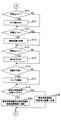
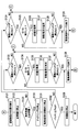
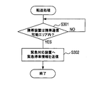
- Flow chart of emergency control process (1) Flow chart of emergency control process (2) Flow chart of emergency control process (3) Flow chart of status recording process Flow chart of transfer process
- a vehicle 1 includes an environment information detection unit 11, a vehicle interior information detection unit 12, a vehicle information detection unit 13, a recording unit 14, an HMI (Human Machine Interface) unit 15, a vehicle interior environment.
- the control unit 16 the exterior equipment 17, the engine control circuit 18, the battery control circuit 19, various travel control devices 20, a driving support control circuit 21, and an emergency control circuit 22 connected to these devices are provided.
- the vehicle 1 is also referred to as a host vehicle. “Information” is used not only as a countable noun but also as a countable noun.
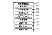
- the environment information detection unit 11 is a device for detecting the environment around the vehicle 1 and includes an outside camera 111, a laser sensor 112, a millimeter wave sensor 113, a navigation device 114, an in-vehicle communication device 115, an outside microphone 116, an illuminance sensor 117, and the like.
- a rain and snow sensor 118 is provided (FIG. 1B).
- the vehicle outside camera 111 includes a front camera that images the front of the vehicle 1, a right camera that images the right side of the vehicle 1, a left camera that images the left side of the vehicle 1, and a rear camera that images the rear of the vehicle 1.
- the laser sensor 112 emits laser light as a transmission signal, receives laser light reflected by an object around the vehicle 1 as a reception signal, and detects an object that reflects the laser light based on the transmission signal and the reception signal.
- the millimeter wave sensor 113 radiates a millimeter wave as a transmission signal, receives a millimeter wave reflected by an object around the vehicle 1 as a reception signal, and detects an object that reflects the millimeter wave based on the transmission signal and the reception signal.
- Navigation device 114 detects the position of vehicle 1 specified by latitude and longitude based on GPS signals received via a GPS (Global Positioning System) antenna. Further, map data and various types of information are recorded in the navigation device 114.
- the map data indicates in which lane on the road the vehicle 1 is located based on the facility classification and position information and the position of the vehicle 1. It contains detailed road information and various data necessary for map display to the extent that it can be specified.
- the navigation device 114 according to the present embodiment can detect the position of the vehicle 1 with an accuracy that can distinguish the lane where the vehicle 1 is located, and which lane on the road is based on the position of the vehicle 1 and road information. It can be determined whether the vehicle 1 is located.
- the in-vehicle communication device 115 performs wireless communication with an external communication device via the mobile phone network and the Internet network, and detects the radio wave intensity of the received radio wave. In the present embodiment, the in-vehicle communication device 115 performs wireless communication with the mobile device 3 described later.
- the outside microphone 116 detects sound around the vehicle 1.
- the illuminance sensor 117 is installed on the instrument panel in front of the driver's seat and detects the illuminance around the vehicle 1 and the illuminance inside the vehicle 1.
- the rain / snow sensor 118 detects rain / snow (rain or snow) adhering to the windshield of the vehicle 1.
- information detected by the apparatus provided in the environment information detection unit 11 is referred to as “environment information”.
- the vehicle interior information detection unit 12 includes a driver monitoring camera 121 and an indoor monitoring camera 122 as devices for detecting the indoor state of the vehicle 1 (FIG. 1C).
- the driver monitoring camera 121 is installed in an instrument panel in front of the driver's seat and images the front of the driver.
- the indoor monitoring camera 122 is attached to the ceiling in the room of the vehicle 1 and picks up an image of the situation inside the room.
- vehicle interior information information detected by a device provided in the vehicle interior information detection unit 12 is referred to as “vehicle interior information”.
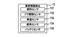
- the vehicle information detection unit 13 includes a fuel sensor 131, a door opening / closing sensor 132, a vehicle speed sensor 133, a rudder angle sensor 134, and a battery sensor 135 as devices for detecting the state of the vehicle (FIG. 1D).
- the fuel sensor 131 detects the remaining amount of fuel in the vehicle 1.
- the door opening / closing sensor 132 detects the opening / closing states of the driver's seat door, the passenger seat door, and the rear seat door.
- the vehicle speed sensor 133 detects the speed of the vehicle 1.
- the steering angle sensor 134 detects the steering angle of the steering wheel.
- the battery sensor 135 detects the remaining battery level of the vehicle 1.
- vehicle information the information detected by the device provided in the vehicle information detection unit 13 is referred to as “vehicle information”.
- the recording unit 14 is a device for recording the situation inside the vehicle 1 and the situation around the vehicle 1.
- the HMI unit 15 includes a display unit 151, an in-vehicle speaker 152, an in-vehicle speaker 153, an in-vehicle microphone 154, and a release switch 155 as a device for providing an interface for communication between a human and a machine (FIG. 1E).
- the display part 151 is arrange
- the in-vehicle speaker 152 is provided in the vehicle 1 and outputs various sounds to the driver.
- the outside speaker 153 outputs various sounds to vehicles around the vehicle 1 and pedestrians.
- the in-vehicle microphone 154 detects a sound in the room of the vehicle 1.
- the release switch 155 is a switch for releasing (terminating) the emergency control mode.
- the emergency control mode referred to here is a mode that is started when an abnormality in the state of the driver is detected, automatically stops after the vehicle 1 has automatically traveled, and thereafter emergency processing described later is executed. While the mode of the vehicle 1 is the emergency control mode, a predetermined operation (for example, driving of the vehicle 1) performed by the driver on the vehicle 1 is invalidated.
- the release switch 155 is installed at a position where it cannot be pressed unless the driver intentionally presses it. In the present embodiment, the release switch 155 is installed in the vicinity of the interior lamp provided on the ceiling of the vehicle 1.
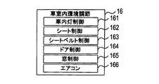
- the vehicle interior environment adjustment unit 16 is an apparatus for adjusting the indoor environment of the vehicle 1, such as an interior light control device 161, a seat control device 162, a seat belt control device 163, a door control device 164, a window control device 165, and an air conditioner.
- a device 166 is provided (FIG. 1F).
- the interior lamp control device 161 controls lighting and extinguishing of the interior lamp.
- the seat control device 162 adjusts the front-rear position and the backrest angle of the driver seat, the passenger seat, and the rear seat.
- the seat belt control device 163 controls the winding of the driver seat belt, the passenger seat belt, and the rear seat belt.
- the door control device 164 controls opening and closing of the driver seat door, the passenger seat door, and the rear seat door, and also controls locking and unlocking of each door. Note that the opening and closing herein includes both a transition from the open state to the closed state and a transition from the closed state to the closed state.
- the window control device 165 controls opening and closing of the windows provided in each of the driver seat door, the passenger seat door, and the rear seat door.
- the air conditioner 166 adjusts the temperature inside the vehicle 1.
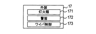
- the exterior equipment 17 includes lights 171, a horn device 172, and a wiper control device 173 (FIG. 1G).
- the lamps 171 are all lighting devices mounted on the vehicle 1 that illuminate the outside of the vehicle, and are, for example, a headlamp, a small lamp, a hazard lamp, and the like.
- the horn device 172 is a notification device that emits a sound (horn) when a horn switch built in the steering wheel is operated and notifies the outside of the vehicle.
- the wiper control device 173 controls the operation of the wiper.
- the engine control circuit 18 controls engine start and stop.
- the battery control circuit 19 stops the power supply to a device mounted on the vehicle 1 and using the battery of the vehicle 1 as a drive power source (hereinafter referred to as “on-vehicle device”).
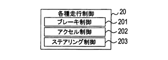
- the various traveling control devices 20 include a brake control device 201, an accelerator control device 202, and a steering control device 203 (FIG. 1H).
- the brake control device 201 controls the braking force applied to the vehicle 1.
- the accelerator control device 202 controls the driving force applied to the vehicle 1 by controlling the accelerator of the vehicle 1.
- the steering control device 203 controls the steering wheel of the vehicle 1.
- the driving support control circuit 21 is an electronic control unit.
- the driving support control circuit 21 is configured to include a known microcomputer mainly including a CPU, a ROM, and a RAM.
- a known microcomputer mainly including a CPU, a ROM, and a RAM.
- the driving support control circuit 21 mediates the emergency control circuit 22 to obtain a captured image around the vehicle 1 by the outside camera 111 and detection results of the laser sensor 112 and the millimeter wave sensor 113.
- the emergency control circuit 22 is an electronic control unit.
- the emergency control circuit 22 includes, as an example, a known microcomputer mainly including a CPU, a ROM, and a RAM.
- Environmental information is acquired from the environmental information detection unit 11
- vehicle interior information is acquired from the vehicle interior information detection unit 12
- vehicle information is acquired from the vehicle information detection unit 13.
- the emergency control circuit 22 executes an emergency control process (FIGS. 2 to 4) and a situation recording process (FIG. 5), which will be described later, based on the acquired environmental information, vehicle interior information, and vehicle information.
- the mobile device 3 of the present embodiment includes a communication unit 31 and a control circuit 32 that are connected to each other.
- the communication unit 31 performs wireless communication with an external communication device via the mobile phone network and the Internet network, and detects the radio wave intensity of the received radio wave.
- the control circuit 32 includes a known microcomputer centered on a CPU, ROM and RAM. The control circuit 32 acquires the radio field intensity from the communication unit 31 and executes a transfer process (FIG. 6) described later.
- the described flowchart includes a plurality of sections (or referred to as steps), and each section is expressed as S101, for example.
- Each section can be divided into multiple subsections, while multiple sections can be combined into a single section.
- Each section can be referred to as a device, a module.
- Each section is related not only as a section of (i) a software unit combined with a hardware unit (for example, a microcomputer) but also as a section of (ii) hardware (for example, an integrated circuit, a wiring logic circuit). It can be realized with or without the function of the device.
- the hardware section can be included inside the microcomputer.
- the emergency control circuit 22 determines whether or not the driver state is abnormal in S101.
- the abnormal state of the driver referred to here is, for example, sudden change in physical condition such as cardiopulmonary arrest or myocardial infarction or doze.
- the emergency control circuit 22 determines that the state in which the driver is closing his eyes or the state in which the driver is not facing is continued for a predetermined time based on the captured image of the driver acquired from the driver monitoring camera 121, Is determined to be abnormal.
- the emergency control circuit 22 determines that the driver is in an abnormal state when it is determined that the vehicle 1 has suddenly accelerated based on the speed of the vehicle 1 acquired from the vehicle speed sensor 133.
- the emergency control circuit 22 determines that the state of the driver is abnormal even when it is determined that the steering wheel is suddenly turned off based on the steering angle of the steering wheel acquired from the steering angle sensor 134. It is assumed that sudden acceleration occurs when the accelerator is not intended by the driver, and sudden change in the steering angle occurs when the driver leans against the steering wheel.
- the emergency control circuit 22 repeats the process of S101 while determining that the driver state is not abnormal (that is, normal) (S101: NO). On the other hand, if the emergency control circuit 22 determines that the driver's state is abnormal (S101: YES), the emergency control circuit 22 outputs a voice message to ask the driver whether or not he / she is conscious (that is, asks whether or not he / she is conscious). (S102) When the driver is aware, the user is prompted to press the release switch 155. For example, the in-vehicle speaker 152 outputs a voice message such as “Are you conscious? Press the release switch 155 if you are conscious”.
- the emergency control circuit 22 determines whether or not the release switch 155 is pressed (S103). If the emergency control circuit 22 determines that the release switch 155 has been pressed (S103: YES), the emergency control circuit 22 returns to S101 described above and repeats the processing from S101 onward.
- the emergency control circuit 22 determines that the release switch 155 is not pressed (S103: NO), it starts the emergency control mode (S104).
- the emergency control circuit 22 displays on the display unit 151 that the mode of the vehicle 1 is the emergency control mode.
- the emergency control circuit 22 causes the driving support control circuit 21 to execute automatic driving of the vehicle 1 by outputting a command to the driving support control circuit 21 to execute automatic driving of the vehicle 1 (S105).
- the driving support control circuit 21 determines the position of the white line in front of the vehicle 1, the vehicle around the vehicle 1, and the like based on the captured image around the vehicle 1 by the outside camera 111 and the detection results of the laser sensor 112 and the millimeter wave sensor 113. Recognize and run automatically.
- the emergency control circuit 22 outputs a command for executing the automatic stop of the vehicle 1 to the driving support control circuit 21, so that the idling of the vehicle 1 is continued to the driving support control circuit 21.
- the vehicle 1 is automatically stopped (S106).
- the driving support control circuit 21 acquires the map data and the position of the vehicle 1 from the navigation device 114, and based on the acquired information, the vehicle 1 is placed in a safe place (for example, a road shoulder) around the current position of the vehicle 1. To stop.
- the vehicle 1 stops in a state where idling is continued the battery is charged by consuming the fuel of the vehicle 1 while idling continues even after the vehicle is stopped.
- the function of the vehicle 1 that automatically stops after detecting an abnormality in the driver's condition is referred to as an “emergency stop function”.
- the emergency control circuit 22 turns on the hazard lamp of the vehicle 1 (S107). Thereafter, the emergency control circuit 22 causes the seat control device 162, the seat belt control device 163, the window control device 165, and the air conditioner 166 to adjust the indoor environment of the vehicle 1 (S108).
- the emergency control circuit 22 causes the seat control device 162 to adjust the front-rear position of the driver seat and the angle of the backrest so that the driver can take a comfortable posture.
- the emergency control circuit 22 causes the seat belt control device 163 to control the winding of the driver's seat belt so that the tightening of the seat belt is eased.
- the emergency control circuit 22 causes the window control device 165 to perform an operation of opening or closing the window so that the room temperature becomes a comfortable temperature when the temperature inside the vehicle 1 is high or low, and an air conditioner. Let the device 166 adjust the temperature in the room.
- the emergency control circuit 22 causes the door control device 164 to lock the door on the traveling lane side of the vehicle 1 in order to prevent the driver from accidentally jumping out from the vehicle 1 to the traveling lane (S109).
- the emergency control circuit 22 determines which lane on the road the vehicle 1 is located on the basis of the road information acquired from the navigation device 114 and the position of the vehicle 1, and determines the left and right doors of the vehicle 1. It is determined whether or not each is a door on the traveling lane side.
- a rescuer etc. comes, so that a rescuer etc. can open the door of the vehicle 1, a door cannot be opened from the inside of a vehicle, but it can open from the outside of a vehicle.
- the door on the lane side is locked.
- the emergency control circuit 22 determines whether or not the illuminance around the vehicle 1 is less than or equal to a predetermined threshold Th1 based on the illuminance around the vehicle 1 acquired from the illuminance sensor 117 (S110).
- the threshold Th1 is determined based on the illuminance when the day and night are switched.
- the emergency control circuit 22 determines that the illuminance around the vehicle 1 is equal to or less than the threshold value Th1, that is, when it is determined that it is nighttime (S110: YES), the lights 171 are turned on (S111). , The process proceeds to S112.
- the emergency control circuit 22 determines that the illuminance around the vehicle 1 is not equal to or less than the threshold Th1, that is, when it is determined that it is not nighttime (S110: NO), the process of S111 described above is skipped, Migrate to
- the emergency control circuit 22 determines whether or not the volume around the vehicle 1 is greater than or equal to a predetermined threshold Th2 based on the sound around the vehicle 1 acquired from the outside microphone 116 (S112).
- the threshold value Th2 is set with reference to the boundary between the volume when there is noise and the volume when there is no noise.
- the emergency control circuit 22 determines that the volume around the vehicle 1 is not equal to or greater than the threshold value Th2, that is, when it is determined that there is no noise around the vehicle 1 (S112: NO), the horn device 172 is blown. (S113), it informs the outside of the vehicle 1 that the vehicle 1 is stopped.
- the emergency control circuit 22 determines that the volume around the vehicle 1 is greater than or equal to the threshold Th2, that is, determines that there is noise around the vehicle 1 (S112: YES), S113 described above This process is skipped, and the process proceeds to S114.
- the emergency control circuit 22 determines whether the illuminance in the room of the vehicle 1 is equal to or less than the threshold value Th1 based on the illuminance in the room of the vehicle 1 acquired from the illuminance sensor 117.
- the threshold value Th1 in S114 is the same value as the threshold value Th1 in S110.
- the interior light control device 161 lights the interior light (S115), and the process proceeds to S116.
- the process of S115 described above is skipped, and the process proceeds to S116.
- the emergency control circuit 22 determines whether rain or snow is attached to the windshield of the vehicle 1 based on the detection result acquired from the rain and snow sensor 118.
- the wiper control device 173 drives the wiper (S117), and proceeds to S118.
- the process of S117 described above is skipped and the process proceeds to S118.
- the emergency control circuit 22 determines whether or not the vehicle 1 exists in the portable communication area based on the radio wave intensity acquired from the in-vehicle communication device 115.
- the mobile communication possible area here is an area where communication by a mobile phone is possible. If the emergency control circuit 22 determines that the vehicle 1 is in the portable communication area (S118: YES), the in-vehicle communication device 115 causes the emergency stop information to be transmitted to the emergency response device outside the vehicle 1 (S119). ).
- the emergency stop information here is information representing at least the position of the vehicle 1.
- the emergency response device is a device corresponding to a destination of emergency stop information installed in a general management center that supervises and manages emergency stop information transmitted from a plurality of vehicles including the vehicle 1.
- the emergency control circuit 22 determines that the vehicle 1 does not exist within the mobile communication area of the mobile phone (S118: NO)
- the in-vehicle communication device 115 is wirelessly passing through the periphery of the vehicle 1.
- Emergency stop information and transfer information are transmitted to the communication device (S120).
- a wireless communication device passing through the periphery of the vehicle for example, a mobile device (for example, a smartphone) possessed by a person passing through the periphery of the vehicle 1 or a communication mounted on a vehicle passing through the periphery of the vehicle 1 Examples include equipment.
- the transfer information is information indicating that the emergency stop information is transferred to the emergency response device when the wireless communication device that has received the transfer information moves and enters the portable communication area.
- the emergency stop information is transferred to the emergency response device by the mobile device 3 passing through the periphery of the vehicle 1 receiving the transfer information and executing a transfer process (FIG. 6) described later.
- the emergency control circuit 22 detects the position of the predetermined retreat facility closest to the position where the vehicle 1 is stopped based on the map data acquired from the navigation device 114 and the position of the vehicle 1 (S121).
- the evacuation facility is a facility (for example, a hospital or the like) where the driver can receive treatment and a facility (for example, a gas station or the like) that can refuel the vehicle 1.
- the emergency control circuit 22 calculates the amount of fuel (necessary amount) necessary for the vehicle 1 to travel from the position where the vehicle 1 is stopped to the position of the evacuation facility detected in S121 (S122). .
- the emergency control circuit 22 determines whether or not the remaining amount of fuel is less than the required amount based on the remaining amount of fuel acquired from the fuel sensor 131 (S123). If the emergency control circuit 22 determines that the remaining fuel amount is not less than the required amount (S123: NO), it determines whether the release switch 155 has been pressed (S124). If the emergency control circuit 22 determines that the release switch 155 has not been pressed (S124: NO), the emergency control circuit 22 returns to S110 described above and repeats the processes after S110.
- the emergency control circuit 22 determines that the release switch 155 has been pressed (S124: YES), whether the emergency stop information has been transmitted to the emergency response device, that is, whether the process of S119 has been executed. Is determined (S125).
- the driver recommends that the driver waits at a position where the vehicle 1 is stopped without moving the vehicle 1.
- a voice message is output to the in-vehicle speaker 152 (that is, standby is recommended) (S126).
- the in-vehicle speaker 152 outputs a message such as “Avoid excessive driving and wait in this place”.
- the emergency control circuit 22 outputs a voice message asking whether the driver intends to move the vehicle 1 (that is, asks about the intention to move) (S127). Prompt to press 155.
- the in-vehicle speaker 152 outputs a message such as “Do you want to move? If you want to move, press the release switch 155.”
- the emergency control circuit 22 determines whether or not the release switch 155 has been pressed (S128). If it is determined that the release switch 155 has been pressed (S128: YES), the emergency control mode is terminated (S128: YES). S129). Thereafter, the emergency control circuit 22 returns to S101 described above and repeats the processing after S101.
- the emergency control circuit 22 determines in S125 that the process of S119 is not executed (S125: NO), it skips the processes of S126 to S128 described above and executes S129 described above. And the emergency control circuit 22 returns to S101 mentioned above, and repeats the process after S101. In other words, the emergency control circuit 22 does not transmit emergency stop information to the emergency response device, so if it is uncertain whether or not rescue will come, the in-car speaker 152 will indicate a standby recommendation voice message and an intention to move. The emergency control mode is terminated without outputting a voice message asking whether there is presence or absence.
- the emergency control circuit 22 determines that the remaining fuel amount is less than or equal to the required amount in S123 (S123: YES), it stops idling in order to suppress fuel consumption (S130). Thereafter, the emergency control circuit 22 stops the emergency process step by step according to the remaining battery level acquired from the battery sensor 135 (S131). In other words, the emergency control circuit 22 does not stop the emergency process during idling, but stops the emergency process step by step after the idling is stopped.
- the emergency process here is a process executed by the emergency control circuit 22 in order to control the in-vehicle device when the vehicle 1 is stopped by the emergency stop function.
- the emergency processing includes lighting processing of interior lights and lights 171 provided in the vehicle 1, blowing processing of the horn device 172 of the vehicle 1, driving processing of the wiper of the vehicle 1, and wireless for a rescue request Signal transmission processing, adjustment processing of the indoor environment of the vehicle 1, locking processing of the door of the vehicle 1 on the traveling lane side, processing for opening the window of the vehicle 1, processing for closing the window of the vehicle 1, in-vehicle speakers 152 and outside of the vehicle 1
- a process for outputting a voice message to the speaker 153, a recording process for recording at least one of the situation inside the vehicle 1 and the situation around the vehicle 1, and information representing the situation inside the vehicle 1 and the situation around the vehicle 1 Includes an information transmission process for transmitting at least one of the information representing the information to the information management center.
- the emergency control circuit 22 gives priority to the emergency process without stopping the adjustment process of the indoor environment of the vehicle 1, the transmission process of the radio signal for the rescue request, the recording process, and the information transmission process. These processes are continued. That is, the emergency control circuit 22 preferentially executes emergency processing for the purpose of protecting the life of the driver, requesting rescue to the outside, and protecting the articles in the vehicle 1.
- the emergency control circuit 22 sequentially stops the emergency processing based on the following rules for the other emergency processing. That is, the emergency control circuit 22 performs the first emergency process when the first emergency process and the second emergency process in which the power consumption of the battery is smaller than that of the first emergency process are executed. After the stop, the second emergency process is stopped. That is, the emergency control circuit 22 stops the other emergency processes step by step from the process that consumes a large amount of battery power. In the present embodiment, the emergency control circuit 22 stops the emergency process, so that the operation of the in-vehicle device stops.
- the emergency control circuit 22 determines whether or not the remaining battery level is equal to or less than the predetermined amount Th3 based on the remaining battery level acquired from the battery sensor 135 (S132).
- the predetermined amount Th3 is set based on an amount necessary for re-igniting the engine.
- the emergency control circuit 22 determines that the remaining amount of the battery is not equal to or less than the predetermined amount Th3 (S132: NO).
- the emergency control circuit 22 executes the processing of S133 to S138.
- S133 to S138 are the same as S124 to S129 described above, description thereof is omitted.
- the emergency control circuit 22 determines that the remaining amount of the battery is equal to or less than the predetermined amount Th3 (S132: YES)
- the emergency control circuit 22 stops all the functions of the vehicle 1 (S139) and ends the emergency control process. .
- the stop of all the functions of the vehicle 1 here means that the state of the vehicle 1 is changed to the state of the vehicle 1 that is normally realized when the engine is turned off. Including emergency processing for the purpose of protecting human life).
- the situation recording process is started when the ignition switch of the vehicle 1 is turned on, and is executed in parallel with the emergency control process.
- the emergency control circuit 22 determines whether or not the mode of the vehicle 1 is the emergency control mode (S201).
- the emergency control circuit 22 repeats the process of S201 while determining that the mode of the vehicle 1 is not the emergency control mode (S201: NO).
- the emergency control circuit 22 causes the recording unit 14 to start recording the situation around the vehicle 1 (S202).
- the recording unit 14 records a captured image of the periphery of the vehicle 1 by the outside camera 111 and detection results by the laser sensor 112 and the millimeter wave sensor 113.
- the emergency control circuit 22 determines whether or not the vehicle 1 has been stopped by the emergency stop function (S203), and while it is determined that the vehicle 1 has not stopped by the emergency stop function (S203: NO), the process of S203 is repeated.
- the emergency control circuit 22 determines whether there is a person around the vehicle 1 (S204).
- the person in the vicinity of the vehicle 1 includes, for example, an intruder who tries to enter the vehicle 1 for the purpose of stealing money or the like in the vehicle 1.
- the emergency control circuit 22 repeats the process of S204 while determining that there is no person around the vehicle 1 (S204: NO).
- the emergency control circuit 22 causes the recording unit 14 to start recording the situation inside the vehicle 1 (S205).
- the recording unit 14 records a captured image of the entire indoor situation by the indoor monitoring camera 122.
- the emergency control circuit 22 determines whether any door of the vehicle 1 is open based on the detection result acquired from the door opening / closing sensor 132 (S206).
- the emergency control circuit 22 repeats the process of S206 while determining that none of the doors of the vehicle 1 is open (S206: NO).
- the emergency control circuit 22 determines that any one of the doors of the vehicle 1 is open (S206: YES), the situation around the vehicle 1 and the situation inside the vehicle 1 are recorded.
- the voice message is output to the in-vehicle speaker 152 and the out-of-vehicle speaker 153 (S207).
- the door of the vehicle 1 is opened, for example, the door may be opened by the intruder, and the voice message in S207 is output for the purpose of alerting the intruder.
- the emergency control circuit 22 determines whether or not the state of the recording unit 14 is abnormal (S208). In the present embodiment, the emergency control circuit 22 determines that the state of the recording unit 14 is abnormal when the recording unit 14 is damaged. Examples of the case where the recording unit 14 is damaged include a case where the recording unit 14 is damaged by an intruder.
- the emergency control circuit 22 determines that the state of the recording unit 14 is abnormal (S208: YES)
- the in-vehicle communication device 115 sends the situation information (information indicating the indoor situation of the vehicle 1 and the surroundings of the vehicle 1). Information representing the situation) is transmitted to the information management center (S209), and the situation recording process is terminated.
- the emergency control circuit 22 causes the in-vehicle communication device 115 to transmit the situation information so that the situation when the state of the recording unit 14 becomes abnormal can be understood.
- the emergency control circuit 22 determines whether or not the emergency control mode has ended (S210). If the emergency control circuit 22 determines that the emergency control mode has ended (S210: YES), the situation recording process ends. On the other hand, when determining that the emergency control mode has not ended (S210: NO), the emergency control circuit 22 returns to the above-described S208 and repeats the processing from S208 onward.
- the transfer process can be executed by installing a dedicated application on an existing portable device (for example, a smartphone), and is started by receiving emergency stop information and transfer information from the vehicle 1.
- a dedicated application for example, a smartphone
- the control circuit 32 determines whether or not the portable device 3 exists in the portable communication possible area based on the radio wave intensity acquired from the communication unit 31 (S301). The control circuit 32 repeats the process of S301 while it is determined that the mobile device 3 does not exist within the mobile communication enabled area (S301: NO). On the other hand, if the control circuit 32 determines that the mobile device 3 is present in the mobile communicable area (S301: YES), the control circuit 32 causes the communication unit 31 to transmit emergency stop information to the emergency response device (S302), and performs transfer processing. finish.
- all emergency processes can be executed when the vehicle 1 is stopped by the emergency stop function, and at least a part of the emergency processes being executed follows a predetermined stop order. Stopped in stages. Therefore, it is possible to prolong the duration of emergency processing without reducing the number of emergency processing that can be executed when the vehicle is stopped. Moreover, in this embodiment, since the battery power consumption is stopped step by step except for some processes, the effect of extending the duration of the emergency process can be improved. Moreover, in this embodiment, since emergency processing for the purpose of protecting the life of the driver, requesting rescue to the outside, and protecting the articles in the vehicle 1 is performed with priority, the duration of these processing is extended. be able to.
- the emergency control circuit 22 continues idling in which the battery is charged when the vehicle 1 is stopped. Therefore, it is possible to prolong the duration of the emergency process as compared with the case where idling is not continued when the vehicle stops.
- the emergency control circuit 22 uses the amount of fuel necessary for the vehicle 1 to travel from the position of the vehicle 1 stopped by the emergency stop function to the nearest retreat facility from the stop position ( Necessary amount) is calculated. And when the fuel remaining amount of the vehicle 1 becomes less than a required amount, idling is stopped in order to suppress fuel consumption. Therefore, in the present embodiment, when the vehicle 1 is stopped by the emergency stop function, the fuel for the vehicle 1 to travel from the stop position to the evacuation facility is ensured when the remaining fuel amount is more than a necessary amount. As a result, when the driver's state is recovered, the driver can drive the vehicle 1 and move to the retreat facility.
- the evacuation facility is a facility where the driver can receive treatment (for example, a hospital) and a facility (for example, a gas station) where the fuel of the vehicle 1 can be replenished. It is possible to travel the vehicle 1 to a proper facility.
- the emergency control circuit 22 turns on the lights 171 when it is nighttime, and blows the horn device 172 when there is no noise around the vehicle 1. That is, the emergency control circuit 22 determines whether or not to notify a notification device such as the lights 171 and the horn device 172 based on the situation around the vehicle 1. Therefore, it is possible to notify a notification device having a high notification effect outside the vehicle 1 and to suppress battery consumption by not allowing a notification device having a low notification effect to be notified.
- the emergency control circuit 22 turns on the interior lamp when the illuminance in the vehicle 1 is equal to or less than the threshold value Th1. Therefore, even when the interior of the vehicle 1 is dark, it is possible to easily recognize the situation inside the vehicle 1 (for example, the state of the driver) from the outside of the vehicle 1.
- the emergency control circuit 22 drives the wiper when rain and snow are attached to the windshield. Therefore, even when it is raining, it is possible to make it easy to visually recognize the situation inside the vehicle 1 from the outside of the vehicle 1.
- the emergency control circuit 22 causes the in-vehicle communication device 115 to transmit emergency stop information to the emergency response device when the vehicle 1 exists in the portable communication area.
- the emergency control circuit 22 transmits emergency stop information and transfer information to the in-vehicle communication device 115 to a wireless communication device passing through the periphery of the vehicle 1 when the vehicle 1 does not exist in the portable communication area. Let Therefore, even when emergency stop information cannot be transmitted directly to the emergency response device because the vehicle 1 does not exist within the portable communication area, the emergency stop can be performed through the wireless communication device that is passing around the vehicle 1. Information can be sent to the emergency response device.
- the emergency control circuit 22 stops the vehicle 1 without moving the vehicle 1 by the driver when the release switch 155 is pressed after the emergency stop information is transmitted to the emergency response device.
- a voice message to recommend that you wait at a certain position is output. Therefore, for example, when the recovery of the driver's state is not sufficient, it is possible to increase the possibility that the driver avoids excessive driving and waits for rescue.
- the emergency control circuit 22 causes the recording unit 14 to record the situation inside the vehicle 1 and the situation around the vehicle 1. Therefore, it is possible to suppress an intruder or the like who tries to enter the vehicle 1 for the purpose of stealing a gold item or the like in the vehicle 1 and to protect the driver and articles in the vehicle 1. Moreover, in this embodiment, when the door of the vehicle 1 is opened, a sound is output that the recording is being performed. Therefore, by warning the intruder or the like who opened the door, the effect of suppressing the intruder or the like from doing wrong can be further enhanced.
- the situation information recorded by the recording unit 14 (information representing the indoor situation of the vehicle 1 and information representing the situation around the vehicle 1) is information. Sent to the management center. In particular, situation information is transmitted so that the situation when the state of the recording unit 14 becomes abnormal can be understood. Therefore, based on the situation information, an outside person can know the situation when the recording unit 14 is damaged.
- the emergency control circuit 22 corresponds to an example of a vehicle control device that performs control when the vehicle is stopped.
- the vehicle-mounted communication device 115, the recording unit 14, the vehicle interior speaker 152, the vehicle exterior speaker 153, the vehicle interior environment adjustment unit 16, and the exterior equipment 17 are devices that use a vehicle battery as a drive power source and are examples of devices mounted on the vehicle. It corresponds to.
- the emergency control circuit 22 functions as each part as follows. S107 to S120, S124 to S126, S133 to S135, S202, S205, and S209 correspond to an example of processing as a processing execution unit.
- S131 corresponds to an example of processing as a processing stop unit
- S106 corresponds to an example of processing as an idling continuation unit
- S121 to S123 correspond to an example of processing as an idling determination unit
- S121 corresponds to an example of processing as a facility position detection unit
- S122 corresponds to an example of processing as a calculation unit
- S123 corresponds to an example of processing as a fuel determination unit
- S110 to S113 are notification processing. This corresponds to an example of processing as a unit.
- the lights 171 and the horn device 172 correspond to an example of a notification device
- S110 and S112 correspond to an example of processing as a notification determination unit
- S111 and S113 correspond to an example of processing as a notification execution unit
- the interior lamps and lights 171 correspond to an example of lighting equipment
- S114 and S115 correspond to an example of a lighting processing unit
- S114 corresponds to an example of processing as an illuminance determination unit
- S115 as a lighting execution unit. This corresponds to an example of the process.
- S116 and S117 correspond to an example of a drive processing unit
- S116 corresponds to an example of a process as a rain / snow determination unit
- S117 corresponds to an example of a process as a drive execution unit.
- the in-vehicle communication device 115 corresponds to an example of a communication device
- emergency stop information and transfer information correspond to an example of a radio signal for a rescue request.
- S118 to S120 correspond to an example of processing as a rescue transmission processing unit
- S118 corresponds to an example of processing as a portable communication determination unit
- S119 and S120 correspond to an example of processing as a rescue transmission execution unit. .
- S124 to S126 and S133 to S135 correspond to an example of processing as an audio output processing unit
- pressing of the release switch 155 corresponds to an example of a predetermined operation on the vehicle for stopping all emergency processes being executed.
- S124, S125, S133, and S134 correspond to an example of processing as an operation determination unit
- S126 and S135 correspond to an example of processing as an audio output execution unit.
- the recording unit 14 corresponds to an example of a recording device
- S202 and S205 correspond to an example of processing as a recording processing unit
- the in-vehicle communication device 115 corresponds to an example of an information transmission device
- S209 serves as a status transmission unit. This corresponds to an example of the process.
- the determination as to whether or not the driver state is abnormal is made based on the image captured by the driver monitoring camera 121, but whether or not the driver state is abnormal.
- the determination method is not limited to this.
- an electrocardiographic sensor may be installed on the driver's seat to detect a driver's electrocardiogram signal, and when an abnormality is detected in the electrocardiogram signal, the driver's condition may be determined to be abnormal.
- the in-vehicle speaker 152 asks the driver whether or not he / she is conscious by outputting a sound.
- the questioning method is not limited to this. .
- the presence or absence of consciousness may be asked by the display unit 151 displaying an image message.
- the emergency control circuit 22 determines whether each of the left and right doors of the vehicle 1 is a driving lane side door based on the position of the vehicle 1 and road information.
- the determination is not limited, and the determination may be made by other methods. For example, assuming that the vehicle 1 is traveling in the lane on the shoulder side, the door on the shoulder side is not the door on the traveling lane, and the door on the opposite side to the shoulder side is the door on the traveling lane. You may decide to.
- the door on the traveling lane side is locked so that the door cannot be opened from the inside of the vehicle but can be opened from the outside of the vehicle.
- the door may be locked so that it does not open.
- the emergency control circuit 22 opens the unlocked door on the opposite side when the rescuer tries to open the door on the traveling lane side from outside the vehicle after locking.
- the rescuer or the like may be urged by voice or the like from the outside speaker 153.
- the emergency control mode is released by pressing the release switch 155, but the method of releasing the emergency control mode is not limited to this.
- the emergency control mode may be canceled by displaying the software switch on the display unit 151 and pressing the software switch. Further, the emergency control mode may be canceled by inputting a voice to the in-vehicle microphone 154. Further, the emergency control mode may be canceled by performing a plurality of operations such as pressing the release switch 155 and inputting a voice to the in-vehicle microphone 154.
- whether or not it is nighttime is determined based on the detection value acquired from the illuminance sensor 117, but the method for determining that it is nighttime is not limited to this. For example, it may be determined that it is night when the time has passed a predetermined time. Further, it may be determined that it is night when the vehicle width lamp of the vehicle 1 is lit.
- the illuminance threshold value related to the lighting of the lamps 171 and the illuminance threshold value related to the lighting of the interior lamp are the same value Th1, but the present invention is not limited to this.
- the threshold may be another value.
- the illuminance around the vehicle 1 and the illuminance inside the vehicle 1 are detected by the single illuminance sensor 117.
- the present invention is not limited to this.
- the illuminance around the vehicle 1 and the illuminance inside the vehicle 1 May be detected by a separate illuminance sensor.
- the emergency control circuit 22 determines whether or not the horn device 172 is sounded based on the presence or absence of noise around the vehicle 1, but the horn determination criterion of the horn device 172 is not limited to this. I can't.
- the emergency control circuit 22 may determine whether to sound the horn device 172 based on the position of the vehicle 1 on the map. In this case, for example, when the vehicle 1 is stopped by the emergency stop function in a place where there are many people such as an urban area, the emergency control circuit 22 may determine that the horn device 172 is sounded.
- the emergency control circuit 22 turns on the lights 171 when it is nighttime, and blows the horn device 172 when there is no noise around the vehicle 1.
- the method of notifying the notification device based on the situation is not limited to this. For example, when the vehicle 1 is stopped at a place (for example, an expressway or the like) that requires attention to the rear compared to the front of the vehicle 1, even if the notification is executed by a notification device mounted on the rear portion of the vehicle 1. Good.
- the front of the vehicle 1 Notification may be executed by the notification device mounted on the rear and the notification device mounted on the rear.
- notification to the outside of the vehicle is performed by lighting the lights 171 or the like, but the notification method is not limited to this.
- a display device for example, an electric bulletin board or the like
- notification may be executed by the display device.
- the notification may be executed by outputting a sound to a speaker of a vehicle passing through the periphery of the vehicle 1 using inter-vehicle communication.
- notification may be executed by transmitting emergency stop information to a community-type website such as SNS (Social Networking Service) through the Internet network.
- SNS Social Networking Service
- notification may be performed by transmitting emergency stop information to a road administrator such as a road corporation and broadcasting that the vehicle 1 is stopped by a broadcasting station or the like.
- the in-vehicle communication device 115 transmits emergency stop information to a communication device (for example, a smartphone) brought into the vehicle 1 by the driver of the vehicle 1, and the communication device transmits the emergency stop information to the outside of the vehicle. May be executed.
- the emergency stop information is information representing at least the position of the vehicle 1, but is not limited thereto.
- the emergency stop information is information representing at least the position of the vehicle 1 and the state of the driver. There may be.
- the recording unit 14 records a captured image or the like around the vehicle 1 by the outside camera 111, but the object to be recorded by the recording unit 14 is not limited to this.
- the recording unit 14 may record sound detected by the outside microphone 116 or the inside microphone 154.
- the situation information (information representing the situation inside the vehicle 1 and information representing the situation around the vehicle 1) is stored in the information management center when it is determined that the state of the recording unit 14 is abnormal. Sent to.
- the situation information is not limited to this.
- the situation information may be constantly transmitted to the information management center after it is determined that there is a person around the vehicle 1.
- the situation information recorded by the recording unit 14 is transmitted.
- the present invention is not limited to this.
- the situation information around the vehicle 1 detected by the vehicle exterior camera 111 or the like is immediately transmitted to record the situation information.
- the situation information that is not recorded by the unit 14 may be transmitted.
- the recording unit 14 records both the situation around the vehicle 1 and the situation inside the vehicle 1, but the present invention is not limited to this, and only one of them may be recorded.
- the emergency control circuit 22 determines that the state of the recording unit 14 is abnormal when the recording unit 14 is damaged, but determines that the state of the recording unit 14 is abnormal.
- the case is not limited to this.
- it may be determined that the state of the recording unit 14 is abnormal when the amount of information recorded by the recording unit 14 exceeds a recordable limit amount.
- the emergency process is a lighting process of the interior lamp and the lights 171 provided in the vehicle 1, but the emergency process is not limited thereto.
- the emergency control circuit 22 performs emergency processing for unlocking the door control device 164 to unlock the door of the vehicle 1 when the door of the vehicle 1 is locked when a rescuer or the like comes. May be executed as
- the operation of the in-vehicle device is stopped by the emergency control circuit 22 stopping the emergency process, but the method of stopping the operation of the in-vehicle device is not limited to this.
- the battery control circuit 19 may stop the operation by stopping the power supply to the in-vehicle device.
Landscapes
- Engineering & Computer Science (AREA)
- Mechanical Engineering (AREA)
- Transportation (AREA)
- Automation & Control Theory (AREA)
- Physics & Mathematics (AREA)
- General Physics & Mathematics (AREA)
- Chemical & Material Sciences (AREA)
- Combustion & Propulsion (AREA)
- Signal Processing (AREA)
- Computer Networks & Wireless Communication (AREA)
- General Engineering & Computer Science (AREA)
- Remote Sensing (AREA)
- Radar, Positioning & Navigation (AREA)
- Aviation & Aerospace Engineering (AREA)
- Acoustics & Sound (AREA)
- Human Computer Interaction (AREA)
- Medical Informatics (AREA)
- Health & Medical Sciences (AREA)
- General Health & Medical Sciences (AREA)
- Computing Systems (AREA)
- Multimedia (AREA)
- Electromagnetism (AREA)
- Mathematical Physics (AREA)
- Computer Vision & Pattern Recognition (AREA)
- Optics & Photonics (AREA)
- Alarm Systems (AREA)
- Evolutionary Computation (AREA)
- Artificial Intelligence (AREA)
- Game Theory and Decision Science (AREA)
- Business, Economics & Management (AREA)
- Navigation (AREA)
- Auxiliary Drives, Propulsion Controls, And Safety Devices (AREA)
- Electrical Control Of Air Or Fuel Supplied To Internal-Combustion Engine (AREA)
- Arrangements Of Lighting Devices For Vehicle Interiors, Mounting And Supporting Thereof, Circuits Therefore (AREA)
- Traffic Control Systems (AREA)
Abstract
A vehicle control apparatus which is installed in a vehicle having the emergency stop function of detecting abnormalities in the state of a driver and automatically stopping the vehicle and controls the stopped vehicle, the vehicle control apparatus being equipped with a plurality of processing execution units (S124 to S126, S133 to S135) and a processing stop unit (S131). If the vehicle is stopped by the emergency stop function, the plurality of processing execution units execute predetermined emergency processing for controlling in-vehicle equipment that uses the battery of the vehicle as a drive source. The processing stop unit at least partially stops the emergency processing executed by the plurality of processing execution units, in stages in accordance with a predetermined stop sequence.
Description
本出願は、2014年10月31日に出願された日本特許出願番号2014-223019号に基づくもので、ここにその記載内容を援用する。
This application is based on Japanese Patent Application No. 2014-2223019 filed on October 31, 2014, the contents of which are incorporated herein by reference.
本開示は、車両の停車時の制御をする車両制御装置(Vehicle Control Apparatus)に関する。
The present disclosure relates to a vehicle control device (Vehicle Control Apparatus) that performs control when the vehicle is stopped.
車両を運転するドライバの状態が異常になり、その異常が検出された場合に、後発事故の抑制や救助要請等を目的として車両を自動的に制御する技術が知られている。特許文献1に記載の車両制御システムは、心臓麻痺等のドライバの状態の異常が検出された場合に自動的に車両を停車させる緊急停車機能を実現する。そして、この車両制御システムは、緊急停車機能により車両が停車した場合に、車両のバッテリを電源として、音声や方向指示器等でドライバの異常を車両周辺へ報知するための緊急処理や救急センタ等の通報先に通報するための緊急処理を実行する。
There is known a technology for automatically controlling a vehicle for the purpose of suppressing a subsequent accident or requesting a rescue when the state of a driver driving the vehicle becomes abnormal and the abnormality is detected. The vehicle control system described in Patent Literature 1 realizes an emergency stop function that automatically stops the vehicle when an abnormality in the driver's state such as heart failure is detected. And when this vehicle control system stops by the emergency stop function, emergency processing and emergency center etc. for notifying the driver's abnormality to the surroundings of the vehicle by voice, direction indicator, etc. using the battery of the vehicle as a power source Execute emergency processing to report to the report destination.
しかしながら、特許文献1に記載の車両制御システムは、緊急停車機能により車両が停車した場合に、車両のバッテリを電源とする複数の緊急処理を際限なく実行するため、バッテリが上がってしまうことがある。そして、バッテリが上がってしまった場合、ドライバの状態が回復してドライバが車両を運転しようとしてもエンジンがかからないという不都合が生じる。
However, since the vehicle control system described in Patent Literature 1 performs a plurality of emergency processes using the battery of the vehicle as a power source when the vehicle is stopped by the emergency stop function, the battery may be increased. . When the battery has run out, the driver's state recovers, and there is a problem that the engine does not start even if the driver tries to drive the vehicle.
なお、バッテリの消費を抑制するとともに緊急処理の継続時間を増加させるために、実行する緊急処理の数を減らすことも考えられるが、そのようにすると全く実行されない緊急処理が生じてしまう。
Although it is conceivable to reduce the number of emergency processes to be executed in order to suppress battery consumption and increase the duration of emergency processes, such an emergency process that is not executed at all occurs.
本開示は、ドライバの状態の異常が検出され、車両が自動的に停車した場合に、停車時に実行可能な緊急処理の数を減らさずに緊急処理の継続時間を長引かせることを目的とする。
This disclosure is intended to prolong the duration of emergency processing without reducing the number of emergency processing that can be performed when the vehicle stops when an abnormality in the driver's condition is detected and the vehicle automatically stops.
本開示のひとつの例では、ドライバの状態の異常を検出して自動的に停車する緊急停車機能を有する車両に搭載された車両制御装置は、複数の処理実行部と、処理停止部と、を備えるように提供される。複数の処理実行部は、緊急停車機能により車両が停車した場合に、車両のバッテリを駆動電源とする機器であって車両に搭載された機器を制御するための所定の緊急処理を実行する。処理停止部は、複数の処理実行部により実行される緊急処理のうちの少なくとも一部を、所定の停止順序に従い段階的に停止させる。このような構成によれば、停車時に実行可能な緊急処理の数を減らさずに緊急処理の継続時間を長引かせることができる。
In one example of the present disclosure, a vehicle control device mounted on a vehicle having an emergency stop function that automatically detects a driver's condition and stops automatically includes a plurality of process execution units, and a process stop unit. Provided to provide. When the vehicle stops by the emergency stop function, the plurality of processing execution units execute a predetermined emergency process for controlling a device mounted on the vehicle that is a device that uses the vehicle battery as a drive power source. A process stop part stops at least one part of the emergency processes performed by the several process execution part in steps according to a predetermined stop order. According to such a configuration, the duration of the emergency process can be extended without reducing the number of emergency processes that can be executed when the vehicle is stopped.
本開示についての上記目的およびその他の目的、特徴や利点は、添付の図面を参照しながら下記の詳細な記述により、より明確になる。
車両及び携帯装置の構成を表すブロック図
環境情報検出部の構成を表すブロック図
車室内情報検出部の構成を表すブロック図
車両情報検出部の構成を表すブロック図
HMI部の構成を表すブロック図
車室内環境調節部の構成を表すブロック図
外装装備の構成を表すブロック図
各種走行制御装置の構成を表すブロック図
緊急時制御処理のフローチャート(1)
緊急時制御処理のフローチャート(2)
緊急時制御処理のフローチャート(3)
状況記録処理のフローチャート
転送処理のフローチャート
The above and other objects, features and advantages of the present disclosure will become more apparent from the following detailed description with reference to the accompanying drawings.
Block diagram showing configurations of vehicle and portable device Block diagram showing the configuration of the environmental information detector Block diagram showing the configuration of the vehicle interior information detection unit Block diagram showing the configuration of the vehicle information detection unit Block diagram showing the configuration of the HMI unit Block diagram showing the configuration of the passenger compartment environment control unit Block diagram showing the structure of exterior equipment Block diagram showing the configuration of various travel control devices Flow chart of emergency control process (1) Flow chart of emergency control process (2) Flow chart of emergency control process (3) Flow chart of status recording process Flow chart of transfer process
以下、本開示の例示的な実施形態について図面を参照しながら説明する。
Hereinafter, exemplary embodiments of the present disclosure will be described with reference to the drawings.
[1.構成]
図1Aに示すように、本実施形態の車両1は、環境情報検出部11、車室内情報検出部12、車両情報検出部13、記録部14、HMI(Human Machine Interface)部15、車室内環境調節部16、外装装備17、エンジン制御回路18、バッテリ制御回路19、各種走行制御装置20、運転支援制御回路21及びこれらの装置に接続された緊急時制御回路22を備える。車両1は、ホスト車両とも言及される。「情報」は、不可算名詞のみならず、可算名詞としても使用される。 [1. Constitution]
As shown in FIG. 1A, a vehicle 1 according to this embodiment includes an environmentinformation detection unit 11, a vehicle interior information detection unit 12, a vehicle information detection unit 13, a recording unit 14, an HMI (Human Machine Interface) unit 15, a vehicle interior environment. The control unit 16, the exterior equipment 17, the engine control circuit 18, the battery control circuit 19, various travel control devices 20, a driving support control circuit 21, and an emergency control circuit 22 connected to these devices are provided. The vehicle 1 is also referred to as a host vehicle. “Information” is used not only as a countable noun but also as a countable noun.
図1Aに示すように、本実施形態の車両1は、環境情報検出部11、車室内情報検出部12、車両情報検出部13、記録部14、HMI(Human Machine Interface)部15、車室内環境調節部16、外装装備17、エンジン制御回路18、バッテリ制御回路19、各種走行制御装置20、運転支援制御回路21及びこれらの装置に接続された緊急時制御回路22を備える。車両1は、ホスト車両とも言及される。「情報」は、不可算名詞のみならず、可算名詞としても使用される。 [1. Constitution]
As shown in FIG. 1A, a vehicle 1 according to this embodiment includes an environment
環境情報検出部11は、車両1周辺の環境を検出するための装置として、車外カメラ111、レーザセンサ112、ミリ波センサ113、ナビゲーション装置114、車載通信機115、車外マイク116、照度センサ117及び雨雪センサ118を備える(図1B)。
The environment information detection unit 11 is a device for detecting the environment around the vehicle 1 and includes an outside camera 111, a laser sensor 112, a millimeter wave sensor 113, a navigation device 114, an in-vehicle communication device 115, an outside microphone 116, an illuminance sensor 117, and the like. A rain and snow sensor 118 is provided (FIG. 1B).
車外カメラ111は、車両1の前方を撮像する前方カメラ、車両1の右側方を撮像する右側方カメラ、車両1の左側方を撮像する左側方カメラ及び車両1の後方を撮像する後方カメラを備える。レーザセンサ112は、レーザ光を送信信号として放射し、車両1周辺の物体で反射されたレーザ光を受信信号として受信し、送信信号及び受信信号に基づいてレーザ光を反射した物体を検出する。ミリ波センサ113は、ミリ波を送信信号として放射し、車両1周辺の物体で反射されたミリ波を受信信号として受信し、送信信号及び受信信号に基づいてミリ波を反射した物体を検出する。
The vehicle outside camera 111 includes a front camera that images the front of the vehicle 1, a right camera that images the right side of the vehicle 1, a left camera that images the left side of the vehicle 1, and a rear camera that images the rear of the vehicle 1. . The laser sensor 112 emits laser light as a transmission signal, receives laser light reflected by an object around the vehicle 1 as a reception signal, and detects an object that reflects the laser light based on the transmission signal and the reception signal. The millimeter wave sensor 113 radiates a millimeter wave as a transmission signal, receives a millimeter wave reflected by an object around the vehicle 1 as a reception signal, and detects an object that reflects the millimeter wave based on the transmission signal and the reception signal. .
ナビゲーション装置114は、GPS(Global Positioning System)アンテナを介して受信したGPS信号等に基づき緯度経度で特定される車両1の位置を検出する。また、ナビゲーション装置114には地図データ及び各種情報が記録されており、地図データには、施設の分類及び位置情報、車両1の位置に基づき道路におけるどの車線に車両1が位置しているのかを特定できる程度に詳細な道路情報並びに地図表示に必要な各種データ等が含まれている。すなわち、本実施形態におけるナビゲーション装置114は、車両1が位置する車線の違いを判別可能な精度で車両1の位置検出が可能であり、車両1の位置及び道路情報に基づいて道路におけるどの車線に車両1が位置しているのかを判別することができる。
Navigation device 114 detects the position of vehicle 1 specified by latitude and longitude based on GPS signals received via a GPS (Global Positioning System) antenna. Further, map data and various types of information are recorded in the navigation device 114. The map data indicates in which lane on the road the vehicle 1 is located based on the facility classification and position information and the position of the vehicle 1. It contains detailed road information and various data necessary for map display to the extent that it can be specified. In other words, the navigation device 114 according to the present embodiment can detect the position of the vehicle 1 with an accuracy that can distinguish the lane where the vehicle 1 is located, and which lane on the road is based on the position of the vehicle 1 and road information. It can be determined whether the vehicle 1 is located.
車載通信機115は、携帯電話網及びインターネット網を介して、外部の通信機器と無線通信を行うとともに、受信した電波の電波強度を検出する。本実施形態では、車載通信機115は、後述する携帯装置3と無線通信を行う。車外マイク116は、車両1周辺の音を検出する。照度センサ117は、運転席前方のインストルメントパネル上に設置され、車両1周辺の照度及び車両1の室内の照度を検出する。雨雪センサ118は、車両1のフロントガラスに付着した雨雪(雨又は雪)を検出する。なお、以下では、環境情報検出部11に備えられた装置が検出する情報を「環境情報」という。
The in-vehicle communication device 115 performs wireless communication with an external communication device via the mobile phone network and the Internet network, and detects the radio wave intensity of the received radio wave. In the present embodiment, the in-vehicle communication device 115 performs wireless communication with the mobile device 3 described later. The outside microphone 116 detects sound around the vehicle 1. The illuminance sensor 117 is installed on the instrument panel in front of the driver's seat and detects the illuminance around the vehicle 1 and the illuminance inside the vehicle 1. The rain / snow sensor 118 detects rain / snow (rain or snow) adhering to the windshield of the vehicle 1. Hereinafter, information detected by the apparatus provided in the environment information detection unit 11 is referred to as “environment information”.
車室内情報検出部12は、車両1の室内の状況を検出するための装置として、ドライバ監視カメラ121及び室内監視カメラ122を備える(図1C)。ドライバ監視カメラ121は、運転席前方のインストルメントパネル内に設置され、ドライバの正面を撮像する。室内監視カメラ122は、車両1の室内の天井に取り付けられ、室内全体の状況を撮像する。なお、以下では、車室内情報検出部12に備えられた装置が検出する情報を「車室内情報」という。
The vehicle interior information detection unit 12 includes a driver monitoring camera 121 and an indoor monitoring camera 122 as devices for detecting the indoor state of the vehicle 1 (FIG. 1C). The driver monitoring camera 121 is installed in an instrument panel in front of the driver's seat and images the front of the driver. The indoor monitoring camera 122 is attached to the ceiling in the room of the vehicle 1 and picks up an image of the situation inside the room. Hereinafter, information detected by a device provided in the vehicle interior information detection unit 12 is referred to as “vehicle interior information”.
車両情報検出部13は、車両の状態を検出するための装置として、燃料センサ131、ドア開閉センサ132、車速センサ133、舵角センサ134及びバッテリセンサ135を備える(図1D)。燃料センサ131は、車両1の燃料残量を検出する。ドア開閉センサ132は、運転席ドア、助手席ドア及び後部座席ドアの開閉状態を検出する。車速センサ133は、車両1の速度を検出する。舵角センサ134は、ステアリングホイールの舵角を検出する。バッテリセンサ135は、車両1のバッテリの残量を検出する。なお、以下では、車両情報検出部13に備えられた装置が検出する情報を「車両情報」という。
The vehicle information detection unit 13 includes a fuel sensor 131, a door opening / closing sensor 132, a vehicle speed sensor 133, a rudder angle sensor 134, and a battery sensor 135 as devices for detecting the state of the vehicle (FIG. 1D). The fuel sensor 131 detects the remaining amount of fuel in the vehicle 1. The door opening / closing sensor 132 detects the opening / closing states of the driver's seat door, the passenger seat door, and the rear seat door. The vehicle speed sensor 133 detects the speed of the vehicle 1. The steering angle sensor 134 detects the steering angle of the steering wheel. The battery sensor 135 detects the remaining battery level of the vehicle 1. Hereinafter, the information detected by the device provided in the vehicle information detection unit 13 is referred to as “vehicle information”.
記録部14は、車両1の室内の状況及び車両1周辺の状況を記録するための装置である。
The recording unit 14 is a device for recording the situation inside the vehicle 1 and the situation around the vehicle 1.
HMI部15は、人間と機械とのコミュニケーションのためのインタフェースを提供するための装置として、表示部151、車内スピーカ152、車外スピーカ153、車内マイク154及び解除スイッチ155を備える(図1E)。表示部151は、運転席前方のインストルメントパネルにおける上部に配置され、各種画像を表示する。車内スピーカ152は、車両1の室内に設けられ、ドライバに対して各種音声を出力する。車外スピーカ153は、車両1周辺の車両や歩行者等に対して各種音声を出力する。車内マイク154は、車両1の室内の音を検出する。
The HMI unit 15 includes a display unit 151, an in-vehicle speaker 152, an in-vehicle speaker 153, an in-vehicle microphone 154, and a release switch 155 as a device for providing an interface for communication between a human and a machine (FIG. 1E). The display part 151 is arrange | positioned at the upper part in the instrument panel ahead of a driver's seat, and displays various images. The in-vehicle speaker 152 is provided in the vehicle 1 and outputs various sounds to the driver. The outside speaker 153 outputs various sounds to vehicles around the vehicle 1 and pedestrians. The in-vehicle microphone 154 detects a sound in the room of the vehicle 1.
解除スイッチ155は、緊急制御モードを解除する(終了させる)ためのスイッチである。ここでいう緊急制御モードとは、ドライバの状態の異常が検出された場合に開始され、車両1が自動走行した後に自動停車し、その後、後述する緊急処理が実行されるモードである。車両1のモードが緊急制御モードである間は、ドライバの車両1に対する所定の操作(例えば車両1の運転等)は無効化される。解除スイッチ155は、ドライバが意図的に押下しようとしなければ押下できない位置に設置され、本実施形態では、車両1の天井に設けられた車内灯の近傍に設置される。
The release switch 155 is a switch for releasing (terminating) the emergency control mode. The emergency control mode referred to here is a mode that is started when an abnormality in the state of the driver is detected, automatically stops after the vehicle 1 has automatically traveled, and thereafter emergency processing described later is executed. While the mode of the vehicle 1 is the emergency control mode, a predetermined operation (for example, driving of the vehicle 1) performed by the driver on the vehicle 1 is invalidated. The release switch 155 is installed at a position where it cannot be pressed unless the driver intentionally presses it. In the present embodiment, the release switch 155 is installed in the vicinity of the interior lamp provided on the ceiling of the vehicle 1.
車室内環境調節部16は、車両1の室内の環境を調節するための装置として、車内灯制御装置161、シート制御装置162、シートベルト制御装置163、ドア制御装置164、窓制御装置165及びエアコン装置166を備える(図1F)。
The vehicle interior environment adjustment unit 16 is an apparatus for adjusting the indoor environment of the vehicle 1, such as an interior light control device 161, a seat control device 162, a seat belt control device 163, a door control device 164, a window control device 165, and an air conditioner. A device 166 is provided (FIG. 1F).
車内灯制御装置161は、車内灯の点灯及び消灯を制御する。シート制御装置162は、運転席シート、助手席シート及び後部座席シートの前後位置及び背もたれの角度を調節する。シートベルト制御装置163は、運転席シートベルト、助手席シートベルト及び後部座席シートベルトの巻取りを制御する。ドア制御装置164は、運転席ドア、助手席ドア及び後部座席ドアの開閉を制御し、また、各ドアの施錠及び解錠を制御する。なお、ここでいう開閉には、開状態から閉状態への遷移及び閉状態から閉状態への遷移のいずれも含まれる。窓制御装置165は、運転席ドア、助手席ドア及び後部座席ドアのそれぞれに備えられた窓の開閉を制御する。エアコン装置166は、車両1の室内の温度を調節する。
The interior lamp control device 161 controls lighting and extinguishing of the interior lamp. The seat control device 162 adjusts the front-rear position and the backrest angle of the driver seat, the passenger seat, and the rear seat. The seat belt control device 163 controls the winding of the driver seat belt, the passenger seat belt, and the rear seat belt. The door control device 164 controls opening and closing of the driver seat door, the passenger seat door, and the rear seat door, and also controls locking and unlocking of each door. Note that the opening and closing herein includes both a transition from the open state to the closed state and a transition from the closed state to the closed state. The window control device 165 controls opening and closing of the windows provided in each of the driver seat door, the passenger seat door, and the rear seat door. The air conditioner 166 adjusts the temperature inside the vehicle 1.
外装装備17には、灯火類171、警笛装置172及びワイパ制御装置173が含まれる(図1G)。灯火類171は、車両1に搭載された車外を照らす照明機器全般であり、例えば、ヘッドランプ、スモールランプ及びハザードランプ等である。警笛装置172は、ステアリングホイールに内蔵された警笛スイッチが操作されることで音(クラクション)を発し、車外へ報知する報知装置である。ワイパ制御装置173は、ワイパの動作を制御する。
The exterior equipment 17 includes lights 171, a horn device 172, and a wiper control device 173 (FIG. 1G). The lamps 171 are all lighting devices mounted on the vehicle 1 that illuminate the outside of the vehicle, and are, for example, a headlamp, a small lamp, a hazard lamp, and the like. The horn device 172 is a notification device that emits a sound (horn) when a horn switch built in the steering wheel is operated and notifies the outside of the vehicle. The wiper control device 173 controls the operation of the wiper.
エンジン制御回路18は、エンジンの始動及び停止を制御する。
The engine control circuit 18 controls engine start and stop.
バッテリ制御回路19は、車両1に搭載された機器であって車両1のバッテリを駆動電源とする機器(以下「車載機器」という。)への電力供給を停止させる。
The battery control circuit 19 stops the power supply to a device mounted on the vehicle 1 and using the battery of the vehicle 1 as a drive power source (hereinafter referred to as “on-vehicle device”).
各種走行制御装置20には、ブレーキ制御装置201、アクセル制御装置202及びステアリング制御装置203が含まれる(図1H)。ブレーキ制御装置201は、車両1に加わる制動力を制御する。アクセル制御装置202は、車両1のアクセルを制御することで車両1に加わる駆動力を制御する。ステアリング制御装置203は、車両1のステアリングホイールを制御する。
The various traveling control devices 20 include a brake control device 201, an accelerator control device 202, and a steering control device 203 (FIG. 1H). The brake control device 201 controls the braking force applied to the vehicle 1. The accelerator control device 202 controls the driving force applied to the vehicle 1 by controlling the accelerator of the vehicle 1. The steering control device 203 controls the steering wheel of the vehicle 1.
運転支援制御回路21は、電子制御ユニットであり、本実施形態では、一例として、CPU、ROM及びRAMを中心とする周知のマイクロコンピュータを備えるものとして構成されている。各種走行制御装置20にその制御対象を制御させることで車両1の自動走行及び自動停車を実現する。運転支援制御回路21は、緊急時制御回路22を仲介して車外カメラ111による車両1周辺の撮像画像並びにレーザセンサ112及びミリ波センサ113の検出結果を取得する。
The driving support control circuit 21 is an electronic control unit. In the present embodiment, as an example, the driving support control circuit 21 is configured to include a known microcomputer mainly including a CPU, a ROM, and a RAM. By causing the various traveling control devices 20 to control the controlled object, the vehicle 1 is automatically driven and automatically stopped. The driving support control circuit 21 mediates the emergency control circuit 22 to obtain a captured image around the vehicle 1 by the outside camera 111 and detection results of the laser sensor 112 and the millimeter wave sensor 113.
緊急時制御回路22は、電子制御ユニットであり、本実施形態では、一例として、CPU、ROM及びRAMを中心とする周知のマイクロコンピュータを備えるものとして構成されている。環境情報検出部11から環境情報を取得し、車室内情報検出部12から車室内情報を取得し、車両情報検出部13から車両情報を取得する。緊急時制御回路22は、取得した環境情報、車室内情報及び車両情報に基づき、後述する緊急時制御処理(図2~図4)及び状況記録処理(図5)を実行する。
The emergency control circuit 22 is an electronic control unit. In the present embodiment, the emergency control circuit 22 includes, as an example, a known microcomputer mainly including a CPU, a ROM, and a RAM. Environmental information is acquired from the environmental information detection unit 11, vehicle interior information is acquired from the vehicle interior information detection unit 12, and vehicle information is acquired from the vehicle information detection unit 13. The emergency control circuit 22 executes an emergency control process (FIGS. 2 to 4) and a situation recording process (FIG. 5), which will be described later, based on the acquired environmental information, vehicle interior information, and vehicle information.
一方、本実施形態の携帯装置3は、相互に接続された通信部31及び制御回路32を備える。通信部31は、携帯電話網及びインターネット網を介して、外部の通信機器と無線通信を行うとともに、受信した電波の電波強度を検出する。制御回路32は、CPU、ROM及びRAMを中心とする周知のマイクロコンピュータを備える。制御回路32は、通信部31から電波強度を取得し、後述する転送処理(図6)を実行する。
On the other hand, the mobile device 3 of the present embodiment includes a communication unit 31 and a control circuit 32 that are connected to each other. The communication unit 31 performs wireless communication with an external communication device via the mobile phone network and the Internet network, and detects the radio wave intensity of the received radio wave. The control circuit 32 includes a known microcomputer centered on a CPU, ROM and RAM. The control circuit 32 acquires the radio field intensity from the communication unit 31 and executes a transfer process (FIG. 6) described later.
[2.処理]
次に、緊急時制御回路22が実行する緊急時制御処理を図2~図4のフローチャートを用いて説明する。なお、緊急時制御処理は、車両1のイグニッションスイッチがオンにされることにより開始される。 [2. processing]
Next, emergency control processing executed by theemergency control circuit 22 will be described with reference to the flowcharts of FIGS. The emergency control process is started when the ignition switch of the vehicle 1 is turned on.
次に、緊急時制御回路22が実行する緊急時制御処理を図2~図4のフローチャートを用いて説明する。なお、緊急時制御処理は、車両1のイグニッションスイッチがオンにされることにより開始される。 [2. processing]
Next, emergency control processing executed by the
記載されるフローチャートは、複数のセクション(あるいはステップと言及される)を含み、各セクションは、たとえば、S101と表現される。各セクションは、複数のサブセクションに分割されることができる、一方、複数のセクションが合わさって一つのセクションにすることも可能である。各セクションは、デバイス、モジュールとして言及されることができる。また、各セクションは、(i)ハードウエアユニット(例えば、マイクロコンピュータ)と組み合わさったソフトウエアのセクションのみならず、(ii)ハードウエア(例えば、集積回路、配線論理回路)のセクションとして、関連する装置の機能を含みあるいは含まずに実現できる。さらに、ハードウエアのセクションは、マイクロコンピュータの内部に含まれることもできる。
The described flowchart includes a plurality of sections (or referred to as steps), and each section is expressed as S101, for example. Each section can be divided into multiple subsections, while multiple sections can be combined into a single section. Each section can be referred to as a device, a module. Each section is related not only as a section of (i) a software unit combined with a hardware unit (for example, a microcomputer) but also as a section of (ii) hardware (for example, an integrated circuit, a wiring logic circuit). It can be realized with or without the function of the device. Furthermore, the hardware section can be included inside the microcomputer.
まず、緊急時制御回路22は、S101でドライバの状態が異常であるか否かを判定する。ここでいうドライバの状態の異常とは、例えば、心肺停止や心筋梗塞等の体調急変や居眠り等である。緊急時制御回路22は、ドライバ監視カメラ121から取得したドライバの撮像画像に基づき、ドライバが目を閉じている状態又はドライバが正面を向いていない状態が所定時間継続したと判定した場合に、ドライバの状態が異常であると判定する。また、緊急時制御回路22は、車速センサ133から取得した車両1の速度に基づき、車両1の急な加速があったと判定した場合にドライバの状態が異常であると判定する。さらに、緊急時制御回路22は、舵角センサ134から取得したステアリングホイールの舵角に基づき、ステアリングホイールが急に切られたと判定した場合にもドライバの状態が異常であると判定する。なお、急な加速はドライバの意図しないアクセルの踏み込みにより発生し、舵角の急な変更はドライバがステアリングホイールにもたれかかること等により発生することが想定される。
First, the emergency control circuit 22 determines whether or not the driver state is abnormal in S101. The abnormal state of the driver referred to here is, for example, sudden change in physical condition such as cardiopulmonary arrest or myocardial infarction or doze. When the emergency control circuit 22 determines that the state in which the driver is closing his eyes or the state in which the driver is not facing is continued for a predetermined time based on the captured image of the driver acquired from the driver monitoring camera 121, Is determined to be abnormal. The emergency control circuit 22 determines that the driver is in an abnormal state when it is determined that the vehicle 1 has suddenly accelerated based on the speed of the vehicle 1 acquired from the vehicle speed sensor 133. Further, the emergency control circuit 22 determines that the state of the driver is abnormal even when it is determined that the steering wheel is suddenly turned off based on the steering angle of the steering wheel acquired from the steering angle sensor 134. It is assumed that sudden acceleration occurs when the accelerator is not intended by the driver, and sudden change in the steering angle occurs when the driver leans against the steering wheel.
緊急時制御回路22は、ドライバの状態が異常でない(つまり正常である)と判定している間は(S101:NO)、S101の処理を繰り返す。一方、緊急時制御回路22は、ドライバの状態が異常であると判定した場合は(S101:YES)、ドライバに意識の有無を問う旨の音声メッセージを出力し(即ち、意識の有無を質問)(S102)、ドライバの意識がある場合に解除スイッチ155を押すように促す。例えば、車内スピーカ152は、「意識はありますか。意識がありましたら解除スイッチ155を押してください。」というような音声メッセージを出力する。
The emergency control circuit 22 repeats the process of S101 while determining that the driver state is not abnormal (that is, normal) (S101: NO). On the other hand, if the emergency control circuit 22 determines that the driver's state is abnormal (S101: YES), the emergency control circuit 22 outputs a voice message to ask the driver whether or not he / she is conscious (that is, asks whether or not he / she is conscious). (S102) When the driver is aware, the user is prompted to press the release switch 155. For example, the in-vehicle speaker 152 outputs a voice message such as “Are you conscious? Press the release switch 155 if you are conscious”.
続いて、緊急時制御回路22は、解除スイッチ155が押されたか否かを判定する(S103)。緊急時制御回路22は、解除スイッチ155が押されたと判定した場合は(S103:YES)、先述したS101に戻り、S101以降の処理を繰り返す。
Subsequently, the emergency control circuit 22 determines whether or not the release switch 155 is pressed (S103). If the emergency control circuit 22 determines that the release switch 155 has been pressed (S103: YES), the emergency control circuit 22 returns to S101 described above and repeats the processing from S101 onward.
一方、緊急時制御回路22は、解除スイッチ155が押されていないと判定した場合は(S103:NO)、緊急制御モードを開始する(S104)。なお、緊急時制御回路22は、緊急制御モードを開始すると、車両1のモードが緊急制御モードである旨を表示部151に表示させる。
On the other hand, when the emergency control circuit 22 determines that the release switch 155 is not pressed (S103: NO), it starts the emergency control mode (S104). When the emergency control mode is started, the emergency control circuit 22 displays on the display unit 151 that the mode of the vehicle 1 is the emergency control mode.
続いて、緊急時制御回路22は、車両1の自動走行を実行させる旨の命令を運転支援制御回路21に出力することにより、運転支援制御回路21に車両1の自動走行を実行させる(S105)。ここで、運転支援制御回路21は、車外カメラ111による車両1周辺の撮像画像並びにレーザセンサ112及びミリ波センサ113の検出結果に基づき、車両1前方の白線の位置や車両1周辺の車両等を認識し、自動走行を実行する。
Subsequently, the emergency control circuit 22 causes the driving support control circuit 21 to execute automatic driving of the vehicle 1 by outputting a command to the driving support control circuit 21 to execute automatic driving of the vehicle 1 (S105). . Here, the driving support control circuit 21 determines the position of the white line in front of the vehicle 1, the vehicle around the vehicle 1, and the like based on the captured image around the vehicle 1 by the outside camera 111 and the detection results of the laser sensor 112 and the millimeter wave sensor 113. Recognize and run automatically.
次に、緊急時制御回路22は、車両1の自動停車を実行させる旨の命令を運転支援制御回路21に出力することにより、車両1のアイドリングが継続された状態で、運転支援制御回路21に車両1の自動停車を実行させる(S106)。ここで、運転支援制御回路21は、ナビゲーション装置114から地図データ及び車両1の位置を取得し、取得したこれらの情報に基づき車両1の現在位置周辺の安全な場所(例えば路肩等)に車両1を停車させる。本実施形態ではアイドリングが継続された状態で車両1が停車するため、停車以降であってもアイドリング継続中は車両1の燃料が消費されることでバッテリが充電される。なお、以下では、ドライバの状態の異常を検出して自動的に停車する車両1の機能を「緊急停車機能」という。
Next, the emergency control circuit 22 outputs a command for executing the automatic stop of the vehicle 1 to the driving support control circuit 21, so that the idling of the vehicle 1 is continued to the driving support control circuit 21. The vehicle 1 is automatically stopped (S106). Here, the driving support control circuit 21 acquires the map data and the position of the vehicle 1 from the navigation device 114, and based on the acquired information, the vehicle 1 is placed in a safe place (for example, a road shoulder) around the current position of the vehicle 1. To stop. In this embodiment, since the vehicle 1 stops in a state where idling is continued, the battery is charged by consuming the fuel of the vehicle 1 while idling continues even after the vehicle is stopped. In the following, the function of the vehicle 1 that automatically stops after detecting an abnormality in the driver's condition is referred to as an “emergency stop function”.
次に、緊急時制御回路22は、車両1のハザードランプを点灯させる(S107)。その後、緊急時制御回路22は、シート制御装置162、シートベルト制御装置163、窓制御装置165及びエアコン装置166に車両1の室内環境を調節させる(S108)。緊急時制御回路22は、ドライバが楽な姿勢を取れるように、シート制御装置162に運転席シートの前後位置及び背もたれの角度を調節させる。緊急時制御回路22は、シートベルトの締め付けが緩和されるように、シートベルト制御装置163に運転席シートベルトの巻取りを制御させる。また、緊急時制御回路22は、車両1の室内の温度が高い場合又は低い場合に、室温が快適な温度になるように、窓制御装置165に窓を開く動作又は閉める動作を実行させたりエアコン装置166に室内の温度を調節させたりする。
Next, the emergency control circuit 22 turns on the hazard lamp of the vehicle 1 (S107). Thereafter, the emergency control circuit 22 causes the seat control device 162, the seat belt control device 163, the window control device 165, and the air conditioner 166 to adjust the indoor environment of the vehicle 1 (S108). The emergency control circuit 22 causes the seat control device 162 to adjust the front-rear position of the driver seat and the angle of the backrest so that the driver can take a comfortable posture. The emergency control circuit 22 causes the seat belt control device 163 to control the winding of the driver's seat belt so that the tightening of the seat belt is eased. Further, the emergency control circuit 22 causes the window control device 165 to perform an operation of opening or closing the window so that the room temperature becomes a comfortable temperature when the temperature inside the vehicle 1 is high or low, and an air conditioner. Let the device 166 adjust the temperature in the room.
続いて、緊急時制御回路22は、ドライバが誤って車両1から走行車線へ飛び出すことを抑制するため、ドア制御装置164に車両1の走行車線側のドアを施錠させる(S109)。ここで、緊急時制御回路22は、ナビゲーション装置114から取得した道路情報及び車両1の位置に基づいて、道路におけるどの車線に車両1が位置しているかを判別し、車両1の左右のドアのそれぞれについて走行車線側のドアであるか否かを判定する。また、本実施形態では、救助者等が来た場合に救助者等が車両1のドアを開くことができるように、車内からはドアを開くことができないが車外からは開くことができるように走行車線側のドアが施錠される。
Subsequently, the emergency control circuit 22 causes the door control device 164 to lock the door on the traveling lane side of the vehicle 1 in order to prevent the driver from accidentally jumping out from the vehicle 1 to the traveling lane (S109). Here, the emergency control circuit 22 determines which lane on the road the vehicle 1 is located on the basis of the road information acquired from the navigation device 114 and the position of the vehicle 1, and determines the left and right doors of the vehicle 1. It is determined whether or not each is a door on the traveling lane side. Moreover, in this embodiment, when a rescuer etc. comes, so that a rescuer etc. can open the door of the vehicle 1, a door cannot be opened from the inside of a vehicle, but it can open from the outside of a vehicle. The door on the lane side is locked.
次に、緊急時制御回路22は、照度センサ117から取得した車両1周辺の照度に基づき、車両1周辺の照度が所定のしきい値Th1以下であるか否かを判定する(S110)。例えば、しきい値Th1は、昼と夜とが切り替わるときの照度を目安に決められる。緊急時制御回路22は、車両1周辺の照度がしきい値Th1以下であると判定した場合、すなわち、夜間であると判定した場合は(S110:YES)、灯火類171を点灯させ(S111)、S112へ移行する。一方、緊急時制御回路22は、車両1周辺の照度がしきい値Th1以下でないと判定した場合、すなわち、夜間でないと判定した場合は(S110:NO)、先述したS111の処理を飛ばし、S112へ移行する。
Next, the emergency control circuit 22 determines whether or not the illuminance around the vehicle 1 is less than or equal to a predetermined threshold Th1 based on the illuminance around the vehicle 1 acquired from the illuminance sensor 117 (S110). For example, the threshold Th1 is determined based on the illuminance when the day and night are switched. When the emergency control circuit 22 determines that the illuminance around the vehicle 1 is equal to or less than the threshold value Th1, that is, when it is determined that it is nighttime (S110: YES), the lights 171 are turned on (S111). , The process proceeds to S112. On the other hand, when the emergency control circuit 22 determines that the illuminance around the vehicle 1 is not equal to or less than the threshold Th1, that is, when it is determined that it is not nighttime (S110: NO), the process of S111 described above is skipped, Migrate to
S112で、緊急時制御回路22は、車外マイク116から取得した車両1周辺の音に基づき、車両1周辺の音量が所定のしきい値Th2以上であるか否かを判定する(S112)。例えば、しきい値Th2は、騒音がある場合の音量と騒音がない場合の音量の境目を目安に設定される。緊急時制御回路22は、車両1周辺の音量がしきい値Th2以上でないと判定した場合、すなわち、車両1周辺に騒音がないと判定した場合は(S112:NO)、警笛装置172を吹鳴させ(S113)、車両1が停車している旨を車両1外へ報知する。一方、緊急時制御回路22は、車両1周辺の音量がしきい値Th2以上であると判定した場合、すなわち、車両1周辺に騒音があると判定した場合は(S112:YES)、先述したS113の処理を飛ばし、S114へ移行する。
In S112, the emergency control circuit 22 determines whether or not the volume around the vehicle 1 is greater than or equal to a predetermined threshold Th2 based on the sound around the vehicle 1 acquired from the outside microphone 116 (S112). For example, the threshold value Th2 is set with reference to the boundary between the volume when there is noise and the volume when there is no noise. When the emergency control circuit 22 determines that the volume around the vehicle 1 is not equal to or greater than the threshold value Th2, that is, when it is determined that there is no noise around the vehicle 1 (S112: NO), the horn device 172 is blown. (S113), it informs the outside of the vehicle 1 that the vehicle 1 is stopped. On the other hand, when the emergency control circuit 22 determines that the volume around the vehicle 1 is greater than or equal to the threshold Th2, that is, determines that there is noise around the vehicle 1 (S112: YES), S113 described above This process is skipped, and the process proceeds to S114.
S114で、緊急時制御回路22は、照度センサ117から取得した車両1の室内の照度に基づき、車両1の室内の照度がしきい値Th1以下であるか否かを判定する。ここで、S114におけるしきい値Th1は、S110におけるしきい値Th1と同一の値である。緊急時制御回路22は、車両1の室内の照度がしきい値Th1以下であると判定した場合は(S114:YES)、車内灯制御装置161に車内灯を点灯させ(S115)、S116へ移行する。一方、緊急時制御回路22は、車両1の室内の照度がしきい値Th1以下でないと判定した場合は(S114:NO)、先述したS115の処理を飛ばし、S116へ移行する。
In S114, the emergency control circuit 22 determines whether the illuminance in the room of the vehicle 1 is equal to or less than the threshold value Th1 based on the illuminance in the room of the vehicle 1 acquired from the illuminance sensor 117. Here, the threshold value Th1 in S114 is the same value as the threshold value Th1 in S110. When the emergency control circuit 22 determines that the illuminance in the room of the vehicle 1 is equal to or less than the threshold value Th1 (S114: YES), the interior light control device 161 lights the interior light (S115), and the process proceeds to S116. To do. On the other hand, when the emergency control circuit 22 determines that the illuminance in the room of the vehicle 1 is not equal to or less than the threshold value Th1 (S114: NO), the process of S115 described above is skipped, and the process proceeds to S116.
S116で、緊急時制御回路22は、雨雪センサ118から取得した検出結果に基づき、車両1のフロントガラスに雨雪が付着しているか否かを判定する。緊急時制御回路22は、車両1のフロントガラスに雨雪が付着していると判定した場合は(S116:YES)、ワイパ制御装置173にワイパを駆動させ(S117)、S118へ移行する。一方、緊急時制御回路22は、車両1のフロントガラスに雨及び雪のいずれも付着していないと判定した場合は(S116:NO)、先述したS117の処理を飛ばし、S118へ移行する。
In S116, the emergency control circuit 22 determines whether rain or snow is attached to the windshield of the vehicle 1 based on the detection result acquired from the rain and snow sensor 118. When the emergency control circuit 22 determines that rain and snow are attached to the windshield of the vehicle 1 (S116: YES), the wiper control device 173 drives the wiper (S117), and proceeds to S118. On the other hand, when the emergency control circuit 22 determines that neither rain nor snow is attached to the windshield of the vehicle 1 (S116: NO), the process of S117 described above is skipped and the process proceeds to S118.
S118で、緊急時制御回路22は、車載通信機115から取得した電波強度に基づき、車両1が携帯通信可能エリア内に存在するか否かを判定する。ここでいう携帯通信可能エリアとは、携帯電話による通信が可能であるエリアである。緊急時制御回路22は、車両1が携帯通信可能エリア内に存在すると判定した場合は(S118:YES)、車載通信機115に緊急停車情報を車両1の外部の緊急対応装置へ送信させる(S119)。ここでいう緊急停車情報とは、少なくとも車両1の位置を表す情報である。また、緊急対応装置とは、車両1を含む複数の車両等から送信された緊急停車情報を統括、管理する統括管理センタに設置された緊急停車情報の送信先に該当する装置である。
In S118, the emergency control circuit 22 determines whether or not the vehicle 1 exists in the portable communication area based on the radio wave intensity acquired from the in-vehicle communication device 115. The mobile communication possible area here is an area where communication by a mobile phone is possible. If the emergency control circuit 22 determines that the vehicle 1 is in the portable communication area (S118: YES), the in-vehicle communication device 115 causes the emergency stop information to be transmitted to the emergency response device outside the vehicle 1 (S119). ). The emergency stop information here is information representing at least the position of the vehicle 1. The emergency response device is a device corresponding to a destination of emergency stop information installed in a general management center that supervises and manages emergency stop information transmitted from a plurality of vehicles including the vehicle 1.
一方、緊急時制御回路22は、車両1が携帯電話の携帯通信可能エリア内に存在しないと判定した場合は(S118:NO)、車載通信機115に、車両1の周辺を通過中である無線通信機器へ緊急停車情報及び転送情報を送信させる(S120)。ここで、車両1の周辺を通過中である無線通信機器としては、例えば、車両1周辺を通過する人が所持する携帯装置(例えばスマートフォン等)や車両1周辺を通過する車両に搭載された通信機器等が挙げられる。また、転送情報とは、当該転送情報を受信した無線通信機器が移動して携帯通信可能エリア内に入ったときに、緊急停車情報を緊急対応装置へ転送させる旨の情報である。本実施形態では、車両1周辺を通過中である携帯装置3が転送情報を受信し、後述する転送処理(図6)を実行することにより、緊急停車情報が緊急対応装置へ転送される。
On the other hand, when the emergency control circuit 22 determines that the vehicle 1 does not exist within the mobile communication area of the mobile phone (S118: NO), the in-vehicle communication device 115 is wirelessly passing through the periphery of the vehicle 1. Emergency stop information and transfer information are transmitted to the communication device (S120). Here, as a wireless communication device passing through the periphery of the vehicle 1, for example, a mobile device (for example, a smartphone) possessed by a person passing through the periphery of the vehicle 1 or a communication mounted on a vehicle passing through the periphery of the vehicle 1 Examples include equipment. The transfer information is information indicating that the emergency stop information is transferred to the emergency response device when the wireless communication device that has received the transfer information moves and enters the portable communication area. In the present embodiment, the emergency stop information is transferred to the emergency response device by the mobile device 3 passing through the periphery of the vehicle 1 receiving the transfer information and executing a transfer process (FIG. 6) described later.
次に、緊急時制御回路22は、ナビゲーション装置114から取得した地図データ及び車両1の位置に基づき、車両1が停車している位置から最も近い所定の退避施設の位置を検出する(S121)。本実施形態では、退避施設は、ドライバが治療を受けられる施設(例えば病院等)及び車両1の燃料を補給できる施設(例えばガソリンスタンド等)である。その後、緊急時制御回路22は、車両1が停車している位置からS121で検出された退避施設の位置まで車両1が走行するために必要な燃料の量(必要量)を算出する(S122)。
Next, the emergency control circuit 22 detects the position of the predetermined retreat facility closest to the position where the vehicle 1 is stopped based on the map data acquired from the navigation device 114 and the position of the vehicle 1 (S121). In the present embodiment, the evacuation facility is a facility (for example, a hospital or the like) where the driver can receive treatment and a facility (for example, a gas station or the like) that can refuel the vehicle 1. Thereafter, the emergency control circuit 22 calculates the amount of fuel (necessary amount) necessary for the vehicle 1 to travel from the position where the vehicle 1 is stopped to the position of the evacuation facility detected in S121 (S122). .
続いて、緊急時制御回路22は、燃料センサ131から取得した燃料残量に基づき、燃料残量が必要量以下であるか否かを判定する(S123)。緊急時制御回路22は、燃料残量が必要量以下でないと判定した場合は(S123:NO)、解除スイッチ155が押されたか否かを判定する(S124)。緊急時制御回路22は、解除スイッチ155が押されていないと判定した場合は(S124:NO)、先述したS110に戻り、S110以降の処理を繰り返す。
Subsequently, the emergency control circuit 22 determines whether or not the remaining amount of fuel is less than the required amount based on the remaining amount of fuel acquired from the fuel sensor 131 (S123). If the emergency control circuit 22 determines that the remaining fuel amount is not less than the required amount (S123: NO), it determines whether the release switch 155 has been pressed (S124). If the emergency control circuit 22 determines that the release switch 155 has not been pressed (S124: NO), the emergency control circuit 22 returns to S110 described above and repeats the processes after S110.
一方、緊急時制御回路22は、解除スイッチ155が押されたと判定した場合は(S124:YES)、緊急停車情報を緊急対応装置へ送信したか否か、つまり、S119の処理を実行したか否かを判定する(S125)。緊急時制御回路22は、S119の処理を実行したと判定した場合は(S125:YES)、ドライバが車両1を移動させずに車両1が停車している位置で待機することを推奨する旨の音声メッセージを車内スピーカ152に出力させる(即ち、待機を推奨)(S126)。例えば、車内スピーカ152は、「無理な運転を避け、この場に待機しましょう。」というようなメッセージを出力する。その後、緊急時制御回路22は、ドライバに車両1を移動させる意思があるかを問う旨の音声メッセージを出力し(即ち、移動意思を質問)(S127)、移動させる意思がある場合に解除スイッチ155を押すように促す。例えば、車内スピーカ152は、「移動したいですか。移動したい場合は解除スイッチ155を押してください。」というようなメッセージを出力する。
On the other hand, if the emergency control circuit 22 determines that the release switch 155 has been pressed (S124: YES), whether the emergency stop information has been transmitted to the emergency response device, that is, whether the process of S119 has been executed. Is determined (S125). When the emergency control circuit 22 determines that the process of S119 has been executed (S125: YES), the driver recommends that the driver waits at a position where the vehicle 1 is stopped without moving the vehicle 1. A voice message is output to the in-vehicle speaker 152 (that is, standby is recommended) (S126). For example, the in-vehicle speaker 152 outputs a message such as “Avoid excessive driving and wait in this place”. Thereafter, the emergency control circuit 22 outputs a voice message asking whether the driver intends to move the vehicle 1 (that is, asks about the intention to move) (S127). Prompt to press 155. For example, the in-vehicle speaker 152 outputs a message such as “Do you want to move? If you want to move, press the release switch 155.”
続いて、緊急時制御回路22は、解除スイッチ155が押されたか否かを判定し(S128)、解除スイッチ155が押されたと判定した場合は(S128:YES)、緊急制御モードを終了させる(S129)。その後、緊急時制御回路22は、先述したS101に戻り、S101以降の処理を繰り返す。
Subsequently, the emergency control circuit 22 determines whether or not the release switch 155 has been pressed (S128). If it is determined that the release switch 155 has been pressed (S128: YES), the emergency control mode is terminated (S128: YES). S129). Thereafter, the emergency control circuit 22 returns to S101 described above and repeats the processing after S101.
一方、緊急時制御回路22は、S125において、S119の処理を実行していないと判定した場合は(S125:NO)、先述したS126~S128の処理を飛ばし、先述したS129を実行する。そして、緊急時制御回路22は、先述したS101に戻り、S101以降の処理を繰り返す。つまり、緊急時制御回路22は、緊急対応装置へ緊急停車情報を送信していないために救助が来るかが不確定である場合、車内スピーカ152に待機推奨の旨の音声メッセージ及び移動の意思の有無を問う旨の音声メッセージを出力させずに緊急制御モードを終了させる。
On the other hand, if the emergency control circuit 22 determines in S125 that the process of S119 is not executed (S125: NO), it skips the processes of S126 to S128 described above and executes S129 described above. And the emergency control circuit 22 returns to S101 mentioned above, and repeats the process after S101. In other words, the emergency control circuit 22 does not transmit emergency stop information to the emergency response device, so if it is uncertain whether or not rescue will come, the in-car speaker 152 will indicate a standby recommendation voice message and an intention to move. The emergency control mode is terminated without outputting a voice message asking whether there is presence or absence.
一方、緊急時制御回路22は、S123で燃料残量が必要量以下であると判定した場合は(S123:YES)、燃料の消費を抑制するためにアイドリングを停止させる(S130)。その後、緊急時制御回路22は、バッテリセンサ135から取得したバッテリの残量に応じて、緊急処理を段階的に停止させる(S131)。すなわち、緊急時制御回路22は、アイドリング中は緊急処理を停止させず、アイドリングが停止された後に緊急処理を段階的に停止させる。ここでいう緊急処理とは、緊急停車機能により車両1が停車した場合に、車載機器を制御するために緊急時制御回路22が実行する処理である。
On the other hand, if the emergency control circuit 22 determines that the remaining fuel amount is less than or equal to the required amount in S123 (S123: YES), it stops idling in order to suppress fuel consumption (S130). Thereafter, the emergency control circuit 22 stops the emergency process step by step according to the remaining battery level acquired from the battery sensor 135 (S131). In other words, the emergency control circuit 22 does not stop the emergency process during idling, but stops the emergency process step by step after the idling is stopped. The emergency process here is a process executed by the emergency control circuit 22 in order to control the in-vehicle device when the vehicle 1 is stopped by the emergency stop function.
本実施形態では、緊急処理には、車両1に設けられた車内灯及び灯火類171の点灯処理、車両1の警笛装置172の吹鳴処理、車両1のワイパの駆動処理、救助要請のための無線信号の送信処理、車両1の室内環境の調節処理、走行車線側の車両1のドアの施錠処理、車両1の窓を開く処理、車両1の窓を閉める処理、車両1の車内スピーカ152及び車外スピーカ153に音声メッセージを出力させる処理、車両1の室内の状況及び車両1周辺の状況のうちの少なくとも一方を記録させる記録処理、並びに、車両1の室内の状況を表す情報及び車両1周辺の状況を表す情報のうちの少なくとも一方を情報管理センタへ送信する情報送信処理が含まれる。
In the present embodiment, the emergency processing includes lighting processing of interior lights and lights 171 provided in the vehicle 1, blowing processing of the horn device 172 of the vehicle 1, driving processing of the wiper of the vehicle 1, and wireless for a rescue request Signal transmission processing, adjustment processing of the indoor environment of the vehicle 1, locking processing of the door of the vehicle 1 on the traveling lane side, processing for opening the window of the vehicle 1, processing for closing the window of the vehicle 1, in-vehicle speakers 152 and outside of the vehicle 1 A process for outputting a voice message to the speaker 153, a recording process for recording at least one of the situation inside the vehicle 1 and the situation around the vehicle 1, and information representing the situation inside the vehicle 1 and the situation around the vehicle 1 Includes an information transmission process for transmitting at least one of the information representing the information to the information management center.
S131では、緊急時制御回路22は、緊急処理のうち、車両1の室内環境の調節処理、救助要請のための無線信号の送信処理、記録処理及び情報送信処理を停止させずに、優先してこれらの処理を継続する。つまり、緊急時制御回路22は、ドライバの人命保護、外部への救助要請及び車両1内の物品等の保護を目的とする緊急処理を優先して実行する。
In S131, the emergency control circuit 22 gives priority to the emergency process without stopping the adjustment process of the indoor environment of the vehicle 1, the transmission process of the radio signal for the rescue request, the recording process, and the information transmission process. These processes are continued. That is, the emergency control circuit 22 preferentially executes emergency processing for the purpose of protecting the life of the driver, requesting rescue to the outside, and protecting the articles in the vehicle 1.
一方、緊急時制御回路22は、その他の緊急処理については、次の規則に基づき緊急処理を順に停止させる。すなわち、緊急時制御回路22は、第1の緊急処理と、第1の緊急処理と比較してバッテリの消費電力が小さい第2の緊急処理が実行されている場合に、第1の緊急処理を停止させた後に第2の緊急処理を停止させる。つまり、緊急時制御回路22は、その他の緊急処理については、バッテリの消費電力が大きい処理から段階的に停止させる。なお、本実施形態では、緊急時制御回路22が緊急処理を停止させることにより車載機器の動作が停止する。
On the other hand, the emergency control circuit 22 sequentially stops the emergency processing based on the following rules for the other emergency processing. That is, the emergency control circuit 22 performs the first emergency process when the first emergency process and the second emergency process in which the power consumption of the battery is smaller than that of the first emergency process are executed. After the stop, the second emergency process is stopped. That is, the emergency control circuit 22 stops the other emergency processes step by step from the process that consumes a large amount of battery power. In the present embodiment, the emergency control circuit 22 stops the emergency process, so that the operation of the in-vehicle device stops.
次に、緊急時制御回路22は、バッテリセンサ135から取得したバッテリの残量に基づき、バッテリの残量が所定量Th3以下であるか否かを判定する(S132)。例えば、所定量Th3は、エンジンを再点火するのに必要な分量を目安に設定される。
Next, the emergency control circuit 22 determines whether or not the remaining battery level is equal to or less than the predetermined amount Th3 based on the remaining battery level acquired from the battery sensor 135 (S132). For example, the predetermined amount Th3 is set based on an amount necessary for re-igniting the engine.
緊急時制御回路22は、バッテリの残量が所定量Th3以下でないと判定した場合は(S132:NO)、S133~S138の処理を実行する。ここで、S133~S138は先述したS124~S129と同様であるため、その説明を省略する。一方、緊急時制御回路22は、バッテリの残量が所定量Th3以下であると判定した場合は(S132:YES)、車両1の全機能を停止させ(S139)、緊急時制御処理を終了する。ここでいう車両1の全機能の停止とは、車両1の状態を、エンジンがオフであるときに通常実現される車両1の状態にすることを意味し、特に、すべての緊急処理(ドライバの人命保護等を目的とする緊急処理も含む)が停止される。
When the emergency control circuit 22 determines that the remaining amount of the battery is not equal to or less than the predetermined amount Th3 (S132: NO), the emergency control circuit 22 executes the processing of S133 to S138. Here, since S133 to S138 are the same as S124 to S129 described above, description thereof is omitted. On the other hand, when the emergency control circuit 22 determines that the remaining amount of the battery is equal to or less than the predetermined amount Th3 (S132: YES), the emergency control circuit 22 stops all the functions of the vehicle 1 (S139) and ends the emergency control process. . The stop of all the functions of the vehicle 1 here means that the state of the vehicle 1 is changed to the state of the vehicle 1 that is normally realized when the engine is turned off. Including emergency processing for the purpose of protecting human life).
次に、緊急時制御回路22が実行する状況記録処理について図5のフローチャートを用いて説明する。なお、状況記録処理は、車両1のイグニッションスイッチがオンにされることで開始され、緊急時制御処理と並行して実行される。
Next, the situation recording process executed by the emergency control circuit 22 will be described with reference to the flowchart of FIG. The situation recording process is started when the ignition switch of the vehicle 1 is turned on, and is executed in parallel with the emergency control process.
まず、緊急時制御回路22は、車両1のモードが緊急制御モードであるか否かを判定する(S201)。緊急時制御回路22は、車両1のモードが緊急制御モードでないと判定している間は(S201:NO)、S201の処理を繰り返す。一方、緊急時制御回路22は、車両1のモードが緊急制御モードであると判定した場合は(S201:YES)、記録部14に車両1周辺の状況の記録を開始させる(S202)。ここで、記録部14は、車外カメラ111による車両1周辺の撮像画像並びにレーザセンサ112及びミリ波センサ113による検出結果を記録する。
First, the emergency control circuit 22 determines whether or not the mode of the vehicle 1 is the emergency control mode (S201). The emergency control circuit 22 repeats the process of S201 while determining that the mode of the vehicle 1 is not the emergency control mode (S201: NO). On the other hand, when determining that the mode of the vehicle 1 is the emergency control mode (S201: YES), the emergency control circuit 22 causes the recording unit 14 to start recording the situation around the vehicle 1 (S202). Here, the recording unit 14 records a captured image of the periphery of the vehicle 1 by the outside camera 111 and detection results by the laser sensor 112 and the millimeter wave sensor 113.
次に、緊急時制御回路22は、車両1が緊急停車機能により停車したか否かを判定し(S203)、車両1が緊急停車機能により停車していないと判定している間は(S203:NO)、S203の処理を繰り返す。
Next, the emergency control circuit 22 determines whether or not the vehicle 1 has been stopped by the emergency stop function (S203), and while it is determined that the vehicle 1 has not stopped by the emergency stop function (S203: NO), the process of S203 is repeated.
一方、緊急時制御回路22は、車両1が緊急停車機能により停車したと判定した場合は(S203:YES)、車両1周辺に人がいるか否かを判定する(S204)。ここで、車両1周辺にいる人としては、例えば、車両1内の金品等の窃盗を目的として車両1内に侵入しようとする侵入者等が挙げられる。緊急時制御回路22は、車両1周辺に人がいないと判定している間は(S204:NO)、S204の処理を繰り返す。一方、緊急時制御回路22は、車両1周辺に人がいると判定した場合は(S204:YES)、記録部14に車両1の室内の状況の記録を開始させる(S205)。ここで、記録部14は、室内監視カメラ122による室内全体の状況の撮像画像を記録する。
On the other hand, when it is determined that the vehicle 1 has been stopped by the emergency stop function (S203: YES), the emergency control circuit 22 determines whether there is a person around the vehicle 1 (S204). Here, the person in the vicinity of the vehicle 1 includes, for example, an intruder who tries to enter the vehicle 1 for the purpose of stealing money or the like in the vehicle 1. The emergency control circuit 22 repeats the process of S204 while determining that there is no person around the vehicle 1 (S204: NO). On the other hand, when the emergency control circuit 22 determines that there is a person around the vehicle 1 (S204: YES), the emergency control circuit 22 causes the recording unit 14 to start recording the situation inside the vehicle 1 (S205). Here, the recording unit 14 records a captured image of the entire indoor situation by the indoor monitoring camera 122.
次に、緊急時制御回路22は、ドア開閉センサ132から取得した検出結果に基づき、車両1のいずれかのドアが開いているか否かを判定する(S206)。緊急時制御回路22は、車両1のいずれのドアも開いていないと判定している間は(S206:NO)、S206の処理を繰り返す。
Next, the emergency control circuit 22 determines whether any door of the vehicle 1 is open based on the detection result acquired from the door opening / closing sensor 132 (S206). The emergency control circuit 22 repeats the process of S206 while determining that none of the doors of the vehicle 1 is open (S206: NO).
一方、緊急時制御回路22は、車両1のいずれかのドアが開いていると判定した場合は(S206:YES)、車両1周辺の状況及び車両1の室内の状況が記録されている旨の音声メッセージを車内スピーカ152及び車外スピーカ153に出力させる(S207)。ここで、車両1のドアが開かれる場合としては、例えば、上記侵入者によりドアが開かれる場合が考えられ、S207における音声メッセージは、侵入者に対する注意喚起を目的として出力される。
On the other hand, if the emergency control circuit 22 determines that any one of the doors of the vehicle 1 is open (S206: YES), the situation around the vehicle 1 and the situation inside the vehicle 1 are recorded. The voice message is output to the in-vehicle speaker 152 and the out-of-vehicle speaker 153 (S207). Here, as a case where the door of the vehicle 1 is opened, for example, the door may be opened by the intruder, and the voice message in S207 is output for the purpose of alerting the intruder.
続いて、緊急時制御回路22は、記録部14の状態が異常であるか否かを判定する(S208)。本実施形態では、緊急時制御回路22は、記録部14が破損した場合に記録部14の状態が異常であると判定する。なお、記録部14が破損する場合としては、例えば、侵入者により破損される場合等が挙げられる。
Subsequently, the emergency control circuit 22 determines whether or not the state of the recording unit 14 is abnormal (S208). In the present embodiment, the emergency control circuit 22 determines that the state of the recording unit 14 is abnormal when the recording unit 14 is damaged. Examples of the case where the recording unit 14 is damaged include a case where the recording unit 14 is damaged by an intruder.
緊急時制御回路22は、記録部14の状態が異常であると判定した場合は(S208:YES)、車載通信機115に、状況情報(車両1の室内の状況を表す情報及び車両1周辺の状況を表す情報)を情報管理センタへ送信させ(S209)、状況記録処理を終了する。ここで、緊急時制御回路22は、記録部14の状態が異常になった時の状況が分かるような状況情報を車載通信機115に送信させる。
When the emergency control circuit 22 determines that the state of the recording unit 14 is abnormal (S208: YES), the in-vehicle communication device 115 sends the situation information (information indicating the indoor situation of the vehicle 1 and the surroundings of the vehicle 1). Information representing the situation) is transmitted to the information management center (S209), and the situation recording process is terminated. Here, the emergency control circuit 22 causes the in-vehicle communication device 115 to transmit the situation information so that the situation when the state of the recording unit 14 becomes abnormal can be understood.
一方、緊急時制御回路22は、記録部14の状態が異常でないと判定した場合は(S208:NO)、緊急制御モードが終了したか否かを判定する(S210)。緊急時制御回路22は、緊急制御モードが終了したと判定した場合は(S210:YES)、状況記録処理を終了する。一方、緊急時制御回路22は、緊急制御モードが終了していないと判定した場合は(S210:NO)、先述したS208に戻り、S208以降の処理を繰り返す。
On the other hand, when determining that the state of the recording unit 14 is not abnormal (S208: NO), the emergency control circuit 22 determines whether or not the emergency control mode has ended (S210). If the emergency control circuit 22 determines that the emergency control mode has ended (S210: YES), the situation recording process ends. On the other hand, when determining that the emergency control mode has not ended (S210: NO), the emergency control circuit 22 returns to the above-described S208 and repeats the processing from S208 onward.
次に、携帯装置3が実行する転送処理について図6を用いて説明する。なお、転送処理は、既存の携帯装置(例えばスマートフォン等)に専用のアプリケーションをインストールすることで実行可能になり、車両1からの緊急停車情報及び転送情報を受信することにより開始される。
Next, transfer processing executed by the mobile device 3 will be described with reference to FIG. The transfer process can be executed by installing a dedicated application on an existing portable device (for example, a smartphone), and is started by receiving emergency stop information and transfer information from the vehicle 1.
まず、制御回路32は、通信部31から取得した電波強度に基づき、携帯装置3が携帯通信可能エリア内に存在するか否かを判定する(S301)。制御回路32は、携帯装置3が携帯通信可能エリア内に存在しないと判定している間は(S301:NO)、S301の処理を繰り返す。一方、制御回路32は、携帯装置3が携帯通信可能エリア内に存在すると判定した場合は(S301:YES)、通信部31に緊急対応装置へ緊急停車情報を送信させ(S302)、転送処理を終了する。
First, the control circuit 32 determines whether or not the portable device 3 exists in the portable communication possible area based on the radio wave intensity acquired from the communication unit 31 (S301). The control circuit 32 repeats the process of S301 while it is determined that the mobile device 3 does not exist within the mobile communication enabled area (S301: NO). On the other hand, if the control circuit 32 determines that the mobile device 3 is present in the mobile communicable area (S301: YES), the control circuit 32 causes the communication unit 31 to transmit emergency stop information to the emergency response device (S302), and performs transfer processing. finish.
[3.効果]
以上詳述した実施形態によれば、以下の効果が得られる。 [3. effect]
According to the embodiment detailed above, the following effects can be obtained.
以上詳述した実施形態によれば、以下の効果が得られる。 [3. effect]
According to the embodiment detailed above, the following effects can be obtained.
(3a)本実施形態では、車両1が緊急停車機能により停車した時点ですべての緊急処理が実行可能であり、また、実行中である緊急処理のうちの少なくとも一部が、所定の停止順序に従い段階的に停止される。そのため、停車時に実行可能な緊急処理の数を減らさずに緊急処理の継続時間を長引かせることができる。また、本実施形態では、一部の処理を除きバッテリの消費電力が大きい処理から段階的に停止されるため、緊急処理の継続時間を延長させる効果を向上させることができる。また、本実施形態では、ドライバの人命保護、外部への救助要請及び車両1内の物品等の保護を目的とする緊急処理は優先して実行されるため、これらの処理の継続時間を延長することができる。
(3a) In the present embodiment, all emergency processes can be executed when the vehicle 1 is stopped by the emergency stop function, and at least a part of the emergency processes being executed follows a predetermined stop order. Stopped in stages. Therefore, it is possible to prolong the duration of emergency processing without reducing the number of emergency processing that can be executed when the vehicle is stopped. Moreover, in this embodiment, since the battery power consumption is stopped step by step except for some processes, the effect of extending the duration of the emergency process can be improved. Moreover, in this embodiment, since emergency processing for the purpose of protecting the life of the driver, requesting rescue to the outside, and protecting the articles in the vehicle 1 is performed with priority, the duration of these processing is extended. be able to.
(3b)本実施形態では、緊急時制御回路22は、車両1の停車時においてバッテリが充電されるアイドリングを継続する。そのため、停車時にアイドリングを継続しない場合と比較して、緊急処理の継続時間を長引かせることができる。
(3b) In this embodiment, the emergency control circuit 22 continues idling in which the battery is charged when the vehicle 1 is stopped. Therefore, it is possible to prolong the duration of the emergency process as compared with the case where idling is not continued when the vehicle stops.
(3c)本実施形態では、緊急時制御回路22は、緊急停車機能により停車している車両1の位置から当該停車位置から最も近い退避施設まで車両1が走行するために必要な燃料の量(必要量)を算出する。そして、車両1の燃料残量が必要量以下になると、燃料の消費を抑制するためにアイドリングを停止させる。そのため、本実施形態では、緊急停車機能により車両1が停車したときに燃料残量が必要量以上である場合において、車両1が停車位置から上記退避施設まで走行するための燃料が確保される。その結果、ドライバの状態が回復した場合において、ドライバは車両1を運転して上記退避施設まで移動することができる。また、本実施形態では、退避施設は、ドライバが治療を受けられる施設(例えば病院等)及び車両1の燃料を補給できる施設(例えばガソリンスタンド等)であるため、ドライバの状態回復時においてこのような施設まで車両1を走行することができる。
(3c) In the present embodiment, the emergency control circuit 22 uses the amount of fuel necessary for the vehicle 1 to travel from the position of the vehicle 1 stopped by the emergency stop function to the nearest retreat facility from the stop position ( Necessary amount) is calculated. And when the fuel remaining amount of the vehicle 1 becomes less than a required amount, idling is stopped in order to suppress fuel consumption. Therefore, in the present embodiment, when the vehicle 1 is stopped by the emergency stop function, the fuel for the vehicle 1 to travel from the stop position to the evacuation facility is ensured when the remaining fuel amount is more than a necessary amount. As a result, when the driver's state is recovered, the driver can drive the vehicle 1 and move to the retreat facility. In the present embodiment, the evacuation facility is a facility where the driver can receive treatment (for example, a hospital) and a facility (for example, a gas station) where the fuel of the vehicle 1 can be replenished. It is possible to travel the vehicle 1 to a proper facility.
(3d)本実施形態では、緊急時制御回路22は、夜間である場合は灯火類171を点灯させ、また、車両1周辺に騒音がない場合は警笛装置172を吹鳴させる。つまり、緊急時制御回路22は、車両1周辺の状況に基づき、灯火類171や警笛装置172等の報知機器に報知させるか否かを決定する。そのため、車両1外への報知の効力が高い報知機器に報知をさせることができるとともに、報知の効力が低い報知機器に報知をさせないことでバッテリの消費を抑制することができる。
(3d) In the present embodiment, the emergency control circuit 22 turns on the lights 171 when it is nighttime, and blows the horn device 172 when there is no noise around the vehicle 1. That is, the emergency control circuit 22 determines whether or not to notify a notification device such as the lights 171 and the horn device 172 based on the situation around the vehicle 1. Therefore, it is possible to notify a notification device having a high notification effect outside the vehicle 1 and to suppress battery consumption by not allowing a notification device having a low notification effect to be notified.
(3e)本実施形態では、緊急時制御回路22は、車両1の室内の照度がしきい値Th1以下である場合に車内灯を点灯させる。よって、車両1の室内が暗い場合であっても、車両1の外から車両1の室内の状況(例えばドライバの状態等)を視認しやすくすることができる。また、緊急時制御回路22は、フロントガラスに雨雪が付着している場合にワイパを駆動させる。よって、雨雪が降っている場合であっても、車両1の外から車両1の室内の状況を視認しやすくすることができる。
(3e) In this embodiment, the emergency control circuit 22 turns on the interior lamp when the illuminance in the vehicle 1 is equal to or less than the threshold value Th1. Therefore, even when the interior of the vehicle 1 is dark, it is possible to easily recognize the situation inside the vehicle 1 (for example, the state of the driver) from the outside of the vehicle 1. The emergency control circuit 22 drives the wiper when rain and snow are attached to the windshield. Therefore, even when it is raining, it is possible to make it easy to visually recognize the situation inside the vehicle 1 from the outside of the vehicle 1.
(3f)本実施形態では、緊急時制御回路22は、車両1が携帯通信可能エリア内に存在する場合に、車載通信機115に緊急停車情報を緊急対応装置へ送信させる。一方、緊急時制御回路22は、車両1が携帯通信可能エリア内に存在しない場合に、車載通信機115に、緊急停車情報及び転送情報を車両1の周辺を通過中である無線通信機器へ送信させる。したがって、車両1が携帯通信可能エリア内に存在しないために緊急停車情報を直接的に緊急対応装置へ送信できない場合であっても、車両1の周辺を通過中である無線通信機器を通じて、緊急停車情報を緊急対応装置へ送信することができる。
(3f) In the present embodiment, the emergency control circuit 22 causes the in-vehicle communication device 115 to transmit emergency stop information to the emergency response device when the vehicle 1 exists in the portable communication area. On the other hand, the emergency control circuit 22 transmits emergency stop information and transfer information to the in-vehicle communication device 115 to a wireless communication device passing through the periphery of the vehicle 1 when the vehicle 1 does not exist in the portable communication area. Let Therefore, even when emergency stop information cannot be transmitted directly to the emergency response device because the vehicle 1 does not exist within the portable communication area, the emergency stop can be performed through the wireless communication device that is passing around the vehicle 1. Information can be sent to the emergency response device.
(3g)本実施形態では、緊急時制御回路22は、緊急停車情報が緊急対応装置へ送信された後に解除スイッチ155が押された場合、ドライバが車両1を移動させずに車両1の停車している位置で待機することを推奨する旨の音声メッセージを出力させる。したがって、例えばドライバの状態の回復が十分でない場合等において、ドライバが無理な運転を避け、救助が来るのを待つ可能性を高めることができる。
(3g) In this embodiment, the emergency control circuit 22 stops the vehicle 1 without moving the vehicle 1 by the driver when the release switch 155 is pressed after the emergency stop information is transmitted to the emergency response device. A voice message to recommend that you wait at a certain position is output. Therefore, for example, when the recovery of the driver's state is not sufficient, it is possible to increase the possibility that the driver avoids excessive driving and waits for rescue.
(3h)本実施形態では、緊急時制御回路22は、車両1の室内の状況及び車両1周辺の状況を記録部14に記録させる。そのため、車両1内の金品等の窃盗を目的として車両1内に侵入しようとする侵入者等が悪事を働くことを抑制し、ひいてはドライバ及び車両1内の物品等を保護することができる。また、本実施形態では、車両1のドアが開かれた場合に記録が実行されている旨が音声出力される。したがって、ドアを開いた侵入者等に対して警告することで、侵入者等が悪事を働くことを抑制する効果を更に高めることができる。
(3h) In the present embodiment, the emergency control circuit 22 causes the recording unit 14 to record the situation inside the vehicle 1 and the situation around the vehicle 1. Therefore, it is possible to suppress an intruder or the like who tries to enter the vehicle 1 for the purpose of stealing a gold item or the like in the vehicle 1 and to protect the driver and articles in the vehicle 1. Moreover, in this embodiment, when the door of the vehicle 1 is opened, a sound is output that the recording is being performed. Therefore, by warning the intruder or the like who opened the door, the effect of suppressing the intruder or the like from doing wrong can be further enhanced.
(3i)本実施形態では、記録部14の状態が異常である場合に、記録部14が記録した状況情報(車両1の室内の状況を表す情報及び車両1周辺の状況を表す情報)が情報管理センタへ送信される。特に、記録部14の状態が異常になった時の状況が分かるような状況情報が送信される。そのため、当該状況情報に基づき、外部の者が記録部14が破損したときの状況を知ることができる。
(3i) In the present embodiment, when the state of the recording unit 14 is abnormal, the situation information recorded by the recording unit 14 (information representing the indoor situation of the vehicle 1 and information representing the situation around the vehicle 1) is information. Sent to the management center. In particular, situation information is transmitted so that the situation when the state of the recording unit 14 becomes abnormal can be understood. Therefore, based on the situation information, an outside person can know the situation when the recording unit 14 is damaged.
なお、本実施形態では、緊急時制御回路22が車両の停車時の制御をおこなう車両制御装置の一例に相当する。また、車載通信機115、記録部14、車内スピーカ152、車外スピーカ153、車室内環境調節部16及び外装装備17が車両のバッテリを駆動電源とする機器であって車両に搭載された機器の一例に相当する。また、緊急時制御回路22が実施する処理に於いて、次のように、それぞれの部として機能する。S107~S120、S124~S126、S133~S135、S202、S205及びS209が処理実行部としての処理の一例に相当する。また、S131が処理停止部としての処理の一例に相当し、S106がアイドリング継続部としての処理の一例に相当し、S121~S123がアイドリング判定部としての処理の一例に相当し、S130がアイドリング停止部としての処理の一例に相当する。
In the present embodiment, the emergency control circuit 22 corresponds to an example of a vehicle control device that performs control when the vehicle is stopped. The vehicle-mounted communication device 115, the recording unit 14, the vehicle interior speaker 152, the vehicle exterior speaker 153, the vehicle interior environment adjustment unit 16, and the exterior equipment 17 are devices that use a vehicle battery as a drive power source and are examples of devices mounted on the vehicle. It corresponds to. Moreover, in the process which the emergency control circuit 22 implements, it functions as each part as follows. S107 to S120, S124 to S126, S133 to S135, S202, S205, and S209 correspond to an example of processing as a processing execution unit. S131 corresponds to an example of processing as a processing stop unit, S106 corresponds to an example of processing as an idling continuation unit, S121 to S123 correspond to an example of processing as an idling determination unit, and S130 stops idling. This corresponds to an example of processing as a unit.
また、S121が施設位置検出部としての処理の一例に相当し、S122が算出部としての処理の一例に相当し、S123が燃料判定部としての処理の一例に相当し、S110~S113が報知処理部としての処理の一例に相当する。
S121 corresponds to an example of processing as a facility position detection unit, S122 corresponds to an example of processing as a calculation unit, S123 corresponds to an example of processing as a fuel determination unit, and S110 to S113 are notification processing. This corresponds to an example of processing as a unit.
また、灯火類171及び警笛装置172が報知機器の一例に相当し、S110及びS112が報知判定部としての処理の一例に相当し、S111及びS113が報知実行部としての処理の一例に相当する。また、車内灯及び灯火類171が照明機器の一例に相当し、S114及びS115が点灯処理部の一例に相当し、S114が照度判定部としての処理の一例に相当し、S115が点灯実行部としての処理の一例に相当する。
Further, the lights 171 and the horn device 172 correspond to an example of a notification device, S110 and S112 correspond to an example of processing as a notification determination unit, and S111 and S113 correspond to an example of processing as a notification execution unit. Further, the interior lamps and lights 171 correspond to an example of lighting equipment, S114 and S115 correspond to an example of a lighting processing unit, S114 corresponds to an example of processing as an illuminance determination unit, and S115 as a lighting execution unit. This corresponds to an example of the process.
また、S116及びS117が駆動処理部の一例に相当し、S116が雨雪判定部としての処理の一例に相当し、S117が駆動実行部としての処理の一例に相当する。また、車載通信機115が通信機器の一例に相当し、緊急停車情報及び転送情報が救助要請のための無線信号の一例に相当する。また、S118~S120が救助送信処理部としての処理の一例に相当し、S118が携帯通信判定部としての処理の一例に相当し、S119及びS120が救助送信実行部としての処理の一例に相当する。
Further, S116 and S117 correspond to an example of a drive processing unit, S116 corresponds to an example of a process as a rain / snow determination unit, and S117 corresponds to an example of a process as a drive execution unit. The in-vehicle communication device 115 corresponds to an example of a communication device, and emergency stop information and transfer information correspond to an example of a radio signal for a rescue request. S118 to S120 correspond to an example of processing as a rescue transmission processing unit, S118 corresponds to an example of processing as a portable communication determination unit, and S119 and S120 correspond to an example of processing as a rescue transmission execution unit. .
また、S124~S126及びS133~S135が音声出力処理部としての処理の一例に相当し、解除スイッチ155の押下が実行中のすべての緊急処理を停止させるための車両に対する所定の操作の一例に相当する。また、S124、S125、S133及びS134が操作判定部としての処理の一例に相当し、S126及びS135が音声出力実行部としての処理の一例に相当する。また、記録部14が記録機器の一例に相当し、S202及びS205が記録処理部としての処理の一例に相当し、車載通信機115が情報送信機器の一例に相当し、S209が状況送信部としての処理の一例に相当する。
Further, S124 to S126 and S133 to S135 correspond to an example of processing as an audio output processing unit, and pressing of the release switch 155 corresponds to an example of a predetermined operation on the vehicle for stopping all emergency processes being executed. To do. S124, S125, S133, and S134 correspond to an example of processing as an operation determination unit, and S126 and S135 correspond to an example of processing as an audio output execution unit. Further, the recording unit 14 corresponds to an example of a recording device, S202 and S205 correspond to an example of processing as a recording processing unit, the in-vehicle communication device 115 corresponds to an example of an information transmission device, and S209 serves as a status transmission unit. This corresponds to an example of the process.
[4.他の実施形態]
以上、本開示の実施形態について説明したが、本開示は上記実施形態に限定されることなく、種々の形態を採り得る。 [4. Other Embodiments]
As mentioned above, although embodiment of this indication was described, this indication can take various forms, without being limited to the above-mentioned embodiment.
以上、本開示の実施形態について説明したが、本開示は上記実施形態に限定されることなく、種々の形態を採り得る。 [4. Other Embodiments]
As mentioned above, although embodiment of this indication was described, this indication can take various forms, without being limited to the above-mentioned embodiment.
(4a)上記実施形態では、ドライバの状態が異常であるか否かの判定は、ドライバ監視カメラ121によるドライバの撮像画像等に基づき行われたが、ドライバの状態が異常であるか否かの判定方法はこれに限られない。例えば、運転席シートに心電センサを設置してドライバの心電信号を検出し、心電信号に異常が検出された場合にドライバの状態が異常であると判定してもよい。
(4a) In the above embodiment, the determination as to whether or not the driver state is abnormal is made based on the image captured by the driver monitoring camera 121, but whether or not the driver state is abnormal. The determination method is not limited to this. For example, an electrocardiographic sensor may be installed on the driver's seat to detect a driver's electrocardiogram signal, and when an abnormality is detected in the electrocardiogram signal, the driver's condition may be determined to be abnormal.
(4b)上記実施形態では、ドライバの状態が異常であると判定された場合に、車内スピーカ152が音声出力することによりドライバに意識の有無を問い掛けたが、問い掛けの方法はこれに限られない。例えば、表示部151が画像メッセージを表示することにより意識の有無を問い掛けてもよい。
(4b) In the above embodiment, when it is determined that the driver's state is abnormal, the in-vehicle speaker 152 asks the driver whether or not he / she is conscious by outputting a sound. However, the questioning method is not limited to this. . For example, the presence or absence of consciousness may be asked by the display unit 151 displaying an image message.
(4c)上記実施形態では、緊急時制御回路22は、車両1の位置及び道路情報に基づき車両1の左右のドアのそれぞれについて走行車線側のドアであるか否かを判定したが、これに限られず、他の方法で判定してもよい。例えば、車両1が路肩側の車線を走行しているとみなして、路肩側のドアは走行車線側のドアではなく、路肩側とは反対側のドアが走行車線側のドアであると簡易的に判定してもよい。
(4c) In the above embodiment, the emergency control circuit 22 determines whether each of the left and right doors of the vehicle 1 is a driving lane side door based on the position of the vehicle 1 and road information. The determination is not limited, and the determination may be made by other methods. For example, assuming that the vehicle 1 is traveling in the lane on the shoulder side, the door on the shoulder side is not the door on the traveling lane, and the door on the opposite side to the shoulder side is the door on the traveling lane. You may decide to.
また、上記実施形態では、車内からはドアを開くことができないが車外からは開くことができるように走行車線側のドアを施錠したが、これに限られず、車内及び車外の両方から走行車線側のドアが開かないように施錠してもよい。また、このように施錠する場合、緊急時制御回路22は、施錠後において救助者等が車外から走行車線側のドアを開けようとしたときは、反対側の施錠されていないドアを開くように、救助者等を車外スピーカ153による音声等により促してもよい。
In the above embodiment, the door on the traveling lane side is locked so that the door cannot be opened from the inside of the vehicle but can be opened from the outside of the vehicle. However, the present invention is not limited to this. The door may be locked so that it does not open. Also, when locking in this way, the emergency control circuit 22 opens the unlocked door on the opposite side when the rescuer tries to open the door on the traveling lane side from outside the vehicle after locking. The rescuer or the like may be urged by voice or the like from the outside speaker 153.
(4d)上記実施形態では、解除スイッチ155を押下することで緊急制御モードが解除されたが、緊急制御モードの解除方法はこれに限られない。例えば、表示部151がソフトウェアスイッチを表示し、ソフトウェアスイッチを押下することで緊急制御モードが解除されてもよい。また、車内マイク154に音声入力することで緊急制御モードが解除されてもよい。また、解除スイッチ155の押下や車内マイク154への音声入力等の複数の操作を実行することで緊急制御モードが解除されてもよい。
(4d) In the above embodiment, the emergency control mode is released by pressing the release switch 155, but the method of releasing the emergency control mode is not limited to this. For example, the emergency control mode may be canceled by displaying the software switch on the display unit 151 and pressing the software switch. Further, the emergency control mode may be canceled by inputting a voice to the in-vehicle microphone 154. Further, the emergency control mode may be canceled by performing a plurality of operations such as pressing the release switch 155 and inputting a voice to the in-vehicle microphone 154.
(4e)上記実施形態では、夜間であるか否かの判定は照度センサ117から取得した検出値に基づき行われたが、夜間であることの判定方法はこれに限られない。例えば、時刻が所定の時刻を過ぎたことをもって夜間であると判定されてもよい。また、車両1の車幅灯が点灯していることをもって夜間であると判定されてもよい。
(4e) In the above embodiment, whether or not it is nighttime is determined based on the detection value acquired from the illuminance sensor 117, but the method for determining that it is nighttime is not limited to this. For example, it may be determined that it is night when the time has passed a predetermined time. Further, it may be determined that it is night when the vehicle width lamp of the vehicle 1 is lit.
(4f)上記実施形態では、灯火類171の点灯にかかわる照度のしきい値と車内灯の点灯にかかわる照度のしきい値とは同一の値Th1であったが、これに限られず、2つのしきい値は別の値であってもよい。また、上記実施形態では、1つの照度センサ117により車両1周辺の照度及び車両1の室内の照度を検出したが、これに限られず、例えば、車両1周辺の照度と車両1の室内の照度とを別個の照度センサにより検出してもよい。
(4f) In the embodiment described above, the illuminance threshold value related to the lighting of the lamps 171 and the illuminance threshold value related to the lighting of the interior lamp are the same value Th1, but the present invention is not limited to this. The threshold may be another value. In the above embodiment, the illuminance around the vehicle 1 and the illuminance inside the vehicle 1 are detected by the single illuminance sensor 117. However, the present invention is not limited to this. For example, the illuminance around the vehicle 1 and the illuminance inside the vehicle 1 May be detected by a separate illuminance sensor.
(4g)上記実施形態では、緊急時制御回路22は、車両1周辺における騒音の有無に基づき警笛装置172を吹鳴させるか否かを判定したが、警笛装置172の吹鳴の判定基準はこれに限られない。例えば、緊急時制御回路22は、車両1の地図上の位置に基づいて警笛装置172を吹鳴させるか否かを判定してもよい。この場合において、例えば、市街地等の人が多そうな場所で車両1が緊急停車機能により停車している場合に、緊急時制御回路22は警笛装置172を吹鳴させると判定してもよい。
(4g) In the above-described embodiment, the emergency control circuit 22 determines whether or not the horn device 172 is sounded based on the presence or absence of noise around the vehicle 1, but the horn determination criterion of the horn device 172 is not limited to this. I can't. For example, the emergency control circuit 22 may determine whether to sound the horn device 172 based on the position of the vehicle 1 on the map. In this case, for example, when the vehicle 1 is stopped by the emergency stop function in a place where there are many people such as an urban area, the emergency control circuit 22 may determine that the horn device 172 is sounded.
(4h)上記実施形態では、緊急時制御回路22は、夜間である場合に灯火類171を点灯させ、車両1周辺に騒音がない場合に警笛装置172を吹鳴させたが、車両1の周辺の状況に基づく報知機器への報知のさせ方はこれに限られない。例えば、車両1の前方に比べ後方への注意喚起が必要な場所(例えば高速道路等)で車両1が停車している場合、車両1の後部に搭載された報知機器により報知が実行されてもよい。また、車両1の前方及び後方への注意喚起が必要な場所(例えば片側一車線で、かつ、中央分離帯がないような道路等)で車両1が停車している場合、車両1の前部に搭載された報知機器及び後部に搭載された報知機器により報知が実行されてもよい。
(4h) In the above embodiment, the emergency control circuit 22 turns on the lights 171 when it is nighttime, and blows the horn device 172 when there is no noise around the vehicle 1. The method of notifying the notification device based on the situation is not limited to this. For example, when the vehicle 1 is stopped at a place (for example, an expressway or the like) that requires attention to the rear compared to the front of the vehicle 1, even if the notification is executed by a notification device mounted on the rear portion of the vehicle 1. Good. Further, when the vehicle 1 is stopped in a place where attention to the front and rear of the vehicle 1 is required (for example, a road on one lane on one side and no central separation zone), the front of the vehicle 1 Notification may be executed by the notification device mounted on the rear and the notification device mounted on the rear.
(4i)上記実施形態では、灯火類171の点灯等により車外への報知が実行されたが、報知方法はこれに限られない。例えば、車外から視認できる車両1の箇所に画像を表示する表示装置(例えば電光掲示板等)を設置し、当該表示装置により報知が実行されてもよい。また、車車間通信を用いて車両1周辺を通過中である車両のスピーカに音声出力させることで報知が実行されてもよい。また、インターネット網を通じて、SNS(Social Networking Service)等のコミュニティ型のウェブサイトへ緊急停車情報を発信することで報知が実行されてもよい。また、道路公団等の道路管理者へ緊急停車情報を送信し、放送局等が車両1が停車している旨を放送することで報知が実行されてもよい。また、車載通信機115が、車両1のドライバが車両1内に持ち込んだ通信機器(例えばスマートフォン等)へ緊急停車情報を送信し、上記通信機器が緊急停車情報を車外へ発信することで報知が実行されてもよい。
(4i) In the above embodiment, notification to the outside of the vehicle is performed by lighting the lights 171 or the like, but the notification method is not limited to this. For example, a display device (for example, an electric bulletin board or the like) that displays an image at a location of the vehicle 1 that can be viewed from outside the vehicle may be installed, and notification may be executed by the display device. Further, the notification may be executed by outputting a sound to a speaker of a vehicle passing through the periphery of the vehicle 1 using inter-vehicle communication. In addition, notification may be executed by transmitting emergency stop information to a community-type website such as SNS (Social Networking Service) through the Internet network. Moreover, notification may be performed by transmitting emergency stop information to a road administrator such as a road corporation and broadcasting that the vehicle 1 is stopped by a broadcasting station or the like. The in-vehicle communication device 115 transmits emergency stop information to a communication device (for example, a smartphone) brought into the vehicle 1 by the driver of the vehicle 1, and the communication device transmits the emergency stop information to the outside of the vehicle. May be executed.
(4j)上記実施形態では、緊急停車情報は、少なくとも車両1の位置を表す情報であったが、これに限られず、例えば緊急停車情報は、少なくとも車両1の位置及びドライバの状態を表す情報であってもよい。
(4j) In the above embodiment, the emergency stop information is information representing at least the position of the vehicle 1, but is not limited thereto. For example, the emergency stop information is information representing at least the position of the vehicle 1 and the state of the driver. There may be.
(4k)上記実施形態では、記録部14は、車外カメラ111による車両1周辺の撮像画像等を記録したが、記録部14が記録する対象はこれに限られない。例えば、記録部14は、車外マイク116や車内マイク154が検出した音を記録してもよい。
(4k) In the above-described embodiment, the recording unit 14 records a captured image or the like around the vehicle 1 by the outside camera 111, but the object to be recorded by the recording unit 14 is not limited to this. For example, the recording unit 14 may record sound detected by the outside microphone 116 or the inside microphone 154.
(4l)上記実施形態では、状況情報(車両1の室内の状況を表す情報及び車両1周辺の状況を表す情報)は、記録部14の状態が異常であると判定された場合に情報管理センタへ送信された。しかし、状況情報が送信される場合はこれに限られない。例えば、状況情報は、車両1周辺に人がいると判定された時以降、常時情報管理センタへ送信されてもよい。また、上記実施形態では、記録部14により記録された状況情報が送信されたが、これに限られず、例えば、車外カメラ111等が検出した車両1周辺の状況等を直ちに送信することにより、記録部14により記録されていない状況情報が送信されてもよい。
(4l) In the above embodiment, the situation information (information representing the situation inside the vehicle 1 and information representing the situation around the vehicle 1) is stored in the information management center when it is determined that the state of the recording unit 14 is abnormal. Sent to. However, the situation information is not limited to this. For example, the situation information may be constantly transmitted to the information management center after it is determined that there is a person around the vehicle 1. In the above embodiment, the situation information recorded by the recording unit 14 is transmitted. However, the present invention is not limited to this. For example, the situation information around the vehicle 1 detected by the vehicle exterior camera 111 or the like is immediately transmitted to record the situation information. The situation information that is not recorded by the unit 14 may be transmitted.
(4m)上記実施形態では、記録部14は、車両1周辺の状況及び車両1の室内の状況の両方を記録したが、これに限られず、いずれか一方のみを記録してもよい。
(4m) In the above embodiment, the recording unit 14 records both the situation around the vehicle 1 and the situation inside the vehicle 1, but the present invention is not limited to this, and only one of them may be recorded.
(4n)上記実施形態では、緊急時制御回路22は、記録部14が破損した場合に記録部14の状態が異常であると判定したが、記録部14の状態が異常であると判定される場合はこれに限られない。例えば、記録部14が記録している情報量が記録可能な限界量を超えた場合に記録部14の状態が異常であると判定されてもよい。
(4n) In the above embodiment, the emergency control circuit 22 determines that the state of the recording unit 14 is abnormal when the recording unit 14 is damaged, but determines that the state of the recording unit 14 is abnormal. The case is not limited to this. For example, it may be determined that the state of the recording unit 14 is abnormal when the amount of information recorded by the recording unit 14 exceeds a recordable limit amount.
(4o)上記実施形態では、緊急処理は、車両1に設けられた車内灯及び灯火類171の点灯処理等であったが、緊急処理はこれに限られない。例えば、緊急時制御回路22は、救助者等が来たときに車両1のドアが施錠されている場合において、ドア制御装置164に車両1のドアを解錠させるための開錠処理を緊急処理として実行してもよい。
(4o) In the above embodiment, the emergency process is a lighting process of the interior lamp and the lights 171 provided in the vehicle 1, but the emergency process is not limited thereto. For example, the emergency control circuit 22 performs emergency processing for unlocking the door control device 164 to unlock the door of the vehicle 1 when the door of the vehicle 1 is locked when a rescuer or the like comes. May be executed as
(4p)上記実施形態では、車載機器の動作は、緊急時制御回路22が緊急処理を停止させることにより停止したが、車載機器の動作の停止方法はこれに限られない。例えば、バッテリ制御回路19が車載機器への電力供給を停止させることによりその動作を停止させてもよい。
(4p) In the above embodiment, the operation of the in-vehicle device is stopped by the emergency control circuit 22 stopping the emergency process, but the method of stopping the operation of the in-vehicle device is not limited to this. For example, the battery control circuit 19 may stop the operation by stopping the power supply to the in-vehicle device.
(4q)上記実施形態では、灯火類171や警笛装置172等の装置は一度その動作(点灯や吹鳴等)を開始すると、S131で段階的に停止される場合を除きその動作を継続したが、これに限られない。例えば、S110で車両1周辺の照度がしきい値Th1以下であると判定され、灯火類171が点灯された後に、再度S110の処理が実行され、車両1周辺の照度がしきい値Th1以下でないと判定された場合に、灯火類171が消灯されてもよい。
(4q) In the above embodiment, once the devices such as the lamps 171 and the horn device 172 start their operations (lighting, blowing, etc.), the operations are continued except in the case where they are stopped stepwise in S131. It is not limited to this. For example, after it is determined in S110 that the illuminance around the vehicle 1 is less than or equal to the threshold Th1, and the lights 171 are turned on, the processing of S110 is executed again, and the illuminance around the vehicle 1 is not less than or equal to the threshold Th1. When it is determined that the lamps 171 may be turned off.
本開示は、実施例に準拠して記述されたが、本開示は当該実施例や構造に限定されるものではないと理解される。本開示は、様々な変形例や均等範囲内の変形をも包含する。加えて、様々な組み合わせや形態、さらには、それらに一要素のみ、それ以上、あるいはそれ以下、を含む他の組み合わせや形態をも、本開示の範疇や思想範囲に入るものである。
Although the present disclosure has been described with reference to the embodiments, it is understood that the present disclosure is not limited to the embodiments and structures. The present disclosure includes various modifications and modifications within the equivalent range. In addition, various combinations and forms, as well as other combinations and forms including only one element, more or less, are within the scope and spirit of the present disclosure.
Although the present disclosure has been described with reference to the embodiments, it is understood that the present disclosure is not limited to the embodiments and structures. The present disclosure includes various modifications and modifications within the equivalent range. In addition, various combinations and forms, as well as other combinations and forms including only one element, more or less, are within the scope and spirit of the present disclosure.
Claims (14)
- ドライバの状態の異常を検出して自動的に停車する緊急停車機能を有する車両に搭載された前記車両の停車時の制御をおこなう車両制御装置(22)であって、
前記緊急停車機能により前記車両が停車した場合に、前記車両のバッテリを駆動電源とする機器であって前記車両に搭載された機器を制御するための所定の緊急処理を実行する複数の処理実行部(S107~S120,S124~S126,S133~S135,S202,S205,S209)と、
前記複数の処理実行部により実行される前記緊急処理のうちの少なくとも一部を、所定の停止順序に従い段階的に停止させる処理停止部(S131)と、
を備える車両制御装置。 A vehicle control device (22) for performing control at the time of stopping of the vehicle mounted on a vehicle having an emergency stop function of detecting an abnormality of a driver state and automatically stopping the vehicle,
When the vehicle is stopped by the emergency stop function, a plurality of process execution units that execute predetermined emergency processing for controlling a device that uses a battery of the vehicle as a drive power source and is mounted on the vehicle (S107 to S120, S124 to S126, S133 to S135, S202, S205, S209),
A process stop unit (S131) for stopping at least a part of the emergency processes executed by the plurality of process execution units in a stepwise manner according to a predetermined stop order;
A vehicle control device comprising: - 前記複数の処理実行部には、第1の前記緊急処理を実行する第1の処理実行部と、前記第1の緊急処理と比較して前記バッテリの消費電力が小さい第2の前記緊急処理を実行する第2の処理実行部と、が含まれ、
前記処理停止部は、前記第1の緊急処理を停止させた後に前記第2の緊急処理を停止させる、請求項1に記載の車両制御装置。 The plurality of process execution units include a first process execution unit that executes the first emergency process, and a second emergency process that consumes less power of the battery than the first emergency process. A second process execution unit to be executed,
The vehicle control device according to claim 1, wherein the processing stop unit stops the second emergency process after stopping the first emergency process. - 前記緊急停車機能により前記車両が停車した場合に、前記バッテリが充電されるアイドリングを継続させるアイドリング継続部(S106)と、
前記アイドリング継続部により継続される前記アイドリングを停止させるか否かを、前記車両の燃料残量に応じて判定するアイドリング判定部(S121~S123)と、
前記アイドリング判定部により前記アイドリングを停止させると判定された場合に前記アイドリングを停止させるアイドリング停止部(S130)と、
を更に備え、
前記処理停止部は、前記アイドリング中は前記緊急処理を停止させず、前記アイドリング停止部により前記アイドリングが停止された後に、前記緊急処理のうちの少なくとも一部を前記停止順序に従い段階的に停止させる、請求項1又は請求項2に記載の車両制御装置。 An idling continuation unit (S106) for continuing idling in which the battery is charged when the vehicle is stopped by the emergency stop function;
An idling determination unit (S121 to S123) for determining whether to stop the idling continued by the idling continuation unit according to the fuel remaining amount of the vehicle;
An idling stop unit (S130) for stopping the idling when it is determined by the idling determination unit to stop the idling;
Further comprising
The processing stop unit does not stop the emergency processing during the idling, and stops at least a part of the emergency processing in stages according to the stop order after the idling is stopped by the idling stop unit. The vehicle control device according to claim 1 or 2. - 前記アイドリング判定部は、
地図データと前記車両の位置とに基づき、前記緊急停車機能により前記車両が停車している位置から最も近い所定の退避施設の位置を検出する施設位置検出部(S121)と、
前記緊急停車機能により前記車両が停車している位置から前記施設位置検出部により検出された前記退避施設の位置まで前記車両が走行するために必要な燃料の量を算出する算出部(S122)と、
前記車両の燃料残量が、前記算出部により算出された燃料の量以下であるか否かを判定する燃料判定部(S123)と、
を備え、
前記アイドリング停止部は、前記燃料判定部により前記車両の燃料残量が前記算出部により算出された燃料の量以下であると判定された場合に、前記アイドリングを停止させる、請求項3に記載の車両制御装置。 The idling determination unit
A facility position detector (S121) for detecting a position of a predetermined retreat facility closest to a position where the vehicle is stopped by the emergency stop function based on the map data and the position of the vehicle;
A calculation unit (S122) for calculating an amount of fuel necessary for the vehicle to travel from a position where the vehicle is stopped by the emergency stop function to a position of the evacuation facility detected by the facility position detection unit; ,
A fuel determination unit (S123) for determining whether or not a remaining fuel amount of the vehicle is equal to or less than an amount of fuel calculated by the calculation unit;
With
4. The idling stop unit according to claim 3, wherein the idling stop unit stops the idling when the fuel determination unit determines that the remaining fuel amount of the vehicle is equal to or less than the amount of fuel calculated by the calculation unit. 5. Vehicle control device. - 前記退避施設は、前記ドライバが治療を受けられる施設及び前記車両の燃料を補給できる施設のうちの少なくとも一方である、請求項4に記載の車両制御装置。 The vehicle control device according to claim 4, wherein the evacuation facility is at least one of a facility where the driver can receive treatment and a facility where fuel for the vehicle can be supplied.
- 前記複数の処理実行部には、前記緊急停車機能により前記車両が停車していることを前記車両外へ報知する処理を前記緊急処理として実行する報知処理部(S110~S113)が含まれ、
前記報知処理部は、
前記車両周辺の状況に基づき、前記車両に備えられた報知機器に報知を実行させるか否かを判定する報知判定部(S110,S112)と、
前記報知判定部により前記報知機器に報知を実行させると判定された場合に、前記報知機器に前記報知を実行させる報知実行部(S111,S113)と、
を備える請求項1から請求項5までのいずれか1項に記載の車両制御装置。 The plurality of processing execution units include a notification processing unit (S110 to S113) that executes, as the emergency process, a process of notifying the vehicle that the vehicle is stopped by the emergency stop function.
The notification processing unit
A notification determination unit (S110, S112) for determining whether to notify a notification device provided in the vehicle based on a situation around the vehicle;
A notification execution unit (S111, S113) that causes the notification device to execute the notification when it is determined by the notification determination unit that the notification device performs the notification;
The vehicle control device according to any one of claims 1 to 5, further comprising: - 前記複数の処理実行部により実行される前記緊急処理には、前記車両に設けられた照明機器の点灯処理、前記車両の警笛の吹鳴処理、前記車両のワイパの駆動処理、救助要請のための無線信号の送信処理、前記車両の室内環境の調節処理、走行車線側の前記車両のドアの施錠処理、前記車両の窓を開く処理、前記車両の窓を閉める処理、前記車両のスピーカに音声メッセージを出力させる処理、前記車両の室内の状況及び前記車両周辺の状況のうちの少なくとも一方を記録させる記録処理、並びに、前記車両の室内の状況を表す情報及び前記車両周辺の状況を表す情報のうちの少なくとも一方を情報管理センタへ送信する情報送信処理、のうちの少なくとも1つの処理が含まれる、請求項1から請求項6までのいずれか1項に記載の車両制御装置。 The emergency processing executed by the plurality of processing execution units includes lighting processing of a lighting device provided in the vehicle, blowing processing of a horn of the vehicle, driving processing of the wiper of the vehicle, and wireless for a rescue request Signal transmission processing, adjustment processing of the vehicle's indoor environment, locking processing of the vehicle door on the driving lane side, processing for opening the vehicle window, processing for closing the vehicle window, and voice message to the speaker of the vehicle A process for outputting, a recording process for recording at least one of a situation inside the vehicle and a situation around the vehicle, and information representing a situation inside the vehicle and information surrounding the vehicle The vehicle control according to any one of claims 1 to 6, further comprising at least one of information transmission processing for transmitting at least one to the information management center. Apparatus.
- 前記複数の処理実行部には、前記車両の車内灯を点灯させる処理を前記緊急処理として実行する点灯処理部(S114,S115)が含まれ、
前記点灯処理部は、
前記車両の室内の照度が所定のしきい値以下であるか否かを判定する照度判定部(S114)と、
前記照度判定部により前記照度が前記しきい値以下であると判定された場合に、前記車内灯を点灯させる点灯実行部(S115)と、
を備える請求項1から請求項7までのいずれか1項に記載の車両制御装置。 The plurality of processing execution units include a lighting processing unit (S114, S115) that executes a process of lighting an interior lamp of the vehicle as the emergency process.
The lighting processing unit
An illuminance determination unit (S114) for determining whether the illuminance in the vehicle interior is equal to or less than a predetermined threshold;
A lighting execution unit (S115) for lighting the interior lamp when the illuminance determination unit determines that the illuminance is equal to or less than the threshold value;
The vehicle control device according to any one of claims 1 to 7, further comprising: - 前記複数の処理実行部には、前記車両のワイパを駆動させる処理を前記緊急処理として実行する駆動処理部(S116,S117)が含まれ、
前記駆動処理部は、
前記車両のフロントガラスに雨雪が付着しているか否かを判定する雨雪判定部(S116)と、
前記雨雪判定部により前記車両の前記フロントガラスに雨雪が付着していると判定された場合に、前記ワイパを駆動させる駆動実行部(S117)と、
を備える請求項1から請求項8までのいずれか1項に記載の車両制御装置。 The plurality of process execution units include a drive processing unit (S116, S117) that executes a process of driving the wiper of the vehicle as the emergency process,
The drive processing unit
A rain / snow determining unit (S116) for determining whether rain / snow is attached to the windshield of the vehicle;
A drive execution unit (S117) that drives the wiper when the rain / snow determination unit determines that rain / snow is attached to the windshield of the vehicle;
The vehicle control device according to any one of claims 1 to 8, further comprising: - 前記複数の処理実行部には、前記車両に備えられた通信機器に救助要請のための無線信号を送信させる処理を前記緊急処理として実行する救助送信処理部(S118~S120)が含まれる、請求項1から請求項9までのいずれか1項に記載の車両制御装置。 The plurality of processing execution units include a rescue transmission processing unit (S118 to S120) that executes, as the emergency process, a process of transmitting a radio signal for a rescue request to a communication device provided in the vehicle. The vehicle control device according to any one of claims 1 to 9.
- 前記救助送信処理部は、
携帯電話による通信が可能である携帯通信可能エリア内に前記車両が存在するか否かを判定する携帯通信判定部(S118)と、
前記携帯通信判定部により前記車両が前記携帯通信可能エリア内に存在すると判定された場合に、前記通信機器に、少なくとも前記車両の位置を表す緊急停車情報の送信先である緊急対応装置へ、前記緊急停車情報を送信させ、前記携帯通信判定部により前記車両が前記携帯通信可能エリア内に存在しないと判定された場合に、前記通信機器に、前記緊急停車機能により停車している前記車両の周辺を通過中である無線通信機器へ、前記無線通信機器が移動して前記携帯通信可能エリア内に入ったときに前記緊急停車情報を前記緊急対応装置に転送させる旨の情報及び前記緊急停車情報を送信させる救助送信実行部(S119,S120)と、
を備える請求項10に記載の車両制御装置。 The rescue transmission processing unit
A portable communication determination unit (S118) for determining whether or not the vehicle exists in a portable communication possible area where communication by a mobile phone is possible;
When the mobile communication determination unit determines that the vehicle is present in the mobile communicable area, to the emergency response device that is a transmission destination of emergency stop information representing at least the position of the vehicle, to the communication device, When the emergency stop information is transmitted and the mobile communication determination unit determines that the vehicle does not exist in the mobile communication enabled area, the communication device has a periphery of the vehicle stopped by the emergency stop function. Information indicating that the emergency stop information is to be transferred to the emergency response device and the emergency stop information when the wireless communication device moves into the mobile communicable area to the wireless communication device passing through A rescue transmission execution unit (S119, S120) for transmission;
A vehicle control device according to claim 10. - 前記複数の処理実行部には、前記車両のスピーカに音声メッセージを出力させる処理を前記緊急処理として実行する音声出力処理部(S124~S126,S133~S135)が含まれ、
前記音声出力処理部は、
実行中のすべての前記緊急処理を停止させるための前記車両に対する所定の操作が、前記通信機器が前記緊急対応装置へ前記緊急停車情報を送信した後で行われたか否かを判定する操作判定部(S124,S125,S133,S134)と、
前記操作判定部により前記操作が前記通信機器が前記緊急対応装置へ前記緊急停車情報を送信した後で行われたと判定された場合に、前記スピーカに、前記ドライバが前記車両を移動させずに前記緊急停車機能により前記車両が停車している位置で待機することを推奨する旨の音声メッセージを出力させる音声出力実行部(S126,S135)と、
を備える請求項11に記載の車両制御装置。 The plurality of processing execution units include a voice output processing unit (S124 to S126, S133 to S135) that executes a process of outputting a voice message to a speaker of the vehicle as the emergency process.
The audio output processing unit
An operation determination unit that determines whether or not a predetermined operation on the vehicle for stopping all the emergency processes being executed has been performed after the communication device has transmitted the emergency stop information to the emergency response device. (S124, S125, S133, S134),
When the operation determining unit determines that the operation is performed after the communication device transmits the emergency stop information to the emergency response device, the driver does not move the vehicle to the speaker. A voice output execution unit (S126, S135) for outputting a voice message indicating that it is recommended to wait at a position where the vehicle is stopped by an emergency stop function;
The vehicle control device according to claim 11. - 前記複数の処理実行部には、前記車両に備えられた記録機器に、前記車両の室内の状況及び前記車両周辺の状況のうちの少なくとも一方を記録させる処理を前記緊急処理として実行する記録処理部(S202,S205)が含まれる、請求項1から請求項12までのいずれか1項に記載の車両制御装置。 In the plurality of processing execution units, a recording processing unit that executes, as the emergency processing, processing for causing a recording device provided in the vehicle to record at least one of a situation inside the vehicle and a situation around the vehicle The vehicle control device according to any one of claims 1 to 12, wherein (S202, S205) is included.
- 前記複数の処理実行部には、前記車両に備えられた情報を送信可能な情報送信機器に、前記車両の室内の状況を表す情報及び前記車両周辺の状況を表す情報のうちの少なくとも一方を、情報管理センタに送信させる処理を前記緊急処理として実行する状況送信部(S209)が含まれる、請求項1から請求項13までのいずれか1項に記載の車両制御装置。
In the plurality of processing execution units, to an information transmission device capable of transmitting information provided in the vehicle, at least one of information representing a situation inside the vehicle and information representing a situation around the vehicle, The vehicle control device according to any one of claims 1 to 13, further comprising a status transmission unit (S209) that executes a process to be transmitted to an information management center as the emergency process.
Priority Applications (3)
| Application Number | Priority Date | Filing Date | Title |
|---|---|---|---|
| US15/522,679 US10054948B2 (en) | 2014-10-31 | 2015-10-27 | Vehicle control apparatus |
| DE112015004903.7T DE112015004903T5 (en) | 2014-10-31 | 2015-10-27 | Vehicle control device |
| US16/023,735 US10437249B2 (en) | 2014-10-31 | 2018-06-29 | Vehicle control apparatus |
Applications Claiming Priority (2)
| Application Number | Priority Date | Filing Date | Title |
|---|---|---|---|
| JP2014-223019 | 2014-10-31 | ||
| JP2014223019A JP6331975B2 (en) | 2014-10-31 | 2014-10-31 | Vehicle control device when stopped |
Related Child Applications (2)
| Application Number | Title | Priority Date | Filing Date |
|---|---|---|---|
| US15/522,679 A-371-Of-International US10054948B2 (en) | 2014-10-31 | 2015-10-27 | Vehicle control apparatus |
| US16/023,735 Division US10437249B2 (en) | 2014-10-31 | 2018-06-29 | Vehicle control apparatus |
Publications (1)
| Publication Number | Publication Date |
|---|---|
| WO2016067593A1 true WO2016067593A1 (en) | 2016-05-06 |
Family
ID=55856959
Family Applications (1)
| Application Number | Title | Priority Date | Filing Date |
|---|---|---|---|
| PCT/JP2015/005389 WO2016067593A1 (en) | 2014-10-31 | 2015-10-27 | Vehicle control apparatus |
Country Status (4)
| Country | Link |
|---|---|
| US (2) | US10054948B2 (en) |
| JP (1) | JP6331975B2 (en) |
| DE (1) | DE112015004903T5 (en) |
| WO (1) | WO2016067593A1 (en) |
Cited By (3)
| Publication number | Priority date | Publication date | Assignee | Title |
|---|---|---|---|---|
| CN106828366A (en) * | 2016-12-28 | 2017-06-13 | 北京理工大学 | Unmanned vehicle vehicle equipment voltage stabilizing power distribution control system |
| CN108983768A (en) * | 2017-06-02 | 2018-12-11 | 丰田自动车株式会社 | Automated driving system |
| JP2019217924A (en) * | 2018-06-20 | 2019-12-26 | 本田技研工業株式会社 | Vehicle and control method |
Families Citing this family (36)
| Publication number | Priority date | Publication date | Assignee | Title |
|---|---|---|---|---|
| JP6331975B2 (en) | 2014-10-31 | 2018-05-30 | 株式会社デンソー | Vehicle control device when stopped |
| JP6327588B2 (en) * | 2016-06-16 | 2018-05-23 | マツダ株式会社 | Emergency call device |
| JP6515888B2 (en) * | 2016-07-27 | 2019-05-22 | トヨタ自動車株式会社 | Vehicle travel control device |
| JP6586930B2 (en) * | 2016-08-04 | 2019-10-09 | トヨタ自動車株式会社 | Vehicle travel control device |
| JP6520859B2 (en) * | 2016-08-08 | 2019-05-29 | トヨタ自動車株式会社 | Vehicle travel control device |
| JP6772738B2 (en) * | 2016-10-04 | 2020-10-21 | 株式会社デンソー | Control device |
| JP7050460B2 (en) | 2016-11-22 | 2022-04-08 | 株式会社半導体エネルギー研究所 | Display device |
| FR3061981B1 (en) * | 2017-01-19 | 2020-01-31 | Peugeot Citroen Automobiles Sa | SIGNALING DEVICE FOR THE IDENTIFICATION OF AN AUTONOMOUS VEHICLE BY A PERSON WAITING FOR IT |
| JP6638699B2 (en) * | 2017-05-30 | 2020-01-29 | トヨタ自動車株式会社 | Erroneous operation determination device |
| DE102017116026A1 (en) * | 2017-07-17 | 2019-01-17 | Man Truck & Bus Ag | Device for reducing the consequences of accidents in vehicles |
| JP7008245B2 (en) * | 2017-09-21 | 2022-01-25 | パナソニックIpマネジメント株式会社 | Vehicle proximity notification device and vehicle proximity notification method |
| JP6590300B2 (en) * | 2017-10-03 | 2019-10-16 | マツダ株式会社 | Driving assistance device |
| JP6926957B2 (en) * | 2017-11-02 | 2021-08-25 | トヨタ自動車株式会社 | Lane change support device |
| US10825340B1 (en) * | 2017-11-17 | 2020-11-03 | State Farm Mutual Automotive Insurance Company | Autonomous vehicle maneuver system for emergency vehicles and non-standard traffic flow |
| US11366476B2 (en) * | 2018-01-15 | 2022-06-21 | Uatc, Llc | Systems and methods for deploying warning devices from an autonomous vehicle |
| JP2019123421A (en) * | 2018-01-18 | 2019-07-25 | 株式会社デンソー | Occupant detection system, lighting control system, and vehicle interior lighting method |
| JP7087809B2 (en) * | 2018-08-09 | 2022-06-21 | 株式会社デンソー | Accident response device |
| JP7135634B2 (en) * | 2018-09-14 | 2022-09-13 | 株式会社デンソー | VEHICLE DEVICE AND DRIVING ASSISTANCE PROGRAM |
| JP7139901B2 (en) | 2018-11-14 | 2022-09-21 | トヨタ自動車株式会社 | vehicle control system |
| JP7087937B2 (en) | 2018-11-14 | 2022-06-21 | トヨタ自動車株式会社 | Vehicle control system |
| JP7052684B2 (en) | 2018-11-14 | 2022-04-12 | トヨタ自動車株式会社 | Vehicle control system |
| KR102639084B1 (en) * | 2018-12-13 | 2024-02-22 | 현대자동차주식회사 | Inter-vehicle communication system and method for controlling the same |
| JP7136716B2 (en) * | 2019-02-08 | 2022-09-13 | 日立Astemo株式会社 | Electronic control device, judgment method |
| JP7243302B2 (en) * | 2019-03-06 | 2023-03-22 | 株式会社デンソー | Lock Mechanism Control Device, Lock Mechanism Control Method, and Lock Mechanism Control Program |
| JP7361477B2 (en) * | 2019-03-08 | 2023-10-16 | 株式会社Subaru | Vehicle occupant monitoring devices and transportation systems |
| JP7243389B2 (en) * | 2019-03-29 | 2023-03-22 | マツダ株式会社 | Vehicle running control device |
| JP7188302B2 (en) * | 2019-07-08 | 2022-12-13 | トヨタ自動車株式会社 | SERVER DEVICE, VEHICLE DEVICE, INFORMATION PROCESSING METHOD, AND INFORMATION PROGRAM |
| DE102019006712A1 (en) * | 2019-09-25 | 2021-03-25 | Till Keesmann | Mobile communication device with an emergency transmission device |
| CN111142508B (en) * | 2019-12-18 | 2023-10-20 | 新石器慧通(北京)科技有限公司 | Movable carrier for emergency response, control system and unmanned vehicle |
| DE102020204267A1 (en) | 2020-04-01 | 2021-10-07 | Volkswagen Aktiengesellschaft | Motor vehicle with means for recognizing a change in the state of health of a vehicle occupant, in particular a driver |
| US11945404B2 (en) * | 2020-04-23 | 2024-04-02 | Toyota Motor Engineering & Manufacturing North America, Inc. | Tracking and video information for detecting vehicle break-in |
| JP7380416B2 (en) * | 2020-05-18 | 2023-11-15 | トヨタ自動車株式会社 | agent control device |
| JP7363676B2 (en) * | 2020-06-16 | 2023-10-18 | トヨタ自動車株式会社 | Hybrid vehicle control system and control method |
| JP7449811B2 (en) * | 2020-07-31 | 2024-03-14 | 株式会社Subaru | Vehicle emergency communication device |
| JP7476854B2 (en) * | 2021-06-08 | 2024-05-01 | トヨタ自動車株式会社 | Information processing device, program, and information processing method |
| CN114179828B (en) * | 2021-12-22 | 2023-09-26 | 奇瑞汽车股份有限公司 | Control method and device for automobile and computer storage medium |
Citations (7)
| Publication number | Priority date | Publication date | Assignee | Title |
|---|---|---|---|---|
| JPH0592749A (en) * | 1991-10-03 | 1993-04-16 | Fujitsu Ten Ltd | Control device for wiper |
| JP2003226209A (en) * | 2002-02-06 | 2003-08-12 | Yazaki Corp | Vehicular power supply system |
| JP2003306106A (en) * | 2002-04-12 | 2003-10-28 | Matsushita Electric Ind Co Ltd | Emergency informing device |
| JP2006205795A (en) * | 2005-01-26 | 2006-08-10 | Fujitsu Ten Ltd | Power control device |
| JP2006335179A (en) * | 2005-06-01 | 2006-12-14 | Auto Network Gijutsu Kenkyusho:Kk | Load control system |
| JP2007060142A (en) * | 2005-08-23 | 2007-03-08 | Toyota Motor Corp | Car-mounted radio control apparatus |
| JP2008037218A (en) * | 2006-08-03 | 2008-02-21 | Aisin Aw Co Ltd | Vehicle control device |
Family Cites Families (11)
| Publication number | Priority date | Publication date | Assignee | Title |
|---|---|---|---|---|
| US6738697B2 (en) * | 1995-06-07 | 2004-05-18 | Automotive Technologies International Inc. | Telematics system for vehicle diagnostics |
| JP4191313B2 (en) | 1999-04-23 | 2008-12-03 | 富士通株式会社 | Accident suppression device |
| JP4342664B2 (en) | 1999-12-27 | 2009-10-14 | 富士通テン株式会社 | Emergency call device |
| JP4556776B2 (en) | 2005-06-14 | 2010-10-06 | トヨタ自動車株式会社 | In-vehicle control device |
| JP2007331652A (en) | 2006-06-16 | 2007-12-27 | Toyota Motor Corp | Vehicle stopping device |
| JP2010076509A (en) | 2008-09-24 | 2010-04-08 | Tokai Rika Co Ltd | Power supply monitoring device |
| DE102009002991A1 (en) * | 2009-05-11 | 2010-11-18 | Robert Bosch Gmbh | Control unit, in particular for a hybrid vehicle with an electric drive and an internal combustion engine, and method for operating a hybrid vehicle |
| JP2011188727A (en) * | 2010-02-15 | 2011-09-22 | Denso Corp | Emergency notification system of electric vehicle |
| JP5803832B2 (en) | 2012-07-24 | 2015-11-04 | トヨタ自動車株式会社 | Emergency evacuation support device |
| JP5919150B2 (en) | 2012-09-18 | 2016-05-18 | ダイムラー・アクチェンゲゼルシャフトDaimler AG | Driving assistance device |
| JP6331975B2 (en) | 2014-10-31 | 2018-05-30 | 株式会社デンソー | Vehicle control device when stopped |
-
2014
- 2014-10-31 JP JP2014223019A patent/JP6331975B2/en active Active
-
2015
- 2015-10-27 WO PCT/JP2015/005389 patent/WO2016067593A1/en active Application Filing
- 2015-10-27 US US15/522,679 patent/US10054948B2/en active Active
- 2015-10-27 DE DE112015004903.7T patent/DE112015004903T5/en not_active Withdrawn
-
2018
- 2018-06-29 US US16/023,735 patent/US10437249B2/en active Active
Patent Citations (7)
| Publication number | Priority date | Publication date | Assignee | Title |
|---|---|---|---|---|
| JPH0592749A (en) * | 1991-10-03 | 1993-04-16 | Fujitsu Ten Ltd | Control device for wiper |
| JP2003226209A (en) * | 2002-02-06 | 2003-08-12 | Yazaki Corp | Vehicular power supply system |
| JP2003306106A (en) * | 2002-04-12 | 2003-10-28 | Matsushita Electric Ind Co Ltd | Emergency informing device |
| JP2006205795A (en) * | 2005-01-26 | 2006-08-10 | Fujitsu Ten Ltd | Power control device |
| JP2006335179A (en) * | 2005-06-01 | 2006-12-14 | Auto Network Gijutsu Kenkyusho:Kk | Load control system |
| JP2007060142A (en) * | 2005-08-23 | 2007-03-08 | Toyota Motor Corp | Car-mounted radio control apparatus |
| JP2008037218A (en) * | 2006-08-03 | 2008-02-21 | Aisin Aw Co Ltd | Vehicle control device |
Cited By (4)
| Publication number | Priority date | Publication date | Assignee | Title |
|---|---|---|---|---|
| CN106828366A (en) * | 2016-12-28 | 2017-06-13 | 北京理工大学 | Unmanned vehicle vehicle equipment voltage stabilizing power distribution control system |
| CN108983768A (en) * | 2017-06-02 | 2018-12-11 | 丰田自动车株式会社 | Automated driving system |
| CN108983768B (en) * | 2017-06-02 | 2022-01-18 | 丰田自动车株式会社 | Automatic driving system |
| JP2019217924A (en) * | 2018-06-20 | 2019-12-26 | 本田技研工業株式会社 | Vehicle and control method |
Also Published As
| Publication number | Publication date |
|---|---|
| JP6331975B2 (en) | 2018-05-30 |
| JP2016088201A (en) | 2016-05-23 |
| DE112015004903T5 (en) | 2017-08-10 |
| US20170322558A1 (en) | 2017-11-09 |
| US10437249B2 (en) | 2019-10-08 |
| US10054948B2 (en) | 2018-08-21 |
| US20180356828A1 (en) | 2018-12-13 |
Similar Documents
| Publication | Publication Date | Title |
|---|---|---|
| JP6331975B2 (en) | Vehicle control device when stopped | |
| JP6593485B2 (en) | Vehicle control device when stopped | |
| US11230242B2 (en) | Vehicle emergency broadcast | |
| US10627811B2 (en) | Audio alerts for remote park-assist tethering | |
| EP3378722B1 (en) | Drive assistance device and drive assistance method, and moving body | |
| US9978278B2 (en) | Vehicle to vehicle communications using ear pieces | |
| US9759574B2 (en) | Vehicle emergency broadcast and relay | |
| US20190004513A1 (en) | Driving assistance control apparatus | |
| US20170151957A1 (en) | Vehicle with interactions with wearable device to provide health or physical monitoring | |
| JP5803832B2 (en) | Emergency evacuation support device | |
| US11873007B2 (en) | Information processing apparatus, information processing method, and program | |
| WO2017094783A1 (en) | Information communication device and program | |
| JP2005062911A (en) | Vehicle controller | |
| US11590985B2 (en) | Information processing device, moving body, information processing method, and program | |
| CN111231891B (en) | Integrated silent vehicle alarm | |
| JP2009075695A (en) | Danger notification device and system | |
| US20210188162A1 (en) | Vehicle state alert apparatus and vehicle state alert method | |
| US11285966B2 (en) | Method and system for controlling an autonomous vehicle response to a fault condition | |
| JP2017218032A (en) | On-board device | |
| JP2010064510A (en) | Vehicular lamp apparatus | |
| US11794772B2 (en) | Systems and methods to increase driver awareness of exterior occurrences | |
| KR102615518B1 (en) | Hazard guidance device for vehicles using speech recognition function | |
| US20230188836A1 (en) | Computer vision system used in vehicles | |
| KR101977091B1 (en) | Vehicle control method | |
| JP2017013755A (en) | Alighting detection device of electronic key system for vehicle |
Legal Events
| Date | Code | Title | Description |
|---|---|---|---|
| 121 | Ep: the epo has been informed by wipo that ep was designated in this application |
Ref document number: 15853692 Country of ref document: EP Kind code of ref document: A1 |
|
| WWE | Wipo information: entry into national phase |
Ref document number: 15522679 Country of ref document: US |
|
| WWE | Wipo information: entry into national phase |
Ref document number: 112015004903 Country of ref document: DE |
|
| 122 | Ep: pct application non-entry in european phase |
Ref document number: 15853692 Country of ref document: EP Kind code of ref document: A1 |