WO2016067575A1 - Foreign matter detection device - Google Patents
Foreign matter detection device Download PDFInfo
- Publication number
- WO2016067575A1 WO2016067575A1 PCT/JP2015/005336 JP2015005336W WO2016067575A1 WO 2016067575 A1 WO2016067575 A1 WO 2016067575A1 JP 2015005336 W JP2015005336 W JP 2015005336W WO 2016067575 A1 WO2016067575 A1 WO 2016067575A1
- Authority
- WO
- WIPO (PCT)
- Prior art keywords
- magnetic field
- coil
- field generating
- generating coil
- unit
- Prior art date
Links
Images


Classifications
-
- G—PHYSICS
- G01—MEASURING; TESTING
- G01R—MEASURING ELECTRIC VARIABLES; MEASURING MAGNETIC VARIABLES
- G01R33/00—Arrangements or instruments for measuring magnetic variables
- G01R33/02—Measuring direction or magnitude of magnetic fields or magnetic flux
-
- G—PHYSICS
- G01—MEASURING; TESTING
- G01N—INVESTIGATING OR ANALYSING MATERIALS BY DETERMINING THEIR CHEMICAL OR PHYSICAL PROPERTIES
- G01N27/00—Investigating or analysing materials by the use of electric, electrochemical, or magnetic means
- G01N27/72—Investigating or analysing materials by the use of electric, electrochemical, or magnetic means by investigating magnetic variables
- G01N27/82—Investigating or analysing materials by the use of electric, electrochemical, or magnetic means by investigating magnetic variables for investigating the presence of flaws
-
- G—PHYSICS
- G01—MEASURING; TESTING
- G01V—GEOPHYSICS; GRAVITATIONAL MEASUREMENTS; DETECTING MASSES OR OBJECTS; TAGS
- G01V3/00—Electric or magnetic prospecting or detecting; Measuring magnetic field characteristics of the earth, e.g. declination, deviation
- G01V3/08—Electric or magnetic prospecting or detecting; Measuring magnetic field characteristics of the earth, e.g. declination, deviation operating with magnetic or electric fields produced or modified by objects or geological structures or by detecting devices
- G01V3/081—Electric or magnetic prospecting or detecting; Measuring magnetic field characteristics of the earth, e.g. declination, deviation operating with magnetic or electric fields produced or modified by objects or geological structures or by detecting devices the magnetic field is produced by the objects or geological structures
-
- G—PHYSICS
- G01—MEASURING; TESTING
- G01V—GEOPHYSICS; GRAVITATIONAL MEASUREMENTS; DETECTING MASSES OR OBJECTS; TAGS
- G01V3/00—Electric or magnetic prospecting or detecting; Measuring magnetic field characteristics of the earth, e.g. declination, deviation
- G01V3/08—Electric or magnetic prospecting or detecting; Measuring magnetic field characteristics of the earth, e.g. declination, deviation operating with magnetic or electric fields produced or modified by objects or geological structures or by detecting devices
- G01V3/10—Electric or magnetic prospecting or detecting; Measuring magnetic field characteristics of the earth, e.g. declination, deviation operating with magnetic or electric fields produced or modified by objects or geological structures or by detecting devices using induction coils
- G01V3/104—Electric or magnetic prospecting or detecting; Measuring magnetic field characteristics of the earth, e.g. declination, deviation operating with magnetic or electric fields produced or modified by objects or geological structures or by detecting devices using induction coils using several coupled or uncoupled coils
-
- G—PHYSICS
- G01—MEASURING; TESTING
- G01V—GEOPHYSICS; GRAVITATIONAL MEASUREMENTS; DETECTING MASSES OR OBJECTS; TAGS
- G01V9/00—Prospecting or detecting by methods not provided for in groups G01V1/00 - G01V8/00
- G01V9/002—Prospecting or detecting by methods not provided for in groups G01V1/00 - G01V8/00 using fields or radiation detectable only by persons susceptible therefor, e.g. radio-esthesis, dowsing
-
- G—PHYSICS
- G08—SIGNALLING
- G08B—SIGNALLING OR CALLING SYSTEMS; ORDER TELEGRAPHS; ALARM SYSTEMS
- G08B13/00—Burglar, theft or intruder alarms
- G08B13/22—Electrical actuation
- G08B13/24—Electrical actuation by interference with electromagnetic field distribution
-
- H—ELECTRICITY
- H02—GENERATION; CONVERSION OR DISTRIBUTION OF ELECTRIC POWER
- H02J—CIRCUIT ARRANGEMENTS OR SYSTEMS FOR SUPPLYING OR DISTRIBUTING ELECTRIC POWER; SYSTEMS FOR STORING ELECTRIC ENERGY
- H02J50/00—Circuit arrangements or systems for wireless supply or distribution of electric power
- H02J50/60—Circuit arrangements or systems for wireless supply or distribution of electric power responsive to the presence of foreign objects, e.g. detection of living beings
-
- H—ELECTRICITY
- H02—GENERATION; CONVERSION OR DISTRIBUTION OF ELECTRIC POWER
- H02J—CIRCUIT ARRANGEMENTS OR SYSTEMS FOR SUPPLYING OR DISTRIBUTING ELECTRIC POWER; SYSTEMS FOR STORING ELECTRIC ENERGY
- H02J50/00—Circuit arrangements or systems for wireless supply or distribution of electric power
- H02J50/005—Mechanical details of housing or structure aiming to accommodate the power transfer means, e.g. mechanical integration of coils, antennas or transducers into emitting or receiving devices
Definitions
- This disclosure relates to a foreign object detection device.
- the non-contact power feeding system is a system that receives AC current from the power feeding side on the power receiving side by electromagnetic induction, and its application to a system that supplies power to the parked drive motor from the ground side without contact is being considered. ing.
- a non-contact power feeding system applied as a power feeding method to a moving body
- foreign matter mixed in the non-contact power feeding system becomes a heating element.
- a foreign substance such as a metal or a magnetic material may generate heat due to a magnetic flux passing through the foreign substance.
- Patent Document 1 discloses a foreign object detection device that detects a foreign object existing near a detection coil without newly providing a sensor. Specifically, the presence / absence of a foreign object is determined by detecting an electrical change of a detection coil that is changed by the foreign object.
- the present disclosure provides a foreign object detection device having high foreign object detection sensitivity without depending on the external magnetic field environment.
- the foreign object detection device is mounted on a non-contact power supply system that supplies power from the power supply unit to the power reception unit in a non-contact manner.
- the foreign object detection device includes a magnetic field sensor and a magnetic field generation unit.
- the magnetic field sensor detects an amount of magnetic flux that changes due to a foreign object existing between the power feeding unit and the power receiving unit.
- the magnetic field generation unit is provided separately from the power supply unit and the power reception unit, includes a magnetic field generation coil unit, and generates a magnetic field for driving the magnetic field sensor.
- the foreign object detection device of the present disclosure drives the magnetic field sensor by the magnetic field generation unit provided separately from the power supply unit and the power reception unit, and thus can have high foreign object detection sensitivity without depending on the external magnetic field environment.
- FIG. 1 is a schematic configuration diagram of a non-contact power feeding device including a foreign object detection device according to an embodiment.
- the non-contact power supply apparatus 100 shown in the figure includes a power supply coil substrate 130, a power reception coil substrate 150, a magnetic field generation coil substrate 110, and a sensor coil substrate 140.
- the feeding coil substrate 130 is a feeding unit having a feeding coil, and is installed on the ground side, for example.
- the power receiving coil substrate 150 is a power receiving unit having a power receiving coil, and is disposed, for example, on a moving body.
- the power feeding coil substrate 130 generates a magnetic field for power transmission with AC power supplied to the power feeding coil.
- the power receiving coil substrate 150 receives the AC power by electromagnetic induction by receiving the power transmission magnetic field generated by the power feeding coil substrate 130 by the power receiving coil. With this configuration, the power reception coil substrate 150 can receive power from the power supply coil substrate 130 in a non-contact manner.
- the foreign matter 160 existing between the feeding coil substrate 130 and the receiving coil substrate 150 and on the road where the feeding coil substrate 130 is disposed causes the energy of the magnetic field for power transmission generated from the feeding coil substrate 130. It may absorb and become a heating element. Thereby, the foreign material 160 may become a dangerous substance by human body contact.
- the sensor coil substrate 140 is a substrate that detects the foreign matter 160 existing between the feeding coil substrate 130 and the power receiving coil substrate 150 in order to collect the foreign matter 160 described above.
- the sensor coil substrate 140 includes a sensor coil that is a magnetic field sensor, and detects a change in the amount of magnetic flux in the sensor coil due to the presence of the foreign matter 160 as a voltage change in the sensor coil.
- the magnetic field generating coil substrate 110 has a magnetic field generating coil for driving the sensor coil. Specifically, the magnetic field generated by the magnetic field generating coil of the magnetic field generating coil substrate 110 is applied to the sensor coil of the sensor coil substrate 140.
- the magnetic field generating coil substrate 110 and the sensor coil substrate 140 constitute the foreign object detection device 1 that detects the foreign object 160.
- the sensor coil substrate 140 receives a magnetic field for power transmission generated from the power supply coil substrate 130 or the power reception coil substrate 150 which is a main component of the non-contact power supply device, and changes the magnetic flux in the sensor coil due to the presence of the foreign matter 160. It is possible to detect.
- the non-contact power supply device is applied to an automobile, since the inductance of the power supply coil is large, the change amount of the magnetic flux due to the foreign matter 160 with respect to the total magnetic flux amount is very small. For this reason, it may be difficult to detect the foreign matter 160.
- the non-contact power supply apparatus 100 has a magnetic field generating coil substrate 110 in addition to the power supply coil substrate 130 and the power receiving coil substrate 150.
- the magnetic field generating coil substrate 110 is a magnetic field generating unit that generates a magnetic field for driving a sensor coil that detects the amount of magnetic flux that changes due to the foreign matter 160, and is provided separately from the feeding coil substrate 130 and the receiving coil substrate 150. Thereby, the foreign substance detection sensitivity improves.
- the addition of the magnetic field generating coil substrate 110 can arbitrarily generate a magnetic field distribution that allows the sensor coil substrate 140 to detect foreign matter with high sensitivity without depending on the magnetic field distribution generated by the feeding coil substrate 130 and the receiving coil substrate 150. it can.
- the magnetic field distribution of the magnetic field generating coil substrate 110 can be arbitrarily generated so as to complement the non-uniformity of the magnetic field distribution generated by the feeding coil substrate 130 and the receiving coil substrate 150.
- the sensor coil substrate 140 is disposed above the magnetic field generating coil substrate 110, but may be disposed below the magnetic field generating coil substrate 110.
- the sensor coil substrate 140 and the magnetic field generating coil substrate 110 may be arranged not on the ground side but on the moving body side.
- the foreign object detection device 1 can detect not only conductive foreign substances but also magnetic insulators.
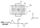
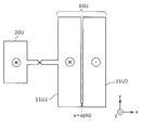
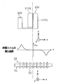
- FIG. 2 is a diagram illustrating an example of a relationship between the power generation coil and the magnetic field generation coil.
- the feeding coil 30 includes a core 31 and a winding 32.
- the x, y, and z directions in the figure are a three-dimensional orthogonal coordinate system.
- the horizontal plane of the feeding coil 30 is defined by the x direction and the y direction (xy plane), and the vertical direction (normal direction) orthogonal to the horizontal plane is defined as the z direction.
- the x direction is a direction along the central axis of the winding 32 of the feeding coil 30.
- Solenoid coils and spiral coils used as power transmission coils have places where the magnetic field in the z direction is zero.
- the magnetic field in the z direction becomes zero.
- the sensor coil substrate 140 and the sensor coil disposed thereon are disposed in parallel to the xy plane of the power feeding coil 30, the direction of magnetic flux passing through the sensor coil is the z direction. That is, the detection sensitivity of the foreign matter 160 decreases in a region where no z-direction magnetic flux exists.
- the magnetic field generating coil 10 that generates the magnetic flux in the z direction is provided so as to supplement the magnetic flux distribution in the z direction generated by the power supply coil 30.
- a magnetic flux in the z direction can be generated by passing a current through the magnetic field generating coil 10.
- the power generating coil 20 is provided as a power source for the magnetic field generating coil 10.
- the power generation coil 20 can generate electric power by electromagnetic induction by being arranged in a magnetic flux distribution of the power supply coil 30 at a place where a magnetic flux in the z direction exists.
- the power generating coil 20 is disposed not near the center of the feeding coil 30 in the x direction but near the boundary between the winding 31 and the end of the core 31 of the feeding coil 30 where the winding 32 is not wound. . In this vicinity, the magnetic flux density in the z direction is large and the power generation efficiency is good.
- the electric power generated by the power generation coil 20 is supplied as a part or all of the power source of the foreign object detection device 1.
- the present invention can be applied not only as a power source for a drive circuit of the magnetic field generating coil 10 but also as a power source for a gate driver, a power source for a microcomputer, a power source for a determination circuit, and power used for communication.
- the magnetic field generating coil 10, the power generating coil 20, and their connection can be realized with simple wiring, and no other electrical components are required in principle.
- the magnetic field generating coil 10, the power generating coil 20 and their connection can be arranged on the sensor coil substrate 140. For this reason, the size and weight of the non-contact power feeding device 100 are hardly increased compared to the case where the magnetic field generating coil 10 is separately provided, and can be realized at low cost.
- the magnetic coupling coefficient between the power supply coil 30 and the power generation coil 20 is greater than 10%, there may be a problem in power supply and demand from the power supply coil substrate 130 to the power reception coil substrate 150. Therefore, the magnetic coupling coefficient between the magnetic field generating coil 10 and the power feeding coil 30 is preferably 10% or less.
- the magnetic coupling coefficient between the magnetic field generating coil 10 and the power receiving coil is preferably 10% or less.
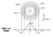
- FIG. 3 is a diagram illustrating an example of an arrangement relationship between the magnetic field generating coil and the feeding coil according to the embodiment.
- the lower part of FIG. 3 shows the magnetic field distribution in the z direction of the solenoid-type power feeding coil 30.
- the generated magnetic field in the central region in the x direction is zero.
- the detection sensitivity decreases in the central region in the x direction.
- the magnetic field generating coil 10 is disposed in the center region in the x direction of the feeding coil 30 in the upper part of FIG.
- the magnetic field generating coil 10 has a relatively small magnetic field component in the normal direction (z-axis direction) of the plane including the magnetic field generating coil 10 among the magnetic fields formed by the power feeding coil 30 and the power receiving coil, or Placed in a location that is zero.
- the foreign matter detection sensitivity in the central region in the x direction is improved, and foreign matter can be detected with high accuracy in the entire region on the feeding coil 30.
- the z-direction magnetic field is small in the area near the midpoint of the straight line connecting the coil center and the outermost circumference of the coil. Therefore, it is preferable to arrange the magnetic field generating coil in the area.
- the shape of the magnetic field generating coil that is suitable for the shape of each power transmission coil may be selected.
- the shape of the magnetic field generating coil suitable for the shape may be selected.
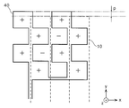
- FIG. 4A is a plan view showing an example of the shape of the magnetic field generating coil according to the embodiment.
- the magnetic field generating coil 10A shown in the figure is provided on the magnetic field generating coil substrate 110 shown in FIG. 1, and has a plurality of magnetic field generating coil units 11A.
- the magnetic field generating coil unit is a conductive wire that forms a closed loop (or a loop in which one part is discontinuous) as a minimum unit that generates a magnetic field in one direction when a current flows.
- the coordinates shown in FIG. 4A coincide with the coordinates in FIG. That is, the x direction in FIG. 4A coincides with the x direction of the feeding coil 30, and the y direction in FIG. 4A coincides with the y direction of the feeding coil 30.
- the number of magnetic field generating coils may be one.
- the EV (Electric Vehicle) application field since the size of the feeding coil is large, it is necessary to detect the foreign matter 160 in a wide area, and thus a plurality of magnetic field generating coil units are required.
- the plurality of magnetic field generating coil units 11A are arranged side by side at equal intervals in the x direction on the magnetic field generating coil substrate 110 shown in FIG.
- the magnetic field generating coil unit 11A has a vertically long shape in which the length c1 in the y direction is longer than the length a1 in the x direction and the interval b1 in the x direction.
- the vertically long magnetic field generating coil 10 ⁇ / b> A is suitable for combination with the solenoid-type power supply coil 30.
- each magnetic field generating coil unit 11A is all clockwise (clockwise). By making the current direction of the magnetic field generating coil unit 11A the same, the generated magnetic field can be strengthened.
- the width a1 and the interval b1 of the magnetic field generating coil unit 11A have the same length. Thereby, the downward magnetic field and the upward magnetic field have the same strength. Note that the width a1 and the interval b1 may be different.
- the shape of the magnetic field generating coil 10A preferably corresponds to the shape of the sensor coil of the sensor coil substrate 140.
- the magnetic field generating coil unit 11A preferably corresponds to the shape of one sensor coil or a plurality of sensor coils arranged continuously.
- the magnetic field generating coil is preferably square as in the magnetic field generating coil unit 11A of FIG. 4A.
- it is a hexagonal sensor coil what is necessary is just to match
- the magnetic field generating coil array when the magnetic field generating coil units are arranged side by side, the area that can be formed by the outer frame is called the magnetic field generating coil array, and when the sensor coils are arranged by side, the area that can be formed by the outer frame is the sensor coil array. I will call it.
- the size of the magnetic field generating coil array needs to be about the same as the size of the sensor coil array and about the same area as the region where the foreign material 160 can exist.
- the magnetic field generating coil array and the sensor coil array need to be arranged not only in size but also in position.
- the magnetic field generating coil unit 11A shown in FIG. 4A is a vertically long magnetic field generating coil, but it may have a horizontally long shape depending on the characteristics of the sensor coil. That is, depending on the interrelationship between the characteristics including the shape of the magnetic field generating coil, the characteristics including the shape of the sensor coil, the characteristics and location of the foreign matter that must be detected, and the characteristics of the magnetic field that exists outside the magnetic field generating coil. It is necessary to determine the shape and characteristics of the magnetic field generating coil unit and the sensor coil.
- FIG. 4B is a plan view showing the shape of the magnetic field generating coil according to the first modification of the embodiment.
- the magnetic field generating coil 10B shown in the figure has magnetic field generating coil units 11B1 and 11B2.
- the magnetic field generating coil unit 11B1 disposed in the central portion has a circular shape
- the magnetic field generating coil unit 11B2 disposed in the outer peripheral portion has a donut shape (annular shape).
- the number of magnetic field generating coil units is exemplified as two, but the number of magnetic field generating coil units may be three or more.
- a2 is the diameter of the magnetic field generating coil unit 11B1
- b2 is the distance between the magnetic field generating coil units 11B1 and 11B2
- c2 is the width of the magnetic field generating coil unit 11B2.
- a2, b2, and c2 may be the same or different, but preferably correspond to the shape of the sensor coil.
- the magnetic field generating coil 10B is suitable for combination with a spiral type feeding coil.
- the position of the wiring constituting the circumference of each magnetic field generating coil unit is made to coincide with the winding position of the spiral power feeding coil. Thereby, the foreign substance detection sensitivity improves.
- the magnetic field generating coil may have a variable area.
- the direction of the current flowing through the magnetic field generating coil may be fixed or variable.
- the plurality of magnetic field generating coil units may be electrically driven independently, or the plurality of magnetic field generating coil units may be driven by being connected in parallel, or may be driven by being connected in series. Also good.
- the plurality of magnetic field generating coil units may be formed electrically in series and continuously (in a one-stroke layout) as shown in the following modified examples 5A to 5C.
- FIG. 5A is a plan view showing the shape of the magnetic field generating coil according to the second modification of the embodiment.
- the magnetic field generating coil 10C shown in the figure has magnetic field generating coil units 11C1 and 11C2.
- the magnetic field generating coil 10C shown in FIG. 5A is an example in which the magnetic field generating coil 10A shown in FIG. 4A is formed electrically in series and continuously (by a one-stroke method).
- FIG. 5B is a plan view showing the shape of the magnetic field generating coil according to the third modification of the embodiment.
- the magnetic field generating coil 10D shown in the figure has magnetic field generating coil units 11D1 and 11D2.
- the magnetic field generating coil 10D shown in FIG. 5B is an example in which the magnetic field generating coil 10B shown in FIG. 4B is formed electrically in series and continuously (by a one-stroke method).
- FIG. 5C is a plan view showing the shape of the magnetic field generating coil according to the fourth modification of the embodiment.
- the magnetic field generating coil 10E shown in the figure has a plurality of magnetic field generating coil units 11E.
- the magnetic field generating coil 10E shown in FIG. 5C is an example in which small rectangular magnetic field generating coil units 11E are electrically connected in series and continuously (by a one-stroke method).
- the number of conductive wires forming the magnetic field generating coil is reduced to a minimum of one. It becomes possible to do. Thereby, it is not necessary to apply a voltage to each magnetic field generating coil unit, and a set of terminals for applying a predetermined potential difference (Vd1-Vd2) to the magnetic field generating coil can be made. Therefore, simplification of the drive circuit for driving the magnetic field generating coil can be realized, so that the cost can be reduced, the weight can be reduced, and the reliability can be improved by reducing the number of components.
- the directions of the magnetic fields in the regions divided by the magnetic field generating coil units are opposite to each other.
- the shape of the magnetic field generating coil unit formed electrically in series and continuously may be a triangle, square, pentagon, hexagon, circle, donut, or pizza shape, Moreover, the shape of these combinations may be sufficient.
- the magnetic field generating coil 10E shown in FIG. 5C is a one-stroke example in which a plurality of magnetic field generating coil units 11E are arranged also in the y direction, and is suitable for combination with a solenoid-type power feeding coil.
- the magnetic field generating coil may be formed by subdividing the donut-shaped magnetic field generating coil 10D of FIG.
- the shape of the magnetic field distribution can be controlled, and it becomes possible to cope with various foreign object detections.
- FIG. 6A is a plan view showing the shape of the magnetic field generating coil according to the fifth modification of the embodiment.
- the magnetic field generating coil 10F shown in the figure has magnetic field generating coil sets 12F1 and 12F2.
- the magnetic field generating coil set is a unit having one or more sets of voltage application terminals in which one or more magnetic field generating coil units are electrically connected in series and continuously (by a one-stroke method).
- the magnetic field generating coil set 12F1 has a plurality of magnetic field generating coil units 11F1
- the magnetic field generating coil set 12F2 has a plurality of magnetic field generating coil units 11F2.
- each of the magnetic field generating coil set 12F1 and the magnetic field generating coil set 12F2 has a comb shape formed of a plurality of magnetic field generating coil units.
- the comb-shaped magnetic field generating coil set 12F1 and the magnetic field generating coil set 12F2 are combined along the comb-shaped irregularities.
- the magnetic field generating coil 10F can arbitrarily adjust the direction of the magnetic field outside the magnetic field generating coil unit 11F1 or 11F2.
- the direction of the magnetic field in the magnetic field generating coil unit and the outside of the magnetic field generating coil unit are It is always opposite to the magnetic field direction.
- the plurality of magnetic field generating coil units 11F1 and the plurality of magnetic field generating coil units 11F2 are connected in series, but may be connected in parallel.
- the resistance of the wiring for connection needs to be smaller than the resistance of the wiring that forms the magnetic field generating coil unit. Thereby, the electric current which flows into each magnetic field generation coil unit becomes comparable.
- the resistance of the wiring connecting the magnetic field generating coil unit is not sufficiently small, the current of the magnetic field generating coil unit near the voltage application terminal is large, and the current of the magnetic field generation coil unit far from the voltage application terminal is small. For this reason, a uniform magnetic field cannot be generated in the magnetic field generating coil.
- FIG. 6B is a plan view showing the shape of the magnetic field generating coil according to the sixth modification of the embodiment.
- the magnetic field generating coil 10G shown in the figure has magnetic field generating coil sets 12G1, 12G2, and 12G3.
- the magnetic field generating coil sets 12G1, 12G2, and 12G3 have different areas in the coils. According to this configuration, if the current direction of each magnetic field generating coil set is the same, the magnetic field at the center can be maximized.
- connection of each magnetic field generating coil set may be connected in series or in parallel.
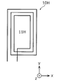
- FIG. 7A is a plan view showing the shape of a magnetic field generating coil according to Modification 7 of the embodiment.
- the magnetic field generating coil 10H shown in the figure has one magnetic field generating coil unit 11H.
- the magnetic field generating coil unit 11H is wound a plurality of times. According to this configuration, the magnetic field at the center can be maximized.
- FIG. 7B is a plan view showing the shape of the magnetic field generating coil according to the modified example 8 of the embodiment.
- the magnetic field generating coil 10J shown in the figure has a magnetic field generating coil set composed of parallel connections 13J1 and 13J2, four magnetic field generating coil unit wires 13J3, and four magnetic field generating coil unit wires 13J4. Yes.
- a current in the y-axis positive direction is passed through the four magnetic field generating coil unit wires 13J3, and a current in the y-axis negative direction is passed through the four magnetic field generating coil unit wires 13J4. This makes it possible to maximize the magnetic field in the central region.
- the magnetic field generating coil 10J can be regarded as a modification of the magnetic field generating coil 10G in FIG. 6B.
- the resistance of the parallel connections 13J1 and 13J2 needs to be smaller than the resistance of the magnetic field generating coil unit wires 13J3 and 13J4. Thereby, the electric current which flows into each magnetic field generation coil unit line becomes comparable.
- the resistances of the parallel connections 13J1 and 13J2 are not sufficiently small, the current of the magnetic field generating coil unit line close to the voltage application terminal is large, and the current of the magnetic field generating coil unit line far from the voltage application terminal is small. For this reason, a uniform magnetic field cannot be generated in the magnetic field generating coil.
- the positions of the sides forming the magnetic field generating coil unit are arranged to coincide with the positions of the sides of the sensor coil unit.
- the sensor coil unit is a conductive wire that forms a closed loop (or a loop in which one part is discontinuous) as a minimum unit for detecting a change in magnetic flux.
- the amount of magnetic field as a vector amount is reduced by the reverse magnetic flux line passing through one sensor coil unit. For this reason, the foreign object detection sensitivity is lowered. From this point of view, by matching the sides of the magnetic field generating coil unit and the sensor coil unit, the amount of magnetic flux passing through the sensor coil unit can be maximized, and the foreign matter detection sensitivity can be improved. .
- one or a plurality of sensor coil units be included in the magnetic field generating coil unit.
- the size of the magnetic field generating coil unit affects the shape of the magnetic field distribution that it generates.
- the foreign object detection sensitivity is greatly influenced by the location and size of the foreign object 160. Therefore, it is preferable that the optimum size and shape of the unit magnetic field generating coil be determined by the foreign matter 160 to be detected and the conditions of the location.
- the size and shape of the sensor coil unit be similarly determined by the foreign matter 160 to be detected and the location of the foreign object 160. From this point of view, the sizes and shapes of the magnetic field generating coil unit and the sensor coil unit do not always match. Further, the size and shape of one of the magnetic field generating coil unit and the sensor coil unit affect the optimum size and shape of the other. It is preferable to optimize both in this relationship.
- the width of the sensor coil unit (length of the side) and the width of the magnetic field generating coil unit (side
- the width of the sensor coil unit should be long, and when detecting a small foreign object, the width of the sensor coil unit should be short.
- the sensor coil unit should be wider than the magnetic field generating coil unit. Will be better.
- the sensor coil unit may be arranged so that one or a plurality of times the magnetic field generating coil unit can enter, and the sides of the sensor coil unit coincide with each other.
- the above relationship between the side forming the sensor coil unit and the side forming the magnetic field generating coil unit is a condition applicable to any shape of sensor coil unit.
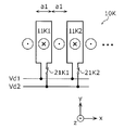
- FIG. 8A is a plan view showing the shape of the magnetic field generating coil according to the ninth modification of the embodiment.
- the magnetic field generating coil 10K shown in the figure includes a plurality of magnetic field generating coil units 11K1 and 11K2, a voltage applying terminal for supplying current to the plurality of magnetic field generating coil units, a magnetic field generating coil unit 11K1 and a voltage applying terminal. And a switch 21K2 provided between the magnetic field generating coil unit 11K2 and the voltage application terminal.
- the switch 21K1 is a first switch element that selects whether or not to supply current to the magnetic field generating coil unit 11K1.
- the switch 21K2 is a first switch element that selects whether or not to supply current to the magnetic field generating coil unit 11K2.
- the figure shows a configuration in which switches 21K1 and 21K2 are connected to a plurality of rectangular magnetic field generating coil units 11K1 and 11K2, respectively, and a magnetic field generating coil unit to be driven can be selected by turning on and off the switches. ing. Vd1 and Vd2 are applied to the voltage application terminals of the magnetic field generating coil unit. For example, the drive circuit executes the on / off switching of the switches 21K1 and 21K2.
- the currents flowing through the selected magnetic field generating coil units are in the same direction, but may be in different directions.
- the interval between the wirings for applying Vd1 and Vd2 is arbitrary, but when the magnetic field generated by the wirings adversely affects other devices, it is preferable to shorten the interval between the wirings as much as possible.
- the other devices mentioned here are a sensor coil, a power transmission coil, an electric circuit, an electronic circuit, and the like.
- FIG. 8B is a plan view showing the shape of the magnetic field generating coil according to Modification 10 of the embodiment.
- the magnetic field generating coil 10L shown in the figure is an example in which the concept of the magnetic field generating coil 10K shown in FIG. 8A is embodied by a circular and donut-shaped magnetic field generating coil unit.
- switches 21L1 and 21L2 are connected to a circular magnetic field generating coil unit 11L1 and a donut-shaped magnetic field generating coil unit 11L2, respectively.
- the switches 21L1 and 21L2 are switched on and off, for example, by a drive circuit.
- FIG. 9A is a plan view showing the shape of the magnetic field generating coil according to the eleventh modification of the embodiment.
- the magnetic field generating coil 10M shown in the figure is an example in which the number of selected magnetic field generating coil units and the area of the magnetic field generating coil unit are made variable.
- the switches 21M1 and 21M2 are arranged on a plurality of coil unit wires. By turning on and off the switches 21M1 and 21M2, the current of the coil unit wiring constituting the magnetic field generating coil unit can be controlled.
- the magnetic field direction shown in FIG. 9A is an example when Vd1> Vd2, the switch 21M1 is turned on, and the switch 21M2 is turned off.
- FIG. 9B is a plan view showing the shape of the magnetic field generating coil according to the modified example 12 of the embodiment.
- the magnetic field generating coil 10N shown in the figure is an example in which the concept of the magnetic field generating coil 10M shown in FIG. 9A is embodied by a circular and donut-shaped magnetic field generating coil unit.
- the switches 21N1 and 21N2 are arranged on the plurality of coil unit wires. By turning on and off the switches 21N1 and 21N2, the current of the coil unit wiring constituting the magnetic field generating coil unit can be controlled.
- the magnetic field direction shown in FIG. 9B is an example when Vd1> Vd2, the switch 21N1 is turned on, and the switch 21N2 is turned off.
- the magnetic field direction of the magnetic field generating coil, the magnitude of the magnetic field, the number of the magnetic field generating coil units, and their location dependence can be changed by switching the switch on and off.
- the distribution of the magnetic field generated by the magnetic field generating coil can be changed.
- the foreign substance detection sensitivity which depends on the foreign substance which has a different characteristic and magnitude
- the place where a foreign substance exists is a place in a three-dimensional space including x, y, and z directions.
- the direction and magnitude of the current of the magnetic field generating coil can be changed according to the relationship between the magnitudes of the voltages Vd1 and Vd2.
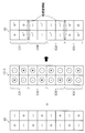
- FIG. 10A is a plan view showing the shape of the magnetic field generating coil according to the modification 13 of the embodiment.
- the magnetic field generating coil 10P shown in the figure includes magnetic field generating coil unit wires 13P1 and 13P2, voltage applying terminals for supplying current to the magnetic field generating coil unit wires 13P1 and 13P2, and switches 21P1H, 21P1L, 21P2H, 21P2L. , 21P3H, 21P3L, 21P4H, and 21P4L.
- the switches 21P1H, 21P1L, 21P2H, 21P2L, 21P3H, 21P3L, 21P4H, and 21P4L are provided between the magnetic field generating coil unit line and the voltage application terminal, and change the direction of the current flowing through the magnetic field generating coil unit lines 13P1 and 13P2. This is the second switch element.
- Magnetic field generating coil unit wires 13P1 and 13P2 are wires constituting the coil unit.
- One end of the magnetic field generating coil unit line 13P1 is connected to a power supply line to which Vd1 is applied via a switch 21P1H, and is connected to a power supply line to which Vd2 is applied via a switch 21P1L.
- the other end of the magnetic field generating coil unit line 13P1 is connected to a power supply line that applies Vd1 via a switch 21P2H, and is connected to a power supply line that applies Vd2 via a switch 21P2L.
- One end of the magnetic field generating coil unit line 13P2 is connected to a power supply line to which Vd1 is applied via a switch 21P3H, and is connected to a power supply line to which Vd2 is applied via a switch 21P3L.
- the other end of the magnetic field generating coil unit line 13P2 is connected to a power supply line to which Vd1 is applied via a switch 21P4H, and is connected to a power supply line to which Vd2 is applied via a switch 21P4L.
- the magnetic field generating coil 10P is configured so that Vd1 or Vd2 is selectively applied to each voltage application terminal by providing two switches for each of the two voltage application terminals of the magnetic field generation coil unit line. In this configuration example, the voltage can be opened without being applied.
- Vd1 and Vd2 Application of Vd1 and Vd2 to the magnetic field generating coil unit line is executed by a drive circuit for driving the magnetic field generating coil.
- Vd1 and Vd2 are different voltages, and the potential difference is applied to the magnetic field generating coil.
- one or a plurality of magnetic field generating coil units can be formed by applying Vd1 or Vd2 to both ends of the magnetic field generating coil unit wires 13P1 and 13P2.
- the drive circuit When generating a magnetic field in the magnetic field generating coil 10P, the drive circuit turns on and off each switch so that a current flows through the magnetic field generating coil unit line.
- Vd2 is applied to one end (upper side in the figure) of the magnetic field generating coil unit line 13P1 by turning off the switch 21P1H and turning on the switch 21P1L.
- Vd1 is applied to the other end (lower side in the drawing) of the magnetic field generating coil unit line 13P1 by turning on the switch 21P2H and turning off the switch 21P2L.
- Vd1> Vd2 the current flowing through the magnetic field generating coil unit wire 13P1 is upward (y-axis positive direction).
- Vd1 is applied to one end (upper side in the figure) of the magnetic field generating coil unit line 13P2 by turning on the switch 21P3H and turning off the switch 21P3L.
- Vd2 is applied to the other end (lower side in the figure) of the magnetic field generating coil unit line 13P2 by turning off the switch 21P4H and turning on the switch 21P4L.
- Vd1> Vd2 the current flowing through the magnetic field generating coil unit line 13P2 is downward (y-axis negative direction).
- the current flowing through the magnetic field generating coil unit line 13P1 is directed downward (in the negative y-axis direction).
- the current flowing through the magnetic field generating coil unit line 13P2 is upward (y-axis positive direction). Due to the current flow of the magnetic field generating coil unit wires 13P1 and 13P2, the magnetic field direction is upward (z-axis positive direction) in the region sandwiched between the magnetic field generating coil unit wires 13P1 and 13P2.
- the magnetic field direction can be reversed by controlling the on / off of the switch.
- switch 21P1H and the switch 21P1L are not turned on at the same time in order to avoid an output short circuit of the drive circuit. Further, the switch 21P2H and the switch 21P2L are not turned on at the same time. Further, the switch 21P3H and the switch 21P3L are not turned on at the same time. Further, the switch 21P4H and the switch 21P4L are not turned on at the same time.
- the switch 21P1H and the switch 21P1L may be turned off simultaneously. Thereby, one end (upper side in the figure) of the magnetic field generating coil unit wire 13P1 is opened. Further, for example, the switch 21P2H and the switch 21P2L may be turned off simultaneously. Thereby, the other end (lower side in the figure) of the magnetic field generating coil unit wire 13P1 is opened. In this way, by setting one end, the other end, or both ends of the magnetic field generating coil unit wire 13P1 in an open state, it is possible to prevent current from flowing through the magnetic field generating coil unit wire 13P1.
- the switch may be a semiconductor electronic device, a relay, or a mechanical type.
- Semiconductor electronic device switches include MOSFETs (Metal-Oxide-Semiconductor Field-Effect Transistor), IGBTs (Insulated Gate Bipolar Transistors), and BJTs (Bipolar Junction Transistors).
- Examples of the material for the semiconductor electronic device include Si, SiC, and GaN.
- the switch according to this modification preferably has a high breakdown voltage and a low on-resistance for reducing loss. From this viewpoint, IGBT or BJT is desirable, and one using SiC material is desirable.
- the drive circuit may independently control on / off of the switches connected to the magnetic field generating coil unit lines 13P1 and 13P2, or may be controlled in association with each other.
- the magnetic field generating coil 10P is an embodiment in which a rectangular magnetic field generating coil unit is modified, and is suitable for combination with a solenoid type power feeding coil.
- FIG. 10B is a plan view showing the shape of the magnetic field generating coil according to the modified example 14 of the embodiment.
- the magnetic field generating coil 10Q shown in the figure has circular magnetic field generating coil unit wires 13Q1 and 13Q2, and switches 21Q1H, 21Q1L, 21Q2H, 21Q2L, 21Q3H, 21Q3L, 21Q4H, and 21Q4L.
- the magnetic field generating coil 10Q is an example in which the magnetic field generating coil 10P is modified into a circular and donut-shaped magnetic field generating coil.
- the same points as the configuration of the magnetic field generating coil 10P will not be described, and different points will be mainly described.
- Magnetic field generating coil unit wires 13Q1 and 13Q2 are wires constituting the coil unit.
- One end of the magnetic field generating coil unit line 13Q1 is connected to a power supply line to which Vd1 is applied via a switch 21Q1H, and is connected to a power supply line to which Vd2 is applied via a switch 21Q1L.
- the other end of the magnetic field generating coil unit line 13Q1 is connected to a power supply line to which Vd1 is applied via a switch 21Q2H, and is connected to a power supply line to which Vd2 is applied via a switch 21Q2L.
- One end of the magnetic field generating coil unit line 13Q2 is connected to a power supply line to which Vd1 is applied via a switch 21Q3H, and is connected to a power supply line to which Vd2 is applied via a switch 21Q3L.
- the other end of the magnetic field generating coil unit line 13Q2 is connected to a power supply line to which Vd1 is applied via a switch 21Q4H, and is connected to a power supply line to which Vd2 is applied via a switch 21Q4L.
- the magnetic field generating coil 10Q is configured so that Vd1 or Vd2 is selectively applied to each voltage application terminal by providing two switches for each of the two voltage application terminals of the magnetic field generation coil unit line. In this configuration example, the voltage can be opened without being applied.
- Vd1 and Vd2 Application of Vd1 and Vd2 to the magnetic field generating coil unit line is executed by a drive circuit for driving the magnetic field generating coil.
- Vd1 and Vd2 are different voltages, and the potential difference is applied to the magnetic field generating coil.
- one or a plurality of magnetic field generating coil units can be formed by applying Vd1 or Vd2 to both ends of the magnetic field generating coil unit wires 13P1 and 13P2.
- the switches are connected to both ends of the circular magnetic field generating coil unit wires 13Q1 and 13Q2.
- the magnetic field generating coil unit wires are divided into two semicircles and divided into semicircles.
- the switch may be connected to both ends of the magnetic field generating coil unit wire.
- the circular magnetic field generating coil unit wire may be divided into three or more.
- the magnetic field generating coil 10Q is an embodiment in which a circular and donut-shaped magnetic field generating coil unit is modified, and is suitable for combination with a spiral type feeding coil.
- a method of selecting a magnetic field generating coil unit line like the magnetic field generating coils 10P and 10Q is referred to as a magnetic field generating coil unit line selecting method.
- the power consumption of the drive circuit that drives the magnetic field generating coil depends on the output current, and the loss increases as the output current increases. On the other hand, when the current flowing through the magnetic field generating coil is increased, the generated magnetic field can be increased, and the foreign matter detection sensitivity is improved.
- the thickness of the casing is about 1 cm.
- the distance from the sensor coil to the foreign matter is about 1 cm. The longer this distance, the lower the detection sensitivity because the magnetic field at the location of the foreign object decreases. Therefore, a larger magnetic field is required in order to detect foreign matter with high accuracy.
- the power transmission coil in EV application has a large electric power and therefore a large current, the magnetic field generated by the power transmission coil becomes large. Since the heat generation of the foreign matter is determined by the magnetic field of the power transmission coil, the heat generation of the foreign matter becomes large. From this viewpoint, in the EV application field, it is necessary to detect a smaller foreign object, and it is necessary to detect a foreign object at a farther place.
- the modified examples 13 and 14 allow the selection of the magnetic field generating coil unit wire constituting the magnetic field generating coil unit.
- a large current is required to drive all the unit magnetic field generating coils at the same time, which increases the loss. Further, if the magnetic field generating coil units are connected in series, a large voltage is required even with the same current, and it is necessary to increase the loss and at the same time have a high breakdown voltage.
- the magnetic field generating coil unit wire selection method described above it is possible to perform a single foreign object detection operation by generating a magnetic field in a narrow range, move a place, and perform foreign object detection multiple times. Become. As a result, it is possible to detect foreign matter with high accuracy without increasing loss and without reducing detection sensitivity.
- the magnetic field generating coil 10M in FIG. 9A and the magnetic field generating coil 10N in FIG. 9B described above have some characteristics of the magnetic field generating coil unit line selection method. However, in the magnetic field generating coils 10M and 10N, when the potential difference between Vd1 and Vd2 is constant, the current direction of the coil unit wiring is constant, and the current direction cannot be varied like the magnetic field generating coils 10P and 10Q. .
- the magnetic field generating coils 10P and 10Q each have a configuration in which there are two magnetic field generating coil unit wires.
- the present invention is not limited to this, and there are three magnetic field generating coil unit wires depending on the required magnetic field generating range. It may be the above.
- a plurality of magnetic field generating coil unit wires may be arranged side by side and connected in parallel. Thereby, the current flowing through one magnetic field generating coil unit line can be reduced, and the heat generation temperature can be reduced. Furthermore, by arranging a plurality of magnetic field generating coil unit wires so as to be adjacent to each other, the generated magnetic field can be increased, and as a result, the foreign matter detection sensitivity is improved.
- FIG. 10C is a plan view showing the shape of the magnetic field generating coil according to the modification 15 of the embodiment.
- the magnetic field generating coil 10R shown in the figure is an embodiment modified to eliminate the switch on the upper side (y-axis positive direction) of the magnetic field generating coil 10P.
- the magnetic field generating coil 10R includes magnetic field generating coil unit wires 13R1 and 13R2, and switches 21R1H, 21R1L, 21R2H, and 21R2L.
- Magnetic field generating coil unit wires 13R1 and 13R2 are wires constituting the coil unit. One end of the magnetic field generating coil unit wire 13R1 and one end of the magnetic field generating coil unit wire 13R2 are connected via a common wiring. The other end of the magnetic field generating coil unit line 13R1 is connected to a power supply line to which Vd1 is applied via a switch 21R1H, and is connected to a power supply line to which Vd2 is applied via a switch 21R1L. The other end of the magnetic field generating coil unit line 13R2 is connected to a power supply line to which Vd1 is applied via a switch 21R2H, and is connected to a power supply line to which Vd2 is applied via a switch 21R2L.
- the magnetic field generating coil 10P can make the current flowing through all the selected magnetic field generating coil unit lines the same direction, while the magnetic field generating coil 10R has the current direction of the selected magnetic field generating coil unit line being , Both orientations are set to exist.
- the number of selected magnetic field generating coil unit lines must be two or more.
- the number of switches of the magnetic field generating coil 10R may be half that of the magnetic field generating coil 10P, the cost can be reduced and the size can be reduced.
- FIG. 10D is a plan view showing the shape of the magnetic field generating coil according to the modification 16 of the embodiment.
- the magnetic field generating coil 10S shown in the figure is an embodiment modified to eliminate the switch on the left side (x-axis negative direction) of the magnetic field generating coil 10S.
- the magnetic field generating coil 10S has circular magnetic field generating coil unit wires 13S1 and 13S2, and switches 21S1H, 21S1L, 21S2H, and 21S2L.
- Magnetic field generating coil unit wires 13S1 and 13S2 are wires constituting the coil unit. One end of the magnetic field generating coil unit line 13S1 and one end of the magnetic field generating coil unit line 13S2 are connected via a common wiring. The other end of the magnetic field generating coil unit line 13S1 is connected to a power supply line to which Vd1 is applied via a switch 21S1H, and is connected to a power supply line to which Vd2 is applied via a switch 21S1L. The other end of the magnetic field generating coil unit line 13S2 is connected to a power supply line to which Vd1 is applied via a switch 21S2H, and is connected to a power supply line to which Vd2 is applied via a switch 21S2L.
- the magnetic field generating coil 10Q can make the currents flowing through all the selected magnetic field generating coil unit lines the same direction, while the magnetic field generating coil 10S has the current direction of the selected magnetic field generating coil unit lines being , Both orientations are set to exist.
- the number of selected magnetic field generating coil unit wires must be two or more.
- the number of switches of the magnetic field generating coil 10S may be half that of the magnetic field generating coil 10Q, the cost can be reduced and the size can be reduced.
- FIG. 11A is a diagram showing the positional relationship between the magnetic field generating coil and the foreign matter
- FIG. 11B is a graph showing the relationship between the magnetic field generating coil-foreign matter distance and the width of the magnetic field generating coil unit.
- FIG. 11A shows an arrangement relationship between a magnetic field generating coil substrate 110 on which a typical magnetic field generating coil 10 is mounted and a sensor coil substrate 140 on which a foreign object 160 exists.
- the distance between the magnetic field generating coil substrate 110 and the foreign material 160 is d.
- the foreign material 160 is attached on the surface of the housing that covers the sensor coil substrate 140.
- the width in the x direction of the magnetic field generating coil unit 11A constituting the magnetic field generating coil 10 is assumed to be a.
- FIG. 11B shows the relationship between the distance d and the optimum width a of the magnetic field generating coil unit.
- the magnitude of the z-direction magnetic field generated by the magnetic field generating coil 10 decreases with increasing distance from the magnetic field generating coil 10 in the z direction.
- the magnetic field in the z direction depends on the width a of the magnetic field generating coil unit, and there is an optimum width aopt that maximizes the z direction magnetic field when the width a is changed at a certain distance d.
- the design value of the width a of the magnetic field generating coil unit is preferably (2.0 ⁇ 0.5) ⁇ d.
- the width of the magnetic field generating coil unit which is the length of the short side of the rectangle or the width of the ring, is not less than 1.5 times and not more than 2.5 times the distance between the plane including the magnetic field generating coil unit and the foreign matter. It is preferable.
- the foreign object detection device 1 has a drive circuit that drives a magnetic field generating coil.
- the drive circuit applies voltages (Vd1 and Vd2) and a current to the magnetic field generating coil.
- the current and voltage waveforms applied by the drive circuit are a sine wave, a triangular wave, a rectangular wave, a pulse wave, and the like.
- the foreign substance detection sensitivity improves as the electromotive force of the sensor coil unit increases.
- the electromotive force V of the sensor coil unit is proportional to the time change of the magnetic flux ⁇ penetrating the sensor coil unit. Therefore, the foreign substance detection sensitivity is improved as the absolute value of the temporal change amount of the magnetic flux ⁇ is larger. Therefore, if the absolute value of the time change amount of the current flowing through the magnetic field generating coil is increased, the foreign matter detection sensitivity is improved. That is, the foreign object detection sensitivity is improved by increasing the absolute value of the time change amount of the current supplied from the drive circuit to the magnetic field generating coil.
- the drive circuit drives the magnetic field generating coil by changing at least one of an absolute value and a temporal change amount of current, voltage, power and frequency supplied to the magnetic field generating coil unit.
- the drive circuit preferably drives the magnetic field generating coil such that the time differential value of the current flowing through the magnetic field generating coil unit is 1 A / 50 ns or more.
- the electromotive force generated by the power generation coil 20 drives the magnetic field generation coil. That is, the drive circuit may include the power generation coil 20. Moreover, you may use the electromotive force which the power generation coil 20 produced
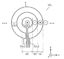
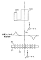
- FIG. 12 is a plan view showing the shapes of the magnetic field generating coil and the power generating coil according to the modified example 17 of the embodiment.
- the figure shows a doughnut-shaped magnetic field generating coil 10T and a circular power generating coil 20T when the power transmission coil is a spiral coil.
- the magnetic field generating coil 10T and the power generating coil 20T are mounted on the magnetic field generating coil substrate 110, for example. That is, the magnetic field generation coil substrate 110 further includes a power generation coil 20T that generates an electromotive force using a magnetic field generated by the power feeding coil and the power reception coil and supplies the generated electromotive force to the magnetic field generation coil unit.
- the power generation coil 20T is disposed at the center. Further, the magnetic field generating coil 10T is disposed in the outer peripheral region of the power feeding coil having a small z-direction magnetic field.
- the power generating coil 20T and the magnetic field generating coil 10T are coupled by wiring. In realizing the above configuration, as shown in FIG. 12, the power generating coil 20 ⁇ / b> T and the magnetic field generating coil 10 ⁇ / b> T can be configured by a single stroke writing method on one plane.
- the intermittent operation of magnetic field generation by the time division method can reduce both power consumption and electromagnetic radiation.
- the intermittent operation timing is synchronized with the intermittent operation timing of the detection circuit.
- the generated voltage of the generating coil 20T needs to be larger than the generated voltage of the magnetic field generating coil 10T.
- the current flowing through the power generation coil 20T and the magnetic field generation coil 10T is determined by the combined voltage of the power generation voltages and the resistance of the wiring layout.
- FIG. 2 shows a configuration example of the power generating coil 20 and the magnetic field generating coil 10 when the power transmission coil is a solenoid type power feeding coil.
- FIG. 12 shows a configuration example of the power generation coil 20T and the magnetic field generation coil 10T in the case where the power transmission coil is a spiral power supply coil.
- the magnetic field generated by the power transmission coil and the magnetic field generated by the magnetic field generation coil when the magnetic field generation coil is arranged in a region where the z-direction magnetic field generated by the power transmission coil is near zero are combined.
- a synthetic magnetic field to be created will be described.
- the region where the magnetic field in the z direction is near zero is the central region in the x direction in the case of a solenoid type power supply coil, and in the straight line connecting the coil center and the outermost periphery of the coil in the case of a spiral type power supply coil. This is the area near the point.
- the winding is circular
- the x coordinate at which the z-direction magnetic field becomes zero is set to xzh0 as in the case of the solenoid coil. xzh0 exists in one place in the plus region of x and one place in the minus region.
- + xzh0 and -xzh0 exist in a region separated by the same distance from the coil center. Since the spiral feeding coil is circular, it means that the z-direction magnetic field becomes zero in a region where a circle with a radius xzh0 is drawn on the xy plane. Further, the magnetic field in the region of ⁇ xzh0 ⁇ x ⁇ + xzh0 is opposite to the magnetic field of x ⁇ xzh0 and x> xzh0.
- the time change of the current flowing through the power generation coil reaches the peak value when the voltage generated by the power generation coil reaches the peak value.
- the time when the voltage of the power generation coil reaches the peak value is when the time variation of the magnetic field of the power transmission coil reaches the peak value. At this time, the current of the power transmission coil becomes almost zero.
- the time variation of the magnetic field of the magnetic field generating coil becomes a peak value when the current of the feeding coil becomes zero.
- the magnetic field generating coil becomes a combined magnetic field of the magnetic fields generated by the currents of the feeding coil and the receiving coil, and thus the time variation of the magnetic field of the magnetic field generating coil peaks. May deviate slightly from the time when the current of the power transmission coil becomes zero.
- the z-direction magnetic field of the power transmission coil and the magnetic field generating coil If the direction of the z-direction magnetic field is the same, the z-direction magnetic field intensifies in this region, and the foreign matter detection sensitivity is improved.
- the directions of both magnetic fields are opposite to each other, so that the z-direction magnetic field is weakened. That is, the foreign object detection sensitivity deteriorates in this region.
- FIG. 13A is a plan view showing shapes of a magnetic field generating coil and a power generating coil according to a modified example 18 of the embodiment.
- the figure shows the configuration of a magnetic field generating coil 10U and a power generating coil 20U corresponding to a solenoid-type power transmission coil.
- the magnetic field generating coil 10U has two magnetic field generating coil units 11U1 and 11U2 in which the directions of the generated magnetic fields are reversed.
- a part of the conductive wire forming the magnetic field generating coil units 11U1 and 11U2 is arranged at a place where the magnetic field component in the z-axis direction becomes 0 out of the magnetic field formed by the power feeding coil and the power receiving coil.
- the z-direction magnetic field direction of the power transmission coil and the magnetic field generation coil direction can be made the same in both areas, so that the z-direction magnetic field can be strengthened in both areas. Detection sensitivity is improved.
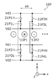
- FIG. 13B is a plan view showing the shapes of the magnetic field generating coil and the power generating coil according to the modified example 19 of the embodiment.
- the figure shows the configuration of a magnetic field generating coil 10V and a power generating coil 20V corresponding to a spiral type power transmission coil.
- the magnetic field generating coil 10V has two magnetic field generating coil units 11V1 and 11V2 in which the directions of the generated magnetic fields are reversed.
- the magnetic field generating coil unit 11V1 is arranged at x ⁇ xzh0
- the magnetic field generating coil unit 11V2 is arranged at x> xzh0.
- a part of the conductive wire forming the magnetic field generating coil units 11V1 and 11V2 is disposed at a place where the magnetic field component in the z-axis direction becomes 0 out of the magnetic field formed by the power feeding coil and the power receiving coil.
- the z-direction magnetic field direction of the power transmission coil and the magnetic field generation coil direction can be made the same in both areas, so that the z-direction magnetic field can be strengthened in both areas. Detection sensitivity is improved.
- the magnetic field generating coil and the power generating coil are formed electrically continuously (with a one-stroke layout), but this is not restrictive.
- the number of turns of each magnetic field generating coil unit may be plural. The number of turns may be changed depending on the strength of the magnetic field in the z direction. For example, if the number of turns is increased as the z-direction magnetic field is weaker, the z-direction magnetic field is leveled.
- the foreign substance detection sensitivity improves.
- the magnetic field change amount generated by the magnetic field generating coil and the magnetic field change amount generated by the power transmission coil are strengthened. Therefore, the foreign matter detection sensitivity is improved.
- a magnetic field generated by the magnetic field generating coil is also generated outside the magnetic field generating coil.
- the direction of the z-direction magnetic field of the left magnetic field generating coil unit 11U1 is opposite to the direction of the z-direction magnetic field on the left outside.
- the z-direction direction of the right magnetic field generating coil unit 11U2 is opposite to the z-direction magnetic field direction outside the right side.
- the direction of the z-direction magnetic field of the inner magnetic field generating coil unit 11V1 is opposite to the direction of the z-direction magnetic field in the region on the circle center side of the magnetic field generating coil unit 11V1.
- the direction of the z-direction magnetic field of the outer magnetic field generation coil unit 11V2 is opposite to the direction of the z-direction magnetic field in the region on the outer peripheral side of the magnetic field generation coil unit 11V2.
- the direction of the current of the magnetic field generating coil may be reversed, and foreign matter detection may be performed according to the current conditions of each direction.
- a current may be switched by providing a switch between the power generation coil and the magnetic field generating coil and turning the switch on and off.
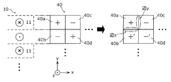
- FIG. 14A is a plan view showing the shapes of the magnetic field generating coil and the power generating coil according to Modification 20 of the embodiment. This figure shows the positional relationship between the magnetic field generating coil 10W1 connected to the power generating coil 20W1 and the magnetic field generating coil 10W2 connected to the power generating coil 20W2, and the power generating coil and the magnetic field generating coil are arranged on the same substrate. An example of the structure when formed is shown.
- the configuration example shown in FIG. 14A is suitable when the power transmission coil is a solenoid type coil, and is a configuration example in the case where power generation is performed by a power generation coil using the magnetic field of the solenoid type coil.
- the configuration of FIG. 14A is a configuration in which two sets of one power generating coil and one magnetic field generating coil are provided to detect foreign matter.
- the power generating coil 20W1 is arranged on the left side of the solenoid coil
- the magnetic field generating coil 10W1 is arranged on the right side of the central part so as to be in contact with the central part of the solenoid coil.
- the power generation coil 20W2 is disposed on the right side of the solenoid coil
- the magnetic field generating coil 10W2 is disposed on the left side of the center portion so as to contact the center portion of the solenoid coil.
- the two magnetic field generating coils 10W1 and 10W2 are adjacent to each other, and the boundary line between them is the central portion of the solenoid coil, and the z-direction magnetic field on the boundary line is zero or a region close to zero. It should be noted that the two magnetic field generating coils 10W1 and 10W2 need to be large enough to cover a region where the foreign matter detection sensitivity is low because the z-direction magnetic field of the solenoid coil is small.
- the configuration of FIG. 14A is suitable when the main component of the impedance of the magnetic field generating coil is an inductance component.
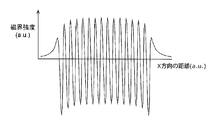
- the 14A shows the distribution of the magnetic field in the z direction of the solenoid coil.
- the directions of the z-direction magnetic fields in the left half and the right half are opposite. From the principle of electromagnetic induction, the phase of the current flowing through the magnetic field generating coil is determined by the electromotive force generated by the power generating coil 20W1 arranged on the left side. The direction of the magnetic field by this current matches the phase of the magnetic field on the right side of the solenoid coil. Therefore, when the power generation coil 20W1 is arranged on the left side, the magnetic field generating coil 10W1 connected to the power generation coil 20W1 is preferably arranged on the right side.
- the z-direction magnetic field can be increased by two scalar sums of the z-direction magnetic field generated by the solenoid coil and the z-direction magnetic field generated by the magnetic field generation coil. Therefore, it is possible to improve the foreign matter detection sensitivity.
- the magnetic field generating coil 10W2 connected thereto is preferably arranged on the left side from the same principle. As a result, the direction of the magnetic field of the magnetic field generating coil 10W2 is the same as the direction of the magnetic field of the solenoid coil in the region where it is disposed.
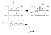
- FIG. 14B is a plan view showing the shapes of the magnetic field generating coil and the power generating coil according to the modified example 21 of the embodiment.
- the figure shows a magnetic field generating coil 10X connected to the power generating coil 20X, and shows a configuration example when the power generating coil and the magnetic field generating coil are formed on the same substrate.
- the phase difference between the magnetic field generating coil magnetic field and the solenoid coil magnetic field is ⁇ / 2
- only one magnetic field generating coil 10X is required. What is necessary is just to arrange
- FIG. 14A there are two sets of power generation coils and magnetic field generation coils, and in the configuration of FIG. 14B, there is one set of power generation coils and magnetic field generation coils. Therefore, the configuration of FIG. 14B has a smaller number of sets and better area efficiency. That is, when the main component of the impedance of the magnetic field generating coil is a resistance component, the configuration of FIG. 14B is more desirable.
- the resistance component of the magnetic field generating coil is preferably an inductance component, and from this viewpoint, the configuration in FIG. 14A is more preferable than the configuration in FIG. 14B.
- the configuration of FIG. 14A is more preferable. This is because the magnitude of the combined magnetic field of the z-direction magnetic field of each magnetic field generating coil and the z-direction magnetic field of the solenoid coil is the same in the configuration of FIG. 14A. If the configuration shown in FIG. 14B is used, the magnitude of the combined magnetic field differs between the right side and the left side of the magnetic field generating coil, which causes a difference in the foreign matter detection sensitivity and the sensitivity cannot be leveled. .
- the number of turns of the power generating coil may be plural, and the number of turns of the magnetic field generating coil may be plural.
- FIG. 14C is a plan view showing shapes of the magnetic field generating coil and the power generating coil according to the modified example 22 of the embodiment.
- the figure shows a magnetic field generation coil 10Y connected to the power generation coil 20Y, and shows a configuration example when the power generation coil and the magnetic field generation coil are formed on the same substrate.
- 14C is an example in which FIG. 14A is modified.
- the magnetic field generating coil 10Y includes magnetic field generating coil units 11Y1 and 11Y2 that generate magnetic fields in opposite directions. Since the phase between the two magnetic field generating coils 10W1 and 10W2 in FIG. 14A is ⁇ , by providing magnetic field generating coil units 11Y1 and 11Y2 in which the direction of the current of the magnetic field generating coil is reversed as shown in FIG. 14C, The number of generating coils can be reduced from two to one.
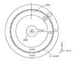
- FIG. 14D is a plan view showing shapes of the magnetic field generating coil and the power generating coil according to the modified example 23 of the embodiment.
- the configuration shown in the figure is an example showing an arrangement configuration of a power generation coil and a magnetic field generation coil when the power transmission coil is a spiral coil.
- a circular power generating coil 20Z1 is disposed at the center of the circle
- a power generating coil 20Z2 is disposed at the outermost periphery
- two magnetic field generating coils 10Z1 and 10Z2 are disposed between the power generating coils 20Z1 and 20Z2. ing.
- the boundary between the magnetic field generating coils 10Z1 and 10Z2 is a region where the z-direction magnetic field generated by the power transmission coil is zero or small.
- the magnetic field generating coil that forms a pair with the power generating coil 20Z1 at the center of the circle is the outer magnetic field generating coil 10Z2 of the two magnetic field generating coils.
- the magnetic field generating coil that forms a pair with the power generating coil 20Z2 at the outermost peripheral portion is the inner magnetic field generating coil 10Z1 of the two magnetic field generating coils.
- FIG. 14D applied to the spiral coil by the above configuration can similarly apply the concept in the configuration of FIG. 14B and FIG. 14C applied to the solenoid coil, and has the same effect.
- FIG. 15 is a graph showing a magnetic field distribution generated by a magnetic field generating coil including a plurality of rectangular magnetic field generating coil units. More specifically, this figure shows the x-direction distribution of the z-direction magnetic field generated by the magnetic field generating coil.
- the magnetic field distribution is a z-direction magnetic field distribution at a location about 10 mm away from the magnetic field generating coil in the z direction.
- the region in the x direction of the sensor coil array may be made to coincide with the region of the stable generated magnetic field excluding the end of the magnetic field generating coil array.
- one or more magnetic field generating coil units may be disposed outside the x-direction region of the sensor coil array.
- FIG. 16 is a plan view showing an arrangement relationship between the magnetic field generating coil and the sensor coil according to the embodiment.
- the figure shows the positional relationship between a sensor coil 40 and a magnetic field generating coil 10 in which a plurality of sensor coil units are electrically connected in series and continuously (in a one-stroke layout).
- the sensor coil 40 is an example having four rows of sensor coil units in the x direction and four rows of sensor coil units in the y direction.
- the plus and minus of the sensor coil unit represents the sign of the voltage appearing at the output terminal of the sensor coil 40 when a uniform magnetic flux change is applied to the sensor coil.
- the sum of electromotive forces of the positive sensor coil unit and the negative sensor coil unit is output to the output terminal.
- there are eight positive sensor coil units and two negative sensor coil units the numbers of both do not match, and there are six differences. If the magnetic fields passing through all the sensor coil units are the same, the electromotive force of the two positive sensor coil units and the electromotive force of the two negative sensor coil units are canceled, and the electromotive force contributing to the output voltage is 0V. Therefore, the electromotive force contributing to the output voltage is only the electromotive force of the six positive sensor coil units having the above difference.
- the sensor coil 40 determines the presence or absence of foreign matter by measuring the amount of change in the output voltage when foreign matter is present and not present, the absolute value of the output voltage V0 when no foreign matter is present is closer to 0V. Since the S / N ratio can be increased, the foreign matter detection sensitivity can be improved.
- the number of positive sensor coil units and the number of negative sensor coil units do not coincide in principle. This is because, as can be seen from the drawing, only the positive sensor coil unit is formed in the outermost peripheral portion of the sensor coil 40, and no negative sensor coil unit is formed. Therefore, there is a limit in bringing the output voltage of the sensor coil 40 formed by one stroke close to 0V.
- the magnetic field generating coil 10 is overlaid on the area where the sensor coil unit is not formed, and the end of the magnetic field generating coil 10 is placed at the upper end of the left and right positive sensor coil units. It is arranged inward by a distance p from the side. Thereby, the electromotive force of the surrounding positive sensor coil unit can be reduced. As a result, V0 can be made closer to 0V. Further, the arrangement relationship between the circular and donut-shaped sensor coil and the magnetic field generating coil, which are suitable for the spiral type coil, can be made the same.
- FIG. 17 is a diagram for explaining a first relationship between the sign of the sensor coil and the direction of the magnetic field generated by the magnetic field generating coil. Although there may be a large number of sensor coil units, here, description will be made using four sensor coil units.
- each sensor coil unit 40a to 40d is arranged so that the signs of adjacent sensor coil units are reversed.
- the length of the side of the sensor coil unit in the x direction and the length of the width of the magnetic field generating coil unit 11 in the x direction are substantially the same, and the sensor coil 40 and the magnetic field generation are made so that the wires extending in the y direction overlap.
- the coil 10 is arranged vertically (z direction).
- symbol of each sensor coil unit is determined by the layout method and its connection.
- the sign of the sensor coil unit matches the sign of the electromotive force of the sensor coil unit.
- the direction of the magnetic field varies depending on the location of the sensor coil unit.
- the sign of the electromotive force is determined by the logic of the sign of the sensor coil unit and the magnetic field direction.
- the sign of the electromotive force of the sensor coil units 40a to 40d is shown.
- symbol of the electromotive force of the sensor coil unit located in the generated magnetic field which goes to the back of the magnetic field generation coil unit 11 may correspond with the code
- a dash is added to the sign as + ',-'.
- the sensor coil units 40a and 40b coincide with the reference numerals of the sensor coil units.
- the sensor coil units 40c and 40d have opposite signs to the signs of the sensor coil units.
- the sensor coil unit 40a paying attention to the sensor coil unit 40a, consider a case where foreign matter exists on the side y in the y direction and the side x in the x direction.
- the sign of the electromotive force of the sensor coil unit is the same as the sign of the sensor coil 40. Since the adjacent sensor coil units have opposite signs, the foreign object detection sensitivity is deteriorated when a foreign object exists on the side that is the boundary between the adjacent sensor coil units.
- the reason for this is that in the two sensor coil units that are bordered by the side where the foreign substance exists, the absolute values of the electromotive force change amounts of the positive sensor coil unit and the negative sensor coil unit are approximately the same, and both are output.
- the sign of the voltage contributing to the voltage is reversed. This is because the amount of change in the electromotive force of the positive sensor coil unit and the amount of change in the electromotive force of the negative sensor coil unit cancel each other.
- the sensor coil unit 40c since the sensor coil unit 40c has a positive electromotive force, if there is a foreign object on the side y, the change in the electromotive force of the sensor coil unit 40a and the sensor coil unit 40c The change in electromotive force is not in the direction to cancel, but in the direction to increase. In other words, the foreign substance detection sensitivity on the side y is improved. This means that the detection sensitivity of the foreign matter on the side of the sensor coil unit can be greatly improved by the positional relationship between the sensor coil 40 and the magnetic field generating coil 10. On the other hand, when the current line is not on the boundary, the foreign matter detection sensitivity is low because the z-direction magnetic field is small.
- FIG. 18 is a diagram for explaining a second relationship between the sign of the sensor coil and the direction of the magnetic field generated by the magnetic field generating coil.
- the sign of the electromotive force of the sensor coil unit 40a is positive, and the sign of the electromotive force of the sensor coil unit 40c is negative. work. As a result, the foreign object detection sensitivity on the side y decreases. Moreover, since the direction of the magnetic field which passes the sensor coil unit 40a and the sensor coil unit 40c is the same, it is natural.
- the sensor coil unit 40b since the sensor coil unit 40b has a positive electromotive force, if there is a foreign object on the side x, the change in the electromotive force of the sensor coil unit 40a and the sensor coil unit 40b The change in electromotive force is not a direction to cancel, but a direction to increase. In other words, the foreign substance detection sensitivity on the side x is improved. This means that the detection sensitivity of the foreign matter on the side of the sensor coil unit can be greatly improved by the positional relationship between the sensor coil 40 and the magnetic field generating coil 10.
- the magnetic field generating coil substrate 110 includes a first magnetic field generating coil unit (magnetic field generating coil unit 11 in FIG. 17) and a second magnetic field generating coil unit (in FIG. 18) in which conductive wires are arranged along a rectangular outline.
- the first magnetic field generating coil unit and the second magnetic field generating coil unit are a magnetic field generating coil substrate so that a plane including the first magnetic field generating coil unit and a plane including the second magnetic field generating coil unit are parallel to each other.
- 110 is arranged so as to overlap the normal direction of each plane.
- the long side of the first magnetic field generating coil unit and the long side of the second magnetic field generating coil unit are orthogonal to each other in plan view (that is, viewed from the normal direction).
- the two magnetic field generating coils 10 may be driven separately or simultaneously. By driving simultaneously, a stronger magnetic field can be generated, and this also improves the foreign matter detection sensitivity. At this time, the sensitivity depending on the location of the foreign object detection is made uniform by setting the current directions of the two magnetic field generating coils to the same and the opposite directions.
- the output voltage V0 of the sensor coil is the sum of all the electromotive forces of the sensor coil unit
- the sum of the electromotive forces of all the sensor coil units is made close to 0V in the configurations of FIGS. It is necessary to keep.
- the number of positive sensor coil units arranged in the y direction and the number of negative sensor coil units having the same magnetic field direction generated by the magnetic field generating coil unit is made equal. If it does so, in all the sensor coil units which comprise a sensor coil array, the number of plus sensor coil units and the number of minus sensor coil units can be made to correspond.
- the above is a case where a rectangular magnetic field generating coil unit is arranged and the number of magnetic field generating coil units in the y direction is one.
- the same principle can be applied to improve the detection sensitivity of the foreign matter on the side. Is possible.
- FIG. 19 is a diagram for explaining a third relationship between the sign of the sensor coil and the direction of the magnetic field generated by the magnetic field generating coil.
- the left side of FIG. 19 shows a sensor coil 40 in which the signs of adjacent sensor coil units are reversed.
- a magnetic field generating coil 10-1 is shown in the center of FIG.
- the upper half magnetic field generating coil set 12a is arranged so that the magnetic field directions of the adjacent magnetic field generating coil units are opposite to each other, and the lower half magnetic field generating coil set 12b is vertically inverted from the magnetic field generating coil set 12a.
- the magnetic field directions of the upper and lower magnetic field generating coil units sandwiching the boundary are the same.
- the sensor coil unit constituting the sensor coil 40 and the magnetic field generating coil unit constituting the magnetic field generating coil 10-1 have the same size.
- FIG. 19 shows the sign of the electromotive force of each sensor coil unit obtained when the sensor coil 40 and the magnetic field generating coil 10-1 are aligned in the z-axis direction with their sides aligned.
- the signs of the electromotive forces of the upper half sensor coil units are all positive, and the signs of the electromotive forces of the lower half sensor coil units are all minus.
- V0 can be brought close to 0V.
- the electromotive forces of all the sensor coil units become positive or negative. In this case, it becomes difficult to bring V0 close to 0V.
- the magnetic field directions of the upper magnetic field generating coil set 12a and the lower magnetic field generating coil set 12b are formed by mirror inversion. Therefore, the place where the detection sensitivity of the foreign matter on the side is lowered is only the boundary portion between the magnetic field generating coil set 12a and the magnetic field generating coil set 12b.
- FIG. 20 is a diagram for explaining a fourth relationship between the sign of the sensor coil and the direction of the magnetic field generated by the magnetic field generating coil.
- the relationship between the sign of the sensor coil and the direction of the magnetic field generated by the magnetic field generating coil shown in FIG. 20 is a modification of the above relationship of FIG.
- the magnetic field directions of the magnetic field generating coil sets 12c and 12d arranged in the upper half are inverted mirrors, and the magnetic fields of the magnetic field generating coil sets 12d and 12c arranged in the upper half are reversed.
- the direction is mirrored up and down.
- the sides where the foreign object detection sensitivity decreases are the boundary between the magnetic field generating coil sets 12c and 12d in the upper half and the boundary between the magnetic field generating coil sets 12d and 12c in the lower half. And two places.
- the foreign matter detection sensitivity on the side can be improved.
- the foreign object detection sensitivity improves as the magnetic field passing through the sensor coil increases. For this reason, if the magnetic field generated by the power transmission coil is used in addition to the magnetic field generated by the magnetic field generating coil, the foreign object detection sensitivity can be further improved. Precisely, the foreign matter detection sensitivity is improved by increasing the time variation of the magnetic field. In the magnetic field waveform of the power transmission coil, the time variation of the magnetic field becomes the largest when the magnetic field strength becomes zero. That is, foreign matter detection may be performed when the magnetic field of the power transmission coil is close to zero.
- this time may be predicted to detect foreign matter by detecting the current of the feeding coil.
- a foreign object detection detection may be performed at the timing when the search coil is provided and the electromotive force is maximized. This timing is when the amount of time change of the magnetic field of the power feeding coil is maximized.
- the direction of the magnetic field of the magnetic field generating coil varies depending on the magnetic field generating coil unit, and the direction of the magnetic field generated by the power transmission coil may be negative or positive when the time variation of the magnetic flux is negative. For this reason, depending on the magnetic field generating coil unit, the direction of the magnetic field is opposite to the direction of the magnetic field of the power transmission coil, and the strength of the combined magnetic field may be reduced.
- foreign object detection sensitivity can be improved by performing foreign object detection under the conditions of all combinations of the direction of the current flowing through the magnetic field generating coil and the sign of the time variation of the magnetic field of the magnetic field generating coil. Can do.
- the magnetic field generated by the power transmission coil may change the sensor coil V0 or make it unstable, which may reduce the foreign matter detection sensitivity and accuracy. In this case, it may be desirable to reduce the influence of the magnetic field of the power transmission coil.
- foreign matter detection may be performed when the time change amount of the magnetic field of the power transmission coil is small or small. Specifically, it is the timing at which the magnetic field takes a peak value. There are two timings, a timing at which a positive peak value is obtained in one cycle and a timing at which a negative peak value is obtained. Foreign matter detection may be performed at any timing. At the above timing, the amount of time change of the magnetic field becomes zero, so that the influence on the sensor coil can be greatly reduced.
- FIG. 21 is a conceptual waveform diagram showing a temporal change in magnetic flux density generated by the power transmission coil.
- Timing A shown in the figure is the time at which the time change of the magnetic flux density becomes maximum.
- the drive circuit performs foreign object detection by driving the magnetic field generating coil at the timing A.
- the magnetic field generated by the power transmission coil and the magnetic field generated by the magnetic field generating coil are superimposed to increase the magnetic field in the foreign object detection space, so that the foreign object detection sensitivity can be improved.
- the drive circuit may drive the magnetic field generating coil and execute foreign object detection at timing B when the change in magnetic flux generated by the power transmission coil is small.
- the S / N ratio of the sensor coil is low and the foreign matter detection sensitivity is poor, this makes it possible to improve the foreign matter detection sensitivity.
- Timings A and B may be obtained by measuring the current and voltage of the power transmission coil, may be obtained from the timing of the gate signal of the inverter of the power transmission device, or a search coil is provided, You may obtain
- the drive circuit may drive the magnetic field generating coil at the timing when the presence / absence of the foreign material 160 is determined. Thereby, since a magnetic field is generated intermittently, both power consumption and electromagnetic radiation can be reduced.
- the drive circuit may drive the magnetic field generating coil by changing at least one of the current, voltage, power, and frequency of the power feeding coil and the power receiving coil.
- the drive circuit and power supply for driving the magnetic field generating coil can be simplified, so that the cost can be reduced by reducing the number of parts, the size can be reduced, and the reliability can be improved.
- the magnetic field generating coil may be provided on the power receiving unit side that is the secondary side. Specifically, the current flowing through the primary side magnetic field generating coil and the secondary side so that the z direction magnetic field generated by the primary side magnetic field generating coil and the z direction magnetic field generated by the secondary side magnetic field generating coil are intensified. The phase of the current flowing through the magnetic field generating coil is adjusted. As a result, the z-direction magnetic field is increased, and the foreign matter detection sensitivity is improved. In particular, the detection sensitivity of foreign matters existing in the space rather than on the road is improved.
- power may be generated using a secondary side magnetic field generating coil, and the generated power may be supplied to a load. Thereby, power generation efficiency can be improved.
- the coupling coefficient between the primary side magnetic field generating coil and the primary side feeding coil is preferably smaller than the coupling coefficient between the primary side feeding coil and the secondary side receiving coil.
- the coupling coefficient between the primary side magnetic field generating coil and the secondary power receiving coil is preferably smaller than the coupling coefficient between the primary power feeding coil and the secondary power receiving coil.
- the ratios of the coupling degree between the primary side magnetic field generating coil and the primary side feeding coil and the coupling degree between the primary side magnetic field generating coil and the secondary side receiving coil are both less than 10%. It is preferable. If the degree of coupling is greater than 10%, there may be a problem in power supply and demand from the power feeding coil to the power receiving coil.
- the magnetic field generating coil substrate on which the power generating coil and the magnetic field generating coil are formed is arranged in parallel with the sensor coil substrate. Moreover, it is preferable to make the interval as small as possible. Moreover, it is preferable to arrange them in contact.
- the magnetic field generating coil substrate on which the power generation coil and the magnetic field generating coil are formed is arranged in parallel with the xy plane of the power transmission coil. Moreover, it is preferable to make the interval as small as possible. Moreover, it is preferable to arrange them in contact.
- the sensor coil substrate is preferably disposed between the magnetic field generating coil substrate and the power transmission coil substrate.
- a magnetic field generating coil substrate may be disposed between the sensor coil substrate and the power transmission coil substrate.
- the materials of the constituent elements shown above are all exemplified for specifically explaining the present disclosure, and the present disclosure is not limited to the exemplified materials.
- the connection relationship between the components is exemplified for specifically explaining the present disclosure, and the connection relationship for realizing the functions of the present disclosure is not limited thereto.
- the non-contact electric power feeder 100 which concerns on the said embodiment is a system which charges the battery of the vehicle side from the electric power feeding coil arrange
- the foreign object detection device according to the present invention is not limited to this.
- the non-contact power supply device may be a system that supplies power to the traveling (moving) EV, and may be a foreign object detection device that detects foreign objects on the road.
- the foreign object detection device can be applied to a non-contact power feeding system of a moving body.
Landscapes
- Physics & Mathematics (AREA)
- Engineering & Computer Science (AREA)
- Life Sciences & Earth Sciences (AREA)
- Remote Sensing (AREA)
- General Physics & Mathematics (AREA)
- Electromagnetism (AREA)
- General Life Sciences & Earth Sciences (AREA)
- Geophysics (AREA)
- Environmental & Geological Engineering (AREA)
- Geology (AREA)
- Chemical & Material Sciences (AREA)
- Condensed Matter Physics & Semiconductors (AREA)
- Electrochemistry (AREA)
- Chemical Kinetics & Catalysis (AREA)
- Analytical Chemistry (AREA)
- Biochemistry (AREA)
- General Health & Medical Sciences (AREA)
- Immunology (AREA)
- Pathology (AREA)
- Health & Medical Sciences (AREA)
- Computer Networks & Wireless Communication (AREA)
- Power Engineering (AREA)
- Investigating Or Analyzing Materials By The Use Of Magnetic Means (AREA)
- Geophysics And Detection Of Objects (AREA)
- Charge And Discharge Circuits For Batteries Or The Like (AREA)
- Measuring Magnetic Variables (AREA)
Abstract
Description
[1.非接触給電装置の全体構成]
図1は、実施の形態に係る異物検出装置を含む非接触給電装置の概略構成図である。同図に示された非接触給電装置100は、給電コイル基板130と、受電コイル基板150と、磁界発生コイル基板110と、センサコイル基板140とを有する。 (Embodiment 1)
[1. Overall configuration of non-contact power feeding device]
FIG. 1 is a schematic configuration diagram of a non-contact power feeding device including a foreign object detection device according to an embodiment. The non-contact
図2は、発電コイルと磁界発生コイルとの関係の一例を表す図である。同図には、磁界発生コイル10と発電コイル20との接続関係が表されている。また、同図には、ソレノイド型の給電コイル30が示されている。給電コイル30は、コア31と巻き線32とを有している。なお、同図のx、y、z方向は、三次元の直交座標系である。給電コイル30の水平面をx方向とy方向とで規定(xy面)し、水平面と直交する鉛直方向(法線方向)をz方向と規定する。また、x方向は、給電コイル30の巻き線32の中心軸に沿った方向である。 [1-1. Power supply from the feeding coil to the magnetic field generating coil]
FIG. 2 is a diagram illustrating an example of a relationship between the power generation coil and the magnetic field generation coil. In the figure, the connection relationship between the magnetic
図3は、実施の形態に係る磁界発生コイルと給電コイルとの配置関係の一例を示す図である。図3の下段には、ソレノイド型の給電コイル30のz方向の磁界分布が表されている。x方向の中心領域の発生磁界が0となっている。給電コイル30からの発生磁界のみを利用したセンサコイル基板140の異物検出では、x方向の中心領域において検出感度が低下する。この検出感度の低下を改善すべく、図3の上段には、給電コイル30のx方向の中心領域に、磁界発生コイル10が配置されている。つまり、磁界発生コイル10は、給電コイル30と受電コイルとで形成される磁界のうち、磁界発生コイル10を含む平面の法線方向(z軸方向)の磁界成分が相対的に小さい、または、0である場所に配置される。これにより、x方向の中心領域における異物検出感度が向上し、給電コイル30上の全領域において、高精度に異物を検出することが可能となる。 [1-2. Magnetic flux supplementation by magnetic field generating coil]
FIG. 3 is a diagram illustrating an example of an arrangement relationship between the magnetic field generating coil and the feeding coil according to the embodiment. The lower part of FIG. 3 shows the magnetic field distribution in the z direction of the solenoid-type
上述したように、磁界発生コイルが発生する磁界は、センサコイルが利用する外部磁界として用いるものである。以下、本実施の形態に係る磁界発生コイルの構成について例示する。 [2. Configuration of magnetic field generating coil]
As described above, the magnetic field generated by the magnetic field generating coil is used as an external magnetic field used by the sensor coil. Hereinafter, the configuration of the magnetic field generating coil according to the present embodiment will be exemplified.
図11Aは、磁界発生コイルと異物との位置関係を表す図であり、図11Bは、磁界発生コイル-異物間距離と磁界発生コイルユニットの幅との関係を表すグラフである。図11Aには、典型的な磁界発生コイル10が実装された磁界発生コイル基板110と、異物160が存在するセンサコイル基板140との配置関係が示されている。ここで、磁界発生コイル基板110と異物160との距離をdとする。ここでは、異物160は、センサコイル基板140を覆う筐体の表面上に付着しているものと想定する。また、磁界発生コイル10を構成する磁界発生コイルユニット11Aのx方向の幅をaとする。 [3. Optimal shape of magnetic field generating coil]
FIG. 11A is a diagram showing the positional relationship between the magnetic field generating coil and the foreign matter, and FIG. 11B is a graph showing the relationship between the magnetic field generating coil-foreign matter distance and the width of the magnetic field generating coil unit. FIG. 11A shows an arrangement relationship between a magnetic field generating
aopt= (2.0±0.5)×d
である。 Here, the relationship between the distance d and the optimum width aopt is
aopt = (2.0 ± 0.5) × d
It is.
本実施の形態に係る異物検出装置1は、磁界発生コイルを駆動する駆動回路を有する。駆動回路は、磁界発生コイルに電圧(Vd1およびVd2)および電流を印加する。なお、駆動回路が印加する電流および電圧の波形は、正弦波、三角波、矩形波、およびパルス波などである。 [4. Driving circuit for magnetic field generating coil]
The foreign
以下では、磁界発生コイルに電圧および電流を供給する発電コイルが付加された異物検出装置について説明する。 [5. Configuration of magnetic field generating coil substrate having power generating coil]
Hereinafter, a foreign object detection device in which a power generation coil that supplies voltage and current to a magnetic field generation coil is added will be described.
以下では、磁界発生コイルとセンサコイルとの配置関係について説明する。 [6. Arrangement of magnetic field generating coil and sensor coil]
Below, the arrangement | positioning relationship between a magnetic field generation coil and a sensor coil is demonstrated.
図21は、電力伝送コイルにより発生する磁束密度の時間変化を表す概念波形図である。同図に示されたタイミングAは、磁束密度の時間変化が最大となる時刻である。駆動回路は、このタイミングAにおいて磁界発生コイルを駆動して異物検出を実行することが好ましい。これにより、電力伝送コイルにより発生する磁界と磁界発生コイルが発生させる磁界とが重畳されて、異物検出空間の磁界を大きくすることができるので、異物検出感度を向上させることが可能となる。 [7. Foreign object detection timing]
FIG. 21 is a conceptual waveform diagram showing a temporal change in magnetic flux density generated by the power transmission coil. Timing A shown in the figure is the time at which the time change of the magnetic flux density becomes maximum. It is preferable that the drive circuit performs foreign object detection by driving the magnetic field generating coil at the timing A. As a result, the magnetic field generated by the power transmission coil and the magnetic field generated by the magnetic field generating coil are superimposed to increase the magnetic field in the foreign object detection space, so that the foreign object detection sensitivity can be improved.
なお、磁界発生コイルを二次側である受電部側に設けてもよい。具体的には、一次側の磁界発生コイルが発生するz方向磁界と、二次側の磁界発生コイルが発生するz方向磁界が強めあうように、一次側磁界発生コイルに流れる電流と二次側磁界発生コイルに流れる電流の位相を調整する。これにより、z方向磁界が大きくなり、異物検出感度が向上する。特に、道路上でなく空間中に存在する異物の検出感度が向上する。 [8. Other arrangement of magnetic field generating coil]
The magnetic field generating coil may be provided on the power receiving unit side that is the secondary side. Specifically, the current flowing through the primary side magnetic field generating coil and the secondary side so that the z direction magnetic field generated by the primary side magnetic field generating coil and the z direction magnetic field generated by the secondary side magnetic field generating coil are intensified. The phase of the current flowing through the magnetic field generating coil is adjusted. As a result, the z-direction magnetic field is increased, and the foreign matter detection sensitivity is improved. In particular, the detection sensitivity of foreign matters existing in the space rather than on the road is improved.
以上、本発明に係る異物検出装置について、実施の形態および変形例に基づいて説明したが、本発明は、上記の実施の形態および変形例に限定されるものではない。 (Other embodiments)
As described above, the foreign object detection device according to the present invention has been described based on the embodiment and the modification. However, the present invention is not limited to the above-described embodiment and modification.
10,10A,10B,10C,10D,10E,10F,10G,10H,10J,10K,10L,10M,10N,10P,10Q,10R,10S,10T,10U,10V,10W1,10W2,10X,10Y,10Z1,10Z2,10-1,10-2 磁界発生コイル
11,11A,11B1,11B2,11C1,11C2,11D1,11D2,11E,11F1,11F2,11H,11K1,11K2,11L1,11L2,11U1,11U2,11V1,11V2,11Y1,11Y2 磁界発生コイルユニット
12a,12b,12c,12d,12F1,12F2,12G1,12G2,12G3 磁界発生コイルセット
13J1,13J2 並列結線
13J3,13J4,13P1,13P2,13Q1,13Q2,13R1,13R2,13S1,13S2 磁界発生コイルユニット線
20,20T,20U,20V,20W1,20W2,20X,20Y,20Z1,20Z2 発電コイル
21K1,21K2,21L1,21L2,21M1,21M2,21N1,21N2,21P1H,21P1L,21P2H,21P2L,21P3H,21P3L,21P4H,21P4L,21Q1H,21Q1L,21Q2H,21Q2L,21Q3H,21Q3L,21Q4H,21Q4L,21R1H,21R1L,21R2H,21R2L,21S1H,21S1L,21S2H,21S2L スイッチ
30 給電コイル
31 コア
32 巻き線
40 センサコイル
40a,40b,40c,40d センサコイルユニット
100 非接触給電装置
110 磁界発生コイル基板
130 給電コイル基板
140 センサコイル基板
150 受電コイル基板
160 異物 1 Foreign object detection device 10, 10A, 10B, 10C, 10D, 10E, 10F, 10G, 10H, 10J, 10K, 10L, 10M, 10N, 10P, 10Q, 10R, 10S, 10T, 10U, 10V, 10W1, 10W2, 10X, 10Y, 10Z1, 10Z2, 10-1, 10-2 Magnetic field generating coils 11, 11A, 11B1, 11B2, 11C1, 11C2, 11D1, 11D2, 11E, 11F1, 11F2, 11H, 11K1, 11K2, 11L1, 11L2, 11U1, 11U2, 11V1, 11V2, 11Y1, 11Y2 Magnetic field generating coil units 12a, 12b, 12c, 12d, 12F1, 12F2, 12G1, 12G2, 12G3 Magnetic field generating coil set 13J1, 13J2 Parallel connection 13J3, 13J4, 13P1, 13P 2, 13Q1, 13Q2, 13R1, 13R2, 13S1, 13S2 Magnetic field generating coil unit wires 20, 20T, 20U, 20V, 20W1, 20W2, 20X, 20Y, 20Z1, 20Z2 Power generation coils 21K1, 21K2, 21L1, 21L1, 21M1, 21M2 , 21N1, 21N2, 21P1H, 21P1L, 21P2H, 21P2L, 21P3H, 21P3L, 21P4H, 21P4L, 21Q1H, 21Q1L, 21Q2H, 21Q2L, 21Q3H, 21Q3L, 21Q4H, 21Q2L, 21R1H21L2S, 21R1H21R1L , 21S2L switch 30 feeding coil 31 core 32 winding 40 sensor coils 40a, 40b, 40c, 40d sensor coil unit 10 0 Non-contact power supply device 110 Magnetic field generating coil substrate 130 Power supply coil substrate 140 Sensor coil substrate 150 Power receiving coil substrate 160 Foreign matter
Claims (20)
- 給電部から受電部へ非接触で給電を行なう非接触給電システムに搭載される異物検出装置であって、
前記給電部と前記受電部との間に存在する異物により変化する磁束量を検出する磁界センサと、
前記給電部および前記受電部とは別に設けられ、磁界発生コイルユニットを有し、前記磁界センサを駆動するための磁界を発生させる磁界発生部と、を備えた、
異物検出装置。 A foreign object detection device mounted in a non-contact power feeding system that performs non-contact power feeding from a power feeding unit to a power receiving unit,
A magnetic field sensor that detects the amount of magnetic flux that changes due to a foreign object existing between the power feeding unit and the power receiving unit;
A magnetic field generation unit that is provided separately from the power supply unit and the power reception unit, includes a magnetic field generation coil unit, and generates a magnetic field for driving the magnetic field sensor;
Foreign object detection device. - 前記磁界発生部は、複数の前記磁界発生コイルユニットを有し、
前記複数の前記磁界発生コイルユニットのうちの少なくとも2つは、電気的に直列かつ連続して形成されている、
請求項1に記載の異物検出装置。 The magnetic field generation unit includes a plurality of the magnetic field generation coil units,
At least two of the plurality of the magnetic field generating coil units are electrically connected in series and continuously.
The foreign object detection device according to claim 1. - 前記磁界発生部は、
複数の前記磁界発生コイルユニットと、
前記複数の前記磁界発生コイルユニットのそれぞれに電流を供給するための複数の端子と、
前記複数の前記磁界発生コイルユニットのそれぞれと、対応する前記複数の端子のそれぞれとの間に設けられ、前記複数の磁界発生コイルユニットのそれぞれに電流を供給する、および、供給しないを選択する複数の第1スイッチ素子と、を有する、
請求項1に記載の異物検出装置。 The magnetic field generator is
A plurality of the magnetic field generating coil units;
A plurality of terminals for supplying a current to each of the plurality of magnetic field generating coil units;
A plurality that is provided between each of the plurality of magnetic field generating coil units and each of the corresponding plurality of terminals, and selects whether or not to supply current to each of the plurality of magnetic field generating coil units. A first switching element of
The foreign object detection device according to claim 1. - 前記磁界発生部は、
複数の前記磁界発生コイルユニットと、
前記複数の前記磁界発生コイルユニットのそれぞれに電流を供給するための複数の端子と、
前記複数の磁界発生コイルユニットのそれぞれと対応する前記複数の端子のそれぞれとの間に設けられ、前記複数の磁界発生コイルユニットのそれぞれに流れる電流の方向を変化させる複数の第2スイッチ素子と、を有する、
請求項1に記載の異物検出装置。 The magnetic field generator is
A plurality of the magnetic field generating coil units;
A plurality of terminals for supplying a current to each of the plurality of magnetic field generating coil units;
A plurality of second switch elements that are provided between each of the plurality of magnetic field generating coil units and corresponding to the plurality of terminals, and change a direction of a current flowing through each of the plurality of magnetic field generating coil units; Having
The foreign object detection device according to claim 1. - 前記磁界発生部は、複数の前記磁界発生コイルユニットを有し、
前記複数の前記磁界発生コイルユニットのそれぞれは、矩形又は円環の輪郭に沿って導電線が配置されて形成されており、
前記矩形の短辺の長さまたは前記円環の幅である前記磁界発生コイルユニットの幅は、前記磁界発生コイルユニットを含む平面と前記異物との距離の1.5倍以上、2.5倍以下である、
請求項1~4のいずれか1項に記載の異物検出装置。 The magnetic field generation unit includes a plurality of the magnetic field generation coil units,
Each of the plurality of magnetic field generating coil units is formed by arranging conductive lines along the outline of a rectangle or a ring,
The width of the magnetic field generating coil unit which is the length of the short side of the rectangle or the width of the ring is 1.5 times or more and 2.5 times the distance between the plane including the magnetic field generating coil unit and the foreign matter. Is
The foreign object detection device according to any one of claims 1 to 4. - 前記磁界発生部は、複数の前記磁界発生コイルユニットを備え、
前記複数の前記磁界発生コイルユニットのそれぞれは、一定の間隔で平面上に配置されており、
前記異物検出装置は、前記異物が存在することにより変化する磁束量を電圧信号として検出する複数のセンサコイルユニットを有する前記磁界センサをさらに備え、
前記複数の磁界発生コイルユニットのそれぞれの第1方向における幅は、前記複数のセンサコイルユニットのそれぞれの前記第1方向における幅と同じである、
請求項1~5のいずれか1項に記載の異物検出装置。 The magnetic field generation unit includes a plurality of the magnetic field generation coil units,
Each of the plurality of magnetic field generating coil units is arranged on a plane at a constant interval,
The foreign object detection device further includes the magnetic field sensor having a plurality of sensor coil units that detect, as voltage signals, the amount of magnetic flux that changes due to the presence of the foreign object,
The width in the first direction of each of the plurality of magnetic field generating coil units is the same as the width in the first direction of each of the plurality of sensor coil units.
The foreign object detection device according to any one of claims 1 to 5. - 前記磁界発生部は、複数の前記磁界発生コイルユニットを備え、
前記複数の前記磁界発生コイルユニットは、長方形の輪郭に沿って導電線が配置された第1の磁界発生コイルユニットおよび第2の磁界発生コイルユニットを含み、
前記第1の磁界発生コイルユニットと前記第2の磁界発生コイルユニットとは、前記第1の磁界発生コイルユニットを含む第1平面と前記第2の磁界発生コイルユニットを含む第2平面とが平行となるよう、前記第1、第2平面の法線方向に重ねられて配置され、
前記第1の磁界発生コイルユニットの長辺と、前記第2の磁界発生コイルユニットの長辺とは、前記法線方向から見て直交している、
請求項1~6のいずれか1項に記載の異物検出装置。 The magnetic field generation unit includes a plurality of the magnetic field generation coil units,
The plurality of magnetic field generating coil units include a first magnetic field generating coil unit and a second magnetic field generating coil unit in which conductive wires are arranged along a rectangular outline,
In the first magnetic field generating coil unit and the second magnetic field generating coil unit, a first plane including the first magnetic field generating coil unit and a second plane including the second magnetic field generating coil unit are parallel to each other. So as to be overlaid in the normal direction of the first and second planes,
The long side of the first magnetic field generating coil unit and the long side of the second magnetic field generating coil unit are orthogonal to each other when viewed from the normal direction.
The foreign matter detection device according to any one of claims 1 to 6. - 前記非接触給電システムは、給電コイルを有する前記給電部と、
受電コイルを有する前記受電部と、を備えたものであり、
前記磁界発生部は、前記給電コイルと前記受電コイルとで形成される磁界のうち、前記磁界発生コイルユニットを含む平面の法線方向の磁界成分が相対的に小さい、または、0である場所に配置される、
請求項1~7のいずれか1項に記載の異物検出装置。 The non-contact power supply system includes the power supply unit including a power supply coil,
The power receiving unit having a power receiving coil, and
The magnetic field generation unit is a place where a magnetic field component in a normal direction of a plane including the magnetic field generation coil unit is relatively small or zero among magnetic fields formed by the power feeding coil and the power receiving coil. Arranged,
The foreign object detection device according to any one of claims 1 to 7. - 給電コイルを有する前記給電部と、
受電コイルを有する前記受電部と、をさらに備え、
前記磁界発生部と前記給電コイルとの磁気結合の係数、および、前記磁界発生部と前記受電コイルとの磁気結合の係数は、ともに10%以下である、
請求項1~8のいずれか1項に記載の異物検出装置。 The power supply unit having a power supply coil;
The power receiving unit having a power receiving coil,
The magnetic coupling coefficient between the magnetic field generator and the feeding coil, and the magnetic coupling coefficient between the magnetic field generator and the power receiving coil are both 10% or less.
The foreign object detection device according to any one of claims 1 to 8. - 前記磁界発生部を駆動する駆動回路をさらに備えた、
請求項1~9のいずれか1項に記載の異物検出装置。 A drive circuit for driving the magnetic field generator;
The foreign object detection device according to any one of claims 1 to 9. - 前記駆動回路は、前記磁界発生コイルユニットに流れる電流の時間微分値が1A/50ns以上となるよう前記磁界発生部を駆動する、
請求項10に記載の異物検出装置。 The drive circuit drives the magnetic field generation unit so that a time differential value of a current flowing through the magnetic field generation coil unit is 1 A / 50 ns or more;
The foreign object detection device according to claim 10. - 前記駆動回路は、前記磁界発生コイルユニットへ供給する、電流、電圧、電力および周波数の少なくとも1つの絶対値および時間的変化量の少なくとも一方を変化させて前記磁界発生部を駆動する、
請求項10、11のいずれか1項に記載の異物検出装置。 The drive circuit drives the magnetic field generation unit by changing at least one of an absolute value and a temporal change amount of at least one of current, voltage, power and frequency supplied to the magnetic field generation coil unit;
The foreign object detection device according to claim 10. - 前記磁界発生部は、発電コイルをさらに有し、
前記発電コイルは、前記給電部および前記受電部が発生する磁界を利用して起電力を生成し、生成した前記起電力を磁界発生コイルユニットへ供給する、
請求項1~12のいずれか1項に記載の異物検出装置。 The magnetic field generator further includes a power generation coil,
The power generating coil generates an electromotive force using a magnetic field generated by the power feeding unit and the power receiving unit, and supplies the generated electromotive force to a magnetic field generating coil unit.
The foreign object detection device according to any one of claims 1 to 12. - 前記磁界発生部を駆動する駆動回路をさらに備え、
前記発電コイルで生成された前記起電力は、前記駆動回路を含む前記異物検出装置の回路に供給される、
請求項13に記載の異物検出装置。 A drive circuit for driving the magnetic field generator;
The electromotive force generated by the power generation coil is supplied to a circuit of the foreign object detection device including the drive circuit.
The foreign object detection device according to claim 13. - 前記給電部と前記受電部とで形成される磁界のうち、前記磁界発生コイルユニットを含む平面の法線方向の磁界成分が0になる場所に、前記磁界発生コイルユニットを形成する導電線の一部が配置されている、
請求項13に記載の異物検出装置。 One of the conductive wires forming the magnetic field generating coil unit at a location where the magnetic field component in the normal direction of the plane including the magnetic field generating coil unit becomes zero among the magnetic fields formed by the power feeding unit and the power receiving unit. Part is located,
The foreign object detection device according to claim 13. - 前記駆動回路は、前記異物の有無の判定を行うタイミングで、前記磁界発生部を駆動する、
請求項10に記載の異物検出装置。 The drive circuit drives the magnetic field generation unit at a timing for determining the presence or absence of the foreign matter.
The foreign object detection device according to claim 10. - 前記駆動回路は、前記給電部と前記受電部とで形成される磁界の変化の絶対値が最小となったタイミングで、前記磁界発生部を駆動する、
請求項10に記載の異物検出装置。 The drive circuit drives the magnetic field generation unit at a timing at which an absolute value of a change in magnetic field formed by the power feeding unit and the power reception unit is minimized.
The foreign object detection device according to claim 10. - 前記駆動回路は、前記給電部または前記受電部の電流が0のタイミングで、前記磁界発生部を駆動する、
請求項10に記載の異物検出装置。 The drive circuit drives the magnetic field generating unit at a timing when the current of the power feeding unit or the power receiving unit is 0.
The foreign object detection device according to claim 10. - 前記駆動回路は、前記給電部または前記受電部から高周波磁界が発生する時間を避けて、前記磁界発生部を駆動する、
請求項10に記載の異物検出装置。 The drive circuit drives the magnetic field generation unit while avoiding a time during which a high frequency magnetic field is generated from the power supply unit or the power reception unit.
The foreign object detection device according to claim 10. - 前記駆動回路は、前記給電部および前記受電部の電流、電圧、電力および周波数の少なくとも1つを変化させることにより、前記磁界発生部を駆動する、
請求項10に記載の異物検出装置。 The drive circuit drives the magnetic field generation unit by changing at least one of current, voltage, power, and frequency of the power supply unit and the power reception unit.
The foreign object detection device according to claim 10.
Priority Applications (4)
| Application Number | Priority Date | Filing Date | Title |
|---|---|---|---|
| EP15853930.4A EP3214728B1 (en) | 2014-10-31 | 2015-10-23 | Foreign matter detection device |
| JP2016556215A JP6660531B2 (en) | 2014-10-31 | 2015-10-23 | Foreign object detection device |
| CN201580046449.4A CN106663964B (en) | 2014-10-31 | 2015-10-23 | Detection device for foreign matter |
| US15/504,053 US9885798B2 (en) | 2014-10-31 | 2015-10-23 | Foreign matter detection device |
Applications Claiming Priority (2)
| Application Number | Priority Date | Filing Date | Title |
|---|---|---|---|
| JP2014-223730 | 2014-10-31 | ||
| JP2014223730 | 2014-10-31 |
Publications (1)
| Publication Number | Publication Date |
|---|---|
| WO2016067575A1 true WO2016067575A1 (en) | 2016-05-06 |
Family
ID=55856941
Family Applications (1)
| Application Number | Title | Priority Date | Filing Date |
|---|---|---|---|
| PCT/JP2015/005336 WO2016067575A1 (en) | 2014-10-31 | 2015-10-23 | Foreign matter detection device |
Country Status (5)
| Country | Link |
|---|---|
| US (1) | US9885798B2 (en) |
| EP (1) | EP3214728B1 (en) |
| JP (1) | JP6660531B2 (en) |
| CN (1) | CN106663964B (en) |
| WO (1) | WO2016067575A1 (en) |
Cited By (1)
| Publication number | Priority date | Publication date | Assignee | Title |
|---|---|---|---|---|
| JP2021040363A (en) * | 2019-08-30 | 2021-03-11 | 株式会社Ihi | Foreign matter countermeasure apparatus and power transmission apparatus |
Families Citing this family (9)
| Publication number | Priority date | Publication date | Assignee | Title |
|---|---|---|---|---|
| CN206004419U (en) * | 2014-03-14 | 2017-03-08 | 株式会社村田制作所 | Wireless power supply |
| JP6992445B2 (en) * | 2017-11-27 | 2022-01-13 | 富士電機株式会社 | Coin detection antenna and coin processing device |
| CN109638975B (en) * | 2019-01-10 | 2024-04-02 | 深圳大学 | Metallic foreign matter detection coil coiling structure based on electromagnetic induction |
| CN109787376B (en) * | 2019-01-10 | 2024-04-02 | 深圳大学 | Inductive power transfer metal foreign matter detection system and method |
| CN109950955A (en) * | 2019-03-29 | 2019-06-28 | 努比亚技术有限公司 | Charging method, device and terminal device based on cradle |
| FR3096190B1 (en) * | 2019-05-17 | 2021-04-16 | Continental Automotive | Method of inductive charging control of user equipment and associated charging device for motor vehicle |
| JP7378586B2 (en) * | 2020-04-01 | 2023-11-13 | 三菱電機株式会社 | Power generation elements, magnetic sensors, encoders and motors using them |
| CN111679327A (en) * | 2020-06-03 | 2020-09-18 | 国网黑龙江省电力有限公司电力科学研究院 | Wireless charging tray metal detection probe with magnetic structure |
| WO2022153356A1 (en) * | 2021-01-12 | 2022-07-21 | 三菱電機株式会社 | Power generation element, magnetic sensor, and encoder |
Citations (4)
| Publication number | Priority date | Publication date | Assignee | Title |
|---|---|---|---|---|
| JP2012075200A (en) * | 2010-09-27 | 2012-04-12 | Toshiba Corp | Wireless power transmission apparatus |
| WO2014011776A2 (en) * | 2012-07-13 | 2014-01-16 | Qualcomm Incorporated | Systems, methods, and apparatus for detection of metal objects in a predetermined space |
| JP2015204707A (en) * | 2014-04-15 | 2015-11-16 | トヨタ自動車株式会社 | non-contact power transmission device |
| JP2015211536A (en) * | 2014-04-25 | 2015-11-24 | トヨタ自動車株式会社 | Power transmission device and power reception device |
Family Cites Families (7)
| Publication number | Priority date | Publication date | Assignee | Title |
|---|---|---|---|---|
| JP2012016125A (en) * | 2010-06-30 | 2012-01-19 | Panasonic Electric Works Co Ltd | Non-contact power supply system, and metal foreign substance detector of non-contact power supply system |
| JP5625723B2 (en) * | 2010-10-15 | 2014-11-19 | ソニー株式会社 | Electronic device, power supply method and power supply system |
| JP5853199B2 (en) * | 2011-08-25 | 2016-02-09 | パナソニックIpマネジメント株式会社 | Metallic foreign matter detection method for non-contact power feeding system, non-contact power feeding device, power receiving device provided in electrical equipment, and non-contact power feeding system |
| JP5967989B2 (en) * | 2012-03-14 | 2016-08-10 | ソニー株式会社 | Detecting device, power receiving device, power transmitting device, and non-contact power feeding system |
| JP2013192391A (en) | 2012-03-14 | 2013-09-26 | Sony Corp | Detecting apparatus, power receiving apparatus, power transmitting apparatus, and contactless power supply system |
| US9906048B2 (en) * | 2012-12-28 | 2018-02-27 | Panasonic Intellectual Property Management Co., Ltd. | Non-contact power supply apparatus |
| CN104124772B (en) * | 2013-04-28 | 2018-11-20 | 海尔集团技术研发中心 | Radio energy transmission system, transmitting terminal, receiving end and its awakening method |
-
2015
- 2015-10-23 CN CN201580046449.4A patent/CN106663964B/en active Active
- 2015-10-23 EP EP15853930.4A patent/EP3214728B1/en active Active
- 2015-10-23 US US15/504,053 patent/US9885798B2/en active Active
- 2015-10-23 JP JP2016556215A patent/JP6660531B2/en active Active
- 2015-10-23 WO PCT/JP2015/005336 patent/WO2016067575A1/en active Application Filing
Patent Citations (4)
| Publication number | Priority date | Publication date | Assignee | Title |
|---|---|---|---|---|
| JP2012075200A (en) * | 2010-09-27 | 2012-04-12 | Toshiba Corp | Wireless power transmission apparatus |
| WO2014011776A2 (en) * | 2012-07-13 | 2014-01-16 | Qualcomm Incorporated | Systems, methods, and apparatus for detection of metal objects in a predetermined space |
| JP2015204707A (en) * | 2014-04-15 | 2015-11-16 | トヨタ自動車株式会社 | non-contact power transmission device |
| JP2015211536A (en) * | 2014-04-25 | 2015-11-24 | トヨタ自動車株式会社 | Power transmission device and power reception device |
Cited By (2)
| Publication number | Priority date | Publication date | Assignee | Title |
|---|---|---|---|---|
| JP2021040363A (en) * | 2019-08-30 | 2021-03-11 | 株式会社Ihi | Foreign matter countermeasure apparatus and power transmission apparatus |
| JP7331560B2 (en) | 2019-08-30 | 2023-08-23 | 株式会社Ihi | Contaminant countermeasure device and power transmission device |
Also Published As
| Publication number | Publication date |
|---|---|
| EP3214728B1 (en) | 2019-02-27 |
| US9885798B2 (en) | 2018-02-06 |
| CN106663964B (en) | 2019-10-25 |
| EP3214728A4 (en) | 2017-12-06 |
| US20170276820A1 (en) | 2017-09-28 |
| JPWO2016067575A1 (en) | 2017-08-10 |
| JP6660531B2 (en) | 2020-03-11 |
| EP3214728A1 (en) | 2017-09-06 |
| CN106663964A (en) | 2017-05-10 |
Similar Documents
| Publication | Publication Date | Title |
|---|---|---|
| WO2016067575A1 (en) | Foreign matter detection device | |
| CN107294224B (en) | Multi-coil excitation magnetic field coupling type wireless charging platform | |
| CN104242682B (en) | For motor or the inverter of generator | |
| WO2010087080A1 (en) | Current detection device | |
| CN105957859A (en) | Semiconductor power module and power conversion apparatus using the same | |
| US11070163B2 (en) | Driving power supply device | |
| JP2013098425A (en) | Power semiconductor module | |
| CN102810979A (en) | Semiconductor module and driving apparatus including semiconductor module | |
| US20130154353A1 (en) | Space-division multiple power feeding and collecting apparatus | |
| US10836266B2 (en) | Inductively transferring electric energy to a vehicle using consecutive segments which are operated at the same time | |
| CN103765750A (en) | Power conversion device | |
| CN111213312B (en) | Inverter control substrate | |
| CN110235356A (en) | Electric motor and controller device | |
| CN102687379A (en) | Power switch arrangement for an inverter | |
| JP5785119B2 (en) | Power supply | |
| CN104380587A (en) | Power conversion apparatus | |
| CN109149958A (en) | Semiconductor device | |
| EP3526479B1 (en) | Balanced switching amplifier for a magnetic bearing assembly | |
| US20190296573A1 (en) | Wireless power transfer with generalized harmonic current | |
| JP2016086491A (en) | Semiconductor device | |
| US20220084741A1 (en) | Magnetic component and power conversion apparatus including the same | |
| KR20170008713A (en) | Wireless Power Transfer System Having Two-Phase Power Supply Unit | |
| US9941833B2 (en) | Converter for hybrid electric vehicle system | |
| CN103532475A (en) | Rotary electric machine control apparatus and electric power steering system using the same | |
| KR101231848B1 (en) | Apparatus for Providing Power for Electric Vehicle and Driving Method Thereof |
Legal Events
| Date | Code | Title | Description |
|---|---|---|---|
| 121 | Ep: the epo has been informed by wipo that ep was designated in this application |
Ref document number: 15853930 Country of ref document: EP Kind code of ref document: A1 |
|
| ENP | Entry into the national phase |
Ref document number: 2016556215 Country of ref document: JP Kind code of ref document: A |
|
| REEP | Request for entry into the european phase |
Ref document number: 2015853930 Country of ref document: EP |
|
| WWE | Wipo information: entry into national phase |
Ref document number: 2015853930 Country of ref document: EP |
|
| WWE | Wipo information: entry into national phase |
Ref document number: 15504053 Country of ref document: US |
|
| NENP | Non-entry into the national phase |
Ref country code: DE |