WO2016063603A1 - Solid-state imaging device and electronic endoscope provided with solid-state imaging device - Google Patents
Solid-state imaging device and electronic endoscope provided with solid-state imaging device Download PDFInfo
- Publication number
- WO2016063603A1 WO2016063603A1 PCT/JP2015/073112 JP2015073112W WO2016063603A1 WO 2016063603 A1 WO2016063603 A1 WO 2016063603A1 JP 2015073112 W JP2015073112 W JP 2015073112W WO 2016063603 A1 WO2016063603 A1 WO 2016063603A1
- Authority
- WO
- WIPO (PCT)
- Prior art keywords
- imaging device
- solid
- state imaging
- core wire
- connecting portion
- Prior art date
Links
Images


Classifications
-
- A—HUMAN NECESSITIES
- A61—MEDICAL OR VETERINARY SCIENCE; HYGIENE
- A61B—DIAGNOSIS; SURGERY; IDENTIFICATION
- A61B1/00—Instruments for performing medical examinations of the interior of cavities or tubes of the body by visual or photographical inspection, e.g. endoscopes; Illuminating arrangements therefor
- A61B1/04—Instruments for performing medical examinations of the interior of cavities or tubes of the body by visual or photographical inspection, e.g. endoscopes; Illuminating arrangements therefor combined with photographic or television appliances
- A61B1/05—Instruments for performing medical examinations of the interior of cavities or tubes of the body by visual or photographical inspection, e.g. endoscopes; Illuminating arrangements therefor combined with photographic or television appliances characterised by the image sensor, e.g. camera, being in the distal end portion
- A61B1/051—Details of CCD assembly
-
- A—HUMAN NECESSITIES
- A61—MEDICAL OR VETERINARY SCIENCE; HYGIENE
- A61B—DIAGNOSIS; SURGERY; IDENTIFICATION
- A61B1/00—Instruments for performing medical examinations of the interior of cavities or tubes of the body by visual or photographical inspection, e.g. endoscopes; Illuminating arrangements therefor
- A61B1/04—Instruments for performing medical examinations of the interior of cavities or tubes of the body by visual or photographical inspection, e.g. endoscopes; Illuminating arrangements therefor combined with photographic or television appliances
-
- G—PHYSICS
- G02—OPTICS
- G02B—OPTICAL ELEMENTS, SYSTEMS OR APPARATUS
- G02B23/00—Telescopes, e.g. binoculars; Periscopes; Instruments for viewing the inside of hollow bodies; Viewfinders; Optical aiming or sighting devices
- G02B23/24—Instruments or systems for viewing the inside of hollow bodies, e.g. fibrescopes
- G02B23/2476—Non-optical details, e.g. housings, mountings, supports
- G02B23/2484—Arrangements in relation to a camera or imaging device
-
- H—ELECTRICITY
- H04—ELECTRIC COMMUNICATION TECHNIQUE
- H04N—PICTORIAL COMMUNICATION, e.g. TELEVISION
- H04N23/00—Cameras or camera modules comprising electronic image sensors; Control thereof
-
- H—ELECTRICITY
- H04—ELECTRIC COMMUNICATION TECHNIQUE
- H04N—PICTORIAL COMMUNICATION, e.g. TELEVISION
- H04N23/00—Cameras or camera modules comprising electronic image sensors; Control thereof
- H04N23/50—Constructional details
- H04N23/54—Mounting of pick-up tubes, electronic image sensors, deviation or focusing coils
-
- H—ELECTRICITY
- H04—ELECTRIC COMMUNICATION TECHNIQUE
- H04N—PICTORIAL COMMUNICATION, e.g. TELEVISION
- H04N23/00—Cameras or camera modules comprising electronic image sensors; Control thereof
- H04N23/50—Constructional details
- H04N23/555—Constructional details for picking-up images in sites, inaccessible due to their dimensions or hazardous conditions, e.g. endoscopes or borescopes
-
- G—PHYSICS
- G02—OPTICS
- G02B—OPTICAL ELEMENTS, SYSTEMS OR APPARATUS
- G02B23/00—Telescopes, e.g. binoculars; Periscopes; Instruments for viewing the inside of hollow bodies; Viewfinders; Optical aiming or sighting devices
- G02B23/24—Instruments or systems for viewing the inside of hollow bodies, e.g. fibrescopes
- G02B23/26—Instruments or systems for viewing the inside of hollow bodies, e.g. fibrescopes using light guides
Definitions
- the present invention relates to a solid-state imaging device disposed at a distal end portion of an insertion portion of an electronic endoscope.
- An imaging unit that is a solid-state imaging device that can be introduced into the living body or structure from the outside to observe an area that is difficult to observe, such as the inside of a living body or the inside of a structure, and that captures an optical image
- An electronic endoscope equipped with the above is used in, for example, the medical field or the industrial field.
- An imaging unit of an electronic endoscope includes an objective lens that forms a subject image, and a CCD (Charge Coupled Device), a CMOS (Complementary Metal Oxide Semiconductor) sensor, etc. that are generally disposed on the imaging surface of the objective lens.
- An image sensor is provided.
- an imaging unit disclosed in Japanese Patent Laid-Open No. 2005-304876 is known.
- This conventional imaging unit of an electronic endoscope has a configuration in which outer conductors of a plurality of coaxial signal lines are wound around a ground jumper line and connected to a circuit board.
- the imaging unit is also required to be downsized.
- the shield bundle in which the shields of a plurality of coaxial signal lines are bundled is electrically connected to the circuit board through the ground jumper wire, the longitudinal shortening of the multilayer substrate is hindered.
- the binding portion of the outer conductor swells in the outer diameter direction and inhibits the diameter reduction.
- the distal end portion of the insertion portion in which the imaging unit is incorporated becomes longer and the outer diameter becomes larger, which not only prevents the insertion portion from being reduced in diameter.
- the hard length since the hard length is extended, it has been a factor of lowering the insertability.
- the present invention has been made in view of the above-described circumstances, and is a compact solid-state imaging device that contributes to reducing the diameter of the insertion portion and shortening the hard length, and an electronic endoscope including the solid-state imaging device.
- the purpose is to provide a mirror.
- a solid-state imaging device includes a solid-state imaging device that detects an image of a subject, a hard board that is electrically connected to the imaging device, and a signal cable that includes at least one coaxial line.
- the hard substrate includes a first surface having a core wire connection portion to which the coaxial wire is connected, and an outer conductor connection portion to which the outer conductor of the coaxial wire is connected.
- a second surface substantially parallel to the first surface, and the coaxial line is connected substantially parallel to the first and second surfaces of the hard substrate.
- An electronic endoscope includes an imaging element that detects a subject image, a hard substrate that is electrically connected to the imaging element, and a signal cable that includes at least one coaxial line.
- the hard substrate includes a first surface having a core wire connecting portion to which the coaxial wire is connected, and an outer conductor connecting portion to which the outer conductor of the coaxial wire is connected.
- a solid-state imaging device comprising: a second surface substantially parallel to the first surface, wherein the coaxial line is connected substantially parallel to the first and second surfaces of the hard substrate; and the solid-state imaging
- the apparatus includes an insertion portion built in the distal end portion, and the signal cable is disposed substantially parallel to the longitudinal direction of the insertion portion.
- the figure which shows the structure of the endoscope of 1 aspect of this invention The front view which shows the structure of the front-end
- Sectional drawing which shows the structure of the external conductor connection part of the circuit board of the imaging unit of the 1st modification similarly
- Sectional drawing which shows the structure of the imaging unit along the XII-XII line of FIG.
- the side view which shows the structure of the circuit board to which the power source line and several signal line of the 3rd modification were connected
- Sectional drawing which shows the structure of the imaging unit along the XIV-XIV line of FIG.
- FIG. 21 is a cross-sectional view showing the configuration of the imaging unit along the line XXII-XXII in FIG.
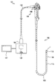
- FIG. 1 is a diagram showing the configuration of the endoscope
- FIG. 2 is a front view showing the configuration of the distal end portion of the insertion portion
- FIG. 3 is a cross-sectional view showing the configuration of the distal end portion taken along line III-III in FIG. 4 is a cross-sectional view showing the structure of the tip portion along line IV-IV in FIG. 3
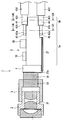
- FIG. 5 is a partial cross-sectional view showing the structure of the imaging unit
- FIG. 6 is a cross-sectional view showing the structure of the composite cable.
- 7 is a sectional view showing the configuration of the imaging unit along the line VII-VII in FIG. 5
- FIG. 8 is a sectional view showing the configuration of the imaging unit along the line VIII-VIII in FIG. 5, and
- FIG. It is a fragmentary sectional view showing composition of a circuit board made.
- an electronic endoscope hereinafter simply referred to as an endoscope
- an imaging unit 1 as a solid-state imaging device according to the present invention
- the endoscope 101 of this embodiment can be introduced into a subject such as a human body and has a configuration for optically imaging a predetermined observation site in the subject.
- the subject into which the endoscope 101 is introduced is not limited to a human body, and may be another living body or an artificial object such as a machine or a building.
- the endoscope 101 mainly includes an insertion unit 102 introduced into the subject, an operation unit 103 located at the proximal end of the insertion unit 102, and a universal cord 104 extending from the operation unit 103. Has been.
- the insertion portion 102 includes a distal end portion 110 disposed at the distal end, a bendable bending portion 109 disposed on the proximal end side of the distal end portion 110, and an operation portion 103 disposed on the proximal end side of the bending portion 109.
- a flexible tube portion 108 having flexibility is connected to the tip end side of the tube.
- the endoscope 101 may have a form called a so-called rigid endoscope that does not include a flexible portion in the insertion portion 102.
- the imaging unit 1 is provided at the distal end portion 110.
- the operation unit 103 is provided with an angle operation knob 106 for operating the bending of the bending unit 109.
- an endoscope connector 105 connected to the external device 120 is provided.
- the external device 120 to which the endoscope connector 105 is connected is connected to an image display unit 121 such as a monitor via a cable.
- the endoscope 101 is an optical fiber that is a light guide that transmits illumination light from a universal cable 104, an operation unit 103, a composite cable 115 inserted into the insertion unit 102, and a light source unit provided in the external device 120. It has a bundle (not shown).
- the composite cable 115 is configured to electrically connect the endoscope connector 105 and the imaging unit 1. By connecting the endoscope connector 105 to the external device 120, the imaging unit 1 is electrically connected to the external device 120 via the composite cable 115.
- the power supply from the external device 120 to the imaging unit 1 and the communication between the external device 120 and the imaging unit 1 are performed via the composite cable 115.
- the external device 120 is provided with an image processing unit.
- the image processing unit generates a video signal based on the image sensor output signal output from the imaging unit 1 and outputs the video signal to the image display unit 121. That is, in this embodiment, an optical image (endoscopic image) captured by the imaging unit 1 is displayed on the image display unit 121 as a video.
- the endoscope 101 is not limited to the configuration connected to the external device 120 or the image display unit 121, and may be configured to include a part or all of the image processing unit or the monitor, for example.
- the light guide is configured to transmit light emitted from the light source unit of the external device 120 to the illumination window as the illumination light emitting unit of the distal end portion 110.
- the light source unit may be arranged on the operation unit 103 or the distal end portion 110 of the endoscope 101.
- the configuration of the imaging unit 1 provided at the distal end portion 110 will be described.
- the direction from the imaging unit 1 toward the subject may be referred to as the front end, the front, or the object side, and the opposite direction may be referred to as the base end, the rear, or the image side. .
- the distal end portion 110 of the insertion portion 102 is provided with an observation window 21, two illumination windows 22 and a treatment instrument channel opening 23 on the distal end surface 111 thereof.
- the distal end portion 110 is provided with a distal end rigid portion 30 which is a metal block body through which the imaging unit 1 and the tubular member 24 are inserted and held and fixed.
- the distal end of the treatment instrument channel 25 is connected to the tubular member 24, and an outward flange 24a for positioning the distal end position of the treatment instrument channel 25 is formed.
- the treatment instrument channel 25 is disposed from the insertion section 102 to the inside of the operation section 103, and a proximal end is connected to a treatment instrument insertion port provided in the operation section 103.
- the distal end of the outer tubular member 26 that covers the distal end portions of the imaging unit 1, the tubular member 24, and the treatment instrument channel 25 is externally connected to the distal rigid portion 30.
- the proximal end of the exterior tubular member 26 is fitted and connected to the most advanced bending piece (not shown) provided in the bending portion 109.
- outer tubular member 26 is fixed with the end of the curved rubber 28 covering the curved portion 109 by the pincushion bonding portion 27.
- the treatment instrument channel 25 connected to the tubular member 24 and a plurality of, here, two light guides 29 are disposed in the distal end portion 110. .
- the plurality of light guides 29 are each covered with an outer skin 29a, and the distal end portion is inserted and fixed to the distal end hard portion 30 so that the distal end surface faces the back surface of the illumination window 22 shown in FIG.
- the imaging unit 1 as the solid-state imaging device of the present embodiment will be described in detail below.
- the imaging unit 1 mainly includes a lens holder 2, an imaging element holder 3, an imaging element 4, and a circuit board 5 in order from the front object side.
- the lens holder 2 a plurality of objective lens groups 31 as an objective optical system are arranged here.
- the state-of-the-art objective lens constitutes the observation window 21 shown in FIG. 2.
- the lens holder 2 of the imaging unit 1 is fitted with the imaging element holder 3.
- the imaging element holder 3 is provided with a cemented lens 33 inside the base end side, and is bonded to a cover glass 34 that protects a light receiving unit (not shown) of the solid-state imaging element 4 after adjusting the optical axis.
- the image sensor 4 is a very small rectangular electronic component.
- the imaging device 4 is a device in which a plurality of devices that output electrical signals corresponding to incident photographing light at a predetermined timing are arranged in a planar light-receiving unit, for example, generally a CCD (charge coupled device), CMOS A form called a (complementary metal oxide semiconductor) sensor or other various forms are applied.
- the imaging element 4 has a back surface that is the base end side bonded to the circuit board 5.
- the circuit board 5 is composed of, for example, a multilayer substrate as a hard substrate whose base material is composed of a laminated substrate of glass epoxy resin or ceramic.
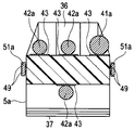
- the circuit board 5 is surface-bonded to the back surface of the image sensor 4 via a thermosetting adhesive or the like, a plurality of electronic components 35 and 36 are mounted, and a core wire of a plate-like block in which electronic components (not shown) are embedded.
- the connecting portion 5a and the outer conductor connecting portion 5b serving as a protruding portion extending so as to protrude rearward from the central portion of the proximal end of the core wire connecting portion 5a.
- the circuit board 5 as the hard board has a flexible printed circuit board (hereinafter referred to as FPC) 37 electrically connected to the lower surface of the core wire connecting portion 5a, and an inner lead extending from the front end side of the FPC 37.
- FPC flexible printed circuit board
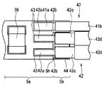
- a plurality of conductor lands 43 to which the core wire 41a of the power supply line 41 and the core wires 42a of the plurality of signal lines 42 are connected by solder are disposed on the front and back surfaces of the circuit board 5 behind the core wire connection portion 5a.
- At least one conductor land 43 and the outer skin 42d of the plurality of signal lines 42 are peeled in the extending direction along the longitudinal direction of the circuit board 5.
- One or a plurality of outer conductor lands 44 to which the outer diameter portion of the outer conductor 42c is connected are disposed.
- the circuit board 5 has the core wires 41a and 42a of the power supply line 41 and the signal line 42 for transmitting and receiving an imaging signal, a drive signal and the like extended from the composite cable 115, and are electrically connected to the conductor land 43 by solder.
- the outer diameter portion of the outer conductor 42c of the signal line 42 is electrically connected to the outer conductor land 44 by solder.
- the plurality of signal lines 42 here are coaxial cables.
- the plurality of signal lines 42 are arranged in the composite cable 115 together with the power supply line 41 in the insertion portion 102.
- the composite cable 115 has a configuration in which an outer shield 115 b is covered with a general shield 115 a such as a copper wire.
- the power supply line 41 has a configuration in which the core wire 41a is covered with an outer skin 41b formed of an insulating resin.
- a plurality of signal lines 42 that are coaxial lines are inserted into a resin-made dielectric 42b whose core wire 42a controls impedance, and a thin conductor covering, for example, the outer periphery of the dielectric 42b is braided to form GND.
- the above-described outer conductor 42c used is covered with an outer skin 42d made of an insulating resin.
- the power supply line 41 and the plurality of signal lines 42 When the power supply line 41 and the plurality of signal lines 42 are electrically connected to the imaging unit 1, the power supply line 41 and the plurality of signal lines 42 extend from the distal end of the composite cable 115, and the outer skins 41 b and 42 d are peeled off.
- the power supply line 41 is soldered to at least one of the conductor lands 43 on the upper surface side as viewed from the surface of the core wire connection portion 5 a of the circuit board 5 of the circuit board 5 of the imaging unit 1. Is electrically connected. At this time, as shown in FIG. 8, the power supply line 41 is connected to the conductor land 43 by peeling the core wire 41a so that the outer skin 41b overlaps the outer conductor connecting portion 5b.
- the plurality of signal lines 42 have respective core wires 42a on the front and back surfaces of the core wire connection portion 5a in the circuit board 5 of the imaging unit 1, here, the upper and lower surfaces as viewed toward the paper surface. It is electrically connected to a predetermined conductor land 43 by solder (see FIG. 7).
- the plurality of signal lines 42 are stripped so that the distal end position of the dielectric 42b is close to the base end of the core wire connection portion 5a so as not to overlap the core wire connection portion 5a.
- the core wire 42a is stripped and removed. Accordingly, since the signal line 42 can be connected in parallel to the laminated substrate 5a, it is possible to prevent the signal line 42 from bending in the vertical direction on the paper surface and increasing the outer shape of the imaging unit.
- the outer conductor 42c is cut so that the tip is located slightly behind the tip of the dielectric 42b so as not to be short-circuited with the core wire 42a, and covers the dielectric 42b.
- An outer peripheral portion as an outer diameter portion is electrically connected to a predetermined external conductor land 44 provided on the back surface by solder (see FIG. 8).
- the plurality of external conductor lands 44 provided for each signal line are collectively used for the same GND, and wide cable lands may be arranged on the upper and lower surfaces of the external conductor connecting portion 5b in this embodiment. .
- the circuit board 5 is integrally formed by a base material on which the core wire connection portion 5a and the outer conductor connection portion 5b are laminated, and one or a plurality, in this case, 2 on the front and back surfaces of the portion to become the core wire connection portion 5a
- a step of the outer conductor connecting portion 5b is formed by further stacking the sheets 5c.
- the dimensional difference ⁇ t between the outer diameter portion of the core wire 42a of the signal line 42 and the outer diameter portion of the outer conductor that is, the sum of the thickness of the dielectric of the signal line 42 and the thickness of the outer conductor is the sheet 5c.
- the thickness is approximately an integral multiple of.
- the dimensional difference ⁇ t is about twice the thickness of the sheet 5c, and the two sheets 5c are laminated to be predetermined in the inner diameter direction with respect to the core wire connecting portion 5a.
- the step of the outer conductor connecting portion 5b having the height dimension t1 is formed.
- the circuit board 5 to which the signal line 42 is connected is formed by combining one or a plurality of sheets 5c according to the dimensional difference ⁇ t between the outer diameter portion of the core wire 42a of the signal line 42 and the outer diameter portion of the outer conductor.
- a step is formed in the outer conductor connecting portion 5b having a predetermined height dimension t1 in the center direction with respect to the connecting portion 5a.
- the imaging unit 1 includes the core wire connection portion 5a to which the power supply line 41 and the core wires 41a and 42a of the plurality of signal lines 42 are connected to the circuit board 5, and the outline center direction with respect to the core wire connection portion 5a. And an outer conductor connecting portion 5b to which the outer conductors 42c of the plurality of signal lines 42 are connected.
- the conductor land 43 of the core wire connection part 5 a to which one signal line 42 is connected and the external conductor land 44 of the external conductor connection part 5 b are along the longitudinal direction of the circuit board 5. Arranged in the direction.
- the imaging unit 1 can connect the plurality of signal lines 42 to the circuit board 5 linearly along the longitudinal direction. That is, the plurality of signal lines 42 can connect the outer conductor 42c and the outer conductor land 44 of the outer conductor connecting portion 5b in a substantially straight state from the state where the core wire 42a is connected to the conductor land 43 of the core wire connecting portion 5a. .
- the imaging unit 1 configured as described above does not need to entangle the external conductors 42c of the plurality of signal lines 42 with a ground jumper line or the like as in the prior art, and is connected to the GND external conductor land 44.
- the outer cover 42d can be electrically connected in a state of being peeled off, the circuit board 5 can be shortened, and since the outer conductor 42c does not have a binding portion and does not swell in the outer diameter direction, the diameter can be reduced. .
- the outer conductor connecting portion 5b extending from the circuit board 5 which is a hard board to the base end side uses a space for routing each signal line 42 to a predetermined position of the laminated board 5a.
- the hard length of the circuit board 5 can be shortened without extending.
- the imaging unit 1 according to the present embodiment can be reduced in size in the configuration built in the distal end portion 110 of the insertion portion 102 of the endoscope 101, the distal end portion 110 is also reduced in size, and the insertion portion 102. It can be set as the structure which contributes to diameter reduction.
- the imaging unit 1 is provided with a step on the circuit board 5, so that the solder material used when soldering the core wires 41 a and 42 a of the power supply line 41 and the plurality of signal lines 42 to the conductor land 43 is affected by the surface tension. It is difficult to flow to the connection portion 5b side, and it is possible to prevent a short circuit with the external conductors 42c of the plurality of signal lines 42, and there is no need to make a space in the longitudinal direction of the insertion portion as in the prior art, and thus the advantage of shortening the hard length There is also.
- the imaging unit 1 may have various modified configurations described below. Of course, the various configurations described below can also be combined with each other.
- FIG. 10 is a cross-sectional view showing the configuration of the external conductor connecting portion of the circuit board of the imaging unit of the first modification.
- the imaging unit 1 matches the shape of the external conductor 42 c in a portion where the external conductor land 44 is connected to the external conductor connection portion 5 b of the circuit board 5.
- a concave portion 5d having an arcuate cross section may be formed.
- the imaging unit 1 has the concave portion 5d formed in the external conductor connecting portion 5b of the circuit board 5 and the external conductor land 44 is provided on the surface of the concave portion 5d. Soldering of the conductor 42c to the outer conductor land 44 is facilitated and the assemblability is improved.
- circuit board 5 here is also formed with a recess 5e having an arcuate cross section in which the power supply line 41 engages with the outer conductor connecting portion 5b. Therefore, positioning of the power supply line 41 to the circuit board 5 is facilitated.
- the depth dimension of the recess 5d is the sum (sum) of the respective thickness dimensions of the outer conductor land 44, the dielectric 42b of the signal line 42, and the outer conductor 42c, so that the outer conductor with respect to the core wire connecting part 5a. There is no need to provide a step in the connecting portion 5b.
- FIG. 11 is a side view showing the configuration of the circuit board to which the power supply line and the plurality of signal lines of the second modification are connected
- FIG. 12 is a cross-sectional view showing the configuration of the imaging unit along the line XII-XII in FIG. FIG.
- the imaging unit 1 may have a configuration in which a plurality of signal lines 42 are connected to both side surfaces of the external conductor connecting portion 5b of the circuit board 5.
- the imaging unit 1 includes the conductor land 43 or the external conductor land in which the core wire 42a or the external conductor 42c of the signal line 42 is connected to both side surfaces of the core wire connection portion 5a or the external conductor connection portion 5b of the circuit board 5. 44 is formed.
- the outer conductor connecting portion 5b here has a step in the side surface direction with respect to the core wire connecting portion 5a, and the signal lines 42 connected to both side surfaces of the circuit board 5 are arranged in the longitudinal direction. It can be connected linearly along.
- the imaging unit 1 having such a configuration can improve the design freedom of the circuit board 5 in addition to the above-described effects.
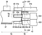
- FIG. 13 is a side view showing the configuration of the circuit board to which the power supply line and the plurality of signal lines of the third modification are connected
- FIG. 14 is a cross-sectional view showing the configuration of the imaging unit along the XIV-XIV line in FIG.
- FIG. 15 and FIG. 15 are side views showing a state before the outer conductor connecting portion is joined to the core wire connecting portion.
- the imaging unit 1 here has a configuration in which a plurality of signal lines 42 are connected to both side surfaces of the external conductor connecting portion 5 b of the circuit board 5, as in the second modification.
- the external conductor connection portion 5b is mounted separately from the core wire connection portion 5a of the circuit board 5.
- the circuit board 5 has a core-shaped connecting portion 5a formed with a rectangular recess 5f from the central portion of the base end surface toward the inside, and the outer conductor connecting portion 5b is connected to the core wire from the central portion of the distal end surface.
- a rectangular convex portion 5g similar to the concave portion 5f of the portion 5a is formed.
- the outer conductor connecting portion 5b is attached to the core wire connecting portion 5a by engaging the convex portion 5g of the outer conductor connecting portion 5b with the concave portion 5f of the core wire connecting portion 5a.
- the outer conductor connecting portion 5b and the core wire connecting portion 5a are fixed by an adhesive or the like.
- the core wire connecting portion 5a is provided with two electrical contacts 45 on both side portions on the lower side of the base end face.
- the outer conductor connecting portion 5b is provided with two electrical contacts 46 that are in contact with and electrically connected to the two electrical contacts 45 of the core wire connecting portion 5a on both sides of the lower end side of the base end surface of the distal end surface. Yes.
- the electrical contacts 45 and 46 in contact with each other are ensured to be electrically connected by fillet-like solder or the like.
- the electrical contacts 45 and 46 are electrically connected to the GND conductor, and are electrically connected to the external conductor land 44 via the internal wiring in the external conductor connecting portion 5b.
- the imaging unit 1 assembles a unit in which a plurality of signal lines 42 are connected in advance to the external conductor connection portion 5b on the circuit board 5, and then the core wire connection portion.
- the outer conductor connecting portion 5b can be attached and fixed to 5a, and the assemblability can be improved.
- the circuit board 5 is formed by separating the core wire connection portion 5a and the external conductor connection portion 5b, thereby forming a small external conductor connection portion 5b by dicing or the like from a block-shaped laminate as compared with an integrated configuration. There is no need to do this, and the manufacturing becomes easy.
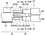
- FIG. 16 is a side view showing a configuration of a circuit board to which a plurality of signal lines according to a fourth modification are connected
- FIG. 17 is a cross-sectional view showing a configuration of an imaging unit along the line XVII-XVII in FIG. 18 is a cross-sectional view showing the configuration of the imaging unit along the line XVIII-XVIII in FIG. 16,
- FIG. 19 is a perspective view showing the configuration of a metal outer conductor connecting portion.
- a substantially plate-like external conductor connecting portion 51 formed of a conductor such as metal can be attached to the core wire connecting portion 5 a of the circuit board 5. It has become a separate structure.
- the circuit board 5 is provided with two electrical contacts 49 on one side here on both side surfaces of the core wire connecting portion 5a. As shown in FIG. The two arm portions 51a (see FIG. 19) are electrically connected by solder.
- the electrical contacts 49 provided in these core wire connection portions 5a are electrically connected to the GND conductor by internal wiring.
- the outer conductor 42c is electrically connected to the front and back surfaces of the plate-like portion 51b of the outer conductor connecting portion 51 directly by solder.
- the outer conductor connecting portion 51 has a structure in which two arm portions 51a are extended forward from both side portions on the front end side of the plate-like portion 51b.
- the imaging unit 1 has a plurality of signal lines 42 connected in advance to the external conductor connecting portion 51 in the circuit board 5 as in the third embodiment.
- the outer conductor connecting portion 5b can be attached and fixed to the core wire connecting portion 5a, and the assemblability can be improved.
- the outer conductor connecting portion 51 is mounted and fixed at a desired position of the core wire connecting portion 5a, the surface of the core wire connecting portion 5a to which the core wire 42a is connected and the outer conductor 42c are connected as described with reference to FIG.
- the surface of the external conductor connection portion 5b to be connected has a predetermined height.
- the imaging unit 1 since the external conductor connection portion 51 itself of the circuit board 5 is a conductor, the imaging unit 1 does not need to provide an external conductor land for electrically connecting the external conductor 42c of the signal line 42, and can be easily provided. Electrical connection with the core wire connecting portion 5a can be performed.
- FIG. 20 is a top view showing the configuration of a circuit board to which a plurality of signal lines of the fifth modification are connected
- FIG. 21 is a side view showing the configuration of a circuit board to which a plurality of signal lines are connected
- FIG. 22 is a cross-sectional view illustrating a configuration of an imaging unit along the line XXII-XXII in FIG.
- the imaging unit 1 here has external conductor lands 44 to which the external conductors 42 c of the plurality of signal lines 42 are connected to the front and back surfaces of the external conductor connection portion 5 b of the circuit board 5. Step portions 5h and 5i having notches or grooves are formed.
- the stepped portion 5i formed on the back surface of the outer conductor connecting portion 5b is formed so that the outer conductor connecting portion 5b has a concave cross section.
- the imaging unit 1 forms the step portions 5h and 5i on the front and back surfaces of the external conductor connection portion 5b of the circuit board 5, and by providing the external conductor land 44 on each surface of the step portions 5h and 5i.
- the positioning for connecting the signal line 42 is facilitated, the soldering of the outer conductor 42c to the outer conductor land 44 is facilitated, and the assemblability is improved.
- the imaging unit 1 here has stepped portions 5h and 5i on the front and back surfaces of the external conductor connecting portion 5b more easily than the configuration in which the semicircular concave portion 5d is formed as in the first modification. Since it can be formed, the workability is good.
- the depth dimension of the stepped portions 5h and 5i is the sum (sum) of the thickness dimensions of the outer conductor land 44, the dielectric 42b of the signal line 42, and the outer conductor 42c, so that the core wire connecting portion 5a.
- the imaging unit 1 of the embodiment and the modification described above exemplifies a so-called vertical-type imaging device 4, for example, so-called horizontal detection of photographic light refracted using a reflecting member such as a prism is used. It can also be applied to a stand-up type configuration.
- the endoscope 101 described above is exemplified as a so-called flexible mirror.
- the endoscope 101 is not limited to a rigid endoscope used for a surgical operation or the like, and is not limited to medical use, but may be any imaging unit 1 such as an industrial endoscope. This technique is applicable to an electronic endoscope equipped with
- the stated requirements can be deleted if the stated problem can be solved and the stated effect can be obtained.
- the structure thus constructed can be extracted as an invention.
Landscapes
- Physics & Mathematics (AREA)
- Health & Medical Sciences (AREA)
- Life Sciences & Earth Sciences (AREA)
- Engineering & Computer Science (AREA)
- Optics & Photonics (AREA)
- Surgery (AREA)
- Multimedia (AREA)
- Signal Processing (AREA)
- Biomedical Technology (AREA)
- General Health & Medical Sciences (AREA)
- Radiology & Medical Imaging (AREA)
- Nuclear Medicine, Radiotherapy & Molecular Imaging (AREA)
- Biophysics (AREA)
- Heart & Thoracic Surgery (AREA)
- Medical Informatics (AREA)
- Molecular Biology (AREA)
- Animal Behavior & Ethology (AREA)
- Pathology (AREA)
- Public Health (AREA)
- Veterinary Medicine (AREA)
- Astronomy & Astrophysics (AREA)
- General Physics & Mathematics (AREA)
- Endoscopes (AREA)
- Instruments For Viewing The Inside Of Hollow Bodies (AREA)
- Studio Devices (AREA)
Abstract
Description
撮像ユニット1は、図5に示すように、前方となる物体側から順に、レンズホルダ2、撮像素子ホルダ3、撮像素子4および回路基板5を有して主に構成されている。 Here, the
As shown in FIG. 5, the
撮像ユニット1は、以下に説明する種々の変形例の構成としてもよい。なお、以下に説明する各種変形例において、それぞれの構成を組み合わせることもできることは勿論である。 (Modification)
The
図10は、第1の変形例の撮像ユニットの回路基板の外部導体接続部の構成を示す断面図である。 (First modification)
FIG. 10 is a cross-sectional view showing the configuration of the external conductor connecting portion of the circuit board of the imaging unit of the first modification.
図11は、第2の変形例の電源線および複数の信号線が接続された回路基板の構成を示す側面図、図12は図11のXII-XII線に沿った撮像ユニットの構成を示す断面図である。 (Second modification)
11 is a side view showing the configuration of the circuit board to which the power supply line and the plurality of signal lines of the second modification are connected, and FIG. 12 is a cross-sectional view showing the configuration of the imaging unit along the line XII-XII in FIG. FIG.
図13は、第3の変形例の電源線および複数の信号線が接続された回路基板の構成を示す側面図、図14は図13のXIV-XIV線に沿った撮像ユニットの構成を示す断面図、図15は芯線接続部に外部導体接続部が接合される前の状態を示す側面図である。 (Third Modification)
FIG. 13 is a side view showing the configuration of the circuit board to which the power supply line and the plurality of signal lines of the third modification are connected, and FIG. 14 is a cross-sectional view showing the configuration of the imaging unit along the XIV-XIV line in FIG. FIG. 15 and FIG. 15 are side views showing a state before the outer conductor connecting portion is joined to the core wire connecting portion.
図16は、第4の変形例の複数の信号線が接続された回路基板の構成を示す側面図、図17は図16のXVII-XVII線に沿った撮像ユニットの構成を示す断面図、図18は図16のXVIII-XVIII線に沿った撮像ユニットの構成を示す断面図、図19は金属製の外部導体接続部の構成を示す斜視図である。 (Fourth modification)
16 is a side view showing a configuration of a circuit board to which a plurality of signal lines according to a fourth modification are connected, and FIG. 17 is a cross-sectional view showing a configuration of an imaging unit along the line XVII-XVII in FIG. 18 is a cross-sectional view showing the configuration of the imaging unit along the line XVIII-XVIII in FIG. 16, and FIG. 19 is a perspective view showing the configuration of a metal outer conductor connecting portion.
図20は、第5の変形例の複数の信号線が接続された回路基板の構成を示す上面図、図21は複数の信号線が接続された回路基板の構成を示す側面図、図22は図21のXXII-XXII線に沿った撮像ユニットの構成を示す断面図である。 (Fifth modification)
20 is a top view showing the configuration of a circuit board to which a plurality of signal lines of the fifth modification are connected, FIG. 21 is a side view showing the configuration of a circuit board to which a plurality of signal lines are connected, and FIG. FIG. 22 is a cross-sectional view illustrating a configuration of an imaging unit along the line XXII-XXII in FIG.
Claims (10)
- 被写体像を検出する撮像素子と、
前記撮像素子に電気的に接続した硬質基板と、
少なくとも1つ以上の同軸線を内蔵する信号ケーブルと、
を有する固体撮像装置において、
前記硬質基板は、前記同軸線の芯線が接続される芯線接続部を有する第1の面と、
前記同軸線の外部導体が接続される外部導体接続部を有し、前記第1の面と略平行な第2の面と、
を備え、
前記同軸線が前記硬質基板の前記第1および第2の面に対して略平行に接続されることを特徴とする固体撮像装置。 An image sensor for detecting a subject image;
A hard substrate electrically connected to the imaging device;
A signal cable containing at least one coaxial wire;
In a solid-state imaging device having
The hard substrate has a first surface having a core wire connecting portion to which the core wire of the coaxial line is connected;
An outer conductor connecting portion to which an outer conductor of the coaxial line is connected; a second surface substantially parallel to the first surface;
With
The solid-state imaging device, wherein the coaxial line is connected substantially parallel to the first and second surfaces of the hard substrate. - 前記外部導体接続部を有する第2の面は、前記芯線接続部を有する第1の面に対して外形中心方向に段差を有していることを特徴とする請求項1に記載の固体撮像装置。 2. The solid-state imaging device according to claim 1, wherein the second surface having the external conductor connection portion has a step in the center of the outer shape with respect to the first surface having the core wire connection portion. .
- 前記段差の高さ寸法は、前記同軸線の前記芯線の外径部と前記外部導体の外径部の寸法差と略同一であることを特徴とする請求項2に記載の固体撮像装置。 3. The solid-state imaging device according to claim 2, wherein a height dimension of the step is substantially the same as a dimensional difference between an outer diameter part of the core wire and an outer diameter part of the outer conductor of the coaxial line.
- 前記第1の面と前記第2の面における前記段差は、シート状基板の積層枚数を変えることによって形成されていることを特徴とする請求項2または請求項3に記載の固体撮像装置。 4. The solid-state imaging device according to claim 2, wherein the step between the first surface and the second surface is formed by changing the number of stacked sheet-like substrates.
- 前記同軸線の前記芯線の外径部と前記外部導体の外径部の寸法差は、前記シート状基板の略整数倍であることを特徴とする請求項4に記載の固体撮像装置。 5. The solid-state imaging device according to claim 4, wherein a dimensional difference between the outer diameter portion of the core wire of the coaxial line and the outer diameter portion of the outer conductor is substantially an integer multiple of the sheet-like substrate.
- 前記同軸線は、前記硬質基板の表裏面または側面に接続されていることを特徴とする請求項1から請求項5のいずれか1項に記載の固体撮像装置。 The solid-state imaging device according to any one of claims 1 to 5, wherein the coaxial line is connected to front and back surfaces or side surfaces of the hard substrate.
- 前記芯線接続部に装着自在な前記外部導体接続部を有していることを特徴とする請求項1から請求項6のいずれか1項に記載の固体撮像装置。 The solid-state imaging device according to any one of claims 1 to 6, further comprising the outer conductor connecting portion that is attachable to the core wire connecting portion.
- 前記芯線接続部には、前記同軸線の外部導体の外周部が電気的に接続される外部導体ランドが少なくとも1つ以上配設されていることを特徴とする請求項1から請求項7のいずれか1項に記載の固体撮像装置。 8. The core wire connecting portion is provided with at least one or more external conductor lands to which an outer peripheral portion of the outer conductor of the coaxial line is electrically connected. The solid-state imaging device according to claim 1.
- 前記外部導体接続部は、導電体によって形成されていることを特徴とする請求項1から請求項7のいずれか1項に記載の固体撮像装置。 The solid-state imaging device according to any one of claims 1 to 7, wherein the outer conductor connecting portion is formed of a conductor.
- 請求項1から請求項9のいずれか1項に記載の固体撮像装置と、
前記撮像ユニットが先端部内に内蔵された挿入部と、
を具備し、
前記信号ケーブルが前記挿入部の長手方向に略平行に配置されていることを特徴とする電子内視鏡。 A solid-state imaging device according to any one of claims 1 to 9,
An insertion part in which the imaging unit is built in the tip part;
Comprising
An electronic endoscope, wherein the signal cable is disposed substantially parallel to a longitudinal direction of the insertion portion.
Priority Applications (4)
| Application Number | Priority Date | Filing Date | Title |
|---|---|---|---|
| JP2016506011A JP5945653B1 (en) | 2014-10-20 | 2015-08-18 | Solid-state imaging device and electronic endoscope provided with the solid-state imaging device |
| EP15853210.1A EP3103381A4 (en) | 2014-10-20 | 2015-08-18 | Solid-state imaging device and electronic endoscope provided with solid-state imaging device |
| CN201580011565.2A CN106061365A (en) | 2014-10-20 | 2015-08-18 | Solid-state imaging device and electronic endoscope provided with solid-state imaging device |
| US15/251,001 US20160367122A1 (en) | 2014-10-20 | 2016-08-30 | Solid-state image pickup apparatus and electronic endoscope including solid-state image pickup apparatus |
Applications Claiming Priority (2)
| Application Number | Priority Date | Filing Date | Title |
|---|---|---|---|
| JP2014-213605 | 2014-10-20 | ||
| JP2014213605 | 2014-10-20 |
Related Child Applications (1)
| Application Number | Title | Priority Date | Filing Date |
|---|---|---|---|
| US15/251,001 Continuation US20160367122A1 (en) | 2014-10-20 | 2016-08-30 | Solid-state image pickup apparatus and electronic endoscope including solid-state image pickup apparatus |
Publications (1)
| Publication Number | Publication Date |
|---|---|
| WO2016063603A1 true WO2016063603A1 (en) | 2016-04-28 |
Family
ID=55760651
Family Applications (1)
| Application Number | Title | Priority Date | Filing Date |
|---|---|---|---|
| PCT/JP2015/073112 WO2016063603A1 (en) | 2014-10-20 | 2015-08-18 | Solid-state imaging device and electronic endoscope provided with solid-state imaging device |
Country Status (5)
| Country | Link |
|---|---|
| US (1) | US20160367122A1 (en) |
| EP (1) | EP3103381A4 (en) |
| JP (1) | JP5945653B1 (en) |
| CN (1) | CN106061365A (en) |
| WO (1) | WO2016063603A1 (en) |
Cited By (5)
| Publication number | Priority date | Publication date | Assignee | Title |
|---|---|---|---|---|
| WO2018003510A1 (en) * | 2016-06-29 | 2018-01-04 | オリンパス株式会社 | Imaging unit and endoscope |
| WO2018078766A1 (en) * | 2016-10-27 | 2018-05-03 | オリンパス株式会社 | Imaging unit, endoscope, and imaging unit production method |
| WO2018158897A1 (en) * | 2017-03-01 | 2018-09-07 | オリンパス株式会社 | Cable mounting structure and endoscope |
| JPWO2018078767A1 (en) * | 2016-10-27 | 2019-06-24 | オリンパス株式会社 | Endoscope |
| JP2019118762A (en) * | 2018-01-11 | 2019-07-22 | オリンパス株式会社 | Board unit of endoscope |
Families Citing this family (402)
| Publication number | Priority date | Publication date | Assignee | Title |
|---|---|---|---|---|
| US9060770B2 (en) | 2003-05-20 | 2015-06-23 | Ethicon Endo-Surgery, Inc. | Robotically-driven surgical instrument with E-beam driver |
| US20070084897A1 (en) | 2003-05-20 | 2007-04-19 | Shelton Frederick E Iv | Articulating surgical stapling instrument incorporating a two-piece e-beam firing mechanism |
| US11890012B2 (en) | 2004-07-28 | 2024-02-06 | Cilag Gmbh International | Staple cartridge comprising cartridge body and attached support |
| US8215531B2 (en) | 2004-07-28 | 2012-07-10 | Ethicon Endo-Surgery, Inc. | Surgical stapling instrument having a medical substance dispenser |
| US7934630B2 (en) | 2005-08-31 | 2011-05-03 | Ethicon Endo-Surgery, Inc. | Staple cartridges for forming staples having differing formed staple heights |
| US9237891B2 (en) | 2005-08-31 | 2016-01-19 | Ethicon Endo-Surgery, Inc. | Robotically-controlled surgical stapling devices that produce formed staples having different lengths |
| US10159482B2 (en) | 2005-08-31 | 2018-12-25 | Ethicon Llc | Fastener cartridge assembly comprising a fixed anvil and different staple heights |
| US11246590B2 (en) | 2005-08-31 | 2022-02-15 | Cilag Gmbh International | Staple cartridge including staple drivers having different unfired heights |
| US7669746B2 (en) | 2005-08-31 | 2010-03-02 | Ethicon Endo-Surgery, Inc. | Staple cartridges for forming staples having differing formed staple heights |
| US11484312B2 (en) | 2005-08-31 | 2022-11-01 | Cilag Gmbh International | Staple cartridge comprising a staple driver arrangement |
| US20070106317A1 (en) | 2005-11-09 | 2007-05-10 | Shelton Frederick E Iv | Hydraulically and electrically actuated articulation joints for surgical instruments |
| US20120292367A1 (en) | 2006-01-31 | 2012-11-22 | Ethicon Endo-Surgery, Inc. | Robotically-controlled end effector |
| US7845537B2 (en) | 2006-01-31 | 2010-12-07 | Ethicon Endo-Surgery, Inc. | Surgical instrument having recording capabilities |
| US8820603B2 (en) | 2006-01-31 | 2014-09-02 | Ethicon Endo-Surgery, Inc. | Accessing data stored in a memory of a surgical instrument |
| US11278279B2 (en) | 2006-01-31 | 2022-03-22 | Cilag Gmbh International | Surgical instrument assembly |
| US20110290856A1 (en) | 2006-01-31 | 2011-12-01 | Ethicon Endo-Surgery, Inc. | Robotically-controlled surgical instrument with force-feedback capabilities |
| US11793518B2 (en) | 2006-01-31 | 2023-10-24 | Cilag Gmbh International | Powered surgical instruments with firing system lockout arrangements |
| US8186555B2 (en) | 2006-01-31 | 2012-05-29 | Ethicon Endo-Surgery, Inc. | Motor-driven surgical cutting and fastening instrument with mechanical closure system |
| US8708213B2 (en) | 2006-01-31 | 2014-04-29 | Ethicon Endo-Surgery, Inc. | Surgical instrument having a feedback system |
| US20110024477A1 (en) | 2009-02-06 | 2011-02-03 | Hall Steven G | Driven Surgical Stapler Improvements |
| US11224427B2 (en) | 2006-01-31 | 2022-01-18 | Cilag Gmbh International | Surgical stapling system including a console and retraction assembly |
| US7753904B2 (en) | 2006-01-31 | 2010-07-13 | Ethicon Endo-Surgery, Inc. | Endoscopic surgical instrument with a handle that can articulate with respect to the shaft |
| US8992422B2 (en) | 2006-03-23 | 2015-03-31 | Ethicon Endo-Surgery, Inc. | Robotically-controlled endoscopic accessory channel |
| US8322455B2 (en) | 2006-06-27 | 2012-12-04 | Ethicon Endo-Surgery, Inc. | Manually driven surgical cutting and fastening instrument |
| US10568652B2 (en) | 2006-09-29 | 2020-02-25 | Ethicon Llc | Surgical staples having attached drivers of different heights and stapling instruments for deploying the same |
| US8220690B2 (en) | 2006-09-29 | 2012-07-17 | Ethicon Endo-Surgery, Inc. | Connected surgical staples and stapling instruments for deploying the same |
| US11980366B2 (en) | 2006-10-03 | 2024-05-14 | Cilag Gmbh International | Surgical instrument |
| US11291441B2 (en) | 2007-01-10 | 2022-04-05 | Cilag Gmbh International | Surgical instrument with wireless communication between control unit and remote sensor |
| US8652120B2 (en) | 2007-01-10 | 2014-02-18 | Ethicon Endo-Surgery, Inc. | Surgical instrument with wireless communication between control unit and sensor transponders |
| US8684253B2 (en) | 2007-01-10 | 2014-04-01 | Ethicon Endo-Surgery, Inc. | Surgical instrument with wireless communication between a control unit of a robotic system and remote sensor |
| US8540128B2 (en) | 2007-01-11 | 2013-09-24 | Ethicon Endo-Surgery, Inc. | Surgical stapling device with a curved end effector |
| US11039836B2 (en) | 2007-01-11 | 2021-06-22 | Cilag Gmbh International | Staple cartridge for use with a surgical stapling instrument |
| US7669747B2 (en) | 2007-03-15 | 2010-03-02 | Ethicon Endo-Surgery, Inc. | Washer for use with a surgical stapling instrument |
| US8893946B2 (en) | 2007-03-28 | 2014-11-25 | Ethicon Endo-Surgery, Inc. | Laparoscopic tissue thickness and clamp load measuring devices |
| US8931682B2 (en) | 2007-06-04 | 2015-01-13 | Ethicon Endo-Surgery, Inc. | Robotically-controlled shaft based rotary drive systems for surgical instruments |
| US11857181B2 (en) | 2007-06-04 | 2024-01-02 | Cilag Gmbh International | Robotically-controlled shaft based rotary drive systems for surgical instruments |
| US7753245B2 (en) | 2007-06-22 | 2010-07-13 | Ethicon Endo-Surgery, Inc. | Surgical stapling instruments |
| US11849941B2 (en) | 2007-06-29 | 2023-12-26 | Cilag Gmbh International | Staple cartridge having staple cavities extending at a transverse angle relative to a longitudinal cartridge axis |
| US7819298B2 (en) | 2008-02-14 | 2010-10-26 | Ethicon Endo-Surgery, Inc. | Surgical stapling apparatus with control features operable with one hand |
| US8758391B2 (en) | 2008-02-14 | 2014-06-24 | Ethicon Endo-Surgery, Inc. | Interchangeable tools for surgical instruments |
| US9179912B2 (en) | 2008-02-14 | 2015-11-10 | Ethicon Endo-Surgery, Inc. | Robotically-controlled motorized surgical cutting and fastening instrument |
| US7866527B2 (en) | 2008-02-14 | 2011-01-11 | Ethicon Endo-Surgery, Inc. | Surgical stapling apparatus with interlockable firing system |
| US8636736B2 (en) | 2008-02-14 | 2014-01-28 | Ethicon Endo-Surgery, Inc. | Motorized surgical cutting and fastening instrument |
| US11986183B2 (en) | 2008-02-14 | 2024-05-21 | Cilag Gmbh International | Surgical cutting and fastening instrument comprising a plurality of sensors to measure an electrical parameter |
| BRPI0901282A2 (en) | 2008-02-14 | 2009-11-17 | Ethicon Endo Surgery Inc | surgical cutting and fixation instrument with rf electrodes |
| US8573465B2 (en) | 2008-02-14 | 2013-11-05 | Ethicon Endo-Surgery, Inc. | Robotically-controlled surgical end effector system with rotary actuated closure systems |
| US11272927B2 (en) | 2008-02-15 | 2022-03-15 | Cilag Gmbh International | Layer arrangements for surgical staple cartridges |
| US10136890B2 (en) | 2010-09-30 | 2018-11-27 | Ethicon Llc | Staple cartridge comprising a variable thickness compressible portion |
| US9770245B2 (en) | 2008-02-15 | 2017-09-26 | Ethicon Llc | Layer arrangements for surgical staple cartridges |
| US9005230B2 (en) | 2008-09-23 | 2015-04-14 | Ethicon Endo-Surgery, Inc. | Motorized surgical instrument |
| US9386983B2 (en) | 2008-09-23 | 2016-07-12 | Ethicon Endo-Surgery, Llc | Robotically-controlled motorized surgical instrument |
| US11648005B2 (en) | 2008-09-23 | 2023-05-16 | Cilag Gmbh International | Robotically-controlled motorized surgical instrument with an end effector |
| US8210411B2 (en) | 2008-09-23 | 2012-07-03 | Ethicon Endo-Surgery, Inc. | Motor-driven surgical cutting instrument |
| US8608045B2 (en) | 2008-10-10 | 2013-12-17 | Ethicon Endo-Sugery, Inc. | Powered surgical cutting and stapling apparatus with manually retractable firing system |
| US8517239B2 (en) | 2009-02-05 | 2013-08-27 | Ethicon Endo-Surgery, Inc. | Surgical stapling instrument comprising a magnetic element driver |
| WO2010090940A1 (en) | 2009-02-06 | 2010-08-12 | Ethicon Endo-Surgery, Inc. | Driven surgical stapler improvements |
| US8444036B2 (en) | 2009-02-06 | 2013-05-21 | Ethicon Endo-Surgery, Inc. | Motor driven surgical fastener device with mechanisms for adjusting a tissue gap within the end effector |
| US8851354B2 (en) | 2009-12-24 | 2014-10-07 | Ethicon Endo-Surgery, Inc. | Surgical cutting instrument that analyzes tissue thickness |
| US8220688B2 (en) | 2009-12-24 | 2012-07-17 | Ethicon Endo-Surgery, Inc. | Motor-driven surgical cutting instrument with electric actuator directional control assembly |
| US8783543B2 (en) | 2010-07-30 | 2014-07-22 | Ethicon Endo-Surgery, Inc. | Tissue acquisition arrangements and methods for surgical stapling devices |
| US9517063B2 (en) | 2012-03-28 | 2016-12-13 | Ethicon Endo-Surgery, Llc | Movable member for use with a tissue thickness compensator |
| US11925354B2 (en) | 2010-09-30 | 2024-03-12 | Cilag Gmbh International | Staple cartridge comprising staples positioned within a compressible portion thereof |
| US11812965B2 (en) | 2010-09-30 | 2023-11-14 | Cilag Gmbh International | Layer of material for a surgical end effector |
| US9211120B2 (en) | 2011-04-29 | 2015-12-15 | Ethicon Endo-Surgery, Inc. | Tissue thickness compensator comprising a plurality of medicaments |
| US9364233B2 (en) | 2010-09-30 | 2016-06-14 | Ethicon Endo-Surgery, Llc | Tissue thickness compensators for circular surgical staplers |
| US11298125B2 (en) | 2010-09-30 | 2022-04-12 | Cilag Gmbh International | Tissue stapler having a thickness compensator |
| US9320523B2 (en) | 2012-03-28 | 2016-04-26 | Ethicon Endo-Surgery, Llc | Tissue thickness compensator comprising tissue ingrowth features |
| US10945731B2 (en) | 2010-09-30 | 2021-03-16 | Ethicon Llc | Tissue thickness compensator comprising controlled release and expansion |
| US9788834B2 (en) | 2010-09-30 | 2017-10-17 | Ethicon Llc | Layer comprising deployable attachment members |
| US9629814B2 (en) | 2010-09-30 | 2017-04-25 | Ethicon Endo-Surgery, Llc | Tissue thickness compensator configured to redistribute compressive forces |
| US8695866B2 (en) | 2010-10-01 | 2014-04-15 | Ethicon Endo-Surgery, Inc. | Surgical instrument having a power control circuit |
| JP6026509B2 (en) | 2011-04-29 | 2016-11-16 | エシコン・エンド−サージェリィ・インコーポレイテッドEthicon Endo−Surgery,Inc. | Staple cartridge including staples disposed within a compressible portion of the staple cartridge itself |
| US11207064B2 (en) | 2011-05-27 | 2021-12-28 | Cilag Gmbh International | Automated end effector component reloading system for use with a robotic system |
| US9072535B2 (en) | 2011-05-27 | 2015-07-07 | Ethicon Endo-Surgery, Inc. | Surgical stapling instruments with rotatable staple deployment arrangements |
| US9044230B2 (en) | 2012-02-13 | 2015-06-02 | Ethicon Endo-Surgery, Inc. | Surgical cutting and fastening instrument with apparatus for determining cartridge and firing motion status |
| JP6305979B2 (en) | 2012-03-28 | 2018-04-04 | エシコン・エンド−サージェリィ・インコーポレイテッドEthicon Endo−Surgery,Inc. | Tissue thickness compensator with multiple layers |
| MX350846B (en) | 2012-03-28 | 2017-09-22 | Ethicon Endo Surgery Inc | Tissue thickness compensator comprising capsules defining a low pressure environment. |
| JP6224070B2 (en) | 2012-03-28 | 2017-11-01 | エシコン・エンド−サージェリィ・インコーポレイテッドEthicon Endo−Surgery,Inc. | Retainer assembly including tissue thickness compensator |
| US9101358B2 (en) | 2012-06-15 | 2015-08-11 | Ethicon Endo-Surgery, Inc. | Articulatable surgical instrument comprising a firing drive |
| BR112014032740A2 (en) | 2012-06-28 | 2020-02-27 | Ethicon Endo Surgery Inc | empty clip cartridge lock |
| US11278284B2 (en) | 2012-06-28 | 2022-03-22 | Cilag Gmbh International | Rotary drive arrangements for surgical instruments |
| BR112014032776B1 (en) | 2012-06-28 | 2021-09-08 | Ethicon Endo-Surgery, Inc | SURGICAL INSTRUMENT SYSTEM AND SURGICAL KIT FOR USE WITH A SURGICAL INSTRUMENT SYSTEM |
| US9282974B2 (en) | 2012-06-28 | 2016-03-15 | Ethicon Endo-Surgery, Llc | Empty clip cartridge lockout |
| US9289256B2 (en) | 2012-06-28 | 2016-03-22 | Ethicon Endo-Surgery, Llc | Surgical end effectors having angled tissue-contacting surfaces |
| US9204879B2 (en) | 2012-06-28 | 2015-12-08 | Ethicon Endo-Surgery, Inc. | Flexible drive member |
| US9408606B2 (en) | 2012-06-28 | 2016-08-09 | Ethicon Endo-Surgery, Llc | Robotically powered surgical device with manually-actuatable reversing system |
| US20140001231A1 (en) | 2012-06-28 | 2014-01-02 | Ethicon Endo-Surgery, Inc. | Firing system lockout arrangements for surgical instruments |
| MX364729B (en) | 2013-03-01 | 2019-05-06 | Ethicon Endo Surgery Inc | Surgical instrument with a soft stop. |
| RU2672520C2 (en) | 2013-03-01 | 2018-11-15 | Этикон Эндо-Серджери, Инк. | Hingedly turnable surgical instruments with conducting ways for signal transfer |
| US9629629B2 (en) | 2013-03-14 | 2017-04-25 | Ethicon Endo-Surgey, LLC | Control systems for surgical instruments |
| US9888919B2 (en) | 2013-03-14 | 2018-02-13 | Ethicon Llc | Method and system for operating a surgical instrument |
| BR112015026109B1 (en) | 2013-04-16 | 2022-02-22 | Ethicon Endo-Surgery, Inc | surgical instrument |
| US10149680B2 (en) | 2013-04-16 | 2018-12-11 | Ethicon Llc | Surgical instrument comprising a gap setting system |
| BR112016003329B1 (en) | 2013-08-23 | 2021-12-21 | Ethicon Endo-Surgery, Llc | SURGICAL INSTRUMENT |
| US20150053743A1 (en) | 2013-08-23 | 2015-02-26 | Ethicon Endo-Surgery, Inc. | Error detection arrangements for surgical instrument assemblies |
| US9962161B2 (en) | 2014-02-12 | 2018-05-08 | Ethicon Llc | Deliverable surgical instrument |
| BR112016019387B1 (en) | 2014-02-24 | 2022-11-29 | Ethicon Endo-Surgery, Llc | SURGICAL INSTRUMENT SYSTEM AND FASTENER CARTRIDGE FOR USE WITH A SURGICAL FIXING INSTRUMENT |
| US20150272582A1 (en) | 2014-03-26 | 2015-10-01 | Ethicon Endo-Surgery, Inc. | Power management control systems for surgical instruments |
| US9826977B2 (en) | 2014-03-26 | 2017-11-28 | Ethicon Llc | Sterilization verification circuit |
| US20150272557A1 (en) | 2014-03-26 | 2015-10-01 | Ethicon Endo-Surgery, Inc. | Modular surgical instrument system |
| BR112016021943B1 (en) | 2014-03-26 | 2022-06-14 | Ethicon Endo-Surgery, Llc | SURGICAL INSTRUMENT FOR USE BY AN OPERATOR IN A SURGICAL PROCEDURE |
| CN106456159B (en) | 2014-04-16 | 2019-03-08 | 伊西康内外科有限责任公司 | Fastener cartridge assembly and nail retainer lid arragement construction |
| US20150297225A1 (en) | 2014-04-16 | 2015-10-22 | Ethicon Endo-Surgery, Inc. | Fastener cartridges including extensions having different configurations |
| CN106456176B (en) | 2014-04-16 | 2019-06-28 | 伊西康内外科有限责任公司 | Fastener cartridge including the extension with various configuration |
| US9844369B2 (en) | 2014-04-16 | 2017-12-19 | Ethicon Llc | Surgical end effectors with firing element monitoring arrangements |
| BR112016023825B1 (en) | 2014-04-16 | 2022-08-02 | Ethicon Endo-Surgery, Llc | STAPLE CARTRIDGE FOR USE WITH A SURGICAL STAPLER AND STAPLE CARTRIDGE FOR USE WITH A SURGICAL INSTRUMENT |
| US9801628B2 (en) | 2014-09-26 | 2017-10-31 | Ethicon Llc | Surgical staple and driver arrangements for staple cartridges |
| BR112017004361B1 (en) | 2014-09-05 | 2023-04-11 | Ethicon Llc | ELECTRONIC SYSTEM FOR A SURGICAL INSTRUMENT |
| US11311294B2 (en) | 2014-09-05 | 2022-04-26 | Cilag Gmbh International | Powered medical device including measurement of closure state of jaws |
| US9724094B2 (en) | 2014-09-05 | 2017-08-08 | Ethicon Llc | Adjunct with integrated sensors to quantify tissue compression |
| US10105142B2 (en) | 2014-09-18 | 2018-10-23 | Ethicon Llc | Surgical stapler with plurality of cutting elements |
| US11523821B2 (en) | 2014-09-26 | 2022-12-13 | Cilag Gmbh International | Method for creating a flexible staple line |
| JP6648119B2 (en) | 2014-09-26 | 2020-02-14 | エシコン エルエルシーEthicon LLC | Surgical stapling buttress and accessory materials |
| US10076325B2 (en) | 2014-10-13 | 2018-09-18 | Ethicon Llc | Surgical stapling apparatus comprising a tissue stop |
| US9924944B2 (en) | 2014-10-16 | 2018-03-27 | Ethicon Llc | Staple cartridge comprising an adjunct material |
| US11141153B2 (en) | 2014-10-29 | 2021-10-12 | Cilag Gmbh International | Staple cartridges comprising driver arrangements |
| US10517594B2 (en) | 2014-10-29 | 2019-12-31 | Ethicon Llc | Cartridge assemblies for surgical staplers |
| US9844376B2 (en) | 2014-11-06 | 2017-12-19 | Ethicon Llc | Staple cartridge comprising a releasable adjunct material |
| US10736636B2 (en) | 2014-12-10 | 2020-08-11 | Ethicon Llc | Articulatable surgical instrument system |
| US9844375B2 (en) | 2014-12-18 | 2017-12-19 | Ethicon Llc | Drive arrangements for articulatable surgical instruments |
| US10085748B2 (en) | 2014-12-18 | 2018-10-02 | Ethicon Llc | Locking arrangements for detachable shaft assemblies with articulatable surgical end effectors |
| BR112017012996B1 (en) | 2014-12-18 | 2022-11-08 | Ethicon Llc | SURGICAL INSTRUMENT WITH AN ANvil WHICH IS SELECTIVELY MOVABLE ABOUT AN IMMOVABLE GEOMETRIC AXIS DIFFERENT FROM A STAPLE CARTRIDGE |
| US10188385B2 (en) | 2014-12-18 | 2019-01-29 | Ethicon Llc | Surgical instrument system comprising lockable systems |
| US9987000B2 (en) | 2014-12-18 | 2018-06-05 | Ethicon Llc | Surgical instrument assembly comprising a flexible articulation system |
| US10245027B2 (en) | 2014-12-18 | 2019-04-02 | Ethicon Llc | Surgical instrument with an anvil that is selectively movable about a discrete non-movable axis relative to a staple cartridge |
| US9844374B2 (en) | 2014-12-18 | 2017-12-19 | Ethicon Llc | Surgical instrument systems comprising an articulatable end effector and means for adjusting the firing stroke of a firing member |
| US10180463B2 (en) | 2015-02-27 | 2019-01-15 | Ethicon Llc | Surgical apparatus configured to assess whether a performance parameter of the surgical apparatus is within an acceptable performance band |
| US10045779B2 (en) | 2015-02-27 | 2018-08-14 | Ethicon Llc | Surgical instrument system comprising an inspection station |
| US11154301B2 (en) | 2015-02-27 | 2021-10-26 | Cilag Gmbh International | Modular stapling assembly |
| US9993248B2 (en) | 2015-03-06 | 2018-06-12 | Ethicon Endo-Surgery, Llc | Smart sensors with local signal processing |
| US9808246B2 (en) | 2015-03-06 | 2017-11-07 | Ethicon Endo-Surgery, Llc | Method of operating a powered surgical instrument |
| US10441279B2 (en) | 2015-03-06 | 2019-10-15 | Ethicon Llc | Multiple level thresholds to modify operation of powered surgical instruments |
| US10687806B2 (en) | 2015-03-06 | 2020-06-23 | Ethicon Llc | Adaptive tissue compression techniques to adjust closure rates for multiple tissue types |
| US9901342B2 (en) | 2015-03-06 | 2018-02-27 | Ethicon Endo-Surgery, Llc | Signal and power communication system positioned on a rotatable shaft |
| JP2020121162A (en) | 2015-03-06 | 2020-08-13 | エシコン エルエルシーEthicon LLC | Time dependent evaluation of sensor data to determine stability element, creep element and viscoelastic element of measurement |
| US10052044B2 (en) | 2015-03-06 | 2018-08-21 | Ethicon Llc | Time dependent evaluation of sensor data to determine stability, creep, and viscoelastic elements of measures |
| US9924961B2 (en) | 2015-03-06 | 2018-03-27 | Ethicon Endo-Surgery, Llc | Interactive feedback system for powered surgical instruments |
| US10617412B2 (en) | 2015-03-06 | 2020-04-14 | Ethicon Llc | System for detecting the mis-insertion of a staple cartridge into a surgical stapler |
| US10245033B2 (en) | 2015-03-06 | 2019-04-02 | Ethicon Llc | Surgical instrument comprising a lockable battery housing |
| US10390825B2 (en) | 2015-03-31 | 2019-08-27 | Ethicon Llc | Surgical instrument with progressive rotary drive systems |
| US10835249B2 (en) | 2015-08-17 | 2020-11-17 | Ethicon Llc | Implantable layers for a surgical instrument |
| US10327769B2 (en) | 2015-09-23 | 2019-06-25 | Ethicon Llc | Surgical stapler having motor control based on a drive system component |
| US10105139B2 (en) | 2015-09-23 | 2018-10-23 | Ethicon Llc | Surgical stapler having downstream current-based motor control |
| US10363036B2 (en) | 2015-09-23 | 2019-07-30 | Ethicon Llc | Surgical stapler having force-based motor control |
| US10238386B2 (en) | 2015-09-23 | 2019-03-26 | Ethicon Llc | Surgical stapler having motor control based on an electrical parameter related to a motor current |
| US10299878B2 (en) | 2015-09-25 | 2019-05-28 | Ethicon Llc | Implantable adjunct systems for determining adjunct skew |
| US11890015B2 (en) | 2015-09-30 | 2024-02-06 | Cilag Gmbh International | Compressible adjunct with crossing spacer fibers |
| US10980539B2 (en) | 2015-09-30 | 2021-04-20 | Ethicon Llc | Implantable adjunct comprising bonded layers |
| US10736633B2 (en) | 2015-09-30 | 2020-08-11 | Ethicon Llc | Compressible adjunct with looping members |
| US11690623B2 (en) | 2015-09-30 | 2023-07-04 | Cilag Gmbh International | Method for applying an implantable layer to a fastener cartridge |
| US10368865B2 (en) | 2015-12-30 | 2019-08-06 | Ethicon Llc | Mechanisms for compensating for drivetrain failure in powered surgical instruments |
| US10292704B2 (en) | 2015-12-30 | 2019-05-21 | Ethicon Llc | Mechanisms for compensating for battery pack failure in powered surgical instruments |
| US10265068B2 (en) | 2015-12-30 | 2019-04-23 | Ethicon Llc | Surgical instruments with separable motors and motor control circuits |
| US10588625B2 (en) | 2016-02-09 | 2020-03-17 | Ethicon Llc | Articulatable surgical instruments with off-axis firing beam arrangements |
| JP6911054B2 (en) | 2016-02-09 | 2021-07-28 | エシコン エルエルシーEthicon LLC | Surgical instruments with asymmetric joint composition |
| US11213293B2 (en) | 2016-02-09 | 2022-01-04 | Cilag Gmbh International | Articulatable surgical instruments with single articulation link arrangements |
| US10258331B2 (en) | 2016-02-12 | 2019-04-16 | Ethicon Llc | Mechanisms for compensating for drivetrain failure in powered surgical instruments |
| US11224426B2 (en) | 2016-02-12 | 2022-01-18 | Cilag Gmbh International | Mechanisms for compensating for drivetrain failure in powered surgical instruments |
| US10448948B2 (en) | 2016-02-12 | 2019-10-22 | Ethicon Llc | Mechanisms for compensating for drivetrain failure in powered surgical instruments |
| US10617413B2 (en) | 2016-04-01 | 2020-04-14 | Ethicon Llc | Closure system arrangements for surgical cutting and stapling devices with separate and distinct firing shafts |
| US10314582B2 (en) | 2016-04-01 | 2019-06-11 | Ethicon Llc | Surgical instrument comprising a shifting mechanism |
| US10335145B2 (en) | 2016-04-15 | 2019-07-02 | Ethicon Llc | Modular surgical instrument with configurable operating mode |
| US10405859B2 (en) | 2016-04-15 | 2019-09-10 | Ethicon Llc | Surgical instrument with adjustable stop/start control during a firing motion |
| US10492783B2 (en) | 2016-04-15 | 2019-12-03 | Ethicon, Llc | Surgical instrument with improved stop/start control during a firing motion |
| US10456137B2 (en) | 2016-04-15 | 2019-10-29 | Ethicon Llc | Staple formation detection mechanisms |
| US10828028B2 (en) | 2016-04-15 | 2020-11-10 | Ethicon Llc | Surgical instrument with multiple program responses during a firing motion |
| US11179150B2 (en) | 2016-04-15 | 2021-11-23 | Cilag Gmbh International | Systems and methods for controlling a surgical stapling and cutting instrument |
| US10426467B2 (en) | 2016-04-15 | 2019-10-01 | Ethicon Llc | Surgical instrument with detection sensors |
| US11607239B2 (en) | 2016-04-15 | 2023-03-21 | Cilag Gmbh International | Systems and methods for controlling a surgical stapling and cutting instrument |
| US10357247B2 (en) | 2016-04-15 | 2019-07-23 | Ethicon Llc | Surgical instrument with multiple program responses during a firing motion |
| US10363037B2 (en) | 2016-04-18 | 2019-07-30 | Ethicon Llc | Surgical instrument system comprising a magnetic lockout |
| US20170296173A1 (en) | 2016-04-18 | 2017-10-19 | Ethicon Endo-Surgery, Llc | Method for operating a surgical instrument |
| US11317917B2 (en) | 2016-04-18 | 2022-05-03 | Cilag Gmbh International | Surgical stapling system comprising a lockable firing assembly |
| JP6983893B2 (en) | 2016-12-21 | 2021-12-17 | エシコン エルエルシーEthicon LLC | Lockout configuration for surgical end effectors and replaceable tool assemblies |
| US11419606B2 (en) | 2016-12-21 | 2022-08-23 | Cilag Gmbh International | Shaft assembly comprising a clutch configured to adapt the output of a rotary firing member to two different systems |
| US20180168598A1 (en) | 2016-12-21 | 2018-06-21 | Ethicon Endo-Surgery, Llc | Staple forming pocket arrangements comprising zoned forming surface grooves |
| US20180168609A1 (en) | 2016-12-21 | 2018-06-21 | Ethicon Endo-Surgery, Llc | Firing assembly comprising a fuse |
| US20180168615A1 (en) | 2016-12-21 | 2018-06-21 | Ethicon Endo-Surgery, Llc | Method of deforming staples from two different types of staple cartridges with the same surgical stapling instrument |
| US10426471B2 (en) | 2016-12-21 | 2019-10-01 | Ethicon Llc | Surgical instrument with multiple failure response modes |
| US10610224B2 (en) | 2016-12-21 | 2020-04-07 | Ethicon Llc | Lockout arrangements for surgical end effectors and replaceable tool assemblies |
| US10758229B2 (en) | 2016-12-21 | 2020-09-01 | Ethicon Llc | Surgical instrument comprising improved jaw control |
| US10980536B2 (en) | 2016-12-21 | 2021-04-20 | Ethicon Llc | No-cartridge and spent cartridge lockout arrangements for surgical staplers |
| US20180168625A1 (en) | 2016-12-21 | 2018-06-21 | Ethicon Endo-Surgery, Llc | Surgical stapling instruments with smart staple cartridges |
| US10603036B2 (en) | 2016-12-21 | 2020-03-31 | Ethicon Llc | Articulatable surgical instrument with independent pivotable linkage distal of an articulation lock |
| US10675026B2 (en) | 2016-12-21 | 2020-06-09 | Ethicon Llc | Methods of stapling tissue |
| US11134942B2 (en) | 2016-12-21 | 2021-10-05 | Cilag Gmbh International | Surgical stapling instruments and staple-forming anvils |
| JP7010956B2 (en) | 2016-12-21 | 2022-01-26 | エシコン エルエルシー | How to staple tissue |
| US10856868B2 (en) | 2016-12-21 | 2020-12-08 | Ethicon Llc | Firing member pin configurations |
| US10918385B2 (en) | 2016-12-21 | 2021-02-16 | Ethicon Llc | Surgical system comprising a firing member rotatable into an articulation state to articulate an end effector of the surgical system |
| US10568626B2 (en) | 2016-12-21 | 2020-02-25 | Ethicon Llc | Surgical instruments with jaw opening features for increasing a jaw opening distance |
| CN110087565A (en) | 2016-12-21 | 2019-08-02 | 爱惜康有限责任公司 | Surgical stapling system |
| US20180168633A1 (en) | 2016-12-21 | 2018-06-21 | Ethicon Endo-Surgery, Llc | Surgical stapling instruments and staple-forming anvils |
| US10881396B2 (en) | 2017-06-20 | 2021-01-05 | Ethicon Llc | Surgical instrument with variable duration trigger arrangement |
| US11653914B2 (en) | 2017-06-20 | 2023-05-23 | Cilag Gmbh International | Systems and methods for controlling motor velocity of a surgical stapling and cutting instrument according to articulation angle of end effector |
| US11071554B2 (en) | 2017-06-20 | 2021-07-27 | Cilag Gmbh International | Closed loop feedback control of motor velocity of a surgical stapling and cutting instrument based on magnitude of velocity error measurements |
| US10813639B2 (en) | 2017-06-20 | 2020-10-27 | Ethicon Llc | Closed loop feedback control of motor velocity of a surgical stapling and cutting instrument based on system conditions |
| US10779820B2 (en) | 2017-06-20 | 2020-09-22 | Ethicon Llc | Systems and methods for controlling motor speed according to user input for a surgical instrument |
| US10646220B2 (en) | 2017-06-20 | 2020-05-12 | Ethicon Llc | Systems and methods for controlling displacement member velocity for a surgical instrument |
| US10888321B2 (en) | 2017-06-20 | 2021-01-12 | Ethicon Llc | Systems and methods for controlling velocity of a displacement member of a surgical stapling and cutting instrument |
| USD879809S1 (en) | 2017-06-20 | 2020-03-31 | Ethicon Llc | Display panel with changeable graphical user interface |
| US11517325B2 (en) | 2017-06-20 | 2022-12-06 | Cilag Gmbh International | Closed loop feedback control of motor velocity of a surgical stapling and cutting instrument based on measured displacement distance traveled over a specified time interval |
| US11090046B2 (en) | 2017-06-20 | 2021-08-17 | Cilag Gmbh International | Systems and methods for controlling displacement member motion of a surgical stapling and cutting instrument |
| US10390841B2 (en) | 2017-06-20 | 2019-08-27 | Ethicon Llc | Control of motor velocity of a surgical stapling and cutting instrument based on angle of articulation |
| USD890784S1 (en) | 2017-06-20 | 2020-07-21 | Ethicon Llc | Display panel with changeable graphical user interface |
| US10980537B2 (en) | 2017-06-20 | 2021-04-20 | Ethicon Llc | Closed loop feedback control of motor velocity of a surgical stapling and cutting instrument based on measured time over a specified number of shaft rotations |
| US10881399B2 (en) | 2017-06-20 | 2021-01-05 | Ethicon Llc | Techniques for adaptive control of motor velocity of a surgical stapling and cutting instrument |
| US11382638B2 (en) | 2017-06-20 | 2022-07-12 | Cilag Gmbh International | Closed loop feedback control of motor velocity of a surgical stapling and cutting instrument based on measured time over a specified displacement distance |
| US10624633B2 (en) | 2017-06-20 | 2020-04-21 | Ethicon Llc | Systems and methods for controlling motor velocity of a surgical stapling and cutting instrument |
| US10368864B2 (en) | 2017-06-20 | 2019-08-06 | Ethicon Llc | Systems and methods for controlling displaying motor velocity for a surgical instrument |
| US10327767B2 (en) | 2017-06-20 | 2019-06-25 | Ethicon Llc | Control of motor velocity of a surgical stapling and cutting instrument based on angle of articulation |
| US10307170B2 (en) | 2017-06-20 | 2019-06-04 | Ethicon Llc | Method for closed loop control of motor velocity of a surgical stapling and cutting instrument |
| USD879808S1 (en) | 2017-06-20 | 2020-03-31 | Ethicon Llc | Display panel with graphical user interface |
| US11141154B2 (en) | 2017-06-27 | 2021-10-12 | Cilag Gmbh International | Surgical end effectors and anvils |
| US10772629B2 (en) | 2017-06-27 | 2020-09-15 | Ethicon Llc | Surgical anvil arrangements |
| US10856869B2 (en) | 2017-06-27 | 2020-12-08 | Ethicon Llc | Surgical anvil arrangements |
| US10993716B2 (en) | 2017-06-27 | 2021-05-04 | Ethicon Llc | Surgical anvil arrangements |
| US11324503B2 (en) | 2017-06-27 | 2022-05-10 | Cilag Gmbh International | Surgical firing member arrangements |
| US11266405B2 (en) | 2017-06-27 | 2022-03-08 | Cilag Gmbh International | Surgical anvil manufacturing methods |
| USD854151S1 (en) | 2017-06-28 | 2019-07-16 | Ethicon Llc | Surgical instrument shaft |
| USD869655S1 (en) | 2017-06-28 | 2019-12-10 | Ethicon Llc | Surgical fastener cartridge |
| EP4070740A1 (en) | 2017-06-28 | 2022-10-12 | Cilag GmbH International | Surgical instrument comprising selectively actuatable rotatable couplers |
| US10211586B2 (en) * | 2017-06-28 | 2019-02-19 | Ethicon Llc | Surgical shaft assemblies with watertight housings |
| USD906355S1 (en) | 2017-06-28 | 2020-12-29 | Ethicon Llc | Display screen or portion thereof with a graphical user interface for a surgical instrument |
| USD851762S1 (en) | 2017-06-28 | 2019-06-18 | Ethicon Llc | Anvil |
| US11564686B2 (en) | 2017-06-28 | 2023-01-31 | Cilag Gmbh International | Surgical shaft assemblies with flexible interfaces |
| US10903685B2 (en) | 2017-06-28 | 2021-01-26 | Ethicon Llc | Surgical shaft assemblies with slip ring assemblies forming capacitive channels |
| US11246592B2 (en) | 2017-06-28 | 2022-02-15 | Cilag Gmbh International | Surgical instrument comprising an articulation system lockable to a frame |
| US11259805B2 (en) | 2017-06-28 | 2022-03-01 | Cilag Gmbh International | Surgical instrument comprising firing member supports |
| US10765427B2 (en) | 2017-06-28 | 2020-09-08 | Ethicon Llc | Method for articulating a surgical instrument |
| US11020114B2 (en) | 2017-06-28 | 2021-06-01 | Cilag Gmbh International | Surgical instruments with articulatable end effector with axially shortened articulation joint configurations |
| US11696759B2 (en) | 2017-06-28 | 2023-07-11 | Cilag Gmbh International | Surgical stapling instruments comprising shortened staple cartridge noses |
| US10716614B2 (en) | 2017-06-28 | 2020-07-21 | Ethicon Llc | Surgical shaft assemblies with slip ring assemblies with increased contact pressure |
| US10932772B2 (en) | 2017-06-29 | 2021-03-02 | Ethicon Llc | Methods for closed loop velocity control for robotic surgical instrument |
| US10398434B2 (en) | 2017-06-29 | 2019-09-03 | Ethicon Llc | Closed loop velocity control of closure member for robotic surgical instrument |
| US11007022B2 (en) | 2017-06-29 | 2021-05-18 | Ethicon Llc | Closed loop velocity control techniques based on sensed tissue parameters for robotic surgical instrument |
| US10258418B2 (en) | 2017-06-29 | 2019-04-16 | Ethicon Llc | System for controlling articulation forces |
| US10898183B2 (en) | 2017-06-29 | 2021-01-26 | Ethicon Llc | Robotic surgical instrument with closed loop feedback techniques for advancement of closure member during firing |
| JP6953223B2 (en) * | 2017-08-02 | 2021-10-27 | パナソニックi−PROセンシングソリューションズ株式会社 | Endoscope |
| US11974742B2 (en) | 2017-08-03 | 2024-05-07 | Cilag Gmbh International | Surgical system comprising an articulation bailout |
| US11944300B2 (en) | 2017-08-03 | 2024-04-02 | Cilag Gmbh International | Method for operating a surgical system bailout |
| US11304695B2 (en) | 2017-08-03 | 2022-04-19 | Cilag Gmbh International | Surgical system shaft interconnection |
| US11471155B2 (en) | 2017-08-03 | 2022-10-18 | Cilag Gmbh International | Surgical system bailout |
| US10765429B2 (en) | 2017-09-29 | 2020-09-08 | Ethicon Llc | Systems and methods for providing alerts according to the operational state of a surgical instrument |
| USD907648S1 (en) | 2017-09-29 | 2021-01-12 | Ethicon Llc | Display screen or portion thereof with animated graphical user interface |
| US11399829B2 (en) | 2017-09-29 | 2022-08-02 | Cilag Gmbh International | Systems and methods of initiating a power shutdown mode for a surgical instrument |
| US10743872B2 (en) | 2017-09-29 | 2020-08-18 | Ethicon Llc | System and methods for controlling a display of a surgical instrument |
| USD907647S1 (en) | 2017-09-29 | 2021-01-12 | Ethicon Llc | Display screen or portion thereof with animated graphical user interface |
| USD917500S1 (en) | 2017-09-29 | 2021-04-27 | Ethicon Llc | Display screen or portion thereof with graphical user interface |
| US10729501B2 (en) | 2017-09-29 | 2020-08-04 | Ethicon Llc | Systems and methods for language selection of a surgical instrument |
| US10796471B2 (en) | 2017-09-29 | 2020-10-06 | Ethicon Llc | Systems and methods of displaying a knife position for a surgical instrument |
| US11090075B2 (en) | 2017-10-30 | 2021-08-17 | Cilag Gmbh International | Articulation features for surgical end effector |
| US11134944B2 (en) | 2017-10-30 | 2021-10-05 | Cilag Gmbh International | Surgical stapler knife motion controls |
| US10842490B2 (en) | 2017-10-31 | 2020-11-24 | Ethicon Llc | Cartridge body design with force reduction based on firing completion |
| US10779903B2 (en) | 2017-10-31 | 2020-09-22 | Ethicon Llc | Positive shaft rotation lock activated by jaw closure |
| US11006955B2 (en) | 2017-12-15 | 2021-05-18 | Ethicon Llc | End effectors with positive jaw opening features for use with adapters for electromechanical surgical instruments |
| US10779825B2 (en) | 2017-12-15 | 2020-09-22 | Ethicon Llc | Adapters with end effector position sensing and control arrangements for use in connection with electromechanical surgical instruments |
| US10869666B2 (en) | 2017-12-15 | 2020-12-22 | Ethicon Llc | Adapters with control systems for controlling multiple motors of an electromechanical surgical instrument |
| US11033267B2 (en) | 2017-12-15 | 2021-06-15 | Ethicon Llc | Systems and methods of controlling a clamping member firing rate of a surgical instrument |
| US10743874B2 (en) | 2017-12-15 | 2020-08-18 | Ethicon Llc | Sealed adapters for use with electromechanical surgical instruments |
| US11071543B2 (en) | 2017-12-15 | 2021-07-27 | Cilag Gmbh International | Surgical end effectors with clamping assemblies configured to increase jaw aperture ranges |
| US11197670B2 (en) | 2017-12-15 | 2021-12-14 | Cilag Gmbh International | Surgical end effectors with pivotal jaws configured to touch at their respective distal ends when fully closed |
| US10687813B2 (en) | 2017-12-15 | 2020-06-23 | Ethicon Llc | Adapters with firing stroke sensing arrangements for use in connection with electromechanical surgical instruments |
| US10743875B2 (en) | 2017-12-15 | 2020-08-18 | Ethicon Llc | Surgical end effectors with jaw stiffener arrangements configured to permit monitoring of firing member |
| US10828033B2 (en) | 2017-12-15 | 2020-11-10 | Ethicon Llc | Handheld electromechanical surgical instruments with improved motor control arrangements for positioning components of an adapter coupled thereto |
| US10966718B2 (en) | 2017-12-15 | 2021-04-06 | Ethicon Llc | Dynamic clamping assemblies with improved wear characteristics for use in connection with electromechanical surgical instruments |
| US10779826B2 (en) | 2017-12-15 | 2020-09-22 | Ethicon Llc | Methods of operating surgical end effectors |
| US10716565B2 (en) | 2017-12-19 | 2020-07-21 | Ethicon Llc | Surgical instruments with dual articulation drivers |
| US11020112B2 (en) | 2017-12-19 | 2021-06-01 | Ethicon Llc | Surgical tools configured for interchangeable use with different controller interfaces |
| US11045270B2 (en) | 2017-12-19 | 2021-06-29 | Cilag Gmbh International | Robotic attachment comprising exterior drive actuator |
| US10835330B2 (en) | 2017-12-19 | 2020-11-17 | Ethicon Llc | Method for determining the position of a rotatable jaw of a surgical instrument attachment assembly |
| US10729509B2 (en) | 2017-12-19 | 2020-08-04 | Ethicon Llc | Surgical instrument comprising closure and firing locking mechanism |
| USD910847S1 (en) | 2017-12-19 | 2021-02-16 | Ethicon Llc | Surgical instrument assembly |
| US11147547B2 (en) | 2017-12-21 | 2021-10-19 | Cilag Gmbh International | Surgical stapler comprising storable cartridges having different staple sizes |
| US11076853B2 (en) | 2017-12-21 | 2021-08-03 | Cilag Gmbh International | Systems and methods of displaying a knife position during transection for a surgical instrument |
| US11311290B2 (en) | 2017-12-21 | 2022-04-26 | Cilag Gmbh International | Surgical instrument comprising an end effector dampener |
| US11129680B2 (en) | 2017-12-21 | 2021-09-28 | Cilag Gmbh International | Surgical instrument comprising a projector |
| US11207065B2 (en) | 2018-08-20 | 2021-12-28 | Cilag Gmbh International | Method for fabricating surgical stapler anvils |
| US10912559B2 (en) | 2018-08-20 | 2021-02-09 | Ethicon Llc | Reinforced deformable anvil tip for surgical stapler anvil |
| US11083458B2 (en) | 2018-08-20 | 2021-08-10 | Cilag Gmbh International | Powered surgical instruments with clutching arrangements to convert linear drive motions to rotary drive motions |
| US11324501B2 (en) | 2018-08-20 | 2022-05-10 | Cilag Gmbh International | Surgical stapling devices with improved closure members |
| US11045192B2 (en) | 2018-08-20 | 2021-06-29 | Cilag Gmbh International | Fabricating techniques for surgical stapler anvils |
| USD914878S1 (en) | 2018-08-20 | 2021-03-30 | Ethicon Llc | Surgical instrument anvil |
| US10856870B2 (en) | 2018-08-20 | 2020-12-08 | Ethicon Llc | Switching arrangements for motor powered articulatable surgical instruments |
| US10842492B2 (en) | 2018-08-20 | 2020-11-24 | Ethicon Llc | Powered articulatable surgical instruments with clutching and locking arrangements for linking an articulation drive system to a firing drive system |
| US11291440B2 (en) | 2018-08-20 | 2022-04-05 | Cilag Gmbh International | Method for operating a powered articulatable surgical instrument |
| US11253256B2 (en) | 2018-08-20 | 2022-02-22 | Cilag Gmbh International | Articulatable motor powered surgical instruments with dedicated articulation motor arrangements |
| US10779821B2 (en) | 2018-08-20 | 2020-09-22 | Ethicon Llc | Surgical stapler anvils with tissue stop features configured to avoid tissue pinch |
| US11039834B2 (en) | 2018-08-20 | 2021-06-22 | Cilag Gmbh International | Surgical stapler anvils with staple directing protrusions and tissue stability features |
| CN109713537B (en) * | 2019-02-22 | 2023-09-22 | 今皓光电(昆山)有限公司 | Ultra-narrow and ultra-thin notebook computer transmission line |
| US11147553B2 (en) | 2019-03-25 | 2021-10-19 | Cilag Gmbh International | Firing drive arrangements for surgical systems |
| US11696761B2 (en) | 2019-03-25 | 2023-07-11 | Cilag Gmbh International | Firing drive arrangements for surgical systems |
| US11147551B2 (en) | 2019-03-25 | 2021-10-19 | Cilag Gmbh International | Firing drive arrangements for surgical systems |
| US11172929B2 (en) | 2019-03-25 | 2021-11-16 | Cilag Gmbh International | Articulation drive arrangements for surgical systems |
| US11452528B2 (en) | 2019-04-30 | 2022-09-27 | Cilag Gmbh International | Articulation actuators for a surgical instrument |
| US11903581B2 (en) | 2019-04-30 | 2024-02-20 | Cilag Gmbh International | Methods for stapling tissue using a surgical instrument |
| US11426251B2 (en) | 2019-04-30 | 2022-08-30 | Cilag Gmbh International | Articulation directional lights on a surgical instrument |
| US11432816B2 (en) | 2019-04-30 | 2022-09-06 | Cilag Gmbh International | Articulation pin for a surgical instrument |
| US11253254B2 (en) | 2019-04-30 | 2022-02-22 | Cilag Gmbh International | Shaft rotation actuator on a surgical instrument |
| US11648009B2 (en) | 2019-04-30 | 2023-05-16 | Cilag Gmbh International | Rotatable jaw tip for a surgical instrument |
| US11471157B2 (en) | 2019-04-30 | 2022-10-18 | Cilag Gmbh International | Articulation control mapping for a surgical instrument |
| US11298132B2 (en) | 2019-06-28 | 2022-04-12 | Cilag GmbH Inlernational | Staple cartridge including a honeycomb extension |
| US11684434B2 (en) | 2019-06-28 | 2023-06-27 | Cilag Gmbh International | Surgical RFID assemblies for instrument operational setting control |
| US11478241B2 (en) | 2019-06-28 | 2022-10-25 | Cilag Gmbh International | Staple cartridge including projections |
| US11553971B2 (en) | 2019-06-28 | 2023-01-17 | Cilag Gmbh International | Surgical RFID assemblies for display and communication |
| US11376098B2 (en) | 2019-06-28 | 2022-07-05 | Cilag Gmbh International | Surgical instrument system comprising an RFID system |
| US11229437B2 (en) | 2019-06-28 | 2022-01-25 | Cilag Gmbh International | Method for authenticating the compatibility of a staple cartridge with a surgical instrument |
| US11219455B2 (en) | 2019-06-28 | 2022-01-11 | Cilag Gmbh International | Surgical instrument including a lockout key |
| US11523822B2 (en) | 2019-06-28 | 2022-12-13 | Cilag Gmbh International | Battery pack including a circuit interrupter |
| US11224497B2 (en) | 2019-06-28 | 2022-01-18 | Cilag Gmbh International | Surgical systems with multiple RFID tags |
| US11627959B2 (en) | 2019-06-28 | 2023-04-18 | Cilag Gmbh International | Surgical instruments including manual and powered system lockouts |
| US11497492B2 (en) | 2019-06-28 | 2022-11-15 | Cilag Gmbh International | Surgical instrument including an articulation lock |
| US11291451B2 (en) | 2019-06-28 | 2022-04-05 | Cilag Gmbh International | Surgical instrument with battery compatibility verification functionality |
| US11464601B2 (en) | 2019-06-28 | 2022-10-11 | Cilag Gmbh International | Surgical instrument comprising an RFID system for tracking a movable component |
| US11638587B2 (en) | 2019-06-28 | 2023-05-02 | Cilag Gmbh International | RFID identification systems for surgical instruments |
| US11051807B2 (en) | 2019-06-28 | 2021-07-06 | Cilag Gmbh International | Packaging assembly including a particulate trap |
| US11399837B2 (en) | 2019-06-28 | 2022-08-02 | Cilag Gmbh International | Mechanisms for motor control adjustments of a motorized surgical instrument |
| US11259803B2 (en) | 2019-06-28 | 2022-03-01 | Cilag Gmbh International | Surgical stapling system having an information encryption protocol |
| US11246678B2 (en) | 2019-06-28 | 2022-02-15 | Cilag Gmbh International | Surgical stapling system having a frangible RFID tag |
| US11660163B2 (en) | 2019-06-28 | 2023-05-30 | Cilag Gmbh International | Surgical system with RFID tags for updating motor assembly parameters |
| US11426167B2 (en) | 2019-06-28 | 2022-08-30 | Cilag Gmbh International | Mechanisms for proper anvil attachment surgical stapling head assembly |
| US11771419B2 (en) | 2019-06-28 | 2023-10-03 | Cilag Gmbh International | Packaging for a replaceable component of a surgical stapling system |
| US11298127B2 (en) | 2019-06-28 | 2022-04-12 | Cilag GmbH Interational | Surgical stapling system having a lockout mechanism for an incompatible cartridge |
| US11607219B2 (en) | 2019-12-19 | 2023-03-21 | Cilag Gmbh International | Staple cartridge comprising a detachable tissue cutting knife |
| US11504122B2 (en) | 2019-12-19 | 2022-11-22 | Cilag Gmbh International | Surgical instrument comprising a nested firing member |
| US11559304B2 (en) | 2019-12-19 | 2023-01-24 | Cilag Gmbh International | Surgical instrument comprising a rapid closure mechanism |
| US11304696B2 (en) | 2019-12-19 | 2022-04-19 | Cilag Gmbh International | Surgical instrument comprising a powered articulation system |
| US11446029B2 (en) | 2019-12-19 | 2022-09-20 | Cilag Gmbh International | Staple cartridge comprising projections extending from a curved deck surface |
| US11701111B2 (en) | 2019-12-19 | 2023-07-18 | Cilag Gmbh International | Method for operating a surgical stapling instrument |
| US11576672B2 (en) | 2019-12-19 | 2023-02-14 | Cilag Gmbh International | Surgical instrument comprising a closure system including a closure member and an opening member driven by a drive screw |
| US11529137B2 (en) | 2019-12-19 | 2022-12-20 | Cilag Gmbh International | Staple cartridge comprising driver retention members |
| US11291447B2 (en) | 2019-12-19 | 2022-04-05 | Cilag Gmbh International | Stapling instrument comprising independent jaw closing and staple firing systems |
| US11931033B2 (en) | 2019-12-19 | 2024-03-19 | Cilag Gmbh International | Staple cartridge comprising a latch lockout |
| US11234698B2 (en) | 2019-12-19 | 2022-02-01 | Cilag Gmbh International | Stapling system comprising a clamp lockout and a firing lockout |
| US11844520B2 (en) | 2019-12-19 | 2023-12-19 | Cilag Gmbh International | Staple cartridge comprising driver retention members |
| US11529139B2 (en) | 2019-12-19 | 2022-12-20 | Cilag Gmbh International | Motor driven surgical instrument |
| US11464512B2 (en) | 2019-12-19 | 2022-10-11 | Cilag Gmbh International | Staple cartridge comprising a curved deck surface |
| US11911032B2 (en) | 2019-12-19 | 2024-02-27 | Cilag Gmbh International | Staple cartridge comprising a seating cam |
| USD975850S1 (en) | 2020-06-02 | 2023-01-17 | Cilag Gmbh International | Staple cartridge |
| USD967421S1 (en) | 2020-06-02 | 2022-10-18 | Cilag Gmbh International | Staple cartridge |
| USD974560S1 (en) | 2020-06-02 | 2023-01-03 | Cilag Gmbh International | Staple cartridge |
| USD975851S1 (en) | 2020-06-02 | 2023-01-17 | Cilag Gmbh International | Staple cartridge |
| USD976401S1 (en) | 2020-06-02 | 2023-01-24 | Cilag Gmbh International | Staple cartridge |
| USD966512S1 (en) | 2020-06-02 | 2022-10-11 | Cilag Gmbh International | Staple cartridge |
| USD975278S1 (en) | 2020-06-02 | 2023-01-10 | Cilag Gmbh International | Staple cartridge |
| US11864756B2 (en) | 2020-07-28 | 2024-01-09 | Cilag Gmbh International | Surgical instruments with flexible ball chain drive arrangements |
| USD1013170S1 (en) | 2020-10-29 | 2024-01-30 | Cilag Gmbh International | Surgical instrument assembly |
| US11452526B2 (en) | 2020-10-29 | 2022-09-27 | Cilag Gmbh International | Surgical instrument comprising a staged voltage regulation start-up system |
| US11534259B2 (en) | 2020-10-29 | 2022-12-27 | Cilag Gmbh International | Surgical instrument comprising an articulation indicator |
| US11779330B2 (en) | 2020-10-29 | 2023-10-10 | Cilag Gmbh International | Surgical instrument comprising a jaw alignment system |
| US11931025B2 (en) | 2020-10-29 | 2024-03-19 | Cilag Gmbh International | Surgical instrument comprising a releasable closure drive lock |
| US11717289B2 (en) | 2020-10-29 | 2023-08-08 | Cilag Gmbh International | Surgical instrument comprising an indicator which indicates that an articulation drive is actuatable |
| US11844518B2 (en) | 2020-10-29 | 2023-12-19 | Cilag Gmbh International | Method for operating a surgical instrument |
| USD980425S1 (en) | 2020-10-29 | 2023-03-07 | Cilag Gmbh International | Surgical instrument assembly |
| US11517390B2 (en) | 2020-10-29 | 2022-12-06 | Cilag Gmbh International | Surgical instrument comprising a limited travel switch |
| US11896217B2 (en) | 2020-10-29 | 2024-02-13 | Cilag Gmbh International | Surgical instrument comprising an articulation lock |
| US11617577B2 (en) | 2020-10-29 | 2023-04-04 | Cilag Gmbh International | Surgical instrument comprising a sensor configured to sense whether an articulation drive of the surgical instrument is actuatable |
| US11890010B2 (en) | 2020-12-02 | 2024-02-06 | Cllag GmbH International | Dual-sided reinforced reload for surgical instruments |
| US11653915B2 (en) | 2020-12-02 | 2023-05-23 | Cilag Gmbh International | Surgical instruments with sled location detection and adjustment features |
| US11678882B2 (en) | 2020-12-02 | 2023-06-20 | Cilag Gmbh International | Surgical instruments with interactive features to remedy incidental sled movements |
| US11627960B2 (en) | 2020-12-02 | 2023-04-18 | Cilag Gmbh International | Powered surgical instruments with smart reload with separately attachable exteriorly mounted wiring connections |
| US11944296B2 (en) | 2020-12-02 | 2024-04-02 | Cilag Gmbh International | Powered surgical instruments with external connectors |
| US11849943B2 (en) | 2020-12-02 | 2023-12-26 | Cilag Gmbh International | Surgical instrument with cartridge release mechanisms |
| US11737751B2 (en) | 2020-12-02 | 2023-08-29 | Cilag Gmbh International | Devices and methods of managing energy dissipated within sterile barriers of surgical instrument housings |
| US11653920B2 (en) | 2020-12-02 | 2023-05-23 | Cilag Gmbh International | Powered surgical instruments with communication interfaces through sterile barrier |
| US11744581B2 (en) | 2020-12-02 | 2023-09-05 | Cilag Gmbh International | Powered surgical instruments with multi-phase tissue treatment |
| US11751869B2 (en) | 2021-02-26 | 2023-09-12 | Cilag Gmbh International | Monitoring of multiple sensors over time to detect moving characteristics of tissue |
| US11812964B2 (en) | 2021-02-26 | 2023-11-14 | Cilag Gmbh International | Staple cartridge comprising a power management circuit |
| US11950777B2 (en) | 2021-02-26 | 2024-04-09 | Cilag Gmbh International | Staple cartridge comprising an information access control system |
| US11925349B2 (en) | 2021-02-26 | 2024-03-12 | Cilag Gmbh International | Adjustment to transfer parameters to improve available power |
| US11696757B2 (en) | 2021-02-26 | 2023-07-11 | Cilag Gmbh International | Monitoring of internal systems to detect and track cartridge motion status |
| US11744583B2 (en) | 2021-02-26 | 2023-09-05 | Cilag Gmbh International | Distal communication array to tune frequency of RF systems |
| US11730473B2 (en) | 2021-02-26 | 2023-08-22 | Cilag Gmbh International | Monitoring of manufacturing life-cycle |
| US11701113B2 (en) | 2021-02-26 | 2023-07-18 | Cilag Gmbh International | Stapling instrument comprising a separate power antenna and a data transfer antenna |
| US11980362B2 (en) | 2021-02-26 | 2024-05-14 | Cilag Gmbh International | Surgical instrument system comprising a power transfer coil |
| US11723657B2 (en) | 2021-02-26 | 2023-08-15 | Cilag Gmbh International | Adjustable communication based on available bandwidth and power capacity |
| US11950779B2 (en) | 2021-02-26 | 2024-04-09 | Cilag Gmbh International | Method of powering and communicating with a staple cartridge |
| US11749877B2 (en) | 2021-02-26 | 2023-09-05 | Cilag Gmbh International | Stapling instrument comprising a signal antenna |
| US11793514B2 (en) | 2021-02-26 | 2023-10-24 | Cilag Gmbh International | Staple cartridge comprising sensor array which may be embedded in cartridge body |
| US11737749B2 (en) | 2021-03-22 | 2023-08-29 | Cilag Gmbh International | Surgical stapling instrument comprising a retraction system |
| US11806011B2 (en) | 2021-03-22 | 2023-11-07 | Cilag Gmbh International | Stapling instrument comprising tissue compression systems |
| US11759202B2 (en) | 2021-03-22 | 2023-09-19 | Cilag Gmbh International | Staple cartridge comprising an implantable layer |
| US11826012B2 (en) | 2021-03-22 | 2023-11-28 | Cilag Gmbh International | Stapling instrument comprising a pulsed motor-driven firing rack |
| US11723658B2 (en) | 2021-03-22 | 2023-08-15 | Cilag Gmbh International | Staple cartridge comprising a firing lockout |
| US11717291B2 (en) | 2021-03-22 | 2023-08-08 | Cilag Gmbh International | Staple cartridge comprising staples configured to apply different tissue compression |
| US11826042B2 (en) | 2021-03-22 | 2023-11-28 | Cilag Gmbh International | Surgical instrument comprising a firing drive including a selectable leverage mechanism |
| US11849944B2 (en) | 2021-03-24 | 2023-12-26 | Cilag Gmbh International | Drivers for fastener cartridge assemblies having rotary drive screws |
| US11944336B2 (en) | 2021-03-24 | 2024-04-02 | Cilag Gmbh International | Joint arrangements for multi-planar alignment and support of operational drive shafts in articulatable surgical instruments |
| US11903582B2 (en) | 2021-03-24 | 2024-02-20 | Cilag Gmbh International | Leveraging surfaces for cartridge installation |
| US11832816B2 (en) | 2021-03-24 | 2023-12-05 | Cilag Gmbh International | Surgical stapling assembly comprising nonplanar staples and planar staples |
| US11849945B2 (en) | 2021-03-24 | 2023-12-26 | Cilag Gmbh International | Rotary-driven surgical stapling assembly comprising eccentrically driven firing member |
| US11744603B2 (en) | 2021-03-24 | 2023-09-05 | Cilag Gmbh International | Multi-axis pivot joints for surgical instruments and methods for manufacturing same |
| US11857183B2 (en) | 2021-03-24 | 2024-01-02 | Cilag Gmbh International | Stapling assembly components having metal substrates and plastic bodies |
| US11793516B2 (en) | 2021-03-24 | 2023-10-24 | Cilag Gmbh International | Surgical staple cartridge comprising longitudinal support beam |
| US11786239B2 (en) | 2021-03-24 | 2023-10-17 | Cilag Gmbh International | Surgical instrument articulation joint arrangements comprising multiple moving linkage features |
| US11896219B2 (en) | 2021-03-24 | 2024-02-13 | Cilag Gmbh International | Mating features between drivers and underside of a cartridge deck |
| US11786243B2 (en) | 2021-03-24 | 2023-10-17 | Cilag Gmbh International | Firing members having flexible portions for adapting to a load during a surgical firing stroke |
| US11896218B2 (en) | 2021-03-24 | 2024-02-13 | Cilag Gmbh International | Method of using a powered stapling device |
| US20220378425A1 (en) | 2021-05-28 | 2022-12-01 | Cilag Gmbh International | Stapling instrument comprising a control system that controls a firing stroke length |
| US11957337B2 (en) | 2021-10-18 | 2024-04-16 | Cilag Gmbh International | Surgical stapling assembly with offset ramped drive surfaces |
| US11980363B2 (en) | 2021-10-18 | 2024-05-14 | Cilag Gmbh International | Row-to-row staple array variations |
| US11877745B2 (en) | 2021-10-18 | 2024-01-23 | Cilag Gmbh International | Surgical stapling assembly having longitudinally-repeating staple leg clusters |
| US11937816B2 (en) | 2021-10-28 | 2024-03-26 | Cilag Gmbh International | Electrical lead arrangements for surgical instruments |
Citations (2)
| Publication number | Priority date | Publication date | Assignee | Title |
|---|---|---|---|---|
| JPH0943520A (en) * | 1995-08-02 | 1997-02-14 | Olympus Optical Co Ltd | Electronic endoscope |
| JP2003258142A (en) * | 2002-02-28 | 2003-09-12 | Hitachi Ltd | Semiconductor device |
Family Cites Families (18)
| Publication number | Priority date | Publication date | Assignee | Title |
|---|---|---|---|---|
| JP3863583B2 (en) * | 1995-09-28 | 2006-12-27 | オリンパス株式会社 | Imaging device |
| JP3976473B2 (en) * | 2000-05-09 | 2007-09-19 | 日本電気株式会社 | High frequency circuit and module and communication device using the same |
| JP2003123882A (en) * | 2001-10-11 | 2003-04-25 | Hitachi Cable Ltd | Non-stripped cross section connecting method of fine coaxial cable and connection part |
| US6857898B2 (en) * | 2002-07-25 | 2005-02-22 | Tektronix, Inc. | Apparatus and method for low-profile mounting of a multi-conductor coaxial cable launch to an electronic circuit board |
| US6880241B2 (en) * | 2002-09-30 | 2005-04-19 | General Electric Company A New York Corporation | Method for connecting coaxial cables to a printed circuit board |
| JP5042481B2 (en) * | 2005-09-02 | 2012-10-03 | オリンパスメディカルシステムズ株式会社 | Electronic endoscope |
| DE102007009292A1 (en) * | 2007-02-16 | 2008-08-21 | Karl Storz Gmbh & Co. Kg | Videoscope |
| JP5583372B2 (en) * | 2009-08-20 | 2014-09-03 | オリンパス株式会社 | Collective cable, electronic circuit module, and imaging device |
| JP5452282B2 (en) * | 2010-02-26 | 2014-03-26 | オリンパス株式会社 | Solid-state imaging device |
| JP5603650B2 (en) * | 2010-05-10 | 2014-10-08 | オリンパス株式会社 | Cable connection structure and endoscope apparatus |
| JP5192559B2 (en) * | 2011-02-24 | 2013-05-08 | 富士フイルム株式会社 | Endoscope |
| JP6038776B2 (en) * | 2011-04-07 | 2016-12-07 | テルモ株式会社 | Medical device |
| JP5314734B2 (en) * | 2011-07-06 | 2013-10-16 | 富士フイルム株式会社 | Endoscope |
| WO2013084548A1 (en) * | 2011-12-07 | 2013-06-13 | オリンパスメディカルシステムズ株式会社 | Electronic endoscope |
| WO2013108852A1 (en) * | 2012-01-18 | 2013-07-25 | オリンパス株式会社 | Cable, cable connector structure, and imaging device |
| JP5912058B2 (en) * | 2012-03-30 | 2016-04-27 | 株式会社フジクラ | Imaging module, imaging module with lens, endoscope, imaging module manufacturing method, flexible wiring board molding apparatus |
| JP5711178B2 (en) * | 2012-04-06 | 2015-04-30 | オリンパスメディカルシステムズ株式会社 | Imaging device and endoscope using the imaging device |
| US9667843B2 (en) * | 2013-02-13 | 2017-05-30 | Fujikura Ltd. | Imaging module, insulating-tube-attached imaging module, lens-attached imaging module, and endoscope |
-
2015
- 2015-08-18 WO PCT/JP2015/073112 patent/WO2016063603A1/en active Application Filing
- 2015-08-18 JP JP2016506011A patent/JP5945653B1/en active Active
- 2015-08-18 CN CN201580011565.2A patent/CN106061365A/en active Pending
- 2015-08-18 EP EP15853210.1A patent/EP3103381A4/en not_active Withdrawn
-
2016
- 2016-08-30 US US15/251,001 patent/US20160367122A1/en not_active Abandoned
Patent Citations (2)
| Publication number | Priority date | Publication date | Assignee | Title |
|---|---|---|---|---|
| JPH0943520A (en) * | 1995-08-02 | 1997-02-14 | Olympus Optical Co Ltd | Electronic endoscope |
| JP2003258142A (en) * | 2002-02-28 | 2003-09-12 | Hitachi Ltd | Semiconductor device |
Non-Patent Citations (1)
| Title |
|---|
| See also references of EP3103381A4 * |
Cited By (12)
| Publication number | Priority date | Publication date | Assignee | Title |
|---|---|---|---|---|
| WO2018003510A1 (en) * | 2016-06-29 | 2018-01-04 | オリンパス株式会社 | Imaging unit and endoscope |
| JP6324639B1 (en) * | 2016-06-29 | 2018-05-16 | オリンパス株式会社 | Imaging unit and endoscope |
| US10568498B2 (en) | 2016-06-29 | 2020-02-25 | Olympus Corporation | Imaging unit and endoscope |
| WO2018078766A1 (en) * | 2016-10-27 | 2018-05-03 | オリンパス株式会社 | Imaging unit, endoscope, and imaging unit production method |
| JPWO2018078766A1 (en) * | 2016-10-27 | 2019-04-04 | オリンパス株式会社 | Imaging unit, endoscope, and manufacturing method of imaging unit |
| JPWO2018078767A1 (en) * | 2016-10-27 | 2019-06-24 | オリンパス株式会社 | Endoscope |
| CN109963493A (en) * | 2016-10-27 | 2019-07-02 | 奥林巴斯株式会社 | Endoscope |
| US10930696B2 (en) | 2016-10-27 | 2021-02-23 | Olympus Corporation | Image pickup unit, endoscope, and method for manufacturing image pickup unit |
| WO2018158897A1 (en) * | 2017-03-01 | 2018-09-07 | オリンパス株式会社 | Cable mounting structure and endoscope |
| US10741942B2 (en) | 2017-03-01 | 2020-08-11 | Olympus Corporation | Cable mounting structure and endoscope |
| JP2019118762A (en) * | 2018-01-11 | 2019-07-22 | オリンパス株式会社 | Board unit of endoscope |
| JP7029296B2 (en) | 2018-01-11 | 2022-03-03 | オリンパス株式会社 | Endoscope board unit |
Also Published As
| Publication number | Publication date |
|---|---|
| EP3103381A4 (en) | 2017-11-15 |
| JPWO2016063603A1 (en) | 2017-04-27 |
| EP3103381A1 (en) | 2016-12-14 |
| CN106061365A (en) | 2016-10-26 |
| US20160367122A1 (en) | 2016-12-22 |
| JP5945653B1 (en) | 2016-07-05 |
Similar Documents
| Publication | Publication Date | Title |
|---|---|---|
| JP5945653B1 (en) | Solid-state imaging device and electronic endoscope provided with the solid-state imaging device | |
| JP4916595B2 (en) | Imaging unit | |
| JP5977892B1 (en) | Imaging unit and electronic endoscope provided with the imaging unit | |
| WO2011030608A1 (en) | Image pickup device and method for manufacturing image pickup device | |
| WO2014171482A1 (en) | Image capturing device and electronic endoscope | |
| JP2011212161A (en) | Solid-state image pickup device and endoscopic device | |
| WO2015141800A1 (en) | Cable connection structure and endoscope device | |
| US11304599B2 (en) | Endoscope having electromagnetic shield | |
| US8298008B2 (en) | Mounting assembly and cable assembly | |
| JP6655634B2 (en) | Imaging device and endoscope | |
| JP3905152B2 (en) | Imaging device for endoscope | |
| JP5750642B1 (en) | Endoscope imaging unit | |
| JP5740180B2 (en) | Imaging apparatus and endoscope apparatus | |
| CN115209781A (en) | Endoscope, distal end frame member of endoscope, and insertion portion of endoscope | |
| JP6261486B2 (en) | Mounting structure, imaging module, and endoscope apparatus | |
| JP6099541B2 (en) | Endoscope and endoscope manufacturing method | |
| JP6321917B2 (en) | Imaging apparatus and electronic endoscope | |
| JP7029296B2 (en) | Endoscope board unit | |
| US11876107B2 (en) | Image pickup apparatus for endoscope and endoscope | |
| US20240008716A1 (en) | Distal end portion of endoscope and endoscope | |
| JP6013199B2 (en) | Electronic endoscope | |
| US20210096354A1 (en) | Image pickup apparatus, endoscope apparatus, and method of electrical connection to image pickup module in image pickup apparatus | |
| JP2022179301A (en) | Endoscope imaging apparatus and endoscope | |
| JP2014210040A (en) | Imaging device and electronic endoscope | |
| JP2015080633A (en) | Electric unit and endoscope apparatus using electric unit |
Legal Events
| Date | Code | Title | Description |
|---|---|---|---|
| ENP | Entry into the national phase |
Ref document number: 2016506011 Country of ref document: JP Kind code of ref document: A |
|
| 121 | Ep: the epo has been informed by wipo that ep was designated in this application |
Ref document number: 15853210 Country of ref document: EP Kind code of ref document: A1 |
|
| REEP | Request for entry into the european phase |
Ref document number: 2015853210 Country of ref document: EP |
|
| WWE | Wipo information: entry into national phase |
Ref document number: 2015853210 Country of ref document: EP |
|
| NENP | Non-entry into the national phase |
Ref country code: DE |