WO2016063602A1 - Visual examination apparatus - Google Patents
Visual examination apparatus Download PDFInfo
- Publication number
- WO2016063602A1 WO2016063602A1 PCT/JP2015/073080 JP2015073080W WO2016063602A1 WO 2016063602 A1 WO2016063602 A1 WO 2016063602A1 JP 2015073080 W JP2015073080 W JP 2015073080W WO 2016063602 A1 WO2016063602 A1 WO 2016063602A1
- Authority
- WO
- WIPO (PCT)
- Prior art keywords
- mirror
- lens
- optical system
- eyeball
- display
- Prior art date
Links
Images


Classifications
-
- A—HUMAN NECESSITIES
- A61—MEDICAL OR VETERINARY SCIENCE; HYGIENE
- A61B—DIAGNOSIS; SURGERY; IDENTIFICATION
- A61B3/00—Apparatus for testing the eyes; Instruments for examining the eyes
- A61B3/02—Subjective types, i.e. testing apparatus requiring the active assistance of the patient
- A61B3/024—Subjective types, i.e. testing apparatus requiring the active assistance of the patient for determining the visual field, e.g. perimeter types
-
- A—HUMAN NECESSITIES
- A61—MEDICAL OR VETERINARY SCIENCE; HYGIENE
- A61B—DIAGNOSIS; SURGERY; IDENTIFICATION
- A61B3/00—Apparatus for testing the eyes; Instruments for examining the eyes
- A61B3/0016—Operational features thereof
- A61B3/0041—Operational features thereof characterised by display arrangements
- A61B3/005—Constructional features of the display
-
- A—HUMAN NECESSITIES
- A61—MEDICAL OR VETERINARY SCIENCE; HYGIENE
- A61B—DIAGNOSIS; SURGERY; IDENTIFICATION
- A61B3/00—Apparatus for testing the eyes; Instruments for examining the eyes
- A61B3/02—Subjective types, i.e. testing apparatus requiring the active assistance of the patient
- A61B3/028—Subjective types, i.e. testing apparatus requiring the active assistance of the patient for testing visual acuity; for determination of refraction, e.g. phoropters
- A61B3/032—Devices for presenting test symbols or characters, e.g. test chart projectors
-
- A—HUMAN NECESSITIES
- A61—MEDICAL OR VETERINARY SCIENCE; HYGIENE
- A61B—DIAGNOSIS; SURGERY; IDENTIFICATION
- A61B3/00—Apparatus for testing the eyes; Instruments for examining the eyes
- A61B3/10—Objective types, i.e. instruments for examining the eyes independent of the patients' perceptions or reactions
- A61B3/14—Arrangements specially adapted for eye photography
-
- A—HUMAN NECESSITIES
- A61—MEDICAL OR VETERINARY SCIENCE; HYGIENE
- A61B—DIAGNOSIS; SURGERY; IDENTIFICATION
- A61B3/00—Apparatus for testing the eyes; Instruments for examining the eyes
- A61B3/02—Subjective types, i.e. testing apparatus requiring the active assistance of the patient
- A61B3/06—Subjective types, i.e. testing apparatus requiring the active assistance of the patient for testing light sensitivity, e.g. adaptation; for testing colour vision
- A61B3/063—Subjective types, i.e. testing apparatus requiring the active assistance of the patient for testing light sensitivity, e.g. adaptation; for testing colour vision for testing light sensitivity, i.e. adaptation
-
- A—HUMAN NECESSITIES
- A61—MEDICAL OR VETERINARY SCIENCE; HYGIENE
- A61B—DIAGNOSIS; SURGERY; IDENTIFICATION
- A61B3/00—Apparatus for testing the eyes; Instruments for examining the eyes
- A61B3/10—Objective types, i.e. instruments for examining the eyes independent of the patients' perceptions or reactions
- A61B3/11—Objective types, i.e. instruments for examining the eyes independent of the patients' perceptions or reactions for measuring interpupillary distance or diameter of pupils
- A61B3/112—Objective types, i.e. instruments for examining the eyes independent of the patients' perceptions or reactions for measuring interpupillary distance or diameter of pupils for measuring diameter of pupils
Definitions
- the present invention relates to a visual inspection apparatus.
- Humphrey perimeter is known as a visual inspection device that performs visual field inspection to diagnose symptoms of visual field constriction such as glaucoma.
- the Humphrey perimeter is provided with a dome-shaped screen.
- the subject fixes his head to a cradle provided in front of the screen. Then, when the target is presented on the screen, the subject himself / herself answers whether the target is visible, thereby measuring the visual field of the subject.
- Patent Document 1 a head-mounted visual inspection device that is worn on the subject's head has been proposed (for example, Patent Document 1).
- the visual inspection device of Patent Document 1 includes a display element that presents a visual target to the eyeball of a subject, a lens that guides light of the visual target presented to the display element to the eyeball, a half mirror, and a display element
- an image sensor that images the eyeball is provided.
- the measurement unit is installed in a goggle-type frame that is attached to the head of the subject.
- Patent Document 1 a large display element is required for the following reasons, and thus there is a possibility that the head-mounted visual inspection apparatus is enlarged.
- Patent Document 1 As a technical background of Patent Document 1, in a normal head-mounted display only for displaying an image, it has been mainstream to arrange the display element so as to face the eyeball of the subject. Also in the head-mounted visual inspection apparatus of Patent Document 1, the display element is arranged so as to face the eyeball of the subject, and on the other hand, the optical axis on the imaging element side is bent through a half mirror. It was. Further, the image of the display element is formed on the retina of the subject using only one lens. In the head-mounted visual inspection apparatus of Patent Document 1 having such a configuration, a large display element is required in order to present a visual target over a wide angle with respect to the eyeball. As a result, there is a possibility that the measuring unit that accommodates the display element is enlarged and the entire visual inspection apparatus is enlarged.
- the main object of the present invention is to provide a miniaturized head-mounted visual inspection apparatus.
- the first aspect of the present invention is: A head-mounted visual inspection device mounted on a subject's head, A display element for presenting a visual target to the eyeball of the subject; A display optical system for guiding the light of the optotype presented on the display element to the retina of the eyeball; An image sensor for imaging the eyeball; An observation optical system for guiding the image of the eyeball to the image sensor;
- the display optical system has a mirror that reflects light of a specific wavelength and transmits other light on the eyeball side of the display element, The optical axis from the pupil of the eyeball of the display optical system to the mirror coincides with the optical axis from the pupil of the eyeball of the observation optical system to the mirror, The optical axis from the pupil of the eyeball of the display optical system to the mirror, and the optical axis from the mirror to the display element of the display optical system are visual inspection devices bent through the mirror.
- the second aspect of the present invention is: The optical axis from the mirror of the display optical system to the display element is inclined to the head side from the direction perpendicular to the optical axis from the pupil of the eyeball to the mirror of the display optical system. It is a visual field inspection apparatus as described in an aspect.
- the third aspect of the present invention is: When the angle formed by the optical axis from the pupil of the eyeball of the display optical system to the mirror and the optical axis from the mirror of the display optical system to the display element is ⁇ , the following equation (1) is obtained: It is a visual inspection apparatus given in the 1st or 2nd mode to satisfy.
- the fourth aspect of the present invention is:
- the display optical system includes: A first lens provided between the eyeball and the mirror, the optical axis passing through the center of the pupil of the eyeball; A second lens group provided between the mirror and the display element and provided on an optical axis in a direction of reflecting through the mirror with respect to the optical axis of the first lens;
- the focal length of the first lens is the visual inspection device according to the fourth aspect, which is shorter than the optical distance from the first lens to the second lens group.
- the sixth aspect of the present invention is:
- the power of the first lens is the visual inspection device according to the fourth or fifth aspect, which is 20D or more and 60D or less.
- the seventh aspect of the present invention is The visual inspection apparatus according to any one of the first to sixth aspects, wherein a diagonal length of the display element is 1.5 inches or less.
- a miniaturized head mounted visual inspection apparatus can be provided.
- FIG. 1 is a light ray diagram of Example 1
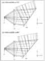
- FIG. (A) is a light ray diagram of Example 2
- FIG. (A) is a light ray diagram of Example 3
- (b) is a light ray diagram of Example 4.
- FIG. It is the schematic which shows the other structural example (modification 1) of a display optical system. It is the schematic which shows the other structural example (modification 2) of a display optical system.
- Visual inspection device 1-1 Display optical system and display element 1-2. Optical characteristics of display optical system 1-3. Observation optical system and imaging device 1-4. Control unit 2. 2. Visual inspection method 3. Effects of the embodiment Modifications etc.
- FIG. 1 is a schematic diagram of a visual inspection apparatus according to this embodiment.
- the visual inspection device 10 of the present embodiment is configured as a head-mounted visual inspection device that is attached to the head of a subject for visual field inspection.
- the visual inspection device 10 includes, for example, a head mount (HM) unit 100 and a control unit 400.
- HM head mount
- the HM unit 100 includes a housing (mounting body) 110 and a mounting tool 120 connected to the housing 110, and is configured to be mounted on the subject's head by the mounting tool 120.
- the housing 110 stores a display optical system (200) and an observation optical system (300), which will be described later.
- the display optical system (200) is provided in each of both eyes, and in the housing 110, a display element 240R corresponding to the right eye and a display element 240L corresponding to the left eye are provided.
- the wearing tool 120 includes a first belt that is bridged in a U-shape from both sides of the subject to the back of the head, and a second belt that is spanned to the top of the subject.
- the second belt may be configured to be adjustable in length.
- the control unit 400 is configured to control the display optical system (200), the observation optical system (300), and the like. Moreover, the control part 400 is arrange
- FIG. 2 is a schematic cross-sectional view of the visual inspection apparatus of the present embodiment.
- the visual inspection device 10 according to the present embodiment includes a display optical system 200 for presenting a visual target to the eyeball 20, and an observation optical system 300 for imaging the eyeball 20. ,have.
- the display optical system 200 is bent in order to reduce the size of the visual inspection device 10. Details will be described below.
- FIG. 2 shows an optical system (display optical system 200 and observation optical system 300) corresponding to one eye.
- the optical systems corresponding to the left and right eyes have the same configuration. have.
- the optical systems corresponding to the left and right eyes will be described without distinction, and the L and R symbols will be omitted.
- the pupil 21 is an exit pupil
- the light emitted from the retina 22 is imaged by the display element 240 and the light emitted from the display element 240 is imaged by the retina 22 have the same meaning in the optical system of the present embodiment.
- the case where light is actually emitted from the position of the display element 240 is referred to as “in the case of a forward light beam from the display element 240”, and the case where light is emitted from the position of the retina 22 is described as “from the retina 22”. Will be described as “in the case of a reverse ray”.
- the display optical system 200 is configured to guide light of a predetermined target to the retina 22 of the eyeball 20.
- the “target” here is a point or a figure that is presented to the eyeball of the subject during the visual field inspection.
- the display optical system 200 includes, for example, a first lens 210, a mirror 220, and a second lens group 230 in order from the eyeball 20 side.
- the first lens 210 functions as an objective lens when the eyeball 20 is used as an object, and is configured as a positive lens, for example.
- the optical axis 280a of the first lens 210 is disposed so as to pass through the center of the pupil 21 of the eyeball 20 (the center of the eyeball 20).
- the first lens 210 has a large positive refracting power (power) so that the light from the retina 22 is converged to a predetermined range in the case of a reverse ray from the retina 22.
- power positive refracting power
- the chief ray beam from the retina 22 passing through the end of the first lens 210 is bent by the first lens 210, and the chief ray beam from the retina 22 is reflected by the mirror 220.
- An image is formed (condensed) at a nearby position. All light from the retina 22 over a wide angle is converged by the first lens 210 within the range of the mirror 220. Details of the power of the first lens 210 will be described later.
- the mirror 220 is configured to reflect light of a specific wavelength and transmit other light. Specifically, the mirror 220 is configured as a cold mirror that reflects visible light and transmits infrared light, for example.
- the mirror 220 is provided on the side opposite to the eyeball 20 on the optical axis 280a of the first lens 210 with the first lens 210 interposed therebetween. Further, the mirror 220 is provided to be inclined at a predetermined angle with respect to the optical axis 280a of the first lens 210. In the case of a reverse ray from the retina 22, the light converged at a position near the mirror 220. Is reflected in a predetermined direction.
- the mirror 220 transmits infrared light reflected on the surface of the eyeball 20 described later to the side opposite to the eyeball 20 of the mirror 220.
- the second lens group 230 is a relay system that forms an image on the display element 240 again with the light imaged at the position near the mirror 220 from the retina 22 by the first lens 210 in the case of a reverse ray from the retina 22. It is configured to function, and is further configured to correct chromatic aberration and magnification.
- the second lens group 230 is provided on the optical axis 280b in the direction of reflecting through the mirror 220 with respect to the optical axis 280a of the first lens 210. That is, the optical axis 280 a from the pupil 21 of the eyeball 20 of the display optical system 200 to the mirror 220 and the optical axis 280 b from the mirror 220 of the display optical system 200 to the display element 240 are reflected from each other via the mirror 220. Is bent.
- the optical axis 280b from the mirror 220 of the display optical system 200 to the display element 240 is on a vertical plane including the optical axis 280a from the pupil 21 of the eyeball 20 of the display optical system 200 to the mirror 220.
- the optical axis 280 a from the pupil 21 of the eyeball 20 of the display optical system 200 to the mirror 220 is positioned vertically above.
- the optical axis 280b from the mirror 220 of the display optical system 200 to the display element 240 is inclined toward the head side from the direction perpendicular to the optical axis 280a from the pupil 21 of the eyeball 20 of the display optical system 200 to the mirror 220. ing. Thereby, the gravity center of the 2nd lens group 230 and the display element 240 comes close to the head side, and the weight balance as the visual inspection apparatus 10 whole can be improved.
- the second lens group 230 and the display element 240 may be too close to the head and interfere with the head.
- the second lens group 230 and the display element 240 can be prevented from interfering with the head.
- ⁇ ⁇ 90 ° when the subject tilts his / her head forward, the visual inspection device 10 may easily slip off the subject's head. In contrast, ⁇ ⁇ 90 ° suppresses the visual inspection device 10 from slipping off the subject's head even when the subject tilts the head forward. Can do.
- the second lens group 230 and the display element 240 can be prevented from interfering with the forehead.
- ⁇ ⁇ 80 ° the center of gravity of the second lens group 230 and the display element 240 is surely positioned on the head side, and the weight balance of the visual inspection apparatus 10 as a whole can be improved.
- the visual inspection device 10 can be reduced in size.
- the second lens group 230 includes at least a lens having a positive refractive power and a lens having a negative refractive power.
- the second lens group 230 includes, for example, in order from the eyeball 20 side, a positive lens 232, a negative lens 234, and a positive meniscus lens 236 convex to the eyeball 20 side.
- the outer diameter of the positive lens 232 is larger than the outer diameters of the negative lens 234 and the positive meniscus lens 236, and the outer diameter of the negative lens 234 is substantially equal to the outer diameter of the positive meniscus lens 236.
- the display element 240 is configured to present a predetermined visual target to the eyeball 20.
- the predetermined target is, for example, a fixed target such as a cross or a stimulus target having a predetermined brightness (luminance) for visual field inspection.
- the display element 240 is configured as, for example, a liquid crystal display element or an organic EL display element.
- the display element 240 is configured to be able to present a high-luminance target for visual field inspection, and the maximum luminance of the display element 240 is, for example, 3000 cd / m 2 or more.
- the display element 240 is provided on the side opposite to the mirror 220 across the second lens group 230 on the optical axis 280b of the second lens group 230. Further, the display surface of the display element 240 is arranged so that the normal direction thereof coincides with the optical axis 280 b of the second lens group 230. Further, the display element 240 is arranged so that light from the retina 22 is imaged through the first lens 210, the mirror 220, and the second lens group 230 in the case of a reverse ray from the retina 22. In other words, the display element 240 is disposed at a position optically conjugate with the retina 22 via the first lens 210, the mirror 220, and the second lens group 230.
- the display element 240 is connected to the control unit 400 and is configured to present a predetermined target to the eyeball 20 based on a signal from the control unit 400.
- the first lens 210 has a large positive refractive power as described above, and satisfies the following conditions.
- the focal length f1 of the first lens 210 is shorter than the optical distance D1 from the first lens 210 to the second lens group 230, that is, the following equation (4) Is satisfied. f1 ⁇ D1 (4)
- the focal length of the second lens group 230 is f2
- the focal length f1 of the first lens 210 and the focal length f2 of the second lens group 230 satisfy the following formula (5). 0 ⁇ f1 / f2 ⁇ 1.0 (5)
- the power of the first lens 210 is 20D (diopter) or more and 60D or less.
- the distance between the position of the pupil 21 and the first lens 210 changes.
- the power of the first lens 210 is less than 20D, the pupil and the first lens are separated from each other, and the declination of the light beam is also reduced. Therefore, in the case of a reverse ray from the retina, all of the light from the retina is mirrored. In order to make it reflect, a mirror may enlarge.
- a visual inspection device needs to install a mirror in front of each eye, if the subject's interpupillary distance (about 50 mm) is taken into account, if the mirror becomes too large, the mirror in each eye will be held. There is a possibility that members such as a lens barrel to interfere with each other.
- the power of the first lens 210 is 20D or more, in the case of a reverse ray from the retina 22, the light from the retina 22 over a wide angle is reflected by the first lens 210 within the range of the mirror 220.
- the image can be focused on the display element 240 having a predetermined size via the mirror 220 and the second lens group 230.
- the mirror can be reduced in size, and even when the distance between the pupils of the subject (about 50 mm) is taken into account, members such as a lens barrel that holds the mirrors in both eyes interfere with each other. This can be suppressed.
- the power of the first lens 210 exceeds 60D, the distance between the pupil and the first lens becomes too close, and the first lens may interfere with the eyelashes and eyelashes of the subject. In this case, the subject may be uncomfortable and an accurate visual field inspection may not be performed. Furthermore, the first lens is likely to be soiled and scratched, which may reduce the accuracy of the visual field inspection.
- the power of the first lens 210 is 60 D or less, it is possible to suppress the first lens 210 from interfering with the eyelashes and eyelashes of the subject. Further, it is possible to suppress the first lens from being stained or scratched, and it is possible to suppress a decrease in the accuracy of the visual field inspection.
- the first lens 210 is preferably as large as possible. However, since the distance between the human eyes is approximately 50 mm, the diameter of the first lens 210 is, for example, 50 mm or less so that the first lenses 210 of both eyes do not interfere with each other. .
- the maximum viewing angle of the display optical system 200 using the first lens 210 is preferably 30 degrees or more at a half angle of view. , 60 degrees or less (60 degrees or more and 120 degrees or less for all angles of view).
- the display element 240 on which the light from the retina 22 is imaged in the case of the reverse ray from the retina 22 can be reduced to a predetermined size. It can.
- the diagonal length (of the display surface) of the display element 240 is, for example, 1.5 inches or less, and preferably 1.0 inches or less.
- the visual inspection apparatus 10 can be reduced in size by reducing the display element 240.
- the first lens 210 and the second lens group 230 have the following optical characteristics.
- the Abbe number of the second lens group 230 having positive refractive power (for example, the positive lens 232 and the positive meniscus lens 236) is v2, the following expression (7) is satisfied. 45 ⁇ v2 ⁇ 80 (7)
- the Abbe number of a lens having a negative refractive power (for example, the negative lens 234) in the second lens group 230 is v3
- the following expression (8) is satisfied. 15 ⁇ v3 ⁇ 30
- each of the first lens 210 and the second lens group 230 has an aspherical surface.
- all the lenses constituting the display optical system 200 do not have to be aspherical lenses, and can be realized by, for example, a combination of a plurality of spherical lenses or a combination of a spherical lens and an aspherical lens.
- it is preferable that at least the lens closest to the eyeball position (in the example of the present embodiment, the first lens 210) among the plurality of lenses constituting the display optical system 200 is configured by an aspheric lens.
- the lens closest to the eyeball position is configured by an aspherical lens
- the number of lenses can be reduced by increasing the degree of freedom in optical design compared to the case where it is configured by a spherical lens. This is because the size and weight of 1 can be reduced.
- an increase in the optical path from the eyeball position to the mirror 220 corresponds to an increase in the length of the housing 110 in front of the subject, resulting in a problem that it is difficult to ensure a weight balance.
- the lens closest to the eyeball position is an aspherical lens and the forward projection amount is as small as possible.
- the observation optical system 300 is configured to guide an image of the eyeball 20 (such as an image of the iris and the pupil 21) to the image sensor 340.
- the observation optical system 300 includes, for example, in order from the eyeball 20 side, a light source 310, a first lens 210 shared with the display optical system 200, and a mirror 220 shared with the display optical system 200. And an imaging lens 320.
- a light source 310 that illuminates the eyeball 20 is provided between the eyeball 20 and the first lens 210 at a position outside the light beam passage range of the first lens 210.
- two light sources 310 are provided in the horizontal direction (or vertical direction) across the eyeball 20.
- the light source 310 is configured as an LED light source that irradiates infrared light, for example. By irradiating the eyeball 20 with infrared light, the eyeball 20 of the subject can be imaged without being detected by the retina 22 of the subject.
- the optical axis 280 a from the pupil 21 of the eyeball 20 of the display optical system 200 to the mirror 220 is changed to the observation optical system 300. This coincides with the optical axis (280a) from the pupil 21 of the eyeball 20 to the mirror. Further, as described above, the mirror 220 transmits infrared light that is irradiated from the light source 310 and reflected by the surface of the eyeball 20.
- the imaging lens 320 is configured as a relay lens that forms an image of infrared light transmitted through the mirror 220 on the imaging element 340.
- the optical axis 380a of the imaging lens 320 coincides with the optical axis 380a of the first lens 210 (positioned on the same axis).
- the imaging lens 320 is configured so that the image of the pupil 21 of the eyeball 20 is focused on the imaging element 340.
- the image sensor 340 is configured to image the eyeball 20 by detecting infrared light.
- the image sensor 340 is configured, for example, as a CCD (Charge Coupled Device) or a CMOS (Complementary Metal Oxide Semiconductor).
- the imaging element 340 is provided on the opposite side of the mirror 220 with the imaging lens 320 sandwiched on the optical axis 380 a of the imaging lens 320.
- the imaging surface of the imaging element 340 is arranged so that the normal direction thereof coincides with the optical axis 380 a of the imaging lens 320.
- the image sensor 340 is connected to the control unit 400 and configured to transmit an image obtained by capturing the eyeball 20 to the control unit 400.
- the control unit (computer unit) 400 is for performing operation control necessary for visual field inspection. Specifically, a CPU (Central Processing Unit), a RAM (Random Access Memory), a ROM (Read Only Memory), A combination of an HDD (Hard disk drive), various interfaces, and the like.
- the control unit 400 is configured to function as various means by the CPU executing a predetermined program stored in the ROM or HDD.
- the control unit 400 is connected to the display element 240 and the imaging element 340 so that they can communicate with each other by wire or wirelessly (A, B), and is configured to control the display element 240 and the imaging element 340.
- the visual inspection device 10 of the present embodiment is configured to perform a subjective visual field inspection described later, and the control unit 400 is configured to function as a sensitivity mapping unit.
- a switch 420 is provided in the vicinity of the subject so that the subject can answer whether the target is visible.
- the switch 420 is connected to the control unit 400 (C), and is configured to transmit a signal indicating that the subject has visually recognized the control unit 400.
- the sensitivity mapping means of the control unit 400 is a function for mapping the luminance of the display element 240 when the target is visible as the sensitivity of the retina 22 based on the signal transmitted from the switch 420.
- the visual inspection device 10 of the present embodiment is also configured to be able to perform an objective visual field inspection, which will be described later, and the control unit 400 includes a visual target presenting means, a miosis detection means, and a sensitivity mapping It is comprised so that it may function as a means.
- the optotype presenting means is a function for causing the display element 240 to present the optotype.
- the miosis detection means is based on the image of the pupil 21 acquired by the imaging device 340, and the miosis of the pupil 21 when the brightness of the target presented by the display element 240 is equal to or higher than a predetermined brightness (luminance). It is a function for detecting.
- the sensitivity mapping means is a function used not only in the subjective visual field examination but also in the objective visual examination, and the visual target that the display element 240 presented when the miosis detection means detects the miosis of the pupil 21. This is a function for mapping the brightness (luminance) of the image as the sensitivity of the retina 22.
- the predetermined program for realizing each of these functions is installed and used in the control unit 400, but may be provided by being stored in a storage medium readable by the control unit 400 prior to the installation. Alternatively, it may be provided to the control unit 400 through a communication line connected to the control unit 400.
- the control unit 400 in which the predetermined program is installed may not necessarily be mounted on the visual inspection device 10 as long as it can give an operation control instruction to each unit of the visual inspection device 10. It may be connected to the inspection apparatus 10 via a communication line.
- the visual inspection apparatus 10 according to the present embodiment can perform dynamic quantitative visual field inspection, static quantitative visual field inspection, fundus visual field inspection (microperimetry), electroretinography (ERG), and other inspections.
- a static quantitative visual field inspection there are a subjective visual field inspection and an objective visual field inspection, and the visual inspection apparatus 10 according to the present embodiment can perform any type of inspection.
- the subjective visual field inspection is performed as follows. First, the HM unit 100 of the visual inspection apparatus 10 is attached to the subject's head, and the subject is provided with the switch 420.
- the optotype presenting means of the control unit 400 causes the display element 240 to present the optotype at one point in the field of view, and gradually increases the brightness of the optotype. When the brightness of the target becomes equal to or higher than the predetermined brightness, the subject can see the target. At this time, the subject presses the switch 420. Then, a signal indicating that the subject has visually recognized is transmitted from the switch 420 to the control unit 400.
- the sensitivity mapping means of the control unit 400 presents the target with a value corresponding to the brightness of the target when the target becomes visible based on the signal transmitted from the switch 420. Retinal sensitivity in By performing the same measurement for each point in the field of view, the sensitivity mapping means of the control unit 400 creates a map of the sensitivity of the retina 22 in the field of view.
- the objective visual field inspection is performed as follows. First, the HM unit 100 of the visual inspection device 10 is attached to the subject's head. In this case, the subject need not have the switch 420.
- the optotype presenting means of the control unit 400 causes the display element 240 to present the optotype at one point in the field of view, and gradually increases the brightness of the optotype.
- the light source 310 irradiates the subject's eyeball 20 with infrared light, and the imaging element 340 images the pupil 21 of the subject's eyeball 20.
- the subject can see the visual target when the retina 22 of the subject senses the light of the visual target.
- the pupil of the subject changes (miosis) according to the brightness of the visual target.
- the miosis detection means of the control unit 400 performs image analysis based on the image of the pupil 21 acquired by the image sensor 340, so that the brightness of the target presented by the display element 240 becomes equal to or higher than a predetermined brightness. The miosis of the pupil 21 is detected.
- the sensitivity mapping means of the control unit 400 presents the display element 240 when the miosis detection means detects the miosis of the pupil 21.
- the brightness of the target that has been set as the sensitivity of the retina 22. By performing the same measurement for each point in the field of view, the sensitivity mapping means of the control unit 400 automatically creates a map of the sensitivity of the retina 22 in the field of view.
- the objective visual field test may use a single upper threshold stimulation method in which a bright target is displayed at one point on the display surface of the display element 240 and a sensitivity map is created by observing the degree of reduction of the pupil diameter. good.
- the optical axis 280a from the pupil 21 of the eyeball 20 of the display optical system 200 to the mirror 220 and the optical axis 280b from the mirror 220 of the display optical system 200 to the display element 240 are mirrored. It is bent in the direction of reflecting each other through 220. Thereby, the magnitude
- a head-mounted visual inspection apparatus in order to present a visual target over a wide angle with respect to the eyeball without increasing the size of the display element that presents the visual target, a combination of a plurality of lenses is used. It is necessary to enlarge the display optical system that guides the target light to the retina of the eyeball.
- the display element is disposed so as to face the eyeball of the subject and the display optical system is provided linearly, only the display optical system is projected in front of the subject's head. As the display optical system increases, the amount of protrusion of the housing forward of the head also increases.
- the display optical system 200 is bent via the mirror 220. Thereby, even if the display optical system 200 becomes large, it can be avoided that only the display optical system 200 protrudes in front of the subject's head, and the amount of protrusion of the housing forward of the head can be reduced. Can be suppressed. Therefore, the size of the visual inspection apparatus 10 as a whole can be reduced. Further, the visual inspection device 10 can be stabilized when the visual inspection device 10 is mounted.
- the optical axis 280b from the mirror 220 of the display optical system 200 to the display element 240 is in the direction perpendicular to the optical axis 280a from the pupil 21 of the eyeball 20 of the display optical system 200 to the mirror 220. It is inclined to the head side. Thereby, the weight balance as the visual inspection apparatus 10 whole can be improved.
- a problem when the display element is arranged so as to face the eyeball of the subject and the display optical system is provided linearly will be described.
- the display optical system protrudes in front of the subject's head.
- the center of gravity of the display optical system is biased forward of the subject's head, and the weight balance of the visual inspection apparatus cannot be maintained.
- the subject's head may move, so if the weight balance of the visual inspection device is poor, the visual inspection device may fall off or tilt from the subject's head. there's a possibility that.
- the optical axis 280b on the bent side of the display optical system 200 is inclined toward the head side.
- the center of gravity of the bent side of the display optical system 200 can be brought closer to the head side, and the center of gravity of the display optical system 200 is in front of the head of the subject. Can be suppressed. Therefore, the weight balance of the visual inspection apparatus 10 as a whole can be improved. Even when the subject's head is moved, the visual inspection device 10 is displaced or tilted from the head by bringing the center of gravity of the bent side of the display optical system 200 closer to the head. Can be suppressed.
- the first lens 210 has a large positive refractive power. Specifically, the focal length f1 of the first lens 210 satisfies the above formulas (2) and (3). Furthermore, the power of the first lens 210 is 20D (diopter) or more and 60D or less. Thereby, in the case of a reverse ray from the retina 22, all the light from the retina 22 over a wide angle can be converged within the range of the mirror 220 by the first lens 210.
- the light from the retina may not be sufficiently converged at the position of the mirror of the first lens and may diverge at the position of the mirror. There is sex. In this state, a part of the light from the retina is not reflected by the mirror and is not imaged at the position of the display element. In this case, in order to reflect all of the light from the retina by the mirror, the mirror must be enlarged, which may increase the size of the visual inspection apparatus.
- the principal ray beam from the retina 22 passing through the end of the first lens 210 is It can be bent by the first lens 210 and imaged (condensed) at a position near the mirror 220, for example. All light from the retina 22 over a wide angle can be converged within the range of the mirror 220 by the first lens 210. Then, the light converged by the first lens 210 can be reflected by the mirror 220 and imaged at the position of the display element 240 by the second lens group 230.
- the target from the display element 240 having a predetermined size is applied to the eyeball 20 by the first lens 210.
- it can be presented over a wide angle (angle of view).
- the enlargement of the mirror 220 itself can be suppressed, and the visual inspection device 10 can be downsized. Is possible.
- control unit 400 is provided on the occipital side of the wearing tool 120 , but the control unit may be stored in the housing of the HM unit. Further, the control unit may be provided separately from the HM unit.
- the first lens 210 of the display optical system 200 is configured with one lens
- the first lens may be a lens group configured with a plurality of lenses.
- the mirror 220 is a cold mirror
- the mirror may be a hot mirror or a dichroic mirror.
- the optical axis 280b from the mirror 220 of the display optical system 200 to the display element 240 is positioned vertically above the optical axis from the pupil 21 of the eyeball 20 of the display optical system 200 to the mirror 220.
- the optical axis from the mirror of the display optical system to the display element may be positioned vertically lower than the optical axis from the pupil of the eyeball of the display optical system to the mirror.
- the display optical system 200 is configured with a total of four lenses
- the observation optical system 300 is configured with a total of two lenses (one of which is shared with the display optical system 200).
- the number and shape of lenses constituting the system, the lens interval in the optical axis direction, and the like can be changed as necessary.
- the second lens group 230 is preferably composed of a plurality of lenses in order to correct chromatic aberration and image magnification by combining a lens having a positive power and a lens having a negative power.
- the mirror 220 may be constituted by a dichroic mirror.
- FIG. 5 is a schematic diagram showing another configuration example (modification example 1) of the display optical system.
- FIG. 6 is a schematic diagram illustrating another configuration example (modification example 2) of the display optical system.
- the positive meniscus lens 236 belonging to the second lens group 230 of the display optical system 200 can be moved in the optical axis direction by a lens moving mechanism (not shown). It is different from the form.
- a lens moving mechanism not shown
- the second lens group 230 of the display optical system 200 is configured by using a total of four lenses 232 to 236 by adding a positive lens 235, and a planar type.
- size of the display surface of the display element 240 is different from the said embodiment.
- the visual target can be displayed more clearly to the subject.
- FIGS. 3A is a ray diagram of the first embodiment
- FIG. 3B is a ray diagram of the second embodiment
- FIG. 4A is a ray diagram of the third embodiment.
- (B) is a ray diagram of Example 4.
- FIGS. 3 (a) to 4 (b) show the results of simulation by back ray tracing using the pupil 21 as the exit pupil, respectively.
- the second lens group 230 is omitted.
- the ratios of the size and interval of the first lens and the mirror are set to be equal to the actual ratio.
- the vertical direction is the y direction
- the direction perpendicular to the y direction and perpendicular to the optical axis of the first lens 210 is the x direction
- the direction perpendicular to the y direction and parallel to the optical axis of the first lens 210 is the z direction.
- the total angle of view of light rays from the pupil 21 toward the first lens 210 was 70 °.
- Examples 1 and 2 In Example 1 in FIG. 3A and Example 2 in FIG. 3B, the principal ray emitted from the pupil 21 is condensed near the mirror 220, and all of the entire field angle over 70 ° is collected. It was confirmed that the main light beam converged within the range of the mirror 220.
- the required diameter of the mirror 220 in the x direction was about 54 mm. Since the required diameter in the x direction of the mirror 220 approaches the interpupillary distance (about 50 mm), the required diameter in the x direction of the mirror 220 is a limit that members such as a lens barrel holding the mirror 220 in both eyes do not interfere with each other. It was the size of. Therefore, it was confirmed that the lower limit value of the power of the first lens 210 was 20D.
- Examples 3 and 4 Also in Example 3 of FIG. 4A and Example 4 of FIG. 4B, the principal ray emitted from the pupil 21 is condensed near the mirror 220 and all over the entire angle of view of 70 °. It was confirmed that the light beam of the principal ray converged within the range of the mirror 220.
- Example 3 in FIG. 4A and Example 4 in FIG. 4B the power of the first lens 210 is increased, so that Example 1 in FIG. It was confirmed that the optical system was smaller than the optical system of Example 2 in (b).
- Example 3 in FIG. 4A and Example 4 in FIG. 4B the distance between the pupil 21 and the first lens 210 is reduced due to the increase in the power of the first lens 210.
- the distance between the pupil 21 and the first lens 210 is a limit distance at which the first lens 210 does not interfere with the eyelashes or wrinkles of the subject. Therefore, it was confirmed that the upper limit value of the power of the first lens 210 was 60D.
Landscapes
- Life Sciences & Earth Sciences (AREA)
- Health & Medical Sciences (AREA)
- Medical Informatics (AREA)
- Biophysics (AREA)
- Ophthalmology & Optometry (AREA)
- Engineering & Computer Science (AREA)
- Biomedical Technology (AREA)
- Heart & Thoracic Surgery (AREA)
- Physics & Mathematics (AREA)
- Molecular Biology (AREA)
- Surgery (AREA)
- Animal Behavior & Ethology (AREA)
- General Health & Medical Sciences (AREA)
- Public Health (AREA)
- Veterinary Medicine (AREA)
- Eye Examination Apparatus (AREA)
Abstract
Provided is a compact, head-mounted type visual examination apparatus. The visual examination apparatus is a head-mounted type visual examination apparatus that is attached to the head of a person being examined, the visual examination apparatus comprising a display element that presents visual targets to an eyeballof the person being examined, a display optical system that guides the light of the visual target presented by the display element to the retina of the eyeball, an image acquisition element that acquires an image of the eyeball, and an observation optical system that guides the image of the eyeball to the image acquisition element, wherein the display optical system comprises a mirror closer to the eyeball than the display element, the mirror reflecting a portion of the light and transmitting the remainder of the light, wherein an optical axis from the pupil of the eyeball to the mirror in the display optical system and an optical axis from the pupil of the eyeball to the mirror in the observation optical system are in alignment, and wherein the optical axis from the pupil of the eyeball to the mirror in the display optical system and the optical axis from the mirror to the display element in the display optical system are bent by the mirror.
Description
本発明は、視覚検査装置に関する。
The present invention relates to a visual inspection apparatus.
緑内障などの視野狭窄の症状を診断する視野検査を行う視覚検査装置として、ハンフリー視野計が知られている。ハンフリー視野計には、ドーム型のスクリーンが設けられている。視野検査では、被検者は、スクリーンの前方に設けられた受け台に頭部を固定する。そして、スクリーンに視標を呈示したときに、視標が見えたかを被検者自身が回答することにより、被検者の視野を計測する。
Humphrey perimeter is known as a visual inspection device that performs visual field inspection to diagnose symptoms of visual field constriction such as glaucoma. The Humphrey perimeter is provided with a dome-shaped screen. In the visual field inspection, the subject fixes his head to a cradle provided in front of the screen. Then, when the target is presented on the screen, the subject himself / herself answers whether the target is visible, thereby measuring the visual field of the subject.
被検者の視野全体を計測するためには、眼球に対して広い角度(視野角)に亘って視標を呈示する必要がある。ハンフリー視野計では、被験者の眼球とドーム型のスクリーンとの間にレンズ等の光学系が設けられていないことから、眼球に対して広い角度に亘って視標を呈示するために、広いスクリーンが必要とされていた。その結果、ハンフリー視野計の装置全体が大型化しており、さらには、ハンフリー視野計を設置するための広い設置場所や、ハンフリー視野計および被検者を暗空間に収容する暗室などが必要とされていた。
In order to measure the entire visual field of the subject, it is necessary to present a visual target over a wide angle (viewing angle) with respect to the eyeball. In the Humphrey perimeter, since an optical system such as a lens is not provided between the eyeball of the subject and the dome-shaped screen, a wide screen is used to present a visual target over a wide angle with respect to the eyeball. Was needed. As a result, the entire Humphrey perimeter device has become larger, and further, a large installation place for installing the Humphrey perimeter and a darkroom for housing the Humphrey perimeter and the subject in a dark space are required. It was.
そこで、ハンフリー視野計が大型化するという問題を解決するため、被検者の頭部に装着されるヘッドマウント型の視覚検査装置が提案されている(例えば、特許文献1)。特許文献1の視覚検査装置には、被検者の眼球に対して視標を呈示する表示素子と、表示素子に呈示される視標の光を眼球に導くレンズと、ハーフミラーと、表示素子の位置をアライメントするために眼球を撮像する撮像素子と、を有する測定部が設けられている。測定部は、被検者の頭部に装着されるゴーグル型の枠に設置されている。
Therefore, in order to solve the problem that the Humphrey perimeter is increased in size, a head-mounted visual inspection device that is worn on the subject's head has been proposed (for example, Patent Document 1). The visual inspection device of Patent Document 1 includes a display element that presents a visual target to the eyeball of a subject, a lens that guides light of the visual target presented to the display element to the eyeball, a half mirror, and a display element In order to align the positions, an image sensor that images the eyeball is provided. The measurement unit is installed in a goggle-type frame that is attached to the head of the subject.
しかしながら、特許文献1の構成では、以下の理由により、大型の表示素子が必要となるため、ヘッドマウント型の視覚検査装置が大型化する可能性があった。
However, in the configuration of Patent Document 1, a large display element is required for the following reasons, and thus there is a possibility that the head-mounted visual inspection apparatus is enlarged.
特許文献1の技術背景として、映像を表示することだけを目的とした通常のヘッドマウントディスプレイでは、表示素子を被検者の眼球に対向するように配置することが主流となっていたことから、特許文献1のヘッドマウント型の視覚検査装置においても、表示素子を被検者の眼球に対向するように配置し、一方で、ハーフミラーを介して撮像素子側の光軸を屈曲させて配置していた。また、1枚のレンズのみを用いて、表示素子の画像を被検者の網膜に結像していた。このような構成を有する特許文献1のヘッドマウント型の視覚検査装置では、眼球に対して広い角度に亘って視標を呈示するために、大型の表示素子が必要とされていた。その結果、表示素子を収容する測定部が大型化し、視覚検査装置全体が大型化する可能性があった。
As a technical background of Patent Document 1, in a normal head-mounted display only for displaying an image, it has been mainstream to arrange the display element so as to face the eyeball of the subject. Also in the head-mounted visual inspection apparatus of Patent Document 1, the display element is arranged so as to face the eyeball of the subject, and on the other hand, the optical axis on the imaging element side is bent through a half mirror. It was. Further, the image of the display element is formed on the retina of the subject using only one lens. In the head-mounted visual inspection apparatus of Patent Document 1 having such a configuration, a large display element is required in order to present a visual target over a wide angle with respect to the eyeball. As a result, there is a possibility that the measuring unit that accommodates the display element is enlarged and the entire visual inspection apparatus is enlarged.
そこで、本発明は、小型化したヘッドマウント型の視覚検査装置を提供することを、主たる目的とする。
Therefore, the main object of the present invention is to provide a miniaturized head-mounted visual inspection apparatus.
本発明の第1の態様は、
被検者の頭部に装着されるヘッドマウント型の視覚検査装置であって、
前記被検者の眼球に対して視標を呈示する表示素子と、
前記表示素子に呈示される前記視標の光を前記眼球の網膜に導く表示光学系と、
前記眼球を撮像する撮像素子と、
前記眼球の像を前記撮像素子に導く観察光学系と、
を有し、
前記表示光学系は、前記表示素子よりも前記眼球側に、特定の波長の光を反射し、その他の光を透過するミラーを有し、
前記表示光学系の前記眼球の瞳孔から前記ミラーまでの光軸と、前記観察光学系の前記眼球の瞳孔から前記ミラーまでの光軸とが一致しており、
前記表示光学系の前記眼球の瞳孔から前記ミラーまでの光軸と、前記表示光学系の前記ミラーから前記表示素子までの光軸とは、前記ミラーを介して屈曲されている視覚検査装置である。
本発明の第2の態様は、
前記表示光学系の前記ミラーから前記表示素子までの光軸は、前記表示光学系の前記眼球の瞳孔から前記ミラーまでの光軸に垂直な方向よりも頭部側に傾斜している第1の態様に記載の視野検査装置である。
本発明の第3の態様は、
前記表示光学系の前記眼球の瞳孔から前記ミラーまでの光軸と、前記表示光学系の前記ミラーから前記表示素子までの光軸とのなす角度をαとしたとき、以下の式(1)を満たす第1又は第2の態様に記載の視覚検査装置である。
40°<α<90° ・・・(1)
本発明の第4の態様は、
前記表示光学系は、
前記眼球と前記ミラーとの間に設けられ、光軸が前記眼球の瞳孔の中心を通過するよう設けられる第1レンズと、
前記ミラーと前記表示素子との間に設けられ、前記第1レンズの光軸に対して前記ミラーを介して反射する方向の光軸上に設けられる第2レンズ群と、
を有し、
前記観察光学系は、前記第1レンズを前記表示光学系と共有している第1~第3の態様のいずれかに記載の視覚検査装置である。
本発明の第5の態様は、
前記第1レンズの焦点距離は、前記第1レンズから前記第2レンズ群までの光学的距離よりも短い第4の態様に記載の視覚検査装置である。
本発明の第6の態様は、
前記第1レンズのパワーは、20D以上60D以下である第4又は第5の態様に記載の視覚検査装置である。
本発明の第7の態様は、
前記表示素子の対角長は、1.5インチ以下である第1~第6の態様のいずれかに記載の視覚検査装置である。 The first aspect of the present invention is:
A head-mounted visual inspection device mounted on a subject's head,
A display element for presenting a visual target to the eyeball of the subject;
A display optical system for guiding the light of the optotype presented on the display element to the retina of the eyeball;
An image sensor for imaging the eyeball;
An observation optical system for guiding the image of the eyeball to the image sensor;
Have
The display optical system has a mirror that reflects light of a specific wavelength and transmits other light on the eyeball side of the display element,
The optical axis from the pupil of the eyeball of the display optical system to the mirror coincides with the optical axis from the pupil of the eyeball of the observation optical system to the mirror,
The optical axis from the pupil of the eyeball of the display optical system to the mirror, and the optical axis from the mirror to the display element of the display optical system are visual inspection devices bent through the mirror. .
The second aspect of the present invention is:
The optical axis from the mirror of the display optical system to the display element is inclined to the head side from the direction perpendicular to the optical axis from the pupil of the eyeball to the mirror of the display optical system. It is a visual field inspection apparatus as described in an aspect.
The third aspect of the present invention is:
When the angle formed by the optical axis from the pupil of the eyeball of the display optical system to the mirror and the optical axis from the mirror of the display optical system to the display element is α, the following equation (1) is obtained: It is a visual inspection apparatus given in the 1st or 2nd mode to satisfy.
40 ° <α <90 ° (1)
The fourth aspect of the present invention is:
The display optical system includes:
A first lens provided between the eyeball and the mirror, the optical axis passing through the center of the pupil of the eyeball;
A second lens group provided between the mirror and the display element and provided on an optical axis in a direction of reflecting through the mirror with respect to the optical axis of the first lens;
Have
The visual inspection apparatus according to any one of the first to third aspects, wherein the observation optical system shares the first lens with the display optical system.
According to a fifth aspect of the present invention,
The focal length of the first lens is the visual inspection device according to the fourth aspect, which is shorter than the optical distance from the first lens to the second lens group.
The sixth aspect of the present invention is:
The power of the first lens is the visual inspection device according to the fourth or fifth aspect, which is 20D or more and 60D or less.
The seventh aspect of the present invention is
The visual inspection apparatus according to any one of the first to sixth aspects, wherein a diagonal length of the display element is 1.5 inches or less.
本発明によれば、小型化したヘッドマウント型の視覚検査装置を提供することができる。
According to the present invention, a miniaturized head mounted visual inspection apparatus can be provided.
以下、本発明の実施の形態について図面を参照しつつ詳細に説明する。
本実施形態においては、次の順序で説明を行う。
1.視覚検査装置
1-1.表示光学系および表示素子
1-2.表示光学系の光学特性等
1-3.観察光学系および撮像素子
1-4.制御部
2.視覚検査方法
3.実施の形態による効果
4.変形例等 Hereinafter, embodiments of the present invention will be described in detail with reference to the drawings.
In the present embodiment, description will be given in the following order.
1. Visual inspection device 1-1. Display optical system and display element 1-2. Optical characteristics of display optical system 1-3. Observation optical system and imaging device 1-4. Control unit 2. 2. Visual inspection method 3. Effects of the embodiment Modifications etc.
<1.視覚検査装置>
図1は、本実施形態の視覚検査装置の概略図である。図1に示されているように、本実施形態の視覚検査装置10は、視野検査の被検者の頭部に装着されるヘッドマウント型の視覚検査装置として構成されている。具体的には、視覚検査装置10は、例えば、ヘッドマウント(HM)部100と、制御部400とを備えている。 <1. Visual inspection device>
FIG. 1 is a schematic diagram of a visual inspection apparatus according to this embodiment. As shown in FIG. 1, thevisual inspection device 10 of the present embodiment is configured as a head-mounted visual inspection device that is attached to the head of a subject for visual field inspection. Specifically, the visual inspection device 10 includes, for example, a head mount (HM) unit 100 and a control unit 400.
図1は、本実施形態の視覚検査装置の概略図である。図1に示されているように、本実施形態の視覚検査装置10は、視野検査の被検者の頭部に装着されるヘッドマウント型の視覚検査装置として構成されている。具体的には、視覚検査装置10は、例えば、ヘッドマウント(HM)部100と、制御部400とを備えている。 <1. Visual inspection device>
FIG. 1 is a schematic diagram of a visual inspection apparatus according to this embodiment. As shown in FIG. 1, the
HM部100は、筺体(装着本体)110と、筺体110に接続された装着具120と、を有しており、装着具120によって被検者の頭部に装着可能に構成されている。筺体110内には、後述する表示光学系(200)および観察光学系(300)等が格納されている。例えば、両目のそれぞれに表示光学系(200)が設けられており、筺体110内には、右眼に対応した表示素子240Rと、左眼に対応した表示素子240Lとが設けられている。また、装着具120は、被検者の両側頭部から後頭部にかけてU字状に架け渡される第1ベルトと、被検者の頭頂部に架け渡される第2ベルトと、を備えている。第2ベルトは、長さを調整可能に構成されていてもよい。
The HM unit 100 includes a housing (mounting body) 110 and a mounting tool 120 connected to the housing 110, and is configured to be mounted on the subject's head by the mounting tool 120. The housing 110 stores a display optical system (200) and an observation optical system (300), which will be described later. For example, the display optical system (200) is provided in each of both eyes, and in the housing 110, a display element 240R corresponding to the right eye and a display element 240L corresponding to the left eye are provided. In addition, the wearing tool 120 includes a first belt that is bridged in a U-shape from both sides of the subject to the back of the head, and a second belt that is spanned to the top of the subject. The second belt may be configured to be adjustable in length.
制御部400は、表示光学系(200)および観察光学系(300)等を制御するよう構成されている。また、制御部400は、例えば、装着具120の後頭部側に配置されている。これにより、筺体110と制御部400との前後の重量バランスを保つことができる。制御部400については詳細を後述する。
The control unit 400 is configured to control the display optical system (200), the observation optical system (300), and the like. Moreover, the control part 400 is arrange | positioned at the back head side of the mounting tool 120, for example. Thereby, the weight balance before and behind the housing 110 and the control part 400 can be maintained. Details of the control unit 400 will be described later.
図2は、本実施形態の視覚検査装置の断面概略図である。図2に示されているように、本実施形態の視覚検査装置10は、眼球20に対して視標を呈示するための表示光学系200と、眼球20を撮像するための観察光学系300と、を有している。本実施形態では、視覚検査装置10を小型化するために、表示光学系200が屈曲されている。以下、詳細を説明する。
FIG. 2 is a schematic cross-sectional view of the visual inspection apparatus of the present embodiment. As shown in FIG. 2, the visual inspection device 10 according to the present embodiment includes a display optical system 200 for presenting a visual target to the eyeball 20, and an observation optical system 300 for imaging the eyeball 20. ,have. In the present embodiment, the display optical system 200 is bent in order to reduce the size of the visual inspection device 10. Details will be described below.
なお、図2には、片眼に対応する光学系(表示光学系200および観察光学系300)が示されているが、例えば、左右の眼のそれぞれに対応する光学系は、互いに同様の構成を有している。以下の説明では、左右の眼のそれぞれに対応する光学系を区別なく記載し、LおよびRの符号を省略する。
FIG. 2 shows an optical system (display optical system 200 and observation optical system 300) corresponding to one eye. For example, the optical systems corresponding to the left and right eyes have the same configuration. have. In the following description, the optical systems corresponding to the left and right eyes will be described without distinction, and the L and R symbols will be omitted.
また、以下において、光が網膜22の位置から瞳孔21を介して出射される(瞳孔21を射出瞳とする)と仮定して説明する場合がある。網膜22から出射された光が表示素子240で結像されることと、表示素子240から出射された光が網膜22で結像されることとは、本実施形態の光学系では同じ意味をなす。以下においては、実際に光が表示素子240の位置から出射される場合を「表示素子240からの順方向光線の場合」とし、仮に光が網膜22の位置から出射される場合を「網膜22からの逆方向光線の場合」として説明する。
In the following description, it is assumed that light is emitted from the position of the retina 22 through the pupil 21 (the pupil 21 is an exit pupil). The light emitted from the retina 22 is imaged by the display element 240 and the light emitted from the display element 240 is imaged by the retina 22 have the same meaning in the optical system of the present embodiment. . In the following, the case where light is actually emitted from the position of the display element 240 is referred to as “in the case of a forward light beam from the display element 240”, and the case where light is emitted from the position of the retina 22 is described as “from the retina 22”. Will be described as “in the case of a reverse ray”.
(1-1.表示光学系および表示素子)
表示光学系200は、所定の視標の光を眼球20の網膜22に導くよう構成されている。ここでいう「視標」とは、視野検査の際に被検者の眼球に対して呈示される点または図形のことである。表示光学系200は、例えば、眼球20側から順に、第1レンズ210と、ミラー220と、第2レンズ群230と、を有している。 (1-1. Display optical system and display element)
The displayoptical system 200 is configured to guide light of a predetermined target to the retina 22 of the eyeball 20. The “target” here is a point or a figure that is presented to the eyeball of the subject during the visual field inspection. The display optical system 200 includes, for example, a first lens 210, a mirror 220, and a second lens group 230 in order from the eyeball 20 side.
表示光学系200は、所定の視標の光を眼球20の網膜22に導くよう構成されている。ここでいう「視標」とは、視野検査の際に被検者の眼球に対して呈示される点または図形のことである。表示光学系200は、例えば、眼球20側から順に、第1レンズ210と、ミラー220と、第2レンズ群230と、を有している。 (1-1. Display optical system and display element)
The display
第1レンズ210は、眼球20を物体としたときに対物レンズとして機能し、例えば正レンズとして構成されている。第1レンズ210の光軸280aは、眼球20の瞳孔21の中心(眼球20の中心)を通過するように配置されている。
The first lens 210 functions as an objective lens when the eyeball 20 is used as an object, and is configured as a positive lens, for example. The optical axis 280a of the first lens 210 is disposed so as to pass through the center of the pupil 21 of the eyeball 20 (the center of the eyeball 20).
第1レンズ210は、網膜22からの逆方向光線の場合に網膜22からの光を所定の範囲に収束させるように、大きな正の屈折力(パワー)を有している。網膜22からの逆方向光線の場合に、第1レンズ210の端部を通る網膜22からの主光線の光束は、第1レンズ210によって屈曲され、網膜22からの主光線の光束は、ミラー220付近の位置に結像(集光)される。広い角度に亘った網膜22からの全ての光は、第1レンズ210によってミラー220の範囲内に収束される。この第1レンズ210のパワーについては、詳細を後述する。
The first lens 210 has a large positive refracting power (power) so that the light from the retina 22 is converged to a predetermined range in the case of a reverse ray from the retina 22. In the case of a reverse ray from the retina 22, the chief ray beam from the retina 22 passing through the end of the first lens 210 is bent by the first lens 210, and the chief ray beam from the retina 22 is reflected by the mirror 220. An image is formed (condensed) at a nearby position. All light from the retina 22 over a wide angle is converged by the first lens 210 within the range of the mirror 220. Details of the power of the first lens 210 will be described later.
ミラー220は、特定の波長の光を反射し、その他の光を透過するよう構成されている。具体的には、ミラー220は、例えば、可視光を反射し赤外光を透過するコールドミラーとして構成されている。ミラー220は、第1レンズ210の光軸280a上で第1レンズ210を挟んで眼球20と反対側に設けられている。また、ミラー220は、第1レンズ210の光軸280aに対して所定の角度で傾斜して設けられており、網膜22からの逆方向光線の場合に、ミラー220付近の位置で収束された光を所定の方向に反射するようになっている。一方で、ミラー220は、後述する眼球20表面で反射した赤外光をミラー220の眼球20と反対側に透過するようになっている。
The mirror 220 is configured to reflect light of a specific wavelength and transmit other light. Specifically, the mirror 220 is configured as a cold mirror that reflects visible light and transmits infrared light, for example. The mirror 220 is provided on the side opposite to the eyeball 20 on the optical axis 280a of the first lens 210 with the first lens 210 interposed therebetween. Further, the mirror 220 is provided to be inclined at a predetermined angle with respect to the optical axis 280a of the first lens 210. In the case of a reverse ray from the retina 22, the light converged at a position near the mirror 220. Is reflected in a predetermined direction. On the other hand, the mirror 220 transmits infrared light reflected on the surface of the eyeball 20 described later to the side opposite to the eyeball 20 of the mirror 220.
第2レンズ群230は、網膜22からの逆方向光線の場合に、第1レンズ210によって網膜22からミラー220付近の位置に結像された光を、再び表示素子240に結像するリレー系として機能するように構成されており、さらに、色収差や倍率を補正するように構成されている。
The second lens group 230 is a relay system that forms an image on the display element 240 again with the light imaged at the position near the mirror 220 from the retina 22 by the first lens 210 in the case of a reverse ray from the retina 22. It is configured to function, and is further configured to correct chromatic aberration and magnification.
第2レンズ群230は、第1レンズ210の光軸280aに対してミラー220を介して反射する方向の光軸280b上に設けられている。つまり、表示光学系200の眼球20の瞳孔21からミラー220までの光軸280aと、表示光学系200のミラー220から表示素子240までの光軸280bとは、ミラー220を介して互いに反射する方向に屈曲されている。本実施形態では、例えば、表示光学系200のミラー220から表示素子240までの光軸280bは、表示光学系200の眼球20の瞳孔21からミラー220までの光軸280aを含む鉛直平面上において、表示光学系200の眼球20の瞳孔21からミラー220までの光軸280aよりも鉛直上側に位置している。また、表示光学系200のミラー220から表示素子240までの光軸280bは、表示光学系200の眼球20の瞳孔21からミラー220までの光軸280aに垂直な方向よりも頭部側に傾斜している。これにより、第2レンズ群230および表示素子240の重心が頭部側に接近するようになり、視覚検査装置10全体としての重量バランスを良くすることができる。
The second lens group 230 is provided on the optical axis 280b in the direction of reflecting through the mirror 220 with respect to the optical axis 280a of the first lens 210. That is, the optical axis 280 a from the pupil 21 of the eyeball 20 of the display optical system 200 to the mirror 220 and the optical axis 280 b from the mirror 220 of the display optical system 200 to the display element 240 are reflected from each other via the mirror 220. Is bent. In the present embodiment, for example, the optical axis 280b from the mirror 220 of the display optical system 200 to the display element 240 is on a vertical plane including the optical axis 280a from the pupil 21 of the eyeball 20 of the display optical system 200 to the mirror 220. The optical axis 280 a from the pupil 21 of the eyeball 20 of the display optical system 200 to the mirror 220 is positioned vertically above. In addition, the optical axis 280b from the mirror 220 of the display optical system 200 to the display element 240 is inclined toward the head side from the direction perpendicular to the optical axis 280a from the pupil 21 of the eyeball 20 of the display optical system 200 to the mirror 220. ing. Thereby, the gravity center of the 2nd lens group 230 and the display element 240 comes close to the head side, and the weight balance as the visual inspection apparatus 10 whole can be improved.
ここで、表示光学系200の眼球20の瞳孔21からミラー220までの光軸280aと、表示光学系200のミラー220から表示素子240までの光軸280bとのなす角度をαとしたとき、以下の式(1)を満たす。
40°<α<90° ・・・(1) Here, when the angle between theoptical axis 280a from the pupil 21 of the eyeball 20 of the display optical system 200 to the mirror 220 and the optical axis 280b from the mirror 220 of the display optical system 200 to the display element 240 is α, (1) is satisfied.
40 ° <α <90 ° (1)
40°<α<90° ・・・(1) Here, when the angle between the
40 ° <α <90 ° (1)
α≦40°である場合、第2レンズ群230および表示素子240が頭部に接近しすぎて、頭部と干渉してしまう可能性がある。これに対して、α>40°であることにより、第2レンズ群230および表示素子240が頭部と干渉することを抑制することができる。一方、α≧90°である場合、被検者が頭部を前方に傾けた際に、視覚検査装置10が被検者の頭部から容易にずれ落ちてしまう可能性がある。これに対して、α<90°であることにより、被検者が頭部を前方に傾けた場合であっても、視覚検査装置10が被検者の頭部からずれ落ちることを抑制することができる。
When α ≦ 40 °, the second lens group 230 and the display element 240 may be too close to the head and interfere with the head. On the other hand, when α> 40 °, the second lens group 230 and the display element 240 can be prevented from interfering with the head. On the other hand, when α ≧ 90 °, when the subject tilts his / her head forward, the visual inspection device 10 may easily slip off the subject's head. In contrast, α <90 ° suppresses the visual inspection device 10 from slipping off the subject's head even when the subject tilts the head forward. Can do.
さらに、以下の式(2)を満たすことが好ましい。
50°≦α≦80° ・・・(2) Furthermore, it is preferable to satisfy the following formula (2).
50 ° ≦ α ≦ 80 ° (2)
50°≦α≦80° ・・・(2) Furthermore, it is preferable to satisfy the following formula (2).
50 ° ≦ α ≦ 80 ° (2)
α≧50°であることにより、前額部が突出している被検者であっても、第2レンズ群230および表示素子240が前額部と干渉することを抑制することができる。一方、α≦80°であることにより、第2レンズ群230および表示素子240の重心が確実に頭部側に位置するようになり、視覚検査装置10全体としての重量バランスを良くすることができる。
Since α ≧ 50 °, even if the subject has a forehead protruding, the second lens group 230 and the display element 240 can be prevented from interfering with the forehead. On the other hand, when α ≦ 80 °, the center of gravity of the second lens group 230 and the display element 240 is surely positioned on the head side, and the weight balance of the visual inspection apparatus 10 as a whole can be improved. .
さらに、以下の式(3)を満たすことがより好ましい。
60°≦α≦70° ・・・(3) Furthermore, it is more preferable to satisfy the following formula (3).
60 ° ≦ α ≦ 70 ° (3)
60°≦α≦70° ・・・(3) Furthermore, it is more preferable to satisfy the following formula (3).
60 ° ≦ α ≦ 70 ° (3)
α≧60°であることにより、前額部が突出しており且つ眼の彫りが深い被検者であっても、第2レンズ群230および表示素子240が前額部と干渉することを抑制することができる。一方、α≦70°であることにより、第2レンズ群230および表示素子240の重心が上記よりもさらに頭部側に位置するようになり、視覚検査装置10全体としての重量バランスをより良くすることができる。また、ミラー220の法線方向が第1レンズ210の光軸280aに近づくため、第1レンズ210からミラー220に照射される光の範囲を小さくすることができ、ミラー220の鉛直方向の必要径を小さくすることができる。したがって、視覚検査装置10を小型化することができる。
By being α ≧ 60 °, it is possible to prevent the second lens group 230 and the display element 240 from interfering with the forehead even when the forehead is protruding and the subject is deeply carved. be able to. On the other hand, when α ≦ 70 °, the center of gravity of the second lens group 230 and the display element 240 is located further on the head side than the above, and the weight balance of the visual inspection apparatus 10 as a whole is improved. be able to. In addition, since the normal direction of the mirror 220 approaches the optical axis 280a of the first lens 210, the range of light emitted from the first lens 210 to the mirror 220 can be reduced, and the required diameter of the mirror 220 in the vertical direction. Can be reduced. Therefore, the visual inspection device 10 can be reduced in size.
また、第2レンズ群230は、少なくとも、正の屈折力を有するレンズと、負の屈折力を有するレンズとを有している。これにより、表示光学系200の色収差を補正することができる。具体的には、第2レンズ群230は、例えば、眼球20側から順に、正レンズ232と、負レンズ234と、眼球20側に凸の正メニスカスレンズ236と、を有している。正レンズ232の外径は、負レンズ234および正メニスカスレンズ236の外径よりも大きく、負レンズ234の外径は正メニスカスレンズ236の外径とほぼ等しくなっている。このようなレンズ構成により、表示光学系200の色収差を補正することができる。
In addition, the second lens group 230 includes at least a lens having a positive refractive power and a lens having a negative refractive power. Thereby, the chromatic aberration of the display optical system 200 can be corrected. Specifically, the second lens group 230 includes, for example, in order from the eyeball 20 side, a positive lens 232, a negative lens 234, and a positive meniscus lens 236 convex to the eyeball 20 side. The outer diameter of the positive lens 232 is larger than the outer diameters of the negative lens 234 and the positive meniscus lens 236, and the outer diameter of the negative lens 234 is substantially equal to the outer diameter of the positive meniscus lens 236. With such a lens configuration, the chromatic aberration of the display optical system 200 can be corrected.
表示素子240は、眼球20に対して所定の視標を呈示するよう構成されている。所定の視標とは、例えば、十字型などの固定視標や、視野検査のための所定の明るさ(輝度)を有する刺激視標などである。表示素子240は、例えば、液晶表示素子、または有機EL表示素子などとして構成されている。また、表示素子240は、視野検査のために高輝度の視標を呈示可能に構成されており、表示素子240の最大輝度は、例えば、3000cd/m2以上である。
The display element 240 is configured to present a predetermined visual target to the eyeball 20. The predetermined target is, for example, a fixed target such as a cross or a stimulus target having a predetermined brightness (luminance) for visual field inspection. The display element 240 is configured as, for example, a liquid crystal display element or an organic EL display element. The display element 240 is configured to be able to present a high-luminance target for visual field inspection, and the maximum luminance of the display element 240 is, for example, 3000 cd / m 2 or more.
表示素子240は、第2レンズ群230の光軸280b上で第2レンズ群230を挟んでミラー220と反対側に設けられている。また、表示素子240の表示面は、その法線方向が第2レンズ群230の光軸280bと一致するように配置されている。また、表示素子240は、網膜22からの逆方向光線の場合に、網膜22からの光が第1レンズ210、ミラー220および第2レンズ群230を介して結像されるよう配置されている。言い換えれば、表示素子240は、第1レンズ210、ミラー220および第2レンズ群230を介して、網膜22に対して光学的に共役な位置に配置されている。
The display element 240 is provided on the side opposite to the mirror 220 across the second lens group 230 on the optical axis 280b of the second lens group 230. Further, the display surface of the display element 240 is arranged so that the normal direction thereof coincides with the optical axis 280 b of the second lens group 230. Further, the display element 240 is arranged so that light from the retina 22 is imaged through the first lens 210, the mirror 220, and the second lens group 230 in the case of a reverse ray from the retina 22. In other words, the display element 240 is disposed at a position optically conjugate with the retina 22 via the first lens 210, the mirror 220, and the second lens group 230.
また、表示素子240は、制御部400に接続されており、制御部400からの信号に基づいて眼球20に対して所定の視標を呈示するように構成されている。
Further, the display element 240 is connected to the control unit 400 and is configured to present a predetermined target to the eyeball 20 based on a signal from the control unit 400.
(1-2.表示光学系の光学特性等)
ここで、表示光学系200の光学特性等について詳細を説明する。 (1-2. Optical characteristics of display optical system)
Here, details of the optical characteristics and the like of the displayoptical system 200 will be described.
ここで、表示光学系200の光学特性等について詳細を説明する。 (1-2. Optical characteristics of display optical system)
Here, details of the optical characteristics and the like of the display
(第1レンズ)
第1レンズ210は、上述のように大きな正の屈折力(パワー)を有しており、以下の条件を満たしている。 (First lens)
Thefirst lens 210 has a large positive refractive power as described above, and satisfies the following conditions.
第1レンズ210は、上述のように大きな正の屈折力(パワー)を有しており、以下の条件を満たしている。 (First lens)
The
第1レンズ210からミラー220までの距離をa、ミラー220から第2レンズ群230までの距離をb、第1レンズ210から第2レンズ群230までの光学的距離をD1としたとき、
D1=a+b
である。 When the distance from thefirst lens 210 to the mirror 220 is a, the distance from the mirror 220 to the second lens group 230 is b, and the optical distance from the first lens 210 to the second lens group 230 is D1,
D1 = a + b
It is.
D1=a+b
である。 When the distance from the
D1 = a + b
It is.
第1レンズ210の焦点距離をf1としたとき、第1レンズ210の焦点距離f1は、第1レンズ210から第2レンズ群230までの光学的距離D1よりも短く、すなわち、以下の式(4)を満たす。
f1<D1 ・・・(4) When the focal length of thefirst lens 210 is f1, the focal length f1 of the first lens 210 is shorter than the optical distance D1 from the first lens 210 to the second lens group 230, that is, the following equation (4) Is satisfied.
f1 <D1 (4)
f1<D1 ・・・(4) When the focal length of the
f1 <D1 (4)
また、第2レンズ群230の焦点距離をf2としたとき、第1レンズ210の焦点距離f1および第2レンズ群230の焦点距離f2は、以下の式(5)を満たす。
0<f1/f2<1.0 ・・・(5) Further, when the focal length of thesecond lens group 230 is f2, the focal length f1 of the first lens 210 and the focal length f2 of the second lens group 230 satisfy the following formula (5).
0 <f1 / f2 <1.0 (5)
0<f1/f2<1.0 ・・・(5) Further, when the focal length of the
0 <f1 / f2 <1.0 (5)
さらに具体的には、第1レンズ210のパワーは、20D(ディオプター)以上60D以下である。第1レンズ210のパワーにより、瞳孔21の位置と第1レンズ210との距離が変化する。第1レンズ210のパワーが20D未満であると、瞳孔と第1レンズとが離れ、さらに光線の偏角も小さくなるため、網膜からの逆方向光線の場合において網膜からの光の全てをミラーで反射させるようにするためには、ミラーが大型化してしまう可能性がある。視覚検査装置では両眼のそれぞれの前方にミラーを設置する必要があるため、被検者の瞳孔間距離(約50mm)を考慮した場合、ミラーが大型化しすぎると、両眼それぞれにおけるミラーを保持する鏡筒等の部材が互いに干渉してしまう可能性がある。これに対して、第1レンズ210のパワーが20D以上であることにより、網膜22からの逆方向光線の場合に、広い角度に亘った網膜22からの光を第1レンズ210によってミラー220の範囲内に収束させることができ、ミラー220および第2レンズ群230を介して、所定の大きさを有する表示素子240に結像することができる。したがって、ミラーを小型化することができ、また、被検者の瞳孔間距離(約50mm)を考慮した場合であっても、両眼それぞれにおけるミラーを保持する鏡筒等の部材が互いに干渉することを抑制することができる。一方、第1レンズ210のパワーが60D超であると、瞳孔と第1レンズとの距離が近くなりすぎるため、第1レンズが被検者のまつ毛や瞼と干渉してしまう可能性がある。この場合、被検者に不快感を与えてしまい、正確な視野検査を行うことが出来なくなる可能性がある。さらに、第1レンズに汚れや傷が付き易くなるため、視野検査の精度を低下させてしまう可能性がある。これに対して、第1レンズ210のパワーが60D以下であることにより、第1レンズ210が被検者のまつ毛や瞼と干渉することを抑制することができる。また、第1レンズに汚れや傷が付くことを抑制することができ、視野検査の精度が低下することを抑制することができる。
More specifically, the power of the first lens 210 is 20D (diopter) or more and 60D or less. Depending on the power of the first lens 210, the distance between the position of the pupil 21 and the first lens 210 changes. When the power of the first lens 210 is less than 20D, the pupil and the first lens are separated from each other, and the declination of the light beam is also reduced. Therefore, in the case of a reverse ray from the retina, all of the light from the retina is mirrored. In order to make it reflect, a mirror may enlarge. Since a visual inspection device needs to install a mirror in front of each eye, if the subject's interpupillary distance (about 50 mm) is taken into account, if the mirror becomes too large, the mirror in each eye will be held. There is a possibility that members such as a lens barrel to interfere with each other. On the other hand, when the power of the first lens 210 is 20D or more, in the case of a reverse ray from the retina 22, the light from the retina 22 over a wide angle is reflected by the first lens 210 within the range of the mirror 220. The image can be focused on the display element 240 having a predetermined size via the mirror 220 and the second lens group 230. Therefore, the mirror can be reduced in size, and even when the distance between the pupils of the subject (about 50 mm) is taken into account, members such as a lens barrel that holds the mirrors in both eyes interfere with each other. This can be suppressed. On the other hand, if the power of the first lens 210 exceeds 60D, the distance between the pupil and the first lens becomes too close, and the first lens may interfere with the eyelashes and eyelashes of the subject. In this case, the subject may be uncomfortable and an accurate visual field inspection may not be performed. Furthermore, the first lens is likely to be soiled and scratched, which may reduce the accuracy of the visual field inspection. On the other hand, when the power of the first lens 210 is 60 D or less, it is possible to suppress the first lens 210 from interfering with the eyelashes and eyelashes of the subject. Further, it is possible to suppress the first lens from being stained or scratched, and it is possible to suppress a decrease in the accuracy of the visual field inspection.
また、眼球20に対して広い角度に亘って視標を呈示するためには、第1レンズ210は大きいほど好ましい。しかしながら、人間の両眼の間隔がおよそ50mmであるため、両眼のそれぞれの第1レンズ210が互いに干渉することがないように、第1レンズ210の直径は、例えば、50mm以下となっている。
Also, in order to present a visual target over a wide angle with respect to the eyeball 20, the first lens 210 is preferably as large as possible. However, since the distance between the human eyes is approximately 50 mm, the diameter of the first lens 210 is, for example, 50 mm or less so that the first lenses 210 of both eyes do not interfere with each other. .
また、第1レンズ210を用いた表示光学系200の最大視野角(瞳孔22の中心を通る主光線と光軸280aとのなす角の最大値)は、好ましくは、半画角で30度以上、60度以下(全画角では60度以上、120度以下)の範囲に設定するとよい。
In addition, the maximum viewing angle of the display optical system 200 using the first lens 210 (the maximum value of the angle formed by the principal ray passing through the center of the pupil 22 and the optical axis 280a) is preferably 30 degrees or more at a half angle of view. , 60 degrees or less (60 degrees or more and 120 degrees or less for all angles of view).
(表示素子)
上記のように第1レンズ210のパワーを大きくすることにより、網膜22からの逆方向光線の場合に網膜22からの光が結像される表示素子240を、所定の大きさに縮小することができる。具体的には、表示素子240の(表示面の)対角長は、例えば、1.5インチ以下であり、好ましくは、1.0インチ以下である。このように、表示素子240を小さくすることにより、視覚検査装置10を小型化することができる。 (Display element)
By increasing the power of thefirst lens 210 as described above, the display element 240 on which the light from the retina 22 is imaged in the case of the reverse ray from the retina 22 can be reduced to a predetermined size. it can. Specifically, the diagonal length (of the display surface) of the display element 240 is, for example, 1.5 inches or less, and preferably 1.0 inches or less. Thus, the visual inspection apparatus 10 can be reduced in size by reducing the display element 240.
上記のように第1レンズ210のパワーを大きくすることにより、網膜22からの逆方向光線の場合に網膜22からの光が結像される表示素子240を、所定の大きさに縮小することができる。具体的には、表示素子240の(表示面の)対角長は、例えば、1.5インチ以下であり、好ましくは、1.0インチ以下である。このように、表示素子240を小さくすることにより、視覚検査装置10を小型化することができる。 (Display element)
By increasing the power of the
(色収差特性)
表示光学系200の色収差を抑制するため、第1レンズ210および第2レンズ群230は、以下のような光学特性を有している。 (Chromatic aberration characteristics)
In order to suppress chromatic aberration of the displayoptical system 200, the first lens 210 and the second lens group 230 have the following optical characteristics.
表示光学系200の色収差を抑制するため、第1レンズ210および第2レンズ群230は、以下のような光学特性を有している。 (Chromatic aberration characteristics)
In order to suppress chromatic aberration of the display
第1レンズ210のアッべ数をv1としたとき、以下の式(6)を満たす。なお、アッべ数が大きいほど、レンズの分散が小さいことを示している。
45<v1<80 ・・・(6) When the Abbe number of thefirst lens 210 is v1, the following expression (6) is satisfied. The larger the Abbe number, the smaller the lens dispersion.
45 <v1 <80 (6)
45<v1<80 ・・・(6) When the Abbe number of the
45 <v1 <80 (6)
第2レンズ群230のうち、正の屈折力を有するレンズ(例えば、正レンズ232、正メニスカスレンズ236)のアッべ数をv2としたとき、以下の式(7)を満たす。
45<v2<80 ・・・(7) When the Abbe number of thesecond lens group 230 having positive refractive power (for example, the positive lens 232 and the positive meniscus lens 236) is v2, the following expression (7) is satisfied.
45 <v2 <80 (7)
45<v2<80 ・・・(7) When the Abbe number of the
45 <v2 <80 (7)
また、第2レンズ群230のうち、負の屈折力を有するレンズ(例えば、負レンズ234)のアッベ数をv3としたとき、以下の式(8)を満たす。
15<v3<30 ・・・(8) Further, when the Abbe number of a lens having a negative refractive power (for example, the negative lens 234) in thesecond lens group 230 is v3, the following expression (8) is satisfied.
15 <v3 <30 (8)
15<v3<30 ・・・(8) Further, when the Abbe number of a lens having a negative refractive power (for example, the negative lens 234) in the
15 <v3 <30 (8)
式(6)~(8)を満たすことにより、表示光学系200の色収差を抑制することができる。
By satisfying the equations (6) to (8), the chromatic aberration of the display optical system 200 can be suppressed.
また、第1レンズ210および第2レンズ群230のそれぞれのレンズは、非球面を有している。これにより、各種収差を抑制するとともに、表示光学系200を小型化することが可能となる。ただし、表示光学系200を構成するすべてのレンズを非球面レンズとする必要はなく、たとえば、複数の球面レンズの組み合わせ、あるいは球面レンズと非球面レンズの組み合わせによって実現することも可能である。その場合、表示光学系200を構成する複数のレンズのなかで、少なくとも眼球位置に最も近いレンズ(本実施形態の例であれば、第1レンズ210)を非球面レンズによって構成することが好ましい。その理由は、眼球位置に最も近いレンズを非球面レンズによって構成した場合は、これを球面レンズで構成した場合に比べて光学設計の自由度が増すことでレンズ枚数の削減が見込め、視覚検査装置1の小型化および軽量化を図ることが可能になるためである。特に眼球位置からミラー220までの光路が長くなることは、筺体110が被検者の前方に長くなることに相当し、重量バランスが確保しづらくなるという問題が発生する。このため、眼球位置に最も近いレンズを非球面レンズとし前方への突出量を出来るだけ小さくすることが好ましい。
Further, each of the first lens 210 and the second lens group 230 has an aspherical surface. As a result, various aberrations can be suppressed and the display optical system 200 can be downsized. However, all the lenses constituting the display optical system 200 do not have to be aspherical lenses, and can be realized by, for example, a combination of a plurality of spherical lenses or a combination of a spherical lens and an aspherical lens. In that case, it is preferable that at least the lens closest to the eyeball position (in the example of the present embodiment, the first lens 210) among the plurality of lenses constituting the display optical system 200 is configured by an aspheric lens. The reason is that when the lens closest to the eyeball position is configured by an aspherical lens, the number of lenses can be reduced by increasing the degree of freedom in optical design compared to the case where it is configured by a spherical lens. This is because the size and weight of 1 can be reduced. In particular, an increase in the optical path from the eyeball position to the mirror 220 corresponds to an increase in the length of the housing 110 in front of the subject, resulting in a problem that it is difficult to ensure a weight balance. For this reason, it is preferable that the lens closest to the eyeball position is an aspherical lens and the forward projection amount is as small as possible.
(1-3.観察光学系および撮像素子)
観察光学系300は、眼球20の像(虹彩および瞳孔21の像等)を撮像素子340に導くよう構成されている。具体的には、観察光学系300は、例えば、眼球20側から順に、光源310と、表示光学系200と共有されている第1レンズ210と、表示光学系200と共有されているミラー220と、撮像レンズ320と、を有している。 (1-3. Observation optical system and imaging device)
The observationoptical system 300 is configured to guide an image of the eyeball 20 (such as an image of the iris and the pupil 21) to the image sensor 340. Specifically, the observation optical system 300 includes, for example, in order from the eyeball 20 side, a light source 310, a first lens 210 shared with the display optical system 200, and a mirror 220 shared with the display optical system 200. And an imaging lens 320.
観察光学系300は、眼球20の像(虹彩および瞳孔21の像等)を撮像素子340に導くよう構成されている。具体的には、観察光学系300は、例えば、眼球20側から順に、光源310と、表示光学系200と共有されている第1レンズ210と、表示光学系200と共有されているミラー220と、撮像レンズ320と、を有している。 (1-3. Observation optical system and imaging device)
The observation
眼球20と第1レンズ210との間には、第1レンズ210の光線通過範囲よりも外側の位置に、眼球20を照明する光源310が設けられている。光源310は、例えば、眼球20を挟んで水平方向(または鉛直方向)に2つ設けられている。光源310は、例えば赤外光を照射するLED光源として構成されている。赤外光を眼球20に照射することにより、被検者の網膜22に感知されることなく、被検者の眼球20を撮像することができる。
A light source 310 that illuminates the eyeball 20 is provided between the eyeball 20 and the first lens 210 at a position outside the light beam passage range of the first lens 210. For example, two light sources 310 are provided in the horizontal direction (or vertical direction) across the eyeball 20. The light source 310 is configured as an LED light source that irradiates infrared light, for example. By irradiating the eyeball 20 with infrared light, the eyeball 20 of the subject can be imaged without being detected by the retina 22 of the subject.
観察光学系300では、第1レンズ210およびミラー220が表示光学系200と共有されていることにより、表示光学系200の眼球20の瞳孔21からミラー220までの光軸280aは、観察光学系300の眼球20の瞳孔21からミラーまでの光軸(280a)と一致している。また、ミラー220は、上述のように、光源310から照射され眼球20の表面で反射した赤外光を透過するようになっている。
In the observation optical system 300, since the first lens 210 and the mirror 220 are shared with the display optical system 200, the optical axis 280 a from the pupil 21 of the eyeball 20 of the display optical system 200 to the mirror 220 is changed to the observation optical system 300. This coincides with the optical axis (280a) from the pupil 21 of the eyeball 20 to the mirror. Further, as described above, the mirror 220 transmits infrared light that is irradiated from the light source 310 and reflected by the surface of the eyeball 20.
撮像レンズ320は、ミラー220を透過した赤外光を撮像素子340に結像するリレーレンズとして構成されている。撮像レンズ320の光軸380aは、第1レンズ210の光軸380aと一致している(同軸上に位置している)。また、撮像レンズ320は、眼球20の瞳孔21の像が撮像素子340にフォーカスされるように構成されている。
The imaging lens 320 is configured as a relay lens that forms an image of infrared light transmitted through the mirror 220 on the imaging element 340. The optical axis 380a of the imaging lens 320 coincides with the optical axis 380a of the first lens 210 (positioned on the same axis). The imaging lens 320 is configured so that the image of the pupil 21 of the eyeball 20 is focused on the imaging element 340.
撮像素子340は、赤外光を検出することにより眼球20を撮像するよう構成されており、具体的には、例えばCCD(Charge Coupled Device)、またはCMOS(Complementary Metal Oxide Semiconductor)として構成されている。撮像素子340は、撮像レンズ320の光軸380a上で撮像レンズ320を挟んでミラー220と反対側に設けられている。撮像素子340の撮像面は、その法線方向が撮像レンズ320の光軸380aと一致するように配置されている。また、撮像素子340は、制御部400に接続されており、制御部400に対して眼球20を撮像した画像を送信するよう構成されている。
The image sensor 340 is configured to image the eyeball 20 by detecting infrared light. Specifically, the image sensor 340 is configured, for example, as a CCD (Charge Coupled Device) or a CMOS (Complementary Metal Oxide Semiconductor). . The imaging element 340 is provided on the opposite side of the mirror 220 with the imaging lens 320 sandwiched on the optical axis 380 a of the imaging lens 320. The imaging surface of the imaging element 340 is arranged so that the normal direction thereof coincides with the optical axis 380 a of the imaging lens 320. In addition, the image sensor 340 is connected to the control unit 400 and configured to transmit an image obtained by capturing the eyeball 20 to the control unit 400.
(1-4.制御部)
制御部(コンピュータ部)400は、視野検査に必要な動作制御を行うためのものであり、具体的には、CPU(Central Processing Unit)、RAM(Random Access Memory)、ROM(Read Only Memory)、HDD(Hard disk drive)、各種インタフェース等の組み合わせからなるものである。そして、制御部400は、CPUがROMまたはHDDに格納された所定プログラムを実行することにより、各種手段として機能するように構成されている。 (1-4. Control unit)
The control unit (computer unit) 400 is for performing operation control necessary for visual field inspection. Specifically, a CPU (Central Processing Unit), a RAM (Random Access Memory), a ROM (Read Only Memory), A combination of an HDD (Hard disk drive), various interfaces, and the like. Thecontrol unit 400 is configured to function as various means by the CPU executing a predetermined program stored in the ROM or HDD.
制御部(コンピュータ部)400は、視野検査に必要な動作制御を行うためのものであり、具体的には、CPU(Central Processing Unit)、RAM(Random Access Memory)、ROM(Read Only Memory)、HDD(Hard disk drive)、各種インタフェース等の組み合わせからなるものである。そして、制御部400は、CPUがROMまたはHDDに格納された所定プログラムを実行することにより、各種手段として機能するように構成されている。 (1-4. Control unit)
The control unit (computer unit) 400 is for performing operation control necessary for visual field inspection. Specifically, a CPU (Central Processing Unit), a RAM (Random Access Memory), a ROM (Read Only Memory), A combination of an HDD (Hard disk drive), various interfaces, and the like. The
制御部400は、表示素子240および撮像素子340と有線または無線により通信可能に接続されており(A,B)、表示素子240および撮像素子340を制御するよう構成されている。
The control unit 400 is connected to the display element 240 and the imaging element 340 so that they can communicate with each other by wire or wirelessly (A, B), and is configured to control the display element 240 and the imaging element 340.
ここで、本実施形態の視覚検査装置10は、後述する自覚式視野検査を行うことができるように構成されており、制御部400は、感度マッピング手段として機能するように構成されている。
例えば、被検者の近傍には、視標が見えたかを被検者自身が回答するためのスイッチ420が設けられている。スイッチ420は、制御部400に接続されており(C)、制御部400に被検者が視認したことを示す信号を送信するよう構成されている。
制御部400の感度マッピング手段は、スイッチ420から送信された信号に基づいて、視標が見えるようになったときの表示素子240の輝度を網膜22の感度としてマッピングするための機能である。 Here, thevisual inspection device 10 of the present embodiment is configured to perform a subjective visual field inspection described later, and the control unit 400 is configured to function as a sensitivity mapping unit.
For example, aswitch 420 is provided in the vicinity of the subject so that the subject can answer whether the target is visible. The switch 420 is connected to the control unit 400 (C), and is configured to transmit a signal indicating that the subject has visually recognized the control unit 400.
The sensitivity mapping means of thecontrol unit 400 is a function for mapping the luminance of the display element 240 when the target is visible as the sensitivity of the retina 22 based on the signal transmitted from the switch 420.
例えば、被検者の近傍には、視標が見えたかを被検者自身が回答するためのスイッチ420が設けられている。スイッチ420は、制御部400に接続されており(C)、制御部400に被検者が視認したことを示す信号を送信するよう構成されている。
制御部400の感度マッピング手段は、スイッチ420から送信された信号に基づいて、視標が見えるようになったときの表示素子240の輝度を網膜22の感度としてマッピングするための機能である。 Here, the
For example, a
The sensitivity mapping means of the
さらに、本実施形態の視覚検査装置10は、後述する他覚式視野検査を行うことができるようにも構成されており、制御部400は、視標呈示手段、縮瞳検出手段、および感度マッピング手段として機能するように構成されている。
視標呈示手段は、表示素子240により視標を呈示させるための機能である。
縮瞳検出手段は、撮像素子340が取得した瞳孔21の画像に基づいて、表示素子240が呈示する視標の明るさが所定の明るさ(輝度)以上となったときの瞳孔21の縮瞳を検出するための機能である。
感度マッピング手段は、自覚式視野検査だけでなく他覚式視野検査においても用いられる機能であり、縮瞳検出手段が瞳孔21の縮瞳を検出したときに表示素子240が呈示していた視標の明るさ(輝度)を網膜22の感度としてマッピングするための機能である。 Furthermore, thevisual inspection device 10 of the present embodiment is also configured to be able to perform an objective visual field inspection, which will be described later, and the control unit 400 includes a visual target presenting means, a miosis detection means, and a sensitivity mapping It is comprised so that it may function as a means.
The optotype presenting means is a function for causing thedisplay element 240 to present the optotype.
The miosis detection means is based on the image of thepupil 21 acquired by the imaging device 340, and the miosis of the pupil 21 when the brightness of the target presented by the display element 240 is equal to or higher than a predetermined brightness (luminance). It is a function for detecting.
The sensitivity mapping means is a function used not only in the subjective visual field examination but also in the objective visual examination, and the visual target that thedisplay element 240 presented when the miosis detection means detects the miosis of the pupil 21. This is a function for mapping the brightness (luminance) of the image as the sensitivity of the retina 22.
視標呈示手段は、表示素子240により視標を呈示させるための機能である。
縮瞳検出手段は、撮像素子340が取得した瞳孔21の画像に基づいて、表示素子240が呈示する視標の明るさが所定の明るさ(輝度)以上となったときの瞳孔21の縮瞳を検出するための機能である。
感度マッピング手段は、自覚式視野検査だけでなく他覚式視野検査においても用いられる機能であり、縮瞳検出手段が瞳孔21の縮瞳を検出したときに表示素子240が呈示していた視標の明るさ(輝度)を網膜22の感度としてマッピングするための機能である。 Furthermore, the
The optotype presenting means is a function for causing the
The miosis detection means is based on the image of the
The sensitivity mapping means is a function used not only in the subjective visual field examination but also in the objective visual examination, and the visual target that the
これらの各機能を実現するための所定プログラムは、制御部400にインストールして用いられるが、そのインストールに先立ち、制御部400で読み取り可能な記憶媒体に格納されて提供されるものであってもよいし、あるいは制御部400と接続する通信回線を通じて当該制御部400へ提供されるものであってもよい。
また、所定プログラムがインストールされる制御部400は、視覚検査装置10の各部に対して動作制御指示を与え得るものであれば、必ずしも当該視覚検査装置10に搭載されていなくてもよく、当該視覚検査装置10に通信回線を介して接続されたものであってもよい。 The predetermined program for realizing each of these functions is installed and used in thecontrol unit 400, but may be provided by being stored in a storage medium readable by the control unit 400 prior to the installation. Alternatively, it may be provided to the control unit 400 through a communication line connected to the control unit 400.
Thecontrol unit 400 in which the predetermined program is installed may not necessarily be mounted on the visual inspection device 10 as long as it can give an operation control instruction to each unit of the visual inspection device 10. It may be connected to the inspection apparatus 10 via a communication line.
また、所定プログラムがインストールされる制御部400は、視覚検査装置10の各部に対して動作制御指示を与え得るものであれば、必ずしも当該視覚検査装置10に搭載されていなくてもよく、当該視覚検査装置10に通信回線を介して接続されたものであってもよい。 The predetermined program for realizing each of these functions is installed and used in the
The
<2.視覚検査方法>
本実施形態の視覚検査装置10により、動的量的視野検査、静的量的視野検査、眼底視野検査(マイクロペリメトリー)、網膜電図検査(ERG)その他の検査を行うことができる。以下では、静的量的視野検査を行う場合について説明する。静的量的視野検査については、自覚式視野検査と他覚式視野検査があり、本実施形態の視覚検査装置10では、いずれの方式の検査も行うことができる。 <2. Visual inspection method>
Thevisual inspection apparatus 10 according to the present embodiment can perform dynamic quantitative visual field inspection, static quantitative visual field inspection, fundus visual field inspection (microperimetry), electroretinography (ERG), and other inspections. Below, the case where a static quantitative visual field inspection is performed is demonstrated. As for the static quantitative visual field inspection, there are a subjective visual field inspection and an objective visual field inspection, and the visual inspection apparatus 10 according to the present embodiment can perform any type of inspection.
本実施形態の視覚検査装置10により、動的量的視野検査、静的量的視野検査、眼底視野検査(マイクロペリメトリー)、網膜電図検査(ERG)その他の検査を行うことができる。以下では、静的量的視野検査を行う場合について説明する。静的量的視野検査については、自覚式視野検査と他覚式視野検査があり、本実施形態の視覚検査装置10では、いずれの方式の検査も行うことができる。 <2. Visual inspection method>
The
自覚式視野検査は、次のようにして行われる。まず、視覚検査装置10のHM部100を被検者の頭部に装着させ、被検者にスイッチ420を持たせる。制御部400の視標呈示手段は、表示素子240により視野内の一点に視標を呈示させ、視標の明るさを徐々に増していく。視標の明るさが所定の明るさ以上になると、被検者は、視標を見ることができるようになる。このとき、被検者は、スイッチ420を押す。そして、被検者が視認したことを示す信号が、スイッチ420から制御部400に送信される。制御部400の感度マッピング手段は、スイッチ420から送信された信号に基づいて、視標が見えるようになったときの視標の明るさに対応する値を、その視標を呈示している点における網膜感度とする。視野内の各点について同様の測定を行うことにより、制御部400の感度マッピング手段は、視野内の網膜22感度のマップを作成する。
The subjective visual field inspection is performed as follows. First, the HM unit 100 of the visual inspection apparatus 10 is attached to the subject's head, and the subject is provided with the switch 420. The optotype presenting means of the control unit 400 causes the display element 240 to present the optotype at one point in the field of view, and gradually increases the brightness of the optotype. When the brightness of the target becomes equal to or higher than the predetermined brightness, the subject can see the target. At this time, the subject presses the switch 420. Then, a signal indicating that the subject has visually recognized is transmitted from the switch 420 to the control unit 400. The sensitivity mapping means of the control unit 400 presents the target with a value corresponding to the brightness of the target when the target becomes visible based on the signal transmitted from the switch 420. Retinal sensitivity in By performing the same measurement for each point in the field of view, the sensitivity mapping means of the control unit 400 creates a map of the sensitivity of the retina 22 in the field of view.
他覚式視野検査は、次のようにして行われる。まず、視覚検査装置10のHM部100を被検者の頭部に装着させる。この場合、被検者にスイッチ420を持たせる必要はない。制御部400の視標呈示手段は、表示素子240により視野内の一点に視標を呈示させ、視標の明るさを徐々に増していく。これと同時に、光源310により、赤外光を被検者の眼球20に照射し、撮像素子340により、被検者の眼球20の瞳孔21を撮像する。視標の明るさが所定の明るさ以上になると、被検者は、被検者の網膜22が視標の光を感知することにより、視標を見ることができるようになる。このとき、被検者の瞳孔は、視標の明るさに応じて変化(縮瞳)する。制御部400の縮瞳検出手段は、撮像素子340が取得した瞳孔21の画像に基づいて画像解析を行うことにより、表示素子240が呈示する視標の明るさが所定の明るさ以上となったときの瞳孔21の縮瞳を検出する。そして、制御部400の縮瞳検出手段が瞳孔21の縮瞳を検出したとき、制御部400の感度マッピング手段は、縮瞳検出手段が瞳孔21の縮瞳を検出したときに表示素子240が呈示していた視標の明るさを網膜22の感度とする。視野内の各点について同様の測定を行うことにより、制御部400の感度マッピング手段は、視野内の網膜22感度のマップを自動的に作成する。
The objective visual field inspection is performed as follows. First, the HM unit 100 of the visual inspection device 10 is attached to the subject's head. In this case, the subject need not have the switch 420. The optotype presenting means of the control unit 400 causes the display element 240 to present the optotype at one point in the field of view, and gradually increases the brightness of the optotype. At the same time, the light source 310 irradiates the subject's eyeball 20 with infrared light, and the imaging element 340 images the pupil 21 of the subject's eyeball 20. When the brightness of the visual target becomes equal to or higher than the predetermined brightness, the subject can see the visual target when the retina 22 of the subject senses the light of the visual target. At this time, the pupil of the subject changes (miosis) according to the brightness of the visual target. The miosis detection means of the control unit 400 performs image analysis based on the image of the pupil 21 acquired by the image sensor 340, so that the brightness of the target presented by the display element 240 becomes equal to or higher than a predetermined brightness. The miosis of the pupil 21 is detected. When the miosis detection means of the control unit 400 detects the miosis of the pupil 21, the sensitivity mapping means of the control unit 400 presents the display element 240 when the miosis detection means detects the miosis of the pupil 21. The brightness of the target that has been set as the sensitivity of the retina 22. By performing the same measurement for each point in the field of view, the sensitivity mapping means of the control unit 400 automatically creates a map of the sensitivity of the retina 22 in the field of view.
また他覚式視野検査は、表示素子240の表示面の一点に明るい視標を表示し、瞳孔径の縮小の度合いを観察することにより感度マップを作成する単一閾上刺激法を用いても良い。
In addition, the objective visual field test may use a single upper threshold stimulation method in which a bright target is displayed at one point on the display surface of the display element 240 and a sensitivity map is created by observing the degree of reduction of the pupil diameter. good.
<3.実施の形態による効果>
本発明の実施の形態によれば、以下のような効果が得られる。 <3. Advantages of the embodiment>
According to the embodiment of the present invention, the following effects can be obtained.
本発明の実施の形態によれば、以下のような効果が得られる。 <3. Advantages of the embodiment>
According to the embodiment of the present invention, the following effects can be obtained.
(a)本実施形態によれば、表示光学系200の眼球20の瞳孔21からミラー220までの光軸280aと、表示光学系200のミラー220から表示素子240までの光軸280bとを、ミラー220を介して互いに反射する方向に屈曲させている。これにより、視覚検査装置10全体としての大きさを小さくすることができる。
(A) According to this embodiment, the optical axis 280a from the pupil 21 of the eyeball 20 of the display optical system 200 to the mirror 220 and the optical axis 280b from the mirror 220 of the display optical system 200 to the display element 240 are mirrored. It is bent in the direction of reflecting each other through 220. Thereby, the magnitude | size as the visual inspection apparatus 10 whole can be made small.
ここで、参考までに、ヘッドマウント型の視覚検査装置における表示光学系の課題について説明する。ヘッドマウント型の視覚検査装置において、視標を呈示する表示素子を大きくすることなく、眼球に対して広い角度に亘って視標を呈示するためには、複数のレンズを組み合わせるなどして、視標の光を眼球の網膜に導く表示光学系を大きくする必要がある。表示素子を被検者の眼球に対向するように配置し、表示光学系を直線的に設けた場合では、表示光学系だけが被検者の頭部の前方に突出した状態となる。表示光学系が大きくなる分、筺体の頭部前方への突出量も大きくなる。このため、視覚検査装置全体としてのサイズが歪な形状で大きくなってしまう可能性がある。また、視覚検査装置の装着時に視覚検査装置が不安定となってしまう可能性がある。これに対し、本実施形態によれば、表示光学系200がミラー220を介して屈曲されている。これにより、表示光学系200が大きくなっても、表示光学系200だけが被検者の頭部の前方に突出した状態となることを避けることができ、筺体の頭部前方への突出量を抑えることができる。したがって、視覚検査装置10全体としてのサイズを小さくすることができる。また、視覚検査装置10の装着時に視覚検査装置10を安定化させることができる。
Here, for reference, the problem of the display optical system in the head-mounted visual inspection apparatus will be described. In a head-mounted visual inspection apparatus, in order to present a visual target over a wide angle with respect to the eyeball without increasing the size of the display element that presents the visual target, a combination of a plurality of lenses is used. It is necessary to enlarge the display optical system that guides the target light to the retina of the eyeball. When the display element is disposed so as to face the eyeball of the subject and the display optical system is provided linearly, only the display optical system is projected in front of the subject's head. As the display optical system increases, the amount of protrusion of the housing forward of the head also increases. For this reason, there is a possibility that the size of the entire visual inspection apparatus becomes large due to a distorted shape. Further, the visual inspection device may become unstable when the visual inspection device is mounted. On the other hand, according to the present embodiment, the display optical system 200 is bent via the mirror 220. Thereby, even if the display optical system 200 becomes large, it can be avoided that only the display optical system 200 protrudes in front of the subject's head, and the amount of protrusion of the housing forward of the head can be reduced. Can be suppressed. Therefore, the size of the visual inspection apparatus 10 as a whole can be reduced. Further, the visual inspection device 10 can be stabilized when the visual inspection device 10 is mounted.
(b)本実施形態によれば、表示光学系200のミラー220から表示素子240までの光軸280bを、表示光学系200の眼球20の瞳孔21からミラー220までの光軸280aに垂直な方向よりも頭部側に傾斜させている。これにより、視覚検査装置10全体としての重量バランスを良くすることができる。
(B) According to the present embodiment, the optical axis 280b from the mirror 220 of the display optical system 200 to the display element 240 is in the direction perpendicular to the optical axis 280a from the pupil 21 of the eyeball 20 of the display optical system 200 to the mirror 220. It is inclined to the head side. Thereby, the weight balance as the visual inspection apparatus 10 whole can be improved.
ここで、参考までに、表示光学系が大きくなった視覚検査装置において、表示素子を被検者の眼球に対向するように配置し、表示光学系を直線的に設けた場合の課題について説明する。この場合、上述のように、表示光学系だけが被検者の頭部の前方に突出した状態となる。このため、表示光学系の重心が被検者の頭部の前方に偏ってしまい、視覚検査装置の重量バランスが保たれなくなってしまう。ヘッドマウント型の視覚検査装置では、被検者の頭部が動く可能性があるため、視覚検査装置の重量バランスが悪いと、視覚検査装置が被検者の頭部からずれ落ちたり、傾いたりする可能性がある。これに対し、本実施形態によれば、表示光学系200の屈曲された側の光軸280bが頭部側に傾斜している。これにより、表示光学系200が大きくなっても、表示光学系200の屈曲された側の重心を頭部側に接近させることができ、表示光学系200の重心が被検者の頭部の前方に偏ることを抑制することができる。したがって、視覚検査装置10全体としての重量バランスを良くすることができる。被検者の頭部が動いたときであっても、表示光学系200の屈曲された側の重心を頭部側に接近させることで、視覚検査装置10が頭部からずれ落ちたり、傾いたりすることを抑制することができる。
Here, for reference, in a visual inspection apparatus having a large display optical system, a problem when the display element is arranged so as to face the eyeball of the subject and the display optical system is provided linearly will be described. . In this case, as described above, only the display optical system protrudes in front of the subject's head. For this reason, the center of gravity of the display optical system is biased forward of the subject's head, and the weight balance of the visual inspection apparatus cannot be maintained. In a head-mounted visual inspection device, the subject's head may move, so if the weight balance of the visual inspection device is poor, the visual inspection device may fall off or tilt from the subject's head. there's a possibility that. On the other hand, according to the present embodiment, the optical axis 280b on the bent side of the display optical system 200 is inclined toward the head side. Thereby, even if the display optical system 200 becomes large, the center of gravity of the bent side of the display optical system 200 can be brought closer to the head side, and the center of gravity of the display optical system 200 is in front of the head of the subject. Can be suppressed. Therefore, the weight balance of the visual inspection apparatus 10 as a whole can be improved. Even when the subject's head is moved, the visual inspection device 10 is displaced or tilted from the head by bringing the center of gravity of the bent side of the display optical system 200 closer to the head. Can be suppressed.
(c)本実施形態によれば、第1レンズ210は、大きな正の屈折力(パワー)を有している。具体的には、第1レンズ210の焦点距離f1は、上述の式(2)および(3)を満たしている。さらには、第1レンズ210のパワーは、20D(ディオプター)以上60D以下である。これにより、網膜22からの逆方向光線の場合に、広い角度に亘った網膜22からの全ての光を、第1レンズ210によってミラー220の範囲内に収束させることができる。
(C) According to this embodiment, the first lens 210 has a large positive refractive power. Specifically, the focal length f1 of the first lens 210 satisfies the above formulas (2) and (3). Furthermore, the power of the first lens 210 is 20D (diopter) or more and 60D or less. Thereby, in the case of a reverse ray from the retina 22, all the light from the retina 22 over a wide angle can be converged within the range of the mirror 220 by the first lens 210.
ここで、参考までに、第1レンズのパワーが小さい場合の課題について説明する。第1レンズのパワーが小さい場合では、網膜からの逆方向光線の場合に、網膜からの光は、第1レンズのミラー側の位置で充分に収束されず、ミラーの位置で発散してしまう可能性がある。この状態では、網膜からの光の一部がミラーで反射されず、表示素子の位置で結像されない。この場合に網膜からの光の全てをミラーで反射させるようにするためには、ミラーを大きくしなければならず、視覚検査装置が大型化してしまう可能性がある。これに対し、本実施形態では、第1レンズ210のパワーが大きいことにより、網膜22からの逆方向光線の場合に、第1レンズ210の端部を通る網膜22からの主光線の光束を、第1レンズ210によって屈曲させ、例えば、ミラー220付近の位置に結像(集光)することができる。広い角度に亘った網膜22からの全ての光を、第1レンズ210によってミラー220の範囲内に収束させることができる。そして、第1レンズ210よって収束された光をミラー220によって反射させ、第2レンズ群230によって表示素子240の位置で結像させることができる。これらの光線の状況を逆に考えた場合、すなわち、表示素子240からの順方向光線の場合で言えば、所定の大きさの表示素子240からの視標を、第1レンズ210によって眼球20に対して広い角度(画角)に亘って呈示することが可能となる。さらに、網膜22からの全ての光を第1レンズ210によってミラー220の範囲内に収束させることができることにより、ミラー220自体の大型化を抑制することができ、視覚検査装置10を小型化することが可能となる。
Here, for reference, a problem when the power of the first lens is small will be described. When the power of the first lens is small, in the case of a reverse ray from the retina, the light from the retina may not be sufficiently converged at the position of the mirror of the first lens and may diverge at the position of the mirror. There is sex. In this state, a part of the light from the retina is not reflected by the mirror and is not imaged at the position of the display element. In this case, in order to reflect all of the light from the retina by the mirror, the mirror must be enlarged, which may increase the size of the visual inspection apparatus. On the other hand, in the present embodiment, since the power of the first lens 210 is large, in the case of a reverse ray from the retina 22, the principal ray beam from the retina 22 passing through the end of the first lens 210 is It can be bent by the first lens 210 and imaged (condensed) at a position near the mirror 220, for example. All light from the retina 22 over a wide angle can be converged within the range of the mirror 220 by the first lens 210. Then, the light converged by the first lens 210 can be reflected by the mirror 220 and imaged at the position of the display element 240 by the second lens group 230. When the situation of these light rays is considered in reverse, that is, in the case of the forward light rays from the display element 240, the target from the display element 240 having a predetermined size is applied to the eyeball 20 by the first lens 210. On the other hand, it can be presented over a wide angle (angle of view). Furthermore, since all the light from the retina 22 can be converged within the range of the mirror 220 by the first lens 210, the enlargement of the mirror 220 itself can be suppressed, and the visual inspection device 10 can be downsized. Is possible.
<6.変形例等>
本発明は、上述した実施形態の内容に限定されることはなく、その要旨を逸脱しない範囲で適宜変更することが可能である。 <6. Modified example>
The present invention is not limited to the contents of the above-described embodiment, and can be appropriately changed without departing from the gist thereof.
本発明は、上述した実施形態の内容に限定されることはなく、その要旨を逸脱しない範囲で適宜変更することが可能である。 <6. Modified example>
The present invention is not limited to the contents of the above-described embodiment, and can be appropriately changed without departing from the gist thereof.
上述の実施形態では、制御部400が装着具120の後頭部側に設けられている場合について説明したが、制御部はHM部の筺体内に格納されていてもよい。また、制御部は、HM部とは別体として設けられていても良い。
In the above-described embodiment, the case where the control unit 400 is provided on the occipital side of the wearing tool 120 has been described, but the control unit may be stored in the housing of the HM unit. Further, the control unit may be provided separately from the HM unit.
上述の実施形態では、表示光学系200の第1レンズ210が1枚で構成されている場合について説明したが、第1レンズは、複数枚のレンズにより構成されるレンズ群であってもよい。
In the above-described embodiment, the case where the first lens 210 of the display optical system 200 is configured with one lens has been described, but the first lens may be a lens group configured with a plurality of lenses.
上述の実施形態では、ミラー220がコールドミラーである場合について説明したが、ミラーは、ホットミラー、ダイクロイックミラーであってもよい。
In the above-described embodiment, the case where the mirror 220 is a cold mirror has been described. However, the mirror may be a hot mirror or a dichroic mirror.
上述の実施形態では、表示光学系200のミラー220から表示素子240までの光軸280bが、表示光学系200の眼球20の瞳孔21からミラー220までの光軸よりも鉛直上側に位置する場合について説明したが、表示光学系のミラーから表示素子までの光軸は、表示光学系の眼球の瞳孔からミラーまでの光軸よりも鉛直下側に位置していてもよい。
In the embodiment described above, the optical axis 280b from the mirror 220 of the display optical system 200 to the display element 240 is positioned vertically above the optical axis from the pupil 21 of the eyeball 20 of the display optical system 200 to the mirror 220. As described above, the optical axis from the mirror of the display optical system to the display element may be positioned vertically lower than the optical axis from the pupil of the eyeball of the display optical system to the mirror.
上述の実施形態では、表示光学系200を合計4つのレンズで構成するとともに、観察光学系300を合計2つのレンズ(そのうちの一つは表示光学系200と共用)で構成したが、各々の光学系を構成するレンズの個数や形状、光軸方向のレンズ間隔などは、必要に応じて変更可能である。ただし、第2レンズ群230については、正のパワーを有するレンズと負のパワーを有するレンズを組み合わせて色収差や像倍率を補正するため、複数個のレンズで構成することが好ましい。また、ミラー220をダイクロイックミラーで構成してもよい。
In the above-described embodiment, the display optical system 200 is configured with a total of four lenses, and the observation optical system 300 is configured with a total of two lenses (one of which is shared with the display optical system 200). The number and shape of lenses constituting the system, the lens interval in the optical axis direction, and the like can be changed as necessary. However, the second lens group 230 is preferably composed of a plurality of lenses in order to correct chromatic aberration and image magnification by combining a lens having a positive power and a lens having a negative power. Further, the mirror 220 may be constituted by a dichroic mirror.
ここで、図5および図6を用い、表示光学系の他の構成例について説明する。図5は、表示光学系の他の構成例(変形例1)を示す概略図である。図6は、表示光学系の他の構成例(変形例2)を示す概略図である。
Here, another configuration example of the display optical system will be described with reference to FIGS. FIG. 5 is a schematic diagram showing another configuration example (modification example 1) of the display optical system. FIG. 6 is a schematic diagram illustrating another configuration example (modification example 2) of the display optical system.
図5に示すように、変形例1においては、表示光学系200の第2レンズ群230に属する正メニスカスレンズ236を、図示しないレンズ移動機構により光軸方向に移動可能とした点が、上記実施形態と異なっている。この構成を採用した場合は、被検者の視力に合わせて視度を調整することが可能となる。
As shown in FIG. 5, in the first modification, the positive meniscus lens 236 belonging to the second lens group 230 of the display optical system 200 can be moved in the optical axis direction by a lens moving mechanism (not shown). It is different from the form. When this configuration is adopted, it is possible to adjust the diopter according to the visual acuity of the subject.
一方、図6に示すように、変形例2においては、表示光学系200の第2レンズ群230を正レンズ235の追加により計4つのレンズ232~236を用いて構成した点と、平面型の表示素子240の表示面の大きさを小さくした点が、上記実施形態と異なっている。この構成を採用した場合は、被検者に対して、より鮮明に視標を表示することが可能となる。また、この構成においても、正メニスカスレンズ236を光軸方向に移動可能な構成とすることにより、被検者の視力に合わせて視度を調整することが可能となる。
On the other hand, as shown in FIG. 6, in the second modification, the second lens group 230 of the display optical system 200 is configured by using a total of four lenses 232 to 236 by adding a positive lens 235, and a planar type. The point which reduced the magnitude | size of the display surface of the display element 240 is different from the said embodiment. When this configuration is adopted, the visual target can be displayed more clearly to the subject. Also in this configuration, it is possible to adjust the diopter according to the visual acuity of the subject by making the positive meniscus lens 236 movable in the optical axis direction.
次に、図3および図4を用い、本発明に係る実施例について説明する。図3(a)は、実施例1の光線図であり、図3(b)は、実施例2の光線図であり、図4(a)は、実施例3の光線図であり、図4(b)は、実施例4の光線図である。図3(a)~図4(b)は、それぞれ、瞳孔21を射出瞳とした逆光線追跡によるシミュレーションを行った結果を示している。なお、図3(a)~図4(b)において、第2レンズ群230は省略されている。また、図3(a)~図4(b)において、第1レンズおよびミラーの大きさや間隔等の比率は、実際の比率と同等に設定した。また、鉛直方向をy方向、y方向に垂直で第1レンズ210の光軸に垂直な方向をx方向、y方向に垂直で第1レンズ210の光軸に平行な方向をz方向とした。
Next, an embodiment according to the present invention will be described with reference to FIGS. 3A is a ray diagram of the first embodiment, FIG. 3B is a ray diagram of the second embodiment, and FIG. 4A is a ray diagram of the third embodiment. (B) is a ray diagram of Example 4. FIGS. 3 (a) to 4 (b) show the results of simulation by back ray tracing using the pupil 21 as the exit pupil, respectively. In FIGS. 3A to 4B, the second lens group 230 is omitted. Further, in FIGS. 3A to 4B, the ratios of the size and interval of the first lens and the mirror are set to be equal to the actual ratio. Further, the vertical direction is the y direction, the direction perpendicular to the y direction and perpendicular to the optical axis of the first lens 210 is the x direction, and the direction perpendicular to the y direction and parallel to the optical axis of the first lens 210 is the z direction.
ここでは、第1レンズ210のパワーの影響を調べるため、以下の条件で実施例1~4のシミュレーションを行った。
実施例1:
第1レンズ焦点距離f=50mm(パワー=20D)
α=70°
実施例2:
第1レンズ焦点距離f=50mm(パワー=20D)
α=80°
実施例3:
第1レンズ焦点距離f=18.6mm(パワー=54D)
α=70°
実施例4:
第1レンズ焦点距離f=18.6mm(パワー=54D)
α=80°
なお、それぞれの実施例において、瞳孔21から第1レンズ210に向かう光線の全画角を70°とした。 Here, in order to investigate the influence of the power of thefirst lens 210, simulations of Examples 1 to 4 were performed under the following conditions.
Example 1:
First lens focal length f = 50 mm (power = 20D)
α = 70 °
Example 2:
First lens focal length f = 50 mm (power = 20D)
α = 80 °
Example 3:
First lens focal length f = 18.6 mm (power = 54D)
α = 70 °
Example 4:
First lens focal length f = 18.6 mm (power = 54D)
α = 80 °
In each example, the total angle of view of light rays from thepupil 21 toward the first lens 210 was 70 °.
実施例1:
第1レンズ焦点距離f=50mm(パワー=20D)
α=70°
実施例2:
第1レンズ焦点距離f=50mm(パワー=20D)
α=80°
実施例3:
第1レンズ焦点距離f=18.6mm(パワー=54D)
α=70°
実施例4:
第1レンズ焦点距離f=18.6mm(パワー=54D)
α=80°
なお、それぞれの実施例において、瞳孔21から第1レンズ210に向かう光線の全画角を70°とした。 Here, in order to investigate the influence of the power of the
Example 1:
First lens focal length f = 50 mm (power = 20D)
α = 70 °
Example 2:
First lens focal length f = 50 mm (power = 20D)
α = 80 °
Example 3:
First lens focal length f = 18.6 mm (power = 54D)
α = 70 °
Example 4:
First lens focal length f = 18.6 mm (power = 54D)
α = 80 °
In each example, the total angle of view of light rays from the
(実施例1および2)
図3(a)の実施例1および図3(b)の実施例2において、瞳孔21から射出された主光線の光束がミラー220付近で集光し、全画角70°に亘った全ての主光線の光束がミラー220の範囲内に収束されることを確認した。 (Examples 1 and 2)
In Example 1 in FIG. 3A and Example 2 in FIG. 3B, the principal ray emitted from thepupil 21 is condensed near the mirror 220, and all of the entire field angle over 70 ° is collected. It was confirmed that the main light beam converged within the range of the mirror 220.
図3(a)の実施例1および図3(b)の実施例2において、瞳孔21から射出された主光線の光束がミラー220付近で集光し、全画角70°に亘った全ての主光線の光束がミラー220の範囲内に収束されることを確認した。 (Examples 1 and 2)
In Example 1 in FIG. 3A and Example 2 in FIG. 3B, the principal ray emitted from the
また、図3(a)の実施例1および図3(b)の実施例2では、ミラー220のx方向の必要径は、54mm程度であった。ミラー220のx方向の必要径が瞳孔間距離(約50mm)に近づいたため、当該ミラー220のx方向の必要径が、両眼それぞれにおけるミラー220を保持する鏡筒等の部材が互いに干渉しない限界の大きさとなっていた。したがって、第1レンズ210のパワーの下限値が20Dとなることを確認した。
In Example 1 in FIG. 3A and Example 2 in FIG. 3B, the required diameter of the mirror 220 in the x direction was about 54 mm. Since the required diameter in the x direction of the mirror 220 approaches the interpupillary distance (about 50 mm), the required diameter in the x direction of the mirror 220 is a limit that members such as a lens barrel holding the mirror 220 in both eyes do not interfere with each other. It was the size of. Therefore, it was confirmed that the lower limit value of the power of the first lens 210 was 20D.
また、図3(b)のα=80°とした実施例2では、ミラー220のy方向の必要径は、79mmであった。これに対して、図3(a)のα=70°とした実施例1では、ミラー220のy方向の必要径は、72mmであった。したがって、α≦70°とすることにより、第1レンズ210からミラー220に照射される光の範囲を小さくすることができ、ミラー220の鉛直方向の必要径を小さくすることができることを確認した。また、図3(a)のα=70°とした実施例1では、瞳孔21から射出された光が、ミラー220を介して、図3(b)のα=80°とした実施例2よりも頭部側に反射されることを確認した。したがって、α≦70°とすることにより、第2レンズ群230および表示素子240の重心をさらに頭部側に配置することが可能となることを確認した。
In Example 2 in which α = 80 ° in FIG. 3B, the required diameter in the y direction of the mirror 220 was 79 mm. On the other hand, in Example 1 in which α = 70 ° in FIG. 3A, the required diameter in the y direction of the mirror 220 was 72 mm. Therefore, it was confirmed that by setting α ≦ 70 °, the range of light irradiated from the first lens 210 to the mirror 220 can be reduced, and the required diameter of the mirror 220 in the vertical direction can be reduced. Further, in Example 1 in which α = 70 ° in FIG. 3A, the light emitted from the pupil 21 passes through the mirror 220 from Example 2 in which α = 80 ° in FIG. Was also reflected on the head side. Therefore, it was confirmed that the center of gravity of the second lens group 230 and the display element 240 can be further arranged on the head side by setting α ≦ 70 °.
(実施例3および4)
図4(a)の実施例3および図4(b)の実施例4においても、瞳孔21から射出された主光線の光束がミラー220付近で集光し、全画角70°に亘った全ての主光線の光束がミラー220の範囲内に収束されることを確認した。 (Examples 3 and 4)
Also in Example 3 of FIG. 4A and Example 4 of FIG. 4B, the principal ray emitted from thepupil 21 is condensed near the mirror 220 and all over the entire angle of view of 70 °. It was confirmed that the light beam of the principal ray converged within the range of the mirror 220.
図4(a)の実施例3および図4(b)の実施例4においても、瞳孔21から射出された主光線の光束がミラー220付近で集光し、全画角70°に亘った全ての主光線の光束がミラー220の範囲内に収束されることを確認した。 (Examples 3 and 4)
Also in Example 3 of FIG. 4A and Example 4 of FIG. 4B, the principal ray emitted from the
また、図4(a)の実施例3および図4(b)の実施例4の光学系は、第1レンズ210のパワーが大きくなることにより、図3(a)の実施例1および図3(b)の実施例2の光学系よりも小型化されることを確認した。
In addition, in the optical system of Example 3 in FIG. 4A and Example 4 in FIG. 4B, the power of the first lens 210 is increased, so that Example 1 in FIG. It was confirmed that the optical system was smaller than the optical system of Example 2 in (b).
一方で、図4(a)の実施例3および図4(b)の実施例4では、第1レンズ210のパワーが大きくなることにより、瞳孔21と第1レンズ210との距離が近くなったため、当該瞳孔21と第1レンズ210との距離が、第1レンズ210が被検者のまつ毛や瞼と干渉しない限界の距離となっていた。したがって、第1レンズ210のパワーの上限値が60Dとなることを確認した。
On the other hand, in Example 3 in FIG. 4A and Example 4 in FIG. 4B, the distance between the pupil 21 and the first lens 210 is reduced due to the increase in the power of the first lens 210. The distance between the pupil 21 and the first lens 210 is a limit distance at which the first lens 210 does not interfere with the eyelashes or wrinkles of the subject. Therefore, it was confirmed that the upper limit value of the power of the first lens 210 was 60D.
10 視覚検査装置
20 眼球
21 瞳孔
22 網膜
100 ヘッドマウント(HM)部
110 筺体(装着本体)
120 装着具
200 表示光学系
210 第1レンズ
220 ミラー
230 第2レンズ群
232 正レンズ
234 負レンズ
235 正レンズ
236 正メニスカスレンズ
240,240R,230L 表示素子
280a,280b 光軸
300 観察光学系
310 光源
320 撮像レンズ
340 撮像素子
380a 光軸
400 制御部(コンピュータ部)
420 スイッチ DESCRIPTION OFSYMBOLS 10 Visual inspection apparatus 20 Eyeball 21 Pupil 22 Retina 100 Head mount (HM) part 110 Housing | casing (mounting main body)
120Mounting tool 200 Display optical system 210 First lens 220 Mirror 230 Second lens group 232 Positive lens 234 Negative lens 235 Positive lens 236 Positive meniscus lenses 240, 240R, 230L Display elements 280a, 280b Optical axis 300 Observation optical system 310 Light source 320 Imaging lens 340 Imaging element 380a Optical axis 400 Control unit (computer unit)
420 switch
20 眼球
21 瞳孔
22 網膜
100 ヘッドマウント(HM)部
110 筺体(装着本体)
120 装着具
200 表示光学系
210 第1レンズ
220 ミラー
230 第2レンズ群
232 正レンズ
234 負レンズ
235 正レンズ
236 正メニスカスレンズ
240,240R,230L 表示素子
280a,280b 光軸
300 観察光学系
310 光源
320 撮像レンズ
340 撮像素子
380a 光軸
400 制御部(コンピュータ部)
420 スイッチ DESCRIPTION OF
120
420 switch
Claims (7)
- 被検者の頭部に装着されるヘッドマウント型の視覚検査装置であって、
前記被検者の眼球に対して視標を呈示する表示素子と、
前記表示素子に呈示される前記視標の光を前記眼球の網膜に導く表示光学系と、
前記眼球を撮像する撮像素子と、
前記眼球の像を前記撮像素子に導く観察光学系と、
を有し、
前記表示光学系は、前記表示素子よりも前記眼球側に、特定の波長の光を反射し、その他の光を透過するミラーを有し、
前記表示光学系の前記眼球の瞳孔から前記ミラーまでの光軸と、前記観察光学系の前記眼球の瞳孔から前記ミラーまでの光軸とが一致しており、
前記表示光学系の前記眼球の瞳孔から前記ミラーまでの光軸と、前記表示光学系の前記ミラーから前記表示素子までの光軸とは、前記ミラーを介して屈曲されている視覚検査装置。 A head-mounted visual inspection device mounted on a subject's head,
A display element for presenting a visual target to the eyeball of the subject;
A display optical system for guiding the light of the optotype presented on the display element to the retina of the eyeball;
An image sensor for imaging the eyeball;
An observation optical system for guiding the image of the eyeball to the image sensor;
Have
The display optical system has a mirror that reflects light of a specific wavelength and transmits other light on the eyeball side of the display element,
The optical axis from the pupil of the eyeball of the display optical system to the mirror coincides with the optical axis from the pupil of the eyeball of the observation optical system to the mirror,
The visual inspection apparatus in which the optical axis from the pupil of the eyeball of the display optical system to the mirror and the optical axis from the mirror to the display element of the display optical system are bent via the mirror. - 前記表示光学系の前記ミラーから前記表示素子までの光軸は、前記表示光学系の前記眼球の瞳孔から前記ミラーまでの光軸に垂直な方向よりも頭部側に傾斜している請求項1に記載の視覚検査装置。 2. The optical axis from the mirror of the display optical system to the display element is inclined toward the head side from the direction perpendicular to the optical axis from the pupil of the eyeball to the mirror of the display optical system. The visual inspection device described in 1.
- 前記表示光学系の前記眼球の瞳孔から前記ミラーまでの光軸と、前記表示光学系の前記ミラーから前記表示素子までの光軸とのなす角度をαとしたとき、以下の式(1)を満たす請求項1又は2に記載の視覚検査装置。
40°<α<90° ・・・(1) When the angle formed by the optical axis from the pupil of the eyeball of the display optical system to the mirror and the optical axis from the mirror of the display optical system to the display element is α, the following equation (1) is obtained: The visual inspection apparatus according to claim 1, wherein the visual inspection apparatus is satisfied.
40 ° <α <90 ° (1) - 前記表示光学系は、
前記眼球と前記ミラーとの間に設けられ、光軸が前記眼球の瞳孔の中心を通過するよう設けられる第1レンズと、
前記ミラーと前記表示素子との間に設けられ、前記第1レンズの光軸に対して前記ミラーを介して反射する方向の光軸上に設けられる第2レンズ群と、
を有し、
前記観察光学系は、前記第1レンズを前記表示光学系と共有している請求項1~3のいずれか1項に記載の視覚検査装置。 The display optical system includes:
A first lens provided between the eyeball and the mirror, the optical axis passing through the center of the pupil of the eyeball;
A second lens group provided between the mirror and the display element and provided on an optical axis in a direction of reflecting through the mirror with respect to the optical axis of the first lens;
Have
The visual inspection device according to any one of claims 1 to 3, wherein the observation optical system shares the first lens with the display optical system. - 前記第1レンズの焦点距離は、前記第1レンズから前記第2レンズ群までの光学的距離よりも短い請求項4に記載の視覚検査装置。 The visual inspection apparatus according to claim 4, wherein a focal distance of the first lens is shorter than an optical distance from the first lens to the second lens group.
- 前記第1レンズのパワーは、20D以上60D以下である請求項4又は5に記載の視覚検査装置。 The visual inspection apparatus according to claim 4 or 5, wherein the power of the first lens is 20D or more and 60D or less.
- 前記表示素子の対角長は、1.5インチ以下である請求項1~6のいずれか1項に記載の視覚検査装置。 The visual inspection device according to any one of claims 1 to 6, wherein a diagonal length of the display element is 1.5 inches or less.
Priority Applications (3)
| Application Number | Priority Date | Filing Date | Title |
|---|---|---|---|
| US15/520,777 US10226170B2 (en) | 2014-10-20 | 2015-08-18 | Vision testing device |
| JP2016555114A JP6574434B2 (en) | 2014-10-20 | 2015-08-18 | Visual inspection device |
| EP15852209.4A EP3210524B1 (en) | 2014-10-20 | 2015-08-18 | Vision testing device |
Applications Claiming Priority (2)
| Application Number | Priority Date | Filing Date | Title |
|---|---|---|---|
| JP2014214017 | 2014-10-20 | ||
| JP2014-214017 | 2014-10-20 |
Publications (1)
| Publication Number | Publication Date |
|---|---|
| WO2016063602A1 true WO2016063602A1 (en) | 2016-04-28 |
Family
ID=55760650
Family Applications (1)
| Application Number | Title | Priority Date | Filing Date |
|---|---|---|---|
| PCT/JP2015/073080 WO2016063602A1 (en) | 2014-10-20 | 2015-08-18 | Visual examination apparatus |
Country Status (4)
| Country | Link |
|---|---|
| US (1) | US10226170B2 (en) |
| EP (1) | EP3210524B1 (en) |
| JP (1) | JP6574434B2 (en) |
| WO (1) | WO2016063602A1 (en) |
Cited By (1)
| Publication number | Priority date | Publication date | Assignee | Title |
|---|---|---|---|---|
| CN116725479A (en) * | 2023-08-14 | 2023-09-12 | 杭州目乐医疗科技股份有限公司 | Self-help optometry instrument and self-help optometry method |
Families Citing this family (2)
| Publication number | Priority date | Publication date | Assignee | Title |
|---|---|---|---|---|
| JP2022502221A (en) | 2018-09-21 | 2022-01-11 | マクロジックス インコーポレイテッドMaculogix, Inc. | Methods, devices and systems for eye examinations and measurements |
| CN111227782B (en) * | 2019-03-13 | 2023-07-28 | 株式会社拓普康 | Optotype presenting device and ophthalmologic apparatus |
Citations (7)
| Publication number | Priority date | Publication date | Assignee | Title |
|---|---|---|---|---|
| JPH0767833A (en) * | 1993-09-03 | 1995-03-14 | Canon Inc | Visual field meter |
| JPH09218375A (en) * | 1996-02-08 | 1997-08-19 | Canon Inc | Fatigue deciding method and observing device using same |
| JPH10179520A (en) * | 1996-12-26 | 1998-07-07 | Canon Inc | Visual axis detecting method and device, and storage medium |
| JPH10319240A (en) * | 1997-05-22 | 1998-12-04 | Fuji Xerox Co Ltd | Head-mounted display |
| JP2007286269A (en) * | 2006-04-14 | 2007-11-01 | Shikoku Res Inst Inc | Head-mounted infrared image viewing apparatus |
| JP2010039556A (en) * | 2008-07-31 | 2010-02-18 | Canon Inc | System |
| JP2011085829A (en) * | 2009-10-19 | 2011-04-28 | Nikon Corp | Head-mounted display |
Family Cites Families (3)
| Publication number | Priority date | Publication date | Assignee | Title |
|---|---|---|---|---|
| US5035474A (en) * | 1984-04-16 | 1991-07-30 | Hughes Aircraft Company | Biocular holographic helmet mounted display |
| JPH10319343A (en) * | 1997-05-19 | 1998-12-04 | Fuji Xerox Co Ltd | Head-mounted display |
| JPH11225964A (en) * | 1998-02-16 | 1999-08-24 | Canon Inc | Ophthalmology test device |
-
2015
- 2015-08-18 US US15/520,777 patent/US10226170B2/en active Active
- 2015-08-18 WO PCT/JP2015/073080 patent/WO2016063602A1/en active Application Filing
- 2015-08-18 EP EP15852209.4A patent/EP3210524B1/en active Active
- 2015-08-18 JP JP2016555114A patent/JP6574434B2/en active Active
Patent Citations (7)
| Publication number | Priority date | Publication date | Assignee | Title |
|---|---|---|---|---|
| JPH0767833A (en) * | 1993-09-03 | 1995-03-14 | Canon Inc | Visual field meter |
| JPH09218375A (en) * | 1996-02-08 | 1997-08-19 | Canon Inc | Fatigue deciding method and observing device using same |
| JPH10179520A (en) * | 1996-12-26 | 1998-07-07 | Canon Inc | Visual axis detecting method and device, and storage medium |
| JPH10319240A (en) * | 1997-05-22 | 1998-12-04 | Fuji Xerox Co Ltd | Head-mounted display |
| JP2007286269A (en) * | 2006-04-14 | 2007-11-01 | Shikoku Res Inst Inc | Head-mounted infrared image viewing apparatus |
| JP2010039556A (en) * | 2008-07-31 | 2010-02-18 | Canon Inc | System |
| JP2011085829A (en) * | 2009-10-19 | 2011-04-28 | Nikon Corp | Head-mounted display |
Non-Patent Citations (1)
| Title |
|---|
| See also references of EP3210524A4 * |
Cited By (2)
| Publication number | Priority date | Publication date | Assignee | Title |
|---|---|---|---|---|
| CN116725479A (en) * | 2023-08-14 | 2023-09-12 | 杭州目乐医疗科技股份有限公司 | Self-help optometry instrument and self-help optometry method |
| CN116725479B (en) * | 2023-08-14 | 2023-11-10 | 杭州目乐医疗科技股份有限公司 | Self-help optometry instrument and self-help optometry method |
Also Published As
| Publication number | Publication date |
|---|---|
| US10226170B2 (en) | 2019-03-12 |
| JPWO2016063602A1 (en) | 2017-07-27 |
| EP3210524A1 (en) | 2017-08-30 |
| US20170332896A1 (en) | 2017-11-23 |
| EP3210524A4 (en) | 2018-07-25 |
| EP3210524B1 (en) | 2021-05-26 |
| JP6574434B2 (en) | 2019-09-11 |
Similar Documents
| Publication | Publication Date | Title |
|---|---|---|
| US10349827B2 (en) | Vision testing device and head-mount type display device | |
| US10111585B2 (en) | Vision testing device and head mount type display device | |
| JP6574434B2 (en) | Visual inspection device | |
| JP6529862B2 (en) | Eye inspection device | |
| US10667681B2 (en) | Vision testing device | |
| WO2019163911A1 (en) | Ophthalmic optical system, ophthalmic device, and ophthalmic system | |
| WO2016072273A1 (en) | Eyesight examination device | |
| WO2016167091A1 (en) | Vision examination device, visual target correction method for vision examination device, and display device | |
| US20220022743A1 (en) | Portable device for visual function testing | |
| WO2016063601A1 (en) | Vision examination device | |
| JP6467293B2 (en) | Visual inspection device | |
| CN113677258A (en) | Optometric device for testing an individual's eyes and associated method | |
| JP4795017B2 (en) | Eyeglass lens evaluation device | |
| JP2016087173A (en) | Visual inspection apparatus and visual inspection method | |
| TW202015613A (en) | Fundus camera and method for self-shooting fundus | |
| KR102074429B1 (en) | Optical system of fundus camera for wide angle and light weight | |
| CN110558930B (en) | Closed movable lens image-detecting mirror | |
| CN115023173A (en) | Visual function inspection device | |
| JP2016016123A (en) | Slit-lamp microscope | |
| JP2021010415A (en) | Eye refraction measuring apparatus |
Legal Events
| Date | Code | Title | Description |
|---|---|---|---|
| 121 | Ep: the epo has been informed by wipo that ep was designated in this application |
Ref document number: 15852209 Country of ref document: EP Kind code of ref document: A1 |
|
| ENP | Entry into the national phase |
Ref document number: 2016555114 Country of ref document: JP Kind code of ref document: A |
|
| NENP | Non-entry into the national phase |
Ref country code: DE |
|
| REEP | Request for entry into the european phase |
Ref document number: 2015852209 Country of ref document: EP |