WO2016063383A1 - Driving assistance device - Google Patents
Driving assistance device Download PDFInfo
- Publication number
- WO2016063383A1 WO2016063383A1 PCT/JP2014/078123 JP2014078123W WO2016063383A1 WO 2016063383 A1 WO2016063383 A1 WO 2016063383A1 JP 2014078123 W JP2014078123 W JP 2014078123W WO 2016063383 A1 WO2016063383 A1 WO 2016063383A1
- Authority
- WO
- WIPO (PCT)
- Prior art keywords
- lane change
- vehicle
- point
- lane
- driving support
- Prior art date
Links
- 238000001514 detection method Methods 0.000 claims abstract description 156
- 238000012937 correction Methods 0.000 claims description 28
- 238000004891 communication Methods 0.000 claims description 5
- 238000005259 measurement Methods 0.000 abstract description 2
- 238000010586 diagram Methods 0.000 description 17
- 238000000034 method Methods 0.000 description 7
- 230000007613 environmental effect Effects 0.000 description 4
- 230000006870 function Effects 0.000 description 2
- 238000012545 processing Methods 0.000 description 2
- 230000001133 acceleration Effects 0.000 description 1
- 238000013459 approach Methods 0.000 description 1
- 230000000295 complement effect Effects 0.000 description 1
- 230000003111 delayed effect Effects 0.000 description 1
- 230000000694 effects Effects 0.000 description 1
- 238000003384 imaging method Methods 0.000 description 1
- 238000000691 measurement method Methods 0.000 description 1
Images


Classifications
-
- B—PERFORMING OPERATIONS; TRANSPORTING
- B62—LAND VEHICLES FOR TRAVELLING OTHERWISE THAN ON RAILS
- B62D—MOTOR VEHICLES; TRAILERS
- B62D15/00—Steering not otherwise provided for
- B62D15/02—Steering position indicators ; Steering position determination; Steering aids
- B62D15/025—Active steering aids, e.g. helping the driver by actively influencing the steering system after environment evaluation
- B62D15/0255—Automatic changing of lane, e.g. for passing another vehicle
-
- B—PERFORMING OPERATIONS; TRANSPORTING
- B60—VEHICLES IN GENERAL
- B60W—CONJOINT CONTROL OF VEHICLE SUB-UNITS OF DIFFERENT TYPE OR DIFFERENT FUNCTION; CONTROL SYSTEMS SPECIALLY ADAPTED FOR HYBRID VEHICLES; ROAD VEHICLE DRIVE CONTROL SYSTEMS FOR PURPOSES NOT RELATED TO THE CONTROL OF A PARTICULAR SUB-UNIT
- B60W30/00—Purposes of road vehicle drive control systems not related to the control of a particular sub-unit, e.g. of systems using conjoint control of vehicle sub-units
- B60W30/18—Propelling the vehicle
- B60W30/18009—Propelling the vehicle related to particular drive situations
- B60W30/18163—Lane change; Overtaking manoeuvres
-
- B—PERFORMING OPERATIONS; TRANSPORTING
- B62—LAND VEHICLES FOR TRAVELLING OTHERWISE THAN ON RAILS
- B62D—MOTOR VEHICLES; TRAILERS
- B62D6/00—Arrangements for automatically controlling steering depending on driving conditions sensed and responded to, e.g. control circuits
-
- G—PHYSICS
- G01—MEASURING; TESTING
- G01C—MEASURING DISTANCES, LEVELS OR BEARINGS; SURVEYING; NAVIGATION; GYROSCOPIC INSTRUMENTS; PHOTOGRAMMETRY OR VIDEOGRAMMETRY
- G01C21/00—Navigation; Navigational instruments not provided for in groups G01C1/00 - G01C19/00
- G01C21/26—Navigation; Navigational instruments not provided for in groups G01C1/00 - G01C19/00 specially adapted for navigation in a road network
- G01C21/34—Route searching; Route guidance
- G01C21/36—Input/output arrangements for on-board computers
- G01C21/3602—Input other than that of destination using image analysis, e.g. detection of road signs, lanes, buildings, real preceding vehicles using a camera
-
- G—PHYSICS
- G01—MEASURING; TESTING
- G01C—MEASURING DISTANCES, LEVELS OR BEARINGS; SURVEYING; NAVIGATION; GYROSCOPIC INSTRUMENTS; PHOTOGRAMMETRY OR VIDEOGRAMMETRY
- G01C21/00—Navigation; Navigational instruments not provided for in groups G01C1/00 - G01C19/00
- G01C21/26—Navigation; Navigational instruments not provided for in groups G01C1/00 - G01C19/00 specially adapted for navigation in a road network
- G01C21/34—Route searching; Route guidance
- G01C21/36—Input/output arrangements for on-board computers
- G01C21/3626—Details of the output of route guidance instructions
- G01C21/3658—Lane guidance
-
- G—PHYSICS
- G05—CONTROLLING; REGULATING
- G05D—SYSTEMS FOR CONTROLLING OR REGULATING NON-ELECTRIC VARIABLES
- G05D1/00—Control of position, course, altitude or attitude of land, water, air or space vehicles, e.g. using automatic pilots
- G05D1/02—Control of position or course in two dimensions
- G05D1/021—Control of position or course in two dimensions specially adapted to land vehicles
-
- G—PHYSICS
- G08—SIGNALLING
- G08G—TRAFFIC CONTROL SYSTEMS
- G08G1/00—Traffic control systems for road vehicles
- G08G1/16—Anti-collision systems
-
- G—PHYSICS
- G08—SIGNALLING
- G08G—TRAFFIC CONTROL SYSTEMS
- G08G1/00—Traffic control systems for road vehicles
- G08G1/16—Anti-collision systems
- G08G1/167—Driving aids for lane monitoring, lane changing, e.g. blind spot detection
Definitions
- the present invention relates to a driving support device that supports driving of a vehicle.
- a route guidance system that performs route guidance so that movement between lanes can be performed is known.
- a searched route is searched, a guide point is set based on the searched route, a standard route guide point for the guide point is set, and guidance is performed from the first route guide point based on the standard route guide point.
- the route guidance system performs voice output processing and outputs the route guidance for the guidance intersection by voice.
- Patent Document 1 When the above Patent Document 1 is applied to a vehicle and the vehicle changes lanes according to route guidance, the lane change is actually performed according to surrounding traffic conditions.
- the route guidance point is set only by the distance of the lane change prohibition section. Therefore, when changing the lane according to the route guidance in Patent Document 1, it is difficult for the vehicle to detect a change in the environment on the guided route, and there is a problem that an appropriate lane change cannot be performed.
- the problem to be solved by the present invention is to provide a driving support device capable of executing an appropriate lane change.
- the present invention sets, on the travel route, a location where the vehicle must change lanes and a reference point located ahead of the location in the traveling direction of the vehicle based on the location of the vehicle and map information. Based on the detection range of the detection means and the position of the reference point, the above-mentioned problem is solved by setting a point where the vehicle should complete the lane change as a lane change completion point.
- the present invention when a point where the lane change should be completed is set with respect to the reference point based on the detection range of the detecting means for detecting the surrounding situation of the own vehicle, and when the lane change is completed at the point Moreover, since it becomes easy to detect the environmental change on the travel route by the detecting means, it is possible to execute an appropriate lane change.
- FIG. 1 is a block diagram of a driving support apparatus according to the present embodiment.
- FIG. 2 is a flowchart showing a control flow of the driving support device.
- FIG. 3 is a diagram illustrating an example of a road layout.
- FIG. 4 is a diagram showing an example of a road layout.
- FIG. 5 is a diagram showing an example of a road layout.
- FIG. 6 is a diagram illustrating an example of a road layout.
- FIG. 7 is a block diagram of a driving support apparatus according to another embodiment of the present invention.
- FIG. 8 is a flowchart showing a control flow of the driving support apparatus.
- FIG. 9 is a graph showing the relationship between error, certainty factor, and correction distance.
- FIG. 10 is a diagram illustrating an example of a road layout.
- FIG. 10 is a diagram illustrating an example of a road layout.
- FIG. 11 is a diagram illustrating an example of a road layout.
- FIG. 12 is a block diagram of a driving assistance apparatus according to another embodiment of the present invention.
- FIG. 13 is a flowchart showing a control flow of the driving support apparatus.
- FIG. 14 is a schematic diagram for explaining the detection range of the sensor.
- FIG. 15 is a graph showing the relationship between the congestion state and the correction distance.
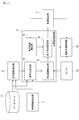
- FIG. 1 is a block diagram of a driving support apparatus according to an embodiment of the present invention.
- the driving support device according to the present embodiment is a device that is mounted on a vehicle and supports driving when changing lanes.
- the driving support device includes a ROM (Read Only Memory) in which various programs are stored, a CPU (Central Processing Unit) as an operation circuit for executing the programs stored in the ROM, and a RAM that functions as an accessible storage device. (Random Access Memory).
- ROM Read Only Memory
- CPU Central Processing Unit
- RAM Random Access Memory
- the driving support device includes a driving support control unit 10, a database 11, and a sensor 12.
- the database 11 records map data.
- Map data is map information such as link data and node data.
- the map data includes information on travel lanes and information for restricting vehicle travel.
- the travel lane information is information on a lane such as a right turn lane, a straight lane, or a left turn lane among the plurality of lanes.
- the information is the main line and the merging lane that merges with the main line.
- information on the main line and a diversion lane that diverges from the main line are also recorded in the map database.
- the sensor 12 is a sensor for detecting the surrounding situation of the own vehicle, and is a camera, a millimeter wave, a radar, or the like.
- the sensor 12 is provided in the own vehicle.
- the driving support control unit 10 controls the driving of the host vehicle based on the detection value of the sensor 12. For example, the driving support control unit 10 recognizes the situation ahead of the host vehicle using the sensor 12, and controls the vehicle to decelerate when the distance between the host vehicle and the preceding vehicle is shorter than a predetermined distance. To do. In addition, the driving support control unit 10 controls the vehicle to stop behind the preceding vehicle in order to avoid a collision with the preceding vehicle.
- the control by the driving support control unit 10 may not only decelerate, but may also automatically control driving such as changing lanes or turning left and right.
- the driving support device includes a vehicle information detection unit 1, a travel route calculation unit 2, a target point setting unit 3, and a vehicle speed estimation unit 7 as functional blocks for setting a lane change pattern suitable for driving support as described above.
- the target point setting unit 3 includes a reference point setting unit 4, a detection range setting unit 5, and a completion point setting unit 6.
- Vehicle information detection unit 1 detects vehicle information of the own vehicle.
- the vehicle information includes position information of the own vehicle.
- the vehicle information detection unit 1 has a function such as GPS and measures the current position of the vehicle.
- the travel route calculation unit 2 acquires vehicle information from the vehicle information detection unit 1 and calculates a travel route from the current location of the vehicle to the destination while referring to the map data.
- the target point setting unit 3 sets the location where the vehicle changes lanes on the travel route. Further, the target point setting unit 3 sets a target point for changing the lane so that the vehicle can detect the surrounding environment using the sensor 12 after the lane change when the own vehicle changes the lane. .
- the reference point setting unit 4 When the reference point setting unit 4 obtains the travel route from the travel route calculation unit 2, the reference point setting unit 4 refers to the map data recorded in the database 11, and the own vehicle is in the lane on the travel route from the current position of the own vehicle to the destination.
- a location where the change must be made (hereinafter also referred to as a lane change location) is set.
- the lane change point is, for example, when traveling on a two-lane road and turning right at the previous intersection, or entering the main line at the junction of the expressway.
- the lane change location may be a location where the vehicle is restricted by the shape of the road when traveling along the travel route.
- the reference point setting unit 4 sets a lane change point from road information included in the map data.
- the reference point setting unit 4 sets a reference point on the travel route as a reference when setting a lane change completion point to be described later.
- the reference point is located in front of the lane change point in the traveling direction of the host vehicle. Details of the reference point will be described later.
- the reference point setting unit 4 sets the lane change location and the reference point on the travel route based on the position of the host vehicle and the map information.
- the detection range setting unit 5 sets the detection range of the sensor 12.
- the completion point setting unit 6 sets a point where the vehicle should complete the lane change (hereinafter also referred to as a lane change completion point) based on the detection range of the sensor 12 and the reference point set by the reference point setting unit 4. .
- the target point setting unit 3 sets the lane change point, the reference point, and the lane change completion point as various target points, and outputs them to the vehicle speed estimation unit 7 and the driving support control unit 10.
- the vehicle speed estimation unit 7 estimates the vehicle speed at which the host vehicle should travel at the lane change completion point based on the distance from the lane change completion point to the reference point and the deceleration from the lane change completion point to the reference point.
- FIG. 2 is a flowchart showing a control flow of the driving support device.
- a specific example is when the host vehicle is traveling on a three-lane road and turns right at the previous intersection.
- FIG. 3 is a diagram showing a road layout showing this specific example. As shown in FIG. 3, the host vehicle is currently driving in lane A, and in order to make a right turn at the previous intersection, lane A is changed to lane (passing lane) B, and lane B is changed to lane C. I have to make changes. A part of the lane C is a section in which lane change is prohibited.
- the vehicle information detection unit 1 detects the position of the vehicle as the current vehicle information of the own vehicle.
- the position of the vehicle is detected by a combination of GPS (Global Positioning System), a gyro sensor, a vehicle speed sensor, and the like.
- GPS Global Positioning System
- the position of the vehicle is not limited to the current location of the stopped vehicle, but may be the current location of the running vehicle.
- step S2 the travel route calculation unit 2 calculates the travel route to the destination based on the current location of the vehicle.
- the travel route is a route from which the vehicle will travel.
- a car navigation system is used to calculate the travel route.
- the calculation of the travel route does not need to obtain the lane to be traveled, and may be performed by going straight on the route or going straight at the intersection, turning right, turning left.
- the reference point setting unit 4 specifies an intersection on the travel route based on the current position of the vehicle and the map information. Further, the reference point setting unit 4 sets a lane change point based on the identified intersection and the travel route.
- the reference point setting unit 4 can specify that the road connected to the intersection is three lanes from the map information, and can specify that the own vehicle turns right at the intersection from the travel route. Therefore, the reference point setting unit 4 can specify that a lane change is required before the intersection in order for the vehicle to travel through the intersection.
- the reference point setting unit 4 can specify a place where a lane change is necessary from the layout of the road leading to the intersection. Thereby, the reference point setting unit 4 sets the place as a lane change place while specifying a place where the lane change is necessary based on the road structure indicated by the map information.
- the reference point setting unit 4 identifies each intersection and identifies the lane change location from the road information and the travel route connected to the intersection. Thereby, the reference point setting unit 4 identifies all intersections on the travel route and lane change points.
- step S4 the reference point setting unit 4 sets a reference point based on the map data.
- the reference point is the position of a feature that affects the traveling of the vehicle when assisting the traveling of the host vehicle.
- the travel of the host vehicle is restricted by the lane change prohibition section 101 and the line 102 that prohibits the lane change.
- the lane change prohibition section 101 is drawn with a plurality of oblique lines on the road surface.
- the right turn lane is a short distance lane before the intersection, and the right turn lane is the right lane with respect to the overtaking lane.
- the lane change prohibition section 101 is shown.
- the line 102 is drawn with an orange solid line.
- the lane change is prohibited 30 meters before the intersection, and the line 102 represents the lane change prohibition.
- the reference point setting unit 4 specifies the end of the lane change prohibited section 101 as a reference point in the traveling direction of the host vehicle.
- This reference point represents a tip portion where a right turn lane starts when the host vehicle travels along a travel route (hereinafter, the reference point is also referred to as a right turn lane start end).
- the reference point setting unit 4 specifies the start end of the line 102 as a reference point in the traveling direction of the host vehicle.
- This reference point is the tip of a section where lane change is prohibited when the vehicle travels in a right turn lane (hereinafter also referred to as a lane change prohibited end).
- the reference point setting unit 4 sets a reference point closer to the own vehicle as a reference point to be controlled.
- the driving support control unit 10 When the driving support control unit 10 supports driving on the travel route, the driving support control unit 10 detects the lane change prohibition section 101 by the sensor 12 after changing the lane from the driving lane to the overtaking lane.
- the driving support control unit 10 detects the line 102 by the sensor 12 after changing the lane from the overtaking lane to the right turn lane. That is, the reference point set by the reference point setting unit 4 also corresponds to a position that should be detected by the sensor 12 for traveling after a lane change.
- the detection range of the sensor (for example, the wide angle of the camera) is set so that the sensor 12 can detect the reference point (right turn lane start end) when changing the lane.
- the detection range setting unit 5 sets the detection range of the sensor 12.
- the sensor 12 includes a plurality of sensors such as a millimeter wave, a radar, and a laser in addition to the camera, and the sensors 12 are provided so as to complement the detection range.
- the detection range (detection distance) of the sensor is 200 meters for millimeter waves, several hundred meters for radar, 100 meters for lasers, and several tens of meters for cameras.
- the detection range of the sensor is specified not only by distance but also by angle. In the millimeter wave, the detection range is relatively narrow, but the camera can be selected to narrow or widen the detection range depending on the wide angle of the lens.
- the maximum detection range by those sensors may be the detection range of the sensor, or the minimum detection The range may be the detection range of the sensor.
- the imaging range of the camera will be described as the detection range of the sensor (for example, 50 meters).
- step S6 the completion point setting unit 6 sets the change completion point at a position where the length of the detection range is away from the reference point (right turn lane prohibited end) end in the direction opposite to the traveling direction of the own vehicle.
- the length of the detection range is the length of a line along the traveling direction of the vehicle in the detection range.
- 4 and 5 are diagrams showing the layout of the road, showing the same layout as FIG.
- the lane change completion point is set to a position that approaches the vehicle by the detection range with respect to the reference point (right turn lane prohibited end).
- the driving support control unit 10 uses the sensor 12 to change the reference point (right turn) after changing the lane from the traveling lane to the passing lane.
- a lane change completion point is set at a position where a lane prohibited end) can be detected.
- the reference point (right turn lane prohibited) immediately after the vehicle changes lane from the driving lane to the overtaking lane. Edge) is not included in the detection range. Assuming the point where the vehicle running in the overtaking lane starts to detect the reference point (right turn lane prohibited end) as the detection start point, if the distance between the lane change completion point and the detection start point is long, After the vehicle has changed its lane, it will travel in the overtaking lane for a long time. Such traveling is not desirable.
- the sensor 12 changes the lane from the traveling lane to the overtaking lane, and then the reference point ( The timing to detect the right turn lane prohibited end is delayed. For example, as shown in FIG. 5, when a vehicle waiting for a right turn at an intersection protrudes from the right turn lane, driving assistance for changing the lane is not executed until the vehicle reaches the lane change completion point. Then, if the vehicle completes the lane change at the lane change point according to the driving assistance, the inter-vehicle distance from the own vehicle to the preceding vehicle is short, and the own vehicle needs to rapidly decelerate.
- the position of the lane change completion point is set so as to coincide with the timing at which the sensor 12 detects the reference point (right turn lane prohibited end) after the own vehicle has changed from the driving lane to the overtaking lane. ing. Therefore, after completing the lane change, it is possible to grasp the road environment near the reference point (right turn lane prohibited end) by making the most of the sensor detection range. Moreover, the situation of the right turn lane (for example, the situation where the vehicle waiting for the right turn from the right turn lane as shown in FIG. 5) can be quickly confirmed, and the host vehicle can flexibly cope with the preceding vehicle. .
- step S7 the vehicle speed estimation unit 7 estimates the vehicle speed at the reference point (right turn lane prohibited end) based on the map data.
- the vehicle speed at the reference point (right turn lane prohibited end) is statutory due to the road structure near the reference point (right turn lane prohibited end). The speed is lower than the speed.
- the host vehicle enters the right turn lane from the reference point (right turn lane prohibited end) and then decelerates in preparation for a right turn at the intersection.
- the vehicle speed at the reference point (right turn lane prohibited end) is lower. For example, assuming that the vehicle is jammed in the right turn lane and assuming that the vehicle stops before entering the right turn lane, the vehicle speed estimation unit 7 sets the vehicle speed at the reference point (right turn lane prohibited end) to 0 [ km / h]. Also, for example, assuming that the vehicle is smoothly entering the right turn lane on the assumption that the vehicle is not jammed in the right turn lane, the vehicle speed estimation unit 7 is a road with a legal speed of 60 [km / h]. The vehicle speed is estimated to be 20 to 30 [km / h].
- the vehicle speed estimation unit 7 estimates the vehicle speed while assuming the traffic environment near the reference point (right turn lane prohibited end). In the following description, it is assumed that the vehicle speed at the reference point (right turn lane prohibited end) is estimated at 0 [km / h].
- step S8 the vehicle speed estimation unit 7 calculates a deceleration pattern from the change completion point to the reference point (right turn lane prohibited end) based on the estimated vehicle speed.
- the deceleration pattern is represented by a deceleration of the vehicle speed. For example, in the case of sufficiently slow deceleration, the deceleration is 0.15G.
- the deceleration pattern may be a substantially constant deceleration, or the deceleration may be changed according to the speed.
- the vehicle speed estimation unit 7 estimates a vehicle speed (hereinafter also referred to as a target vehicle speed) that the host vehicle should travel at the vehicle speed change point based on the vehicle speed at the reference point (right turn lane prohibited end) and the deceleration pattern. To do.
- the target vehicle speed is a target value of the vehicle speed that should be reached when the lane change is completed.
- the target vehicle speed is v [km / h] and is decelerated using a constant deceleration (0.15G) to reach the reference point (the right turn lane prohibited end) from the lane change completion point.
- time be t.
- the length (d [m]) of the detection range of the sensor 12 is represented by the formula (1).
- Equation (2) is established between the speed (v) and time (t) at the lane change completion point.
- the detection range is several tens of meters.
- the vehicle speed estimation unit 7 calculates the legal speed as the target vehicle speed when the vehicle speed calculated by the above calculation formula is larger than the legal speed.
- step S10 the driving support control unit 10 performs driving support control so that the vehicle completes the lane change at the lane change completion point and the vehicle speed at the time of completion of the lane change becomes the target vehicle speed.
- the driving support control at the time of lane change is the acceleration and steering of the vehicle so that the vehicle speed at the lane change completion point becomes the target vehicle speed while the lane change is completed at the lane change completion point. , Braking and so on.
- the lane change completion point is set based on the detection range of the sensor. Therefore, when driving assistance is performed so that the lane change is completed at the lane change completion start point, the sensor 12 can easily detect an environmental change near the reference point of the lane change destination. As a result, an appropriate lane change can be realized while preventing a sudden lane change or a sudden deceleration after completion of the lane change.
- the lane change point and the reference point are set on the travel route based on the position of the host vehicle and the map information, and the lane change is performed based on the detection range of the sensor 12 and the position of the reference point. Set as completion point.
- the sensor 12 can easily detect the environmental change on the travel route to the reference point, so that the lane change can be performed at an appropriate place.
- the position to be detected by the sensor 12 is set as a reference point for traveling after the lane change at the lane change completion point. Therefore, when the lane change is performed at the lane change completion point, the sensor 12 can easily detect the environmental change around the reference point, and thus the lane change can be performed at an appropriate place.
- the change completion point is set at a position that is at least the length of the detection range with respect to the reference point in the direction opposite to the traveling direction of the host vehicle.
- the vehicle speed at which the host vehicle should travel at the lane change completion point is estimated based on the distance from the lane change completion point to the reference point and the deceleration from the lane change completion point to the reference point.
- a lane change place necessary for traveling at an intersection is set as a lane change place. This enables driving assistance so that an appropriate lane change can be performed when a lane change is required to travel an intersection.
- the reference point is set based on the road structure indicated by the map information. Therefore, since the reference point is set based on the characteristics of the universal road structure such as the lane and the road shape, a typical lane change in the route scheduled for the lane change can be executed.
- the starting point when the lane is changed after completion of the lane change at the lane change completion point (corresponding to the start point of the right turn lane) is used as the reference point. Accordingly, it is possible to realize lane change that allows smooth running while observing traffic rules.
- the detection range of the sensor 12 is set according to the typical value of the sensor 12. Thereby, after grasping
- the reference point is the right turn lane start end, but may be a lane change prohibition end.
- FIG. 6 is a diagram for explaining control when the lane change prohibition end is used as a reference point, and is a road layout.
- the lane change prohibition section 101 does not exist compared to the layout of FIG. The rest of the layout is the same as in FIG.
- the same control as described above is executed while the lane change prohibition end is set as the reference point.
- the driving support device may calculate the travel route not only when the vehicle is traveling, but also when the vehicle is stopped.
- the vehicle information detection unit 1 corresponds to the “position measurement unit” of the present invention
- the sensor 12 corresponds to the “detection unit” of the present invention
- the target point setting unit 3 corresponds to the “setting unit” of the present invention
- the vehicle speed estimation unit 7 corresponds to “vehicle speed estimation means” of the present invention.
- FIG. 7 is a block diagram of a driving support apparatus according to another embodiment of the invention. This example differs from the first embodiment described above in that it includes a travel distance calculation unit 8. Other configurations are the same as those in the first embodiment described above, and the description thereof is incorporated.
- the target point setting unit 3 has a travel distance calculation unit 8 in addition to the reference point setting unit 4.
- the travel distance calculation unit 8 calculates the travel distance of the host vehicle that moves to the reference point after the lane change of the host vehicle based on the vehicle speed of the host vehicle after the vehicle speed change and the deceleration from the lane change point to the reference point. Calculate.
- the travel distance calculation unit 8 outputs the calculation result to the completion point setting unit 6.
- FIG. 8 is a flowchart showing a control flow of the driving support apparatus.
- step S11 to step S14 is the same as the control flow from step S1 to step S4 of the first embodiment.
- the detection range setting unit 5 acquires an error in the detection range of the sensor 12.
- the sensor 12 includes a plurality of sensors having different characteristics such as millimeter waves, radars, lasers, and cameras. Lasers can achieve very high ranging and detection accuracy (for example, 1% error with respect to distance) based on the signal and measurement method used.
- the distance can be measured by a technique called motion stereo using a time series recognition result of one camera.
- the detection performance and ranging performance of the camera are low. That is, the error included in the detection result of the sensor 12 can be defined by a unique value depending on the device used as the sensor and the recognition method. As described above, the performance varies depending on the various sensors constituting the sensor 12.
- the detection range setting unit 5 grasps the sensor 12 detection error based on the performance of each sensor.
- the detection range setting unit 5 calculates the certainty of the detection range of the sensor 12.
- Various sensors such as cameras and radars constituting the sensor 12 differ not only in error but also in certainty.
- the certainty factor is an index indicating whether or not the detection result can be confirmed as a correct result.
- the certainty factor included in the detection result of the sensor is a value that varies depending on the situation. For example, since the movement process of the target object to be detected can be grasped by analyzing time-series data during traveling, the detection range setting unit 5 calculates the certainty factor based on the movement process of the target object. Can do. In addition, the detection range setting unit 5 uses the sensor 12 to grasp the surrounding situation of the currently traveling vehicle. The ambient condition detected by the sensor 12 does not change immediately.
- the detection range setting unit 5 can calculate the certainty factor by comparing the previous detection result with the current detection result and determining the continuity of the surrounding situation.
- the detection range setting unit 5 corrects the detection range of the sensor 12 based on the error and the certainty factor.
- the detection range setting unit 5 stores a map indicating a correspondence relationship between the error, the certainty factor, and the correction distance.
- FIG. 9 is a graph showing the correspondence between maps. As a characteristic of the map, the larger the error, the longer the correction distance, and the lower the certainty, the longer the correction distance.
- the correction distance is a correction value for correcting the detection range by adding to the length of the detection range.
- the detection range is corrected so that the detection range is widened based on the low confidence and the size of the error.
- the detection range setting unit 5 calculates a correction distance corresponding to the error and certainty factor of the sensor 12 while referring to the map.
- the detection range setting unit 5 corrects the detection range by adding the correction distance to the detection range.
- the corrected detection range is also referred to as a corrected detection range.
- step S18 the vehicle speed estimation unit 7 estimates the vehicle speed at the reference point and the vehicle speed when the lane is changed.
- the vehicle speed of the reference point is the same as the estimation method in step S7 according to the first embodiment.
- the lane change completion point is not fixed, and the target vehicle speed is not estimated. Therefore, the vehicle speed estimation unit 7 calculates the legal speed as the vehicle speed when changing the vehicle speed.
- the vehicle speed estimation unit 7 sets the vehicle speed lower than the legal speed at the time of the vehicle speed change. You may calculate as a vehicle speed.
- the travel distance calculation unit 8 calculates the travel distance to move to the reference point after changing the lane of the own vehicle.
- the travel distance is a travel distance of the host vehicle that is required until the vehicle speed at the time of lane change becomes the reference point vehicle speed at a constant deceleration.
- the vehicle speed of the lane change is a vehicle speed (for example, a legal speed) estimated by the vehicle speed estimation unit 7.
- the constant deceleration is determined in advance by assuming a deceleration pattern of the own vehicle, for example, when the own vehicle slowly decelerates.
- the travel distance d is expressed by the equation (4) using the above equation (3). It is expressed in
- v is the vehicle speed when the lane is changed.
- step S20 the completion point setting unit 6 compares the travel distance and the correction detection range.
- the completion point setting unit 6 is a position that is spaced from the reference point in the direction opposite to the traveling direction of the host vehicle.
- step S22 the completion point setting unit 6 determines the correction detection range with respect to the reference point in the direction opposite to the traveling direction of the host vehicle. Set the lane change completion point at the position where the minute is left.
- FIGS. 10 and 11 are diagrams for explaining lane change on a three-lane road, and show a road layout.
- the end of the three-lane road is connected to the intersection.
- the own vehicle changes lane B to lane C.
- sensor 12 a sensor with a small error and a high certainty (typical value of the detection range is 50 meters) is referred to as sensor 12.
- the reference point is the lane change prohibition end of the line 102.
- the completion point setting unit 6 sets a lane change completion point based on the travel distance.
- the completion point setting unit 6 sets a lane change completion point based on the detection range.
- step S23 the vehicle speed estimation unit 7 estimates the target vehicle speed at the vehicle speed change point based on the vehicle speed at the reference point (right turn lane prohibited end) and the deceleration pattern.
- the vehicle speed estimation unit 7 sets the vehicle speed estimated in the control flow in step S18 as the target vehicle speed.
- the vehicle speed estimation unit 7 estimates the vehicle speed by the same method as the control flow of step S9 according to the first embodiment.
- step S24 the driving support control unit 10 performs driving support control so that the vehicle completes the lane change at the lane change completion point, and the vehicle speed at the time when the lane change is completed becomes the target vehicle speed.
- the lane change completion point is taken into consideration while taking into account the error or certainty of the detection range of the sensor 12. Is set. Therefore, when driving assistance is performed so that the lane change is completed at the lane change completion start point, a sudden lane change or a sudden deceleration after the lane change is completed can be prevented. Further, the lane change completion point is set based on the comparison result while comparing the detection range of the sensor 12 with the travel distance of the host vehicle traveling to the reference point after the lane change of the host vehicle. Thereby, the behavior of the vehicle in the lane change can be made smooth.
- the detection range is corrected based on the performance of the sensor. Then, a lane change completion point is set based on the detection range of the sensor 12 after correction. Thereby, the lane change completion point can be determined in consideration of the uncertainty of the sensor 12.
- the travel distance is calculated by calculating the travel distance to the reference point after the lane change of the host vehicle based on the vehicle speed after the lane change of the host vehicle and the deceleration from the lane change point to the reference point. If it is longer than the length of the range, a lane change completion point is set at a position at least a distance away from the reference point in the direction opposite to the traveling direction. Thereby, the behavior of the vehicle in the lane change can be made smooth. In addition, since the distance between the lane change point and the reference point becomes longer than the length of the detection range of the sensor 12, it is possible to easily change the lane while compensating for the shortage of the length of the detection range.
- the detection range setting unit 5 corresponds to the “correction unit” of the present invention.
- FIG. 12 is a block diagram of a driving assistance apparatus according to another embodiment of the invention.
- the point which has the congestion state estimation part 9 differs with respect to 1st Embodiment mentioned above.
- Other configurations are the same as those of the first embodiment described above, and the descriptions of the first and second embodiments are incorporated as appropriate.
- the driving support device includes a congestion state estimation unit 9 in addition to the vehicle information detection unit 1.
- the congestion state estimation unit 9 estimates the congestion state of the travel route on which the vehicle travels before the vehicle travels on the lane change point.
- the congestion state estimation unit 9 obtains congestion information from outside the vehicle by radio or the like, or detects the state of other vehicles traveling around the vehicle using the sensor 12 to detect the congestion state using communication. presume.
- the estimation range of the congestion state estimation unit 9 is a route from at least a lane change point to a reference point in the travel route.
- the congestion state estimation unit 9 outputs the estimation result to the detection range setting unit 5.
- FIG. 13 is a flowchart showing a control flow of the driving support apparatus.
- control flow of steps S31 to S35 is the same as the control flow of steps S1 to S5 of the first embodiment.
- step S36 the congestion state estimation unit 9 estimates the congestion state.
- the congestion state estimation unit 9 acquires the congestion state by communication
- the congestion state estimation unit 9 acquires the congestion information of the road on which the vehicle is scheduled to travel by using, for example, VICS (registered trademark) (Vehicle Information and Communication System). To do.
- VICS registered trademark
- the congestion state estimation unit 9 can also estimate the congestion state using the sensor 12 as follows. For example, when the surroundings of the host vehicle are congested and the detection range of the sensor 12 is blocked by another vehicle traveling in front of the host vehicle (see FIG. 13 described later), the length of the detection range of the sensor Corresponds to the inter-vehicle distance to the other vehicle ahead. Therefore, the congestion state estimation unit 9 calculates the inter-vehicle distance from the other vehicle using the speed of the own vehicle while detecting the other vehicle ahead by the sensor 12. Then, the inter-vehicle distance is compared with the length (typical value) of the detection range, and when the inter-vehicle distance is shorter than the detection range, the congestion state estimation unit 9 determines that it is congested.
- the congestion state estimation part 9 can estimate a congestion state from the vehicle speed of the own vehicle and the detection result of the sensor 12.
- step S37 the detection range setting unit 5 corrects the detection range according to the congestion state.
- the relationship between the detection range of the sensor 12 and the congestion state will be described with reference to FIG. FIG. 14 shows a state where the traveling route of the own vehicle is congested, and shows a state where another vehicle is traveling in front of the own vehicle.
- traveling routes are mixed and other vehicles are traveling in front of the host vehicle.
- the substantial detection range of the sensor 12 becomes narrower than the original detection range, and the detection range is the other vehicle. Until the back. Therefore, it becomes difficult to detect the situation ahead of the host vehicle using the sensor 12. The detection accuracy of the sensor 12 is lowered.
- the detection range setting unit 5 stores a map indicating the correspondence between the congestion state and the correction distance.
- FIG. 15 is a graph showing the correspondence between maps. As the characteristics of the map, the greater the congestion state, the longer the correction distance, and the lower the certainty factor, the longer the correction distance.
- the correction distance is a correction value for correcting the detection range by adding to the length of the detection range.
- the congestion state is shown as “large” as the lane becomes more congested.
- the substantial detection range of the sensor 12 is likely to be shortened, so that the detection accuracy of the object using the sensor 12 is reduced when performing driving support control. Therefore, in order to compensate for the decrease in the detection accuracy of the detection range setting unit 5, the correction is performed so that the detection range is widened by adding the correction distance to the detection range.
- the detection range setting unit 5 calculates a correction distance corresponding to the estimated congestion state while referring to the map. Then, the detection range setting unit 5 corrects the detection range by adding the correction distance to the detection range.
- step S38 the completion point setting unit 6 sets the change completion point at a position where the length of the detection range corrected with respect to the reference point end is left in the direction opposite to the traveling direction of the host vehicle.
- the control flow of steps S39 to S42 is the same as the control flow of steps S1 to S5 of the first embodiment.
- the lane change completion point is set in consideration of the congestion state of the travel route. Therefore, when driving assistance is performed so that the lane change is completed at the start point of completion of the lane change, an appropriate Lane change can be realized.
- the congestion state of the travel route on which the vehicle travels is estimated, and the detection range of the sensor 12 is corrected based on the congestion state.
- the lane change completion point can be determined so as to compensate for a decrease in the detection accuracy of the object using the sensor 12 due to a traffic jam or the like.
- the congestion state is estimated based on the situation around the vehicle detected by the sensor 12. Thereby, an actual congestion state can be estimated.
- the traffic jam information is acquired by communication, and the congestion state is estimated based on the traffic jam information. Thereby, the congestion state can be estimated without using the sensor 12.
- the above-described congestion state estimation unit 9 corresponds to the “estimator” of the present invention.
Landscapes
- Engineering & Computer Science (AREA)
- Radar, Positioning & Navigation (AREA)
- Remote Sensing (AREA)
- Automation & Control Theory (AREA)
- Physics & Mathematics (AREA)
- General Physics & Mathematics (AREA)
- Transportation (AREA)
- Mechanical Engineering (AREA)
- Chemical & Material Sciences (AREA)
- Combustion & Propulsion (AREA)
- Computer Vision & Pattern Recognition (AREA)
- Aviation & Aerospace Engineering (AREA)
- Traffic Control Systems (AREA)
- Navigation (AREA)
- Steering Control In Accordance With Driving Conditions (AREA)
Abstract
Description
《第1実施形態》 Hereinafter, embodiments of the present invention will be described with reference to the drawings.
<< First Embodiment >>


図7は、発明の他の実施形態に係る運転支援装置のブロック図である。本例では上述した第1実施形態に対して、走行距離演算部8を有する点が異なる。これ以外の構成は上述した第1実施形態と同じであり、その記載を援用する。 << Second Embodiment >>
FIG. 7 is a block diagram of a driving support apparatus according to another embodiment of the invention. This example differs from the first embodiment described above in that it includes a travel

図12は、発明の他の実施形態に係る運転支援装置のブロック図である。本例では上述した第1実施形態に対して、混雑状態推定部9を有する点が異なる。これ以外の構成は上述した第1実施形態と同じであり、第1実施形態及び第2実施形態の記載を適宜、援用する。 << Third Embodiment >>
FIG. 12 is a block diagram of a driving assistance apparatus according to another embodiment of the invention. In this example, the point which has the congestion
2…走行経路演算部
3…目標地点設定部
4…基準点設定部
5…検出範囲設定部
6…完了地点設定部
7…車速推定部
8…走行距離演算部
9…混雑状態推定部
10…運転支援制御部
11…データベース
12…センサ DESCRIPTION OF
Claims (14)
- 自車が車線変更する際の運転を支援する運転支援装置において、
前記自車の位置を測定する位置測定手段と、
前記自車に設けられ、前記自車の周囲状況を検出する検出手段と、
地図情報を記録するデータベースと、
前記自車の位置と前記地図情報に基づき、前記自車が車線変更しなければならない箇所と、前記自車の進行方向で前記箇所よりも前方に位置する基準点とを前記自車の走行経路上に設定する設定手段とを備え、
前記設定手段は、前記検出手段の検出範囲と前記基準点の位置に基づき、前記自車が車線変更を完了すべき地点を車線変更完了地点として設定する
ことを特徴とする運転支援装置。 In a driving support device that supports driving when the vehicle changes lanes,
Position measuring means for measuring the position of the vehicle;
A detecting means provided in the own vehicle for detecting a surrounding situation of the own vehicle;
A database that records map information;
Based on the position of the host vehicle and the map information, a location where the host vehicle has to change lanes and a reference point positioned ahead of the location in the traveling direction of the host vehicle are travel routes of the host vehicle. And setting means for setting above,
The setting means sets a point where the own vehicle should complete a lane change as a lane change completion point based on the detection range of the detection means and the position of the reference point. - 請求項1記載の運転支援装置において、
前記設定手段は、
前記車線変更完了地点における車線変更の後の走行のために、前記検出手段で検出すべき位置を、前記基準点として設定する
ことを特徴とする運転支援装置。 The driving support device according to claim 1,
The setting means includes
A driving support apparatus, wherein a position to be detected by the detection means is set as the reference point for traveling after a lane change at the lane change completion point. - 請求項1又は2記載の運転支援装置において、
前記設定手段は、
前記進行方向と反対側の方向で、前記基準点に対して少なくとも前記検出範囲の長さ分を空けた位置に、前記変更完了地点を設定する
ことを特徴とする運転支援装置。 In the driving assistance device according to claim 1 or 2,
The setting means includes
The driving support device, wherein the change completion point is set at a position that is at least the length of the detection range with respect to the reference point in a direction opposite to the traveling direction. - 請求項1~3のいずれか一項に記載の運転支援装置において、
前記車線変更完了地点から前記基準点までの距離、及び、前記車線変更完了地点から前記基準点までの減速度に基づき、前記自車が前記車線変更完了地点で走行すべき車速を推定する車速推定手段を備える
ことを特徴とする運転支援装置。 In the driving support device according to any one of claims 1 to 3,
Based on the distance from the lane change completion point to the reference point and the deceleration from the lane change completion point to the reference point, the vehicle speed estimation for estimating the vehicle speed at which the host vehicle should travel at the lane change completion point A driving support device comprising means. - 請求項1~4のいずれか一項に記載の運転支援装置において、
前記設定手段は、
前記地図情報で示される交差点、合流地点、分流地点のいずれか一つの地点を特定し、特定された地点を走行するために必要な車線変更の場所を、前記車線変更箇所に設定する
ことを特徴とする運転支援装置。 In the driving support device according to any one of claims 1 to 4,
The setting means includes
Identifying any one of the intersections, junctions, and branch points shown in the map information, and setting the lane change location necessary to travel the specified point in the lane change point A driving support device. - 請求項1~5のいずれか一項に記載の運転支援装置において、
前記設定手段は、
地図情報で示される道路の構造に基づいて前記基準点を設定する
ことを特徴とする運転支援装置。 In the driving support device according to any one of claims 1 to 5,
The setting means includes
A driving support device, wherein the reference point is set based on a road structure indicated by map information. - 請求項1~6のいずれか一項に記載の運転支援装置において、
前記設定手段は、
前記地図情報で示される車線変更禁止区間の開始端、又は、前記車線変更完了地点における車線変更の完了後に車線を変更するときの開始端を、前記基準点に設定する
ことを特徴とする運転支援装置。 The driving support device according to any one of claims 1 to 6,
The setting means includes
Driving assistance characterized in that the reference point is set as the starting point of the lane change prohibition section indicated by the map information, or the starting point when changing the lane after completion of the lane change at the lane change completion point. apparatus. - 請求項1~7のいずれか一項に記載の運転支援装置において、
前記検出範囲は、前記地物検出手段の典型値に基づいて設定されている
ことを特徴とする運転支援装置。 The driving support device according to any one of claims 1 to 7,
The driving support device, wherein the detection range is set based on a typical value of the feature detection means. - 請求項1~8のいずれか一項に記載の運転支援装置において、
前記検出範囲を補正する補正手段を備え、
前記設定手段は、前記補正手段により補正された後の前記検出範囲に基づき、前記車線変更完了地点を設定する
ことを特徴とする運転支援装置。 The driving support device according to any one of claims 1 to 8,
A correction means for correcting the detection range;
The driving support device according to claim 1, wherein the setting means sets the lane change completion point based on the detection range corrected by the correction means. - 請求項9に記載の運転支援装置において、
前記補正手段は、前記検出手段の性能に基づいて前記検出範囲を補正する
ことを特徴とする運転支援装置。 The driving support device according to claim 9, wherein
The driving support device, wherein the correction unit corrects the detection range based on the performance of the detection unit. - 請求項9に記載の運転支援装置において、
前記自車が走行する走行経路の混雑状態を推定する推定手段を備え、
前記補正手段は、前記混雑状態に基づいて前記検出範囲を補正する
ことを特徴とする運転支援装置。 The driving support device according to claim 9, wherein
Comprising estimation means for estimating a congestion state of a travel route on which the host vehicle travels,
The driving support device, wherein the correcting unit corrects the detection range based on the congestion state. - 請求項11に記載の運転支援装置において、
前記推定手段は、前記検出手段により検出した前記自車の周囲の状況に基づいて、前記混雑状態を推定する
ことを特徴とする運転支援装置。 The driving support apparatus according to claim 11,
The driving means according to claim 1, wherein the estimating means estimates the congestion state based on a situation around the vehicle detected by the detecting means. - 請求項11に記載の運転支援装置において、
前記推定手段は、通信により渋滞情報を取得し、前記渋滞情報に基づいて前記混雑状態を推定する
ことを特徴とする運転支援装置。 The driving support apparatus according to claim 11,
The driving means according to claim 1, wherein the estimation means acquires traffic jam information by communication and estimates the congestion state based on the traffic jam information. - 請求項1~13のいずれか一項に記載の運転支援装置において、
前記設定手段は、
前記進行方向と反対側の方向で、前記基準点に対して前記検出範囲の長さ分を空けた位置に、第1の車線変更完了地点を特定し、
前記自車の車線変更後の車速、車線変更した地点から前記基準点までの減速度に基づき、前記自車の車線変更後に前記基準点まで走行する前記自車の走行距離を演算し、
前記進行方向と反対側の方向で、前記基準点に対して少なくとも前記走行距離分を空けた位置に、第2車線変更地点を特定し、
前記走行距離が検出範囲の長さよりも長い場合には、前記第2車線変更地点を前記車線変更完了地点に設定する
ことを特徴とする運転支援装置。 The driving support device according to any one of claims 1 to 13,
The setting means includes
In a direction opposite to the traveling direction, a first lane change completion point is identified at a position that is spaced apart from the reference point by the length of the detection range,
Based on the vehicle speed after the lane change of the host vehicle, the deceleration from the lane change point to the reference point, the travel distance of the host vehicle traveling to the reference point after the lane change of the host vehicle,
In a direction opposite to the traveling direction, a second lane change point is identified at a position that is at least the travel distance away from the reference point,
When the travel distance is longer than the length of a detection range, the second lane change point is set as the lane change completion point.
Priority Applications (8)
| Application Number | Priority Date | Filing Date | Title |
|---|---|---|---|
| US15/520,275 US10118641B2 (en) | 2014-10-22 | 2014-10-22 | Drive assist device |
| PCT/JP2014/078123 WO2016063383A1 (en) | 2014-10-22 | 2014-10-22 | Driving assistance device |
| EP14904579.1A EP3211617B1 (en) | 2014-10-22 | 2014-10-22 | Driving assistance device |
| CN201480082809.1A CN107077791B (en) | 2014-10-22 | 2014-10-22 | Drive assistance device |
| MX2017005115A MX359044B (en) | 2014-10-22 | 2014-10-22 | Driving assistance device. |
| RU2017116734A RU2682690C2 (en) | 2014-10-22 | 2014-10-22 | Driving assistance device |
| BR112017008187-3A BR112017008187B1 (en) | 2014-10-22 | 2014-10-22 | STEERING ASSISTANCE DEVICE |
| JP2016555007A JP6323565B2 (en) | 2014-10-22 | 2014-10-22 | Driving assistance device |
Applications Claiming Priority (1)
| Application Number | Priority Date | Filing Date | Title |
|---|---|---|---|
| PCT/JP2014/078123 WO2016063383A1 (en) | 2014-10-22 | 2014-10-22 | Driving assistance device |
Publications (1)
| Publication Number | Publication Date |
|---|---|
| WO2016063383A1 true WO2016063383A1 (en) | 2016-04-28 |
Family
ID=55760452
Family Applications (1)
| Application Number | Title | Priority Date | Filing Date |
|---|---|---|---|
| PCT/JP2014/078123 WO2016063383A1 (en) | 2014-10-22 | 2014-10-22 | Driving assistance device |
Country Status (8)
| Country | Link |
|---|---|
| US (1) | US10118641B2 (en) |
| EP (1) | EP3211617B1 (en) |
| JP (1) | JP6323565B2 (en) |
| CN (1) | CN107077791B (en) |
| BR (1) | BR112017008187B1 (en) |
| MX (1) | MX359044B (en) |
| RU (1) | RU2682690C2 (en) |
| WO (1) | WO2016063383A1 (en) |
Cited By (14)
| Publication number | Priority date | Publication date | Assignee | Title |
|---|---|---|---|---|
| CN109415087A (en) * | 2016-08-29 | 2019-03-01 | 宝马股份公司 | For automating the lane change auxiliary system and method for implementing multiple lane change |
| JP2019048518A (en) * | 2017-09-08 | 2019-03-28 | 株式会社Subaru | Notification device |
| RU2683899C2 (en) * | 2016-08-26 | 2019-04-02 | Тойота Дзидося Кабусики Кайся | Information processing device and method |
| JP2019069640A (en) * | 2017-10-06 | 2019-05-09 | 本田技研工業株式会社 | Vehicle control device |
| CN109791736A (en) * | 2016-09-28 | 2019-05-21 | 本田技研工业株式会社 | Controller of vehicle |
| CN109997016A (en) * | 2016-11-26 | 2019-07-09 | 星克跃尔株式会社 | For guiding device, method, computer program and the computer readable recording medium of route |
| JP2019191722A (en) * | 2018-04-20 | 2019-10-31 | クラリオン株式会社 | Lane change support device |
| JP2019217828A (en) * | 2018-06-15 | 2019-12-26 | 本田技研工業株式会社 | Vehicle control device, vehicle control method, and program |
| WO2020003452A1 (en) * | 2018-06-28 | 2020-01-02 | 日産自動車株式会社 | Driving assistance method and driving assistance device |
| CN110663072A (en) * | 2017-05-22 | 2020-01-07 | 三菱电机株式会社 | Position estimation device, position estimation method, and position estimation program |
| US11043127B2 (en) | 2017-11-06 | 2021-06-22 | Toyota Jidosha Kabushiki Kaisha | Autonomous driving device |
| US11267468B2 (en) | 2019-03-28 | 2022-03-08 | Subaru Corporation | Automatic driving assistance apparatus |
| US11608065B2 (en) | 2018-08-23 | 2023-03-21 | Hyundai Motor Company | Method for advanced inertia drive control of vehicle |
| US11920942B2 (en) | 2016-11-26 | 2024-03-05 | Thinkware Corporation | Device, method, computer program, and computer readable-recording medium for route guidance |
Families Citing this family (26)
| Publication number | Priority date | Publication date | Assignee | Title |
|---|---|---|---|---|
| KR101750159B1 (en) * | 2015-07-01 | 2017-06-22 | 엘지전자 주식회사 | Assistance Apparatus for Driving of a Vehicle, Method thereof, and Vehicle having the same |
| WO2017017755A1 (en) * | 2015-07-27 | 2017-02-02 | 日産自動車株式会社 | Route guidance device and route guidance method |
| CN108349489B (en) * | 2015-11-06 | 2021-02-26 | 本田技研工业株式会社 | Vehicle travel control device |
| JP6524943B2 (en) * | 2016-03-17 | 2019-06-05 | 株式会社デンソー | Driving support device |
| JP6693685B2 (en) * | 2016-05-09 | 2020-05-13 | アルパイン株式会社 | Electronic device, guidance method and guidance system |
| JP6575492B2 (en) * | 2016-11-29 | 2019-09-18 | トヨタ自動車株式会社 | Automated driving system |
| JP6873259B2 (en) * | 2017-09-29 | 2021-05-19 | 日立Astemo株式会社 | Automatic operation control device and method |
| JP6941543B2 (en) * | 2017-11-17 | 2021-09-29 | 本田技研工業株式会社 | Vehicle control devices, vehicle control methods, and programs |
| US11360475B2 (en) * | 2017-12-05 | 2022-06-14 | Waymo Llc | Real-time lane change selection for autonomous vehicles |
| CN109987095B (en) * | 2018-01-02 | 2022-09-23 | 奥迪股份公司 | Driving assistance system and method |
| JP6601696B2 (en) | 2018-01-19 | 2019-11-06 | 本田技研工業株式会社 | Prediction device, prediction method, and program |
| EP3530538B1 (en) * | 2018-02-26 | 2022-11-23 | Toyota Jidosha Kabushiki Kaisha | Vehicle control system and vehicle control method |
| JP7043295B2 (en) * | 2018-03-07 | 2022-03-29 | 本田技研工業株式会社 | Vehicle control devices, vehicle control methods, and programs |
| JP7054636B2 (en) * | 2018-03-15 | 2022-04-14 | 本田技研工業株式会社 | Driving support device |
| US11572099B2 (en) | 2018-04-27 | 2023-02-07 | Honda Motor Co., Ltd. | Merge behavior systems and methods for merging vehicles |
| US11117584B2 (en) * | 2018-04-27 | 2021-09-14 | Honda Motor Co., Ltd. | Merge behavior systems and methods for mainline vehicles |
| JP6984547B2 (en) * | 2018-06-08 | 2021-12-22 | トヨタ自動車株式会社 | Lane change support system, lane change support device and lane change support method |
| US11618475B2 (en) * | 2018-07-04 | 2023-04-04 | Nissan Motor Co., Ltd. | Driving support method and driving support device |
| CN109035863B (en) * | 2018-08-09 | 2021-11-23 | 北京智行者科技有限公司 | Forced lane-changing driving method for vehicle |
| JP7218172B2 (en) * | 2018-12-25 | 2023-02-06 | フォルシアクラリオン・エレクトロニクス株式会社 | In-vehicle processing device and control method for in-vehicle processing device |
| JP7316542B2 (en) * | 2019-05-21 | 2023-07-28 | スズキ株式会社 | Vehicle running control device |
| FR3100783B1 (en) * | 2019-09-12 | 2021-08-13 | Renault Sas | Method for assisting in the choice of positioning a vehicle on a road comprising a plurality of traffic lanes |
| WO2021059601A1 (en) * | 2019-09-27 | 2021-04-01 | アイシン・エィ・ダブリュ株式会社 | Drive assistance device and computer program |
| JP2021112995A (en) | 2020-01-20 | 2021-08-05 | 本田技研工業株式会社 | Control system, control method, vehicle, and program |
| DE102022111125A1 (en) | 2022-05-05 | 2023-11-09 | Bayerische Motoren Werke Aktiengesellschaft | Method for maneuvering a vehicle on a multi-lane road with determination of a starting point of a deceleration strip and driver assistance system |
| CN117058900A (en) * | 2023-04-24 | 2023-11-14 | 深圳市赛诺杰科技有限公司 | Traffic signal lamp system based on buried signal lamp |
Citations (4)
| Publication number | Priority date | Publication date | Assignee | Title |
|---|---|---|---|---|
| JPH09178505A (en) * | 1995-12-27 | 1997-07-11 | Pioneer Electron Corp | Drive assist system |
| JP2002307976A (en) * | 2001-04-17 | 2002-10-23 | Toyota Motor Corp | Running support device |
| JP2004185504A (en) * | 2002-12-05 | 2004-07-02 | Denso Corp | Drive assist system |
| JP2005189009A (en) * | 2003-12-24 | 2005-07-14 | Aisin Aw Co Ltd | Navigation device and navigation system |
Family Cites Families (9)
| Publication number | Priority date | Publication date | Assignee | Title |
|---|---|---|---|---|
| JP3925474B2 (en) * | 2003-07-18 | 2007-06-06 | 日産自動車株式会社 | Lane change support device |
| JP4379199B2 (en) * | 2004-05-17 | 2009-12-09 | 日産自動車株式会社 | Lane change support apparatus and method |
| JP4591311B2 (en) | 2005-10-31 | 2010-12-01 | アイシン・エィ・ダブリュ株式会社 | Route guidance system and route guidance method |
| JP4753999B2 (en) * | 2006-12-18 | 2011-08-24 | 三菱電機株式会社 | Navigation device |
| JP4739400B2 (en) * | 2008-12-22 | 2011-08-03 | 日立オートモティブシステムズ株式会社 | Vehicle driving support system |
| US20120316733A1 (en) * | 2010-03-04 | 2012-12-13 | Honda Motor Co., Ltd. | Vehicle turning control device |
| JP5541103B2 (en) | 2010-11-15 | 2014-07-09 | アイシン・エィ・ダブリュ株式会社 | Travel guidance device, travel guidance method, and computer program |
| JP6241341B2 (en) * | 2014-03-20 | 2017-12-06 | アイシン・エィ・ダブリュ株式会社 | Automatic driving support device, automatic driving support method and program |
| US9538334B2 (en) * | 2015-01-15 | 2017-01-03 | GEOTAB Incorporated | Telematics furtherance visualization system |
-
2014
- 2014-10-22 CN CN201480082809.1A patent/CN107077791B/en active Active
- 2014-10-22 WO PCT/JP2014/078123 patent/WO2016063383A1/en active Application Filing
- 2014-10-22 EP EP14904579.1A patent/EP3211617B1/en active Active
- 2014-10-22 BR BR112017008187-3A patent/BR112017008187B1/en active IP Right Grant
- 2014-10-22 US US15/520,275 patent/US10118641B2/en active Active
- 2014-10-22 JP JP2016555007A patent/JP6323565B2/en active Active
- 2014-10-22 MX MX2017005115A patent/MX359044B/en active IP Right Grant
- 2014-10-22 RU RU2017116734A patent/RU2682690C2/en active
Patent Citations (4)
| Publication number | Priority date | Publication date | Assignee | Title |
|---|---|---|---|---|
| JPH09178505A (en) * | 1995-12-27 | 1997-07-11 | Pioneer Electron Corp | Drive assist system |
| JP2002307976A (en) * | 2001-04-17 | 2002-10-23 | Toyota Motor Corp | Running support device |
| JP2004185504A (en) * | 2002-12-05 | 2004-07-02 | Denso Corp | Drive assist system |
| JP2005189009A (en) * | 2003-12-24 | 2005-07-14 | Aisin Aw Co Ltd | Navigation device and navigation system |
Cited By (26)
| Publication number | Priority date | Publication date | Assignee | Title |
|---|---|---|---|---|
| RU2683899C2 (en) * | 2016-08-26 | 2019-04-02 | Тойота Дзидося Кабусики Кайся | Information processing device and method |
| US11097777B2 (en) | 2016-08-29 | 2021-08-24 | Bayerische Motoren Werke Aktiengesellschaft | Lane-change assistance system and lane-change assistance method for the automated performance of multiple lane changes |
| CN109415087A (en) * | 2016-08-29 | 2019-03-01 | 宝马股份公司 | For automating the lane change auxiliary system and method for implementing multiple lane change |
| CN109791736A (en) * | 2016-09-28 | 2019-05-21 | 本田技研工业株式会社 | Controller of vehicle |
| US11156468B2 (en) | 2016-11-26 | 2021-10-26 | Thinkware Corporation | Device, method, computer program, and computer-readable recording medium for route guidance |
| CN109997016A (en) * | 2016-11-26 | 2019-07-09 | 星克跃尔株式会社 | For guiding device, method, computer program and the computer readable recording medium of route |
| CN109997016B (en) * | 2016-11-26 | 2024-03-29 | 星克跃尔株式会社 | Apparatus, method, computer program, and computer-readable recording medium for guiding route |
| US11920942B2 (en) | 2016-11-26 | 2024-03-05 | Thinkware Corporation | Device, method, computer program, and computer readable-recording medium for route guidance |
| EP3531072A4 (en) * | 2016-11-26 | 2020-06-17 | Thinkware Corporation | Device, method, computer program and computer readable recording medium for route guidance |
| CN110663072A (en) * | 2017-05-22 | 2020-01-07 | 三菱电机株式会社 | Position estimation device, position estimation method, and position estimation program |
| CN110663072B (en) * | 2017-05-22 | 2022-03-29 | 三菱电机株式会社 | Position estimation device, position estimation method, and computer-readable storage medium |
| JP2019048518A (en) * | 2017-09-08 | 2019-03-28 | 株式会社Subaru | Notification device |
| US10994735B2 (en) | 2017-10-06 | 2021-05-04 | Honda Motor Co., Ltd. | Vehicle control device |
| JP2019069640A (en) * | 2017-10-06 | 2019-05-09 | 本田技研工業株式会社 | Vehicle control device |
| US11043127B2 (en) | 2017-11-06 | 2021-06-22 | Toyota Jidosha Kabushiki Kaisha | Autonomous driving device |
| US11645917B2 (en) | 2017-11-06 | 2023-05-09 | Toyota Jidosha Kabushiki Kaisha | Autonomous driving device |
| US11769414B2 (en) | 2017-11-06 | 2023-09-26 | Toyota Jidosha Kabushiki Kaisha | Autonomous driving device |
| US11798421B2 (en) | 2017-11-06 | 2023-10-24 | Toyota Jidosha Kabushiki Kaisha | Autonomous driving device |
| JP7042153B2 (en) | 2018-04-20 | 2022-03-25 | フォルシアクラリオン・エレクトロニクス株式会社 | Lane change support device |
| JP2019191722A (en) * | 2018-04-20 | 2019-10-31 | クラリオン株式会社 | Lane change support device |
| JP2019217828A (en) * | 2018-06-15 | 2019-12-26 | 本田技研工業株式会社 | Vehicle control device, vehicle control method, and program |
| JPWO2020003452A1 (en) * | 2018-06-28 | 2021-07-15 | 日産自動車株式会社 | Driving support method and driving support device |
| WO2020003452A1 (en) * | 2018-06-28 | 2020-01-02 | 日産自動車株式会社 | Driving assistance method and driving assistance device |
| US11661062B2 (en) | 2018-06-28 | 2023-05-30 | Nissan Motor Co., Ltd. | Driving assist method and driving assist device |
| US11608065B2 (en) | 2018-08-23 | 2023-03-21 | Hyundai Motor Company | Method for advanced inertia drive control of vehicle |
| US11267468B2 (en) | 2019-03-28 | 2022-03-08 | Subaru Corporation | Automatic driving assistance apparatus |
Also Published As
| Publication number | Publication date |
|---|---|
| RU2017116734A (en) | 2018-11-22 |
| BR112017008187A2 (en) | 2017-12-26 |
| CN107077791A (en) | 2017-08-18 |
| JPWO2016063383A1 (en) | 2017-08-03 |
| MX359044B (en) | 2018-09-13 |
| EP3211617A4 (en) | 2018-02-28 |
| JP6323565B2 (en) | 2018-05-16 |
| CN107077791B (en) | 2019-11-01 |
| RU2017116734A3 (en) | 2018-11-22 |
| EP3211617A1 (en) | 2017-08-30 |
| MX2017005115A (en) | 2017-07-14 |
| US20170320521A1 (en) | 2017-11-09 |
| RU2682690C2 (en) | 2019-03-20 |
| EP3211617B1 (en) | 2019-03-06 |
| US10118641B2 (en) | 2018-11-06 |
| BR112017008187B1 (en) | 2021-12-28 |
Similar Documents
| Publication | Publication Date | Title |
|---|---|---|
| JP6323565B2 (en) | Driving assistance device | |
| US11084489B2 (en) | Automated driving assist system | |
| US20200255027A1 (en) | Method for planning trajectory of vehicle | |
| JP6399100B2 (en) | Travel route calculation device | |
| US11204608B2 (en) | Vehicle traveling control apparatus | |
| JP6304393B2 (en) | Travel route calculation device | |
| JP5565303B2 (en) | Driving support device and driving support method | |
| CN107850456A (en) | Path guiding device and path guide method | |
| US11697416B2 (en) | Travel assistance method and travel assistance device | |
| JP7043765B2 (en) | Vehicle driving control method and equipment | |
| US20200307630A1 (en) | Vehicle control device, vehicle control method and non-transitory computer-readable medium | |
| US10665103B2 (en) | Vehicle periphery information verification device and method | |
| EP3912877B1 (en) | Driving assistance method and driving assistance device | |
| CN109425861B (en) | Device for calculating reliability of vehicle position | |
| CN110023718B (en) | Route guidance method and route guidance device | |
| KR102496819B1 (en) | Method, apparatus and system for guiding route | |
| JP7334107B2 (en) | Vehicle control method and vehicle control device | |
| JP7123645B2 (en) | Driving support method and driving support device | |
| US11353329B2 (en) | Automated driving device | |
| KR102669424B1 (en) | Apparatus for sharing positioning information of autonomous vehicle and control method thereof | |
| US20210094551A1 (en) | Method and system for determining localization of a vehicle on a road | |
| JP2022191916A (en) | Position estimation device |
Legal Events
| Date | Code | Title | Description |
|---|---|---|---|
| 121 | Ep: the epo has been informed by wipo that ep was designated in this application |
Ref document number: 14904579 Country of ref document: EP Kind code of ref document: A1 |
|
| ENP | Entry into the national phase |
Ref document number: 2016555007 Country of ref document: JP Kind code of ref document: A |
|
| WWE | Wipo information: entry into national phase |
Ref document number: 15520275 Country of ref document: US |
|
| WWE | Wipo information: entry into national phase |
Ref document number: MX/A/2017/005115 Country of ref document: MX |
|
| NENP | Non-entry into the national phase |
Ref country code: DE |
|
| REEP | Request for entry into the european phase |
Ref document number: 2014904579 Country of ref document: EP |
|
| ENP | Entry into the national phase |
Ref document number: 2017116734 Country of ref document: RU Kind code of ref document: A |
|
| REG | Reference to national code |
Ref country code: BR Ref legal event code: B01A Ref document number: 112017008187 Country of ref document: BR |
|
| ENP | Entry into the national phase |
Ref document number: 112017008187 Country of ref document: BR Kind code of ref document: A2 Effective date: 20170420 |