WO2016042811A1 - 医療用観察システム - Google Patents
医療用観察システム Download PDFInfo
- Publication number
- WO2016042811A1 WO2016042811A1 PCT/JP2015/058040 JP2015058040W WO2016042811A1 WO 2016042811 A1 WO2016042811 A1 WO 2016042811A1 JP 2015058040 W JP2015058040 W JP 2015058040W WO 2016042811 A1 WO2016042811 A1 WO 2016042811A1
- Authority
- WO
- WIPO (PCT)
- Prior art keywords
- position information
- movement
- image
- detection unit
- predetermined object
- Prior art date
Links
- 238000001514 detection method Methods 0.000 claims abstract description 51
- 238000003384 imaging method Methods 0.000 claims description 21
- 238000000034 method Methods 0.000 claims description 21
- 238000006243 chemical reaction Methods 0.000 claims description 15
- 230000005855 radiation Effects 0.000 claims 1
- 239000003550 marker Substances 0.000 description 19
- 238000003780 insertion Methods 0.000 description 16
- 230000037431 insertion Effects 0.000 description 16
- 238000010586 diagram Methods 0.000 description 14
- 210000000056 organ Anatomy 0.000 description 13
- 239000004575 stone Substances 0.000 description 8
- 210000003734 kidney Anatomy 0.000 description 7
- 102100036034 Thrombospondin-1 Human genes 0.000 description 5
- 101000659879 Homo sapiens Thrombospondin-1 Proteins 0.000 description 3
- 210000000244 kidney pelvis Anatomy 0.000 description 3
- 210000000626 ureter Anatomy 0.000 description 3
- 238000009212 extracorporeal shock wave lithotripsy Methods 0.000 description 2
- 238000002594 fluoroscopy Methods 0.000 description 2
- 239000003086 colorant Substances 0.000 description 1
- 239000000284 extract Substances 0.000 description 1
- 238000000605 extraction Methods 0.000 description 1
- 238000001125 extrusion Methods 0.000 description 1
- 230000006870 function Effects 0.000 description 1
- 239000004973 liquid crystal related substance Substances 0.000 description 1
- 238000012986 modification Methods 0.000 description 1
- 230000004048 modification Effects 0.000 description 1
- 230000001737 promoting effect Effects 0.000 description 1
- 210000003708 urethra Anatomy 0.000 description 1
Images


Classifications
-
- A—HUMAN NECESSITIES
- A61—MEDICAL OR VETERINARY SCIENCE; HYGIENE
- A61B—DIAGNOSIS; SURGERY; IDENTIFICATION
- A61B5/00—Measuring for diagnostic purposes; Identification of persons
- A61B5/48—Other medical applications
- A61B5/4836—Diagnosis combined with treatment in closed-loop systems or methods
-
- A—HUMAN NECESSITIES
- A61—MEDICAL OR VETERINARY SCIENCE; HYGIENE
- A61B—DIAGNOSIS; SURGERY; IDENTIFICATION
- A61B1/00—Instruments for performing medical examinations of the interior of cavities or tubes of the body by visual or photographical inspection, e.g. endoscopes; Illuminating arrangements therefor
- A61B1/00002—Operational features of endoscopes
- A61B1/00004—Operational features of endoscopes characterised by electronic signal processing
- A61B1/00006—Operational features of endoscopes characterised by electronic signal processing of control signals
-
- A—HUMAN NECESSITIES
- A61—MEDICAL OR VETERINARY SCIENCE; HYGIENE
- A61B—DIAGNOSIS; SURGERY; IDENTIFICATION
- A61B1/00—Instruments for performing medical examinations of the interior of cavities or tubes of the body by visual or photographical inspection, e.g. endoscopes; Illuminating arrangements therefor
- A61B1/00002—Operational features of endoscopes
- A61B1/00004—Operational features of endoscopes characterised by electronic signal processing
- A61B1/00009—Operational features of endoscopes characterised by electronic signal processing of image signals during a use of endoscope
- A61B1/000095—Operational features of endoscopes characterised by electronic signal processing of image signals during a use of endoscope for image enhancement
-
- A—HUMAN NECESSITIES
- A61—MEDICAL OR VETERINARY SCIENCE; HYGIENE
- A61B—DIAGNOSIS; SURGERY; IDENTIFICATION
- A61B1/00—Instruments for performing medical examinations of the interior of cavities or tubes of the body by visual or photographical inspection, e.g. endoscopes; Illuminating arrangements therefor
- A61B1/00002—Operational features of endoscopes
- A61B1/00043—Operational features of endoscopes provided with output arrangements
- A61B1/00045—Display arrangement
- A61B1/0005—Display arrangement combining images e.g. side-by-side, superimposed or tiled
-
- A—HUMAN NECESSITIES
- A61—MEDICAL OR VETERINARY SCIENCE; HYGIENE
- A61B—DIAGNOSIS; SURGERY; IDENTIFICATION
- A61B34/00—Computer-aided surgery; Manipulators or robots specially adapted for use in surgery
- A61B34/20—Surgical navigation systems; Devices for tracking or guiding surgical instruments, e.g. for frameless stereotaxis
-
- A—HUMAN NECESSITIES
- A61—MEDICAL OR VETERINARY SCIENCE; HYGIENE
- A61B—DIAGNOSIS; SURGERY; IDENTIFICATION
- A61B5/00—Measuring for diagnostic purposes; Identification of persons
- A61B5/0033—Features or image-related aspects of imaging apparatus classified in A61B5/00, e.g. for MRI, optical tomography or impedance tomography apparatus; arrangements of imaging apparatus in a room
- A61B5/0035—Features or image-related aspects of imaging apparatus classified in A61B5/00, e.g. for MRI, optical tomography or impedance tomography apparatus; arrangements of imaging apparatus in a room adapted for acquisition of images from more than one imaging mode, e.g. combining MRI and optical tomography
-
- A—HUMAN NECESSITIES
- A61—MEDICAL OR VETERINARY SCIENCE; HYGIENE
- A61B—DIAGNOSIS; SURGERY; IDENTIFICATION
- A61B5/00—Measuring for diagnostic purposes; Identification of persons
- A61B5/0059—Measuring for diagnostic purposes; Identification of persons using light, e.g. diagnosis by transillumination, diascopy, fluorescence
- A61B5/0073—Measuring for diagnostic purposes; Identification of persons using light, e.g. diagnosis by transillumination, diascopy, fluorescence by tomography, i.e. reconstruction of 3D images from 2D projections
-
- A—HUMAN NECESSITIES
- A61—MEDICAL OR VETERINARY SCIENCE; HYGIENE
- A61B—DIAGNOSIS; SURGERY; IDENTIFICATION
- A61B5/00—Measuring for diagnostic purposes; Identification of persons
- A61B5/05—Detecting, measuring or recording for diagnosis by means of electric currents or magnetic fields; Measuring using microwaves or radio waves
- A61B5/055—Detecting, measuring or recording for diagnosis by means of electric currents or magnetic fields; Measuring using microwaves or radio waves involving electronic [EMR] or nuclear [NMR] magnetic resonance, e.g. magnetic resonance imaging
-
- A—HUMAN NECESSITIES
- A61—MEDICAL OR VETERINARY SCIENCE; HYGIENE
- A61B—DIAGNOSIS; SURGERY; IDENTIFICATION
- A61B5/00—Measuring for diagnostic purposes; Identification of persons
- A61B5/06—Devices, other than using radiation, for detecting or locating foreign bodies ; determining position of probes within or on the body of the patient
- A61B5/065—Determining position of the probe employing exclusively positioning means located on or in the probe, e.g. using position sensors arranged on the probe
-
- A—HUMAN NECESSITIES
- A61—MEDICAL OR VETERINARY SCIENCE; HYGIENE
- A61B—DIAGNOSIS; SURGERY; IDENTIFICATION
- A61B5/00—Measuring for diagnostic purposes; Identification of persons
- A61B5/72—Signal processing specially adapted for physiological signals or for diagnostic purposes
- A61B5/7232—Signal processing specially adapted for physiological signals or for diagnostic purposes involving compression of the physiological signal, e.g. to extend the signal recording period
-
- A—HUMAN NECESSITIES
- A61—MEDICAL OR VETERINARY SCIENCE; HYGIENE
- A61B—DIAGNOSIS; SURGERY; IDENTIFICATION
- A61B6/00—Apparatus or devices for radiation diagnosis; Apparatus or devices for radiation diagnosis combined with radiation therapy equipment
- A61B6/02—Arrangements for diagnosis sequentially in different planes; Stereoscopic radiation diagnosis
- A61B6/03—Computed tomography [CT]
-
- A—HUMAN NECESSITIES
- A61—MEDICAL OR VETERINARY SCIENCE; HYGIENE
- A61B—DIAGNOSIS; SURGERY; IDENTIFICATION
- A61B6/00—Apparatus or devices for radiation diagnosis; Apparatus or devices for radiation diagnosis combined with radiation therapy equipment
- A61B6/12—Arrangements for detecting or locating foreign bodies
-
- A—HUMAN NECESSITIES
- A61—MEDICAL OR VETERINARY SCIENCE; HYGIENE
- A61B—DIAGNOSIS; SURGERY; IDENTIFICATION
- A61B6/00—Apparatus or devices for radiation diagnosis; Apparatus or devices for radiation diagnosis combined with radiation therapy equipment
- A61B6/44—Constructional features of apparatus for radiation diagnosis
- A61B6/4429—Constructional features of apparatus for radiation diagnosis related to the mounting of source units and detector units
- A61B6/4435—Constructional features of apparatus for radiation diagnosis related to the mounting of source units and detector units the source unit and the detector unit being coupled by a rigid structure
- A61B6/4441—Constructional features of apparatus for radiation diagnosis related to the mounting of source units and detector units the source unit and the detector unit being coupled by a rigid structure the rigid structure being a C-arm or U-arm
-
- A—HUMAN NECESSITIES
- A61—MEDICAL OR VETERINARY SCIENCE; HYGIENE
- A61B—DIAGNOSIS; SURGERY; IDENTIFICATION
- A61B6/00—Apparatus or devices for radiation diagnosis; Apparatus or devices for radiation diagnosis combined with radiation therapy equipment
- A61B6/52—Devices using data or image processing specially adapted for radiation diagnosis
- A61B6/5211—Devices using data or image processing specially adapted for radiation diagnosis involving processing of medical diagnostic data
- A61B6/5223—Devices using data or image processing specially adapted for radiation diagnosis involving processing of medical diagnostic data generating planar views from image data, e.g. extracting a coronal view from a 3D image
-
- A—HUMAN NECESSITIES
- A61—MEDICAL OR VETERINARY SCIENCE; HYGIENE
- A61B—DIAGNOSIS; SURGERY; IDENTIFICATION
- A61B6/00—Apparatus or devices for radiation diagnosis; Apparatus or devices for radiation diagnosis combined with radiation therapy equipment
- A61B6/52—Devices using data or image processing specially adapted for radiation diagnosis
- A61B6/5211—Devices using data or image processing specially adapted for radiation diagnosis involving processing of medical diagnostic data
- A61B6/5229—Devices using data or image processing specially adapted for radiation diagnosis involving processing of medical diagnostic data combining image data of a patient, e.g. combining a functional image with an anatomical image
- A61B6/5247—Devices using data or image processing specially adapted for radiation diagnosis involving processing of medical diagnostic data combining image data of a patient, e.g. combining a functional image with an anatomical image combining images from an ionising-radiation diagnostic technique and a non-ionising radiation diagnostic technique, e.g. X-ray and ultrasound
-
- A—HUMAN NECESSITIES
- A61—MEDICAL OR VETERINARY SCIENCE; HYGIENE
- A61B—DIAGNOSIS; SURGERY; IDENTIFICATION
- A61B6/00—Apparatus or devices for radiation diagnosis; Apparatus or devices for radiation diagnosis combined with radiation therapy equipment
- A61B6/54—Control of apparatus or devices for radiation diagnosis
- A61B6/547—Control of apparatus or devices for radiation diagnosis involving tracking of position of the device or parts of the device
-
- G—PHYSICS
- G06—COMPUTING; CALCULATING OR COUNTING
- G06T—IMAGE DATA PROCESSING OR GENERATION, IN GENERAL
- G06T19/00—Manipulating 3D models or images for computer graphics
-
- G—PHYSICS
- G06—COMPUTING; CALCULATING OR COUNTING
- G06T—IMAGE DATA PROCESSING OR GENERATION, IN GENERAL
- G06T19/00—Manipulating 3D models or images for computer graphics
- G06T19/20—Editing of 3D images, e.g. changing shapes or colours, aligning objects or positioning parts
-
- G—PHYSICS
- G06—COMPUTING; CALCULATING OR COUNTING
- G06T—IMAGE DATA PROCESSING OR GENERATION, IN GENERAL
- G06T7/00—Image analysis
- G06T7/20—Analysis of motion
- G06T7/246—Analysis of motion using feature-based methods, e.g. the tracking of corners or segments
- G06T7/251—Analysis of motion using feature-based methods, e.g. the tracking of corners or segments involving models
-
- G—PHYSICS
- G06—COMPUTING; CALCULATING OR COUNTING
- G06T—IMAGE DATA PROCESSING OR GENERATION, IN GENERAL
- G06T7/00—Image analysis
- G06T7/70—Determining position or orientation of objects or cameras
- G06T7/73—Determining position or orientation of objects or cameras using feature-based methods
- G06T7/75—Determining position or orientation of objects or cameras using feature-based methods involving models
-
- A—HUMAN NECESSITIES
- A61—MEDICAL OR VETERINARY SCIENCE; HYGIENE
- A61B—DIAGNOSIS; SURGERY; IDENTIFICATION
- A61B34/00—Computer-aided surgery; Manipulators or robots specially adapted for use in surgery
- A61B34/10—Computer-aided planning, simulation or modelling of surgical operations
- A61B2034/101—Computer-aided simulation of surgical operations
- A61B2034/105—Modelling of the patient, e.g. for ligaments or bones
-
- A—HUMAN NECESSITIES
- A61—MEDICAL OR VETERINARY SCIENCE; HYGIENE
- A61B—DIAGNOSIS; SURGERY; IDENTIFICATION
- A61B34/00—Computer-aided surgery; Manipulators or robots specially adapted for use in surgery
- A61B34/20—Surgical navigation systems; Devices for tracking or guiding surgical instruments, e.g. for frameless stereotaxis
- A61B2034/2046—Tracking techniques
- A61B2034/2051—Electromagnetic tracking systems
-
- A—HUMAN NECESSITIES
- A61—MEDICAL OR VETERINARY SCIENCE; HYGIENE
- A61B—DIAGNOSIS; SURGERY; IDENTIFICATION
- A61B5/00—Measuring for diagnostic purposes; Identification of persons
- A61B5/68—Arrangements of detecting, measuring or recording means, e.g. sensors, in relation to patient
- A61B5/6846—Arrangements of detecting, measuring or recording means, e.g. sensors, in relation to patient specially adapted to be brought in contact with an internal body part, i.e. invasive
- A61B5/6847—Arrangements of detecting, measuring or recording means, e.g. sensors, in relation to patient specially adapted to be brought in contact with an internal body part, i.e. invasive mounted on an invasive device
-
- A—HUMAN NECESSITIES
- A61—MEDICAL OR VETERINARY SCIENCE; HYGIENE
- A61B—DIAGNOSIS; SURGERY; IDENTIFICATION
- A61B6/00—Apparatus or devices for radiation diagnosis; Apparatus or devices for radiation diagnosis combined with radiation therapy equipment
- A61B6/02—Arrangements for diagnosis sequentially in different planes; Stereoscopic radiation diagnosis
- A61B6/03—Computed tomography [CT]
- A61B6/032—Transmission computed tomography [CT]
-
- A—HUMAN NECESSITIES
- A61—MEDICAL OR VETERINARY SCIENCE; HYGIENE
- A61B—DIAGNOSIS; SURGERY; IDENTIFICATION
- A61B6/00—Apparatus or devices for radiation diagnosis; Apparatus or devices for radiation diagnosis combined with radiation therapy equipment
- A61B6/48—Diagnostic techniques
- A61B6/486—Diagnostic techniques involving generating temporal series of image data
- A61B6/487—Diagnostic techniques involving generating temporal series of image data involving fluoroscopy
-
- G—PHYSICS
- G06—COMPUTING; CALCULATING OR COUNTING
- G06T—IMAGE DATA PROCESSING OR GENERATION, IN GENERAL
- G06T2207/00—Indexing scheme for image analysis or image enhancement
- G06T2207/10—Image acquisition modality
- G06T2207/10028—Range image; Depth image; 3D point clouds
-
- G—PHYSICS
- G06—COMPUTING; CALCULATING OR COUNTING
- G06T—IMAGE DATA PROCESSING OR GENERATION, IN GENERAL
- G06T2207/00—Indexing scheme for image analysis or image enhancement
- G06T2207/10—Image acquisition modality
- G06T2207/10064—Fluorescence image
-
- G—PHYSICS
- G06—COMPUTING; CALCULATING OR COUNTING
- G06T—IMAGE DATA PROCESSING OR GENERATION, IN GENERAL
- G06T2207/00—Indexing scheme for image analysis or image enhancement
- G06T2207/10—Image acquisition modality
- G06T2207/10068—Endoscopic image
-
- G—PHYSICS
- G06—COMPUTING; CALCULATING OR COUNTING
- G06T—IMAGE DATA PROCESSING OR GENERATION, IN GENERAL
- G06T2207/00—Indexing scheme for image analysis or image enhancement
- G06T2207/10—Image acquisition modality
- G06T2207/10072—Tomographic images
- G06T2207/10081—Computed x-ray tomography [CT]
-
- G—PHYSICS
- G06—COMPUTING; CALCULATING OR COUNTING
- G06T—IMAGE DATA PROCESSING OR GENERATION, IN GENERAL
- G06T2207/00—Indexing scheme for image analysis or image enhancement
- G06T2207/20—Special algorithmic details
- G06T2207/20212—Image combination
- G06T2207/20221—Image fusion; Image merging
-
- G—PHYSICS
- G06—COMPUTING; CALCULATING OR COUNTING
- G06T—IMAGE DATA PROCESSING OR GENERATION, IN GENERAL
- G06T2207/00—Indexing scheme for image analysis or image enhancement
- G06T2207/30—Subject of image; Context of image processing
- G06T2207/30244—Camera pose
-
- G—PHYSICS
- G06—COMPUTING; CALCULATING OR COUNTING
- G06T—IMAGE DATA PROCESSING OR GENERATION, IN GENERAL
- G06T2219/00—Indexing scheme for manipulating 3D models or images for computer graphics
- G06T2219/20—Indexing scheme for editing of 3D models
- G06T2219/2004—Aligning objects, relative positioning of parts
Definitions
- the present invention relates to a medical observation system, and more particularly, to a medical observation system used for specifying the position of a predetermined target existing in a living body.
- Treatment methods for removing stones in the kidney include, for example, ESWL (extracorporeal shock wave lithotripsy), TUL (transurethral lithotripsy), and f-TUL (transurethral lithotripsy) Methods are conventionally known.
- the position of the stone is identified using a known contrast modality such as fluoroscopy.
- a method of applying extrusion ultrasonic waves having a pressure amplitude within a predetermined range to the calculus is disclosed.
- the present invention has been made in view of the above-described circumstances, and an object of the present invention is to provide a medical observation system that can reduce the burden on an operator who performs a procedure related to removal of a calculus.
- the medical observation system is information indicating an initial position of a predetermined object on the three-dimensional image based on a three-dimensional image generated using a plurality of tomographic images of the subject.
- a predetermined position object based on a first position information acquisition unit configured to perform processing for acquiring position information of the first object and an image obtained by imaging the predetermined object present in the subject;
- a movement detection unit configured to detect the movement of the predetermined object, and a current position of the predetermined object on the three-dimensional image when movement of the predetermined object is detected by the movement detection unit.
- a second position information acquisition unit configured to perform processing for acquiring second position information that is information, the first position information acquired by the first position information acquisition unit, and , Acquired by the second position information acquisition unit
- the position information storage unit configured to store the second position information in time series, and at least the latest position information among the position information stored in the position information storage unit, the three-dimensional image Or a position information presenting unit configured to perform a process for indicating one of the above or a pseudo-perspective image generated based on the plurality of tomographic images.
- FIG. 3 is a diagram for explaining an example of a configuration of an image processing apparatus according to an embodiment.
- the figure for demonstrating the other example of the image displayed on a display apparatus The figure for demonstrating the other example of the image displayed on a display apparatus.
- the figure for demonstrating the other example of the image displayed on a display apparatus The figure for demonstrating the other example of the image displayed on a display apparatus.
- the figure for demonstrating the other example of the image displayed on a display apparatus The figure for demonstrating the other example of the image displayed on a display apparatus.
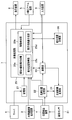
- FIG. 1 is a diagram illustrating a configuration of a main part of the medical observation system according to the embodiment.
- the medical observation system 1 includes an endoscope 2, an endoscope image generation device 3, a position detection device 4, an X-ray C arm device 5, a server 6, and an image processing device. 7, a display device 8, and an input device 9.
- the endoscope 2 can be inserted into a subject and has an elongated insertion portion 11 that is formed with flexibility, an operation portion 12 that is connected to a proximal end portion of the insertion portion 11, and an operation. And a cable 13 extending from the side surface of the portion 12.
- the endoscope 2 is configured to be connected to the endoscope image generating device 3 via the cable 13 and to be connected to the position detecting device 4 via the cable 14.
- An imaging unit 10 for imaging a subject in the subject is provided at the distal end 11A of the insertion unit 11.
- the imaging unit 10 is configured to image a subject using an imaging element such as a CCD and generate an imaging signal corresponding to the captured subject. Then, the imaging signal generated in the imaging unit 10 is output to the endoscope image generating device 3 via the operation unit 12 and the cable 13.
- a plurality of magnetic sensors 51 that detect a magnetic field emitted from the position detection device 4 and generate an electric signal corresponding to the detected magnetic field are provided at a predetermined interval at a portion from the distal end portion 11A to the proximal end portion of the insertion portion 11. It is arranged for each.
- the electrical signals generated by the plurality of magnetic sensors 51 are output to the position detection device 4 via the operation unit 12 and the cable 14.
- the endoscope image generation device 3 is configured to be connected to the endoscope 2 via a cable 13.
- the endoscopic image generation device 3 generates endoscopic image data by performing predetermined image processing on an imaging signal output from the endoscope 2 via the cable 13, and generates the generated endoscopic image.
- the mirror image data is output to the image processing device 7.
- the position detection device 4 is configured to be connected to the endoscope 2 via the cable 14.
- the position detection device 4 extracts an electrical signal generated in the magnetic sensor 51 located on the most distal end side of the insertion portion 11 from the electrical signal input through the cable 14 and converts the electrical signal into the extracted electrical signal.
- the tip position data and the tip direction data indicating the calculation result obtained by the calculation are obtained.
- the generated tip position data and tip direction data are sequentially output to the image processing device 7.
- the position detection device 4 performs an operation for detecting the insertion shape of the insertion portion 11 based on an electrical signal input through the cable 14, and generates insertion shape data indicating the operation result obtained by the operation,
- the generated insertion shape data is configured to be output to the image processing device 7.
- the position detection device 4 performs an operation for detecting the position of an X-ray C-arm (described later) in the X-ray C-arm device 5 based on an electric signal input through the cable 15 and obtained by the operation.
- X-ray imaging position data indicating the calculation result is generated, and the generated X-ray imaging position data is output to the image processing device 7.
- the X-ray C-arm device 5 is provided with an X-ray generation unit that emits X-rays that pass through a subject and an X-ray detection unit that detects X-rays emitted from the X-ray generation unit at positions substantially opposite to each other. And an X-ray C-arm. Further, the X-ray C-arm device 5 obtains intraoperative X-ray image data from multiple directions by rotating the X-ray C-arm to an arbitrary angle, and the obtained intraoperative X-ray image data is converted into an image processing device. 7 is configured to output to 7.
- the X-ray C-arm of the X-ray C-arm device 5 is provided with a magnetic sensor (not shown) that detects a magnetic field emitted from the position detection device 4 and generates an electrical signal corresponding to the detected magnetic field.
- the electrical signal generated by the magnetic sensor is output to the position detection device 4 via the cable 15.
- the server 6 stores preoperative multi-slice image data 16a to 16n acquired by imaging a subject by CT or MRI, for example.
- the preoperative multi-slice image data 16a to 16n are output to the image processing apparatus 7 via a network line such as a local area network.
- the pre-operative multi-slice image data 16a to 16n are not limited to being configured to be output from the server 6 to the image processing device 7, but may be, for example, a portable storage medium such as a CD-ROM.
- the preoperative multi-slice image data 16a to 16n stored in advance may be read by the image processing device 7.
- the display device 8 includes, for example, a liquid crystal display and is configured to display an image output from the image processing device 7.
- the input device 9 includes, for example, a touch panel or a keyboard, and is configured to be able to input information to the image processing device 7 in accordance with a user operation such as a surgeon. According to the present embodiment, for example, the same information as that of the input device 9 may be input through a scope switch (not shown) of the operation unit 12 of the endoscope 2.
- the image processing device 7 includes a storage unit 21, a tip position storage unit 22, a calculation unit 23, a tip coordinate conversion unit 24, an image processing unit 25, a calculus position storage unit 26, It is comprised.
- FIG. 2 is a diagram for explaining an example of the configuration of the image processing apparatus according to the embodiment.
- the storage unit 21 includes, for example, a storage device such as a hard disk drive, and is configured to store preoperative multi-slice image data 16a to 16n output from the server 6.
- the tip position storage unit 22 is configured to store insertion shape data output from the position detection device 4.
- the tip position storage unit 22 is configured to store the tip position data and tip direction data output from the position detection device 4 with a time stamp TSP.
- a time stamp TSP According to such a configuration of the tip position storage unit 22, for example, as shown in FIG. 3, the X coordinate value A1, the Y coordinate value B1, and the Z coordinate value of the tip position data output from the position detection device 4 are used. C1 is stored with a time stamp TSP1. In FIG. 3, the tip direction data is omitted for simplicity.
- FIG. 3 is a diagram illustrating an example of tip position data stored in the tip position storage unit.
- the calculation unit 23 detects that input of information for performing alignment is performed in the input device 9, the coordinate value of the tip position data stored in the tip position storage unit 22 and image processing are performed.
- the tip coordinate conversion unit 24 converts the tip position data and the tip direction data stored in the tip position storage unit 22 into coordinate values indicating positions on the three-dimensional data based on the conversion formula calculated by the calculation unit 23. It is configured as follows. Further, the tip coordinate conversion unit 24 stores the tip position data and tip direction data after conversion, the tip position data and direction data before conversion, and the time stamp TSP in the tip position storage unit 22 together. It is configured. According to such processing of the tip coordinate conversion unit 24, for example, as shown in FIG.
- the X coordinate value A1, the Y coordinate value B1, and the Z coordinate value in the real space which are tip position data before conversion, C1, the X coordinate value D1, the Y coordinate value E1, the Z coordinate value F1, and the time stamp TSP1 on the three-dimensional data that is the tip position data after conversion, and the time stamp TSP1 are stored together in the tip position storage unit 22. Further, according to the processing of the tip coordinate conversion unit 24 as described above, the tip position data on the three-dimensional data is stored in the tip position storage unit 22 in time series.
- the coordinate position of the tip of can be adjusted.
- the image processing unit 25 generates three-dimensional model data of the subject using the preoperative multi-slice image data 16a to 16n stored in the storage unit 21, and from the generated three-dimensional model data of the subject, It is configured to extract three-dimensional model data 31 (see FIG. 4) of a predetermined luminal organ including the ureter 40, renal pelvis 41, kidney cups 42 to 49, and stone ST.
- the image processing unit 25 is configured to extract the coordinate value of the core line data of the lumen in the three-dimensional model data 31 and output the coordinate value of the extracted core line data to the calculation unit 23. Further, the image processing unit 25 rotates the three-dimensional model data 31 extracted as described above by an arbitrary angle so that a predetermined luminal organ can be observed from two directions. (See FIG. 5).
- FIG. 4 is a schematic diagram for explaining an example of three-dimensional model data of a predetermined luminal organ.
- FIG. 5 is a schematic diagram for explaining an example different from FIG. 4 of the three-dimensional model data of a predetermined luminal
- the image processing unit 25 of the present embodiment includes not only the ureter 40, the renal pelvis 41, and the kidney cups 42 to 49, but also, for example, a three-dimensional model including the bladder and urethra from the three-dimensional model data of the subject. Data may be extracted.
- the image processing unit 25 according to the present embodiment is not limited to extracting the three-dimensional model data of a predetermined luminal organ from the three-dimensional model data of the subject.
- the stored three-dimensional model data of the predetermined luminal organ may be read.
- the image processing unit 25 includes a pseudo X-ray image generation unit 25a, a movement detection unit 25b, a calculus position acquisition unit 25c, and a display image generation unit 25d.
- the pseudo X-ray image generation unit 25a is configured to generate pseudo X-ray image data based on the preoperative multi-slice image data 16a to 16n stored in the storage unit 21.
- the movement detection unit 25b calculates a difference value by performing a matching process on the endoscope image data at the initial position of the calculus ST and the endoscope image data at the current position of the calculus ST, and calculates the difference value.
- the difference value is acquired as the movement amount of the calculus ST.
- the movement detection unit 25b is obtained by imaging the pseudo X-ray image data including the calculus ST generated by the pseudo X-ray image generation unit 25a and the calculus ST present in the subject by the X-ray C arm device 5.
- a difference value is calculated by performing a matching process on the obtained X-ray image data, and the calculated difference value is acquired as a movement amount of the calculus ST.
- the endoscopic image data at the initial position of the calculus ST is, for example, as moving image data or still image data obtained by imaging the calculus ST before the treatment for the calculus ST present in the subject is performed. It is assumed that the image is output from the endoscopic image generation device 3 and stored in a memory (not shown) of the image processing unit 25.
- the endoscope image data at the current position of the calculus ST is, for example, moving image data or a still image obtained by imaging the calculus ST while a treatment for the calculus ST present in the subject is being performed. It is assumed that the data is output from the endoscope image generation device 3 as data and stored in a memory (not shown) of the image processing unit 25.
- the movement detection unit 25b is based on the comparison result obtained by comparing the movement amount of the calculus ST acquired as described above with a predetermined threshold TH, or information corresponding to the operation of the switch SW1 (not shown) of the input device 9. Based on the determination result which determined whether the input was made, it is comprised so that it may detect whether the calculus ST moved.
- the switch SW1 moves the calculus ST when it is clear that the calculus ST has been moved in accordance with the user's intention, such as when the calculus ST is moved to a position suitable for treatment. It is configured as a switch that can input information for notifying the image processing unit 25 of information.
- the calculus position acquisition unit 25c is a coordinate value indicating the initial position of the calculus ST in the three-dimensional model data of the subject based on the three-dimensional model data of the subject generated using the preoperative multi-slice image data 16a to 16n. Is configured to get.
- the calculus position acquisition unit 25c includes the conversion formula calculated by the calculation unit 23 and the X-ray imaging position data output from the position detection device 4 when movement of the calculus ST is detected by the movement detection unit 25b. Based on the movement amount acquired by the movement detection unit 25b, the coordinates indicating the current position of the calculus ST on the three-dimensional data are projected onto the pseudo X-ray image data generated by the pseudo X-ray image generation unit 25a. Configured to retrieve values.
- the calculus position acquisition unit 25c when the movement of the calculus ST is detected by the movement detection unit 25b, the X coordinate value Dn, the Y coordinate value En, and the Z coordinate of the latest tip position data to which the time stamp TSPn is given.
- the value Fn (see FIG. 3) is read from the tip position storage unit 22, and the read X coordinate value Dn, Y coordinate value En, and Z coordinate value Fn are acquired as coordinate values indicating the current position of the calculus ST on the three-dimensional data. Is configured to do.
- the calculus position acquisition unit 25c sequentially uses the coordinate value indicating the initial position of the calculus ST on the three-dimensional data and the coordinate value indicating the current position of the calculus ST on the three-dimensional data as calculus position data to the calculus position storage unit 26 sequentially. It is configured to output.
- the display image generation unit 25d generates one or more markers M indicating the position of the calculus ST on the three-dimensional data based on the calculus position data stored in the calculus position storage unit 26, and the generated marker M Is synthesized with the three-dimensional model data 31 and 32.
- the display image generating unit 25d generates the three-dimensional model data 31 and 32 including the marker M and the endoscope image data output from the endoscope image generating device 3 by performing predetermined image processing.
- a display image is synthesized by combining the endoscopic image 34 and one preoperative multislice image data 16i selected by the user from the preoperative multislice image data 16a to 16n stored in the storage unit 21.
- the generated display image is output to the display device 8. Then, for example, an image as shown in FIG. 6 is displayed on the display device 8 by the processing of the display image generation unit 25d.
- FIG. 6 is a diagram for explaining an example of an image displayed on the display device.
- the display image generation unit 25d When the display image generation unit 25d detects that information according to the operation of the switch SW2 (not shown) of the input device 9 is input, the display image generation unit 25d stores the calculus position data stored in the calculus position storage unit 26. Based on this, the display mode of the marker indicating the position of the calculus ST on the three-dimensional data is changed.
- the switch SW2 is used to input information for selecting one or more markers displayed in the three-dimensional model data 31 and 32 and to display the selected one or more markers.
- the switch is configured as a switch that can input information for changing to a display mode to the image processing unit 25.
- the calculus position storage unit 26 is configured to store the calculus position data sequentially output from the image processing unit 25 with a time stamp TSQ.
- the time stamp TSQ1 is added to the X coordinate value G1, the Y coordinate value H1, and the Z coordinate value I1 indicating the initial position of the calculus ST. Is stored in a state of being assigned.
- the time is set to the X coordinate value Gm, the Y coordinate value Hm, and the Z coordinate value Im indicating the latest position of the calculus ST.
- calculus position data sequentially output from the image processing unit 25 is stored in time series.
- FIG. 7 is a diagram illustrating an example of calculus position data stored in the calculus position storage unit.
- FIG. 8 is a flowchart for explaining an example of processing performed in the medical observation system according to the embodiment.
- the image processing unit 25 generates three-dimensional model data of the subject using the preoperative multi-slice image data 16a to 16n stored in the storage unit 21, and from the generated three-dimensional model data of the subject, Three-dimensional model data 31 of a predetermined luminal organ including the ureter 40, renal pelvis 41, renal cup 42 to 49, and calculus ST is extracted. Further, the image processing unit 25 generates three-dimensional model data 32 obtained by rotating the three-dimensional model data 31 extracted as described above by an arbitrary angle.
- the calculus position acquisition unit 25c is a coordinate value indicating the initial position of the calculus ST in the three-dimensional model data of the subject based on the three-dimensional model data of the subject generated using the preoperative multi-slice image data 16a to 16n. And the acquired coordinate value is output to the calculus position storage unit 26 as calculus position data.
- the display image generation unit 25d performs the following process as a process for generating an image indicating the initial position of the calculus (step S1 in FIG. 8).
- the display image generation unit 25d generates a marker M1 indicating the initial position of the calculus ST on the three-dimensional data based on the calculus position data stored in the calculus position storage unit 26, and the generated marker M1 is three-dimensionally generated.
- the model data 31 and 32 are combined.
- the display image generation unit 25d generates a display image by combining the three-dimensional model data 31 and 32 including the marker M1, the endoscopic image 34, and the preoperative multi-slice image data 16i.
- the generated display image is output to the display device 8.
- FIG. 9 is a diagram for explaining another example of an image displayed on the display device.
- FIG. 9 for the sake of simplicity, it is assumed that details of the endoscopic image 34 displayed on the display device 8 before the insertion unit 11 is inserted into the subject are omitted.
- the user inserts the insertion portion 11 into the subject while confirming the position of the marker M1 in the image displayed on the display device 8, so that the distal end portion 11 ⁇ / b> A of the insertion portion 11 is formed as a stone in the kidney cup 49. Arranged in the vicinity of ST. Then, according to such a user's insertion operation, for example, as shown in FIG. 10, an endoscopic image 34 including a calculus ST located in the kidney cup 49 is displayed on the display device 8.
- FIG. 10 is a diagram for explaining another example of an image displayed on the display device.
- the movement detection unit 25b performs any one of the processes described below as a process for detecting the movement of the calculus ST (step S2 in FIG. 8).
- the movement detection unit 25b calculates a difference value by performing a matching process on the endoscope image data at the initial position of the calculus ST and the endoscope image data at the current position of the calculus ST, and calculates the difference value.
- the difference value is acquired as the movement amount DA of the calculus ST.
- the movement detection unit 25b compares the movement amount DA with a predetermined threshold value TH1, and detects the movement of the calculus ST when the comparison result that the movement amount DA is equal to or greater than the predetermined threshold value TH1 is obtained.
- the movement detection unit 25b is obtained by imaging the pseudo X-ray image data including the calculus ST generated by the pseudo X-ray image generation unit 25a and the calculus ST present in the subject by the X-ray C arm device 5. A difference value is calculated by performing a matching process on the X-ray image data, and the calculated difference value is acquired as a movement amount DB of the calculus ST. Then, the movement detection unit 25b compares the movement amount DB with the predetermined threshold value TH2, and detects the movement of the calculus ST when the comparison result that the movement amount DB is equal to or greater than the predetermined threshold value TH2 is obtained.
- the movement detection unit 25b determines whether or not information is input according to the operation of the switch SW1 of the input device 9, and when the determination result that the information is input according to the operation of the switch SW1 is obtained. It detects that the calculus ST has moved.
- the calculus position acquisition unit 25c performs any one of the following processes as a process for acquiring the current position of the calculus ST. This is performed (step S3 in FIG. 8).
- the calculus position acquisition unit 25c includes the conversion formula calculated by the calculation unit 23 and the X-ray imaging position data output from the position detection device 4 when movement of the calculus ST is detected by the movement detection unit 25b. Based on the movement amount DA or DB acquired by the movement detection unit 25b on the pseudo X-ray image data generated by the pseudo X-ray image generation unit 25a, the current position of the stone ST on the three-dimensional data Get the coordinate value indicating. And the calculus position acquisition part 25c outputs the coordinate value which shows the present position of the calculus ST on three-dimensional data to the calculus position storage part 26 as calculus position data.
- the calculus position acquisition unit 25c when the movement of the calculus ST is detected by the movement detection unit 25b, the X coordinate value Dn, the Y coordinate value En, and the Z coordinate value Fn of the latest tip position data to which the time stamp TSPn is given. Is read from the tip position storage unit 22, and the read X coordinate value Dn, Y coordinate value En, and Z coordinate value Fn are acquired as coordinate values indicating the current position of the calculus ST on the three-dimensional data. And the calculus position acquisition part 25c outputs the coordinate value which shows the present position of the calculus ST on three-dimensional data to the calculus position storage part 26 as calculus position data.
- the display image generation unit 25d having a function as a position information presentation unit performs the following process as a process for generating an image indicating the current position of the calculus (step S4 in FIG. 8).
- the display image generation unit 25d generates a marker Mn indicating the current position of the calculus ST on the three-dimensional data based on the latest calculus position data stored in the calculus position storage unit 26, and the generated marker Mn While combining with the three-dimensional model data 31 and 32, the marker generated before the generated marker Mn is deleted from the three-dimensional model data 31 and 32.
- the display image generation unit 25d generates a display image by combining the three-dimensional model data 31 and 32 including the marker Mn, the endoscopic image 34, and the preoperative multi-slice image data 16i. The generated display image is output to the display device 8.
- FIG. 11 is a diagram for explaining another example of an image displayed on the display device.
- the display image generation unit 25d is not limited to the one that generates a display image by combining the marker indicating the position of the calculus ST with the three-dimensional model data 31 of a predetermined luminal organ, for example.
- the three-dimensional model data 31 of the predetermined luminal organ may be combined with the three-dimensional model data of the subject before extraction to generate a display image, or a pseudo X-ray image generation unit
- the display image may be generated by combining with the pseudo X-ray image data generated by 25a.
- the display image generation unit 25d is not limited to performing the above-described processing in step S4 in FIG. 8, and for example, inputs information according to the operation of the switch SW2 of the input device 9.
- a plurality of markers including at least the marker Mn may be colored with mutually different colors, and the plurality of colored markers may be combined with the three-dimensional model data 31 and 32.
- the display image generation unit 25d displays, for example, a marker that indicates the position of the calculus ST and a comment that is given to the marker according to the operation of the input device 9 together. It is also possible to generate an image for use.
- the display image generation unit 25d is not limited to performing the above-described processing in step S4 in FIG. 8, and for example, inputs information according to the operation of the switch SW2 of the input device 9.
- a marker Mn indicating the current position of the calculus ST on the three-dimensional data
- a line segment LS indicating the movement trajectory of the calculus ST on the three-dimensional data from the markers M1 to Mn are respectively generated.
- the generated marker Mn and line segment LS may be combined with the three-dimensional model data 31 and 32.
- FIG. 12 is a diagram for explaining another example of an image displayed on the display device.
Landscapes
- Health & Medical Sciences (AREA)
- Life Sciences & Earth Sciences (AREA)
- Engineering & Computer Science (AREA)
- Medical Informatics (AREA)
- Surgery (AREA)
- Physics & Mathematics (AREA)
- Heart & Thoracic Surgery (AREA)
- Public Health (AREA)
- Biomedical Technology (AREA)
- General Health & Medical Sciences (AREA)
- Veterinary Medicine (AREA)
- Molecular Biology (AREA)
- Animal Behavior & Ethology (AREA)
- Pathology (AREA)
- Biophysics (AREA)
- Nuclear Medicine, Radiotherapy & Molecular Imaging (AREA)
- Radiology & Medical Imaging (AREA)
- Optics & Photonics (AREA)
- High Energy & Nuclear Physics (AREA)
- Computer Vision & Pattern Recognition (AREA)
- Theoretical Computer Science (AREA)
- General Physics & Mathematics (AREA)
- Signal Processing (AREA)
- Human Computer Interaction (AREA)
- Software Systems (AREA)
- Computer Graphics (AREA)
- Computer Hardware Design (AREA)
- General Engineering & Computer Science (AREA)
- Physiology (AREA)
- Psychiatry (AREA)
- Artificial Intelligence (AREA)
- Robotics (AREA)
- Multimedia (AREA)
- Architecture (AREA)
- Endoscopes (AREA)
- Apparatus For Radiation Diagnosis (AREA)
- Instruments For Viewing The Inside Of Hollow Bodies (AREA)
Abstract
医療用観察システムは、被検体の複数の断層画像を用いて生成された3次元画像上の所定の対象物の初期位置を示す情報である第1の位置情報を取得する第1の位置情報取得部と、被検体内に存在する所定の対象物を撮像した画像に基づき、所定の対象物の移動を検知する移動検知部と、所定の対象物の移動が検知された際に、3次元画像上の所定の対象物の現在位置を示す情報である第2の位置情報を取得する第2の位置情報取得部と、第1の位置情報及び第2の位置情報を時系列に格納する位置情報記憶部と、位置情報記憶部に格納されている各位置情報のうちの少なくとも最新の位置情報を3次元画像上または複数の断層画像に基づいて生成された擬似透視画像上のいずれかに示す位置情報提示部と、を有する。
Description
本発明は、医療用観察システムに関し、特に、生体内に存在する所定の対象物の位置を特定するために用いられる医療用観察システムに関するものである。
腎臓内の結石を除去するための処置方法として、例えば、ESWL(体外衝撃波砕石術)、TUL(経尿道的尿管砕石術)、及び、f-TUL(経尿道的結石砕石術)等の処置方法が従来知られている。
また、例えば、日本国特表2013-527782号公報には、腎臓内の結石の除去を促進するための処置方法として、蛍光透視法等の既知の造影モダリティを用いて当該結石の位置を特定し、当該結石に対して所定の範囲の圧力振幅を有する押出超音波を当てる方法が開示されている。
ところで、TULまたはf-TULにおいては、破砕前後における結石の現在位置を、内視鏡画像を確認しながら当該結石の除去に係る処置を行う術者の主観的判断に基づいて特定せざるを得ないため、当該術者に過度な負担を強いてしまう場合がある、という課題が生じている。
また、日本国特表2013-527782号公報に開示された構成によれば、蛍光透視法等の既知の造影モダリティを用いて結石を可視化した際に、当該結石の現在位置を視覚的に特定し辛い画像が生成される場合があり、すなわち、当該結石の除去に係る処置を行う術者に過度な負担を強いてしまう場合がある、という課題が生じている。
本発明は、前述した事情に鑑みてなされたものであり、結石の除去に係る処置を行う術者の負担を軽減することが可能な医療用観察システムを提供することを目的としている。
本発明の一態様の医療用観察システムは、被検体の複数の断層画像を用いて生成された3次元画像に基づき、前記3次元画像上の所定の対象物の初期位置を示す情報である第1の位置情報を取得するための処理を行うように構成された第1の位置情報取得部と、前記被検体内に存在する前記所定の対象物を撮像した画像に基づき、前記所定の対象物の移動を検知するように構成された移動検知部と、前記所定の対象物の移動が前記移動検知部により検知された際に、前記3次元画像上の前記所定の対象物の現在位置を示す情報である第2の位置情報を取得するための処理を行うように構成された第2の位置情報取得部と、前記第1の位置情報取得部により取得された前記第1の位置情報、及び、前記第2の位置情報取得部により取得された前記第2の位置情報を時系列に格納するように構成された位置情報記憶部と、前記位置情報記憶部に格納されている各位置情報のうちの少なくとも最新の位置情報を、前記3次元画像上、または、前記複数の断層画像に基づいて生成された擬似透視画像上のいずれかに示すための処理を行うように構成された位置情報提示部と、を有する。
以下、本発明の実施の形態について、図面を参照しつつ説明を行う。
図1から図12は、本発明の実施例に係るものである。図1は、実施例に係る医療用観察システムの要部の構成を示す図である。
医療用観察システム1は、図1に示すように、内視鏡2と、内視鏡画像生成装置3と、位置検出装置4と、X線Cアーム装置5と、サーバ6と、画像処理装置7と、表示装置8と、入力装置9と、を有して構成されている。
内視鏡2は、被検体内に挿入可能であるとともに可撓性を有して形成された細長の挿入部11と、挿入部11の基端部に連設された操作部12と、操作部12の側面より延設されたケーブル13と、を有して構成されている。
内視鏡2は、ケーブル13を介して内視鏡画像生成装置3に接続されるとともに、ケーブル14を介して位置検出装置4に接続されるように構成されている。
挿入部11の先端部11Aには、被検体内の被写体を撮像するための撮像部10が設けられている。
撮像部10は、例えば、CCD等の撮像素子により被写体を撮像し、当該撮像した被写体に応じた撮像信号を生成するように構成されている。そして、撮像部10において生成された撮像信号は、操作部12及びケーブル13を経て内視鏡画像生成装置3へ出力される。
挿入部11の先端部11Aから基端部にかけての部分には、位置検出装置4から発せられる磁界を検出し、当該検出した磁界に応じた電気信号を生成する複数の磁気センサ51が所定の間隔毎に配設されている。そして、複数の磁気センサ51において生成された電気信号は、操作部12及びケーブル14を経て位置検出装置4へ出力される。
内視鏡画像生成装置3は、ケーブル13を介して内視鏡2に接続されるように構成されている。また、内視鏡画像生成装置3は、内視鏡2からケーブル13を経て出力される撮像信号に対して所定の画像処理を施すことにより内視鏡画像データを生成し、当該生成した内視鏡画像データを画像処理装置7へ出力するように構成されている。
位置検出装置4は、ケーブル14を介して内視鏡2に接続されるように構成されている。また、位置検出装置4は、ケーブル14を経て入力される電気信号の中から、挿入部11の最も先端側に位置する磁気センサ51において生成された電気信号を抽出し、当該抽出した電気信号に基づいて挿入部11の先端部11Aの実空間上の位置及び方向を検出するための演算を所定の時間間隔毎に行い、当該演算により得られた演算結果を示す先端位置データ及び先端方向データを生成し、当該生成した先端位置データ及び先端方向データを画像処理装置7へ順次出力するように構成されている。
位置検出装置4は、ケーブル14を経て入力される電気信号に基づき、挿入部11の挿入形状を検出するための演算を行い、当該演算により得られた演算結果を示す挿入形状データを生成し、当該生成した挿入形状データを画像処理装置7へ出力するように構成されている。
位置検出装置4は、ケーブル15を経て入力される電気信号に基づき、X線Cアーム装置5におけるX線Cアーム(後述)の位置等を検出するための演算を行い、当該演算により得られた演算結果を示すX線撮像位置データを生成し、当該生成したX線撮像位置データを画像処理装置7へ出力するように構成されている。
X線Cアーム装置5は、被検体を透過するX線を発するX線発生部と、当該X線発生部から発せられたX線を検出するためのX線検出部を略対向する位置に設けたX線Cアームと、を具備して構成されている。また、X線Cアーム装置5は、X線Cアームを任意の角度に回転させることにより、多方向から術中のX線画像データを取得し、当該取得した術中のX線画像データを画像処理装置7へ出力するように構成されている。
X線Cアーム装置5のX線Cアームには、位置検出装置4から発せられる磁界を検出し、当該検出した磁界に応じた電気信号を生成する磁気センサ(不図示)が設けられている。そして、前述の磁気センサにおいて生成された電気信号は、ケーブル15を経て位置検出装置4へ出力される。
サーバ6には、例えば、CTまたはMRI等により被検体を撮像して取得した術前マルチスライス画像データ16a~16nが格納されている。術前マルチスライス画像データ16a~16nは、例えば、ローカルエリアネットワーク等のネットワーク回線を経て画像処理装置7へ出力される。
なお、本実施例においては、術前マルチスライス画像データ16a~16nがサーバ6から画像処理装置7へ出力されるように構成したものに限らず、例えば、CD-ROM等の可搬型記憶媒体に予め格納された術前マルチスライス画像データ16a~16nが画像処理装置7により読み込まれるようにしてもよい。
表示装置8は、例えば、液晶ディスプレイ等を具備し、画像処理装置7から出力される画像を表示するように構成されている。
入力装置9は、例えば、タッチパネルまたはキーボード等を具備し、術者等のユーザの操作に応じた情報の入力を画像処理装置7に対して行うことができるように構成されている。なお、本実施例によれば、例えば、内視鏡2の操作部12のスコープスイッチ(不図示)等において、入力装置9と同様の情報を入力することができるようにしてもよい。
次に、画像処理装置7の詳細な構成等について説明する。
画像処理装置7は、図2に示すように、記憶部21と、先端位置記憶部22と、演算部23と、先端座標変換部24と、画像処理部25と、結石位置記憶部26と、を有して構成されている。図2は、実施例に係る画像処理装置の構成の一例を説明するための図である。
記憶部21は、例えば、ハードディスクドライブ等の記憶装置を具備し、サーバ6から出力される術前マルチスライス画像データ16a~16nを格納するように構成されている。
先端位置記憶部22は、位置検出装置4から出力される挿入形状データを格納するように構成されている。
先端位置記憶部22は、位置検出装置4から出力される先端位置データ及び先端方向データにタイムスタンプTSPを付与して格納するように構成されている。そして、このような先端位置記憶部22の構成によれば、例えば、図3に示すように、位置検出装置4から出力される先端位置データのX座標値A1、Y座標値B1及びZ座標値C1にタイムスタンプTSP1が付与された状態で格納される。なお、図3においては、簡単のため、先端方向データを省略して示している。図3は、先端位置記憶部に格納される先端位置データの一例を示す図である。
演算部23は、位置合わせを実施するための情報の入力が入力装置9において行われたことを検知した際に、先端位置記憶部22に格納されている先端位置データの座標値と、画像処理部25から出力される芯線データの座標値(後述)と、を比較することにより、実空間上の位置を示す座標値を3次元データ上の位置を示す座標値に変換するための変換式を算出するように構成されている。
先端座標変換部24は、演算部23で算出された変換式に基づき、先端位置記憶部22に格納されている先端位置データ及び先端方向データを3次元データ上の位置を示す座標値に変換するように構成されている。また、先端座標変換部24は、変換後の先端位置データ及び先端方向データと、変換前の先端位置データ及び方向データと、タイムスタンプTSPと、を併せて先端位置記憶部22に格納するように構成されている。そして、このような先端座標変換部24の処理によれば、例えば、図3に示すように、変換前の先端位置データである実空間上のX座標値A1、Y座標値B1及びZ座標値C1と、変換後の先端位置データである3次元データ上のX座標値D1、Y座標値E1及びZ座標値F1と、タイムスタンプTSP1と、が併せて先端位置記憶部22に格納される。また、前述のような先端座標変換部24の処理によれば、3次元データ上の先端位置データが先端位置記憶部22に時系列に格納される。
すなわち、以上に述べたような演算部23及び先端座標変換部24の処理によれば、所定の管腔臓器の3次元モデルデータ上の座標位置と、位置検出装置4において取得された挿入部11の先端の座標位置と、を合わせ込むことができる。
画像処理部25は、記憶部21に格納された術前マルチスライス画像データ16a~16nを用いて被検体の3次元モデルデータを生成し、当該生成した被検体の3次元モデルデータの中から、尿管40、腎盂41、腎杯42~49及び結石STを含む所定の管腔臓器の3次元モデルデータ31(図4参照)を抽出するように構成されている。また、画像処理部25は、3次元モデルデータ31における管腔の芯線データの座標値を抽出し、当該抽出した芯線データの座標値を演算部23へ出力するように構成されている。また、画像処理部25は、所定の管腔臓器を2方向から観察できるようにするために、前述のように抽出した3次元モデルデータ31を任意の角度だけ回転させた3次元モデルデータ32(図5参照)を生成するように構成されている。図4は、所定の管腔臓器の3次元モデルデータの一例を説明するための模式図である。図5は、所定の管腔臓器の3次元モデルデータの、図4とは異なる例を説明するための模式図である。
なお、本実施例の画像処理部25は、被検体の3次元モデルデータの中から、尿管40、腎盂41及び腎杯42~49のみならず、例えば、膀胱や尿道を含めた3次元モデルデータを抽出するようにしてもよい。また、本実施例の画像処理部25は、被検体の3次元モデルデータの中から所定の管腔臓器の3次元モデルデータを抽出するものに限らず、例えば、サーバ6または記憶部21に予め格納されている当該所定の管腔臓器の3次元モデルデータを読み込むものであってもよい。
一方、画像処理部25は、擬似X線画像生成部25aと、移動検知部25bと、結石位置取得部25cと、表示用画像生成部25dと、を有して構成されている。
擬似X線画像生成部25aは、記憶部21に格納された術前マルチスライス画像データ16a~16nに基づいて擬似X線画像データを生成するように構成されている。
移動検知部25bは、結石STの初期位置の内視鏡画像データと、結石STの現在位置の内視鏡画像データと、に対してマッチング処理を施すことにより差分値を算出し、当該算出した差分値を結石STの移動量として取得するように構成されている。または、移動検知部25bは、擬似X線画像生成部25aにより生成された結石STを含む擬似X線画像データと、X線Cアーム装置5により被検体内に存在する結石STを撮像して得られたX線画像データと、に対してマッチング処理を施すことにより差分値を算出し、当該算出した差分値を結石STの移動量として取得するように構成されている。
なお、結石STの初期位置の内視鏡画像データは、例えば、被検体内に存在する結石STに対する処置が行われる前に当該結石STを撮像して得られた動画データまたは静止画データとして内視鏡画像生成装置3から出力され、画像処理部25の図示しないメモリ等に格納されるものとする。また、結石STの現在位置の内視鏡画像データは、例えば、被検体内に存在する結石STに対する処置が行われている最中に当該結石STを撮像して得られた動画データまたは静止画データとして内視鏡画像生成装置3から出力され、画像処理部25の図示しないメモリ等に格納されるものとする。
移動検知部25bは、前述のように取得した結石STの移動量と所定の閾値THとを比較した比較結果に基づき、または、入力装置9のスイッチSW1(不図示)の操作に応じた情報の入力がなされたか否かを判定した判定結果に基づき、結石STが移動したか否かを検知するように構成されている。なお、スイッチSW1は、例えば、処置に適した位置に結石STを移動させた場合等のような、ユーザの意図に応じて結石STを移動させたことが明白である場合において、結石STが移動したことを告知するための情報の入力を画像処理部25に対して行うことが可能なスイッチとして構成されている。
結石位置取得部25cは、術前マルチスライス画像データ16a~16nを用いて生成された被検体の3次元モデルデータに基づき、当該被検体の3次元モデルデータにおける結石STの初期位置を示す座標値を取得するように構成されている。
結石位置取得部25cは、結石STの移動が移動検知部25bにより検知された際に、演算部23により算出された変換式と、位置検出装置4から出力されるX線撮像位置データと、に基づき、移動検知部25bにより取得された移動量を、擬似X線画像生成部25aにより生成された擬似X線画像データ上に投影することにより、3次元データ上の結石STの現在位置を示す座標値を取得するように構成されている。
または、結石位置取得部25cは、結石STの移動が移動検知部25bにより検知された際に、タイムスタンプTSPnが付与された最新の先端位置データのX座標値Dn、Y座標値En及びZ座標値Fn(図3参照)を先端位置記憶部22から読み込み、当該読み込んだX座標値Dn、Y座標値En及びZ座標値Fnを3次元データ上の結石STの現在位置を示す座標値として取得するように構成されている。
結石位置取得部25cは、3次元データ上の結石STの初期位置を示す座標値、及び、3次元データ上の結石STの現在位置を示す座標値を結石位置データとして結石位置記憶部26へ順次出力するように構成されている。
表示用画像生成部25dは、結石位置記憶部26に格納されている結石位置データに基づき、3次元データ上の結石STの位置を示す1つ以上のマーカーMを生成し、当該生成したマーカーMを3次元モデルデータ31及び32に合成するように構成されている。
表示用画像生成部25dは、マーカーMを含む3次元モデルデータ31及び32と、内視鏡画像生成装置3から出力される内視鏡画像データに対して所定の画像処理を施すことにより生成した内視鏡画像34と、記憶部21に格納された術前マルチスライス画像データ16a~16nの中からユーザにより選択された1つの術前マルチスライス画像データ16iと、を合成することにより表示用画像を生成し、当該生成した表示用画像を表示装置8へ出力するように構成されている。そして、このような表示用画像生成部25dの処理により、例えば、図6に示すような画像が表示装置8に表示される。図6は、表示装置に表示される画像の一例を説明するための図である。
表示用画像生成部25dは、入力装置9のスイッチSW2(不図示)の操作に応じた情報の入力がなされたことを検知した際に、結石位置記憶部26に格納されている結石位置データに基づき、3次元データ上の結石STの位置を示すマーカーの表示態様を変更するように構成されている。なお、スイッチSW2は、例えば、3次元モデルデータ31及び32に表示されている1つ以上のマーカーを選択するための情報の入力、及び、当該選択した1つ以上のマーカーの表示態様を所望の表示態様に変更するための情報の入力を画像処理部25に対して行うことが可能なスイッチとして構成されている。
結石位置記憶部26は、画像処理部25から順次出力される結石位置データにタイムスタンプTSQを付与して格納するように構成されている。そして、このような結石位置記憶部26の構成によれば、例えば、図7に示すように、結石STの初期位置を示すX座標値G1、Y座標値H1及びZ座標値I1にタイムスタンプTSQ1が付与された状態で格納される。また、前述のような結石位置記憶部26の構成によれば、例えば、図7に示すように、結石STの最新の位置を示すX座標値Gm、Y座標値Hm及びZ座標値ImにタイムスタンプTSQmが付与された状態で格納される。すなわち、前述のような結石位置記憶部26の構成によれば、画像処理部25から順次出力される結石位置データが時系列に格納される。図7は、結石位置記憶部に格納される結石位置データの一例を示す図である。
続いて、本実施例の作用について説明する。図8は、実施例に係る医療用観察システムにおいて行われる処理の一例を説明するためのフローチャートである。
画像処理部25は、記憶部21に格納された術前マルチスライス画像データ16a~16nを用いて被検体の3次元モデルデータを生成し、当該生成した被検体の3次元モデルデータの中から、尿管40、腎盂41、腎杯42~49及び結石STを含む所定の管腔臓器の3次元モデルデータ31を抽出する。また、画像処理部25は、前述のように抽出した3次元モデルデータ31を任意の角度だけ回転させた3次元モデルデータ32を生成する。
結石位置取得部25cは、術前マルチスライス画像データ16a~16nを用いて生成された被検体の3次元モデルデータに基づき、当該被検体の3次元モデルデータにおける結石STの初期位置を示す座標値を取得し、当該取得した座標値を結石位置データとして結石位置記憶部26へ出力する。
表示用画像生成部25dは、結石の初期位置を示す画像を生成するための処理として、以下に述べるような処理を行う(図8のステップS1)。
表示用画像生成部25dは、結石位置記憶部26に格納されている結石位置データに基づき、3次元データ上の結石STの初期位置を示すマーカーM1を生成し、当該生成したマーカーM1を3次元モデルデータ31及び32に合成する。また、表示用画像生成部25dは、マーカーM1を含む3次元モデルデータ31及び32と、内視鏡画像34と、術前マルチスライス画像データ16iと、を合成して表示用画像を生成し、当該生成した表示用画像を表示装置8へ出力する。
そして、以上に述べたような処理が表示用画像生成部25dにおいて行われることにより、例えば、図9に示すような画像が表示装置8に表示される。図9は、表示装置に表示される画像の他の例を説明するための図である。なお、図9においては、簡単のため、挿入部11が被検体の内部に挿入される前に表示装置8に表示される内視鏡画像34の詳細を省略しているものとする。
ユーザは、表示装置8に表示される画像におけるマーカーM1の位置を確認しながら、挿入部11を被検体の内部へ挿入してゆくことにより、挿入部11の先端部11Aを腎杯49の結石STの近傍に配置する。そして、このようなユーザの挿入操作に応じ、例えば、図10に示すように、腎杯49内に位置する結石STを含む内視鏡画像34が表示装置8に表示される。図10は、表示装置に表示される画像の他の例を説明するための図である。
その後、ユーザは、表示装置8に表示される内視鏡画像34を確認しながら、腎杯49内に位置する結石STに対する処置を開始する。
移動検知部25bは、結石STの移動を検知するための処理として、以下に述べる各処理のうちのいずれか1つの処理を行う(図8のステップS2)。
移動検知部25bは、結石STの初期位置の内視鏡画像データと、結石STの現在位置の内視鏡画像データと、に対してマッチング処理を施すことにより差分値を算出し、当該算出した差分値を結石STの移動量DAとして取得する。そして、移動検知部25bは、移動量DAと所定の閾値TH1とを比較し、移動量DAが所定の閾値TH1以上であるとの比較結果を得た場合に結石STの移動を検知する。
移動検知部25bは、擬似X線画像生成部25aにより生成された結石STを含む擬似X線画像データと、X線Cアーム装置5により被検体内に存在する結石STを撮像して得られたX線画像データと、に対してマッチング処理を施すことにより差分値を算出し、当該算出した差分値を結石STの移動量DBとして取得する。そして、移動検知部25bは、移動量DBと所定の閾値TH2を比較し、移動量DBが所定の閾値TH2以上であるとの比較結果を得た場合に結石STの移動を検知する。
移動検知部25bは、入力装置9のスイッチSW1の操作に応じた情報の入力がなされたか否かを判定し、スイッチSW1の操作に応じた情報の入力がなされたとの判定結果を得た場合に結石STが移動したことを検知する。
結石位置取得部25cは、結石STの移動が移動検知部25bにより検知された際に、結石STの現在位置を取得するための処理として、以下に述べる各処理のうちのいずれか1つの処理を行う(図8のステップS3)。
結石位置取得部25cは、結石STの移動が移動検知部25bにより検知された際に、演算部23により算出された変換式と、位置検出装置4から出力されるX線撮像位置データと、に基づき、移動検知部25bにより取得された移動量DAまたはDBを、擬似X線画像生成部25aにより生成された擬似X線画像データ上に投影することにより、3次元データ上の結石STの現在位置を示す座標値を取得する。そして、結石位置取得部25cは、3次元データ上の結石STの現在位置を示す座標値を結石位置データとして結石位置記憶部26へ出力する。
結石位置取得部25cは、結石STの移動が移動検知部25bにより検知された際に、タイムスタンプTSPnが付与された最新の先端位置データのX座標値Dn、Y座標値En及びZ座標値Fnを先端位置記憶部22から読み込み、当該読み込んだX座標値Dn、Y座標値En及びZ座標値Fnを3次元データ上の結石STの現在位置を示す座標値として取得する。そして、結石位置取得部25cは、3次元データ上の結石STの現在位置を示す座標値を結石位置データとして結石位置記憶部26へ出力する。
位置情報提示部としての機能を備えた表示用画像生成部25dは、結石の現在位置を示す画像を生成するための処理として、以下に述べるような処理を行う(図8のステップS4)。
表示用画像生成部25dは、結石位置記憶部26に格納されている最新の結石位置データに基づき、3次元データ上の結石STの現在位置を示すマーカーMnを生成し、当該生成したマーカーMnを3次元モデルデータ31及び32に合成するとともに、当該生成したマーカーMnよりも前に生成したマーカーを3次元モデルデータ31及び32から消去する。また、表示用画像生成部25dは、マーカーMnを含む3次元モデルデータ31及び32と、内視鏡画像34と、術前マルチスライス画像データ16iと、を合成して表示用画像を生成し、当該生成した表示用画像を表示装置8へ出力する。
そして、以上に述べたような処理が表示用画像生成部25dにおいて行われることにより、例えば、図11に示すような画像が表示装置8に表示される。図11は、表示装置に表示される画像の他の例を説明するための図である。
すなわち、本実施例によれば、図8のステップS2~S4の処理を繰り返し行うことにより、結石STの現在位置を示すマーカーを、所定の管腔臓器の3次元モデルデータ上に略リアルタイムに表示させることができる。その結果、本実施例によれば、結石の除去に係る処置を行う術者の負担を軽減することができる。
なお、本実施例の表示用画像生成部25dは、結石STの位置を示すマーカーを、所定の管腔臓器の3次元モデルデータ31に合成して表示用画像を生成するものに限らず、例えば、当該所定の管腔臓器の3次元モデルデータ31を抽出する前の被検体の3次元モデルデータに合成して表示用画像を生成するものであってもよく、または、擬似X線画像生成部25aにより生成された擬似X線画像データに合成して表示用画像を生成するものであってもよい。
また、本実施例の表示用画像生成部25dは、図8のステップS4において、前述のような処理を行うものに限らず、例えば、入力装置9のスイッチSW2の操作に応じた情報の入力を検出した際に、少なくともマーカーMnを含む複数のマーカーを相互に異なる色で着色し、当該着色した複数のマーカーを3次元モデルデータ31及び32に合成するような処理を行ってもよい。
また、本実施例の表示用画像生成部25dは、例えば、結石STの位置を示すマーカーと、入力装置9の操作に応じて当該マーカーに付与されたコメントと、を併せて表示させるような表示用画像を生成するものであってもよい。
また、本実施例の表示用画像生成部25dは、図8のステップS4において、前述のような処理を行うものに限らず、例えば、入力装置9のスイッチSW2の操作に応じた情報の入力を検出した際に、3次元データ上の結石STの現在位置を示すマーカーMnと、マーカーM1からMnまでの3次元データ上の結石STの移動軌跡を示す線分LSと、をそれぞれ生成し、当該生成したマーカーMn及び線分LSを3次元モデルデータ31及び32に合成するようにしてもよい。そして、このような処理が表示用画像生成部25dにおいて行われた場合には、例えば、図12に示すような画像が表示装置8に表示される。図12は、表示装置に表示される画像の他の例を説明するための図である。
なお、本発明は、上述した各実施例に限定されるものではなく、発明の趣旨を逸脱しない範囲内において種々の変更や応用が可能であることは勿論である。
本出願は、2014年9月19日に日本国に出願された特願2014-191727号を優先権主張の基礎として出願するものであり、上記の開示内容は、本願明細書、請求の範囲、図面に引用されたものとする。
Claims (10)
- 被検体の複数の断層画像を用いて生成された3次元画像に基づき、前記3次元画像上の所定の対象物の初期位置を示す情報である第1の位置情報を取得するための処理を行うように構成された第1の位置情報取得部と、
前記被検体内に存在する前記所定の対象物を撮像した画像に基づき、前記所定の対象物の移動を検知するように構成された移動検知部と、
前記所定の対象物の移動が前記移動検知部により検知された際に、前記3次元画像上の前記所定の対象物の現在位置を示す情報である第2の位置情報を取得するための処理を行うように構成された第2の位置情報取得部と、
前記第1の位置情報取得部により取得された前記第1の位置情報、及び、前記第2の位置情報取得部により取得された前記第2の位置情報を時系列に格納するように構成された位置情報記憶部と、
前記位置情報記憶部に格納されている各位置情報のうちの少なくとも最新の位置情報を、前記3次元画像上、または、前記複数の断層画像に基づいて生成された擬似透視画像上のいずれかに示すための処理を行うように構成された位置情報提示部と、
を有することを特徴とする医療用観察システム。 - 前記移動検知部は、前記被検体内に挿入される内視鏡を用いて前記被検体内に存在する前記所定の対象物を撮像した内視鏡画像に基づいて前記所定の対象物の移動を検知する
ことを特徴とする請求項1に記載の医療用観察システム。 - 前記移動検知部は、前記所定の対象物を含む前記擬似透視画像と、前記被検体を透過する放射線を用いて前記被検体内に存在する前記所定の対象物を撮像した透視画像と、に基づいて前記所定の対象物の移動を検知する
ことを特徴とする請求項1に記載の医療用観察システム。 - 前記移動検知部は、前記内視鏡画像に基づいて前記所定の対象物の前記初期位置からの移動量を取得し、当該取得した移動量が所定の閾値以上である場合に前記所定の対象物の移動を検知する
ことを特徴とする請求項2に記載の医療用観察システム。 - 前記移動検知部は、前記擬似透視画像及び前記透視画像に基づいて前記所定の対象物の前記初期位置からの移動量を取得し、当該取得した移動量が所定の閾値以上である場合に前記所定の対象物の移動を検知する
ことを特徴とする請求項3に記載の医療用観察システム。 - 前記移動検知部は、前記内視鏡画像に基づいて前記所定の対象物の前記初期位置からの移動量を取得し、
前記第2の位置情報取得部は、前記所定の対象物の移動が前記移動検知部により検知された際に、前記移動検知部により取得された移動量を前記擬似透視画像上に投影することにより、前記第2の位置情報を取得する
ことを特徴とする請求項2に記載の医療用観察システム。 - 前記移動検知部は、前記透視画像に基づいて前記所定の対象物の前記初期位置からの移動量を取得し、
前記第2の位置情報取得部は、前記所定の対象物の移動が前記移動検知部により検知された際に、前記移動検知部により取得された移動量を前記擬似透視画像上に投影することにより、前記第2の位置情報を取得する
ことを特徴とする請求項3に記載の医療用観察システム。 - 前記第2の位置情報取得部は、前記移動検知部により取得された移動量を前記擬似透視画像上に投影することにより、前記第2の位置情報を取得する
ことを特徴とする請求項4に記載の医療用観察システム。 - 前記第2の位置情報取得部は、前記移動検知部により取得された移動量を前記擬似透視画像上に投影することにより、前記第2の位置情報を取得する
ことを特徴とする請求項5に記載の医療用観察システム。 - 前記被検体内に挿入される内視鏡の先端部の実空間上の位置を所定の時間間隔毎に検出するように構成された位置検出部と、
前記位置検出部により検出された前記先端部の実空間上の位置を、前記3次元画像上の位置を示す情報である先端位置情報に変換するための処理を行うように構成された位置情報変換部と、
前記先端位置情報を時系列に格納するように構成された先端位置情報記憶部と、をさらに有し、
前記第2の位置情報取得部は、前記所定の対象物の移動が前記移動検知部により検知された際に、前記先端位置情報記憶部から最新の先端位置情報を読み込み、当該読み込んだ最新の先端位置情報を前記第2の位置情報として取得する
ことを特徴とする請求項1に記載の医療用観察システム。
Priority Applications (2)
| Application Number | Priority Date | Filing Date | Title |
|---|---|---|---|
| JP2016537570A JP6129421B2 (ja) | 2014-09-19 | 2015-03-18 | 医療用観察システム |
| US15/462,189 US10085705B2 (en) | 2014-09-19 | 2017-03-17 | Medical observation system |
Applications Claiming Priority (2)
| Application Number | Priority Date | Filing Date | Title |
|---|---|---|---|
| JP2014-191727 | 2014-09-19 | ||
| JP2014191727 | 2014-09-19 |
Related Child Applications (1)
| Application Number | Title | Priority Date | Filing Date |
|---|---|---|---|
| US15/462,189 Continuation US10085705B2 (en) | 2014-09-19 | 2017-03-17 | Medical observation system |
Publications (1)
| Publication Number | Publication Date |
|---|---|
| WO2016042811A1 true WO2016042811A1 (ja) | 2016-03-24 |
Family
ID=55532859
Family Applications (1)
| Application Number | Title | Priority Date | Filing Date |
|---|---|---|---|
| PCT/JP2015/058040 WO2016042811A1 (ja) | 2014-09-19 | 2015-03-18 | 医療用観察システム |
Country Status (3)
| Country | Link |
|---|---|
| US (1) | US10085705B2 (ja) |
| JP (1) | JP6129421B2 (ja) |
| WO (1) | WO2016042811A1 (ja) |
Cited By (1)
| Publication number | Priority date | Publication date | Assignee | Title |
|---|---|---|---|---|
| CN110573107A (zh) * | 2017-05-04 | 2019-12-13 | 波士顿科学医学有限公司 | 医疗系统和相关方法 |
Families Citing this family (3)
| Publication number | Priority date | Publication date | Assignee | Title |
|---|---|---|---|---|
| JP2017099616A (ja) * | 2015-12-01 | 2017-06-08 | ソニー株式会社 | 手術用制御装置、手術用制御方法、およびプログラム、並びに手術システム |
| US11000336B2 (en) * | 2016-09-23 | 2021-05-11 | Koninklijke Philips N.V. | Visualization of an image object relating to an instrucment in an extracorporeal image |
| JP6988001B2 (ja) * | 2018-08-30 | 2022-01-05 | オリンパス株式会社 | 記録装置、画像観察装置、観察システム、観察システムの制御方法、及び観察システムの作動プログラム |
Citations (3)
| Publication number | Priority date | Publication date | Assignee | Title |
|---|---|---|---|---|
| JP2012005636A (ja) * | 2010-06-24 | 2012-01-12 | Toshiba Corp | 医用画像診断装置及び医用診断支援方法 |
| JP2013212364A (ja) * | 2012-03-06 | 2013-10-17 | Toshiba Corp | 画像処理装置、x線撮影装置及び画像処理方法 |
| JP5378628B1 (ja) * | 2012-03-06 | 2013-12-25 | オリンパスメディカルシステムズ株式会社 | 内視鏡システム |
Family Cites Families (4)
| Publication number | Priority date | Publication date | Assignee | Title |
|---|---|---|---|---|
| EP0910300B1 (en) * | 1996-02-15 | 2003-12-03 | Biosense, Inc. | Site marking probe |
| EP1859407A1 (en) * | 2005-03-10 | 2007-11-28 | Koninklijke Philips Electronics N.V. | Image processing system and method for registration of two-dimensional with three-dimensional volume data during interventional procedures |
| JP5719017B2 (ja) | 2010-04-22 | 2015-05-13 | ザ ユニバーシティ オブ ワシントン スルー イッツ センター フォーコマーシャライゼーションThe University Of Washington Through Its Center For Commercialization | 結石を検出し、その除去を促進する超音波ベースの方法及び装置 |
| CN104780826B (zh) * | 2013-03-12 | 2016-12-28 | 奥林巴斯株式会社 | 内窥镜系统 |
-
2015
- 2015-03-18 WO PCT/JP2015/058040 patent/WO2016042811A1/ja active Application Filing
- 2015-03-18 JP JP2016537570A patent/JP6129421B2/ja active Active
-
2017
- 2017-03-17 US US15/462,189 patent/US10085705B2/en active Active
Patent Citations (3)
| Publication number | Priority date | Publication date | Assignee | Title |
|---|---|---|---|---|
| JP2012005636A (ja) * | 2010-06-24 | 2012-01-12 | Toshiba Corp | 医用画像診断装置及び医用診断支援方法 |
| JP2013212364A (ja) * | 2012-03-06 | 2013-10-17 | Toshiba Corp | 画像処理装置、x線撮影装置及び画像処理方法 |
| JP5378628B1 (ja) * | 2012-03-06 | 2013-12-25 | オリンパスメディカルシステムズ株式会社 | 内視鏡システム |
Cited By (2)
| Publication number | Priority date | Publication date | Assignee | Title |
|---|---|---|---|---|
| CN110573107A (zh) * | 2017-05-04 | 2019-12-13 | 波士顿科学医学有限公司 | 医疗系统和相关方法 |
| JP2020518366A (ja) * | 2017-05-04 | 2020-06-25 | ボストン サイエンティフィック サイムド,インコーポレイテッドBoston Scientific Scimed,Inc. | 医療システム及びそれと関連した方法 |
Also Published As
| Publication number | Publication date |
|---|---|
| US10085705B2 (en) | 2018-10-02 |
| JP6129421B2 (ja) | 2017-05-17 |
| US20170188986A1 (en) | 2017-07-06 |
| JPWO2016042811A1 (ja) | 2017-04-27 |
Similar Documents
| Publication | Publication Date | Title |
|---|---|---|
| EP3689223B1 (en) | Systems and methods for providing proximity awareness to pleural boundaries, vascular structures, and other critical intra-thoracic structures during electromagnetic navigation bronchoscopy | |
| CN110741414B (zh) | 用于使用实时二维荧光镜检查数据识别、标记和导航到靶标的系统和方法 | |
| CN107072736B (zh) | 计算机断层扫描增强的荧光透视系统、装置及其使用方法 | |
| JP6509906B2 (ja) | 医療機器の作動方法 | |
| CN106659373B (zh) | 用于在肺内部的工具导航的动态3d肺图谱视图 | |
| JP5918548B2 (ja) | 内視鏡画像診断支援装置およびその作動方法並びに内視鏡画像診断支援プログラム | |
| JP7391100B2 (ja) | 管腔内超音波イメージングのための速度決定、並びに関連するデバイス、システム、及び方法 | |
| US8457375B2 (en) | Visualization method and imaging system | |
| JP4733243B2 (ja) | 生検支援システム | |
| JPWO2015045368A1 (ja) | 画像処理装置、画像表示システム、撮影システム、画像処理方法及びプログラム | |
| JP2001061861A (ja) | 画像撮影手段を備えたシステムおよび医用ワークステーション | |
| US10524652B2 (en) | Information processing device, imaging system, information processing method and program | |
| JP6129421B2 (ja) | 医療用観察システム | |
| CN112386336A (zh) | 用于进行初始配准的荧光-ct成像的系统和方法 | |
| JP2023537882A (ja) | 管腔内ロボット(elr)システム及び方法 | |
| JP7049325B6 (ja) | 体外画像における器具に関連する画像オブジェクトの可視化 | |
| CN115843232A (zh) | 用于目标覆盖的缩放检测和荧光镜移动检测 | |
| WO2015091226A1 (en) | Laparoscopic view extended with x-ray vision | |
| CN111163697B (zh) | 用于在荧光三维重构中识别和标记目标的系统和方法 | |
| US11910995B2 (en) | Instrument navigation in endoscopic surgery during obscured vision | |
| JP6871007B2 (ja) | 医用画像処理装置及び医用画像診断システム | |
| JP4354353B2 (ja) | 挿入支援システム | |
| KR20140136139A (ko) | 수술 지원용 영상 제공 시스템 및 방법 |
Legal Events
| Date | Code | Title | Description |
|---|---|---|---|
| 121 | Ep: the epo has been informed by wipo that ep was designated in this application |
Ref document number: 15842629 Country of ref document: EP Kind code of ref document: A1 |
|
| ENP | Entry into the national phase |
Ref document number: 2016537570 Country of ref document: JP Kind code of ref document: A |
|
| NENP | Non-entry into the national phase |
Ref country code: DE |
|
| 122 | Ep: pct application non-entry in european phase |
Ref document number: 15842629 Country of ref document: EP Kind code of ref document: A1 |