WO2016027663A1 - Electric power steering device - Google Patents
Electric power steering device Download PDFInfo
- Publication number
- WO2016027663A1 WO2016027663A1 PCT/JP2015/072136 JP2015072136W WO2016027663A1 WO 2016027663 A1 WO2016027663 A1 WO 2016027663A1 JP 2015072136 W JP2015072136 W JP 2015072136W WO 2016027663 A1 WO2016027663 A1 WO 2016027663A1
- Authority
- WO
- WIPO (PCT)
- Prior art keywords
- steering
- unit
- value
- compensation value
- angle
- Prior art date
Links
Images


Classifications
-
- B—PERFORMING OPERATIONS; TRANSPORTING
- B62—LAND VEHICLES FOR TRAVELLING OTHERWISE THAN ON RAILS
- B62D—MOTOR VEHICLES; TRAILERS
- B62D5/00—Power-assisted or power-driven steering
- B62D5/04—Power-assisted or power-driven steering electrical, e.g. using an electric servo-motor connected to, or forming part of, the steering gear
- B62D5/0457—Power-assisted or power-driven steering electrical, e.g. using an electric servo-motor connected to, or forming part of, the steering gear characterised by control features of the drive means as such
- B62D5/046—Controlling the motor
- B62D5/0463—Controlling the motor calculating assisting torque from the motor based on driver input
-
- B—PERFORMING OPERATIONS; TRANSPORTING
- B62—LAND VEHICLES FOR TRAVELLING OTHERWISE THAN ON RAILS
- B62D—MOTOR VEHICLES; TRAILERS
- B62D15/00—Steering not otherwise provided for
- B62D15/02—Steering position indicators ; Steering position determination; Steering aids
- B62D15/021—Determination of steering angle
-
- B—PERFORMING OPERATIONS; TRANSPORTING
- B62—LAND VEHICLES FOR TRAVELLING OTHERWISE THAN ON RAILS
- B62D—MOTOR VEHICLES; TRAILERS
- B62D5/00—Power-assisted or power-driven steering
- B62D5/04—Power-assisted or power-driven steering electrical, e.g. using an electric servo-motor connected to, or forming part of, the steering gear
- B62D5/0409—Electric motor acting on the steering column
- B62D5/0412—Electric motor acting on the steering column the axes of motor and steering column being parallel
-
- B—PERFORMING OPERATIONS; TRANSPORTING
- B62—LAND VEHICLES FOR TRAVELLING OTHERWISE THAN ON RAILS
- B62D—MOTOR VEHICLES; TRAILERS
- B62D5/00—Power-assisted or power-driven steering
- B62D5/04—Power-assisted or power-driven steering electrical, e.g. using an electric servo-motor connected to, or forming part of, the steering gear
- B62D5/0457—Power-assisted or power-driven steering electrical, e.g. using an electric servo-motor connected to, or forming part of, the steering gear characterised by control features of the drive means as such
- B62D5/046—Controlling the motor
- B62D5/0466—Controlling the motor for returning the steering wheel to neutral position
-
- B—PERFORMING OPERATIONS; TRANSPORTING
- B62—LAND VEHICLES FOR TRAVELLING OTHERWISE THAN ON RAILS
- B62D—MOTOR VEHICLES; TRAILERS
- B62D6/00—Arrangements for automatically controlling steering depending on driving conditions sensed and responded to, e.g. control circuits
- B62D6/008—Control of feed-back to the steering input member, e.g. simulating road feel in steer-by-wire applications
Definitions
- the present invention relates to an electric power steering apparatus which drives a motor by a current command value calculated based on a steering torque and a vehicle speed, and applies an assist force to a steering system of a vehicle. (Self-aligning torque) By correcting the current command value using the steering reaction force compensation value based on the compensation value, or by controlling the torsion angle of the torsion bar to follow the value according to the steering angle,
- the present invention relates to a high-performance electric power steering device capable of realizing a steering torque equivalent to a steering angle and a steering angle or to a steering angle without being influenced by the state of a road surface.
- An electric power steering system that applies an assist force to the steering system of a vehicle by the rotational force of a motor assists the steering shaft or rack shaft with a transmission mechanism such as a gear or a belt via a reduction gear. It is designed to apply power.
- EPS electric power steering system
- Such a conventional electric power steering apparatus performs feedback control of a motor current in order to generate an assist force torque accurately.
- the feedback control is to adjust the motor applied voltage so that the difference between the current command value and the motor current detection value becomes smaller, and the adjustment of the motor applied voltage is generally performed by the duty of PWM (pulse width modulation) control. I am making adjustments.
- PWM pulse width modulation
- the column shaft (steering shaft, handle shaft) 2 of the steering wheel 1 is a reduction gear 3, universal joints 4a and 4b, a pinion rack mechanism 5, tie rods 6a, It passes through 6b, and is further connected to steering wheels 8L and 8R via hub units 7a and 7b.
- the column shaft 2 is provided with a torque sensor 10 for detecting the steering torque of the steering wheel 1, and a motor 20 for assisting the steering force of the steering wheel 1 is connected to the column shaft 2 via the reduction gear 3.
- Electric power is supplied from the battery 13 to the control unit (ECU) 30 that controls the electric power steering device, and an ignition key signal is input through the ignition key 11.
- ECU control unit
- the control unit 30 calculates the current command value of the assist command based on the steering torque Th detected by the torque sensor 10 and the vehicle speed Vel detected by the vehicle speed sensor 12, and compensates the calculated current command value.
- the current supplied to the motor 20 is controlled by the applied voltage control value Vref.
- the steering angle sensor 14 is not essential, may not be provided, and may be obtained from a rotation sensor such as a resolver connected to the motor 20.
- the control unit 30 is connected to a CAN (Controller Area Network) 40 that transmits and receives various information of the vehicle, and the vehicle speed Vel can also be received from the CAN 40.
- the control unit 30 can also be connected to a non-CAN 41 that transmits and receives communications other than the CAN 40, analog / digital signals, radio waves, and the like.
- control unit 30 is mainly composed of a CPU (including an MPU and an MCU), but a typical function executed by a program inside the CPU is shown in FIG. It is configured to be
- the function and operation of the control unit 30 will be described with reference to FIG. 2.
- the steering torque Th from the torque sensor 10 and the vehicle speed Vel from the vehicle speed sensor 12 are input to the current command value calculator 31 and the current command value calculator 31.
- the electric current command value Iref1 is calculated using an assist map or the like based on the steering torque Th and the vehicle speed Vel.
- the calculated current command value Iref1 is added to the compensation signal CM from the compensating unit 34 for improving the characteristics in the adding unit 32A, and the current command value Iref2 added is limited in maximum value by the current limiting unit 33,
- the current command value Irefm whose maximum value is limited is input to the subtraction unit 32B and is subtracted from the motor current detection value Im.
- the deviation I ( Irefm-Im), which is the subtraction result in the subtraction unit 32B, is PI-controlled by the PI control unit 35, and the PI-controlled voltage control value Vref is input to the PWM control unit 36 to calculate the duty.
- the motor 20 is PWM driven via the inverter 37 by the signal.
- the motor current value Im of the motor 20 is detected by the motor current detector 38, and is input to the subtraction unit 32B to be fed back.
- a rotation sensor 21 such as a resolver is connected to the motor 20, and a steering angle ⁇ is output.
- the compensation unit 34 adds the detected or estimated self aligning torque (SAT) to the inertia compensation value 342 in the addition unit 344 and further adds the convergence control value 341 in the addition result to the addition result, and the addition is performed
- SAT detected or estimated self aligning torque
- the result is input to the addition unit 32A as the compensation signal CM to improve the characteristics of the current command value.
- the torsion torque of the torsion bar is detected by the torque sensor with the steering torque applied manually by the driver, and the motor current is controlled mainly as the assist current corresponding to the torque. doing. Therefore, the steering torque may differ depending on the steering angle depending on the condition of the road surface (for example, the slope, the low ⁇ road, etc.).
- Patent No. 5074971 gazette Patent No. 5208894 gazette
- Patent Document 1 discloses a prior art that proposes an electric power steering apparatus that achieves an equivalent steering torque with respect to the steering angle without being influenced by the state of the road surface.
- the electric power steering apparatus of Patent Document 1 by considering the steering shaft reaction torque (SAT), the change of the hysteresis width is suppressed while maintaining the on-center feeling of the steering torque, and the steering feeling is improved. Therefore, the steering shaft reaction force torque detection means for detecting the steering shaft reaction force torque, and the steering state determination means for determining at least the turning back state are provided, and when it is determined that the turning back state is The basic assist command value is corrected in the increasing direction.
- SAT steering shaft reaction torque
- the steering state determination means for determining at least the turning back state
- Patent Document 2 the calculation result obtained by PI (proportional integration) for the deviation between the target value of the steering torque (torsion angle) and the steering torque is current commanded Since the value is used, there is a problem that the smoothness is poor, the operation is not stable, and the followability to the target value is not good.
- PI proportional integration
- the present invention has been made under the circumstances as described above, and the object of the present invention is to be controlled by the steering torque to a value corresponding to the steering angle and the steering angular velocity without being influenced by the condition of the road surface.
- the present invention relates to an electric power steering apparatus that assists and controls a steering system by driving a motor based on a current command value calculated based on a steering torque and a vehicle speed, and the above object of the present invention is based on a SAT value.
- the object of the present invention is to provide a virtual spring constant gain unit in which the steering reaction force compensation value computing unit calculates the spring component compensation value by inputting the steering angle, and the damper component compensation value by inputting the steering angle velocity.
- the virtual damper constant gain unit to be calculated, an addition unit that calculates the spring / damper component compensation value by adding the spring component compensation value and the damper component compensation value, and the spring / damper component compensation value from the SAT compensation value
- the SAT compensation value calculation unit may be configured based on the steering torque, the motor angular velocity, the motor angular acceleration, and the current command value by being configured by a subtraction unit that calculates the steering reaction force compensation value by subtraction.
- a SAT estimation unit for obtaining a SAT value, a filter for removing noise of the SAT value, and a gain unit for multiplying the output of the filter by a gain to output the SAT compensation value ,
- the filter and gain unit are vehicle speed sensitive, or the virtual spring constant gain unit and virtual damper constant gain unit are vehicle speed sensitive, or This is achieved more effectively by the addition of the steering reaction force compensation value to the current command value.
- the present invention also relates to an electric power steering apparatus which drives a motor based on a motor current command value and assists and controls a steering system by drive control of the motor, and the above object of the present invention is to achieve a target torsion according to a steering angle.
- the motor current command value is calculated by the twist angle control calculation based on the angle and the deviation of the actual twist angle of the steering system, and the actual twist angle, and the actual twist angle follows the value corresponding to the steering angle. Achieved by control.
- the above object of the present invention is that the target torsion angle is calculated by a torsion angle table to which the steering angle is input, or that the torsion angle table is a vehicle speed sensitive type, or the torsion angle control
- a subtraction unit for calculating a deviation of the target torsion angle and the actual torsion angle a position control unit that performs position control of the deviation to output the target torsional angular velocity; a differentiation unit that differentiates the actual torsion angle;
- a speed control unit that performs speed control by inputting a target torsional angular velocity and the output of the differential, or the speed control unit performs at least one of P control calculation, I control calculation, and D control calculation or , Or by providing a limiter at the subsequent stage of the speed control calculation unit, or by performing assist control on the motor current command value. Adding the current command value, or adding the current command value of the SAT estimated value, or by the current command value for the steering wheel vibration suppression are added, it is more effectively achieved.
- the reaction force correction corresponding to the steering angle (steering angle) and the steering angular velocity is performed in consideration of SAT, a constant steering feeling is not affected by the road surface condition. It is possible to get Since the steering torque is controlled to have a value corresponding to the steering angle and the steering angular velocity, a desired steering torque can be realized.
- the torsion angle of the torsion bar is controlled to follow the value according to the steering angle, it is not affected by the road surface condition and is equal to the steering angle. Steering torque can be realized, and a constant steering feeling can be obtained. Smooth and stable operation is achieved by speed control using at least one of position control, target torsional angular velocity, and torsional angular velocity with respect to deviation between the target value of torsion angle and actual torsion angle. There is an advantage that the followability to the target value is good and the steady-state deviation hardly remains.
- FIG. 1 It is a block diagram which shows the outline
- FIG. 1st Embodiment It is a block diagram which shows the outline
- FIG. 7 is a characteristic diagram showing an operation example (first embodiment) of the present invention in comparison with a conventional example. It is a block diagram which shows the structural example (2nd Embodiment) of this invention. It is a block diagram showing an example of composition of a twist angle control part. It is a flowchart which shows the operation example (2nd Embodiment) of this invention. It is a steering angle characteristic view which shows the operation example (2nd Embodiment) of this invention. It is a twist angle characteristic view which shows the operation example (2nd Embodiment) of this invention. It is a steering torque characteristic view which shows the operation example (2nd Embodiment) of this invention. It is a characteristic view showing other examples of a twist angle table.
- the present invention is not influenced by the condition of the road surface, and realizes steering torque equivalent to steering angle (steering angle) and steering angular velocity, or steering angle, to obtain a constant steering feeling.
- the spring / damper component compensation value is obtained from the steering angle velocity, and the steering reaction force compensation value is calculated based on the SAT compensation value and the spring / damper component compensation value, and the current command value is corrected by the steering reaction force compensation value,
- the torsion angle of the torsion bar is controlled to follow the value according to the steering angle, and the desired steering torque is realized respectively.
- the reaction force correction is performed according to the steering angle (steering angle) and the steering angular velocity in consideration of the road surface reaction force SAT, a constant steering feeling can be obtained without being influenced by the road surface condition. Is possible.
- at least one of the position control unit and PID control is provided for the deviation between the target value of the torsion angle calculated according to the steering angle and the actual torsion angle detected from the torsion bar.
- the motor current command value is calculated through the speed control unit, and stable and accurate control can be realized.
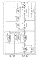
- FIG. 3 shows a configuration example (first embodiment) of the present invention
- the control unit 100 controls the steering torque Th, the vehicle speed Vel, the steering angle ⁇ , the steering angular velocity (motor angular velocity) ⁇ , and the steering angular acceleration (motor angular acceleration
- Torque system control unit 110 includes current command value calculation unit 111, differential control unit 112, yaw rate convergence control unit 113, robust stabilization compensation unit 114, self aligning torque (SAT) compensation value calculation unit 150, and steering reaction force compensation
- the value calculating unit 160 is configured to include adding units 116A and 116B and a subtracting unit 116C.
- Motor system control unit 120 includes compensation unit 121, disturbance estimation unit 122, motor angular velocity calculation unit 123, motor angular acceleration calculation unit 124, and motor characteristic compensation unit 125, and includes addition units 126A and 126B. .
- the steering torque Th is input to the current command value calculation unit 111, the differential control unit 112, the yaw rate convergence control unit 113, and the SAT compensation value calculation unit 150
- the vehicle speed Vel is input to the current command value calculation unit 111 to control the yaw rate convergence.
- the unit 113 uses the vehicle speed Vel as a parameter input.
- the current command value calculation unit 111 calculates the current command value Ia based on the steering torque Th and the vehicle speed Vel, and the differential control unit 112 improves the response of control near the neutral point of steering to realize smooth and smooth steering.
- the output of the differential control unit 112 is added to the current command value Ia by the adding unit 116A, and the current command value Ib which is the addition result is input to the SAT compensation value calculating unit 150, and the adding unit 116B is added. Has entered.
- the yaw rate convergent control unit 113 inputs the steering torque Th and the steering angular velocity ⁇ , and applies a brake to an operation of turning the steering wheel so as to improve the convergence of the yaw of the vehicle.
- the yaw rate signal YR of the yaw rate convergence control unit 113 is added to the current command value Ib by the addition unit 116 B, and the current command value Ic which is the addition result is input to the robust stabilization compensation unit 114.
- the SAT compensation value calculation unit 150 receives the steering torque Th, the current command value Ib from the addition unit 116A, the steering angular velocity ⁇ from the motor angular velocity calculation unit 123, and the steering angle acceleration ⁇ from the motor angular acceleration calculation unit 124.
- the SAT value is estimated, and the estimated SAT value is subjected to signal processing using a filter and a gain unit, and a SAT compensation value ISAT which gives appropriate road surface information as a reaction force to the steering wheel is output.
- the SAT compensation value ISAT is input to the steering reaction force compensation value calculation unit 160, and the steering reaction force compensation value calculation unit 160 is further input with the steering angle ⁇ and the steering angle velocity ⁇ , and the calculated steering reaction force compensation value ISKC Is input to the adding unit 116C.
- the robust stabilization compensating unit 114 is a compensating unit disclosed in, for example, JP-A-8-290778. It removes the peak value at the resonance frequency of the resonance system consisting of the inertia element and the spring element contained in the detected torque, and compensates for the phase shift of the resonance frequency which impairs the response and stability of the control system.
- the current command value Id which is the output of the robust stabilization compensation unit 114 is added to the steering reaction force compensation value ISKC in the adding unit 116C, and the added current command value Ie is input to the adding unit 126A in the motor system control unit 120. Ru.
- the motor angular velocity calculation unit 123 in the motor control unit 120 calculates the steering angular velocity (motor angular velocity) ⁇ based on the voltage Vm between the motor terminals and the motor current Im, and the steering angular velocity ⁇ corresponds to the motor angular acceleration calculation unit 124 and the yaw rate convergence.
- the quality control unit 113 and the SAT compensation value calculation unit 150 are input.
- the motor angular acceleration computing unit 124 computes the steering angular acceleration ⁇ based on the input steering angular velocity ⁇ , and the steering angular acceleration ⁇ is input to the motor characteristic compensating unit 125 and the SAT compensation value computing unit 150.
- the motor characteristic signal Ima from the motor characteristic compensating unit 125 is added to the current command value Ie by the adding unit 126A, and the current command value If which is the addition result is input to the compensating unit 121 formed of a differential compensator or the like.
- a signal obtained by adding the output of the disturbance estimation unit 122 by the addition unit 126B to the current command value Ig compensated by the compensation unit 121 is input to the motor drive unit 23 and the disturbance estimation unit 122.
- the disturbance estimation unit 122 is a device as disclosed in JP-A-8-310417 and is a current obtained by adding the output of the disturbance estimation unit 122 to the current command value Ig compensated by the compensation unit 121 which is a control target of the motor output. Based on the command value Ih and the motor current value Im, the desired motor control characteristic in the output reference of the control system can be maintained, and the stability of the control system is not lost.
- FIG. 4 shows a configuration example of the SAT compensation value calculation unit 150, the current command value Ib corresponding to the assist force Tm and the steering torque Th are added by the addition unit 151, and the addition result shows that the motor has A signal obtained by multiplying the inertia J is subtracted by the subtracting unit 152, and a signal obtained by multiplying the static friction Fr by the positive or negative sign of the steering angular velocity ⁇ is further subtracted by the subtracting unit 153 from the subtraction result.
- the subtraction result of the subtraction unit 153 is the SAT estimated value * SAT (for example, Japanese Patent Laid-Open No. 2008-18825), and the SAT estimated value * SAT is input to the vehicle speed sensitive type filter 154 having frequency characteristics.
- the SAT compensation value ISAT is obtained by multiplying the gain in the gain unit 155 of
- the filter 154 is a phase delay filter having a gain for reducing the magnitude of the SAT estimated value * SAT to a necessary and sufficient value as the static characteristic gain. Further, the gain unit 155 has a function of reducing the SAT compensation value ISAT when the importance of road surface information such as stationary and low speed driving is relatively low.
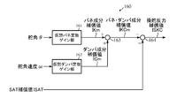
- FIG. 5 shows a configuration example of the steering reaction force compensation value calculation unit 160, and the steering angle ⁇ is input to a virtual spring constant gain unit 161 having a vehicle speed sensitive type characteristic as shown in FIG. 6, for example.
- the steering angular velocity ⁇ is input to, for example, a virtual damper constant gain unit 162 having a vehicle speed sensitive characteristic as shown in FIG.
- the spring component compensation value IKm from the virtual spring constant gain unit 161 and the damper component compensation value ICm from the virtual damper constant gain unit 162 are added by the addition unit 163, and the spring / damper component compensation value IKCm as the addition result is subtracted from the subtraction unit 164 Is subtracted into.
- the force compensation value ISKC is input to the adding unit 116C.
- the virtual spring constant gain part 161 is a vehicle speed sensitive type in FIG. 6, it may not be a vehicle speed sensitive type.
- the virtual damper constant gain unit 162 is the vehicle speed sensitive type in FIG. 7, it may not be the vehicle speed sensitive type.
- the steering torque Th, the vehicle speed Vel, the steering angle ⁇ and the steering angular velocity ⁇ are input (step S1), and the current command value computing unit 121, the differential control unit 122, etc. compute the current command value Ib (step S2).
- the yaw rate signal YR is calculated by the convergence control unit 113, and the current command value Ic to which the yaw rate signal YR is added is output as the current command value Id through the robust stabilization compensation unit 124.
- SAT compensation value calculation unit 150 Current command value Ib and steering angle acceleration ⁇ calculated by motor angular acceleration calculation unit 124 are input to SAT compensation value calculation unit 150 (step S3), and SAT estimated value * SAT is calculated by addition units 151 and 152 and subtraction unit 153. It is calculated (step S4).
- the SAT estimated value * SAT is subjected to filter and gain processing by the filter 154 and the gain unit 155 (step S5), and the SAT compensation value ISAT is output and input to the steering reaction force compensation value calculation unit 160 (step S6).
- the steering reaction force compensation value calculation unit 160 calculates the spring component compensation value IKm according to the steering angle ⁇ in the virtual spring constant gain unit 161 (step S10), and the damper according to the steering angular velocity ⁇ in the virtual damper constant gain unit 162
- the component compensation value ICm is calculated (step S11), and the spring component compensation value IKm and the damper component compensation value ICm are added by the adding unit 163, and the spring / damper component compensation value IKCm as the addition result is SAT by the subtracting unit 164.
- a steering reaction force compensation value ISKC is calculated by subtracting it from the compensation value ISAT and output (step S12).
- the steering reaction force compensation value ISKC is input to the adding unit 116C and added to the current command value Id, and the adding unit 126A adds the motor characteristic signal Ima to drive the motor 20 through the compensating unit 121 and the motor driving unit 23. (Step S20), and the above operation is repeated until it is completed (step S21).
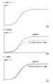
- FIG. 9 is a characteristic diagram showing an operation example of the present invention (first embodiment), and in the case where the steering angle ⁇ is varied with the steering pattern characteristic shown in FIG. 9A, the solid line in FIG.
- the steering torque can be changed to the steering angle and the steering angle by the steering reaction force compensation, although the characteristics are large differences such as (normal road) and broken line (slippery road surface in rainy weather, low As control is made to have a value corresponding to the angular velocity, it is almost independent of the road surface, as shown by the solid line (normal road) and broken line (slippery road such as rainy weather, low ⁇ road) in FIG. It becomes a fixed characteristic.
- the SAT compensation value may be processed directly by the filter and gain unit to a value at which the rack force and the intermediate torque are detected.
- the steering angle may be an angle sensor attached to the steering wheel portion, or may be calculated from an angle sensor attached to the column side or a motor angle.
- the torsion angle of the torsion bar is controlled to follow a value according to the steering angle, and a desired steering torque is obtained.
- FIG. 10 shows a second embodiment of the present invention, where the steering angle ⁇ h is input to the torsion angle table 210, and the target torsion angle ⁇ ref calculated by the torsion angle table 210 according to the steering angle ⁇ h is a torsion angle control unit It is input to 220.
- the actual torsion angle ⁇ from the torsion bar of the EPS (steering) system 200 is input to the torsion angle control unit 220, and the torsion angle control unit 220 receives the motor current command value according to the difference between the target torsion angle ⁇ ref and the actual torsion angle ⁇ .
- Iref is calculated, and based on the calculated motor current command value Iref, the EPS (steering) system 200 is driven such that the actual twist angle ⁇ becomes the target twist angle ⁇ ref.
- the twist angle table 210 outputs a target twist angle ⁇ ref in accordance with the input steering angle ⁇ h. That is, as the steering angle ⁇ h increases in the positive or negative direction, a target twist angle ⁇ ref that gradually increases in the positive or negative direction is output.
- the output characteristic is desirably non-linear as shown in FIG. 10, but may be linear.
- the torsion angle control unit 220 is configured as shown in FIG. 11, for example. There is.
- the target twist angle ⁇ ref is additionally input to the subtractor 221, and the actual twist angle ⁇ is input to the subtractor 221 as well as being input to the differentiator 223 and time-differentiated.
- the deviation of the target torsion angle ⁇ ref and the actual torsion angle ⁇ calculated by the subtraction unit 221 is input to the position control unit 222 of the position control gain Kpp and multiplied by the position control gain Kpp to obtain the target torsion angular velocity ⁇ r.
- the target torsional angular velocity ⁇ r is additionally input to the subtraction unit 224-1 in the speed control unit 224 of the next stage, and the differential value of the differentiation unit 223 is subtracted and input to the subtraction unit 224-1 in the speed control unit 224.
- the control gain Kvp is input to the proportional control calculation unit 224-3.
- the motor current command value Iref is output with the maximum value limited.
- the motor current command value Iref becomes a command value of the EPS system 200 to drive the motor.
- the steering angle ⁇ h is input to the torsion angle table 210 (step S30), the torsion angle table 210 calculates the target torsion angle ⁇ ref according to the steering angle ⁇ h, and inputs the target torsion angle ⁇ ref to the subtraction unit 221 (step S31) ). Further, the real torsion angle ⁇ is detected by the torsion bar of the EPS system 200 (step S 32), and is input to the subtraction unit 221.
- the deviation of the target torsion angle ⁇ ref and the actual torsion angle ⁇ is calculated by the subtraction unit 221 (step S33), the deviation is input to the position control unit 222, and the position control gain Kpp is multiplied to calculate the target torsion angular velocity ⁇ r. (Step S34).
- the real twist angle ⁇ from the EPS system 200 is time-differentiated by the differentiator 223 (step S35), and the result of this differentiation and the target twist angular velocity ⁇ r from the position controller 222 are input to the velocity controller 220, and velocity control is performed. Is performed (step S36).
- the speed control unit 220 of this embodiment has an IP control structure, and the maximum value of the current value Ir obtained by IP control is limited by the limiter 225 (step S37), and the obtained motor current command value Iref
- the EPS system 200 is driven (step S38), and the above operation is repeated until the process is completed.
- the speed control unit 224 first determines the deviation of the target torsional angular velocity ⁇ r and the differentiation result from the differentiation unit 223 by the subtraction unit 224-1, and integrates the deviation by the integration control calculation unit 224-2 by multiplying the integration control gain Kvi.
- the integration control result SC1 is added to the subtraction unit 224-4.
- the differential result is input to the proportional control calculation unit 224-3 and multiplied by the proportional control gain Kvp to perform proportional control calculation, and the proportional control result SC2 is subtracted and input to the subtraction unit 224-4, and the subtraction unit 224-4
- "the integral control result SC1-proportional control result SC2" is calculated to obtain the current value Ir.
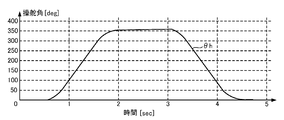
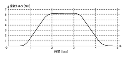
- 13 to 15 are characteristic diagrams showing an operation example of the second embodiment, and when the steering angle ⁇ h is changed with the characteristics shown in FIG. 13, the target twist angle ⁇ ref like the thin line in FIG. It is output from 210. Then, the torsion angle .DELTA..theta. (Thick line) follows the target torsion angle .DELTA..theta.ref (thin line), and as a result, the steering torque appearing in the hand feel is as shown in FIG.
- the above-described torsion angle table 210 has a characteristic corresponding to only the steering angle ⁇ h, it may be a vehicle speed sensitive type that changes according to the vehicle speed V. In the case of the vehicle speed sensitive type table, as shown in FIG. 16, the target twist angle ⁇ ref is generally increased as the vehicle speed V becomes higher.
- a phase compensation unit may be provided at the front stage or rear stage of the torsion angle table 210, and the current command value of the conventional assist control may be added to the motor current command value of torsion angle control.
- the current command value of the SAT estimated value or the current command value for suppressing the steering wheel vibration may be added to the motor current command value of torsion angle control.
- the speed control unit is not limited to the above-described IP control structure, and may be PI control, P control, PID control, or PI-D control.
Landscapes
- Engineering & Computer Science (AREA)
- Chemical & Material Sciences (AREA)
- Combustion & Propulsion (AREA)
- Transportation (AREA)
- Mechanical Engineering (AREA)
- Steering Control In Accordance With Driving Conditions (AREA)
- Power Steering Mechanism (AREA)
Abstract
Description
2 コラム軸(ステアリングシャフト、ハンドル軸)
10 トルクセンサ
12 車速センサ
13 バッテリ
20 モータ
23 モータ駆動部
30、100 コントロールユニット(ECU)
31 電流指令値演算部
35 PI制御部
36 PWM制御部
110 トルク系制御部
111 電流指令値演算部
120 モータ系制御部
122 外乱推定部
150 SAT推定値演算部
160 操舵反力補償値演算部
161 仮想バネ定数ゲイン部
162 仮想ダンパ定数ゲイン部
200 EPS(操舵)系
210 捩れ角テーブル
220 捩れ角制御部
222 位置制御部
224 速度制御部 1
31 Current command
Claims (13)
- 操舵トルク及び車速に基づいて演算された電流指令値に基づいてモータを駆動することにより、操舵系をアシスト制御する電動パワーステアリング装置において、
SAT値に基づいてSAT補償値を演算するSAT補償値演算部と、
前記SAT補償値、舵角及び舵角速度に基づいて操舵反力補償値を演算する操舵反力補償値演算部と、
を備え、前記操舵反力補償値で前記電流指令値を補正することを特徴とする電動パワーステアリング装置。 In an electric power steering apparatus that assists and controls a steering system by driving a motor based on a current command value calculated based on a steering torque and a vehicle speed,
A SAT compensation value calculator that calculates a SAT compensation value based on the SAT value;
A steering reaction force compensation value calculation unit that calculates a steering reaction force compensation value based on the SAT compensation value, the steering angle, and the steering angle speed;
An electric power steering apparatus comprising: the steering reaction force compensation value to correct the current command value. - 前記操舵反力補償値演算部が、
前記舵角を入力してバネ成分補償値を算出する仮想バネ定数ゲイン部と、前記舵角速度を入力してダンパ成分補償値を算出する仮想ダンパ定数ゲイン部と、前記バネ成分補償値及び前記ダンパ成分補償値を加算してバネ・ダンパ成分補償値を算出する加算部と、前記SAT補償値から前記バネ・ダンパ成分補償値を減算して前記操舵反力補償値を算出する減算部とで構成されている請求項1に記載の電動パワーステアリング装置。 The steering reaction force compensation value calculation unit
A virtual spring constant gain unit which calculates a spring component compensation value by inputting the steering angle, a virtual damper constant gain unit which calculates a damper component compensation value by inputting the steering angle velocity, the spring component compensation value and the damper Consists of an addition unit that calculates a spring / damper component compensation value by adding a component compensation value, and a subtraction unit that calculates the steering reaction force compensation value by subtracting the spring / damper component compensation value from the SAT compensation value. The electric power steering apparatus according to claim 1. - 前記SAT補償値演算部が、
前記操舵トルク、モータ角速度、モータ角加速度及び前記電流指令値に基づいてSAT値を求めるSAT推定部と、前記SAT値のノイズを除去するフィルタと、前記フィルタの出力にゲインを乗算して前記SAT補償値を出力するゲイン部とで構成されている請求項1又は2に記載の電動パワーステアリング装置。 The SAT compensation value calculator
A SAT estimation unit for obtaining a SAT value based on the steering torque, motor angular velocity, motor angular acceleration, and the current command value, a filter for removing noise of the SAT value, and an output of the filter The electric power steering apparatus according to claim 1, further comprising: a gain unit that outputs the compensation value. - 前記フィルタ及びゲイン部が車速感応型になっている請求項3に記載の電動パワーステアリング装置。 The electric power steering apparatus according to claim 3, wherein the filter and the gain unit are vehicle speed sensitive.
- 前記仮想バネ定数ゲイン部及び仮想ダンパ定数ゲイン部が車速感応型になっている請求項1乃至3のいずれかに記載の電動パワーステアリング装置。 The electric power steering apparatus according to any one of claims 1 to 3, wherein the virtual spring constant gain part and the virtual damper constant gain part are vehicle speed sensitive.
- 前記補正が、前記電流指令値への前記操舵反力補償値の加算である請求項1乃至5のいずれかに記載の電動パワーステアリング装置。 The electric power steering apparatus according to any one of claims 1 to 5, wherein the correction is addition of the steering reaction force compensation value to the current command value.
- モータ電流指令値に基づいてモータを駆動し、前記モータの駆動制御によって操舵系をアシスト制御する電動パワーステアリング装置において、
操舵角に応じた目標捩れ角及び前記操舵系の実捩れ角の偏差と、前記実捩れ角とに基づく捩れ角制御演算で前記モータ電流指令値を演算し、前記実捩れ角を操舵角に応じた値に追従するように制御することを特徴とする電動パワーステアリング装置。 In an electric power steering apparatus that drives a motor based on a motor current command value and assists and controls a steering system by drive control of the motor,
The motor current command value is calculated by a twist angle control calculation based on the target twist angle according to the steering angle and the deviation of the actual twist angle of the steering system, and the real twist angle, and the real twist angle is calculated according to the steering angle. An electric power steering apparatus characterized in that it is controlled to follow a different value. - 前記目標捩れ角が、前記操舵角を入力する捩れ角テーブルによって算出される請求項7に記載の電動パワーステアリング装置。 The electric power steering apparatus according to claim 7, wherein the target torsion angle is calculated by a torsion angle table for inputting the steering angle.
- 前記捩れ角テーブルが車速感応型になっている請求項8に記載の電動パワーステアリング装置。 The electric power steering apparatus according to claim 8, wherein the torsion angle table is vehicle speed sensitive.
- 前記捩れ角制御演算が、
前記目標捩れ角及び実捩れ角の偏差を求める減算部と、前記偏差を位置制御して前記目標捩れ角速度を出力する位置制御部と、前記実捩れ角を微分する微分部と、前記目標捩れ角速度及び前記微分の出力を入力して速度制御する速度制御部とで実施される請求項7乃至9のいずれかに記載の電動パワーステアリング装置。 The twist angle control operation is
A subtraction unit for obtaining the deviation of the target torsion angle and the actual torsion angle, a position control unit for position control of the deviation to output the target torsion angular velocity, a differentiation unit for differentiating the actual torsion angle, and the target torsion angular velocity 10. The electric power steering apparatus according to any one of claims 7 to 9, which is implemented by a speed control unit that performs speed control by inputting the output of the differential. - 前記速度制御部が、P制御演算、I制御演算、D制御演算の少なくとも1つ若しくはそれらの組み合わせで実施される請求項10に記載の電動パワーステアリング装置。 The electric power steering apparatus according to claim 10, wherein the speed control unit is implemented by at least one of P control calculation, I control calculation, and D control calculation, or a combination thereof.
- 前記速度制御演算部の後段にリミッタが設けられている請求項10又は11に記載の電動パワーステアリング装置。 The electric power steering apparatus according to claim 10, wherein a limiter is provided downstream of the speed control calculation unit.
- 前記モータ電流指令値に、アシスト制御の電流指令値を加算、若しくはSAT推定値の電流指令値を加算、若しくはハンドル振動抑制のための電流指令値を加算している請求項7乃至12のいずれかに記載の電動パワーステアリング装置。 The current command value for assist control is added to the motor current command value, or the current command value for SAT estimated value is added, or the current command value for suppressing the steering wheel vibration is added. The electric power steering apparatus according to claim 1.
Priority Applications (5)
| Application Number | Priority Date | Filing Date | Title |
|---|---|---|---|
| US15/324,813 US10179601B2 (en) | 2014-08-22 | 2015-08-04 | Electric power steering apparatus |
| CN201580044495.0A CN106573647B (en) | 2014-08-22 | 2015-08-04 | Electric power steering apparatus |
| EP15833709.7A EP3184402B1 (en) | 2014-08-22 | 2015-08-04 | Electric power steering device |
| JP2016543896A JP6079942B2 (en) | 2014-08-22 | 2015-08-04 | Electric power steering device |
| US15/941,537 US10300942B2 (en) | 2014-08-22 | 2018-03-30 | Electric power steering apparatus |
Applications Claiming Priority (4)
| Application Number | Priority Date | Filing Date | Title |
|---|---|---|---|
| JP2014-169511 | 2014-08-22 | ||
| JP2014-169512 | 2014-08-22 | ||
| JP2014169512 | 2014-08-22 | ||
| JP2014169511 | 2014-08-22 |
Related Child Applications (2)
| Application Number | Title | Priority Date | Filing Date |
|---|---|---|---|
| US15/324,813 A-371-Of-International US10179601B2 (en) | 2014-08-22 | 2015-08-04 | Electric power steering apparatus |
| US15/941,537 Division US10300942B2 (en) | 2014-08-22 | 2018-03-30 | Electric power steering apparatus |
Publications (1)
| Publication Number | Publication Date |
|---|---|
| WO2016027663A1 true WO2016027663A1 (en) | 2016-02-25 |
Family
ID=55350609
Family Applications (1)
| Application Number | Title | Priority Date | Filing Date |
|---|---|---|---|
| PCT/JP2015/072136 WO2016027663A1 (en) | 2014-08-22 | 2015-08-04 | Electric power steering device |
Country Status (5)
| Country | Link |
|---|---|
| US (2) | US10179601B2 (en) |
| EP (1) | EP3184402B1 (en) |
| JP (1) | JP6079942B2 (en) |
| CN (2) | CN109572807B (en) |
| WO (1) | WO2016027663A1 (en) |
Cited By (11)
| Publication number | Priority date | Publication date | Assignee | Title |
|---|---|---|---|---|
| CN108216351A (en) * | 2016-12-09 | 2018-06-29 | 现代自动车株式会社 | Steering feeling in wire-controlled steering system is by control device |
| WO2018168891A1 (en) * | 2017-03-16 | 2018-09-20 | 日本精工株式会社 | Electric power steering device |
| JPWO2018084190A1 (en) * | 2016-11-07 | 2019-03-14 | 日本精工株式会社 | Electric power steering device |
| WO2019082835A1 (en) * | 2017-10-24 | 2019-05-02 | 日本精工株式会社 | Vehicle steering device |
| EP3460991A4 (en) * | 2016-07-20 | 2019-07-03 | NSK Ltd. | Electric power steering device |
| WO2019167661A1 (en) * | 2018-02-27 | 2019-09-06 | 日本精工株式会社 | Vehicle steering device |
| WO2019193976A1 (en) * | 2018-04-06 | 2019-10-10 | 日本精工株式会社 | Vehicle steering apparatus |
| JP2020055358A (en) * | 2018-09-28 | 2020-04-09 | 日本電産株式会社 | Steering controller and power steering system |
| WO2020213285A1 (en) * | 2019-04-15 | 2020-10-22 | 日本精工株式会社 | Vehicle steering apparatus |
| US20200361526A1 (en) * | 2019-05-14 | 2020-11-19 | Volkswagen Aktiengesellschaft | Method And Steering Control Apparatus For Determining A Correcting Variable For Adjusting Servo Steering Torque In A Vehicle Steering System |
| CN113371061A (en) * | 2020-03-09 | 2021-09-10 | 日本电产株式会社 | Control device, control method, and motor module |
Families Citing this family (14)
| Publication number | Priority date | Publication date | Assignee | Title |
|---|---|---|---|---|
| US9751558B2 (en) * | 2015-03-25 | 2017-09-05 | Ford Global Technologies, Llc | Handwheel obstruction detection and inertia compensation |
| KR101684513B1 (en) * | 2015-04-28 | 2016-12-08 | 현대자동차 주식회사 | Device for controlling restoration of MDPS system |
| KR102350043B1 (en) * | 2015-11-20 | 2022-01-12 | 주식회사 만도 | System and method for controlling autonomous steering |
| JP6279121B1 (en) * | 2017-03-24 | 2018-02-14 | 株式会社ショーワ | Control device and steering device |
| US10889320B2 (en) * | 2017-08-07 | 2021-01-12 | Mando Corporation | Electric power-assisted steering apparatus and method of controlling the same |
| DE102019108996A1 (en) | 2018-04-05 | 2019-10-10 | Steering Solutions Ip Holding Corporation | CASCADED POSITION CONTROL ARCHITECTURE FOR STEERING SYSTEMS |
| US11180187B2 (en) * | 2018-04-27 | 2021-11-23 | Jtekt Corporation | Motor control device |
| JP7155616B2 (en) * | 2018-06-01 | 2022-10-19 | 株式会社ジェイテクト | steering controller |
| WO2020170602A1 (en) * | 2019-02-19 | 2020-08-27 | 日本精工株式会社 | Vehicle steering device |
| JP7170971B2 (en) * | 2019-04-18 | 2022-11-15 | 日本精工株式会社 | Vehicle steering system controller |
| CN114245781B (en) * | 2019-06-07 | 2024-05-10 | 汉拿万都株式会社 | Steering control device, steering control method, and steering support system |
| KR102646187B1 (en) * | 2019-06-11 | 2024-03-11 | 현대모비스 주식회사 | Apparatus for steering by wire of vehicle and control method thereof |
| CN110316247B (en) * | 2019-07-25 | 2021-04-27 | 辽宁工业大学 | Electric power differential compensation steering control method for four-wheel independent drive electric automobile |
| CN113104100B (en) * | 2021-05-27 | 2022-07-19 | 清华大学 | Control method and system for energy-saving intelligent electro-hydraulic steering system |
Citations (4)
| Publication number | Priority date | Publication date | Assignee | Title |
|---|---|---|---|---|
| JP2002104210A (en) * | 2000-09-28 | 2002-04-10 | Toyoda Mach Works Ltd | Controller for electric power steering device |
| JP2005125890A (en) * | 2003-10-22 | 2005-05-19 | Denso Corp | Vehicular electric power steering control device |
| JP2008018825A (en) * | 2006-07-12 | 2008-01-31 | Nsk Ltd | Control device for electric power steering device |
| JP2009143366A (en) * | 2007-12-13 | 2009-07-02 | Nsk Ltd | Electric power steering device |
Family Cites Families (37)
| Publication number | Priority date | Publication date | Assignee | Title |
|---|---|---|---|---|
| JPH0656046A (en) * | 1992-08-11 | 1994-03-01 | Honda Motor Co Ltd | Motor-driven power steering device |
| US6240350B1 (en) * | 1998-07-24 | 2001-05-29 | Nsk Ltd. | Control apparatus for electric power steering system |
| JP3497746B2 (en) * | 1998-10-26 | 2004-02-16 | 本田技研工業株式会社 | Electric power steering device |
| JP3625391B2 (en) * | 1999-04-07 | 2005-03-02 | 三菱電機株式会社 | Vehicle steering angle control device |
| JP4670161B2 (en) * | 2000-07-13 | 2011-04-13 | マツダ株式会社 | Electric power steering device for automobile |
| JP4248739B2 (en) * | 2000-08-30 | 2009-04-02 | 三菱電機株式会社 | Electric power steering control device and control method thereof |
| KR100468493B1 (en) * | 2000-11-24 | 2005-01-27 | 주식회사 만도 | Method for operating electric power steering system of automobile |
| JP4293734B2 (en) * | 2001-01-17 | 2009-07-08 | 三菱電機株式会社 | Electric power steering control device |
| JP3689046B2 (en) * | 2002-01-25 | 2005-08-31 | カヤバ工業株式会社 | Power steering device |
| JP4400270B2 (en) * | 2004-03-19 | 2010-01-20 | 日産自動車株式会社 | Steering angle ratio control device for vehicle |
| JP4779495B2 (en) * | 2004-10-27 | 2011-09-28 | 日産自動車株式会社 | Vehicle steering system |
| EP2256020B1 (en) * | 2005-01-14 | 2013-06-05 | NSK Ltd. | Control apparatus for electric power steering apparatus |
| JP4872298B2 (en) * | 2005-10-04 | 2012-02-08 | 日本精工株式会社 | Control device for electric power steering device |
| JP2007168756A (en) * | 2005-12-26 | 2007-07-05 | Showa Corp | Electric power steering device |
| JP4984602B2 (en) * | 2006-03-31 | 2012-07-25 | 日本精工株式会社 | Control device for electric power steering device |
| JP4957071B2 (en) * | 2006-05-08 | 2012-06-20 | 日本精工株式会社 | Control device for electric power steering device |
| JP2008189006A (en) * | 2007-01-31 | 2008-08-21 | Jtekt Corp | Electric power steering device |
| JP5092603B2 (en) * | 2007-07-20 | 2012-12-05 | 株式会社ジェイテクト | Vehicle steering system |
| EP2216234B1 (en) * | 2007-11-19 | 2016-04-13 | Toyota Jidosha Kabushiki Kaisha | Vehicle steering control device |
| JP5003427B2 (en) * | 2007-11-20 | 2012-08-15 | トヨタ自動車株式会社 | Steering control device and vehicle steering device using the same |
| EP2221236B1 (en) * | 2007-12-14 | 2014-08-06 | Mitsubishi Electric Corporation | Electric power-steering controller |
| JP5074971B2 (en) | 2008-03-24 | 2012-11-14 | 三菱電機株式会社 | Vehicle steering system |
| WO2009139180A1 (en) * | 2008-05-16 | 2009-11-19 | 本田技研工業株式会社 | Electric power steering device |
| JP5534292B2 (en) * | 2008-06-30 | 2014-06-25 | 株式会社ジェイテクト | Vehicle steering system |
| JP2010095075A (en) * | 2008-10-15 | 2010-04-30 | Jtekt Corp | Vehicle steering apparatus |
| WO2010073367A1 (en) * | 2008-12-26 | 2010-07-01 | トヨタ自動車株式会社 | Power steering device |
| WO2010073371A1 (en) * | 2008-12-26 | 2010-07-01 | トヨタ自動車株式会社 | Power steering device |
| JP5421019B2 (en) * | 2009-08-03 | 2014-02-19 | トヨタ自動車株式会社 | Vehicle travel support device |
| JP5208894B2 (en) | 2009-09-14 | 2013-06-12 | 株式会社豊田中央研究所 | Vehicle control device, steering simulation device, and program |
| EP2322410B1 (en) * | 2009-09-28 | 2017-04-19 | NSK Ltd. | Electric power steering device |
| CN102770328B (en) * | 2010-02-19 | 2014-12-03 | 三菱电机株式会社 | Steering controller |
| WO2012073760A1 (en) * | 2010-11-29 | 2012-06-07 | 本田技研工業株式会社 | Electronic power steering apparatus |
| EP2626278B1 (en) * | 2010-11-29 | 2015-07-22 | Honda Motor Co., Ltd. | Electronic power steering apparatus |
| JP5212454B2 (en) * | 2010-12-06 | 2013-06-19 | 日本精工株式会社 | Control device for electric power steering device |
| JP5224419B2 (en) * | 2011-02-09 | 2013-07-03 | 本田技研工業株式会社 | Electric power steering device |
| EP2985206B1 (en) * | 2013-04-08 | 2017-10-04 | Mitsubishi Electric Corporation | Steering control device, and steering control method |
| US9540040B2 (en) * | 2014-06-26 | 2017-01-10 | Steering Solutions Ip Holding Corporation | Phase plane based transitional damping for electric power steering |
-
2015
- 2015-08-04 EP EP15833709.7A patent/EP3184402B1/en active Active
- 2015-08-04 JP JP2016543896A patent/JP6079942B2/en active Active
- 2015-08-04 CN CN201811395760.1A patent/CN109572807B/en active Active
- 2015-08-04 CN CN201580044495.0A patent/CN106573647B/en active Active
- 2015-08-04 US US15/324,813 patent/US10179601B2/en active Active
- 2015-08-04 WO PCT/JP2015/072136 patent/WO2016027663A1/en active Application Filing
-
2018
- 2018-03-30 US US15/941,537 patent/US10300942B2/en active Active
Patent Citations (4)
| Publication number | Priority date | Publication date | Assignee | Title |
|---|---|---|---|---|
| JP2002104210A (en) * | 2000-09-28 | 2002-04-10 | Toyoda Mach Works Ltd | Controller for electric power steering device |
| JP2005125890A (en) * | 2003-10-22 | 2005-05-19 | Denso Corp | Vehicular electric power steering control device |
| JP2008018825A (en) * | 2006-07-12 | 2008-01-31 | Nsk Ltd | Control device for electric power steering device |
| JP2009143366A (en) * | 2007-12-13 | 2009-07-02 | Nsk Ltd | Electric power steering device |
Cited By (29)
| Publication number | Priority date | Publication date | Assignee | Title |
|---|---|---|---|---|
| US10494017B2 (en) | 2016-07-20 | 2019-12-03 | Nsk Ltd. | Electric power steering apparatus |
| EP3460991A4 (en) * | 2016-07-20 | 2019-07-03 | NSK Ltd. | Electric power steering device |
| JPWO2018084190A1 (en) * | 2016-11-07 | 2019-03-14 | 日本精工株式会社 | Electric power steering device |
| US10589780B2 (en) | 2016-11-07 | 2020-03-17 | Nsk Ltd. | Electric power steering apparatus |
| CN108216351A (en) * | 2016-12-09 | 2018-06-29 | 现代自动车株式会社 | Steering feeling in wire-controlled steering system is by control device |
| CN108216351B (en) * | 2016-12-09 | 2021-10-15 | 现代自动车株式会社 | Steering feeling control device in steer-by-wire system |
| JPWO2018168891A1 (en) * | 2017-03-16 | 2019-06-27 | 日本精工株式会社 | Electric power steering device |
| US10661825B2 (en) | 2017-03-16 | 2020-05-26 | Nsk Ltd. | Electric power steering apparatus |
| CN111406011A (en) * | 2017-03-16 | 2020-07-10 | 日本精工株式会社 | Electric power steering apparatus |
| WO2018168891A1 (en) * | 2017-03-16 | 2018-09-20 | 日本精工株式会社 | Electric power steering device |
| WO2019082835A1 (en) * | 2017-10-24 | 2019-05-02 | 日本精工株式会社 | Vehicle steering device |
| JPWO2019082835A1 (en) * | 2017-10-24 | 2020-04-02 | 日本精工株式会社 | Vehicle steering system |
| CN111406012B (en) * | 2017-10-24 | 2021-12-21 | 日本精工株式会社 | Steering device for vehicle |
| CN111406012A (en) * | 2017-10-24 | 2020-07-10 | 日本精工株式会社 | Steering device for vehicle |
| US11034382B2 (en) | 2017-10-24 | 2021-06-15 | Nsk Ltd. | Steering apparatus for vehicles |
| WO2019167661A1 (en) * | 2018-02-27 | 2019-09-06 | 日本精工株式会社 | Vehicle steering device |
| JPWO2019167661A1 (en) * | 2018-02-27 | 2021-03-25 | 日本精工株式会社 | Vehicle steering device |
| WO2019193976A1 (en) * | 2018-04-06 | 2019-10-10 | 日本精工株式会社 | Vehicle steering apparatus |
| JPWO2019193976A1 (en) * | 2018-04-06 | 2021-07-15 | 日本精工株式会社 | Vehicle steering device |
| JP7153244B2 (en) | 2018-04-06 | 2022-10-14 | 日本精工株式会社 | vehicle steering system |
| JP2020055358A (en) * | 2018-09-28 | 2020-04-09 | 日本電産株式会社 | Steering controller and power steering system |
| JP7247508B2 (en) | 2018-09-28 | 2023-03-29 | 日本電産株式会社 | Steering control device and power steering device |
| JP2020175693A (en) * | 2019-04-15 | 2020-10-29 | 日本精工株式会社 | Steering system for vehicles |
| WO2020213285A1 (en) * | 2019-04-15 | 2020-10-22 | 日本精工株式会社 | Vehicle steering apparatus |
| JP7153239B2 (en) | 2019-04-15 | 2022-10-14 | 日本精工株式会社 | vehicle steering system |
| US20200361526A1 (en) * | 2019-05-14 | 2020-11-19 | Volkswagen Aktiengesellschaft | Method And Steering Control Apparatus For Determining A Correcting Variable For Adjusting Servo Steering Torque In A Vehicle Steering System |
| US11565742B2 (en) * | 2019-05-14 | 2023-01-31 | Volkswagen Aktiengesellschaft | Method and steering control apparatus for determining a correcting variable for adjusting servo steering torque in a vehicle steering system |
| CN113371061A (en) * | 2020-03-09 | 2021-09-10 | 日本电产株式会社 | Control device, control method, and motor module |
| CN113371061B (en) * | 2020-03-09 | 2023-06-09 | 日本电产株式会社 | Control device, control method and motor module |
Also Published As
| Publication number | Publication date |
|---|---|
| CN109572807A (en) | 2019-04-05 |
| JP6079942B2 (en) | 2017-02-15 |
| CN106573647A (en) | 2017-04-19 |
| EP3184402B1 (en) | 2020-04-15 |
| CN109572807B (en) | 2021-04-09 |
| EP3184402A1 (en) | 2017-06-28 |
| CN106573647B (en) | 2019-04-26 |
| US20180222521A1 (en) | 2018-08-09 |
| EP3184402A4 (en) | 2018-04-11 |
| US10300942B2 (en) | 2019-05-28 |
| US20170217479A1 (en) | 2017-08-03 |
| JPWO2016027663A1 (en) | 2017-04-27 |
| US10179601B2 (en) | 2019-01-15 |
Similar Documents
| Publication | Publication Date | Title |
|---|---|---|
| WO2016027663A1 (en) | Electric power steering device | |
| JP5896091B1 (en) | Electric power steering device | |
| US9446789B2 (en) | Electric power steering apparatus | |
| JP5880801B1 (en) | Electric power steering device | |
| JP6098764B2 (en) | Electric power steering device | |
| JP5109342B2 (en) | Electric power steering device | |
| JP4872298B2 (en) | Control device for electric power steering device | |
| WO2019193976A1 (en) | Vehicle steering apparatus | |
| WO2014162769A1 (en) | Electric power steering device | |
| WO2018142650A1 (en) | Electric power steering apparatus | |
| WO2019026351A1 (en) | Electric power steering device | |
| WO2020122200A1 (en) | Electric power steering device | |
| JP6702513B2 (en) | Steering device for vehicle | |
| JP6565847B2 (en) | Electric power steering device | |
| US20160318548A1 (en) | Electric power steering apparatus | |
| WO2015170559A1 (en) | Electric power steering device | |
| WO2020145036A1 (en) | Vehicle steering device | |
| WO2019082271A1 (en) | Electric power steering apparatus | |
| US20170080969A1 (en) | Electric power steering apparatus | |
| WO2020100411A1 (en) | Vehicle steering device | |
| JP4715446B2 (en) | Control device for electric power steering device | |
| JP5056162B2 (en) | Control device for electric power steering device | |
| WO2019167661A1 (en) | Vehicle steering device | |
| JP4696572B2 (en) | Control device for electric power steering device | |
| JP7222309B2 (en) | vehicle steering system |
Legal Events
| Date | Code | Title | Description |
|---|---|---|---|
| ENP | Entry into the national phase |
Ref document number: 2016543896 Country of ref document: JP Kind code of ref document: A |
|
| 121 | Ep: the epo has been informed by wipo that ep was designated in this application |
Ref document number: 15833709 Country of ref document: EP Kind code of ref document: A1 |
|
| WWE | Wipo information: entry into national phase |
Ref document number: 15324813 Country of ref document: US |
|
| REEP | Request for entry into the european phase |
Ref document number: 2015833709 Country of ref document: EP |
|
| WWE | Wipo information: entry into national phase |
Ref document number: 2015833709 Country of ref document: EP |
|
| NENP | Non-entry into the national phase |
Ref country code: DE |