WO2016018068A1 - Method for transmitting resource information for d2d communication and apparatus therefor in wireless communication system - Google Patents
Method for transmitting resource information for d2d communication and apparatus therefor in wireless communication system Download PDFInfo
- Publication number
- WO2016018068A1 WO2016018068A1 PCT/KR2015/007923 KR2015007923W WO2016018068A1 WO 2016018068 A1 WO2016018068 A1 WO 2016018068A1 KR 2015007923 W KR2015007923 W KR 2015007923W WO 2016018068 A1 WO2016018068 A1 WO 2016018068A1
- Authority
- WO
- WIPO (PCT)
- Prior art keywords
- resource
- information
- signal
- transmitting
- resource information
- Prior art date
Links
Images


Classifications
-
- H—ELECTRICITY
- H04—ELECTRIC COMMUNICATION TECHNIQUE
- H04W—WIRELESS COMMUNICATION NETWORKS
- H04W72/00—Local resource management
- H04W72/02—Selection of wireless resources by user or terminal
-
- H—ELECTRICITY
- H04—ELECTRIC COMMUNICATION TECHNIQUE
- H04W—WIRELESS COMMUNICATION NETWORKS
- H04W72/00—Local resource management
- H04W72/20—Control channels or signalling for resource management
-
- H—ELECTRICITY
- H04—ELECTRIC COMMUNICATION TECHNIQUE
- H04W—WIRELESS COMMUNICATION NETWORKS
- H04W72/00—Local resource management
- H04W72/50—Allocation or scheduling criteria for wireless resources
- H04W72/535—Allocation or scheduling criteria for wireless resources based on resource usage policies
-
- H—ELECTRICITY
- H04—ELECTRIC COMMUNICATION TECHNIQUE
- H04W—WIRELESS COMMUNICATION NETWORKS
- H04W76/00—Connection management
- H04W76/10—Connection setup
- H04W76/11—Allocation or use of connection identifiers
-
- H—ELECTRICITY
- H04—ELECTRIC COMMUNICATION TECHNIQUE
- H04W—WIRELESS COMMUNICATION NETWORKS
- H04W76/00—Connection management
- H04W76/10—Connection setup
- H04W76/14—Direct-mode setup
Definitions
- the present invention relates to a wireless communication system, and more particularly, to a method and apparatus for transmitting resource information for device-to-device (D2D) communication in a wireless communication system.
- D2D device-to-device
- a 3GPP LTE (3rd Generation Partnership Project Long Term Evolution (LTE)) communication system will be described in brief.
- E-UMTS Evolved Universal Mobile Telecommunications System
- UMTS Universal Mobile Telecommunications System
- LTE Long Term Evolution
- an E-UMTS is located at an end of a user equipment (UE) and a base station (eNode B, eNB, network (E-UTRAN)) and connects an access gateway (AG) connected to an external network.
- the base station may transmit multiple data streams simultaneously for broadcast service, multicast service and / or unicast service.
- the cell is set to one of bandwidths such as 1.25, 2.5, 5, 10, 15, and 20Mhz to provide downlink or uplink transmission services to multiple terminals. Different cells may be configured to provide different bandwidths.
- the base station controls data transmission and reception for a plurality of terminals.
- For downlink (DL) data the base station transmits downlink scheduling information to inform the corresponding UE of time / frequency domain, encoding, data size, and HARQ (Hybrid Automatic Repeat and reQuest) related information.
- the base station transmits uplink scheduling information to the terminal for uplink (UL) data, and informs the time / frequency domain, encoding, data size, HARQ related information, etc. that the terminal can use.
- DL downlink
- HARQ Hybrid Automatic Repeat and reQuest
- the core network may be composed of a network node for the user registration of the AG and the terminal.
- the AG manages the mobility of the UE in units of a tracking area (TA) composed of a plurality of cells.
- TA tracking area
- Wireless communication technology has been developed to LTE based on WCDMA, but the demands and expectations of users and operators are continuously increasing.
- new technological evolution is required to be competitive in the future. Reduced cost per bit, increased service availability, the use of flexible frequency bands, simple structure and open interface, and adequate power consumption of the terminal are required.
- the terminal reports the current channel state information periodically and / or aperiodically to the base station in order to assist efficient operation of the base station wireless communication system. Since the state information of the reported channel may include the results calculated in consideration of various situations, a more efficient reporting method is required.
- the present invention proposes a method and apparatus for transmitting resource information for device-to-device (D2D) communication in a wireless communication system.
- D2D device-to-device
- D2D device-to-device
- the resource information may be characterized in that when the D2D transmitting terminal performs the 1 D2D signal transmission, the D2D transmitting terminal indicates a radio resource that can be received.
- the resource information indicates a first radio resource for transmitting the first D2D signal
- the first radio resource is set on a resource pool excluding a second radio resource
- the second radio resource is
- the D2D transmitting terminal may be a radio resource used for transmitting a second D2D signal to the D2D receiving terminal.
- the resource information may be mapped onto a resource pool for scheduling assignment.
- the resource information may be mapped onto a resource pool for D2D data.
- the resource information may be transmitted using a predefined channel, and the resource may be determined based on a D2D terminal identifier (D2D UE ID).
- D2D UE ID D2D terminal identifier
- the resource information may be configured to be masked by a cyclic redundancy check (CRC) based on the D2D UE identifier.
- CRC cyclic redundancy check
- the resource information may be configured to include an identifier information association field of the D2D transmitting terminal.
- the resource information may be configured to be transmitted together with control information for at least one of the first D2D signal transmission or the second D2D signal transmission.
- D2D transmitting terminal for transmitting resource information for device-to-device (D2D) communication in a wireless communication system includes: a radio frequency unit; And a processor, wherein the processor receives a resource pool setting for D2D communication and indicates a resource for transmitting a resource for transmitting a first D2D signal from the D2D receiving terminal to the D2D transmitting terminal It may be configured to transmit information to the D2D receiving terminal.
- resource information for D2D communication may be efficiently transmitted and received in a wireless communication system.
- FIG. 1 schematically illustrates an E-UMTS network structure as an example of a wireless communication system.
- FIG. 2 illustrates a structure of a control plane and a user plane of a radio interface protocol between a terminal and an E-UTRAN based on the 3GPP radio access network standard.
- 3 illustrates physical channels used in a 3GPP system and a general signal transmission method using the same.
- FIG. 4 illustrates a structure of a radio frame used in an LTE system.
- 5 illustrates a resource grid for a downlink slot.
- FIG. 6 illustrates a structure of a downlink radio frame used in an LTE system.
- FIG. 7 illustrates a structure of an uplink subframe used in an LTE system.
- D2D UE-to-UE communication
- FIG. 9 illustrates communication performed by a D2D RUE, which is an HTX D2D UE, according to an embodiment of the present invention.
- FIG. 10 shows a configuration of a resource unit (RU) for D2D communication.
- SA scheduling allocation
- FIG. 12 shows a link between a SIG TX UE and a SIG RX UE in the present invention.
- FIG. 13 is a reference diagram for explaining a case in which NSIG RP appears earlier in the time domain than in OSIG RP according to one embodiment of the present invention.
- FIG. 14 illustrates a base station and a terminal that can be applied to an embodiment of the present invention.
- CDMA code division multiple access
- FDMA frequency division multiple access
- TDMA time division multiple access
- OFDMA orthogonal frequency division multiple access
- SC-FDMA single carrier frequency division multiple access
- CDMA may be implemented with a radio technology such as Universal Terrestrial Radio Access (UTRA) or CDMA2000.
- TDMA may be implemented with wireless technologies such as Global System for Mobile communications (GSM) / General Packet Radio Service (GPRS) / Enhanced Data Rates for GSM Evolution (EDGE).
- GSM Global System for Mobile communications
- GPRS General Packet Radio Service
- EDGE Enhanced Data Rates for GSM Evolution
- OFDMA may be implemented in a wireless technology such as IEEE 802.11 (Wi-Fi), IEEE 802.16 (WiMAX), IEEE 802-20, Evolved UTRA (E-UTRA).
- UTRA is part of the Universal Mobile Telecommunications System (UMTS).
- 3rd Generation Partnership Project (3GPP) long term evolution (LTE) employs OFDMA in downlink and SC-FDMA in uplink as part of Evolved UMTS (E-UMTS) using E-UTRA.
- LTE-A Advanced is an evolution of 3GPP LTE.
- FIG. 2 is a diagram illustrating a control plane and a user plane structure of a radio interface protocol between a terminal and an E-UTRAN based on the 3GPP radio access network standard.
- the control plane refers to a path through which control messages used by a user equipment (UE) and a network to manage a call are transmitted.
- the user plane refers to a path through which data generated at an application layer, for example, voice data or Internet packet data, is transmitted.
- the physical layer which is the first layer, provides an information transfer service to an upper layer by using a physical channel.
- the physical layer is connected to the upper layer of the medium access control layer through a trans-antenna port channel. Data moves between the medium access control layer and the physical layer through the transport channel. Data moves between the physical layer between the transmitting side and the receiving side through the physical channel.
- the physical channel utilizes time and frequency as radio resources. Specifically, the physical channel is modulated in the Orthogonal Frequency Division Multiple Access (OFDMA) scheme in the downlink, and modulated in the Single Carrier Frequency Division Multiple Access (SC-FDMA) scheme in the uplink.
- OFDMA Orthogonal Frequency Division Multiple Access
- SC-FDMA Single Carrier Frequency Division Multiple Access
- the medium access control (MAC) layer of the second layer provides a service to a radio link control (RLC) layer, which is a higher layer, through a logical channel.
- RLC radio link control
- the RLC layer of the second layer supports reliable data transmission.
- the function of the RLC layer may be implemented as a functional block inside the MAC.
- the PDCP (Packet Data Convergence Protocol) layer of the second layer performs a header compression function to reduce unnecessary control information for efficiently transmitting IP packets such as IPv4 or IPv6 in a narrow bandwidth wireless interface.
- IPv4 Packet Data Convergence Protocol
- the Radio Resource Control (RRC) layer located at the bottom of the third layer is defined only in the control plane.
- the RRC layer is responsible for control of logical channels, transport channels, and physical channels in connection with configuration, reconfiguration, and release of radio bearers (RBs).
- RB means a service provided by the second layer for data transmission between the terminal and the network.
- the RRC layers of the UE and the network exchange RRC messages with each other. If there is an RRC connected (RRC Connected) between the UE and the RRC layer of the network, the UE is in an RRC connected mode, otherwise it is in an RRC idle mode.
- the non-access stratum (NAS) layer above the RRC layer performs functions such as session management and mobility management.
- One cell constituting an eNB is set to one of bandwidths such as 1.4, 3, 5, 10, 15, and 20 MHz to provide downlink or uplink transmission services to multiple terminals. Different cells may be configured to provide different bandwidths.
- the downlink transport channel for transmitting data from the network to the UE includes a broadcast channel (BCH) for transmitting system information, a paging channel (PCH) for transmitting a paging message, and a downlink shared channel (SCH) for transmitting user traffic or a control message.
- BCH broadcast channel
- PCH paging channel
- SCH downlink shared channel
- Traffic or control messages of a downlink multicast or broadcast service may be transmitted through a downlink SCH or may be transmitted through a separate downlink multicast channel (MCH).
- the uplink transmission channel for transmitting data from the terminal to the network includes a random access channel (RAC) for transmitting an initial control message and an uplink shared channel (SCH) for transmitting user traffic or a control message.
- RAC random access channel
- SCH uplink shared channel
- BCCH broadcast control channel
- PCCH paging control channel
- CCCH common control channel
- MCCH multicast control channel
- MTCH multicast. Traffic Channel
- FIG. 3 is a diagram for describing physical channels used in a 3GPP LTE system and a general signal transmission method using the same.
- the user equipment that is powered on again or enters a new cell while the power is turned off performs an initial cell search operation such as synchronizing with the base station in step S301.
- the user equipment receives a primary synchronization channel (P-SCH) and a secondary synchronization channel (S-SCH) from the base station, synchronizes with the base station, and obtains information such as a cell ID.
- P-SCH primary synchronization channel
- S-SCH secondary synchronization channel
- the user equipment may receive a physical broadcast channel from the base station to obtain broadcast information in a cell.
- the user equipment may receive a downlink reference signal (DL RS) in the initial cell search step to check the downlink channel state.
- DL RS downlink reference signal
- the user equipment receives the physical downlink control channel (PDCCH) and the physical downlink control channel (PDSCH) according to the physical downlink control channel information in step S302. Specific system information can be obtained.
- PDCCH physical downlink control channel
- PDSCH physical downlink control channel
- the user equipment may perform a random access procedure such as step S303 to step S306 to complete the access to the base station.
- the user equipment transmits a preamble through a physical random access channel (PRACH) (S303), and responds to the preamble through a physical downlink control channel and a corresponding physical downlink shared channel.
- PRACH physical random access channel
- the message may be received (S304).
- contention resolution procedures such as transmission of an additional physical random access channel (S305) and reception of a physical downlink control channel and a corresponding physical downlink shared channel (S306) may be performed. .
- UCI uplink control information
- HARQ ACK / NACK Hybrid Automatic Repeat and reQuest Acknowledgment / Negative-ACK
- SR Scheduling Request
- CSI Channel State Information
- HARQ ACK / NACK is simply referred to as HARQ-ACK or ACK / NACK (A / N).
- HARQ-ACK includes at least one of positive ACK (simply ACK), negative ACK (NACK), DTX, and NACK / DTX.
- the CSI includes a Channel Quality Indicator (CQI), a Precoding Matrix Indicator (PMI), a Rank Indication (RI), and the like.
- CQI Channel Quality Indicator
- PMI Precoding Matrix Indicator
- RI Rank Indication
- UCI is generally transmitted through PUCCH, but may be transmitted through PUSCH when control information and traffic data should be transmitted at the same time. In addition, the UCI may be aperiodically transmitted through the PUSCH by the request / instruction of the network.
- FIG. 4 is a diagram illustrating a structure of a radio frame used in an LTE system.
- uplink / downlink data packet transmission is performed in subframe units, and one subframe is defined as a predetermined time interval including a plurality of OFDM symbols.
- the 3GPP LTE standard supports a type 1 radio frame structure applicable to frequency division duplex (FDD) and a type 2 radio frame structure applicable to time division duplex (TDD).
- the downlink radio frame consists of 10 subframes, and one subframe consists of two slots in the time domain.
- the time taken for one subframe to be transmitted is called a transmission time interval (TTI).
- TTI transmission time interval
- one subframe may have a length of 1 ms
- one slot may have a length of 0.5 ms.
- One slot includes a plurality of OFDM symbols in the time domain and a plurality of resource blocks (RBs) in the frequency domain.
- RBs resource blocks
- a resource block (RB) as a resource allocation unit may include a plurality of consecutive subcarriers in one slot.
- the number of OFDM symbols included in one slot may vary depending on the configuration of a cyclic prefix (CP).
- CPs include extended CPs and normal CPs.
- the number of OFDM symbols included in one slot may be seven.
- the OFDM symbol is configured by the extended CP, since the length of one OFDM symbol is increased, the number of OFDM symbols included in one slot is smaller than that of the standard CP.
- the number of OFDM symbols included in one slot may be six. If the channel state is unstable, such as when the user equipment moves at a high speed, an extended CP may be used to further reduce intersymbol interference.
- one subframe includes 14 OFDM symbols.
- the first up to three OFDM symbols of each subframe may be allocated to a physical downlink control channel (PDCCH), and the remaining OFDM symbols may be allocated to a physical downlink shared channel (PDSCH).
- PDCCH physical downlink control channel
- PDSCH physical downlink shared channel
- Type 2 radio frames consist of two half frames, each half frame comprising four general subframes including two slots, a downlink pilot time slot (DwPTS), a guard period (GP) and It consists of a special subframe including an Uplink Pilot Time Slot (UpPTS).
- DwPTS downlink pilot time slot
- GP guard period
- UpPTS Uplink Pilot Time Slot
- DwPTS is used for initial cell search, synchronization or channel estimation at the user equipment.
- UpPTS is used for channel estimation at base station and synchronization of uplink transmission of user equipment. That is, DwPTS is used for downlink transmission and UpPTS is used for uplink transmission.
- UpPTS is used for PRACH preamble or SRS transmission.
- the guard period is a period for removing interference caused in the uplink due to the multipath delay of the downlink signal between the uplink and the downlink.
- the current 3GPP standard document defines a configuration as shown in Table 1 below.
- Table 1 In the case of DwPTS and UpPTS, the remaining area is set as a protection interval.
- the structure of the type 2 radio frame that is, UL / DL configuration (UL / DL configuration) in the TDD system is shown in Table 2 below.
- D denotes a downlink subframe
- U denotes an uplink subframe
- S denotes the special subframe.
- Table 2 also shows the downlink-uplink switching period in the uplink / downlink subframe configuration in each system.
- the structure of the radio frame described above is merely an example, and the number of subframes included in the radio frame, the number of slots included in the subframe, and the number of symbols included in the slot may be variously changed.
- 5 illustrates a resource grid for a downlink slot.
- the downlink slot is in the time domain Contains OFDM symbols and in the frequency domain Contains resource blocks.
- the number of OFDM symbols included in the downlink slot may be modified according to the length of a cyclic prefix (CP).
- CP cyclic prefix
- Each element on the resource grid is called a Resource Element (RE), and one resource element is indicated by one OFDM symbol index and one subcarrier index.
- the number of resource blocks included in the downlink slot ( ) depends on the downlink transmission bandwidth set in the cell.
- FIG. 6 illustrates a structure of a downlink subframe.
- up to three (4) OFDM symbols located at the front of the first slot of a subframe correspond to a control region to which a control channel is allocated.
- the remaining OFDM symbols correspond to data regions to which the Physical Downlink Shared Channel (PDSCH) is allocated.
- Examples of a downlink control channel used in LTE include a Physical Control Format Indicator Channel (PCFICH), a Physical Downlink Control Channel (PDCCH), a Physical Hybrid ARQ Indicator Channel (PHICH), and the like.
- the PCFICH is transmitted in the first OFDM symbol of a subframe and carries information about the number of OFDM symbols used for transmission of a control channel within the subframe.
- the PHICH carries a HARQ ACK / NACK (Hybrid Automatic Repeat request acknowledgment / negative-acknowledgment) signal in response to uplink transmission.
- DCI downlink control information
- the DCI includes resource allocation information and other control information for the user device or user device group.
- the DCI includes uplink / downlink scheduling information, uplink transmission (Tx) power control command, and the like.
- the PDCCH includes a transmission format and resource allocation information of a downlink shared channel (DL-SCH), a transmission format and resource allocation information of an uplink shared channel (UL-SCH), a paging channel, Resource allocation information of upper-layer control messages such as paging information on PCH), system information on DL-SCH, random access response transmitted on PDSCH, Tx power control command set for individual user devices in a group of user devices, Tx power It carries control commands and activation instruction information of Voice over IP (VoIP).
- a plurality of PDCCHs may be transmitted in the control region.
- the user equipment may monitor the plurality of PDCCHs.
- the PDCCH is transmitted on an aggregation of one or a plurality of consecutive control channel elements (CCEs).
- CCEs control channel elements
- the CCE is a logical allocation unit used to provide a PDCCH with a coding rate based on radio channel conditions.
- the CCE corresponds to a plurality of resource element groups (REGs).
- the format of the PDCCH and the number of PDCCH bits are determined according to the number of CCEs.
- the base station determines the PDCCH format according to the DCI to be transmitted to the user equipment, and adds a cyclic redundancy check (CRC) to the control information.
- the CRC is masked with an identifier (eg, a radio network temporary identifier (RNTI)) according to the owner or purpose of use of the PDCCH.
- RNTI radio network temporary identifier
- an identifier eg, cell-RNTI (C-RNTI)
- C-RNTI cell-RNTI
- P-RNTI paging-RNTI
- SI-RNTI system information RNTI
- RA-RNTI random access-RNTI
- FIG. 7 illustrates a structure of an uplink subframe used in LTE.
- an uplink subframe includes a plurality (eg, two) slots.
- the slot may include different numbers of SC-FDMA symbols according to the CP length.
- the uplink subframe is divided into a data region and a control region in the frequency domain.
- the data area includes a PUSCH and is used to transmit data signals such as voice.
- the control region includes a PUCCH and is used to transmit uplink control information (UCI).
- the PUCCH includes RB pairs located at both ends of the data region on the frequency axis and hops to a slot boundary.
- PUCCH may be used to transmit the following control information.
- SR Service Request: Information used for requesting an uplink UL-SCH resource. It is transmitted using OOK (On-Off Keying) method.
- HARQ ACK / NACK This is a response signal for a downlink data packet on a PDSCH. Indicates whether the downlink data packet was successfully received. One bit of ACK / NACK is transmitted in response to a single downlink codeword, and two bits of ACK / NACK are transmitted in response to two downlink codewords.
- CSI Channel State Information
- the CSI includes a channel quality indicator (CQI), and the feedback information related to multiple input multiple output (MIMO) includes a rank indicator (RI), a precoding matrix indicator (PMI), a precoding type indicator (PTI), and the like. 20 bits are used per subframe.
- CQI channel quality indicator
- MIMO multiple input multiple output
- RI rank indicator
- PMI precoding matrix indicator
- PTI precoding type indicator
- the amount of control information (UCI) that a user equipment can transmit in a subframe depends on the number of SC-FDMAs available for control information transmission.
- SC-FDMA available for transmission of control information means the remaining SC-FDMA symbol except for the SC-FDMA symbol for transmitting the reference signal in the subframe, and in the case of the subframe in which the Sounding Reference Signal (SRS) is set, the last of the subframe SC-FDMA symbols are also excluded.
- the reference signal is used for coherent detection of the PUCCH.
- D2D UE-to-UE Communication
- the D2D communication scheme can be largely divided into a scheme supported by a network / coordination station (for example, a base station) and a case not otherwise.
- a network / coordination station for example, a base station
- FIG. 8A transmission / reception of a control signal (eg, grant message), HARQ, Channel State Information, etc. is performed by a network / coordination station and performs D2D communication.
- a control signal eg, grant message
- HARQ Channel State Information
- FIG. 8 (b) the network provides only minimal information (for example, D2D connection information available in a corresponding cell), but terminals performing D2D communication form a link and transmit and receive data. The way of doing this is shown.
- D2D TX UE when device-to-device (D2D) communication is performed, a UE (hereinafter, referred to as “D2D TX UE”) that transmits a D2D signal receives a D2D signal (hereinafter, referred to as “D2D TX UE”).
- D2D TX UE a UE that transmits a D2D signal receives a D2D signal
- D2D TX UE a UE that transmits a D2D signal receives a D2D signal
- D2D TX UE A method of efficiently transmitting various types of control information to the "D2D RX UE” will be described.
- D2D communication means that the UE communicates directly with another UE using a wireless channel, and furthermore, the UE means a user's terminal, but network equipment such as an eNB transmits / receives signals according to a communication method between the UEs.
- the present invention can be applied as it is
- the determination / determination of whether or not the specific UE corresponds to the HTX D2D UE may be performed by the following methods 1-A to 1-C.
- the UE may be configured to determine itself as an HTX D2D UE when the amount of data / control information to be transmitted in its (D2D) buffer is greater than a predefined or signaled threshold.
- the UE which has determined itself as an HTX D2D UE, may be configured to report information on this to the eNB through a predefined signal (eg, a physical layer signal or a higher layer signal).
- Scheme 1-B Whether or not the UE is an HTX D2D UE through the Buffer Status Report (BSR) information received by the eNB from the specific UE (related to existing or newly defined amount of data / control information to be transmitted) It may be set to determine whether or not, and informs about this information through a predefined signal.
- the eNB having received such BSR information from a specific UE, may determine the UE as an HTX D2D UE if the amount of data / control information to be transmitted by the corresponding UE is greater than or equal to a predefined threshold.
- Method 1-C It may be set to be determined according to the UE type (or type of role performed by the UE).
- a specific UE type (or a role type performed by a specific UE) may be predefined or signaled, and also UEs such as Examples 1-C-1 to 1-C-3 may be referred to as an HTX D2D UE. Can be selected.
- Example 1-C-1 UE that should (re) transmit information received from 'predefined or signaled UE' or 'eNB' to 'predefined or signaled target UE' or 'eNB' , “D2D Relay UE (D2D RUE)”)
- Example 1-C-2 UE that manages / manages D2D group communication of UE group (hereinafter “D2D Group Owner UE (D2D GOUE)”) (eg D2D Synchronization Signal transmission, data transmission / reception Role of sending related resource allocation information)
- D2D Group Owner UE eg D2D Synchronization Signal transmission, data transmission / reception Role of sending related resource allocation information
- Example 1-C-3 UE playing the role of Independent Synchronization Source (ISS) (e.g. transmitting D2D synchronization signal, transmitting resource allocation information related to data transmission / reception)
- ISS Independent Synchronization Source
- the above-described HTX D2D UE needs to perform more data / control information transmission operations or relatively more data / control information transmission operations than general (D2D) UEs.
- the reception operation of the D2D signal transmitted from the UE needs to be managed / operated efficiently. If the HTX D2D UE is a half-duplex (HALF DUPLEX, HD) UE and the reception operation of the D2D signal transmitted from another D2D UE is not managed / operated efficiently, the transmission operation of the corresponding HTX D2D UE is different from the D2D.
- HALF DUPLEX, HD half-duplex
- D2D signal reception operation overlaps (or collides), and the problem occurs that the D2D signal is not successfully received (eg, when the transmission operation has a high priority), or the D2D signal is not transmitted. Failure to do so (ie, when the receive operation has a high priority) will occur.
- FIG. 9 is a reference diagram for explaining an embodiment of communications performed by a D2D RUE, which is an HTX D2D UE (selected based on a predefined rule).
- a D2D RUE provides communication connectivity to a D2D UE located outside the communication range of the eNB or a D2D UE having difficulty in direct communication with the eNB (FIG. 9 (A))
- the D2D RUE is a specific D2D UE (eg, a D2D UE).
- FIG. 9B illustrates a case in which communication connectivity is provided to a D2D UE located outside the communication range of #T) or a D2D UE having difficulty in direct communication with the D2D UE # T.
- the D2D RUE maintains not only a communication link (ie, a backhaul link) with an eNB (or a D2D UE # T) but also a communication link (ie, an access link) with D2D UE # X and D2D UE # Y.
- the D2D RUE transmits the information received from the eNB (or D2D UE # T) to the D2D UE # X, D2D UE # Y, or received from the D2D UE # X, D2D UE # Y through the corresponding links.
- the information is transmitted to the eNB (or D2D UE # T).
- the D2D RUE may also have an independent link for D2D communication transmission / reception with D2D UE # Z, not relay operation.
- a D2D RUE ie, an HTX D2D UE
- Such a D2D RUE must perform (or perform) a transmission operation for a relatively long time, especially because it must retransmit all the information received from several D2D UEs related to the access link. Very likely).
- D2D UE # X e.g., D2D UE # Y, D2D UE # Z
- D2D RUE i.e., HTX D2D UE
- resource location information that is expected to perform the receive operation needs to be efficiently shared (eg, half-duplex problem mitigation).
- a resource unit (RU) corresponding to a specific resource is allocated within a resource pool, which means a set of resources.
- the selected RU may be used to operate to transmit a D2D signal (ie, operation of a D2D TX UE) using the corresponding RU.
- the D2D RX UE signals the resource pool information through which the D2D TX UE can transmit a signal, and detects a signal of the D2D TX UE in the corresponding resource pool.
- the resource pool information may be i) when the D2D TX UE is in the connection range of the base station may be notified by the base station, ii) when outside the connection range of the base station may be notified by another UE or may be determined as a predetermined resource. have.
- a resource pool is composed of a plurality of resource units (RUs), and each UE may select one or a plurality of resource units (RUs) and use it for transmitting its own D2D signal.
- RUs resource units
- a resource pool may mean a set of resource units that can be used for transmission by a UE that wants to transmit a D2D signal.
- the resource pool described above may be subdivided into various types. First, they may be classified according to the content of the D2D signal transmitted from the resource pool. For example, the contents of the D2D signal may be classified as follows, and a separate resource pool may be configured for each.
- SA Scheduling Assignment
- MCS Modulation and Coding Scheme
- a signal including information such as a MIMO transmission scheme.
- Such a signal may be multiplexed and transmitted together with D2D data on the same resource unit.
- an SA resource pool may mean a pool of resources in which an SA is multiplexed with D2D data and transmitted.
- D2D Data Channel means a pool of resources used by a D2D TX UE to transmit user data using resources designated through SA. If it is also possible to be multiplexed and transmitted with SA information on the same resource unit, the resource pool for the D2D data channel may have a form in which only the D2D data channel except for the SA information is transmitted. In other words, the RE (Resource Element) used to transmit SA information on an individual resource unit in the SA resource pool is still used to transmit D2D data in the resource pool of the D2D data channel.
- RE Resource Element
- Discovery message means a resource pool for a message that allows the D2D TX UE to transmit information, such as its ID, so that neighboring UEs can find themselves.
- different resource pools may be used according to the transmission / reception attributes of the D2D signal.
- a method of determining the transmission timing of the D2D signal for example, a method transmitted at the time of receiving the synchronization reference signal, reception of the synchronization reference signal) Transmitted by applying a constant TA (Timing Advance) at a time point) or ii) a resource allocation method (for example, an eNB assigns transmission resources of an individual signal to an individual D2D TX UE, and an individual D2D TX UE is a pool ( Pool), or iii) the signal format (e.g., the number of symbols each D2D signal occupies in one subframe, or a subframe used for transmitting one D2D signal). Can be divided into different resource pools.
- a resource allocation method for D2D data channel transmission may be divided into the following two modes.
- Mode 1 refers to a method in which an eNB directly designates a resource to be used for transmitting SA and D2D data to an individual D2D TX UE.
- the eNB can accurately determine which UE will use which resource for D2D signal transmission.
- specifying the D2D resource by the eNB for every D2D signal transmission may cause excessive signaling overhead, and thus may operate to allocate a plurality of SA and / or data transmission resources through one signaling. have.
- Mode 2 means a method in which an individual D2D TX UE selects an appropriate resource and transmits SA and data in a series of SA and data related resource pools set by the eNB to a plurality of D2D TX UEs. As a result, the eNB cannot accurately determine which UE will use which resource for D2D transmission.
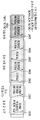
- FIG. 11 is a diagram for describing an example in which a SA resource pool and a resource pool of a subsequent data channel periodically appear according to the present invention.
- the SA resource pool described above appears before the resource pool of a series of D2D data channels, and the D2D RX UE first attempts to detect the SA, and only when the existence of the data that it needs to receive is found. Attempt to receive data from interworking data resource. Accordingly, as shown in FIG. 11, the resource pool of the SA resource pool and the following data channel may appear periodically.
- the period in which the SA resource pool appears is defined as an SA period.
- the HTX D2D UE can efficiently operate / manage not only its own transmission operation but also its reception operation at the same time.
- a UE transmitting information based on the present invention is defined as a “SIG TX UE”, while a UE receiving the information is defined as a “SIG RX UE”.
- FIG. 12 is a reference diagram for describing a link between a SIG TX UE and a SIG RX UE.
- the SIG TX UE and the SIG RX UE are different D2D UEs (eg, D2D UE # X, D2D UE # Y, D2D UE # Z of FIG. 9) that want to transmit a D2D signal to the HTX D2D UE and the HTX D2D UE, respectively. ) Can be interpreted.
- the link from the SIG TX UE to the SIG RX UE is defined as "Forward Link (FLink)", and the link from the SIG RX UE to the SIG TX UE is defined as "Reverse Link (RLink)”.
- FLink Forward Link
- RLink Reverse Link
- the information proposed in the present invention may be defined in the following contents / configurations as in the following schemes 2-1 to 2-9. There is.
- the SIG TX UE is an HTX D2D UE
- the SIG RX UE is another D2D UE that wants to transmit a D2D signal to the HTX D2D UE.
- the transmission operation of the HTX D2D UE not only transmits signals in the FLink direction (e.g., signals transmitted to the SIG RX UEs), but also signals (re) transmits (e.g., relays) that target the eNB (or a specific D2D UE). Operation).
- the SIG TX UE / HTX D2D UE may be configured to include the following control information related to the communication in the RLink direction and / or the FLink direction, respectively (predefined or A plurality of SA formats / modified SA formats / signaled) other signals / predefined signals may be configured to transmit (or once) simultaneously.
- the SIG TX UE can inform the SIG RX UE of resource location information to use when transmitting data in the RLink direction.
- the corresponding information transmitted according to the method 2-1 may include i) receivable resource location information (or expected to perform a receiving operation) or ii) not performing (or transmitting) from the perspective of the SIG TX UE. Resource location information, which is not expected to perform an operation).
- the information transmission operation according to the scheme 2-1 is performed in the FLink direction, but may also inform resource location information related to data transmission in the RLink direction.
- the corresponding information according to the method 2-1 may inform the SIG RX UE only an index of a time resource (eg, a T-RPT (Time Resource Pattern or Time Resource Pattern of Transmission)) for the SIG TX UE to perform a reception operation.
- the SIG TX UE may inform the SIG RX UE only of an index (eg, T-RPT) of a time resource for which the SIG TX UE will not perform a transmission operation.
- the SIG TX UE can inform the SIG RX UE of resource location information to be used when performing a transmission operation.
- the corresponding information according to the scheme 2-2 may include i) resource location information that is expected to perform a transmission operation (or perform a transmission operation) or ii) an RLink related reception operation in view of the SIG TX UE. Represents resource location information (or expected to not perform RLink related reception operation).
- the corresponding information according to the method 2-2 may inform the SIG RX UE only of an index (eg, T-RPT) of a time resource for performing (or expected to perform) the SIG TX UE.
- an index eg, T-RPT
- the SIG TX UE uses the remaining time resources except the time resources for which the SIG TX UE performs the transmission operation when the D2D data is transmitted to the SIG TX UE. Operate to receive data.
- the D2D data transmission in the corresponding resource may be omitted, which means that the SIG TA UE may be configured on the resource. Since the reception operation will not be performed, it is to reduce the interference by unnecessary transmission.
- schemes 2-1 and 2-2 of the present invention may be transmitted / received (or exchanged) in the form of a signal to which schemes 2-3 to 2-5 described below are applied.
- the field / content configuration based on the method 2-3 to the method 2-5 may be extended to each other.
- Scheme 2-3 In accordance with Scheme 2-3, signals can be transmitted / received through the use of existing SA formats or variations thereof.
- Example 2-3-1 An existing SA format or variant thereof that transmits information based on this scheme 2-3 may have a feature that is transmitted independently without subsequent transmission data (ie, SA Only Transmission).
- Example 2-3-2 In Method 2-1 and Method 2-2, when the SIG TX UE informs the SIG RX UE only of an index (eg, T-RPT) of a time resource for performing a reception / transmission operation, A field / bit indicating the frequency resource location information on the existing SA format may not be needed. These extra fields / bits may be set (i.e., may increase the number of T-RPT candidates) to be used (in combination) to inform the time resource location where the SIG TX UE will perform the receive / transmit operation. .
- an index eg, T-RPT
- a field / bit indicating the frequency resource location information on the existing SA format may not be needed.
- These extra fields / bits may be set (i.e., may increase the number of T-RPT candidates) to be used (in combination) to inform the time resource location where the SIG TX UE will perform the receive / transmit operation. .
- Example 2-3-3 Through one SA format transmission (e.g., in a unicast operation), resource position information for the SIG TX UE to perform a transmission operation and resource position information to be used when transmitting data in the RLink direction You can tell at the same time.
- an odd-numbered resource is used for transmission operation of the SIG TX UE during the T-RPT designated by the SA through a predefined rule / signaling, and the even-numbered resource is used in the RLink direction of the SIG TX UE. It can be used for data reception purposes.
- Example 2-3-4 Time resource location information and / or on a corresponding SA format (ie, existing SA format + additional field) by defining additional fields (eg, 1-bit tag fields) on an existing SA format
- the frequency resource location information may be distinguished from whether i) resource location information to be used for data transmission in the RLink direction or ii) resource location information for the SIG TX UE to perform a transmission operation.
- An existing SA format is i) a dedicated form of specifying a specific resource and notifying a specific UE, or ii) unspecifying UEs (or UE groups) for information about the RLink / FLink resource pool.
- Broadcasted form e.g., a SIG TX UE can signal (e.g., T-RPT) a subset of a predefined D2D resource pool or signaled from an eNB (or a specific D2D UE) to its receivable resource pool. May be present).
- Scheme 2-4 According to Scheme 2-4, a signal can be transmitted / received using a D2D data channel.
- the SIG TX UE may inform the SIB RX UE of resource location information for which it will perform a reception / transmission operation through a D2D data channel (predefined or signaled, not in SA format).
- the D2D data channel for the purpose is i) Dedicated form to designate a specific resource to inform a specific UE, or ii) Broadcasted form to inform information about the RLink / FLink resource pool to unspecified UEs (or UE group) It may be.
- a SIG TX UE broadcasts a subset of a resource pool associated with a predefined D2D signal transmission / reception or broadcasts from an eNB (or a specific D2D UE) to its receivable resource pool.
- Cast signaling eg, scheme 2-1
- a SIG TX UE may be broadcast signaled from an eNB (or a specific D2D UE) or broadcast a subset of a predefined D2D signal transmission / reception related resource pool to a resource pool where its transmission operation is performed (eg, Alternatively, option 2-2) may be used.
- such operations may be performed through a predefined or signaled broadcast data channel.
- Example 2-4-2 A D2D data channel for a given purpose may have a feature (ie, D2D Data Channel Only Transmission) transmitted independently (without a preceding SA format transmission).
- the resource to which the D2D data channel for the purpose is transmitted is i) defined or signaled in advance, or ii) a new UE identifier (ID) previously defined or signaled as an input variable. It can be determined by a function having a function, or iii) a function having a physical layer identifier / cell identifier generated from a UE identifier as an input variable.
- Scheme 2-5 According to Scheme 2-5, a signal can be transmitted / received using a newly defined channel (hereinafter, “Special Channel (SChannel)”).
- SChannel a newly defined channel
- Example 2-5-1 In order to transmit information according to the present scheme 2-5, an SChannel may be introduced.
- the SChannel may be defined as a field / content configuration similar to the existing SA format of the above-described scheme 2-3 or its modification, or similar to the D2D data channel of the above-described scheme 2-4.
- the resource to which the SChannel according to the present scheme 2-5 is transmitted is i) a function having a new UE identifier (ID) previously defined or signaled, or ii) previously defined or signaled, or iii). It may be determined by a function having a physical layer identifier / cell identifier generated from the UE identifier as an input variable.
- ID new UE identifier
- cell identifier generated from the UE identifier
- the signal (eg, scheme 2-3, scheme 2-4, scheme 2-5) through which the above-described present invention-based information (example, scheme 2-1, scheme 2-2) is transmitted is described in scheme 2 below.
- 6 to 2-9 FLink related
- Scheme 2-6 The signal on which the present invention-based information is transmitted is different from that of the existing SA format related to FLink, i) CRC masking based on a new UE identifier or a physical layer identifier value generated from a predefined UE identifier or UE identifier. Or ii) scrambling / base sequence group hopping / sequence hopping based on a cell identifier value previously signaled or defined.
- Scheme 2-7 On the signal in which the present invention-based information is transmitted, unlike the configuration of the existing SA format related to FLink, the field related to the identifier information transmission of the SIG TX UE is i) together with the field related to the identifier information transmission of the SIG RX UE, or ii) Can be defined without a field for transmitting identifier information of the SIG RX UE.
- an indicator field may be defined to indicate a signal on which information based on this scheme 2-7 is transmitted to distinguish it from an existing SA format (and / or a D2D data channel).
- Scheme 2-8 Resource pool of a signal to which the present invention-based information is transmitted (hereinafter, “New Signal Resource Pool (NSIG RP)”) and resource pool of an existing signal (eg, existing SA format and / or D2D data channel) (Hereinafter, “Original Signal Resource Pool (OSIG RP)”) may be set independently (eg, at least in part (ie, part or all) differently).
- the NSIG RP may be set to appear earlier (on the time domain) than the OSIG RP, or may be set to appear periodically based on periods independent of each other (predefined or signaled).
- FIG. 13 is a reference diagram for explaining a case in which NSIG RP is set to appear earlier in the time domain as compared to OSIG RP as described above in the method 2-8 of the present invention.
- another D2D UE i.e. SIG RX UE
- a D2D signal e.g., data transmission in the RLink direction
- the HTX D2D UE i.e., SIG TX UE
- the present invention 2-8 based information transmitted from the HTX D2D UE on the NSIG RP may be configured to perform discovery / blind detection on a signal transmitted.
- the other D2D UE uses a resource other than the resource used for transmission by the HTX D2D UE (or a resource where the HTX D2D UE performs a reception operation), and the D2D in the RLink direction.
- a signal transmission operation is performed, and an SA format including related information (ie, resource allocation information related to D2D signal transmission operation in the RLink direction) is transmitted on the OSIG RP.
- the other D2D UE can expect a successful reception of the signal (with high probability), and the half-duplex (HD) Problems caused by the characteristics can be solved.
- the D2D UE in order to perform a D2D signal transmission operation to the HTX D2D UE, only another D2D UE additionally performs discovery / blind detection on a signal on which the information 2-8 based on the present scheme transmitted from the HTX D2D UE on the NSIG RP is transmitted. Can be set.
- the D2D UE in order to perform a D2D signal transmission operation to a general D2D UE (ie, Non-HTX D2D UE), the D2D UE may be configured to perform discovery / blind detection for the existing SA format only in the OSIG RP.
- the NSIG RP of the signal on which the present invention-based information is transmitted and the OSIG RP of the existing signal may be defined as the same resource pool.
- a signal to which the present invention-based information is transmitted and an existing signal may be multiplexed and transmitted in the same resource pool.
- Embodiments / descriptions / rules of the present invention described above may be interpreted / applied / implemented as one independent embodiment each.
- the above-described embodiments of the present invention may be implemented independently, but may be implemented in a combination / merge form of some embodiments.
- V2D (Device-To-Device) communication may be interpreted as “V2X (Vehicle-To-X) communication".
- X may be interpreted as a vehicle (V2V) or a person (V2P) or an infrastructure (V2I).
- the above-described embodiments of the present invention may be set to be applied only in the case of Mode 1 (or Mode 2) D2D communication operation.
- the above-described embodiments of the present invention may be set to be limitedly applied only in the case of a D2D communication operation and / or a D2D discovery operation.
- the above-described embodiments of the present invention may be set to be limited to V2X communication only.
- the above-described embodiments of the present invention inform the SIG TX UE of various control information related to data communication that the SIG RX UE transmits to another D2D UE (rather than data transmission to the SIG TX UE). It can also be applied to give.
- the D2D TX UE when the D2D communication is extended to the unicast form, the D2D TX UE (or SIG TX UE) is not only control information for the transmission data but also various types of control information D2D RX UE ( Or SIG RX UE).
- the embodiments of the present invention described above when the D2D communication is performed in the unlicensed band, the result of the SIG RX UE performing the Carrier Sensing of the unlicensed band to the SIG TX UE (e.g., BUSY / IDLE) and / or FLink It may also be extended when notifying the SIG TX UE of resource allocation / control information related to data transmission in a direction.
- the SIG RX UE perform the Carrier Sensing of the unlicensed band to the SIG TX UE (e.g., BUSY / IDLE) and / or FLink It may also be extended when notifying the SIG TX UE of resource allocation / control information related to data transmission in a direction.
- the above embodiments are transmitted in the FLink direction, but may be used to inform the SIG RX UE of various control information related to signal transmission in the RLink direction and / or various control information related to signal transmission in the FLink direction. , And specific examples thereof are the same as the use # 1 to use # 7. Furthermore, on the signal according to the present invention, a field indicating the use of the signal (eg, “(Application # 1) to (Application # 7) or (Method 2-1) to (Method 2-2)”) is defined or It may also include an indicator indicating the purpose of the signal.
- Use # 1 it is possible to transmit an indicator for triggering transmission of communication-related timing (TA) information in the RLink direction.
- the indicator related to the use # 1 may be applied for the purpose of (re) transmitting TA information related to D2D signal reception in the RLink direction by the SIG TX UE to the SIG RX UE.
- the indicator transmission operation may determine that the RLink related time synchronization is incorrect (from the SIG TX UE's point of view), so that the SIG RX UE may (re) adjust / update the RLink related (current) TA information. It can also be interpreted as.
- TPC Transmission Power Command
- the information related to the use # 2 may be transmitted through a TPC field defined on the signal based on the present invention, and the TPC field may correspond to a (current) D2D signal transmission power in a RLink direction that is previously set or signaled. It can tell you the offset value.
- this operation may be operated by the Absolute Power Control method (or Accumulated Power Control method).
- the corresponding TPC field may be interpreted to indicate an increase / decrease in the (current) D2D signal transmission power in a preset or signaled RLink direction.
- a plurality of TPC fields may be defined (eg, similar to DCI format 3 / 3A) on a signal according to the present invention.
- one TPC field may be linked with a specific RLink signaled or signaled in advance, and may transmit control information on the (current) D2D signal transmission power in the specific RLink direction.
- a signal based on the present invention may transmit a plurality of RLinks related power control information.
- Use # 3 it is possible to transmit communication-related TA information in the FLink direction.
- the TA information may be used by the SIG TX UE to inform the SIG RX UE of the TA information related to receiving the D2D signal in the FLink direction.
- TA information transmission according to use # 3 may be implemented as in the examples of # 3-1 to # 3-3 below.
- such a signal can be interpreted as (SA TX UE) to update the TA information (or SA to be applied in the FLink) related to receiving the D2D signal in the FLink direction.
- the examples of # 3-1 to # 3-3 may be extended when TA information related to D2D signal reception in the RLink direction is transmitted (for example, use # 1).
- Example # 3-1 The SIG TX UE sends a signal to the SIG RX UE several times (as many as a predefined or signaled signal) based on a proposed scheme in which TA information related fields (eg, T bits) are defined.
- TA information related to D2D signal reception in the FLink direction can be set relatively accurately (that is, interpreted as a kind of gradual adjustment).
- a signal based on the present invention in which the TA field is defined is transmitted N times (eg, “first signal transmission including TA1 information, second signal transmission including TA2 information, ..., TAN information is included) Transmitted Nth signal ”)
- the SIG RX UE receiving the N signals is finally“ TA1 + TA2 +... + TAN ”value is assumed to receive D2D signal in FLink direction.
- N times of SA format transmission may be defined or configured to be performed on one (same) resource pool or to be performed on a plurality of resource pools.
- the latter i.e. when performed over multiple resource pools
- SA RX UE is a D2D signal (e.g. discovery message, D2D Data channel, SA, etc.) can alleviate the failure to receive the corresponding (n part or all) of the SA format transmission.
- Example # 3-2 On the present invention-based signal described in Example # 3-1, a Granularity Indicator Field (GIF) related to TA information may be defined.
- the GIF may indicate whether the TA value indicated by the TA field is incremented / decreased with an interval.
- the SIG RX UE finally sends a "predefined or signaled reference value (eg 0) + 2 * K value" to the FLink direction. It is assumed for the D2D signal reception.
- the value indicated by the specific bit value of the GIF may be defined to be i) signaled from the eNB, ii) fixed to a specific value on the spec, or iii) linked to a resource pool related to D2D signal transmission / reception. Can also be.
- the GIF may exhibit a different value at least in part (ie, part or all).
- the preceding M times may indicate a relatively large value of the GIF (ie, Coarse TA Adjustment), and the following (NM) times may exhibit a relatively small value (ie, Fine TA Adjustment).
- This method is intended to set a relatively accurate TA value within a limited N signal transmissions.
- the TA field size may be differently defined for each signal transmission based on the present invention without defining / implementing a GIF, so that a relatively accurate TA value may be set. Specifically, during N signal transmissions, the TA field size of the preceding M times may be set relatively small, and the following (NM) times may be set relatively large.
- a small TA field size (ie, S bits) is a partition of a predefined range of TA values (ie “TA_MIN to TA_MAX”) into a relatively small number (eg, 2 S ) (ie, Coarse TA adjustment, whereas a large TA field size (i.e., L bits (L> S)) is a split of a predefined range of TA values into a relatively large number (e.g. 2 L ) (i.e. , Fine TA Adjustment).
- the same TA Granularity value predefined or signaled
- at least some (ie, some or all) of TA fields may be defined differently (for still). have.
- a TA granularity value different from at least some of the predefined or signaled signals may be set for each order of signal transmission based on the present invention without further defining / implementing a GIF and changing a TA field size. .
- Example # 3-3 On the present invention-based signal described in Example # 3-1, an Order Indication Field (OIF) indicating that the signal transmitted at a particular point in time is (of N predefined times or signaled). May be defined. For example, if the SIG RX UE finds that at least one of the N signal receptions has failed through the OIF, i) inform the SIG TX UE of this situation via a predefined signal (e.g., the corresponding feedback signal).
- OIF Order Indication Field
- the SIG TX UE which has received the SIG RX UE may retransmit the TA information related signal that failed to be received by the SIG RX UE), or ii) apply a specific final TA value previously defined or signaled, or iii) the TA information related to the failed signal reception. It may also be set to assume that only a predefined value that is predefined or signaled.
- the number of signal transmissions (during predefined N or pre-signed N times) of a signal transmitted at a specific time without implementing OIF is used at the time the signal is transmitted and / or the frequency resource location or the signal transmission / decoding. It may be set to be identified by the resource type (eg, CS, OCC, Antenna Port, etc.) of the reference signal (eg, DM-RS).
- the resource type eg, CS, OCC, Antenna Port, etc.
- the reference signal eg, DM-RS
- power control information related to D2D signal transmission in the FLink direction can be transmitted.
- the information may be transmitted through a TPC field defined on a signal based on the present invention, and the TPC field indicates an offset value for the (current) D2D signal transmission power in a pre-configured or signaled FLink direction. May be used for the purpose.
- this operation may be operated by the Absolute Power Control method (or Accumulated Power Control method).
- TPC fields may be defined (eg, similar to DCI format 3 / 3A) on one signal.
- one TPC field may be linked with a specific FLink defined or signaled in advance, and may transmit control information about (current) D2D signal transmission power in the specific FLink direction.
- one signal may transmit power control information related to a plurality of FLinks.
- Wake UP indication information for receiving a D2D signal in the FLink direction can be transmitted.
- the indication information according to use # 5 may be used for instructing Wake UP to enable the SIG TX UE to receive D2D signal in the FLink direction to its target UE (or SIG RX UE), which is a kind of D2D communication. It can be interpreted as a related paging application.
- the method may be extended to use for indicating Wake UP to enable the reception of the D2D signal in the RLink direction (to the SIG RX UE to its target UE (or SIG TX UE)).
- an indicator for triggering a CSI measurement operation and / or a CSI reporting operation can be transmitted.
- the usage # 6 related indicator may be used by the SIG TX UE to instruct its target UE (or SIG RX UE) to instruct CSI measurement operation and / or CSI reporting operation for a link between the UEs.
- the corresponding CSI measurement operation may be set to be performed based on, for example, the DM-RS used for signal transmission / decoding based on the present invention.
- the measured CSI may be transmitted through RLink using RPT (Time Resource Pattern or Resource Pattern of Transmission) indicated by the corresponding signal.
- this method can be extended to the RLink direction (eg, the SIG RX UE transmits to its target UE (or SIG TX UE)).
- Use # 7 it may be set to inform some information (eg, DM-RS CS, NDI, MCS / RV, FH, HARQ ID, PMI, etc.) indicated by the PDCCH. There is also.
- some information eg, DM-RS CS, NDI, MCS / RV, FH, HARQ ID, PMI, etc.
- Embodiments / descriptions / rules of the present invention described above may be interpreted / applied / implemented as one independent embodiment each.
- the above-described embodiments of the present invention may be implemented independently, but may be implemented in a combination / merge form of some embodiments.
- the above-described embodiment of the present invention (e.g., SA only transmission type), i) when D2D communication is performed in an unlicensed band, the D2D RX UE senses an unlicensed band to a D2D TX UE. Extension can also be applied to inform the result of execution (eg, BUSY / IDLE) and / or ii) resource allocation / control information related to data transmission in the FLink direction.
- the result of execution eg, BUSY / IDLE
- resource allocation / control information related to data transmission in the FLink direction e.g., SA only transmission type
- HTX D2D UE Heavy Transmission D2D UE, for example, D2D Relay UE (D2D RUE), D2D Group Owner UE (D2D GOUE), Independent Synchronization Source (ISS), etc.
- D2D RUE D2D Relay UE
- D2D GOUE D2D Group Owner UE
- ISS Independent Synchronization Source
- FIG. 14 illustrates a base station and a terminal that can be applied to an embodiment of the present invention.
- a relay When a relay is included in the wireless communication system, communication is performed between the base station and the relay in the backhaul link, and communication is performed between the relay and the terminal in the access link. Therefore, the base station or the terminal illustrated in the figure may be replaced with a relay according to the situation.
- a wireless communication system includes a base station (BS) 110 and a terminal (UE) 120.
- Base station 110 includes a processor 112, a memory 114, and a radio frequency (RF) unit 116.
- the processor 112 may be configured to implement the procedures and / or methods proposed in the present invention.
- the memory 114 is connected to the processor 112 and stores various information related to the operation of the processor 112.
- the RF unit 116 is connected with the processor 112 and transmits and / or receives a radio signal.
- the terminal 120 includes a processor 122, a memory 124, and an RF unit 126.
- the processor 122 may be configured to implement the procedures and / or methods proposed by the present invention.
- the memory 124 is connected with the processor 122 and stores various information related to the operation of the processor 122.
- the RF unit 126 is connected with the processor 122 and transmits and / or receives a radio signal.
- the base station 110 and / or the terminal 120 may have a single antenna or multiple antennas.
- each component or feature is to be considered optional unless stated otherwise.
- Each component or feature may be embodied in a form that is not combined with other components or features. It is also possible to combine some of the components and / or features to form an embodiment of the invention.
- the order of the operations described in the embodiments of the present invention may be changed. Some components or features of one embodiment may be included in another embodiment or may be replaced with corresponding components or features of another embodiment. It is obvious that the claims may be combined to form an embodiment by combining claims that do not have an explicit citation relationship in the claims or as new claims by post-application correction.
- Certain operations described in this document as being performed by a base station may in some cases be performed by an upper node thereof. That is, it is obvious that various operations performed for communication with the terminal in a network including a plurality of network nodes including a base station may be performed by the base station or other network nodes other than the base station.
- a base station may be replaced by terms such as a fixed station, a Node B, an eNodeB (eNB), an access point, and the like.
- Embodiments according to the present invention may be implemented by various means, for example, hardware, firmware, software, or a combination thereof.
- an embodiment of the present invention may include one or more application specific integrated circuits (ASICs), digital signal processors (DSPs), digital signal processing devices (DSPDs), programmable logic devices (PLDs), FPGAs ( field programmable gate arrays), processors, controllers, microcontrollers, microprocessors, and the like.
- ASICs application specific integrated circuits
- DSPs digital signal processors
- DSPDs digital signal processing devices
- PLDs programmable logic devices
- FPGAs field programmable gate arrays
- processors controllers, microcontrollers, microprocessors, and the like.
- an embodiment of the present invention may be implemented in the form of a module, procedure, function, etc. that performs the functions or operations described above.
- the software code may be stored in a memory unit and driven by a processor.
- the memory unit may be located inside or outside the processor, and may exchange data with the processor by various known means.
Landscapes
- Engineering & Computer Science (AREA)
- Computer Networks & Wireless Communication (AREA)
- Signal Processing (AREA)
- Mobile Radio Communication Systems (AREA)
Abstract
Provided is a method for transmitting resource information for device-to-device (D2D) communication of a D2D transmission terminal in a wireless communication system, the method being characterized by comprising the steps of: receiving a resource pool configuration for D2D communication; and transmitting, to a D2D reception terminal, resource information therefor indicating the resource for a first D2D signal transmission to the D2D transmission terminal.
Description
본 발명은 무선 통신 시스템에 관한 것으로서, 보다 상세하게는, 무선 통신 시스템에서 D2D(Device-to-Device) 통신을 위한 자원 정보 송신 방법 및 이를 위한 장치에 관한 것이다.The present invention relates to a wireless communication system, and more particularly, to a method and apparatus for transmitting resource information for device-to-device (D2D) communication in a wireless communication system.
본 발명이 적용될 수 있는 무선 통신 시스템의 일례로서 3GPP LTE (3rd Generation Partnership Project Long Term Evolution, 이하 "LTE"라 함) 통신 시스템에 대해 개략적으로 설명한다.As an example of a wireless communication system to which the present invention may be applied, a 3GPP LTE (3rd Generation Partnership Project Long Term Evolution (LTE)) communication system will be described in brief.
도 1은 무선 통신 시스템의 일례로서 E-UMTS 망구조를 개략적으로 도시한 도면이다. E-UMTS(Evolved Universal Mobile Telecommunications System) 시스템은 기존 UMTS(Universal Mobile Telecommunications System)에서 진화한 시스템으로서, 현재 3GPP에서 기초적인 표준화 작업을 진행하고 있다. 일반적으로 E-UMTS는 LTE(Long Term Evolution) 시스템이라고 할 수도 있다. UMTS 및 E-UMTS의 기술 규격(technical specification)의 상세한 내용은 각각 "3rd Generation Partnership Project; Technical Specification Group Radio Access Network"의 Release 7과 Release 8을 참조할 수 있다.1 is a diagram schematically illustrating an E-UMTS network structure as an example of a wireless communication system. The Evolved Universal Mobile Telecommunications System (E-UMTS) system is an evolution from the existing Universal Mobile Telecommunications System (UMTS), and is currently undergoing basic standardization in 3GPP. In general, the E-UMTS may be referred to as a Long Term Evolution (LTE) system. For details of technical specifications of UMTS and E-UMTS, refer to Release 7 and Release 8 of the "3rd Generation Partnership Project; Technical Specification Group Radio Access Network", respectively.
도 1을 참조하면, E-UMTS는 단말(User Equipment, UE)과 기지국(eNode B, eNB, 네트워크(E-UTRAN)의 종단에 위치하여 외부 네트워크와 연결되는 접속 게이트웨이(Access Gateway, AG)를 포함한다. 기지국은 브로드캐스트 서비스, 멀티캐스트 서비스 및/또는 유니캐스트 서비스를 위해 다중 데이터 스트림을 동시에 전송할 수 있다. Referring to FIG. 1, an E-UMTS is located at an end of a user equipment (UE) and a base station (eNode B, eNB, network (E-UTRAN)) and connects an access gateway (AG) connected to an external network. The base station may transmit multiple data streams simultaneously for broadcast service, multicast service and / or unicast service.
한 기지국에는 하나 이상의 셀이 존재한다. 셀은 1.25, 2.5, 5, 10, 15, 20Mhz 등의 대역폭 중 하나로 설정돼 여러 단말에게 하향 또는 상향 전송 서비스를 제공한다. 서로 다른 셀은 서로 다른 대역폭을 제공하도록 설정될 수 있다. 기지국은 다수의 단말에 대한 데이터 송수신을 제어한다. 하향 링크(Downlink, DL) 데이터에 대해 기지국은 하향 링크 스케줄링 정보를 전송하여 해당 단말에게 데이터가 전송될 시간/주파수 영역, 부호화, 데이터 크기, HARQ(Hybrid Automatic Repeat and reQuest) 관련 정보 등을 알려준다. 또한, 상향 링크(Uplink, UL) 데이터에 대해 기지국은 상향 링크 스케줄링 정보를 해당 단말에게 전송하여 해당 단말이 사용할 수 있는 시간/주파수 영역, 부호화, 데이터 크기, HARQ 관련 정보 등을 알려준다. 기지국간에는 사용자 트래픽 또는 제어 트래픽 전송을 위한 인터페이스가 사용될 수 있다. 핵심망(Core Network, CN)은 AG와 단말의 사용자 등록 등을 위한 네트워크 노드 등으로 구성될 수 있다. AG는 복수의 셀들로 구성되는 TA(Tracking Area) 단위로 단말의 이동성을 관리한다.One or more cells exist in one base station. The cell is set to one of bandwidths such as 1.25, 2.5, 5, 10, 15, and 20Mhz to provide downlink or uplink transmission services to multiple terminals. Different cells may be configured to provide different bandwidths. The base station controls data transmission and reception for a plurality of terminals. For downlink (DL) data, the base station transmits downlink scheduling information to inform the corresponding UE of time / frequency domain, encoding, data size, and HARQ (Hybrid Automatic Repeat and reQuest) related information. In addition, the base station transmits uplink scheduling information to the terminal for uplink (UL) data, and informs the time / frequency domain, encoding, data size, HARQ related information, etc. that the terminal can use. An interface for transmitting user traffic or control traffic may be used between base stations. The core network (Core Network, CN) may be composed of a network node for the user registration of the AG and the terminal. The AG manages the mobility of the UE in units of a tracking area (TA) composed of a plurality of cells.
무선 통신 기술은 WCDMA를 기반으로 LTE까지 개발되어 왔지만, 사용자와 사업자의 요구와 기대는 지속적으로 증가하고 있다. 또한, 다른 무선 접속 기술이 계속 개발되고 있으므로 향후 경쟁력을 가지기 위해서는 새로운 기술 진화가 요구된다. 비트당 비용 감소, 서비스 가용성 증대, 융통성 있는 주파수 밴드의 사용, 단순구조와 개방형 인터페이스, 단말의 적절한 파워 소모 등이 요구된다.Wireless communication technology has been developed to LTE based on WCDMA, but the demands and expectations of users and operators are continuously increasing. In addition, as other radio access technologies continue to be developed, new technological evolution is required to be competitive in the future. Reduced cost per bit, increased service availability, the use of flexible frequency bands, simple structure and open interface, and adequate power consumption of the terminal are required.
단말은 기지국의 무선 통신 시스템의 효율적인 운용을 보조하기 위하여, 현재 채널의 상태 정보를 기지국에게 주기적 및/또는 비주기적으로 보고한다. 이렇게 보고되는 채널의 상태 정보는 다양한 상황을 고려하여 계산된 결과들을 포함할 수 있기 때문에, 보다 더 효율적인 보고 방법이 요구되고 있는 실정이다.The terminal reports the current channel state information periodically and / or aperiodically to the base station in order to assist efficient operation of the base station wireless communication system. Since the state information of the reported channel may include the results calculated in consideration of various situations, a more efficient reporting method is required.
상술한 바와 같은 논의를 바탕으로 이하에서는 무선 통신 시스템에서 D2D(Device-to-Device) 통신을 위한 자원 정보 송신 방법 및 이를 위한 장치를 제안하고자 한다.Based on the discussion as described above, the present invention proposes a method and apparatus for transmitting resource information for device-to-device (D2D) communication in a wireless communication system.
본 발명에서 이루고자 하는 기술적 과제들은 상기 기술적 과제로 제한되지 않으며, 언급하지 않은 또 다른 기술적 과제들은 아래의 기재로부터 본 발명이 속하는 기술분야에서 통상의 지식을 가진 자에게 명확하게 이해될 수 있을 것이다.Technical problems to be achieved in the present invention are not limited to the above technical problems, and other technical problems that are not mentioned will be clearly understood by those skilled in the art from the following description.
상술한 문제점을 해결하기 위한 본 발명의 일 양상인, 무선 통신 시스템에서 D2D 송신 단말의 D2D(Device-to-Device) 통신을 위한 자원 정보를 송신하는 방법은, D2D 통신을 위한 자원 풀(resource pool) 설정을 수신하는 단계; 및 D2D 수신 단말의 상기 D2D 송신 단말로의 제 1 D2D 신호 송신을 위한 자원을 지시하는 자원 정보를 상기 D2D 수신 단말로 송신하는 단계를 포함할 수 있다.In one aspect of the present invention for solving the above problems, a method for transmitting resource information for device-to-device (D2D) communication of a D2D transmitting terminal in a wireless communication system, a resource pool for D2D communication (resource pool) ) Receiving a setting; And transmitting, to the D2D receiving terminal, resource information indicating a resource for transmitting a first D2D signal from the D2D receiving terminal to the D2D transmitting terminal.
나아가, 상기 자원 정보는, 상기 D2D 송신 단말이 상기 1 D2D 신호 송신을 수행할 경우, 상기 D2D 송신 단말이 수신 가능한 무선 자원을 지시하는 것을 특징으로 할 수 있다.Further, the resource information may be characterized in that when the D2D transmitting terminal performs the 1 D2D signal transmission, the D2D transmitting terminal indicates a radio resource that can be received.
나아가, 상기 자원 정보는, 상기 제 1 D2D 신호 송신을 위한 제 1 무선 자원을 지시하며, 상기 제 1 무선 자원은, 제 2 무선 자원을 제외한 자원 풀 상에 설정되고, 상기 제 2 무선 자원은, 상기 D2D 송신 단말의 상기 D2D 수신 단말로의 제 2 D2D 신호 송신을 위하여 사용되는 무선 자원인 것을 특징으로 할 수 있다.Further, the resource information indicates a first radio resource for transmitting the first D2D signal, the first radio resource is set on a resource pool excluding a second radio resource, and the second radio resource is The D2D transmitting terminal may be a radio resource used for transmitting a second D2D signal to the D2D receiving terminal.
나아가, 상기 자원 정보는, 스케줄링 할당(Scheduling Assignment)을 위한 자원 풀 상에 매핑되는 것을 특징으로 할 수 있다.Further, the resource information may be mapped onto a resource pool for scheduling assignment.
나아가, 상기 자원 정보는, D2D 데이터를 위한 자원 풀 상에 매핑되는 것을 특징으로 할 수 있다.Furthermore, the resource information may be mapped onto a resource pool for D2D data.
나아가, 상기 자원 정보는, 미리 정의된 채널을 이용하여 전송되며, 상기 자원은, D2D 단말 식별자(D2D UE ID)에 기반하여 결정되는 것을 특징으로 할 수 있다.Furthermore, the resource information may be transmitted using a predefined channel, and the resource may be determined based on a D2D terminal identifier (D2D UE ID).
나아가, 상기 자원 정보는, D2D 단말 식별자에 기반하여 CRC(Cyclic Redundancy Check) 마스킹되도록 설정된 것을 특징으로 할 수 있다.Furthermore, the resource information may be configured to be masked by a cyclic redundancy check (CRC) based on the D2D UE identifier.
나아가, 상기 자원 정보는, 상기 D2D 송신 단말의 식별자 정보 연관 필드를 포함하도록 설정된 것을 특징으로 할 수있다.Furthermore, the resource information may be configured to include an identifier information association field of the D2D transmitting terminal.
나아가, 상기 자원 정보는, 상기 제 1 D2D 신호 송신 혹은 상기 제 2 D2D 신호 송신 중 적어도 하나를 위한 제어 정보와 함께 전송되도록 설정된 것을 특징으로 할 수 있다.Furthermore, the resource information may be configured to be transmitted together with control information for at least one of the first D2D signal transmission or the second D2D signal transmission.
상술한 문제점을 해결하기 위한 본 발명의 다른 양상인, 무선 통신 시스템에서 D2D(Device-to-Device) 통신을 위한 자원 정보를 송신하는 D2D 송신 단말은, 무선 주파수 유닛(Radio Frequency Unit); 및 프로세서(Processor)를 포함하며, 상기 프로세서는, D2D 통신을 위한 자원 풀(resource pool) 설정을 수신하고, D2D 수신 단말의 상기 D2D 송신 단말로의 제 1 D2D 신호 송신을 위한 자원을 지시하는 자원 정보를 상기 D2D 수신 단말로 송신하도록 구성될 수 있다.In another aspect of the present invention, a D2D transmitting terminal for transmitting resource information for device-to-device (D2D) communication in a wireless communication system includes: a radio frequency unit; And a processor, wherein the processor receives a resource pool setting for D2D communication and indicates a resource for transmitting a resource for transmitting a first D2D signal from the D2D receiving terminal to the D2D transmitting terminal It may be configured to transmit information to the D2D receiving terminal.
본 발명의 실시예에 따르면 무선 통신 시스템에서 D2D 통신을 위한 자원 정보가 효율적으로 송수신될 수 있다.According to an embodiment of the present invention, resource information for D2D communication may be efficiently transmitted and received in a wireless communication system.
본 발명에서 얻은 수 있는 효과는 이상에서 언급한 효과들로 제한되지 않으며, 언급하지 않은 또 다른 효과들은 아래의 기재로부터 본 발명이 속하는 기술분야에서 통상의 지식을 가진 자에게 명확하게 이해될 수 있을 것이다.Effects obtained in the present invention are not limited to the above-mentioned effects, and other effects not mentioned above may be clearly understood by those skilled in the art from the following description. will be.
본 발명에 관한 이해를 돕기 위해 상세한 설명의 일부로 포함되는, 첨부 도면은 본 발명에 대한 실시예를 제공하고, 상세한 설명과 함께 본 발명의 기술적 사상을 설명한다.BRIEF DESCRIPTION OF THE DRAWINGS The accompanying drawings, which are included as part of the detailed description in order to provide a thorough understanding of the present invention, provide an embodiment of the present invention and together with the description, illustrate the technical idea of the present invention.
도 1은 무선 통신 시스템의 일례로서 E-UMTS 망구조를 개략적으로 예시한다.1 schematically illustrates an E-UMTS network structure as an example of a wireless communication system.
도 2는 3GPP 무선 접속망 규격을 기반으로 한 단말과 E-UTRAN 사이의 무선 인터페이스 프로토콜(Radio Interface Protocol)의 제어평면(Control Plane) 및 사용자평면(User Plane) 구조를 예시한다.FIG. 2 illustrates a structure of a control plane and a user plane of a radio interface protocol between a terminal and an E-UTRAN based on the 3GPP radio access network standard.
도 3은 3GPP 시스템에 이용되는 물리 채널들 및 이들을 이용한 일반적인 신호 전송 방법을 예시한다.3 illustrates physical channels used in a 3GPP system and a general signal transmission method using the same.
도 4는 LTE 시스템에서 사용되는 무선 프레임의 구조를 예시한다.4 illustrates a structure of a radio frame used in an LTE system.
도 5는 하향링크 슬롯에 대한 자원 그리드(resource grid)를 예시한다.5 illustrates a resource grid for a downlink slot.
도 6은 LTE 시스템에서 사용되는 하향링크 무선 프레임의 구조를 예시한다.6 illustrates a structure of a downlink radio frame used in an LTE system.
도 7은 LTE 시스템에서 사용되는 상향링크 서브프레임의 구조를 예시한다.7 illustrates a structure of an uplink subframe used in an LTE system.
도 8은 D2D(UE-to-UE Communication) 통신을 설명하기 위한 참고도이다.8 is a reference diagram for explaining UE-to-UE communication (D2D) communication.
도 9는 본 발명의 일 실시예에 따라, HTX D2D UE인 D2D RUE가 수행하는 통신을 나타낸다.9 illustrates communication performed by a D2D RUE, which is an HTX D2D UE, according to an embodiment of the present invention.
도 10 은 D2D 통신을 위한 자원 유닛(RU)의 구성을 나타낸다.10 shows a configuration of a resource unit (RU) for D2D communication.
도 11은 본 발명에 따른 스케줄링 할당(SA) 자원 풀과 후행하는 데이터 채널의 자원 풀이 주기적으로 나타나는 경우를 나타낸다.11 illustrates a case in which a scheduling allocation (SA) resource pool and a resource pool of a subsequent data channel periodically appear according to the present invention.
도 12는, 본 발명 상에서의, SIG TX UE와 SIG RX UE의 연결(link)을 나타내다.12 shows a link between a SIG TX UE and a SIG RX UE in the present invention.
도 13은, 본 발명의 일 실시예에 따라 NSIG RP가 OSIG RP에 비해 시간 영역 상에서 선행하여 나타나는 경우를 설명하기 위한 참고도이다.FIG. 13 is a reference diagram for explaining a case in which NSIG RP appears earlier in the time domain than in OSIG RP according to one embodiment of the present invention.
도 14는 본 발명의 일 실시예에 적용될 수 있는 기지국 및 단말을 나타낸다.14 illustrates a base station and a terminal that can be applied to an embodiment of the present invention.
이하의 기술은 CDMA(code division multiple access), FDMA(frequency division multiple access), TDMA(time division multiple access), OFDMA(orthogonal frequency division multiple access), SC-FDMA(single carrier frequency division multiple access) 등과 같은 다양한 무선 접속 시스템에 사용될 수 있다. CDMA는 UTRA(Universal Terrestrial Radio Access)나 CDMA2000과같은 무선 기술(radio technology)로 구현될 수 있다. TDMA는 GSM(Global System for Mobile communications)/GPRS(General Packet Radio Service)/EDGE(Enhanced Data Rates for GSM Evolution)와 같은 무선 기술로 구현될 수 있다. OFDMA는 IEEE 802.11 (Wi-Fi), IEEE 802.16 (WiMAX), IEEE 802-20, E-UTRA(Evolved UTRA) 등과 같은 무선 기술로 구현될 수 있다. UTRA는UMTS(Universal Mobile Telecommunications System)의 일부이다. 3GPP(3rd Generation Partnership Project) LTE(long term evolution)는 E-UTRA를 사용하는 E-UMTS(Evolved UMTS)의 일부로서 하향링크에서 OFDMA를 채용하고 상향링크에서 SC-FDMA를 채용한다. LTE-A(Advanced)는 3GPP LTE의 진화된 버전이다.The following techniques include code division multiple access (CDMA), frequency division multiple access (FDMA), time division multiple access (TDMA), orthogonal frequency division multiple access (OFDMA), single carrier frequency division multiple access (SC-FDMA), and the like. It can be used in various radio access systems. CDMA may be implemented with a radio technology such as Universal Terrestrial Radio Access (UTRA) or CDMA2000. TDMA may be implemented with wireless technologies such as Global System for Mobile communications (GSM) / General Packet Radio Service (GPRS) / Enhanced Data Rates for GSM Evolution (EDGE). OFDMA may be implemented in a wireless technology such as IEEE 802.11 (Wi-Fi), IEEE 802.16 (WiMAX), IEEE 802-20, Evolved UTRA (E-UTRA). UTRA is part of the Universal Mobile Telecommunications System (UMTS). 3rd Generation Partnership Project (3GPP) long term evolution (LTE) employs OFDMA in downlink and SC-FDMA in uplink as part of Evolved UMTS (E-UMTS) using E-UTRA. LTE-A (Advanced) is an evolution of 3GPP LTE.
설명을 명확하게 하기 위해, 3GPP LTE/LTE-A를 위주로 기술하지만 본 발명의 기술적 사상이 이에 제한되는 것은 아니다. 또한, 이하의 설명에서 사용되는 특정(特定) 용어들은 본 발명의 이해를 돕기 위해서 제공된 것이며, 이러한 특정 용어의 사용은 본 발명의 기술적 사상을 벗어나지 않는 범위에서 다른 형태로 변경될 수 있다.For clarity, the following description focuses on 3GPP LTE / LTE-A, but the technical spirit of the present invention is not limited thereto. In addition, specific terms used in the following description are provided to help the understanding of the present invention, and the use of such specific terms may be changed to other forms without departing from the technical spirit of the present invention.
도 2는 3GPP 무선 접속망 규격을 기반으로 한 단말과 E-UTRAN 사이의 무선 인터페이스 프로토콜(Radio Interface Protocol)의 제어평면(Control Plane) 및 사용자평면(User Plane) 구조를 나타내는 도면이다. 제어평면은 단말(User Equipment; UE)과 네트워크가 호를 관리하기 위해서 이용하는 제어 메시지들이 전송되는 통로를 의미한다. 사용자평면은 애플리케이션 계층에서 생성된 데이터, 예를 들어, 음성 데이터 또는 인터넷 패킷 데이터 등이 전송되는 통로를 의미한다.FIG. 2 is a diagram illustrating a control plane and a user plane structure of a radio interface protocol between a terminal and an E-UTRAN based on the 3GPP radio access network standard. The control plane refers to a path through which control messages used by a user equipment (UE) and a network to manage a call are transmitted. The user plane refers to a path through which data generated at an application layer, for example, voice data or Internet packet data, is transmitted.
제1계층인 물리계층은 물리채널(Physical Channel)을 이용하여 상위 계층에게 정보 전송 서비스(Information Transfer Service)를 제공한다. 물리계층은 상위에 있는 매체접속제어(Medium Access Control) 계층과는 전송채널(Trans안테나 포트 Channel)을 통해 연결되어 있다. 상기 전송채널을 통해 매체접속제어 계층과 물리계층 사이에 데이터가 이동한다. 송신측과 수신측의 물리계층 사이는 물리채널을 통해 데이터가 이동한다. 상기 물리채널은 시간과 주파수를 무선 자원으로 활용한다. 구체적으로, 물리채널은 하향 링크에서 OFDMA(Orthogonal Frequency Division Multiple Access) 방식으로 변조되고, 상향 링크에서 SC-FDMA(Single Carrier Frequency Division Multiple Access) 방식으로 변조된다.The physical layer, which is the first layer, provides an information transfer service to an upper layer by using a physical channel. The physical layer is connected to the upper layer of the medium access control layer through a trans-antenna port channel. Data moves between the medium access control layer and the physical layer through the transport channel. Data moves between the physical layer between the transmitting side and the receiving side through the physical channel. The physical channel utilizes time and frequency as radio resources. Specifically, the physical channel is modulated in the Orthogonal Frequency Division Multiple Access (OFDMA) scheme in the downlink, and modulated in the Single Carrier Frequency Division Multiple Access (SC-FDMA) scheme in the uplink.
제2계층의 매체접속제어(Medium Access Control; MAC) 계층은 논리채널(Logical Channel)을 통해 상위계층인 무선링크제어(Radio Link Control; RLC) 계층에 서비스를 제공한다. 제2계층의 RLC 계층은 신뢰성 있는 데이터 전송을 지원한다. RLC 계층의 기능은 MAC 내부의 기능 블록으로 구현될 수도 있다. 제2계층의 PDCP(Packet Data Convergence Protocol) 계층은 대역폭이 좁은 무선 인터페이스에서 IPv4나 IPv6와 같은 IP 패킷을 효율적으로 전송하기 위해 불필요한 제어정보를 줄여주는 헤더 압축(Header Compression) 기능을 수행한다.The medium access control (MAC) layer of the second layer provides a service to a radio link control (RLC) layer, which is a higher layer, through a logical channel. The RLC layer of the second layer supports reliable data transmission. The function of the RLC layer may be implemented as a functional block inside the MAC. The PDCP (Packet Data Convergence Protocol) layer of the second layer performs a header compression function to reduce unnecessary control information for efficiently transmitting IP packets such as IPv4 or IPv6 in a narrow bandwidth wireless interface.
제3계층의 최하부에 위치한 무선 자원제어(Radio Resource Control; RRC) 계층은 제어평면에서만 정의된다. RRC 계층은 무선베어러(Radio Bearer; RB)들의 설정(Configuration), 재설정(Re-configuration) 및 해제(Release)와 관련되어 논리채널, 전송채널 및 물리채널들의 제어를 담당한다. RB는 단말과 네트워크 간의 데이터 전달을 위해 제2계층에 의해 제공되는 서비스를 의미한다. 이를 위해, 단말과 네트워크의 RRC 계층은 서로 RRC 메시지를 교환한다. 단말과 네트워크의 RRC 계층 사이에 RRC 연결(RRC Connected)이 있을 경우, 단말은 RRC 연결 상태(Connected Mode)에 있게 되고, 그렇지 못할 경우 RRC 휴지 상태(Idle Mode)에 있게 된다. RRC 계층의 상위에 있는 NAS(Non-Access Stratum) 계층은 세션 관리(Session Management)와 이동성 관리(Mobility Management) 등의 기능을 수행한다.The Radio Resource Control (RRC) layer located at the bottom of the third layer is defined only in the control plane. The RRC layer is responsible for control of logical channels, transport channels, and physical channels in connection with configuration, reconfiguration, and release of radio bearers (RBs). RB means a service provided by the second layer for data transmission between the terminal and the network. To this end, the RRC layers of the UE and the network exchange RRC messages with each other. If there is an RRC connected (RRC Connected) between the UE and the RRC layer of the network, the UE is in an RRC connected mode, otherwise it is in an RRC idle mode. The non-access stratum (NAS) layer above the RRC layer performs functions such as session management and mobility management.
기지국(eNB)을 구성하는 하나의 셀은 1.4, 3, 5, 10, 15, 20Mhz 등의 대역폭 중 하나로 설정되어 여러 단말에게 하향 또는 상향 전송 서비스를 제공한다. 서로 다른 셀은 서로 다른 대역폭을 제공하도록 설정될 수 있다.One cell constituting an eNB is set to one of bandwidths such as 1.4, 3, 5, 10, 15, and 20 MHz to provide downlink or uplink transmission services to multiple terminals. Different cells may be configured to provide different bandwidths.
네트워크에서 단말로 데이터를 전송하는 하향 전송채널은 시스템 정보를 전송하는 BCH(Broadcast Channel), 페이징 메시지를 전송하는 PCH(Paging Channel), 사용자 트래픽이나 제어 메시지를 전송하는 하향 SCH(Shared Channel) 등이 있다. 하향 멀티캐스트 또는 방송 서비스의 트래픽 또는 제어 메시지의 경우 하향 SCH를 통해 전송될 수도 있고, 또는 별도의 하향 MCH(Multicast Channel)을 통해 전송될 수도 있다. 한편, 단말에서 네트워크로 데이터를 전송하는 상향 전송채널로는 초기 제어 메시지를 전송하는 RACH(Random Access Channel), 사용자 트래픽이나 제어 메시지를 전송하는 상향 SCH(Shared Channel)가 있다. 전송채널의 상위에 있으며, 전송채널에 매핑되는 논리채널(Logical Channel)로는 BCCH(Broadcast Control Channel), PCCH(Paging Control Channel), CCCH(Common Control Channel), MCCH(Multicast Control Channel), MTCH(Multicast Traffic Channel) 등이 있다.The downlink transport channel for transmitting data from the network to the UE includes a broadcast channel (BCH) for transmitting system information, a paging channel (PCH) for transmitting a paging message, and a downlink shared channel (SCH) for transmitting user traffic or a control message. have. Traffic or control messages of a downlink multicast or broadcast service may be transmitted through a downlink SCH or may be transmitted through a separate downlink multicast channel (MCH). Meanwhile, the uplink transmission channel for transmitting data from the terminal to the network includes a random access channel (RAC) for transmitting an initial control message and an uplink shared channel (SCH) for transmitting user traffic or a control message. It is located above the transport channel, and the logical channel mapped to the transport channel is a broadcast control channel (BCCH), a paging control channel (PCCH), a common control channel (CCCH), a multicast control channel (MCCH), and an MTCH (multicast). Traffic Channel).
도 3은 3GPP LTE 시스템에 이용되는 물리 채널들 및 이들을 이용한 일반적인 신호 전송 방법을 설명하기 위한 도면이다. FIG. 3 is a diagram for describing physical channels used in a 3GPP LTE system and a general signal transmission method using the same.
전원이 꺼진 상태에서 다시 전원이 켜지거나, 새로이 셀에 진입한 사용자 기기는 단계 S301에서 기지국과 동기를 맞추는 등의 초기 셀 탐색(Initial cell search) 작업을 수행한다. 이를 위해 사용자 기기는 기지국으로부터 주동기 채널(Primary Synchronization Channel, P-SCH) 및 부동기 채널(Secondary Synchronization Channel, S-SCH)을 수신하여 기지국과 동기를 맞추고, 셀 ID 등의 정보를 획득한다. 그 후, 사용자 기기는 기지국으로부터 물리방송채널(Physical Broadcast Channel)를 수신하여 셀 내 방송 정보를 획득할 수 있다. 한편, 사용자 기기는 초기 셀 탐색 단계에서 하향링크 참조 신호(Downlink Reference Signal, DL RS)를 수신하여 하향링크 채널 상태를 확인할 수 있다.The user equipment that is powered on again or enters a new cell while the power is turned off performs an initial cell search operation such as synchronizing with the base station in step S301. To this end, the user equipment receives a primary synchronization channel (P-SCH) and a secondary synchronization channel (S-SCH) from the base station, synchronizes with the base station, and obtains information such as a cell ID. Thereafter, the user equipment may receive a physical broadcast channel from the base station to obtain broadcast information in a cell. Meanwhile, the user equipment may receive a downlink reference signal (DL RS) in the initial cell search step to check the downlink channel state.
초기 셀 탐색을 마친 사용자 기기는 단계 S302에서 물리 하향링크제어채널(Physical Downlink Control Channel, PDCCH) 및 물리하향링크제어채널 정보에 따른 물리하향링크공유 채널(Physical Downlink Control Channel, PDSCH)을 수신하여 좀더 구체적인 시스템 정보를 획득할 수 있다.After the initial cell search, the user equipment receives the physical downlink control channel (PDCCH) and the physical downlink control channel (PDSCH) according to the physical downlink control channel information in step S302. Specific system information can be obtained.
이후, 사용자 기기는 기지국에 접속을 완료하기 위해 이후 단계 S303 내지 단계 S306과 같은 임의 접속 과정(Random Access Procedure)을 수행할 수 있다. 이를 위해 사용자 기기는 물리임의접속채널(Physical Random Access Channel, PRACH)을 통해 프리앰블(preamble)을 전송하고(S303), 물리하향링크제어채널 및 이에 대응하는 물리하향링크공유 채널을 통해 프리앰블에 대한 응답 메시지를 수신할 수 있다(S304). 경쟁 기반 임의 접속의 경우 추가적인 물리임의접속채널의 전송(S305) 및 물리하향링크제어채널 및 이에 대응하는 물리하향링크공유 채널 수신(S306)과 같은 충돌해결절차(Contention Resolution Procedure)를 수행할 수 있다.Thereafter, the user equipment may perform a random access procedure such as step S303 to step S306 to complete the access to the base station. To this end, the user equipment transmits a preamble through a physical random access channel (PRACH) (S303), and responds to the preamble through a physical downlink control channel and a corresponding physical downlink shared channel. The message may be received (S304). In case of contention-based random access, contention resolution procedures such as transmission of an additional physical random access channel (S305) and reception of a physical downlink control channel and a corresponding physical downlink shared channel (S306) may be performed. .
상술한 바와 같은 절차를 수행한 사용자 기기는 이후 일반적인 상/하향링크 신호 전송 절차로서 물리하향링크제어채널/물리하향링크공유채널 수신(S307) 및 물리상향링크공유채널(Physical Uplink Shared Channel, PUSCH)/물리상향링크제어채널(Physical Uplink Control Channel, PUCCH) 전송(S308)을 수행할 수 있다. 사용자 기기가 기지국으로 전송하는 제어 정보를 통칭하여 상향링크 제어 정보(Uplink Control Information, UCI)라고 지칭한다. UCI는 HARQ ACK/NACK(Hybrid Automatic Repeat and reQuest Acknowledgement/Negative-ACK), SR(Scheduling Request), CSI(Channel State Information) 등을 포함한다. 본 명세서에서, HARQ ACK/NACK은 간단히 HARQ-ACK 혹은 ACK/NACK(A/N)으로 지칭된다. HARQ-ACK은 포지티브 ACK(간단히, ACK), 네거티브 ACK(NACK), DTX 및 NACK/DTX 중 적어도 하나를 포함한다. CSI는 CQI(Channel Quality Indicator), PMI(Precoding Matrix Indicator), RI(Rank Indication) 등을 포함한다. UCI는 일반적으로 PUCCH를 통해 전송되지만, 제어 정보와 트래픽 데이터가 동시에 전송되어야 할 경우 PUSCH를 통해 전송될 수 있다. 또한, 네트워크의 요청/지시에 의해 PUSCH를 통해 UCI를 비주기적으로 전송할 수 있다. The user equipment which has performed the above-described procedure is then subjected to a physical downlink control channel / physical downlink shared channel (S307) and a physical uplink shared channel (PUSCH) as a general uplink / downlink signal transmission procedure. Physical Uplink Control Channel (PUCCH) transmission (S308) may be performed. The control information transmitted from the user equipment to the base station is collectively referred to as uplink control information (UCI). UCI includes Hybrid Automatic Repeat and reQuest Acknowledgment / Negative-ACK (HARQ ACK / NACK), Scheduling Request (SR), Channel State Information (CSI), and the like. In the present specification, HARQ ACK / NACK is simply referred to as HARQ-ACK or ACK / NACK (A / N). HARQ-ACK includes at least one of positive ACK (simply ACK), negative ACK (NACK), DTX, and NACK / DTX. The CSI includes a Channel Quality Indicator (CQI), a Precoding Matrix Indicator (PMI), a Rank Indication (RI), and the like. UCI is generally transmitted through PUCCH, but may be transmitted through PUSCH when control information and traffic data should be transmitted at the same time. In addition, the UCI may be aperiodically transmitted through the PUSCH by the request / instruction of the network.
도 4는 LTE 시스템에서 사용되는 무선 프레임의 구조를 예시하는 도면이다.4 is a diagram illustrating a structure of a radio frame used in an LTE system.
도 4를 참조하면, 셀룰라 OFDM 무선 패킷 통신 시스템에서, 상향링크/하향링크 데이터 패킷 전송은 서브프레임(subframe) 단위로 이루어지며, 한 서브프레임은 다수의 OFDM 심볼을 포함하는 일정 시간 구간으로 정의된다. 3GPP LTE 표준에서는 FDD(Frequency Division Duplex)에 적용 가능한 타입 1 무선 프레임(radio frame) 구조와 TDD(Time Division Duplex)에 적용 가능한 타입 2의 무선 프레임 구조를 지원한다. Referring to FIG. 4, in a cellular OFDM wireless packet communication system, uplink / downlink data packet transmission is performed in subframe units, and one subframe is defined as a predetermined time interval including a plurality of OFDM symbols. . The 3GPP LTE standard supports a type 1 radio frame structure applicable to frequency division duplex (FDD) and a type 2 radio frame structure applicable to time division duplex (TDD).
도4의 (a)는 타입 1 무선 프레임의 구조를 예시한다. 하향링크 무선 프레임(radio frame)은 10개의 서브프레임(subframe)으로 구성되고, 하나의 서브프레임은 시간 영역(time domain)에서 2개의 슬롯(slot)으로 구성된다. 하나의 서브프레임이 전송되는 데 걸리는 시간을 TTI(transmission time interval)라 한다. 예를 들어 하나의 서브프레임의 길이는 1ms이고, 하나의 슬롯의 길이는 0.5ms 일 수 있다. 하나의 슬롯은 시간 영역에서 복수의 OFDM 심볼을 포함하고, 주파수 영역에서 다수의 자원블록(Resource Block; RB)을 포함한다. 3GPP LTE 시스템에서는 하향링크에서 OFDMA 를 사용하므로, OFDM 심볼이 하나의 심볼 구간을 나타낸다. OFDM 심볼은 또한 SC-FDMA 심볼 또는 심볼 구간으로 칭하여질 수도 있다. 자원 할당 단위로서의 자원 블록(RB)은 하나의 슬롯에서 복수개의 연속적인 부반송파(subcarrier)를 포함할 수 있다. 4A illustrates the structure of a type 1 radio frame. The downlink radio frame consists of 10 subframes, and one subframe consists of two slots in the time domain. The time taken for one subframe to be transmitted is called a transmission time interval (TTI). For example, one subframe may have a length of 1 ms, and one slot may have a length of 0.5 ms. One slot includes a plurality of OFDM symbols in the time domain and a plurality of resource blocks (RBs) in the frequency domain. In the 3GPP LTE system, since OFDMA is used in downlink, an OFDM symbol represents one symbol period. An OFDM symbol may also be referred to as an SC-FDMA symbol or symbol period. A resource block (RB) as a resource allocation unit may include a plurality of consecutive subcarriers in one slot.
하나의 슬롯에 포함되는 OFDM 심볼의 수는 CP(Cyclic Prefix)의 구성(configuration)에 따라 달라질 수 있다. CP에는 확장된 CP(extended CP)와 표준 CP(normal CP)가 있다. 예를 들어, OFDM 심볼이 표준 CP에 의해 구성된 경우, 하나의 슬롯에 포함되는 OFDM 심볼의 수는 7개일 수 있다. OFDM 심볼이 확장된 CP에 의해 구성된 경우, 한 OFDM 심볼의 길이가 늘어나므로, 한 슬롯에 포함되는 OFDM 심볼의 수는 표준 CP인 경우보다 적다. 확장된 CP의 경우에, 예를 들어, 하나의 슬롯에 포함되는 OFDM 심볼의 수는 6개일 수 있다. 사용자 기기가 빠른 속도로 이동하는 등의 경우와 같이 채널상태가 불안정한 경우, 심볼간 간섭을 더욱 줄이기 위해 확장된 CP가 사용될 수 있다.The number of OFDM symbols included in one slot may vary depending on the configuration of a cyclic prefix (CP). CPs include extended CPs and normal CPs. For example, when an OFDM symbol is configured by a standard CP, the number of OFDM symbols included in one slot may be seven. When the OFDM symbol is configured by the extended CP, since the length of one OFDM symbol is increased, the number of OFDM symbols included in one slot is smaller than that of the standard CP. In the case of an extended CP, for example, the number of OFDM symbols included in one slot may be six. If the channel state is unstable, such as when the user equipment moves at a high speed, an extended CP may be used to further reduce intersymbol interference.
표준 CP가 사용되는 경우 하나의 슬롯은 7개의 OFDM 심볼을 포함하므로, 하나의 서브프레임은 14개의 OFDM 심볼을 포함한다. 이때, 각 서브프레임의 처음 최대 3 개의 OFDM 심볼은 PDCCH(physical downlink control channel)에 할당되고, 나머지 OFDM 심볼은 PDSCH(physical downlink shared channel)에 할당될 수 있다.When a standard CP is used, since one slot includes 7 OFDM symbols, one subframe includes 14 OFDM symbols. In this case, the first up to three OFDM symbols of each subframe may be allocated to a physical downlink control channel (PDCCH), and the remaining OFDM symbols may be allocated to a physical downlink shared channel (PDSCH).
도4의 (b)는 타입 2 무선 프레임의 구조를 예시한다. 타입 2 무선 프레임은 2개의하프 프레임(half frame)으로 구성되며, 각 하프 프레임은 2개의 슬롯을 포함하는 4개의 일반 서브프레임과 DwPTS(Downlink Pilot Time Slot), 보호구간(Guard Period, GP) 및UpPTS(Uplink Pilot Time Slot)을 포함하는 특별 서브프레임(special subframe)으로 구성된다. 4B illustrates a structure of a type 2 radio frame. Type 2 radio frames consist of two half frames, each half frame comprising four general subframes including two slots, a downlink pilot time slot (DwPTS), a guard period (GP) and It consists of a special subframe including an Uplink Pilot Time Slot (UpPTS).
상기 특별 서브프레임에서, DwPTS는 사용자 기기에서의 초기 셀 탐색, 동기화 또는 채널 추정에 사용된다. UpPTS는 기지국에서의 채널 추정과 사용자 기기의 상향링크 전송 동기를 맞추는 데 사용된다. 즉, DwPTS는 하향링크 전송으로, UpPTS는 상향링크 전송으로 사용되며, 특히 UpPTS는 PRACH 프리앰블이나 SRS 전송의 용도로 활용된다. 또한, 보호구간은 상향링크와 하향링크 사이에 하향링크 신호의 다중경로 지연으로 인해 상향링크에서 생기는 간섭을 제거하기 위한 구간이다. In the special subframe, DwPTS is used for initial cell search, synchronization or channel estimation at the user equipment. UpPTS is used for channel estimation at base station and synchronization of uplink transmission of user equipment. That is, DwPTS is used for downlink transmission and UpPTS is used for uplink transmission. In particular, UpPTS is used for PRACH preamble or SRS transmission. In addition, the guard period is a period for removing interference caused in the uplink due to the multipath delay of the downlink signal between the uplink and the downlink.
상기 특별 서브프레임에 관하여 현재 3GPP 표준 문서에서는 아래 표 1과 같이 설정을 정의하고 있다. 표 1에서  인 경우 DwPTS와 UpPTS를 나타내며, 나머지 영역이 보호구간으로 설정된다.Regarding the special subframe, the current 3GPP standard document defines a configuration as shown in Table 1 below. In Table 1 In the case of DwPTS and UpPTS, the remaining area is set as a protection interval.
표 1 
Table 1
한편, 타입 2 무선 프레임의 구조, 즉 TDD 시스템에서 상향링크/하향링크 서브프레임 설정(UL/DL configuration)은 아래의 표 2와 같다.On the other hand, the structure of the type 2 radio frame, that is, UL / DL configuration (UL / DL configuration) in the TDD system is shown in Table 2 below.
표 2 
TABLE 2
상기 표 2에서 D는 하향링크 서브프레임, U는 상향링크 서브프레임을 지시하며, S는 상기 특별 서브프레임을 의미한다. 또한, 상기 표 2는 각각의 시스템에서 상향링크/하향링크 서브프레임 설정에서 하향링크-상향링크 스위칭 주기 역시 나타나있다.In Table 2, D denotes a downlink subframe, U denotes an uplink subframe, and S denotes the special subframe. Table 2 also shows the downlink-uplink switching period in the uplink / downlink subframe configuration in each system.
상술한 무선 프레임의 구조는 예시에 불과하고, 무선 프레임에 포함되는 서브프레임의 수 또는 서브프레임에 포함되는 슬롯의 수, 슬롯에 포함되는 심볼의 수는 다양하게 변경될 수 있다.The structure of the radio frame described above is merely an example, and the number of subframes included in the radio frame, the number of slots included in the subframe, and the number of symbols included in the slot may be variously changed.
도 5는 하향링크 슬롯에 대한 자원 그리드(resource grid)를 예시한다.5 illustrates a resource grid for a downlink slot.
도 5를 참조하면, 하향링크 슬롯은 시간 영역에서  OFDM 심볼을 포함하고 주파수 영역에서
  자원블록을 포함한다. 각각의 자원블록이
  부반송파를 포함하므로 하향링크 슬롯은 주파수 영역에서
  ×
× 부반송파를 포함한다. 도 5는 하향링크 슬롯이 7 OFDM 심볼을 포함하고 자원블록이 12 부반송파를 포함하는 것으로 예시하고 있지만 반드시 이로 제한되는 것은 아니다. 예를 들어, 하향링크 슬롯에 포함되는 OFDM 심볼의 개수는 순환전치(Cyclic Prefix; CP)의 길이에 따라 변형될 수 있다. 5, the downlink slot is in the time domain Contains OFDM symbols and in the frequency domain Contains resource blocks. Each resource block Downlink slots in the frequency domain because they include subcarriers × Includes subcarriers 5 illustrates that the downlink slot includes 7 OFDM symbols and the resource block includes 12 subcarriers, but is not necessarily limited thereto. For example, the number of OFDM symbols included in the downlink slot may be modified according to the length of a cyclic prefix (CP).
자원그리드 상의 각 요소를 자원요소(Resource Element; RE)라 하고, 하나의 자원 요소는 하나의 OFDM 심볼 인덱스 및 하나의 부반송파 인덱스로 지시된다. 하나의 RB는  ×
× 자원요소로 구성되어 있다. 하향링크 슬롯에 포함되는 자원블록의 수(
 )는 셀에서 설정되는 하향링크 전송 대역폭(bandwidth)에 종속한다.Each element on the resource grid is called a Resource Element (RE), and one resource element is indicated by one OFDM symbol index and one subcarrier index. One RB × It consists of resource elements. The number of resource blocks included in the downlink slot ( ) Depends on the downlink transmission bandwidth set in the cell.
도 6은 하향링크 서브프레임의 구조를 예시한다.6 illustrates a structure of a downlink subframe.
도 6을 참조하면, 서브프레임의 첫 번째 슬롯에서 앞부분에 위치한 최대 3(4)개의 OFDM 심볼은 제어 채널이 할당되는 제어 영역에 대응한다. 남은 OFDM 심볼은 PDSCH(Physical Downlink Shared Channel)가 할당되는 데이터 영역에 해당한다. LTE에서 사용되는 하향링크 제어 채널의 예는 PCFICH(Physical Control Format Indicator Channel), PDCCH(Physical Downlink Control Channel), PHICH(Physical hybrid ARQ indicator Channel) 등을 포함한다. PCFICH는 서브프레임의 첫 번째 OFDM 심볼에서 전송되고 서브프레임 내에서 제어 채널의 전송에 사용되는 OFDM 심볼의 개수에 관한 정보를 나른다. PHICH는 상향링크 전송에 대한 응답으로 HARQ ACK/NACK(Hybrid Automatic Repeat request acknowledgment/negative-acknowledgment) 신호를 나른다.Referring to FIG. 6, up to three (4) OFDM symbols located at the front of the first slot of a subframe correspond to a control region to which a control channel is allocated. The remaining OFDM symbols correspond to data regions to which the Physical Downlink Shared Channel (PDSCH) is allocated. Examples of a downlink control channel used in LTE include a Physical Control Format Indicator Channel (PCFICH), a Physical Downlink Control Channel (PDCCH), a Physical Hybrid ARQ Indicator Channel (PHICH), and the like. The PCFICH is transmitted in the first OFDM symbol of a subframe and carries information about the number of OFDM symbols used for transmission of a control channel within the subframe. The PHICH carries a HARQ ACK / NACK (Hybrid Automatic Repeat request acknowledgment / negative-acknowledgment) signal in response to uplink transmission.
PDCCH를 통해 전송되는 제어 정보를 DCI(Downlink Control Information)라고 지칭한다. DCI는 사용자 기기 또는 사용자 기기 그룹을 위한 자원 할당 정보 및 다른 제어 정보를 포함한다. 예를 들어, DCI는 상향/하향링크 스케줄링 정보, 상향링크 전송(Tx) 파워 제어 명령 등을 포함한다.Control information transmitted through the PDCCH is referred to as downlink control information (DCI). The DCI includes resource allocation information and other control information for the user device or user device group. For example, the DCI includes uplink / downlink scheduling information, uplink transmission (Tx) power control command, and the like.
PDCCH는 하향링크 공유 채널(downlink shared channel, DL-SCH)의 전송 포맷 및 자원 할당 정보, 상향링크 공유 채널(uplink shared channel,UL-SCH)의 전송 포맷 및 자원 할당 정보, 페이징 채널(paging channel, PCH) 상의 페이징 정보, DL-SCH 상의 시스템 정보, PDSCH 상에서 전송되는 랜덤 접속 응답과 같은 상위-계층 제어 메시지의 자원 할당 정보, 사용자 기기 그룹 내의 개별 사용자 기기들에 대한 Tx 파워 제어 명령 세트, Tx 파워 제어 명령, VoIP(Voice over IP)의 활성화 지시 정보 등을 나른다. 복수의 PDCCH가 제어 영역 내에서 전송될 수 있다. 사용자 기기는 복수의 PDCCH를 모니터링 할 수 있다. PDCCH는 하나 또는 복수의 연속된 제어 채널 요소(control channel element, CCE)들의 집합(aggregation) 상에서 전송된다. CCE는 PDCCH에 무선 채널 상태에 기초한 코딩 레이트를 제공하는데 사용되는 논리적 할당 유닛이다. CCE는 복수의 자원 요소 그룹(resource element group, REG)에 대응한다. PDCCH의 포맷 및 PDCCH 비트의 개수는 CCE의 개수에 따라 결정된다. 기지국은 사용자 기기에게 전송될 DCI에 따라 PDCCH 포맷을 결정하고, 제어 정보에 CRC(cyclic redundancy check)를 부가한다. CRC는 PDCCH의 소유자 또는 사용 목적에 따라 식별자(예, RNTI(radio network temporary identifier))로 마스킹 된다. 예를 들어, PDCCH가 특정 사용자 기기를 위한 것일 경우, 해당 사용자 기기의 식별자(예, cell-RNTI (C-RNTI))가 CRC에 마스킹 될 수 있다. PDCCH가 페이징 메시지를 위한 것일 경우, 페이징식별자(예, paging-RNTI (P-RNTI))가 CRC에 마스킹 될 수 있다. PDCCH가 시스템 정보(보다 구체적으로, 시스템 정보 블록(system Information block, SIC))를 위한 것일 경우, SI-RNTI(system Information RNTI)가 CRC에 마스킹 될 수 있다. PDCCH가 랜덤 접속 응답을 위한 것일 경우, RA-RNTI(random access-RNTI)가 CRC에 마스킹 될 수 있다.The PDCCH includes a transmission format and resource allocation information of a downlink shared channel (DL-SCH), a transmission format and resource allocation information of an uplink shared channel (UL-SCH), a paging channel, Resource allocation information of upper-layer control messages such as paging information on PCH), system information on DL-SCH, random access response transmitted on PDSCH, Tx power control command set for individual user devices in a group of user devices, Tx power It carries control commands and activation instruction information of Voice over IP (VoIP). A plurality of PDCCHs may be transmitted in the control region. The user equipment may monitor the plurality of PDCCHs. The PDCCH is transmitted on an aggregation of one or a plurality of consecutive control channel elements (CCEs). CCE is a logical allocation unit used to provide a PDCCH with a coding rate based on radio channel conditions. The CCE corresponds to a plurality of resource element groups (REGs). The format of the PDCCH and the number of PDCCH bits are determined according to the number of CCEs. The base station determines the PDCCH format according to the DCI to be transmitted to the user equipment, and adds a cyclic redundancy check (CRC) to the control information. The CRC is masked with an identifier (eg, a radio network temporary identifier (RNTI)) according to the owner or purpose of use of the PDCCH. For example, when the PDCCH is for a specific user equipment, an identifier (eg, cell-RNTI (C-RNTI)) of the corresponding user equipment may be masked to the CRC. If the PDCCH is for a paging message, a paging identifier (eg, paging-RNTI (P-RNTI)) may be masked in the CRC. When the PDCCH is for system information (more specifically, a system information block (SIC)), a system information RNTI (SI-RNTI) may be masked to the CRC. If the PDCCH is for a random access response, a random access-RNTI (RA-RNTI) may be masked to the CRC.
도 7은 LTE에서 사용되는 상향링크 서브프레임의 구조를 예시한다.7 illustrates a structure of an uplink subframe used in LTE.
도 7을 참조하면, 상향링크 서브프레임은 복수(예, 2개)의 슬롯을 포함한다. 슬롯은 CP 길이에 따라 서로 다른 수의 SC-FDMA 심볼을 포함할 수 있다. 상향링크 서브프레임은 주파수 영역에서 데이터 영역과 제어 영역으로 구분된다. 데이터영역은 PUSCH를 포함하고 음성등의 데이터 신호를 전송하는데 사용된다. 제어영역은 PUCCH를 포함하고 상향링크 제어정보(Uplink Control Information, UCI)를 전송하는데 사용된다. PUCCH는 주파수축에서 데이터 영역의 양끝 부분에 위치한 RB 쌍(RB pair)을 포함하며 슬롯을 경계로 호핑한다.Referring to FIG. 7, an uplink subframe includes a plurality (eg, two) slots. The slot may include different numbers of SC-FDMA symbols according to the CP length. The uplink subframe is divided into a data region and a control region in the frequency domain. The data area includes a PUSCH and is used to transmit data signals such as voice. The control region includes a PUCCH and is used to transmit uplink control information (UCI). The PUCCH includes RB pairs located at both ends of the data region on the frequency axis and hops to a slot boundary.
PUCCH는 다음의 제어 정보를 전송하는데 사용될 수 있다.PUCCH may be used to transmit the following control information.
- SR(Scheduling Request): 상향링크 UL-SCH 자원을 요청하는데 사용되는 정보이다. OOK(On-Off Keying) 방식을 이용하여 전송된다.SR (Scheduling Request): Information used for requesting an uplink UL-SCH resource. It is transmitted using OOK (On-Off Keying) method.
- HARQ ACK/NACK:PDSCH 상의 하향링크 데이터 패킷에 대한 응답 신호이다. 하향링크 데이터 패킷이 성공적으로 수신되었는지 여부를 나타낸다. 단일 하향링크 코드워드에 대한 응답으로 ACK/NACK 1비트가 전송되고, 두 개의 하향링크 코드워드에 대한 응답으로 ACK/NACK 2비트가 전송된다.HARQ ACK / NACK: This is a response signal for a downlink data packet on a PDSCH. Indicates whether the downlink data packet was successfully received. One bit of ACK / NACK is transmitted in response to a single downlink codeword, and two bits of ACK / NACK are transmitted in response to two downlink codewords.
- CSI(Channel State Information): 하향링크 채널에 대한 피드백 정보이다. CSI는 CQI(Channel Quality Indicator)를 포함하고, MIMO(Multiple Input Multiple Output) 관련 피드백 정보는 RI(Rank Indicator), PMI(Precoding Matrix Indicator), PTI(Precoding 타입 Indicator) 등을 포함한다. 서브프레임 당 20비트가 사용된다.Channel State Information (CSI): Feedback information for the downlink channel. The CSI includes a channel quality indicator (CQI), and the feedback information related to multiple input multiple output (MIMO) includes a rank indicator (RI), a precoding matrix indicator (PMI), a precoding type indicator (PTI), and the like. 20 bits are used per subframe.
사용자 기기가 서브프레임에서 전송할 수 있는 제어 정보(UCI)의 양은 제어 정보 전송에 가용한 SC-FDMA의 개수에 의존한다. 제어 정보 전송에 가용한 SC-FDMA는 서브프레임에서 참조 신호 전송을 위한 SC-FDMA 심볼을 제외하고 남은 SC-FDMA 심볼을 의미하고, SRS(Sounding Reference Signal)가 설정된 서브프레임의 경우 서브프레임의 마지막 SC-FDMA 심볼도 제외된다. 참조 신호는 PUCCH의 코히어런트 검출에 사용된다. The amount of control information (UCI) that a user equipment can transmit in a subframe depends on the number of SC-FDMAs available for control information transmission. SC-FDMA available for transmission of control information means the remaining SC-FDMA symbol except for the SC-FDMA symbol for transmitting the reference signal in the subframe, and in the case of the subframe in which the Sounding Reference Signal (SRS) is set, the last of the subframe SC-FDMA symbols are also excluded. The reference signal is used for coherent detection of the PUCCH.
이하에서는 D2D(UE-to-UE Communication) 통신에 대하여 설명한다.Hereinafter, D2D (UE-to-UE Communication) communication will be described.
D2D 통신 방식은 크게 네트워크/코디네이션 스테이션(예를 들어, 기지국)의 도움을 받는 방식과, 그렇지 않은 경우로 나눌 수 있다. The D2D communication scheme can be largely divided into a scheme supported by a network / coordination station (for example, a base station) and a case not otherwise.
도 8을 참조하면, 도 8(a)에는 제어신호(예를 들어, grant message), HARQ, 채널상태정보(Channel State Information) 등의 송수신에는 네트워크/코디네이션 스테이션의 개입이 이루어지며 D2D 통신을 수행하는 단말간에는 데이터 송수신만 이루어지는 방식이 도시되어 있다. 또한, 도 8(b)에는 네트워크는 최소한의 정보(예를 들어, 해당 셀에서 사용 가능한 D2D 연결(connection) 정보 등)만 제공하되, D2D 통신을 수행하는 단말들이 링크를 형성하고 데이터 송수신을 수행하는 방식이 도시되어 있다. Referring to FIG. 8, in FIG. 8A, transmission / reception of a control signal (eg, grant message), HARQ, Channel State Information, etc. is performed by a network / coordination station and performs D2D communication. A method of performing only data transmission and reception between terminals is illustrated. In addition, in FIG. 8 (b), the network provides only minimal information (for example, D2D connection information available in a corresponding cell), but terminals performing D2D communication form a link and transmit and receive data. The way of doing this is shown.
전술한 내용을 바탕으로, 본 발명에서는 D2D(Device-to-Device) 통신이 수행될 경우에, D2D 시그널을 송신하는 UE (이하, “D2D TX UE”)가 D2D 시그널을 수신하는 UE (이하, “D2D RX UE”)에게 여러 종류의 제어 정보들을 효율적으로 송신하는 방법을 설명한다. 여기서, D2D 통신은 UE가 다른 UE와 직접 무선 채널을 이용하여 통신하는 것을 의미하며, 나아가, UE는 사용자의 단말을 의미하지만, eNB와 같은 네트워크 장비가 UE 사이의 통신 방식에 따라서 신호를 송/수신하는 경우에는 역시 일종의 UE로 간주되어 본 발명이 적용될 수 있다.Based on the above description, in the present invention, when device-to-device (D2D) communication is performed, a UE (hereinafter, referred to as “D2D TX UE”) that transmits a D2D signal receives a D2D signal (hereinafter, referred to as “D2D TX UE”). A method of efficiently transmitting various types of control information to the "D2D RX UE" will be described. Here, D2D communication means that the UE communicates directly with another UE using a wireless channel, and furthermore, the UE means a user's terminal, but network equipment such as an eNB transmits / receives signals according to a communication method between the UEs. In case of receiving, the present invention can be applied as it is regarded as a kind of UE.
이하에서는 설명의 편의를 위해 3GPP LTE 시스템을 기반으로 본 발명을 설명한다. 하지만, 본 발명이 적용되는 시스템의 범위는 3GPP LTE 시스템 외에 다른 시스템으로도 확장 가능하다.Hereinafter, for convenience of description, the present invention will be described based on the 3GPP LTE system. However, the scope of the system to which the present invention is applied can be extended to other systems in addition to the 3GPP LTE system.
본 발명에 대한 일례로, 특정 UE가 HTX D2D UE에 해당되는지 혹은 해당되지 않는지의 판단/결정은 이하 방안 1-A 내지 방안 1-C에 의하여 이루어 질 수 가 있다. As an example for the present invention, the determination / determination of whether or not the specific UE corresponds to the HTX D2D UE may be performed by the following methods 1-A to 1-C.
방안 1-A: UE가 자신의 (D2D) 버퍼 내에 송신해야 할 데이터/제어 정보 양이 사전에 정의되거나 시그널링된 임계 값보다 많은 경우에 자신을 HTX D2D UE로 판단하도록 설정될 수 가 있다. 여기서, 자신을 HTX D2D UE로 판단한 UE는 이에 대한 정보를 eNB에게 사전에 정의된 시그널(예, 물리 계층 시그널 혹은 상위 계층 시그널)을 통해서 보고하도록 설정될 수 도 있다. Scheme 1-A: The UE may be configured to determine itself as an HTX D2D UE when the amount of data / control information to be transmitted in its (D2D) buffer is greater than a predefined or signaled threshold. Here, the UE, which has determined itself as an HTX D2D UE, may be configured to report information on this to the eNB through a predefined signal (eg, a physical layer signal or a higher layer signal).
방안 1-B: eNB가 특정 UE로부터 수신된 (기존 혹은 새롭게 정의된 송신해야 할 데이터/제어 정보 양 관련) 버퍼 상태 보고(Buffer Status Report, BSR) 정보를 통해, 해당 UE가 HTX D2D UE 인지 아닌지 여부를 판단하고, 이에 대한 정보를 사전에 정의된 시그널을 통해서 알려주도록 설정될 수 도 있다. 여기서, 특정 UE로부터 이러한 BSR 정보를 수신한 eNB는, 해당 UE가 송신해야 할 데이터/제어 정보 양이 사전에 정의된 임계값보다 크거나 같으면, 그 UE를 HTX D2D UE로 판단할 수 가 있다. Scheme 1-B: Whether or not the UE is an HTX D2D UE through the Buffer Status Report (BSR) information received by the eNB from the specific UE (related to existing or newly defined amount of data / control information to be transmitted) It may be set to determine whether or not, and informs about this information through a predefined signal. Here, the eNB, having received such BSR information from a specific UE, may determine the UE as an HTX D2D UE if the amount of data / control information to be transmitted by the corresponding UE is greater than or equal to a predefined threshold.
방안 1-C: UE 타입 (혹은 UE가 수행하는 역할 종류)에 따라 결정되도록 설정될 수 가 있다. 여기서, 특정 UE 타입 (혹은 특정 UE가 수행하는 역할 종류)는 사전에 정의되거나 시그널링될 수 가 있으며, 또한, 이하 예 1-C-1 내지 예 1-C-3 과 같은 UE들이 HTX D2D UE로 선정될 수 가 있다. Method 1-C: It may be set to be determined according to the UE type (or type of role performed by the UE). Here, a specific UE type (or a role type performed by a specific UE) may be predefined or signaled, and also UEs such as Examples 1-C-1 to 1-C-3 may be referred to as an HTX D2D UE. Can be selected.
예 1-C-1: '사전에 정의되거나 시그널링된 UE' 혹은 'eNB'로부터 수신된 정보들을, '사전에 정의되거나 시그널링된 타겟 UE' 혹은 'eNB'에게 (재)송신해야 하는 UE (이하, “D2D Relay UE (D2D RUE)”) Example 1-C-1: UE that should (re) transmit information received from 'predefined or signaled UE' or 'eNB' to 'predefined or signaled target UE' or 'eNB' , “D2D Relay UE (D2D RUE)”)
예 1-C-2: UE 그룹의 D2D 그룹 통신을 운영/관리하는 UE (이하, “D2D Group Owner UE (D2D GOUE)”) (예, D2D 동기 신호(D2D Synchronization Signal) 전송, 데이터 송/수신 관련 자원 할당 정보 전송 등의 역할 수행) Example 1-C-2: UE that manages / manages D2D group communication of UE group (hereinafter “D2D Group Owner UE (D2D GOUE)”) (eg D2D Synchronization Signal transmission, data transmission / reception Role of sending related resource allocation information)
예 1-C-3: 독립 동기 소스(Independent Synchronization Source, ISS) 역할을 수행하는 UE (예, D2D 동기 신호 전송, 데이터 송/수신 관련 자원 할당 정보 전송 등의 역할 수행) Example 1-C-3: UE playing the role of Independent Synchronization Source (ISS) (e.g. transmitting D2D synchronization signal, transmitting resource allocation information related to data transmission / reception)
상술한 HTX D2D UE는 일반적인 (D2D) UE에 비해 상대적으로 데이터/제어 정보의 송신 동작을 많이 수행해야 하거나, 혹은 데이터/제어 정보의 송신 동작을 상대적으로 많이 수행해야 할 가능성이 높으므로, 다른 D2D UE로부터 송신되는 D2D 시그널의 수신 동작이 효율적으로 관리/운영될 필요가 있다. 만약, HTX D2D UE가 하프-듀플렉스(HALF DUPLEX, HD) UE이고, 다른 D2D UE로부터 송신되는 D2D 시그널의 수신 동작이 효율적으로 관리/운영되지 않으면, 해당 HTX D2D UE의 송신 동작과 다른 D2D들부터의 D2D 시그널 수신 동작이 겹치게 (혹은 충돌하게) 되고, 최종적으로 해당 D2D 시그널이 성공적으로 수신되지 못하는 문제(예, 송신 동작이 높은 우선 순위를 가지는 경우)가 발생하거나, 혹은 해당 D2D 시그널이 송신되지 못하는 문제(즉, 수신 동작이 높은 우선 순위를 가지는 경우)가 발생하게 된다. The above-described HTX D2D UE needs to perform more data / control information transmission operations or relatively more data / control information transmission operations than general (D2D) UEs. The reception operation of the D2D signal transmitted from the UE needs to be managed / operated efficiently. If the HTX D2D UE is a half-duplex (HALF DUPLEX, HD) UE and the reception operation of the D2D signal transmitted from another D2D UE is not managed / operated efficiently, the transmission operation of the corresponding HTX D2D UE is different from the D2D. D2D signal reception operation overlaps (or collides), and the problem occurs that the D2D signal is not successfully received (eg, when the transmission operation has a high priority), or the D2D signal is not transmitted. Failure to do so (ie, when the receive operation has a high priority) will occur.
도 9는 (사전에 정의된 규칙을 기반으로 선정된) HTX D2D UE인 D2D RUE가 수행하는 통신들에 대한 일 실시예를 설명하기 위한 참고도이다. 도 9에서는, D2D RUE가 eNB의 통신 범위 밖에 위치한 D2D UE 혹은 eNB와 직접적인 통신이 어려운 D2D UE에게 통신 연결성을 제공하는 경우(도 9(A)) 및 D2D RUE가 특정 D2D UE(예, D2D UE#T)의 통신 범위 밖에 위치한 D2D UE 혹은 D2D UE#T와 직접적인 통신이 어려운 D2D UE에게 통신 연결성을 제공하는 경우(도 9(B))를 나타낸다.FIG. 9 is a reference diagram for explaining an embodiment of communications performed by a D2D RUE, which is an HTX D2D UE (selected based on a predefined rule). In FIG. 9, when the D2D RUE provides communication connectivity to a D2D UE located outside the communication range of the eNB or a D2D UE having difficulty in direct communication with the eNB (FIG. 9 (A)), and the D2D RUE is a specific D2D UE (eg, a D2D UE). FIG. 9B illustrates a case in which communication connectivity is provided to a D2D UE located outside the communication range of #T) or a D2D UE having difficulty in direct communication with the D2D UE # T.
여기서, 해당 D2D RUE는 eNB(혹은 D2D UE#T)와의 통신 링크(즉, 백홀 링크)뿐만 아니라 D2D UE#X, D2D UE#Y와의 통신 링크(즉, 엑세스 링크)를 유지하게 된다. 다시 말해서, D2D RUE는 해당 링크들을 통해서, eNB(혹은 D2D UE#T)로부터 수신한 정보를 D2D UE#X, D2D UE#Y에게 전달하거나, 혹은 D2D UE#X, D2D UE#Y로부터 수신한 정보를 eNB (혹은 D2D UE#T)에게 전달하게 된다. Here, the D2D RUE maintains not only a communication link (ie, a backhaul link) with an eNB (or a D2D UE # T) but also a communication link (ie, an access link) with D2D UE # X and D2D UE # Y. In other words, the D2D RUE transmits the information received from the eNB (or D2D UE # T) to the D2D UE # X, D2D UE # Y, or received from the D2D UE # X, D2D UE # Y through the corresponding links. The information is transmitted to the eNB (or D2D UE # T).
또한, 해당 D2D RUE는 릴레이 동작이 아닌 D2D UE#Z와의 D2D 통신 송/수신 동작을 위한 독립적인 링크도 가질 수 있다. 이러한, D2D RUE (즉, HTX D2D UE)는 특히, 엑세스 링크 관련 여러 개의 D2D UE들로부터 수신된 정보들을 모두 (재)송신해야 하기 때문에, 상대적으로 긴 시간 동안에 송신 동작을 수행해야 할 (혹은 수행하고 있을) 가능성이 매우 높다. In addition, the D2D RUE may also have an independent link for D2D communication transmission / reception with D2D UE # Z, not relay operation. Such a D2D RUE (ie, an HTX D2D UE) must perform (or perform) a transmission operation for a relatively long time, especially because it must retransmit all the information received from several D2D UEs related to the access link. Very likely).
다시 말해서, D2D RUE(즉, HTX D2D UE)에게 D2D 시그널을 송신하고자 하는 다른 D2D UE들(예, D2D UE#X, D2D UE#Y, D2D UE#Z)을 위해서, D2D RUE이 수신 가능한 (혹은 수신 동작을 수행할 것으로 예상되는) 자원 위치 정보가 효율적으로 공유될 필요(예, 하프-듀플렉스 문제 완화)가 있다.In other words, for other D2D UEs (e.g., D2D UE # X, D2D UE # Y, D2D UE # Z) that want to transmit a D2D signal to a D2D RUE (i.e., HTX D2D UE), the D2D RUE is receivable ( Or resource location information that is expected to perform the receive operation needs to be efficiently shared (eg, half-duplex problem mitigation).
나아가, 본 발명에 대한 구체적인 설명을 하기 전에, UE가 다른 UE와 직접 무선 채널을 이용하여 통신을 수행할 경우의 자원 설정/할당을 보다 구체적으로 설명한다.Furthermore, prior to the detailed description of the present invention, resource setting / allocation when a UE communicates directly with another UE using a wireless channel will be described in more detail.
일반적으로, UE가 다른 UE와 직접 무선 채널을 이용하여 통신을 수행할 때, 일련의 자원의 집합을 의미하는 자원 풀(Resource Pool) 내에서 특정한 자원에 해당하는 자원 유닛(Resource Unit, RU)이 선택되고 해당 RU를 사용하여 D2D 신호를 송신(즉, D2D TX UE의 동작) 하도록 동작할 수 있다. 이에 대한 D2D RX UE는 D2D TX UE가 신호를 전송할 수 있는 자원 풀 정보를 시그널링 받고, 해당 자원 풀 내에서 D2D TX UE의 신호를 검출한다. 여기서, 자원 풀 정보는 i)D2D TX UE가 기지국의 연결 범위에 있는 경우에는 기지국이 알려줄 수 있으며, ii)기지국의 연결 범위 밖에 있는 경우에는 다른 UE가 알려주거나 혹은 사전에 정해진 자원으로 결정될 수 도 있다. In general, when a UE communicates directly with another UE using a radio channel, a resource unit (RU) corresponding to a specific resource is allocated within a resource pool, which means a set of resources. The selected RU may be used to operate to transmit a D2D signal (ie, operation of a D2D TX UE) using the corresponding RU. The D2D RX UE signals the resource pool information through which the D2D TX UE can transmit a signal, and detects a signal of the D2D TX UE in the corresponding resource pool. Here, the resource pool information may be i) when the D2D TX UE is in the connection range of the base station may be notified by the base station, ii) when outside the connection range of the base station may be notified by another UE or may be determined as a predetermined resource. have.
일반적으로, 자원 풀은 복수의 자원 유닛(RU)들로 구성되며, 각 UE는 하나 혹은 복수의 자원 유닛(RU)을 선정하여 자신의 D2D 신호 송신에 사용할 수 있다. In general, a resource pool is composed of a plurality of resource units (RUs), and each UE may select one or a plurality of resource units (RUs) and use it for transmitting its own D2D signal.
도 10은 D2D 통신을 위한 자원 유닛(RU)의 구성의 일 예를 설명하기 위한 참고도이다. 전체 주파수 자원이 NF개로 분할되고 전체 시간 자원이 NT개로 분할되어 총 NF*NT 개의 자원 유닛(RU)들이 정의되는 경우에 해당한다. 여기서, 해당 자원 풀이 NT 서브프레임을 주기로 반복된다고 할 수 있다. 특징적으로 한 자원 유닛(RU)는 도 10에서 나타난 바와 같이 주기적으로 반복하여 나타날 수 있다. 혹은 시간이나 주파수 차원에서의 다이버시티 (Diversity) 효과를 얻기 위해서, 하나의 논리적인 자원 유닛(RU)가 맵핑되는 물리적 자원 유닛(RU)의 인덱스가 시간에 따라서 사전에 정해진 패턴으로 변화할 수 도 있다. 이러한 자원 유닛 구조에 있어서, 자원 풀은 D2D 신호를 송신하고자 하는 UE가 송신에 사용할 수 있는 자원 유닛의 집합을 의미할 수 있다. 10 is a reference diagram for explaining an example of a configuration of a resource unit (RU) for D2D communication. This is the case where the total frequency resource is divided into NF and the total time resource is divided into NT so that NF * NT resource units (RUs) are defined in total. In this case, it can be said that the resource pool is repeated every NT subframe. Characteristically, one resource unit (RU) may appear periodically and repeatedly as shown in FIG. 10. Alternatively, in order to obtain a diversity effect in a time or frequency dimension, an index of a physical resource unit (RU) to which one logical resource unit (RU) is mapped may change in a predetermined pattern over time. have. In this resource unit structure, a resource pool may mean a set of resource units that can be used for transmission by a UE that wants to transmit a D2D signal.
나아가, 상술한 자원 풀(resource pool)은 여러 종류로 세분화될 수 있다. 먼저, 자원 풀에서 전송되는 D2D 신호의 컨텐츠(Content)에 따라서 구분될 수 있다. 일례로, D2D 신호의 컨텐츠는 이하와 같이 구분될 수 있으며, 각각에 대하여 별도의 자원 풀이 설정(Configuration) 될 수 가 있다.In addition, the resource pool described above may be subdivided into various types. First, they may be classified according to the content of the D2D signal transmitted from the resource pool. For example, the contents of the D2D signal may be classified as follows, and a separate resource pool may be configured for each.
● 스케쥴링 할당(Scheduling Assignment, SA): 각각의 D2D TX UE가 후행하는 D2D 데이터 채널 (Data Channel)의 전송으로 사용하는 자원의 위치 및 그 외 데이터 채널의 복조를 위해서 필요한 MCS (Modulation and Coding Scheme)나 MIMO 전송 방식 등의 정보를 포함하는 신호를 의미한다. 이와 같은 신호는 동일 자원 유닛 상에서 D2D 데이터와 함께 다중화되어 전송되는 것도 가능하며, 이 경우 SA 자원 풀이란 SA가 D2D 데이터와 다중화되어 전송되는 자원의 풀(Pool)을 의미할 수 있다.Scheduling Assignment (SA): Modulation and Coding Scheme (MCS) required for demodulation of the location of resources used for each D2D TX UE's subsequent transmission of D2D data channels and other data channels. Or a signal including information such as a MIMO transmission scheme. Such a signal may be multiplexed and transmitted together with D2D data on the same resource unit. In this case, an SA resource pool may mean a pool of resources in which an SA is multiplexed with D2D data and transmitted.
● D2D 데이터 채널 (D2D Data Channel): SA를 통하여 지정된 자원을 사용하여 D2D TX UE가 사용자 데이터(User Data)를 전송하는데 사용하는 자원의 풀(Pool)을 의미한다. 만일, 동일 자원 유닛 상에서 SA 정보와 함께 다중화되어 전송되는 것도 가능한 경우에는, D2D 데이터 채널을 위한 자원 풀에서는 SA 정보를 제외한 형태의 D2D 데이터 채널만이 전송되는 형태가 될 수 있다. 다시 말하면, SA 자원 풀 내의 개별 자원 유닛 상에서 SA 정보를 전송하는데 사용되었던 RE(Resource Element)를, D2D 데이터 채널의 자원 풀에서는 여전히 D2D 데이터를 전송하는데 사용하는 것이다.D2D Data Channel: means a pool of resources used by a D2D TX UE to transmit user data using resources designated through SA. If it is also possible to be multiplexed and transmitted with SA information on the same resource unit, the resource pool for the D2D data channel may have a form in which only the D2D data channel except for the SA information is transmitted. In other words, the RE (Resource Element) used to transmit SA information on an individual resource unit in the SA resource pool is still used to transmit D2D data in the resource pool of the D2D data channel.
● 디스커버리 메시지(Discovery Message): D2D TX UE가 자신의 ID 등의 정보를 전송하여, 인접 UE로 하여금 자신을 발견할 수 있도록 하는 메시지를 위한 자원 풀을 의미한다.Discovery message: means a resource pool for a message that allows the D2D TX UE to transmit information, such as its ID, so that neighboring UEs can find themselves.
또한, 상술한 바와 같이 D2D 신호의 컨텐츠가 동일한 경우에도 D2D 신호의 송/수신 속성에 따라서 상이한 자원 풀이 사용될 수 도 있다. 예를 들어, 동일한 D2D 데이터 채널(D2D Data Channel)이나 디스커버리 메시지라고 할지라도, i)D2D 신호의 송신 타이밍 결정 방식(예를 들어, 동기 기준 신호의 수신 시점에서 송신되는 방식, 동기 기준 신호의 수신 시점에서 일정한 TA(Timing Advance)를 적용하여 전송되는 방식)이나 ii)자원 할당 방식(예를 들어서, 개별 신호의 전송 자원을 eNB가 개별 D2D TX UE에게 지정해주는 방식, 개별 D2D TX UE가 풀(Pool)내에서 자체적으로 개별 신호 전송 자원을 선택하는 방식), 혹은 iii)시그널 포맷(예를 들어서, 각 D2D 신호가 한 서브프레임에서 차지하는 심벌의 개수나, 한 D2D 신호의 전송에 사용되는 서브프레임의 개수)에 따라서 다시 상이한 자원 풀로 구분될 수 있다. In addition, even when the contents of the D2D signal are the same as described above, different resource pools may be used according to the transmission / reception attributes of the D2D signal. For example, even with the same D2D data channel or discovery message, i) a method of determining the transmission timing of the D2D signal (for example, a method transmitted at the time of receiving the synchronization reference signal, reception of the synchronization reference signal) Transmitted by applying a constant TA (Timing Advance) at a time point) or ii) a resource allocation method (for example, an eNB assigns transmission resources of an individual signal to an individual D2D TX UE, and an individual D2D TX UE is a pool ( Pool), or iii) the signal format (e.g., the number of symbols each D2D signal occupies in one subframe, or a subframe used for transmitting one D2D signal). Can be divided into different resource pools.
나아가, D2D 데이터 채널 송신을 위한 자원 할당 방법은 아래의 두 가지 모드 (Mode)로 구분될 수 있다.Furthermore, a resource allocation method for D2D data channel transmission may be divided into the following two modes.
● 모드 1(Mode 1): eNB가 SA 및 D2D 데이터를 송신하는데 사용할 자원을 개별 D2D TX UE에게 직접 지정해주는 방식을 의미한다. 그 결과 eNB는 어떤 UE가 어떤 자원을 D2D 신호 송신에 사용할 지를 정확하게 파악할 수 있다. 그러나, 모든 D2D 신호의 송신마다 eNB가 D2D 자원을 지정해주는 것은 과도한 시그널링 오버헤드(Signaling Overhead)를 유발할 수 있으므로, 한 번의 시그널링을 통하여 복수의 SA 그리고/또는 데이터 송신 자원을 할당하도록 동작할 수 도 있다.Mode 1 (Mode 1): refers to a method in which an eNB directly designates a resource to be used for transmitting SA and D2D data to an individual D2D TX UE. As a result, the eNB can accurately determine which UE will use which resource for D2D signal transmission. However, specifying the D2D resource by the eNB for every D2D signal transmission may cause excessive signaling overhead, and thus may operate to allocate a plurality of SA and / or data transmission resources through one signaling. have.
● 모드 2(Mode 2): eNB가 복수의 D2D TX UE에게 설정해준 일련의 SA 및 데이터 관련 자원 풀 내에서 개별 D2D TX UE가 적절한 자원을 선택하여 SA 및 데이터를 송신하는 방식을 의미한다. 그 결과 eNB는 어떤 UE가 어떤 자원을 D2D 송신에 사용할 지를 정확하게 파악할 수 가 없다.Mode 2: means a method in which an individual D2D TX UE selects an appropriate resource and transmits SA and data in a series of SA and data related resource pools set by the eNB to a plurality of D2D TX UEs. As a result, the eNB cannot accurately determine which UE will use which resource for D2D transmission.
도 11은 본 발명에 따른 SA 자원 풀과 후행하는 데이터 채널의 자원 풀이 주기적으로 나타나는 일 예를 설명하기 위한 참고도이다.FIG. 11 is a diagram for describing an example in which a SA resource pool and a resource pool of a subsequent data channel periodically appear according to the present invention.
도 11과 같이, 상술한 SA 자원 풀은, 일련의 D2D 데이터 채널의 자원 풀에 선행하여 나타나며, D2D RX UE는 먼저 SA를 검출 시도하고, 자신이 수신할 필요가 있는 데이터의 존재가 발견되면 비로소 연동되는 데이터 자원(Data Resource)에서 수신을 시도한다. 따라서, 도 11과 같이 SA 자원 풀과 후행하는 데이터 채널의 자원 풀이 주기적으로 나타날 수 있으며, 이하에서는 설명의 편의를 위하여 SA 자원 풀이 나타나는 주기를 SA 주기(SA Period)로 정의한다.As shown in FIG. 11, the SA resource pool described above appears before the resource pool of a series of D2D data channels, and the D2D RX UE first attempts to detect the SA, and only when the existence of the data that it needs to receive is found. Attempt to receive data from interworking data resource. Accordingly, as shown in FIG. 11, the resource pool of the SA resource pool and the following data channel may appear periodically. Hereinafter, for the convenience of description, the period in which the SA resource pool appears is defined as an SA period.
이하에서는, 본 발명에 따라 HTX D2D UE의 수신 가능한 (혹은 수신 동작이 수행될 것으로 예상되는) 자원 위치 정보를 효율적으로 공유하는 방안에 대하여 설명한다. 본 발명에 따르면, HTX D2D UE는 자신의 송신 동작뿐만 아니라 수신 동작을 동시에 효율적으로 운영/관리 할 수 가 있다.Hereinafter, a method of efficiently sharing the receivable (or expected reception operation) resource location information of the HTX D2D UE according to the present invention will be described. According to the present invention, the HTX D2D UE can efficiently operate / manage not only its own transmission operation but also its reception operation at the same time.
이하에서는 설명의 편의를 위해서, 본 발명 기반의 정보를 전송하는 UE를 “SIG TX UE”라고 정의하고, 반면에, 해당 정보를 수신하는 UE를 “SIG RX UE”라고 정의한다. Hereinafter, for convenience of description, a UE transmitting information based on the present invention is defined as a “SIG TX UE”, while a UE receiving the information is defined as a “SIG RX UE”.
도 12는, SIG TX UE와 SIG RX UE의 연결(link)를 설명하기 위한 참고도이다. 도 12에서, SIG TX UE와 SIG RX UE는 각각 HTX D2D UE, HTX D2D UE에게 D2D 시그널을 송신하고자 하는 다른 D2D UE(예, 도 9의 D2D UE#X, D2D UE#Y, D2D UE#Z)로 해석이 가능하다. 또한, SIG TX UE로부터 SIG RX UE 방향의 링크를 “Forward Link (FLink)”라고 정의하고, SIG RX UE로부터 SIG TX UE 방향의 링크를 “Reverse Link (RLink)”라고 정의한다.12 is a reference diagram for describing a link between a SIG TX UE and a SIG RX UE. In FIG. 12, the SIG TX UE and the SIG RX UE are different D2D UEs (eg, D2D UE # X, D2D UE # Y, D2D UE # Z of FIG. 9) that want to transmit a D2D signal to the HTX D2D UE and the HTX D2D UE, respectively. ) Can be interpreted. In addition, the link from the SIG TX UE to the SIG RX UE is defined as "Forward Link (FLink)", and the link from the SIG RX UE to the SIG TX UE is defined as "Reverse Link (RLink)".
본 발명에서 제안하는 정보(즉, HTX D2D UE의 수신 가능한 (혹은 수신 동작이 수행될 것으로 예상되는) 자원 위치 정보)는 이하 방안 2-1 내지 방안 2-9와 같은 내용/구성으로 정의될 수 가 있다. 이하에서는, SIG TX UE를 HTX D2D UE 로 가정하며, SIG RX UE를 HTX D2D UE에게 D2D 시그널을 송신하고자 하는 다른 D2D UE로 가정한다. 또한, HTX D2D UE의 송신 동작은 FLink 방향의 시그널 전송(예, SIG RX UE를 타겟으로 전송되는 시그널)뿐만 아니라, eNB(혹은 특정 D2D UE)을 타겟으로한 시그널 (재)전송(예, 릴레이 동작)도 포함한다.The information proposed in the present invention (ie, resource location information that can be received (or expected to perform a reception operation) of the HTX D2D UE) may be defined in the following contents / configurations as in the following schemes 2-1 to 2-9. There is. Hereinafter, it is assumed that the SIG TX UE is an HTX D2D UE, and that the SIG RX UE is another D2D UE that wants to transmit a D2D signal to the HTX D2D UE. In addition, the transmission operation of the HTX D2D UE not only transmits signals in the FLink direction (e.g., signals transmitted to the SIG RX UEs), but also signals (re) transmits (e.g., relays) that target the eNB (or a specific D2D UE). Operation).
또한, 본 발명의 실시예들에서, SIG TX UE/HTX D2D UE(혹은 SIG RX UE)로 하여금, RLink 방향 그리고/혹은 FLink 방향의 통신과 관련된 이하의 제어 정보들이 각각 포함된 (사전에 정의되거나 시그널링된) 복수 개의 SA 포맷들/변형된 SA 포맷들/사전에 정의된 다른 시그널/사전에 정의된 다른 포맷들 을 동시(혹은 한번)에 전송하도록 설정될 수 도 있다.Further, in embodiments of the present invention, the SIG TX UE / HTX D2D UE (or SIG RX UE) may be configured to include the following control information related to the communication in the RLink direction and / or the FLink direction, respectively (predefined or A plurality of SA formats / modified SA formats / signaled) other signals / predefined signals may be configured to transmit (or once) simultaneously.
방안 2-1: SIG TX UE가 SIG RX UE에게 RLink 방향의 데이터 전송 시에 사용할 자원 위치 정보를 알려줄 수 가 있다. 여기서, 방안 2-1에 따라 전송되는 해당 정보는, SIG TX UE의 관점에서 i)수신 가능한 (혹은 수신 동작을 수행할 것으로 예상되는) 자원 위치 정보 혹은 ii)송신 동작을 수행하지 않을 (혹은 송신 동작을 수행하지 않을 것으로 예상되는) 자원 위치 정보를 나타낼 수 있다. 또한, 방안 2-1에 따른 정보 전송 동작은 FLink 방향으로 수행되지만, RLink 방향의 데이터 전송 관련 자원 위치 정보를 알려줄 수 도 있다. Scheme 2-1: The SIG TX UE can inform the SIG RX UE of resource location information to use when transmitting data in the RLink direction. Herein, the corresponding information transmitted according to the method 2-1 may include i) receivable resource location information (or expected to perform a receiving operation) or ii) not performing (or transmitting) from the perspective of the SIG TX UE. Resource location information, which is not expected to perform an operation). In addition, the information transmission operation according to the scheme 2-1 is performed in the FLink direction, but may also inform resource location information related to data transmission in the RLink direction.
또한, 방안 2-1에 따른 해당 정보는 SIG TX UE가 수신 동작을 수행할 시간 자원의 인덱스(예, T-RPT(Time Resource Pattern 혹은 Time Resource Pattern of Transmission))만을 SIG RX UE에게 알려줄 수 있으나, 반대로 SIG TX UE가 송신 동작을 수행하지 않을 시간 자원의 인덱스(예, T-RPT)만을 SIG RX UE에게 알려줄 수 도 있다.In addition, the corresponding information according to the method 2-1 may inform the SIG RX UE only an index of a time resource (eg, a T-RPT (Time Resource Pattern or Time Resource Pattern of Transmission)) for the SIG TX UE to perform a reception operation. On the contrary, the SIG TX UE may inform the SIG RX UE only of an index (eg, T-RPT) of a time resource for which the SIG TX UE will not perform a transmission operation.
방안 2-2: SIG TX UE가 SIG RX UE에게 자신이 송신 동작 수행 시에 사용할 자원 위치 정보를 알려줄 수 가 있다. 여기서, 방안 2-2에 따른 해당 정보는, SIG TX UE의 관점에서 i)송신 동작을 수행할 것으로 예상되는 (혹은 송신 동작을 수행할) 자원 위치 정보 혹은 ii)RLink 관련 수신 동작이 수행되지 않을 (혹은 RLink 관련 수신 동작이 수행되지 않을 것으로 예상되는) 자원 위치 정보를 나타낸다. Method 2-2: The SIG TX UE can inform the SIG RX UE of resource location information to be used when performing a transmission operation. In this case, the corresponding information according to the scheme 2-2 may include i) resource location information that is expected to perform a transmission operation (or perform a transmission operation) or ii) an RLink related reception operation in view of the SIG TX UE. Represents resource location information (or expected to not perform RLink related reception operation).
또한, 방안 2-2에 따른 해당 정보는 SIG TX UE가 송신 동작을 수행할 (혹은 수행할 것으로 예상되는) 시간 자원의 인덱스(예, T-RPT)만을 SIG RX UE에게 알려줄 수 도 있다. 이러한 정보를 수신한 SIG RX UE는, SIG TX UE로 D2D 데이터를 송신하는 경우, SIG TX UE가 송신 동작을 수행하는 시간 자원을 제외한 나머지 시간 자원을 최대한 이용함으로써, 가능한 많은 자원에서 SIG TX UE가 데이터를 수신할 수 있도록 동작한다. 나아가, SIG RX UE가 D2D 데이터 송신에 사용하기로 결정한 자원 중의 일부가 SIG TX UE의 송신 자원에 포함되는 경우에는 해당 자원에서의 D2D 데이터 전송은 생략될 수 있는데, 이는 SIG TA UE가 해당 자원 상에서 수신 동작을 수행하지 못할 것이므로, 불필요한 전송에 의한 간섭을 줄이기 위함이다.In addition, the corresponding information according to the method 2-2 may inform the SIG RX UE only of an index (eg, T-RPT) of a time resource for performing (or expected to perform) the SIG TX UE. When the SIG RX UE receives such information, the SIG TX UE uses the remaining time resources except the time resources for which the SIG TX UE performs the transmission operation when the D2D data is transmitted to the SIG TX UE. Operate to receive data. Furthermore, when some of the resources that the SIG RX UE decides to use for the D2D data transmission are included in the transmission resource of the SIG TX UE, the D2D data transmission in the corresponding resource may be omitted, which means that the SIG TA UE may be configured on the resource. Since the reception operation will not be performed, it is to reduce the interference by unnecessary transmission.
상술한 본 발명의 방안 2-1 및 방안 2-2는 이하에서 설명하는 방안 2-3 내지 방안 2-5가 적용된 시그널 형태로 송/수신(혹은 교환)될 수 가 있다. 여기서, 방안 2-3 내지 방안 2-5 기반의 필드/내용 구성은, 서로 간에 확장 적용될 수 가 있다.The above-described schemes 2-1 and 2-2 of the present invention may be transmitted / received (or exchanged) in the form of a signal to which schemes 2-3 to 2-5 described below are applied. Here, the field / content configuration based on the method 2-3 to the method 2-5 may be extended to each other.
방안 2-3: 본 방안 2-3에 따르면, 기존 SA 포맷이나 그 변형을 이용하는 방법을 통하여 시그널을 송/수신할 수 있다. Scheme 2-3: In accordance with Scheme 2-3, signals can be transmitted / received through the use of existing SA formats or variations thereof.
예 2-3-1: 본 방안 2-3 기반의 정보를 전송하는 기존 SA 포맷이나 혹은 그 변형은, 후행하는 송신 데이터 없이 독립적으로 전송되는 특징 (즉, SA Only Transmission)을 가질 수 도 있다. Example 2-3-1: An existing SA format or variant thereof that transmits information based on this scheme 2-3 may have a feature that is transmitted independently without subsequent transmission data (ie, SA Only Transmission).
예 2-3-2: 상술한 방안 2-1과 방안 2-2에서, SIG TX UE가 수신/송신 동작을 수행할 시간 자원의 인덱스(예, T-RPT)만을 SIG RX UE에게 알려줄 경우, 기존 SA 포맷 상의 주파수 자원 위치 정보를 알려주는 필드/비트는 필요하지 않을 수 있다. 이러한 여분의 필드/비트는 SIG TX UE가 수신/송신 동작을 수행할 시간 자원 위치를 알려주는 용도로 (병합하여) 이용되도록 설정(즉, T-RPT 후보 개수를 늘릴 수 있음) 될 수 도 있다. Example 2-3-2: In Method 2-1 and Method 2-2, when the SIG TX UE informs the SIG RX UE only of an index (eg, T-RPT) of a time resource for performing a reception / transmission operation, A field / bit indicating the frequency resource location information on the existing SA format may not be needed. These extra fields / bits may be set (i.e., may increase the number of T-RPT candidates) to be used (in combination) to inform the time resource location where the SIG TX UE will perform the receive / transmit operation. .
예 2-3-3: (예를 들어, 유니캐스트 동작으로) 한번의 SA 포맷 전송을 통해서, SIG TX UE가 송신 동작을 수행할 자원 위치 정보와 RLink 방향의 데이터 전송 시에 사용될 자원 위치 정보를 동시에 알려줄 수 가 있다. 여기서, 예를 들어, 사전에 정의된 규칙/시그널링을 통해서 SA가 지정한 T-RPT 중에 홀수 번째의 자원은 SIG TX UE의 송신 동작 용도로 이용되고, 짝수 번째의 자원은 SIG TX UE의 RLink 방향의 데이터 수신 용도로 이용될 수 가 있다. Example 2-3-3: Through one SA format transmission (e.g., in a unicast operation), resource position information for the SIG TX UE to perform a transmission operation and resource position information to be used when transmitting data in the RLink direction You can tell at the same time. Here, for example, an odd-numbered resource is used for transmission operation of the SIG TX UE during the T-RPT designated by the SA through a predefined rule / signaling, and the even-numbered resource is used in the RLink direction of the SIG TX UE. It can be used for data reception purposes.
예 2-3-4: 기존 SA 포맷 상에 추가적인 필드(예, 1 비트의 태그 필드)를 정의함으로써, 해당 변형된 SA 포맷(즉, 기존 SA 포맷 + 추가 필드) 상의 시간 자원 위치 정보 그리고/혹은 주파수 자원 위치 정보가 i)RLink 방향의 데이터 전송 시에 사용될 자원 위치 정보인지 혹은 ii)SIG TX UE가 송신 동작을 수행할 자원 위치 정보 인지를 구분해줄 수 도 있다. Example 2-3-4: Time resource location information and / or on a corresponding SA format (ie, existing SA format + additional field) by defining additional fields (eg, 1-bit tag fields) on an existing SA format The frequency resource location information may be distinguished from whether i) resource location information to be used for data transmission in the RLink direction or ii) resource location information for the SIG TX UE to perform a transmission operation.
예 2-3-5: 기존 SA 포맷이나 혹은 그 변형은, i)특정 자원을 지정하여 특정 UE에게 알려주는 Dedicated 형태이거나 혹은 ii) RLink/FLink 자원 풀에 대한 정보를 불특정 UE들(혹은 UE 그룹)에게 알려주는 Broadcasted 형태(예, SIG TX UE는 eNB(혹은 특정 D2D UE)로부터 시그널링되거나 사전에 정의된 D2D 자원 풀의 부분 집합을 자신의 수신 가능한 자원 풀로 시그널링(예, T-RPT)할 수 있음) 일 수 도 있다. Example 2-3-5: An existing SA format, or variant thereof, is i) a dedicated form of specifying a specific resource and notifying a specific UE, or ii) unspecifying UEs (or UE groups) for information about the RLink / FLink resource pool. Broadcasted form (e.g., a SIG TX UE can signal (e.g., T-RPT) a subset of a predefined D2D resource pool or signaled from an eNB (or a specific D2D UE) to its receivable resource pool. May be present).
방안 2-4: 본 방안 2-4에 따르면, D2D 데이터 채널 (Data Channel)을 이용하여 시그널을 송/수신할 수 있다. Scheme 2-4: According to Scheme 2-4, a signal can be transmitted / received using a D2D data channel.
예 2-4-1: SIG TX UE는 SIB RX UE에게 (SA 포맷이 아닌 사전에 정의되거나 시그널링된) D2D 데이터 채널을 통해서, 자신이 수신/송신 동작을 수행할 자원 위치 정보를 알려줄 수 도 있다. 여기서, 해당 용도의 D2D 데이터 채널은 i)특정 자원을 지정하여 특정 UE에게 알려주는 Dedicated 형태이거나, 혹은 ii) RLink/FLink 자원 풀에 대한 정보를 불특정 UE들(혹은 UE 그룹)에게 알려주는 Broadcasted 형태일 수 도 있다. Example 2-4-1: The SIG TX UE may inform the SIB RX UE of resource location information for which it will perform a reception / transmission operation through a D2D data channel (predefined or signaled, not in SA format). . Here, the D2D data channel for the purpose is i) Dedicated form to designate a specific resource to inform a specific UE, or ii) Broadcasted form to inform information about the RLink / FLink resource pool to unspecified UEs (or UE group) It may be.
Broadcasted 형태(즉, 후자)에 대한 예로, SIG TX UE는 eNB(혹은 특정 D2D UE)로부터 브로드캐스트 시그널링되거나 사전에 정의된 D2D 시그널 송신/수신 관련 자원 풀의 부분 집합을 자신의 수신 가능한 자원 풀로 브로드캐스트 시그널링(예, 방안 2-1)할 수 도 있다. 또 다른 예로, SIG TX UE는 eNB(혹은 특정 D2D UE)로부터 브로드캐스트 시그널링되거나 사전에 정의된 D2D 시그널 송신/수신 관련 자원 풀의 부분 집합을 자신의 송신 동작이 수행되는 자원 풀로 브로드캐스트 시그널링(예, 방안 2-2)할 수 도 있다. 나아가, 이와 같은 동작들은 사전에 정의되거나 시그널링된 브로드캐스트 데이터 채널(Broadcast Data Channel)을 통해서 수행될 수 있다.As an example of the broadcasted form (i.e., the latter), a SIG TX UE broadcasts a subset of a resource pool associated with a predefined D2D signal transmission / reception or broadcasts from an eNB (or a specific D2D UE) to its receivable resource pool. Cast signaling (eg, scheme 2-1) may be used. As another example, a SIG TX UE may be broadcast signaled from an eNB (or a specific D2D UE) or broadcast a subset of a predefined D2D signal transmission / reception related resource pool to a resource pool where its transmission operation is performed (eg, Alternatively, option 2-2) may be used. In addition, such operations may be performed through a predefined or signaled broadcast data channel.
예 2-4-2: 해당 용도의 D2D 데이터 채널은 (선행하는 SA 포맷 전송 없이) 독립적으로 전송되는 특징(즉, D2D Data Channel Only Transmission 형태)을 가질 수 도 있다. 예 2-4-2와 같은 경우, 해당 용도의 D2D 데이터 채널이 전송되는 자원은, i)사전에 정의 혹은 시그널링되거나, 혹은 ii) 사전에 정의되거나 시그널링된 새로운 UE 식별자(ID)를 입력 변수로 가지는 함수, 혹은 iii)UE 식별자로부터 생성된 물리 계층 식별자/셀 식별자를 입력 변수로 가지는 함수에 의해서 결정될 수 가 있다. Example 2-4-2: A D2D data channel for a given purpose may have a feature (ie, D2D Data Channel Only Transmission) transmitted independently (without a preceding SA format transmission). In the case of Example 2-4-2, the resource to which the D2D data channel for the purpose is transmitted is i) defined or signaled in advance, or ii) a new UE identifier (ID) previously defined or signaled as an input variable. It can be determined by a function having a function, or iii) a function having a physical layer identifier / cell identifier generated from a UE identifier as an input variable.
방안 2-5: 본 방안 2-5에 따르면, 새롭게 정의된 채널(이하, “Special Channel (SChannel)”)을 이용하여 신호를 송/수신할 수 있다. Scheme 2-5: According to Scheme 2-5, a signal can be transmitted / received using a newly defined channel (hereinafter, “Special Channel (SChannel)”).
예 2-5-1: 본 방안 2-5에 따른 정보 전송을 위해서, SChannel을 도입할 수 도 있다. 여기서, SChannel은 상술한 방안 2-3의 기존 SA 포맷이나 그 변형, 혹은 상술한 방안 2-4의 D2D 데이터 채널과 유사한 필드/내용 구성으로 정의될 수 도 있다. 또한, 본 방안 2-5에 따른 SChannel이 전송되는 자원은, i)사전에 정의 혹은 시그널링되거나, 혹은 ii) 사전에 정의되거나 시그널링된 새로운 UE 식별자(ID)를 입력 변수로 가지는 함수, 혹은 iii)UE 식별자로부터 생성된 물리 계층 식별자/셀 식별자를 입력 변수로 가지는 함수에 의해서 결정 될 수 가 있다. Example 2-5-1: In order to transmit information according to the present scheme 2-5, an SChannel may be introduced. Here, the SChannel may be defined as a field / content configuration similar to the existing SA format of the above-described scheme 2-3 or its modification, or similar to the D2D data channel of the above-described scheme 2-4. In addition, the resource to which the SChannel according to the present scheme 2-5 is transmitted is i) a function having a new UE identifier (ID) previously defined or signaled, or ii) previously defined or signaled, or iii). It may be determined by a function having a physical layer identifier / cell identifier generated from the UE identifier as an input variable.
나아가, 상술한 본 발명 기반의 정보(예, 방안 2-1, 방안 2-2)가 전송되는 시그널(예, 방안 2-3, 방안 2-4, 방안 2-5)은, 이하 방안 2-6 내지 2-9에 따라 (FLink 관련) 기존 SA 포맷 그리고/혹은 D2D 데이터 채널과 구분될 수 가 있다.Furthermore, the signal (eg, scheme 2-3, scheme 2-4, scheme 2-5) through which the above-described present invention-based information (example, scheme 2-1, scheme 2-2) is transmitted is described in scheme 2 below. According to 6 to 2-9 (FLink related) can be distinguished from the existing SA format and / or D2D data channel.
방안 2-6: 본 발명 기반의 정보가 전송되는 시그널은, FLink 관련 기존 SA 포맷의 것과 상이한 i)사전에 시그널링되거나 정의된 새로운 UE 식별자 혹은 UE 식별자로부터 생성된 물리 계층 식별자 값을 기반으로 CRC 마스킹/디코딩, 혹은 ii)사전에 시그널링되거나 정의된 셀 식별자 값을 기반으로 스크램블링/기저 시퀀스 그룹 홉핑(Base Sequence Group Hopping)/시퀀스 홉핑되도록 설정될 수 도 있다. Scheme 2-6: The signal on which the present invention-based information is transmitted is different from that of the existing SA format related to FLink, i) CRC masking based on a new UE identifier or a physical layer identifier value generated from a predefined UE identifier or UE identifier. Or ii) scrambling / base sequence group hopping / sequence hopping based on a cell identifier value previously signaled or defined.
방안 2-7: 본 발명 기반의 정보가 전송되는 시그널 상에는, FLink 관련 기존 SA 포맷의 구성과 다르게 SIG TX UE의 식별자 정보 전송 관련 필드가 i)SIG RX UE의 식별자 정보 전송 관련 필드와 함께, 혹은 ii)SIG RX UE의 식별자 정보 전송 관련 필드없이 정의될 수 있다. 나아가, 기존 SA 포맷 (그리고/혹은 D2D 데이터 채널)과 구분하기 위해서 본 방안 2-7 기반의 정보가 전송되는 시그널을 알리는 지시자 (Indicator) 필드가 정의될 수 도 있다. Scheme 2-7: On the signal in which the present invention-based information is transmitted, unlike the configuration of the existing SA format related to FLink, the field related to the identifier information transmission of the SIG TX UE is i) together with the field related to the identifier information transmission of the SIG RX UE, or ii) Can be defined without a field for transmitting identifier information of the SIG RX UE. In addition, an indicator field may be defined to indicate a signal on which information based on this scheme 2-7 is transmitted to distinguish it from an existing SA format (and / or a D2D data channel).
방안 2-8: 본 발명 기반의 정보가 전송되는 시그널의 자원 풀(이하, “New Signal 자원 풀(NSIG RP)”)과 기존 시그널(예, 기존 SA 포맷 그리고/혹은 D2D 데이터 채널)의 자원 풀(이하, “Original Signal 자원 풀 (OSIG RP)”)은 독립적으로(예를 들어, 적어도 일부(즉, 일부 혹은 모두)가 상이하게) 설정될 수 도 있다. 여기서, NSIG RP은 OSIG RP에 비해 (시간 영역 상에서) 선행하여 나타나도록 설정되거나 혹은 (사전에 정의되거나 시그널링된) 서로 독립적인 주기를 기반으로 주기적으로 나타나도록 설정될 수 도 있다. Scheme 2-8: Resource pool of a signal to which the present invention-based information is transmitted (hereinafter, “New Signal Resource Pool (NSIG RP)”) and resource pool of an existing signal (eg, existing SA format and / or D2D data channel) (Hereinafter, “Original Signal Resource Pool (OSIG RP)”) may be set independently (eg, at least in part (ie, part or all) differently). Here, the NSIG RP may be set to appear earlier (on the time domain) than the OSIG RP, or may be set to appear periodically based on periods independent of each other (predefined or signaled).
도 13은 본 발명의 방안 2-8에서 상술한 바와 같이 NSIG RP가 OSIG RP에 비해 시간 영역 상에서 선행하여 나타나도록 설정된 경우를 설명하기 위한 참고도이다.FIG. 13 is a reference diagram for explaining a case in which NSIG RP is set to appear earlier in the time domain as compared to OSIG RP as described above in the method 2-8 of the present invention.
이와 같은 경우에(예를 들어, 도 13), HTX D2D UE(즉, SIG TX UE)에게 D2D 시그널을 송신(예, RLink 방향의 데이터 전송)하고자 하는 다른 D2D UE(즉, SIG RX UE)는, 우선적으로 NSIG RP 상에서 HTX D2D UE로부터 전송되는 본 방안 2-8 기반의 정보가 송신되는 시그널에 대한 탐색/블라인드 검출을 수행하도록 설정될 수 가 있다. In such a case (e.g., FIG. 13), another D2D UE (i.e. SIG RX UE) wishing to transmit a D2D signal (e.g., data transmission in the RLink direction) to the HTX D2D UE (i.e., SIG TX UE) First, the present invention 2-8 based information transmitted from the HTX D2D UE on the NSIG RP may be configured to perform discovery / blind detection on a signal transmitted.
탐색/블라인드 검출 과정을 수행한 후에, 해당 다른 D2D UE는 HTX D2D UE가 송신 용도로 사용하는 자원이 아닌 다른 자원(혹은 HTX D2D UE가 수신 동작을 수행하는 자원)을 이용하여, RLink 방향의 D2D 신호 송신 동작을 수행하게 되며, 관련 정보(즉, RLink 방향의 D2D 신호 송신 동작 관련 자원 할당 정보)가 포함된 SA 포맷은 OSIG RP 상에서 전송된다. After performing the discovery / blind detection process, the other D2D UE uses a resource other than the resource used for transmission by the HTX D2D UE (or a resource where the HTX D2D UE performs a reception operation), and the D2D in the RLink direction. A signal transmission operation is performed, and an SA format including related information (ie, resource allocation information related to D2D signal transmission operation in the RLink direction) is transmitted on the OSIG RP.
방안 2-8에 따라 상술한 절차들을 통해서, HTX D2D UE에게 D2D 신호 송신 동작을 수행하고자 다른 D2D UE는, 해당 신호의 성공적인 수신을 (높은 확률로) 기대할 수 있게 되며, 하프-듀플렉스(HD) 특성으로 인해 생기는 문제 해결 할 수 있게 된다. Through the above-described procedures according to the method 2-8, to perform the D2D signal transmission operation to the HTX D2D UE, the other D2D UE can expect a successful reception of the signal (with high probability), and the half-duplex (HD) Problems caused by the characteristics can be solved.
여기서, 추가적으로 HTX D2D UE에게 D2D 신호 송신 동작을 수행하고자, 다른 D2D UE만이 NSIG RP 상에서 HTX D2D UE로부터 전송되는 본 방안 2-8기반의 정보가 송신되는 시그널에 대한 탐색/블라인드 검출을 추가적으로 수행하도록 설정될 수 가 있다. 반면에, 일반적인 D2D UE(즉, Non-HTX D2D UE)에게 D2D 신호 송신 동작을 수행하고자, D2D UE는 OSIG RP에서만 기존 SA 포맷에 대한 탐색/블라인드 검출을 수행하도록 설정될 수 도 있다. In this case, in order to perform a D2D signal transmission operation to the HTX D2D UE, only another D2D UE additionally performs discovery / blind detection on a signal on which the information 2-8 based on the present scheme transmitted from the HTX D2D UE on the NSIG RP is transmitted. Can be set. On the other hand, in order to perform a D2D signal transmission operation to a general D2D UE (ie, Non-HTX D2D UE), the D2D UE may be configured to perform discovery / blind detection for the existing SA format only in the OSIG RP.
방안 2-9:Option 2-9:
본 방안 2-9에 따르면, 본 발명 기반의 정보가 전송되는 시그널의 NSIG RP과 기존 시그널(예, 기존 SA 포맷 그리고/혹은 D2D 데이터 채널)의 OSIG RP은, 동일 자원 풀로 정의될 수 도 있다. 다시 말해서, 본 발명 기반의 정보가 전송되는 시그널과 기존 시그널(예, 기존 SA 포맷 그리고/혹은 D2D 데이터 채널)이 동일 자원 풀에서 다중화되어 전송될 수 있다.According to this method 2-9, the NSIG RP of the signal on which the present invention-based information is transmitted and the OSIG RP of the existing signal (eg, the existing SA format and / or the D2D data channel) may be defined as the same resource pool. In other words, a signal to which the present invention-based information is transmitted and an existing signal (eg, an existing SA format and / or a D2D data channel) may be multiplexed and transmitted in the same resource pool.
상술한 본 발명의 실시예/설명/규칙들은 각각 하나의 독립적인 실시예로서 해석/적용/수행될 수 있다. 또한, 상술한 본 발명의 실시예들은 독립적으로 구현될 수 도 있지만, 일부 실시예들의 조합/병합 형태로 구현될 수 도 있다. Embodiments / descriptions / rules of the present invention described above may be interpreted / applied / implemented as one independent embodiment each. In addition, the above-described embodiments of the present invention may be implemented independently, but may be implemented in a combination / merge form of some embodiments.
또한, 상술한 본 발명에서, “D2D (Device-To-Device) 통신”이라는 용어는 “V2X (Vehicle-To-X) 통신”으로 해석될 수 도 있다. 여기서, 일례로, “X”는 Vehicle (V2V) 혹은 Person (V2P) 혹은 Infra-structure (V2I) 등으로 해석될 수 가 있다. In addition, in the present invention described above, the term "D2D (Device-To-Device) communication" may be interpreted as "V2X (Vehicle-To-X) communication". Here, for example, "X" may be interpreted as a vehicle (V2V) or a person (V2P) or an infrastructure (V2I).
또한, 상술한 본 발명의 실시예들은 Mode 1 (혹은 Mode 2) D2D 통신 동작의 경우에만 한정적으로 적용되도록 설정될 수 가 있다. 또한, 상술한 본 발명의 실시예들은 D2D 통신 동작 그리고/혹은 D2D 디스커버리 동작의 경우에만 한정적으로 적용되도록 설정될 수 도 있다. 나아가, 상술한 본 발명의 실시예들은 V2X 통신에만 한정적으로 적용되도록 설정될 수 도 있다.In addition, the above-described embodiments of the present invention may be set to be applied only in the case of Mode 1 (or Mode 2) D2D communication operation. In addition, the above-described embodiments of the present invention may be set to be limitedly applied only in the case of a D2D communication operation and / or a D2D discovery operation. Furthermore, the above-described embodiments of the present invention may be set to be limited to V2X communication only.
나아가, 상술한 본 발명의 실시예들은, SIG TX UE가 SIG RX UE에게, (SIG TX UE로의 데이터 전송이 아닌) SIG RX UE가 또 다른 D2D UE에게 전송하는 데이터 통신 관련 여러 가지 제어 정보들을 알려주기 위해서도 적용될 수 도 있다. Furthermore, the above-described embodiments of the present invention inform the SIG TX UE of various control information related to data communication that the SIG RX UE transmits to another D2D UE (rather than data transmission to the SIG TX UE). It can also be applied to give.
또한, 상술한 본 발명의 실시예들은, D2D 통신이 유니캐스트 형태로 확장될 경우, D2D TX UE(혹은 SIG TX UE)가 송신 데이터에 대한 제어 정보뿐만 아니라 여러 종류의 제어 정보들을 D2D RX UE(혹은 SIG RX UE)에게 알려주기 위해서도 이용될 수 있다. In addition, the embodiments of the present invention described above, when the D2D communication is extended to the unicast form, the D2D TX UE (or SIG TX UE) is not only control information for the transmission data but also various types of control information D2D RX UE ( Or SIG RX UE).
상술한 본 발명의 실시예들은 비면허 대역(Unlicensed Band)에서 D2D가 동작하는 경우, SIG TX UE는 자신 주변의 디바이스들로부터의 전송이 없어 채널이 IDLE하다고 판단되면, 본 발명 기반의 정보가 전송되는 시그널 송신을 통하여 RLink의 자원을 지정해주고, SIG RX UE로 하여금 해당 자원을 사용하여 데이터를 전송하는 경우에도 적용될 수 가 있다. In the above-described embodiments of the present invention, when D2D is operated in an unlicensed band, when the SIG TX UE determines that the channel is IDLE because there is no transmission from devices around it, the information based on the present invention is transmitted. It is possible to designate RLink resources through signal transmission and to apply the data to the SIG RX UE using the corresponding resources.
또한, 상술한 본 발명의 실시예들은, 비면허 대역에서 D2D 통신이 수행될 경우, SIG RX UE가 SIG TX UE에게 비면허 대역의 센싱(Carrier Sensing) 수행 결과(예, BUSY/IDLE) 그리고/혹은 FLink 방향의 데이터 전송 관련 자원 할당/제어 정보를 SIG TX UE에게 알려줄 때에도 확장 적용될 수 있다. In addition, the embodiments of the present invention described above, when the D2D communication is performed in the unlicensed band, the result of the SIG RX UE performing the Carrier Sensing of the unlicensed band to the SIG TX UE (e.g., BUSY / IDLE) and / or FLink It may also be extended when notifying the SIG TX UE of resource allocation / control information related to data transmission in a direction.
상술한 실시예들은, FLink 방향으로 전송되지만, RLink 방향의 시그널 전송 관련 다양한 제어 정보들 그리고/혹은 FLink 방향의 시그널 전송 관련 다양한 제어 정보들을 SIG RX UE에게 알려주기 위한 용도로도 이용될 수 가 있으며, 이에 대한 구체적인 예는 이하 용도#1 내지 용도#7과 같다. 나아가, 본 발명에 따른 시그널 상에는 해당 시그널의 용도(예, “(용도#1) ~ (용도#7) 혹은 (방안 2-1) ~ (방안 2-2)”)를 알려주는 필드가 정의되거나, 혹은 해당 시그널의 용도를 지시하는 지시자가 포함될 수 도 있다The above embodiments are transmitted in the FLink direction, but may be used to inform the SIG RX UE of various control information related to signal transmission in the RLink direction and / or various control information related to signal transmission in the FLink direction. , And specific examples thereof are the same as the use # 1 to use # 7. Furthermore, on the signal according to the present invention, a field indicating the use of the signal (eg, “(Application # 1) to (Application # 7) or (Method 2-1) to (Method 2-2)”) is defined or It may also include an indicator indicating the purpose of the signal.
RLink 방향의 통신 관련 제어 정보 관련Communication related control information in RLink direction
용도 #1: 본 발명에 따르면, RLink 방향의 통신 관련 TA(Timing Advance) 정보 전송을 트리거링하는 지시자를 송신할 수 있다. 용도#1과 관련된 지시자는 SIG TX UE가 SIG RX UE에게 RLink 방향의 D2D 신호 수신 관련 TA 정보를 (재)전송시키는 용도로 적용될 수 있다. 여기서, 이와 같은 지시자 전송 동작은, (SIG TX UE의 관점에서) RLink 관련 시간 동기(Time Synchronization)가 부정확하다고 판단되어, SIG RX UE에게 RLink 관련 (현재) TA 정보를 (재)조절/갱신하라는 것으로 해석될 수 도 있다. Use # 1: According to the present invention, it is possible to transmit an indicator for triggering transmission of communication-related timing (TA) information in the RLink direction. The indicator related to the use # 1 may be applied for the purpose of (re) transmitting TA information related to D2D signal reception in the RLink direction by the SIG TX UE to the SIG RX UE. In this case, the indicator transmission operation may determine that the RLink related time synchronization is incorrect (from the SIG TX UE's point of view), so that the SIG RX UE may (re) adjust / update the RLink related (current) TA information. It can also be interpreted as.
용도 #2: 본 발명에 따르면, RLink 방향의 D2D 신호 송신 관련 전력 제어 정보(Transmission Power Command, TPC)를 송신할 수 있다. 여기서, 용도 #2와 관련된 정보는 본 발명 기반의 시그널 상에 정의된 TPC 필드를 통해서 전달될 수 가 있으며, 해당 TPC 필드는 사전에 설정되거나 시그널링된 RLink 방향의 (현재) D2D 신호 송신 전력에 대한 오프셋 값을 알려줄 수 있다. 여기서, 이러한 동작은 Absolute Power Control 방법 (혹은 Accumulated Power Control 방법)으로 운영될 수 도 있다. 또한, 해당 TPC 필드는 사전에 설정되거나 시그널링된 RLink 방향의 (현재) D2D 신호 송신 전력에서 증가/감소를 지시하는 용도로 해석될 수 도 있다. Use # 2: According to the present invention, power control information (Transmission Power Command, TPC) related to D2D signal transmission in the RLink direction can be transmitted. Here, the information related to the use # 2 may be transmitted through a TPC field defined on the signal based on the present invention, and the TPC field may correspond to a (current) D2D signal transmission power in a RLink direction that is previously set or signaled. It can tell you the offset value. Here, this operation may be operated by the Absolute Power Control method (or Accumulated Power Control method). In addition, the corresponding TPC field may be interpreted to indicate an increase / decrease in the (current) D2D signal transmission power in a preset or signaled RLink direction.
또 다른 예로, 본 발명에 따른 시그널 상에는 (사전에 정의되거나 시그널링된) 다수 개의 TPC 필드들이 정의(예, DCI 포맷 3/3A와 유사한 형태) 될 수 도 있다. 여기서, 하나의 TPC 필드는 사전에 정의되거나 시그널링된 특정 RLink와 연동되어 있을 수 가 있으며, 해당 특정 RLink 방향의 (현재) D2D 신호 송신 전력에 대한 제어 정보를 전달할 수 있다. 다시 말해서, 용도 #2와 관련된 상술한 방식이 적용될 경우, 본 발명에 기반의 시그널이 다수 개의 RLink들 관련 전력 제어 정보들을 전송할 수 있다.As another example, a plurality of TPC fields (predefined or signaled) may be defined (eg, similar to DCI format 3 / 3A) on a signal according to the present invention. Here, one TPC field may be linked with a specific RLink signaled or signaled in advance, and may transmit control information on the (current) D2D signal transmission power in the specific RLink direction. In other words, when the above-described scheme related to use # 2 is applied, a signal based on the present invention may transmit a plurality of RLinks related power control information.
FLink 방향의 통신 관련 제어 정보 관련Communication related control information of FLink direction
용도 #3: 본 발명에 따르면, FLink 방향의 통신 관련 TA 정보를 송신할 수 있다. 해당 TA 정보는 SIG TX UE가 SIG RX UE에게 FLink 방향의 D2D 신호 수신 관련 TA 정보를 알려주는 용도로 이용될 수 있다. 여기서, 용도 #3에 따른 TA 정보 전송은 이하 #3-1 내지 #3-3의 예들과 같이 구현될 수 있다. 또한, 이와 같은 시그널은 (SA TX UE가) FLink 방향의 D2D 신호 수신 관련 TA 정보 (혹은 FLink에서 적용될 SA)를 업데이트한다는 것으로 해석 가능하다. 또한, 이하 #3-1 내지 #3-3의 예들은 RLink 방향의 D2D 신호 수신 관련 TA 정보가 전송될 때(예, 용도#1)에도 확장 적용될 수 있다. Use # 3: According to the present invention, it is possible to transmit communication-related TA information in the FLink direction. The TA information may be used by the SIG TX UE to inform the SIG RX UE of the TA information related to receiving the D2D signal in the FLink direction. Here, TA information transmission according to use # 3 may be implemented as in the examples of # 3-1 to # 3-3 below. In addition, such a signal can be interpreted as (SA TX UE) to update the TA information (or SA to be applied in the FLink) related to receiving the D2D signal in the FLink direction. In addition, the examples of # 3-1 to # 3-3 may be extended when TA information related to D2D signal reception in the RLink direction is transmitted (for example, use # 1).
예 #3-1: SIG TX UE가 SIG RX UE에게, TA 정보 관련 필드 (예, T 비트)가 정의된 제안 방식 기반의 시그널을 (사전에 정의되거나 시그널링된 개수만큼) 여러 번 전송하도록 함으로써, FLink 방향의 D2D 신호 수신 관련 TA 정보가 상대적으로 정확하게 설정(즉, 일종의 점진적인 조절로 해석 가능)될 수 가 있다. Example # 3-1: The SIG TX UE sends a signal to the SIG RX UE several times (as many as a predefined or signaled signal) based on a proposed scheme in which TA information related fields (eg, T bits) are defined. TA information related to D2D signal reception in the FLink direction can be set relatively accurately (that is, interpreted as a kind of gradual adjustment).
구체적으로, 만약 TA 필드가 정의된 본 발명 기반의 시그널이 N번 전송 (예, “TA1 정보가 포함된 첫 번째 시그널 전송, TA2 정보가 포함된 두 번째 시그널 전송, ..., TAN 정보가 포함된 N 번째 시그널 전송”) 된다면, 해당 N개의 시그널을 수신한 SIG RX UE는 최종적으로 “TA1 + TA2 + … + TAN” 값을 FLink 방향의 D2D 신호 수신을 위해 가정하게 된다. Specifically, if a signal based on the present invention in which the TA field is defined is transmitted N times (eg, “first signal transmission including TA1 information, second signal transmission including TA2 information, ..., TAN information is included) Transmitted Nth signal ”), the SIG RX UE receiving the N signals is finally“ TA1 + TA2 +... + TAN ”value is assumed to receive D2D signal in FLink direction.
여기서, N 번의 SA 포맷 전송은 하나의 (동일) 자원 풀 상에서 수행되거나, 혹은 다수 개의 자원 풀들 상에 걸쳐서 수행되도록 정의/설정 될 수 도 있다. 예를 들어, 후자(즉, 다수 개의 자원풀들 상에 걸쳐서 수행되는 경우)는, 하프-듀플렉스(Half Duplex) 특성으로 발생되는 문제, 즉, SA RX UE가 D2D 시그널 (예, 디스커버리 메시지, D2D 데이터 채널, SA 등) 송신 동작으로 해당(N 번의 일부 혹은 모든) SA 포맷 전송을 수신하지 못하는 것을 완화시킬 수 가 있다.Here, N times of SA format transmission may be defined or configured to be performed on one (same) resource pool or to be performed on a plurality of resource pools. For example, the latter (i.e. when performed over multiple resource pools) is a problem caused by the half-duplex characteristic, i.e., SA RX UE is a D2D signal (e.g. discovery message, D2D Data channel, SA, etc.) can alleviate the failure to receive the corresponding (n part or all) of the SA format transmission.
예 #3-2: 예 #3-1에서 설명한 본 발명 기반의 시그널 상에는, TA 정보와 관련된 GIF(Granularity Indicator Field)가 정의될 수 도 있다. 여기서, 해당 GIF는 TA 필드가 가리키는 TA 값이 어떤 간격을 가지고 증가/감소된 값인지를 알려줄 수 있다. Example # 3-2: On the present invention-based signal described in Example # 3-1, a Granularity Indicator Field (GIF) related to TA information may be defined. Here, the GIF may indicate whether the TA value indicated by the TA field is incremented / decreased with an interval.
구체적으로, 만약 TA 필드가 ‘000010’로 설정되고 GIF가 K 값을 나타낸다면, SIG RX UE는 최종적으로 “사전에 정의되거나 시그널링된 기준 값(예, 0) + 2*K 값”을 FLink 방향의 D2D 신호 수신을 위해 가정하게 된다. Specifically, if the TA field is set to '000010' and the GIF represents a K value, the SIG RX UE finally sends a "predefined or signaled reference value (eg 0) + 2 * K value" to the FLink direction. It is assumed for the D2D signal reception.
여기서, GIF의 특정 비트 값이 가리키는 값은 i)eNB로부터 시그널링되거나, 혹은 ii)스펙 상에 특정 값으로 고정되거나, 혹은 iii)D2D 신호 송/수신 관련 자원 풀에 연동된 값을 따르도록 정의될 수 도 있다. Here, the value indicated by the specific bit value of the GIF may be defined to be i) signaled from the eNB, ii) fixed to a specific value on the spec, or iii) linked to a resource pool related to D2D signal transmission / reception. Can also be.
또한, 본 발명 기반의 시그널 전송 별로, GIF는 적어도 일부(즉, 일부 혹은 모두)가 상이한 값을 나타낼 수 도 있다. 구체적으로, N 번의 시그널 전송 중에, 선행하는 M 번은 GIF가 상대적으로 큰 값(즉, Coarse TA Adjustment)을 나타내고, 후행하는 (N-M)번은 상대적으로 작은 값 (즉, Fine TA Adjustment)을 나타낼 수 도 있다. 이러한 방법은, 제한된 N 번의 시그널 전송 안에 상대적으로 정확한 TA 값을 설정해주기 위함이다. In addition, for each signal transmission based on the present invention, the GIF may exhibit a different value at least in part (ie, part or all). Specifically, during N signal transmissions, the preceding M times may indicate a relatively large value of the GIF (ie, Coarse TA Adjustment), and the following (NM) times may exhibit a relatively small value (ie, Fine TA Adjustment). have. This method is intended to set a relatively accurate TA value within a limited N signal transmissions.
또 다른 일례로, GIF의 정의/구현 없이 본 발명 기반의 시그널 전송 별로 TA 필드 사이즈를 적어도 일부(즉, 일부 혹은 모두)가 다르게 정의함으로써, 상대적으로 정확한 TA 값을 설정해줄 수 도 있다. 구체적으로, N 번의 시그널 전송 중에, 선행하는 M 번의 TA 필드 사이즈는 상대적으로 작게 설정해주고, 후행하는 (N-M)번은 상대적으로 크게 설정해줄 수 도 있다. 예를 들어, 작은 TA 필드 사이즈(즉, S 비트)는 사전에 정의된 TA 값 범위 (즉, “TA_MIN ~ TA_MAX”)를 상대적으로 작은 개수(예, 2S)로 분할한 것 (즉, Coarse TA Adjustment)으로 해석 가능하며, 반면에 큰 TA 필드 사이즈(즉, L 비트 (L >S))는 사전에 정의된 TA 값 범위를 상대적으로 많은 개수(예, 2L)로 분할한 것 (즉, Fine TA Adjustment)으로 해석 가능하다. 또 다른 예로, N 번의 시그널 전송 중에는 (사전에 정의되거나 시그널링된) 동일 TA Granularity 값이 가정되지만, (여전히) 시그널 전송 별로 TA 필드 사이즈가 적어도 일부(즉, 일부 혹은 모두)가 다르게 정의될 수 도 있다. 예를 들어, TA 필드 사이즈가 작을 경우에는 해당 필드로 알려줄 수 있는 TA 값 (후보) 개수가 적어지므로 Coarse TA Adjustment 동작으로 해석될 수 가 있으며, 반면에 TA 필드 사이즈가 클 경우에는 해당 필드로 알려줄 수 있는 TA 값 (후보) 개수가 많아지므로 Fine TA Adjustment 동작으로 해석될 수 가 있다. 또 다른 예로, GIF의 추가적인 정의/구현과 TA 필드 사이즈 변경 없이 본 발명 기반의 시그널 전송의 순서(Order) 별로 (사전에 정의되거나 시그널링된 적어도 일부가 상이한 TA Granularity 값이 적용되도록 설정될 수 도 있다. As another example, the TA field size may be differently defined for each signal transmission based on the present invention without defining / implementing a GIF, so that a relatively accurate TA value may be set. Specifically, during N signal transmissions, the TA field size of the preceding M times may be set relatively small, and the following (NM) times may be set relatively large. For example, a small TA field size (ie, S bits) is a partition of a predefined range of TA values (ie “TA_MIN to TA_MAX”) into a relatively small number (eg, 2 S ) (ie, Coarse TA adjustment, whereas a large TA field size (i.e., L bits (L> S)) is a split of a predefined range of TA values into a relatively large number (e.g. 2 L ) (i.e. , Fine TA Adjustment). As another example, the same TA Granularity value (predefined or signaled) is assumed during N signal transmissions, but at least some (ie, some or all) of TA fields may be defined differently (for still). have. For example, if the TA field size is small, the number of TA values (candidates) that can be indicated by the corresponding field decreases, so that it can be interpreted as a coarse TA adjustment operation. Since the number of possible TA values (candidates) increases, it can be interpreted as Fine TA Adjustment operation. As another example, a TA granularity value different from at least some of the predefined or signaled signals may be set for each order of signal transmission based on the present invention without further defining / implementing a GIF and changing a TA field size. .
예 #3-3: 예 #3-1에서 설명한 본 발명 기반의 시그널 상에는, 특정 시점에서 전송되는 시그널이 (사전에 정의되거나 시그널링된 N 번 중에) 몇 번째 시그널 전송임을 나타내는 OIF(Order Indication Field)가 정의될 수 도 있다. 예를 들어, SIG RX UE가 OIF를 통해서 N 번의 시그널 수신들 중에 한번이라도 실패했다는 것을 알게 되면, i)사전에 정의된 시그널을 통해서 SIG TX UE에게 이와 같은 상황을 알려주거나(예, 해당 피드백 시그널을 수신한 SIG TX UE는 SIG RX UE가 수신 실패한 TA 정보 관련 시그널을 재전송할 수 있음), 혹은 ii)사전에 정의되거나 시그널링된 특정 최종 TA 값을 적용하거나, 혹은 iii)수신 실패한 시그널 관련 TA 정보만을 사전에 정의되거나 시그널링된 특정 값으로 가정하도록 설정될 수 도 있다. Example # 3-3: On the present invention-based signal described in Example # 3-1, an Order Indication Field (OIF) indicating that the signal transmitted at a particular point in time is (of N predefined times or signaled). May be defined. For example, if the SIG RX UE finds that at least one of the N signal receptions has failed through the OIF, i) inform the SIG TX UE of this situation via a predefined signal (e.g., the corresponding feedback signal). The SIG TX UE which has received the SIG RX UE may retransmit the TA information related signal that failed to be received by the SIG RX UE), or ii) apply a specific final TA value previously defined or signaled, or iii) the TA information related to the failed signal reception. It may also be set to assume that only a predefined value that is predefined or signaled.
또한, OIF의 구현 없이 특정 시점에서 전송되는 시그널이 (사전에 정의되거나 시그널링된 N 번 중에) 몇 번째 시그널 전송인지는 해당 시그널이 전송되는 시간 그리고/혹은 주파수 자원 위치 혹은 해당 시그널 전송/디코딩에 사용되는 참조 신호 (예, DM-RS)의 자원 종류(예, CS, OCC, Antenna Port 등)에 의해 파악되도록 설정될 수 도 있다.Also, the number of signal transmissions (during predefined N or pre-signed N times) of a signal transmitted at a specific time without implementing OIF is used at the time the signal is transmitted and / or the frequency resource location or the signal transmission / decoding. It may be set to be identified by the resource type (eg, CS, OCC, Antenna Port, etc.) of the reference signal (eg, DM-RS).
용도 #4: 본 발명에 따르면, FLink 방향의 D2D 신호 송신 관련 전력 제어 정보가 전송될 수 있다. 여기서, 해당 정보는 본 발명 기반의 시그널 상에 정의된 TPC 필드를 통해서 전달될 수 가 있으며, 해당 TPC 필드는 사전에 설정되거나 시그널링된 FLink 방향의 (현재) D2D 신호 송신 전력에 대한 오프셋 값을 알려주는 용도로 이용될 수 있다. 여기서, 이러한 동작은 Absolute Power Control 방법 (혹은 Accumulated Power Control 방법)으로 운영될 수 도 있다. Use # 4: According to the present invention, power control information related to D2D signal transmission in the FLink direction can be transmitted. In this case, the information may be transmitted through a TPC field defined on a signal based on the present invention, and the TPC field indicates an offset value for the (current) D2D signal transmission power in a pre-configured or signaled FLink direction. May be used for the purpose. Here, this operation may be operated by the Absolute Power Control method (or Accumulated Power Control method).
또한, 하나의 시그널 상에는 (사전에 정의되거나 시그널링된) 다수 개의 TPC 필드들이 정의(예, DCI 포맷 3/3A와 유사한 형태)될 수 도 있다. 여기서, 하나의 TPC 필드는 사전에 정의되거나 시그널링된 특정 FLink와 연동되어 있을 수 가 있으며, 해당 특정 FLink 방향의 (현재) D2D 신호 송신 전력에 대한 제어 정보를 전달할 수 있다. 다시 말해서, 상술한 용도 #4와 관련된 방식이 적용될 경우, 하나의 시그널이 다수 개의 FLink들 관련 전력 제어 정보들을 전송할 수 있다. In addition, a number of TPC fields (predefined or signaled) may be defined (eg, similar to DCI format 3 / 3A) on one signal. Here, one TPC field may be linked with a specific FLink defined or signaled in advance, and may transmit control information about (current) D2D signal transmission power in the specific FLink direction. In other words, when the scheme related to the use # 4 described above is applied, one signal may transmit power control information related to a plurality of FLinks.
용도 #5: 본 발명에 따르면, FLink 방향의 D2D 신호 수신을 위한 Wake UP 지시 정보를 전송할 수 있다. 여기서 용도 #5에 따른 지시 정보는 SIG TX UE가 자신의 타겟 UE(혹은 SIG RX UE)에게 FLink 방향의 D2D 신호 수신이 가능하도록 하기 위해 Wake UP를 지시하는 용도로 이용될 수 있으며, 일종의 D2D 통신 관련 페이징 용도로 해석될 수 가 있다. 또한, 이러한 방법은 (SIG RX UE가 자신의 타겟 UE(혹은 SIG TX UE)에게) RLink 방향의 D2D 신호 수신이 가능하도록 하기 위해 Wake UP를 지시하는 용도로도 확장 적용될 수 있다. Use # 5: According to the present invention, Wake UP indication information for receiving a D2D signal in the FLink direction can be transmitted. In this case, the indication information according to use # 5 may be used for instructing Wake UP to enable the SIG TX UE to receive D2D signal in the FLink direction to its target UE (or SIG RX UE), which is a kind of D2D communication. It can be interpreted as a related paging application. In addition, the method may be extended to use for indicating Wake UP to enable the reception of the D2D signal in the RLink direction (to the SIG RX UE to its target UE (or SIG TX UE)).
용도 #6: 본 발명에 따르면, CSI 측정 동작 그리고/혹은 CSI 보고 동작을 트리거링하는 지시자를 전송할 수 있다. 예를 들어, 용도 #6 관련 지시자는 SIG TX UE가 자신의 타겟 UE(혹은 SIG RX UE)에게 해당 UE들 간의 링크에 대한 CSI 측정 동작 그리고/혹은 CSI 보고 동작을 지시하는 용도로 이용될 수 있다. 여기서, 해당 CSI 측정 동작은 예를 들어, 본 발명 기반의 시그널 전송/디코딩에 사용되는 DM-RS를 기반으로 수행되도록 설정될 수 도 있다. 이를 통해 측정된 CSI는 해당 시그널이 지시한 RPT(Time Resource Pattern 혹은 Resource Pattern of Transmission)를 이용하여 RLink를 통하여 전송될 수 도 있다. 또한, 이러한 방법은 RLink 방향(예, SIG RX UE가 자신의 타겟 UE(혹은 SIG TX UE)에게 전송)에도 확장 적용이 가능하다. Use # 6: According to the present invention, an indicator for triggering a CSI measurement operation and / or a CSI reporting operation can be transmitted. For example, the usage # 6 related indicator may be used by the SIG TX UE to instruct its target UE (or SIG RX UE) to instruct CSI measurement operation and / or CSI reporting operation for a link between the UEs. . Here, the corresponding CSI measurement operation may be set to be performed based on, for example, the DM-RS used for signal transmission / decoding based on the present invention. The measured CSI may be transmitted through RLink using RPT (Time Resource Pattern or Resource Pattern of Transmission) indicated by the corresponding signal. In addition, this method can be extended to the RLink direction (eg, the SIG RX UE transmits to its target UE (or SIG TX UE)).
용도 #7: 본 발명에 따르면, PDCCH에서 알려주는 (RLink/FLink 관련) 일부 정보들(예, DM-RS CS, NDI, MCS/RV, FH, HARQ ID, PMI 등)을 알려주도록 설정될 수 도 있다. Use # 7: According to the present invention, it may be set to inform some information (eg, DM-RS CS, NDI, MCS / RV, FH, HARQ ID, PMI, etc.) indicated by the PDCCH. There is also.
상술한 본 발명의 실시예/설명/규칙들은 각각 하나의 독립적인 실시예로서 해석/적용/수행될 수 있다. 또한, 상술한 본 발명의 실시예들은 독립적으로 구현될 수 도 있지만, 일부 실시예들의 조합/병합 형태로 구현될 수 도 있다. Embodiments / descriptions / rules of the present invention described above may be interpreted / applied / implemented as one independent embodiment each. In addition, the above-described embodiments of the present invention may be implemented independently, but may be implemented in a combination / merge form of some embodiments.
나아가, 상술한 본 발명의 실시예들은 Mode 1 D2D 통신의 경우에만 한정적으로 적용되거나, 혹은 Mode 2 D2D 통신의 경우에만 한정적으로 적용되도록 설정될 수 가 있다. Furthermore, the above-described embodiments of the present invention may be set to be applied only in the case of Mode 1 D2D communication or limitedly in the case of Mode 2 D2D communication.
또한, 상술한 본 발명의 실시예들은 D2D 통신의 경우에만 한정적으로 적용되거나, 혹은 D2D 디스커버리(D2D Discovery)를 수행하는 경우에만 한정적으로 적용되도록 설정될 수 가 있다. In addition, the above-described embodiments of the present invention may be set to be limitedly applied only in case of D2D communication or only in case of performing D2D discovery.
또한, 상술한 본 발명의 실시예(예, SA Only Transmission 형태)은, i)비면허 대역(Unlicensed Band)에서 D2D 통신이 수행될 경우, D2D RX UE가 D2D TX UE에게 비면허 대역의 센싱(Carrier Sensing) 수행 결과(예, BUSY/IDLE)를 알려주거나, 그리고/혹은 ii)FLink 방향의 데이터 전송 관련 자원 할당/제어 정보를 알려줄 때에도 확장 적용이 가능하다. In addition, the above-described embodiment of the present invention (e.g., SA only transmission type), i) when D2D communication is performed in an unlicensed band, the D2D RX UE senses an unlicensed band to a D2D TX UE. Extension can also be applied to inform the result of execution (eg, BUSY / IDLE) and / or ii) resource allocation / control information related to data transmission in the FLink direction.
또한, 본 발명의 실시예들은, HTX D2D UE (Heavy Transmission D2D UE, 예, D2D Relay UE (D2D RUE), D2D Group Owner UE (D2D GOUE), Independent Synchronization Source (ISS) 등)가 자신의 수신 가능한 (혹은 수신 동작이 수행될 것으로 예상되는) 자원 위치 정보를 공유할 때에도 확장 적용될 수 있다. In addition, embodiments of the present invention, HTX D2D UE (Heavy Transmission D2D UE, for example, D2D Relay UE (D2D RUE), D2D Group Owner UE (D2D GOUE), Independent Synchronization Source (ISS), etc.) can receive their own It can also be extended when sharing resource location information (or where a receive operation is expected to be performed).
도 14는 본 발명의 일 실시예에 적용될 수 있는 기지국 및 단말을 예시한다. 14 illustrates a base station and a terminal that can be applied to an embodiment of the present invention.
무선 통신 시스템에 릴레이가 포함되는 경우, 백홀 링크에서 통신은 기지국과 릴레이 사이에 이뤄지고 억세스 링크에서 통신은 릴레이와 단말 사이에 이뤄진다. 따라서, 도면에 예시된 기지국 또는 단말은 상황에 맞춰 릴레이로 대체될 수 있다.When a relay is included in the wireless communication system, communication is performed between the base station and the relay in the backhaul link, and communication is performed between the relay and the terminal in the access link. Therefore, the base station or the terminal illustrated in the figure may be replaced with a relay according to the situation.
도 14를 참조하면, 무선 통신 시스템은 기지국(BS, 110) 및 단말(UE, 120)을 포함한다. 기지국(110)은 프로세서(112), 메모리(114) 및 무선 주파수(Radio Frequency, RF) 유닛(116)을 포함한다. 프로세서(112)는 본 발명에서 제안한 절차 및/또는 방법들을 구현하도록 구성될 수 있다. 메모리(114)는 프로세서(112)와 연결되고 프로세서(112)의 동작과 관련한 다양한 정보를 저장한다. RF 유닛(116)은 프로세서(112)와 연결되고 무선 신호를 송신 및/또는 수신한다. 단말(120)은 프로세서(122), 메모리(124) 및 RF 유닛(126)을 포함한다. 프로세서(122)는 본 발명에서 제안한 절차 및/또는 방법들을 구현하도록 구성될 수 있다. 메모리(124)는 프로세서(122)와 연결되고 프로세서(122)의 동작과 관련한 다양한 정보를 저장한다. RF 유닛(126)은 프로세서(122)와 연결되고 무선 신호를 송신 및/또는 수신한다. 기지국(110) 및/또는 단말(120)은 단일 안테나 또는 다중 안테나를 가질 수 있다.Referring to FIG. 14, a wireless communication system includes a base station (BS) 110 and a terminal (UE) 120. Base station 110 includes a processor 112, a memory 114, and a radio frequency (RF) unit 116. The processor 112 may be configured to implement the procedures and / or methods proposed in the present invention. The memory 114 is connected to the processor 112 and stores various information related to the operation of the processor 112. The RF unit 116 is connected with the processor 112 and transmits and / or receives a radio signal. The terminal 120 includes a processor 122, a memory 124, and an RF unit 126. The processor 122 may be configured to implement the procedures and / or methods proposed by the present invention. The memory 124 is connected with the processor 122 and stores various information related to the operation of the processor 122. The RF unit 126 is connected with the processor 122 and transmits and / or receives a radio signal. The base station 110 and / or the terminal 120 may have a single antenna or multiple antennas.
이상에서 설명된 실시예들은 본 발명의 구성요소들과 특징들이 소정 형태로 결합된 것들이다. 각 구성요소 또는 특징은 별도의 명시적 언급이 없는 한 선택적인 것으로 고려되어야 한다. 각 구성요소 또는 특징은 다른 구성요소나 특징과 결합되지 않은 형태로 실시될 수 있다. 또한, 일부 구성요소들 및/또는 특징들을 결합하여 본 발명의 실시예를 구성하는 것도 가능하다. 본 발명의 실시예들에서 설명되는 동작들의 순서는 변경될 수 있다. 어느 실시예의 일부 구성이나 특징은 다른 실시예에 포함될 수 있고, 또는 다른 실시예의 대응하는 구성 또는 특징과 교체될 수 있다. 특허청구범위에서 명시적인 인용 관계가 있지 않은 청구항들을 결합하여 실시예를 구성하거나 출원 후의 보정에 의해 새로운 청구항으로 포함시킬 수 있음은 자명하다.The embodiments described above are the components and features of the present invention are combined in a predetermined form. Each component or feature is to be considered optional unless stated otherwise. Each component or feature may be embodied in a form that is not combined with other components or features. It is also possible to combine some of the components and / or features to form an embodiment of the invention. The order of the operations described in the embodiments of the present invention may be changed. Some components or features of one embodiment may be included in another embodiment or may be replaced with corresponding components or features of another embodiment. It is obvious that the claims may be combined to form an embodiment by combining claims that do not have an explicit citation relationship in the claims or as new claims by post-application correction.
본 문서에서 기지국에 의해 수행된다고 설명된 특정 동작은 경우에 따라서는 그 상위 노드(upper node)에 의해 수행될 수 있다. 즉, 기지국을 포함하는 복수의 네트워크 노드들(network nodes)로 이루어지는 네트워크에서 단말과의 통신을 위해 수행되는 다양한 동작들은 기지국 또는 기지국 이외의 다른 네트워크 노드들에 의해 수행될 수 있음은 자명하다. 기지국은 고정국(fixed station), Node B, eNodeB(eNB), 억세스 포인트(access point) 등의 용어에 의해 대체될 수 있다. Certain operations described in this document as being performed by a base station may in some cases be performed by an upper node thereof. That is, it is obvious that various operations performed for communication with the terminal in a network including a plurality of network nodes including a base station may be performed by the base station or other network nodes other than the base station. A base station may be replaced by terms such as a fixed station, a Node B, an eNodeB (eNB), an access point, and the like.
본 발명에 따른 실시예는 다양한 수단, 예를 들어, 하드웨어, 펌웨어(firmware), 소프트웨어 또는 그것들의 결합 등에 의해 구현될 수 있다. 하드웨어에 의한 구현의 경우, 본 발명의 일 실시예는 하나 또는 그 이상의 ASICs(application specific integrated circuits), DSPs(digital signal processors), DSPDs(digital signal processing devices), PLDs(programmable logic devices), FPGAs(field programmable gate arrays), 프로세서, 콘트롤러, 마이크로 콘트롤러, 마이크로 프로세서 등에 의해 구현될 수 있다.Embodiments according to the present invention may be implemented by various means, for example, hardware, firmware, software, or a combination thereof. In the case of a hardware implementation, an embodiment of the present invention may include one or more application specific integrated circuits (ASICs), digital signal processors (DSPs), digital signal processing devices (DSPDs), programmable logic devices (PLDs), FPGAs ( field programmable gate arrays), processors, controllers, microcontrollers, microprocessors, and the like.
펌웨어나 소프트웨어에 의한 구현의 경우, 본 발명의 일 실시예는 이상에서 설명된 기능 또는 동작들을 수행하는 모듈, 절차, 함수 등의 형태로 구현될 수 있다. 소프트웨어 코드는 메모리 유닛에 저장되어 프로세서에 의해 구동될 수 있다. In the case of implementation by firmware or software, an embodiment of the present invention may be implemented in the form of a module, procedure, function, etc. that performs the functions or operations described above. The software code may be stored in a memory unit and driven by a processor.
상기 메모리 유닛은 상기 프로세서 내부 또는 외부에 위치하여, 이미 공지된 다양한 수단에 의해 상기 프로세서와 데이터를 주고 받을 수 있다.The memory unit may be located inside or outside the processor, and may exchange data with the processor by various known means.
본 발명은 본 발명의 특징을 벗어나지 않는 범위에서 다른 특정한 형태로 구체화될 수 있음은 당업자에게 자명하다. 따라서, 상기의 상세한 설명은 모든 면에서 제한적으로 해석되어서는 아니되고 예시적인 것으로 고려되어야 한다. 본 발명의 범위는 첨부된 청구항의 합리적 해석에 의해 결정되어야 하고, 본 발명의 등가적 범위 내에서의 모든 변경은 본 발명의 범위에 포함된다.It will be apparent to those skilled in the art that the present invention may be embodied in other specific forms without departing from the spirit of the invention. Accordingly, the above detailed description should not be construed as limiting in all aspects and should be considered as illustrative. The scope of the invention should be determined by reasonable interpretation of the appended claims, and all changes within the equivalent scope of the invention are included in the scope of the invention.
상술한 바와 같은 무선 통신 시스템에서 D2D(Device-to-Device) 통신을 위한 자원 정보 송신 방법 및 이를 위한 장치는 3GPP LTE 시스템에 적용되는 예를 중심으로 설명하였으나, 3GPP LTE 시스템 이외에도 다양한 무선 통신 시스템에 적용하는 것이 가능하다.In the above-described wireless communication system, a method for transmitting resource information for device-to-device (D2D) communication and an apparatus therefor have been described with reference to an example applied to a 3GPP LTE system. It is possible to apply.
Claims (10)
- 무선 통신 시스템에서 D2D 송신 단말의 D2D(Device-to-Device) 통신을 위한 자원 정보를 송신하는 방법에 있어서,A method for transmitting resource information for device-to-device (D2D) communication of a D2D transmitting terminal in a wireless communication system,D2D 통신을 위한 자원 풀(resource pool) 설정을 수신하는 단계; 및Receiving a resource pool setting for D2D communication; AndD2D 수신 단말의 상기 D2D 송신 단말로의 제 1 D2D 신호 송신을 위한 자원을 지시하는 자원 정보를 상기 D2D 수신 단말로 송신하는 단계를 포함하는,Transmitting resource information indicating a resource for transmitting a first D2D signal from a D2D receiving terminal to the D2D transmitting terminal to the D2D receiving terminal,자원 정보 송신 방법.How to send resource information.
- 제 1 항에 있어서,The method of claim 1,상기 자원 정보는,The resource information,상기 D2D 송신 단말이 상기 1 D2D 신호 송신을 수행할 경우, 상기 D2D 송신 단말이 수신 가능한 무선 자원을 지시하는 것을 특징으로 하는,When the D2D transmitting terminal performs the 1 D2D signal transmission, the D2D transmitting terminal indicates a radio resource that can be received,자원 정보 송신 방법.How to send resource information.
- 제 1 항에 있어서,The method of claim 1,상기 자원 정보는,The resource information,상기 제 1 D2D 신호 송신을 위한 제 1 무선 자원을 지시하며,Indicates a first radio resource for transmitting the first D2D signal,상기 제 1 무선 자원은, 제 2 무선 자원을 제외한 자원 풀 상에 설정되고,The first radio resource is set on a resource pool excluding the second radio resource,상기 제 2 무선 자원은, 상기 D2D 송신 단말의 상기 D2D 수신 단말로의 제 2 D2D 신호 송신을 위하여 사용되는 무선 자원인 것을 특징으로 하는,Wherein the second radio resource is a radio resource used for transmitting a second D2D signal from the D2D transmitting terminal to the D2D receiving terminal.자원 정보 송신 방법.How to send resource information.
- 제 1 항에 있어서,The method of claim 1,상기 자원 정보는,The resource information,스케줄링 할당(Scheduling Assignment)을 위한 자원 풀 상에 매핑되는 것을 특징으로 하는,Characterized in that being mapped onto a resource pool for scheduling assignment,자원 정보 송신 방법.How to send resource information.
- 제 1 항에 있어서,The method of claim 1,상기 자원 정보는,The resource information,D2D 데이터를 위한 자원 풀 상에 매핑되는 것을 특징으로 하는,Characterized in that is mapped onto a resource pool for D2D data,자원 정보 송신 방법.How to send resource information.
- 제 1 항에 있어서,The method of claim 1,상기 자원 정보는, 미리 정의된 채널을 이용하여 전송되며,The resource information is transmitted using a predefined channel,상기 자원은, D2D 단말 식별자(D2D UE ID)에 기반하여 결정되는 것을 특징으로 하는,The resource is characterized in that determined based on the D2D UE identifier (D2D UE ID),자원 정보 송신 방법.How to send resource information.
- 제 1 항에 있어서,The method of claim 1,상기 자원 정보는, D2D 단말 식별자에 기반하여 CRC(Cyclic Redundancy Check) 마스킹되도록 설정된 것을 특징으로 하는,The resource information, characterized in that configured to mask the CRC (Cyclic Redundancy Check) based on the D2D terminal identifier,자원 정보 송신 방법.How to send resource information.
- 제 1 항에 있어서,The method of claim 1,상기 자원 정보는, 상기 D2D 송신 단말의 식별자 정보 연관 필드를 포함하도록 설정된 것을 특징으로 하는,The resource information is set to include an identifier information association field of the D2D transmitting terminal.자원 정보 송신 방법.How to send resource information.
- 제 1 항에 있어서,The method of claim 1,상기 자원 정보는,The resource information,상기 제 1 D2D 신호 송신 혹은 상기 제 2 D2D 신호 송신 중 적어도 하나를 위한 제어 정보와 함께 전송되도록 설정된 것을 특징으로 하는,Characterized in that it is set to be transmitted with the control information for at least one of the first D2D signal transmission or the second D2D signal transmission,자원 정보 송신 방법.How to send resource information.
- 무선 통신 시스템에서 D2D(Device-to-Device) 통신을 위한 자원 정보를 송신하는 D2D 송신 단말에 있어서,A D2D transmitting terminal for transmitting resource information for device-to-device (D2D) communication in a wireless communication system,무선 주파수 유닛(Radio Frequency Unit); 및A radio frequency unit; And프로세서(Processor)를 포함하며,Includes a processor,상기 프로세서는, D2D 통신을 위한 자원 풀(resource pool) 설정을 수신하고, D2D 수신 단말의 상기 D2D 송신 단말로의 제 1 D2D 신호 송신을 위한 자원을 지시하는 자원 정보를 상기 D2D 수신 단말로 송신하도록 구성된,The processor is configured to receive a resource pool setting for D2D communication and to transmit resource information indicating a resource for transmitting a first D2D signal from a D2D receiving terminal to the D2D transmitting terminal to the D2D receiving terminal. Configured,D2D 송신 단말.D2D transmitting terminal.
Priority Applications (1)
| Application Number | Priority Date | Filing Date | Title |
|---|---|---|---|
| US15/327,361 US10383096B2 (en) | 2014-07-29 | 2015-07-29 | Method for transmitting resource information for D2D communication and apparatus therefor in wireless communication system |
Applications Claiming Priority (2)
| Application Number | Priority Date | Filing Date | Title |
|---|---|---|---|
| US201462030565P | 2014-07-29 | 2014-07-29 | |
| US62/030,565 | 2014-07-29 |
Publications (1)
| Publication Number | Publication Date |
|---|---|
| WO2016018068A1 true WO2016018068A1 (en) | 2016-02-04 |
Family
ID=55217859
Family Applications (1)
| Application Number | Title | Priority Date | Filing Date |
|---|---|---|---|
| PCT/KR2015/007923 WO2016018068A1 (en) | 2014-07-29 | 2015-07-29 | Method for transmitting resource information for d2d communication and apparatus therefor in wireless communication system |
Country Status (2)
| Country | Link |
|---|---|
| US (1) | US10383096B2 (en) |
| WO (1) | WO2016018068A1 (en) |
Cited By (7)
| Publication number | Priority date | Publication date | Assignee | Title |
|---|---|---|---|---|
| WO2017135650A1 (en) * | 2016-02-05 | 2017-08-10 | Samsung Electronics Co., Ltd. | Transmission and receipt processing method and device for time-frequency synchronization between v2x terminals |
| WO2017138802A1 (en) * | 2016-02-14 | 2017-08-17 | 엘지전자 주식회사 | Method and apparatus for transmitting receipt acknowledgement in wireless communication system |
| WO2017171521A1 (en) * | 2016-04-01 | 2017-10-05 | Samsung Electronics Co., Ltd. | Method and equipment for transmitting synchronization signal and psbch in v2x communication |
| WO2017209581A1 (en) * | 2016-06-03 | 2017-12-07 | 엘지전자 주식회사 | Method for transmitting or receiving side link signal related to feedback in wireless communication system |
| WO2018135905A1 (en) * | 2017-01-20 | 2018-07-26 | Samsung Electronics Co., Ltd. | A method and device for vehicle to everything (v2x) communications and a transmitting and receiving method and equipment in v2x communication |
| KR20190100933A (en) * | 2017-01-20 | 2019-08-29 | 삼성전자주식회사 | V2X (vehicle to everything) communication method and device |
| WO2021015345A1 (en) * | 2019-07-24 | 2021-01-28 | 엘지전자 주식회사 | Method by which terminal performs one-to-one sidelink connection in wireless communication system, and terminal using method |
Families Citing this family (8)
| Publication number | Priority date | Publication date | Assignee | Title |
|---|---|---|---|---|
| CN107534832B (en) * | 2015-04-17 | 2021-01-01 | Lg电子株式会社 | Method and apparatus for measuring D2D signal or selecting relay in wireless communication system |
| WO2017001219A1 (en) | 2015-06-29 | 2017-01-05 | Sony Corporation | Methods, base station, infrastructure node and terminal |
| CN107926065B (en) * | 2015-08-14 | 2020-04-28 | 华为技术有限公司 | Data transmission method, device and system of device-to-device D2D |
| CN107046461B (en) * | 2016-02-05 | 2022-06-07 | 北京三星通信技术研究有限公司 | V2X terminal time-frequency synchronization sending and receiving processing method and device |
| US10020869B1 (en) * | 2016-11-30 | 2018-07-10 | Sprint Communications Company L.P. | Wireless repeater chain to exert frequency control |
| US11310638B2 (en) * | 2017-06-25 | 2022-04-19 | Lg Electronics Inc. | V2X communication device and geo-networking transmission method |
| KR102284377B1 (en) * | 2017-09-19 | 2021-08-02 | 엘지전자 주식회사 | A method for a terminal to transmit a D2D signal in a wireless communication system supporting inter-terminal communication, and an apparatus therefor |
| EP4084565A1 (en) * | 2018-03-16 | 2022-11-02 | Telefonaktiebolaget LM Ericsson (publ) | Technique for device-to-device communication |
Citations (4)
| Publication number | Priority date | Publication date | Assignee | Title |
|---|---|---|---|---|
| KR20120074254A (en) * | 2010-12-27 | 2012-07-05 | 한국전자통신연구원 | Method for connection configuration and scheduling of device to device link in direct communication between user equipments and relaying by user equipment |
| WO2013177449A1 (en) * | 2012-05-23 | 2013-11-28 | Kyocera Corporation | Transmission of device-to-device (d2d) control data from a first d2d device to a second d2d device in a cellular communication system |
| US20130322413A1 (en) * | 2012-05-31 | 2013-12-05 | Interdigital Patent Holdings, Inc. | Methods to enable scheduling and control of direct link communication in cellular communication systems |
| US20140094183A1 (en) * | 2011-05-25 | 2014-04-03 | Broadcom Corportion | Resource allocation for d2d communication |
Family Cites Families (5)
| Publication number | Priority date | Publication date | Assignee | Title |
|---|---|---|---|---|
| US6671292B1 (en) * | 1999-06-25 | 2003-12-30 | Telefonaktiebolaget Lm Ericsson (Publ) | Method and system for adaptive voice buffering |
| US20120322479A1 (en) * | 2011-06-15 | 2012-12-20 | Renesas Mobile Corporation | Communication link monitoring and failure handling in a network controlled device-to-device connection |
| US9635657B2 (en) * | 2012-12-21 | 2017-04-25 | Blackberry Limited | Resource scheduling in direct device to device communications systems |
| EP3833141B1 (en) * | 2014-01-29 | 2023-08-16 | InterDigital Patent Holdings, Inc. | Resource selection for device to device discovery or communication |
| CN106063309A (en) * | 2014-03-31 | 2016-10-26 | 富士通株式会社 | Signal retransmission apparatus and method, and communication system |
-
2015
- 2015-07-29 WO PCT/KR2015/007923 patent/WO2016018068A1/en active Application Filing
- 2015-07-29 US US15/327,361 patent/US10383096B2/en active Active
Patent Citations (4)
| Publication number | Priority date | Publication date | Assignee | Title |
|---|---|---|---|---|
| KR20120074254A (en) * | 2010-12-27 | 2012-07-05 | 한국전자통신연구원 | Method for connection configuration and scheduling of device to device link in direct communication between user equipments and relaying by user equipment |
| US20140094183A1 (en) * | 2011-05-25 | 2014-04-03 | Broadcom Corportion | Resource allocation for d2d communication |
| WO2013177449A1 (en) * | 2012-05-23 | 2013-11-28 | Kyocera Corporation | Transmission of device-to-device (d2d) control data from a first d2d device to a second d2d device in a cellular communication system |
| US20130322413A1 (en) * | 2012-05-31 | 2013-12-05 | Interdigital Patent Holdings, Inc. | Methods to enable scheduling and control of direct link communication in cellular communication systems |
Non-Patent Citations (1)
| Title |
|---|
| CATT, SAMSUNG: "Resource pool allocation for D2D communication", R1-142005, 3GPP TSG RAN WG1 MEETING #77, 19 May 2014 (2014-05-19), Seoul. Korea * |
Cited By (15)
| Publication number | Priority date | Publication date | Assignee | Title |
|---|---|---|---|---|
| WO2017135650A1 (en) * | 2016-02-05 | 2017-08-10 | Samsung Electronics Co., Ltd. | Transmission and receipt processing method and device for time-frequency synchronization between v2x terminals |
| US11758496B2 (en) | 2016-02-05 | 2023-09-12 | Samsung Electronics Co., Ltd | Transmission and receipt processing method and device for time-frequency synchronization between V2X terminals |
| US11272470B2 (en) | 2016-02-05 | 2022-03-08 | Samsung Electronics Co., Ltd | Transmission and receipt processing method and device for time-frequency synchronization between V2X terminals |
| WO2017138802A1 (en) * | 2016-02-14 | 2017-08-17 | 엘지전자 주식회사 | Method and apparatus for transmitting receipt acknowledgement in wireless communication system |
| US11349610B2 (en) | 2016-02-14 | 2022-05-31 | Lg Electronics Inc. | Method and apparatus for transmitting receipt acknowledgement in wireless communication system |
| US10680760B2 (en) | 2016-02-14 | 2020-06-09 | Lg Electronics Inc. | Method and apparatus for transmitting receipt acknowledgement in wireless communication system |
| US11076374B2 (en) | 2016-04-01 | 2021-07-27 | Samsung Electronics Co., Ltd. | Method and equipment for transmitting synchronization signal and PSBCH in V2X communication |
| WO2017171521A1 (en) * | 2016-04-01 | 2017-10-05 | Samsung Electronics Co., Ltd. | Method and equipment for transmitting synchronization signal and psbch in v2x communication |
| WO2017209581A1 (en) * | 2016-06-03 | 2017-12-07 | 엘지전자 주식회사 | Method for transmitting or receiving side link signal related to feedback in wireless communication system |
| US11051274B2 (en) | 2016-06-03 | 2021-06-29 | Lg Electronics Inc. | Method for transmitting or receiving side link signal related to feedback in wireless communication system |
| US11032049B2 (en) | 2017-01-20 | 2021-06-08 | Samsung Electronics Co., Ltd. | Method and device for vehicle to everything (V2X) communications and a transmitting and receiving method and equipment in V2X communication |
| KR20190100933A (en) * | 2017-01-20 | 2019-08-29 | 삼성전자주식회사 | V2X (vehicle to everything) communication method and device |
| WO2018135905A1 (en) * | 2017-01-20 | 2018-07-26 | Samsung Electronics Co., Ltd. | A method and device for vehicle to everything (v2x) communications and a transmitting and receiving method and equipment in v2x communication |
| KR102592455B1 (en) | 2017-01-20 | 2023-10-23 | 삼성전자 주식회사 | V2X (vehicle to everything) communication method and device and method and device for transmitting and receiving V2X communication |
| WO2021015345A1 (en) * | 2019-07-24 | 2021-01-28 | 엘지전자 주식회사 | Method by which terminal performs one-to-one sidelink connection in wireless communication system, and terminal using method |
Also Published As
| Publication number | Publication date |
|---|---|
| US10383096B2 (en) | 2019-08-13 |
| US20170181150A1 (en) | 2017-06-22 |
Similar Documents
| Publication | Publication Date | Title |
|---|---|---|
| WO2016018068A1 (en) | Method for transmitting resource information for d2d communication and apparatus therefor in wireless communication system | |
| WO2018124776A1 (en) | Method for transmitting and receiving signal in wireless communication system and apparatus therefor | |
| WO2018084673A1 (en) | Resource allocation method for v2x communication in wireless communication system and apparatus therefor | |
| WO2017171322A2 (en) | Method for performing random access procedure in next generation wireless communication system and apparatus therefor | |
| WO2017135713A1 (en) | Method and device for transmitting/receiving wireless signal in wireless communication system | |
| WO2018143741A1 (en) | Method for transmitting physical uplink shared channel in wireless communication system and device therefor | |
| WO2016021958A1 (en) | Method for transmitting uplink signal and user equipment, and method for receiving uplink signal and base station | |
| WO2017007184A1 (en) | Method for transmitting signal between terminals, and apparatus for same | |
| WO2016163848A1 (en) | Method and device for transmitting/receiving d2d signal considering priority in wireless communication system | |
| WO2015076501A1 (en) | Method for performing random access procedure | |
| WO2016028103A1 (en) | Method and apparatus for transmitting signal in wireless communication system | |
| WO2016093618A1 (en) | Method for terminal for reporting channel status information and apparatus for the method in wireless communication system supporting carrier aggregation | |
| WO2018169327A1 (en) | Method for ack/nack transmission and reception in wireless communication system and apparatus therefor | |
| WO2016018046A1 (en) | Method and apparatus for transceiving wireless signal in wireless communication system | |
| WO2016018056A1 (en) | Method and user equipment for receiving downlink control information, and method and base station for transmitting downlink control information | |
| WO2016018069A1 (en) | Method for transmitting control information for d2d communication in wireless communication system and device therefor | |
| WO2014007593A1 (en) | Method and apparatus for transceiving control signal | |
| WO2014003339A1 (en) | Method and terminal for random access to small cell | |
| WO2012128490A2 (en) | Retransmission method for dynamic subframe setting in wireless communication system and apparatus for same | |
| WO2017014555A1 (en) | Resource allocation method for device-to-device communication in wireless communication system, and apparatus therefor | |
| WO2014107033A1 (en) | Method for monitoring downlink control channel in wireless communication system and device for same | |
| WO2016056843A1 (en) | Method for transmitting synchronization signal for device-to-device communication in wireless communication system and apparatus therefor | |
| WO2018093103A1 (en) | Method for transmitting information regarding available resource, and apparatus therefor | |
| WO2016204590A1 (en) | Method for setting reference signal for v2v communication in wireless communication system and device for same | |
| WO2017119791A2 (en) | Method and apparatus for transmitting and receiving wireless signal in wireless communication system |
Legal Events
| Date | Code | Title | Description |
|---|---|---|---|
| 121 | Ep: the epo has been informed by wipo that ep was designated in this application |
Ref document number: 15826927 Country of ref document: EP Kind code of ref document: A1 |
|
| WWE | Wipo information: entry into national phase |
Ref document number: 15327361 Country of ref document: US |
|
| NENP | Non-entry into the national phase |
Ref country code: DE |
|
| 122 | Ep: pct application non-entry in european phase |
Ref document number: 15826927 Country of ref document: EP Kind code of ref document: A1 |