WO2016009751A1 - Image pickup device, image pickup system, control method for image pickup device, and control program for image pickup device - Google Patents
Image pickup device, image pickup system, control method for image pickup device, and control program for image pickup device Download PDFInfo
- Publication number
- WO2016009751A1 WO2016009751A1 PCT/JP2015/066732 JP2015066732W WO2016009751A1 WO 2016009751 A1 WO2016009751 A1 WO 2016009751A1 JP 2015066732 W JP2015066732 W JP 2015066732W WO 2016009751 A1 WO2016009751 A1 WO 2016009751A1
- Authority
- WO
- WIPO (PCT)
- Prior art keywords
- image data
- external device
- communication
- image
- imaging
- Prior art date
Links
Images


Classifications
-
- H—ELECTRICITY
- H04—ELECTRIC COMMUNICATION TECHNIQUE
- H04N—PICTORIAL COMMUNICATION, e.g. TELEVISION
- H04N1/00—Scanning, transmission or reproduction of documents or the like, e.g. facsimile transmission; Details thereof
- H04N1/00127—Connection or combination of a still picture apparatus with another apparatus, e.g. for storage, processing or transmission of still picture signals or of information associated with a still picture
- H04N1/00204—Connection or combination of a still picture apparatus with another apparatus, e.g. for storage, processing or transmission of still picture signals or of information associated with a still picture with a digital computer or a digital computer system, e.g. an internet server
- H04N1/00209—Transmitting or receiving image data, e.g. facsimile data, via a computer, e.g. using e-mail, a computer network, the internet, I-fax
- H04N1/00222—Transmitting or receiving image data, e.g. facsimile data, via a computer, e.g. using e-mail, a computer network, the internet, I-fax details of image data generation or reproduction, e.g. scan-to-email or network printing
- H04N1/00225—Transmitting or receiving image data, e.g. facsimile data, via a computer, e.g. using e-mail, a computer network, the internet, I-fax details of image data generation or reproduction, e.g. scan-to-email or network printing details of image data generation, e.g. scan-to-email or network scanners
-
- H—ELECTRICITY
- H04—ELECTRIC COMMUNICATION TECHNIQUE
- H04N—PICTORIAL COMMUNICATION, e.g. TELEVISION
- H04N5/00—Details of television systems
- H04N5/76—Television signal recording
- H04N5/765—Interface circuits between an apparatus for recording and another apparatus
- H04N5/77—Interface circuits between an apparatus for recording and another apparatus between a recording apparatus and a television camera
-
- H—ELECTRICITY
- H04—ELECTRIC COMMUNICATION TECHNIQUE
- H04N—PICTORIAL COMMUNICATION, e.g. TELEVISION
- H04N1/00—Scanning, transmission or reproduction of documents or the like, e.g. facsimile transmission; Details thereof
- H04N1/00095—Systems or arrangements for the transmission of the picture signal
- H04N1/00103—Systems or arrangements for the transmission of the picture signal specially adapted for radio transmission, e.g. via satellites
- H04N1/00108—Systems or arrangements for the transmission of the picture signal specially adapted for radio transmission, e.g. via satellites of digital signals
-
- H—ELECTRICITY
- H04—ELECTRIC COMMUNICATION TECHNIQUE
- H04N—PICTORIAL COMMUNICATION, e.g. TELEVISION
- H04N1/00—Scanning, transmission or reproduction of documents or the like, e.g. facsimile transmission; Details thereof
- H04N1/00127—Connection or combination of a still picture apparatus with another apparatus, e.g. for storage, processing or transmission of still picture signals or of information associated with a still picture
- H04N1/00132—Connection or combination of a still picture apparatus with another apparatus, e.g. for storage, processing or transmission of still picture signals or of information associated with a still picture in a digital photofinishing system, i.e. a system where digital photographic images undergo typical photofinishing processing, e.g. printing ordering
- H04N1/00148—Storage
- H04N1/00151—Storage with selective access
- H04N1/00153—Storage with selective access for sharing images with a selected individual or correspondent
-
- H—ELECTRICITY
- H04—ELECTRIC COMMUNICATION TECHNIQUE
- H04N—PICTORIAL COMMUNICATION, e.g. TELEVISION
- H04N1/00—Scanning, transmission or reproduction of documents or the like, e.g. facsimile transmission; Details thereof
- H04N1/00127—Connection or combination of a still picture apparatus with another apparatus, e.g. for storage, processing or transmission of still picture signals or of information associated with a still picture
- H04N1/00281—Connection or combination of a still picture apparatus with another apparatus, e.g. for storage, processing or transmission of still picture signals or of information associated with a still picture with a telecommunication apparatus, e.g. a switched network of teleprinters for the distribution of text-based information, a selective call terminal
- H04N1/00307—Connection or combination of a still picture apparatus with another apparatus, e.g. for storage, processing or transmission of still picture signals or of information associated with a still picture with a telecommunication apparatus, e.g. a switched network of teleprinters for the distribution of text-based information, a selective call terminal with a mobile telephone apparatus
-
- H—ELECTRICITY
- H04—ELECTRIC COMMUNICATION TECHNIQUE
- H04N—PICTORIAL COMMUNICATION, e.g. TELEVISION
- H04N1/00—Scanning, transmission or reproduction of documents or the like, e.g. facsimile transmission; Details thereof
- H04N1/41—Bandwidth or redundancy reduction
-
- H—ELECTRICITY
- H04—ELECTRIC COMMUNICATION TECHNIQUE
- H04N—PICTORIAL COMMUNICATION, e.g. TELEVISION
- H04N23/00—Cameras or camera modules comprising electronic image sensors; Control thereof
- H04N23/57—Mechanical or electrical details of cameras or camera modules specially adapted for being embedded in other devices
-
- H—ELECTRICITY
- H04—ELECTRIC COMMUNICATION TECHNIQUE
- H04N—PICTORIAL COMMUNICATION, e.g. TELEVISION
- H04N23/00—Cameras or camera modules comprising electronic image sensors; Control thereof
- H04N23/60—Control of cameras or camera modules
- H04N23/63—Control of cameras or camera modules by using electronic viewfinders
- H04N23/631—Graphical user interfaces [GUI] specially adapted for controlling image capture or setting capture parameters
- H04N23/632—Graphical user interfaces [GUI] specially adapted for controlling image capture or setting capture parameters for displaying or modifying preview images prior to image capturing, e.g. variety of image resolutions or capturing parameters
-
- H—ELECTRICITY
- H04—ELECTRIC COMMUNICATION TECHNIQUE
- H04N—PICTORIAL COMMUNICATION, e.g. TELEVISION
- H04N23/00—Cameras or camera modules comprising electronic image sensors; Control thereof
- H04N23/60—Control of cameras or camera modules
- H04N23/63—Control of cameras or camera modules by using electronic viewfinders
- H04N23/633—Control of cameras or camera modules by using electronic viewfinders for displaying additional information relating to control or operation of the camera
-
- H—ELECTRICITY
- H04—ELECTRIC COMMUNICATION TECHNIQUE
- H04N—PICTORIAL COMMUNICATION, e.g. TELEVISION
- H04N23/00—Cameras or camera modules comprising electronic image sensors; Control thereof
- H04N23/60—Control of cameras or camera modules
- H04N23/66—Remote control of cameras or camera parts, e.g. by remote control devices
- H04N23/661—Transmitting camera control signals through networks, e.g. control via the Internet
-
- H—ELECTRICITY
- H04—ELECTRIC COMMUNICATION TECHNIQUE
- H04N—PICTORIAL COMMUNICATION, e.g. TELEVISION
- H04N23/00—Cameras or camera modules comprising electronic image sensors; Control thereof
- H04N23/60—Control of cameras or camera modules
- H04N23/66—Remote control of cameras or camera parts, e.g. by remote control devices
- H04N23/663—Remote control of cameras or camera parts, e.g. by remote control devices for controlling interchangeable camera parts based on electronic image sensor signals
-
- H—ELECTRICITY
- H04—ELECTRIC COMMUNICATION TECHNIQUE
- H04N—PICTORIAL COMMUNICATION, e.g. TELEVISION
- H04N5/00—Details of television systems
- H04N5/76—Television signal recording
- H04N5/765—Interface circuits between an apparatus for recording and another apparatus
- H04N5/77—Interface circuits between an apparatus for recording and another apparatus between a recording apparatus and a television camera
- H04N5/772—Interface circuits between an apparatus for recording and another apparatus between a recording apparatus and a television camera the recording apparatus and the television camera being placed in the same enclosure
-
- H—ELECTRICITY
- H04—ELECTRIC COMMUNICATION TECHNIQUE
- H04N—PICTORIAL COMMUNICATION, e.g. TELEVISION
- H04N2201/00—Indexing scheme relating to scanning, transmission or reproduction of documents or the like, and to details thereof
- H04N2201/0008—Connection or combination of a still picture apparatus with another apparatus
- H04N2201/0034—Details of the connection, e.g. connector, interface
- H04N2201/0037—Topological details of the connection
- H04N2201/0039—Connection via a network
-
- H—ELECTRICITY
- H04—ELECTRIC COMMUNICATION TECHNIQUE
- H04N—PICTORIAL COMMUNICATION, e.g. TELEVISION
- H04N2201/00—Indexing scheme relating to scanning, transmission or reproduction of documents or the like, and to details thereof
- H04N2201/0008—Connection or combination of a still picture apparatus with another apparatus
- H04N2201/0034—Details of the connection, e.g. connector, interface
- H04N2201/0048—Type of connection
- H04N2201/0055—By radio
-
- H—ELECTRICITY
- H04—ELECTRIC COMMUNICATION TECHNIQUE
- H04N—PICTORIAL COMMUNICATION, e.g. TELEVISION
- H04N2201/00—Indexing scheme relating to scanning, transmission or reproduction of documents or the like, and to details thereof
- H04N2201/0077—Types of the still picture apparatus
- H04N2201/0084—Digital still camera
-
- H—ELECTRICITY
- H04—ELECTRIC COMMUNICATION TECHNIQUE
- H04N—PICTORIAL COMMUNICATION, e.g. TELEVISION
- H04N23/00—Cameras or camera modules comprising electronic image sensors; Control thereof
- H04N23/60—Control of cameras or camera modules
- H04N23/63—Control of cameras or camera modules by using electronic viewfinders
-
- H—ELECTRICITY
- H04—ELECTRIC COMMUNICATION TECHNIQUE
- H04N—PICTORIAL COMMUNICATION, e.g. TELEVISION
- H04N9/00—Details of colour television systems
- H04N9/79—Processing of colour television signals in connection with recording
- H04N9/80—Transformation of the television signal for recording, e.g. modulation, frequency changing; Inverse transformation for playback
- H04N9/804—Transformation of the television signal for recording, e.g. modulation, frequency changing; Inverse transformation for playback involving pulse code modulation of the colour picture signal components
- H04N9/8042—Transformation of the television signal for recording, e.g. modulation, frequency changing; Inverse transformation for playback involving pulse code modulation of the colour picture signal components involving data reduction
Landscapes
- Engineering & Computer Science (AREA)
- Multimedia (AREA)
- Signal Processing (AREA)
- Human Computer Interaction (AREA)
- General Engineering & Computer Science (AREA)
- Computing Systems (AREA)
- Physics & Mathematics (AREA)
- Astronomy & Astrophysics (AREA)
- General Physics & Mathematics (AREA)
- Studio Devices (AREA)
- Television Signal Processing For Recording (AREA)
Abstract
An image pickup device (1) is provided with an image pickup unit (12), a recording unit (13), a communication unit (15), an image processing unit (111), and a communication control unit (116). The image pickup unit (12) generates first image data by taking an image. The recording unit (13) records the first image data. The communication unit (15) performs data communication with a first external device (2) and a second external device (3). The image processing unit (111) generates second image data on the basis of the first image data. The communication control unit (116) causes the communication unit (15) to transmit the second image data to the first external device (2) in response to a request from the first external device (2) and to transmit image data relating to the first image data to the second external device (3) in response to a request that is made on the basis of communication with the first external device (2) and the second external device (3).
Description
本発明は、撮像装置、撮像システム、撮像装置の制御方法、及び撮像装置の制御プログラムに関する。
The present invention relates to an imaging apparatus, an imaging system, an imaging apparatus control method, and an imaging apparatus control program.
撮像装置で撮像された画像のデータが撮像装置以外の装置に送信されて利用されることがある。例えば日本国特開2009-151548号公報には、撮像装置からプリンタに画像データを送信して、撮像装置に記録されている画像を印刷する技術について開示されている。日本国特開2009-151548号公報には、印刷時の出力画像サイズがユーザによって容易に撮像装置上で選択されるように構成されたシステムに係る技術が開示されている。
The data of the image captured by the imaging device may be transmitted to and used by devices other than the imaging device. For example, Japanese Unexamined Patent Application Publication No. 2009-151548 discloses a technique for transmitting image data from an imaging device to a printer and printing an image recorded in the imaging device. Japanese Unexamined Patent Publication No. 2009-151548 discloses a technique related to a system configured such that an output image size at the time of printing can be easily selected on an imaging apparatus by a user.
画像データを送受信する際に、通信量には制限があるため、無駄な通信負荷はできるだけ低減したいという要求がある。例えば無線通信のように、通信量の制約が大きいときには、上記の要求は特に強くなる。
When sending and receiving image data, there is a limit on the amount of communication, so there is a demand for reducing unnecessary communication load as much as possible. For example, the above-mentioned requirement becomes particularly strong when the amount of traffic restriction is large, such as wireless communication.
本発明は、無線通信による撮影、及び、撮影された画像のシェアを快適に行うことのできる撮像装置、撮像システム、撮像装置の制御方法、及び撮像装置の制御プログラムを提供することを目的とする。
An object of the present invention is to provide an imaging apparatus, an imaging system, an imaging apparatus control method, and an imaging apparatus control program capable of comfortably performing radio communication and sharing of the captured image. .
本発明の一態様によれば、撮像装置は、撮像により第1の画像データを生成する撮像部と、前記第1の画像データを記録する記録部と、第1の外部機器及び第2の外部機器とデータ通信を行う通信部と、前記第1の画像データに基づいて、第2の画像データを生成する画像処理部と、前記通信部を用いて、前記第1の外部機器からの要求に応じて前記第2の画像データを前記第1の外部機器へ送信し、前記第1の外部機器と前記第2の外部機器との通信に基づいてなされる要求に応じて前記第1の画像データに係る画像データを前記第2の外部機器へ送信する通信を制御する通信制御部とを備える。
According to an aspect of the present invention, an imaging device includes an imaging unit that generates first image data by imaging, a recording unit that records the first image data, a first external device, and a second external device. In response to a request from the first external device using a communication unit that performs data communication with the device, an image processing unit that generates second image data based on the first image data, and the communication unit In response, the second image data is transmitted to the first external device, and the first image data in response to a request made based on communication between the first external device and the second external device. And a communication control unit that controls communication for transmitting the image data to the second external device.
本発明の一態様によれば、撮像システムは、撮像により第1の画像データを生成する撮像部と、前記第1の画像データを記録する記録部と、第1の外部機器及び第2の外部機器とデータ通信を行う通信部と、前記第1の画像データに基づいて、第2の画像データを生成する画像処理部と、前記通信部を用いて、前記第1の外部機器からの要求に応じて前記第2の画像データを前記第1の外部機器へ送信し、前記第1の外部機器と前記第2の外部機器との通信に基づいてなされる要求に応じて前記第1の画像データに係る画像データを前記第2の外部機器へ送信する通信を制御する通信制御部とを含む撮像装置と、前記第2の画像データを前記撮像装置に要求して前記第2の画像データを前記撮像装置から受信し、前記第2の外部機器へ前記第1の画像データに係る前記画像データの情報を送信する前記第1の外部機器と、前記第1の外部機器から受信した前記第1の画像データに係る前記画像データの前記情報に基づいて、前記撮像装置から前記第1の画像データに係る前記画像データを受信する第2の外部機器とを備える。
According to an aspect of the present invention, an imaging system includes an imaging unit that generates first image data by imaging, a recording unit that records the first image data, a first external device, and a second external device. In response to a request from the first external device using a communication unit that performs data communication with the device, an image processing unit that generates second image data based on the first image data, and the communication unit In response, the second image data is transmitted to the first external device, and the first image data in response to a request made based on communication between the first external device and the second external device. An imaging device including a communication control unit that controls communication for transmitting the image data related to the second external device; and requesting the second image data from the imaging device to send the second image data to the second external device. Received from the imaging device and sent to the second external device The first external device that transmits information on the image data related to one image data, and the information on the image data related to the first image data received from the first external device, And a second external device that receives the image data related to the first image data from an imaging device.
本発明の一態様によれば、撮像装置の制御方法は、撮像により第1の画像データを生成することと、前記第1の画像データを記録することと、前記第1の画像データに基づいて、第2の画像データを生成することと、第1の外部機器からの要求に応じて前記第2の画像データを前記第1の外部機器へ送信することと、前記第1の外部機器と第2の外部機器との通信に基づいてなされる要求に応じて前記第1の画像データに係る画像データを前記第2の外部機器へ送信することとを含む。
According to an aspect of the present invention, a method for controlling an imaging apparatus includes generating first image data by imaging, recording the first image data, and based on the first image data. Generating second image data, transmitting the second image data to the first external device in response to a request from the first external device, and the first external device and the first external device And transmitting image data related to the first image data to the second external device in response to a request made based on communication with the second external device.
本発明の一態様によれば、撮像装置の制御プログラムは、撮像により第1の画像データを生成することと、前記第1の画像データを記録することと、前記第1の画像データに基づいて、第2の画像データを生成することと、第1の外部機器からの要求に応じて前記第2の画像データを前記第1の外部機器へ送信することと、前記第1の外部機器と第2の外部機器との通信に基づいてなされる要求に応じて前記第1の画像データに係る画像データを前記第2の外部機器へ送信することとをコンピュータに実行させる。
According to an aspect of the present invention, a control program for an imaging apparatus generates first image data by imaging, records the first image data, and based on the first image data. Generating second image data, transmitting the second image data to the first external device in response to a request from the first external device, and the first external device and the first external device In response to a request made based on communication with the second external device, the computer is caused to execute transmission of the image data related to the first image data to the second external device.
本発明によれば、無線通信による撮影、及び、撮影された画像のシェアを快適に行うことのできる撮像装置、撮像システム、撮像装置の制御方法、及び撮像装置の制御プログラムを提供できる。
According to the present invention, it is possible to provide an imaging apparatus, an imaging system, an imaging apparatus control method, and an imaging apparatus control program capable of comfortably performing radio communication and sharing of the captured image.
[第1の実施形態]
第1の実施形態について図面を参照して説明する。本実施形態に係る撮像システム10の外観の概略を図1Aに示す。図1Aに示すように、撮像システム10は、撮像装置1と、第1の端末装置2と、第2の端末装置3とを含む。 [First Embodiment]
A first embodiment will be described with reference to the drawings. An outline of the appearance of theimaging system 10 according to the present embodiment is shown in FIG. 1A. As illustrated in FIG. 1A, the imaging system 10 includes an imaging device 1, a first terminal device 2, and a second terminal device 3.
第1の実施形態について図面を参照して説明する。本実施形態に係る撮像システム10の外観の概略を図1Aに示す。図1Aに示すように、撮像システム10は、撮像装置1と、第1の端末装置2と、第2の端末装置3とを含む。 [First Embodiment]
A first embodiment will be described with reference to the drawings. An outline of the appearance of the
本実施形態では、撮像装置1は、レンズ等の光学系と撮像素子と画像処理装置等を含むが、表示部やレリーズスイッチ等を有さないレンズ型カメラである。なお、撮像装置1は、レンズ型カメラに限らず、レンズ交換が可能なカメラや、レンズ固定式のカメラ等であってもよい。また、撮像装置1は、コンシューマ用のカメラに限らず、監視カメラ、顕微鏡用カメラ、検査用カメラといった産業用機器に係るカメラでもよい。また、撮像装置1は、各種医療用の観察装置であってもよい。これらのカメラに対しても、本実施形態に係る技術は適用され得る。
In this embodiment, the imaging device 1 is a lens type camera that includes an optical system such as a lens, an imaging device, an image processing device, and the like, but does not have a display unit, a release switch, or the like. The imaging device 1 is not limited to a lens-type camera, and may be a camera capable of exchanging lenses, a lens-fixed camera, or the like. The imaging device 1 is not limited to a consumer camera, and may be a camera related to industrial equipment such as a monitoring camera, a microscope camera, and an inspection camera. The imaging device 1 may be various medical observation devices. The technology according to the present embodiment can also be applied to these cameras.
撮像装置1には、電源スイッチ等の最小限の操作部14が設けられている。電源スイッチは、撮像装置1がAC電源で駆動する場合や太陽光で発電する場合には、不要の場合もある。第1の端末装置2は、例えばスマートフォンやタブレットPCといった携帯型の情報端末である。第1の端末装置2は、ウェアラブル端末であってもよい。本実施形態では、撮像装置1は、アタッチメント8によって第1の端末装置2に装着される。このとき、撮像装置1と第1の端末装置2とは、1つのカメラとして機能する。撮像装置1と第1の端末装置2とは、例えば無線LANといった無線通信方法を利用して通信を行う。第1の端末装置2は、撮像装置1の表示部や操作部として機能する。
The imaging device 1 is provided with a minimum operation unit 14 such as a power switch. The power switch may not be necessary when the imaging apparatus 1 is driven by an AC power source or when power is generated by sunlight. The first terminal device 2 is a portable information terminal such as a smartphone or a tablet PC. The first terminal device 2 may be a wearable terminal. In the present embodiment, the imaging device 1 is attached to the first terminal device 2 by the attachment 8. At this time, the imaging device 1 and the first terminal device 2 function as one camera. The imaging device 1 and the first terminal device 2 communicate using a wireless communication method such as a wireless LAN. The first terminal device 2 functions as a display unit and an operation unit of the imaging device 1.
図1Bは、ユーザ900が撮像装置1と第1の端末装置2とからなるカメラを使用している様子を表す模式図である。図1Bに示すように、ユーザ900は、一般的なカメラを扱うときと同様に、撮像装置1と第1の端末装置2とからなるカメラを操作することができる。
FIG. 1B is a schematic diagram illustrating a state in which the user 900 is using a camera including the imaging device 1 and the first terminal device 2. As shown in FIG. 1B, the user 900 can operate the camera including the imaging device 1 and the first terminal device 2 in the same manner as when handling a general camera.
第2の端末装置3は、第1の端末装置2と同様に、例えばスマートフォンやタブレット端末といった情報端末である。第2の端末装置3は、第2の端末表示部34を有する。第2の端末装置3は、撮像装置1や第1の端末装置2と通信を行い、撮像装置1で撮影した画像を第2の端末表示部34に表示する。すなわち、第2の端末装置3は、撮像装置1及び第1の端末装置2で取得された画像を、撮像装置1及び第1の端末装置2と共有する。この第2の端末装置3も前記第1の端末装置2と同様に、例えばスマートフォンやタブレットPC、またはウェアラブル端末であってもよい。
The second terminal device 3 is an information terminal such as a smartphone or a tablet terminal, for example, like the first terminal device 2. The second terminal device 3 includes a second terminal display unit 34. The second terminal device 3 communicates with the imaging device 1 and the first terminal device 2 and displays an image captured by the imaging device 1 on the second terminal display unit 34. That is, the second terminal device 3 shares the images acquired by the imaging device 1 and the first terminal device 2 with the imaging device 1 and the first terminal device 2. Similarly to the first terminal device 2, the second terminal device 3 may be a smartphone, a tablet PC, or a wearable terminal, for example.
図1Cは、第1のユーザ901が撮像装置1及び第1の端末装置2を操作し、第2のユーザ902が第2の端末装置3を操作している様子を表す模式図である。第1のユーザ901は、第1の端末装置2を操作して、第2の端末装置3と共有すべき画像を選択し、その画像に係る情報を、第2のユーザ902が操作する第2の端末装置3へと送信する。第2のユーザ902が操作する第2の端末装置3は、第1の端末装置2から受信した共有すべき画像の情報に基づいて、撮像装置1から当該画像を取得する。
FIG. 1C is a schematic diagram showing a state in which the first user 901 operates the imaging device 1 and the first terminal device 2 and the second user 902 operates the second terminal device 3. The first user 901 operates the first terminal device 2 to select an image to be shared with the second terminal device 3, and the second user 902 operates information related to the image by the second user 902. To the terminal device 3. The second terminal device 3 operated by the second user 902 acquires the image from the imaging device 1 based on the information on the image to be shared received from the first terminal device 2.
撮像システム10の構成例の概略を図2に示す。撮像装置1は、撮像装置制御部11と、撮像部12と、撮像装置記録部13と、操作部14と、撮像装置通信部15とを有する。
An outline of a configuration example of the imaging system 10 is shown in FIG. The imaging device 1 includes an imaging device control unit 11, an imaging unit 12, an imaging device recording unit 13, an operation unit 14, and an imaging device communication unit 15.
撮像装置制御部11は、Central Processing Unit(CPU)、又はApplication Specific Integrated Circuit(ASIC)等を含み、各種演算を行う。撮像装置制御部11は、撮像装置1の各部の動作を制御したり、各種画像処理を行ったりする。撮像装置制御部11の動作は、撮像装置1に記録されたプログラムに従って行われる。
The imaging device control unit 11 includes a central processing unit (CPU) or an application specific integrated circuit (ASIC) and performs various calculations. The imaging device control unit 11 controls the operation of each unit of the imaging device 1 and performs various image processing. The operation of the imaging device control unit 11 is performed according to a program recorded in the imaging device 1.
撮像部12は、レンズや絞り等を含む光学系と、撮像素子とを含む。撮像部12は、光学系によって撮像素子の撮像面に被写体像を形成し、撮像素子によって当該被写体像に基づいて画像データを生成する。撮像部12は、生成した画像データを撮像装置制御部11へと伝達する。この画像データは、撮像装置制御部11で画像処理される。
The imaging unit 12 includes an optical system including a lens and a diaphragm, and an imaging element. The imaging unit 12 forms a subject image on the imaging surface of the imaging device using an optical system, and generates image data based on the subject image using the imaging device. The imaging unit 12 transmits the generated image data to the imaging device control unit 11. This image data is subjected to image processing by the imaging device control unit 11.
撮像装置記録部13は、一般的な記録媒体である。撮像装置記録部13は、撮像装置1に固定されていてもよいし、撮像装置1と着脱自在であってもよい。撮像装置記録部13は、撮像装置制御部11で処理された画像データを記録する。
The imaging device recording unit 13 is a general recording medium. The imaging device recording unit 13 may be fixed to the imaging device 1 or may be detachable from the imaging device 1. The imaging device recording unit 13 records the image data processed by the imaging device control unit 11.
操作部14は、撮像装置1に設けられたスイッチ等である。操作部14は、ユーザの指示を受け取り、その指示を操作信号として撮像装置制御部11へと伝達する。操作部14は、例えば電源スイッチを含む。
The operation unit 14 is a switch or the like provided in the imaging apparatus 1. The operation unit 14 receives a user instruction and transmits the instruction to the imaging apparatus control unit 11 as an operation signal. The operation unit 14 includes, for example, a power switch.
撮像装置通信部15は、撮像装置制御部11の制御下で外部の装置とデータ通信を行う。図2には、撮像装置通信部15は、1つの要素として表現されているが、2つ以上の機器を含んでいてもよい。すなわち、撮像装置通信部15は、例えば、Wi-Fi(登録商標)を用いた通信を行うための機器、Bluetooth(登録商標)を用いた通信を行うための機器、Near Field Communication(NFC)を用いた通信を行うための機器、トランスファージェット(登録商標)を用いた通信を行うための機器などのうち、必要な機器を適宜に含んでいる。
The imaging device communication unit 15 performs data communication with an external device under the control of the imaging device control unit 11. In FIG. 2, the imaging device communication unit 15 is expressed as one element, but may include two or more devices. That is, the imaging device communication unit 15 includes, for example, a device for performing communication using Wi-Fi (registered trademark), a device for performing communication using Bluetooth (registered trademark), and Near Field Communication (NFC). Necessary devices are appropriately included among the devices for performing communication and the devices for performing communication using Transfer Jet (registered trademark).
撮像装置制御部11についてさらに詳述する。撮像装置制御部11は、画像処理部111と、撮影制御部113と、画像選択部114と、操作判定部115と、通信制御部116とを有する。画像処理部111は、各種画像処理を行う。画像処理部111は、例えば撮像した画像に基づいて、第1の端末装置2や第2の端末装置3に送信する画像を作成する。画像処理部111は、縮小画像生成部112を有する。縮小画像生成部112は、画像データの画像サイズを縮小させる。また、縮小画像生成部112、画像のトリミングを行う。
The imaging device control unit 11 will be further described in detail. The imaging device control unit 11 includes an image processing unit 111, a shooting control unit 113, an image selection unit 114, an operation determination unit 115, and a communication control unit 116. The image processing unit 111 performs various image processing. For example, the image processing unit 111 creates an image to be transmitted to the first terminal device 2 or the second terminal device 3 based on the captured image. The image processing unit 111 includes a reduced image generation unit 112. The reduced image generation unit 112 reduces the image size of the image data. Further, the reduced image generation unit 112 performs image trimming.
撮影制御部113は、撮像部12の撮像動作を制御する。画像選択部114は、外部の端末装置からの要求に従って、撮像装置記録部13から所定の画像データを読み出す。操作判定部115は、操作部14に入力された操作を判定する。また、操作判定部115は、撮像装置通信部15を介して取得した、例えば第1の端末装置2によって指示された操作を判定する。通信制御部116は、撮像装置通信部15を介して行われる撮像装置1と、第1の端末装置2又は第2の端末装置3との通信を制御する。
The imaging control unit 113 controls the imaging operation of the imaging unit 12. The image selection unit 114 reads predetermined image data from the imaging device recording unit 13 in accordance with a request from an external terminal device. The operation determination unit 115 determines an operation input to the operation unit 14. In addition, the operation determination unit 115 determines the operation instructed by the first terminal device 2, for example, acquired via the imaging device communication unit 15. The communication control unit 116 controls communication between the imaging device 1 and the first terminal device 2 or the second terminal device 3 performed via the imaging device communication unit 15.
第1の端末装置2は、図2に示すように、第1の端末制御部21と、第1の端末通信部23と、第1の端末表示部24と、第1の端末入力部25と、第1の端末記録部26とを有する。
As shown in FIG. 2, the first terminal device 2 includes a first terminal control unit 21, a first terminal communication unit 23, a first terminal display unit 24, and a first terminal input unit 25. And a first terminal recording unit 26.
第1の端末制御部21は、例えばCPUやASICを含み、第1の端末装置2の各部の動作を制御する。第1の端末制御部21の動作は、第1の端末装置2に記録されたプログラムに従って行われる。
The first terminal control unit 21 includes, for example, a CPU and an ASIC, and controls the operation of each unit of the first terminal device 2. The operation of the first terminal control unit 21 is performed according to a program recorded in the first terminal device 2.
第1の端末通信部23は、第1の端末制御部21の制御下で、外部の装置との通信を行う。第1の端末装置2は、例えば第1の端末通信部23と撮像装置通信部15とを介して撮像装置1と通信し、第1の端末装置2から撮像装置1へ、撮像装置1の動作を制御するための制御信号を送信する。また、第1の端末装置2は、第1の端末通信部23と撮像装置通信部15とを介して撮像装置1から画像データを受信する。また、第1の端末装置2は、第1の端末通信部23と後述する第2の端末通信部33とを介して、第2の端末装置3と通信する。第1の端末通信部23は、撮像装置通信部15や、第2の端末装置3の第2の端末通信部33に対応して、例えばWi-Fi、Bluetooth、NFC、トランスファージェット等を用いた通信を行うための機器を含む。
The first terminal communication unit 23 communicates with an external device under the control of the first terminal control unit 21. The first terminal device 2 communicates with the imaging device 1 via, for example, the first terminal communication unit 23 and the imaging device communication unit 15, and the operation of the imaging device 1 from the first terminal device 2 to the imaging device 1. A control signal for controlling the transmission is transmitted. Further, the first terminal device 2 receives image data from the imaging device 1 via the first terminal communication unit 23 and the imaging device communication unit 15. The first terminal device 2 communicates with the second terminal device 3 via the first terminal communication unit 23 and a second terminal communication unit 33 described later. The first terminal communication unit 23 uses, for example, Wi-Fi, Bluetooth, NFC, transfer jet, or the like corresponding to the imaging device communication unit 15 or the second terminal communication unit 33 of the second terminal device 3. Includes equipment for communication.
第1の端末表示部24は、例えば液晶ディスプレイを含む。第1の端末表示部24は、第1の端末制御部21の制御下で、各種画像を表示する。第1の端末入力部25は、例えばタッチパネルを含む。第1の端末入力部25は、第1の端末表示部24上に設けられている。第1の端末入力部25は、例えばタッチされた位置を検出して、検出した位置情報を第1の端末制御部21へと出力する。また、第1の端末入力部25は、タッチパネルに限らない。第1の端末入力部25は、キーボード等でもよいし、ジェスチャーを検出することでユーザの意思を取得するものでもよいし、生体信号を利用するものでもよい。第1の端末入力部25には、様々な方式の入力装置が適用され得る。
The first terminal display unit 24 includes, for example, a liquid crystal display. The first terminal display unit 24 displays various images under the control of the first terminal control unit 21. The first terminal input unit 25 includes a touch panel, for example. The first terminal input unit 25 is provided on the first terminal display unit 24. For example, the first terminal input unit 25 detects a touched position and outputs the detected position information to the first terminal control unit 21. Further, the first terminal input unit 25 is not limited to a touch panel. The first terminal input unit 25 may be a keyboard or the like, may acquire a user's intention by detecting a gesture, or may use a biological signal. Various types of input devices can be applied to the first terminal input unit 25.
第1の端末記録部26は、一般的な記録装置を含む。第1の端末記録部26は、例えば撮像装置1から取得した画像データを記録する。
The first terminal recording unit 26 includes a general recording device. The first terminal recording unit 26 records, for example, image data acquired from the imaging device 1.
第2の端末装置3は、図2に示すように、第2の端末制御部31と、第2の端末通信部33と、第2の端末表示部34と、第2の端末入力部35と、第2の端末記録部36とを有する。第2の端末装置3は、第1の端末装置2と同様の構成を有し、同様の機能を有する。すなわち、第2の端末制御部31は第1の端末制御部21に対応し、第2の端末通信部33は、第1の端末通信部23に対応し、第2の端末表示部34は、第1の端末表示部24に対応し、第2の端末入力部35は、第1の端末入力部25に対応し、第2の端末記録部36は、第1の端末記録部26に対応する。
As shown in FIG. 2, the second terminal device 3 includes a second terminal control unit 31, a second terminal communication unit 33, a second terminal display unit 34, and a second terminal input unit 35. And a second terminal recording unit 36. The second terminal device 3 has the same configuration as the first terminal device 2 and has the same function. That is, the second terminal control unit 31 corresponds to the first terminal control unit 21, the second terminal communication unit 33 corresponds to the first terminal communication unit 23, and the second terminal display unit 34 Corresponding to the first terminal display unit 24, the second terminal input unit 35 corresponds to the first terminal input unit 25, and the second terminal recording unit 36 corresponds to the first terminal recording unit 26. .
第2の端末装置3は、第2の端末通信部33及び第1の端末通信部23を介して第1の端末装置2と通信し、例えば第1の端末装置2と共有する画像についての情報を交換する。また、第2の端末装置3は、第2の端末通信部33及び撮像装置通信部15を介して撮像装置1と通信し、例えば撮像装置1から画像データを取得する。第2の端末通信部33は、撮像装置通信部15や第1の端末装置2の第1の端末通信部23に対応して、例えばWi-Fi、Bluetooth、NFC、トランスファージェット等を用いた通信を行うための機器を含む。第2の端末表示部34は、撮像装置1から取得した画像データに基づいて、画像を表示する。
The second terminal device 3 communicates with the first terminal device 2 via the second terminal communication unit 33 and the first terminal communication unit 23, for example, information about an image shared with the first terminal device 2. Replace. The second terminal device 3 communicates with the imaging device 1 via the second terminal communication unit 33 and the imaging device communication unit 15, and acquires image data from the imaging device 1, for example. The second terminal communication unit 33 corresponds to the imaging device communication unit 15 and the first terminal communication unit 23 of the first terminal device 2 and performs communication using, for example, Wi-Fi, Bluetooth, NFC, transfer jet, or the like. Including equipment to do. The second terminal display unit 34 displays an image based on the image data acquired from the imaging device 1.
第1の実施形態に係る撮像システム10の動作例について説明する。まず、撮像システム10の動作の概要について、図3及び図4を参照して概説する。本実施形態においては、無線通信としてWi-Fiを用い、撮像装置1との通信には複数の機器間で通信することが可能なインフラストラクチャーモードで動作を行うように設定される。また、この実施形態においては、撮像装置1は、アクセスポイントとして動作する。
An operation example of the imaging system 10 according to the first embodiment will be described. First, an outline of the operation of the imaging system 10 will be outlined with reference to FIGS. 3 and 4. In the present embodiment, Wi-Fi is used as wireless communication, and communication with the imaging apparatus 1 is set to operate in an infrastructure mode that enables communication between a plurality of devices. In this embodiment, the imaging device 1 operates as an access point.
図3は、第1の端末装置2の制御下で撮像装置1が撮像動作を行っている状態を模式的に示す。撮像装置1は、被写体を撮像し、スルー画のデータを作成する。撮像装置1は、作成したスルー画のデータを第1の端末装置2へと送信する。スルー画のデータを受信した第1の端末装置2は、当該スルー画を第1の端末表示部24に表示する。このスルー画表示は確認用なのでリアルタイム性が重要である。そのため、通信時に画像データの通信量を減らすためのリサイズやトリミングや圧縮などの処理が行われてもよい。また、第1の端末装置2と撮像装置1との間の通信には、比較的データサイズが大きい画像の送受信が含まれるので、例えばWi-Fiといった、比較的高速な通信手段が用いられることが好ましい。
FIG. 3 schematically shows a state in which the imaging device 1 is performing an imaging operation under the control of the first terminal device 2. The imaging device 1 images a subject and creates through image data. The imaging device 1 transmits the created through image data to the first terminal device 2. The first terminal device 2 that has received the through image data displays the through image on the first terminal display unit 24. Since this live view display is for confirmation, real-time performance is important. For this reason, processing such as resizing, trimming, and compression may be performed to reduce the communication amount of image data during communication. Further, since communication between the first terminal device 2 and the imaging device 1 includes transmission / reception of an image having a relatively large data size, a relatively high-speed communication means such as Wi-Fi is used. Is preferred.
第1の端末表示部24には、撮影アイコン24aが表示される。この撮影アイコン24aがタッチされたとき、当該タッチを第1の端末入力部25が検知する。このとき、第1の端末装置2から撮像装置1へと撮影指示が伝達される。この撮影指示を受信した撮像装置1は、静止画の撮像動作を行い、静止画を取得する。撮像装置1は、取得した静止画のデータを撮像装置記録部13に記録する。また、撮像装置1は、適当に圧縮した静止画のデータを第1の端末装置2へと送信する。第1の端末装置2は、受信したデータに基づいて、静止画を第1の端末表示部24にレックビュー表示する。なお、第1の端末装置2がスルー画の表示及びレックビュー表示を行わず、単に撮影指示のみを撮像装置1へと送信する場合、第1の端末装置2と撮像装置1との間の通信には、例えばBluetoothといった比較的低速であるが比較的接続が容易な通信手段が用いられてもよい。
The first terminal display unit 24 displays a shooting icon 24a. When the shooting icon 24a is touched, the first terminal input unit 25 detects the touch. At this time, a shooting instruction is transmitted from the first terminal device 2 to the imaging device 1. The imaging apparatus 1 that has received the shooting instruction performs a still image capturing operation and acquires a still image. The imaging apparatus 1 records the acquired still image data in the imaging apparatus recording unit 13. Further, the imaging apparatus 1 transmits still image data that has been appropriately compressed to the first terminal apparatus 2. The first terminal device 2 displays a still image on the first terminal display unit 24 based on the received data. In addition, when the first terminal device 2 does not perform the through image display and the rec view display and simply transmits a shooting instruction to the imaging device 1, communication between the first terminal device 2 and the imaging device 1. For example, communication means such as Bluetooth, which is relatively low speed but relatively easy to connect, may be used.
静止画の撮影が行われた後の状態の模式図を図4に示す。第1の端末表示部24には、レックビュー画像と共に、シェア開始アイコン24bが表示される。第1のユーザがシェア開始アイコン24bをタッチしたとき、第1の端末装置2は、第2の端末装置3へシェア開始指示を送信する。このシェア開始指示には、撮像装置1及び第1の端末装置2による撮影によって取得された静止画を取得するために必要な情報が含まれる。この情報には、例えば静止画のデータが保存されている場所に関する情報、静止画データのファイル名、撮像装置1と第2の端末装置3との通信を確立するために必要な接続情報等が含まれる。これらの情報は、比較的データサイズが小さいので、第1の端末装置2と第2の端末装置3との通信には、例えばBluetoothといった比較的低速な通信手段が用いられてもよい。また、第1の端末装置2と第2の端末装置3とを近接させてこれらの情報を送受信する場合、NFC又はトランスファージェットといった通信手段が用いられてもよい。もちろん、Wi-Fiといった他の通信手段が用いられてもよい。なお、比較的秘匿性が低いが広範囲に電波が届く例えばBluetoothが用いられるとき等には、認証、暗号化等を考慮した情報セキュリティの対策をとっておくことが好ましい。
FIG. 4 shows a schematic diagram of the state after the still image is taken. The first terminal display unit 24 displays a share start icon 24b together with the REC view image. When the first user touches the share start icon 24 b, the first terminal device 2 transmits a share start instruction to the second terminal device 3. This share start instruction includes information necessary for acquiring a still image acquired by photographing by the imaging device 1 and the first terminal device 2. This information includes, for example, information on the location where still image data is stored, the file name of the still image data, connection information necessary for establishing communication between the imaging device 1 and the second terminal device 3, and the like. included. Since these pieces of information have a relatively small data size, a relatively low-speed communication unit such as Bluetooth may be used for communication between the first terminal device 2 and the second terminal device 3. In addition, when the first terminal device 2 and the second terminal device 3 are placed close to each other to transmit and receive these pieces of information, communication means such as NFC or transfer jet may be used. Of course, other communication means such as Wi-Fi may be used. It should be noted that when security is relatively low but radio waves reach a wide range, for example, when Bluetooth is used, it is preferable to take information security measures in consideration of authentication, encryption, and the like.
このシェア開始指示を受信した第2の端末装置3は、第2の端末表示部34にシェア画像要求アイコン34aを表示する。第2のユーザがシェア画像要求アイコン34aをタッチしたとき、第2の端末装置3は、撮像装置1へシェア画像要求指示を送信する。このシェア画像要求指示には、シェア画像開始指示に含まれる、例えばファイル名といった静止画を示す情報が含まれる。このシェア画像要求指示を受信した撮像装置1は、第2の端末装置3へ当該静止画の画像データを送信する。その結果、第2の端末装置3は、当該静止画の画像データを取得する。第2の端末装置3は、第2の端末表示部34に取得した画像を表示する。このようにして、静止画の画像データが、第1の端末装置2と第2の端末装置3とで共有されることになる。なお、撮像装置1と第2の端末装置3との間では、比較的データサイズが大きい画像データの送受信がされるので、撮像装置1と第2の端末装置3との間の通信には、例えばWi-Fiといった比較的高速な通信手段が用いられることが好ましい。もちろん、通信速度が遅い通信手段が用いられてもよいが、その場合、第2の端末装置3が撮像装置1から画像データを取得するのに比較的長時間を要することになる。
The second terminal device 3 that has received this share start instruction displays the share image request icon 34a on the second terminal display unit 34. When the second user touches the share image request icon 34 a, the second terminal device 3 transmits a share image request instruction to the imaging device 1. The share image request instruction includes information indicating a still image such as a file name included in the share image start instruction. The imaging device 1 that has received the share image request instruction transmits image data of the still image to the second terminal device 3. As a result, the second terminal device 3 acquires the image data of the still image. The second terminal device 3 displays the acquired image on the second terminal display unit 34. In this way, the image data of the still image is shared between the first terminal device 2 and the second terminal device 3. In addition, since image data having a relatively large data size is transmitted and received between the imaging device 1 and the second terminal device 3, communication between the imaging device 1 and the second terminal device 3 is performed in the following manner. For example, a relatively high-speed communication means such as Wi-Fi is preferably used. Of course, communication means having a low communication speed may be used. In this case, it takes a relatively long time for the second terminal device 3 to acquire image data from the imaging device 1.
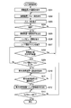
次に、撮像システム10を構成する第1の端末装置2、撮像装置1、及び第2の端末装置3の動作について説明する。まず、スマートフォン等の携帯端末である第1の端末装置2及び第2の端末装置3の動作について、図5に示すフローチャートを参照して説明する。図5に示す端末制御処理は、第1の端末装置2や第2の端末装置3の電源が入っているときに行われる処理である。
Next, operations of the first terminal device 2, the imaging device 1, and the second terminal device 3 that constitute the imaging system 10 will be described. First, operations of the first terminal device 2 and the second terminal device 3 which are portable terminals such as smartphones will be described with reference to a flowchart shown in FIG. The terminal control process shown in FIG. 5 is a process performed when the first terminal apparatus 2 and the second terminal apparatus 3 are turned on.
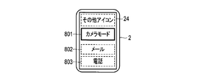
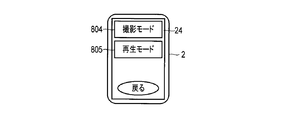
ステップS101において、端末装置の制御部は、表示部に初期画面を表示させる。この初期画面には、端末装置が有する各種機能を発揮させるための複数のアイコンが含まれる。該当するアイコンがユーザによってタッチされることによって、各々の機能が選択される。端末装置が発揮する機能には、本実施形態の第1の端末装置2として機能するカメラモードが含まれる。カメラモードでは、第1の端末装置2は、撮像装置1の制御を行ったり、取得した画像を第2の端末装置3と共有するための処理を行ったりする。また、端末装置が発揮する機能には、本実施形態の第2の端末装置3として機能するシェアモードが含まれる。シェアモードでは、第2の端末装置3は、第1の端末装置2と画像の共有を行う。なお、このステップS101に先立って、前述した撮像装置1、又は第2の端末装置3などの無線機器の識別を行う。
In step S101, the control unit of the terminal device displays an initial screen on the display unit. The initial screen includes a plurality of icons for exhibiting various functions of the terminal device. Each function is selected by touching the corresponding icon by the user. The functions exhibited by the terminal device include a camera mode that functions as the first terminal device 2 of the present embodiment. In the camera mode, the first terminal device 2 controls the imaging device 1 or performs processing for sharing the acquired image with the second terminal device 3. Moreover, the share mode which functions as the 2nd terminal device 3 of this embodiment is contained in the function which a terminal device exhibits. In the share mode, the second terminal device 3 shares an image with the first terminal device 2. Prior to this step S101, wireless devices such as the imaging device 1 or the second terminal device 3 described above are identified.
ステップS102において、端末装置の制御部は、カメラモードが選択されたか否かを判定する。カメラモードが選択されたと判定されたとき、処理はステップS103に進む。ステップS103において、端末装置の制御部は、カメラ制御処理を行う。カメラ制御処理は、端末装置が第1の端末装置2として、撮像装置1を制御する等を行う処理である。カメラ制御処理については後に詳述する。ステップS103の処理の後、処理はステップS109に進む。
In step S102, the control unit of the terminal device determines whether the camera mode is selected. When it is determined that the camera mode has been selected, the process proceeds to step S103. In step S103, the control unit of the terminal device performs camera control processing. The camera control process is a process in which the terminal device controls the imaging device 1 as the first terminal device 2. The camera control process will be described in detail later. After the process of step S103, the process proceeds to step S109.
ステップS102の判定において、カメラモードが選択されていないと判定されたとき、処理はステップS104に進む。ステップS104において、端末装置の制御部は、シェア開始指示を受信したか否かを判定する。シェア開始指示を受信したと判定されたとき、処理はステップS105に進む。ステップS105において、端末装置の制御部は、シェアモード処理を行う。シェアモード処理は、端末装置が第2の端末装置3として、第1の端末装置2と画像の共有を行う処理である。シェアモード処理については、後に詳述する。ステップS105の後、処理はステップS109に進む。
If it is determined in step S102 that the camera mode is not selected, the process proceeds to step S104. In step S104, the control unit of the terminal device determines whether a share start instruction has been received. When it is determined that the share start instruction has been received, the process proceeds to step S105. In step S105, the control unit of the terminal device performs a share mode process. The share mode process is a process in which the terminal device shares an image with the first terminal device 2 as the second terminal device 3. The share mode process will be described in detail later. After step S105, the process proceeds to step S109.
ステップS104において、シェア開始指示を受信していないと判定されたとき、処理はステップS106に進む。ステップS106において、端末装置の制御部は、再生モードが選択されたか否かを判定する。再生モードが選択されたと判定されたとき、処理はステップS107に進む。ステップS107において、端末装置の制御部は、再生モード処理を実行する。
If it is determined in step S104 that a share start instruction has not been received, the process proceeds to step S106. In step S106, the control unit of the terminal device determines whether or not the playback mode has been selected. If it is determined that the playback mode has been selected, the process proceeds to step S107. In step S107, the control unit of the terminal apparatus executes a playback mode process.
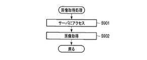
再生モード処理では、端末装置の制御部は、撮像装置1と通信し、撮像装置1の撮像装置記録部13に記録されている画像の再生に係る処理を行う。すなわち、例えば端末装置の制御部は、撮像装置1から記録されている画像のサムネイル画像を取得し、サムネイル画像を表示部に一覧表示をしたり、その中から選択された画像を撮像装置1から取得し、その画像を表示部に表示したり、取得した画像を端末装置の記録部に記録したりする。その後、処理はステップS109に進む。
In the playback mode processing, the control unit of the terminal device communicates with the imaging device 1 and performs processing related to playback of an image recorded in the imaging device recording unit 13 of the imaging device 1. That is, for example, the control unit of the terminal device acquires thumbnail images of images recorded from the imaging device 1, displays a list of thumbnail images on the display unit, or selects an image selected from the thumbnail images from the imaging device 1. Acquire and display the image on the display unit, or record the acquired image on the recording unit of the terminal device. Thereafter, the process proceeds to step S109.
ステップS106において、再生モードが選択されていないと判定されたとき、処理はステップS108に進む。ステップS108において、端末装置の制御部は、カメラ制御処理やシェアモード処理以外の機能を発揮するための処理を行う。この機能には、携帯端末が実行できる各種機能が含まれる。例えば、インターネットブラウジングや、Eメールの送受信や、通話機能や、ゲーム機能等が含まれる。これらの機能の説明については省略する。ステップS108の後、処理はステップS109に進む。
If it is determined in step S106 that the playback mode is not selected, the process proceeds to step S108. In step S108, the control unit of the terminal device performs processing for exhibiting functions other than camera control processing and share mode processing. This function includes various functions that can be executed by the mobile terminal. For example, Internet browsing, transmission / reception of e-mail, a call function, a game function, and the like are included. Description of these functions is omitted. After step S108, the process proceeds to step S109.
ステップS109において、端末装置の制御部は、例えば電源をオフにする操作など、端末制御処理を終了するための入力がなされたか否かを判定する。端末制御処理を終了しないとき、処理はステップS101に戻る。一方、処理を終了するとき、端末制御処理は終了する。
In step S109, the control unit of the terminal device determines whether or not an input for ending the terminal control process has been made, for example, an operation of turning off the power. If the terminal control process is not terminated, the process returns to step S101. On the other hand, when the process ends, the terminal control process ends.
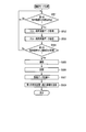
次に、ステップS103で行われるカメラ制御処理について図6に示すフローチャートを参照して説明する。カメラ制御処理は、端末装置が第1の端末装置2として機能するときの処理である。
Next, the camera control process performed in step S103 will be described with reference to the flowchart shown in FIG. The camera control process is a process when the terminal device functions as the first terminal device 2.
ステップS201において、第1の端末制御部21は、撮像装置1へ通信の要求を行う。この通信要求に対して撮像装置1が応答し、第1の端末装置2と撮像装置1との通信が確立される。第1の端末装置2と撮像装置1との通信は、例えば撮像装置1をアクセスポイントとするWi-Fiのインフラストラクチャーモードで行われ得る。
In step S201, the first terminal control unit 21 makes a communication request to the imaging device 1. The imaging device 1 responds to this communication request, and communication between the first terminal device 2 and the imaging device 1 is established. The communication between the first terminal device 2 and the imaging device 1 can be performed, for example, in a Wi-Fi infrastructure mode using the imaging device 1 as an access point.
ステップS202において、第1の端末制御部21は、撮像装置1に、スルー画の要求を行う。この要求を受けた撮像装置1は、撮像動作を行い、スルー画のデータを作成し、作成したスルー画のデータを第1の端末装置2へ送信することを開始する。この際、スルー画のデータは、スルー画用に圧縮されており、画像サイズは小さくなっている。
In step S202, the first terminal control unit 21 requests the imaging device 1 for a through image. Upon receiving this request, the imaging device 1 performs an imaging operation, creates live view data, and starts sending the created live view data to the first terminal device 2. At this time, the data of the through image is compressed for the through image, and the image size is reduced.
ステップS203において、第1の端末制御部21は、撮像装置1からスルー画用画像データを受信して、このスルー画用画像データに基づいて、第1の端末表示部24にスルー画を表示させる。
In step S <b> 203, the first terminal control unit 21 receives the live view image data from the imaging device 1, and causes the first terminal display unit 24 to display the live view image based on the live view image data. .
ステップS204において、第1の端末制御部21は、撮影アイコン24aがタッチされたか否か、すなわち、撮影の実行が指示されたか否かを判定する。撮影アイコン24aがタッチされなかったと判定されたとき、処理はステップS213に進む。撮影アイコン24aがタッチされたと判定されたとき、処理はステップS205に進む。
In step S204, the first terminal control unit 21 determines whether or not the shooting icon 24a is touched, that is, whether or not execution of shooting is instructed. When it is determined that the shooting icon 24a has not been touched, the process proceeds to step S213. When it is determined that the shooting icon 24a has been touched, the process proceeds to step S205.
ステップS205において、第1の端末制御部21は、撮像装置1へ撮影指示を送信する。撮像装置1は、この撮影指示に従い撮像動作を行う。撮像装置1は、得られた画像を撮像装置記録部13に記録する。また、撮像装置1は、撮像により得られた画像データを第1の端末装置2に送信するために、送信に適したサイズに圧縮し、圧縮した画像データ(縮小画像データ)を第1の端末装置2へ送信する。第1の端末装置2から撮像装置1へ送信される撮影指示は、第1の端末装置2が必要としている画像サイズの情報を含んでいる。この画像サイズは、例えば第1の端末表示部24の画面サイズに基づいてもよい。画像サイズが適切に変更されることで、第1の端末装置2と撮像装置1との通信負荷が減少する。
In step S205, the first terminal control unit 21 transmits a shooting instruction to the imaging device 1. The imaging device 1 performs an imaging operation in accordance with this shooting instruction. The imaging device 1 records the obtained image in the imaging device recording unit 13. Further, in order to transmit the image data obtained by the imaging to the first terminal device 2, the imaging device 1 compresses the image data to a size suitable for transmission, and the compressed image data (reduced image data) is the first terminal. Transmit to device 2. The photographing instruction transmitted from the first terminal device 2 to the imaging device 1 includes information on the image size required by the first terminal device 2. This image size may be based on the screen size of the first terminal display unit 24, for example. By appropriately changing the image size, the communication load between the first terminal device 2 and the imaging device 1 is reduced.
ステップS206において、第1の端末制御部21は、撮像装置1から縮小画像データを受信する。第1の端末制御部21は、受信した縮小画像データに基づいて、第1の端末表示部24に縮小画像を表示させる。すなわち、撮影された画像が第1の端末表示部24にレックビュー表示される。このレックビュー表示により、ユーザは、撮影によって取得された画像を確認することができる。
In step S206, the first terminal control unit 21 receives the reduced image data from the imaging device 1. The first terminal control unit 21 displays a reduced image on the first terminal display unit 24 based on the received reduced image data. In other words, the captured image is displayed in rec view on the first terminal display unit 24. With this REC view display, the user can confirm an image acquired by photographing.
ステップS207において、第1の端末制御部21は、第1の端末表示部24にシェア開始アイコン24bを表示させる。シェア開始アイコン24bは、撮影により得られた画像を他の端末装置と共有するときにタッチされるアイコンである。
In step S207, the first terminal control unit 21 causes the first terminal display unit 24 to display the share start icon 24b. The share start icon 24b is an icon that is touched when sharing an image obtained by shooting with another terminal device.
ステップS208において、第1の端末制御部21は、ステップS206において第1の端末表示部24に縮小画像が表示されてから所定時間が経過したか否かを判定する。所定時間が経過したと判定されたとき、処理はステップS213に進む。一方、所定時間が経過していないと判定されたとき、処理はステップS209に進む。
In step S208, the first terminal control unit 21 determines whether or not a predetermined time has elapsed since the reduced image was displayed on the first terminal display unit 24 in step S206. When it is determined that the predetermined time has elapsed, the process proceeds to step S213. On the other hand, when it is determined that the predetermined time has not elapsed, the process proceeds to step S209.
ステップS209において、第1の端末制御部21は、シェア開始アイコン24bがタッチされたか否かを判定する。シェア開始アイコン24bがタッチされていないと判定されたとき、処理はステップS208に戻る。すなわち、シェア開始アイコン24bがタッチされるまで、又は所定の時間が経過するまで、ステップS208及びステップS209の処理は繰り返される。一方、シェア開始アイコン24bがタッチされたと判定されたとき、処理はステップS210に進む。
In step S209, the first terminal control unit 21 determines whether or not the share start icon 24b is touched. When it is determined that the share start icon 24b is not touched, the process returns to step S208. That is, the processes in step S208 and step S209 are repeated until the share start icon 24b is touched or a predetermined time elapses. On the other hand, when it is determined that the share start icon 24b is touched, the process proceeds to step S210.
ステップS210において、第1の端末制御部21は、第2の端末装置3へ通信要求を送信する。この通信要求に対して応答があったとき、第1の端末装置2と第2の端末装置3との通信を開始する。第1の端末装置2と第2の端末装置3との間の通信は、例えばWi-Fiのアドホックモードで行われ得る。
In step S210, the first terminal control unit 21 transmits a communication request to the second terminal device 3. When there is a response to this communication request, communication between the first terminal device 2 and the second terminal device 3 is started. Communication between the first terminal apparatus 2 and the second terminal apparatus 3 can be performed in, for example, a Wi-Fi ad hoc mode.
ステップS211において、第1の端末制御部21は、第2の端末装置3との通信が確立しているか否かを判定する。第2の端末装置3との通信が確立していないと判定されたとき、処理はステップS211を繰り返し、通信が確立するまで待機する。一方、第2の端末装置3との通信が確立していると判定されたとき、処理はステップS212に進む。
In step S211, the first terminal control unit 21 determines whether communication with the second terminal device 3 has been established. When it is determined that communication with the second terminal device 3 has not been established, the process repeats step S211 and waits until communication is established. On the other hand, when it is determined that communication with the second terminal device 3 is established, the process proceeds to step S212.
ステップS212において、第1の端末制御部21は、第2の端末装置3へシェア開始指示を送信する。なお、シェア開始指示は、撮像装置1を特定するための情報や、共有すべき画像を特定するための情報や、撮像装置1と第2の端末装置3との間の通信を確立するために必要な接続情報を含む。その後、処理はステップS213に進む。
In step S212, the first terminal control unit 21 transmits a share start instruction to the second terminal device 3. The share start instruction is used to establish information for specifying the imaging device 1, information for specifying an image to be shared, and communication between the imaging device 1 and the second terminal device 3. Contains necessary connection information. Thereafter, the process proceeds to step S213.
ステップS213において、第1の端末制御部21は、カメラモードを終了させるか否かを判定する。カメラモードを終了させないと判定されたとき、処理はステップS202に戻る。カメラモードを終了させると判定されたとき、当該カメラ制御処理は終了し、処理は図5を参照して説明した端末制御処理に戻る。
In step S213, the first terminal control unit 21 determines whether to end the camera mode. If it is determined not to end the camera mode, the process returns to step S202. When it is determined to end the camera mode, the camera control process ends, and the process returns to the terminal control process described with reference to FIG.
次に、端末制御処理のステップS105で行われるシェアモード処理について、図7に示すフローチャートを参照して説明する。シェアモード処理は、端末装置が第2の端末装置3として機能するための処理である。
Next, the share mode process performed in step S105 of the terminal control process will be described with reference to the flowchart shown in FIG. The share mode process is a process for the terminal device to function as the second terminal device 3.
ステップS301において、第2の端末制御部31は、第1の端末装置2からシェア開始指示を受信する。この指示には、撮像装置1を特定するための情報や、共有すべき画像を特定するための情報や、撮像装置1と第2の端末装置3との間の通信を確立するために必要な接続情報が含まれる。
In step S301, the second terminal control unit 31 receives a share start instruction from the first terminal device 2. This instruction is necessary for establishing information for specifying the imaging device 1, information for specifying an image to be shared, and communication between the imaging device 1 and the second terminal device 3. Contains connection information.
ステップS302において、第2の端末制御部31は、撮像装置1と第2の端末装置3との通信を確立する。第2の端末制御部31は、シェア開始指示に含まれる撮像装置1を特定するための情報に基づいて、撮像装置1への通信要求の送信を開始する。この通信要求に対して撮像装置1が応答し、第2の端末装置3と撮像装置1との通信が開始する。撮像装置1と第2の端末装置3との通信は、例えば撮像装置1をアクセスポイントとするWi-Fiのインフラストラクチャーモードで行われ得る。
In step S302, the second terminal control unit 31 establishes communication between the imaging device 1 and the second terminal device 3. The second terminal control unit 31 starts transmitting a communication request to the imaging device 1 based on information for specifying the imaging device 1 included in the share start instruction. The imaging device 1 responds to this communication request, and communication between the second terminal device 3 and the imaging device 1 starts. Communication between the imaging device 1 and the second terminal device 3 can be performed in, for example, a Wi-Fi infrastructure mode using the imaging device 1 as an access point.
ステップS303において、第2の端末制御部31は、シェア開始指示に含まれる共有すべき画像を特定するための情報に基づいて、撮像装置1へ画像要求信号を送信する。この画像要求信号は、第1の端末装置2が指定した画像を特定するための情報や、受け取りを希望する画像サイズ等の情報を含む。画像要求信号を受信した撮像装置1は、撮像装置記録部13に記録されている画像データに基づいて、希望されたサイズの画像のデータを作成し、作成した画像データを第2の端末装置3へと送信する。
In step S303, the second terminal control unit 31 transmits an image request signal to the imaging device 1 based on information for specifying an image to be shared included in the share start instruction. The image request signal includes information for specifying an image designated by the first terminal device 2 and information such as an image size desired to be received. The imaging device 1 that has received the image request signal creates image data of a desired size based on the image data recorded in the imaging device recording unit 13, and uses the created image data as the second terminal device 3. Send to.
ステップS304において、第2の端末制御部31は、撮像装置1から画像データを受信する。ステップS305において、第2の端末制御部31は、ステップS304において受信した画像データに基づく画像を第2の端末表示部34に表示させる。受信した画像データが第2の端末記録部36に記録されてもよい。その後、シェアモード処理は終了し、処理は図5を参照して説明している端末制御処理に戻る。
In step S304, the second terminal control unit 31 receives image data from the imaging apparatus 1. In step S305, the second terminal control unit 31 causes the second terminal display unit 34 to display an image based on the image data received in step S304. The received image data may be recorded in the second terminal recording unit 36. Thereafter, the share mode process ends, and the process returns to the terminal control process described with reference to FIG.
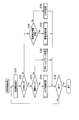
次に、撮像装置1の動作について、図8に示すフローチャートを参照して説明する。図8に示す撮像装置制御処理は、例えば撮像装置1の電源が入れられたときに開始する。
Next, the operation of the imaging apparatus 1 will be described with reference to the flowchart shown in FIG. The imaging device control process shown in FIG. 8 starts when the imaging device 1 is turned on, for example.
ステップS401において、撮像装置制御部11は、撮像装置1の電源がオンであるか否かを判定する。電源がオンでないと判定されたとき、撮像装置制御処理は終了する。一方、電源がオンであると判定されたとき、処理はステップS402に進む。このステップS402において、前述のように撮像装置1はアクセスポイントとして動作し、Wi-Fi通信はインフラストラクチャーモードで動作する。ステップS402において、撮像装置制御部11は、端末装置からの通信要求を待つ。
In step S401, the imaging device control unit 11 determines whether or not the power of the imaging device 1 is on. When it is determined that the power is not on, the imaging device control process ends. On the other hand, when it is determined that the power is on, the process proceeds to step S402. In step S402, the imaging device 1 operates as an access point as described above, and Wi-Fi communication operates in the infrastructure mode. In step S402, the imaging device control unit 11 waits for a communication request from the terminal device.
ステップS403において、撮像装置制御部11は、端末装置から撮影モードに係るアクセスがあるか否かを判定する。撮影モードに係るアクセスとは、第1の端末装置2がカメラ制御処理において撮像装置1に撮影を行わせるために行う通信要求である。撮影モードに係るアクセスがあると判定されたとき、処理はステップS404に進む。
In step S403, the imaging device control unit 11 determines whether there is an access related to the shooting mode from the terminal device. The access related to the shooting mode is a communication request that the first terminal device 2 makes to cause the imaging device 1 to perform shooting in the camera control process. When it is determined that there is an access related to the shooting mode, the process proceeds to step S404.
ステップS404において、撮像装置制御部11は、撮影モード処理を行う。撮影モード処理は、撮像装置1が撮像動作を行い、スルー画を第1の端末装置2に送信したり、静止画を取得して記録し、そのレックビュー画像を第1の端末装置2に送信したりする処理である。撮影モード処理については、後に詳述する。撮影モード処理の後、処理はステップS401に戻る。
In step S404, the imaging device control unit 11 performs shooting mode processing. In the shooting mode processing, the imaging device 1 performs an imaging operation, transmits a through image to the first terminal device 2, acquires and records a still image, and transmits the rec view image to the first terminal device 2. It is processing to do. The shooting mode process will be described in detail later. After the shooting mode process, the process returns to step S401.
ステップS403において、撮影モードに係るアクセスがないと判定されたとき、処理はステップS405に進む。ステップS405において、撮像装置制御部11は、シェアモードに係るアクセスがあるか否かを判定する。シェアモードに係るアクセスとは、第2の端末装置3がシェアモード処理において撮像装置1に画像を要求するために行う通信要求である。シェアモードに係るアクセスがあると判定されたとき、処理はステップS406に進む。
If it is determined in step S403 that there is no access related to the shooting mode, the process proceeds to step S405. In step S405, the imaging device control unit 11 determines whether there is an access related to the share mode. The access related to the share mode is a communication request that the second terminal device 3 makes to request an image from the imaging device 1 in the share mode process. When it is determined that there is an access related to the share mode, the process proceeds to step S406.
ステップS406において、撮像装置制御部11は、画像送信処理を行う。画像送信処理は、第2の端末装置3からの要求に応じて、要求された画像を第2の端末装置3に送信する処理である。画像送信処理については、後に詳述する。画像送信処理の後、処理はステップS401に戻る。ここで、第2の端末装置3からの要求に応じてと書いたが、もちろん、要求があることを想定して、第2の端末装置3にプッシュ型で送信してもよい。
In step S406, the imaging device control unit 11 performs an image transmission process. The image transmission process is a process of transmitting a requested image to the second terminal device 3 in response to a request from the second terminal device 3. The image transmission process will be described later in detail. After the image transmission process, the process returns to step S401. Here, it was written in response to a request from the second terminal device 3, but of course, it may be transmitted to the second terminal device 3 in a push type assuming that there is a request.
ステップS405において、シェアモードに係るアクセスがないと判定されたとき、処理はステップS407に進む。ステップS407において、撮像装置制御部11は、再生モードに係るアクセスがあるか否かを判定する。再生モードに係るアクセスとは、端末装置が再生モード処理において撮像装置1に画像を要求するために行う通信要求である。再生モードに係るアクセスがないと判定されたとき、処理はステップS401に戻る。一方、再生モードに係るアクセスがあると判定されたとき、処理はステップS408に進む。
When it is determined in step S405 that there is no access related to the share mode, the process proceeds to step S407. In step S407, the imaging device control unit 11 determines whether there is an access related to the playback mode. The access related to the reproduction mode is a communication request that the terminal device makes to request an image from the imaging apparatus 1 in the reproduction mode process. When it is determined that there is no access related to the playback mode, the process returns to step S401. On the other hand, when it is determined that there is an access related to the playback mode, the process proceeds to step S408.
ステップS408において、撮像装置制御部11は、画像再生処理を行う。画像再生処理では、端末装置の要求に応じて撮像装置記録部13に記録されている画像を端末装置へ送信する。画像再生処理については、説明を省略する。画像再生処理の後、処理はステップS401に戻る。
In step S408, the imaging device control unit 11 performs an image reproduction process. In the image reproduction process, an image recorded in the imaging device recording unit 13 is transmitted to the terminal device in response to a request from the terminal device. Description of the image reproduction process is omitted. After the image reproduction process, the process returns to step S401.
次に、ステップS404で行われる撮影モード処理について図9に示すフローチャートを参照して説明する。撮影モード処理は、第1の端末装置2がカメラ制御処理によって撮像装置1の制御を開始したときに実行される。
Next, the shooting mode process performed in step S404 will be described with reference to the flowchart shown in FIG. The shooting mode process is executed when the first terminal apparatus 2 starts controlling the imaging apparatus 1 by the camera control process.
ステップS501において、撮像装置制御部11は、第1の端末装置2との通信が確立したか否かを判定する。第1の端末装置2は、カメラ制御処理のステップS201において撮像装置1との通信を要求し、ステップS202において撮影モード指示を送信する。撮像装置1は、これらの要求に応じて、第1の端末装置2との通信を開始する。第1の端末装置2との通信が確立していないと判定されたとき、処理はステップS501に戻り、第1の端末装置2との通信の確立を試みる。第1の端末装置2との通信が確立していると判定されたとき、処理はステップS502に進む。
In step S501, the imaging device control unit 11 determines whether communication with the first terminal device 2 has been established. The first terminal device 2 requests communication with the imaging device 1 in step S201 of the camera control process, and transmits a shooting mode instruction in step S202. The imaging device 1 starts communication with the first terminal device 2 in response to these requests. When it is determined that communication with the first terminal device 2 has not been established, the process returns to step S501 and attempts to establish communication with the first terminal device 2. When it is determined that communication with the first terminal device 2 is established, the process proceeds to step S502.
撮像装置1と第1の端末装置2との通信が確立すると、撮影モード指示に基づいて、ステップS502において、撮像装置制御部11は、撮像を開始して、撮像によりスルー画用画像データを取得する。すなわち、撮像部12において、光学系を介して入射した光により撮像素子の撮像面に被写体像が形成される。撮像部12は、この被写体像に基づく画像データを生成し、撮像装置制御部11は、この画像データを取得する。撮像装置制御部11は、撮像素子から取得した画像データをスルー画用に画像処理する。この画像処理には、画像の縮小が含まれる。このように、撮像装置制御部11は、画像処理によってスルー画用画像データを生成する。
When communication between the imaging device 1 and the first terminal device 2 is established, based on the shooting mode instruction, the imaging device control unit 11 starts imaging in step S502 and acquires through image data by imaging. To do. That is, in the imaging unit 12, a subject image is formed on the imaging surface of the imaging element by light incident through the optical system. The imaging unit 12 generates image data based on the subject image, and the imaging device control unit 11 acquires the image data. The imaging device control unit 11 performs image processing on the image data acquired from the imaging element for a through image. This image processing includes image reduction. As described above, the imaging device control unit 11 generates through image data by image processing.
ステップS503において、撮像装置制御部11は、第1の端末装置2へスルー画用画像データを送信する。この画像データを受信した第1の端末装置2は、ステップS206でスルー画を表示する。
In step S503, the imaging device control unit 11 transmits the live view image data to the first terminal device 2. The first terminal device 2 that has received the image data displays a through image in step S206.
ステップS504において、撮像装置制御部11は、第1の端末装置2から撮影指示を受信したか否かを判定する。この撮影指示は、第1の端末装置2がステップS205で送信する撮影指示である。第1の端末装置2から撮影指示を受信していないと判定されたとき、処理はステップS501に戻る。一方、第1の端末装置2から撮影指示を受信したと判定されたとき、処理はステップS505に進む。
In step S504, the imaging device control unit 11 determines whether a shooting instruction is received from the first terminal device 2. This photographing instruction is a photographing instruction transmitted by the first terminal device 2 in step S205. When it is determined that a shooting instruction has not been received from the first terminal device 2, the process returns to step S501. On the other hand, when it is determined that a shooting instruction has been received from the first terminal device 2, the process proceeds to step S505.
ステップS505において、撮像装置制御部11は、撮像部12に撮像動作を実行させる。ステップS506において、撮像装置制御部11は、撮影により取得された画像データを撮像装置記録部13に記録する。
In step S505, the imaging device control unit 11 causes the imaging unit 12 to perform an imaging operation. In step S <b> 506, the imaging device control unit 11 records the image data acquired by shooting in the imaging device recording unit 13.
ステップS507において、撮像装置制御部11は、撮影により取得された画像データの画像サイズを縮小させる。ステップS508において、撮像装置制御部11は、ステップS507において得られた縮小画像データを第1の端末装置2へ送信する。その後、撮影モード処理は終了し、処理は図8を参照して説明した撮像装置制御処理に戻る。
In step S507, the imaging device control unit 11 reduces the image size of the image data acquired by shooting. In step S508, the imaging device control unit 11 transmits the reduced image data obtained in step S507 to the first terminal device 2. Thereafter, the shooting mode process ends, and the process returns to the imaging device control process described with reference to FIG.
次に、ステップS406で行われる画像送信処理について図10に示すフローチャートを参照して説明する。画像送信処理は、第2の端末装置3がシェアモード処理によって撮像装置1に画像の要求を開始したときに実施される。
Next, the image transmission process performed in step S406 will be described with reference to the flowchart shown in FIG. The image transmission process is performed when the second terminal apparatus 3 starts requesting an image from the imaging apparatus 1 by the share mode process.
ステップS601において、撮像装置制御部11は、第2の端末装置3との通信が確立したか否かを判定する。第2の端末装置3は、シェアモード処理のステップS302において撮像装置1との通信を要求し、ステップS303においてシェア画像要求指示を送信する。撮像装置1は、これらの要求に応じて、第2の端末装置3との通信を開始する。第2の端末装置3との通信が確立していなかったと判定されたとき、処理はステップS601に戻り、第2の端末装置3との通信の確立を試みる。第2の端末装置3との通信が確立していると判定されたとき、処理はステップS602に進む。
In step S601, the imaging device control unit 11 determines whether communication with the second terminal device 3 has been established. The second terminal device 3 requests communication with the imaging device 1 in step S302 of the share mode process, and transmits a share image request instruction in step S303. The imaging device 1 starts communication with the second terminal device 3 in response to these requests. When it is determined that communication with the second terminal device 3 has not been established, the process returns to step S601 and attempts to establish communication with the second terminal device 3. When it is determined that communication with the second terminal device 3 is established, the process proceeds to step S602.
撮像装置1と第2の端末装置3との通信が確立すると、撮像装置1は、シェア画像要求指示に基づいて、ステップS602の処理を行う。シェア画像要求指示には、第2の端末装置3が要求している画像を特定するための情報と、第2の端末装置3が要求している画像サイズの情報とが含まれる。
When communication between the imaging device 1 and the second terminal device 3 is established, the imaging device 1 performs the process of step S602 based on the share image request instruction. The share image request instruction includes information for specifying the image requested by the second terminal device 3 and information on the image size requested by the second terminal device 3.
ステップS602において、撮像装置制御部11は、要求された画像を、要求されたサイズに縮小する。ステップS603において、撮像装置制御部11は、ステップS602において縮小した画像データを第2の端末装置3へ送信する。このようにして、第2の端末装置3は、第1の端末装置2と共有する画像を取得する。その後、撮影モード処理は終了し、処理は図8を参照して説明した撮像装置制御処理に戻る。
In step S602, the imaging device control unit 11 reduces the requested image to the requested size. In step S <b> 603, the imaging device control unit 11 transmits the image data reduced in step S <b> 602 to the second terminal device 3. In this way, the second terminal device 3 acquires an image shared with the first terminal device 2. Thereafter, the shooting mode process ends, and the process returns to the imaging device control process described with reference to FIG.
以上のように、本実施形態の撮像システム10では、システム全体として通信負荷の低減が図られている。すなわち、第1の端末装置2は、撮像装置1の撮像動作を制御しているが、ここで必要なスルー画やレックビュー画像は、適当な大きさに圧縮されて撮像装置1から第1の端末装置2へと送信されている。また、撮影によって取得された画像が第1の端末装置2と第2の端末装置3とで共有されているが、この画像は、撮像装置1から第2の端末装置3へと送信されている。すなわち、画像は、第1の端末装置2を介さずに、画像が記録されている撮像装置1から第2の端末装置3へと送信される。このとき、第1の端末装置2と第2の端末装置3との間では、画像データそのものではなく、画像を特定するために必要な情報のみが送受信されている。画像を特定するための情報は、画像データよりもはるかにサイズが小さい。また、撮像装置1から第2の端末装置3へ画像が送信される際も、送信される画像は、第2の端末装置3が必要としている画像サイズに調整される。本実施形態に係る技術は、通信速度に制限があることが多い無線通信によって装置間の通信が行われるとき、特に効果を奏する。このような点に考慮することによって、ユーザのストレスを軽減することが可能となる。
As described above, in the imaging system 10 of this embodiment, the communication load is reduced as a whole system. That is, the first terminal device 2 controls the imaging operation of the imaging device 1, but the through image and the REC view image necessary here are compressed to an appropriate size from the imaging device 1 to the first image. It is transmitted to the terminal device 2. In addition, an image acquired by shooting is shared between the first terminal device 2 and the second terminal device 3, but this image is transmitted from the imaging device 1 to the second terminal device 3. . That is, the image is transmitted from the imaging device 1 in which the image is recorded to the second terminal device 3 without going through the first terminal device 2. At this time, not the image data itself but only information necessary for specifying an image is transmitted and received between the first terminal device 2 and the second terminal device 3. Information for identifying an image is much smaller in size than image data. In addition, when an image is transmitted from the imaging device 1 to the second terminal device 3, the transmitted image is adjusted to the image size required by the second terminal device 3. The technique according to the present embodiment is particularly effective when communication between apparatuses is performed by wireless communication in which communication speed is often limited. By considering such points, it is possible to reduce the stress on the user.
なお、第2の端末装置3が取得する画像は、第1の端末装置2が取得した画像と完全に同一でなくてもよい。すなわち、例えば、第2の端末装置3が取得する画像は、第1の端末装置2の制御下で取得された画像の一部がトリミングされたものであってもよい。この場合、第1の端末装置2は、撮影後のレックビュー表示において、ユーザによるトリミングの指示を取得する。ここで取得されたトリミングに係る情報が、第1の端末装置2から第2の端末装置3へと送信されるシェア開始指示に含まれる。第2の端末装置3は、第1の端末装置2から取得したトリミングに係る情報を撮像装置1へと送信する。撮像装置1は、このトリミングに係る情報に基づいて、共有すべき画像をトリミングし、トリミング後の画像を第2の端末装置3へと送信する。
Note that the image acquired by the second terminal device 3 may not be completely the same as the image acquired by the first terminal device 2. That is, for example, the image acquired by the second terminal device 3 may be a trimmed part of the image acquired under the control of the first terminal device 2. In this case, the first terminal apparatus 2 acquires a trimming instruction from the user in the REC view display after shooting. The information related to the trimming acquired here is included in the share start instruction transmitted from the first terminal device 2 to the second terminal device 3. The second terminal device 3 transmits information related to trimming acquired from the first terminal device 2 to the imaging device 1. The imaging device 1 trims the image to be shared based on the information related to the trimming, and transmits the trimmed image to the second terminal device 3.
また、トリミングに限らず、色調等の画像処理の内容又は種類に係る加工情報が第1の端末装置2から第2の端末装置3へと送信され、この情報に基づいて加工された画像が、撮像装置1から第2の端末装置3へと送信されてもよい。このように、撮像装置1から第2の端末装置3へと送信される画像は、撮像された画像に対して種々の画像処理が行われた画像でもよい。
Further, not only trimming but also processing information related to the content or type of image processing such as color tone is transmitted from the first terminal device 2 to the second terminal device 3, and an image processed based on this information is The image may be transmitted from the imaging device 1 to the second terminal device 3. Thus, the image transmitted from the imaging device 1 to the second terminal device 3 may be an image obtained by performing various image processes on the captured image.
また、本実施形態では、撮像装置1による撮像直後に、撮像した画像について第1の端末装置2と第2の端末装置3とで画像を共有する例を示した。しかしながら、これに限らない。例えば、撮像装置1と第1の端末装置2とが行う再生モードにおいて選択された画像が、第2の端末装置3と共有されてもよい。例えば、第1の端末装置2が、撮像装置記録部13に記録されている画像のサムネイル画像を撮像装置1に要求して、サムネイル画像を第1の端末表示部24に一覧表示する。ここで選択された画像について、第2の端末装置3と共有される。このとき、撮像装置1から第2の端末装置3へと選択された画像のデータが送信される。この場合も、撮像装置1から第2の端末装置3へと必要なサイズの画像が送信されるので、特に第1の端末装置2の通信負荷が減少する。
Further, in the present embodiment, an example is shown in which the first terminal device 2 and the second terminal device 3 share an image of the captured image immediately after imaging by the imaging device 1. However, the present invention is not limited to this. For example, an image selected in a playback mode performed by the imaging device 1 and the first terminal device 2 may be shared with the second terminal device 3. For example, the first terminal device 2 requests the image capturing device 1 for thumbnail images of images recorded in the image capturing device recording unit 13 and displays the thumbnail images in a list on the first terminal display unit 24. The image selected here is shared with the second terminal device 3. At this time, the selected image data is transmitted from the imaging device 1 to the second terminal device 3. Also in this case, since an image of a necessary size is transmitted from the imaging device 1 to the second terminal device 3, the communication load of the first terminal device 2 is particularly reduced.
上述の実施形態では、第2の端末装置3は、第1の端末装置2と同様の構成と機能を有する端末であるとして説明を行った。しかしながらこれに限らない。例えば第2の端末装置は、プリンタ等であってもよい。すなわち、第1の端末装置2が撮像装置1に撮影を行わせ、得られた画像をプリントしたいとき、第1の端末装置2は、当該プリンタに撮像装置1から画像を取得してその画像を印刷するように指示をする。この指示を受けたプリンタは、第1の端末装置2から得た情報に基づいて、撮像装置1から指定された画像データを取得して、当該画像を印刷する。例えばプリンタで高精細な画像を印刷するためには、撮像装置1からプリンタへ送信される画像データは、情報量が多い画像データとなる。このようにプリンタを含むシステムにおいても、本実施形態によれば、システム全体としての通信負荷が減少する。その他、第2の端末装置3は、高精細の例えば、4K、8Kといった表示装置であってもよい。また、第2の端末装置3に相当するものは、各種端末に限らず複数の装置からなるシステムであってもよい。その場合も、上述の構成や動作と同様構成や動作が用いられ得る。
In the above-described embodiment, the second terminal device 3 has been described as a terminal having the same configuration and function as the first terminal device 2. However, it is not limited to this. For example, the second terminal device may be a printer or the like. That is, when the first terminal device 2 causes the imaging device 1 to take a picture and wants to print the obtained image, the first terminal device 2 obtains the image from the imaging device 1 by the printer and displays the image. Instruct to print. Upon receiving this instruction, the printer acquires the image data designated from the imaging device 1 based on the information obtained from the first terminal device 2, and prints the image. For example, in order to print a high-definition image with a printer, the image data transmitted from the imaging device 1 to the printer is image data with a large amount of information. Thus, even in a system including a printer, according to the present embodiment, the communication load of the entire system is reduced. In addition, the second terminal device 3 may be a high-definition display device such as 4K or 8K. Further, what corresponds to the second terminal device 3 is not limited to various terminals, and may be a system including a plurality of devices. In this case, the same configuration and operation as those described above can be used.
上述の実施形態では、撮像装置としてレンズ型カメラの場合を例に挙げて説明した。しかしながらこれに限らず、撮像装置は、一般的なデジタルカメラでもよい。例えば第1の端末装置としてのタブレット端末が、デジタルカメラに記録されている画像について選択や加工の指定を行い、第2の端末装置としてのプリンタが、タブレット端末が指定した画像や指定した加工を施した画像のデータを受信してプリントを行う場合などに、本実施形態の技術が用いられ得る。
In the above-described embodiment, the case where a lens-type camera is used as the imaging device has been described as an example. However, the present invention is not limited thereto, and the imaging device may be a general digital camera. For example, a tablet terminal as a first terminal device selects and specifies processing for an image recorded in a digital camera, and a printer as a second terminal device performs an image specified by the tablet terminal and a specified processing. The technique of the present embodiment can be used when the image data is received and printed.
このように、第1の端末装置と第2の端末装置とは、どのような装置であってもよい。すなわち、第1の端末装置及び第2の端末装置は、撮像装置から見て外部の機器であり、それぞれ第1の外部機器及び第2の外部機器に相当する。
Thus, the first terminal device and the second terminal device may be any device. In other words, the first terminal device and the second terminal device are external devices when viewed from the imaging device, and correspond to the first external device and the second external device, respectively.
また、上述の実施形態では、無線通信として主にWi-Fiが用いられる場合を例に挙げて説明した。しかしながら、これに限らない。上述したとおり、Bluetoothのマルチペアリングモードを利用したり、NFC、トランスファージェット等を併用してもよい。さらに、別な方式が用いられてもよい。例えば、ZigBee(登録商標)やZ-Wave(登録商標)等が用いられてもよい。また、W-CDMA(登録商標)等を含む3GやLTEといった移動体通信システムが用いられてもよい。また、IrDA等の赤外線通信を含む光無線通信が用いられてもよい。これらの通信方式は、それぞれの通信方式の速度や通信距離といった特徴に応じて、撮像装置1との通信に用いられたり、端末装置間の通信に用いられたり、適宜に使用される。
In the above-described embodiment, the case where Wi-Fi is mainly used as wireless communication has been described as an example. However, the present invention is not limited to this. As described above, the Bluetooth multi-pairing mode may be used, or NFC, transfer jet, or the like may be used in combination. Furthermore, another method may be used. For example, ZigBee (registered trademark), Z-Wave (registered trademark), or the like may be used. Also, a mobile communication system such as 3G or LTE including W-CDMA (registered trademark) may be used. Further, optical wireless communication including infrared communication such as IrDA may be used. These communication methods are used for communication with the imaging device 1, used for communication between terminal devices, or appropriately used according to the characteristics such as speed and communication distance of each communication method.
[第2の実施形態]
第2の実施形態について説明する。ここでは、第1の実施形態との相違点について説明し、同一の部分については、同一の符号を付してその説明を省略する。本実施形態の構成例の概略を図11に示す。本実施形態では、共有すべき画像がネットワーク9を介してサーバ4に記録される。サーバ4に記録された画像は、第2の端末装置3やプリンタ5等のその他の装置からの要求に応じてそれら装置に送信される。 [Second Embodiment]
A second embodiment will be described. Here, differences from the first embodiment will be described, and the same portions will be denoted by the same reference numerals and description thereof will be omitted. An outline of a configuration example of the present embodiment is shown in FIG. In the present embodiment, an image to be shared is recorded in the server 4 via thenetwork 9. The image recorded in the server 4 is transmitted to these devices in response to requests from other devices such as the second terminal device 3 and the printer 5.
第2の実施形態について説明する。ここでは、第1の実施形態との相違点について説明し、同一の部分については、同一の符号を付してその説明を省略する。本実施形態の構成例の概略を図11に示す。本実施形態では、共有すべき画像がネットワーク9を介してサーバ4に記録される。サーバ4に記録された画像は、第2の端末装置3やプリンタ5等のその他の装置からの要求に応じてそれら装置に送信される。 [Second Embodiment]
A second embodiment will be described. Here, differences from the first embodiment will be described, and the same portions will be denoted by the same reference numerals and description thereof will be omitted. An outline of a configuration example of the present embodiment is shown in FIG. In the present embodiment, an image to be shared is recorded in the server 4 via the
サーバ4は、サーバ制御部41と、サーバ通信部43と、サーバ記録部46とを有する。サーバ通信部43は、ネットワーク9を介して各種装置と通信をする。サーバ記録部46は、ネットワーク9を介して取得したデータ等を記録する。サーバ記録部46に記録されたデータは、ネットワーク9を介して要求に応じて各種端末に送信される。サーバ制御部41は、サーバ4の各部の動作を制御する。サーバ制御部41は、アクセス判定部411と、通信制御部412と、アルバム作成部413とを有する。アクセス判定部411は、サーバ4にアクセスする端末を判定する。通信制御部412は、サーバ通信部43を介して行われる通信を制御する。アルバム作成部413は、サーバ4上に作成されるアルバムの作成に係る動作を制御する。アルバム作成部413は、サーバ4にアクセスする端末の指示に基づいて、サーバ4に記録された複数の画像を関連付ける等してアルバムを作成する。
The server 4 includes a server control unit 41, a server communication unit 43, and a server recording unit 46. The server communication unit 43 communicates with various devices via the network 9. The server recording unit 46 records data acquired via the network 9. Data recorded in the server recording unit 46 is transmitted to various terminals in response to requests via the network 9. The server control unit 41 controls the operation of each unit of the server 4. The server control unit 41 includes an access determination unit 411, a communication control unit 412, and an album creation unit 413. The access determination unit 411 determines a terminal that accesses the server 4. The communication control unit 412 controls communication performed via the server communication unit 43. The album creating unit 413 controls operations related to creating an album created on the server 4. The album creating unit 413 creates an album by associating a plurality of images recorded in the server 4 based on an instruction from a terminal that accesses the server 4.
本実施形態に係る第1の端末装置2や第2の端末装置3で行われる端末制御処理について、図12に示すフローチャートを参照して説明する。また、端末表示部に表示される画像の例を図13A乃至図13Eを参照して説明する。
The terminal control processing performed by the first terminal device 2 and the second terminal device 3 according to the present embodiment will be described with reference to the flowchart shown in FIG. Examples of images displayed on the terminal display unit will be described with reference to FIGS. 13A to 13E.
ステップS701において、端末制御部は、初期画面を端末表示部に表示させる。端末表示部には、例えば図13Aのような画像が表示される。すなわち、端末表示部には、各種アイコンが表示される。このアイコンには、撮像装置1と通信し、撮像装置1の動作を制御するためのカメラモードアイコン801や、メール機能を発揮するためのメールアイコン802や、通話機能を発揮するための電話アイコン803等が含まれる。
In step S701, the terminal control unit displays an initial screen on the terminal display unit. For example, an image as shown in FIG. 13A is displayed on the terminal display unit. That is, various icons are displayed on the terminal display unit. This icon includes a camera mode icon 801 for communicating with the imaging apparatus 1 and controlling the operation of the imaging apparatus 1, a mail icon 802 for exhibiting a mail function, and a telephone icon 803 for exhibiting a call function. Etc. are included.
ステップS702において、端末制御部は、カメラモードが選択されたか否かを判定する。カメラモードが選択されたとき、処理はステップS703に進む。このとき、端末装置は、第1の端末装置2として機能する。カメラモードが選択されたとき、例えば図13Bに示すような画面が、第1の端末表示部24に表示される。この画面には、撮像装置1に撮像動作を行わせるための撮影モードアイコン804や、撮像装置1に再生動作を行わせるための再生モードアイコン805が含まれる。
In step S702, the terminal control unit determines whether the camera mode is selected. When the camera mode is selected, the process proceeds to step S703. At this time, the terminal device functions as the first terminal device 2. When the camera mode is selected, for example, a screen as shown in FIG. 13B is displayed on the first terminal display unit 24. This screen includes a shooting mode icon 804 for causing the imaging apparatus 1 to perform an imaging operation, and a playback mode icon 805 for causing the imaging apparatus 1 to perform a playback operation.
ステップS703において、第1の端末制御部21は、撮影モードアイコン804がタッチされて撮影モードが選択されたか否かを判定する。撮影モードが選択されたとき、処理はステップS704に進む。
In step S703, the first terminal control unit 21 determines whether or not the shooting mode icon 804 is touched to select the shooting mode. When the shooting mode is selected, the process proceeds to step S704.
ステップS704において、第1の端末制御部21は、カメラ制御処理を行う。カメラ制御処理は、例えば上述した第1の実施形態と同様に、図6を参照して説明した処理である。なお、本実施形態に係るカメラ制御処理では、静止画の撮影の後に、シェアモードを実施するために第2の端末装置3と通信しなくてもよい。カメラ制御処理中には、例えば図13Cのような画像が第1の端末表示部24に表示される。すなわち、第1の端末表示部24には、スルー画806が表示され、また、撮影を行うための撮影アイコン24aが表示される。カメラ制御処理の後、処理はステップS709に進む。
In step S704, the first terminal control unit 21 performs a camera control process. The camera control process is the process described with reference to FIG. 6 as in the first embodiment described above, for example. In the camera control process according to the present embodiment, it is not necessary to communicate with the second terminal device 3 in order to implement the share mode after taking a still image. During the camera control process, for example, an image as shown in FIG. 13C is displayed on the first terminal display unit 24. That is, the first terminal display unit 24 displays a through image 806 and a shooting icon 24a for shooting. After the camera control process, the process proceeds to step S709.
ステップS703において、撮影モードが選択されていないと判定されたとき、処理はステップS705に進む。ステップS705において、第1の端末制御部21は、再生・シェアモード処理を実行する。再生・シェアモード処理について、図14に示すフローチャートを参照して説明する。
When it is determined in step S703 that the shooting mode is not selected, the process proceeds to step S705. In step S705, the first terminal control unit 21 executes playback / share mode processing. The reproduction / share mode processing will be described with reference to the flowchart shown in FIG.
ステップS801において、第1の端末制御部21は、撮像装置1に画像一覧を要求する。画像一覧を要求された撮像装置1は、撮像装置記録部13に記録されている画像のサムネイル画像を第1の端末装置2に送信する。
In step S801, the first terminal control unit 21 requests the image list from the imaging device 1. The imaging device 1 requested for the image list transmits a thumbnail image of the image recorded in the imaging device recording unit 13 to the first terminal device 2.
ステップS802において、第1の端末制御部21は、受信したサムネイル画像を第1の端末表示部24に一覧表示する。第1の端末表示部24には、例えば、図13Dのような画像が表示される。すなわち、第1の端末表示部24には、複数のサムネイル画像807が一覧表示される。
In step S802, the first terminal control unit 21 displays a list of received thumbnail images on the first terminal display unit 24. For example, an image as illustrated in FIG. 13D is displayed on the first terminal display unit 24. That is, a list of a plurality of thumbnail images 807 is displayed on the first terminal display unit 24.
ステップS803において、第1の端末制御部21は、画像が選択されたか否かを判定する。画像が選択されていないとき、処理はステップS804に進む。ステップS804において、第1の端末制御部21は、戻るアイコン808がタッチされたか否かを判定する。戻るアイコン808がタッチされていないとき、処理はステップS802に戻る。一方、戻るアイコンがタッチされたと判定されたとき、再生・シェアモード処理は終了し、図12を参照して説明している端末制御処理に戻る。
In step S803, the first terminal control unit 21 determines whether an image is selected. If no image is selected, the process proceeds to step S804. In step S804, the first terminal control unit 21 determines whether or not the return icon 808 has been touched. When the return icon 808 is not touched, the process returns to step S802. On the other hand, when it is determined that the return icon has been touched, the playback / share mode process ends, and the process returns to the terminal control process described with reference to FIG.
ステップS803において、画像が選択されたと判定されたとき、処理はステップS805に進む。ステップS805において、第1の端末制御部21は、撮像装置1に選択された画像の拡大画像を要求する。この要求を受けた撮像装置1は、選択された画像の拡大画像を第1の端末装置2に送信する。
When it is determined in step S803 that an image has been selected, the process proceeds to step S805. In step S805, the first terminal control unit 21 requests the enlarged image of the selected image from the imaging device 1. Upon receiving this request, the imaging device 1 transmits an enlarged image of the selected image to the first terminal device 2.
ステップS806において、第1の端末制御部21は、撮像装置1から受信した拡大画像を第1の端末表示部24に表示させる。このとき、例えば図13Eに示すような画像が、第1の端末表示部24に表示される。すなわち、選択された画像809が表示される。また、画像共有サービスを実行するための画像共有サービスアイコン810が表示される。
In step S806, the first terminal control unit 21 displays the enlarged image received from the imaging device 1 on the first terminal display unit 24. At this time, for example, an image as shown in FIG. 13E is displayed on the first terminal display unit 24. That is, the selected image 809 is displayed. In addition, an image sharing service icon 810 for executing the image sharing service is displayed.
ステップS807において、第1の端末制御部21は、画像共有サービスアイコン810がタッチされて画像共有サービスが選択されたか否かを判定する。画像共有サービスが選択されたと判定されたとき、処理はステップS808に進む。
In step S807, the first terminal control unit 21 determines whether the image sharing service icon 810 has been touched and an image sharing service has been selected. If it is determined that the image sharing service has been selected, the process proceeds to step S808.
ステップS808において、第1の端末制御部21は、現在選択されている画像に係る情報をサーバ4に送信する。すなわち、第1の端末制御部21は、選択されている画像について、その画像を特定するための画像指定情報と、その画像に施すべき加工についての情報を示す画像加工情報と、撮像装置1を特定するための撮像装置情報とをサーバ4に送信する。この情報を受信したサーバ4は、撮像装置1と通信を行い、撮像装置1に当該画像指定情報と画像加工情報とを送信し、撮像装置1から画像加工情報に基づいて加工された指定された画像を取得する。
In step S808, the first terminal control unit 21 transmits information related to the currently selected image to the server 4. That is, for the selected image, the first terminal control unit 21 includes image designation information for specifying the image, image processing information indicating information about processing to be performed on the image, and the imaging device 1. The imaging device information for specifying is transmitted to the server 4. The server 4 that has received this information communicates with the imaging apparatus 1, transmits the image designation information and the image processing information to the imaging apparatus 1, and is designated by the imaging apparatus 1 based on the image processing information. Get an image.
ステップS809において、第1の端末制御部21は、画像指定情報を第2の端末装置3に電子メールで送信する。その後、再生・シェアモード処理は終了し、処理は端末制御処理に戻る。
In step S809, the first terminal control unit 21 transmits the image designation information to the second terminal device 3 by e-mail. Thereafter, the playback / share mode process ends, and the process returns to the terminal control process.
ステップS807において、画像共有サービスが選択されていないと判定されたとき、処理はステップS810に進む。ステップS810において、第1の端末制御部21は、画像共有サービス以外の処理を行う。ここでは、その説明を省略する。ステップS810の後、再生・シェアモード処理は終了し、処理は端末制御処理に戻る。
If it is determined in step S807 that the image sharing service has not been selected, the process proceeds to step S810. In step S810, the first terminal control unit 21 performs processing other than the image sharing service. Here, the description is omitted. After step S810, the playback / share mode process ends, and the process returns to the terminal control process.
図12に戻って、端末制御処理について説明を続ける。再生・シェアモード処理の後、処理はステップS709に進む。
Returning to FIG. 12, the description of the terminal control process will be continued. After the reproduction / share mode process, the process proceeds to step S709.
ステップS702において、カメラモードでないと判定されたとき、処理はステップS706に進む。ステップS706において、端末制御部は、画像指定情報を電子メールで受信しているか否かを判定する。電子メールで受信していると判定されたとき、処理はステップS707に進む。
When it is determined in step S702 that the camera mode is not selected, the process proceeds to step S706. In step S706, the terminal control unit determines whether image designation information has been received by e-mail. If it is determined that the e-mail is received, the process proceeds to step S707.
ステップS707において、端末制御部は、画像取得処理を実施する。このとき、端末装置は、撮像装置1で撮影された画像を共有すべき画像として取得する第2の端末装置3として機能する。画像取得処理について、図15に示すフローチャートを参照して説明する。
In step S707, the terminal control unit performs an image acquisition process. At this time, the terminal device functions as a second terminal device 3 that acquires an image captured by the imaging device 1 as an image to be shared. The image acquisition process will be described with reference to the flowchart shown in FIG.
ステップS901において、第2の端末制御部31は、電子メールで受信した画像指定情報に基づいて、サーバ4にアクセスする。ステップS902において、第2の端末制御部31は、画像指定情報に基づいて、サーバ4から指定された画像の画像データをサーバ4に要求し、当該画像データをサーバ4から取得する。その後、画像取得処理は終了する。
In step S901, the second terminal control unit 31 accesses the server 4 based on the image designation information received by e-mail. In step S <b> 902, the second terminal control unit 31 requests the server 4 for image data of the image specified from the server 4 based on the image specifying information, and acquires the image data from the server 4. Thereafter, the image acquisition process ends.
画像取得処理によれば、第2の端末装置3は、画像指定情報に基づいて、撮像装置1で取得され、第1の端末装置2によって共有することが希望された画像を、サーバ4から取得することができる。このようにして、第1の端末装置2と第2の端末装置3とで画像が共有される。その後、画像取得処理は終了し、処理は図12を参照して説明している端末制御処理に戻る。
According to the image acquisition process, the second terminal device 3 acquires from the server 4 an image acquired by the imaging device 1 and desired to be shared by the first terminal device 2 based on the image designation information. can do. In this way, images are shared between the first terminal device 2 and the second terminal device 3. Thereafter, the image acquisition process ends, and the process returns to the terminal control process described with reference to FIG.
図12に戻って、説明を続ける。ステップS706において、画像指定情報を受信していないと判定されたとき、処理はステップS708に進む。ステップS708において、端末制御部は、上述の処理以外のその他の処理を行う。その他の処理について、ここでは説明を省略する。ステップS708の処理の後、処理はステップS709に進む。
Returning to FIG. 12, the description will be continued. If it is determined in step S706 that image designation information has not been received, the process proceeds to step S708. In step S708, the terminal control unit performs other processing other than the above-described processing. Description of other processing is omitted here. After the process of step S708, the process proceeds to step S709.
ステップS709において、端末制御部は、端末制御処理を終了するか否かを判定する。端末制御処理を終了しないと判定されたとき、処理はステップS701に戻る。一方、端末制御処理を終了すると判定されたとき、端末制御処理は終了する。
In step S709, the terminal control unit determines whether to end the terminal control process. When it is determined not to end the terminal control process, the process returns to step S701. On the other hand, when it is determined to end the terminal control process, the terminal control process ends.
次に、サーバ4で行われるサーバ制御処理について、図16に示すフローチャートを参照して説明する。
Next, server control processing performed by the server 4 will be described with reference to the flowchart shown in FIG.
ステップS1001において、サーバ制御部41は、画像を取得する旨の指示が入力されたか否かを判定する。第1の端末装置2が行う再生・シェアモード処理のステップS808において、画像指定情報などがサーバ4に送信されたとき、画像を取得する旨の指示が入力されることになる。画像を取得する旨の指示が入力されたと判定されたとき、処理はステップS1002に進む。
In step S1001, the server control unit 41 determines whether an instruction to acquire an image has been input. In step S808 of the reproduction / share mode process performed by the first terminal device 2, when image designation information or the like is transmitted to the server 4, an instruction to acquire an image is input. If it is determined that an instruction to acquire an image has been input, the process proceeds to step S1002.
ステップS1002において、サーバ制御部41は、第1の端末装置2から取得した撮像装置の情報に基づいて、撮像装置1を特定し、撮像装置1と通信を行う。サーバ制御部41は、画像指定情報と画像加工情報を撮像装置1に送信し、撮像装置1から、画像加工情報に基づいて加工された画像データを取得する。その後、処理はステップS1001に戻る。
In step S <b> 1002, the server control unit 41 identifies the imaging device 1 based on the information about the imaging device acquired from the first terminal device 2, and communicates with the imaging device 1. The server control unit 41 transmits the image designation information and the image processing information to the imaging device 1, and acquires image data processed based on the image processing information from the imaging device 1. Thereafter, the process returns to step S1001.
ステップS1001の判定において、画像を取得すべき旨の指示が入力されていないと判定されたとき、処理はステップS1003に進む。
If it is determined in step S1001 that an instruction to acquire an image has not been input, the process proceeds to step S1003.
ステップS1003において、サーバ制御部41は、画像送信要求がされているか否かを判定する。画像送信要求とは、第2の端末装置3が行う画像取得処理において、行われる、所定の画像の画像データを要求することである。画像送信要求が行われていると判定されたとき、処理はステップS1004に進む。ステップS1004において、サーバ制御部41は、第2の端末装置3からの要求に応じて、要求された画像データを送信する。その後、処理はステップS1001に戻る。ここで、第2の端末装置3からの要求に応じてと書いたが、もちろん、要求があることを想定して、サーバ制御部41は、第2の端末装置3にプッシュ型で送信してもよい。ここでは、第2の端末装置3がサーバ4に要求して画像送信が行われる例を示したが、広告などの場合のように、要求がなくとも、何らかの事前契約等によって送り込むような用途も想定される。このようなケースも同様の考え方でトータルの通信量は低減される。すなわち、本実施形態は、このような場合にも適用され得る。つまり、「要求」は、どちらから発せられてもよく、また、実際の通信がなされるタイミングは、ここに説明したものに限らず、いつ行われてもよい。「要求」は、例えば端末が他の用途に使われていないときや、通信状態が安定したときなど、特定の条件下で行われてもよい。
In step S1003, the server control unit 41 determines whether an image transmission request has been made. The image transmission request is a request for image data of a predetermined image that is performed in the image acquisition process performed by the second terminal device 3. If it is determined that an image transmission request has been made, the process proceeds to step S1004. In step S <b> 1004, the server control unit 41 transmits the requested image data in response to a request from the second terminal device 3. Thereafter, the process returns to step S1001. Here, it was written in response to a request from the second terminal device 3, but of course, assuming that there is a request, the server control unit 41 sends it to the second terminal device 3 in a push type. Also good. Here, an example is shown in which the second terminal device 3 requests the server 4 to transmit an image. However, there is a use in which the image is sent by some prior contract or the like, even if there is no request, as in the case of an advertisement or the like. is assumed. In such a case, the total communication amount is reduced by the same concept. That is, this embodiment can be applied to such a case. That is, the “request” may be issued from either side, and the actual communication timing is not limited to that described here, and may be performed anytime. The “request” may be performed under specific conditions, for example, when the terminal is not used for other purposes or when the communication state is stable.
ステップS1003において、画像送信要求がされていないと判定されたとき、処理はステップS1005に進む。ステップS1005において、サーバ制御部41は、その他の処理を行う。その他の処理については、ここでは説明を省略する。ステップS1005の処理の後、処理はステップS1001に戻る。
When it is determined in step S1003 that an image transmission request has not been made, the process proceeds to step S1005. In step S1005, the server control unit 41 performs other processing. Description of other processing is omitted here. After the process of step S1005, the process returns to step S1001.
サーバ4は、第2の端末装置3からの送信要求に限らず、種々の装置からなされたサーバ記録部46に記録された画像の送信要求に応じて、要求された画像を当該装置に送信する処理を行う。例えばプリンタ5からの要求に応じて画像データが提供されることで、画像のプリントサービスが実現される。もちろん、画像提供されるのは、プリンタが繋がったPCでもよく、システムを構成している場合もある。プリンタ以外にも、観察装置又は表示装置であってもよい。
The server 4 is not limited to the transmission request from the second terminal device 3, and transmits the requested image to the device in response to the transmission request for the image recorded in the server recording unit 46 made from various devices. Process. For example, an image print service is realized by providing image data in response to a request from the printer 5. Of course, the image may be provided by a PC connected to a printer, or may constitute a system. In addition to the printer, an observation device or a display device may be used.
以上のように、本実施形態によれば、第1の端末装置2と撮像装置1とで取得された画像は、サーバ4に記録される。この記録された画像は、第1の端末装置2から指定を受けた端末装置が要求することで当該端末装置へサーバ4から送信される。このようにして、撮像装置1で取得された画像は他の装置と共有される。この際、各端末装置は、サーバ4から画像を取得するので、第1の端末装置2等の通信負荷は減少する。また、他の装置は、第1の端末装置2から共有すべき画像についての情報を取得するので、第1の端末装置2と関係がない端末装置が画像を取得することが防止され、プライバシーが維持される等の効果も得られる。
As described above, according to the present embodiment, images acquired by the first terminal device 2 and the imaging device 1 are recorded in the server 4. The recorded image is transmitted from the server 4 to the terminal device when requested by the terminal device designated by the first terminal device 2. In this way, the image acquired by the imaging device 1 is shared with other devices. At this time, since each terminal device acquires an image from the server 4, the communication load on the first terminal device 2 and the like decreases. Further, since the other device acquires information about the image to be shared from the first terminal device 2, it is prevented that a terminal device not related to the first terminal device 2 acquires the image, and privacy is reduced. The effect of being maintained is also obtained.
上述の実施形態では、第1の端末装置2からの情報に基づいて、サーバ4が撮像装置1に画像を要求する例を示したがこれに限らない。例えば第1の端末装置2からの指示に基づいて、撮像装置1がサーバ4へと指定された画像を送信するようにシステムが構成されてもよい。
In the above-described embodiment, an example in which the server 4 requests an image from the imaging device 1 based on information from the first terminal device 2 has been described, but the present invention is not limited thereto. For example, the system may be configured such that the imaging device 1 transmits a designated image to the server 4 based on an instruction from the first terminal device 2.
以上、各実施形態で説明した技術のうち、主にフローチャートで説明した制御に関しては、プログラムを用いて実現され得る。このプログラムは、記録媒体や記録部に収められ得る。この記録媒体又は記録部への記録の方法は様々であり、製品出荷時に記録されてもよく、配布された記録媒体が利用されて記録されてもよく、インターネットを介したダウンロードが利用されて記録されてもよい。
As described above, among the technologies described in the embodiments, the control mainly described in the flowchart can be realized using a program. This program can be stored in a recording medium or a recording unit. There are various methods of recording on this recording medium or recording unit, which may be recorded at the time of product shipment, may be recorded using a distributed recording medium, or may be recorded using download via the Internet. May be.
Claims (12)
- 撮像により第1の画像データを生成する撮像部と、
前記第1の画像データを記録する記録部と、
第1の外部機器及び第2の外部機器とデータ通信を行う通信部と、
前記第1の画像データに基づいて、第2の画像データを生成する画像処理部と、
前記通信部を用いて、前記第1の外部機器からの第1の要求に応じて前記第2の画像データを前記第1の外部機器へ送信し、前記第1の外部機器と前記第2の外部機器との通信に基づいてなされる第2の要求に応じて前記第1の画像データに係る画像データを前記第2の外部機器へ送信する通信を制御する通信制御部と
を備える撮像装置。 An imaging unit that generates first image data by imaging;
A recording unit for recording the first image data;
A communication unit that performs data communication with the first external device and the second external device;
An image processing unit that generates second image data based on the first image data;
Using the communication unit, the second image data is transmitted to the first external device in response to a first request from the first external device, and the first external device and the second external device are transmitted. An imaging apparatus comprising: a communication control unit that controls communication for transmitting image data related to the first image data to the second external device in response to a second request made based on communication with the external device. - 前記画像処理部は、前記第1の外部機器が必要とする画像サイズに合わせて、前記第1の画像データのサイズを小さくするように前記第2の画像データを作成する、請求項1に記載の撮像装置。 The said image processing part produces the said 2nd image data so that the size of the said 1st image data may be made small according to the image size which the said 1st external apparatus requires. Imaging device.
- 前記第1の外部機器と前記第2の外部機器との前記通信は、前記第1の画像データを特定するための情報の通信を含み、
前記第2の要求は、前記第2の外部機器からの要求であって、前記第1の画像データに係る前記画像データを前記撮像装置から前記第2の外部機器へと送信することの要求を含む、
請求項1に記載の撮像装置。 The communication between the first external device and the second external device includes communication of information for specifying the first image data,
The second request is a request from the second external device, and a request to transmit the image data related to the first image data from the imaging device to the second external device. Including,
The imaging device according to claim 1. - 前記第1の外部機器と前記第2の外部機器との前記通信は、前記撮像装置と前記第2の外部機器との通信を確立するために用いられる接続情報の通信を含み、
前記撮像装置と前記第2の外部機器との通信は、前記接続情報を用いて確立される、
請求項1に記載の撮像装置。 The communication between the first external device and the second external device includes communication of connection information used to establish communication between the imaging device and the second external device,
Communication between the imaging device and the second external device is established using the connection information.
The imaging device according to claim 1. - 前記画像処理部は、前記第1の画像データに基づいて、第3の画像データを生成し、
前記通信制御部は、前記通信部を用いて、前記第2の要求に応じて前記第3の画像データを前記第2の外部機器へ送信する通信を制御する、
請求項1又は2に記載の撮像装置。 The image processing unit generates third image data based on the first image data,
The communication control unit uses the communication unit to control communication for transmitting the third image data to the second external device in response to the second request.
The imaging device according to claim 1 or 2. - 前記第1の外部機器と前記第2の外部機器との前記通信は、前記第1の画像データを特定するための情報と前記第1の画像データから前記第3の画像データを作成するために必要な情報とを含み、
前記第2の要求は、前記第2の外部機器からの要求であって、前記第1の画像データを特定するための情報と前記第1の画像データから前記第3の画像データを作成するために必要な情報とを含み、
前記画像処理部は、前記第1の画像データを特定するための情報と前記第1の画像データから前記第3の画像データを作成するために必要な情報とに基づいて、前記第3の画像データを生成する、
請求項5に記載の撮像装置。 The communication between the first external device and the second external device is for creating the third image data from the information for specifying the first image data and the first image data. Including necessary information,
The second request is a request from the second external device for creating the third image data from the information for specifying the first image data and the first image data. Including information necessary for
The image processing unit is configured to generate the third image based on information for specifying the first image data and information necessary for creating the third image data from the first image data. Generate data,
The imaging device according to claim 5. - 前記第1の画像データから前記第3の画像データを作成するために必要な情報は、前記第3の画像データのサイズ、前記第1の画像データに基づいて行われるトリミングの範囲、又は前記第1の画像データに対して行われる画像処理の内容若しくは種類を含む、請求項6に記載の撮像装置。 The information necessary for creating the third image data from the first image data includes the size of the third image data, the range of trimming performed based on the first image data, or the first image data. The imaging apparatus according to claim 6, comprising the content or type of image processing performed on one image data.
- 前記通信制御部は、前記第1の外部機器から前記撮像をすべき旨の指示を受信する通信を制御し、
前記第1の要求は、前記撮像の後の要求であって、前記第2の画像データとして、レックビュー画像のデータを前記第1の外部機器へ送信することの要求を含む、
請求項1に記載の撮像装置。 The communication control unit controls communication for receiving an instruction to perform the imaging from the first external device;
The first request is a request after the imaging, and includes a request to transmit REC view image data to the first external device as the second image data.
The imaging device according to claim 1. - 撮像により第1の画像データを生成する撮像部と、
前記第1の画像データを記録する記録部と、
第1の外部機器及び第2の外部機器とデータ通信を行う通信部と、
前記第1の画像データに基づいて、第2の画像データを生成する画像処理部と、
前記通信部を用いて、前記第1の外部機器からの第1の要求に応じて前記第2の画像データを前記第1の外部機器へ送信し、前記第1の外部機器と前記第2の外部機器との通信に基づいてなされる第2の要求に応じて前記第1の画像データに係る画像データを前記第2の外部機器へ送信する通信を制御する通信制御部と
を含む撮像装置と、
前記第1の要求によって前記第2の画像データを前記撮像装置に要求して前記第2の画像データを前記撮像装置から受信し、前記第2の外部機器へ前記第1の画像データに係る前記画像データの情報を送信する前記第1の外部機器と、
前記第1の外部機器から受信した前記第1の画像データに係る前記画像データの前記情報に基づいて、前記第2の要求を行い、前記撮像装置から前記第1の画像データに係る前記画像データを受信する第2の外部機器と
を備える撮像システム。 An imaging unit that generates first image data by imaging;
A recording unit for recording the first image data;
A communication unit that performs data communication with the first external device and the second external device;
An image processing unit that generates second image data based on the first image data;
Using the communication unit, the second image data is transmitted to the first external device in response to a first request from the first external device, and the first external device and the second external device are transmitted. An imaging device including: a communication control unit that controls communication for transmitting image data related to the first image data to the second external device in response to a second request made based on communication with the external device; ,
In response to the first request, the second image data is requested from the imaging device, the second image data is received from the imaging device, and the second image data is transmitted to the second external device. The first external device transmitting image data information;
Based on the information of the image data related to the first image data received from the first external device, the second request is made, and the image data related to the first image data from the imaging device An imaging system comprising: a second external device that receives - 前記撮像装置と前記第1の外部機器との間の第1の通信の速度は、前記第1の外部機器と前記第2の外部機器との間の第2の通信の速度よりも速い、請求項9に記載の撮像システム。 The speed of the first communication between the imaging device and the first external device is faster than the speed of the second communication between the first external device and the second external device. Item 10. The imaging system according to Item 9.
- 撮像により第1の画像データを生成することと、
前記第1の画像データを記録することと、
前記第1の画像データに基づいて、第2の画像データを生成することと、
第1の外部機器からの第1の要求に応じて前記第2の画像データを前記第1の外部機器へ送信することと、
前記第1の外部機器と第2の外部機器との通信に基づいてなされる第2の要求に応じて前記第1の画像データに係る画像データを前記第2の外部機器へ送信することと
を含む撮像装置の制御方法。 Generating first image data by imaging;
Recording the first image data;
Generating second image data based on the first image data;
Transmitting the second image data to the first external device in response to a first request from the first external device;
Transmitting image data related to the first image data to the second external device in response to a second request made based on communication between the first external device and the second external device. A method for controlling an imaging apparatus. - 撮像により第1の画像データを生成することと、
前記第1の画像データを記録することと、
前記第1の画像データに基づいて、第2の画像データを生成することと、
第1の外部機器からの第1の要求に応じて前記第2の画像データを前記第1の外部機器へ送信することと、
前記第1の外部機器と第2の外部機器との通信に基づいてなされる第2の要求に応じて前記第1の画像データに係る画像データを前記第2の外部機器へ送信することと
をコンピュータに実行させるための撮像装置の制御プログラム。 Generating first image data by imaging;
Recording the first image data;
Generating second image data based on the first image data;
Transmitting the second image data to the first external device in response to a first request from the first external device;
Transmitting image data related to the first image data to the second external device in response to a second request made based on communication between the first external device and the second external device. A control program for an imaging apparatus to be executed by a computer.
Priority Applications (3)
| Application Number | Priority Date | Filing Date | Title |
|---|---|---|---|
| CN201580004143.2A CN105900052B (en) | 2014-07-15 | 2015-06-10 | Photographic device, camera system, the control program of the control method of photographic device and photographic device |
| JP2015560890A JP6058172B2 (en) | 2014-07-15 | 2015-06-10 | IMAGING DEVICE, IMAGING SYSTEM, IMAGING DEVICE CONTROL METHOD, AND IMAGING DEVICE CONTROL PROGRAM |
| US15/182,829 US10021253B2 (en) | 2014-07-15 | 2016-06-15 | Imaging apparatus, imaging system, control method for imaging apparatus, and recording medium storing control program used for controlling imaging apparatus |
Applications Claiming Priority (2)
| Application Number | Priority Date | Filing Date | Title |
|---|---|---|---|
| JP2014-145322 | 2014-07-15 | ||
| JP2014145322 | 2014-07-15 |
Related Child Applications (1)
| Application Number | Title | Priority Date | Filing Date |
|---|---|---|---|
| US15/182,829 Continuation US10021253B2 (en) | 2014-07-15 | 2016-06-15 | Imaging apparatus, imaging system, control method for imaging apparatus, and recording medium storing control program used for controlling imaging apparatus |
Publications (1)
| Publication Number | Publication Date |
|---|---|
| WO2016009751A1 true WO2016009751A1 (en) | 2016-01-21 |
Family
ID=55078253
Family Applications (1)
| Application Number | Title | Priority Date | Filing Date |
|---|---|---|---|
| PCT/JP2015/066732 WO2016009751A1 (en) | 2014-07-15 | 2015-06-10 | Image pickup device, image pickup system, control method for image pickup device, and control program for image pickup device |
Country Status (4)
| Country | Link |
|---|---|
| US (1) | US10021253B2 (en) |
| JP (1) | JP6058172B2 (en) |
| CN (1) | CN105900052B (en) |
| WO (1) | WO2016009751A1 (en) |
Families Citing this family (2)
| Publication number | Priority date | Publication date | Assignee | Title |
|---|---|---|---|---|
| CN111464737B (en) * | 2020-03-31 | 2022-03-04 | 维沃移动通信有限公司 | Electric quantity indication method and electronic equipment |
| US20220353395A1 (en) * | 2021-04-30 | 2022-11-03 | Shenzhen Yongnuo Photographic Equipment Co., Ltd. | Camera based on network communication |
Citations (4)
| Publication number | Priority date | Publication date | Assignee | Title |
|---|---|---|---|---|
| JP2004179919A (en) * | 2002-11-27 | 2004-06-24 | Fuji Photo Film Co Ltd | Image mediation system |
| JP2012099889A (en) * | 2010-10-29 | 2012-05-24 | Olympus Imaging Corp | Camera, imaging method, and imaging program |
| JP2013110738A (en) * | 2011-10-27 | 2013-06-06 | Panasonic Corp | Image communication apparatus and imaging apparatus |
| JP2014093716A (en) * | 2012-11-06 | 2014-05-19 | Canon Inc | Image processor, image processing system, image processing method, and program |
Family Cites Families (10)
| Publication number | Priority date | Publication date | Assignee | Title |
|---|---|---|---|---|
| US9124729B2 (en) * | 2005-01-31 | 2015-09-01 | The Invention Science Fund I, Llc | Shared image device synchronization or designation |
| US8582973B2 (en) * | 2005-09-13 | 2013-11-12 | Nikon Corporation | Data communication apparatus, electronic camera, and data communication system |
| JP5245257B2 (en) * | 2006-11-22 | 2013-07-24 | ソニー株式会社 | Image display system, display device, and display method |
| JP2009151548A (en) | 2007-12-20 | 2009-07-09 | Canon Inc | Image forming apparatus having camera direct printing function |
| JP5351593B2 (en) * | 2009-04-15 | 2013-11-27 | キヤノン株式会社 | File management apparatus and control method thereof |
| US8805089B2 (en) * | 2010-09-17 | 2014-08-12 | Google Inc. | Moving information between computing devices |
| JP5967473B2 (en) * | 2011-06-03 | 2016-08-10 | パナソニックIpマネジメント株式会社 | Imaging apparatus and imaging system |
| JP6139829B2 (en) * | 2012-07-20 | 2017-05-31 | キヤノン株式会社 | Information processing apparatus, control method therefor, and program |
| US9584705B2 (en) * | 2013-03-14 | 2017-02-28 | Google Inc. | Wearable camera systems |
| EP2967287A4 (en) * | 2013-03-15 | 2016-11-30 | Mohammad Jalilian | Borescope apparatus and a method of using same |
-
2015
- 2015-06-10 CN CN201580004143.2A patent/CN105900052B/en not_active Expired - Fee Related
- 2015-06-10 WO PCT/JP2015/066732 patent/WO2016009751A1/en active Application Filing
- 2015-06-10 JP JP2015560890A patent/JP6058172B2/en active Active
-
2016
- 2016-06-15 US US15/182,829 patent/US10021253B2/en active Active
Patent Citations (4)
| Publication number | Priority date | Publication date | Assignee | Title |
|---|---|---|---|---|
| JP2004179919A (en) * | 2002-11-27 | 2004-06-24 | Fuji Photo Film Co Ltd | Image mediation system |
| JP2012099889A (en) * | 2010-10-29 | 2012-05-24 | Olympus Imaging Corp | Camera, imaging method, and imaging program |
| JP2013110738A (en) * | 2011-10-27 | 2013-06-06 | Panasonic Corp | Image communication apparatus and imaging apparatus |
| JP2014093716A (en) * | 2012-11-06 | 2014-05-19 | Canon Inc | Image processor, image processing system, image processing method, and program |
Also Published As
| Publication number | Publication date |
|---|---|
| JP6058172B2 (en) | 2017-01-11 |
| CN105900052A (en) | 2016-08-24 |
| US10021253B2 (en) | 2018-07-10 |
| CN105900052B (en) | 2019-04-05 |
| JPWO2016009751A1 (en) | 2017-04-27 |
| US20160301814A1 (en) | 2016-10-13 |
Similar Documents
| Publication | Publication Date | Title |
|---|---|---|
| JP2016123137A (en) | Image communication apparatus and imaging apparatus | |
| US20150101064A1 (en) | Information processing apparatus, information processing method and program | |
| JP6080561B2 (en) | Generator, control method, and program | |
| KR102134125B1 (en) | Communication apparatus, method for controlling communication apparatus, and storage medium | |
| JP7028117B2 (en) | Information processing system, information processing device, information processing method and program | |
| JP2011114583A (en) | Imaging apparatus, control method thereof, and program | |
| JP6642982B2 (en) | Communication device, communication device control method, and program | |
| JP2014195877A (en) | Printing device, printing system, and method for controlling printing system | |
| JP6058172B2 (en) | IMAGING DEVICE, IMAGING SYSTEM, IMAGING DEVICE CONTROL METHOD, AND IMAGING DEVICE CONTROL PROGRAM | |
| US10289941B2 (en) | Printing apparatus that prints images received from a plurality of external apparatuses, method of controlling the same, and storage medium | |
| JP2014207650A (en) | Wireless communication terminal, and program | |
| JP6529852B2 (en) | Information acquisition apparatus, information acquisition system including the same, control method of information acquisition apparatus, and program for information acquisition apparatus | |
| JP5562101B2 (en) | IMAGING DEVICE, IMAGING DEVICE CONTROL METHOD, AND PROGRAM | |
| US11076010B2 (en) | Service providing system, service delivery system, service providing method, and non-transitory recording medium | |
| JP2020087178A (en) | Information processing device, information processing system, information processing method, and program | |
| JP6620884B2 (en) | Service providing system, service delivery system, service providing method, and program | |
| US10728451B2 (en) | Communication device for communicating with external device, method for controlling the same, and recording medium | |
| JP6638808B2 (en) | Service providing system, service giving / receiving system, service providing method, and program | |
| US9106608B2 (en) | Communication device, communication method, and non-transitory computer-readable recording medium | |
| JP6922336B2 (en) | Information processing equipment, information processing methods, information processing programs and information processing systems | |
| JP6882012B2 (en) | Communication device, control method of communication device, and program | |
| JP6869656B2 (en) | Transmitter, receiver, and communication system | |
| JP2020091787A (en) | Communication device and control method thereof | |
| JP5467092B2 (en) | Imaging apparatus and image designation method | |
| JP6936652B2 (en) | Communication device, control method of communication device, and program |
Legal Events
| Date | Code | Title | Description |
|---|---|---|---|
| ENP | Entry into the national phase |
Ref document number: 2015560890 Country of ref document: JP Kind code of ref document: A |
|
| 121 | Ep: the epo has been informed by wipo that ep was designated in this application |
Ref document number: 15821890 Country of ref document: EP Kind code of ref document: A1 |
|
| NENP | Non-entry into the national phase |
Ref country code: DE |
|
| 122 | Ep: pct application non-entry in european phase |
Ref document number: 15821890 Country of ref document: EP Kind code of ref document: A1 |