WO2016006664A1 - Infrared-reflective pigment and infrared-reflective coating composition - Google Patents
Infrared-reflective pigment and infrared-reflective coating composition Download PDFInfo
- Publication number
- WO2016006664A1 WO2016006664A1 PCT/JP2015/069794 JP2015069794W WO2016006664A1 WO 2016006664 A1 WO2016006664 A1 WO 2016006664A1 JP 2015069794 W JP2015069794 W JP 2015069794W WO 2016006664 A1 WO2016006664 A1 WO 2016006664A1
- Authority
- WO
- WIPO (PCT)
- Prior art keywords
- infrared reflective
- layer
- infrared
- reflective pigment
- pigment
- Prior art date
Links
Images


Classifications
-
- C—CHEMISTRY; METALLURGY
- C09—DYES; PAINTS; POLISHES; NATURAL RESINS; ADHESIVES; COMPOSITIONS NOT OTHERWISE PROVIDED FOR; APPLICATIONS OF MATERIALS NOT OTHERWISE PROVIDED FOR
- C09C—TREATMENT OF INORGANIC MATERIALS, OTHER THAN FIBROUS FILLERS, TO ENHANCE THEIR PIGMENTING OR FILLING PROPERTIES ; PREPARATION OF CARBON BLACK ; PREPARATION OF INORGANIC MATERIALS WHICH ARE NO SINGLE CHEMICAL COMPOUNDS AND WHICH ARE MAINLY USED AS PIGMENTS OR FILLERS
- C09C1/00—Treatment of specific inorganic materials other than fibrous fillers; Preparation of carbon black
- C09C1/0078—Pigments consisting of flaky, non-metallic substrates, characterised by a surface-region containing free metal
-
- C—CHEMISTRY; METALLURGY
- C09—DYES; PAINTS; POLISHES; NATURAL RESINS; ADHESIVES; COMPOSITIONS NOT OTHERWISE PROVIDED FOR; APPLICATIONS OF MATERIALS NOT OTHERWISE PROVIDED FOR
- C09C—TREATMENT OF INORGANIC MATERIALS, OTHER THAN FIBROUS FILLERS, TO ENHANCE THEIR PIGMENTING OR FILLING PROPERTIES ; PREPARATION OF CARBON BLACK ; PREPARATION OF INORGANIC MATERIALS WHICH ARE NO SINGLE CHEMICAL COMPOUNDS AND WHICH ARE MAINLY USED AS PIGMENTS OR FILLERS
- C09C3/00—Treatment in general of inorganic materials, other than fibrous fillers, to enhance their pigmenting or filling properties
- C09C3/08—Treatment with low-molecular-weight non-polymer organic compounds
-
- C—CHEMISTRY; METALLURGY
- C09—DYES; PAINTS; POLISHES; NATURAL RESINS; ADHESIVES; COMPOSITIONS NOT OTHERWISE PROVIDED FOR; APPLICATIONS OF MATERIALS NOT OTHERWISE PROVIDED FOR
- C09C—TREATMENT OF INORGANIC MATERIALS, OTHER THAN FIBROUS FILLERS, TO ENHANCE THEIR PIGMENTING OR FILLING PROPERTIES ; PREPARATION OF CARBON BLACK ; PREPARATION OF INORGANIC MATERIALS WHICH ARE NO SINGLE CHEMICAL COMPOUNDS AND WHICH ARE MAINLY USED AS PIGMENTS OR FILLERS
- C09C1/00—Treatment of specific inorganic materials other than fibrous fillers; Preparation of carbon black
- C09C1/0015—Pigments exhibiting interference colours, e.g. transparent platelets of appropriate thinness or flaky substrates, e.g. mica, bearing appropriate thin transparent coatings
-
- C—CHEMISTRY; METALLURGY
- C09—DYES; PAINTS; POLISHES; NATURAL RESINS; ADHESIVES; COMPOSITIONS NOT OTHERWISE PROVIDED FOR; APPLICATIONS OF MATERIALS NOT OTHERWISE PROVIDED FOR
- C09C—TREATMENT OF INORGANIC MATERIALS, OTHER THAN FIBROUS FILLERS, TO ENHANCE THEIR PIGMENTING OR FILLING PROPERTIES ; PREPARATION OF CARBON BLACK ; PREPARATION OF INORGANIC MATERIALS WHICH ARE NO SINGLE CHEMICAL COMPOUNDS AND WHICH ARE MAINLY USED AS PIGMENTS OR FILLERS
- C09C3/00—Treatment in general of inorganic materials, other than fibrous fillers, to enhance their pigmenting or filling properties
- C09C3/006—Combinations of treatments provided for in groups C09C3/04 - C09C3/12
-
- C—CHEMISTRY; METALLURGY
- C09—DYES; PAINTS; POLISHES; NATURAL RESINS; ADHESIVES; COMPOSITIONS NOT OTHERWISE PROVIDED FOR; APPLICATIONS OF MATERIALS NOT OTHERWISE PROVIDED FOR
- C09C—TREATMENT OF INORGANIC MATERIALS, OTHER THAN FIBROUS FILLERS, TO ENHANCE THEIR PIGMENTING OR FILLING PROPERTIES ; PREPARATION OF CARBON BLACK ; PREPARATION OF INORGANIC MATERIALS WHICH ARE NO SINGLE CHEMICAL COMPOUNDS AND WHICH ARE MAINLY USED AS PIGMENTS OR FILLERS
- C09C3/00—Treatment in general of inorganic materials, other than fibrous fillers, to enhance their pigmenting or filling properties
- C09C3/06—Treatment with inorganic compounds
- C09C3/063—Coating
-
- C—CHEMISTRY; METALLURGY
- C09—DYES; PAINTS; POLISHES; NATURAL RESINS; ADHESIVES; COMPOSITIONS NOT OTHERWISE PROVIDED FOR; APPLICATIONS OF MATERIALS NOT OTHERWISE PROVIDED FOR
- C09C—TREATMENT OF INORGANIC MATERIALS, OTHER THAN FIBROUS FILLERS, TO ENHANCE THEIR PIGMENTING OR FILLING PROPERTIES ; PREPARATION OF CARBON BLACK ; PREPARATION OF INORGANIC MATERIALS WHICH ARE NO SINGLE CHEMICAL COMPOUNDS AND WHICH ARE MAINLY USED AS PIGMENTS OR FILLERS
- C09C3/00—Treatment in general of inorganic materials, other than fibrous fillers, to enhance their pigmenting or filling properties
- C09C3/06—Treatment with inorganic compounds
- C09C3/066—Treatment or coating resulting in a free metal containing surface-region
-
- C—CHEMISTRY; METALLURGY
- C09—DYES; PAINTS; POLISHES; NATURAL RESINS; ADHESIVES; COMPOSITIONS NOT OTHERWISE PROVIDED FOR; APPLICATIONS OF MATERIALS NOT OTHERWISE PROVIDED FOR
- C09D—COATING COMPOSITIONS, e.g. PAINTS, VARNISHES OR LACQUERS; FILLING PASTES; CHEMICAL PAINT OR INK REMOVERS; INKS; CORRECTING FLUIDS; WOODSTAINS; PASTES OR SOLIDS FOR COLOURING OR PRINTING; USE OF MATERIALS THEREFOR
- C09D133/00—Coating compositions based on homopolymers or copolymers of compounds having one or more unsaturated aliphatic radicals, each having only one carbon-to-carbon double bond, and at least one being terminated by only one carboxyl radical, or of salts, anhydrides, esters, amides, imides, or nitriles thereof; Coating compositions based on derivatives of such polymers
-
- C—CHEMISTRY; METALLURGY
- C09—DYES; PAINTS; POLISHES; NATURAL RESINS; ADHESIVES; COMPOSITIONS NOT OTHERWISE PROVIDED FOR; APPLICATIONS OF MATERIALS NOT OTHERWISE PROVIDED FOR
- C09D—COATING COMPOSITIONS, e.g. PAINTS, VARNISHES OR LACQUERS; FILLING PASTES; CHEMICAL PAINT OR INK REMOVERS; INKS; CORRECTING FLUIDS; WOODSTAINS; PASTES OR SOLIDS FOR COLOURING OR PRINTING; USE OF MATERIALS THEREFOR
- C09D17/00—Pigment pastes, e.g. for mixing in paints
- C09D17/004—Pigment pastes, e.g. for mixing in paints containing an inorganic pigment
- C09D17/006—Metal
-
- C—CHEMISTRY; METALLURGY
- C09—DYES; PAINTS; POLISHES; NATURAL RESINS; ADHESIVES; COMPOSITIONS NOT OTHERWISE PROVIDED FOR; APPLICATIONS OF MATERIALS NOT OTHERWISE PROVIDED FOR
- C09D—COATING COMPOSITIONS, e.g. PAINTS, VARNISHES OR LACQUERS; FILLING PASTES; CHEMICAL PAINT OR INK REMOVERS; INKS; CORRECTING FLUIDS; WOODSTAINS; PASTES OR SOLIDS FOR COLOURING OR PRINTING; USE OF MATERIALS THEREFOR
- C09D17/00—Pigment pastes, e.g. for mixing in paints
- C09D17/004—Pigment pastes, e.g. for mixing in paints containing an inorganic pigment
- C09D17/007—Metal oxide
- C09D17/008—Titanium dioxide
-
- C—CHEMISTRY; METALLURGY
- C09—DYES; PAINTS; POLISHES; NATURAL RESINS; ADHESIVES; COMPOSITIONS NOT OTHERWISE PROVIDED FOR; APPLICATIONS OF MATERIALS NOT OTHERWISE PROVIDED FOR
- C09D—COATING COMPOSITIONS, e.g. PAINTS, VARNISHES OR LACQUERS; FILLING PASTES; CHEMICAL PAINT OR INK REMOVERS; INKS; CORRECTING FLUIDS; WOODSTAINS; PASTES OR SOLIDS FOR COLOURING OR PRINTING; USE OF MATERIALS THEREFOR
- C09D201/00—Coating compositions based on unspecified macromolecular compounds
-
- C—CHEMISTRY; METALLURGY
- C09—DYES; PAINTS; POLISHES; NATURAL RESINS; ADHESIVES; COMPOSITIONS NOT OTHERWISE PROVIDED FOR; APPLICATIONS OF MATERIALS NOT OTHERWISE PROVIDED FOR
- C09D—COATING COMPOSITIONS, e.g. PAINTS, VARNISHES OR LACQUERS; FILLING PASTES; CHEMICAL PAINT OR INK REMOVERS; INKS; CORRECTING FLUIDS; WOODSTAINS; PASTES OR SOLIDS FOR COLOURING OR PRINTING; USE OF MATERIALS THEREFOR
- C09D5/00—Coating compositions, e.g. paints, varnishes or lacquers, characterised by their physical nature or the effects produced; Filling pastes
- C09D5/004—Reflecting paints; Signal paints
-
- C—CHEMISTRY; METALLURGY
- C09—DYES; PAINTS; POLISHES; NATURAL RESINS; ADHESIVES; COMPOSITIONS NOT OTHERWISE PROVIDED FOR; APPLICATIONS OF MATERIALS NOT OTHERWISE PROVIDED FOR
- C09D—COATING COMPOSITIONS, e.g. PAINTS, VARNISHES OR LACQUERS; FILLING PASTES; CHEMICAL PAINT OR INK REMOVERS; INKS; CORRECTING FLUIDS; WOODSTAINS; PASTES OR SOLIDS FOR COLOURING OR PRINTING; USE OF MATERIALS THEREFOR
- C09D7/00—Features of coating compositions, not provided for in group C09D5/00; Processes for incorporating ingredients in coating compositions
- C09D7/40—Additives
-
- C—CHEMISTRY; METALLURGY
- C08—ORGANIC MACROMOLECULAR COMPOUNDS; THEIR PREPARATION OR CHEMICAL WORKING-UP; COMPOSITIONS BASED THEREON
- C08K—Use of inorganic or non-macromolecular organic substances as compounding ingredients
- C08K2201/00—Specific properties of additives
- C08K2201/011—Nanostructured additives
-
- C—CHEMISTRY; METALLURGY
- C08—ORGANIC MACROMOLECULAR COMPOUNDS; THEIR PREPARATION OR CHEMICAL WORKING-UP; COMPOSITIONS BASED THEREON
- C08K—Use of inorganic or non-macromolecular organic substances as compounding ingredients
- C08K9/00—Use of pretreated ingredients
- C08K9/02—Ingredients treated with inorganic substances
-
- C—CHEMISTRY; METALLURGY
- C09—DYES; PAINTS; POLISHES; NATURAL RESINS; ADHESIVES; COMPOSITIONS NOT OTHERWISE PROVIDED FOR; APPLICATIONS OF MATERIALS NOT OTHERWISE PROVIDED FOR
- C09C—TREATMENT OF INORGANIC MATERIALS, OTHER THAN FIBROUS FILLERS, TO ENHANCE THEIR PIGMENTING OR FILLING PROPERTIES ; PREPARATION OF CARBON BLACK ; PREPARATION OF INORGANIC MATERIALS WHICH ARE NO SINGLE CHEMICAL COMPOUNDS AND WHICH ARE MAINLY USED AS PIGMENTS OR FILLERS
- C09C2200/00—Compositional and structural details of pigments exhibiting interference colours
- C09C2200/10—Interference pigments characterized by the core material
- C09C2200/1004—Interference pigments characterized by the core material the core comprising at least one inorganic oxide, e.g. Al2O3, TiO2 or SiO2
- C09C2200/1008—Interference pigments characterized by the core material the core comprising at least one inorganic oxide, e.g. Al2O3, TiO2 or SiO2 comprising at least one metal layer adjacent to the core material, e.g. core-M or M-core-M
-
- C—CHEMISTRY; METALLURGY
- C09—DYES; PAINTS; POLISHES; NATURAL RESINS; ADHESIVES; COMPOSITIONS NOT OTHERWISE PROVIDED FOR; APPLICATIONS OF MATERIALS NOT OTHERWISE PROVIDED FOR
- C09C—TREATMENT OF INORGANIC MATERIALS, OTHER THAN FIBROUS FILLERS, TO ENHANCE THEIR PIGMENTING OR FILLING PROPERTIES ; PREPARATION OF CARBON BLACK ; PREPARATION OF INORGANIC MATERIALS WHICH ARE NO SINGLE CHEMICAL COMPOUNDS AND WHICH ARE MAINLY USED AS PIGMENTS OR FILLERS
- C09C2200/00—Compositional and structural details of pigments exhibiting interference colours
- C09C2200/10—Interference pigments characterized by the core material
- C09C2200/1054—Interference pigments characterized by the core material the core consisting of a metal
-
- C—CHEMISTRY; METALLURGY
- C09—DYES; PAINTS; POLISHES; NATURAL RESINS; ADHESIVES; COMPOSITIONS NOT OTHERWISE PROVIDED FOR; APPLICATIONS OF MATERIALS NOT OTHERWISE PROVIDED FOR
- C09C—TREATMENT OF INORGANIC MATERIALS, OTHER THAN FIBROUS FILLERS, TO ENHANCE THEIR PIGMENTING OR FILLING PROPERTIES ; PREPARATION OF CARBON BLACK ; PREPARATION OF INORGANIC MATERIALS WHICH ARE NO SINGLE CHEMICAL COMPOUNDS AND WHICH ARE MAINLY USED AS PIGMENTS OR FILLERS
- C09C2200/00—Compositional and structural details of pigments exhibiting interference colours
- C09C2200/30—Interference pigments characterised by the thickness of the core or layers thereon or by the total thickness of the final pigment particle
- C09C2200/304—Thickness of intermediate layers adjacent to the core, e.g. metallic layers, protective layers, rutilisation enhancing layers or reflective layers
-
- C—CHEMISTRY; METALLURGY
- C09—DYES; PAINTS; POLISHES; NATURAL RESINS; ADHESIVES; COMPOSITIONS NOT OTHERWISE PROVIDED FOR; APPLICATIONS OF MATERIALS NOT OTHERWISE PROVIDED FOR
- C09C—TREATMENT OF INORGANIC MATERIALS, OTHER THAN FIBROUS FILLERS, TO ENHANCE THEIR PIGMENTING OR FILLING PROPERTIES ; PREPARATION OF CARBON BLACK ; PREPARATION OF INORGANIC MATERIALS WHICH ARE NO SINGLE CHEMICAL COMPOUNDS AND WHICH ARE MAINLY USED AS PIGMENTS OR FILLERS
- C09C2200/00—Compositional and structural details of pigments exhibiting interference colours
- C09C2200/40—Interference pigments comprising an outermost surface coating
- C09C2200/401—Inorganic protective coating
-
- C—CHEMISTRY; METALLURGY
- C09—DYES; PAINTS; POLISHES; NATURAL RESINS; ADHESIVES; COMPOSITIONS NOT OTHERWISE PROVIDED FOR; APPLICATIONS OF MATERIALS NOT OTHERWISE PROVIDED FOR
- C09C—TREATMENT OF INORGANIC MATERIALS, OTHER THAN FIBROUS FILLERS, TO ENHANCE THEIR PIGMENTING OR FILLING PROPERTIES ; PREPARATION OF CARBON BLACK ; PREPARATION OF INORGANIC MATERIALS WHICH ARE NO SINGLE CHEMICAL COMPOUNDS AND WHICH ARE MAINLY USED AS PIGMENTS OR FILLERS
- C09C2200/00—Compositional and structural details of pigments exhibiting interference colours
- C09C2200/40—Interference pigments comprising an outermost surface coating
- C09C2200/402—Organic protective coating
- C09C2200/403—Low molecular weight materials, e.g. fatty acids
-
- C—CHEMISTRY; METALLURGY
- C09—DYES; PAINTS; POLISHES; NATURAL RESINS; ADHESIVES; COMPOSITIONS NOT OTHERWISE PROVIDED FOR; APPLICATIONS OF MATERIALS NOT OTHERWISE PROVIDED FOR
- C09C—TREATMENT OF INORGANIC MATERIALS, OTHER THAN FIBROUS FILLERS, TO ENHANCE THEIR PIGMENTING OR FILLING PROPERTIES ; PREPARATION OF CARBON BLACK ; PREPARATION OF INORGANIC MATERIALS WHICH ARE NO SINGLE CHEMICAL COMPOUNDS AND WHICH ARE MAINLY USED AS PIGMENTS OR FILLERS
- C09C2210/00—Special effects or uses of interference pigments
- C09C2210/10—Optical properties in the IR-range, e.g. camouflage pigments
-
- C—CHEMISTRY; METALLURGY
- C09—DYES; PAINTS; POLISHES; NATURAL RESINS; ADHESIVES; COMPOSITIONS NOT OTHERWISE PROVIDED FOR; APPLICATIONS OF MATERIALS NOT OTHERWISE PROVIDED FOR
- C09C—TREATMENT OF INORGANIC MATERIALS, OTHER THAN FIBROUS FILLERS, TO ENHANCE THEIR PIGMENTING OR FILLING PROPERTIES ; PREPARATION OF CARBON BLACK ; PREPARATION OF INORGANIC MATERIALS WHICH ARE NO SINGLE CHEMICAL COMPOUNDS AND WHICH ARE MAINLY USED AS PIGMENTS OR FILLERS
- C09C2210/00—Special effects or uses of interference pigments
- C09C2210/20—Optical properties in the UV-range
Definitions
- the present invention relates to an infrared reflective pigment and an infrared reflective coating composition. Specifically, the present invention relates to an infrared reflective pigment and an infrared reflective coating composition having both high infrared light reflectivity and high visible light transmittance.
- thermal barrier coatings have been proposed to form thermal barrier coatings on the roofs and roads of buildings as one of the energy-saving measures that are growing (see, for example, Patent Documents 1 and 2).
- color matching is performed using a technique based on a subtractive color mixing method using a pigment having high infrared light reflectance such as titanium dioxide.
- a pigment having infrared light reflectivity has a characteristic of reflecting visible light.
- color matching it is necessary to select a color pigment that absorbs less infrared light, and particularly in dark color systems such as black, the reflectance of infrared light decreases because the pigment ratio of titanium dioxide is small.
- the choice of pigment is very limited. Therefore, the above technology is currently not applicable to uses such as automobile bodies that require high design properties, and in order to enable application to these uses, high infrared light reflectivity and high There is a demand for an infrared reflective pigment having visible light permeability.
- a pigment using transparent conductive inorganic fine particles such as ITO (tin-added indium oxide) and ATO (antimony-added tin oxide) as a pigment that can reflect infrared light while transmitting visible light for example, Patent Document 3
- a pigment composed of nano-sized hexaboride fine particles as a heat ray shielding component see, for example, Patent Document 4
- a light interference pigment by a multilayer film using an oxide see, for example, Patent Document 5
- a heat ray shielding plate in which inorganic particles such as mica coated with titanium dioxide or titanium dioxide having heat ray reflectivity is kneaded into a transparent resin has been proposed (see, for example, Patent Documents 6 and 7).
- the pigment of Patent Document 3 has a problem that it absorbs near-infrared light.
- the pigment of Patent Document 4 has a problem that it has a high infrared reflectance but is inferior in visible light transmittance.
- the pigment No. 5 has a problem that the wavelength range of infrared light that can be reflected is narrow.
- the heat ray shielding plates of Patent Documents 6 and 7 have problems that the inorganic particles themselves have low heat ray reflectivity and that visible light is reflected at the interface between the resin and titanium dioxide.
- the present invention has been made in view of the above, and an object thereof is to provide an infrared reflective pigment and an infrared reflective coating composition having both high infrared light reflectivity and high visible light transmittance. is there.
- the present invention is a scale-like infrared reflective pigment comprising a laminate having at least one metal thin film layer and at least two transparent dielectric layers, and is visible.
- the wavelength of incident light in the peripheral region of light is ⁇ and the refractive index of the dielectric layer is n
- the thickness of the dielectric layer is (integer multiple of ⁇ / 4n) ⁇ 10 nm.
- An infrared reflective pigment is provided.
- the metal thin film layer is preferably made of at least one selected from the group consisting of silver, aluminum, copper, gold, palladium, zinc, titanium, chromium and silicon.
- the dielectric layer is preferably made of at least one selected from the group consisting of titanium dioxide, zinc oxide, aluminum oxide, zirconium oxide, silicon dioxide, tin oxide, tin-added indium oxide and antimony-added tin oxide.
- the surface treatment layer is preferably made of at least one selected from the group consisting of aluminum oxide, silica and zirconium oxide.
- the surface tension adjusting layer is preferably made of a surface tension adjusting agent containing stearic acid.
- infrared reflective coating composition containing each of the above infrared reflective pigments.
- an infrared reflective pigment and an infrared reflective coating composition having both high infrared light reflectivity and high visible light transmittance.
- the coating film which can express infrared reflectivity without impairing design property can be provided, and application to various uses can be expected in the future.
- the infrared reflective pigment according to the present embodiment is a scaly (flat) pigment having both high infrared light reflectivity and high visible light transmittance.
- the infrared reflective pigment according to the present embodiment is blended in the coating film, the infrared reflecting pigment is oriented so that its flat surface is parallel to the coating film surface. Visible light transmission is expressed.
- the infrared reflective pigment according to the present embodiment includes a laminate having at least one metal thin film layer and at least two transparent dielectric layers.
- FIG. 1 is a schematic diagram showing a cross-sectional structure of an infrared reflective pigment according to this embodiment.
- FIG. 1 as an example of the infrared reflective pigment according to the present embodiment, there are a total of five layers of two metal thin film layers 11 and three transparent dielectric layers 12.
- the laminated body 13 of the infrared reflective pigment 1 according to the present embodiment is not limited to the five-layer structure shown in FIG. 1, and at least one metal thin film layer 11 and at least two transparent dielectric layers.
- the number of layers is not limited, but the metal thin film layers 11 and the dielectric layers 12 are preferably laminated alternately.
- the infrared reflective pigment 1 includes a surface treatment layer 14 that covers the surface of the laminate 13, and a surface tension adjustment layer 15 that covers the surface treatment layer 14. It is preferable to further provide.
- the configuration of each of the metal thin film layer 11, the dielectric layer 12, the surface treatment layer 14, and the surface tension adjustment layer 15 will be described in detail.
- the metal thin film layer 11 has a function of reflecting infrared light.
- the infrared reflective pigment 1 according to the present embodiment includes a laminate 13 having the metal thin film layer 11, thereby exhibiting high infrared reflectivity.
- the metal thin film layer 11 is preferably made of at least one selected from the group consisting of silver, aluminum, copper, gold, palladium, zinc, titanium, chromium and silicon. Among these, a metal thin film layer made of silver is more preferably used. In addition, when it has multiple metal thin film layers 11, although it is preferable to comprise each metal thin film layer 11 from the same material from a viewpoint on manufacture, you may comprise each metal thin film layer 11 from a different material.
- the film thickness of the metal thin film layer 11 is preferably 8 to 20 nm. When the film thickness of the metal thin film layer 11 is less than 8 nm, sufficient infrared light reflectivity cannot be obtained, and when the film thickness of the metal thin film layer 11 exceeds 20 nm, sufficient visible light transmittance cannot be obtained.
- the film thickness of the metal thin film layer 11 is more preferably 10 to 14 nm.
- the dielectric layer 12 is transparent and functions as an antireflection layer in the visible light peripheral region of the metal thin film layer 11. That is, the dielectric layer 12 has a function of improving the transmittance of incident light in the visible light peripheral region.
- the infrared reflective pigment 1 according to the present embodiment includes a laminate 13 having the dielectric layer 12 and thereby exhibits high visible light transmittance.
- the dielectric layer 12 is at least one selected from the group consisting of titanium dioxide, zinc oxide, aluminum oxide, zirconium oxide, silicon dioxide, tin oxide, tin-doped indium oxide (ITO) and antimony-doped tin oxide (ATO). Preferably it consists of. Among these, titanium dioxide having the highest refractive index is more preferably used. In addition, although it is preferable that each dielectric layer 12 is comprised from the same material from a manufacture viewpoint, you may comprise each dielectric layer 12 from a different material.
- the optical film thickness of the dielectric layer 12 is an integral multiple of ⁇ / 4 ⁇ 10 nm, where ⁇ is the wavelength of incident light in the visible light peripheral region.
- ⁇ is the wavelength of incident light in the visible light peripheral region.
- the thickness of the dielectric layer 12 is an integral multiple of ⁇ / 4n ⁇ 10 nm.
- the integer is preferably an integer of 1 to 4.
- the wavelength of the visible light peripheral region is the visible light region of 380 to 780 nm and its peripheral region, and specifically corresponds to 180 to 980 nm.
- the refractive index n is, for example, made by HORIBA or J.A. A. It can be measured with an ellipsometer manufactured by Woolam Japan.
- the film thickness of the dielectric layer 12 disposed in the center is ⁇ / 2n (optical film thickness is ⁇ / 2)
- the film thickness of the two dielectric layers 12 arranged on the outermost side is ⁇ / 4n (optical film thickness is ⁇ / 4).
- the surface treatment layer 14 covers the entire surface of the laminate 13 so that when the infrared reflective pigment 1 is blended in the coating film, the resin directly contacts the dielectric layer 12 and the metal thin film layer 11. It has a function to suppress deterioration. More specifically, as shown in FIG. 1, when the laminate 13 is blended in the coating film as it is, the two dielectric layers 12 on the outermost side (the lowermost layer and the uppermost layer in FIG. 1) The both end surface portions (hereinafter simply referred to as end surface portions) of each layer in the direction orthogonal to the stacking direction of the stacked body 13 are in direct contact with the resin. Then, since the metal which comprises each layer will be in direct contact with resin, it will deteriorate by oxidation of resin etc.
- the surface treatment layer 14 covers the entire surface of the laminated body 13, so that direct contact between the metal and the resin can be avoided, deterioration of the resin can be suppressed, and weather resistance is excellent. An infrared reflective coating film can be obtained.
- the dielectric layer 12 is made of titanium dioxide
- the titanium dioxide comes into direct contact with the resin, and the deterioration of the resin is promoted by the photocatalytic action of titanium dioxide. Is done.
- the surface treatment layer 14 covers the entire surface of the laminate 13, thereby preventing direct contact between the titanium dioxide and the resin, and suppressing the deterioration of the resin due to the photocatalytic action. it can.
- the surface treatment layer 14 is preferably transparent and has a low refractive index.
- the surface treatment layer 14 is preferably made of at least one selected from the group consisting of aluminum oxide, silica and zirconium oxide.
- aluminum oxide is most preferable from the viewpoints of infrared reflectivity and visible light transmittance, and then silica is preferably used.
- This preferable permutation results from the permutation of the degree of adsorption of a surface tension adjusting agent such as stearic acid that constitutes the surface tension adjusting layer 15 described later that covers the surface treatment layer 14. That is, since aluminum oxide is most easily adsorbed by a surface tension adjusting agent such as stearic acid, it can also function as an adsorbent base for the surface tension adjusting layer 15.
- the film thickness of the surface treatment layer 14 is preferably 1 to 15 nm. When the film thickness of the surface treatment layer 14 is within this range, the above-described resin deterioration suppressing effect and function as a base of the surface tension adjusting layer can be achieved without impairing the optical properties of the infrared reflective pigment of the present invention. Is surely demonstrated. A more preferable film thickness is 5 to 10 nm.
- the surface tension adjusting layer 15 covers the entire surface of the surface treatment layer 14, so that when the infrared reflective pigment 1 is blended in the coating film, the infrared reflective pigment 1 moves to the coating film surface.
- the function which promotes is expressed.
- the surface tension adjusting layer 15 is preferably made of a surface tension adjusting agent containing stearic acid.
- a surface tension adjusting agent in addition to stearic acid, oleic acid, phosphonic acid, phosphoric acid ester and the like may be contained.
- a surface tension adjusting agent other than stearic acid in combination, the movement to the coating film surface can be controlled. For example, maintaining the gloss of the coating film and preventing the pigment from peeling off from the coating film can be prevented by making the pigment not appear on the surface of the coating film.
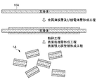
- FIG. 2 is a diagram illustrating a first manufacturing method of the infrared reflective pigment 1 according to the present embodiment.
- the first method for producing the infrared reflective pigment 1 is a step of forming a laminate 13 comprising a metal thin film layer 11 and a dielectric layer 12 on a support 10 (hereinafter referred to as a metal thin film layer and a metal thin film layer).
- the metal thin film layer and dielectric layer forming step are alternately formed on one surface (upper surface in FIG. 2) of the support 10 to obtain the laminate 13.
- the support 10 may be transparent or opaque, and a metal material, a polymer material, an oxide material, glass or the like is used.
- a metal material generally used for applications such as a support is used.
- various stainless steels such as SUS304, SUS316, SUS316L, SUS420J2, SUS630, gold, platinum, silver, copper, nickel, cobalt, titanium, iron, aluminum, tin, or nickel-titanium (Ni-Ti) ) Alloys, nickel-cobalt (Ni—Co) alloys, cobalt-chromium (Co—Cr) alloys, various alloys such as zinc-tungsten (Zn—W) alloys, inorganic materials such as various ceramic materials, and metal-ceramics A composite etc. are mentioned. These may be used individually by 1 type and may use 2 or more types together.
- polyester films As the polymer material, various resin films can be used. Specific examples include polyolefin films (polyethylene, polypropylene, etc.), polyester films (polyethylene terephthalate, polyethylene naphthalate, etc.), polyvinyl chloride, cellulose triacetate, water-soluble films (naturally occurring starch, gelatin, semi-synthetic carboxy From cellulose derivatives such as methylcellulose (CMC) and methylcellulose (MC), polyvinyl alcohol (PVA), polyacrylic acid polymer, polyacrylamide (PAM), polyethylene oxide (PEO)), etc. can be used, preferably polyester film A water-soluble film is used.
- the polyester film (hereinafter referred to as “polyester”) is preferably a polyester having film-forming properties having a dicarboxylic acid component and a diol component as main components.
- polyesters terephthalic acid and 2,6-naphthalenedicarboxylic acid are preferable as the dicarboxylic acid component from the viewpoint of transparency, mechanical strength, dimensional stability, and the like, and ethylene glycol and 1,4- Polyester having cyclohexanedimethanol as a main constituent is preferred.
- polyesters mainly composed of polyethylene terephthalate and polyethylene naphthalate, copolymerized polyesters composed of terephthalic acid, 2,6-naphthalenedicarboxylic acid and ethylene glycol, and mixtures of two or more of these polyesters are mainly used. Polyester as a constituent component is preferable.
- titanium dioxide aluminum oxide, zirconium oxide, silicon dioxide or the like is used.
- the thickness of the support 10 is preferably 0.01 to 10 mm, more preferably 0.05 to 5 mm.
- the support 10 may be a stack of two or more. At this time, the type of the support 10 may be the same or different.
- a release layer made of an acrylate copolymer resin on the surface of the support 10.
- the release layer may be formed by a conventionally known method, for example, a bar coater method, a dipping method, a spin coater method, a spray method, or the like.
- the metal thin film layer 11 and the dielectric layer 12 are supported by chemical vapor deposition (CVD), sputtering, solution coating, electron beam evaporation (EB), ion plating, dipping, spraying, etc., respectively. Formed on the body 10.
- CVD chemical vapor deposition
- sputtering sputtering
- solution coating sputtering
- EB electron beam evaporation
- ion plating dipping, spraying, etc.
- the laminate 13 having the metal thin film layer 11 and the dielectric layer 12 can be formed under a conventionally known condition.
- a metal-containing solution containing the constituent material of the metal thin film layer 11 and a dielectric-containing solution containing the constituent material of the dielectric layer 12 are prepared, and these are alternately applied and dried, whereby the metal thin film layer 11 and the dielectric layer 12 can be formed.
- the coating method include a roll coating method, a rod bar coating method, an air knife coating method, a spray coating method, a slide curtain coating method, a slide hopper (slide bead) coating method, and an extrusion coating method.
- the coating amounts of the metal thin film solution and the dielectric solution are appropriately set so that the film thickness after drying falls within the preferable film thickness ranges of the metal thin film layer 11 and the dielectric layer 12 described above.
- the laminate 13 having the metal thin film layer 11 and the dielectric layer 12 is peeled from the support 10.
- the laminated body 13 can be peeled from the support body 10 by being immersed in an ultrasonic water bath as will be described later.
- the laminate 13 formed on the support 10 can be easily peeled by providing a release layer on the surface of the support 10. .
- the support 10 is dissolved by simply immersing in water, and the laminate 13 can be easily peeled off.
- the laminate 13 having the metal thin film layer 11 and the dielectric layer 12 peeled from the support 10 is pulverized to a desired size.
- the pulverization method for example, mechanical pulverization using a pulverizer, wet pulverization using a vibration mill, ball mill, jet mill, or the like, or dry pulverization is used.
- the solvent may be any solvent that does not dissolve the constituents of the laminate 13, such as water; alcohols such as methanol, ethanol, isopropanol, n-butyl alcohol, t-butyl alcohol, and ethylene glycol.
- Ketones such as acetone and methyl ethyl ketone; esters such as ethyl acetate; halides such as chloroform and methylene chloride; olefins such as butane and hexane; ethers such as tetrahydrofuran (THF), butyl ether and dioxane; benzene, xylene, Aromatics such as toluene; amides such as N, N-dimethylformamide (DMF) and dimethylacetamide (DMAc); and a mixed solvent thereof may be used.
- the laminate 13 When pulverizing with a dry method, the laminate 13 may be cooled with liquid nitrogen or the like to obtain a hard state and then pulverized.
- a pulverization method in an ultrasonic water bath may be used.
- the laminate 13 formed on the support 10 is immersed in an ultrasonic water bath so that the laminate 13 is peeled off from the support 10 and then the peeled laminate 13 is pulverized with ultrasonic waves. To do.
- a classification method a conventionally known dry classifier or the like is used.
- a sieving machine using a sieve net a gravity classifier that classifies coarse particles and fine powders by the difference between the settling speed and the upflow speed by a horizontal flow type or an upflow type, etc., and sedimentation of particles in a centrifugal force field.
- Centrifugal classifiers to be used, inertia classifiers for classifying particles with large inertia by changing the direction of the air flow including particles to remove them from the streamline, and the like are used.
- the number average particle diameter D 50 is preferably 0.5 to 50 ⁇ m, and more preferably 1 to 20 ⁇ m.
- the number average particle diameter D 50 can be measured by, for example, an image analysis method using a flow particle image analyzer “FPIA-3000”.
- the obtained infrared reflective pigment 1 is preferably subjected to a surface treatment layer forming step after the pulverization step, and more preferably a surface tension adjusting layer forming step.
- the surface treatment layer 14 covering the entire surface is formed on the surface of the infrared reflective pigment 1 crushed in the pulverization step.
- the method for forming the surface treatment layer 14 include a heat decomposition method, a neutralization hydrolysis method, and a sol-gel method. By these methods, the surface treatment layer 14 is uniformly formed on the end surface portion of the laminate 13, and the entire surface of the infrared reflective pigment 1 can be covered with the surface treatment layer 14.
- the infrared reflective pigment 1 obtained by pulverization is dispersed in distilled water to prepare a slurry, and an aqueous sodium aluminate solution is added to the slurry. Throughout the addition, the pH of the slurry is maintained at about 6.5 by adding sulfuric acid. After the addition of the sodium aluminate aqueous solution is completed, the infrared reflective pigment 1 having the entire surface coated with the surface treatment layer 14 made of aluminum oxide is obtained by filtering off and washing with water. In the sol-gel method, a solution such as an organometallic compound is hydrolyzed and polycondensed to form a sol, which is then gelled. Then, the surface treatment layer 14 made of a metal oxide is obtained by heating.
- the surface tension adjusting layer 15 is formed on the surface of the infrared reflective pigment 1 covered with the surface treatment layer 14.
- a conventionally known dipping method is used. Specifically, for example, the laminate 13 on which the surface treatment layer 14 is formed is dispersed in a solution containing stearic acid and petroleum distillate, and is processed in an ultrasonic bath. The dispersion is then filtered with suction, washed with solvent and dried. Thereby, the surface tension adjustment layer 15 which coat
- FIG. 3 is a diagram illustrating a second manufacturing method of the infrared reflective pigment 1 according to the present embodiment.
- the second manufacturing method of the infrared reflective pigment 1 is a step of obtaining a laminate 13 by forming a metal thin film layer and a dielectric layer on a support 10A (hereinafter referred to as a metal thin film layer). And a dielectric layer forming step) and a step of pulverizing the laminate 13 including the support 10A (hereinafter referred to as a pulverization step).
- the second manufacturing method is different from the first manufacturing method in that the peeling step is not provided and the support 10 ⁇ / b> A constitutes a part of the infrared reflective pigment 1.
- a transparent material among the materials listed in the first manufacturing method is used. Specifically, a transparent material made of titanium dioxide, aluminum oxide, tin oxide, tin-added indium oxide (ITO), antimony-added tin oxide (ATO), zirconium oxide, silicon dioxide, glass or the like is used. In addition, since a peeling process is not provided, a peeling layer is unnecessary on the surface of the support 10A.
- the thickness of the support 10A is preferably 0.05 to 100 ⁇ m from the viewpoint of functioning as a thin film forming substrate in the metal thin film layer and dielectric layer forming step and being easily pulverized in the pulverizing step. 1 to 50 ⁇ m is more preferable.
- a dielectric thin plate 10a that functions as the dielectric layer 12 may be used as the support 10A.
- a transparent material that can form the dielectric layer 12 is used.
- a transparent material made of titanium dioxide, aluminum oxide, zirconium oxide, silicon dioxide or the like is used.
- the thickness of the dielectric thin plate 10a is a thickness that satisfies the thickness condition of the support 10A and functions as the dielectric layer 12. Specifically, when the wavelength of incident light in the visible light peripheral region is ⁇ and the refractive index of the dielectric thin plate 10a is n, the thickness of the dielectric thin plate 10a is an integer multiple of ⁇ / 4n ⁇ 10 nm. .
- the metal thin film layer 11 and the dielectric layer 12 are formed on both surfaces of the support 10A in the metal thin film layer and dielectric layer forming step.
- the formation method itself of the metal thin film layer 11 and the dielectric layer 12 is the same as the first manufacturing method.
- the dielectric layer 12 is formed.
- a laminate 13 is obtained in which the third dielectric layer 12 in the middle of the five-layer structure of the laminate 13 shown in FIG. 1 is configured by the support 10A.
- the metal thin film layer and the dielectric layer are formed on both sides of the support 10A, but may be formed only on one side.
- the laminated body 13 obtained is pulverized, whereby the infrared reflective pigment 1A can be obtained.
- the infrared reflective pigment 1A is preferably subjected to a surface treatment layer forming step after the pulverization step, and further preferably a surface tension adjusting layer forming step.
- the crushing step, the surface treatment layer forming step, and the surface tension adjusting layer forming step are the same as in the first manufacturing method.
- the infrared reflective coating composition according to this embodiment is a coating composition containing the above-described infrared reflective pigment 1.
- the infrared reflective coating composition according to this embodiment contains the above-described infrared reflective pigment 1 and a resin component as main components.
- the paint type include organic solvent-type paints, NAD systems, water-based paints, emulsion paints, colloidal paints, powder paints, and the like.
- the infrared reflective coating composition according to the present embodiment is produced by a conventionally known method.
- the content of the infrared reflective pigment 1 in the infrared reflective coating composition according to the present embodiment is preferably such that the pigment surface density is 100 to 300%.
- WCA represents the water surface diffusion area per gram, and is determined according to a method based on JIS-K5906: 1998.
- a solvent such as a solvent can be appropriately selected in consideration of the coating method, film forming conditions, solubility in the support, and the like.
- alcohols such as methanol, ethanol, 2-propanol, 1-butanol; ethyl acetate, butyl acetate, isobutyl acetate, ethyl propionate, ethylene glycol monomethyl ether acetate, propylene glycol monomethyl ether acetate, propylene glycol monoethyl ether acetate, etc.
- Glycol derivatives such as formamide, N-methylformamide, dimethylformamide (DMF), dimethylacetamide, dimethylsulfoxide (DMSO), N-methylpyrrolidone (NMP); acetone, methyl ethyl ketone (MEK), methylpropyl ketone, Ketones such as methyl isobutyl ketone, acetylacetone, and cyclohexanone; benzene derivatives such as toluene, xylene, mesitylene, and dodecylbenzene; halogen solvents such as chloroform and dichloromethylene;
- the resin component examples include (a) acrylic resin, (b) polyester resin, (c) alkyd resin, (d) fluororesin, (e) epoxy resin, (f) polyurethane resin, (g) polyether resin, and the like. These may be used alone or in combination of two or more.
- acrylic resins and polyester resins are preferably used from the viewpoint of weather resistance and adhesion.
- Acrylic resin the copolymer of an acryl-type monomer and another ethylenically unsaturated monomer can be mentioned.
- Acrylic monomers that can be used in the copolymer include acrylic acid or methacrylic acid methyl, ethyl, propyl, n-butyl, i-butyl, t-butyl, 2-ethylhexyl, lauryl, phenyl, benzyl, 2-hydroxy Esterified products such as ethyl and 2-hydroxypropyl, ring-opening adducts of caprolactone of acrylic acid or 2-hydroxyethyl methacrylate, acrylic acid or glycidyl methacrylate, acrylamide, methacrylamide and N-methylolacrylamide, polyhydric alcohol (Meth) acrylic acid ester and the like.
- the ethylenically unsaturated monomer include styrene, ⁇ -methylstyrene, itaconic acid,
- a saturated polyester resin and an unsaturated polyester resin can be mentioned, Specifically, the condensate obtained by heat-condensing a polybasic acid and a polyhydric alcohol can be mentioned, for example.
- the polybasic acid include saturated polybasic acids and unsaturated polybasic acids.
- the saturated polybasic acid include phthalic anhydride, terephthalic acid, succinic acid, and the like.
- the basic acid include maleic acid, maleic anhydride, fumaric acid and the like.
- the polyhydric alcohol include dihydric alcohol and trihydric alcohol. Examples of the dihydric alcohol include ethylene glycol and diethylene glycol. Examples of the trihydric alcohol include glycerin. And trimethylolpropane.
- alkyd resin examples include modifiers such as the above-mentioned polybasic acids and polyhydric alcohols, oils and fats and fatty acids (soybean oil, linseed oil, coconut oil, stearic acid, etc.), natural resins (rosin, succinic acid, etc.) An alkyd resin obtained by reacting can be used.
- a fluororesin any one of vinylidene fluoride resin and tetrafluoroethylene resin, or a mixture thereof, a monomer comprising a fluoroolefin and a hydroxy group-containing polymerizable compound and other copolymerizable vinyl compounds Examples thereof include resins made of various fluorine-based copolymers obtained by copolymerizing.
- bisphenol examples include bisphenol A and F.
- Examples of the bisphenol type epoxy resin include Epicoat 828, Epicoat 1001, Epicoat 1004, Epicoat 1007, and Epicoat 1009.
- polyurethane resin resin which has a urethane bond obtained by various polyol components, such as an acryl, polyester, polyether, a polycarbonate, and a polyisocyanate compound can be mentioned.
- polyisocyanate compound examples include 2,4-tolylene diisocyanate (2,4-TDI), 2,6-tolylene diisocyanate (2,6-TDI), and mixtures thereof (TDI), diphenylmethane-4, 4 ′.
- the polyether resin is a polymer or copolymer having an ether bond, such as a polyoxyethylene-based polyether, a polyoxypropylene-based polyether, or a polyoxybutylene-based polyether, or bisphenol A or bisphenol F.
- polyether resins having at least two hydroxyl groups per molecule such as polyethers derived from aromatic polyhydroxy compounds such as
- the polyether resin reacts with polyvalent carboxylic acids such as succinic acid, adipic acid, sebacic acid, phthalic acid, isophthalic acid, terephthalic acid, trimellitic acid, or reactive derivatives such as these acid anhydrides.
- a carboxyl group-containing polyether resin obtained by the above process.
- the resin component described above includes a curing type and a lacquer type, and any of them may be used.
- the curing type it is used by mixing with a crosslinking agent such as an amino resin, a (block) polyisocyanate compound, an amine, a polyamide, or a polyvalent carboxylic acid, and the curing reaction proceeds by heating or at room temperature.
- a crosslinking agent such as an amino resin, a (block) polyisocyanate compound, an amine, a polyamide, or a polyvalent carboxylic acid
- a lacquer type resin component and a cured type resin component can be used in combination.
- the infrared reflective coating composition according to this embodiment preferably has a coating solid content (NV) of 1 to 90% by mass during coating.
- NV coating solid content
- the infrared reflective pigment can be arranged in a high orientation, that is, parallel to the surface to be coated, with the shrinkage of the coating film in the drying step after painting, High infrared reflectivity and high visible light transmittance can be obtained.
- a more preferable coating solid content is 1 to 60% by mass.
- the infrared reflective coating composition according to the present embodiment includes an anti-sagging agent, a viscosity adjusting agent, an anti-settling agent, a crosslinking accelerator, a curing agent, a leveling agent, a surface adjusting agent, an antifoaming agent, a plasticizer, and an antiseptic.
- an anti-sagging agent e.g., a viscosity adjusting agent, an anti-settling agent, a crosslinking accelerator, a curing agent, a leveling agent, a surface adjusting agent, an antifoaming agent, a plasticizer, and an antiseptic.
- an anti-sagging agent e.g., fungicides, UV stabilizers and the like.
- An infrared reflective coating film can be obtained by applying the obtained infrared reflective coating composition.
- the coating method is not limited.
- painting may be performed with a brush, a spray, or a roller.
- the paint solid content at the time of coating is adjusted, and the infrared reflective pigment of the present invention is highly oriented by shrinking the infrared reflective coating film. It is preferable to arrange them in the same manner.
- the film thickness of the infrared reflective coating film is preferably 0.5 to 100 ⁇ m, more preferably 1 to 50 ⁇ m in terms of dry film thickness. If it is less than 0.5 ⁇ m, the convection associated with solvent evaporation at the time of drying is weak and the pigment is difficult to orient on the coating film surface. When it exceeds 100 ⁇ m, coating film defects such as sagging and flares tend to occur.
- the drying step after applying the infrared reflective coating composition is preferably 60 to 200 ° C., more preferably 80 to 160 ° C. from the viewpoint of arranging the infrared reflective pigment of the present invention in a highly oriented manner.
- the obtained infrared reflective coating film is not only excellent in infrared reflectivity but also extremely excellent in visible light transmittance.
- About the solar radiation acquisition rate, 0.7 or less is used as an evaluation standard as a standard with a low heat shielding effect and insufficient heat shielding performance. That is, the solar radiation acquisition rate is preferably 0.7 or less, and more preferably 0.6 or less.
- the visible light transmittance 70% or more defined as a safety standard for automobile windshields is used as an evaluation standard. That is, the visible light transmittance is preferably 70% or more, and more preferably 80% or more.
- the measurement of the visible light transmittance and the solar radiation acquisition rate can be carried out according to a method in accordance with JIS-R3106: 1998 “Testing method of transmittance, reflectance, emissivity, solar heat acquisition rate of plate glass”.
- Examples 1 to 13, Comparative Examples 1 to 4 According to the formulation shown in Table 1, infrared reflective coating compositions of Examples 1 to 13 and Comparative Examples 1 to 4 were prepared. In Examples 1 to 3, 5 to 11, 13 and Comparative Examples 1 to 4, the infrared reflective pigment 1 was prepared by the above-described first manufacturing method, and Examples 4 and 12 were prepared by the above-described second manufacturing method. Infrared reflective pigment 1A was prepared.
- the laminated body 13 was formed by alternately forming the dielectric layers or metal thin film layers shown in Table 1 from the first layer to the maximum seventh layer on the release layer.
- the dielectric layer and the metal thin film layer were formed by an electron beam method using a vacuum deposition apparatus (model number: EX-200) manufactured by ULVAC.
- the laminate 13 was immersed in acetone for 30 minutes to dissolve and peel the release layer, followed by ultrasonic grinding to obtain an infrared reflective pigment having a number average particle diameter D 50 of 5 ⁇ m.
- the infrared reflective pigment obtained as described above was filtered by suction, and then placed in distilled water, adjusted to 45 to 70 ° C., and stirred with sodium aluminate so as to be 4% by mass with respect to the pigment. added. At that time, sulfuric acid was used to maintain the pH of the slurry at 6-9. The infrared reflective pigment on which the surface treatment layer of aluminum oxide was formed was filtered, washed and dried.
- the infrared reflective pigment on which the surface treatment layer was formed was further immersed in ethyl acetate to which 3% by mass of stearic acid was added and subjected to ultrasonic treatment to form the surface tension adjusting layer 15. In this way, an infrared reflective pigment 1 was obtained.
- Example 1A Production of Infrared Reflective Pigment 1A (Examples 4 and 12)> As in the case of Example 1, except that a natural mica plate (manufactured by Yamaguchi Mica Co., Ltd.) of 50 mm ⁇ 50 mm ⁇ 0.5 ⁇ m was used as the support 10A, and a dielectric layer and a metal layer were provided on both sides of the substrate. Infrared reflective pigment 1A was obtained.
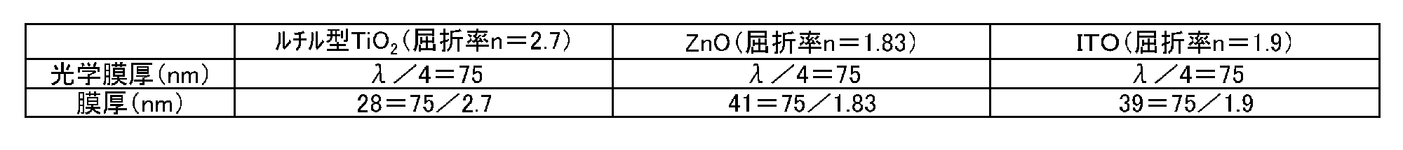
- ⁇ Thickness of dielectric layer and metal thin film layer> the dielectric layer and the metal thin film layer were formed so that the wavelength ⁇ of incident light in the visible light peripheral region was 300 nm and the film thicknesses shown in Table 1 were obtained. Specifically, the optical film thickness and actual film thickness of titanium dioxide (rutile type), zinc oxide, and ITO used for the dielectric layer are as shown in Table 2 below. The optical film thicknesses of the other dielectric layers and metal thin film layers were similarly calculated by calculating ⁇ / 4 so as to be an integral multiple of ⁇ / 4 ⁇ 10 nm. The film thickness was controlled by a crystal oscillation type film forming controller (“CRTM-6000G” manufactured by ULVAC).
- CRTM-6000G crystal oscillation type film forming controller
- each infrared reflective coating composition having a coating solid content of 40% by mass was obtained.
- the WCA of the infrared reflective pigments of the examples and comparative examples is as shown in Table 1.
- the specific gravity of the coating film is 1.4 (g / cm 3 )
- the film thickness was 30 ⁇ m (30 ⁇ 10 ⁇ 4 cm).
- each infrared reflective coating composition was applied to the glass plate using an 8 MIL applicator.
- the coating amount was adjusted so that the coating thickness after drying was 30 ⁇ m.
- the mixture was allowed to stand at room temperature for 10 minutes and then dried at 110 ° C. for 15 minutes. Thereby, each infrared reflective coating film was obtained.
- Examples 1 to 6, 10 to 12 having a surface treatment layer had superior weather resistance compared to Examples 7 to 9 and 13 having no surface treatment layer. From this result, according to the infrared reflective pigment of the present invention that covers the surface of the laminate and has a surface treatment layer made of an oxide, it is confirmed that deterioration of the resin can be suppressed and excellent weather resistance can be obtained. It was done.
- Examples 1 to 8, 10 to 13 having a surface tension adjusting layer can obtain a higher visible light transmittance than Example 9 having no surface tension adjusting layer. From this result, it was confirmed that according to the infrared reflective pigment of the present invention further covering the surface of the surface treatment layer and further comprising a surface tension adjusting layer made of a surface tension adjusting agent, higher visible light transmittance can be obtained. It was done.
Abstract
Description
[赤外反射性顔料]
本実施形態に係る赤外反射性顔料は、高い赤外光反射性と高い可視光透過性を兼ね備えた鱗片状(扁平状)の顔料である。本実施形態に係る赤外反射性顔料は、塗膜中に配合されたときに、塗膜面に対してその扁平面が平行になるように配向することで、より高い赤外反射性と高い可視光透過性を発現する。
本実施形態に係る赤外反射性顔料は、少なくとも1層の金属薄膜層と、少なくとも2層の透明な誘電体層と、を有する積層体を備える。 Hereinafter, embodiments of the present invention will be described in detail with reference to the drawings.
[Infrared reflective pigment]
The infrared reflective pigment according to the present embodiment is a scaly (flat) pigment having both high infrared light reflectivity and high visible light transmittance. When the infrared reflective pigment according to the present embodiment is blended in the coating film, the infrared reflecting pigment is oriented so that its flat surface is parallel to the coating film surface. Visible light transmission is expressed.
The infrared reflective pigment according to the present embodiment includes a laminate having at least one metal thin film layer and at least two transparent dielectric layers.
なお、本実施形態に係る赤外反射性顔料1の積層体13は、図1に示す5層構造に限定されず、少なくとも1層の金属薄膜層11と、少なくとも2層の透明な誘電体層12とを有していればよく、層数は限定されないが、金属薄膜層11と誘電体層12が交互に積層されていることが好ましい。 FIG. 1 is a schematic diagram showing a cross-sectional structure of an infrared reflective pigment according to this embodiment. In FIG. 1, as an example of the infrared reflective pigment according to the present embodiment, there are a total of five layers of two metal
The laminated
以下、金属薄膜層11、誘電体層12、表面処理層14及び表面張力調整層15の各層の構成について、詳細に説明する。 Further, as shown in FIG. 1, the infrared reflective pigment 1 according to the present embodiment includes a surface treatment layer 14 that covers the surface of the
Hereinafter, the configuration of each of the metal
なお、金属薄膜層11を複数層有する場合、製造上の観点からは各金属薄膜層11を同一の材料から構成することが好ましいが、各金属薄膜層11を異なる材料から構成してもよい。 The metal
In addition, when it has multiple metal
なお、製造上の観点から各誘電体層12を同一の材料から構成することが好ましいが、各誘電体層12を異なる材料から構成してもよい。 The
In addition, although it is preferable that each
ここで、可視光周辺域の波長は、可視光域である380~780nm及びその周辺域であり、具体的には180~980nmが該当する。屈折率nは、例えばHORIBA製やJ.A.Woolam JAPAN製のエリプソメータにより測定可能である。
具体的には、例えば図1に示す5層構造の赤外反射性顔料1では、中央に配置された誘電体層12の膜厚はλ/2n(光学膜厚はλ/2)であり、最も外側に配置された2つの誘電体層12の膜厚はλ/4n(光学膜厚はλ/4)である。 The optical film thickness of the
Here, the wavelength of the visible light peripheral region is the visible light region of 380 to 780 nm and its peripheral region, and specifically corresponds to 180 to 980 nm. The refractive index n is, for example, made by HORIBA or J.A. A. It can be measured with an ellipsometer manufactured by Woolam Japan.
Specifically, for example, in the infrared reflective pigment 1 having a five-layer structure shown in FIG. 1, the film thickness of the
[第1製造方法]
図2は、本実施形態に係る赤外反射性顔料1の第1製造方法を示す図である。図2に示すように、赤外反射性顔料1の第1製造方法は、支持体10上に金属薄膜層11及び誘電体層12からなる積層体13を形成する工程(以下、金属薄膜層及び誘電体層形成工程という)と、当該積層体13を支持体10から剥離する工程(以下、剥離工程という)と、当該積層体13を粉砕する工程(以下、粉砕工程という)と、を有する。 Next, the manufacturing method of the infrared reflective pigment 1 which concerns on this embodiment is demonstrated.
[First production method]
FIG. 2 is a diagram illustrating a first manufacturing method of the infrared reflective pigment 1 according to the present embodiment. As shown in FIG. 2, the first method for producing the infrared reflective pigment 1 is a step of forming a laminate 13 comprising a metal
支持体10としては、透明でも不透明でもよく、金属材料、高分子材料、酸化物材料、ガラス等が用いられる。 First, in the metal thin film layer and dielectric layer forming step, the metal thin film layer and the dielectric layer are alternately formed on one surface (upper surface in FIG. 2) of the
The
塗布方法としては、例えば、ロールコーティング法、ロッドバーコーティング法、エアナイフコーティング法、スプレーコーティング法、スライド型カーテン塗布法、スライドホッパー(スライドビード)塗布法、エクストルージョンコート法等が挙げられる。
金属薄膜溶液及び誘電体溶液の塗布量は、乾燥後の膜厚が上述の金属薄膜層11及び誘電体層12の各層の好ましい膜厚の範囲内となるように、適宜設定される。 As the solution coating method, a metal-containing solution containing the constituent material of the metal
Examples of the coating method include a roll coating method, a rod bar coating method, an air knife coating method, a spray coating method, a slide curtain coating method, a slide hopper (slide bead) coating method, and an extrusion coating method.
The coating amounts of the metal thin film solution and the dielectric solution are appropriately set so that the film thickness after drying falls within the preferable film thickness ranges of the metal
例えば、後述するように超音波水浴中に浸漬させることにより、支持体10から積層体13を剥離することができる。上述したように、支持体10として水溶性フィルム以外の材料を用いた場合には、支持体10の表面に剥離層を設けることで、支持体10上に形成した積層体13を容易に剥離できる。また、支持体10として水溶性フィルムを用いた場合には、水中に浸漬するだけで支持体10が溶解し、容易に積層体13を剥離することができる。 Next, in the peeling step, the laminate 13 having the metal
For example, the
粉砕方法としては、例えば、粉砕機による機械的粉砕、振動ミル、ボールミル、ジェットミル等を用いた湿式粉砕、乾式粉砕が用いられる。湿式粉砕する場合、溶媒としては、積層体13の構成成分が溶解しない溶媒であればよく、例えば、水;メタノール、エタノール、イソプロパノール、n-ブチルアルコール、t-ブチルアルコール、エチレングリコール等のアルコール類;アセトン、メチルエチルケトン等のケトン類;酢酸エチル等のエステル類;クロロホルム、塩化メチレン等のハロゲン化物;ブタン、ヘキサン等のオレフィン類;テトラヒドロフラン(THF)、ブチルエーテル、ジオキサン等のエーテル類;ベンゼン、キシレン、トルエン等の芳香族類;N,N-ジメチルホルムアミド(DMF)、ジメチルアセトアミド(DMAc)等のアミド類;及びこれらの混合溶媒であってもよい。乾式で粉砕する際には、積層体13を液体窒素等で冷却して、硬い状態としてから粉砕してもよい。 Next, in the pulverization step, the laminate 13 having the metal
As the pulverization method, for example, mechanical pulverization using a pulverizer, wet pulverization using a vibration mill, ball mill, jet mill, or the like, or dry pulverization is used. In the case of wet pulverization, the solvent may be any solvent that does not dissolve the constituents of the laminate 13, such as water; alcohols such as methanol, ethanol, isopropanol, n-butyl alcohol, t-butyl alcohol, and ethylene glycol. Ketones such as acetone and methyl ethyl ketone; esters such as ethyl acetate; halides such as chloroform and methylene chloride; olefins such as butane and hexane; ethers such as tetrahydrofuran (THF), butyl ether and dioxane; benzene, xylene, Aromatics such as toluene; amides such as N, N-dimethylformamide (DMF) and dimethylacetamide (DMAc); and a mixed solvent thereof may be used. When pulverizing with a dry method, the laminate 13 may be cooled with liquid nitrogen or the like to obtain a hard state and then pulverized.
表面処理層14の形成方法としては、例えば、加熱分解法、中和加水分解法、ゾルゲル法等が挙げられる。これらの方法により、積層体13の端面部にも均一に表面処理層14が形成され、赤外反射性顔料1の表面全体を表面処理層14で被覆できる。 In the surface treatment layer forming step, the surface treatment layer 14 covering the entire surface is formed on the surface of the infrared reflective pigment 1 crushed in the pulverization step.
Examples of the method for forming the surface treatment layer 14 include a heat decomposition method, a neutralization hydrolysis method, and a sol-gel method. By these methods, the surface treatment layer 14 is uniformly formed on the end surface portion of the laminate 13, and the entire surface of the infrared reflective pigment 1 can be covered with the surface treatment layer 14.
また、ゾルゲル法では、有機金属化合物等の溶液を加水分解・重縮合させ、ゾルを形成した後にゲル化する。その後、加熱することにより、金属酸化物からなる表面処理層14が得られる。 Specifically, for example, the infrared reflective pigment 1 obtained by pulverization is dispersed in distilled water to prepare a slurry, and an aqueous sodium aluminate solution is added to the slurry. Throughout the addition, the pH of the slurry is maintained at about 6.5 by adding sulfuric acid. After the addition of the sodium aluminate aqueous solution is completed, the infrared reflective pigment 1 having the entire surface coated with the surface treatment layer 14 made of aluminum oxide is obtained by filtering off and washing with water.
In the sol-gel method, a solution such as an organometallic compound is hydrolyzed and polycondensed to form a sol, which is then gelled. Then, the surface treatment layer 14 made of a metal oxide is obtained by heating.
表面張力調整層15の形成方法としては、従来公知の浸漬法が用いられる。具体的には、例えば、ステアリン酸と石油蒸留物を含む溶液中に、表面処理層14が形成された積層体13を分散させ、超音波バス中で処理する。次いで、分散物を吸引濾過して溶媒で洗浄した後、乾燥する。これにより、積層体13の表面に形成された表面処理層14を被覆する表面張力調整層15が得られる。 In the surface tension adjusting layer forming step, the surface tension adjusting layer 15 is formed on the surface of the infrared reflective pigment 1 covered with the surface treatment layer 14.
As a method for forming the surface tension adjusting layer 15, a conventionally known dipping method is used. Specifically, for example, the laminate 13 on which the surface treatment layer 14 is formed is dispersed in a solution containing stearic acid and petroleum distillate, and is processed in an ultrasonic bath. The dispersion is then filtered with suction, washed with solvent and dried. Thereby, the surface tension adjustment layer 15 which coat | covers the surface treatment layer 14 formed in the surface of the
図3は、本実施形態に係る赤外反射性顔料1の第2製造方法を示す図である。図3に示すように、赤外反射性顔料1の第2製造方法は、支持体10A上に、金属薄膜層及び誘電体層を形成することで積層体13を得る工程(以下、金属薄膜層及び誘電体層形成工程という)と、支持体10Aを含む積層体13を粉砕する工程(以下、粉砕工程という)と、を有する。第2製造方法は、剥離工程を設けず、支持体10Aが赤外反射性顔料1の一部を構成する点において、第1製造方法と相違する。 [Second production method]
FIG. 3 is a diagram illustrating a second manufacturing method of the infrared reflective pigment 1 according to the present embodiment. As shown in FIG. 3, the second manufacturing method of the infrared reflective pigment 1 is a step of obtaining a laminate 13 by forming a metal thin film layer and a dielectric layer on a
粉砕工程、表面処理層形成工程及び表面張力調整層形成工程は、第1製造方法と同様である。 Next, the
The crushing step, the surface treatment layer forming step, and the surface tension adjusting layer forming step are the same as in the first manufacturing method.
本実施形態に係る赤外反射性塗料組成物は、上述の赤外反射性顔料1を含有する塗料組成物である。
本実施形態に係る赤外反射性塗料組成物は、上述の赤外反射性顔料1と、樹脂成分と、を主成分として含有する。塗料タイプとしては、有機溶剤型塗料、NAD系、水性塗料、エマルション塗料、コロイダル塗料、紛体塗料等が挙げられる。本実施形態に係る赤外反射性塗料組成物は、従来公知の方法により製造される。 [Infrared reflective coating composition]
The infrared reflective coating composition according to this embodiment is a coating composition containing the above-described infrared reflective pigment 1.
The infrared reflective coating composition according to this embodiment contains the above-described infrared reflective pigment 1 and a resin component as main components. Examples of the paint type include organic solvent-type paints, NAD systems, water-based paints, emulsion paints, colloidal paints, powder paints, and the like. The infrared reflective coating composition according to the present embodiment is produced by a conventionally known method.
[数1]
顔料面密度(%)=WCA(cm2/g)×PWC(%)×塗膜比重(g/cm3)×膜厚(cm)
As the infrared reflective pigment 1, those described above are used. The content of the infrared reflective pigment 1 in the infrared reflective coating composition according to the present embodiment is preferably such that the pigment surface density is 100 to 300%. The pigment surface density (%) is the infrared rays actually contained with respect to the content that covers the coated surface without excess or deficiency in a state where the infrared reflective pigments are arranged on one surface without overlapping each other. It is a mass ratio (%) of the content of the reflective pigment. Specifically, it is calculated by the following formula.
[Equation 1]
Pigment surface density (%) = WCA (cm 2 / g) × PWC (%) × Coating specific gravity (g / cm 3 ) × film thickness (cm)
[数2]
PWC(%)=顔料/(樹脂固形分+不揮発成分(添加剤等)+顔料)
Here, WCA represents the water surface diffusion area per gram, and is determined according to a method based on JIS-K5906: 1998. PWC is calculated by the following formula.
[Equation 2]
PWC (%) = pigment / (resin solid content + nonvolatile components (additives, etc.) + Pigment)
本実施形態に係る赤外反射性塗料組成物を塗装する際、前述の通り、塗装時の塗料固形分を調整し、赤外反射性塗膜収縮により本発明の赤外反射性顔料が高配向に配列するようにすることが好ましい。 In the infrared reflective coating composition according to this embodiment, the coating method is not limited. For example, in addition to an applicator and a bar coater, painting may be performed with a brush, a spray, or a roller.
When applying the infrared reflective paint composition according to this embodiment, as described above, the paint solid content at the time of coating is adjusted, and the infrared reflective pigment of the present invention is highly oriented by shrinking the infrared reflective coating film. It is preferable to arrange them in the same manner.
赤外反射性塗料組成物を塗装した後の乾燥工程は、本発明の赤外反射性顔料を高配向に配列する観点で、60~200℃が好ましく、80~160℃がより好ましい。 The film thickness of the infrared reflective coating film is preferably 0.5 to 100 μm, more preferably 1 to 50 μm in terms of dry film thickness. If it is less than 0.5 μm, the convection associated with solvent evaporation at the time of drying is weak and the pigment is difficult to orient on the coating film surface. When it exceeds 100 μm, coating film defects such as sagging and flares tend to occur.
The drying step after applying the infrared reflective coating composition is preferably 60 to 200 ° C., more preferably 80 to 160 ° C. from the viewpoint of arranging the infrared reflective pigment of the present invention in a highly oriented manner.
可視光透過率及び日射取得率の測定は、JIS-R3106:1998「板ガラス類の透過率・反射率・放射率・日射熱取得率の試験方法」に準拠した方法に従って実施することができる。 Regarding visible light transmittance, 70% or more defined as a safety standard for automobile windshields is used as an evaluation standard. That is, the visible light transmittance is preferably 70% or more, and more preferably 80% or more.
The measurement of the visible light transmittance and the solar radiation acquisition rate can be carried out according to a method in accordance with JIS-R3106: 1998 “Testing method of transmittance, reflectance, emissivity, solar heat acquisition rate of plate glass”.
表1に示す配合に従って、実施例1~13及び比較例1~4の赤外反射性塗料組成物を調製した。実施例1~3、5~11、13及び比較例1~4は、上述の第1製造方法により赤外反射性顔料1を調製し、実施例4、12は、上述の第2製造方法により赤外反射性顔料1Aを調製した。 [Examples 1 to 13, Comparative Examples 1 to 4]
According to the formulation shown in Table 1, infrared reflective coating compositions of Examples 1 to 13 and Comparative Examples 1 to 4 were prepared. In Examples 1 to 3, 5 to 11, 13 and Comparative Examples 1 to 4, the infrared reflective pigment 1 was prepared by the above-described first manufacturing method, and Examples 4 and 12 were prepared by the above-described second manufacturing method. Infrared
先ず、支持体10として、50×50×2mmのガラス板(TP技研製)に、アクリル樹脂(アクリディック A-1371 DIC社製)を酢酸ブチルを用いて10質量%(固形分換算)となるように調製した後、スピンコーターにて乾燥膜厚が1μmとなるように塗布した。その後、80℃で15分間乾燥し、剥離層を形成した。 <First Production Method: Production of Infrared Reflective Pigment 1 (Examples 1 to 3, 5 to 11, 13 and Comparative Examples 1 to 4)>
First, as a
支持体10Aとして、50mm×50mm×0.5μmの天然マイカ板(ヤマグチマイカ社製)を用い、基材の両面に、誘電体層及び金属層を設けたこと以外は、実施例1と同様にし、赤外反射性顔料1Aを得た。 <Second Production Method: Production of Infrared
As in the case of Example 1, except that a natural mica plate (manufactured by Yamaguchi Mica Co., Ltd.) of 50 mm × 50 mm × 0.5 μm was used as the
実施例1~13及び比較例1~4では、可視光周辺域の入射光の波長λを300nmとし、表1に示した膜厚となるように、誘電体層及び金属薄膜層を形成した。
具体的には、誘電体層に用いた二酸化チタン(ルチル型)、酸化亜鉛及びITOの光学膜厚と実際の膜厚は、以下の表2に示した通りである。他の誘電体層及び金属薄膜層の光学膜厚も、同様にλ/4を算出してλ/4の整数倍±10nmとなるようにして、実際の膜厚を設定した。
なお、膜厚制御は、水晶発振式製膜コントローラ(アルバック社製「CRTM-6000G」)にて行った。 <Thickness of dielectric layer and metal thin film layer>
In Examples 1 to 13 and Comparative Examples 1 to 4, the dielectric layer and the metal thin film layer were formed so that the wavelength λ of incident light in the visible light peripheral region was 300 nm and the film thicknesses shown in Table 1 were obtained.
Specifically, the optical film thickness and actual film thickness of titanium dioxide (rutile type), zinc oxide, and ITO used for the dielectric layer are as shown in Table 2 below. The optical film thicknesses of the other dielectric layers and metal thin film layers were similarly calculated by calculating λ / 4 so as to be an integral multiple of λ / 4 ± 10 nm.
The film thickness was controlled by a crystal oscillation type film forming controller (“CRTM-6000G” manufactured by ULVAC).
各実施例及び比較例の赤外反射性塗膜について、可視光透過率及び日射取得率の測定を実施した。可視光透過率及び日射取得率の測定は、JIS-R3106:1998「板ガラス類の透過率・反射率・放射率・日射熱取得率の試験方法」に準拠した方法に従って実施した。測定に用いた分光光度装置は、島津製作所社製の分光光度計(型番:UV3600)であった。結果を表1に示した。 [Visible light transmittance, solar radiation acquisition rate]
About the infrared reflective coating film of each Example and a comparative example, the measurement of the visible light transmittance | permeability and the solar radiation acquisition rate was implemented. The measurement of the visible light transmittance and the solar radiation acquisition rate was carried out in accordance with JIS-R3106: 1998 “Testing method of transmittance, reflectance, emissivity, solar heat acquisition rate of plate glass”. The spectrophotometer used for the measurement was a spectrophotometer (model number: UV3600) manufactured by Shimadzu Corporation. The results are shown in Table 1.
各実施例及び比較例の赤外反射性塗膜について、超促進耐候性(SUV)試験を実施した。試験後の塗膜を、目視にて劣化度合いを評価した。試験条件及び評価基準は以下の通りとした。結果を表1に示した。
(試験条件)
測定試験機:サンシャインウェザーメーター「S80-B-H」
光照射強度:850W/cm2
照射時間:600時間
(評価基準)
3:外観上、問題が無い。
2:塗膜外観が若干白ボケて半透明であり、やや劣化が見られる。
1:塗膜外観が白ボケて透明性が失われており、劣化が見られる。 [Weatherability]
A super accelerated weather resistance (SUV) test was performed on the infrared reflective coating films of each of the examples and comparative examples. The degree of deterioration of the coated film after the test was visually evaluated. Test conditions and evaluation criteria were as follows. The results are shown in Table 1.
(Test conditions)
Measurement tester: Sunshine weather meter “S80-BH”
Light irradiation intensity: 850 W / cm 2
Irradiation time: 600 hours (evaluation criteria)
3: There is no problem in appearance.
2: The appearance of the coating film is slightly white blurred and translucent, and somewhat deteriorated.
1: The appearance of the coating film is white and the transparency is lost, and deterioration is observed.

10,10A…支持体
11…金属薄膜層
12…誘電体層
13…積層体
14…表面処理層
15…表面張力調整層 DESCRIPTION OF
Claims (8)
- 鱗片状の赤外反射性顔料であって、
少なくとも1層の金属薄膜層と、少なくとも2層の透明な誘電体層と、を有する積層体を備え、
可視光周辺域の入射光の波長をλとし且つ前記誘電体層の屈折率をnとしたときに、前記誘電体層の膜厚が(λ/4nの整数倍)±10nmであることを特徴とする赤外反射性顔料。 Scaly infrared reflective pigment,
A laminate having at least one metal thin film layer and at least two transparent dielectric layers;
The thickness of the dielectric layer is ± 10 nm (integer multiple of λ / 4n) where λ is the wavelength of incident light in the peripheral region of visible light and n is the refractive index of the dielectric layer. Infrared reflective pigment. - 前記金属薄膜層が、銀、アルミニウム、銅、金、パラジウム、亜鉛、チタン、クロム及び珪素からなる群より選択される少なくとも1種からなることを特徴とする請求項1に記載の赤外反射性顔料。 2. The infrared reflectiveness according to claim 1, wherein the metal thin film layer is made of at least one selected from the group consisting of silver, aluminum, copper, gold, palladium, zinc, titanium, chromium and silicon. Pigments.
- 前記誘電体層が、二酸化チタン、酸化亜鉛、酸化アルミニウム、酸化ジルコニウム、二酸化ケイ素、酸化錫、錫添加酸化インジウム及びアンチモン添加酸化錫からなる群より選択される少なくとも1種からなることを特徴とする請求項1又は2に記載の赤外反射性顔料。 The dielectric layer is made of at least one selected from the group consisting of titanium dioxide, zinc oxide, aluminum oxide, zirconium oxide, silicon dioxide, tin oxide, tin-doped indium oxide, and antimony-doped tin oxide. The infrared reflective pigment according to claim 1 or 2.
- 前記積層体の表面を被覆し且つ酸化物からなる表面処理層をさらに備えることを特徴とする請求項1から3いずれかに記載の赤外反射性顔料。 The infrared reflective pigment according to any one of claims 1 to 3, further comprising a surface treatment layer made of an oxide that covers the surface of the laminate.
- 前記表面処理層が、酸化アルミニウム、シリカ及び酸化ジルコニウムからなる群より選択される少なくとも1種からなることを特徴とする請求項4に記載の赤外反射性顔料。 The infrared reflective pigment according to claim 4, wherein the surface treatment layer comprises at least one selected from the group consisting of aluminum oxide, silica and zirconium oxide.
- 前記表面処理層の表面を被覆し且つ表面張力調整剤からなる表面張力調整層をさらに備えることを特徴とする請求項4又は5に記載の赤外反射性顔料。 The infrared reflective pigment according to claim 4 or 5, further comprising a surface tension adjusting layer that covers the surface of the surface treatment layer and is made of a surface tension adjusting agent.
- 前記表面張力調整層が、ステアリン酸を含む表面張力調整剤からなることを特徴とする請求項6に記載の赤外反射性顔料。 The infrared reflective pigment according to claim 6, wherein the surface tension adjusting layer comprises a surface tension adjusting agent containing stearic acid.
- 請求項1から7いずれかに記載の赤外反射性顔料を含有する赤外反射性塗料組成物。 An infrared reflective coating composition containing the infrared reflective pigment according to any one of claims 1 to 7.
Priority Applications (5)
| Application Number | Priority Date | Filing Date | Title |
|---|---|---|---|
| SG11201700175PA SG11201700175PA (en) | 2014-07-10 | 2015-07-09 | Infrared-reflective pigment and infrared-reflective coating composition |
| US15/324,159 US10131790B2 (en) | 2014-07-10 | 2015-07-09 | Infrared-reflective pigment and infrared-reflective coating composition |
| CN201580037546.7A CN106574129B (en) | 2014-07-10 | 2015-07-09 | Infrared reflecting paint and infrared reflective coating composition |
| EP15818518.1A EP3168266A4 (en) | 2014-07-10 | 2015-07-09 | Infrared-reflective pigment and infrared-reflective coating composition |
| JP2016532971A JP6162901B2 (en) | 2014-07-10 | 2015-07-09 | Infrared reflective pigment and infrared reflective coating composition |
Applications Claiming Priority (2)
| Application Number | Priority Date | Filing Date | Title |
|---|---|---|---|
| JP2014142719 | 2014-07-10 | ||
| JP2014-142719 | 2014-07-10 |
Publications (1)
| Publication Number | Publication Date |
|---|---|
| WO2016006664A1 true WO2016006664A1 (en) | 2016-01-14 |
Family
ID=55064292
Family Applications (1)
| Application Number | Title | Priority Date | Filing Date |
|---|---|---|---|
| PCT/JP2015/069794 WO2016006664A1 (en) | 2014-07-10 | 2015-07-09 | Infrared-reflective pigment and infrared-reflective coating composition |
Country Status (6)
| Country | Link |
|---|---|
| US (1) | US10131790B2 (en) |
| EP (1) | EP3168266A4 (en) |
| JP (1) | JP6162901B2 (en) |
| CN (1) | CN106574129B (en) |
| SG (1) | SG11201700175PA (en) |
| WO (1) | WO2016006664A1 (en) |
Cited By (12)
| Publication number | Priority date | Publication date | Assignee | Title |
|---|---|---|---|---|
| WO2017122733A1 (en) * | 2016-01-13 | 2017-07-20 | 日本ペイントホールディングス株式会社 | Infrared reflective coating composition |
| WO2018034261A1 (en) * | 2016-08-17 | 2018-02-22 | 日本ペイントホールディングス株式会社 | Coating film and article |
| WO2019065316A1 (en) | 2017-09-29 | 2019-04-04 | 日本ペイントホールディングス株式会社 | Coating composition and coating film |
| JP2019085482A (en) * | 2017-11-06 | 2019-06-06 | トヨタ自動車株式会社 | Method for manufacturing powder of infrared reflective pigment |
| JP2019515967A (en) * | 2016-02-29 | 2019-06-13 | ザ リージェンツ オブ ザ ユニヴァーシティ オブ コロラド,ア ボディ コーポレイト | Radiant cooling structure and system |
| JP2020509117A (en) * | 2017-03-01 | 2020-03-26 | ヴァイアヴィ・ソリューションズ・インコーポレイテッドViavi Solutions Inc. | Lamella particles with functional coating |
| WO2020175527A1 (en) | 2019-02-27 | 2020-09-03 | 富士フイルム株式会社 | Layered body |
| WO2020184694A1 (en) * | 2019-03-13 | 2020-09-17 | デクセリアルズ株式会社 | Infrared-reflective pigment |
| WO2021131821A1 (en) * | 2019-12-26 | 2021-07-01 | 日本ペイントホールディングス株式会社 | Pigment, composition, and article |
| WO2021206062A1 (en) * | 2020-04-09 | 2021-10-14 | 日本ペイントホールディングス株式会社 | Infrared reflective pigment, paint composition, paint film and article |
| JP2022064710A (en) * | 2020-10-14 | 2022-04-26 | 尾池工業株式会社 | Flaky pigment, dispersion, coating, and coating layer |
| CN114574028A (en) * | 2022-02-22 | 2022-06-03 | 惠州市华阳光学技术有限公司 | Anti-counterfeiting pigment composition and preparation method thereof |
Families Citing this family (9)
| Publication number | Priority date | Publication date | Assignee | Title |
|---|---|---|---|---|
| WO2014050896A1 (en) * | 2012-09-26 | 2014-04-03 | 東邦テナックス株式会社 | Prepreg and method for producing same |
| EP3403824A4 (en) * | 2016-01-13 | 2019-09-11 | Nippon Paint Holdings Co., Ltd. | Multi-layer coating film and method for forming multi-layer coating film |
| CN109891267A (en) | 2016-10-28 | 2019-06-14 | Ppg工业俄亥俄公司 | For increasing the coating of near infrared detection distance |
| US10852574B2 (en) * | 2017-06-22 | 2020-12-01 | Apple Inc. | Transparent coatings with multilayer flake pigments |
| CN109836882B (en) * | 2017-11-28 | 2022-07-12 | 上海沪正纳米科技有限公司 | Ultrahigh weather-resistant low-light-transmittance high-heat-insulation inorganic functional slurry and preparation method thereof |
| MX2021005606A (en) | 2018-11-13 | 2021-06-30 | Ppg Ind Ohio Inc | Method of detecting a concealed pattern. |
| CN110103549B (en) * | 2019-04-10 | 2021-04-13 | 江苏理工学院 | High-reflection multilayer heat-insulation window film and preparation method thereof |
| CN111009180B (en) * | 2019-12-12 | 2022-05-03 | 宁波融光纳米科技有限公司 | Marker and functional coating |
| US11754759B2 (en) | 2020-09-24 | 2023-09-12 | Apple Inc. | Electronic devices having optical diffusers for optical components |
Citations (11)
| Publication number | Priority date | Publication date | Assignee | Title |
|---|---|---|---|---|
| JPS52119482A (en) * | 1976-04-01 | 1977-10-06 | Chisso Corp | Surface-treated inorganic powder and production thereof |
| JPH0693206A (en) * | 1992-09-09 | 1994-04-05 | Osaka Shinku Kogyo Kk | Chromatic bright powder |
| JPH07258579A (en) * | 1994-02-21 | 1995-10-09 | Basf Ag | Luster pigment and luster pigment mixture |
| JPH0931355A (en) * | 1995-07-13 | 1997-02-04 | Basf Ag | Goniochromatic gloss pigment |
| JPH09508172A (en) * | 1994-04-22 | 1997-08-19 | フレックス プロダクツ インコーポレイテッド | High chroma paint containing multilayer interference platelets |
| JPH1081837A (en) * | 1996-09-05 | 1998-03-31 | Nisshin Steel Co Ltd | High-weather-resistant metallic pigment |
| JP2000511587A (en) * | 1997-02-27 | 2000-09-05 | メルク パテント ゲゼルシャフト ミット ベシュレンクテル ハフトング | Multilayer interference pigment with light absorbing interlayer |
| JP2002535435A (en) * | 1999-01-19 | 2002-10-22 | メルク パテント ゲゼルシャフト ミット ベシュレンクテル ハフトング | Multi-layer pearlescent pigment |
| JP2010532808A (en) * | 2007-07-12 | 2010-10-14 | ビーエーエスエフ ソシエタス・ヨーロピア | Interference pigments based on perlite flakes |
| JP2011173943A (en) * | 2010-02-23 | 2011-09-08 | Toppan Printing Co Ltd | Ink using pearlescent pigment |
| JP2013518953A (en) * | 2010-02-04 | 2013-05-23 | ビーエーエスエフ ソシエタス・ヨーロピア | Pigment composition having improved glitter effect |
Family Cites Families (39)
| Publication number | Priority date | Publication date | Assignee | Title |
|---|---|---|---|---|
| US3438796A (en) * | 1967-02-02 | 1969-04-15 | Du Pont | Aluminum-silica-aluminum flake pigments |
| US4236934A (en) * | 1979-02-28 | 1980-12-02 | Alcan Aluminum Corporation | Nonleafing aluminum flake pigments |
| DE3813335A1 (en) * | 1988-04-21 | 1989-11-02 | Basf Ag | METAL OXIDE COATED ALUMINUM PIGMENTS |
| JPH02173060A (en) | 1988-12-26 | 1990-07-04 | Teijin Chem Ltd | Heat ray screening plate |
| JPH0578544A (en) | 1991-09-18 | 1993-03-30 | Kuraray Co Ltd | Heat-reflecting plate |
| DE4405492A1 (en) * | 1994-02-21 | 1995-08-24 | Basf Ag | Metallic pigments with multiple coatings |
| DE4437753A1 (en) * | 1994-10-21 | 1996-04-25 | Basf Ag | Multi-coated metallic gloss pigments |
| FR2743560B1 (en) | 1996-01-17 | 1998-04-03 | Europ De Bioprospective Centre | RETINOID-TYPE AROMATIC POLYCYCLIC DERIVATIVES, THEIR PREPARATION PROCESS AND THEIR USE FOR THE MANUFACTURE OF PHARMACEUTICAL AND COSMETIC COMPOSITIONS |
| DE19614637A1 (en) | 1996-04-13 | 1997-10-16 | Basf Ag | Goniochromatic gloss pigments based on coated silicon dioxide platelets |
| EP0803549B1 (en) | 1996-04-25 | 2001-09-19 | Ciba Specialty Chemicals Holding Inc. | Brilliant coloured pigments |
| US5958125A (en) * | 1996-07-05 | 1999-09-28 | Schmid; Raimund | Goniochromatic luster pigments based on transparent, nonmetallic, platelet-shaped substrates |
| DE19707806A1 (en) | 1997-02-27 | 1998-09-03 | Merck Patent Gmbh | Multilayer interference pigment with a transparent middle layer |
| US6013370A (en) * | 1998-01-09 | 2000-01-11 | Flex Products, Inc. | Bright metal flake |
| DE69913982T2 (en) | 1998-10-23 | 2004-12-09 | Avery Dennison Corp., Pasadena | METHOD FOR PRODUCING METAL SHEETS |
| US6150022A (en) | 1998-12-07 | 2000-11-21 | Flex Products, Inc. | Bright metal flake based pigments |
| JP3868671B2 (en) | 1999-07-16 | 2007-01-17 | 尾池工業株式会社 | Metal foil powder and its production method |
| JP2001262016A (en) | 2000-03-14 | 2001-09-26 | Sumitomo Metal Mining Co Ltd | Dark color ink, and coating liquid, film, substrate, resin composition, and molded resin article prepared by using the same |
| JP2001354909A (en) * | 2000-06-16 | 2001-12-25 | Nippon Paint Co Ltd | Brilliant coating composition, method for forming coating film and coated matter |
| JP2002020647A (en) | 2000-07-05 | 2002-01-23 | Dainippon Ink & Chem Inc | Black pigment composition |
| US6586098B1 (en) * | 2000-07-27 | 2003-07-01 | Flex Products, Inc. | Composite reflective flake based pigments comprising reflector layers on bothside of a support layer |
| US6569529B1 (en) | 2000-10-10 | 2003-05-27 | Flex Product, Inc. | Titanium-containing interference pigments and foils with color shifting properties |
| JP2002320912A (en) | 2001-04-27 | 2002-11-05 | Nippon Paint Co Ltd | Applying method for thermal-insulative color coating material and siding material |
| DE10128491A1 (en) | 2001-06-12 | 2002-12-19 | Merck Patent Gmbh | Multilayer optical system for production of high-coverage interference pigments comprises colorless dielectric layer of at least two (optionally polymeric) materials of different refractive index on metal |
| AU2002238907A1 (en) | 2002-03-14 | 2003-09-22 | Katsuto Nakatsuka | Coated powder, coating composition, and coated article |
| DE10221518A1 (en) | 2002-05-14 | 2003-11-27 | Merck Patent Gmbh | Infrared reflective material |
| JP3982466B2 (en) | 2002-09-25 | 2007-09-26 | 住友金属鉱山株式会社 | Heat ray shielding component dispersion, method for producing the same, heat ray shielding film forming coating solution, heat ray shielding film and heat ray shielding resin molding obtained by using this dispersion |
| MXPA05002425A (en) | 2002-11-13 | 2005-05-27 | Ciba Sc Holding Ag | Novel interference pigments. |
| US7594962B2 (en) * | 2003-01-17 | 2009-09-29 | Ciba Specialty Chemicals Corporation | Process for the production of porous inorganic materials or a matrix material containing nanoparticles |
| JP2005298905A (en) | 2004-04-13 | 2005-10-27 | Oike Ind Co Ltd | Scale-like metal flake and method for producing scale-like metal flake |
| DE602005026820D1 (en) | 2004-08-23 | 2011-04-21 | Basf Se | METHOD FOR THE PRODUCTION OF LEATHER PI0) |
| US7438411B2 (en) * | 2005-05-07 | 2008-10-21 | Nanospectra Biosciences, Inc. | Plasmon resonant based eye protection |
| DE102005037611A1 (en) * | 2005-08-05 | 2007-02-15 | Eckart Gmbh & Co. Kg | Metallic effect pigments with an inorganic / organic mixed layer, process for the preparation of such metallic effect pigments and their use |
| CN101415784B (en) | 2006-04-07 | 2012-02-08 | 日本板硝子株式会社 | Photoluminescent pigment, method for production of the pigment, and cosmetic, coating, ink or resin composition comprising the pigment |
| EP2365038B1 (en) | 2006-12-19 | 2013-03-13 | Seiko Epson Corporation | Pigment dispersion, ink composition, inkset, and recording device |
| JP2008174712A (en) * | 2006-12-19 | 2008-07-31 | Seiko Epson Corp | Pigment dispersion, ink composition, inkjet recording method and recorded material |
| EP3594292B1 (en) | 2006-12-19 | 2021-06-23 | Seiko Epson Corporation | Inkjet recording method |
| DE102007028842A1 (en) * | 2007-06-20 | 2008-12-24 | Eckert Gmbh | Dark, IR radiation reflective pigments, process for their preparation and use thereof |
| EP2173817A1 (en) * | 2007-07-31 | 2010-04-14 | Basf Se | Optical variable effect pigments |
| JP5833516B2 (en) * | 2012-09-14 | 2015-12-16 | 富士フイルム株式会社 | Far-infrared shielding material |
-
2015
- 2015-07-09 US US15/324,159 patent/US10131790B2/en not_active Expired - Fee Related
- 2015-07-09 EP EP15818518.1A patent/EP3168266A4/en not_active Withdrawn
- 2015-07-09 SG SG11201700175PA patent/SG11201700175PA/en unknown
- 2015-07-09 CN CN201580037546.7A patent/CN106574129B/en not_active Expired - Fee Related
- 2015-07-09 JP JP2016532971A patent/JP6162901B2/en active Active
- 2015-07-09 WO PCT/JP2015/069794 patent/WO2016006664A1/en active Application Filing
Patent Citations (11)
| Publication number | Priority date | Publication date | Assignee | Title |
|---|---|---|---|---|
| JPS52119482A (en) * | 1976-04-01 | 1977-10-06 | Chisso Corp | Surface-treated inorganic powder and production thereof |
| JPH0693206A (en) * | 1992-09-09 | 1994-04-05 | Osaka Shinku Kogyo Kk | Chromatic bright powder |
| JPH07258579A (en) * | 1994-02-21 | 1995-10-09 | Basf Ag | Luster pigment and luster pigment mixture |
| JPH09508172A (en) * | 1994-04-22 | 1997-08-19 | フレックス プロダクツ インコーポレイテッド | High chroma paint containing multilayer interference platelets |
| JPH0931355A (en) * | 1995-07-13 | 1997-02-04 | Basf Ag | Goniochromatic gloss pigment |
| JPH1081837A (en) * | 1996-09-05 | 1998-03-31 | Nisshin Steel Co Ltd | High-weather-resistant metallic pigment |
| JP2000511587A (en) * | 1997-02-27 | 2000-09-05 | メルク パテント ゲゼルシャフト ミット ベシュレンクテル ハフトング | Multilayer interference pigment with light absorbing interlayer |
| JP2002535435A (en) * | 1999-01-19 | 2002-10-22 | メルク パテント ゲゼルシャフト ミット ベシュレンクテル ハフトング | Multi-layer pearlescent pigment |
| JP2010532808A (en) * | 2007-07-12 | 2010-10-14 | ビーエーエスエフ ソシエタス・ヨーロピア | Interference pigments based on perlite flakes |
| JP2013518953A (en) * | 2010-02-04 | 2013-05-23 | ビーエーエスエフ ソシエタス・ヨーロピア | Pigment composition having improved glitter effect |
| JP2011173943A (en) * | 2010-02-23 | 2011-09-08 | Toppan Printing Co Ltd | Ink using pearlescent pigment |
Non-Patent Citations (1)
| Title |
|---|
| See also references of EP3168266A4 * |
Cited By (26)
| Publication number | Priority date | Publication date | Assignee | Title |
|---|---|---|---|---|
| JPWO2017122733A1 (en) * | 2016-01-13 | 2018-11-08 | 日本ペイントホールディングス株式会社 | Infrared reflective coating composition |
| WO2017122733A1 (en) * | 2016-01-13 | 2017-07-20 | 日本ペイントホールディングス株式会社 | Infrared reflective coating composition |
| US11124658B2 (en) | 2016-01-13 | 2021-09-21 | Nippon Paint Holdings Co., Ltd | Infrared reflective coating composition |
| US11768041B2 (en) | 2016-02-29 | 2023-09-26 | The Regents Of The University Of Colorado, A Body Corporate | Radiative cooling structures and systems |
| JP2019515967A (en) * | 2016-02-29 | 2019-06-13 | ザ リージェンツ オブ ザ ユニヴァーシティ オブ コロラド,ア ボディ コーポレイト | Radiant cooling structure and system |
| EP3502201A4 (en) * | 2016-08-17 | 2020-04-08 | Nippon Paint Holdings Co., Ltd. | Coating film and article |
| WO2018034261A1 (en) * | 2016-08-17 | 2018-02-22 | 日本ペイントホールディングス株式会社 | Coating film and article |
| CN109642119A (en) * | 2016-08-17 | 2019-04-16 | 日本涂料控股有限公司 | Film and article |
| JPWO2018034261A1 (en) * | 2016-08-17 | 2019-06-20 | 日本ペイントホールディングス株式会社 | Coatings and articles |
| JP2021167424A (en) * | 2017-03-01 | 2021-10-21 | ヴァイアヴィ・ソリューションズ・インコーポレイテッドViavi Solutions Inc. | Lamellar particles with functional coating |
| JP2020509117A (en) * | 2017-03-01 | 2020-03-26 | ヴァイアヴィ・ソリューションズ・インコーポレイテッドViavi Solutions Inc. | Lamella particles with functional coating |
| JP7465244B2 (en) | 2017-03-01 | 2024-04-10 | ヴァイアヴィ・ソリューションズ・インコーポレイテッド | Lamellar particles and method for producing same |
| JP7410907B2 (en) | 2017-03-01 | 2024-01-10 | ヴァイアヴィ・ソリューションズ・インコーポレイテッド | Lamellar particles with functional coating |
| US11493672B2 (en) | 2017-03-01 | 2022-11-08 | Viavi Solutions Inc. | Lamellar particles with functional coating |
| JP2020509120A (en) * | 2017-03-01 | 2020-03-26 | ヴァイアヴィ・ソリューションズ・インコーポレイテッドViavi Solutions Inc. | Lamella particles and manufacturing method |
| JP2021178963A (en) * | 2017-03-01 | 2021-11-18 | ヴァイアヴィ・ソリューションズ・インコーポレイテッドViavi Solutions Inc. | Lamellar particles and methods of manufacture |
| EP3689977A4 (en) * | 2017-09-29 | 2021-06-23 | Nippon Paint Holdings Co., Ltd. | Coating composition and coating film |
| WO2019065316A1 (en) | 2017-09-29 | 2019-04-04 | 日本ペイントホールディングス株式会社 | Coating composition and coating film |
| JPWO2019065316A1 (en) * | 2017-09-29 | 2020-09-10 | 日本ペイントホールディングス株式会社 | Paint composition and coating |
| JP2019085482A (en) * | 2017-11-06 | 2019-06-06 | トヨタ自動車株式会社 | Method for manufacturing powder of infrared reflective pigment |
| WO2020175527A1 (en) | 2019-02-27 | 2020-09-03 | 富士フイルム株式会社 | Layered body |
| WO2020184694A1 (en) * | 2019-03-13 | 2020-09-17 | デクセリアルズ株式会社 | Infrared-reflective pigment |
| WO2021131821A1 (en) * | 2019-12-26 | 2021-07-01 | 日本ペイントホールディングス株式会社 | Pigment, composition, and article |
| WO2021206062A1 (en) * | 2020-04-09 | 2021-10-14 | 日本ペイントホールディングス株式会社 | Infrared reflective pigment, paint composition, paint film and article |
| JP2022064710A (en) * | 2020-10-14 | 2022-04-26 | 尾池工業株式会社 | Flaky pigment, dispersion, coating, and coating layer |
| CN114574028A (en) * | 2022-02-22 | 2022-06-03 | 惠州市华阳光学技术有限公司 | Anti-counterfeiting pigment composition and preparation method thereof |
Also Published As
| Publication number | Publication date |
|---|---|
| JPWO2016006664A1 (en) | 2017-04-27 |
| CN106574129B (en) | 2019-03-15 |
| EP3168266A1 (en) | 2017-05-17 |
| CN106574129A (en) | 2017-04-19 |
| EP3168266A4 (en) | 2018-01-10 |
| US10131790B2 (en) | 2018-11-20 |
| US20170174893A1 (en) | 2017-06-22 |
| JP6162901B2 (en) | 2017-07-12 |
| SG11201700175PA (en) | 2017-02-27 |
Similar Documents
| Publication | Publication Date | Title |
|---|---|---|
| JP6162901B2 (en) | Infrared reflective pigment and infrared reflective coating composition | |
| TWI713675B (en) | Infrared reflective paint composition | |
| CN108521768B (en) | Multilayer coating film and method for forming multilayer coating film | |
| JP6956089B2 (en) | Coatings and articles | |
| JP5090808B2 (en) | Photocatalytic multilayer coating | |
| WO2015041055A1 (en) | Laminate film and manufacturing method thereof | |
| TWI633010B (en) | Laminated polyester film | |
| WO2014024570A1 (en) | Laminated polyester film | |
| KR100581313B1 (en) | Near-Infrared Absorbing Film, Process for Producing the Same, Near-Infrared Absorbing Film Roll, Process for Producing the Same and Near-Infrared Absorbing Filter | |
| WO2019065316A1 (en) | Coating composition and coating film | |
| TW201725119A (en) | Antireflective film and functional glass | |
| WO2017033533A1 (en) | Thermochromic film and thermochromic composite | |
| WO2014091987A1 (en) | Laminated film and touch panel | |
| JP2022084372A (en) | Designable coating composition |
Legal Events
| Date | Code | Title | Description |
|---|---|---|---|
| 121 | Ep: the epo has been informed by wipo that ep was designated in this application |
Ref document number: 15818518 Country of ref document: EP Kind code of ref document: A1 |
|
| ENP | Entry into the national phase |
Ref document number: 2016532971 Country of ref document: JP Kind code of ref document: A |
|
| WWE | Wipo information: entry into national phase |
Ref document number: 15324159 Country of ref document: US |
|
| NENP | Non-entry into the national phase |
Ref country code: DE |
|
| REEP | Request for entry into the european phase |
Ref document number: 2015818518 Country of ref document: EP |
|
| WWE | Wipo information: entry into national phase |
Ref document number: 2015818518 Country of ref document: EP |