WO2016002467A1 - Gas concentration measurement device - Google Patents

Gas concentration measurement device Download PDF

Info

Publication number
WO2016002467A1
WO2016002467A1 PCT/JP2015/066873 JP2015066873W WO2016002467A1 WO 2016002467 A1 WO2016002467 A1 WO 2016002467A1 JP 2015066873 W JP2015066873 W JP 2015066873W WO 2016002467 A1 WO2016002467 A1 WO 2016002467A1
Authority
WO
WIPO (PCT)
Prior art keywords
waveguide
gas concentration
concentration measuring
infrared rays
measuring device
Prior art date
Application number
PCT/JP2015/066873
Other languages
French (fr)
Japanese (ja)
Inventor
雅章 安田
芳則 池田
Original Assignee
株式会社村田製作所
Priority date (The priority date is an assumption and is not a legal conclusion. Google has not performed a legal analysis and makes no representation as to the accuracy of the date listed.)
Filing date
Publication date
Application filed by 株式会社村田製作所 filed Critical 株式会社村田製作所
Priority to JP2016531226A priority Critical patent/JP6245366B2/en
Priority to EP15815028.4A priority patent/EP3165905B1/en
Publication of WO2016002467A1 publication Critical patent/WO2016002467A1/en
Priority to US15/384,362 priority patent/US10254222B2/en

Links

Images

Classifications

    • GPHYSICS
    • G01MEASURING; TESTING
    • G01NINVESTIGATING OR ANALYSING MATERIALS BY DETERMINING THEIR CHEMICAL OR PHYSICAL PROPERTIES
    • G01N21/00Investigating or analysing materials by the use of optical means, i.e. using sub-millimetre waves, infrared, visible or ultraviolet light
    • G01N21/17Systems in which incident light is modified in accordance with the properties of the material investigated
    • G01N21/59Transmissivity
    • G01N21/61Non-dispersive gas analysers
    • GPHYSICS
    • G01MEASURING; TESTING
    • G01NINVESTIGATING OR ANALYSING MATERIALS BY DETERMINING THEIR CHEMICAL OR PHYSICAL PROPERTIES
    • G01N21/00Investigating or analysing materials by the use of optical means, i.e. using sub-millimetre waves, infrared, visible or ultraviolet light
    • G01N21/17Systems in which incident light is modified in accordance with the properties of the material investigated
    • G01N21/25Colour; Spectral properties, i.e. comparison of effect of material on the light at two or more different wavelengths or wavelength bands
    • G01N21/31Investigating relative effect of material at wavelengths characteristic of specific elements or molecules, e.g. atomic absorption spectrometry
    • G01N21/35Investigating relative effect of material at wavelengths characteristic of specific elements or molecules, e.g. atomic absorption spectrometry using infrared light
    • G01N21/3504Investigating relative effect of material at wavelengths characteristic of specific elements or molecules, e.g. atomic absorption spectrometry using infrared light for analysing gases, e.g. multi-gas analysis
    • GPHYSICS
    • G01MEASURING; TESTING
    • G01NINVESTIGATING OR ANALYSING MATERIALS BY DETERMINING THEIR CHEMICAL OR PHYSICAL PROPERTIES
    • G01N33/00Investigating or analysing materials by specific methods not covered by groups G01N1/00 - G01N31/00
    • G01N33/0004Gaseous mixtures, e.g. polluted air
    • G01N33/0009General constructional details of gas analysers, e.g. portable test equipment
    • G01N33/0027General constructional details of gas analysers, e.g. portable test equipment concerning the detector
    • G01N33/0036Specially adapted to detect a particular component
    • G01N33/004Specially adapted to detect a particular component for CO, CO2
    • GPHYSICS
    • G01MEASURING; TESTING
    • G01NINVESTIGATING OR ANALYSING MATERIALS BY DETERMINING THEIR CHEMICAL OR PHYSICAL PROPERTIES
    • G01N2201/00Features of devices classified in G01N21/00
    • G01N2201/06Illumination; Optics
    • G01N2201/068Optics, miscellaneous
    • GPHYSICS
    • G01MEASURING; TESTING
    • G01NINVESTIGATING OR ANALYSING MATERIALS BY DETERMINING THEIR CHEMICAL OR PHYSICAL PROPERTIES
    • G01N2201/00Features of devices classified in G01N21/00
    • G01N2201/08Optical fibres; light guides

Landscapes

  • Chemical & Material Sciences (AREA)
  • Physics & Mathematics (AREA)
  • Health & Medical Sciences (AREA)
  • Life Sciences & Earth Sciences (AREA)
  • General Physics & Mathematics (AREA)
  • Analytical Chemistry (AREA)
  • Biochemistry (AREA)
  • General Health & Medical Sciences (AREA)
  • Immunology (AREA)
  • Pathology (AREA)
  • Engineering & Computer Science (AREA)
  • Spectroscopy & Molecular Physics (AREA)
  • Combustion & Propulsion (AREA)
  • Food Science & Technology (AREA)
  • Medicinal Chemistry (AREA)
  • Investigating Or Analysing Materials By Optical Means (AREA)

Abstract

A gas concentration measurement device (100) is provided with: a light source (20) that emits infrared rays; a detector (60) that detects infrared rays via a bandpass filter (41); and a waveguide-forming member (90) comprising a waveguide section (93) that has a cylindrical inner peripheral surface shape, an inlet (91) that is formed on one side of the waveguide section (93) and that introduces infrared rays from the light source (20), and an outlet (92) that is formed on the other side of the waveguide section (93) and that leads infrared rays that have passed through the waveguide section (93) toward the detector (60) side. A tapered area in which the cross-sectional area decreases from the inlet (91) toward the outlet (92) is provided to a part or all of the inner peripheral surface of the waveguide section (93). The waveguide forming-member (90) attenuates the energy of infrared rays that enter obliquely with respect to the bandpass filter (41) by reflecting infrared rays that enter the waveguide section (93) from the inlet (91) toward the tapered area.

Description

ガス濃度測定装置Gas concentration measuring device
 本発明は、赤外線吸収型のガス濃度測定装置に関する。 The present invention relates to an infrared absorption type gas concentration measuring device.
 各種の排気、大気に含まれるガス、および建屋内の空気に含まれるガス等を分析するためのガス濃度測定装置が各種開発されている。特に赤外線吸収型のガス濃度測定装置は、試料ガスが特定の波長域の赤外光を吸収することを利用してその試料ガスを分析するものである。 A variety of gas concentration measuring devices have been developed for analyzing various types of exhaust, gases contained in the atmosphere, gases contained in the building air, and the like. In particular, an infrared absorption type gas concentration measuring device analyzes a sample gas by utilizing that the sample gas absorbs infrared light in a specific wavelength region.
 このような赤外線吸収型のガス濃度測定装置が開示された文献として、たとえば国際公開第01/27596号公報(特許文献1)が挙げられる。特許文献1に開示のガス濃度測定装置にあっては、試料ガスの流通経路を規定する分析室(試料セル)の内壁に反射防止膜を塗布することにより、検出器の表面に設けられたバンドパスフィルタに所定の角度よりも大きい角度で赤外線が入射することを抑制する。 As a document disclosing such an infrared absorption type gas concentration measuring apparatus, for example, International Publication No. 01/275596 (Patent Document 1) is cited. In the gas concentration measuring device disclosed in Patent Document 1, a band provided on the surface of the detector by applying an antireflection film to the inner wall of an analysis chamber (sample cell) that defines the flow path of the sample gas. Infrared rays are prevented from entering the pass filter at an angle larger than a predetermined angle.
国際公開第01/27596号公報International Publication No. 01/27596
 しかしながら、特許文献1に開示の反射防止膜にあっては、反射率がゼロに近い素材であることが要求される。このため、反射防止膜の素材も特定のものに限定されてしまう。仮に、反射率がゼロに近くない安価の素材を用いた場合には、当該反射防止膜で赤外線が反射されてしまい、所定の角度よりも大きい角度で赤外線がバンドパスフィルタに入射されてしまう。この場合には、バンドパスフィルタの透過帯域がシフトすることにより、測定精度が低下する。 However, the antireflection film disclosed in Patent Document 1 is required to be a material having a reflectance close to zero. For this reason, the material of the antireflection film is also limited to a specific material. If an inexpensive material whose reflectance is not close to zero is used, infrared rays are reflected by the antireflection film, and the infrared rays are incident on the bandpass filter at an angle larger than a predetermined angle. In this case, the measurement accuracy decreases due to the shift of the transmission band of the bandpass filter.
 このため、ガス濃度測定装置にあっては、特定の素材を用いた反射防止膜に代わる新規な構成を有しつつ、所定の角度よりも大きい角度で赤外線がバンドパスフィルタに入射されることを抑制できることが要求される。 For this reason, the gas concentration measuring apparatus has a novel configuration that replaces the antireflection film using a specific material, and that infrared rays are incident on the bandpass filter at an angle larger than a predetermined angle. It must be able to be suppressed.
 本発明は、上記のような問題に鑑みてなされたものであり、本発明の目的は、測定精度を向上させることができるガス濃度測定装置を提供することにある。 The present invention has been made in view of the above problems, and an object of the present invention is to provide a gas concentration measuring apparatus capable of improving measurement accuracy.
 本発明に基づくガス濃度測定装置は、赤外線を出射する光源と、上記光源からの上記赤外線をバンドパスフィルタを介して検出する検出器と、筒状の内周面形状を有する導波部、上記導波部の一方側に形成され上記光源からの上記赤外線を導入する入口部、および、上記導波部の他方側に形成され上記導波部を通過した上記赤外線を上記検出器側に向けて導出する出口部を含む導波路形成部材と、を備える。上記導波部の内周面の一部または全部には、上記入口部から上記出口部に向かうにつれて断面積が小さくなる先細領域が設けられており、上記導波路形成部材は、上記入口部から上記導波部に進入した上記赤外線を上記先細領域に反射させることにより、上記バンドパスフィルタに対して斜め方向に入射する上記赤外線のエネルギーを減衰させる。 A gas concentration measuring device according to the present invention includes a light source that emits infrared light, a detector that detects the infrared light from the light source through a bandpass filter, a waveguide portion having a cylindrical inner peripheral surface shape, An inlet portion formed on one side of the waveguide portion for introducing the infrared light from the light source, and the infrared light formed on the other side of the waveguide portion and passed through the waveguide portion directed toward the detector And a waveguide forming member including an outlet portion to be led out. A tapered region having a cross-sectional area that decreases from the inlet portion toward the outlet portion is provided on a part or all of the inner peripheral surface of the waveguide portion, and the waveguide forming member extends from the inlet portion. By reflecting the infrared ray that has entered the waveguide section to the tapered region, the energy of the infrared ray incident in an oblique direction with respect to the bandpass filter is attenuated.
 上記本発明に基づくガス濃度測定装置にあっては、上記導波部の上記内周面に設けられた上記先細領域は、上記入口部から上記出口部に向かうにつれて周長が短くなる錐台形状部を含んでいることが好ましい。 In the gas concentration measuring apparatus according to the present invention, the tapered region provided on the inner peripheral surface of the waveguide section has a truncated cone shape whose peripheral length decreases from the inlet section toward the outlet section. It is preferable that the part is included.
 上記本発明に基づくガス濃度測定装置にあっては、上記入口部の開口面積は、上記出口部の開口面積よりも大きいことが好ましい。 In the gas concentration measuring apparatus according to the present invention, the opening area of the inlet portion is preferably larger than the opening area of the outlet portion.
 上記本発明に基づくガス濃度測定装置にあっては、上記導波部の上記内周面に設けられた上記先細領域は、上記入口部から上記出口部に向かうにつれて周長が短くなる第1湾曲形状部を含んでいることが好ましい。 In the gas concentration measuring apparatus according to the present invention, the tapered region provided on the inner peripheral surface of the waveguide section has a first curve whose peripheral length becomes shorter from the inlet section toward the outlet section. It is preferable that the shape part is included.
 上記本発明に基づくガス濃度測定装置にあっては、上記導波部の軸線方向において、上記第1湾曲形状部の長さは、上記導波部の長さの半分以上であることが好ましい。 In the gas concentration measuring apparatus according to the present invention, it is preferable that the length of the first curved portion is not less than half the length of the waveguide in the axial direction of the waveguide.
 上記本発明に基づくガス濃度測定装置にあっては、上記導波部の上記内周面には、上記出口部から上記入口部に向かうにつれて周長が短くなる第2湾曲形状部が設けられていることが好ましい。 In the gas concentration measuring apparatus according to the present invention, the inner circumferential surface of the waveguide portion is provided with a second curved shape portion having a circumferential length that decreases from the outlet portion toward the inlet portion. Preferably it is.
 上記本発明に基づくガス濃度測定装置にあっては、上記導波路形成部材が、樹脂材料からなることが好ましい。 In the gas concentration measuring apparatus according to the present invention, the waveguide forming member is preferably made of a resin material.
 本発明によれば、測定精度を向上させることができるガス濃度測定装置を提供することができる。 According to the present invention, it is possible to provide a gas concentration measuring device capable of improving measurement accuracy.
実施の形態1に係るガス濃度測定装置の概略断面図である。1 is a schematic cross-sectional view of a gas concentration measurement device according to Embodiment 1. FIG. 実施の形態2に係るガス濃度測定装置の概略断面図である。6 is a schematic cross-sectional view of a gas concentration measurement device according to Embodiment 2. FIG. 実施の形態3に係るガス濃度測定装置の概略断面図である。6 is a schematic cross-sectional view of a gas concentration measuring apparatus according to Embodiment 3. FIG. 実施の形態4に係るガス濃度測定装置の概略断面図である。6 is a schematic cross-sectional view of a gas concentration measuring apparatus according to Embodiment 4. FIG. 実施の形態5に係るガス濃度測定装置の概略断面図である。FIG. 6 is a schematic cross-sectional view of a gas concentration measurement device according to a fifth embodiment.
 以下、本発明の実施の形態について、図を参照して詳細に説明する。なお、以下に示す実施の形態においては、同一のまたは共通する部分について図中同一の符号を付し、その説明は繰り返さない。 Hereinafter, embodiments of the present invention will be described in detail with reference to the drawings. In the following embodiments, the same or common parts are denoted by the same reference numerals in the drawings, and description thereof will not be repeated.
 (実施の形態1)
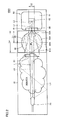
 図1は、本実施の形態に係るガス濃度測定装置の概略断面図である。図1を参照して、本実施の形態に係るガス濃度測定装置について説明する。
(Embodiment 1)
FIG. 1 is a schematic cross-sectional view of a gas concentration measuring apparatus according to the present embodiment. With reference to FIG. 1, the gas concentration measuring apparatus according to the present embodiment will be described.
 図1に示すように、本実施の形態に係るガス濃度測定装置100は、試料セル10、光源20、バンドパスフィルタ41、検出器60、および導波路形成部材90を備える。ガス濃度測定装置100は、赤外線を出射する光源20と赤外線を受光する受光部62を有する検出器60との間に流通される試料ガスの吸光度に応じてガス濃度を測定するものである。 As shown in FIG. 1, a gas concentration measuring apparatus 100 according to the present embodiment includes a sample cell 10, a light source 20, a bandpass filter 41, a detector 60, and a waveguide forming member 90. The gas concentration measuring apparatus 100 measures the gas concentration according to the absorbance of the sample gas flowing between the light source 20 that emits infrared light and the detector 60 having the light receiving unit 62 that receives infrared light.
 試料セル10は、内部に試料ガス流通空間を有し、試料ガスが流通可能に設けられている。たとえば、試料セル10の一端側(光源20側)には、試料ガス導入孔(不図示)が接続され、試料セル10の他端側(検出器60側)には、試料ガス導出孔(不図示)が接続されている。試料ガス導入孔を介して試料セル10に導出された試料ガスは、試料ガス導出孔から排出される。 The sample cell 10 has a sample gas circulation space inside and is provided so that the sample gas can be circulated. For example, a sample gas introduction hole (not shown) is connected to one end side (light source 20 side) of the sample cell 10, and a sample gas outlet hole (not shown) is connected to the other end side (detector 60 side) of the sample cell 10. Are connected. The sample gas led out to the sample cell 10 through the sample gas introduction hole is discharged from the sample gas lead-out hole.
 試料セル10は、光源20、導波路形成部材90、バンドパスフィルタ41および検出器60を内部に収容する。光源20、導波路形成部材90、バンドパスフィルタ41および検出器60は、たとえば、試料セル10の一端側(図中左側)からこの順で配置される。 The sample cell 10 accommodates the light source 20, the waveguide forming member 90, the band pass filter 41, and the detector 60 therein. The light source 20, the waveguide forming member 90, the band pass filter 41, and the detector 60 are arranged in this order from one end side (left side in the figure) of the sample cell 10, for example.
 光源20は、赤外線を出射する。光源20としては、たとえば所望の赤外線を含む広帯域な赤外線を放出するフィラメントランプやLEDランプ等を採用することができる。光源20から出射された赤外線の一部は、試料ガスの有する赤外吸収波長特性に基づいて吸収される。試料ガスは、例えば二酸化炭素であり、その吸収帯域は約4.3μmである。 The light source 20 emits infrared rays. As the light source 20, for example, a filament lamp or an LED lamp that emits broadband infrared light including desired infrared light can be employed. Part of the infrared light emitted from the light source 20 is absorbed based on the infrared absorption wavelength characteristics of the sample gas. The sample gas is, for example, carbon dioxide, and its absorption band is about 4.3 μm.
 導波路形成部材90は、筒状の内周面形状を有する導波部93、導波部93の一方側に形成され光源20からの赤外線を導入する入口部91、および、導波部93の他方側に形成され導波部93を通過した赤外線を検出器60側に向けて導出する出口部92を含む。導波路形成部材90は、試料ガスによって一部が吸収された赤外線を検出器60に向けて導出する。 The waveguide forming member 90 includes a waveguide portion 93 having a cylindrical inner peripheral surface shape, an inlet portion 91 that is formed on one side of the waveguide portion 93 and introduces infrared rays from the light source 20, and the waveguide portion 93. It includes an exit portion 92 that is formed on the other side and guides infrared rays that have passed through the waveguide portion 93 toward the detector 60 side. The waveguide forming member 90 guides infrared rays partially absorbed by the sample gas toward the detector 60.
 導波部93の内周面は、入口部91から出口部92に向かうにつれて断面積が小さくなる先細領域が設けられている。当該先細領域は、入口部91から出口部92に向かうにつれて周長が短くなる錐台形状を含んでいる。ここで錐台形状とは、円錐台形状および多角錐台形状を意味する。 The inner peripheral surface of the waveguide portion 93 is provided with a tapered region whose cross-sectional area decreases from the inlet portion 91 toward the outlet portion 92. The tapered region includes a frustum shape whose peripheral length becomes shorter from the inlet portion 91 toward the outlet portion 92. Here, the frustum shape means a frustum shape and a polygonal frustum shape.
 導波路形成部材90としては、ABS樹脂(アクリロニトリルブタジエンスチレン共重合合成樹脂)やPC樹脂(ポリカーボネート樹脂)等の樹脂材料を採用することができる。特に、導波路形成部材90としては、赤外領域の反射率が20%以下となる樹脂材料を採用することが好ましい。 As the waveguide forming member 90, a resin material such as ABS resin (acrylonitrile butadiene styrene copolymer synthetic resin) or PC resin (polycarbonate resin) can be employed. In particular, as the waveguide forming member 90, it is preferable to employ a resin material having a reflectance in the infrared region of 20% or less.
 バンドパスフィルタ41は、導波路形成部材90側に位置する検出器60の一端側に設けられている。バンドパスフィルタ41は、導波路形成部材90に向かい合う検出器60の表面に設けられた凹部64に嵌めこまれた状態で固定されている。 The band pass filter 41 is provided on one end side of the detector 60 located on the waveguide forming member 90 side. The bandpass filter 41 is fixed in a state of being fitted in a recess 64 provided on the surface of the detector 60 facing the waveguide forming member 90.
 バンドパスフィルタ41は、検出対象となる試料ガスの吸収帯の赤外線を透過するように構成されている。これにより、所望の波長帯を有する赤外線のみが検出器60に到達する。 The band-pass filter 41 is configured to transmit infrared rays in the absorption band of the sample gas to be detected. Thereby, only infrared rays having a desired wavelength band reach the detector 60.
 検出器60としては、サーモパイルやボロメータ等の赤外線検出器を採用することができる。検出器60は、本体部61、受光部62、凹部64を含む。本体部61の内部には、受光部62が埋設されている。受光部62は、バンドパスフィルタ41を介して導波路形成部材90の出口部92から導出された赤外線を受光する。 As the detector 60, an infrared detector such as a thermopile or a bolometer can be employed. The detector 60 includes a main body portion 61, a light receiving portion 62, and a concave portion 64. A light receiving unit 62 is embedded in the main body 61. The light receiving unit 62 receives infrared rays derived from the exit portion 92 of the waveguide forming member 90 via the bandpass filter 41.
 検出器60は、不図示の信号処理回路基板に電気的に接続される。受光部62によって受光した赤外線に基づき、検出器60は出力信号を信号処理回路基板に出力する。信号処理回路基板は、出力信号に基づき試料ガスの濃度を算出する。 The detector 60 is electrically connected to a signal processing circuit board (not shown). Based on the infrared light received by the light receiving unit 62, the detector 60 outputs an output signal to the signal processing circuit board. The signal processing circuit board calculates the concentration of the sample gas based on the output signal.
 続いて、バンドパスフィルタ41に入射される赤外線について説明する。一般的に、バンドパスフィルタ41の透過帯域は、入射角が増大するにつれて短波長側にシフトする。このように透過帯域が変化することにより、測定精度が低下するため、測定の際においては、バンドパスフィルタ41に入射する赤外線の入射角は小さいことが好ましい。 Subsequently, infrared rays incident on the bandpass filter 41 will be described. Generally, the transmission band of the bandpass filter 41 shifts to the short wavelength side as the incident angle increases. As the transmission band is changed in this way, the measurement accuracy is lowered. Therefore, it is preferable that the incident angle of the infrared ray incident on the bandpass filter 41 is small in the measurement.
 本実施の形態において導波路形成部材90は、透過位置に位置するバンドパスフィルタ41に入射される入射角の大きな赤外線が与える測定精度への影響を抑制するためのものである。 In the present embodiment, the waveguide forming member 90 is for suppressing the influence on the measurement accuracy given by infrared rays having a large incident angle incident on the bandpass filter 41 located at the transmission position.
 主として赤外線L1の最外線によって囲まれた領域と、赤外線L2の最外線によって囲まれた領域とによる論理和となる範囲内を直進的に進行する赤外線(たとえば図1中矢印L)がバンドパスフィルタ41を通過して受光部62に到達する。赤外線L1は、導波部93の周面に沿って検出器60側に直進する錐台形状を有する光である。赤外線L2は、たとえば導波路形成部材90の入口部91の図中下端から受光部62の図中上端に向けて直進する光を、入口部91の開口形状に沿って1回転させた際に形成される2つの円錐台形状を含む光である。 An infrared ray (for example, arrow L in FIG. 1) that travels straight in a range that is a logical sum of a region surrounded by the outermost line of infrared L1 and a region surrounded by the outermost line of infrared L2 is a bandpass filter. It passes through 41 and reaches the light receiving unit 62. The infrared ray L1 is light having a frustum shape that goes straight to the detector 60 side along the peripheral surface of the waveguide section 93. The infrared ray L2 is formed, for example, when light that travels straight from the lower end of the entrance portion 91 of the waveguide forming member 90 toward the upper end of the light receiving portion 62 is rotated once along the opening shape of the entrance portion 91. It is light including two truncated cone shapes.
 このような赤外線L1の最外線によって囲まれた領域と、赤外線L2の最外線によって囲まれた領域とによる論理和となる範囲内を直進的に進行する赤外線は、バンドパスフィルタ41を比較的小さな角度を持って透過する。 Infrared rays that travel straight in a range that is a logical sum of the region surrounded by the outermost line of the infrared ray L1 and the region surrounded by the outermost line of the infrared ray L2 cause the bandpass filter 41 to be relatively small. Transparent with an angle.
 一方、赤外線L4,L5は、導波部93の軸線方向に対して比較的大きな角度を持って入口部91から導波部93内に侵入する。赤外線L4,L5は、導波部93の内周面に複数回反射されながら、検出器60側に向けて進行する。 On the other hand, the infrared rays L4 and L5 enter the waveguide portion 93 from the entrance portion 91 at a relatively large angle with respect to the axial direction of the waveguide portion 93. Infrared rays L4 and L5 travel toward the detector 60 while being reflected by the inner peripheral surface of the waveguide section 93 a plurality of times.
 仮に、導波部93内の反射率が仮に100%とした場合には、赤外線L4,L5は、大きな入射角を持ってバンドパスフィルタ41に入射される場合がある。 If the reflectance in the waveguide section 93 is assumed to be 100%, the infrared rays L4 and L5 may be incident on the bandpass filter 41 with a large incident angle.
 ここで、本実施の形態においては、導波路形成部材90は、反射率が20%以下となる樹脂部材によって構成されているので、赤外線L4,L5は、導波部93内で繰り返し反射されることにより、吸収減衰される。たとえば、反射率10%の部材が用いられる場合には、赤外線が5回反射されることにより、反射率0.001%の部材によって1回反射された場合と同様の減衰効果を有する。導波路形成部材90の入口部91の開口面積S1を、出口部92の開口面積S2よりも大きくし、導波部93内に先細領域を設けることにより、赤外線L4,L5の反射回数を増加させることができる。 Here, in the present embodiment, since the waveguide forming member 90 is formed of a resin member having a reflectance of 20% or less, the infrared rays L4 and L5 are repeatedly reflected in the waveguide portion 93. Thus, absorption is attenuated. For example, when a member having a reflectivity of 10% is used, the infrared ray is reflected five times, thereby having the same attenuation effect as that when the member is reflected once by a member having a reflectivity of 0.001%. By making the opening area S1 of the inlet 91 of the waveguide forming member 90 larger than the opening area S2 of the outlet 92 and providing a tapered region in the waveguide 93, the number of reflections of the infrared rays L4 and L5 is increased. be able to.
 このように、導波路形成部材90は、入口部91から導波部93に進入した赤外線を先細領域にて多重反射させることにより、バンドパスフィルタ41に対して斜め方向に入射する赤外線のエネルギーを減衰させる。これにより、ガス濃度測定装置の測定精度を向上させることができる。 In this way, the waveguide forming member 90 multiplies the infrared rays that have entered the waveguide portion 93 from the entrance portion 91 into the tapered region, thereby converting the energy of the infrared rays incident on the bandpass filter 41 in an oblique direction. Attenuate. Thereby, the measurement accuracy of the gas concentration measuring apparatus can be improved.
 以上のように、本実施の形態に係るガス濃度測定装置100にあっては、導波路形成部材90を設けることにより、斜め方向に入射する赤外線のエネルギーを減衰させることができるため、ガス濃度測定装置100の測定精度を向上させることができる。 As described above, in the gas concentration measuring apparatus 100 according to the present embodiment, the provision of the waveguide forming member 90 can attenuate infrared energy incident in an oblique direction. The measurement accuracy of the apparatus 100 can be improved.
 なお、本実施の形態では、試料ガスは二酸化炭素としているが、これに限るものではない。例えば、一酸化炭素やCHやNOx等のガスであってもよい。 In this embodiment, the sample gas is carbon dioxide, but is not limited thereto. For example, a gas such as carbon monoxide, CH 4 or NOx may be used.
 (実施の形態2)
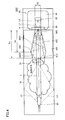
 図2は、本実施の形態に係るガス濃度測定装置の概略断面図である。図2を参照して、本実施の形態に係るガス濃度測定装置100Aについて説明する。
(Embodiment 2)
FIG. 2 is a schematic cross-sectional view of the gas concentration measuring apparatus according to the present embodiment. With reference to FIG. 2, a gas concentration measuring apparatus 100A according to the present embodiment will be described.
 図2に示すように、本実施の形態に係るガス濃度測定装置100Aは、実施の形態1に係るガス濃度測定装置100と比較した場合に、導波路形成部材90Aの導波部93Aの形状が相違する。その他の構成については、ほぼ同様である。 As shown in FIG. 2, the gas concentration measuring device 100A according to the present embodiment has a waveguide portion 93A having a shape of the waveguide forming member 90A when compared with the gas concentration measuring device 100 according to the first embodiment. Is different. Other configurations are almost the same.
 導波路形成部材90Aにおいても、入口部91Aの開口面積S1は、出口部92Aの開口面積S2よりも大きくなっている。導波部93Aの内部形状は、球体形状の一部を含む。導波部93Aの内周面のうち球面の一部を構成する部分は、入口部91Aと出口部92Aとの間に設けられている。 Also in the waveguide forming member 90A, the opening area S1 of the inlet portion 91A is larger than the opening area S2 of the outlet portion 92A. The internal shape of the waveguide section 93A includes a part of a spherical shape. A portion of the inner peripheral surface of the waveguide portion 93A that constitutes a part of the spherical surface is provided between the inlet portion 91A and the outlet portion 92A.
 当該球面の一部を構成する部分は、球体の中心部Mを境界にして、出口部92A側に向かう第1球面部95と、入口部91A側に向かう第2球面部96とを有する。第1球面部95から出口部92Aに至るまでの部分は、入口部91A側から出口部92A側に向かうにつれて断面積が小さくなる先細領域に相当するとともに、入口部91A側から出口部92A側に向かうにつれて周長が短くなる第1湾曲形状部に相当する。第2球面部96は、出口部92A側から入口部91A側に向かうにつれて周長が短くなる第2湾曲形状部に相当する。 The portion constituting a part of the spherical surface has a first spherical surface portion 95 directed toward the outlet portion 92A and a second spherical surface portion 96 directed toward the inlet portion 91A with the central portion M of the sphere as a boundary. The portion from the first spherical surface portion 95 to the outlet portion 92A corresponds to a tapered region whose sectional area decreases from the inlet portion 91A side to the outlet portion 92A side, and from the inlet portion 91A side to the outlet portion 92A side. It corresponds to the first curved shape portion whose circumference becomes shorter as it goes. The second spherical surface portion 96 corresponds to a second curved shape portion whose circumferential length becomes shorter from the outlet portion 92A side toward the inlet portion 91A side.
 導波部93Aが上記のような形状を有する場合であっても、主として赤外線L1の最外線によって囲まれた領域と、赤外線L2の最外線によって囲まれた領域とによる論理和となる範囲内を直進的に進行する赤外線(たとえば、図2中矢印L) が受光部62に到達する。赤外線L1は、入口部91Aと出口部92Aの周面に沿って検出器60側に直進する錐台形状を有する光である。赤外線L2は、実施の形態1と同様の光である。 Even in the case where the waveguide 93A has the shape as described above, the range of the logical sum of the region surrounded mainly by the outermost line of the infrared ray L1 and the region surrounded by the outermost line of the infrared ray L2 is within the range. Infrared rays traveling in a straight line (for example, arrow L in FIG. 2) reach the light receiving unit 62. The infrared ray L1 is light having a frustum shape that goes straight to the detector 60 side along the peripheral surfaces of the inlet portion 91A and the outlet portion 92A. Infrared ray L2 is the same light as in the first embodiment.
 導波部93Aの軸線方向に対して比較的大きな角度を持って入口部91Aから導波部93A内に侵入した赤外線L4,L5は、第1球面部95および第2球面部96にて複数回反射され、入口部91Aから出射される。 Infrared rays L4 and L5 that have entered the waveguide portion 93A from the entrance portion 91A at a relatively large angle with respect to the axial direction of the waveguide portion 93A are transmitted a plurality of times at the first spherical portion 95 and the second spherical portion 96. It is reflected and emitted from the entrance 91A.
 入口部91Aから出射された赤外線L4,L5は、バンドパスフィルタ41に入射されない。導波部93Aでの反射回数を増加させるために、導波部93Aの軸線方向における第1球面部95から出口部92Aに至るまでの部分の長さLbは、導波路形成部材90の長さLaの半分以上であることが好ましい。 The infrared rays L4 and L5 emitted from the entrance 91A are not incident on the bandpass filter 41. In order to increase the number of reflections at the waveguide portion 93A, the length Lb of the portion from the first spherical portion 95 to the exit portion 92A in the axial direction of the waveguide portion 93A is the length of the waveguide forming member 90. It is preferably at least half of La.
 このように、本実施の形態においては、バンドパスフィルタ41に対して斜め方向に入射する赤外線のエネルギーを減衰させることができるとともに、斜め方向に入射する赤外線の一部を入口部91Aから出射することができる。これにより、ガス濃度測定装置100Aの測定精度をさらに向上させることができる。 As described above, in the present embodiment, it is possible to attenuate the infrared energy incident in the oblique direction with respect to the bandpass filter 41, and to emit a part of the infrared light incident in the oblique direction from the inlet portion 91A. be able to. Thereby, the measurement accuracy of the gas concentration measuring apparatus 100A can be further improved.
 (実施の形態3)
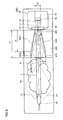
 図3は、本実施の形態に係るガス濃度測定装置の概略断面図である。図3を参照して、本実施の形態に係るガス濃度測定装置100Bについて説明する。
(Embodiment 3)
FIG. 3 is a schematic cross-sectional view of the gas concentration measuring apparatus according to the present embodiment. With reference to FIG. 3, the gas concentration measuring apparatus 100B according to the present embodiment will be described.
 図3に示すように、本実施の形態に係るガス濃度測定装置100Bは、実施の形態1に係るガス濃度測定装置100と比較した場合に、導波路形成部材90Bの導波部93Bの形状が相違する。その他の構成については、ほぼ同様である。 As shown in FIG. 3, the gas concentration measuring device 100B according to the present embodiment has a waveguide portion 93B of the waveguide forming member 90B having a shape that is different from that of the gas concentration measuring device 100 according to the first embodiment. Is different. Other configurations are almost the same.
 導波路形成部材90Bにおいても、入口部91Bの開口面積S1は、出口部92Bの開口面積S2よりも大きくなっている。導波部93Bの内部形状は、第1湾曲形状部93B1および第2湾曲形状部93B2を含む。導波部93Bは、最大周長部94Bを含む。最大周長部94Bは、入口部91Bと出口部92Bとの間に設けられている。 Also in the waveguide forming member 90B, the opening area S1 of the inlet portion 91B is larger than the opening area S2 of the outlet portion 92B. The internal shape of the waveguide portion 93B includes a first curved shape portion 93B1 and a second curved shape portion 93B2. The waveguide portion 93B includes a maximum circumferential length portion 94B. The maximum circumferential length portion 94B is provided between the inlet portion 91B and the outlet portion 92B.
 第1湾曲形状部93B1は、最大周長部94Bから出口部92Bに至るまでの導波部93Bの内部形状である。第1湾曲形状部93B1は、入口部91B側から出口部92Bに向かうにつれて周長が短くなるように設けられている。 The first curved shape portion 93B1 is an internal shape of the waveguide portion 93B from the maximum peripheral length portion 94B to the outlet portion 92B. The first curved shape portion 93B1 is provided so that the circumferential length becomes shorter from the inlet portion 91B side toward the outlet portion 92B.
 第2湾曲形状部93B2は、最大周長部94Bから入口部91Bに至るまでの導波部93Bの内部形状である。第2湾曲形状部93B2は、出口部92B側から入口部91Bに向かうにつれて周長が短くなるように設けられている。 The second curved shape portion 93B2 is an internal shape of the waveguide portion 93B from the maximum circumferential length portion 94B to the inlet portion 91B. The second curved shape portion 93B2 is provided so that the circumferential length becomes shorter from the outlet portion 92B side toward the inlet portion 91B.
 この場合においても、主として赤外線L1の最外線によって囲まれた領域と、赤外線L2の最外線によって囲まれた領域とによる論理和となる範囲内を直進的に進行する赤外線が受光部62に到達する。赤外線L1は、入口部91Bと出口部92Bの周縁に沿って検出器60側に直進する錐台形状を有する光である。赤外線L2は、実施の形態1と同様の光である。 Also in this case, the infrared ray that travels straight in the range that is the logical sum of the region surrounded by the outermost line of the infrared ray L1 and the region surrounded by the outermost line of the infrared ray L2 reaches the light receiving unit 62. . The infrared ray L1 is light having a frustum shape that goes straight to the detector 60 side along the periphery of the inlet portion 91B and the outlet portion 92B. Infrared ray L2 is the same light as in the first embodiment.
 導波路形成部材90Bの軸線方向における第1湾曲形状部93B1の長さLbは、当該軸線方向における導波路形成部材90Bの長さLaの半分以上であることが好ましい。このような長さ関係を有することにより、導波部93Bの軸線方向に対して比較的大きな角度を持って入口部91Bから侵入する赤外線L4,L5を第1湾曲形状部93B1および第2湾曲形状部93B2内で複数回反射させることができるとともに、入口部91Bから出射することができる。 The length Lb of the first curved portion 93B1 in the axial direction of the waveguide forming member 90B is preferably at least half the length La of the waveguide forming member 90B in the axial direction. By having such a length relationship, infrared rays L4 and L5 that enter from the entrance portion 91B with a relatively large angle with respect to the axial direction of the waveguide portion 93B are transmitted to the first curved shape portion 93B1 and the second curved shape. The light can be reflected a plurality of times within the portion 93B2 and can be emitted from the inlet portion 91B.
 これにより、本実施の形態においても、バンドパスフィルタ41に対して斜め方向に入射する赤外線のエネルギーを確実に減衰させることができる。この結果、ガス濃度測定装置100Bの測定精度を向上させることができる。 Thereby, also in the present embodiment, it is possible to surely attenuate the energy of infrared rays incident on the band pass filter 41 in an oblique direction. As a result, the measurement accuracy of the gas concentration measuring device 100B can be improved.
 (実施の形態4)
 図4は、本実施の形態に係るガス濃度測定装置の概略断面図である。図4を参照して、本実施の形態に係るガス濃度測定装置100Cについて説明する。
(Embodiment 4)
FIG. 4 is a schematic cross-sectional view of the gas concentration measuring apparatus according to the present embodiment. With reference to FIG. 4, a gas concentration measuring apparatus 100C according to the present embodiment will be described.
 図4に示すように、本実施の形態に係るガス濃度測定装置100Cは、実施の形態1に係るガス濃度測定装置100と比較した場合に、導波路形成部材90Cの導波部93Cの形状が相違する。その他の構成については、ほぼ同様である。 As shown in FIG. 4, the gas concentration measuring apparatus 100C according to the present embodiment has a waveguide portion 93C having a shape of the waveguide forming member 90C when compared with the gas concentration measuring apparatus 100 according to the first embodiment. Is different. Other configurations are almost the same.
 導波路形成部材90Cにおいても、入口部91Cの開口面積S1は、出口部92Cの開口面積S2よりも大きくなっている。導波部93Cの内部形状は、第1錐台形状部93C1および第2錐台形状部93C2を含む。導波部93Cは、最大周長部94Cを含む。最大周長部94Cは、入口部91Cと出口部92Cとの間に設けられている。 Also in the waveguide forming member 90C, the opening area S1 of the inlet portion 91C is larger than the opening area S2 of the outlet portion 92C. The internal shape of the waveguide 93C includes a first frustum-shaped portion 93C1 and a second frustum-shaped portion 93C2. The waveguide portion 93C includes a maximum circumferential length portion 94C. The maximum circumferential length portion 94C is provided between the inlet portion 91C and the outlet portion 92C.
 第1錐台形状部93C1は、最大周長部94Cから出口部92Cに至るまでの導波部93Cの内部形状である。第1錐台形状部93C1は、入口部91C側から出口部92Cに向かうにつれて周長が短くなるように設けられている。 The first frustum-shaped portion 93C1 is the internal shape of the waveguide portion 93C from the maximum circumferential length portion 94C to the outlet portion 92C. The first frustum-shaped portion 93C1 is provided so that the circumferential length decreases from the inlet portion 91C side toward the outlet portion 92C.
 第2錐台形状部93C2は、最大周長部94Cから入口部91Cに至るまでの導波部93Cの内部形状である。第2錐台形状部93C2は、出口部92C側から入口部91Cに向かうにつれて周長が短くなるように設けられている。 The second frustum-shaped portion 93C2 is the internal shape of the waveguide portion 93C from the maximum circumferential length portion 94C to the inlet portion 91C. The second frustum-shaped portion 93C2 is provided such that the circumferential length decreases from the outlet portion 92C side toward the inlet portion 91C.
 この場合においても、主として赤外線L1の最外線によって囲まれた領域と、赤外線L2の最外線によって囲まれた領域とによる論理和となる範囲内を直進的に進行する赤外線が受光部62に到達する。赤外線L1は、入口部91Cと出口部92Cの周縁に沿って検出器60側に直進する錐台形状を有する光である。赤外線L2は、実施の形態1と同様の光である。 Also in this case, the infrared ray that travels straight in the range that is the logical sum of the region surrounded by the outermost line of the infrared ray L1 and the region surrounded by the outermost line of the infrared ray L2 reaches the light receiving unit 62. . The infrared ray L1 is light having a frustum shape that goes straight to the detector 60 side along the periphery of the inlet portion 91C and the outlet portion 92C. Infrared ray L2 is the same light as in the first embodiment.
 導波路形成部材90Cの軸線方向における第1錐台形状部93C1の長さLbは、当該軸線方向における導波路形成部材90Cの長さLaの半分以上であることが好ましい。このような長さ関係を有することにより、導波部93Cの軸線方向に対して比較的大きな角度を持って入口部91Cから侵入する赤外線L4等を第1錐台形状部93C1および第2錐台形状部93C2内で複数回反射させることができる。 The length Lb of the first frustum-shaped portion 93C1 in the axial direction of the waveguide forming member 90C is preferably not less than half the length La of the waveguide forming member 90C in the axial direction. By having such a length relationship, infrared rays L4 and the like entering from the entrance portion 91C with a relatively large angle with respect to the axial direction of the waveguide portion 93C are transmitted to the first frustum-shaped portion 93C1 and the second frustum. It can be reflected a plurality of times within the shape portion 93C2.
 これにより、本実施の形態に係るガス濃度測定装置100Cにあっても、バンドパスフィルタ41に対して斜め方向に入射する赤外線のエネルギーを確実に減衰させることができる。この結果、ガス濃度測定装置の測定精度を向上させることができる。 Thereby, even in the gas concentration measuring apparatus 100C according to the present embodiment, it is possible to reliably attenuate the energy of infrared rays incident on the band-pass filter 41 in an oblique direction. As a result, the measurement accuracy of the gas concentration measuring device can be improved.
 (実施の形態5)
 図5は、本実施の形態に係るガス濃度測定装置の概略断面図である。図5を参照して、本実施の形態に係るガス濃度測定装置100Dについて説明する。
(Embodiment 5)
FIG. 5 is a schematic cross-sectional view of the gas concentration measuring apparatus according to the present embodiment. With reference to FIG. 5, a gas concentration measurement apparatus 100D according to the present embodiment will be described.
 図5に示すように、本実施の形態に係るガス濃度測定装置100Dは、実施の形態4に係るガス濃度測定装置100Cと比較した場合に、導波路形成部材90Dの導波部93Dの形状が相違する。 As shown in FIG. 5, the gas concentration measuring apparatus 100D according to the present embodiment has a waveguide portion 93D of the waveguide forming member 90D having a shape that is different from that of the gas concentration measuring apparatus 100C according to the fourth embodiment. Is different.
 導波路形成部材90Dも入口部91Dの開口面積S1は、出口部92Dの開口面積S2よりも大きくなっている。導波部93Dの内部形状は、錐台形状部93D1および柱体形状部93D2を含む。錐台形状部93D1は、実施の形態4に係る第1錐台形状部93C1とほぼ同様の形状を有する。また、錐台形状部93D1と導波路形成部材90Dとの長さ関係も、実施の形態4に係る第1錐台形状部93C1と導波路形成部材90Cとの関係と同様である。 In the waveguide forming member 90D, the opening area S1 of the inlet portion 91D is larger than the opening area S2 of the outlet portion 92D. The internal shape of the waveguide portion 93D includes a frustum-shaped portion 93D1 and a columnar shape portion 93D2. The frustum-shaped portion 93D1 has substantially the same shape as the first frustum-shaped portion 93C1 according to the fourth embodiment. The length relationship between the frustum-shaped portion 93D1 and the waveguide forming member 90D is the same as the relationship between the first frustum-shaped portion 93C1 and the waveguide forming member 90C according to the fourth embodiment.
 柱体形状部93D2は、入口部91Dから上流側に位置する錐台形状部93D1の端部にかけて周長が一定となるように設けられている。柱体形状部93D2の周長は、最大となるように設けられている。 The columnar shape portion 93D2 is provided so that the circumferential length is constant from the inlet portion 91D to the end of the frustum-shaped portion 93D1 located on the upstream side. The circumferential length of the columnar portion 93D2 is provided to be the maximum.
 このように設けられた場合であっても、導波部93Dの軸線方向に対して比較的大きな角度を持って入口部91Dから侵入する赤外線L4,L5を錐台形状部93D1および柱体形状部93D2内で複数回反射させることができる。 Even in such a case, the infrared rays L4 and L5 entering from the entrance portion 91D with a relatively large angle with respect to the axial direction of the waveguide portion 93D are transmitted through the frustum-shaped portion 93D1 and the columnar shape portion. It can be reflected multiple times within 93D2.
 これにより、本実施の形態に係るガス濃度測定装置100Dにあっても、バンドパスフィルタ41に対して斜め方向に入射する赤外線のエネルギーを確実に減衰させることができる。この結果、ガス濃度測定装置の測定精度を向上させることができる。 Thereby, even in the gas concentration measurement apparatus 100D according to the present embodiment, the energy of infrared rays incident on the bandpass filter 41 in an oblique direction can be surely attenuated. As a result, the measurement accuracy of the gas concentration measuring device can be improved.
 なお、本実施の形態においては、柱体形状部が入口部91D側に設けられ、錐台形状部が出口部92D側に設けられる場合を例示して説明したが、これに限定されず、柱体形状部が出口部92D側に設けられ、錐台形状部が入口部91D側に設けられてもよい。この場合には、柱体形状部の周長は、最少となるように設けられる。 In the present embodiment, the case where the columnar shape portion is provided on the inlet portion 91D side and the frustum-shaped portion is provided on the outlet portion 92D side has been described as an example. The body-shaped part may be provided on the outlet part 92D side, and the frustum-shaped part may be provided on the inlet part 91D side. In this case, the peripheral length of the columnar shape portion is provided to be minimized.
 上述した実施の形態2においては、入口部91Aと上流側における第2球面部96の端部とを接続する部分(第1接続部)、および、下流側における第1球面部95の端部と出口部92Aとを接続する部分(第2接続部)とが、入口部91A側から出口部92A側に向かうにつれて周長が短くなるように設けられる場合を例示して説明したが、これに限定されず、第1接続部および第2接続部の少なくともいずれかが、周長が一定となる柱体形状に設けられていてもよい。 In the second embodiment described above, the portion connecting the inlet 91A and the end of the second spherical portion 96 on the upstream side (first connecting portion), and the end of the first spherical portion 95 on the downstream side Although the case where the portion (second connecting portion) that connects the outlet portion 92A is provided so as to have a shorter circumference as it goes from the inlet portion 91A side to the outlet portion 92A side has been described, it is limited to this. Instead, at least one of the first connection portion and the second connection portion may be provided in a columnar shape having a constant circumference.
 上述した実施の形態3においては、入口部91Bから最大周長部94Bにかけて、第2湾曲形状部93B2が設けられる場合を例示して説明したが、これに限定されず、第2湾曲形状部93B2に代えて、入口部91Bから最大周長部94Bにかけて周長が一定となるように、柱体形状部が設けられていてもよい。 In Embodiment 3 described above, the case where the second curved shape portion 93B2 is provided from the inlet portion 91B to the maximum circumferential length portion 94B has been described as an example. However, the present invention is not limited to this, and instead of the second curved shape portion 93B2. In addition, the columnar shape portion may be provided so that the peripheral length is constant from the inlet portion 91B to the maximum peripheral length portion 94B.
 以上、本発明の実施の形態について説明したが、今回開示された実施の形態はすべての点で例示であって制限的なものではない。本発明の範囲は請求の範囲によって示され、請求の範囲と均等の意味および範囲内でのすべての変更が含まれる。 As mentioned above, although embodiment of this invention was described, embodiment disclosed this time is an illustration and restrictive at no points. The scope of the present invention is defined by the terms of the claims, and includes meanings equivalent to the terms of the claims and all changes within the scope.
 10 試料セル、20 光源、41 バンドパスフィルタ、60 検出器、61 本体部、62 受光部、64 凹部、90,90A,90B,90C,90D 導波路形成部材、91,91A,91B,91C,91D 入口部、92,92A,92B,92C,92D 出口部、93,93A,93B,93C,93D 導波部、93B1 第1湾曲形状部、93B2 第2湾曲形状部、93C1 第1錐台形状部、93C2 第2錐台形状部、93D1 錐台形状部、93D2 柱体形状部、94B,94C 最大周長部、95 第1球面部、96 第2球面部、100,100A,100B,100C,100D ガス濃度測定装置。 10 sample cells, 20 light sources, 41 bandpass filters, 60 detectors, 61 main body parts, 62 light receiving parts, 64 concave parts, 90, 90A, 90B, 90C, 90D waveguide forming members, 91, 91A, 91B, 91C, 91D Inlet part, 92, 92A, 92B, 92C, 92D outlet part, 93, 93A, 93B, 93C, 93D waveguide part, 93B1, first curved shape part, 93B2, second curved shape part, 93C1, first frustum shaped part, 93C2 second frustum shape part, 93D1 frustum shape part, 93D2 columnar shape part, 94B, 94C maximum circumference part, 95 first spherical part, 96 second spherical part, 100, 100A, 100B, 100C, 100D gas concentration measurement apparatus.

Claims (7)

  1.  赤外線を出射する光源と、
     前記光源からの前記赤外線をバンドパスフィルタを介して検出する検出器と、
     筒状の内周面形状を有する導波部、前記導波部の一方側に形成され前記光源からの前記赤外線を導入する入口部、および、前記導波部の他方側に形成され前記導波部を通過した前記赤外線を前記検出器側に向けて導出する出口部を含む導波路形成部材と、を備え、
     前記導波部の内周面の一部または全部には、前記入口部から前記出口部に向かうにつれて断面積が小さくなる先細領域が設けられており、
     前記導波路形成部材は、前記入口部から前記導波部に進入した前記赤外線を前記先細領域に反射させることにより、前記バンドパスフィルタに対して斜め方向に入射する前記赤外線のエネルギーを減衰させる、ガス濃度測定装置。
    A light source that emits infrared light;
    A detector for detecting the infrared ray from the light source through a band-pass filter;
    A waveguide portion having a cylindrical inner peripheral surface shape, an entrance portion for introducing the infrared rays from the light source formed on one side of the waveguide portion, and the waveguide formed on the other side of the waveguide portion A waveguide forming member including an exit portion that guides the infrared light that has passed through the portion toward the detector, and
    In a part or all of the inner peripheral surface of the waveguide portion, a tapered region having a cross-sectional area that decreases from the entrance portion toward the exit portion is provided,
    The waveguide forming member attenuates the energy of the infrared rays incident on the bandpass filter in an oblique direction by reflecting the infrared rays that have entered the waveguide portion from the entrance portion to the tapered region. Gas concentration measuring device.
  2.  前記導波部の前記内周面に設けられた前記先細領域は、前記入口部から前記出口部に向かうにつれて周長が短くなる錐台形状部を含んでいる、請求項1に記載のガス濃度測定装置。 2. The gas concentration according to claim 1, wherein the tapered region provided on the inner peripheral surface of the waveguide portion includes a frustum-shaped portion whose peripheral length decreases from the inlet portion toward the outlet portion. measuring device.
  3.  前記入口部の開口面積は、前記出口部の開口面積よりも大きい、請求項1または2に記載のガス濃度測定装置。 The gas concentration measuring device according to claim 1 or 2, wherein an opening area of the inlet portion is larger than an opening area of the outlet portion.
  4.  前記導波部の前記内周面に設けられた前記先細領域は、前記入口部から前記出口部に向かうにつれて周長が短くなる第1湾曲形状部を含んでいる、請求項1から3のいずれか1項に記載のガス濃度測定装置。 4. The taper region provided on the inner peripheral surface of the waveguide portion includes a first curved shape portion having a circumferential length that decreases from the inlet portion toward the outlet portion. 5. The gas concentration measuring device according to claim 1.
  5.  前記導波部の軸線方向において、前記第1湾曲形状部の長さは、前記導波部の長さの半分以上である、請求項4に記載のガス濃度測定装置。 The gas concentration measuring device according to claim 4, wherein a length of the first curved portion is not less than half of a length of the waveguide portion in an axial direction of the waveguide portion.
  6.  前記導波部の前記内周面には、前記出口部から前記入口部に向かうにつれて周長が短くなる第2湾曲形状部が設けられている、請求項1から5のいずれか1項に記載のガス濃度測定装置。 6. The second curved shape portion according to claim 1, wherein a second curved shape portion having a circumferential length that decreases from the outlet portion toward the inlet portion is provided on the inner peripheral surface of the waveguide portion. Gas concentration measuring device.
  7.  前記導波路形成部材が、樹脂材料からなる、請求項1から6のいずれか1項に記載のガス濃度測定装置。 The gas concentration measuring device according to any one of claims 1 to 6, wherein the waveguide forming member is made of a resin material.
PCT/JP2015/066873 2014-07-03 2015-06-11 Gas concentration measurement device WO2016002467A1 (en)

Priority Applications (3)

Application Number Priority Date Filing Date Title
JP2016531226A JP6245366B2 (en) 2014-07-03 2015-06-11 Gas concentration measuring device
EP15815028.4A EP3165905B1 (en) 2014-07-03 2015-06-11 Gas concentration measurement device
US15/384,362 US10254222B2 (en) 2014-07-03 2016-12-20 Gas concentration measurement device

Applications Claiming Priority (2)

Application Number Priority Date Filing Date Title
JP2014137787 2014-07-03
JP2014-137787 2014-07-03

Related Child Applications (1)

Application Number Title Priority Date Filing Date
US15/384,362 Continuation US10254222B2 (en) 2014-07-03 2016-12-20 Gas concentration measurement device

Publications (1)

Publication Number Publication Date
WO2016002467A1 true WO2016002467A1 (en) 2016-01-07

Family

ID=55019016

Family Applications (1)

Application Number Title Priority Date Filing Date
PCT/JP2015/066873 WO2016002467A1 (en) 2014-07-03 2015-06-11 Gas concentration measurement device

Country Status (4)

Country Link
US (1) US10254222B2 (en)
EP (1) EP3165905B1 (en)
JP (1) JP6245366B2 (en)
WO (1) WO2016002467A1 (en)

Cited By (1)

* Cited by examiner, † Cited by third party
Publication number Priority date Publication date Assignee Title
US10161859B2 (en) 2016-10-27 2018-12-25 Honeywell International Inc. Planar reflective ring

Families Citing this family (1)

* Cited by examiner, † Cited by third party
Publication number Priority date Publication date Assignee Title
EP3444591B1 (en) * 2016-04-15 2023-06-28 PHC Holdings Corporation Gas sensor and constant-temperature apparatus

Citations (3)

* Cited by examiner, † Cited by third party
Publication number Priority date Publication date Assignee Title
JP2004117259A (en) * 2002-09-27 2004-04-15 Horiba Ltd Vehicle mounted type hc measuring apparatus
JP2007501404A (en) * 2003-05-13 2007-01-25 ハイマン・センサー・ゲゼルシャフト・ミット・ベシュレンクテル・ハフツング Infrared sensor utilizing optimized surface
JP2012202918A (en) * 2011-03-28 2012-10-22 Horiba Stec Co Ltd Spectrophotometer and calibration method for the same

Family Cites Families (20)

* Cited by examiner, † Cited by third party
Publication number Priority date Publication date Assignee Title
US4011451A (en) * 1975-07-03 1977-03-08 Waters Associates, Incorporated Novel photometric system
IE44010B1 (en) * 1976-02-25 1981-07-29 Rossiter V Method and apparatus for examining the infrared spectrum of small quantities of materials in the vapour phase
US4084909A (en) * 1976-07-19 1978-04-18 International Business Machines Corporation Drum monochromator
US4736103A (en) * 1986-03-07 1988-04-05 Westinghouse Electric Corp. Spectrometer test gas chamber
JPH07236040A (en) * 1994-02-22 1995-09-05 Nippon Avionics Co Ltd Color line sensor camera
JPH10309281A (en) * 1997-05-13 1998-11-24 Olympus Optical Co Ltd Fluorescent diagnostic device
JP2004239611A (en) 1999-10-12 2004-08-26 Nok Corp Co sensor
SE520664C2 (en) * 2000-04-27 2003-08-05 Senseair Ab Carbon dioxide-adapted gas cell
JP3771849B2 (en) 2001-09-27 2006-04-26 株式会社堀場製作所 Infrared gas analysis method and apparatus
JP2003215037A (en) * 2002-01-25 2003-07-30 Horiba Ltd Method and apparatus for hc analysis by ndir method
US6865472B2 (en) 2002-09-27 2005-03-08 Horiba Ltd. Vehicle-installed exhaust gas analyzing apparatus
JP4663258B2 (en) * 2003-06-17 2011-04-06 オリンパス株式会社 Endoscope device
JP3991029B2 (en) * 2003-12-19 2007-10-17 株式会社日立ハイテクノロジーズ Nucleic acid analyzer
KR100791961B1 (en) * 2004-12-24 2008-01-04 코리아디지탈 주식회사 Optical Structure of Non-dispersive Infrared Gas Analyzer
JP2010223610A (en) * 2009-03-19 2010-10-07 Toyota Central R&D Labs Inc Self-forming optical waveguide sensor
EP2444791B1 (en) * 2010-10-25 2020-04-15 General Electric Company Gas analyzer for measuring at least two components of a gas
JP5870270B2 (en) * 2011-10-24 2016-02-24 パナソニックIpマネジメント株式会社 Detector
JP2013120153A (en) * 2011-12-08 2013-06-17 Panasonic Corp Gas component detector
AU2013308186B9 (en) * 2012-08-30 2017-09-21 Iti Scotland - Scottish Enterprise Long wavelength infrared detection and imaging with long wavelength infrared source
US9651475B2 (en) 2012-11-30 2017-05-16 Panasonic Intellectual Property Management Co., Ltd. Optical sensor apparatus and method of producing optical element used in optical sensor apparatus

Patent Citations (3)

* Cited by examiner, † Cited by third party
Publication number Priority date Publication date Assignee Title
JP2004117259A (en) * 2002-09-27 2004-04-15 Horiba Ltd Vehicle mounted type hc measuring apparatus
JP2007501404A (en) * 2003-05-13 2007-01-25 ハイマン・センサー・ゲゼルシャフト・ミット・ベシュレンクテル・ハフツング Infrared sensor utilizing optimized surface
JP2012202918A (en) * 2011-03-28 2012-10-22 Horiba Stec Co Ltd Spectrophotometer and calibration method for the same

Cited By (1)

* Cited by examiner, † Cited by third party
Publication number Priority date Publication date Assignee Title
US10161859B2 (en) 2016-10-27 2018-12-25 Honeywell International Inc. Planar reflective ring

Also Published As

Publication number Publication date
EP3165905A4 (en) 2018-02-21
US20170102328A1 (en) 2017-04-13
US10254222B2 (en) 2019-04-09
JPWO2016002467A1 (en) 2017-04-27
EP3165905B1 (en) 2019-10-02
JP6245366B2 (en) 2017-12-13
EP3165905A1 (en) 2017-05-10

Similar Documents

Publication Publication Date Title
JP5334846B2 (en) Spectroscopic detector and method for determining blood and biomarker substances in liquid
TWI513974B (en) Detector
CN110383043B (en) Optical gas sensor
US20210341335A1 (en) Infrared spectrophotometer
US9323035B2 (en) Annular optical device
US5610400A (en) Spectroscopic measuring sensor for the analysis of mediums
JP6245366B2 (en) Gas concentration measuring device
KR20180103760A (en) Optical sensor with deposition sensor
US9915604B2 (en) Gas concentration measurement device
JP7291109B2 (en) Paper web measuring device and method
CN206594055U (en) Moisture content determining device
JPS59173734A (en) Infrared-ray gas analysis meter
KR102381817B1 (en) Light waveguide including multiple elliptical reflectors
CN109682772B (en) Non-spectroscopic infrared gas sensor
CN115015150A (en) Multi-channel redundant high-precision combustible gas concentration sensor
KR20160105062A (en) Gas sense module
CN108732120A (en) The device and method of signal enhancing for infrared detector
JP2010276427A (en) Gas sensor
JPS6011145A (en) Measuring device of foreign matter
JPH02245637A (en) Sludge densitometer

Legal Events

Date Code Title Description
121 Ep: the epo has been informed by wipo that ep was designated in this application

Ref document number: 15815028

Country of ref document: EP

Kind code of ref document: A1

REEP Request for entry into the european phase

Ref document number: 2015815028

Country of ref document: EP

WWE Wipo information: entry into national phase

Ref document number: 2015815028

Country of ref document: EP

ENP Entry into the national phase

Ref document number: 2016531226

Country of ref document: JP

Kind code of ref document: A

NENP Non-entry into the national phase

Ref country code: DE