WO2015198562A2 - Imaging device and method - Google Patents
Imaging device and method Download PDFInfo
- Publication number
- WO2015198562A2 WO2015198562A2 PCT/JP2015/003023 JP2015003023W WO2015198562A2 WO 2015198562 A2 WO2015198562 A2 WO 2015198562A2 JP 2015003023 W JP2015003023 W JP 2015003023W WO 2015198562 A2 WO2015198562 A2 WO 2015198562A2
- Authority
- WO
- WIPO (PCT)
- Prior art keywords
- array
- phase difference
- imaging
- light
- elements
- Prior art date
Links
- 238000003384 imaging method Methods 0.000 title claims abstract description 179
- 238000000034 method Methods 0.000 title claims abstract description 62
- 238000000701 chemical imaging Methods 0.000 claims abstract description 54
- 230000003287 optical effect Effects 0.000 claims abstract description 35
- 238000001514 detection method Methods 0.000 claims description 28
- 230000000704 physical effect Effects 0.000 claims description 3
- 230000008569 process Effects 0.000 description 30
- 230000003595 spectral effect Effects 0.000 description 27
- 239000008280 blood Substances 0.000 description 21
- 210000004369 blood Anatomy 0.000 description 21
- 238000012545 processing Methods 0.000 description 21
- 238000009534 blood test Methods 0.000 description 17
- 238000010586 diagram Methods 0.000 description 16
- 210000001367 artery Anatomy 0.000 description 14
- 239000000306 component Substances 0.000 description 13
- 238000005516 engineering process Methods 0.000 description 13
- 239000000463 material Substances 0.000 description 11
- 238000012986 modification Methods 0.000 description 11
- 230000004048 modification Effects 0.000 description 11
- 210000003462 vein Anatomy 0.000 description 11
- 238000001228 spectrum Methods 0.000 description 10
- 239000004065 semiconductor Substances 0.000 description 8
- 230000010287 polarization Effects 0.000 description 7
- 238000003860 storage Methods 0.000 description 7
- 102000001554 Hemoglobins Human genes 0.000 description 6
- 108010054147 Hemoglobins Proteins 0.000 description 6
- 239000011651 chromium Substances 0.000 description 6
- 230000004907 flux Effects 0.000 description 6
- 238000005259 measurement Methods 0.000 description 6
- 230000035945 sensitivity Effects 0.000 description 6
- WQZGKKKJIJFFOK-GASJEMHNSA-N Glucose Natural products OC[C@H]1OC(O)[C@H](O)[C@@H](O)[C@@H]1O WQZGKKKJIJFFOK-GASJEMHNSA-N 0.000 description 5
- 241000220225 Malus Species 0.000 description 5
- QVGXLLKOCUKJST-UHFFFAOYSA-N atomic oxygen Chemical compound [O] QVGXLLKOCUKJST-UHFFFAOYSA-N 0.000 description 5
- 239000006185 dispersion Substances 0.000 description 5
- 239000008103 glucose Substances 0.000 description 5
- 150000002632 lipids Chemical class 0.000 description 5
- 229910052760 oxygen Inorganic materials 0.000 description 5
- 239000001301 oxygen Substances 0.000 description 5
- 238000010521 absorption reaction Methods 0.000 description 4
- 238000004458 analytical method Methods 0.000 description 4
- 238000003491 array Methods 0.000 description 4
- 230000008859 change Effects 0.000 description 4
- 239000003086 colorant Substances 0.000 description 4
- 238000012937 correction Methods 0.000 description 4
- 239000011521 glass Substances 0.000 description 4
- 238000004519 manufacturing process Methods 0.000 description 4
- 239000000758 substrate Substances 0.000 description 4
- VYZAMTAEIAYCRO-UHFFFAOYSA-N Chromium Chemical compound [Cr] VYZAMTAEIAYCRO-UHFFFAOYSA-N 0.000 description 3
- 230000008901 benefit Effects 0.000 description 3
- 229910052804 chromium Inorganic materials 0.000 description 3
- 230000006854 communication Effects 0.000 description 3
- 230000009467 reduction Effects 0.000 description 3
- 238000005070 sampling Methods 0.000 description 3
- 239000013598 vector Substances 0.000 description 3
- 238000005033 Fourier transform infrared spectroscopy Methods 0.000 description 2
- 230000004075 alteration Effects 0.000 description 2
- 235000021016 apples Nutrition 0.000 description 2
- 230000005540 biological transmission Effects 0.000 description 2
- 238000006243 chemical reaction Methods 0.000 description 2
- 238000004891 communication Methods 0.000 description 2
- 230000000295 complement effect Effects 0.000 description 2
- 238000013461 design Methods 0.000 description 2
- 238000011161 development Methods 0.000 description 2
- 238000001312 dry etching Methods 0.000 description 2
- 235000013305 food Nutrition 0.000 description 2
- 230000006870 function Effects 0.000 description 2
- 229910044991 metal oxide Inorganic materials 0.000 description 2
- 150000004706 metal oxides Chemical class 0.000 description 2
- 238000003672 processing method Methods 0.000 description 2
- VYPSYNLAJGMNEJ-UHFFFAOYSA-N Silicium dioxide Chemical compound O=[Si]=O VYPSYNLAJGMNEJ-UHFFFAOYSA-N 0.000 description 1
- 238000010009 beating Methods 0.000 description 1
- 230000003796 beauty Effects 0.000 description 1
- 239000012503 blood component Substances 0.000 description 1
- 210000004204 blood vessel Anatomy 0.000 description 1
- 210000000988 bone and bone Anatomy 0.000 description 1
- 150000001875 compounds Chemical class 0.000 description 1
- 238000005520 cutting process Methods 0.000 description 1
- 238000009826 distribution Methods 0.000 description 1
- 230000007613 environmental effect Effects 0.000 description 1
- 239000000284 extract Substances 0.000 description 1
- 229910052736 halogen Inorganic materials 0.000 description 1
- 150000002367 halogens Chemical class 0.000 description 1
- 230000036541 health Effects 0.000 description 1
- 238000003754 machining Methods 0.000 description 1
- 201000001997 microphthalmia with limb anomalies Diseases 0.000 description 1
- 239000011368 organic material Substances 0.000 description 1
- NRNCYVBFPDDJNE-UHFFFAOYSA-N pemoline Chemical compound O1C(N)=NC(=O)C1C1=CC=CC=C1 NRNCYVBFPDDJNE-UHFFFAOYSA-N 0.000 description 1
- 230000010363 phase shift Effects 0.000 description 1
- 210000001747 pupil Anatomy 0.000 description 1
- 210000002321 radial artery Anatomy 0.000 description 1
- 238000002310 reflectometry Methods 0.000 description 1
- 239000011347 resin Substances 0.000 description 1
- 229920005989 resin Polymers 0.000 description 1
- 238000005096 rolling process Methods 0.000 description 1
- 238000007493 shaping process Methods 0.000 description 1
- 229910052814 silicon oxide Inorganic materials 0.000 description 1
- 239000007787 solid Substances 0.000 description 1
- 238000004544 sputter deposition Methods 0.000 description 1
- 230000002123 temporal effect Effects 0.000 description 1
- 238000012360 testing method Methods 0.000 description 1
- 238000012546 transfer Methods 0.000 description 1
- 238000012800 visualization Methods 0.000 description 1
Images


Classifications
-
- G—PHYSICS
- G01—MEASURING; TESTING
- G01J—MEASUREMENT OF INTENSITY, VELOCITY, SPECTRAL CONTENT, POLARISATION, PHASE OR PULSE CHARACTERISTICS OF INFRARED, VISIBLE OR ULTRAVIOLET LIGHT; COLORIMETRY; RADIATION PYROMETRY
- G01J1/00—Photometry, e.g. photographic exposure meter
- G01J1/42—Photometry, e.g. photographic exposure meter using electric radiation detectors
-
- A—HUMAN NECESSITIES
- A61—MEDICAL OR VETERINARY SCIENCE; HYGIENE
- A61B—DIAGNOSIS; SURGERY; IDENTIFICATION
- A61B5/00—Measuring for diagnostic purposes; Identification of persons
- A61B5/0059—Measuring for diagnostic purposes; Identification of persons using light, e.g. diagnosis by transillumination, diascopy, fluorescence
- A61B5/0075—Measuring for diagnostic purposes; Identification of persons using light, e.g. diagnosis by transillumination, diascopy, fluorescence by spectroscopy, i.e. measuring spectra, e.g. Raman spectroscopy, infrared absorption spectroscopy
-
- G—PHYSICS
- G01—MEASURING; TESTING
- G01J—MEASUREMENT OF INTENSITY, VELOCITY, SPECTRAL CONTENT, POLARISATION, PHASE OR PULSE CHARACTERISTICS OF INFRARED, VISIBLE OR ULTRAVIOLET LIGHT; COLORIMETRY; RADIATION PYROMETRY
- G01J3/00—Spectrometry; Spectrophotometry; Monochromators; Measuring colours
- G01J3/02—Details
- G01J3/027—Control of working procedures of a spectrometer; Failure detection; Bandwidth calculation
-
- A—HUMAN NECESSITIES
- A61—MEDICAL OR VETERINARY SCIENCE; HYGIENE
- A61B—DIAGNOSIS; SURGERY; IDENTIFICATION
- A61B5/00—Measuring for diagnostic purposes; Identification of persons
- A61B5/145—Measuring characteristics of blood in vivo, e.g. gas concentration, pH value; Measuring characteristics of body fluids or tissues, e.g. interstitial fluid, cerebral tissue
- A61B5/1455—Measuring characteristics of blood in vivo, e.g. gas concentration, pH value; Measuring characteristics of body fluids or tissues, e.g. interstitial fluid, cerebral tissue using optical sensors, e.g. spectral photometrical oximeters
- A61B5/14551—Measuring characteristics of blood in vivo, e.g. gas concentration, pH value; Measuring characteristics of body fluids or tissues, e.g. interstitial fluid, cerebral tissue using optical sensors, e.g. spectral photometrical oximeters for measuring blood gases
-
- A—HUMAN NECESSITIES
- A61—MEDICAL OR VETERINARY SCIENCE; HYGIENE
- A61B—DIAGNOSIS; SURGERY; IDENTIFICATION
- A61B5/00—Measuring for diagnostic purposes; Identification of persons
- A61B5/145—Measuring characteristics of blood in vivo, e.g. gas concentration, pH value; Measuring characteristics of body fluids or tissues, e.g. interstitial fluid, cerebral tissue
- A61B5/1455—Measuring characteristics of blood in vivo, e.g. gas concentration, pH value; Measuring characteristics of body fluids or tissues, e.g. interstitial fluid, cerebral tissue using optical sensors, e.g. spectral photometrical oximeters
- A61B5/14558—Measuring characteristics of blood in vivo, e.g. gas concentration, pH value; Measuring characteristics of body fluids or tissues, e.g. interstitial fluid, cerebral tissue using optical sensors, e.g. spectral photometrical oximeters by polarisation
-
- A—HUMAN NECESSITIES
- A61—MEDICAL OR VETERINARY SCIENCE; HYGIENE
- A61B—DIAGNOSIS; SURGERY; IDENTIFICATION
- A61B5/00—Measuring for diagnostic purposes; Identification of persons
- A61B5/68—Arrangements of detecting, measuring or recording means, e.g. sensors, in relation to patient
- A61B5/6801—Arrangements of detecting, measuring or recording means, e.g. sensors, in relation to patient specially adapted to be attached to or worn on the body surface
- A61B5/6802—Sensor mounted on worn items
- A61B5/681—Wristwatch-type devices
-
- G—PHYSICS
- G01—MEASURING; TESTING
- G01J—MEASUREMENT OF INTENSITY, VELOCITY, SPECTRAL CONTENT, POLARISATION, PHASE OR PULSE CHARACTERISTICS OF INFRARED, VISIBLE OR ULTRAVIOLET LIGHT; COLORIMETRY; RADIATION PYROMETRY
- G01J1/00—Photometry, e.g. photographic exposure meter
- G01J1/02—Details
- G01J1/04—Optical or mechanical part supplementary adjustable parts
- G01J1/0407—Optical elements not provided otherwise, e.g. manifolds, windows, holograms, gratings
- G01J1/0411—Optical elements not provided otherwise, e.g. manifolds, windows, holograms, gratings using focussing or collimating elements, i.e. lenses or mirrors; Aberration correction
-
- G—PHYSICS
- G01—MEASURING; TESTING
- G01J—MEASUREMENT OF INTENSITY, VELOCITY, SPECTRAL CONTENT, POLARISATION, PHASE OR PULSE CHARACTERISTICS OF INFRARED, VISIBLE OR ULTRAVIOLET LIGHT; COLORIMETRY; RADIATION PYROMETRY
- G01J1/00—Photometry, e.g. photographic exposure meter
- G01J1/02—Details
- G01J1/04—Optical or mechanical part supplementary adjustable parts
- G01J1/0407—Optical elements not provided otherwise, e.g. manifolds, windows, holograms, gratings
- G01J1/0429—Optical elements not provided otherwise, e.g. manifolds, windows, holograms, gratings using polarisation elements
-
- G—PHYSICS
- G01—MEASURING; TESTING
- G01J—MEASUREMENT OF INTENSITY, VELOCITY, SPECTRAL CONTENT, POLARISATION, PHASE OR PULSE CHARACTERISTICS OF INFRARED, VISIBLE OR ULTRAVIOLET LIGHT; COLORIMETRY; RADIATION PYROMETRY
- G01J1/00—Photometry, e.g. photographic exposure meter
- G01J1/02—Details
- G01J1/04—Optical or mechanical part supplementary adjustable parts
- G01J1/0488—Optical or mechanical part supplementary adjustable parts with spectral filtering
-
- G—PHYSICS
- G01—MEASURING; TESTING
- G01J—MEASUREMENT OF INTENSITY, VELOCITY, SPECTRAL CONTENT, POLARISATION, PHASE OR PULSE CHARACTERISTICS OF INFRARED, VISIBLE OR ULTRAVIOLET LIGHT; COLORIMETRY; RADIATION PYROMETRY
- G01J3/00—Spectrometry; Spectrophotometry; Monochromators; Measuring colours
- G01J3/02—Details
- G01J3/0205—Optical elements not provided otherwise, e.g. optical manifolds, diffusers, windows
- G01J3/0208—Optical elements not provided otherwise, e.g. optical manifolds, diffusers, windows using focussing or collimating elements, e.g. lenses or mirrors; performing aberration correction
-
- G—PHYSICS
- G01—MEASURING; TESTING
- G01J—MEASUREMENT OF INTENSITY, VELOCITY, SPECTRAL CONTENT, POLARISATION, PHASE OR PULSE CHARACTERISTICS OF INFRARED, VISIBLE OR ULTRAVIOLET LIGHT; COLORIMETRY; RADIATION PYROMETRY
- G01J3/00—Spectrometry; Spectrophotometry; Monochromators; Measuring colours
- G01J3/02—Details
- G01J3/0205—Optical elements not provided otherwise, e.g. optical manifolds, diffusers, windows
- G01J3/0224—Optical elements not provided otherwise, e.g. optical manifolds, diffusers, windows using polarising or depolarising elements
-
- G—PHYSICS
- G01—MEASURING; TESTING
- G01J—MEASUREMENT OF INTENSITY, VELOCITY, SPECTRAL CONTENT, POLARISATION, PHASE OR PULSE CHARACTERISTICS OF INFRARED, VISIBLE OR ULTRAVIOLET LIGHT; COLORIMETRY; RADIATION PYROMETRY
- G01J3/00—Spectrometry; Spectrophotometry; Monochromators; Measuring colours
- G01J3/28—Investigating the spectrum
- G01J3/2823—Imaging spectrometer
-
- G—PHYSICS
- G01—MEASURING; TESTING
- G01J—MEASUREMENT OF INTENSITY, VELOCITY, SPECTRAL CONTENT, POLARISATION, PHASE OR PULSE CHARACTERISTICS OF INFRARED, VISIBLE OR ULTRAVIOLET LIGHT; COLORIMETRY; RADIATION PYROMETRY
- G01J3/00—Spectrometry; Spectrophotometry; Monochromators; Measuring colours
- G01J3/28—Investigating the spectrum
- G01J3/45—Interferometric spectrometry
- G01J3/453—Interferometric spectrometry by correlation of the amplitudes
- G01J3/4531—Devices without moving parts
-
- G—PHYSICS
- G01—MEASURING; TESTING
- G01J—MEASUREMENT OF INTENSITY, VELOCITY, SPECTRAL CONTENT, POLARISATION, PHASE OR PULSE CHARACTERISTICS OF INFRARED, VISIBLE OR ULTRAVIOLET LIGHT; COLORIMETRY; RADIATION PYROMETRY
- G01J4/00—Measuring polarisation of light
- G01J4/02—Polarimeters of separated-field type; Polarimeters of half-shadow type
-
- G—PHYSICS
- G01—MEASURING; TESTING
- G01J—MEASUREMENT OF INTENSITY, VELOCITY, SPECTRAL CONTENT, POLARISATION, PHASE OR PULSE CHARACTERISTICS OF INFRARED, VISIBLE OR ULTRAVIOLET LIGHT; COLORIMETRY; RADIATION PYROMETRY
- G01J4/00—Measuring polarisation of light
- G01J4/04—Polarimeters using electric detection means
-
- G—PHYSICS
- G01—MEASURING; TESTING
- G01N—INVESTIGATING OR ANALYSING MATERIALS BY DETERMINING THEIR CHEMICAL OR PHYSICAL PROPERTIES
- G01N21/00—Investigating or analysing materials by the use of optical means, i.e. using sub-millimetre waves, infrared, visible or ultraviolet light
- G01N21/17—Systems in which incident light is modified in accordance with the properties of the material investigated
- G01N21/25—Colour; Spectral properties, i.e. comparison of effect of material on the light at two or more different wavelengths or wavelength bands
- G01N21/31—Investigating relative effect of material at wavelengths characteristic of specific elements or molecules, e.g. atomic absorption spectrometry
- G01N21/314—Investigating relative effect of material at wavelengths characteristic of specific elements or molecules, e.g. atomic absorption spectrometry with comparison of measurements at specific and non-specific wavelengths
-
- G—PHYSICS
- G01—MEASURING; TESTING
- G01N—INVESTIGATING OR ANALYSING MATERIALS BY DETERMINING THEIR CHEMICAL OR PHYSICAL PROPERTIES
- G01N21/00—Investigating or analysing materials by the use of optical means, i.e. using sub-millimetre waves, infrared, visible or ultraviolet light
- G01N21/17—Systems in which incident light is modified in accordance with the properties of the material investigated
- G01N21/25—Colour; Spectral properties, i.e. comparison of effect of material on the light at two or more different wavelengths or wavelength bands
- G01N21/31—Investigating relative effect of material at wavelengths characteristic of specific elements or molecules, e.g. atomic absorption spectrometry
- G01N21/35—Investigating relative effect of material at wavelengths characteristic of specific elements or molecules, e.g. atomic absorption spectrometry using infrared light
- G01N21/359—Investigating relative effect of material at wavelengths characteristic of specific elements or molecules, e.g. atomic absorption spectrometry using infrared light using near infrared light
-
- A—HUMAN NECESSITIES
- A61—MEDICAL OR VETERINARY SCIENCE; HYGIENE
- A61B—DIAGNOSIS; SURGERY; IDENTIFICATION
- A61B5/00—Measuring for diagnostic purposes; Identification of persons
- A61B5/145—Measuring characteristics of blood in vivo, e.g. gas concentration, pH value; Measuring characteristics of body fluids or tissues, e.g. interstitial fluid, cerebral tissue
- A61B5/14532—Measuring characteristics of blood in vivo, e.g. gas concentration, pH value; Measuring characteristics of body fluids or tissues, e.g. interstitial fluid, cerebral tissue for measuring glucose, e.g. by tissue impedance measurement
-
- A—HUMAN NECESSITIES
- A61—MEDICAL OR VETERINARY SCIENCE; HYGIENE
- A61B—DIAGNOSIS; SURGERY; IDENTIFICATION
- A61B5/00—Measuring for diagnostic purposes; Identification of persons
- A61B5/145—Measuring characteristics of blood in vivo, e.g. gas concentration, pH value; Measuring characteristics of body fluids or tissues, e.g. interstitial fluid, cerebral tissue
- A61B5/14546—Measuring characteristics of blood in vivo, e.g. gas concentration, pH value; Measuring characteristics of body fluids or tissues, e.g. interstitial fluid, cerebral tissue for measuring analytes not otherwise provided for, e.g. ions, cytochromes
-
- A—HUMAN NECESSITIES
- A61—MEDICAL OR VETERINARY SCIENCE; HYGIENE
- A61B—DIAGNOSIS; SURGERY; IDENTIFICATION
- A61B5/00—Measuring for diagnostic purposes; Identification of persons
- A61B5/145—Measuring characteristics of blood in vivo, e.g. gas concentration, pH value; Measuring characteristics of body fluids or tissues, e.g. interstitial fluid, cerebral tissue
- A61B5/1455—Measuring characteristics of blood in vivo, e.g. gas concentration, pH value; Measuring characteristics of body fluids or tissues, e.g. interstitial fluid, cerebral tissue using optical sensors, e.g. spectral photometrical oximeters
- A61B5/14551—Measuring characteristics of blood in vivo, e.g. gas concentration, pH value; Measuring characteristics of body fluids or tissues, e.g. interstitial fluid, cerebral tissue using optical sensors, e.g. spectral photometrical oximeters for measuring blood gases
- A61B5/14552—Details of sensors specially adapted therefor
-
- G—PHYSICS
- G01—MEASURING; TESTING
- G01N—INVESTIGATING OR ANALYSING MATERIALS BY DETERMINING THEIR CHEMICAL OR PHYSICAL PROPERTIES
- G01N21/00—Investigating or analysing materials by the use of optical means, i.e. using sub-millimetre waves, infrared, visible or ultraviolet light
- G01N21/17—Systems in which incident light is modified in accordance with the properties of the material investigated
- G01N21/25—Colour; Spectral properties, i.e. comparison of effect of material on the light at two or more different wavelengths or wavelength bands
- G01N21/31—Investigating relative effect of material at wavelengths characteristic of specific elements or molecules, e.g. atomic absorption spectrometry
- G01N21/35—Investigating relative effect of material at wavelengths characteristic of specific elements or molecules, e.g. atomic absorption spectrometry using infrared light
- G01N2021/3595—Investigating relative effect of material at wavelengths characteristic of specific elements or molecules, e.g. atomic absorption spectrometry using infrared light using FTIR
Definitions
- the present technology relates to an imaging device and method, and in particular, relates to an imaging device and method capable of implementing hyper spectral imaging (HSI) of high sensitivity, without moving units.
- HSA hyper spectral imaging
- hyperspectral imaging (hereinafter, simply also referred to as HSI) has attracted attention in which a continuous piece of spectral information for each pixel is obtained, among the multi-band imaging having an increased number of spectral bands, in addition to the three primary colors of red, green, and blue (RGB) which are handled by an imaging device such as a normal camera.
- RGB red, green, and blue
- HSI spectral information of a narrow band on a pixel basis from a captured image by the HSI, therefore it is possible to spectrally analyze respective areas within one image, and to realize visualization of the specification, alteration, and state change of an object, and the like.
- Examples of the application field of HSI include healthcare, environment, food sanitation, agriculture, military and the like.
- a dispersive element referred to as a prism or a grating in a direction perpendicular to the longitudinal direction of the slit, and recorded by an imaging element such as an image sensor including a charge coupled device (CCD) and a complementary metal oxide semiconductor (CMOS) so as to scan the slit.
- CCD charge coupled device
- CMOS complementary metal oxide semiconductor
- a phase modulation mirror is formed in a half area of a pupil plane of an afocal objective lens, and an interferogram obtained by shift-scanning the mirror is subjected to Fourier transform so as to obtain a spectroscopic spectrum of each image point (see PTL 1).
- a compound eye image is formed by a micro lens array (MLA), a prism (Nomarski Prizm) made of a birefringent material is placed on the image plane, and an optical path difference between a P-polarized light component and an S-polarized light component is controlled depending on the thickness of the prism such that light is re-imaged and recorded in the imaging element.
- MLA micro lens array
- Nomarski Prizm a prism made of a birefringent material
- Interference images having different phase differences are recorded in respective MLAs (unit eye image), and an interferogram is obtained for each image point in the unit eye image (an output value at the same point of each unit eye image versus an added phase difference), and is subjected to Fourier transform, therefore it is possible to obtain a spectroscopic spectrum of each image point, in other words, an HSI data cube.
- the HSI can be realized with a relatively simple structure by using the first method described above, however, a driving unit itself referred to as the slit scan would be a cause of failure. It is difficult to implement the HSI of a moving image due to the slit scan. Further, since energy is dispersed for each wavelength by the dispersion element, the energy input to one pixel of the imaging element becomes weak, and the sensitivity of the system is low, such that a broadband light source having a large output is necessary. Further, the spatial resolutions in the scanning direction are averaged by the width of the slit, and this limits a rate.
- the HSI can be realized with a relatively simple structure by using the second method, and the wavelength scanning is electrically driven by the AOTF, such that mechanical moving units are not present, but since it involves wavelength scanning, it is difficult to implement the HSI of a moving image. Further, since the spectral image for each wavelength is captured at a different time, it is difficult to ensure the simultaneity of the spectral images. In addition, since the light source of broadband wavelength is spectrally extracted by the AOTF, power per one spectral wavelength is weak and thus system sensitivity is low.
- the HSIs of the first and second methods in the past have already been commercialized as spectrometers, but the entire system size including even a lighting device becomes large, therefore portability is not good, and it is expensive.
- the components necessary for the HSI of the third method are formed in a semiconductor process, there is an advantage such as miniaturization of the device and cost reduction.
- the Fabry-Perot mirror is a reflective type narrow-band spectral filter system, as the wavelength resolution is increased, that is, the dispersion of a narrow band is performed, the light utilization efficiency is low and thus the broadband light source needs to have a large output, such that as a whole, it is difficult to achieve miniaturization.
- the fourth method there are examples in which the light utilization efficiency is high and a method other than a filter method is used. Therefore, first, energy loss is low and efficiency is high because of using an interference image, and thus a light source having a high output is not necessary. Second, a configuration to simultaneously obtain the spectral images of respective wavelengths which are finally obtained is ensured in principle. Third, it is possible to easily reduce the wavelength resolution by making a shift range of the mirror large. Fourth, since it is not necessary to use special materials, the configuration can be made at a low cost.
- the fifth method similar to the fourth method described above, first, energy loss is low and efficiency is high because of using an interference image, and thus the light source having a high output is not necessary. Further, second, a configuration to simultaneously obtain spectral images of the respective wavelengths which are finally obtained is ensured in principle. Since the moving unit is not present, there is an advantage that there is not a portion that becomes a cause of failure.
- phase difference is formed using a prism made of a birefringent material, and the material is special, and thus applying a prism shaping process with the special materials to the semiconductor process is difficult. As a result, cost is increased.
- the fourth and fifth methods allow obtaining of the HSI data cube by performing a Fourier transform on the interference image, and conforming to an FT-IR device (Fourier transform infrared spectrophotometer), which is widely used in the component analysis of an organic material in principle, and thus there are well-made algorithms which are reliable.
- FT-IR device Frier transform infrared spectrophotometer
- a method of extracting a spectral image is achieved by performing a Fourier transform on an interference image without using a filter, in particular, with a structure that does not require moving units or special materials, and that can employ a semiconductor process capable of being implemented at relatively low cost.
- an imaging device that includes a phase difference array with a plurality of elements, wherein the phase difference array is configured to provide different optical paths for light included within at least some of a plurality of sets of light beams, and an imaging element array including a plurality of imaging elements, wherein at least one of the imaging elements is configured to receive one of the sets of light beams from the phase difference array.
- a detection apparatus that includes a connecting structure, a light source, and an enclosure.
- the light source and the enclosure are connected to the connecting structure.
- the enclosure includes a phase difference array with a plurality of elements, wherein the phase difference array is configured to provide different optical paths for light included within at least some of a plurality of sets of light beams.
- the enclosure also includes an imaging element array including a plurality of imaging elements, wherein at least one of the imaging elements is configured to receive one of the sets of light beams from the phase difference array.
- the detection apparatus includes a display, wherein the display is connected to the connecting structure, and wherein the display is operable to display detection information generated from data provided by the imaging element array.
- a method for detecting a physical property that includes emitting light onto an object, receiving light from the object at a plurality of phase difference elements included in a phase difference array, wherein at least some of the phase difference elements generate a phase difference from the light incident on the phase difference elements, receiving light from the phase difference elements at an imaging element array, and displaying information obtained from hyperspectral imaging (HIS) data based on output signals of the imaging element array.
- HIS hyperspectral imaging
- the same imaging area is captured as a plurality of unit images by the imaging element array, and respective different optical path differences are caused by the phase difference array in a portion of the respective imaging areas of the plurality of unit images which are captured by the imaging element array.
- the imaging device may be an independent apparatus, or may be a block that performs an imaging process.
- Fig. 1 is a diagram illustrating a configuration example of an embodiment of a blood test apparatus employing an imaging device of the present technology.
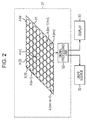
- Fig. 2 is a block diagram illustrating a configuration of the blood test apparatus.
- Fig. 3 is a diagram illustrating a configuration of a camera array.
- Fig. 4 is a diagram illustrating a configuration of the camera array.
- Fig. 5 is a diagram illustrating a configuration of a phase difference array.
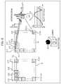
- Fig. 6 is a diagram illustrating a signal process.
- Fig. 7 is a diagram illustrating a method of designing the camera array.
- Fig. 8 is a flowchart illustrating a blood test process.
- Fig. 9 is a flowchart illustrating a manufacturing process of a phase difference array.
- Fig. 1 is a diagram illustrating a configuration example of an embodiment of a blood test apparatus employing an imaging device of the present technology.
- Fig. 2 is a block diagram illustrating a configuration of the
- Fig. 10 is a diagram illustrating a manufacturing process of the phase difference array.
- Fig. 11 is a diagram illustrating another configuration example of a phase difference array, which is a first modification.
- Fig. 12 is a diagram illustrating a configuration example of providing an area for capturing a color image, in an imaging element array, which is a second modification.
- Fig. 13 is a diagram illustrating a configuration example of further enlarging the area for capturing the color image, in the second modification.
- Fig. 14 is a diagram illustrating an example of generating a depth image by using a stereo image, which is a third modification.
- Fig. 15 is a diagram illustrating an example of obtaining a polarization state by using four types of the polarizers, which is a fourth modification.
- Fig. 16 is a diagram illustrating a configuration example of a general-purpose personal computer.
- Fig. 1 illustrates a configuration example of an embodiment of a blood test apparatus employing an imaging device of the present technology.
- the blood test apparatus 11 of Fig. 1 analyzes blood components in a blood vessel, based on a hyper spectral imaging (HSI), which is captured by a built-in imaging device, and measures and displays blood information such as an oxygen concentration, a lipid level, and a blood glucose level in blood.
- HSA hyper spectral imaging
- the blood test apparatus 11 is used while being worn like a watch along the arm 12 of a person who is the user so as to capture images of an artery 12a and a vein 12b inside the arm 12, and detect components contained in the blood from spectral reflectance data of the artery 12a and the vein 12b which are captured as the HSI 31.
- the blood test apparatus 11 includes, for example, a body 31, light sources 32-1 and 32-2, a display unit 33, and a connecting structure, for example in the form of a strap or belt 34.
- the blood test apparatus 11 has a configuration in which the body 31, the broadband light sources 32-1 and 32-2 such as halogen including a near-infrared light component, and the display unit 33 are provided on the belt 34 and are respectively electrically connected.
- the blood test apparatus 11 is secured to the arm 12 by being worn around the arm 12.
- the upper right part of Fig. 1 is a vertical cross-sectional view along an axis, with the longitudinal direction of the bone constituting the arm 12 with the axis, in a state where the blood test apparatus 11 is secured to the arm 12 by being worn around the arm 12 by using the belt 34.
- the HSI body 31 includes an imaging device that captures the HSI, is provided facing the arm 12 in a state where the blood test apparatus 11 is worn around the arm 12 by the belt 34, and captures a reflected image caused by the light emitted from the light sources 32-1 and 32-2 being reflected on the blood (artery blood) inside the artery 12a and the blood (vein blood) inside the vein 12b, inside the arm 12.
- the body 31 captures an image in which the artery 12a and the vein 12b are projected by, for example, light of a red wavelength to near-infrared light, in an image at a few millimeters under a skin, as illustrated in an image P12 in the lower left part of Fig. 1, corresponding to the image of arm 12 that is visible to the human eye by visible light as illustrated by the image P11 in the lower left part of Fig. 1.
- the artery 12a is assumed to be radial artery. Since the visibility of the artery 12a is not significantly good, the artery 12a may be located by extracting beating portions from a moving image.
- the body 31 spectrally analyzes the blood in the captured artery 12a and the vein 12b, measures the oxygen concentration, the lipid level, and the blood glucose level in the blood, and displays the measurement result and information corresponding to the measurement result, on the display unit 33.
- the body 31 includes a camera array 51 and a signal processing unit 52.
- the camera array 51 is configured with a plurality of, for example, m x n camera units that are arranged in the vertical direction and the horizontal direction. The same imaging area is cut and subjected to parallax correction such as an XY shift.
- the plurality of camera units capture interference images in which respective different wavelengths are emphasized, and output the interference images to the signal processing unit 52.
- Fig. 2 illustrates an example in which n camera units are arranged in the horizontal direction and m camera units are arranged in the vertical direction, in the camera array 51. Further, camera units A(1), A(2), A(3), ... A(n-1), and A(n) are sequentially arranged from the left to the right, respectively at a top row in the horizontal direction in Fig. 2. Further, even in the second row from the top, from the left to the right, camera units A(n+1), A(n+2), and A(n+3) are sequentially arranged.
- camera units A(mn-n+1), A(mn-n+2), and A(mn-n+3) are sequentially arranged, and a camera unit A(mn) is arranged in the rightmost column at the bottom row.
- the camera units are referred to as the camera units A(mn) described above, however, if the camera units are not distinguished, they are simply referred to as a camera unit A.
- the signal processing unit 52 generates an interferogram by reading image signals which are supplied from respective camera units A and includes interference images in which different wavelengths are emphasized, in units of pixels at the same position. Further, the signal processing unit 52 generates data configured with spectroscopic spectra, by performing a Fourier transform on the interferogram in units of pixels. Then, the signal processing unit 52 analyzes the necessary components such as the oxygen concentration, the lipid level, and the blood glucose level in the blood based on the generated data configured with spectroscopic spectra, and displays the analysis result on the display unit 33.
- the signal processing unit 52 causes the light sources 32-1 and 32-2 to emit light. Further, in the following description, if the light sources 32-1 and 32-2 are distinguished, they are simply referred to as the light source 32, and other components are assumed to be referred to in the same manner.
- the camera array 51 is configured with a lens array 71, a phase difference array 72, and a lens array 73, which are optical elements, and an imaging element array 74. Further, an apple image in Fig. 3 indicates an object. In other words, the light from the object propagates, in the order of the lens array 71, the phase difference array 72, the lens array 73, and the imaging element array 74.
- the lens array 71 is, for example, an array of objective lenses which are configured for the respective camera units of a focal length f, and the lens array 71 converts the incident light into cylindrical parallel light beams with respect to the respective camera units A, and inputs the parallel light beams to the phase difference array 72.
- an objective lens is provided for each camera unit A of the imaging element array, and each of the objective lenses creates a set of parallel light beams from the incident light for its respective camera unit A.
- the phase difference array 72 includes a plurality of phase difference elements that are defined by light shielding portions 72a.
- one phase difference element can be provided for each set of parallel light beams formed by the lens array 71.
- At least some of the elements of the phase difference array 72 include a filter that covers a portion of the parallel light beams incident from the lens array 71 with an object 72b having a predetermined refractive index.
- the elements of the phase difference array 72 associated with such an object 72b generate an optical path difference between the light beams passing through an area of the element covered with the object 72b and the light beams passing through an area of the element not converted with the object.
- the phase difference array 72 generates a phase difference corresponding to the optical path difference, and inputs the phase difference to the lens array 73 as an imaging lens array.
- the phase difference array 72 can include an element for or corresponding to each camera unit A.
- the phase differences are different for respective camera units A, and the phase difference may be zero in some cases.
- the camera unit A of which the phase difference becomes zero is referred to as, in particular, a camera unit A(C) in Fig. 2.
- the lens array 73 is an array of imaging lenses, and images the light flux with the phase difference added by the phase difference array 72, on the imaging element array 74, in units of the camera units A. In other words, the interference image is obtained.
- the imaging element array 74 is configured with complementary metal oxide semiconductor (CMOS) image sensors, captures different interference images in units of the camera units A, and outputs image signals of the captured interference images to the signal processing unit 52.
- CMOS complementary metal oxide semiconductor
- the imaging element array 74 is a single imaging element as a whole, and the camera units A described above are obtained by classifying the pixels on the imaging element, for each imaging element area for capturing a unit image for capturing the same imaging area.
- images are cut out for parallax correction, and subjected to an XY shift.
- the camera units A are not separate imaging elements, and a single imaging element area as a whole represents an area which is divided for each area of the predetermined number of pixels. That is, each of the camera units A includes a plurality of pixels.
- a monochrome imaging device without a color filter is used as the imaging element array 74.
- the lens array 71 as the objective lens array converts the incident light into parallel light beams of a range corresponding to respective camera units A(1) to A(mn).
- the phase difference array 72 causes a phase difference in the left and right parts of Fig. 4 by generating an optical path difference between some areas and the other areas of the parallel light beams by a filter-like object 72b of a predetermined refractive index, and inputs the light flux to the lens array 73 as the imaging lens array, by limiting the light flux by light shielding portions 72a configured with circular openings.
- the lens array 73 as the imaging lens array images the light flux added with the phase difference on the imaging element array 74, in units of the camera units A, and causes the imaging elements constituting the imaging element array 74 to capture interference images in which different wavelengths are emphasized corresponding to the added phase difference, in units of the camera units A.
- the objects 72b cause optical path differences corresponding to the thickness D of the object 72b, between the light in an area of an element covered with the object 72b and the light in the area of the element not covered with the object 72b, by covering a semicircular area with the object 72b, so as to generate interference images corresponding to the optical path differences.
- the interference images in which different wavelengths are emphasized are formed, by changing the thickness d of the object 72b with respect to the thickness of the remainder of the object 72.
- the thicknesses D of the object 72b which cause the phase differences are different for respective plurality of camera units A, and within the wavelength range to be measured, respective types of refractive index dispersion are assumed to be sufficiently small.
- the object 72b may also be a reflection type, for example, with a 45-degree incidence.
- the reflection type of a 45-degree incidence see Japanese Patent No. 5078004.
- Fig. 4 while the colors of the apples as the objects illustrated in the upper part in Fig. 4 are the same, the colors of the apples illustrated in the lower part in Fig. 4 are not the same, which indicate that the interference images in which different wavelengths are emphasized are captured by the respective camera units A.
- the number of pixels of respective camera units A included in the camera array 51 is assumed to be, for example, a QVGA (320 x 240 pixels). Further, for simplicity of explanation, it is assumed that the object is present at infinity and that the parallax for each camera unit is regarded as zero.
- pixels at a predetermined position in the interference images captured by respective camera units A constituting the camera array 51 are assumed to be the pixels at the same position within each of the interference images.
- the pixels P(1) to P(mn) at the same position in the respective camera units A(1) to A(mn) in Fig. 6 are read, and the distribution of the received light intensities of the pixels P(1) to P(mn) according to the phase difference corresponding to each image is the interferogram illustrated in the upper right part of Fig. 6.
- the horizontal axis represents a phase difference (Phase shift)
- the vertical axis represents the received light intensity (Intensity).
- the spectroscopic spectrum of each pixel corresponding to each image of the camera unit is obtained as illustrated in the lower right part of Fig. 6 by performing fast Fourier transform (FFT) on the interferogram which is obtained individually for each pixel position.
- FFT fast Fourier transform
- the horizontal axis represents a wavelength
- the vertical axis represents a reflectivity.
- spectroscopic spectrum for the image of QVGA (320 x 240 pixels) is obtained.
- the spectroscopic spectral data for each pixel of the image of QVGA (320 x 240 pixels) obtained in this manner is collectively referred to as an HSI Data cube.
- the image of an apple that is shown in the lower center part of Fig. 6 and a cube thereunder imitate the hyper spectral imaging (HSI) data cube configured with spectroscopic spectral data of each pixel in an image of which the object is an apple.
- HSI hyper spectral imaging
- CIS CMOS image sensor
- the spectral absorption characteristics of oxygenated hemoglobin (HbO 2 ) and reduced hemoglobin (Hb) in the blood are assumed as the measurement objects.
- the necessary measurement wavelength resolution is determined by the kurtosis of spectral characteristics.
- the horizontal axis represents a wavelength
- the vertical axis represents an absorption coefficient.
- the necessary wavelength resolution is assumed as an extreme value detection of near 750 nm of the reduced hemoglobin (Hb)
- the wavelength resolution (deltalambda) of about 25 nm is necessary from the sampling theorem.
- the necessary minimum wavelength is 600 nm
- a focused central wavelength is 665 nm which is the absorption extreme value of oxygenated hemoglobin (HbO 2 ).
- a phase difference array in which 8 x 8 64 rows of phase differences are formed at steps of 300 nm from 0 nm to 17.7 micrometers by the air conversion and 8 x 8 lens arrays are configured.
- phase difference is 300 nm by the air conversion in order to form such a phase difference array
- step S11 the signal processing unit 52 causes the light source 32 to emit light, and project the light to an area in which the artery 12a and the vein 12b of the arm 12 to be detected may be present.
- each lens in the array 71 provided in the preceding row in the light incident direction transmits the incident light as the light corresponding to each camera unit A, such that the incident light is converted into sets of parallel light that are incident on the phase difference array 72.
- step S13 the phase difference array 72 causes the light flux with the added phase difference to be incident on the lens array 73, with respect to each camera unit A.
- each lens in the array 73 provided in the subsequent row in the incident direction of light passes the respective light fluxes incident from the phase difference array 72 so as to be imaged on the imaging element array 74.
- step S15 the light receiving level of the interference image in each pixel of the imaging element array 74 is detected, and a pixel output which is a detection result is output to the signal processing unit 52, in units of the camera units A.
- step S16 the signal processing unit 52 generates the data constituting the interferogram in units of pixels, based on the pixel signal in units of the camera units A that is supplied from the imaging element array 74.
- step S17 the signal processing unit 52 performs Fast Fourier transform (FFT) on data obtained as an interferogram, and generates the hyper spectral imaging (HSI) data cube configured with data of the spectral spectrum for each pixel.
- FFT Fast Fourier transform
- HAI hyper spectral imaging
- step S18 signal processing unit 52 extracts the spectroscopic spectra of the artery portion and the vein portion from the HSI Data cube which is spectroscopic spectral data, analyzes predetermined components in the blood, and displays the analyzed values on the display unit 33 as the test results.
- the HSI can change whether the analysis target is artery blood or vein blood, or whether to use both data, depending on the contents to be analyzed.
- the signal processing unit 52 detects the oxygen concentration and the lipid level in the blood, based on the spectroscopic spectral data of the artery portion, detects the blood glucose level and the like, based on the spectroscopic spectral data of the vein portion, and displays the detected values on the display unit 33 as an analysis result.
- phase difference array 72 ⁇ With respect to manufacturing method>
- a manufacturing method of the phase difference array 72 will be described with reference to the flowchart of Fig. 9.
- step S31 as illustrated in a state B in Fig. 10, a chromium Cr layer 102 is formed by sputtering on the upper surface of the glass substrate 101, illustrated in a state A in Fig. 10.
- step S32 as illustrated in a state C in Fig. 10, a resist layer 103 is formed on the upper surface of the chromium Cr layer 102.
- step S33 as illustrated in a state D in Fig. 10, openings 104-1 to 104-4 of a circular aperture shape that determine the numerical aperture of the number of the above-mentioned camera array (numerical aperture (NA) or a F-value) are formed, by exposure and development. Further, the example of the case of openings 104-1 to 104-4 of four is illustrated, but it is only an example, and in the following, the case of openings 104-1 to 104-4 of four will be described.
- NA numerical aperture
- step S34 as illustrated in a state E in Fig. 10, the chromium Cr layer 102 is subjected to a transfer machining, by dry etching so as to form openings 104'-1 to 104'-4. In addition, thereafter, without being illustrated, the resist layer 103 is removed.
- step S35 as illustrated in a state F in Fig. 10, for the device protection in the back process, a silicon oxide film 105 and the like are formed.
- step S36 as illustrated in a state G in Fig. 10, the glass substrate 101 is inverted. Further, as illustrated in a state H in Fig. 10, a resist layer 106 is formed on the back surface of the glass substrate 101. Further, the resist layer 106 is exposed using a grayscale reticle (gray-scale photomask). For the exposure by grayscale reticle, see Japanese Patent No. 429643 of the applicant.
- step S37 as illustrated in a state I in Fig. 10, protrusions 106a to 106d are formed in the resist layer 106 by the development.
- step S38 as illustrated in a state J in Fig. 10, protrusions 101a to 101d corresponding to the object 72b are formed on the glass substrate by dry etching. Thereafter, if the oxide film 105 is removed, the phase difference array 72 is completed. In other words, the protrusions 101a to 101d are formed as the semicircular object 72b in Fig. 5.
- step S37 when steps 106a to 106d are formed in the resist layer 106, the process is terminated, and the process of step S38 is skipped.
- protrusions 106a to 106d are formed as a semicircular object 72b in Fig. 5.
- the phase difference array 72 can be processed in a semiconductor process without using a special material, it becomes possible to realize a cost reduction of the camera array 51. Further, since it is possible to process a signal by area division in the imaging element, by forming the array structure on a common imaging element, the imaging element can substantially be a single element, therefore it is possible to realize cost reduction, and an increase in processing speed.
- an area where the object 72b' is not provided may be set in the center part so as to provide the object 72b' in a cylindrical shape, in the area of each camera unit A.
- areas other than the area where the non-phase difference array 151 is provided in the imaging element array 74 are used for the process for obtaining the HSI Data cube, and the area where the non-phase difference array 151 is provided is used for the process of generating a color image.
- a non-phase difference array 171 is provided in an area for generating a color image of the area of 2 x 2 times the area of the camera unit in the horizontal direction and vertical direction, as illustrated in the right part of Fig. 13, a color filter 181 of the same size may be provided.
- the color filter may be one other than the three colors of RGB, and it is also possible to capture the monochrome image containing only luminance.
- the number of pixels of SXGA (1280 x 960 pixels) is allocated as necessary, it is possible to provide a general color image of an HD quality.
- ⁇ Third modification> The description has been made about examples of acquiring the HSI Data cube, or the HSI Data cube and the color image, and respective camera units are provided in the camera array 51 while the respective ends are separated in the horizontal direction and vertical direction, but stereo cameras as the camera units are provided in the respective ends, therefore it is possible to obtain a so-called depth image including depth information regarding depth distances in units of pixels in the camera unit. This makes it possible to simultaneously obtain the spectral information and depth information of the object.
- the thicknesses D of the objects 72b in the phase difference array 72 continuously and sequentially change towards the right direction in the horizontal direction.
- the phase difference array 72R and the phase difference array 72L are in the height order of the thickness D, they are adjacent to each other, and thus the amount of change in phase difference is significantly small. Therefore, the influence on the depth distance by the parallax is very small.
- a polarizer array 201 is provided between the phase difference array 72 and the lens array 73, therefore it is possible to obtain polarization information.
- the phase difference array 72 which is the same optical path is set in a unit of a range of 2 x 2 pieces.
- polarizers which differ by 45 degrees are disposed in 2 x 2 camera units present in the area of the phase difference array 72 which is the same optical path.
- the polarizer In general, in the polarizer, Stokes parameters for representing the polarization state or Jones vectors are obtained by analyzing the polarization components of four orientations. Therefore, the Stokes parameters or the Jones vectors of each pixel are obtained, based on information regarding the camera units of the polarizers of the four orientations in the area of the phase difference array 72 which is the same optical path, by, for example, the signal processing unit 52, therefore it is possible to obtain the polarization state in units of pixels.
- the size of the camera unit A is a QVGA pixel
- the polarizing sheet which is formed by a general rolling process is cut to the size of the camera unit area, such as the size of about a 1 mm square, and the orientations of the cut sheets are changed, therefore it is possible to realize the configuration illustrated in Fig. 15.
- the series of processes described above can be performed by hardware, but can also be performed by software.
- programs constituting the software are installed in a dedicated hardware built-in computer, or for example, a general-purpose personal computer capable of executing various functions by installing various programs, from the recording medium.
- Fig. 16 is a diagram illustrating a configuration example of a general-purpose personal computer.
- a central processing unit (CPU) 1001 is built into the personal computer.
- the CPU 1001 is connected to an input and output interface 1005 through a bus 1004.
- a read only memory (ROM) 1002 and a random access memory (RAM) 1003 are connected to the bus 1004.
- ROM read only memory
- RAM random access memory
- An input unit 1006 including input devices such as a keyboard and a mouse through which the user inputs operation commands, an output unit 1007 that outputs processing operation screens and images resulting from processes on a display device, a storage unit 1008 including a hard disk drive that stores programs and various types of data, and a communication unit 1009 including a local area network (LAN) adapter that executes a communication process through a network represented by the Internet are connected to the input and output interface 1005.
- LAN local area network
- a drive 1010 that reads and write data to a removable media 1011 such as a magnetic disk (including a flexible disk), an optical disk (including a compact disc-read only memory (CD-ROM), and a digital versatile disc (DVD)), a magneto-optical disk (including a mini disc (MD)), or a semiconductor memory is connected to the input and output interface 1005.
- a removable media 1011 such as a magnetic disk (including a flexible disk), an optical disk (including a compact disc-read only memory (CD-ROM), and a digital versatile disc (DVD)), a magneto-optical disk (including a mini disc (MD)), or a semiconductor memory is connected to the input and output interface 1005.
- the CPU 1001 performs various processes according to the program stored in the ROM 1002, or the program which is read from the removable media 1011 such as the magnetic disk, the optical disk, the magneto-optical disk, or the semiconductor memory and installed in the storage unit 1008, and read from the storage unit 1008 and loaded in the RAM 1003.
- the RAM 1003 appropriately stores data and the like necessary for the CPU 1001 to execute various processes.
- the program that the computer (CPU 1001) executes may be provided by being recorded, for example, on the removable media 1011 as package media or the like. Further, the program may be provided through a wired or wireless transmission medium such as a local area network, the Internet, and digital satellite broadcasting.
- the program may be installed in the storage unit 1008, through the input and output interface 1005, by mounting the removable media 1011 in the drive 1010. Further, the program may be received by the communication unit 1009 and installed in the storage unit 1008, through a wired or wireless transmission medium. Alternatively, the program may be installed in advance in the ROM 1002 or the storage unit 1008.
- program that the computer executes may be a program in which processes are performed chronologically in the order described in the specification, or a program in which processes are performed in parallel or at a necessary timing, such as when a call is made.
- a system refers to the collection of a plurality of components (devices, modules (parts), and the like), and it does not matter whether all the components are in the same housing.
- a plurality of devices which are housed in separate housings and connected through a network and one device including a plurality of modules which are housed in one housing are both the system.
- the present technology may take a cloud computing configuration in which one function is shared by a plurality of devices to be processed jointly through the network.
- each step described in the flowchart described above may be performed by being shared by a plurality of devices, as well as by one device.
- one step contains a plurality of processes
- a plurality of processes included in the one step may be performed by being shared by a plurality of devices, as well as by one device.
- An imaging device comprising: a phase difference array with a plurality of elements, wherein the phase difference array is configured to provide different optical paths for light included within at least some of a plurality of sets of light beams; and an imaging element array including a plurality of imaging elements, wherein at least one of the imaging elements is configured to receive one of the sets of light beams from the phase difference array.
- the imaging device according to (1) or (2) further comprising: an objective lens array, wherein the objective lens array includes a plurality of objective lenses, and wherein the objective lens array is configured to provide the plurality of sets of light beams to the phase difference array.
- an imaging lens array including a plurality of imaging lenses wherein the imaging lens array is positioned between the phase difference array and the imaging element array.
- the imaging device (11) The imaging device according to (10), wherein the imaging lenses of the imaging lens array image the plurality of sets of light beams onto at least some of the imaging elements. (12) The imaging device according to any one of (1) to (11), wherein each of the imaging elements includes a plurality of pixels. (13) The imaging device according to any one of (1) to (12), wherein light from a first area of an imaged object is included in a first one of the sets of light beams, and wherein light from the first area of the imaged object is included in a second one of the sets of light beams.
- a detection apparatus comprising: a connecting structure; a light source, wherein the light source is connected to the connecting structure; an enclosure, wherein the enclosure is connected to the connecting structure, and wherein the enclosure includes: a phase difference array with a plurality of elements, wherein the phase difference array is configured to provide different optical paths for light included within at least some of a plurality of sets of light beams; an imaging element array including a plurality of imaging elements, wherein at least one of the imaging elements is configured to receive one of the sets of light beams from the phase difference array; a display, wherein the display is connected to the connecting structure, and wherein the display is operable to display detection information generated from data provided by the imaging element array.
- the detection apparatus further comprising: an objective lens array, wherein the object lens array includes a plurality of objective lenses, and wherein the objective lens array is configured to provide the plurality of sets of light beams to the phase difference array.
- the plurality of sets of light beams provided by the objective lens array are cylindrical parallel light beams.
- the detection apparatus according to any one of (14) to (16), wherein at least some of the elements of the phase difference array are configured to generate an optical path difference between a first portion of a light beam incident on a first part of the element and a second portion of the light beam incident on a second part of the element.
- the detection apparatus according to any one of (14) to (21), wherein the enclosure further includes: a polarizer array, wherein the polarizer array includes four different types of polarizers that differ from one another by at least 45 degrees.
- the connecting structure is a belt.
- a method for detecting a physical property comprising: emitting light onto an object; receiving light from the object at a plurality of phase difference elements included in a phase difference array, wherein at least some of the phase difference elements generate a phase difference from the light incident on the phase difference elements; receiving light from the phase difference elements at an imaging element array; displaying information obtained from hyperspectral imaging (HIS) data based on output signals of the imaging element array.
- HIS hyperspectral imaging
- An imaging device including an imaging element array that captures a same imaging area, as a plurality of unit images; and a phase difference array that causes respective different optical path differences in a portion of respective imaging areas of the plurality of unit images which are captured by the imaging element array.
- the phase difference array includes a filter that causes the optical path differences in a semicircular shape for the respective imaging areas, and wherein the optical path differences are different for the respective imaging areas of the plurality of unit images.
- a filter constituting the phase difference array has sufficiently small refractive index dispersion in a wavelength range to be measured, or is a reflection type with incidence of 45 degrees.
- the imaging device according to any one of (25) to (27), wherein the imaging element array captures images caused for the respective imaging areas by the phase difference array, as interference images.
- the imaging device further including a signal processing unit that generates an interferogram from output data of pixels at the same position of the respective interference images that are captured for the respective imaging areas by the imaging element array, and calculates spectral characteristics of the respective pixels as hyper spectral imaging (HSI) data cubes by performing Fourier transform on the interferogram.
- HSA hyper spectral imaging
- imaging device any one of (25) to (30), wherein optical elements in the respective imaging areas of the imaging element array are formed at a wafer level, wherein a lens array in a preceding row, a phase difference array, and a lens array in a subsequent row are defined as the optical elements, and wherein the imaging device further includes a camera array configured with the optical elements and the imaging element array.
- the imaging element array includes at least one or more imaging element areas for capturing a unit image of a monochrome image or an image generated by an RGB color filter, which does not have a phase difference and is not an interference image.
- the imaging device (32), wherein the imaging element area is 4n (n is an integer of 1 or greater) times the imaging area of the unit image for the hyper spectral imaging (HSI) data cube. (34) The imaging device according to any one of (25) to (33), wherein one set of polarizers of four orientations is arranged for respective four imaging areas in the phase difference array, with respect to the camera array, and wherein the signal processing unit calculates a Stokes parameter or a Jones vector of each image point in the unit image, based on pixel signals of the imaging areas of the one set of polarizers.
- An imaging method of an imaging device including an imaging element array that captures a same imaging area, as a plurality of unit images, and a phase difference array that causes respective different optical path differences in a portion of respective imaging areas of the plurality of unit images which are captured by the imaging element array, the method causing the imaging element array to capture the same imaging area, as the plurality of unit images, and the phase difference array to cause the respective different optical path differences in a portion of respective imaging areas of the plurality of unit images which are captured by the imaging element array.
- Blood test apparatus 12 Arm 12a Artery 12b Vein 31 Body 32, 32-1, 32-2 Light source 33 Display unit 34 Belt 51 Camera array 52 Signal processing unit 71 Lens array 72 Phase difference array 72a Light shielding portion 72b Object 73 Lens array 74 Imaging element array
Landscapes
- Physics & Mathematics (AREA)
- Spectroscopy & Molecular Physics (AREA)
- General Physics & Mathematics (AREA)
- Health & Medical Sciences (AREA)
- Life Sciences & Earth Sciences (AREA)
- General Health & Medical Sciences (AREA)
- Pathology (AREA)
- Engineering & Computer Science (AREA)
- Biomedical Technology (AREA)
- Heart & Thoracic Surgery (AREA)
- Medical Informatics (AREA)
- Molecular Biology (AREA)
- Surgery (AREA)
- Animal Behavior & Ethology (AREA)
- Biophysics (AREA)
- Public Health (AREA)
- Veterinary Medicine (AREA)
- Optics & Photonics (AREA)
- Analytical Chemistry (AREA)
- Biochemistry (AREA)
- Immunology (AREA)
- Chemical & Material Sciences (AREA)
- Emergency Medicine (AREA)
- Investigating Or Analysing Materials By Optical Means (AREA)
- Spectrometry And Color Measurement (AREA)
- Measurement Of The Respiration, Hearing Ability, Form, And Blood Characteristics Of Living Organisms (AREA)
- Traffic Control Systems (AREA)
- Air Bags (AREA)
- Vehicle Body Suspensions (AREA)
Abstract
Description
This application claims the benefit of Japanese Priority Patent Application JP 2014-131808 filed June 26, 2014, the entire contents of which are incorporated herein by reference.
Fig. 1 illustrates a configuration example of an embodiment of a blood test apparatus employing an imaging device of the present technology. The
Next, the configuration of the
Next, the configuration of the
Next, with reference to Fig. 6, a signal processing method for generating an HSI from the interference images captured by the respective plurality of camera units A in the
Next, examples of the number of camera units A (the number of a plurality of images which are set in the
Next, a blood test process using the blood test apparatus of Fig. 1 will be described with reference to the flowchart of Fig. 8.
Next, a manufacturing method of the
In the above, the description has been made about the example of providing the optical path difference by the
In the above, the description has been made about examples of acquiring only the HSI by the
The description has been made about examples of acquiring the HSI Data cube, or the HSI Data cube and the color image, and respective camera units are provided in the
In the above, the description has been made about the example of simultaneously imaging the HSI image and the depth image, but it may be possible to obtain polarization information.
(1) An imaging device, comprising:
a phase difference array with a plurality of elements, wherein the phase difference array is configured to provide different optical paths for light included within at least some of a plurality of sets of light beams; and
an imaging element array including a plurality of imaging elements, wherein at least one of the imaging elements is configured to receive one of the sets of light beams from the phase difference array.
(2) The imaging device according to (1) or (2), further comprising: an objective lens array, wherein the objective lens array includes a plurality of objective lenses, and wherein the objective lens array is configured to provide the plurality of sets of light beams to the phase difference array.
(3) The imaging device according to (2), wherein the plurality of sets of light beams provided by the objective lens array are cylindrical parallel light beams.
(4) The imaging device according to any one of (1) to (3), wherein at least some of the elements of the phase difference array are configured to generate an optical path difference between a first portion of a light beam incident on a first part of the element and a second portion of the light beam incident on a second part of the element.
(5) The imaging device according to (4), wherein for the at least some of the elements of the phase difference array a thickness of the first part of the element is different than a thickness of the second part of the element.
(6) The imaging element according to (5), wherein the first part of the element has a semicircular area.
(7) The imaging device according to (5), wherein the first part of the element has a cylindrical area.
(8) The imaging device according to (5), wherein the thickness of the first part of the element increases from an element at a first end of the phase difference array to an element at a second end of the phase difference array.
(9) The imaging device according to any one of (1) to (8), further comprising: a polarizer array, wherein the polarizer array includes four different types of polarizers that differ from one another by at least 45 degrees.
(10) The imaging device according to any one of (1) to (9), further comprising: an imaging lens array including a plurality of imaging lenses, wherein the imaging lens array is positioned between the phase difference array and the imaging element array.
(11) The imaging device according to (10), wherein the imaging lenses of the imaging lens array image the plurality of sets of light beams onto at least some of the imaging elements.
(12) The imaging device according to any one of (1) to (11), wherein each of the imaging elements includes a plurality of pixels.
(13) The imaging device according to any one of (1) to (12), wherein light from a first area of an imaged object is included in a first one of the sets of light beams, and wherein light from the first area of the imaged object is included in a second one of the sets of light beams.
(14) A detection apparatus, comprising: a connecting structure; a light source, wherein the light source is connected to the connecting structure; an enclosure, wherein the enclosure is connected to the connecting structure, and wherein the enclosure includes: a phase difference array with a plurality of elements, wherein the phase difference array is configured to provide different optical paths for light included within at least some of a plurality of sets of light beams; an imaging element array including a plurality of imaging elements, wherein at least one of the imaging elements is configured to receive one of the sets of light beams from the phase difference array; a display, wherein the display is connected to the connecting structure, and wherein the display is operable to display detection information generated from data provided by the imaging element array.
(15) The detection apparatus according to (14), further comprising: an objective lens array, wherein the object lens array includes a plurality of objective lenses, and wherein the objective lens array is configured to provide the plurality of sets of light beams to the phase difference array.
(16) The detection apparatus according to (15), wherein the plurality of sets of light beams provided by the objective lens array are cylindrical parallel light beams.
(17) The detection apparatus according to any one of (14) to (16), wherein at least some of the elements of the phase difference array are configured to generate an optical path difference between a first portion of a light beam incident on a first part of the element and a second portion of the light beam incident on a second part of the element.
(18) The detection apparatus according to (17), wherein for at least some of the elements of the phase difference array a thickness of the first part of the element of the phase difference array is different than a thickness of the second part of the element of the phase difference array.
(19) The detection apparatus according to (18), wherein the first part of the element has a semicircular area.
(20) The detection apparatus according to (18), wherein the first part of the element has a cylindrical area.
(21) The detection apparatus according to (18), wherein a thickness of the first part of the element increases from an element at a first end of the phase difference array to an element at a second end of the phase difference array.
(22) The detection apparatus according to any one of (14) to (21), wherein the enclosure further includes: a polarizer array, wherein the polarizer array includes four different types of polarizers that differ from one another by at least 45 degrees.
(23) The detection apparatus according to any one of (14) to (22), wherein the connecting structure is a belt.
(24) A method for detecting a physical property, comprising: emitting light onto an object; receiving light from the object at a plurality of phase difference elements included in a phase difference array, wherein at least some of the phase difference elements generate a phase difference from the light incident on the phase difference elements; receiving light from the phase difference elements at an imaging element array; displaying information obtained from hyperspectral imaging (HIS) data based on output signals of the imaging element array.
(25) An imaging device including
an imaging element array that captures a same imaging area, as a plurality of unit images; and
a phase difference array that causes respective different optical path differences in a portion of respective imaging areas of the plurality of unit images which are captured by the imaging element array.
(26) The imaging device according to (25),
wherein the phase difference array includes a filter that causes the optical path differences in a semicircular shape for the respective imaging areas, and
wherein the optical path differences are different for the respective imaging areas of the plurality of unit images.
(27) The imaging device according to (25) or (26),
wherein a filter constituting the phase difference array has sufficiently small refractive index dispersion in a wavelength range to be measured, or is a reflection type with incidence of 45 degrees.
(28) The imaging device according to any one of (25) to (27),
wherein the imaging element array captures images caused for the respective imaging areas by the phase difference array, as interference images.
(29) The imaging device according to (28), further including
a signal processing unit that generates an interferogram from output data of pixels at the same position of the respective interference images that are captured for the respective imaging areas by the imaging element array, and calculates spectral characteristics of the respective pixels as hyper spectral imaging (HSI) data cubes by performing Fourier transform on the interferogram.
(30) The imaging device according to (29),
wherein a phase difference of the phase difference array is set so as to monotonically increase or monotonically decrease, in a predetermined direction of the imaging areas which are arranged consecutively, and
wherein the signal processing unit generates a depth image by using an image of an imaging area at one end and an image of an imaging area at the other end, in the predetermined direction of the phase difference array, as a stereo image.
(31) The imaging device according to any one of (25) to (30),
wherein optical elements in the respective imaging areas of the imaging element array are formed at a wafer level,
wherein a lens array in a preceding row, a phase difference array, and a lens array in a subsequent row are defined as the optical elements, and
wherein the imaging device further includes a camera array configured with the optical elements and the imaging element array.
(32) The imaging device according to (31),
wherein the imaging element array includes at least one or more imaging element areas for capturing a unit image of a monochrome image or an image generated by an RGB color filter, which does not have a phase difference and is not an interference image.
(33) The imaging device according to (32),
wherein the imaging element area is 4n (n is an integer of 1 or greater) times the imaging area of the unit image for the hyper spectral imaging (HSI) data cube.
(34) The imaging device according to any one of (25) to (33),
wherein one set of polarizers of four orientations is arranged for respective four imaging areas in the phase difference array, with respect to the camera array, and
wherein the signal processing unit calculates a Stokes parameter or a Jones vector of each image point in the unit image, based on pixel signals of the imaging areas of the one set of polarizers.
(35) An imaging method of an imaging device, the imaging device including an imaging element array that captures a same imaging area, as a plurality of unit images, and a phase difference array that causes respective different optical path differences in a portion of respective imaging areas of the plurality of unit images which are captured by the imaging element array, the method causing
the imaging element array to capture the same imaging area, as the plurality of unit images, and
the phase difference array to cause the respective different optical path differences in a portion of respective imaging areas of the plurality of unit images which are captured by the imaging element array.
12 Arm
12a Artery
12b Vein
31 Body
32, 32-1, 32-2 Light source
33 Display unit
34 Belt
51 Camera array
52 Signal processing unit
71 Lens array
72 Phase difference array
72a Light shielding portion
72b Object
73 Lens array
74 Imaging element array
Claims (24)
- An imaging device, comprising:
a phase difference array with a plurality of elements, wherein the phase difference array is configured to provide different optical paths for light included within at least some of a plurality of sets of light beams; and
an imaging element array including a plurality of imaging elements, wherein at least one of the imaging elements is configured to receive one of the sets of light beams from the phase difference array. - The imaging device of claim 1, further comprising:
an objective lens array, wherein the objective lens array includes a plurality of objective lenses, and wherein the objective lens array is configured to provide the plurality of sets of light beams to the phase difference array. - The imaging device of claim 2, wherein the plurality of sets of light beams provided by the objective lens array are cylindrical parallel light beams.
- The imaging device of claim 1, wherein at least some of the elements of the phase difference array are configured to generate an optical path difference between a first portion of a light beam incident on a first part of the element and a second portion of the light beam incident on a second part of the element.
- The imaging device of claim 4, wherein for the at least some of the elements of the phase difference array a thickness of the first part of the element is different than a thickness of the second part of the element.
- The imaging element of claim 5, wherein the first part of the element has a semicircular area.
- The imaging device of claim 5, wherein the first part of the element has a cylindrical area.
- The imaging device of claim 5, wherein the thickness of the first part of the element increases from an element at a first end of the phase difference array to an element at a second end of the phase difference array.
- The imaging device of claim 1, further comprising:
a polarizer array, wherein the polarizer array includes four different types of polarizers that differ from one another by at least 45 degrees. - The imaging device of claim 1, further comprising:
an imaging lens array including a plurality of imaging lenses, wherein the imaging lens array is positioned between the phase difference array and the imaging element array. - The imaging device of claim 10, wherein the imaging lenses of the imaging lens array image the plurality of sets of light beams onto at least some of the imaging elements.
- The imaging device of claim 1, wherein each of the imaging elements includes a plurality of pixels.
- The imaging device of claim 1, wherein light from a first area of an imaged object is included in a first one of the sets of light beams, and wherein light from the first area of the imaged object is included in a second one of the sets of light beams.
- A detection apparatus, comprising:
a connecting structure;
a light source, wherein the light source is connected to the connecting structure;
an enclosure, wherein the enclosure is connected to the connecting structure, and wherein the enclosure includes:
a phase difference array with a plurality of elements, wherein the phase difference array is configured to provide different optical paths for light included within at least some of a plurality of sets of light beams;
an imaging element array including a plurality of imaging elements, wherein at least one of the imaging elements is configured to receive one of the sets of light beams from the phase difference array;
a display, wherein the display is connected to the connecting structure, and wherein the display is operable to display detection information generated from data provided by the imaging element array. - The detection apparatus of claim 14, further comprising:
an objective lens array, wherein the object lens array includes a plurality of objective lenses, and wherein the objective lens array is configured to provide the plurality of sets of light beams to the phase difference array. - The detection apparatus of claim 15, wherein the plurality of sets of light beams provided by the objective lens array are cylindrical parallel light beams.
- The detection apparatus of claim 14, wherein at least some of the elements of the phase difference array are configured to generate an optical path difference between a first portion of a light beam incident on a first part of the element and a second portion of the light beam incident on a second part of the element.
- The detection apparatus of claim 17, wherein for at least some of the elements of the phase difference array a thickness of the first part of the element of the phase difference array is different than a thickness of the second part of the element of the phase difference array.
- The detection apparatus of claim 18, wherein the first part of the element has a semicircular area.
- The detection apparatus of claim 18, wherein the first part of the element has a cylindrical area.
- The detection apparatus of claim 18, wherein a thickness of the first part of the element increases from an element at a first end of the phase difference array to an element at a second end of the phase difference array.
- The detection apparatus of claim 14, wherein the enclosure further includes:
a polarizer array, wherein the polarizer array includes four different types of polarizers that differ from one another by at least 45 degrees. - The detection apparatus of claim 14, wherein the connecting structure is a belt.
- A method for detecting a physical property, comprising:
emitting light onto an object;
receiving light from the object at a plurality of phase difference elements included in a phase difference array, wherein at least some of the phase difference elements generate a phase difference from the light incident on the phase difference elements;
receiving light from the phase difference elements at an imaging element array;
displaying information obtained from hyperspectral imaging (HIS) data based on output signals of the imaging element array.
Priority Applications (4)
| Application Number | Priority Date | Filing Date | Title |
|---|---|---|---|
| EP15735749.2A EP3161433A2 (en) | 2014-06-26 | 2015-06-17 | Imaging device and method |
| US15/313,173 US11054304B2 (en) | 2014-06-26 | 2015-06-17 | Imaging device and method |
| CN201580027058.8A CN106456070B (en) | 2014-06-26 | 2015-06-17 | Image forming apparatus and method |
| KR1020167032066A KR102425589B1 (en) | 2014-06-26 | 2015-06-17 | Imaging device and method |
Applications Claiming Priority (2)
| Application Number | Priority Date | Filing Date | Title |
|---|---|---|---|
| JP2014131808A JP6524617B2 (en) | 2014-06-26 | 2014-06-26 | Imager and method |
| JP2014-131808 | 2014-06-26 |
Publications (2)
| Publication Number | Publication Date |
|---|---|
| WO2015198562A2 true WO2015198562A2 (en) | 2015-12-30 |
| WO2015198562A3 WO2015198562A3 (en) | 2016-03-24 |
Family
ID=53525228
Family Applications (1)
| Application Number | Title | Priority Date | Filing Date |
|---|---|---|---|
| PCT/JP2015/003023 WO2015198562A2 (en) | 2014-06-26 | 2015-06-17 | Imaging device and method |
Country Status (7)
| Country | Link |
|---|---|
| US (1) | US11054304B2 (en) |
| EP (1) | EP3161433A2 (en) |
| JP (1) | JP6524617B2 (en) |
| KR (1) | KR102425589B1 (en) |
| CN (1) | CN106456070B (en) |
| TW (1) | TWI693391B (en) |
| WO (1) | WO2015198562A2 (en) |
Cited By (2)
| Publication number | Priority date | Publication date | Assignee | Title |
|---|---|---|---|---|
| US20170184449A1 (en) * | 2014-06-26 | 2017-06-29 | Sony Corporation | Imaging device and method |
| US20220268632A1 (en) * | 2019-08-21 | 2022-08-25 | Arizona Board Of Regents On Behalf Of The University Of Arizona | Reconfigurable polarization imaging system |
Families Citing this family (17)
| Publication number | Priority date | Publication date | Assignee | Title |
|---|---|---|---|---|
| US10855971B2 (en) | 2015-09-16 | 2020-12-01 | HashD, Inc. | Systems and methods of creating a three-dimensional virtual image |
| JP6744005B2 (en) * | 2016-03-02 | 2020-08-19 | 国立大学法人 香川大学 | Spectrometer |
| CN107192349B (en) | 2016-03-14 | 2020-10-16 | 松下知识产权经营株式会社 | Optical detection device |
| EP3541285B1 (en) | 2016-11-16 | 2020-06-24 | Koninklijke Philips N.V. | Apparatus for generating multi energy data from phase contrast imaging data |
| US11354818B2 (en) * | 2017-06-21 | 2022-06-07 | Sony Corporation | Medical imaging system, method and computer program product |
| CN107274400B (en) | 2017-06-21 | 2021-02-12 | 歌尔光学科技有限公司 | Space positioning device, positioning processing method and device, and virtual reality system |
| KR102064593B1 (en) * | 2017-09-27 | 2020-02-11 | 연세대학교 산학협력단 | Topology for surface |
| JP6831506B2 (en) * | 2017-11-16 | 2021-02-17 | 日本電気株式会社 | Light measuring device and light measuring method |
| JP2019132605A (en) * | 2018-01-29 | 2019-08-08 | 株式会社Jvcケンウッド | Spectrometer |
| JP6969413B2 (en) * | 2018-01-29 | 2021-11-24 | 株式会社Jvcケンウッド | Spectrometer |
| CN109061638B (en) * | 2018-06-02 | 2022-06-10 | 苏州威陌电子信息科技有限公司 | Phased array close-range digital imaging method |
| CN109528313B (en) * | 2018-10-12 | 2021-04-20 | 合刃科技(武汉)有限公司 | Spectrum three-dimensional positioning and identifying system |
| CN111836001A (en) * | 2019-04-15 | 2020-10-27 | 何三玄 | Anti-terrorism photography system |
| CN111006765B (en) * | 2019-12-27 | 2024-01-30 | 中国科学院西安光学精密机械研究所 | Compact snapshot type spectrum imaging device and method based on micro-interference array |
| CN112113661B (en) * | 2020-07-29 | 2021-07-13 | 西安交通大学 | Deep learning type snapshot spectrum imaging device and detection method thereof |
| JPWO2022264487A1 (en) * | 2021-06-15 | 2022-12-22 | ||
| CN114041789B (en) * | 2021-10-29 | 2023-09-01 | 中国科学院西安光学精密机械研究所 | High-integration portable polarization regulation blood sugar measurement device and method |
Citations (2)
| Publication number | Priority date | Publication date | Assignee | Title |
|---|---|---|---|---|
| JPH029643A (en) | 1988-06-28 | 1990-01-12 | Nec Corp | Thermal recording control |
| JPH0578004B2 (en) | 1983-06-22 | 1993-10-27 | Fujitsu Ltd |
Family Cites Families (18)
| Publication number | Priority date | Publication date | Assignee | Title |
|---|---|---|---|---|
| US5736958A (en) * | 1990-10-29 | 1998-04-07 | Essex Corporation | Image synthesis using time sequential holography |
| DE4300700A1 (en) * | 1992-01-14 | 1993-07-29 | Boreal Laser Inc | Carbon di:oxide plate laser group arrangement - has channel between wave-conducting electrode surfaces subdivided into multiple parallel laser resonators |
| US20030016901A1 (en) * | 2001-06-21 | 2003-01-23 | Cormack Robert H. | Selectively enabled delay elements for interferometers |
| WO2006018897A1 (en) * | 2004-08-20 | 2006-02-23 | Mitsubishi Denki Kabushiki Kaisha | Laser phase difference detector and laser phase controller |
| KR20060025402A (en) * | 2004-09-16 | 2006-03-21 | 삼성전자주식회사 | Optical system for multi-channel sample analyzer and analyzer employing the same |
| DE102006025122A1 (en) * | 2005-05-31 | 2006-12-07 | Yokogawa Electric Corporation, Musashino | Device for measuring an optical characteristic |
| TWI295369B (en) * | 2005-09-13 | 2008-04-01 | Applied Res Lab | Inspection method and device for deformation of lens |
| JP5018222B2 (en) * | 2007-05-09 | 2012-09-05 | セイコーエプソン株式会社 | Directional display |
| JP5120873B2 (en) * | 2007-06-15 | 2013-01-16 | 国立大学法人 香川大学 | Spectroscopic measurement apparatus and spectral measurement method |
| JP5078004B2 (en) | 2007-06-15 | 2012-11-21 | 国立大学法人 香川大学 | Spectroscopic measurement apparatus and spectral measurement method |
| CN101455559B (en) * | 2008-12-15 | 2011-06-29 | 深圳先进技术研究院 | Human infrared high spectrum imaging method and system |
| US9188478B2 (en) * | 2012-02-09 | 2015-11-17 | Bossa Nova Technologies, Llc | Multi-channel laser interferometric method and apparatus for detection of ultrasonic motion from a surface |
| JP2014010046A (en) * | 2012-06-29 | 2014-01-20 | Seiko Epson Corp | Substance detection device and wrist watch type body fat burning measurement device |
| CN102846312B (en) * | 2012-09-27 | 2014-03-05 | 华东师范大学 | Multi-dimensional imaging detector and data inversion method thereof |
| CN103829926A (en) * | 2012-11-21 | 2014-06-04 | 西安中科麦特电子技术设备有限公司 | Polarization spectrum imaging system |
| CN103349553B (en) * | 2013-08-01 | 2015-01-28 | 赵巍 | Double-wavelength differential near-infrared non-invasive glucose meter |
| US20150281538A1 (en) * | 2014-03-25 | 2015-10-01 | Semiconductor Components Industries, Llc | Multi-array imaging systems and methods |
| JP6524617B2 (en) * | 2014-06-26 | 2019-06-05 | ソニー株式会社 | Imager and method |
-
2014
- 2014-06-26 JP JP2014131808A patent/JP6524617B2/en active Active
-
2015
- 2015-05-22 TW TW104116555A patent/TWI693391B/en active
- 2015-06-17 US US15/313,173 patent/US11054304B2/en active Active
- 2015-06-17 CN CN201580027058.8A patent/CN106456070B/en active Active
- 2015-06-17 EP EP15735749.2A patent/EP3161433A2/en not_active Withdrawn
- 2015-06-17 KR KR1020167032066A patent/KR102425589B1/en active IP Right Grant
- 2015-06-17 WO PCT/JP2015/003023 patent/WO2015198562A2/en active Application Filing
Patent Citations (2)
| Publication number | Priority date | Publication date | Assignee | Title |
|---|---|---|---|---|
| JPH0578004B2 (en) | 1983-06-22 | 1993-10-27 | Fujitsu Ltd | |
| JPH029643A (en) | 1988-06-28 | 1990-01-12 | Nec Corp | Thermal recording control |
Non-Patent Citations (2)
| Title |
|---|
| B. GEELEN: "A Snapshot Multispectral mager with Integrated, Tiled Filters and Optical Duplication", SPIE, vol. 8613, pages 861314 - 1 |
| MW. KUDENOV: "Compact real-time birefringent imaging spectrometer", OPTICS EXPRESS, vol. 20, no. 16, 2012, pages 17985 |
Cited By (3)
| Publication number | Priority date | Publication date | Assignee | Title |
|---|---|---|---|---|
| US20170184449A1 (en) * | 2014-06-26 | 2017-06-29 | Sony Corporation | Imaging device and method |
| US11054304B2 (en) * | 2014-06-26 | 2021-07-06 | Sony Corporation | Imaging device and method |
| US20220268632A1 (en) * | 2019-08-21 | 2022-08-25 | Arizona Board Of Regents On Behalf Of The University Of Arizona | Reconfigurable polarization imaging system |
Also Published As
| Publication number | Publication date |
|---|---|
| KR20170023797A (en) | 2017-03-06 |
| CN106456070B (en) | 2021-01-12 |
| KR102425589B1 (en) | 2022-07-28 |
| TW201602551A (en) | 2016-01-16 |
| US11054304B2 (en) | 2021-07-06 |
| US20170184449A1 (en) | 2017-06-29 |
| JP6524617B2 (en) | 2019-06-05 |
| JP2016008956A (en) | 2016-01-18 |
| EP3161433A2 (en) | 2017-05-03 |
| WO2015198562A3 (en) | 2016-03-24 |
| TWI693391B (en) | 2020-05-11 |
| CN106456070A (en) | 2017-02-22 |
Similar Documents
| Publication | Publication Date | Title |
|---|---|---|
| US11054304B2 (en) | Imaging device and method | |
| CN112789495B (en) | Hybrid spectral imager | |
| Cao et al. | A prism-mask system for multispectral video acquisition | |
| CA2902675C (en) | Imaging system and method for concurrent multiview multispectral polarimetric light-field high dynamic range imaging | |
| US9134121B2 (en) | Determining material properties using speckle statistics | |
| US10101206B2 (en) | Spectral imaging method and system | |
| KR101604424B1 (en) | Apparatus for Measuring Luminance and Chrominance Distribution | |
| Qin | Hyperspectral imaging instruments | |
| CN102647941A (en) | Method and system for carrying out photoplethysmography | |
| US10323985B2 (en) | Signal processing for tunable Fabry-Perot interferometer based hyperspectral imaging | |
| JP2015200640A (en) | Imaging apparatus and analyzer using the same | |
| JP2019502097A (en) | Tag reading using target spatial spectral detection | |
| US20210152681A1 (en) | Dual camera module, electronic apparatus including the same, and method of operating electronic apparatus | |
| RU2735901C2 (en) | Multichannel spectral device for obtaining images with fourier transformation | |
| JP2001165775A (en) | Spectrum image sensor | |
| US20030133109A1 (en) | Real time LASER and LED detection system using a hyperspectral imager | |
| US11831859B2 (en) | Passive three-dimensional image sensing based on referential image blurring with spotted reference illumination | |
| JP5812735B2 (en) | Spectral imaging device | |
| EP3497415A1 (en) | Spectral imaging system | |
| Côté et al. | Field cameras and imaging Fourier-transform spectrometers: when a 3D data cube is not enough | |
| Roper | Hyperspectral Image Acquisition and Calibration with Application to Skin Detection Systems |
Legal Events
| Date | Code | Title | Description |
|---|---|---|---|
| 121 | Ep: the epo has been informed by wipo that ep was designated in this application |
Ref document number: 15735749 Country of ref document: EP Kind code of ref document: A2 |
|
| ENP | Entry into the national phase |
Ref document number: 20167032066 Country of ref document: KR Kind code of ref document: A |
|
| REEP | Request for entry into the european phase |
Ref document number: 2015735749 Country of ref document: EP |
|
| WWE | Wipo information: entry into national phase |
Ref document number: 2015735749 Country of ref document: EP |
|
| WWE | Wipo information: entry into national phase |
Ref document number: 15313173 Country of ref document: US |
|
| NENP | Non-entry into the national phase |
Ref country code: DE |