WO2015198560A1 - Data output device, data output method, and data generation method - Google Patents
Data output device, data output method, and data generation method Download PDFInfo
- Publication number
- WO2015198560A1 WO2015198560A1 PCT/JP2015/003015 JP2015003015W WO2015198560A1 WO 2015198560 A1 WO2015198560 A1 WO 2015198560A1 JP 2015003015 W JP2015003015 W JP 2015003015W WO 2015198560 A1 WO2015198560 A1 WO 2015198560A1
- Authority
- WO
- WIPO (PCT)
- Prior art keywords
- conversion
- hdr
- video signal
- display
- luminance
- Prior art date
Links
- 238000000034 method Methods 0.000 title claims description 208
- 238000006243 chemical reaction Methods 0.000 claims abstract description 608
- 230000008569 process Effects 0.000 claims description 85
- 238000012545 processing Methods 0.000 claims description 84
- 230000005540 biological transmission Effects 0.000 claims description 32
- 230000003068 static effect Effects 0.000 description 90
- 238000010586 diagram Methods 0.000 description 80
- 230000009977 dual effect Effects 0.000 description 42
- 230000008859 change Effects 0.000 description 17
- 230000006870 function Effects 0.000 description 16
- 238000005516 engineering process Methods 0.000 description 11
- 238000009826 distribution Methods 0.000 description 10
- 230000000694 effects Effects 0.000 description 10
- 238000013139 quantization Methods 0.000 description 9
- 238000004519 manufacturing process Methods 0.000 description 5
- 238000003672 processing method Methods 0.000 description 5
- 238000004590 computer program Methods 0.000 description 4
- 210000003127 knee Anatomy 0.000 description 4
- 238000003860 storage Methods 0.000 description 4
- 238000007792 addition Methods 0.000 description 3
- 239000000470 constituent Substances 0.000 description 3
- 230000004048 modification Effects 0.000 description 3
- 238000012986 modification Methods 0.000 description 3
- 230000003287 optical effect Effects 0.000 description 3
- 238000012546 transfer Methods 0.000 description 3
- 238000004891 communication Methods 0.000 description 2
- 230000006835 compression Effects 0.000 description 2
- 238000007906 compression Methods 0.000 description 2
- 230000033001 locomotion Effects 0.000 description 2
- 238000013507 mapping Methods 0.000 description 2
- 101000997616 Mycobacterium tuberculosis (strain ATCC 25618 / H37Rv) 4-hydroxy-3-methylbut-2-enyl diphosphate reductase 1 Proteins 0.000 description 1
- 101001055850 Mycobacterium tuberculosis (strain ATCC 25618 / H37Rv) 4-hydroxy-3-methylbut-2-enyl diphosphate reductase 2 Proteins 0.000 description 1
- 230000002411 adverse Effects 0.000 description 1
- FFBHFFJDDLITSX-UHFFFAOYSA-N benzyl N-[2-hydroxy-4-(3-oxomorpholin-4-yl)phenyl]carbamate Chemical compound OC1=C(NC(=O)OCC2=CC=CC=C2)C=CC(=C1)N1CCOCC1=O FFBHFFJDDLITSX-UHFFFAOYSA-N 0.000 description 1
- LHJQIRIGXXHNLA-UHFFFAOYSA-N calcium peroxide Chemical compound [Ca+2].[O-][O-] LHJQIRIGXXHNLA-UHFFFAOYSA-N 0.000 description 1
- 230000014509 gene expression Effects 0.000 description 1
- 230000001771 impaired effect Effects 0.000 description 1
- 239000000463 material Substances 0.000 description 1
- 230000009467 reduction Effects 0.000 description 1
- 239000004065 semiconductor Substances 0.000 description 1
- 230000000153 supplemental effect Effects 0.000 description 1
- 230000007704 transition Effects 0.000 description 1
Images


Classifications
-
- H—ELECTRICITY
- H04—ELECTRIC COMMUNICATION TECHNIQUE
- H04N—PICTORIAL COMMUNICATION, e.g. TELEVISION
- H04N19/00—Methods or arrangements for coding, decoding, compressing or decompressing digital video signals
- H04N19/10—Methods or arrangements for coding, decoding, compressing or decompressing digital video signals using adaptive coding
- H04N19/134—Methods or arrangements for coding, decoding, compressing or decompressing digital video signals using adaptive coding characterised by the element, parameter or criterion affecting or controlling the adaptive coding
- H04N19/136—Incoming video signal characteristics or properties
-
- H—ELECTRICITY
- H04—ELECTRIC COMMUNICATION TECHNIQUE
- H04N—PICTORIAL COMMUNICATION, e.g. TELEVISION
- H04N19/00—Methods or arrangements for coding, decoding, compressing or decompressing digital video signals
- H04N19/44—Decoders specially adapted therefor, e.g. video decoders which are asymmetric with respect to the encoder
-
- H—ELECTRICITY
- H04—ELECTRIC COMMUNICATION TECHNIQUE
- H04N—PICTORIAL COMMUNICATION, e.g. TELEVISION
- H04N19/00—Methods or arrangements for coding, decoding, compressing or decompressing digital video signals
- H04N19/46—Embedding additional information in the video signal during the compression process
-
- H—ELECTRICITY
- H04—ELECTRIC COMMUNICATION TECHNIQUE
- H04N—PICTORIAL COMMUNICATION, e.g. TELEVISION
- H04N19/00—Methods or arrangements for coding, decoding, compressing or decompressing digital video signals
- H04N19/70—Methods or arrangements for coding, decoding, compressing or decompressing digital video signals characterised by syntax aspects related to video coding, e.g. related to compression standards
-
- H—ELECTRICITY
- H04—ELECTRIC COMMUNICATION TECHNIQUE
- H04N—PICTORIAL COMMUNICATION, e.g. TELEVISION
- H04N19/00—Methods or arrangements for coding, decoding, compressing or decompressing digital video signals
- H04N19/85—Methods or arrangements for coding, decoding, compressing or decompressing digital video signals using pre-processing or post-processing specially adapted for video compression
-
- H—ELECTRICITY
- H04—ELECTRIC COMMUNICATION TECHNIQUE
- H04N—PICTORIAL COMMUNICATION, e.g. TELEVISION
- H04N21/00—Selective content distribution, e.g. interactive television or video on demand [VOD]
- H04N21/40—Client devices specifically adapted for the reception of or interaction with content, e.g. set-top-box [STB]; Operations thereof
- H04N21/41—Structure of client; Structure of client peripherals
- H04N21/4104—Peripherals receiving signals from specially adapted client devices
- H04N21/4122—Peripherals receiving signals from specially adapted client devices additional display device, e.g. video projector
-
- H—ELECTRICITY
- H04—ELECTRIC COMMUNICATION TECHNIQUE
- H04N—PICTORIAL COMMUNICATION, e.g. TELEVISION
- H04N21/00—Selective content distribution, e.g. interactive television or video on demand [VOD]
- H04N21/40—Client devices specifically adapted for the reception of or interaction with content, e.g. set-top-box [STB]; Operations thereof
- H04N21/43—Processing of content or additional data, e.g. demultiplexing additional data from a digital video stream; Elementary client operations, e.g. monitoring of home network or synchronising decoder's clock; Client middleware
- H04N21/436—Interfacing a local distribution network, e.g. communicating with another STB or one or more peripheral devices inside the home
- H04N21/4363—Adapting the video stream to a specific local network, e.g. a Bluetooth® network
- H04N21/43632—Adapting the video stream to a specific local network, e.g. a Bluetooth® network involving a wired protocol, e.g. IEEE 1394
- H04N21/43635—HDMI
-
- H—ELECTRICITY
- H04—ELECTRIC COMMUNICATION TECHNIQUE
- H04N—PICTORIAL COMMUNICATION, e.g. TELEVISION
- H04N21/00—Selective content distribution, e.g. interactive television or video on demand [VOD]
- H04N21/40—Client devices specifically adapted for the reception of or interaction with content, e.g. set-top-box [STB]; Operations thereof
- H04N21/43—Processing of content or additional data, e.g. demultiplexing additional data from a digital video stream; Elementary client operations, e.g. monitoring of home network or synchronising decoder's clock; Client middleware
- H04N21/44—Processing of video elementary streams, e.g. splicing a video clip retrieved from local storage with an incoming video stream or rendering scenes according to encoded video stream scene graphs
- H04N21/4402—Processing of video elementary streams, e.g. splicing a video clip retrieved from local storage with an incoming video stream or rendering scenes according to encoded video stream scene graphs involving reformatting operations of video signals for household redistribution, storage or real-time display
-
- H—ELECTRICITY
- H04—ELECTRIC COMMUNICATION TECHNIQUE
- H04N—PICTORIAL COMMUNICATION, e.g. TELEVISION
- H04N21/00—Selective content distribution, e.g. interactive television or video on demand [VOD]
- H04N21/40—Client devices specifically adapted for the reception of or interaction with content, e.g. set-top-box [STB]; Operations thereof
- H04N21/45—Management operations performed by the client for facilitating the reception of or the interaction with the content or administrating data related to the end-user or to the client device itself, e.g. learning user preferences for recommending movies, resolving scheduling conflicts
- H04N21/462—Content or additional data management, e.g. creating a master electronic program guide from data received from the Internet and a Head-end, controlling the complexity of a video stream by scaling the resolution or bit-rate based on the client capabilities
- H04N21/4621—Controlling the complexity of the content stream or additional data, e.g. lowering the resolution or bit-rate of the video stream for a mobile client with a small screen
-
- H—ELECTRICITY
- H04—ELECTRIC COMMUNICATION TECHNIQUE
- H04N—PICTORIAL COMMUNICATION, e.g. TELEVISION
- H04N21/00—Selective content distribution, e.g. interactive television or video on demand [VOD]
- H04N21/40—Client devices specifically adapted for the reception of or interaction with content, e.g. set-top-box [STB]; Operations thereof
- H04N21/45—Management operations performed by the client for facilitating the reception of or the interaction with the content or administrating data related to the end-user or to the client device itself, e.g. learning user preferences for recommending movies, resolving scheduling conflicts
- H04N21/462—Content or additional data management, e.g. creating a master electronic program guide from data received from the Internet and a Head-end, controlling the complexity of a video stream by scaling the resolution or bit-rate based on the client capabilities
- H04N21/4622—Retrieving content or additional data from different sources, e.g. from a broadcast channel and the Internet
-
- H—ELECTRICITY
- H04—ELECTRIC COMMUNICATION TECHNIQUE
- H04N—PICTORIAL COMMUNICATION, e.g. TELEVISION
- H04N21/00—Selective content distribution, e.g. interactive television or video on demand [VOD]
- H04N21/60—Network structure or processes for video distribution between server and client or between remote clients; Control signalling between clients, server and network components; Transmission of management data between server and client, e.g. sending from server to client commands for recording incoming content stream; Communication details between server and client
- H04N21/63—Control signaling related to video distribution between client, server and network components; Network processes for video distribution between server and clients or between remote clients, e.g. transmitting basic layer and enhancement layers over different transmission paths, setting up a peer-to-peer communication via Internet between remote STB's; Communication protocols; Addressing
- H04N21/631—Multimode Transmission, e.g. transmitting basic layers and enhancement layers of the content over different transmission paths or transmitting with different error corrections, different keys or with different transmission protocols
-
- H—ELECTRICITY
- H04—ELECTRIC COMMUNICATION TECHNIQUE
- H04N—PICTORIAL COMMUNICATION, e.g. TELEVISION
- H04N21/00—Selective content distribution, e.g. interactive television or video on demand [VOD]
- H04N21/80—Generation or processing of content or additional data by content creator independently of the distribution process; Content per se
- H04N21/83—Generation or processing of protective or descriptive data associated with content; Content structuring
- H04N21/84—Generation or processing of descriptive data, e.g. content descriptors
-
- H—ELECTRICITY
- H04—ELECTRIC COMMUNICATION TECHNIQUE
- H04N—PICTORIAL COMMUNICATION, e.g. TELEVISION
- H04N7/00—Television systems
- H04N7/025—Systems for the transmission of digital non-picture data, e.g. of text during the active part of a television frame
- H04N7/0255—Display systems therefor
-
- H—ELECTRICITY
- H04—ELECTRIC COMMUNICATION TECHNIQUE
- H04N—PICTORIAL COMMUNICATION, e.g. TELEVISION
- H04N7/00—Television systems
- H04N7/08—Systems for the simultaneous or sequential transmission of more than one television signal, e.g. additional information signals, the signals occupying wholly or partially the same frequency band, e.g. by time division
-
- H—ELECTRICITY
- H04—ELECTRIC COMMUNICATION TECHNIQUE
- H04N—PICTORIAL COMMUNICATION, e.g. TELEVISION
- H04N21/00—Selective content distribution, e.g. interactive television or video on demand [VOD]
- H04N21/40—Client devices specifically adapted for the reception of or interaction with content, e.g. set-top-box [STB]; Operations thereof
- H04N21/43—Processing of content or additional data, e.g. demultiplexing additional data from a digital video stream; Elementary client operations, e.g. monitoring of home network or synchronising decoder's clock; Client middleware
- H04N21/436—Interfacing a local distribution network, e.g. communicating with another STB or one or more peripheral devices inside the home
- H04N21/43615—Interfacing a Home Network, e.g. for connecting the client to a plurality of peripherals
-
- H—ELECTRICITY
- H04—ELECTRIC COMMUNICATION TECHNIQUE
- H04N—PICTORIAL COMMUNICATION, e.g. TELEVISION
- H04N21/00—Selective content distribution, e.g. interactive television or video on demand [VOD]
- H04N21/60—Network structure or processes for video distribution between server and client or between remote clients; Control signalling between clients, server and network components; Transmission of management data between server and client, e.g. sending from server to client commands for recording incoming content stream; Communication details between server and client
- H04N21/61—Network physical structure; Signal processing
- H04N21/6106—Network physical structure; Signal processing specially adapted to the downstream path of the transmission network
- H04N21/6112—Network physical structure; Signal processing specially adapted to the downstream path of the transmission network involving terrestrial transmission, e.g. DVB-T
-
- H—ELECTRICITY
- H04—ELECTRIC COMMUNICATION TECHNIQUE
- H04N—PICTORIAL COMMUNICATION, e.g. TELEVISION
- H04N5/00—Details of television systems
- H04N5/44—Receiver circuitry for the reception of television signals according to analogue transmission standards
- H04N5/57—Control of contrast or brightness
Definitions
- This disclosure relates to a data output device, a data output method, and a data generation method.
- Patent Document 1 An image signal processing apparatus for improving the displayable luminance level has been disclosed (see, for example, Patent Document 1).
- a data output device is a data output device, and includes a decoding unit that generates a first video signal by decoding a video stream, and at least one first that converts a luminance range of the video signal.
- An acquisition unit that acquires one or more metadata corresponding to the conversion mode, characteristic data indicating a luminance range of the first video signal by interpreting one of the one or more metadata, and the first video
- a conversion auxiliary data for converting the luminance range of the signal
- a control information generating unit that converts the characteristic data into control information according to a predetermined transmission protocol
- a luminance range of the video signal includes a decoding unit that generates a first video signal by decoding a video stream, and at least one first that converts a luminance range of the video signal.
- Serial comprises a conversion unit for generating a second video signal of a narrow luminance range than the luminance range of the first video signal, and an output unit which outputs the second image signal and the control information to the display device in the transmission protocol.
- a data generation method is a data generation method performed by a data generation device, and generates one or more metadata corresponding to one or more conversion modes for converting a luminance range of a video signal.
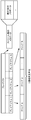
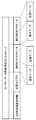
- FIG. 1 is a diagram for explaining the evolution of video technology.
- FIG. 2 is a diagram for explaining the relationship between the master, the distribution method, and the display device when HDR is introduced.
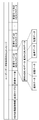
- FIG. 3 is an explanatory diagram of a method for determining the code value of the luminance signal stored in the content and the process of restoring the luminance value from the code value during reproduction.
- FIG. 4 is a diagram illustrating an example of HDR metadata.
- FIG. 5 is a diagram illustrating a storage example of static HDR metadata.
- FIG. 6 is a diagram illustrating a storage example of dynamic HDR metadata.
- FIG. 7 is a flowchart of a method for transmitting static HDR metadata.
- FIG. 8 is a flowchart of an HDR metadata processing method.
- FIG. 1 is a diagram for explaining the evolution of video technology.
- FIG. 2 is a diagram for explaining the relationship between the master, the distribution method, and the display device when HDR is introduced.
- FIG. 3 is an explanatory diagram
- FIG. 9 is a block diagram showing the configuration of the data output apparatus.
- FIG. 10 is a diagram illustrating an example of a data structure of an SEI message storing HDR metadata.
- FIG. 11 is a diagram illustrating an example of a data structure of an SEI message storing HDR metadata.
- FIG. 12 is a diagram illustrating an example of a data structure of an SEI message storing HDR metadata.
- FIG. 13 is a block diagram illustrating a configuration example of the data output device.
- FIG. 14 is a block diagram illustrating a configuration example of the DR conversion unit.
- FIG. 15 is a block diagram illustrating a configuration example of the DR conversion unit.
- FIG. 16 is a diagram illustrating an example of instruction contents of the HDR meta interpretation unit.
- FIG. 10 is a diagram illustrating an example of a data structure of an SEI message storing HDR metadata.
- FIG. 11 is a diagram illustrating an example of a data structure of an SEI message storing HDR metadata.
- FIG. 17 is a diagram illustrating an example of instruction contents of the HDR meta interpretation unit.
- FIG. 18 is a diagram illustrating an example of the instruction content of the HDR meta interpretation unit.
- FIG. 19 is a block diagram illustrating a configuration example of the data output device.
- FIG. 20 is a diagram illustrating a combination example of the characteristics of the video signal and the display device and the output signal of the data output device.
- FIG. 21 is a diagram illustrating an example of an operation model when various signals are reproduced and signals are output to various TVs.
- FIG. 22 is a diagram illustrating an example of a user guidance display method.
- FIG. 23 is a diagram illustrating an example of a user guidance display method.
- FIG. 24 is a diagram illustrating an example of a user guidance display method.
- FIG. 25 is a diagram illustrating an example of a user guidance display method.
- FIG. 26 is a diagram for explaining the reproduction operation of the dual disc.
- FIG. 27 is a flowchart showing a dual disk playback operation.
- FIG. 28 is a diagram showing the types of BDs.
- FIG. 29 is a diagram showing the types of BDs in more detail.
- FIG. 30 is a first diagram showing the data capacity recorded on the BD.
- FIG. 31 is a second diagram showing the data capacity recorded on the BD.
- FIG. 32 is a diagram illustrating an example of a combination of a video stream and a graphic stream recorded on each of a BD and a dual stream disc.
- FIG. 33 is a diagram showing another example of a combination of a video stream and a graphic stream recorded on each of a BD disc and a dual stream disc.
- FIG. 34 is a diagram showing still another example of a combination of a video stream and a graphic stream recorded on each of a BD disc and a dual stream disc.
- FIG. 35A is a diagram illustrating an example of a display process in which HDR display is performed by converting an HDR signal in HDRTV.
- FIG. 35B is a diagram illustrating an example of a display process for performing HDR display using an HDR-compatible playback device and SDRTV.
- FIG. 35C is a diagram illustrating an example of a display process for performing HDR display on an HDR-compatible playback device and SDRTV that are connected to each other via a standard interface.
- FIG. 36 is a diagram for describing a conversion process from HDR to pseudo-HDR.
- FIG. 37A is a diagram illustrating an example of EOTF (Electro-Optical Transfer Function) corresponding to each of HDR and SDR.
- FIG. 37B is a diagram illustrating an example of inverse EOTF corresponding to each of HDR and SDR.
- FIG. 38 is a block diagram illustrating configurations of the conversion device and the display device according to the embodiment.
- FIG. 39 is a flowchart illustrating a conversion method and a display method performed by the conversion device and the display device according to the embodiment.
- FIG. 40A is a diagram for describing the first luminance conversion.
- FIG. 40B is a diagram for describing another example of the first luminance conversion.
- FIG. 41 is a diagram for describing the second luminance conversion.
- FIG. 42 is a diagram for describing the third luminance conversion.
- FIG. 43 is a flowchart showing detailed display setting processing.
- a data output device is a data output device, and includes a decoding unit that generates a first video signal by decoding a video stream, and at least one first that converts a luminance range of the video signal.
- An acquisition unit that acquires one or more metadata corresponding to the conversion mode, characteristic data indicating a luminance range of the first video signal by interpreting one of the one or more metadata, and the first video
- a conversion auxiliary data for converting the luminance range of the signal
- a control information generating unit that converts the characteristic data into control information according to a predetermined transmission protocol
- a luminance range of the video signal includes a decoding unit that generates a first video signal by decoding a video stream, and at least one first that converts a luminance range of the video signal.
- Serial comprises a conversion unit for generating a second video signal of a narrow luminance range than the luminance range of the first video signal, and an output unit which outputs the second image signal and the control information to the display device in the transmission protocol.
- the data output device can change the luminance range of the video signal based on one or more metadata, and can output the converted video signal and control information.
- the interpretation unit further includes one or more first conversion modes for converting a luminance range of a video signal, which corresponds to the one or more first conversion modes, the one or more second conversion modes, and the display device. Based on the three conversion modes, it may be determined which of the data output device and the display device performs the conversion process.
- the data output device includes a first conversion mode corresponding to one or more metadata, a second conversion mode corresponding to the data output device, and a third conversion mode corresponding to the display device. Based on the above, it is possible to determine which of the data output device and the display device performs the conversion process. Thereby, the data output apparatus can determine the apparatus which performs an appropriate conversion process.
- the conversion unit corresponds to a plurality of second conversion modes including the one or more second conversion modes, each corresponding to each of the plurality of second conversion modes, and a corresponding second conversion mode.
- a plurality of mode processing units that perform the above process may be provided.
- the conversion unit includes a basic processing unit that performs a common process in the one or more second conversion modes, and each of the conversion units corresponds to each of the one or more second conversion modes. And one or more extended mode processing units.
- the interpretation unit further determines a conversion mode included in the one or more first conversion modes and included in the one or more second conversion modes as a conversion mode of conversion processing performed by the data output device. May be.
- the data output device can determine the conversion mode to be used based on the first conversion mode corresponding to one or more metadata and the second conversion mode supported by the data output device.
- the interpretation unit further includes a conversion mode included in the one or more first conversion modes and included in at least one of the one or more second conversion modes and the third conversion mode. You may determine to the conversion mode of the conversion process performed with the said display apparatus.
- the data output device includes a first conversion mode corresponding to one or more metadata, a second conversion mode corresponding to the data output device, and a third conversion mode corresponding to the display device. Based on the above, the conversion mode to be used can be determined.
- the acquisition unit acquires a plurality of metadata corresponding to a plurality of first conversion modes including the one or more first conversion modes, and the conversion unit includes a plurality of metadata including the one or more second conversion modes.
- the conversion mode having the highest reproducibility with respect to the master image that is an image output without converting the luminance range may be determined as the conversion mode of the conversion process performed by the data output device or the display device.
- the data output device can select the conversion mode with the highest reproducibility for the master image, the image quality of the displayed video can be improved.
- the interpretation unit performs the conversion process in the data output device. You may decide to do it.
- the interpretation unit performs the conversion process on the display device when the determined conversion mode of the conversion process is included in the third conversion mode and not included in the second conversion mode. May be determined.
- the interpretation unit further performs the conversion process performed by the data output device or the display device depending on whether or not the parameters for each of the plurality of first conversion modes can be acquired from the display device.
- the conversion mode may be determined.
- the data output device determines the conversion mode to be used according to whether or not the parameter of the display device can be acquired, a more appropriate conversion mode can be selected.
- the interpretation unit is included in the plurality of first conversion modes, is included in at least one of the plurality of second conversion modes and the third conversion mode, and can acquire the parameters from the display device.
- the conversion mode may be determined as a conversion mode of conversion processing performed by the data output device or the display device.
- the parameter may indicate a maximum value of a luminance range that can be displayed by the display device or a display mode in which the display device can display.
- the data output device further includes a down-conversion unit that generates a third video signal by lowering the resolution of the first video signal, and the output unit further outputs the third video signal to the display device. May be output.
- the data output device can change the resolution of the video signal to a resolution suitable for, for example, a display device.
- the conversion unit further performs the conversion process of the luminance range of the third video signal according to any one of the one or more second conversion modes based on the auxiliary conversion data, thereby the third video signal.
- a fourth video signal having a luminance range narrower than the luminance range may be generated, and the output unit may further output the fourth video signal to the display device.
- the data output device can change the resolution and luminance range of the video signal to a resolution and luminance range suitable for, for example, a display device.
- the display device does not support the display of the video having the resolution of the first video signal
- the down-conversion unit generates the third video signal
- the output unit is The third video signal may be output to the display device.
- the converter when the display device does not support the display of the video in the luminance range of the first video signal, (1) the converter generates the second video signal, and (2) the output unit The second video signal and the control information may be output to the display device.
- a data output method is a data output method in a data output device, and includes a decoding step of generating a first video signal by decoding a video stream, and converting a luminance range of the video signal
- a conversion auxiliary data for converting a luminance range of the first video signal
- a control information generation step for converting the characteristic data into control information according to a predetermined transmission protocol
- the conversion unit corresponding to one or more second conversion modes for converting the luminance range of the video signal uses any one of the one or more second conversion modes based on the conversion auxiliary data.
- a conversion step of generating a second video signal having a luminance range narrower than the luminance range of the first video signal by performing a conversion process of the luminance range of the first video signal, the second video signal, and the control Outputting information to the display device using the transmission protocol.
- the data output method includes a first conversion mode corresponding to a plurality of metadata, a second conversion mode corresponding to the data output device, and a third conversion mode corresponding to the display device. Based on the above, it is possible to determine which of the data output device and the display device performs the conversion process. Thereby, the data output method can determine the apparatus which performs an appropriate conversion process.
- a program according to an aspect of the present disclosure causes a computer to execute the data output method.
- a data generation method is a data generation method performed by a data generation device, and generates one or more metadata corresponding to one or more conversion modes for converting a luminance range of a video signal.
- the data generation method can generate a video stream including metadata corresponding to one or more conversion modes.
- an appropriate conversion mode can be selected in a playback device or the like that plays back the video stream.
- a configuration example 2 of the data output apparatus] will be described.
- each of the embodiments described below shows a specific example of the present disclosure.
- constituent elements that are not described in the independent claims indicating the highest concept are described as optional constituent elements.
- An HDR (High Dynamic Range) signal which is an image signal having a luminance range higher than that of a conventional image signal, is a package media such as a Blu-ray (registered trademark, hereinafter the same) disc storing the HDR signal, broadcast, or OTT (Over Thee). It is distributed via a distribution medium such as (Top).
- OTT means a Web site provided on the Internet, content or service such as video or audio, or a provider that provides them.
- the distributed HDR signal is decoded by a Blu-ray device or the like.
- the decoded HDR signal is sent to an HDR compatible display device (TV, projector, tablet, smartphone, etc.), and an HDR video is reproduced by the HDR compatible display device.
- the HDR technology is still at an early stage, and it is assumed that a new HDR method will be developed after the introduction of the first introduced HDR technology.
- the new HDR method can be adopted by storing the HDR signal (and metadata) of the newly created HDR method in the HDR distribution medium.
- the original technology can be used without changing a decoding device (for example, a Blu-ray device) designed for the original distribution medium.
- a decoding device for example, a Blu-ray device
- FIG. 1 is a diagram for explaining the evolution of video technology.
- SD Standard Definition
- HD high definition 1920 x 1080 pixels
- the dynamic range is the maximum brightness to express bright light such as specular reflection light that cannot be expressed by the current TV signal with more realistic brightness while maintaining the dark gradation in the conventional video.
- HDR High Dynamic Range
- SDR Standard Dynamic Range
- the maximum luminance value was 100 nits, whereas in HDR the maximum is 1000 nits or more. It is assumed that the luminance value is enlarged. Standardization of HDR is underway in SMPTE (Society of Motion Picture & Television Engineers) and ITU-R (International Telecommunications Union Radiocommunications Sector).
- HDR high definition video recorder
- package media Blu-ray Disc, etc.
- Internet distribution etc., like HD and UHD.
- the luminance of the video is composed of luminance values in the HDR luminance range, and a luminance signal obtained by quantizing the luminance value of the video is referred to as an HDR signal.
- the luminance of the video is composed of luminance values in the luminance range of SDR, and a luminance signal obtained by quantizing the luminance value of the video is called an SDR signal.
- FIG. 2 is a diagram showing a relationship between a flow for producing a master for home entertainment of SDR and HDR, a distribution medium, and a display device.
- the HDR concept has been proposed and its effectiveness at the HDR concept level has been confirmed.
- the first implementation method of HDR is proposed.
- a large amount of HDR content was created using this method, and the first implementation method was not verified. For this reason, when the production of HDR content becomes full-scale in the future, there is a possibility that the current HDR production method, particularly metadata, will change.
- FIG. 3 is an explanatory diagram of a method for determining the code value of the luminance signal stored in the content and the process of restoring the luminance value from the code value during reproduction.
- the luminance signal indicating the luminance in this example is an HDR signal corresponding to HDR.
- the image after grading is quantized by the inverse EOTF of HDR, and the code value corresponding to the luminance value of the image is determined. Image coding or the like is performed based on this code value, and a video stream is generated. At the time of reproduction, the decoding result of the stream is converted into a linear signal by inverse quantization based on HDR EOTF, and the luminance value for each pixel is restored.
- quantization using the inverse EOTF of HDR is referred to as “inverse HDR EOTF conversion”.
- Inverse quantization using HDR EOTF is referred to as “HDR EOTF conversion”.
- quantization using inverse SDR EOTF is referred to as “inverse SDR EOTF conversion”.
- Inverse quantization using SDR EOTF is referred to as “SDR EOTF conversion”.
- the HDR image can be displayed on the video display unit by converting the luminance value and metadata into a luminance value that can be displayed on the video display unit by the video conversion processing unit. For example, when the peak brightness of the original HDR video is 2000 nits and the peak brightness of the video display unit is 800 nits, conversion can be performed to lower the brightness.
- the HDR master method is realized by a combination of EOTF, metadata, and HDR signal. Therefore, more efficient EOTF and metadata may be developed, and it may be time to adopt the HDR method using such EOTF and metadata.
- This disclosure aims to promote the spread of HDR by reducing the risk that a customer who bought an HDR-compatible device re-buys a new device even when the HDR transmission format is changed in this way.
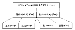
- FIG. 4 is a diagram illustrating an example of HDR metadata.
- the HDR metadata includes conversion auxiliary information used for changing the luminance range of the video signal (DR conversion) and HDR control information.
- Each piece of information is either static HDR metadata provided in units of titles or dynamic HDR metadata provided in units of frames, for example.
- static HDR metadata is classified as either essential metadata (basic data) or selection metadata (extended data), and dynamic HDR metadata is classified as selection metadata. Details of each information will be described later.
- HDR metadata As parameters indicating characteristics at the time of mastering in HDR content, there are static HDR metadata that is fixed for each title or each playlist and dynamic HDR metadata that is variable for each scene.
- the title and the playlist are information indicating video signals that are continuously reproduced.
- video signals that are continuously played back are referred to as continuous playback units.
- static HDR metadata includes at least one of EOTF function (curve) type, 18% Gray value, Diffuse White value, Knee point, and Clip point.
- the EOTF is information that associates a plurality of luminance values with a plurality of code values, and is information for changing the luminance range of the video signal. Since the other information is attribute information regarding the luminance of the video signal, the static HDR metadata is information regarding the luminance range of the video signal and can be said to be information for specifying the luminance range of the video signal.
- the 18% Gray value and the Diffuse White value indicate the luminance value (nit) in a video with a predetermined reference brightness, in other words, the reference brightness in the video. More specifically, the 18% Gray value indicates a luminance value (nit) after mastering of an object having a brightness of 18 nits before mastering.
- the Diffuse White value indicates a luminance value (nit) corresponding to white.
- Knee point and Clip point are parameters of the EOTF function and indicate the point at which the characteristics of EOTF change. Specifically, Knee point differs from the one-to-one increment in the luminance value (output luminance) mapped to the EOTF as the luminance of the video signal with respect to the original luminance value (input luminance) at the time of shooting. Indicates the change point to be a value. For example, Knee point is information for specifying a point that deviates from a linear change in FIG. 30A described later.
- Clip point indicates the point at which clipping starts in the EOTF function.
- clip refers to converting an input luminance value greater than a certain value into the same output luminance value. For example, Clip point indicates a point where the output luminance value does not change in FIG. 30B described later.
- EOTF functions are, for example, HDR EOTF and SDR EOTF shown in FIG. 27A.
- the content data generation method is a content data generation method for generating content data, in which a video signal and a plurality of images (continuous playback units are included in the continuous playback unit of the video signal)
- the information regarding the luminance range of the video signal is information for converting the luminance range of the video signal.
- the static HDR metadata includes information for specifying an EOTF that associates a plurality of luminance values with a plurality of code values.
- the luminance value in the video signal is encoded as a code value.
- the static HDR metadata further includes information indicating a luminance value in a video signal having a predetermined reference brightness, or information indicating a point at which a characteristic in EOTF changes.
- the static HDR metadata includes information (Diffuse White value) indicating a luminance value corresponding to white in the video signal.
- dynamic HDR metadata (second metadata) that is information that is commonly used for a unit smaller than the continuous reproduction unit and that is information on the luminance range of the video signal is further generated.
- the information regarding the luminance range of the video signal is information for converting the luminance range of the video signal.
- the dynamic HDR metadata is a parameter indicating a mastering characteristic that is different for each scene.
- the mastering characteristic indicates the relationship between the original luminance (before mastering) and the luminance after mastering.
- the parameter indicating the mastering characteristic is the same information as the static HDR metadata described above, in other words, is at least one piece of information included in the static HDR metadata.
- FIG. 5 is a diagram showing a storage example of static HDR metadata.
- static HDR metadata is stored in a playlist in a package medium such as a Blu-ray disc.
- Static HDR metadata is stored as one piece of metadata for each stream referenced from the playlist.
- static HDR metadata is fixed for each playlist. That is, the static HDR metadata is stored in association with each playlist.
- static HDR metadata may be stored in a manifest file that is referred to prior to stream acquisition. That is, the content data generation method according to the present embodiment may generate a video signal as a video stream, and store static HDR metadata in a manifest file that is referenced prior to acquisition of the video stream.
- static HDR metadata may be stored in a descriptor indicating the attribute of a stream. That is, the content data generation method according to the present embodiment may generate content data as a video stream, and store static HDR metadata as an identifier indicating the attribute of the video stream independently of the video stream.
- static HDR metadata can be stored as a descriptor (descriptor) in MPEG2-TS.
- the static HDR metadata when the static HDR metadata is fixed for each title, the static HDR metadata may be stored as management information indicating title attributes.
- FIG. 6 is a diagram illustrating an example of storing dynamic HDR metadata in a video stream.
- MPEG-4 AVC or HEVC High Efficiency Video Coding
- information related to stream reproduction control is stored using a data structure called SEI (Supplemental Enhancement Information).
- SEI Supplemental Enhancement Information
- dynamic HDR metadata is stored in SEI.
- the head of the scene is a head access unit (AU) of a random access unit such as GOP (Group Of Pictures). Therefore, the dynamic HDR metadata may be stored in the head access unit in the decoding order in the random access unit.
- the head access unit of the random access unit is an IDR picture or a non-IDR I picture to which SPS (Sequence Parameter Set) is added. Therefore, the receiving-side apparatus can acquire dynamic HDR metadata by detecting a NAL (Network Abstraction Layer) unit that constitutes a first access unit in a random access unit.
- NAL Network Abstraction Layer
- SEI that stores dynamic HDR metadata.
- the type of the EOTF function may be stored as stream attribute information in the SPS. That is, in the content data generation method according to the present embodiment, content data may be generated as a video stream encoded by HEVC, and information for specifying EOTF may be stored in an SPS included in the video stream.
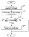
- FIG. 7 is a diagram illustrating a transmission method of static HDR metadata.
- a playback device such as a BD player (Blu-ray device) or a recorder
- the display device transmits the static HDR metadata to the display device through a transmission protocol such as HDMI (registered trademark, the same applies hereinafter).
- HDMI registered trademark, the same applies hereinafter
- the playback device acquires the static HDR metadata from the content management information at the start of playback of the title or playlist.
- Static HDR metadata is stored and transmitted as HDMI control information.
- the playback device acquires static HDR metadata corresponding to the title or playlist prior to the start of transmission of the video signal constituting the title or playlist, and controls the acquired static HDR metadata according to HDMI. It transmits as information (S402). More generally, the playback device may transmit static HDR metadata as initialization information when performing an HDMI initialization process between the playback device and the display device.
- the playback device transmits a video stream corresponding to the static HDR metadata (S403). Note that the transmitted static HDR metadata is valid for this video stream.
- the video stream transmission method is a video stream transmission method for transmitting a video stream (video stream), and is common to a video signal and a plurality of images included in a continuous reproduction unit.
- content data including static HDR metadata (first metadata) relating to a luminance range of a video signal, a video stream corresponding to the video signal, and a static HDR meta A transmission step of transmitting data.
- the video stream and static HDR metadata are transmitted according to the HDMI communication protocol.
- dynamic HDR metadata is transmitted as part of the video stream.
- the playback apparatus may transmit the dynamic HDR metadata as an HDMI control signal at a timing when the dynamic HDR metadata becomes valid.
- the playback device transmits the static HDR metadata and the dynamic HDR metadata so that they can be distinguished from each other by providing an identifier or the like.
- only the data structure of the container for storing the dynamic HDR metadata may be defined so that the contents of the SEI can be copied as it is as the payload data of the container.
- the reproduction device can be changed even if the syntax of the static HDR metadata is changed. It can be handled without changing the implementation. That is, the container data structure for storing the static HDR metadata is defined. In the transmission step, the static HDR metadata included in the content data is copied to the payload of the container, and the container is transmitted. May be.
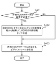
- FIG. 8 is a flowchart illustrating an example of a method for processing HDR metadata when an HDR signal is displayed on the display device.
- the display device acquires static HDR metadata from the HDMI control information (S411), and determines a display method of the HDR signal based on the acquired static HDR metadata (S412).
- the display device determines an HDR signal display method based on a value predetermined in the application standard or a default setting of the display device. . That is, in the video display method according to the present embodiment, when static HDR metadata cannot be acquired, the video display method corresponding to the video signal is determined based on a predetermined value or setting.
- the display device updates the HDR signal display method based on the dynamic HDR metadata (S414). That is, in the video display method according to the present embodiment, when static HDR metadata is acquired, the display method is determined based on the acquired static HDR metadata, the video is displayed, and dynamic HDR metadata is acquired. In such a case, the display method determined based on the static HDR metadata is updated to the display method determined based on the dynamic HDR metadata, and the video is displayed. Alternatively, the display method may be determined based on both static HDR metadata and dynamic HDR metadata.
- the display device may operate based only on static HDR metadata. Even when the display device supports the acquisition of dynamic HDR metadata, the display device displays the HDR signal in synchronization with the display time (PTS: Presentation Time Stamp) of the access unit storing the metadata. The method may not be updated. In this case, the display device may update the display method from the access unit displayed after the earliest time at which the display method can be updated after obtaining the metadata.
- PTS Presentation Time Stamp
- each of the static HDR metadata and the dynamic HDR metadata may include a plurality of versions, and may include a basic unit that is used in common by a plurality of versions and an extension unit that is different for each version. By doing so, backward compatibility in the display device can be ensured based on the HDR metadata of the basic part.
- the video display method according to the present embodiment is a video display method for displaying video based on the video stream, and the video stream corresponding to the video signal and the static HDR metadata (first metadata). And a display step of determining and displaying a video display method corresponding to the video signal based on the static HDR metadata.
- the luminance value in the video signal is encoded as a code value
- the static HDR metadata includes information for specifying an EOTF that associates a plurality of luminance values with a plurality of code values, and is displayed.
- a video is generated by converting a code value indicated by the video signal into a luminance value using EOTF specified by the static HDR metadata.
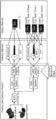
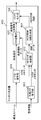
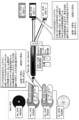
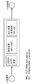
- FIG. 9 is a block diagram showing a configuration of a data output device 400 that outputs an HDR signal such as a BD player.
- the HDR metadata input to the data output device 400 indicates characteristic data indicating the mastering characteristic of the HDR signal and a tone mapping method when converting the HDR signal into the SDR signal or converting the dynamic range of the HDR signal. Conversion auxiliary data.
- These two types of metadata are stored as static HDR metadata or dynamic HDR metadata, as described with reference to FIGS.
- the static HDR metadata is stored in at least one of the content management information and the video stream.
- the data output device 400 includes a video decoding unit 401, an external meta acquisition unit 402, an HDR meta interpretation unit 403, an HDR control information generation unit 404, a DR conversion unit 405, and an HDMI output unit 406.
- the video decoding unit 401 generates a video signal (first video signal) by decoding a video stream that is an encoded video stream, and outputs the obtained video signal to the DR conversion unit 405.
- the video decoding unit 401 acquires HDR metadata (second metadata) (static HDR metadata or dynamic HDR metadata) in the video stream.
- the video decoding unit 401 outputs the HDR metadata stored in an MPEG-4 AVC or HEVC SEI message to the HDR meta interpretation unit 403.
- the external metadata acquisition unit 402 acquires static HDR metadata (first metadata) stored in content management information such as a playlist, and outputs the acquired static HDR metadata to the HDR meta interpretation unit 403. .
- static HDR metadata first metadata
- dynamic HDR metadata that can be changed in a predetermined unit that can be randomly accessed, such as a play item, may be stored in the content management information.
- the external meta acquisition unit 402 acquires dynamic HDR metadata from content management information, and outputs the acquired dynamic HDR metadata to the HDR meta interpretation unit 403.
- the HDR meta interpretation unit 403 determines the type of HDR metadata output from the video decoding unit 401 or the external meta acquisition unit 402, outputs the characteristic data to the HDR control information generation unit 404, and converts the conversion auxiliary data into the DR conversion unit. Output to 405.
- the HDR meta interpretation unit 403 obtains the characteristic data and the conversion auxiliary data by analyzing the first metadata when the first metadata and the second metadata are obtained together. To do.
- the HDR meta interpretation unit 403 uses the static HDR metadata as valid metadata when the external metadata acquisition unit 402 acquires the static HDR metadata, and the video decoding unit 401 further uses the static HDR metadata.
- valid metadata may be overwritten with the static HDR metadata. That is, the first metadata acquired by the external metadata acquisition unit 402 and the second metadata acquired by the video decoding unit 401 are commonly used for a plurality of images included in the continuous playback unit of the first video signal.
- the HDR meta interpretation unit 403 analyzes the first metadata when only the first metadata is acquired from the first metadata and the second metadata. When the data and the conversion auxiliary data are acquired and the second metadata is acquired, the metadata to be used is switched from the first metadata to the second metadata.
- the HDR control information generation unit 404 generates HDR control information in HDMI based on the characteristic data, and outputs the generated HDR control information to the HDMI output unit 406.
- the output timing of the HDR control information in the HDMI output unit 406 is determined so that the HDR control information can be output in synchronization with the video signal for which the metadata is valid. That is, the HDMI output unit 406 outputs the HDR control information in synchronization with a video signal (video signal) for which metadata becomes valid.
- the DR conversion unit 405 converts the decoded video signal into an SDR signal or converts the dynamic range based on the conversion auxiliary data.
- the data output device 400 can determine whether conversion processing is necessary by confirming whether the connected display device supports the input of an HDR signal in an HDMI initialization process or the like. Good.
- the first video signal obtained by the video decoding unit 401 is input to the HDMI output unit 406 without passing through the DR conversion unit 405.
- the HDMI output unit 406 displays the first video signal and the HDR control information when the display device connected to the data output device 400 supports video output in the luminance range of the HDR signal (first video signal). Output to the display device. Also, the HDMI output unit 406 displays the second video obtained by converting HDR into SDR when the display device connected to the data output device 400 does not support video output in the luminance range of the HDR signal (first video signal). The signal and the HDR control information are output to the display device. Also, the HDMI output unit 406 determines whether or not the display device supports video output in the luminance range of the HDR signal (first video signal) in the initialization process of the transmission protocol (for example, HDMI).
- the transmission protocol for example, HDMI
- the HDMI output unit 406 outputs the video signal output from the DR conversion unit 405 or the video decoding unit 401 and the HDR control information according to the HDMI protocol.
- the same configuration can be used when the data output device 400 receives and outputs broadcast or OTT content. Further, when the data output device 400 and the display device are included in a single device, the HDMI output unit 406 is not necessary.
- the data output device 400 includes the external metadata acquisition unit 402 that acquires metadata from management information and the like, and the video decoding unit 401 has a function of acquiring metadata from a video stream.
- the output device 400 may have only one of them.
- the data output device 400 outputs data (video signal and HDR control information) according to HDMI has been described. However, if the data output device 400 outputs data according to an arbitrary transmission protocol, Good.
- the data output device 400 relates to the decoding unit (video decoding unit 401) that generates the first video signal in the first luminance range (HDR) by decoding the video stream, and the luminance range of the first video signal.
- the acquisition unit at least one of the video decoding unit 401 and the external metadata acquisition unit 402 and interpreting the first metadata acquire characteristic data indicating the luminance range of the first video signal.
- An interpretation unit HDR meta-interpretation unit 403
- a control information generation unit HDR control information generation unit 404 that converts characteristic data into HDR control information according to a predetermined transmission protocol (for example, HDMI), and HDR control information
- an output unit (HDMI output unit 406) that outputs a predetermined transmission protocol.
- the data output device 400 can generate control information based on the characteristic data included in the metadata.
- the interpretation unit (HDR meta-interpretation unit 403) further obtains conversion auxiliary data for converting the luminance range of the first video signal by interpreting the first metadata
- the data output device 400 Furthermore, a conversion unit (DR conversion unit 405) is provided that generates a second video signal having a luminance range narrower than the luminance range of the first video signal by converting the luminance range of the first video signal based on the auxiliary conversion data.
- the output unit (HDMI output unit 406) further outputs at least one of the first video signal and the second video signal using a predetermined transmission protocol.
- the data output device 400 can change the luminance range of the first video signal by using the conversion auxiliary data included in the metadata.
- the decoding unit (video decoding unit 401) further acquires second metadata (HDR metadata) related to the luminance range of the first video signal from the video stream, and the interpretation unit (HDR meta-interpretation unit 403)
- the characteristic data and the conversion auxiliary data are acquired by analyzing at least one of the first metadata and the second metadata.
- static HDR metadata includes essential metadata and selection metadata
- dynamic HDR metadata includes only selection metadata. That is, static HDR metadata is always used, and dynamic HDR metadata is selectively used.
- the first metadata acquired by the external meta acquisition unit 402 or the second metadata acquired by the video decoding unit 401 is used in common for a plurality of images included in the continuous reproduction unit of the video signal.
- static HDR metadata static metadata
- the HDR control information generation unit 404 converts the characteristic data included in the static HDR metadata into HDR control information according to a predetermined transmission protocol.
- the HDMI output unit 406 outputs HDR control information based on static HDR metadata.
- the first metadata acquired by the external metadata acquisition unit 402 or the second metadata acquired by the video decoding unit 401 is further commonly used for a unit smaller than the continuous reproduction unit of the video signal, and has characteristics.
- Dynamic HDR metadata including data (dynamic metadata) is included.
- the HDR control information generation unit 404 converts the characteristic data included in the static HDR metadata and the specific data included in the dynamic HDR metadata into HDR control information according to a predetermined transmission protocol.
- the HDMI output unit 406 outputs HDR control information based on static HDR metadata and dynamic HDR metadata.
- a data generation method is a data generation method performed by a data generation device, and includes a first generation step of generating metadata related to a luminance range of a video signal, and a video stream including the video signal and metadata.
- a second generation step of generating The metadata includes characteristic data indicating the luminance range of the video signal and conversion auxiliary data for converting the luminance range of the video signal.
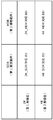
- FIG. 10 is a diagram illustrating an example of a data structure of an SEI message storing HDR metadata.
- a dedicated SEI message for HDR metadata may be defined. That is, the metadata may be stored in a message dedicated to metadata.
- HDR metadata is stored in a general-purpose SEI message for storing user data, and information (HDR extended identification information described later) indicating that HDR metadata is stored in the message in the payload portion of the message. It may be provided.
- the HDR metadata includes static HDR metadata and dynamic HDR metadata. Further, flag information indicating whether static HDR metadata is stored and flag information indicating whether dynamic HDR metadata is stored may be provided.
- there are three types of storage a method of storing only static HDR metadata, a method of storing only dynamic HDR metadata, and a method of storing both static HDR metadata and dynamic HDR metadata. The method can be used.
- basic data (basic part) that must be interpreted and extended data (extended part) that is optional (interpretation is optional)
- type information indicating the type of metadata (basic data or extension data) and a size are included in the header information, and a container format in which the metadata is stored in the payload is defined. That is, the metadata includes a payload, information indicating whether the payload data is basic data or extension data, and information indicating the payload data size.
- the metadata includes type information indicating the type of metadata. For example, basic data is stored in a container whose type value is 0. Further, one or more values are assigned as type values to the extension data, and the type of extension data is indicated by the value.
- the data output device and the display device refer to the type value and acquire container data that can be interpreted by the data output device and the display device.
- the data output device uses the type information to determine whether the data output device (or display device) can interpret the metadata, and the data output device (or display device) determines the metadata. If the data can be interpreted, the characteristic data and the conversion auxiliary data are acquired by interpreting the metadata.
- the maximum size of the HDR metadata may be set in advance, and the metadata may be generated so that the sum of the sizes of the basic data and the extended data is not more than the maximum size. That is, the maximum value of the metadata data size is defined, and the data generation method according to the present disclosure generates the metadata so that the total data size of the basic data and the extended data is equal to or less than the maximum value.
- the HDR data can be stored in the memory by providing the data for the maximum size in the data output device and the display device.
- Such a data structure may be used for storing HDR metadata in content management information.
- FIG. 11 is a diagram illustrating an example of a data structure when HDR metadata is stored in an SEI message for storing user data.
- the data structure is the same as that of FIG. 11 except that the message includes the HDR extension identification information and the extension type ID.
- the HDR extended identification information indicates that the message includes HDR metadata.
- the extension type ID indicates the HDR metadata version and the like. That is, the metadata is stored in the HEVC SEI message, and the SEI message includes HDR extended identification information indicating whether the SEI message includes metadata.
- the data output device receives the SEI message for storing user data including the HDR extended identification information, and the display device connected to the data output device supports the input of the HDR signal and the HDR control information.
- the received SEI message is copied and output as it is according to the protocol of the output I / F to the display device such as HDMI. That is, the data output device acquires an SEI message including HDR extended identification information indicating that the SEI message includes metadata, and the data output destination display device supports input of HDR control information.
- the SEI message is output as it is according to a predetermined transmission protocol (for example, HDMI).
- the data output device can output the HDR metadata to the display device regardless of the content of the metadata.
- a new DR conversion process is developed in the future, new HDR metadata is defined, and a display device corresponding to the new HDR metadata is connected to a data output device not corresponding to the new HDR metadata. Even in this case, the new HDR metadata can be output from the data output device to the display device.
- DR conversion processing according to the new HDR metadata can be performed in the display device.
- FIG. 12 is a diagram illustrating an example of a data structure when a plurality of HDR metadata is stored in one SEI message for storing user data.
- the SEI message stores a plurality of HDR metadata for a plurality of conversion modes (methods) related to dynamic range (brightness range) conversion.
- a field (number of conversion modes) indicating the number of conversion modes in which HDR metadata is provided is added to the data structure shown in FIG. Also, after the number of conversion modes, a plurality of HDR metadata corresponding to each conversion mode is stored in order.
- the data generation method is a data generation method performed by the data generation apparatus, and includes one or more metadata (HDR metadata) corresponding to one or more conversion modes for converting the luminance range of the video signal.
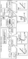
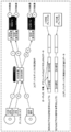
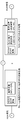
- FIG. 13 is a block diagram illustrating a configuration example of the data output device 500 according to the present embodiment.
- the data output device 500 includes a video decoding unit 501, an external meta acquisition unit 502, an HDR meta interpretation unit 503, an HDR control information generation unit 504, a DR conversion unit 505, and an HDMI output unit 506.
- the operations of the HDR meta interpretation unit 503 and the DR conversion unit 505 are different from those of the data output device 400 illustrated in FIG.
- the operations of the video decoding unit 501, the external meta acquisition unit 502, the HDR control information generation unit 504, and the HDMI output unit 506 are the video decoding unit 401, the external meta acquisition unit 402, the HDR control information generation unit 404, and the HDMI output unit 406. It is the same as the operation of.
- the data output device 500 is connected to the display device 510 (display unit), and outputs the generated video signal and HDR control information to the display device 510 via a predetermined transmission protocol such as HDMI.
- the DR conversion unit 505 and the display device 510 each correspond to a plurality of dynamic range conversion modes (conversion methods).
- “corresponding” means having a function of performing processing in the conversion mode.
- the HDR meta interpretation unit 503 acquires static HDR metadata and dynamic HDR metadata from the external meta acquisition unit 502 and the video decoding unit 501.
- a plurality of HDR metadata for a plurality of conversion modes is stored in the content management information or the encoded video stream.
- the HDR meta interpretation unit 503 determines a plurality of conversion modes corresponding to a plurality of HDR metadata as a plurality of usable conversion modes.
- the HDR meta interpretation unit 503 acquires information on the conversion mode of the HDR signal supported by the display device 510 by communicating with the display device 510 or via a separate network. Then, the HDR meta interpretation unit 503 (1) a conversion mode corresponding to the HDR metadata, (2) a conversion mode corresponding to the DR conversion unit 505, and (3) a conversion corresponding to the display device 510. Based on the mode, (1) which of the data output device 500 and the display device 510 performs the dynamic range conversion processing and (2) the conversion mode to be used is determined.
- the DR conversion unit 505 converts the HDR signal into an SDR signal according to the conversion mode instructed from the HDR meta interpretation unit 503.
- the data output device 500 transmits a video signal (HDR signal) to the display device 510, and converts the HDR metadata necessary for the conversion to an HDMI control signal ( (HDR control information) to the display device 510.
- the DR conversion unit 505 is compatible with a plurality of conversion modes, but may be compatible with one or more conversion modes.
- the data output device 500 may acquire one or more HDR metadata corresponding to one or more conversion modes.
- the data output device 500 has a decoding unit (video decoding unit 501) that generates the first video signal by decoding the video stream, and one or more first conversion modes that convert the luminance range of the video signal.
- the acquisition range at least one of the video decoding unit 501 and the external metadata acquisition unit 502 that acquires one or more corresponding metadata, and the luminance range of the first video signal by interpreting one of the one or more metadata Interpretation unit (HDR meta-interpretation unit 503) that obtains characteristic data indicating the above and conversion auxiliary data for converting the luminance range of the first video signal, and the characteristic data to a predetermined transmission protocol (for example, HDMI)
- HDR control information generation unit 504 for converting to the HDR control information according to the above, and one or more second conversion modes for converting the luminance range of the video signal, Based on the auxiliary conversion data, the second video signal having a luminance range narrower than the luminance range of the first video signal is obtained by performing the conversion process of the
- a conversion unit (DR conversion unit 505) to be generated and an output unit (HDMI output unit 506) that outputs the second video signal and the HDR control information to the display device 510 using a predetermined transmission protocol are provided.
- the interpretation unit (HDR meta-interpretation unit 503) further converts the luminance range of the video signal corresponding to the one or more first conversion modes, the one or more second conversion modes, and the display device 510. Based on the conversion mode, which of the data output device 500 and the display device 510 performs the conversion process is determined.
- the data output device 500 includes a first conversion mode corresponding to one or more metadata, a second conversion mode corresponding to the data output device 500, and a third conversion mode corresponding to the display device 510. Based on the conversion mode, it can be determined which of the data output device 500 and the display device 510 performs the conversion process. Thereby, the data output apparatus 500 can determine the apparatus which performs an appropriate conversion process.
- the one or more second conversion modes supported by the data output device 500 may include at least a part of a plurality of first conversion modes corresponding to one or more metadata, or one or more first conversion modes. None of the modes may be included.
- the third conversion mode supported by the display device 510 may include at least a part of the one or more first conversion modes, or may not include any of the one or more first conversion modes. Further, the third conversion mode may include at least a part of the one or more second conversion modes, or may not include any of the one or more second conversion modes.
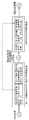
- FIG. 14 is a block diagram illustrating a configuration example of the DR conversion unit 505.
- the DR conversion unit 505 includes a mode determination unit 511, N mode processing units 512, and a conversion result output unit 513.
- Each of the N mode processing units 512 corresponds to each of the N conversion modes (processing methods), and performs processing of the corresponding conversion mode.
- the mode determination unit 511 acquires the conversion mode instructed from the HDR meta interpretation unit 503, and determines the mode processing unit 512 that performs the conversion process. That is, the mode determination unit 511 selects the mode processing unit 512 corresponding to the conversion mode instructed from the HDR meta interpretation unit 503.
- the determined mode processing unit 512 converts the HDR signal (video signal) into an SDR signal (video signal after conversion).
- the conversion result output unit 513 outputs the converted SDR signal.
- FIG. 15 is a block diagram illustrating a configuration example of a DR conversion unit 505A, which is another example of the DR conversion unit 505.
- the DR conversion unit 505 includes a mode determination unit 521, a basic processing unit 522, N extended mode processing units 523, and a conversion result output unit 524.
- the basic processing unit 522 performs a default conversion process that is a process common to the N conversion modes.
- the N extended mode processing units 523 perform extended processing such as dynamically controlling parameters of conversion processing using dynamic HDR metadata.
- the N extended mode processing units 523 each correspond to each of the N conversion modes, and perform an extended process of the corresponding conversion mode.
- the basic processing unit 522 operates using only static HDR metadata
- the extended mode processing unit 523 operates using dynamic HDR metadata in addition to static HDR metadata.
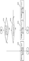
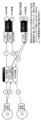
- HDR meta-interpretation unit 16 and 17 show instructions of the HDR meta interpreter 503 based on the conversion mode in which HDR metadata is provided, whether each mode is supported in the data output device 500, and whether each mode is supported in the display device 510. It is a figure which shows the example of the content.
- the HDR meta-interpretation unit 503 basically selects an operation with the highest reproducibility for the master image from among selectable combinations.
- the master image is an image output without changing the luminance range.
- the data output device 500 corresponds to mode 1 and mode 2, and the display device 510 does not support any conversion mode.
- mode 1 and mode 2 mode 2 is more reproducible with respect to the master image.
- the HDR meta interpretation unit 503 knows in advance the reproducibility of the master image in each mode. In this case, the HDR meta-interpretation unit 503 determines that the data output device 500 performs the conversion process, and selects the mode 2 with high reproducibility among the mode 1 and the mode 2.
- the data output device 500 corresponds to mode 1, and the display device 510 corresponds to mode 1 and mode 2.
- the HDR meta-interpretation unit 503 determines that the conversion process is to be performed by the display device 510 and selects mode 2 having high reproducibility among mode 1 and mode 2. Further, the data output device 500 outputs the HDR metadata corresponding to the conversion processing in mode 2 to the display device 510 as HDMI control information (HDR control information).
- the display device 510 performs a mode 2 conversion process using the control information.
- the HDR meta interpretation unit 503 is further included in one or more first conversion modes corresponding to one or more metadata, and included in one or more second conversion modes corresponding to the data output device 500.
- the conversion mode to be converted is determined as the conversion mode of the conversion process performed by the data output device 500.
- the HDR meta interpretation unit 503 further includes one or more second conversion modes included in one or more first conversion modes respectively corresponding to one or more metadata and corresponding to the data output device 500.
- the conversion mode included in at least one of the third conversion modes corresponding to the display device 510 is determined as the conversion mode of the conversion process performed by the data output device 500 or the display device 510.
- the HDR meta interpretation unit 503 includes the master image among the plurality of conversion modes included in the plurality of first conversion modes and included in at least one of the plurality of second conversion modes and the third conversion mode. Is determined as the conversion mode of the conversion process performed by the data output device 500 or the display device 510.
- the data output device 500 selects the conversion mode with the highest reproducibility among the conversion modes supported by the data output device 500 and the display device 510, and selects the mode selected from the data output device 500 and the display device 510. It is determined that conversion processing is performed by a compatible device.
- the HDR meta-interpretation unit 503 determines that the conversion mode of the determined conversion process is included in the second conversion mode and not included in the third conversion mode. It is determined that the data output device 500 performs the conversion process. Also, as shown in FIG. 17, the HDR meta-interpretation unit 503 causes the display device 510 to change the conversion mode of the determined conversion process to be included in the third conversion mode and not included in the second conversion mode. It is determined that the conversion process is performed.
- the data output device 500 is based on the first conversion mode corresponding to the plurality of metadata, the second conversion mode corresponding to the data output device, and the third conversion mode corresponding to the display device.
- the conversion mode to be used can be determined. Further, since the data output device 500 can select a conversion mode with the highest reproducibility for the master image, the image quality of the displayed video can be improved.
- FIG. 18 is a diagram illustrating an example in which the data output device 500 determines the conversion process depending on whether the parameter of the display device 510 can be acquired.
- the parameters of the display device 510 are the peak luminance of the display device 510 (the maximum value of the luminance range that can be displayed by the display device 510), the display mode in which the display device 510 can display, or the like. Specifically, this parameter indicates the currently viewing display mode as the display mode.
- the display mode includes a normal mode, a dynamic mode, a cinema mode, and the like.
- the data output device 500 corresponds to mode 1, mode 2, and mode 3, and the display device 510 corresponds to mode 1. Further, the data output device 500 can acquire the parameters of the display device 510 for the mode 1 and the mode 2, and cannot acquire the parameters of the display device 510 for the mode 3. Also, mode 2 has higher reproducibility than mode 1, and mode 3 has higher reproducibility than mode 2.
- the mode with the highest reproducibility among the modes supported by the data output device 500 and the display device 510 is the mode 3, but the data output device 500 cannot acquire the parameters of the display device 510 for the mode 3. Therefore, mode 3 is excluded. Then, the data output device 500 selects the conversion mode that uses the mode 2 that has the next highest reproducibility after the mode 3 and that can acquire parameters. Then, the data output device 500 acquires the parameters necessary for the mode 2 from the display device 510, and performs the conversion processing of the mode 2 using the acquired parameters.
- the HDR meta interpretation unit 503 further determines whether the parameters for each of the plurality of first conversion modes corresponding to the plurality of metadata can be acquired from the display device 510, depending on whether or not the data output device 500 can obtain the parameters.
- the conversion mode of the conversion process performed by the display device 510 is determined.
- the HDR meta interpretation unit 503 is included in the plurality of first conversion modes and is included in at least one of the plurality of second conversion modes and the third conversion mode, and acquires the parameters from the display device 510.
- the possible conversion mode is determined as the conversion mode of the conversion process performed by the data output device 500 or the display device 510.
- the data output device 500 selects the mode with the highest reproducibility among the conversion modes supported by the data output device 500 and the display device 510, and only the data output device 500 supports the selected mode. Then, it is determined whether or not the parameters of the display device 510 for the mode can be acquired. If the parameter can be acquired, the data output device 500 selects the mode. On the other hand, when the parameter cannot be acquired, the data output device 500 selects another mode (the mode with the next highest reproducibility).
- the data output device 500 determines the conversion mode to be used depending on whether or not the parameters of the display device 510 can be acquired, a more appropriate conversion mode can be selected.
- FIG. 19 is a block diagram showing the configuration of the data output device 500A.
- This data output device 500A further includes a DC unit 507 in addition to the data output device 500 shown in FIG.
- the DC unit 507 down-converts the resolution of the video signal obtained by the video decoding unit 501. For example, when the video signal is 4K, the DC unit 507 down-converts the 4K video signal into a 2K video signal.
- the data output device 500A (1) converts a 4K HDR signal into a 2K HDR signal and outputs it according to the resolution and dynamic range supported by the display device 510. (2) a 4K HDR signal Is converted to a 2K HDR signal and then output after changing the dynamic range in the DR conversion unit 505, and (3) a 4K SDR signal is converted into a 2K SDR signal and output, etc. Can be done. That is, the data output device 500A can switch the operation according to the resolution of the display device 510 and the presence / absence of HDR signal support.
- FIG. 20 is a diagram illustrating a combination example of the characteristics (resolution and dynamic range (luminance range)) of the video signal in the content, the characteristics of the display device 510, and the output signal of the data output device 500A.
- the data output device 500A selects the format of the output signal so as to match the resolution of the display device 510 and whether or not the HDR signal is supported, and the DC unit 507 and the DR conversion unit 505 so as to generate the output signal of the selected format. To control.
- the display device 510 does not support the display of an HDR signal with a resolution of 4K, and supports the display of an HDR signal with a resolution of 2K, data
- the output device 500A converts the video signal in the content into an HDR signal with a resolution of 2K and outputs it (see the combination example described in the second line in FIG. 20). At this time, the conversion of the resolution of the video signal is performed in the DC unit 507.
- the video signal in the content is an HDR signal with a resolution of 4K
- the display device 510 does not support the display of an HDR signal with a resolution of 4K and an HDR signal with a resolution of 2K, and also supports the display of an SDR signal of 2K.
- the data output device 500A converts the video signal in the content into an SDR signal with a resolution of 2K and outputs it (see the combination example described in the third row in FIG. 20). At this time, the conversion of the resolution of the video signal is performed by the DC unit 507, and the conversion of the luminance range is performed by the DR conversion unit 505.
- the display device 510 can reproduce the video signal of the content more faithfully.
- the data output device 500A may operate so that the display device 510 performs resolution conversion or dynamic range conversion as described in FIG.
- the data output device 500A includes the down-conversion unit (DC unit 507) that generates the third video signal by reducing the resolution of the first video signal obtained by the video decoding unit 501.
- the conversion unit (DR conversion unit 505) further converts the luminance range of the third video signal by performing conversion processing of the luminance range of the third video signal in any one of the plurality of second conversion modes based on the auxiliary conversion data.
- a fourth video signal having a luminance range narrower than the range is generated.
- the output unit (HDMI output unit 506) further outputs the third video signal or the fourth video signal to the display device 510.
- the data output device 500A can change the resolution of the video signal to a resolution suitable for the display device 510, for example.
- the down-conversion unit (DC unit 507) generates the third video signal and (2 )
- the output unit (HDMI output unit 506) outputs the third video signal to the display device 510.
- the resolution of the video signal is 4K and the resolution of the display device 510 is 2K, a 2K output signal is output.
- the conversion unit displays the luminance range (HDR) of the first video signal.
- a second video signal with a narrower luminance range (SDR) is generated.
- the output unit (HDMI output unit 506) outputs the second video signal and the HDR control information to the display device 510.
- the dynamic range (luminance range) of the video signal is HDR and the display device 510 does not support HDR (in the case of SDR)
- the HDR video signal is changed to the SDR video signal.
- the SDR video signal (output signal) is output after conversion.
- the down-conversion unit (DC unit 507) generates a third video signal
- the conversion unit (DR conversion unit 505) has a luminance range (SDR) narrower than the luminance range (HDR) of the third video signal.
- the output unit (HDMI output unit 506) outputs the fourth video signal to the display device 510.
- the resolution of the video signal is 4K
- the dynamic range (luminance range) of the video signal is HDR
- the resolution of the display device 510 is 2K
- the display device 510 supports HDR. If not (SDR), 2K and SDR output signals are output.
- FIG. 21 shows a 4K HDR signal, a 2K HDR signal, and a 4K SDR signal reproduced by a next-generation Blu-ray playback device, and the reproduced signals are converted to an HDR compatible 4KTV, an HDR non-compliant 4KTV, and It is a figure which shows the example of an operation
- the Blu-ray playback device acquires static HDR metadata stored in the content management information and dynamic HDR metadata stored in the encoded video stream.
- the Blu-ray playback device uses these HDR metadata to convert the video HDR signal into an SDR signal according to the characteristics of the output TV connected by HDMI, or outputs the HDR metadata. Are output as HDMI control signals.
- Each of the conversion process from the HDR signal to the SDR signal and the conversion process from the HDR signal to the video signal in the luminance range suitable for the display device can be selected and implemented from a plurality of methods.
- the HDR metadata corresponding to the implemented conversion process in the content management information or the video encoded stream at the time of content production, the effect of the conversion process can be enhanced.
- the content management information or the encoded stream can store a plurality of HDR metadata for each conversion method.
- the Blu-ray playback device may include a plurality of conversion processing units, such as an option conversion module B (option conversion module B) or an option conversion module D (option conversion module D) in the figure.
- a plurality of conversion processing units such as an option conversion module B (option conversion module B) or an option conversion module D (option conversion module D) in the figure.
- an HDR-compatible TV may include a plurality of conversion processing units, may include only one conversion processing unit, or may not include a conversion processing unit.
- HDR metadata is stored in a predetermined container in which an operation at the time of formatting or input is determined in advance.
- a display device corresponding to the new HDR metadata is connected to a Blu-ray playback device that does not support the new HDR metadata
- the new HDR metadata can be output from the Blu-ray playback device to the display device.
- conversion processing according to the new HDR metadata can be performed in the display device.
- the Blu-ray playback device corresponding to the new HDR metadata may perform the new conversion process on the video data in the playback device and output the processed video data to the display device. .
- the playback apparatus may down-convert a 4K signal into a 2K signal and output the signal according to the TV resolution.
- FIG. 22 is a diagram illustrating a user guidance display method on a Blu-ray device that executes HDR-to-SDR conversion processing.
- an HDR-compatible Blu-ray device connected to a non-HDR compatible TV detects the start of conversion processing from HDR to SDR, for example, “The disk is an HDR-compatible disk. Your TV is a non-HDR compatible TV. Therefore, a guide message such as “SDR video in which the Blu-ray device performs the conversion process from HDR to SDR is reproduced instead of the HDR video” is displayed.
- the data output device converts the first luminance range to the second luminance range when the display device does not support the video output of the luminance range of the first video signal (HDR signal).
- the second video signal (SDR signal) and the HDR control information are output to the display device, and the display device displays that the second video signal converted from the first luminance range to the second luminance range is displayed.
- FIG. 23 is a diagram showing a method for displaying user guidance when executing a conversion process from HDR to SDR stored in the disc.
- a message (menu) to be displayed by the Blu-ray device is stored in the HDR disk or a non-volatile memory in the Blu-ray device.
- the Blu-ray device can display a message when executing the conversion process from HDR to SDR.
- the disc is an HDR-compatible disc. Because your TV is non-HDR compatible, the Blu-ray device plays SDR video that has been converted from HDR to SDR instead of HDR video. Is displayed.
- FIG. 24 is a diagram showing a display method of the user guidance menu when executing the conversion process from HDR to SDR stored in the disc.
- the Blu-ray devices use the Blu-ray menu, “The disc is an HDR-compatible disc. Because your TV is non-HDR compatible, the Blu-ray device is not HDR video, and the Blu-ray device is from HDR to SDR. Message such as “Is it possible to play the SDR video that has been subjected to the conversion process” is displayed? The Blu-ray device starts displaying the converted image when the user selects the “Play” button. Also, if the user selects “do not play”, the Blu-ray device stops playing and displays a message prompting the user to insert a non-HDR compatible Blu-ray disc.
- the data output device converts the first luminance range to the second luminance range when the display device does not support the video output of the luminance range of the first video signal (HDR signal).
- a message for the user to select whether or not to display the second video signal (SDR signal) is displayed on the display device.
- FIG. 25 is a diagram showing a display method of a user guidance menu capable of selecting a processing method when executing a conversion process from HDR to SDR stored in the disc.
- the Blu-ray device displays this information when metadata for conversion processing from HDR to SDR is stored in Blu-ray.
- the Blu-ray device displays a message prompting that a more beautiful conversion is possible when the user selects a specified conversion method.
- the Blu-ray device says, “The disc is an HDR-compatible disc. Because your TV is non-HDR compatible, the Blu-ray device is not an HDR video, and the Blu-ray device has converted HDR to SDR.
- Display the selection menu of the HDR to SDR conversion processing method such as “Play back in process 1”, “Play back in process 3”, “Do not play back”. be able to.
- processing 1 and processing 3 are different conversion processing from HDR to SDR.
- the data output device converts the first luminance range to the second luminance range when the display device does not support the video output of the luminance range of the first video signal (HDR signal).
- the display device displays a message for the user to select one of a plurality of conversion methods.
- a similar message can be displayed in broadcasting.
- a TV or playback device that does not support HDR signals uses a data broadcast application or the like to display a message indicating that the broadcast program is an HDR signal and may not be displayed correctly when viewed with To do.
- the TV or the playback device that supports the HDR signal may not display the message.
- the tag value indicating the message attribute indicates that the message is a warning message for the HDR signal. The TV or playback device corresponding to the HDR signal determines that display of the message is unnecessary with reference to the tag value.
- FIG. 26 is a diagram for describing multiplexed data stored in a dual disk.
- the HDR signal and the SDR signal are stored as different multiplexed streams.
- data of a plurality of media such as video, audio, subtitles, and graphics is stored as one multiplexed stream by an MPEG-2 TS-based multiplexing method called M2TS.
- M2TS MPEG-2 TS-based multiplexing method
- These multiplexed streams are referred to from reproduction control metadata such as a playlist, and are reproduced by the player analyzing the metadata at the time of reproduction, or individual languages stored in the multiplexed stream. Select the data.
- playlists for HDR and SDR are individually stored, and each playlist refers to an HDR signal or an SDR signal. Further, identification information indicating that both the HDR signal and the SDR signal are stored may be separately indicated.
- HDR and SDR signals are multiplexed to satisfy a buffer model such as T-STD (System Target Decoder) defined in MPEG-2 TS.
- T-STD System Target Decoder
- Data such as audio, subtitles, or graphics needs to be stored for each multiplexed stream, and the amount of data increases compared to the case of multiplexing to one.
- the increase in the amount of data can reduce the amount of video data by using a video encoding method with a high compression rate.
- the compression ratio can be improved by 1.6 to 2 times.
- the dual disk is stored in a combination of 2K HDR and SDR, such as a combination of 4K SDR and 2K HDR, or 2K, or a combination of 2K and 4K. It is also possible to allow only combinations that fit within the capacity of the optical disk by prohibiting storing two.
- FIG. 27 is a flowchart showing a dual disk playback operation.
- the playback apparatus determines whether the playback target optical disk is a dual disk (S301). If it is determined that the disk is a dual disk (Yes in S301), it is determined whether the output TV is HDRTV or SDRTV (S302). If it is determined that it is HDRTV (Yes in S302), the process proceeds to step S303, and if it is determined that it is SDRTV (No in S302), the process proceeds to step S304. In step S303, an HDR video signal is acquired from the multiplexed stream including the HDR signal in the dual disc, decoded, and output to HDRTV.
- step S304 an SDR video signal is acquired from the multiplexed stream including the SDR signal in the dual disc, decoded, and output to SDRTV. If it is determined in step S301 that the playback target is not a dual disc (No in S301), whether or not playback is possible is determined by a predetermined method, and a playback method is determined based on the determination result (S305).
- FIG. 28 is a diagram showing the types of BDs.
- a BD on which a video signal having a resolution of the first resolution and a luminance range of the first luminance range is recorded as a 2K_SDR-compatible BD.
- a video signal whose resolution is the first resolution and whose luminance range is the first luminance range is stored as a stream on the BD. This stream is described as a 2K_SDR stream.
- the 2K_SDR compatible BD is a conventional BD.
- a BD on which a video signal having a resolution of the second resolution and a luminance range of the first luminance range is recorded as a 4K_SDR compatible BD.
- a video signal whose resolution is the second resolution and whose luminance range is the first luminance range is stored as a stream on the BD. This stream is described as a 4K_SDR stream.
- a BD on which a video signal having a resolution of the first resolution and a luminance range of the second luminance range is recorded as a 2K_HDR compatible BD.
- a video signal whose resolution is the first resolution and whose luminance range is the second luminance range is stored as a stream on the BD. This stream is described as a 2K_HDR stream.
- a BD on which a video signal having a resolution of the second resolution and a luminance range of the second luminance range is recorded as a 4K_HDR compatible BD.
- a video signal whose resolution is the second resolution and whose luminance range is the second luminance range is stored as a stream on the BD. This stream is described as a 4K_HDR stream.
- the first resolution is, for example, a so-called 2K resolution (1920 ⁇ 1080, 2048 ⁇ 1080), but may be any resolution including such a resolution.
- the first resolution may be simply described as 2K.
- the second resolution is a so-called 4K resolution (3840 ⁇ 2160, 4096 ⁇ 2160), but may be an arbitrary resolution including such a resolution.
- the second resolution is a resolution having more pixels than the first resolution.
- the first luminance range is, for example, the SDR (luminance range with a peak luminance of 100 nit) described so far.
- the second luminance range is, for example, the HDR described so far (luminance range in which the peak luminance exceeds 100 nits).
- the second luminance range includes the entire first luminance range, and the peak luminance of the second luminance range is larger than the peak luminance of the first luminance range.
- FIG. 29 is a diagram showing the types of BDs in more detail.
- a dual stream disc corresponding to a plurality of video expressions with one BD can be considered.
- the dual stream disc is a BD on which a plurality of video signals for reproducing the same content and having a plurality of video signals different in at least one of resolution and luminance range are recorded.
- the dual stream disc shown in (c) of FIG. 29 is a BD in which a 4K_SDR stream and a 2K_SDR stream are recorded.
- the dual stream disc shown in (f) of FIG. 29 is a BD in which a 2K_HDR stream and a 2K_SDR stream are recorded.
- the dual stream disc shown in FIG. 29 (g) is a BD on which a 4K_HDR stream and a 4K_SDR stream are recorded.
- the dual stream disc shown in (h) of FIG. 29 is a BD in which a 4K_HDR stream and a 2K_SDR stream are recorded.
- the dual stream disc shown in FIG. 29C is not indispensable because the Blu-ray device can perform 4K to 2K resolution down conversion (hereinafter also referred to as down conversion).
- FIG. 30 exemplifies a case where a 2K resolution stream (2K_SDR stream and 2K_HDR stream) is compressed using MPEG-4 AVC.
- the bit rates of Movie length, lossless Audio, and Compressed Audio are as follows.
- the BD records audio streams (Lossless Audio and Compressed Audio) for the number of languages.
- the above dual stream disks can be realized in terms of capacity.
- FIG. 31 illustrates a case where a 2K resolution stream (2K_SDR stream and 2K_HDR stream) is compressed using HEVC.
- the bit rates of Movie length, lossless audio, and compressed audio are as follows.
- the above dual stream disks can be realized in terms of capacity.
- the disk capacity required for a dual stream disc on which both a 4K_HDR stream compressed using HEVC and a 2K_SDR stream compressed using HEVC are based on (a) + ( ⁇ ). 88.9 GB, 67.5 GB based on (b) + ( ⁇ ), 61.3 GB based on (b) + ( ⁇ ), and (c) + ( ⁇ ) Based on this, it is 57.3 GB. Therefore, such a dual stream disk can be realized by a disk having a capacity of 100 GB or a disk having a capacity of 66 GB.
- FIG. 32 is a diagram showing an example of a combination of a video stream and a graphic stream recorded on each disc for each BD including a dual stream disc.
- FIG. 32 shows that the graphic stream is recorded with a resolution of 2K regardless of the resolution of the corresponding video stream in consideration of the production of the content (BD).
- the graphic stream can be shared between the 2K_SDR stream and the 4K_SDR stream. However, the graphic stream is recorded in a luminance range that matches the luminance range of the corresponding video stream.
- the video stream is HDR
- an HDR graphics stream is recorded.
- the video stream is SDR
- an SDR graphics stream is recorded. Conversion of the graphic stream from SDR to HDR is performed at the time of content creation.
- FIG. 33 is a diagram showing another example of a combination of a video stream and a graphic stream recorded on each disc for each BD including a dual stream disc.
- the graphic stream is recorded with a resolution of 2K and a luminance range of SDR regardless of the resolution and luminance range of the corresponding video stream.
- the 2K_SDR stream, 4K_SDR stream, 2K_HDR stream, and 4K_HDR stream can all share a graphic stream.
- conversion of the resolution of the graphic stream from 2K to 4K and conversion of the luminance range of the graphic stream from SDR to HDR are both executed by the Blu-ray device.
- FIG. 34 is a diagram showing still another example of a combination of a video stream and a graphic stream recorded on each disc for each BD including a dual stream disc.
- FIG. 34 shows that the resolution and luminance range of the graphic stream are recorded in accordance with the resolution and luminance range of the corresponding video stream when the content is produced so that the conversion of the graphic stream is not necessary in the Blu-ray device.
- a Blu-ray device that plays back a 4K compatible BD or HDR compatible BD needs to support four TVs: a 2K_SDR compatible TV, a 2K_HDR compatible TV, a 4K_SDR compatible TV, and a 4K_HDR compatible TV.
- the Blu-ray device needs to support three sets of HDMI / HDCP standards (HDMI 1.4 / HDCP 1.4, HDMI 2.0 / HDCP 2.1, HDMI 2.1 / HDCP 2.2).
- each BD (content) and connection It is necessary to select an appropriate process and HDMI / HDCP for each display device (TV). Furthermore, when a graphic is combined with a video, it is necessary to change processing depending on the type of BD and the type of display device (TV) connected thereto.
- the graphic stream is restricted and the types of combinations of the video stream and the graphic stream are reduced.
- the HDR video when HDR video is displayed in SDRTV, the HDR video is converted to SDR video of 100 nit or less by using the peak brightness of SDRTV to be displayed exceeds 100 nit (usually 200 nit or more). Instead, it realizes a “HDR ⁇ pseudo HDR conversion process” that can be converted to maintain a certain level of gradation in a region exceeding 100 nits, converted into pseudo HDR video close to the original HDR, and displayed on SDRTV.
- the conversion method of “HDR ⁇ pseudo HDR conversion processing” may be switched depending on the display characteristics (maximum luminance, input / output characteristics, and display mode) of SDRTV.
- the display characteristic information can be acquired by (1) automatic acquisition through HDMI or a network, (2) generation by allowing the user to input information such as manufacturer name and product number, and (3) manufacturer name and product number. It is conceivable to obtain information from the cloud using this information.
- the display characteristic information acquisition timing of the conversion device 100 includes (1) acquisition immediately before pseudo-HDR conversion, and (2) when connecting to the display device 200 (such as SDRTV) for the first time (when connection is established). ) Can be considered.
- the conversion method may be switched according to the luminance information (CAL, CPL) of the HDR video.
- the method of acquiring the luminance information of the HDR video of the conversion device 100 (1) acquiring as meta information attached to the HDR video, (2) acquiring by causing the user to input content title information, And (3) It is conceivable to acquire from the cloud or the like using input information that has been instructed by the user.
- the details of the conversion method are as follows: (1) Conversion so as not to exceed DPL; (2) Conversion so that CPL becomes DPL; (3) CAL and its surrounding luminance are not changed; 4) Conversion using natural logarithm, (5) Clip processing by DPL.
- display settings such as the SDRTV display mode and display parameters can be transmitted to the display device 200 and switched. For example, the user is prompted to perform display settings. A message may be displayed on the screen.
- FIG. 35A is a diagram illustrating an example of a display process in which HDR display is performed by converting an HDR signal in HDRTV.
- the maximum value of the HDR luminance range (peak luminance (HPL (HDR Peak Luminance): example 1500 nit)) is displayed as it is. May not be possible.
- the linear signal after inverse quantization using HDR EOTF is adjusted to the maximum value of the luminance range of the display device (peak luminance (DPL (Display Peak Iluminance): example 750 nit)).
- DPL Display Peak Iluminance
- FIG. 35B is a diagram illustrating an example of display processing for performing HDR display using an HDR-compatible playback device and SDRTV.
- FIG. 35C is a diagram showing an example of display processing for performing HDR display using an HDR-compatible playback device and SDRTV connected to each other via a standard interface.
- a signal input via an input interface passes through “SDR EOTF conversion”, “brightness conversion for each mode”, and “display device” in order, and an image that matches the maximum luminance range of the display device. Is displayed. For this reason, a signal (pseudo HDR signal) that can cancel the “SDR EOTF conversion” and “brightness conversion for each mode” that passes immediately after the input interface in SDRTV in the HDR-compatible Blu-ray device. Generate.
- a normal SDRTV has an input signal of 100 nits, but has an ability to express an image of 200 nits or more according to the viewing environment (dark room: cinema mode, bright room: dynamic mode, etc.). However, since the upper limit of the luminance of the input signal to SDRTV was determined to be 100 nits, it was not possible to directly use this capability.
- HDR video in SDRTV When displaying HDR video in SDRTV, using the fact that the peak brightness of SDRTV to be displayed exceeds 100 nits (usually 200 nits or more), the HDR video is not converted to SDR video of 100 nits or less, but luminance exceeding 100 nits. “HDR ⁇ pseudo HDR conversion processing” is performed so as to maintain the gradation of the range to some extent. For this reason, it can be displayed on SDRTV as a pseudo HDR video close to the original HDR.
- An HDR signal transmitted by broadcasting, package media such as Blu-ray, and Internet distribution such as OTT is converted into a pseudo HDR signal by performing HDR-pseudo HDR conversion processing. As a result, it is possible to display the HDR signal as a pseudo HDR video with the existing SDRTV.
- FIG. 37A is a diagram showing an example of EOTF (Electro-Optical Transfer Function) corresponding to each of HDR and SDR.
- EOTF Electro-Optical Transfer Function
- EOTF is generally called a gamma curve, indicates the correspondence between code values and luminance values, and converts code values into luminance values. That is, EOTF is relationship information indicating a correspondence relationship between a plurality of code values and luminance values.
- FIG. 37B is a diagram illustrating an example of reverse EOTF corresponding to each of HDR and SDR.
- Inverse EOTF indicates the correspondence between the luminance value and the code value.
- the luminance value is quantized and converted into a code value. That is, inverse EOTF is relationship information indicating a correspondence relationship between a luminance value and a plurality of code values. For example, when the luminance value of a video corresponding to HDR is expressed by a 10-bit gradation code value, the luminance values in the HDR luminance range up to 10,000 nits are quantized and 1024 from 0 to 1023 Mapped to the integer value of.
- HDR EOTF an EOTF corresponding to HDR
- HDR inverse EOTF an EOTF corresponding to HDR
- SDR EOTF an EOTF corresponding to SDR
- inverse EOTF of SDR a reverse EOTF corresponding to SDR
- the value (peak luminance) is 10,000 nits. That is, the HDR luminance range includes the entire SDR luminance range, and the HDR peak luminance is larger than the SDR peak luminance.
- the HDR luminance range is a luminance range obtained by expanding the maximum value from 100 nit, which is the maximum value of the SDR luminance range, to 10,000 nit.
- HDR EOTF and HDR inverse EOTF are, for example, SMPTE 2084 standardized by the American Film and Television Engineers Association (SMPTE).
- the luminance range from 0 nit to 100 nit which is the peak luminance described in FIGS. 37A and 37B may be described as the first luminance range.
- the luminance range described in FIGS. 37A and 37B from 0 nit to 10,000 nit which is the peak luminance may be described as the second luminance range.
- FIG. 38 is a block diagram illustrating configurations of the conversion device and the display device according to the embodiment.
- FIG. 39 is a flowchart illustrating a conversion method and a display method performed by the conversion device and the display device according to the embodiment.
- the conversion apparatus 100 includes an HDR EOTF converter 101, a luminance converter 102, an inverse luminance converter 103, and an inverse SDR EOTF converter 104.
- the display device 200 includes a display setting unit 201, an SDR EOTF conversion unit 202, a luminance conversion unit 203, and a display unit 204.
- a conversion method performed by the conversion apparatus 100 will be described with reference to FIG.
- the conversion method includes steps S101 to S104 described below.
- the HDR EOTF conversion unit 101 of the conversion apparatus 100 acquires an HDR video that has been subjected to reverse HDR EOTF conversion.
- the HDR EOTF conversion unit 101 of the conversion device 100 performs HDR EOTF conversion on the HDR signal of the acquired HDR video (S101).
- the HDR EOTF converter 101 converts the acquired HDR signal into a linear signal indicating a luminance value.
- HDR EOTF is, for example, SMPTE 2084.
- the luminance conversion unit 102 of the conversion device 100 performs first luminance conversion that converts the linear signal converted by the HDR EOTF conversion unit 101 using display characteristic information and content luminance information (S102). .
- a luminance value corresponding to the HDR luminance range (hereinafter referred to as “HDR luminance value”) is changed to a luminance value corresponding to the display luminance range (hereinafter referred to as “display luminance value”). Convert. Details will be described later.
- the HDR EOTF converter 101 functions as an acquisition unit that acquires the HDR signal as the first luminance signal indicating the code value obtained by quantizing the luminance value of the video.
- the HDR EOTF conversion unit 101 and the luminance conversion unit 102 determine the code value indicated by the HDR signal acquired by the acquisition unit based on the luminance range of the display (display device 200). It functions as a conversion unit that converts to a display luminance value corresponding to the luminance range of the display that is a maximum value (DPL) that is smaller than the value (HPL) and larger than 100 nits.
- DPL maximum value
- the HDR EOTF conversion unit 101 uses the acquired HDR signal and the HDR EOTF in step S101 to determine the HDR code value as the first code value indicated by the acquired HDR signal.
- An HDR luminance value associated with the HDR code value in the HDR EOTF is determined.
- the HDR signal is obtained by quantizing the luminance value of the video (content) using the HDR inverse EOTF that associates the luminance value in the HDR luminance range with a plurality of HDR code values.
- the code value of HDR is shown.
- step S102 the luminance conversion unit 102 determines a display luminance value corresponding to the luminance range of the display, which is associated with the HDR luminance value in advance in the HDR luminance value determined in step S101.
- the first luminance conversion is performed to convert the HDR luminance value corresponding to the luminance range of the display into the display luminance value corresponding to the luminance range of the display.
- the conversion apparatus 100 includes content luminance information including at least one of a maximum luminance value (CPL: Content Peak luminance) and an average luminance value (CAL: Content Average luminance) of video (content) before step S102. Is acquired as information relating to the HDR signal.
- CPL first maximum luminance value
- CAL is an average luminance value that is an average of luminance values for a plurality of images constituting an HDR video, for example.
- the conversion device 100 acquires the display characteristic information of the display device 200 from the display device 200 before step S102.
- the display characteristic information refers to the maximum value (DPL) of luminance that can be displayed on the display device 200, the display mode of the display device 200 (see later), the input / output characteristics (EOTF corresponding to the display device), and the like. This is information indicating display characteristics.
- the conversion apparatus 100 may transmit recommended display setting information (referred to below-mentioned, hereinafter also referred to as “setting information”) to the display apparatus 200.
- recommended display setting information referred to below-mentioned, hereinafter also referred to as “setting information”.
- the reverse luminance conversion unit 103 of the conversion device 100 performs reverse luminance conversion according to the display mode of the display device 200. Accordingly, the inverse luminance conversion unit 103 performs the second luminance conversion for converting the luminance value corresponding to the luminance range of the display into the luminance value corresponding to the luminance range (0 to 100 [nit]) of the SDR (S103). . Details will be described later. That is, the inverse luminance conversion unit 103 uses the display luminance value obtained in step S102 as the third luminance value corresponding to the luminance range of SDR, which is associated with the display luminance value in advance and has a maximum value of 100 nits.
- SDR luminance value Luminance value corresponding to SDR
- the luminance value of SDR is determined, and the display luminance value corresponding to the luminance range of the display is changed to the luminance value of SDR corresponding to the luminance range of SDR.
- a second luminance conversion for conversion is performed.
- the inverse SDR EOTF converter 104 of the conversion device 100 performs pseudo SDR EOTF conversion to generate a pseudo HDR video (S104). That is, the inverse SDR EOTF conversion unit 104 performs the inverse dynamic EOTF (Electro-Optical) of SDR (Standard Dynamic Range), which is the third relational information that associates the luminance value in the HDR luminance range with a plurality of third code values.
- the determined SDR brightness value is quantized using Transfer Function), the third code value obtained by the quantization is determined, and the SDR brightness value corresponding to the SDR brightness range is indicated as the third code value.
- a pseudo HDR signal is generated by converting the SDR signal as the third luminance signal.
- the third code value is a code value corresponding to SDR, and is hereinafter referred to as “SDR code value”. That is, the SDR signal is obtained by quantizing the luminance value of the video using the SDR inverse EOTF that associates the luminance value in the luminance range of the SDR and a plurality of SDR code values. Expressed as a code value. Then, conversion device 100 outputs the pseudo HDR signal (SDR signal) generated in step S104 to display device 200.
- SDR code value a code value corresponding to SDR
- the conversion apparatus 100 generates the SDR luminance value corresponding to the pseudo HDR by performing the first luminance conversion and the second luminance conversion on the HDR luminance value obtained by dequantizing the HDR signal. Then, the SDR luminance value is quantized using the SDR EOTF to generate an SDR signal corresponding to the pseudo HDR.
- the SDR luminance value is a numerical value in the luminance range of 0 to 100 nits corresponding to the SDR.
- the HDR EOTF and the SDR are converted to the HDR luminance value. This is a numerical value different from the luminance value in the luminance range of 0 to 100 nit corresponding to the SDR obtained by performing luminance conversion using the EOTF.
- the display method includes steps S105 to S108 described below.
- the display setting unit 201 of the display device 200 sets the display setting of the display device 200 using the setting information acquired from the conversion device 100 (S105).
- the display device 200 is an SDRTV.
- the setting information is information indicating display settings recommended for the display device, and information indicating how to perform pseudo-HDR video EOTF and display at which setting a beautiful video can be displayed (that is, Information for switching the display setting of the display device 200 to the optimal display setting).
- the setting information includes, for example, a gamma curve characteristic at the time of output in the display device, a display mode such as a living mode (normal mode) and a dynamic mode, a numerical value of backlight (brightness), and the like.
- a message that prompts the user to change the display setting of the display device 200 by a manual operation may be displayed on the display device 200 (hereinafter also referred to as “SDR display”). Details will be described later.
- the display device 200 acquires an SDR signal (pseudo HDR signal) and setting information indicating display settings recommended for the display device 200 in displaying a video before step S105.
- the display device 200 may acquire the SDR signal (pseudo HDR signal) before step S106, or after step S105.
- the SDR EOTF converter 202 of the display device 200 performs SDR EOTF conversion on the acquired pseudo-HDR signal (S106). That is, the SDR EOTF converter 202 performs inverse quantization on the SDR signal (pseudo HDR signal) using the SDR EOTF. Accordingly, the SDR EOTF converter 202 converts the SDR code value indicated by the SDR signal into an SDR luminance value.
- the luminance conversion unit 203 of the display device 200 performs luminance conversion according to the display mode set in the display device 200. Thereby, the luminance conversion unit 203 converts the SDR luminance value corresponding to the SDR luminance range (0 to 100 [nit]) into the display luminance value corresponding to the display luminance range (0 to DPL [nit]). The third luminance conversion is performed (S107). Details will be described later.
- the display device 200 uses the setting information acquired in step S105 to obtain the third code value indicated by the acquired SDR signal (pseudo HDR signal) in step S106 and step S107. 0 to DPL [nit]).
- step S106 in the conversion from the SDR signal (pseudo HDR signal) to the display luminance value, in step S106, using the EOTF that associates the luminance value in the luminance range of the SDR with a plurality of third code values. Then, for the SDR code value indicated by the acquired SDR signal, the SDR luminance value related to the SDR code value by the SDR EOTF is determined.
- step S107 the display brightness value corresponding to the brightness range of the display, which is related in advance to the determined brightness value of the SDR, is determined, and the SDR value corresponding to the SDR brightness range is determined.
- a third luminance conversion is performed for converting the luminance value into a display luminance value corresponding to the luminance range of the display.
- the display unit 204 of the display device 200 displays the pseudo HDR video on the display device 200 based on the converted display luminance value (S108).
- FIG. 40A is a diagram for describing an example of the first luminance conversion.
- the luminance conversion unit 102 of the conversion device 100 performs first luminance conversion that converts the linear signal (HDR luminance value) obtained in step S101 using display characteristic information and content luminance information of the HDR video. .
- the HDR luminance value input luminance value
- the display luminance value output luminance value
- the DPL is determined using the maximum brightness and display mode of the SDR display, which is display characteristic information.
- the display mode is, for example, mode information such as a theater mode that is displayed dark on the SDR display and a dynamic mode that is displayed brightly.
- DPL second maximum luminance value
- DPL is the maximum luminance value that can be displayed in the display mode in which the SDR display is currently set. That is, in the first luminance conversion, DPL as the second maximum luminance value is determined using display characteristic information that is information indicating display characteristics of the SDR display.
- the first luminance conversion CAL and CPL in the content luminance information are used, luminance values below the CAL are the same before and after the conversion, and the luminance value is changed only for luminance values near the CPL.
- the first luminance conversion when the HDR luminance value is CAL or less, the HDR luminance value is not converted, and the HDR luminance value is determined as the display luminance value.
- the DPL as the second maximum luminance value is determined as the display luminance value.
- the peak luminance (CPL) of the HDR video in the luminance information is used, and when the HDR luminance value is CPL, DPL is determined as the display luminance value.
- the linear signal (HDR luminance value) obtained in step S101 may be converted so as to be clipped to a value not exceeding DPL.
- the processing in the conversion device 100 can be simplified, and the device can be reduced, the power consumption can be reduced, and the processing speed can be increased.
- FIG. 40B is a diagram for describing another example of the first luminance conversion.
- FIG. 41 is a diagram for describing the second luminance conversion.
- the inverse luminance conversion unit 103 of the conversion device 100 performs inverse luminance conversion corresponding to the display mode on the display luminance value in the display luminance range (0 to DPL [nit]) converted by the first luminance conversion in step S102. Apply.
- the reverse luminance conversion when the luminance conversion processing (step S107) according to the display mode by the SDR display is performed, the display luminance value of the display luminance range (0 to DPL [nit]) after the processing of step S102 is acquired. This is a process for making it possible. That is, the second luminance conversion is an inverse luminance conversion of the third luminance conversion.
- the second luminance conversion converts the display luminance value (input luminance value) in the luminance range of the display into the SDR luminance value (output luminance value) in the SDR luminance range.
- the conversion formula is switched depending on the display mode of the SDR display. For example, when the display mode of the SDR display is the normal mode, the luminance is converted to a directly proportional value that is directly proportional to the display luminance value.
- the second luminance conversion when the display mode of the SDR display is a dynamic mode in which a high luminance pixel is brighter and a low luminance pixel is darker than in the normal mode, the inverse function is used to obtain the low luminance pixel.
- the luminance value of the SDR is converted to a value higher than the direct proportional value directly proportional to the display luminance value, and the luminance value of the SDR of the high luminance pixel is converted to a value lower than the direct proportional value directly proportional to the display luminance value. That is, in the second luminance conversion, the display luminance value determined in step S102 is related to the display luminance value using luminance relationship information corresponding to the display characteristic information that is information indicating the display characteristic of the SDR display. The brightness value is determined as the brightness value of the SDR, and the brightness conversion process is switched according to the display characteristic information.
- the luminance-related information according to the display characteristic information is, for example, a display luminance value (input luminance value) determined for each display parameter (display mode) of the SDR display as shown in FIG. This is information relating brightness values (output brightness values).
- FIG. 42 is a diagram for describing the third luminance conversion.
- the luminance conversion unit 203 of the display device 200 converts the SDR luminance value in the SDR luminance range (0 to 100 [nit]) into (0 to DPL [nit]) according to the display mode set in step S105. .
- This processing is performed so as to be an inverse function of inverse luminance conversion for each mode in S103.
- the conversion formula is switched depending on the display mode of the SDR display. For example, when the display mode of the SDR display is the normal mode (that is, when the set display parameter is a parameter corresponding to the normal mode), the display luminance value is converted into a direct proportional value that is directly proportional to the luminance value of the SDR. .
- the display mode of the SDR display is the dynamic mode in which the high luminance pixel is brighter and the low luminance pixel is darker than the normal mode, the display luminance value of the low luminance pixel is SDR.
- the luminance value of the display luminance value of the high luminance pixel is converted to a value that is higher than the directly proportional value that is directly proportional to the luminance value of the SDR, to a value lower than the directly proportional value that is directly proportional to the luminance value. That is, in the third luminance conversion, for the luminance value of the SDR determined in step S106, luminance related in advance to the luminance value of the SDR using luminance relationship information corresponding to the display parameter indicating the display setting of the SDR display. The value is determined as the display luminance value, and the luminance conversion processing is switched according to the display parameter.
- the luminance-related information according to the display parameter is, for example, as shown in FIG. 42, the SDR luminance value (input luminance value) determined for each display parameter (display mode) of the SDR display, and the display luminance. This is information that relates values (output luminance values).
- FIG. 43 is a flowchart showing detailed display setting processing.
- the display setting unit 201 of the SDR display performs the following steps S201 to S208 in step S105.
- the display setting unit 201 uses the setting information to determine whether the EOTF set for the SDR display (EOF for SDR display) matches the EOTF assumed when the pseudo HDR video (SDR signal) is generated. Determine (S201).
- the display setting unit 201 determines that the EOTF set in the SDR display is different from the EOTF indicated by the setting information (EOTF matching the pseudo HDR video) (Yes in S201), the display setting unit 201 sets the EOTF for the SDR display in the system. It is determined whether switching is possible on the side (S202).
- the display setting unit 201 determines that switching is possible, the setting information is used to switch the SDR display EOTF to an appropriate EOTF (S203).
- step S105 in the display setting setting (S105), the EOTF set in the SDR display is set to the recommended EOTF corresponding to the acquired setting information. Accordingly, in step S106 performed after step S105, the luminance value of SDR can be determined using the recommended EOTF.
- a message prompting the user to change the EOTF manually is displayed on the screen (S204). For example, a message “Please set the display gamma to 2.4” is displayed on the screen. That is, if the EOTF set for the SDR display cannot be switched in the display setting setting (S105), the display setting unit 201 switches the EOTF set for the SDR display (EOF for SDR display) to the recommended EOTF. A message for prompting the user to do so is displayed on the SDR display.
- the pseudo-HDR image (SDR signal) is displayed on the SDR display, but it is determined whether or not the display parameters of the SDR display match the setting information using the setting information before display (S205).
- the display setting unit 201 determines whether the display parameter of the SDR display can be switched (S206). .
- the display setting unit 201 determines that the display parameter of the SDR display can be switched (Yes in S206)
- the display setting unit 201 switches the display parameter of the SDR display according to the setting information (S207).
- step S105 in the display setting setting (S105), the display parameter set in the SDR display is set to the recommended display parameter corresponding to the acquired setting information.
- a message prompting the user to manually change the display parameters set in the SDR display is displayed on the screen (S208). For example, a message “Please set the display mode to dynamic mode and maximize the backlight” is displayed on the screen. That is, in the setting (S105), when the display parameter set in the SDR display cannot be switched, a message for prompting the user to switch the display parameter set in the SDR display to the recommended display parameter is displayed. To display.
- HDR video is, for example, Blu-ray Disc, DVD, Internet video distribution site, broadcast, video in HDD.
- the conversion device 100 may exist inside a disk player, a disk recorder, a set top box, a television, a personal computer, or a smartphone.
- the conversion device 100 may exist inside a server device in the Internet.
- the display device 200 (SDR display unit) is, for example, a television, a personal computer, or a smartphone.
- the display characteristic information acquired by the conversion device 100 may be acquired from the display device 200 via an HDMI cable or a LAN cable using HDMI or another communication protocol.
- the display characteristic information acquired by the conversion apparatus 100 may acquire display characteristic information included in the model information of the display apparatus 200 via the Internet.
- the user may perform a manual operation to set display characteristic information in the conversion device 100.
- the display characteristic information of the conversion device 100 may be acquired immediately before the pseudo HDR video generation (steps S101 to S104), or may be at the time of initial setting of the device or at the time of display connection.
- the display characteristic information may be acquired immediately before the conversion to the display luminance value, or may be performed at the timing when the conversion device 100 is first connected to the display device 200 with the HDMI cable.
- HDR video CPL or CAL there may be one HDR video CPL or CAL per content, or there may be one for each scene. That is, in the conversion method, the luminance information corresponding to each of the plurality of scenes of the video, and for each scene, the first maximum luminance value that is the maximum value among the luminance values for the plurality of images constituting the scene. And luminance information (CPL, CAL) including at least one of average luminance values that are averages of luminance values for a plurality of images constituting the scene, and in the first luminance conversion, for each of the plurality of scenes, The display brightness value may be determined according to the brightness information corresponding to the scene.
- CPL and CAL may be included in the same medium (Blu-ray Disc, DVD, etc.) as the HDR video, or acquired from a different location from the HDR video, such as acquired by the conversion device 100 from the Internet. May be. That is, luminance information including at least one of CPL and CAL may be acquired as video meta information or may be acquired via a network.
- a fixed value may be used without using CPL, CAL, and display peak luminance (DPL). Further, the fixed value may be changed from the outside.
- CPL, CAL, and DPL may be switched in several types. For example, DPL may be set to only three types of 200 nit, 400 nit, and 800 nit, and the value closest to the display characteristic information is used. You may make it do.
- the HDR EOTF may not be SMPTE 2084, but other types of HDR EOTF may be used.
- the maximum luminance (HPL) of the HDR video may not be 10,000 nits, for example, 4,000 nits or 1,000 nits.
- the bit width of the code value may be 16, 14, 12, 10, 8 bits, for example.
- inverse SDR EOTF conversion is determined from the display characteristic information, a fixed conversion function (which can be changed from the outside) may be used. Inverse SDR EOTF conversion is performed in, for example, Rec. ITU-R BT. A function defined in 1886 may be used. Also, the types of inverse SDR EOTF conversion may be limited to several types, and the one closest to the input / output characteristics of the display device 200 may be selected and used.
- the display mode may be a fixed mode and may not be included in the display characteristic information.
- the conversion device 100 may not transmit the setting information, and the display device 200 may have a fixed display setting or may not change the display setting.
- the display setting unit 201 is not necessary.
- the setting information may be flag information indicating whether or not the image is a pseudo HDR video.
- the setting information may be changed to a setting that displays the brightest image. That is, in the display setting setting (S105), when the acquired setting information indicates that the signal indicates a pseudo-HDR image converted using DPL, the brightness setting of the display device 200 is set to display the brightest. You may switch to.
- L indicates a luminance value normalized to 0 to 1
- S1, S2, a, b, and M are values set based on CAL, CPL, and DPL.
- V is a luminance value after conversion normalized to 0 to 1.
- CAL is set to 300 nit
- CPL is set to 2,000 nit
- DPL is set to 750 nit
- CAL + is not converted to 50 nit
- conversion is performed for 350 nit or more
- each value is, for example, It becomes a value like this.
- the conversion formula can be changed according to the content, and conversion can be performed so as to keep the HDR gradation as much as possible. It becomes.
- adverse effects such as being too dark and too bright can be suppressed.
- the gradation is kept as much as possible by mapping the content peak luminance of the HDR video to the display peak luminance.
- the overall brightness is prevented from changing by not changing the pixel values below the average luminance.
- the conversion formula can be changed according to the display environment of the SDR display, and there is a sense of HDR according to the performance of the SDR display.
- Video can be displayed with the same gradation and brightness as the original HDR video.
- the display peak brightness is determined according to the maximum brightness of the SDR display and the display mode, and the HDR video is converted so as not to exceed the peak brightness value.
- the display is performed with almost no gradation reduction, and the brightness that cannot be displayed is reduced to the displayable brightness.
- the display can be displayed in a form close to the original HDR video without reducing the gradation of displayable brightness.
- the overall brightness is maintained by converting to a pseudo HDR video with a peak luminance of 1,000 nits, and the luminance value changes depending on the display mode of the display. For this reason, the luminance conversion formula is changed according to the display mode of the display. If the pseudo-HDR image allows a luminance larger than the peak luminance of the display, the high luminance may be replaced with the peak luminance on the display side, and in that case, it is darker than the original HDR video. Become.
- the performance relating to the gradation of the display is not used at the maximum.
- the pseudo HDR video can be better displayed by switching the display setting using the setting information. For example, when the brightness is set to dark, high brightness display cannot be performed, so that the HDR feeling is impaired. In that case, by changing the display setting or displaying a message prompting the user to change the display setting, the display performance can be maximized and a high gradation video can be displayed.
- each component may be configured by dedicated hardware such as a circuit, or may be realized by executing a software program suitable for each component.
- Each component may be realized by a program execution unit such as a CPU or a processor reading and executing a software program recorded on a recording medium such as a hard disk or a semiconductor memory.
- the present disclosure can be applied to a content data generation device, a video stream transmission device such as a Blu-ray device, or a video display device such as a television.
Landscapes
- Engineering & Computer Science (AREA)
- Multimedia (AREA)
- Signal Processing (AREA)
- Databases & Information Systems (AREA)
- Computer Networks & Wireless Communication (AREA)
- Two-Way Televisions, Distribution Of Moving Picture Or The Like (AREA)
- Processing Of Color Television Signals (AREA)
- Picture Signal Circuits (AREA)
Abstract
Description
[1.背景]
従来の画像信号より輝度範囲が高い画像信号であるHDR(High Dynamic Range)信号は、HDR信号を格納したBlu-ray(登録商標、以下同様)ディスク等のパッケージメディア、放送、又はOTT(Over The Top)等の配信媒体経由で配信される。ここで、OTTとは、インターネット上で提供されるWebサイト、動画或いは音声などのコンテンツ或いはサービス、又はそれらを提供する事業者を意味する。配信されたHDR信号は、Blu-ray機器等により復号される。また、復号されたHDR信号は、HDR対応表示装置(TV、プロジェクタ、タブレット、又はスマートフォン等)に送られ、HDR対応表示装置によりHDR映像が再生される。 (Embodiment)
[1. background]
An HDR (High Dynamic Range) signal, which is an image signal having a luminance range higher than that of a conventional image signal, is a package media such as a Blu-ray (registered trademark, hereinafter the same) disc storing the HDR signal, broadcast, or OTT (Over Thee). It is distributed via a distribution medium such as (Top). Here, OTT means a Web site provided on the Internet, content or service such as video or audio, or a provider that provides them. The distributed HDR signal is decoded by a Blu-ray device or the like. The decoded HDR signal is sent to an HDR compatible display device (TV, projector, tablet, smartphone, etc.), and an HDR video is reproduced by the HDR compatible display device.
図2は、SDRとHDRのホームエンターテイメント用マスターを制作するフローと、配信媒体及び表示装置の関係を示す図である。 [2. Relationship between master, distribution method, and display device when introducing HDR]
FIG. 2 is a diagram showing a relationship between a flow for producing a master for home entertainment of SDR and HDR, a distribution medium, and a display device.
図3は、コンテンツに格納される輝度信号のコード値の決定方法、および、再生時にコード値から輝度値を復元するプロセスの説明図である。 [3. How to use EOTF]
FIG. 3 is an explanatory diagram of a method for determining the code value of the luminance signal stored in the content and the process of restoring the luminance value from the code value during reproduction.
図4は、HDRメタデータの例を示す図である。HDRメタデータは、映像信号の輝度範囲の変更(DR変換)に用いられる変換補助情報と、HDR制御情報とを含む。各情報は、例えばタイトル単位で設けられる静的HDRメタデータと、例えばフレーム単位で設けられる動的HDRメタデータとのいずれかである。また、静的HDRメタデータは、必須メタデータ(基本データ)と、選択メタデータ(拡張データ)とのいずれかに分類され、動的HDRメタデータは、選択メタデータに分類される。なお、各情報の詳細は後述する。 [4. Metadata]
FIG. 4 is a diagram illustrating an example of HDR metadata. The HDR metadata includes conversion auxiliary information used for changing the luminance range of the video signal (DR conversion) and HDR control information. Each piece of information is either static HDR metadata provided in units of titles or dynamic HDR metadata provided in units of frames, for example. In addition, static HDR metadata is classified as either essential metadata (basic data) or selection metadata (extended data), and dynamic HDR metadata is classified as selection metadata. Details of each information will be described later.
HDRコンテンツにおけるマスタリング時の特性を示すパラメータとしては、タイトル毎又はプレイリスト毎に固定である静的HDRメタデータと、シーン毎に可変である動的HDRメタデータとが存在する。ここで、タイトル及びプレイリストは、連続して再生される映像信号を示す情報である。以降、連続して再生される映像信号を連続再生単位と呼ぶ。 [5. HDR metadata]
As parameters indicating characteristics at the time of mastering in HDR content, there are static HDR metadata that is fixed for each title or each playlist and dynamic HDR metadata that is variable for each scene. Here, the title and the playlist are information indicating video signals that are continuously reproduced. Hereinafter, video signals that are continuously played back are referred to as continuous playback units.
図7は、静的HDRメタデータの伝送方法を示す図であり、BDプレーヤ(Blu-ray機器)又はレコーダなどの再生装置においてHDMI(登録商標、以下同様)などの伝送プロトコルを通じて、表示装置にHDR信号を伝送する際の動作例を示すフローチャートである。 [6. Static HDR metadata transmission method]
FIG. 7 is a diagram illustrating a transmission method of static HDR metadata. In a playback device such as a BD player (Blu-ray device) or a recorder, the display device transmits the static HDR metadata to the display device through a transmission protocol such as HDMI (registered trademark, the same applies hereinafter). It is a flowchart which shows the operation example at the time of transmitting an HDR signal.
図8は、表示装置においてHDR信号を表示する際のHDRメタデータの処理方法の例を示すフローチャートである。まず、表示装置は、HDMIの制御情報から静的HDRメタデータを取得し(S411)、取得した静的HDRメタデータに基づき、HDR信号の表示方法を決定する(S412)。 [7. HDR metadata processing method]
FIG. 8 is a flowchart illustrating an example of a method for processing HDR metadata when an HDR signal is displayed on the display device. First, the display device acquires static HDR metadata from the HDMI control information (S411), and determines a display method of the HDR signal based on the acquired static HDR metadata (S412).
図9は、BDプレーヤなどのHDR信号を出力するデータ出力装置400の構成を示すブロック図である。データ出力装置400に入力されるHDRメタデータは、HDR信号のマスタリング特性を示す特性データと、HDR信号をSDR信号に変換する、又は、HDR信号のダイナミックレンジを変換する際のトーンマッピング方法を示す変換補助データとを含む。これら2種類のメタデータは、図5及び図6において説明したように、静的HDRメタデータ、又は、動的HDRメタデータとして格納される。さらに、静的HDRメタデータは、コンテンツの管理情報及び、映像ストリーム内の少なくとも一方に格納される。 [8. Data output device]
FIG. 9 is a block diagram showing a configuration of a
図10は、HDRメタデータを格納するSEIメッセージのデータ構造例を示す図である。図10に示すように、HDRメタデータ専用のSEIメッセージが定義されてもよい。つまり、メタデータは、メタデータ専用のメッセージに格納されてもよい。 [9. Example of storing HDR metadata]
FIG. 10 is a diagram illustrating an example of a data structure of an SEI message storing HDR metadata. As shown in FIG. 10, a dedicated SEI message for HDR metadata may be defined. That is, the metadata may be stored in a message dedicated to metadata.
図12は、一つのユーザーデータ格納用のSEIメッセージに複数のHDRメタデータを格納する際のデータ構造の一例を示す図である。本SEIメッセージには、ダイナミックレンジ(輝度範囲)の変換に係る複数の変換モード(方式)に対する複数のHDRメタデータが格納される。 [10. Example of storing multiple HDR metadata]
FIG. 12 is a diagram illustrating an example of a data structure when a plurality of HDR metadata is stored in one SEI message for storing user data. The SEI message stores a plurality of HDR metadata for a plurality of conversion modes (methods) related to dynamic range (brightness range) conversion.
図13は、本実施の形態に係るデータ出力装置500の構成例を示すブロック図である。このデータ出力装置500は、ビデオ復号部501と、外部メタ取得部502と、HDRメタ解釈部503と、HDR制御情報生成部504と、DR変換部505と、HDMI出力部506とを備える。なお、HDRメタ解釈部503及びDR変換部505の動作が、図9に示すデータ出力装置400と異なる。つまり、ビデオ復号部501、外部メタ取得部502、HDR制御情報生成部504及びHDMI出力部506の動作は、ビデオ復号部401、外部メタ取得部402及びHDR制御情報生成部404及びHDMI出力部406の動作と同様である。 [11. Configuration of Data Output Device and DR Converter]
FIG. 13 is a block diagram illustrating a configuration example of the
図16及び図17は、HDRメタデータが提供される変換モードと、データ出力装置500における各モードのサポート有無、及び、表示装置510における各モードのサポート有無に基づく、HDRメタ解釈部503の指示内容の例を示す図である。HDRメタ解釈部503は、基本的には、選択可能な組合せの中で、マスター画像に対する再現性が最も高くなる動作を選択する。ここでマスター画像とは、輝度範囲を変更することなく出力した画像である。 [12. Operation example of HDR meta-interpretation unit]
16 and 17 show instructions of the HDR
以下、データ出力装置の別の構成例について説明する。図19は、データ出力装置500Aの構成を示すブロック図である。このデータ出力装置500Aは、図13に示すデータ出力装置500に対して、さらに、DC部507を備える。DC部507は、ビデオ復号部501で得られた映像信号の解像度をダウンコンバートする。例えば、DC部507は、映像信号が4Kの場合、当該4Kの映像信号を2Kの映像信号にダウンコンバートする。 [13. Configuration example 2 of data output device]
Hereinafter, another configuration example of the data output device will be described. FIG. 19 is a block diagram showing the configuration of the
図21は、4KのHDR信号、2KのHDR信号、及び4KのSDR信号を、次世代のBlu-ray再生装置において再生し、再生した信号を、HDR対応の4KTV、HDR非対応の4KTV、及びSDR対応の2KTVのいずれかに対して出力する際の動作モデル例を示す図である。 [14. Operation model for reproducing HDR signal and 4K signal]
FIG. 21 shows a 4K HDR signal, a 2K HDR signal, and a 4K SDR signal reproduced by a next-generation Blu-ray playback device, and the reproduced signals are converted to an HDR compatible 4KTV, an HDR non-compliant 4KTV, and It is a figure which shows the example of an operation | movement model at the time of outputting with respect to either of 2KTV corresponding to SDR.
図22は、HDRからSDRへの変換処理を実行するBlu-ray機器でのユーザーガイダンス表示方法を示す図である。 [15. User guidance display method 1]
FIG. 22 is a diagram illustrating a user guidance display method on a Blu-ray device that executes HDR-to-SDR conversion processing.
図23は、ディスク内に格納されたHDRからSDRへの変換処理実行時のユーザーガイダンスの表示方法を示す図である。 [16. User guidance display method 2]
FIG. 23 is a diagram showing a method for displaying user guidance when executing a conversion process from HDR to SDR stored in the disc.
図24は、ディスク内に格納されたHDRからSDRへの変換処理実行時のユーザーガイダンスメニューの表示方法を示す図である。 [17. User guidance display method 3]
FIG. 24 is a diagram showing a display method of the user guidance menu when executing the conversion process from HDR to SDR stored in the disc.
図25は、ディスク内に格納されたHDRからSDRへの変換処理実行時の処理方法を選択可能なユーザーガイダンスメニューの表示方法を示す図である。 [18. User guidance display method 4]
FIG. 25 is a diagram showing a display method of a user guidance menu capable of selecting a processing method when executing a conversion process from HDR to SDR stored in the disc.
なお、放送においても同様のメッセージを表示することができる。例えば、HDR信号に対応していないTV又は再生装置は、データ放送のアプリケーションなどを用いて、放送番組がHDR信号であり、で視聴した場合には正しく表示できないことがある旨を示すメッセージを表示する。また、HDR信号に対応したTV又は再生装置は、当該メッセージを表示しなくてもよい。また、メッセージの属性を示すタグ値などにより、当該メッセージがHDR信号に対する警告メッセージであることが示される。HDR信号に対応したTV又は再生装置は、タグ値を参照してメッセージの表示が不要であることを判定する。 [19. User guidance display method 5]
A similar message can be displayed in broadcasting. For example, a TV or playback device that does not support HDR signals uses a data broadcast application or the like to display a message indicating that the broadcast program is an HDR signal and may not be displayed correctly when viewed with To do. In addition, the TV or the playback device that supports the HDR signal may not display the message. Further, the tag value indicating the message attribute indicates that the message is a warning message for the HDR signal. The TV or playback device corresponding to the HDR signal determines that display of the message is unnecessary with reference to the tag value.
以上では、HDR信号のみが格納されたHDRディスクの再生動作について説明した。 [20. Dual disc playback operation 1]
In the above, the reproducing operation of the HDR disc storing only the HDR signal has been described.
図27は、デュアルディスクの再生動作を示すフローチャートである。 [21. Dual disc playback operation 2]
FIG. 27 is a flowchart showing a dual disk playback operation.
上述のように、表示装置が高解像度化及び高輝度範囲化されることで、表示装置の仕様に合わせた複数種別のBlu-ray Disc(以下、BDと記載する)を提供する。図28は、BDの種類を示す図である。図28に示されるように、以下では、解像度が第1解像度であり、輝度範囲が第1輝度範囲である映像信号が記録されたBDは、2K_SDR対応BDと記載する。解像度が第1解像度であり、輝度範囲が第1輝度範囲である映像信号は、BDにストリームとして格納される。このストリームは、2K_SDRストリームと記載する。2K_SDR対応BDは、従来のBDはである。 [22. Disc type]
As described above, by increasing the resolution and the luminance range of the display device, a plurality of types of Blu-ray Discs (hereinafter referred to as BDs) that match the specifications of the display device are provided. FIG. 28 is a diagram showing the types of BDs. As shown in FIG. 28, hereinafter, a BD on which a video signal having a resolution of the first resolution and a luminance range of the first luminance range is recorded as a 2K_SDR-compatible BD. A video signal whose resolution is the first resolution and whose luminance range is the first luminance range is stored as a stream on the BD. This stream is described as a 2K_SDR stream. The 2K_SDR compatible BD is a conventional BD.
ここで、以上説明したような各BDについて、図30及び図31を用いて補足する。図30及び図31は、BDに記録されるデータ容量を示す図である。 [23. Disk capacity 1]
Here, each BD as described above will be supplemented with reference to FIGS. 30 and 31. 30 and 31 are diagrams showing the data capacity recorded on the BD.
Lossless Audio: 0 -2 language (4.5mbps)
Compressed Audio: 3 -5 language (1.5mbps)
この場合、必要なディスク容量の最大値(A)、中間値(B)、及び最小値(C)は、以下のようになる。 Movie length: 150min (14 -18 mbps)
Lossless Audio: 0 -2 language (4.5mbps)
Compressed Audio: 3 -5 language (1.5mbps)
In this case, the maximum value (A), intermediate value (B), and minimum value (C) of the required disk capacity are as follows.
(B)(16+4.5*1+1.5*3)mbps*(150*60)s/8 = 28.1 GB
(C)(14+4.5*0+1.5*3)mbps*(150*60)s/8 = 20.8 GB
また、解像度が4Kのストリーム(4K_SDRストリーム及び4K_HDRストリーム)が、HEVCを用いて圧縮されている場合を例示している。Movie length、lossless Audio、Compressed Audioのビットレートは、下記のようになる。 (A) (18 + 4.5 * 2 + 1.5 * 5) mbps * (150 * 60) s / 8 = 38.8 GB
(B) (16 + 4.5 * 1 + 1.5 * 3) mbps * (150 * 60) s / 8 = 28.1 GB
(C) (14 + 4.5 * 0 + 1.5 * 3) mbps * (150 * 60) s / 8 = 20.8 GB
Moreover, the case where the stream (4K_SDR stream and 4K_HDR stream) with a resolution of 4K is compressed using HEVC is illustrated. The bit rates of Movie length, lossless audio, and compressed audio are as follows.
Lossless Audio: 0 -2 language (4.5mbps)
Compressed Audio: 3 -6 language (1.5mbps)
この場合、必要なディスク容量の最大値(a)、中間値(b)、及び最小値(c)は、以下のようになる。 Movie length: 150min (35 -40mbps)
Lossless Audio: 0 -2 language (4.5mbps)
Compressed Audio: 3 -6 language (1.5mbps)
In this case, the maximum value (a), intermediate value (b), and minimum value (c) of the required disk capacity are as follows.
(b)(37+4.5*0+1.5*4)mbps*(150*60)s/8 = 48.4 GB
(c)(35+4.5*0+1.5*3)mbps*(150*60)s/8 = 44.4 GB
ここで、MPEG-4 AVCを用いて圧縮された2K_HDRストリームと、MPEG-4 AVCを用いて圧縮された2K_SDRストリームとの両方が記録されたデュアルストリームディスクに必要なディスク容量は、上記(A)+(A)、(B)+(B)、及び、(C)+(C)により求められる。具体的には、最大値77.6GB、中間値56.2GB、及び、最小値41.6GBとなる。 (A) (40 + 4.5 * 2 + 1.5 * 5) mbps * (150 * 60) s / 8 = 63.6 GB
(B) (37 + 4.5 * 0 + 1.5 * 4) mbps * (150 * 60) s / 8 = 48.4 GB
(C) (35 + 4.5 * 0 + 1.5 * 3) mbps * (150 * 60) s / 8 = 44.4 GB
Here, the disc capacity required for the dual stream disc in which both the 2K_HDR stream compressed using MPEG-4 AVC and the 2K_SDR stream compressed using MPEG-4 AVC are recorded as (A) + (A), (B) + (B), and (C) + (C). Specifically, the maximum value is 77.6 GB, the intermediate value is 56.2 GB, and the minimum value is 41.6 GB.
さらに、図31を用いて別の例について説明する。図31は、解像度が2Kのストリーム(2K_SDRストリーム及び2K_HDRストリーム)が、HEVCを用いて圧縮されている場合を例示している。Movie length、lossless Audio、Compressed Audioのビットレートは、下記のようになる。 [24. Disk capacity 2]
Furthermore, another example is demonstrated using FIG. FIG. 31 illustrates a case where a 2K resolution stream (2K_SDR stream and 2K_HDR stream) is compressed using HEVC. The bit rates of Movie length, lossless audio, and compressed audio are as follows.
Lossless Audio: 0 - 2 language (4.5mbps)
Compressed Audio: 3 - 5 language (1.5mbps)
この場合、必要なディスク容量の最大値(A)、中間値(B)、及び最小値(C)は、以下のようになる。 Movie length: 150min (7-9 mbps)
Lossless Audio: 0-2 language (4.5mbps)
Compressed Audio: 3-5 language (1.5mbps)
In this case, the maximum value (A), intermediate value (B), and minimum value (C) of the required disk capacity are as follows.
(β)(8+4.5*1+1.5*3)mbps*(150*60)s/8 = 19.1 GB
(γ)(7+4.5*0+1.5*3)mbps*(150*60)s/8 = 12.9 GB
ここで、HEVCを用いて圧縮された2K_HDRストリームと、HEVCを用いて圧縮された2K_SDRストリームとの両方が記録されたデュアルストリームディスクに必要なディスク容量は、上記(α)+(α)、(β)+(β)、及び、(γ)+(γ)により求められる。具体的には、最大値50.6GB、typ値38.2GB、及び、最小値25.8GBとなる。 (Α) (9 + 4.5 * 2 + 1.5 * 5) mbps * (150 * 60) s / 8 = 25.3 GB
(Β) (8 + 4.5 * 1 + 1.5 * 3) mbps * (150 * 60) s / 8 = 19.1 GB
(Γ) (7 + 4.5 * 0 + 1.5 * 3) mbps * (150 * 60) s / 8 = 12.9 GB
Here, the disk capacity required for the dual stream disk on which both the 2K_HDR stream compressed using HEVC and the 2K_SDR stream compressed using HEVC are recorded as (α) + (α), ( β) + (β) and (γ) + (γ). Specifically, the maximum value is 50.6 GB, the type value is 38.2 GB, and the minimum value is 25.8 GB.
BDには、より詳細にはビデオストリームと、グラフィックストリーム(実施の形態1のグラフィックスのストリーム)とが記録される。ここで、図32は、デュアルストリームディスクを含む各BDに対し、各ディスクに記録された、ビデオストリームとグラフィックストリームとの組み合わせの一例を示す図である。 [25. Disc type details 1]
More specifically, a video stream and a graphics stream (the graphics stream of the first embodiment) are recorded on the BD. Here, FIG. 32 is a diagram showing an example of a combination of a video stream and a graphic stream recorded on each disc for each BD including a dual stream disc.
図33は、デュアルストリームディスクを含む各BDに対し、各ディスクに記録された、ビデオストリームとグラフィックストリームとの組み合わせの別の例を示す図である。 [26. Disc type details 2]
FIG. 33 is a diagram showing another example of a combination of a video stream and a graphic stream recorded on each disc for each BD including a dual stream disc.
図34は、デュアルストリームディスクを含む各BDに対し、各ディスクに記録された、ビデオストリームとグラフィックストリームとの組み合わせのさらに別の例を示す図である。 [27. Disc type details 3]
FIG. 34 is a diagram showing still another example of a combination of a video stream and a graphic stream recorded on each disc for each BD including a dual stream disc.
4K対応BDまたはHDR対応BDを再生するBlu-ray機器は、2K_SDR対応TV、2K_HDR対応TV、4K_SDR対応TV、及び、4K_HDR対応TVの4つのTVに対応する必要がある。具体的には、Blu-ray機器は、3組のHDMI/HDCP規格(HDMI1.4/HDCP1.4、HDMI2.0/HDCP2.1、HDMI2.1/HDCP2.2)をサポートする必要がある。 [28. Summary]
A Blu-ray device that plays back a 4K compatible BD or HDR compatible BD needs to support four TVs: a 2K_SDR compatible TV, a 2K_HDR compatible TV, a 4K_SDR compatible TV, and a 4K_HDR compatible TV. Specifically, the Blu-ray device needs to support three sets of HDMI / HDCP standards (HDMI 1.4 / HDCP 1.4, HDMI 2.0 / HDCP 2.1, HDMI 2.1 / HDCP 2.2).
次に、疑似HDRの必要性について図35A~図35Cを用いて説明する。 [29. Necessity of pseudo HDR 1]
Next, the necessity of pseudo HDR will be described with reference to FIGS. 35A to 35C.
通常のSDRTVは入力信号が100nitであるが、視聴環境(暗い室:シネマモード、明るい部屋:ダイナミックモード等)に合わせて200nit以上の映像表現が可能な能力を持つ。しかし、SDRTVへの入力信号の輝度上限が100nitに決められていたため、その能力を直接つかうことはできなかった。 [30. Necessity of pseudo HDR 2]
A normal SDRTV has an input signal of 100 nits, but has an ability to express an image of 200 nits or more according to the viewing environment (dark room: cinema mode, bright room: dynamic mode, etc.). However, since the upper limit of the luminance of the input signal to SDRTV was determined to be 100 nits, it was not possible to directly use this capability.
放送、Blu-ray等のパッケージメディア、OTT等のインターネット配信により送られてきたHDR信号を、HDR-疑似HDR変換処理を行うことで、疑似HDR信号に変換する。これにより、HDR信号を疑似HDR映像として既存のSDRTVで表示することが可能となる。 [31. Effect]
An HDR signal transmitted by broadcasting, package media such as Blu-ray, and Internet distribution such as OTT is converted into a pseudo HDR signal by performing HDR-pseudo HDR conversion processing. As a result, it is possible to display the HDR signal as a pseudo HDR video with the existing SDRTV.
ここで、EOTFについて、図37Aおよび図37Bを用いて説明する。 [32. About EOTF]
Here, EOTF will be described with reference to FIGS. 37A and 37B.
図38は、実施の形態の変換装置および表示装置の構成を示すブロック図である。図39は、実施の形態の変換装置および表示装置により行われる変換方法および表示方法を示すフローチャートである。 [33. Conversion device and display device]
FIG. 38 is a block diagram illustrating configurations of the conversion device and the display device according to the embodiment. FIG. 39 is a flowchart illustrating a conversion method and a display method performed by the conversion device and the display device according to the embodiment.
変換装置100が行う変換方法について、図39を用いて説明する。なお、変換方法は、以下で説明するステップS101~ステップS104を含む。 [34. Conversion method and display method]
A conversion method performed by the
次に、ステップS102の第1輝度変換(HPL→DPL)の詳細について、図40Aを用いて説明する。図40Aは、第1輝度変換の一例について説明するための図である。 [35. First luminance conversion]
Next, details of the first luminance conversion (HPL → DPL) in step S102 will be described with reference to FIG. 40A. FIG. 40A is a diagram for describing an example of the first luminance conversion.
次に、ステップS103の第2輝度変換(DPL→100〔nit〕)の詳細について、図41を用いて説明する。図41は、第2輝度変換について説明するための図である。 [36-1. Second luminance conversion]
Next, details of the second luminance conversion (DPL → 100 [nit]) in step S103 will be described with reference to FIG. FIG. 41 is a diagram for describing the second luminance conversion.
次に、ステップS107の第3輝度変換(100→DPL〔nit〕)の詳細について、図42を用いて説明する。図42は、第3輝度変換について説明するための図である。 [36-2. Third luminance conversion]
Next, details of the third luminance conversion (100 → DPL [nit]) in step S107 will be described with reference to FIG. FIG. 42 is a diagram for describing the third luminance conversion.
次に、ステップS105の表示設定の詳細について、図43を用いて説明する。図43は、表示設定の詳細な処理を示すフローチャートである。 [37. Display settings]
Next, details of the display setting in step S105 will be described with reference to FIG. FIG. 43 is a flowchart showing detailed display setting processing.
以上のように、本出願において開示する技術の例示として、実施の形態を説明した。しかしながら、本開示における技術は、これに限定されず、適宜、変更、置き換え、付加、省略などを行った実施の形態1にも適用可能である。また、上記実施の形態で説明した各構成要素を組み合わせて、新たな実施の形態とすることも可能である。 [38. Modification 1]
As described above, the embodiments have been described as examples of the technology disclosed in the present application. However, the technology in the present disclosure is not limited to this, and can also be applied to the first embodiment in which changes, replacements, additions, omissions, and the like are appropriately performed. Moreover, it is also possible to combine each component demonstrated in the said embodiment and it can also be set as a new embodiment.
また、変換装置100の第1輝度変換(HPL→DPL)は例えば次の算式で変換する。 [39. Modification 2]
Moreover, the 1st brightness | luminance conversion (HPL-> DPL) of the
S2 = 2000/10000
M = 750/10000
a = 0.023
b = S1 - a*ln(S1) = 0.112105
つまり、第1輝度変換では、SDRの輝度値が、平均輝度値(CAL)と第1最大輝度値(CPL)との間である場合、自然対数を用いて、当該HDRの輝度値に対応するディスプレイ輝度値を決定する。 S1 = 350/10000
S2 = 2000/10000
M = 750/10000
a = 0.023
b = S1−a * ln (S1) = 0.112105
That is, in the first luminance conversion, when the SDR luminance value is between the average luminance value (CAL) and the first maximum luminance value (CPL), the natural logarithm is used to correspond to the HDR luminance value. Determine the display brightness value.
HDR映像のコンテンツピーク輝度やコンテンツ平均輝度等の情報を用いてHDR映像を変換することにより、コンテンツに応じて変換式を変えることができ、HDRの階調をなるべく保つように変換することが可能となる。また、暗すぎる、明るすぎるといった悪影響を抑制することができる。具体的には、HDR映像のコンテンツピーク輝度をディスプレイピーク輝度にマッピングすることにより、階調をなるべく保つようにしている。また、平均輝度付近以下の画素値を変えないことにより、全体的な明るさが変わらないようにしている。 [40. Effect]
By converting HDR video using information such as content peak brightness and content average brightness of the HDR video, the conversion formula can be changed according to the content, and conversion can be performed so as to keep the HDR gradation as much as possible. It becomes. In addition, adverse effects such as being too dark and too bright can be suppressed. Specifically, the gradation is kept as much as possible by mapping the content peak luminance of the HDR video to the display peak luminance. In addition, the overall brightness is prevented from changing by not changing the pixel values below the average luminance.
以上、本開示の一つまたは複数の態様に係る再生方法および再生装置について、実施の形態に基づいて説明したが、本開示は、この実施の形態に限定されるものではない。本開示の趣旨を逸脱しない限り、当業者が思いつく各種変形を本実施の形態に施したもの、異なる実施の形態における構成要素を組み合わせて構築される形態なども、本開示の一つまたは複数の態様の範囲内に含まれてもよい。 (Overall summary)
While the playback method and playback device according to one or more aspects of the present disclosure have been described based on the embodiment, the present disclosure is not limited to this embodiment. Unless it deviates from the gist of the present disclosure, various modifications conceived by those skilled in the art have been made in this embodiment, and forms constructed by combining components in different embodiments, etc. It may be included within the scope of the embodiments.
101 EOTF変換部
102 輝度変換部
103 逆輝度変換部
104 逆SDRのEOTF変換部
200,510 表示装置
201 表示設定部
202 SDRのEOTF変換部
203 輝度変換部
204 表示部
400,500,500A データ出力装置
401,501 ビデオ復号部
402,502 外部メタ取得部
403,503 HDRメタ解釈部
404,504 HDR制御情報生成部
405,505,505A DR変換部
406,506 HDMI出力部
507 DC部 100
Claims (19)
- データ出力装置であって、
映像ストリームを復号することで第1映像信号を生成する復号部と、
映像信号の輝度範囲を変換する1以上の第1変換モードに対応する1以上のメタデータを取得する取得部と、
前記1以上のメタデータの一つを解釈することで、前記第1映像信号の輝度範囲を示す特性データと、前記第1映像信号の輝度範囲を変換するための変換補助データと、を取得する解釈部と、
前記特性データを、所定の伝送プロトコルに従った制御情報に変換する制御情報生成部と、
映像信号の輝度範囲を変換する1以上の第2変換モードに対応しており、前記変換補助データに基づいて、前記1以上の第2変換モードのいずれかにより、前記第1映像信号の輝度範囲の変換処理を行うことで前記第1映像信号の輝度範囲より狭い輝度範囲の第2映像信号を生成する変換部と、
前記第2映像信号及び前記制御情報を前記伝送プロトコルで表示装置へ出力する出力部とを備える
データ出力装置。 A data output device,
A decoding unit that generates the first video signal by decoding the video stream;
An acquisition unit that acquires one or more metadata corresponding to one or more first conversion modes for converting a luminance range of a video signal;
By interpreting one of the one or more metadata, characteristic data indicating a luminance range of the first video signal and conversion auxiliary data for converting the luminance range of the first video signal are acquired. An interpreter;
A control information generating unit that converts the characteristic data into control information according to a predetermined transmission protocol;
It corresponds to one or more second conversion modes for converting the luminance range of the video signal, and based on the conversion auxiliary data, the luminance range of the first video signal according to any one of the one or more second conversion modes. A conversion unit that generates a second video signal in a luminance range narrower than the luminance range of the first video signal by performing the conversion process;
A data output device comprising: an output unit that outputs the second video signal and the control information to a display device using the transmission protocol. - 前記解釈部は、さらに、前記1以上の第1変換モードと、前記1以上の第2変換モードと、前記表示装置が対応している、映像信号の輝度範囲を変換する1以上の第3変換モードとに基づいて、前記データ出力装置及び前記表示装置のどちらで前記変換処理を行うかを決定する
請求項1記載のデータ出力装置。 The interpretation unit further includes at least one third conversion for converting a luminance range of a video signal, which corresponds to the one or more first conversion modes, the one or more second conversion modes, and the display device. The data output device according to claim 1, wherein the data output device or the display device determines whether to perform the conversion process based on a mode. - 前記変換部は、
前記1以上の第2変換モードを含む複数の第2変換モードに対応しており、
各々が前記複数の第2変換モードの各々に対応し、対応する第2変換モードの処理を行う複数のモード処理部を備える
請求項1又は2記載のデータ出力装置。 The converter is
It corresponds to a plurality of second conversion modes including the one or more second conversion modes,
The data output device according to claim 1, further comprising a plurality of mode processing units each corresponding to each of the plurality of second conversion modes and performing processing of the corresponding second conversion mode. - 前記変換部は、
前記1以上の第2変換モードで共通の処理を行う基本処理部と、
各々が前記1以上の第2変換モードの各々に対応し、対応する第2変換モードの処理を行う1以上の拡張モード処理部とを備える
請求項1又は2記載のデータ出力装置。 The converter is
A basic processing unit for performing common processing in the one or more second conversion modes;
The data output device according to claim 1, further comprising one or more extended mode processing units each corresponding to each of the one or more second conversion modes and performing processing of the corresponding second conversion mode. - 前記解釈部は、さらに、前記1以上の第1変換モードに含まれ、かつ前記1以上の第2変換モードに含まれる変換モードを前記データ出力装置で行う変換処理の変換モードに決定する
請求項1項に記載のデータ出力装置。 The interpretation unit further determines a conversion mode included in the one or more first conversion modes and included in the one or more second conversion modes as a conversion mode of a conversion process performed by the data output device. The data output device according to item 1. - 前記解釈部は、さらに、前記1以上の第1変換モードに含まれ、かつ前記1以上の第2変換モード及び前記第3変換モードの少なくとも一方に含まれる変換モードを前記データ出力装置又は前記表示装置で行う変換処理の変換モードに決定する
請求項2項に記載のデータ出力装置。 The interpretation unit further includes a conversion mode included in the one or more first conversion modes and included in at least one of the one or more second conversion modes and the third conversion mode in the data output device or the display. The data output device according to claim 2, wherein the data output device is determined as a conversion mode of conversion processing performed by the device. - 前記取得部は、前記1以上の第1変換モードを含む複数の第1変換モードに対応する複数のメタデータを取得し、
前記変換部は、前記1以上の第2変換モードを含む複数の第2変換モードに対応しており、
前記解釈部は、前記複数の第1変換モードに含まれ、かつ前記複数の第2変換モード及び前記第3変換モードの少なくとも一方に含まれる複数の変換モードのうち、輝度範囲を変換することなく出力した画像であるマスター画像に対する再現性が最も高い変換モードを前記データ出力装置又は前記表示装置で行う変換処理の変換モードに決定する
請求項6記載のデータ出力装置。 The acquisition unit acquires a plurality of metadata corresponding to a plurality of first conversion modes including the one or more first conversion modes,
The conversion unit supports a plurality of second conversion modes including the one or more second conversion modes,
The interpreter includes the plurality of conversion modes included in the plurality of first conversion modes and included in at least one of the plurality of second conversion modes and the third conversion mode without converting a luminance range. The data output apparatus according to claim 6, wherein a conversion mode having the highest reproducibility for a master image that is an output image is determined as a conversion mode of conversion processing performed by the data output apparatus or the display apparatus. - 前記解釈部は、決定された前記変換処理の前記変換モードが、前記第2変換モードに含まれ、かつ、前記第3変換モードに含まれない場合、前記データ出力装置で前記変換処理を行うと決定する
請求項7記載のデータ出力装置。 When the conversion mode of the determined conversion process is included in the second conversion mode and not included in the third conversion mode, the interpretation unit performs the conversion process in the data output device. The data output device according to claim 7 to be determined. - 前記解釈部は、決定された前記変換処理の前記変換モードが、前記第3変換モードに含まれ、かつ、前記第2変換モードに含まれない場合、前記表示装置で前記変換処理を行うと決定する
請求項7記載のデータ出力装置。 The interpretation unit determines to perform the conversion process on the display device when the conversion mode of the determined conversion process is included in the third conversion mode and not included in the second conversion mode. The data output device according to claim 7. - 前記解釈部は、さらに、前記複数の第1変換モードの各々のためのパラメータを前記表示装置から取得できるか否かに応じて、前記データ出力装置又は前記表示装置で行う前記変換処理の変換モードを決定する
請求項7~9のいずれか1項に記載のデータ出力装置。 The interpretation unit further converts a conversion mode of the conversion process performed in the data output device or the display device according to whether or not the parameters for each of the plurality of first conversion modes can be acquired from the display device. The data output device according to any one of claims 7 to 9, wherein: - 前記解釈部は、前記複数の第1変換モードに含まれ、かつ前記複数の第2変換モード及び前記第3変換モードの少なくとも一方に含まれ、かつ、前記パラメータを前記表示装置から取得できる変換モードを前記データ出力装置又は前記表示装置で行う変換処理の変換モードに決定する
請求項10記載のデータ出力装置。 The interpretation unit is included in the plurality of first conversion modes, is included in at least one of the plurality of second conversion modes and the third conversion mode, and can acquire the parameters from the display device. The data output device according to claim 10, wherein a conversion mode of a conversion process performed by the data output device or the display device is determined. - 前記パラメータは、前記表示装置が表示可能な輝度範囲の最大値又は前記表示装置が表示可能な表示モードを示す
請求項10又は11記載のデータ出力装置。 The data output device according to claim 10 or 11, wherein the parameter indicates a maximum value of a luminance range that can be displayed by the display device or a display mode in which the display device can display. - 前記データ出力装置は、さらに、
前記第1映像信号の解像度を下げることで第3映像信号を生成するダウンコンバート部を備え、
前記出力部は、さらに、前記第3映像信号を前記表示装置へ出力する
請求項1~12のいずれか1項に記載のデータ出力装置。 The data output device further includes:
A down-converter for generating a third video signal by lowering the resolution of the first video signal;
The data output device according to any one of claims 1 to 12, wherein the output unit further outputs the third video signal to the display device. - 前記変換部は、さらに、前記変換補助データに基づいて、前記1以上の第2変換モードのいずれかにより、前記第3映像信号の輝度範囲の変換処理を行うことで前記第3映像信号の輝度範囲より狭い輝度範囲の第4映像信号を生成し、
前記出力部は、さらに、前記第4映像信号を前記表示装置へ出力する
請求項13記載のデータ出力装置。 The converter further converts the luminance range of the third video signal by performing a conversion process of the luminance range of the third video signal in any one of the one or more second conversion modes based on the conversion auxiliary data. A fourth video signal having a luminance range narrower than the range is generated;
The data output device according to claim 13, wherein the output unit further outputs the fourth video signal to the display device. - 前記表示装置が、前記第1映像信号の解像度の映像の表示に対応していない場合、
(1)前記ダウンコンバート部は、前記第3映像信号を生成し、
(2)前記出力部は、前記第3映像信号を前記表示装置へ出力する
請求項13記載のデータ出力装置。 When the display device does not support the display of the video of the resolution of the first video signal,
(1) The down-conversion unit generates the third video signal,
(2) The data output device according to (13), wherein the output unit outputs the third video signal to the display device. - 前記表示装置が、前記第1映像信号の輝度範囲の映像の表示に対応していない場合、
(1)前記変換部は、前記第2映像信号を生成し、
(2)前記出力部は、前記第2映像信号及び前記制御情報を前記表示装置へ出力する
請求項1~15のいずれか1項に記載のデータ出力装置。 When the display device does not support the display of the video in the luminance range of the first video signal,
(1) The converter generates the second video signal,
(2) The data output device according to any one of (1) to (15), wherein the output unit outputs the second video signal and the control information to the display device. - データ出力装置におけるデータ出力方法であって、
映像ストリームを復号することで第1映像信号を生成する復号ステップと、
映像信号の輝度範囲を変換する1以上の第1変換モードに対応する1以上のメタデータを取得する取得ステップと、
前記1以上のメタデータの1つを解釈することで、前記第1映像信号の輝度範囲を示す特性データと、前記第1映像信号の輝度範囲を変換するための変換補助データと、を取得する解釈ステップと、
前記特性データを、所定の伝送プロトコルに従った制御情報に変換する制御情報生成ステップと、
映像信号の輝度範囲を変換する1以上の第2変換モードに対応している変換部が、前記変換補助データに基づいて、前記1以上の第2変換モードのいずれかにより、前記第1映像信号の輝度範囲の変換処理を行うことで前記第1映像信号の輝度範囲より狭い輝度範囲の第2映像信号を生成する変換ステップと、
前記第2映像信号及び前記制御情報を前記伝送プロトコルで表示装置へ出力する出力ステップとを含む
データ出力方法。 A data output method in a data output device,
A decoding step of generating a first video signal by decoding the video stream;
An acquisition step of acquiring one or more metadata corresponding to one or more first conversion modes for converting a luminance range of a video signal;
By interpreting one of the one or more metadata, characteristic data indicating a luminance range of the first video signal and conversion auxiliary data for converting the luminance range of the first video signal are acquired. Interpretation steps;
A control information generating step for converting the characteristic data into control information according to a predetermined transmission protocol;
The conversion unit corresponding to one or more second conversion modes for converting the luminance range of the video signal is configured to perform the first video signal according to any one of the one or more second conversion modes based on the conversion auxiliary data. A conversion step of generating a second video signal in a luminance range narrower than the luminance range of the first video signal by performing a conversion process of the luminance range of
An output step of outputting the second video signal and the control information to a display device using the transmission protocol. - 請求項17記載のデータ出力方法をコンピュータに実行させるための
プログラム。 A program for causing a computer to execute the data output method according to claim 17. - データ生成装置が行うデータ生成方法であって、
映像信号の輝度範囲を変換する1以上の変換モードに対応する1以上のメタデータを生成する第1生成ステップと、
前記映像信号と、前記1以上のメタデータと、前記1以上の変換モードの数を示す変換モード数とを含む映像ストリームを生成する第2生成ステップとを含む
データ生成方法。 A data generation method performed by a data generation device,
A first generation step of generating one or more metadata corresponding to one or more conversion modes for converting a luminance range of the video signal;
A data generation method comprising: a second generation step of generating a video stream including the video signal, the one or more metadata, and a conversion mode number indicating the number of the one or more conversion modes.
Priority Applications (10)
| Application Number | Priority Date | Filing Date | Title |
|---|---|---|---|
| CN202010618479.0A CN111901599B (en) | 2014-06-27 | 2015-06-17 | Reproducing apparatus |
| JP2016503035A JP6566320B2 (en) | 2014-06-27 | 2015-06-17 | Data output device and data output method |
| CN201580000951.1A CN105393549A (en) | 2014-06-27 | 2015-06-17 | Data output device, data output method, and data generation method |
| EP15811066.8A EP3163894B1 (en) | 2014-06-27 | 2015-06-17 | Data output device, data output method, and data generation method |
| MX2016016603A MX364635B (en) | 2014-06-27 | 2015-06-17 | Data output device, data output method, and data generation method. |
| EP20184242.4A EP3739894A1 (en) | 2014-06-27 | 2015-06-17 | Data output device, data output method, and data generation method |
| US15/006,820 US10171812B2 (en) | 2014-06-27 | 2016-01-26 | Data output apparatus, data output method, and data generation method |
| US16/184,323 US10645390B2 (en) | 2014-06-27 | 2018-11-08 | Data output apparatus, data output method, and data generation method |
| US16/825,575 US11310507B2 (en) | 2014-06-27 | 2020-03-20 | Data output apparatus, data output method, and data generation method |
| US17/592,879 US11856200B2 (en) | 2014-06-27 | 2022-02-04 | Data output apparatus, data output method, and data generation method |
Applications Claiming Priority (4)
| Application Number | Priority Date | Filing Date | Title |
|---|---|---|---|
| US201462018010P | 2014-06-27 | 2014-06-27 | |
| US62/018,010 | 2014-06-27 | ||
| JP2015-114300 | 2015-06-04 | ||
| JP2015114300 | 2015-06-04 |
Related Child Applications (1)
| Application Number | Title | Priority Date | Filing Date |
|---|---|---|---|
| US15/006,820 Continuation US10171812B2 (en) | 2014-06-27 | 2016-01-26 | Data output apparatus, data output method, and data generation method |
Publications (1)
| Publication Number | Publication Date |
|---|---|
| WO2015198560A1 true WO2015198560A1 (en) | 2015-12-30 |
Family
ID=54937670
Family Applications (1)
| Application Number | Title | Priority Date | Filing Date |
|---|---|---|---|
| PCT/JP2015/003015 WO2015198560A1 (en) | 2014-06-27 | 2015-06-17 | Data output device, data output method, and data generation method |
Country Status (6)
| Country | Link |
|---|---|
| US (4) | US10171812B2 (en) |
| EP (2) | EP3163894B1 (en) |
| JP (1) | JP6566320B2 (en) |
| CN (2) | CN105393549A (en) |
| MX (1) | MX364635B (en) |
| WO (1) | WO2015198560A1 (en) |
Cited By (13)
| Publication number | Priority date | Publication date | Assignee | Title |
|---|---|---|---|---|
| JP2016195378A (en) * | 2016-01-05 | 2016-11-17 | ソニー株式会社 | Imaging system, imaging method and program |
| JP2017167402A (en) * | 2016-03-17 | 2017-09-21 | キヤノン株式会社 | Information processing device and information processing method |
| WO2017163685A1 (en) * | 2016-03-24 | 2017-09-28 | シャープ株式会社 | Video processing device, display apparatus, video processing method, control program, and recording medium |
| JP2017184220A (en) * | 2016-03-24 | 2017-10-05 | シャープ株式会社 | Video processing apparatus, display apparatus, video processing method, control program, and recording medium |
| JP2018007246A (en) * | 2016-06-27 | 2018-01-11 | ソニー株式会社 | Signal processor, signal processing method, camera system, video system, and server |
| JP2018014766A (en) * | 2017-10-25 | 2018-01-25 | ソニー株式会社 | Imaging system and imaging method |
| CN107846576A (en) * | 2017-09-30 | 2018-03-27 | 北京大学 | Method and system for visual signature data encoding and decoding |
| JP2019030019A (en) * | 2018-10-03 | 2019-02-21 | ソニー株式会社 | Signal processing device, signal processing method, and camera system |
| JP2020014246A (en) * | 2019-10-15 | 2020-01-23 | ソニー株式会社 | Transmitter, transmission method, receiver and receiving method |
| US10560640B2 (en) | 2016-03-04 | 2020-02-11 | Sony Corporation | Signal processing device, signal processing method, and camera system |
| JPWO2019098054A1 (en) * | 2017-11-17 | 2020-11-26 | ソニー株式会社 | Information processing device, information processing method, recording medium, playback device, playback method, and program |
| JP2021526330A (en) * | 2018-05-30 | 2021-09-30 | エーティーアイ・テクノロジーズ・ユーエルシーAti Technologies Ulc | Source-side tone mapping based on display native color gamut and brightness |
| US11223778B2 (en) | 2016-06-27 | 2022-01-11 | Sony Corporation | Signal processing device, signal processing method, camera system, video system, and server |
Families Citing this family (32)
| Publication number | Priority date | Publication date | Assignee | Title |
|---|---|---|---|---|
| EP3157242B1 (en) * | 2014-06-10 | 2019-07-03 | Panasonic Intellectual Property Management Co., Ltd. | Display system, display method, and display device |
| JP6421504B2 (en) * | 2014-07-28 | 2018-11-14 | ソニー株式会社 | Image processing apparatus and image processing method |
| WO2016039169A1 (en) * | 2014-09-12 | 2016-03-17 | ソニー株式会社 | Playback device, playback method, information processing device, information processing method, program, and recording medium |
| CN107005704B (en) * | 2014-10-16 | 2020-07-24 | 三星电子株式会社 | Method and apparatus for processing encoded video data and method and apparatus for generating encoded video data |
| JP6724779B2 (en) * | 2015-03-24 | 2020-07-15 | ソニー株式会社 | Transmission device, transmission method, reception device, and reception method |
| US10735755B2 (en) * | 2015-04-21 | 2020-08-04 | Arris Enterprises Llc | Adaptive perceptual mapping and signaling for video coding |
| KR102337159B1 (en) * | 2015-05-21 | 2021-12-08 | 삼성전자주식회사 | Apparatus and method for outputting content, and display apparatus |
| WO2017051808A1 (en) | 2015-09-25 | 2017-03-30 | 日立マクセル株式会社 | Broadcast receiving device |
| CN113660524A (en) | 2015-09-25 | 2021-11-16 | 麦克赛尔株式会社 | Display device and display control method |
| JP6830190B2 (en) * | 2015-10-07 | 2021-02-17 | パナソニックIpマネジメント株式会社 | Video transmission method, video reception method, video transmission device and video reception device |
| CN108701438A (en) * | 2015-11-18 | 2018-10-23 | 汤姆逊许可公司 | The brightness management of high dynamic range displays |
| CN108702479A (en) * | 2016-02-19 | 2018-10-23 | 索尼公司 | Information processing equipment, information processing method and program |
| JP6992740B2 (en) * | 2016-02-26 | 2022-01-13 | ソニーグループ株式会社 | Information processing equipment, display devices, information recording media, information processing methods, and programs |
| WO2017153376A1 (en) * | 2016-03-07 | 2017-09-14 | Koninklijke Philips N.V. | Encoding and decoding hdr videos |
| JP6161222B1 (en) * | 2016-03-17 | 2017-07-12 | シャープ株式会社 | Receiving apparatus and broadcasting system |
| CN109328463A (en) * | 2016-06-28 | 2019-02-12 | 交互数字Vc控股公司 | Method and apparatus for transmitting the region backlight metadata of high dynamic range |
| US10757385B2 (en) * | 2016-08-24 | 2020-08-25 | Qualcomm Incorporated | Color gamut adaptation with feedback channel |
| KR20190088532A (en) * | 2016-12-01 | 2019-07-26 | 엘지전자 주식회사 | IMAGE DISPLAY DEVICE AND IMAGE DISPLAY SYSTEM WITH THE SAME |
| JP7131391B2 (en) * | 2017-01-16 | 2022-09-06 | ソニーグループ株式会社 | Video processing device, video processing method and program |
| KR102308192B1 (en) * | 2017-03-09 | 2021-10-05 | 삼성전자주식회사 | Display apparatus and control method thereof |
| EP3614681A4 (en) * | 2017-04-21 | 2020-02-26 | Panasonic Intellectual Property Management Co., Ltd. | Reproduction device, reproduction method, display device, and display method |
| EP3687162B1 (en) * | 2017-09-21 | 2022-11-16 | Sony Group Corporation | Reproduction device, reproduction method and recording medium |
| US10609372B2 (en) * | 2017-09-29 | 2020-03-31 | Dolby Laboratories Licensing Corporation | Up-conversion to content adaptive perceptual quantization video signals |
| JP6712822B2 (en) * | 2017-12-27 | 2020-06-24 | パナソニックIpマネジメント株式会社 | Display device and display method |
| TWI808970B (en) * | 2018-04-30 | 2023-07-21 | 圓剛科技股份有限公司 | Video signal conversion device |
| TW201946430A (en) * | 2018-04-30 | 2019-12-01 | 圓剛科技股份有限公司 | Video signal conversion device and method thereof |
| US10986320B2 (en) | 2019-01-31 | 2021-04-20 | Coretronic Corporation | Projector and method for projecting image light beam |
| US11095861B2 (en) * | 2019-01-31 | 2021-08-17 | Coretronic Corporation | Projector and method for projecting image light beam |
| US11386875B2 (en) * | 2019-05-31 | 2022-07-12 | Apple Inc. | Automatic display adaptation based on environmental conditions |
| EP3991165A4 (en) * | 2019-07-16 | 2023-03-22 | Hewlett-Packard Development Company, L.P. | Selection of color calibration profile data from display memory |
| CN110691239B (en) * | 2019-12-11 | 2020-05-19 | 武汉精立电子技术有限公司 | HDR display module detection method and device and electronic equipment |
| WO2023121154A1 (en) * | 2021-12-24 | 2023-06-29 | Samsung Electronics Co., Ltd. | A method and system for capturing a video in a user equipment |
Citations (3)
| Publication number | Priority date | Publication date | Assignee | Title |
|---|---|---|---|---|
| JP2007257641A (en) * | 2006-03-24 | 2007-10-04 | Sharp Corp | Messaging method and system for tone mapping, image reception device, image transmission device, and program |
| JP2011119828A (en) * | 2009-12-01 | 2011-06-16 | Renesas Electronics Corp | Video conversion device, recording medium reader, video playback device, and video playback information transmission method |
| WO2012172460A1 (en) * | 2011-06-14 | 2012-12-20 | Koninklijke Philips Electronics N.V. | Graphics processing for high dynamic range video |
Family Cites Families (67)
| Publication number | Priority date | Publication date | Assignee | Title |
|---|---|---|---|---|
| US8994744B2 (en) * | 2004-11-01 | 2015-03-31 | Thomson Licensing | Method and system for mastering and distributing enhanced color space content |
| JP2009521840A (en) * | 2005-12-21 | 2009-06-04 | トムソン ライセンシング | Limited color palette in color space |
| JP5145017B2 (en) | 2006-12-05 | 2013-02-13 | 日本放送協会 | Image signal processing device |
| EP2095624A1 (en) * | 2006-12-21 | 2009-09-02 | Thomson Licensing | Method, apparatus and system for providing color grading for displays |
| US8207931B2 (en) * | 2007-05-31 | 2012-06-26 | Hong Kong Applied Science and Technology Research Institute Company Limited | Method of displaying a low dynamic range image in a high dynamic range |
| US9536275B1 (en) * | 2007-07-31 | 2017-01-03 | Nvidia Corporation | Using a geometry shader for variable input and output algorithms |
| US8538197B2 (en) | 2007-08-02 | 2013-09-17 | Sony Corporation | Image processing apparatus |
| CN102007768B (en) * | 2008-04-16 | 2013-05-29 | 弗朗霍夫应用科学研究促进协会 | Encoder, decoder, encoding method and decoding method |
| US20090263037A1 (en) * | 2008-04-18 | 2009-10-22 | Hong Kong Applied Science and Technology Research Institute Company Limited | Method and Apparatus for Enhancing the Dynamic Range of an Image |
| JP5314029B2 (en) * | 2008-08-29 | 2013-10-16 | パナソニック株式会社 | Color signal conversion apparatus and color signal conversion method |
| JP5589006B2 (en) * | 2009-03-13 | 2014-09-10 | ドルビー ラボラトリーズ ライセンシング コーポレイション | Hierarchical compression of high dynamic range, visual dynamic range and wide color gamut videos |
| CN101651806A (en) * | 2009-09-04 | 2010-02-17 | 青岛海信电器股份有限公司 | Screen brightness adjustment method and television |
| EP3467816A1 (en) * | 2010-02-24 | 2019-04-10 | Dolby Laboratories Licensing Corp. | Display management methods and apparatus |
| US9754629B2 (en) * | 2010-03-03 | 2017-09-05 | Koninklijke Philips N.V. | Methods and apparatuses for processing or defining luminance/color regimes |
| US9595297B2 (en) * | 2010-03-03 | 2017-03-14 | Koninklijke Philips N.V. | Apparatuses and methods for defining color regimes |
| US9135864B2 (en) * | 2010-05-14 | 2015-09-15 | Dolby Laboratories Licensing Corporation | Systems and methods for accurately representing high contrast imagery on high dynamic range display systems |
| CN103180891B (en) * | 2010-07-22 | 2015-09-02 | 杜比实验室特许公司 | Display management server |
| US9275605B2 (en) * | 2010-11-23 | 2016-03-01 | Dolby Laboratories Licensing Corporation | Content metadata enhancement of high dynamic range images |
| BR112013016607A2 (en) * | 2010-12-30 | 2017-09-26 | Thomson Licensing | method of processing video content that allows adaptation to various types of display devices |
| EP2666289A1 (en) * | 2011-01-21 | 2013-11-27 | Thomson Licensing | System and method for enhanced remote transcoding using content profiling |
| KR20120091578A (en) * | 2011-02-09 | 2012-08-20 | 삼성전자주식회사 | Method and apparatus for changing of brightness of an image |
| JP5530378B2 (en) | 2011-02-23 | 2014-06-25 | 三協立山株式会社 | Assembly building |
| CA2733860A1 (en) * | 2011-03-11 | 2012-09-11 | Calgary Scientific Inc. | Method and system for remotely calibrating display of image data |
| US20140049571A1 (en) * | 2011-04-28 | 2014-02-20 | Dolby Laboratories Licensing Corporation | Dual LCD Display with Color Correction to Compensate for Varying Achromatic LCD Panel Drive Conditions |
| JP5992997B2 (en) * | 2011-04-28 | 2016-09-14 | コーニンクレッカ フィリップス エヌ ヴェKoninklijke Philips N.V. | Method and apparatus for generating a video encoded signal |
| EP2702766B1 (en) * | 2011-04-28 | 2017-06-14 | Koninklijke Philips N.V. | Apparatuses and methods for hdr image encoding and decoding |
| USRE49692E1 (en) * | 2011-05-10 | 2023-10-10 | Koninklijke Philips N.V. | High dynamic range image signal generation and processing |
| KR20200074229A (en) * | 2011-05-27 | 2020-06-24 | 돌비 레버러토리즈 라이쎈싱 코오포레이션 | Scalable systems for controlling color management comprising varying levels of metadata |
| RU2643485C2 (en) | 2011-09-27 | 2018-02-01 | Конинклейке Филипс Н.В. | Device and method for conversion of dynamic range of images |
| BR112014023535B1 (en) * | 2012-03-26 | 2022-06-14 | Koninklijke Philips N.V | IMAGE ENCODER TO ENCODE AN IMAGE OF A HIGH DYNAMIC RANGE SCENE, IMAGE DECODER TO DECODE AN ENcoded IMAGE REPRESENTATION OF A HIGH DYNAMIC RANGE SCENE, IMAGE ENCODING METHOD TO ENCODE AN IMAGE OF A HIGH DYNAMIC RANGE SCENE AND IMAGE DECODING METHOD TO DECODE AN ENCODED IMAGE REPRESENTATION OF A DYNAMIC HIGH RANGE SCENE |
| AR091515A1 (en) * | 2012-06-29 | 2015-02-11 | Sony Corp | DEVICE AND METHOD FOR IMAGE PROCESSING |
| EP2873237B1 (en) * | 2012-07-13 | 2022-03-30 | Koninklijke Philips N.V. | Improved hdr image decoding methods and devices |
| RU2641755C2 (en) * | 2012-09-24 | 2018-01-22 | Басф Се | System and method of producing in situ- foam material used in place |
| US9679365B2 (en) * | 2012-11-16 | 2017-06-13 | Thomson Licensing | Processing high dynamic range images |
| WO2014091984A1 (en) * | 2012-12-13 | 2014-06-19 | ソニー株式会社 | Transmission device, transmission method, reception device, and reception method |
| US9521393B2 (en) * | 2013-01-07 | 2016-12-13 | Qualcomm Incorporated | Non-nested SEI messages in video coding |
| ES2770426T3 (en) * | 2013-02-21 | 2020-07-01 | Koninklijke Philips Nv | Improved HDR image encoding and decoding methods and devices |
| KR101978935B1 (en) * | 2013-02-21 | 2019-05-16 | 돌비 레버러토리즈 라이쎈싱 코오포레이션 | Systems and methods for appearance mapping for compositing overlay graphics |
| WO2014163793A2 (en) * | 2013-03-11 | 2014-10-09 | Dolby Laboratories Licensing Corporation | Distribution of multi-format high dynamic range video using layered coding |
| US9521438B2 (en) * | 2013-03-29 | 2016-12-13 | Microsoft Technology Licensing, Llc | Custom data indicating nominal range of samples of media content |
| US9860505B2 (en) * | 2013-04-30 | 2018-01-02 | Saturn Licensing Llc | Transmitting device, transmitting method, receiving device, and receiving method |
| US8866975B1 (en) * | 2013-05-02 | 2014-10-21 | Dolby Laboratories Licensing Corporation | Backwards-compatible delivery of digital cinema content with higher dynamic range and related preprocessing and coding methods |
| CA2914986A1 (en) * | 2013-06-24 | 2014-12-31 | Sony Corporation | Reproduction device, reproduction method, and recording medium |
| JP2015008360A (en) * | 2013-06-24 | 2015-01-15 | ソニー株式会社 | Reproducing apparatuses, reproducing method and recording medium |
| JP2015008361A (en) * | 2013-06-24 | 2015-01-15 | ソニー株式会社 | Reproducing apparatuses, reproducing method and recording medium |
| MY173495A (en) * | 2013-07-12 | 2020-01-29 | Sony Corp | Reproduction device, reproduction method, and recording medium |
| WO2015007510A1 (en) * | 2013-07-16 | 2015-01-22 | Koninklijke Philips N.V. | Method and apparatus to create an eotf function for a universal code mapping for an hdr image, method and process to use these images |
| RU2670782C9 (en) * | 2013-07-18 | 2018-11-23 | Конинклейке Филипс Н.В. | Methods and devices for creating code mapping functions for hdr image coding and methods and devices for using such encoded images |
| TWI630821B (en) * | 2013-07-19 | 2018-07-21 | 新力股份有限公司 | File generation device, file generation method, file reproduction device, and file reproduction method |
| TWI632810B (en) * | 2013-07-19 | 2018-08-11 | 新力股份有限公司 | Data generating device, data generating method, data reproducing device, and data reproducing method |
| TWI630820B (en) * | 2013-07-19 | 2018-07-21 | 新力股份有限公司 | File generation device, file generation method, file reproduction device, and file reproduction method |
| JP6241683B2 (en) * | 2013-08-20 | 2017-12-06 | ソニー株式会社 | REPRODUCTION DEVICE, REPRODUCTION METHOD, AND RECORDING MEDIUM |
| US9264683B2 (en) * | 2013-09-03 | 2016-02-16 | Sony Corporation | Decoding device and decoding method, encoding device, and encoding method |
| KR101759954B1 (en) * | 2013-09-06 | 2017-07-21 | 엘지전자 주식회사 | Method and apparatus for transmitting and receiving ultra-high definition broadcasting signal for high dynamic range representation in digital broadcasting system |
| JP6202330B2 (en) * | 2013-10-15 | 2017-09-27 | ソニー株式会社 | Decoding device and decoding method, and encoding device and encoding method |
| JP6512109B2 (en) * | 2014-02-07 | 2019-05-15 | ソニー株式会社 | Transmission apparatus, transmission method, reception apparatus, reception method, display apparatus and display method |
| US9277196B2 (en) * | 2014-02-19 | 2016-03-01 | DDD IP Ventures, Ltd. | Systems and methods for backward compatible high dynamic range/wide color gamut video coding and rendering |
| JP2017512393A (en) * | 2014-02-21 | 2017-05-18 | コーニンクレッカ フィリップス エヌ ヴェKoninklijke Philips N.V. | Video decoder enabling high resolution and high dynamic range |
| CN116320394A (en) * | 2014-02-25 | 2023-06-23 | 苹果公司 | Adaptive transfer function for video encoding and decoding |
| US9230338B2 (en) * | 2014-03-05 | 2016-01-05 | Dolby Laboratories Licensing Corporation | Graphics blending for high dynamic range video |
| WO2015175549A1 (en) * | 2014-05-12 | 2015-11-19 | Apple Inc. | Techniques for hdr/wcr video coding |
| CN106464966B (en) * | 2014-05-12 | 2020-12-08 | 索尼公司 | Communication apparatus, communication method, and computer-readable storage medium |
| CN106464967B (en) * | 2014-05-15 | 2019-11-22 | 索尼公司 | Communication device, communication means and computer readable storage medium |
| JP6571073B2 (en) * | 2014-05-20 | 2019-09-04 | エルジー エレクトロニクス インコーポレイティド | Video data processing method and apparatus for display adaptive video playback |
| JP6358718B2 (en) * | 2014-05-28 | 2018-07-18 | コーニンクレッカ フィリップス エヌ ヴェKoninklijke Philips N.V. | Method and apparatus for encoding HDR images, and method and apparatus for use of such encoded images |
| JP2016058848A (en) * | 2014-09-08 | 2016-04-21 | ソニー株式会社 | Image processing system and image processing method |
| TWI685837B (en) * | 2014-10-23 | 2020-02-21 | 日商新力股份有限公司 | Information processing device, information processing method, program product, and recording medium |
-
2015
- 2015-06-17 CN CN201580000951.1A patent/CN105393549A/en active Pending
- 2015-06-17 MX MX2016016603A patent/MX364635B/en active IP Right Grant
- 2015-06-17 JP JP2016503035A patent/JP6566320B2/en active Active
- 2015-06-17 WO PCT/JP2015/003015 patent/WO2015198560A1/en active Application Filing
- 2015-06-17 CN CN202010618479.0A patent/CN111901599B/en active Active
- 2015-06-17 EP EP15811066.8A patent/EP3163894B1/en active Active
- 2015-06-17 EP EP20184242.4A patent/EP3739894A1/en active Pending
-
2016
- 2016-01-26 US US15/006,820 patent/US10171812B2/en active Active
-
2018
- 2018-11-08 US US16/184,323 patent/US10645390B2/en active Active
-
2020
- 2020-03-20 US US16/825,575 patent/US11310507B2/en active Active
-
2022
- 2022-02-04 US US17/592,879 patent/US11856200B2/en active Active
Patent Citations (3)
| Publication number | Priority date | Publication date | Assignee | Title |
|---|---|---|---|---|
| JP2007257641A (en) * | 2006-03-24 | 2007-10-04 | Sharp Corp | Messaging method and system for tone mapping, image reception device, image transmission device, and program |
| JP2011119828A (en) * | 2009-12-01 | 2011-06-16 | Renesas Electronics Corp | Video conversion device, recording medium reader, video playback device, and video playback information transmission method |
| WO2012172460A1 (en) * | 2011-06-14 | 2012-12-20 | Koninklijke Philips Electronics N.V. | Graphics processing for high dynamic range video |
Cited By (23)
| Publication number | Priority date | Publication date | Assignee | Title |
|---|---|---|---|---|
| US11212461B2 (en) | 2016-01-05 | 2021-12-28 | Sony Corporation | Image pickup system, image pickup method, and computer readable storage medium for generating video signals having first and second dynamic ranges |
| JP2016195378A (en) * | 2016-01-05 | 2016-11-17 | ソニー株式会社 | Imaging system, imaging method and program |
| US11895408B2 (en) | 2016-01-05 | 2024-02-06 | Sony Group Corporation | Image pickup system, image pickup method, and computer readable storage medium for generating video signals having first and second dynamic ranges |
| US10560640B2 (en) | 2016-03-04 | 2020-02-11 | Sony Corporation | Signal processing device, signal processing method, and camera system |
| US11128810B2 (en) | 2016-03-04 | 2021-09-21 | Sony Corporation | Signal processing device, signal processing method, and camera system |
| JP2017167402A (en) * | 2016-03-17 | 2017-09-21 | キヤノン株式会社 | Information processing device and information processing method |
| WO2017163685A1 (en) * | 2016-03-24 | 2017-09-28 | シャープ株式会社 | Video processing device, display apparatus, video processing method, control program, and recording medium |
| JP2017184220A (en) * | 2016-03-24 | 2017-10-05 | シャープ株式会社 | Video processing apparatus, display apparatus, video processing method, control program, and recording medium |
| KR20190022558A (en) * | 2016-06-27 | 2019-03-06 | 소니 주식회사 | Signal processing apparatus, signal processing method, camera system, video system and server |
| US11553138B2 (en) | 2016-06-27 | 2023-01-10 | Sony Corporation | Signal processing device, signal processing method, camera system, video system, and server |
| KR102299972B1 (en) * | 2016-06-27 | 2021-09-07 | 소니그룹주식회사 | Signal processing device, signal processing method, camera system, video system and server |
| JP2018007246A (en) * | 2016-06-27 | 2018-01-11 | ソニー株式会社 | Signal processor, signal processing method, camera system, video system, and server |
| US11223778B2 (en) | 2016-06-27 | 2022-01-11 | Sony Corporation | Signal processing device, signal processing method, camera system, video system, and server |
| CN107846576B (en) * | 2017-09-30 | 2019-12-10 | 北京大学 | Method and system for encoding and decoding visual characteristic data |
| CN107846576A (en) * | 2017-09-30 | 2018-03-27 | 北京大学 | Method and system for visual signature data encoding and decoding |
| US11490134B2 (en) | 2017-09-30 | 2022-11-01 | Peking University | Method and system for codec of visual feature data |
| JP2018014766A (en) * | 2017-10-25 | 2018-01-25 | ソニー株式会社 | Imaging system and imaging method |
| JP7180610B2 (en) | 2017-11-17 | 2022-11-30 | ソニーグループ株式会社 | Playback device, playback method, and program |
| JPWO2019098054A1 (en) * | 2017-11-17 | 2020-11-26 | ソニー株式会社 | Information processing device, information processing method, recording medium, playback device, playback method, and program |
| JP2021526330A (en) * | 2018-05-30 | 2021-09-30 | エーティーアイ・テクノロジーズ・ユーエルシーAti Technologies Ulc | Source-side tone mapping based on display native color gamut and brightness |
| JP7198292B2 (en) | 2018-05-30 | 2022-12-28 | エーティーアイ・テクノロジーズ・ユーエルシー | Source-side tonemapping based on display's native color gamut and brightness |
| JP2019030019A (en) * | 2018-10-03 | 2019-02-21 | ソニー株式会社 | Signal processing device, signal processing method, and camera system |
| JP2020014246A (en) * | 2019-10-15 | 2020-01-23 | ソニー株式会社 | Transmitter, transmission method, receiver and receiving method |
Also Published As
| Publication number | Publication date |
|---|---|
| EP3163894A4 (en) | 2017-06-21 |
| US20200221096A1 (en) | 2020-07-09 |
| US20190075296A1 (en) | 2019-03-07 |
| CN111901599B (en) | 2024-05-14 |
| CN111901599A (en) | 2020-11-06 |
| MX364635B (en) | 2019-05-03 |
| EP3739894A1 (en) | 2020-11-18 |
| EP3163894B1 (en) | 2020-08-19 |
| MX2016016603A (en) | 2017-04-27 |
| US10171812B2 (en) | 2019-01-01 |
| CN105393549A (en) | 2016-03-09 |
| JP6566320B2 (en) | 2019-08-28 |
| US20160142714A1 (en) | 2016-05-19 |
| JPWO2015198560A1 (en) | 2017-04-20 |
| US10645390B2 (en) | 2020-05-05 |
| US11310507B2 (en) | 2022-04-19 |
| EP3163894A1 (en) | 2017-05-03 |
| US11856200B2 (en) | 2023-12-26 |
| CN111836047A (en) | 2020-10-27 |
| US20220159264A1 (en) | 2022-05-19 |
Similar Documents
| Publication | Publication Date | Title |
|---|---|---|
| JP6566320B2 (en) | Data output device and data output method | |
| JP6569912B2 (en) | Display device and data output method | |
| JP6573238B2 (en) | Display device, conversion device, display method, and computer program | |
| JP6566271B2 (en) | Transmission method and playback apparatus | |
| JP6512458B2 (en) | Data reproduction method and reproduction apparatus | |
| WO2015198552A1 (en) | Content data generating method, video stream transmission method and video display method | |
| JP6731627B2 (en) | Method Performed on Playback Device and Playback Device | |
| JP2017139511A (en) | Content data generation method, image stream transmission method, and image display method | |
| JP6928885B2 (en) | Display device, display method and computer program | |
| JP7170236B2 (en) | playback device | |
| JP6643669B2 (en) | Display device and display method | |
| JP6751893B2 (en) | Reproduction method, reproduction device, display method and display device | |
| CN111836047B (en) | Display device |
Legal Events
| Date | Code | Title | Description |
|---|---|---|---|
| WWE | Wipo information: entry into national phase |
Ref document number: 201580000951.1 Country of ref document: CN |
|
| ENP | Entry into the national phase |
Ref document number: 2016503035 Country of ref document: JP Kind code of ref document: A |
|
| REEP | Request for entry into the european phase |
Ref document number: 2015811066 Country of ref document: EP |
|
| WWE | Wipo information: entry into national phase |
Ref document number: 2015811066 Country of ref document: EP |
|
| 121 | Ep: the epo has been informed by wipo that ep was designated in this application |
Ref document number: 15811066 Country of ref document: EP Kind code of ref document: A1 |
|
| WWE | Wipo information: entry into national phase |
Ref document number: MX/A/2016/016603 Country of ref document: MX |
|
| NENP | Non-entry into the national phase |
Ref country code: DE |