WO2015194162A1 - Measurement device and measurement method - Google Patents
Measurement device and measurement method Download PDFInfo
- Publication number
- WO2015194162A1 WO2015194162A1 PCT/JP2015/002999 JP2015002999W WO2015194162A1 WO 2015194162 A1 WO2015194162 A1 WO 2015194162A1 JP 2015002999 W JP2015002999 W JP 2015002999W WO 2015194162 A1 WO2015194162 A1 WO 2015194162A1
- Authority
- WO
- WIPO (PCT)
- Prior art keywords
- contact
- measurement
- biological
- control unit
- pressure
- Prior art date
Links
- 238000005259 measurement Methods 0.000 title claims abstract description 110
- 238000000691 measurement method Methods 0.000 title claims description 3
- 238000001514 detection method Methods 0.000 claims abstract description 88
- 238000012360 testing method Methods 0.000 claims description 43
- 230000017531 blood circulation Effects 0.000 claims description 19
- 238000000034 method Methods 0.000 description 19
- 210000003811 finger Anatomy 0.000 description 14
- 230000006870 function Effects 0.000 description 6
- 210000003813 thumb Anatomy 0.000 description 6
- 210000000601 blood cell Anatomy 0.000 description 5
- 210000001015 abdomen Anatomy 0.000 description 4
- 238000010586 diagram Methods 0.000 description 4
- 210000004247 hand Anatomy 0.000 description 4
- 238000001228 spectrum Methods 0.000 description 3
- 230000003187 abdominal effect Effects 0.000 description 2
- 210000004369 blood Anatomy 0.000 description 2
- 239000008280 blood Substances 0.000 description 2
- 210000004936 left thumb Anatomy 0.000 description 2
- 238000012545 processing Methods 0.000 description 2
- 210000004935 right thumb Anatomy 0.000 description 2
- 230000000007 visual effect Effects 0.000 description 2
- NIXOWILDQLNWCW-UHFFFAOYSA-N acrylic acid group Chemical group C(C=C)(=O)O NIXOWILDQLNWCW-UHFFFAOYSA-N 0.000 description 1
- 238000006243 chemical reaction Methods 0.000 description 1
- 230000000694 effects Effects 0.000 description 1
- 230000005674 electromagnetic induction Effects 0.000 description 1
- 239000011521 glass Substances 0.000 description 1
- 239000004973 liquid crystal related substance Substances 0.000 description 1
- 238000012986 modification Methods 0.000 description 1
- 230000004048 modification Effects 0.000 description 1
- 239000004065 semiconductor Substances 0.000 description 1
- 238000010897 surface acoustic wave method Methods 0.000 description 1
- 230000002194 synthesizing effect Effects 0.000 description 1
- 229920003002 synthetic resin Polymers 0.000 description 1
- 239000000057 synthetic resin Substances 0.000 description 1
Images
Classifications
-
- A—HUMAN NECESSITIES
- A61—MEDICAL OR VETERINARY SCIENCE; HYGIENE
- A61B—DIAGNOSIS; SURGERY; IDENTIFICATION
- A61B5/00—Measuring for diagnostic purposes; Identification of persons
- A61B5/02—Detecting, measuring or recording pulse, heart rate, blood pressure or blood flow; Combined pulse/heart-rate/blood pressure determination; Evaluating a cardiovascular condition not otherwise provided for, e.g. using combinations of techniques provided for in this group with electrocardiography or electroauscultation; Heart catheters for measuring blood pressure
- A61B5/026—Measuring blood flow
- A61B5/0261—Measuring blood flow using optical means, e.g. infrared light
-
- A—HUMAN NECESSITIES
- A61—MEDICAL OR VETERINARY SCIENCE; HYGIENE
- A61B—DIAGNOSIS; SURGERY; IDENTIFICATION
- A61B5/00—Measuring for diagnostic purposes; Identification of persons
- A61B5/01—Measuring temperature of body parts ; Diagnostic temperature sensing, e.g. for malignant or inflamed tissue
-
- A—HUMAN NECESSITIES
- A61—MEDICAL OR VETERINARY SCIENCE; HYGIENE
- A61B—DIAGNOSIS; SURGERY; IDENTIFICATION
- A61B5/00—Measuring for diagnostic purposes; Identification of persons
- A61B5/68—Arrangements of detecting, measuring or recording means, e.g. sensors, in relation to patient
- A61B5/6801—Arrangements of detecting, measuring or recording means, e.g. sensors, in relation to patient specially adapted to be attached to or worn on the body surface
- A61B5/6813—Specially adapted to be attached to a specific body part
- A61B5/6825—Hand
- A61B5/6826—Finger
-
- A—HUMAN NECESSITIES
- A61—MEDICAL OR VETERINARY SCIENCE; HYGIENE
- A61B—DIAGNOSIS; SURGERY; IDENTIFICATION
- A61B5/00—Measuring for diagnostic purposes; Identification of persons
- A61B5/68—Arrangements of detecting, measuring or recording means, e.g. sensors, in relation to patient
- A61B5/6801—Arrangements of detecting, measuring or recording means, e.g. sensors, in relation to patient specially adapted to be attached to or worn on the body surface
- A61B5/6843—Monitoring or controlling sensor contact pressure
-
- A—HUMAN NECESSITIES
- A61—MEDICAL OR VETERINARY SCIENCE; HYGIENE
- A61B—DIAGNOSIS; SURGERY; IDENTIFICATION
- A61B5/00—Measuring for diagnostic purposes; Identification of persons
- A61B5/74—Details of notification to user or communication with user or patient ; user input means
- A61B5/742—Details of notification to user or communication with user or patient ; user input means using visual displays
Definitions
- the present invention relates to a measuring apparatus and a measuring method.
- a measuring device that acquires biological output information from a test site such as a fingertip of a subject and measures the biological information is known.
- a blood flow measuring device that measures blood flow as biological information irradiates a fingertip with a laser beam and measures blood flow based on scattered light from blood flow of capillaries at the fingertip (see, for example, Patent Document 1). ).
- the measurement result of biological information is likely to change depending on the pressure with which the measurement device is pressed from the test site. If the error in the measurement result of the biological information exceeds an allowable range, the subject needs to measure the biological information again and may feel annoyed.
- An object of the present invention made in view of such circumstances is to provide an improved measuring apparatus and measuring method.
- a measuring apparatus that achieves the above object, A plurality of contact portions arranged on the main body so that a plurality of test sites of the subject can be contacted; and A plurality of biosensors that respectively obtain biometric output of the test site in contact with the plurality of contact parts; A plurality of pressure detectors for respectively detecting pressure acting on the plurality of contact portions; A control unit that measures biometric information based on the pressure obtained from the plurality of pressure detection units and the biometric measurement output obtained from the plurality of biometric sensors, respectively.
- the control unit selects any one of the plurality of biosensors based on the pressure obtained from the plurality of pressure detection units, and based on the biometric output obtained from the selected biosensor. Biometric information may be measured.
- the measuring device that achieves the above-described object, A plurality of contact portions arranged on the main body so that a plurality of test sites of the subject can be contacted; and A plurality of biosensors that respectively obtain biometric output of the test site in contact with the plurality of contact parts; A plurality of pressure detectors for respectively detecting pressure acting on the plurality of contact portions; A plurality of temperature detectors for detecting temperatures of the plurality of contact portions, respectively; A control unit that measures biometric information based on the pressure obtained from the plurality of pressure detection units, the temperature obtained from the plurality of temperature detection units, and the biometric output obtained from the plurality of biometric sensors, respectively. Is provided.
- the control unit selects one of the plurality of biosensors based on the pressure obtained from the plurality of pressure detection units and the temperature respectively obtained from the plurality of temperature detection units, and the selected The biological information may be measured based on the biological measurement output obtained from the biological sensor.
- a display unit may display the measured biological information on the display unit.
- the control unit may measure a plurality of pieces of biological information based on the biological measurement outputs obtained from the plurality of biological sensors, and display the plurality of pieces of biological information on the display unit.
- the plurality of contact portions may be separately arranged at positions where a plurality of different fingers of the subject contact each other when the subject grips the main body with one hand.
- the plurality of contact portions may be separately disposed at positions where fingers of different hands of the subject contact each other when the subject grips the main body with both hands.
- the control unit may measure a plurality of pieces of biological information based on the biological measurement outputs respectively obtained from the plurality of biological sensors, and display a result of comparing the plurality of pieces of biological information on the display unit.
- a display unit A plurality of contact detection sensors arranged in the vicinity of each of the plurality of contact portions, and further detecting a contact of the subject's test site;
- the control unit may display an image on the display unit based on a position where the contact unit is arranged and an output from the contact detection sensor.
- the biological information may include information related to blood flow.
- the solution of the present invention has been described as an apparatus, but the present invention can be realized as a method substantially corresponding to these, and the scope of the present invention also includes these. I want you to understand.
- the measuring method is: In measuring biological information by contacting multiple test sites with multiple contact parts, An acquisition step of acquiring a plurality of biometric measurement outputs by a biosensor from the plurality of test sites in contact with the plurality of contact parts, A pressure detection step of detecting pressure acting on the plurality of contact portions by a plurality of pressure detection portions; A measurement step of measuring the biological information by a control unit based on the pressure obtained in the pressure detection step and the biological measurement output obtained in the acquisition step.
- an improved measuring apparatus and measuring method can be provided.
- FIG. 1 is an external perspective view showing a schematic configuration of a measuring apparatus according to an embodiment of the present invention. It is a figure which shows the state which the subject hold
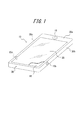
- FIG. 1 is an external perspective view showing a schematic configuration of a measuring apparatus according to an embodiment of the present invention.
- Measuring apparatus 10 may be a dedicated measuring apparatus that measures biological information of a subject, or may be one that uses an electronic device such as a mobile phone as measuring apparatus 10 according to the present embodiment.
- the measuring apparatus 10 is not limited to a mobile phone, and can be realized in various electronic devices such as a portable music player, a notebook computer, a wristwatch, a tablet terminal, and a game machine.
- the measuring apparatus 10 includes a main body 30 whose external shape is a substantially rectangular shape.
- the input unit 19 and the panel 20 are arranged on the surface 30a side, and the display unit 18 is held on the lower side of the panel 20 as shown in FIG. Yes.
- the panel 20 includes a touch panel that detects contact, a cover panel that protects the display unit 18, and the like, and is formed of a synthetic resin such as glass or acrylic.
- the panel 20 has a rectangular shape, for example.
- the panel 20 may be a flat plate or a curved panel in which the surface 30a is smoothly inclined.
- the touch panel 20 is a touch panel, the touch of a subject's finger, pen, stylus pen, or the like is detected.
- any method such as a capacitance method, a resistance film method, a surface acoustic wave method (or an ultrasonic method), an infrared method, an electromagnetic induction method, and a load detection method can be used.
- panel 20 is a touch panel.
- the measuring apparatus 10 includes a contact portion 15b which is a part of a first measuring portion described later on the side surface 30b side which is one long side of the main body 30.
- the measuring device 10 is a part of the second measuring unit on the side surface 30c side, which is the other long side of the main body 30, at a position symmetrical to the contact portion 15b when the measuring device 10 is viewed from the surface 30a.
- a certain contact portion 15c is provided.
- the contact parts 15b and 15c are parts where a subject such as a finger is brought into contact with the subject in order to measure biological information.
- the input unit 19 receives an operation input from the subject, and includes an operation button (operation key), for example.
- the panel 20 can also accept an operation input from the subject by detecting a contact from the subject to a soft key or the like displayed on the display unit 18.
- the measuring device 10 measures biological information while being held by a subject.
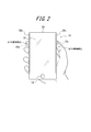
- FIG. 2 is a diagram illustrating a state where the subject holds the measuring apparatus 10 of FIG. 1 with the right hand.
- the abdominal portion of the index finger of the right hand contacts the contact portion 15b of the side surface 30b
- the abdominal portion of the thumb of the right hand contacts the contact portion 15c of the side surface 30c.
- the measuring apparatus 10 measures biological information in a state where two fingers are pressed against different contact portions 15b and 15c as shown in FIG.
- the biological information can be any biological information that can be measured using a biological sensor included in the measurement apparatus 10.
- the measurement device 10 will be described below as an example of measuring the blood flow of a subject, which is information related to blood flow.
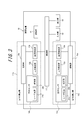
- FIG. 3 is a functional block diagram showing a schematic configuration of the measuring apparatus 10 of FIG.
- the measurement apparatus 10 includes a first measurement unit 11 b, a second measurement unit 11 c, a storage unit 16, a control unit 17, a display unit 18, and an input unit 19.
- the first measurement unit 11b includes a pressure detection unit 12b, a temperature detection unit 13b, a biological sensor 14b, and a contact unit 15b.
- the second measurement unit 11c includes a pressure detection unit 12c, a temperature detection unit 13c, a biological sensor 14c, and a contact unit 15c.
- the pressure detection units 12b and 12c, the temperature detection units 13b and 13c, the biological sensors 14b and 14c, and the contact units 15b and 15c have the same function.
- the biological sensor 14b includes a laser light source 21b and a light receiving unit 22b
- the biological sensor 14c includes a laser light source 21c and a light receiving unit 22c.
- the biosensors 14b and 14c are, for example, the same type of biosensor.
- the contact portion 15 b of the first measurement unit 11 b is disposed on the side surface 30 b of the main body 30, and the contact portion 15 c of the second measurement unit 11 c is disposed on the side surface 30 c of the main body 30.
- the functional units are simply the pressure detecting unit 12, the temperature detecting unit 13, and the biosensor. 14, a contact portion 15, a laser light source 21, and a light receiving portion 22.
- the pressure detection unit 12 detects the contact pressure of the test site that acts on the corresponding contact unit 15.
- the pressure detection unit 12 is configured by, for example, a piezoelectric element.
- the pressure detection unit 12 is connected to the control unit 17 and transmits the detected contact pressure to the control unit 17 as a pressure signal. Therefore, when the test site is in contact with the contact portion 15, the pressure detection unit 12 detects the contact pressure acting on the contact unit 15 from the test site, and uses the detected contact pressure as a pressure signal to the control unit 17. Send.
- the pressure detection unit 12b of the first measurement unit 11b detects the contact pressure acting on the contact unit 15b from the index finger of the right hand, and performs the second measurement.
- the pressure detector 12c of the part 11c detects contact pressure acting on the contact part 15c from the thumb of the right hand.
- the temperature detection unit 13 detects the temperature of the corresponding contact unit 15.
- the temperature detection part 13 is comprised by well-known temperature sensors, such as a thermocouple, a thermistor, a bimetal, for example.
- the temperature detection unit 13 is connected to the control unit 17 and transmits the detected temperature to the control unit 17 as a temperature signal. Accordingly, when the test site is in contact with the contact unit 15, the temperature detection unit 13 detects the temperature of the contact unit 15 based on the contact of the test site, and transmits the detected signal to the control unit 17 as a temperature signal. To do. When the subject holds the measuring apparatus 10 as shown in FIG.
- the temperature detection unit 13b of the first measurement unit 11b detects the temperature of the contact unit 15b based on the contact of the index finger of the right hand, and performs the second measurement.
- the temperature detection unit 13c of the unit 11c detects the temperature of the contact unit 15c based on the contact of the thumb of the right hand.
- the biological sensor 14 acquires a biological measurement output from a test site that contacts the contact portion 15.
- the biosensor 14b of the first measurement unit 11b acquires the biometric output from the index finger of the right hand, and the biosensor 14c of the second measurement unit 11c. Obtain biometric output from the thumb of the right hand.
- the laser light source 21 emits laser light based on the control of the control unit 17.
- the laser light source 21 irradiates, for example, a laser beam having a wavelength capable of detecting a predetermined component contained in blood as measurement light, and is configured by, for example, an LD (laser diode: Laser Diode). .
- LD laser diode: Laser Diode
- the light receiving unit 22 receives the scattered light of the measurement light from the test site as a biometric measurement output.
- the light receiving unit 22 is configured by, for example, a PD (photodiode: Photo Diode).
- the biological sensor 14 transmits a photoelectric conversion signal of scattered light received by the light receiving unit 22 to the control unit 17.
- the contact unit 15 is a part that contacts a test site such as a finger in order for the subject to measure biological information.
- the contact part 15 can be comprised by a plate-shaped member, for example.
- the contact portion 15 may be formed of a member that is transparent at least with respect to the measurement light and scattered light from the contacted test site.
- the storage unit 16 can be composed of a semiconductor memory, a magnetic memory, or the like, and stores various information, a program for operating the measuring apparatus 10, and the like, and also functions as a work memory.
- storage part 16 may memorize
- the control unit 17 is a processor that controls and manages the entire measurement apparatus 10 including each functional block of the measurement apparatus 10.
- the control unit 17 includes a processor such as a CPU (Central Processing Unit) that executes a program that defines a control procedure, and the program is stored in, for example, the storage unit 16 or an external storage medium.
- a processor such as a CPU (Central Processing Unit) that executes a program that defines a control procedure, and the program is stored in, for example, the storage unit 16 or an external storage medium.
- a CPU Central Processing Unit
- the control unit 17 causes the laser light sources 21b and 21c to irradiate the first and second test sites with laser light.
- the light receiving units 22b and 22c receive the scattered light from the first and second test sites to obtain a biometric output.
- the control unit 17 determines whether or not the biometric output from the biosensor 14 has been acquired. For example, the control unit 17 may determine that the acquisition of the biometric output is completed after a predetermined time has elapsed since the biosensor 14 started acquiring the biometric output. For example, the control unit 17 may determine that the acquisition of the biometric output is completed when the biosensor 14 acquires a sufficient biometric output for measuring the biometric information.
- the control unit 17 measures biological information based on the outputs (biological information output) of the plurality of pressure detection units 12b and 12c, the plurality of temperature detection units 13b and 13c, and the light receiving unit 22. For example, the control unit 17 selects either one of the plurality of biological sensors 14b or 14c based on the contact pressure obtained from the plurality of pressure detection units 12b and 12c and the temperature obtained from the plurality of temperature detection units 13b and 13c, respectively. Select.
- the biosensor 14 selection of the biosensor 14 based on the contact pressure obtained from each of the plurality of pressure detection units 12b and 12c will be described. For example, when the contact pressure at which the subject presses the contact parts 15b and 15c, that is, the contact pressures obtained from the plurality of pressure detection parts 12b and 12c are different, the measurement accuracy of the biological information measured based on the biometric output is also obtained. It is assumed that they are different.
- the controller 17 determines whether or not the contact pressure obtained from the pressure detectors 12b and 12c is within a range (allowable range) in which an error in the blood flow measurement result falls within a predetermined range.
- the control unit 17 detects the pressure detection unit 12b that detects the contact pressure within the allowable range or The biosensor 14b or 14c associated with 12c is selected.
- the control unit 17 determines the pressure detection unit 12b or 12c indicating the contact pressure with which the measurement error of biological information becomes smaller, The biosensor 14b or 14c associated with the determined pressure detector 12b or 12c is selected.
- the control unit 17 determines the pressure detection unit 12b or 12c indicating a contact pressure closer to the allowable range, and the determined pressure detection unit The biosensor 14b or 14c associated with 12b or 12c is selected.
- the control unit 17 measures biological information based on the biological measurement output obtained from the selected biological sensor 14b or 14c.
- the measuring apparatus 10 detects the contact pressure from a plurality of test sites, and when any one of the contact pressures is included in the allowable range, the pressure detection unit 12b that indicates the contact pressure included in the allowable range. Or the control part 17 measures biometric information based on the biosensor 14b or 14c matched with 12c. When the plurality of contact pressures are all within the allowable range or are all outside the allowable range, the control unit 17 corresponds to the pressure detection unit 12b or 12c indicating the contact pressure with which the measurement error of the biological information becomes smaller. Based on the attached biosensor 14b or 14c, the control unit 17 measures biometric information.
- the measurement apparatus 10 can easily obtain a highly accurate measurement result as compared with a case where biological information is measured based on one biological sensor.
- the measurement apparatus 10 includes a plurality of biosensors (two in the present embodiment), at least one of the contact pressures is within an allowable range compared to the case where biometric information is measured based on one biosensor. The possibility of being contained within can be increased.
- the controller 17 can further select the biosensor 14 based on the temperatures obtained from the plurality of temperature detectors 13b and 13c, respectively. Since it becomes difficult to output a highly accurate measurement result depending on the temperature of the test site, the control unit 17 is based on the temperature detected by the temperature detection units 13b and 13c in addition to the contact pressure described above. The biosensor 14b or 14c may be selected.
- the control unit 17 selects one biological sensor 14b or 14c based on both the contact pressure obtained from the plurality of pressure detection units 12b and 12c and the temperature obtained from the plurality of temperature detection units 13b and 13c, respectively. To do.
- the control unit 17 measures the biological information based on the biological measurement output obtained from the biological sensor 14b or 14c selected in this way, so that more accurate biological information is output as the measurement result from the measurement apparatus 10. I can expect that.
- the control unit 17 irradiates the living tissue (test site) with laser light from the laser light source 21 and receives the scattered light scattered from the living tissue by the light receiving unit 22. . And the control part 17 calculates a blood flow rate based on the output regarding the received scattered light.
- the control unit 17 detects a beat signal (also referred to as a beat signal) generated by light interference between scattered light from a stationary tissue and scattered light from a moving blood cell.
- This beat signal represents the intensity as a function of time.
- the control part 17 makes this beat signal the power spectrum which represented power as a function of frequency.
- the Doppler shift frequency is proportional to the blood cell velocity, and the power corresponds to the amount of blood cells.
- the control part 17 calculates
- the control unit 17 displays the biological information measured based on the biological measurement output obtained from the selected biological sensor 14b or 14c on the display unit 18.
- the subject can know the blood flow rate by checking the display on the display unit 18.
- the control unit 17 determines whether the biometric information is based on the biometric measurement output obtained from which biometric sensor 14b or 14c, that is, the index finger (first cover) that the biometric information contacts with the contact units 15b and 15c. It may be displayed which biometric output is based on (test site) or thumb (second test site). A subject who continuously measures biometric information can easily select a biometric output from any test site by checking the display, that is, a biometric output with high accuracy can be output from any test site. You can know whether it is easy to get.
- the control unit 17 measures the biological information based on the biological measurement output obtained from the biological sensor 14c or 14b not selected in addition to the biological information measured based on the biological measurement output obtained from the selected biological sensor 14b or 14c. May be.
- the control unit 17 provides the biological information measured based on the biological measurement output obtained from the biological sensor 14c or 14b not selected together with the biological information measured based on the biological measurement output obtained from the selected biological sensor 14b or 14c. It can be displayed on the display unit 18. In this case, the control unit 17 may display the selected biosensor 14b or 14c.
- the display unit 18 is a display device configured by a known display such as a liquid crystal display, an organic EL display, or an inorganic EL display.
- the display unit 18 displays the measured biological information, for example, under the control of the control unit 17.
- the control unit 17 of FIG. 1 performs blood flow. Is started when the state becomes measurable.
- the control unit 17 selects one selected biosensor 14b or 14c, and displays the biometric information measured based on the biometric output obtained from the selected biosensor 14b or 14c. 18 will be described.
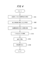
- the control unit 17 irradiates the test site with laser light from the laser light sources 21b and 21c, and acquires biometric measurement outputs from the biosensors 14b and 14c (step S101).
- the control unit 17 acquires the contact pressure at the contact units 15b and 15c detected by the pressure detection units 12b and 12c (step S102).
- the control part 17 acquires the temperature in the contact parts 15b and 15c which each temperature detection part 13b and 13c detected (step S103).
- control unit 17 selects one biological sensor 14b or 14c based on the acquired pressure and temperature (step S104).
- the control unit 17 measures the blood flow rate as biological information based on the biological measurement output obtained from the selected biological sensor 14b or 14c among the biological measurement outputs acquired in Step S101 (Step S105).
- the control unit 17 displays the blood flow volume as the measurement result measured in step S105 on the display unit 18 (step S106).
- the measuring apparatus 10 acquires biometric output of a plurality of test sites from the plurality of biosensors 14b and 14c. Based on the acquired pressure and temperature, the control unit 17 of the measurement apparatus 10 selects one biosensor 14b or 14c that can measure biometric information with higher accuracy, and is obtained from the selected biosensor 14b or 14c. Biometric information is measured based on the biometric output. Therefore, according to the measuring apparatus 10, the measurement accuracy of biological information is improved.
- the measuring device 10 outputs highly accurate biological information without causing the subject to measure the biological information again even when the contact portion 15b or 15c has a contact pressure outside the allowable range. it can.
- each component, each step, etc. can be rearranged so that there is no logical contradiction, and multiple components, steps, etc. can be combined or divided into one It is.
- the control unit 17 acquires biometric measurement outputs from the respective biosensors 14 b and 14 c (step S ⁇ b> 101), and thereafter, one biosensor 14 b based on the pressure and temperature of the contact units 15 b and 15 c.
- 14c is selected (step S104), but the control of the control unit 17 is not limited to this order.
- the controller 17 may first select one biosensor 14b or 14c based on the pressure and temperature of the contact portions 15b and 15c, and then cause the selected biosensor 14b or 14c to acquire a biometric output. Good.
- control unit 17 since the control unit 17 emits the laser light from only one laser light source 21b or 21c, the power consumption can be suppressed as compared with the case where the laser light is emitted from the plurality of laser light sources 21b and 21c. .
- the control unit 17 has one biosensor based on both the contact pressure obtained from the plurality of pressure detection units 12b and 12c and the temperature obtained from the plurality of temperature detection units 13b and 13c, respectively.
- the selection of the biosensor is not limited to such a method.
- the control unit 17 may select one biosensor 14b or 14c based only on the contact pressure detected by the pressure detection units 12b and 12c.
- the measurement apparatus 10 includes another detection unit that detects information for selecting one of the biosensors in order to improve the measurement accuracy of the biometric information, and the control unit 17 is based on information detected by the detection unit.
- One biological sensor may be selected.
- the measurement apparatus 10 includes the first and second measurement units 11b and 11c has been described, but the number of measurement units included in the measurement apparatus 10 is not limited to two.
- the measurement apparatus 10 may include three or more measurement units 11.
- the control unit 17 selects one biological sensor based on the contact pressure in the contact unit 15 included in each of the plurality of measurement units 11, and based on the biological measurement output acquired by the selected biological sensor, the biological information is obtained. taking measurement. It is expected that the greater the quantity of the measurement units 11, the higher the possibility that the contact pressure at any of the contact units is included in the allowable range.
- the measurement apparatus 10 may notify the subject of information on the strength of the contact pressure detected by the pressure detection units 12b and 12c.
- the information regarding the strength of the contact pressure is, for example, information regarding whether or not the contact pressure is within an allowable range.
- the information regarding the strength of the contact pressure may be information regarding whether the contact pressure is stronger or weaker than an allowable range, for example.
- the measuring apparatus 10 can report information on the strength of the contact pressure by, for example, a visual method using images, characters, light emission, or the like, an auditory method such as sound, or a combination thereof.
- the measurement apparatus 10 can notify information on the strength of the contact pressure from the display unit 18.
- the measurement device 10 may include a separate notification unit that performs notification of information related to the strength of the contact pressure, and may perform notification from the notification unit.
- the notification performed by the notification unit is not limited to a visual or auditory method, and may be any method that can be recognized by the user.
- the measurement device 10 reports information on the strength of the contact pressure, the subject can know the contact pressure when gripping the measurement device 10 and can easily adjust the contact pressure within an allowable range. .
- the contact portions 15b and 15c have been described as being disposed on the side surfaces 30b and 30c, respectively, but the arrangement of the contact portions 15b and 15c is not limited thereto.
- the contact portions 15b and 15c can be separately arranged at positions where a plurality of different fingers of the subject contact each other when the subject holds the main body 30 with one hand, for example.
- the contact portions 15b and 15c do not necessarily have to be arranged at positions assuming that the measuring device 10 is held with one hand.
- a plurality of different fingers may be separately arranged at positions where they contact each other.
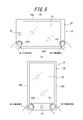
- FIG. 5 is a diagram illustrating an example of the arrangement of the contact portions 15 in the measurement apparatus 10.
- the contact portions 15 b and 15 c are disposed on the surface 30 a in the vicinity of one side surface 30 c and above and below the main body 30, respectively.
- the subject causes the left thumb abdomen to contact the contact portion 15b as the first test site, and the right thumb abdomen to contact the contact portion 15c as the second test site, Biometric information can be measured.
- the contact portions 15b and 15c are arranged on the surface 30a in the vicinity of the lower left and right side surfaces 30b and 30c, respectively.
- the subject causes the left thumb abdomen to contact the contact portion 15b as the first test site, and the right thumb abdomen to contact the contact portion 15c as the second test site, Biometric information can be measured.
- the measuring apparatus 10 is realized in an electronic device that is difficult to hold with one hand, such as a tablet terminal, it is effective to hold the measuring apparatus 10 with both hands in this way.
- control unit 17 has been described as measuring biological information based on the biological measurement output obtained from the selected biological sensor 14b or 14c. It is not limited to the method.
- the control unit 17 performs weighting determined by the pressures obtained from the plurality of pressure detection units 12b and 12c and the temperatures obtained from the plurality of temperature detection units 13b and 13c, thereby providing a plurality of biological sensors 14b and 14c.
- the biometric information may be measured (calculated) using a predetermined algorithm for synthesizing the biometric output obtained from the above.
- control unit 17 measures a plurality of pieces of biological information based on the biological measurement outputs respectively obtained from the plurality of biological sensors 14b and 14c, and displays a result of comparing the measured pieces of biological information on the display unit 18. May be.
- the result of comparison is, for example, a difference in blood flow for each of a plurality of test sites.
- the control unit 17 may measure a plurality of pieces of living body information based on the living body measurement outputs obtained from the plurality of living body sensors 14b and 14c, respectively, and may display the measured plurality of pieces of living body information on the display unit 18. At this time, the control unit 17 may display the biological information that is determined to have high measurement accuracy among the plurality of measured biological information on the display unit 18.
- the biological information determined to have high measurement accuracy is biological information that is considered to be more likely as the biological information of the user.
- the biological information is detected by the contact pressure and temperature detection unit 13 detected by the pressure detection unit 12. Determined by temperature.
- the control unit 17 includes information regarding whether or not the contact pressures detected by the pressure detection units 12b and 12c associated with the biometric sensors 14b and 14c respectively measuring a plurality of pieces of biometric information are included in an allowable range. It may be displayed.
- the control unit 17 Based on the pressure obtained from the pressure detection unit 12b or 12c or the temperature obtained from the temperature detection unit 13b or 13c, the control unit 17 is in contact with only one of the contact units 15b or 15c.
- the biological information may be measured based on the biological measurement output from the biological sensor 14b or 14c corresponding to the contact portion 15b or 15c determined to be in contact.
- the measuring apparatus 10 may further include a contact detection sensor in the vicinity of each of the plurality of contact portions 15b and 15c.
- the contact detection sensor is a sensor that detects contact of a subject's test site, and is, for example, a touch sensor, a pressure sensor, a temperature sensor, or the like.
- the control unit 17 is configured to receive an operation input from the subject by detecting a contact from the subject to a soft key or the like displayed on the display unit 18, each of the contact detection sensors An image is displayed on the display unit 18 based on the positions of the contact portions 15b and 15c located in the vicinity and the output from the contact detection sensor. For example, it is assumed that the contact portions 15b and 15c are arranged at the position shown in FIG.
- the control unit 17 determines that the subject is holding the measuring apparatus 10 with the right hand. And the control part 17 arrange
- the right side of the display unit 18 means, for example, the right side with respect to the center of the display unit 18 in a state where the user holds the measuring device 10.
- the control unit 17 determines that the subject is holding the measuring device 10 with the left hand, and displays the display unit 18 on the display unit 18.
- the displayed soft key is arranged on the left side of the display unit 18, for example.
- the left side of the display unit 18 means, for example, the left side with respect to the center of the display unit 18 in a state where the user holds the measuring device 10. Accordingly, when the subject measures biological information using the measuring device 10 and then performs another operation using the measuring device 10 while holding the measuring device 10, the display unit 18 Since the soft keys displayed on the screen are arranged near the finger to be operated, the operation becomes easy.
- the pressure detection unit 12 or the temperature detection unit 13 may function as a contact detection sensor.
- control unit 17 of the measurement apparatus 10 has been described as measuring biological information, but measurement of biological information is not limited to the case where the control unit 17 of the measurement apparatus 10 performs measurement.
- a measurement terminal including the measurement unit 11 transmits a biometric measurement output acquired by the biometric sensor 14 to a server device connected to the measurement terminal via a network that is wired, wireless, or a combination thereof.
- a server apparatus is provided with the server control part which performs control similar to the control part 17 of the said embodiment, and a server control part measures biometric information based on a biometric measurement output.
- the measurement result is transmitted from the server device to the measurement terminal and displayed on the display unit of the measurement terminal, for example.
Landscapes
- Health & Medical Sciences (AREA)
- Life Sciences & Earth Sciences (AREA)
- Heart & Thoracic Surgery (AREA)
- Medical Informatics (AREA)
- Physics & Mathematics (AREA)
- Veterinary Medicine (AREA)
- Biophysics (AREA)
- Pathology (AREA)
- Engineering & Computer Science (AREA)
- Biomedical Technology (AREA)
- Public Health (AREA)
- General Health & Medical Sciences (AREA)
- Molecular Biology (AREA)
- Surgery (AREA)
- Animal Behavior & Ethology (AREA)
- Physiology (AREA)
- Hematology (AREA)
- Cardiology (AREA)
- Measuring Pulse, Heart Rate, Blood Pressure Or Blood Flow (AREA)
- Measuring And Recording Apparatus For Diagnosis (AREA)
Abstract
This measurement device is provided with: multiple contact units (16b, 16c) which are arranged on a main body so as to enable contact at multiple measured sites on a patient; multiple biological sensors (14b and 14c) which acquire biometric output at the measurement sites in contact with the multiple contact units (16b and 16c); multiple pressure detection units (12b and 12c) which detect the pressure acting on the multiple contact units (14b and 14c); and a control unit (17) which measures biometric information on the basis of the pressures obtained from the pressure detection units (12b and 12c) and the biometric output obtained from the biometric sensors (14b and 14c).
Description
本出願は、日本国特許出願2014-124413号(2014年6月17日出願)の優先権を主張するものであり、当該出願の開示全体を、ここに参照のために取り込む。
This application claims the priority of Japanese Patent Application No. 2014-124413 (filed on June 17, 2014), the entire disclosure of which is incorporated herein by reference.
本発明は、測定装置及び測定方法に関する。
The present invention relates to a measuring apparatus and a measuring method.
従来、被検者の指先等の被検部位から生体出力情報を取得して、生体情報を測定する測定装置が知られている。例えば、生体情報として血流を測定する血流測定装置は、レーザ光を指先に照射し、指先の毛細血管の血流からの散乱光に基づいて血流を測定する(例えば、特許文献1参照)。
2. Description of the Related Art Conventionally, a measuring device that acquires biological output information from a test site such as a fingertip of a subject and measures the biological information is known. For example, a blood flow measuring device that measures blood flow as biological information irradiates a fingertip with a laser beam and measures blood flow based on scattered light from blood flow of capillaries at the fingertip (see, for example, Patent Document 1). ).
しかしながら、生体情報の測定結果は、被検部位から測定装置を押さえる圧力によって変化しやすい。生体情報の測定結果の誤差が許容できる範囲を超える場合、被検者は、生体情報を測定しなおす必要があり、煩わしさを感じる場合がある。
However, the measurement result of biological information is likely to change depending on the pressure with which the measurement device is pressed from the test site. If the error in the measurement result of the biological information exceeds an allowable range, the subject needs to measure the biological information again and may feel annoyed.
かかる事情に鑑みてなされた本発明の目的は、改善された測定装置及び測定方法を提供することにある。
An object of the present invention made in view of such circumstances is to provide an improved measuring apparatus and measuring method.
上記目的を達成する本発明に係る測定装置は、
被検者の複数の被検部位が接触可能に本体に配置された複数の接触部と、
前記複数の接触部に接触される前記被検部位の生体測定出力をそれぞれ取得する複数の生体センサと、
前記複数の接触部に作用する圧力をそれぞれ検出する複数の圧力検出部と、
前記複数の圧力検出部からそれぞれ得られる前記圧力及び前記複数の生体センサからそれぞれ得られる前記生体測定出力に基づいて生体情報を測定する制御部とを備える。 A measuring apparatus according to the present invention that achieves the above object,
A plurality of contact portions arranged on the main body so that a plurality of test sites of the subject can be contacted; and
A plurality of biosensors that respectively obtain biometric output of the test site in contact with the plurality of contact parts;
A plurality of pressure detectors for respectively detecting pressure acting on the plurality of contact portions;
A control unit that measures biometric information based on the pressure obtained from the plurality of pressure detection units and the biometric measurement output obtained from the plurality of biometric sensors, respectively.
前記制御部は、前記複数の圧力検出部からそれぞれ得られる前記圧力に基づいて前記複数の生体センサのいずれか1つを選択し、該選択した生体センサから得られる前記生体測定出力に基づいて前記生体情報を測定するものであってもよい。
The control unit selects any one of the plurality of biosensors based on the pressure obtained from the plurality of pressure detection units, and based on the biometric output obtained from the selected biosensor. Biometric information may be measured.
また、上記目的を達成する本発明に係る測定装置は、
被検者の複数の被検部位が接触可能に本体に配置された複数の接触部と、
前記複数の接触部に接触される前記被検部位の生体測定出力をそれぞれ取得する複数の生体センサと、
前記複数の接触部に作用する圧力をそれぞれ検出する複数の圧力検出部と、
前記複数の接触部の温度をそれぞれ検出する複数の温度検出部と、
前記複数の圧力検出部からそれぞれ得られる前記圧力、前記複数の温度検出部からそれぞれ得られる前記温度及び前記複数の生体センサからそれぞれ得られる前記生体測定出力に基づいて生体情報を測定する制御部とを備える。 In addition, the measuring device according to the present invention that achieves the above-described object,
A plurality of contact portions arranged on the main body so that a plurality of test sites of the subject can be contacted; and
A plurality of biosensors that respectively obtain biometric output of the test site in contact with the plurality of contact parts;
A plurality of pressure detectors for respectively detecting pressure acting on the plurality of contact portions;
A plurality of temperature detectors for detecting temperatures of the plurality of contact portions, respectively;
A control unit that measures biometric information based on the pressure obtained from the plurality of pressure detection units, the temperature obtained from the plurality of temperature detection units, and the biometric output obtained from the plurality of biometric sensors, respectively. Is provided.
前記制御部は、前記複数の圧力検出部からそれぞれ得られる前記圧力及び前記複数の温度検出部からそれぞれ得られる前記温度に基づいて前記複数の生体センサのいずれか1つを選択し、該選択した生体センサから得られる前記生体測定出力に基づいて前記生体情報を測定するものであってもよい。
The control unit selects one of the plurality of biosensors based on the pressure obtained from the plurality of pressure detection units and the temperature respectively obtained from the plurality of temperature detection units, and the selected The biological information may be measured based on the biological measurement output obtained from the biological sensor.
表示部をさらに備え、
前記制御部は、前記測定した生体情報を前記表示部に表示してもよい。 A display unit;
The control unit may display the measured biological information on the display unit.
前記制御部は、前記測定した生体情報を前記表示部に表示してもよい。 A display unit;
The control unit may display the measured biological information on the display unit.
表示部をさらに備え、
前記制御部は、前記複数の生体センサからそれぞれ得られる前記生体測定出力に基づいて複数の生体情報を測定すると共に、該複数の生体情報を前記表示部に表示してもよい。 A display unit;
The control unit may measure a plurality of pieces of biological information based on the biological measurement outputs obtained from the plurality of biological sensors, and display the plurality of pieces of biological information on the display unit.
前記複数の接触部は、被検者が前記本体を片手で把持したときに前記被検者の複数の異なる指がそれぞれ接触する位置に分離して配置されてもよい。
The plurality of contact portions may be separately arranged at positions where a plurality of different fingers of the subject contact each other when the subject grips the main body with one hand.
前記複数の接触部は、被検者が前記本体を両手で把持したときに前記被検者の異なる手の指がそれぞれ接触する位置に分離して配置されてもよい。
The plurality of contact portions may be separately disposed at positions where fingers of different hands of the subject contact each other when the subject grips the main body with both hands.
表示部をさらに備え、
前記制御部は、前記複数の生体センサからそれぞれ得られる前記生体測定出力に基づいて複数の生体情報を測定し、前記複数の生体情報を比較した結果を前記表示部に表示してもよい。 A display unit;
The control unit may measure a plurality of pieces of biological information based on the biological measurement outputs respectively obtained from the plurality of biological sensors, and display a result of comparing the plurality of pieces of biological information on the display unit.
表示部と、
前記複数の接触部それぞれの近傍に配置され、被検者の被検部位の接触を検知する複数の接触検知センサとをさらに備え、
前記制御部は、前記接触部が配置された位置及び前記接触検知センサからの出力に基づいて、前記表示部に画像を表示してもよい。 A display unit;
A plurality of contact detection sensors arranged in the vicinity of each of the plurality of contact portions, and further detecting a contact of the subject's test site;
The control unit may display an image on the display unit based on a position where the contact unit is arranged and an output from the contact detection sensor.
前記生体情報は、血流に関する情報を含んでいてもよい。
The biological information may include information related to blood flow.
上述したように本発明の解決手段を装置として説明してきたが、本発明はこれらに実質的に相当する方法としても実現し得るものであり、本発明の範囲にはこれらも包含されるものと理解されたい。
As described above, the solution of the present invention has been described as an apparatus, but the present invention can be realized as a method substantially corresponding to these, and the scope of the present invention also includes these. I want you to understand.
例えば、本発明に係る測定方法は、
複数の被検部位を複数の接触部に接触させて生体情報を測定するにあたり、
前記複数の接触部に接触される前記複数の被検部位から、生体センサにより複数の生体測定出力をそれぞれ取得する取得ステップと、
前記複数の接触部に作用する圧力を、複数の圧力検出部によりそれぞれ検出する圧力検出ステップと、
前記圧力検出ステップにおいて得られる前記圧力及び前記取得ステップにおいて得られる前記生体測定出力に基づいて、制御部により前記生体情報を測定する測定ステップとを含む。 For example, the measuring method according to the present invention is:
In measuring biological information by contacting multiple test sites with multiple contact parts,
An acquisition step of acquiring a plurality of biometric measurement outputs by a biosensor from the plurality of test sites in contact with the plurality of contact parts,
A pressure detection step of detecting pressure acting on the plurality of contact portions by a plurality of pressure detection portions;
A measurement step of measuring the biological information by a control unit based on the pressure obtained in the pressure detection step and the biological measurement output obtained in the acquisition step.
上記のように構成された本発明によれば、改善された測定装置及び測定方法を提供できる。
According to the present invention configured as described above, an improved measuring apparatus and measuring method can be provided.
以下、本発明の一実施の形態について、図面を参照して詳細に説明する。
Hereinafter, an embodiment of the present invention will be described in detail with reference to the drawings.
図1は、本発明の一実施の形態に係る測定装置の概略構成を示す外観斜視図である。測定装置10は、被検者の生体情報を測定する専用の測定装置であってもよく、携帯電話機等の電子機器を本実施の形態に係る測定装置10として使用したものであってもよい。測定装置10は、携帯電話機に限られず、例えば、携帯型ミュージックプレイヤ、ノートパソコン、腕時計、タブレット端末、ゲーム機などの多岐にわたる任意の電子機器においても実現できる。
FIG. 1 is an external perspective view showing a schematic configuration of a measuring apparatus according to an embodiment of the present invention. Measuring apparatus 10 may be a dedicated measuring apparatus that measures biological information of a subject, or may be one that uses an electronic device such as a mobile phone as measuring apparatus 10 according to the present embodiment. The measuring apparatus 10 is not limited to a mobile phone, and can be realized in various electronic devices such as a portable music player, a notebook computer, a wristwatch, a tablet terminal, and a game machine.
本実施の形態に係る測定装置10は、外観形状が概略長方形状を成す本体30を備える。本体30には、表面30a側に入力部19及びパネル20が配置されており、パネル20の下側に図1にパネル20の一部を切り欠いて示すように、表示部18が保持されている。
The measuring apparatus 10 according to the present embodiment includes a main body 30 whose external shape is a substantially rectangular shape. In the main body 30, the input unit 19 and the panel 20 are arranged on the surface 30a side, and the display unit 18 is held on the lower side of the panel 20 as shown in FIG. Yes.
パネル20は、接触を検出するタッチパネル、または表示部18を保護するカバーパネル等からなり、例えばガラス、又はアクリル等の合成樹脂により形成される。パネル20は、例えば長方形状である。パネル20は、平板であってもよいし、表面30aが滑らかに傾斜する曲面パネルであってもよい。パネル20は、タッチパネルである場合、被検者の指、ペン、又はスタイラスペン等の接触を検出する。タッチパネルの検出方式は、静電容量方式、抵抗膜方式、表面弾性波方式(又は超音波方式)、赤外線方式、電磁誘導方式、及び荷重検出方式等の任意の方式を用いることができる。本実施の形態では、説明の便宜上、パネル20は、タッチパネルとする。
The panel 20 includes a touch panel that detects contact, a cover panel that protects the display unit 18, and the like, and is formed of a synthetic resin such as glass or acrylic. The panel 20 has a rectangular shape, for example. The panel 20 may be a flat plate or a curved panel in which the surface 30a is smoothly inclined. When the panel 20 is a touch panel, the touch of a subject's finger, pen, stylus pen, or the like is detected. As a detection method of the touch panel, any method such as a capacitance method, a resistance film method, a surface acoustic wave method (or an ultrasonic method), an infrared method, an electromagnetic induction method, and a load detection method can be used. In the present embodiment, for convenience of explanation, panel 20 is a touch panel.
本実施の形態に係る測定装置10は、本体30の一方の長辺である側面30b側に、後述する第1の測定部の一部である接触部15bを備える。測定装置10は、本体30の他方の長辺である側面30c側に、測定装置10を表面30aから見たときに接触部15bと左右対称となる位置に、第2の測定部の一部である接触部15cを備える。接触部15b及び15cは、被検者が生体情報を測定するために、指等の被検部位を接触させる部分である。
The measuring apparatus 10 according to the present embodiment includes a contact portion 15b which is a part of a first measuring portion described later on the side surface 30b side which is one long side of the main body 30. The measuring device 10 is a part of the second measuring unit on the side surface 30c side, which is the other long side of the main body 30, at a position symmetrical to the contact portion 15b when the measuring device 10 is viewed from the surface 30a. A certain contact portion 15c is provided. The contact parts 15b and 15c are parts where a subject such as a finger is brought into contact with the subject in order to measure biological information.
入力部19は、被検者からの操作入力を受け付けるものであり、例えば、操作ボタン(操作キー)から構成される。パネル20も表示部18に表示されるソフトキー等への被検者からの接触を検出することにより、被検者からの操作入力を受け付けることができる。
The input unit 19 receives an operation input from the subject, and includes an operation button (operation key), for example. The panel 20 can also accept an operation input from the subject by detecting a contact from the subject to a soft key or the like displayed on the display unit 18.
測定装置10は、被検者により把持された状態で生体情報の測定を行う。図2は、図1の測定装置10を被検者が右手で把持した状態を示す図である。この場合、例えば図2に示すように、右手の人差し指の腹の部分が側面30bの接触部15bに接触し、右手の親指の腹の部分が側面30cの接触部15cに接触する。測定装置10は、図2のように2本の指がそれぞれ異なる接触部15b及び15cに押し当てられた状態において、生体情報を測定する。生体情報は、測定装置10が備える生体センサを使用して測定可能な任意の生体情報とすることができる。本実施の形態においては、測定装置10は、一例として、血流に関する情報である被検者の血流量を測定するものとして、以下説明を行う。
The measuring device 10 measures biological information while being held by a subject. FIG. 2 is a diagram illustrating a state where the subject holds the measuring apparatus 10 of FIG. 1 with the right hand. In this case, for example, as shown in FIG. 2, the abdominal portion of the index finger of the right hand contacts the contact portion 15b of the side surface 30b, and the abdominal portion of the thumb of the right hand contacts the contact portion 15c of the side surface 30c. The measuring apparatus 10 measures biological information in a state where two fingers are pressed against different contact portions 15b and 15c as shown in FIG. The biological information can be any biological information that can be measured using a biological sensor included in the measurement apparatus 10. In the present embodiment, the measurement device 10 will be described below as an example of measuring the blood flow of a subject, which is information related to blood flow.
図3は、図1の測定装置10の概略構成を示す機能ブロック図である。図3に示すように、測定装置10は、第1の測定部11bと、第2の測定部11cと、記憶部16と、制御部17と、表示部18と、入力部19とを備える。第1の測定部11bは、圧力検出部12bと、温度検出部13bと、生体センサ14bと、接触部15bとを備える。第2の測定部11cは、圧力検出部12cと、温度検出部13cと、生体センサ14cと、接触部15cとを備える。圧力検出部12b及び12c、温度検出部13b及び13c、生体センサ14b及び14c、並びに接触部15b及び15cは、それぞれ同一の機能を有する。生体センサ14bは、レーザ光源21bと受光部22bとを有し、生体センサ14cは、レーザ光源21cと受光部22cとを有する。生体センサ14bと14cとは、例えば同種の生体センサである。第1の測定部11bの接触部15bは、本体30の側面30bに配置され、第2の測定部11cの接触部15cは、本体30の側面30cに配置される。以下、各機能部が第1の測定部11b又は第2の測定部11cのいずれに含まれるかを区別しない場合には、各機能部を、単に圧力検出部12、温度検出部13、生体センサ14、接触部15、レーザ光源21及び受光部22と示す。
FIG. 3 is a functional block diagram showing a schematic configuration of the measuring apparatus 10 of FIG. As shown in FIG. 3, the measurement apparatus 10 includes a first measurement unit 11 b, a second measurement unit 11 c, a storage unit 16, a control unit 17, a display unit 18, and an input unit 19. The first measurement unit 11b includes a pressure detection unit 12b, a temperature detection unit 13b, a biological sensor 14b, and a contact unit 15b. The second measurement unit 11c includes a pressure detection unit 12c, a temperature detection unit 13c, a biological sensor 14c, and a contact unit 15c. The pressure detection units 12b and 12c, the temperature detection units 13b and 13c, the biological sensors 14b and 14c, and the contact units 15b and 15c have the same function. The biological sensor 14b includes a laser light source 21b and a light receiving unit 22b, and the biological sensor 14c includes a laser light source 21c and a light receiving unit 22c. The biosensors 14b and 14c are, for example, the same type of biosensor. The contact portion 15 b of the first measurement unit 11 b is disposed on the side surface 30 b of the main body 30, and the contact portion 15 c of the second measurement unit 11 c is disposed on the side surface 30 c of the main body 30. Hereinafter, when it is not distinguished whether each functional unit is included in the first measuring unit 11b or the second measuring unit 11c, the functional units are simply the pressure detecting unit 12, the temperature detecting unit 13, and the biosensor. 14, a contact portion 15, a laser light source 21, and a light receiving portion 22.
圧力検出部12は、対応する接触部15にそれぞれ作用する被検部位の接触圧力を検出する。圧力検出部12は、例えば圧電素子により構成される。圧力検出部12は、制御部17に接続されており、検出した接触圧力を圧力信号として制御部17に送信する。従って、圧力検出部12は、接触部15に被検部位が接触している場合、被検部位から接触部15に作用する接触圧力を検出し、検出した接触圧力を圧力信号として制御部17に送信する。被検者が図2のように測定装置10を把持した場合、第1の測定部11bの圧力検出部12bは、右手の人差し指から接触部15bに作用する接触圧力を検出し、第2の測定部11cの圧力検出部12cは、右手の親指から接触部15cに作用する接触圧力を検出する。
The pressure detection unit 12 detects the contact pressure of the test site that acts on the corresponding contact unit 15. The pressure detection unit 12 is configured by, for example, a piezoelectric element. The pressure detection unit 12 is connected to the control unit 17 and transmits the detected contact pressure to the control unit 17 as a pressure signal. Therefore, when the test site is in contact with the contact portion 15, the pressure detection unit 12 detects the contact pressure acting on the contact unit 15 from the test site, and uses the detected contact pressure as a pressure signal to the control unit 17. Send. When the subject holds the measuring device 10 as shown in FIG. 2, the pressure detection unit 12b of the first measurement unit 11b detects the contact pressure acting on the contact unit 15b from the index finger of the right hand, and performs the second measurement. The pressure detector 12c of the part 11c detects contact pressure acting on the contact part 15c from the thumb of the right hand.
温度検出部13は、対応する接触部15の温度を検出する。温度検出部13は、例えば熱電対、サーミスタ、バイメタル等の周知の温度センサにより構成される。温度検出部13は、制御部17に接続されており、検出した温度を温度信号として制御部17に送信する。従って、温度検出部13は、接触部15に被検部位が接触している場合、被検部位の接触に基づく接触部15の温度を検出し、検出した信号を温度信号として制御部17に送信する。被検者が図2のように測定装置10を把持した場合、第1の測定部11bの温度検出部13bは、右手の人差し指の接触に基づく接触部15bの温度を検出し、第2の測定部11cの温度検出部13cは、右手の親指の接触に基づく接触部15cの温度を検出する。
The temperature detection unit 13 detects the temperature of the corresponding contact unit 15. The temperature detection part 13 is comprised by well-known temperature sensors, such as a thermocouple, a thermistor, a bimetal, for example. The temperature detection unit 13 is connected to the control unit 17 and transmits the detected temperature to the control unit 17 as a temperature signal. Accordingly, when the test site is in contact with the contact unit 15, the temperature detection unit 13 detects the temperature of the contact unit 15 based on the contact of the test site, and transmits the detected signal to the control unit 17 as a temperature signal. To do. When the subject holds the measuring apparatus 10 as shown in FIG. 2, the temperature detection unit 13b of the first measurement unit 11b detects the temperature of the contact unit 15b based on the contact of the index finger of the right hand, and performs the second measurement. The temperature detection unit 13c of the unit 11c detects the temperature of the contact unit 15c based on the contact of the thumb of the right hand.
生体センサ14は、接触部15に接触する被検部位から生体測定出力を取得する。被検者が図2のように測定装置10を把持した場合、第1の測定部11bの生体センサ14bは、右手の人差し指から生体測定出力を取得し、第2の測定部11cの生体センサ14cは、右手の親指から生体測定出力を取得する。
The biological sensor 14 acquires a biological measurement output from a test site that contacts the contact portion 15. When the subject holds the measuring apparatus 10 as shown in FIG. 2, the biosensor 14b of the first measurement unit 11b acquires the biometric output from the index finger of the right hand, and the biosensor 14c of the second measurement unit 11c. Obtain biometric output from the thumb of the right hand.
レーザ光源21は、制御部17の制御に基づいてレーザ光を射出する。レーザ光源21は、例えば、血液中に含まれる所定の成分を検出可能な波長のレーザ光を、測定光として被検部位に照射するもので、例えばLD(レーザダイオード:Laser Diode)により構成される。
The laser light source 21 emits laser light based on the control of the control unit 17. The laser light source 21 irradiates, for example, a laser beam having a wavelength capable of detecting a predetermined component contained in blood as measurement light, and is configured by, for example, an LD (laser diode: Laser Diode). .
受光部22は、生体測定出力として、被検部位からの測定光の散乱光を受光する。受光部22は、例えば、PD(フォトダイオード:Photo Diode)により構成される。生体センサ14は、受光部22において受光した散乱光の光電変換信号を制御部17に送信する。
The light receiving unit 22 receives the scattered light of the measurement light from the test site as a biometric measurement output. The light receiving unit 22 is configured by, for example, a PD (photodiode: Photo Diode). The biological sensor 14 transmits a photoelectric conversion signal of scattered light received by the light receiving unit 22 to the control unit 17.
接触部15は、上述のように、被検者が生体情報を測定するために、指等の被検部位を接触させる部分である。接触部15は、例えば、板状の部材により構成できる。接触部15は、少なくとも測定光及び接触する被検部位からの散乱光に対して透明な部材により構成してもよい。
As described above, the contact unit 15 is a part that contacts a test site such as a finger in order for the subject to measure biological information. The contact part 15 can be comprised by a plate-shaped member, for example. The contact portion 15 may be formed of a member that is transparent at least with respect to the measurement light and scattered light from the contacted test site.
記憶部16は、半導体メモリ又は磁気メモリ等で構成することができ、各種情報や測定装置10を動作させるためのプログラム等を記憶するとともに、ワークメモリとしても機能する。記憶部16は、例えば、測定装置10が測定した血流量を、履歴として記憶してもよい。
The storage unit 16 can be composed of a semiconductor memory, a magnetic memory, or the like, and stores various information, a program for operating the measuring apparatus 10, and the like, and also functions as a work memory. The memory | storage part 16 may memorize | store the blood flow rate which the measuring apparatus 10 measured as a log | history, for example.
制御部17は、測定装置10の各機能ブロックをはじめとして、測定装置10の全体を制御及び管理するプロセッサである。制御部17は、制御手順を規定したプログラムを実行するCPU(Central Processing Unit)等のプロセッサで構成され、かかるプログラムは、例えば記憶部16又は外部の記憶媒体等に格納される。
The control unit 17 is a processor that controls and manages the entire measurement apparatus 10 including each functional block of the measurement apparatus 10. The control unit 17 includes a processor such as a CPU (Central Processing Unit) that executes a program that defines a control procedure, and the program is stored in, for example, the storage unit 16 or an external storage medium.
制御部17は、レーザ光源21b及び21cから第1及び第2の被検部位にレーザ光を照射させる。受光部22b及び22cは、第1及び第2の被検部位からの散乱光を受光することにより、生体測定出力を取得する。制御部17は、生体センサ14による生体測定出力の取得が終了したか否かを判定する。制御部17は、例えば、生体センサ14が生体測定出力の取得を開始してから、所定時間経過後に、生体測定出力の取得が終了したと判断してもよい。制御部17は、例えば、生体センサ14が、生体情報を測定するために十分な生体測定出力を取得したとき、生体測定出力の取得が終了したと判断してもよい。
The control unit 17 causes the laser light sources 21b and 21c to irradiate the first and second test sites with laser light. The light receiving units 22b and 22c receive the scattered light from the first and second test sites to obtain a biometric output. The control unit 17 determines whether or not the biometric output from the biosensor 14 has been acquired. For example, the control unit 17 may determine that the acquisition of the biometric output is completed after a predetermined time has elapsed since the biosensor 14 started acquiring the biometric output. For example, the control unit 17 may determine that the acquisition of the biometric output is completed when the biosensor 14 acquires a sufficient biometric output for measuring the biometric information.
制御部17は、複数の圧力検出部12b及び12c、複数の温度検出部13b及び13c、並びに受光部22の出力(生体情報出力)に基づいて、生体情報を測定する。例えば、制御部17は、複数の圧力検出部12b及び12cからそれぞれ得られる接触圧力及び複数の温度検出部13b及び13cからそれぞれ得られる温度に基づいて、複数の生体センサ14b又は14cのいずれか一方を選択する。
The control unit 17 measures biological information based on the outputs (biological information output) of the plurality of pressure detection units 12b and 12c, the plurality of temperature detection units 13b and 13c, and the light receiving unit 22. For example, the control unit 17 selects either one of the plurality of biological sensors 14b or 14c based on the contact pressure obtained from the plurality of pressure detection units 12b and 12c and the temperature obtained from the plurality of temperature detection units 13b and 13c, respectively. Select.
ここで、複数の圧力検出部12b及び12cからそれぞれ得られる接触圧力に基づく生体センサ14の選択について説明する。例えば、被検者が接触部15b及び15cを押さえる接触圧力、すなわち複数の圧力検出部12b及び12cからそれぞれ得られる接触圧力が異なる場合、生体測定出力に基づいて測定される生体情報の測定精度も異なることが想定される。制御部17は、圧力検出部12b及び12cから得られる接触圧力が、血流量の測定結果の誤差が所定の範囲内に収まる範囲(許容範囲)内であるか否かを判断する。
Here, selection of the biosensor 14 based on the contact pressure obtained from each of the plurality of pressure detection units 12b and 12c will be described. For example, when the contact pressure at which the subject presses the contact parts 15b and 15c, that is, the contact pressures obtained from the plurality of pressure detection parts 12b and 12c are different, the measurement accuracy of the biological information measured based on the biometric output is also obtained. It is assumed that they are different. The controller 17 determines whether or not the contact pressure obtained from the pressure detectors 12b and 12c is within a range (allowable range) in which an error in the blood flow measurement result falls within a predetermined range.
制御部17は、圧力検出部12b及び12cから得られる接触圧力のうち、一方が許容範囲内であり、他方が許容範囲外である場合、許容範囲内の接触圧力を検出した圧力検出部12b又は12cに対応付けられた生体センサ14b又は14cを選択する。制御部17は、圧力検出部12b及び12cから得られる接触圧力が、双方とも許容範囲内である場合、生体情報の測定誤差がより小さくなる接触圧力を示す圧力検出部12b又は12cを決定し、決定した圧力検出部12b又は12cに対応付けられた生体センサ14b又は14cを選択する。制御部17は、圧力検出部12b及び12cから得られる接触圧力が、双方とも許容範囲外である場合、許容範囲により近い接触圧力を示す圧力検出部12b又は12cを決定し、決定した圧力検出部12b又は12cに対応付けられた生体センサ14b又は14cを選択する。制御部17は、選択した生体センサ14b又は14cから得られる生体測定出力に基づいて、生体情報を測定する。
When one of the contact pressures obtained from the pressure detection units 12b and 12c is within the allowable range and the other is out of the allowable range, the control unit 17 detects the pressure detection unit 12b that detects the contact pressure within the allowable range or The biosensor 14b or 14c associated with 12c is selected. When the contact pressure obtained from the pressure detection units 12b and 12c is both within the allowable range, the control unit 17 determines the pressure detection unit 12b or 12c indicating the contact pressure with which the measurement error of biological information becomes smaller, The biosensor 14b or 14c associated with the determined pressure detector 12b or 12c is selected. When the contact pressures obtained from the pressure detection units 12b and 12c are both outside the allowable range, the control unit 17 determines the pressure detection unit 12b or 12c indicating a contact pressure closer to the allowable range, and the determined pressure detection unit The biosensor 14b or 14c associated with 12b or 12c is selected. The control unit 17 measures biological information based on the biological measurement output obtained from the selected biological sensor 14b or 14c.
このように、測定装置10は、複数の被検部位からの接触圧力を検出し、いずれかの接触圧力が許容範囲内に含まれる場合に、許容範囲に含まれる接触圧力を示す圧力検出部12b又は12cに対応付けられた生体センサ14b又は14cに基づいて、制御部17が生体情報を測定する。複数の接触圧力が、全て許容範囲内である場合又は全て許容範囲外である場合には、制御部17は、生体情報の測定誤差がより小さくなる接触圧力を示す圧力検出部12b又は12cに対応付けられた生体センサ14b又は14cに基づいて、制御部17が生体情報を測定する。そのため、測定装置10は、1つの生体センサに基づいて生体情報を測定する場合と比較して、精度の高い測定結果を得やすい。また、測定装置10は、生体センサを複数(本実施の形態では2つ)備えるため、1つの生体センサに基づいて生体情報を測定する場合と比較して、少なくともいずれかの接触圧力が許容範囲内に含まれる可能性を高めることができる。
Thus, the measuring apparatus 10 detects the contact pressure from a plurality of test sites, and when any one of the contact pressures is included in the allowable range, the pressure detection unit 12b that indicates the contact pressure included in the allowable range. Or the control part 17 measures biometric information based on the biosensor 14b or 14c matched with 12c. When the plurality of contact pressures are all within the allowable range or are all outside the allowable range, the control unit 17 corresponds to the pressure detection unit 12b or 12c indicating the contact pressure with which the measurement error of the biological information becomes smaller. Based on the attached biosensor 14b or 14c, the control unit 17 measures biometric information. Therefore, the measurement apparatus 10 can easily obtain a highly accurate measurement result as compared with a case where biological information is measured based on one biological sensor. In addition, since the measurement apparatus 10 includes a plurality of biosensors (two in the present embodiment), at least one of the contact pressures is within an allowable range compared to the case where biometric information is measured based on one biosensor. The possibility of being contained within can be increased.
制御部17は、さらに複数の温度検出部13b及び13cからそれぞれ得られる温度に基づいて生体センサ14を選択できる。被検部位の温度によっては、精度の高い測定結果を出力することが難しくなるため、制御部17は、上述の接触圧力に加えて、温度検出部13b及び13cで検出される温度にも基づいて生体センサ14b又は14cを選択してもよい。
The controller 17 can further select the biosensor 14 based on the temperatures obtained from the plurality of temperature detectors 13b and 13c, respectively. Since it becomes difficult to output a highly accurate measurement result depending on the temperature of the test site, the control unit 17 is based on the temperature detected by the temperature detection units 13b and 13c in addition to the contact pressure described above. The biosensor 14b or 14c may be selected.
制御部17は、上述の複数の圧力検出部12b及び12cからそれぞれ得られる接触圧力及び複数の温度検出部13b及び13cからそれぞれ得られる温度の双方に基づいて、1つの生体センサ14b又は14cを選択する。制御部17が、このようにして選択した生体センサ14b又は14cから得られる生体測定出力に基づいて生体情報を測定することにより、より精度の高い生体情報が測定結果として測定装置10から出力されることが期待できる。
The control unit 17 selects one biological sensor 14b or 14c based on both the contact pressure obtained from the plurality of pressure detection units 12b and 12c and the temperature obtained from the plurality of temperature detection units 13b and 13c, respectively. To do. The control unit 17 measures the biological information based on the biological measurement output obtained from the biological sensor 14b or 14c selected in this way, so that more accurate biological information is output as the measurement result from the measurement apparatus 10. I can expect that.
ここで、制御部17による、ドップラーシフトを利用した血流量測定技術について説明する。制御部17は、血流量を測定する際に、生体の組織内(被検部位)にレーザ光源21からレーザ光を照射させ、受光部22により生体の組織内から散乱された散乱光を受光する。そして、制御部17は、受光された散乱光に関する出力に基づいて血流量を演算する。
Here, the blood flow measurement technique using the Doppler shift by the control unit 17 will be described. When the blood flow is measured, the control unit 17 irradiates the living tissue (test site) with laser light from the laser light source 21 and receives the scattered light scattered from the living tissue by the light receiving unit 22. . And the control part 17 calculates a blood flow rate based on the output regarding the received scattered light.
生体の組織内において、動いている血球から散乱された散乱光は、血液中の血球の移動速度に比例したドップラー効果による周波数シフト(ドップラーシフト)を受ける。制御部17は、静止した組織からの散乱光と、動いている血球からの散乱光との光の干渉によって生じるうなり信号(ビート信号ともいう)を検出する。このうなり信号は、強度を時間の関数として表したものである。そして、制御部17は、このうなり信号を、パワーを周波数の関数として表したパワースペクトルにする。このうなり信号のパワースペクトルでは、ドップラーシフト周波数は血球の速度に比例し、パワーは血球の量に対応する。そして、制御部17は、うなり信号のパワースペクトルに周波数をかけて積分することにより血流量を求める。
Scattered light scattered from moving blood cells in a living tissue undergoes a frequency shift (Doppler shift) due to the Doppler effect proportional to the moving speed of the blood cells in the blood. The control unit 17 detects a beat signal (also referred to as a beat signal) generated by light interference between scattered light from a stationary tissue and scattered light from a moving blood cell. This beat signal represents the intensity as a function of time. And the control part 17 makes this beat signal the power spectrum which represented power as a function of frequency. In the power spectrum of the beat signal, the Doppler shift frequency is proportional to the blood cell velocity, and the power corresponds to the amount of blood cells. And the control part 17 calculates | requires a blood flow volume by integrating a power spectrum of a beat signal over a frequency.
制御部17は、選択した生体センサ14b又は14cから得られる生体測定出力に基づいて測定した生体情報を、表示部18に表示する。被検者は、表示部18の表示を確認することにより、血流量を知ることができる。
The control unit 17 displays the biological information measured based on the biological measurement output obtained from the selected biological sensor 14b or 14c on the display unit 18. The subject can know the blood flow rate by checking the display on the display unit 18.
このとき、制御部17は、生体情報がいずれの生体センサ14b又は14cから得られる生体測定出力に基づくものであるか、すなわち、生体情報が接触部15b及び15cに接触する人差し指(第1の被検部位)及び親指(第2の被検部位)のいずれの生体測定出力に基づくものであるかを、表示してもよい。継続的に生体情報を測定する被検者は、かかる表示を確認することにより、いずれの被検部位からの生体測定出力が選択されやすく、すなわちいずれの被検部位から精度の高い生体測定出力が得やすいかを知ることができる。
At this time, the control unit 17 determines whether the biometric information is based on the biometric measurement output obtained from which biometric sensor 14b or 14c, that is, the index finger (first cover) that the biometric information contacts with the contact units 15b and 15c. It may be displayed which biometric output is based on (test site) or thumb (second test site). A subject who continuously measures biometric information can easily select a biometric output from any test site by checking the display, that is, a biometric output with high accuracy can be output from any test site. You can know whether it is easy to get.
制御部17は、選択した生体センサ14b又は14cから得られる生体測定出力に基づいて測定した生体情報に加え、選択しなかった生体センサ14c又は14bから得られる生体測定出力に基づいて生体情報を測定してもよい。制御部17は、選択した生体センサ14b又は14cから得られる生体測定出力に基づいて測定した生体情報と共に、選択しなかった生体センサ14c又は14bから得られる生体測定出力に基づいて測定した生体情報を表示部18に表示できる。この場合、制御部17は、選択した生体センサ14b又は14cを表示してもよい。
The control unit 17 measures the biological information based on the biological measurement output obtained from the biological sensor 14c or 14b not selected in addition to the biological information measured based on the biological measurement output obtained from the selected biological sensor 14b or 14c. May be. The control unit 17 provides the biological information measured based on the biological measurement output obtained from the biological sensor 14c or 14b not selected together with the biological information measured based on the biological measurement output obtained from the selected biological sensor 14b or 14c. It can be displayed on the display unit 18. In this case, the control unit 17 may display the selected biosensor 14b or 14c.
表示部18は、液晶ディスプレイ、有機ELディスプレイ、又は無機ELディスプレイ等の周知のディスプレイにより構成される表示デバイスである。表示部18は、例えば制御部17の制御により、測定された生体情報を表示する。
The display unit 18 is a display device configured by a known display such as a liquid crystal display, an organic EL display, or an inorganic EL display. The display unit 18 displays the measured biological information, for example, under the control of the control unit 17.
次に、図1の制御部17が行う処理の一例を、図4に示すフローチャートを参照して説明する。図4に示すフローは、例えば、被検者が、被検部位を接触部15に接触させるようにして測定装置10を把持し、測定装置10に対する操作を行うことによって、測定装置10が血流量を測定可能な状態となった場合に開始される。図4のフローでは、一例として、制御部17が、1つの選択した生体センサ14b又は14cを選択し、選択した生体センサ14b又は14cから得られる生体測定出力に基づいて測定した生体情報を表示部18に表示するものとして説明する。
Next, an example of processing performed by the control unit 17 of FIG. 1 will be described with reference to the flowchart shown in FIG. In the flow shown in FIG. 4, for example, when the subject holds the measurement device 10 so that the test site is in contact with the contact portion 15 and performs an operation on the measurement device 10, the measurement device 10 performs blood flow. Is started when the state becomes measurable. In the flow of FIG. 4, as an example, the control unit 17 selects one selected biosensor 14b or 14c, and displays the biometric information measured based on the biometric output obtained from the selected biosensor 14b or 14c. 18 will be described.
制御部17は、レーザ光源21b及び21cからレーザ光を被検部位に照射させ、各生体センサ14b及び14cから生体測定出力を取得する(ステップS101)。
The control unit 17 irradiates the test site with laser light from the laser light sources 21b and 21c, and acquires biometric measurement outputs from the biosensors 14b and 14c (step S101).
制御部17は、各圧力検出部12b及び12cが検出した、接触部15b及び15cにおける接触圧力を取得する(ステップS102)。
The control unit 17 acquires the contact pressure at the contact units 15b and 15c detected by the pressure detection units 12b and 12c (step S102).
制御部17は、各温度検出部13b及び13cが検出した、接触部15b及び15cにおける温度を取得する(ステップS103)。
The control part 17 acquires the temperature in the contact parts 15b and 15c which each temperature detection part 13b and 13c detected (step S103).
次に、制御部17は、取得した圧力及び温度に基づいて、1つの生体センサ14b又は14cを選択する(ステップS104)。
Next, the control unit 17 selects one biological sensor 14b or 14c based on the acquired pressure and temperature (step S104).
制御部17は、ステップS101で取得した生体測定出力のうち、選択した生体センサ14b又は14cから得られる生体測定出力に基づいて、生体情報としての血流量を測定する(ステップS105)。
The control unit 17 measures the blood flow rate as biological information based on the biological measurement output obtained from the selected biological sensor 14b or 14c among the biological measurement outputs acquired in Step S101 (Step S105).
制御部17は、ステップS105で測定した測定結果としての血流量を、表示部18に表示する(ステップS106)。
The control unit 17 displays the blood flow volume as the measurement result measured in step S105 on the display unit 18 (step S106).
このように、本実施の形態に係る測定装置10は、複数の生体センサ14b及び14cから複数の被検部位の生体測定出力を取得する。測定装置10の制御部17は、取得された圧力及び温度に基づいて、より高い精度で生体情報を測定可能な1つの生体センサ14b又は14cを選択し、選択した生体センサ14b又は14cから得られる生体測定出力に基づいて、生体情報を測定する。そのため、測定装置10によれば、生体情報の測定精度が向上する。測定装置10は、接触部15b又は15cにおいて、接触圧力が許容範囲外となるものが存在する場合であっても、被検者に生体情報を再度測定させることなく、精度の高い生体情報を出力できる。
As described above, the measuring apparatus 10 according to the present embodiment acquires biometric output of a plurality of test sites from the plurality of biosensors 14b and 14c. Based on the acquired pressure and temperature, the control unit 17 of the measurement apparatus 10 selects one biosensor 14b or 14c that can measure biometric information with higher accuracy, and is obtained from the selected biosensor 14b or 14c. Biometric information is measured based on the biometric output. Therefore, according to the measuring apparatus 10, the measurement accuracy of biological information is improved. The measuring device 10 outputs highly accurate biological information without causing the subject to measure the biological information again even when the contact portion 15b or 15c has a contact pressure outside the allowable range. it can.
本発明は、上記実施の形態にのみ限定されるものではなく、幾多の変形または変更が可能である。例えば、各構成部、各ステップ等に含まれる機能等は論理的に矛盾しないように再配置可能であり、複数の構成部やステップ等を1つに組み合わせたり、或いは分割したりすることが可能である。
The present invention is not limited to the above-described embodiment, and many variations or modifications are possible. For example, the functions included in each component, each step, etc. can be rearranged so that there is no logical contradiction, and multiple components, steps, etc. can be combined or divided into one It is.
例えば、図4のフローにおいて、制御部17は、各生体センサ14b及び14cから生体測定出力を取得し(ステップS101)、その後、接触部15b及び15cの圧力及び温度に基づいて1つの生体センサ14b又は14cを選択する(ステップS104)と説明したが、制御部17の制御は、この順序に限られない。例えば、制御部17は、まず接触部15b及び15cの圧力及び温度に基づいて、1つの生体センサ14b又は14cを選択し、その後、選択した生体センサ14b又は14cに生体測定出力を取得させてもよい。この場合、制御部17は、レーザ光を1つのレーザ光源21b又は21cのみから射出させるため、複数のレーザ光源21b及び21cからレーザ光を射出する場合と比較して、電力消費を抑えることができる。
For example, in the flow of FIG. 4, the control unit 17 acquires biometric measurement outputs from the respective biosensors 14 b and 14 c (step S <b> 101), and thereafter, one biosensor 14 b based on the pressure and temperature of the contact units 15 b and 15 c. Alternatively, 14c is selected (step S104), but the control of the control unit 17 is not limited to this order. For example, the controller 17 may first select one biosensor 14b or 14c based on the pressure and temperature of the contact portions 15b and 15c, and then cause the selected biosensor 14b or 14c to acquire a biometric output. Good. In this case, since the control unit 17 emits the laser light from only one laser light source 21b or 21c, the power consumption can be suppressed as compared with the case where the laser light is emitted from the plurality of laser light sources 21b and 21c. .
上記実施の形態においては、制御部17が、複数の圧力検出部12b及び12cからそれぞれ得られる接触圧力及び複数の温度検出部13b及び13cからそれぞれ得られる温度の双方に基づいて、1つの生体センサ14b又は14cを選択する場合について説明したが、生体センサの選択は、かかる方法に限られない。例えば、測定装置10は、制御部17は、圧力検出部12b及び12cがそれぞれ検出する接触圧力のみに基づいて、1つの生体センサ14b又は14cを選択してもよい。この場合、測定装置10は、温度検出部13を備える必要がないため、より簡便に構成できる。測定装置10は、生体情報の測定精度を向上するために生体センサの1つを選択するための情報を検出する、他の検出部を備え、制御部17はかかる検出部が検出した情報に基づいて、1つの生体センサを選択してもよい。
In the above embodiment, the control unit 17 has one biosensor based on both the contact pressure obtained from the plurality of pressure detection units 12b and 12c and the temperature obtained from the plurality of temperature detection units 13b and 13c, respectively. Although the case where 14b or 14c is selected has been described, the selection of the biosensor is not limited to such a method. For example, in the measuring apparatus 10, the control unit 17 may select one biosensor 14b or 14c based only on the contact pressure detected by the pressure detection units 12b and 12c. In this case, since the measuring device 10 does not need to include the temperature detection unit 13, it can be configured more simply. The measurement apparatus 10 includes another detection unit that detects information for selecting one of the biosensors in order to improve the measurement accuracy of the biometric information, and the control unit 17 is based on information detected by the detection unit. One biological sensor may be selected.
上記実施の形態においては、測定装置10が、第1及び第2の測定部11b及び11cを備える場合について説明したが、測定装置10が備える測定部の数量は、2つに限られない。測定装置10は、3つ以上の測定部11を備えていてもよい。制御部17は、例えば、複数の測定部11がそれぞれ備える接触部15における接触圧力に基づいて、1つの生体センサを選択し、選択した生体センサが取得した生体測定出力に基づいて、生体情報を測定する。測定部11の数量が多いほど、いずれかの接触部における接触圧力が許容範囲内に含まれる可能性が高くなることが期待される。
In the above embodiment, the case where the measurement apparatus 10 includes the first and second measurement units 11b and 11c has been described, but the number of measurement units included in the measurement apparatus 10 is not limited to two. The measurement apparatus 10 may include three or more measurement units 11. For example, the control unit 17 selects one biological sensor based on the contact pressure in the contact unit 15 included in each of the plurality of measurement units 11, and based on the biological measurement output acquired by the selected biological sensor, the biological information is obtained. taking measurement. It is expected that the greater the quantity of the measurement units 11, the higher the possibility that the contact pressure at any of the contact units is included in the allowable range.
上記実施の形態において、測定装置10は、圧力検出部12b及び12cがそれぞれ検出する接触圧力の強さに関する情報を被検者に報知してもよい。接触圧力の強さに関する情報は、例えば、接触圧力が許容範囲内であるか否かに関する情報である。接触圧力の強さに関する情報は、例えば、接触圧力が許容範囲よりも強いか又は弱いかに関する情報であってもよい。
In the above embodiment, the measurement apparatus 10 may notify the subject of information on the strength of the contact pressure detected by the pressure detection units 12b and 12c. The information regarding the strength of the contact pressure is, for example, information regarding whether or not the contact pressure is within an allowable range. The information regarding the strength of the contact pressure may be information regarding whether the contact pressure is stronger or weaker than an allowable range, for example.
測定装置10は、例えば、画像、文字若しくは発光等による視覚的な方法、音声等の聴覚的な方法、又はそれらの組み合わせにより、接触圧力の強さに関する情報の報知を行うことができる。測定装置10は、例えば、表示部18から接触圧力の強さに関する情報の報知を行うことができる。測定装置10は、例えば、接触圧力の強さに関する情報の報知を行う報知部を別途備え、報知部から報知を行ってもよい。報知部が行う報知は、視覚的又は聴覚的な方法に限られず、ユーザが認識可能な任意の方法であってもよい。測定装置10が接触圧力の強さに関する情報の報知を行うことにより、被検者は、測定装置10を把持する際の接触圧力を知ることができ、接触圧力を許容範囲内に調整しやすくなる。
The measuring apparatus 10 can report information on the strength of the contact pressure by, for example, a visual method using images, characters, light emission, or the like, an auditory method such as sound, or a combination thereof. For example, the measurement apparatus 10 can notify information on the strength of the contact pressure from the display unit 18. For example, the measurement device 10 may include a separate notification unit that performs notification of information related to the strength of the contact pressure, and may perform notification from the notification unit. The notification performed by the notification unit is not limited to a visual or auditory method, and may be any method that can be recognized by the user. When the measurement device 10 reports information on the strength of the contact pressure, the subject can know the contact pressure when gripping the measurement device 10 and can easily adjust the contact pressure within an allowable range. .
上記実施の形態において、接触部15b及び15cは、それぞれ側面30b及び30cに配置されるとして説明したが、接触部15b及び15cの配置は、これに限られない。接触部15b及び15cは、例えば、被検者が本体30を片手で把持したときに被検者の複数の異なる指がそれぞれ接触する位置に分離して配置することができる。
In the above embodiment, the contact portions 15b and 15c have been described as being disposed on the side surfaces 30b and 30c, respectively, but the arrangement of the contact portions 15b and 15c is not limited thereto. The contact portions 15b and 15c can be separately arranged at positions where a plurality of different fingers of the subject contact each other when the subject holds the main body 30 with one hand, for example.
接触部15b及び15cは、測定装置10が必ずしも片手で保持されることを想定した位置に配置されていなくてもよく、例えば、被検者が本体30を両手で把持したときに被検者の複数の異なる指がそれぞれ接触する位置に分離して配置されていてもよい。
The contact portions 15b and 15c do not necessarily have to be arranged at positions assuming that the measuring device 10 is held with one hand. For example, when the subject holds the main body 30 with both hands, A plurality of different fingers may be separately arranged at positions where they contact each other.
図5は、測定装置10における接触部15の配置の例を示す図である。接触部15b及び15cは、例えば、図5(a)に示すように、表面30a上において、一方の側面30cの近傍であって本体30の上方及び下方にそれぞれ配置される。この場合、被検者は、第1の被検部位として、左手の親指の腹を接触部15bに接触させ、第2の被検部位として右手の親指の腹を接触部15cに接触させて、生体情報を測定できる。
FIG. 5 is a diagram illustrating an example of the arrangement of the contact portions 15 in the measurement apparatus 10. For example, as illustrated in FIG. 5A, the contact portions 15 b and 15 c are disposed on the surface 30 a in the vicinity of one side surface 30 c and above and below the main body 30, respectively. In this case, the subject causes the left thumb abdomen to contact the contact portion 15b as the first test site, and the right thumb abdomen to contact the contact portion 15c as the second test site, Biometric information can be measured.
他の配置の例では、図5(b)に示すように、接触部15b及び15cは、表面30a上において、下方の左右の側面30b及び30cの近傍に、それぞれ配置される。この場合、被検者は、第1の被検部位として、左手の親指の腹を接触部15bに接触させ、第2の被検部位として右手の親指の腹を接触部15cに接触させて、生体情報を測定できる。測定装置10が、例えばタブレット端末等、片手で把持することが困難な電子機器において実現される場合には、このように両手で測定装置10を把持させることが有効である。
In another example of arrangement, as shown in FIG. 5 (b), the contact portions 15b and 15c are arranged on the surface 30a in the vicinity of the lower left and right side surfaces 30b and 30c, respectively. In this case, the subject causes the left thumb abdomen to contact the contact portion 15b as the first test site, and the right thumb abdomen to contact the contact portion 15c as the second test site, Biometric information can be measured. When the measuring apparatus 10 is realized in an electronic device that is difficult to hold with one hand, such as a tablet terminal, it is effective to hold the measuring apparatus 10 with both hands in this way.
上記実施の形態においては、制御部17は、選択した生体センサ14b又は14cから得られる生体測定出力に基づいて生体情報を測定するとして説明したが、制御部17が行う生体情報の測定は、この方法に限られない。制御部17は、例えば、複数の圧力検出部12b及び12cから得られる圧力並びに複数の温度検出部13b及び13cから得られる温度により決定される重みづけを行うことにより、複数の生体センサ14b及び14cから得られる生体測定出力を合成処理する所定のアルゴリズムを用いて、生体情報を測定(算出)してもよい。
In the above embodiment, the control unit 17 has been described as measuring biological information based on the biological measurement output obtained from the selected biological sensor 14b or 14c. It is not limited to the method. For example, the control unit 17 performs weighting determined by the pressures obtained from the plurality of pressure detection units 12b and 12c and the temperatures obtained from the plurality of temperature detection units 13b and 13c, thereby providing a plurality of biological sensors 14b and 14c. The biometric information may be measured (calculated) using a predetermined algorithm for synthesizing the biometric output obtained from the above.
さらに、制御部17は、複数の生体センサ14b及び14cからそれぞれ得られる生体測定出力に基づいて複数の生体情報を測定すると共に、測定した複数の生体情報を比較した結果を表示部18に表示してもよい。比較した結果は、例えば、複数の被検部位ごとの血流量の差である。
Furthermore, the control unit 17 measures a plurality of pieces of biological information based on the biological measurement outputs respectively obtained from the plurality of biological sensors 14b and 14c, and displays a result of comparing the measured pieces of biological information on the display unit 18. May be. The result of comparison is, for example, a difference in blood flow for each of a plurality of test sites.
制御部17は、複数の生体センサ14b及び14cからそれぞれ得られる生体測定出力に基づいて複数の生体情報を測定すると共に、測定した複数の生体情報を表示部18に表示してもよい。このとき、制御部17は、測定した複数の生体情報のうち、測定精度が高いと判断される生体情報を表示部18に示してもよい。測定精度が高いと判断される生体情報は、ユーザの生体情報として、より尤もらしいと考えられる生体情報であり、例えば、圧力検出部12により検出される接触圧力及び温度検出部13により検出される温度により決定される。制御部17は、複数の生体情報をそれぞれ測定した生体センサ14b及び14cに対応付けられた圧力検出部12b及び12cで検出された接触圧力が、それぞれ許容範囲内に含まれるか否かに関する情報を表示してもよい。
The control unit 17 may measure a plurality of pieces of living body information based on the living body measurement outputs obtained from the plurality of living body sensors 14b and 14c, respectively, and may display the measured plurality of pieces of living body information on the display unit 18. At this time, the control unit 17 may display the biological information that is determined to have high measurement accuracy among the plurality of measured biological information on the display unit 18. The biological information determined to have high measurement accuracy is biological information that is considered to be more likely as the biological information of the user. For example, the biological information is detected by the contact pressure and temperature detection unit 13 detected by the pressure detection unit 12. Determined by temperature. The control unit 17 includes information regarding whether or not the contact pressures detected by the pressure detection units 12b and 12c associated with the biometric sensors 14b and 14c respectively measuring a plurality of pieces of biometric information are included in an allowable range. It may be displayed.
制御部17は、圧力検出部12b若しくは12cから得られる圧力又は温度検出部13b又は13cから得られる温度に基づき、複数の接触部15のうち、いずれか1つの接触部15b又は15cのみが接触されていると判断した場合、接触されていると判断した接触部15b又は15cに対応する生体センサ14b又は14cからの生体測定出力に基づき、生体情報を測定してもよい。
Based on the pressure obtained from the pressure detection unit 12b or 12c or the temperature obtained from the temperature detection unit 13b or 13c, the control unit 17 is in contact with only one of the contact units 15b or 15c. When it is determined that the contact is made, the biological information may be measured based on the biological measurement output from the biological sensor 14b or 14c corresponding to the contact portion 15b or 15c determined to be in contact.
測定装置10は、さらに、複数の接触部15b及び15cのそれぞれの近傍に、接触検知センサを備えていてもよい。接触検知センサは、被検者の被検部位の接触を検知するセンサであり、例えば、タッチセンサ、圧力センサ又は温度センサ等である。制御部17は、表示部18に表示されるソフトキー等への被検者からの接触を検出することにより、被検者からの操作入力を受け付けるように構成される場合、各接触検知センサの近傍に位置する接触部15b及び15cの位置と、接触検知センサからの出力に基づいて、表示部18に画像を表示する。例えば、図5(b)に示す位置に接触部15b及び15cが配置されており、被検者が右手の親指で接触部15cを押さえているとする。このとき、接触部15cの近傍に配置された接触検知センサが接触を検知すると、制御部17は、被検者が測定装置10を右手で把持していると判断する。そして、制御部17は、表示部18に表示されるソフトキーを、右手で操作しやすいように、例えば表示部18の右側に配置させる。なお、表示部18の右側とは、例えば、ユーザが測定装置10を把持した状態における、表示部18の中心に対して右側のことをいう。同様に、制御部17は、例えば、接触部15bの近傍に配置された接触検知センサが接触を検知すると、被検者が測定装置10を左手で把持していると判断し、表示部18に表示されるソフトキーを、例えば表示部18の左側に配置させる。なお、表示部18の左側とは、例えば、ユーザが測定装置10を把持した状態における、表示部18の中心に対して左側のことをいう。これにより、被検者は、測定装置10を使用して生体情報を測定した後、測定装置10を把持した状態で継続して測定装置10を使用して他の操作を行う場合、表示部18に表示されるソフトキーが操作する指の近くに配置されるため、操作を行いやすくなる。なお、圧力検出部12又は温度検出部13が、接触検知センサとして機能してもよい。
The measuring apparatus 10 may further include a contact detection sensor in the vicinity of each of the plurality of contact portions 15b and 15c. The contact detection sensor is a sensor that detects contact of a subject's test site, and is, for example, a touch sensor, a pressure sensor, a temperature sensor, or the like. When the control unit 17 is configured to receive an operation input from the subject by detecting a contact from the subject to a soft key or the like displayed on the display unit 18, each of the contact detection sensors An image is displayed on the display unit 18 based on the positions of the contact portions 15b and 15c located in the vicinity and the output from the contact detection sensor. For example, it is assumed that the contact portions 15b and 15c are arranged at the position shown in FIG. 5B, and the subject presses the contact portion 15c with the thumb of the right hand. At this time, when the contact detection sensor arranged in the vicinity of the contact portion 15c detects contact, the control unit 17 determines that the subject is holding the measuring apparatus 10 with the right hand. And the control part 17 arrange | positions the soft key displayed on the display part 18 on the right side of the display part 18 so that it can operate with a right hand, for example. Note that the right side of the display unit 18 means, for example, the right side with respect to the center of the display unit 18 in a state where the user holds the measuring device 10. Similarly, for example, when the contact detection sensor disposed in the vicinity of the contact unit 15b detects contact, the control unit 17 determines that the subject is holding the measuring device 10 with the left hand, and displays the display unit 18 on the display unit 18. The displayed soft key is arranged on the left side of the display unit 18, for example. Note that the left side of the display unit 18 means, for example, the left side with respect to the center of the display unit 18 in a state where the user holds the measuring device 10. Accordingly, when the subject measures biological information using the measuring device 10 and then performs another operation using the measuring device 10 while holding the measuring device 10, the display unit 18 Since the soft keys displayed on the screen are arranged near the finger to be operated, the operation becomes easy. Note that the pressure detection unit 12 or the temperature detection unit 13 may function as a contact detection sensor.
上記実施の形態においては、測定装置10の制御部17が生体情報を測定するものであるとして説明したが、生体情報の測定は、測定装置10の制御部17が行う場合に限られない。例えば、測定部11を備える測定端末が、生体センサ14が取得した生体測定出力を、測定端末と有線若しくは無線又はこれらの組み合わせからなるネットワークで接続されたサーバ装置に送信する。サーバ装置は、上記実施の形態の制御部17と同様の制御を行うサーバ制御部を備え、サーバ制御部が生体測定出力に基づいて生体情報を測定する。測定結果は、サーバ装置から測定端末に送信され、例えば測定端末の表示部に表示される。
In the above embodiment, the control unit 17 of the measurement apparatus 10 has been described as measuring biological information, but measurement of biological information is not limited to the case where the control unit 17 of the measurement apparatus 10 performs measurement. For example, a measurement terminal including the measurement unit 11 transmits a biometric measurement output acquired by the biometric sensor 14 to a server device connected to the measurement terminal via a network that is wired, wireless, or a combination thereof. A server apparatus is provided with the server control part which performs control similar to the control part 17 of the said embodiment, and a server control part measures biometric information based on a biometric measurement output. The measurement result is transmitted from the server device to the measurement terminal and displayed on the display unit of the measurement terminal, for example.
10 測定装置
11 測定部
12 圧力検出部
13 温度検出部
14 生体センサ
15 接触部
16 記憶部
17 制御部
18 表示部
19 入力部
20 パネル
21 レーザ光源
22 受光部
30 本体
30a 表面
30b、30c 側面 DESCRIPTION OFSYMBOLS 10 Measuring apparatus 11 Measuring part 12 Pressure detection part 13 Temperature detection part 14 Biosensor 15 Contact part 16 Memory | storage part 17 Control part 18 Display part 19 Input part 20 Panel 21 Laser light source 22 Light-receiving part 30 Main body 30a Surface 30b, 30c Side surface
11 測定部
12 圧力検出部
13 温度検出部
14 生体センサ
15 接触部
16 記憶部
17 制御部
18 表示部
19 入力部
20 パネル
21 レーザ光源
22 受光部
30 本体
30a 表面
30b、30c 側面 DESCRIPTION OF
Claims (12)
- 被検者の複数の被検部位が接触可能に本体に配置された複数の接触部と、
前記複数の接触部に接触される前記被検部位の生体測定出力をそれぞれ取得する複数の生体センサと、
前記複数の接触部に作用する圧力をそれぞれ検出する複数の圧力検出部と、
前記複数の圧力検出部からそれぞれ得られる前記圧力及び前記複数の生体センサからそれぞれ得られる前記生体測定出力に基づいて生体情報を測定する制御部と
を備える測定装置。 A plurality of contact portions arranged on the main body so that a plurality of test sites of the subject can be contacted; and
A plurality of biosensors that respectively obtain biometric output of the test site in contact with the plurality of contact parts;
A plurality of pressure detectors for respectively detecting pressure acting on the plurality of contact portions;
And a control unit that measures biological information based on the pressure obtained from each of the plurality of pressure detection units and the biological measurement output obtained from each of the plurality of biological sensors. - 前記制御部は、前記複数の圧力検出部からそれぞれ得られる前記圧力に基づいて前記複数の生体センサのいずれか1つを選択し、該選択した生体センサから得られる前記生体測定出力に基づいて前記生体情報を測定する、請求項1に記載の測定装置。 The control unit selects any one of the plurality of biosensors based on the pressure obtained from the plurality of pressure detection units, and based on the biometric output obtained from the selected biosensor. The measuring apparatus according to claim 1, which measures biological information.
- 被検者の複数の被検部位が接触可能に本体に配置された複数の接触部と、
前記複数の接触部に接触される前記被検部位の生体測定出力をそれぞれ取得する複数の生体センサと、
前記複数の接触部に作用する圧力をそれぞれ検出する複数の圧力検出部と、
前記複数の接触部の温度をそれぞれ検出する複数の温度検出部と、
前記複数の圧力検出部からそれぞれ得られる前記圧力、前記複数の温度検出部からそれぞれ得られる前記温度及び前記複数の生体センサからそれぞれ得られる前記生体測定出力に基づいて生体情報を測定する制御部と
を備える測定装置。 A plurality of contact portions arranged on the main body so that a plurality of test sites of the subject can be contacted; and
A plurality of biosensors that respectively obtain biometric output of the test site in contact with the plurality of contact parts;
A plurality of pressure detectors for respectively detecting pressure acting on the plurality of contact portions;
A plurality of temperature detectors for detecting temperatures of the plurality of contact portions, respectively;
A control unit that measures biometric information based on the pressure obtained from the plurality of pressure detection units, the temperature obtained from the plurality of temperature detection units, and the biometric output obtained from the plurality of biometric sensors, respectively. A measuring apparatus comprising: - 前記制御部は、前記複数の圧力検出部からそれぞれ得られる前記圧力及び前記複数の温度検出部からそれぞれ得られる前記温度に基づいて前記複数の生体センサのいずれか1つを選択し、該選択した生体センサから得られる前記生体測定出力に基づいて前記生体情報を測定する、請求項3に記載の測定装置。 The control unit selects one of the plurality of biosensors based on the pressure obtained from the plurality of pressure detection units and the temperature respectively obtained from the plurality of temperature detection units, and the selected The measurement apparatus according to claim 3, wherein the biological information is measured based on the biological measurement output obtained from a biological sensor.
- 表示部をさらに備え、
前記制御部は、前記測定した生体情報を前記表示部に表示する、請求項1に記載の測定装置。 A display unit;
The measurement device according to claim 1, wherein the control unit displays the measured biological information on the display unit. - 表示部をさらに備え、
前記制御部は、前記複数の生体センサからそれぞれ得られる前記生体測定出力に基づいて複数の生体情報を測定すると共に、該複数の生体情報を前記表示部に表示する、請求項1に記載の測定装置。 A display unit;
The measurement according to claim 1, wherein the control unit measures a plurality of pieces of biological information based on the biological measurement outputs respectively obtained from the plurality of biological sensors, and displays the plurality of pieces of biological information on the display unit. apparatus. - 前記複数の接触部は、被検者が前記本体を片手で把持したときに前記被検者の複数の異なる指がそれぞれ接触する位置に分離して配置される、請求項1に記載の測定装置。 The measuring device according to claim 1, wherein the plurality of contact portions are separately arranged at positions where a plurality of different fingers of the subject contact each other when the subject grips the main body with one hand. .
- 前記複数の接触部は、被検者が前記本体を両手で把持したときに前記被検者の異なる手の指がそれぞれ接触する位置に分離して配置される、請求項1に記載の測定装置。 The measuring device according to claim 1, wherein the plurality of contact portions are separately disposed at positions where fingers of different hands of the subject contact each other when the subject grips the main body with both hands. .
- 表示部をさらに備え、
前記制御部は、前記複数の生体センサからそれぞれ得られる前記生体測定出力に基づいて複数の生体情報を測定し、前記複数の生体情報を比較した結果を前記表示部に表示する、請求項1に記載の測定装置。 A display unit;
2. The control unit according to claim 1, wherein the control unit measures a plurality of pieces of biological information based on the biological measurement outputs respectively obtained from the plurality of biological sensors, and displays a result of comparing the plurality of pieces of biological information on the display unit. The measuring device described. - 表示部と、
前記複数の接触部それぞれの近傍に配置され、被検者の被検部位の接触を検知する複数の接触検知センサとをさらに備え、
前記制御部は、前記接触部が配置された位置及び前記接触検知センサからの出力に基づいて、前記表示部に画像を表示する、請求項1に記載の測定装置。 A display unit;
A plurality of contact detection sensors arranged in the vicinity of each of the plurality of contact portions, and further detecting a contact of the subject's test site;
The measurement device according to claim 1, wherein the control unit displays an image on the display unit based on a position where the contact unit is disposed and an output from the contact detection sensor. - 前記生体情報は、血流に関する情報を含む、請求項1に記載の測定装置。 The measuring apparatus according to claim 1, wherein the biological information includes information related to blood flow.
- 複数の被検部位を複数の接触部に接触させて生体情報を測定するにあたり、
前記複数の接触部に接触される前記複数の被検部位から、生体センサにより複数の生体測定出力をそれぞれ取得する取得ステップと、
前記複数の接触部に作用する圧力を、複数の圧力検出部によりそれぞれ検出する圧力検出ステップと、
前記圧力検出ステップにおいて得られる前記圧力及び前記取得ステップにおいて得られる前記生体測定出力に基づいて、制御部により前記生体情報を測定する測定ステップと
を含む測定方法。 In measuring biological information by contacting multiple test sites with multiple contact parts,
An acquisition step of acquiring a plurality of biometric measurement outputs by a biosensor from the plurality of test sites in contact with the plurality of contact parts,
A pressure detection step of detecting pressure acting on the plurality of contact portions by a plurality of pressure detection portions;
A measurement method including a measurement step of measuring the biological information by a control unit based on the pressure obtained in the pressure detection step and the biological measurement output obtained in the acquisition step.
Priority Applications (1)
| Application Number | Priority Date | Filing Date | Title |
|---|---|---|---|
| US15/316,934 US20170112393A1 (en) | 2014-06-17 | 2015-06-16 | Measurement apparatus and measurement method |
Applications Claiming Priority (2)
| Application Number | Priority Date | Filing Date | Title |
|---|---|---|---|
| JP2014-124413 | 2014-06-17 | ||
| JP2014124413A JP6335673B2 (en) | 2014-06-17 | 2014-06-17 | Measuring apparatus and measuring method |
Publications (1)
| Publication Number | Publication Date |
|---|---|
| WO2015194162A1 true WO2015194162A1 (en) | 2015-12-23 |
Family
ID=54935167
Family Applications (1)
| Application Number | Title | Priority Date | Filing Date |
|---|---|---|---|
| PCT/JP2015/002999 WO2015194162A1 (en) | 2014-06-17 | 2015-06-16 | Measurement device and measurement method |
Country Status (3)
| Country | Link |
|---|---|
| US (1) | US20170112393A1 (en) |
| JP (1) | JP6335673B2 (en) |
| WO (1) | WO2015194162A1 (en) |
Cited By (1)
| Publication number | Priority date | Publication date | Assignee | Title |
|---|---|---|---|---|
| CN105761714A (en) * | 2016-04-26 | 2016-07-13 | 南京丰生永康软件科技有限责任公司 | System of converting heartbeat signal into music |
Families Citing this family (2)
| Publication number | Priority date | Publication date | Assignee | Title |
|---|---|---|---|---|
| CN107430273B (en) * | 2015-03-12 | 2022-11-15 | 依视路国际公司 | Method for customizing a mounted sensing device |
| JP7049732B1 (en) | 2022-02-01 | 2022-04-07 | イイダ産業株式会社 | Mastic adhesive composition |
Citations (3)
| Publication number | Priority date | Publication date | Assignee | Title |
|---|---|---|---|---|
| JP2003235818A (en) * | 2002-02-21 | 2003-08-26 | Nippon Colin Co Ltd | Arterial waveform examination instrument |
| JP2010088487A (en) * | 2008-10-03 | 2010-04-22 | Nissan Motor Co Ltd | Pulse wave detecting apparatus, vehicle having pulse wave detecting apparatus, and method of controlling pulse wave detecting apparatus |
| JP2012045373A (en) * | 2010-07-26 | 2012-03-08 | Sharp Corp | Biometric apparatus, biometric method, control program for biometric apparatus, and recording medium recording the control program |
Family Cites Families (6)
| Publication number | Priority date | Publication date | Assignee | Title |
|---|---|---|---|---|
| JPH0866373A (en) * | 1995-10-03 | 1996-03-12 | Terumo Corp | Temperature measurement instrument with pulse measurement function |
| JPH10108844A (en) * | 1996-10-07 | 1998-04-28 | Matsushita Electric Ind Co Ltd | Information processor |
| JP4119863B2 (en) * | 2004-03-31 | 2008-07-16 | ソフトバンクモバイル株式会社 | Information communication terminal |
| US9237858B2 (en) * | 2011-02-09 | 2016-01-19 | West Affum Holdings Corp. | Detecting loss of full skin contact in patient electrodes |
| DE102011053755A1 (en) * | 2011-09-19 | 2013-03-21 | Aesculap Ag | Temperature sensor, temperature measuring device and medical systems with a temperature sensor or a temperature measuring device |
| WO2015105320A1 (en) * | 2014-01-07 | 2015-07-16 | Samsung Electronics Co., Ltd. | Sensor device and electronic device having the same |
-
2014
- 2014-06-17 JP JP2014124413A patent/JP6335673B2/en active Active
-
2015
- 2015-06-16 WO PCT/JP2015/002999 patent/WO2015194162A1/en active Application Filing
- 2015-06-16 US US15/316,934 patent/US20170112393A1/en not_active Abandoned
Patent Citations (3)
| Publication number | Priority date | Publication date | Assignee | Title |
|---|---|---|---|---|
| JP2003235818A (en) * | 2002-02-21 | 2003-08-26 | Nippon Colin Co Ltd | Arterial waveform examination instrument |
| JP2010088487A (en) * | 2008-10-03 | 2010-04-22 | Nissan Motor Co Ltd | Pulse wave detecting apparatus, vehicle having pulse wave detecting apparatus, and method of controlling pulse wave detecting apparatus |
| JP2012045373A (en) * | 2010-07-26 | 2012-03-08 | Sharp Corp | Biometric apparatus, biometric method, control program for biometric apparatus, and recording medium recording the control program |
Cited By (1)
| Publication number | Priority date | Publication date | Assignee | Title |
|---|---|---|---|---|
| CN105761714A (en) * | 2016-04-26 | 2016-07-13 | 南京丰生永康软件科技有限责任公司 | System of converting heartbeat signal into music |
Also Published As
| Publication number | Publication date |
|---|---|
| US20170112393A1 (en) | 2017-04-27 |
| JP6335673B2 (en) | 2018-05-30 |
| JP2016002273A (en) | 2016-01-12 |
Similar Documents
| Publication | Publication Date | Title |
|---|---|---|
| US11607133B2 (en) | Biological component measuring apparatus and biological component measuring method | |
| US9326694B2 (en) | Mobile terminal for measuring biological signal | |
| US20100298677A1 (en) | Wireless ring-type physical detector | |
| US10251607B2 (en) | Method and apparatus for measuring bio signal | |
| JP6335673B2 (en) | Measuring apparatus and measuring method | |
| US20170319084A1 (en) | Measuring apparatus and measuring method | |
| WO2016047136A1 (en) | Measurement device and measurement method | |
| CN109549652A (en) | Biotic component estimation device and its operating method | |
| JP6357350B2 (en) | measuring device | |
| KR20190134319A (en) | Biological signal measurement apparatus, Blood pressure measurement apparatus and method | |
| WO2015198583A1 (en) | Measurement device and measurement method | |
| US20170127955A1 (en) | Measurement apparatus and measurement method | |
| KR20170130370A (en) | Emotion-sensing smart terminal and its detection method | |
| JPWO2019087916A1 (en) | Biological information measuring device, information processing device, information processing method, program | |
| JP2006320549A (en) | Switch with built-in sensor | |
| WO2016031222A1 (en) | Measuring apparatus and measuring method | |
| JP2018050811A (en) | Electronic device, control method, and program | |
| WO2016031223A1 (en) | Measurement device and measurement method | |
| JP2016067407A (en) | Measuring apparatus and measuring method | |
| JP2015043882A (en) | Blood pressure manometer | |
| WO2015182125A1 (en) | Measurement device and measurement method | |
| WO2016110898A1 (en) | Measuring device and measuring method | |
| JP2018130558A (en) | measuring device | |
| WO2015162924A1 (en) | Measuring device, measuring system, measuring method, and electronic device comprising measuring device | |
| JP2016054822A (en) | Measurement device |
Legal Events
| Date | Code | Title | Description |
|---|---|---|---|
| 121 | Ep: the epo has been informed by wipo that ep was designated in this application |
Ref document number: 15810039 Country of ref document: EP Kind code of ref document: A1 |
|
| WWE | Wipo information: entry into national phase |
Ref document number: 15316934 Country of ref document: US |
|
| NENP | Non-entry into the national phase |
Ref country code: DE |
|
| 122 | Ep: pct application non-entry in european phase |
Ref document number: 15810039 Country of ref document: EP Kind code of ref document: A1 |