WO2015166818A1 - Engine start control device - Google Patents
Engine start control device Download PDFInfo
- Publication number
- WO2015166818A1 WO2015166818A1 PCT/JP2015/061817 JP2015061817W WO2015166818A1 WO 2015166818 A1 WO2015166818 A1 WO 2015166818A1 JP 2015061817 W JP2015061817 W JP 2015061817W WO 2015166818 A1 WO2015166818 A1 WO 2015166818A1
- Authority
- WO
- WIPO (PCT)
- Prior art keywords
- engine
- condition
- start control
- motor
- charge amount
- Prior art date
Links
- 238000001514 detection method Methods 0.000 claims abstract description 23
- 230000005540 biological transmission Effects 0.000 description 16
- 239000000446 fuel Substances 0.000 description 13
- 238000002347 injection Methods 0.000 description 12
- 239000007924 injection Substances 0.000 description 12
- 230000002542 deteriorative effect Effects 0.000 description 4
- 238000001816 cooling Methods 0.000 description 3
- 239000000498 cooling water Substances 0.000 description 3
- 230000006870 function Effects 0.000 description 3
- 230000007246 mechanism Effects 0.000 description 2
- HBBGRARXTFLTSG-UHFFFAOYSA-N Lithium ion Chemical compound [Li+] HBBGRARXTFLTSG-UHFFFAOYSA-N 0.000 description 1
- 230000006835 compression Effects 0.000 description 1
- 238000007906 compression Methods 0.000 description 1
- 230000006866 deterioration Effects 0.000 description 1
- 238000010586 diagram Methods 0.000 description 1
- 230000000694 effects Effects 0.000 description 1
- 239000012530 fluid Substances 0.000 description 1
- 238000010438 heat treatment Methods 0.000 description 1
- 239000010720 hydraulic oil Substances 0.000 description 1
- 229910001416 lithium ion Inorganic materials 0.000 description 1
- 238000012986 modification Methods 0.000 description 1
- 230000004048 modification Effects 0.000 description 1
- 238000010248 power generation Methods 0.000 description 1
- 230000001960 triggered effect Effects 0.000 description 1
Images

Classifications
-
- B—PERFORMING OPERATIONS; TRANSPORTING
- B60—VEHICLES IN GENERAL
- B60K—ARRANGEMENT OR MOUNTING OF PROPULSION UNITS OR OF TRANSMISSIONS IN VEHICLES; ARRANGEMENT OR MOUNTING OF PLURAL DIVERSE PRIME-MOVERS IN VEHICLES; AUXILIARY DRIVES FOR VEHICLES; INSTRUMENTATION OR DASHBOARDS FOR VEHICLES; ARRANGEMENTS IN CONNECTION WITH COOLING, AIR INTAKE, GAS EXHAUST OR FUEL SUPPLY OF PROPULSION UNITS IN VEHICLES
- B60K6/00—Arrangement or mounting of plural diverse prime-movers for mutual or common propulsion, e.g. hybrid propulsion systems comprising electric motors and internal combustion engines ; Control systems therefor, i.e. systems controlling two or more prime movers, or controlling one of these prime movers and any of the transmission, drive or drive units Informative references: mechanical gearings with secondary electric drive F16H3/72; arrangements for handling mechanical energy structurally associated with the dynamo-electric machine H02K7/00; machines comprising structurally interrelated motor and generator parts H02K51/00; dynamo-electric machines not otherwise provided for in H02K see H02K99/00
- B60K6/20—Arrangement or mounting of plural diverse prime-movers for mutual or common propulsion, e.g. hybrid propulsion systems comprising electric motors and internal combustion engines ; Control systems therefor, i.e. systems controlling two or more prime movers, or controlling one of these prime movers and any of the transmission, drive or drive units Informative references: mechanical gearings with secondary electric drive F16H3/72; arrangements for handling mechanical energy structurally associated with the dynamo-electric machine H02K7/00; machines comprising structurally interrelated motor and generator parts H02K51/00; dynamo-electric machines not otherwise provided for in H02K see H02K99/00 the prime-movers consisting of electric motors and internal combustion engines, e.g. HEVs
- B60K6/42—Arrangement or mounting of plural diverse prime-movers for mutual or common propulsion, e.g. hybrid propulsion systems comprising electric motors and internal combustion engines ; Control systems therefor, i.e. systems controlling two or more prime movers, or controlling one of these prime movers and any of the transmission, drive or drive units Informative references: mechanical gearings with secondary electric drive F16H3/72; arrangements for handling mechanical energy structurally associated with the dynamo-electric machine H02K7/00; machines comprising structurally interrelated motor and generator parts H02K51/00; dynamo-electric machines not otherwise provided for in H02K see H02K99/00 the prime-movers consisting of electric motors and internal combustion engines, e.g. HEVs characterised by the architecture of the hybrid electric vehicle
- B60K6/48—Parallel type
- B60K6/485—Motor-assist type
-
- B—PERFORMING OPERATIONS; TRANSPORTING
- B60—VEHICLES IN GENERAL
- B60K—ARRANGEMENT OR MOUNTING OF PROPULSION UNITS OR OF TRANSMISSIONS IN VEHICLES; ARRANGEMENT OR MOUNTING OF PLURAL DIVERSE PRIME-MOVERS IN VEHICLES; AUXILIARY DRIVES FOR VEHICLES; INSTRUMENTATION OR DASHBOARDS FOR VEHICLES; ARRANGEMENTS IN CONNECTION WITH COOLING, AIR INTAKE, GAS EXHAUST OR FUEL SUPPLY OF PROPULSION UNITS IN VEHICLES
- B60K6/00—Arrangement or mounting of plural diverse prime-movers for mutual or common propulsion, e.g. hybrid propulsion systems comprising electric motors and internal combustion engines ; Control systems therefor, i.e. systems controlling two or more prime movers, or controlling one of these prime movers and any of the transmission, drive or drive units Informative references: mechanical gearings with secondary electric drive F16H3/72; arrangements for handling mechanical energy structurally associated with the dynamo-electric machine H02K7/00; machines comprising structurally interrelated motor and generator parts H02K51/00; dynamo-electric machines not otherwise provided for in H02K see H02K99/00
- B60K6/20—Arrangement or mounting of plural diverse prime-movers for mutual or common propulsion, e.g. hybrid propulsion systems comprising electric motors and internal combustion engines ; Control systems therefor, i.e. systems controlling two or more prime movers, or controlling one of these prime movers and any of the transmission, drive or drive units Informative references: mechanical gearings with secondary electric drive F16H3/72; arrangements for handling mechanical energy structurally associated with the dynamo-electric machine H02K7/00; machines comprising structurally interrelated motor and generator parts H02K51/00; dynamo-electric machines not otherwise provided for in H02K see H02K99/00 the prime-movers consisting of electric motors and internal combustion engines, e.g. HEVs
- B60K6/50—Architecture of the driveline characterised by arrangement or kind of transmission units
- B60K6/54—Transmission for changing ratio
-
- B—PERFORMING OPERATIONS; TRANSPORTING
- B60—VEHICLES IN GENERAL
- B60W—CONJOINT CONTROL OF VEHICLE SUB-UNITS OF DIFFERENT TYPE OR DIFFERENT FUNCTION; CONTROL SYSTEMS SPECIALLY ADAPTED FOR HYBRID VEHICLES; ROAD VEHICLE DRIVE CONTROL SYSTEMS FOR PURPOSES NOT RELATED TO THE CONTROL OF A PARTICULAR SUB-UNIT
- B60W10/00—Conjoint control of vehicle sub-units of different type or different function
- B60W10/04—Conjoint control of vehicle sub-units of different type or different function including control of propulsion units
- B60W10/08—Conjoint control of vehicle sub-units of different type or different function including control of propulsion units including control of electric propulsion units, e.g. motors or generators
-
- B—PERFORMING OPERATIONS; TRANSPORTING
- B60—VEHICLES IN GENERAL
- B60W—CONJOINT CONTROL OF VEHICLE SUB-UNITS OF DIFFERENT TYPE OR DIFFERENT FUNCTION; CONTROL SYSTEMS SPECIALLY ADAPTED FOR HYBRID VEHICLES; ROAD VEHICLE DRIVE CONTROL SYSTEMS FOR PURPOSES NOT RELATED TO THE CONTROL OF A PARTICULAR SUB-UNIT
- B60W20/00—Control systems specially adapted for hybrid vehicles
- B60W20/40—Controlling the engagement or disengagement of prime movers, e.g. for transition between prime movers
-
- B—PERFORMING OPERATIONS; TRANSPORTING
- B60—VEHICLES IN GENERAL
- B60W—CONJOINT CONTROL OF VEHICLE SUB-UNITS OF DIFFERENT TYPE OR DIFFERENT FUNCTION; CONTROL SYSTEMS SPECIALLY ADAPTED FOR HYBRID VEHICLES; ROAD VEHICLE DRIVE CONTROL SYSTEMS FOR PURPOSES NOT RELATED TO THE CONTROL OF A PARTICULAR SUB-UNIT
- B60W30/00—Purposes of road vehicle drive control systems not related to the control of a particular sub-unit, e.g. of systems using conjoint control of vehicle sub-units
- B60W30/18—Propelling the vehicle
- B60W30/18009—Propelling the vehicle related to particular drive situations
- B60W30/18027—Drive off, accelerating from standstill
-
- F—MECHANICAL ENGINEERING; LIGHTING; HEATING; WEAPONS; BLASTING
- F02—COMBUSTION ENGINES; HOT-GAS OR COMBUSTION-PRODUCT ENGINE PLANTS
- F02D—CONTROLLING COMBUSTION ENGINES
- F02D29/00—Controlling engines, such controlling being peculiar to the devices driven thereby, the devices being other than parts or accessories essential to engine operation, e.g. controlling of engines by signals external thereto
- F02D29/02—Controlling engines, such controlling being peculiar to the devices driven thereby, the devices being other than parts or accessories essential to engine operation, e.g. controlling of engines by signals external thereto peculiar to engines driving vehicles; peculiar to engines driving variable pitch propellers
-
- F—MECHANICAL ENGINEERING; LIGHTING; HEATING; WEAPONS; BLASTING
- F02—COMBUSTION ENGINES; HOT-GAS OR COMBUSTION-PRODUCT ENGINE PLANTS
- F02D—CONTROLLING COMBUSTION ENGINES
- F02D41/00—Electrical control of supply of combustible mixture or its constituents
- F02D41/02—Circuit arrangements for generating control signals
- F02D41/18—Circuit arrangements for generating control signals by measuring intake air flow
-
- B—PERFORMING OPERATIONS; TRANSPORTING
- B60—VEHICLES IN GENERAL
- B60K—ARRANGEMENT OR MOUNTING OF PROPULSION UNITS OR OF TRANSMISSIONS IN VEHICLES; ARRANGEMENT OR MOUNTING OF PLURAL DIVERSE PRIME-MOVERS IN VEHICLES; AUXILIARY DRIVES FOR VEHICLES; INSTRUMENTATION OR DASHBOARDS FOR VEHICLES; ARRANGEMENTS IN CONNECTION WITH COOLING, AIR INTAKE, GAS EXHAUST OR FUEL SUPPLY OF PROPULSION UNITS IN VEHICLES
- B60K6/00—Arrangement or mounting of plural diverse prime-movers for mutual or common propulsion, e.g. hybrid propulsion systems comprising electric motors and internal combustion engines ; Control systems therefor, i.e. systems controlling two or more prime movers, or controlling one of these prime movers and any of the transmission, drive or drive units Informative references: mechanical gearings with secondary electric drive F16H3/72; arrangements for handling mechanical energy structurally associated with the dynamo-electric machine H02K7/00; machines comprising structurally interrelated motor and generator parts H02K51/00; dynamo-electric machines not otherwise provided for in H02K see H02K99/00
- B60K6/20—Arrangement or mounting of plural diverse prime-movers for mutual or common propulsion, e.g. hybrid propulsion systems comprising electric motors and internal combustion engines ; Control systems therefor, i.e. systems controlling two or more prime movers, or controlling one of these prime movers and any of the transmission, drive or drive units Informative references: mechanical gearings with secondary electric drive F16H3/72; arrangements for handling mechanical energy structurally associated with the dynamo-electric machine H02K7/00; machines comprising structurally interrelated motor and generator parts H02K51/00; dynamo-electric machines not otherwise provided for in H02K see H02K99/00 the prime-movers consisting of electric motors and internal combustion engines, e.g. HEVs
- B60K6/22—Arrangement or mounting of plural diverse prime-movers for mutual or common propulsion, e.g. hybrid propulsion systems comprising electric motors and internal combustion engines ; Control systems therefor, i.e. systems controlling two or more prime movers, or controlling one of these prime movers and any of the transmission, drive or drive units Informative references: mechanical gearings with secondary electric drive F16H3/72; arrangements for handling mechanical energy structurally associated with the dynamo-electric machine H02K7/00; machines comprising structurally interrelated motor and generator parts H02K51/00; dynamo-electric machines not otherwise provided for in H02K see H02K99/00 the prime-movers consisting of electric motors and internal combustion engines, e.g. HEVs characterised by apparatus, components or means specially adapted for HEVs
- B60K6/26—Arrangement or mounting of plural diverse prime-movers for mutual or common propulsion, e.g. hybrid propulsion systems comprising electric motors and internal combustion engines ; Control systems therefor, i.e. systems controlling two or more prime movers, or controlling one of these prime movers and any of the transmission, drive or drive units Informative references: mechanical gearings with secondary electric drive F16H3/72; arrangements for handling mechanical energy structurally associated with the dynamo-electric machine H02K7/00; machines comprising structurally interrelated motor and generator parts H02K51/00; dynamo-electric machines not otherwise provided for in H02K see H02K99/00 the prime-movers consisting of electric motors and internal combustion engines, e.g. HEVs characterised by apparatus, components or means specially adapted for HEVs characterised by the motors or the generators
- B60K2006/268—Electric drive motor starts the engine, i.e. used as starter motor
-
- B—PERFORMING OPERATIONS; TRANSPORTING
- B60—VEHICLES IN GENERAL
- B60W—CONJOINT CONTROL OF VEHICLE SUB-UNITS OF DIFFERENT TYPE OR DIFFERENT FUNCTION; CONTROL SYSTEMS SPECIALLY ADAPTED FOR HYBRID VEHICLES; ROAD VEHICLE DRIVE CONTROL SYSTEMS FOR PURPOSES NOT RELATED TO THE CONTROL OF A PARTICULAR SUB-UNIT
- B60W20/00—Control systems specially adapted for hybrid vehicles
-
- B—PERFORMING OPERATIONS; TRANSPORTING
- B60—VEHICLES IN GENERAL
- B60W—CONJOINT CONTROL OF VEHICLE SUB-UNITS OF DIFFERENT TYPE OR DIFFERENT FUNCTION; CONTROL SYSTEMS SPECIALLY ADAPTED FOR HYBRID VEHICLES; ROAD VEHICLE DRIVE CONTROL SYSTEMS FOR PURPOSES NOT RELATED TO THE CONTROL OF A PARTICULAR SUB-UNIT
- B60W2510/00—Input parameters relating to a particular sub-units
- B60W2510/06—Combustion engines, Gas turbines
- B60W2510/0614—Position of fuel or air injector
- B60W2510/0628—Inlet air flow rate
-
- B—PERFORMING OPERATIONS; TRANSPORTING
- B60—VEHICLES IN GENERAL
- B60W—CONJOINT CONTROL OF VEHICLE SUB-UNITS OF DIFFERENT TYPE OR DIFFERENT FUNCTION; CONTROL SYSTEMS SPECIALLY ADAPTED FOR HYBRID VEHICLES; ROAD VEHICLE DRIVE CONTROL SYSTEMS FOR PURPOSES NOT RELATED TO THE CONTROL OF A PARTICULAR SUB-UNIT
- B60W2510/00—Input parameters relating to a particular sub-units
- B60W2510/24—Energy storage means
- B60W2510/242—Energy storage means for electrical energy
- B60W2510/244—Charge state
-
- B—PERFORMING OPERATIONS; TRANSPORTING
- B60—VEHICLES IN GENERAL
- B60W—CONJOINT CONTROL OF VEHICLE SUB-UNITS OF DIFFERENT TYPE OR DIFFERENT FUNCTION; CONTROL SYSTEMS SPECIALLY ADAPTED FOR HYBRID VEHICLES; ROAD VEHICLE DRIVE CONTROL SYSTEMS FOR PURPOSES NOT RELATED TO THE CONTROL OF A PARTICULAR SUB-UNIT
- B60W2540/00—Input parameters relating to occupants
- B60W2540/10—Accelerator pedal position
-
- B—PERFORMING OPERATIONS; TRANSPORTING
- B60—VEHICLES IN GENERAL
- B60W—CONJOINT CONTROL OF VEHICLE SUB-UNITS OF DIFFERENT TYPE OR DIFFERENT FUNCTION; CONTROL SYSTEMS SPECIALLY ADAPTED FOR HYBRID VEHICLES; ROAD VEHICLE DRIVE CONTROL SYSTEMS FOR PURPOSES NOT RELATED TO THE CONTROL OF A PARTICULAR SUB-UNIT
- B60W2710/00—Output or target parameters relating to a particular sub-units
- B60W2710/06—Combustion engines, Gas turbines
- B60W2710/0616—Position of fuel or air injector
- B60W2710/0627—Fuel flow rate
-
- F—MECHANICAL ENGINEERING; LIGHTING; HEATING; WEAPONS; BLASTING
- F02—COMBUSTION ENGINES; HOT-GAS OR COMBUSTION-PRODUCT ENGINE PLANTS
- F02D—CONTROLLING COMBUSTION ENGINES
- F02D41/00—Electrical control of supply of combustible mixture or its constituents
- F02D41/02—Circuit arrangements for generating control signals
- F02D41/04—Introducing corrections for particular operating conditions
- F02D41/06—Introducing corrections for particular operating conditions for engine starting or warming up
- F02D41/062—Introducing corrections for particular operating conditions for engine starting or warming up for starting
-
- F—MECHANICAL ENGINEERING; LIGHTING; HEATING; WEAPONS; BLASTING
- F02—COMBUSTION ENGINES; HOT-GAS OR COMBUSTION-PRODUCT ENGINE PLANTS
- F02N—STARTING OF COMBUSTION ENGINES; STARTING AIDS FOR SUCH ENGINES, NOT OTHERWISE PROVIDED FOR
- F02N11/00—Starting of engines by means of electric motors
- F02N11/04—Starting of engines by means of electric motors the motors being associated with current generators
-
- F—MECHANICAL ENGINEERING; LIGHTING; HEATING; WEAPONS; BLASTING
- F02—COMBUSTION ENGINES; HOT-GAS OR COMBUSTION-PRODUCT ENGINE PLANTS
- F02N—STARTING OF COMBUSTION ENGINES; STARTING AIDS FOR SUCH ENGINES, NOT OTHERWISE PROVIDED FOR
- F02N11/00—Starting of engines by means of electric motors
- F02N11/08—Circuits or control means specially adapted for starting of engines
- F02N11/0814—Circuits or control means specially adapted for starting of engines comprising means for controlling automatic idle-start-stop
- F02N11/0818—Conditions for starting or stopping the engine or for deactivating the idle-start-stop mode
- F02N11/0822—Conditions for starting or stopping the engine or for deactivating the idle-start-stop mode related to action of the driver
-
- F—MECHANICAL ENGINEERING; LIGHTING; HEATING; WEAPONS; BLASTING
- F02—COMBUSTION ENGINES; HOT-GAS OR COMBUSTION-PRODUCT ENGINE PLANTS
- F02N—STARTING OF COMBUSTION ENGINES; STARTING AIDS FOR SUCH ENGINES, NOT OTHERWISE PROVIDED FOR
- F02N2200/00—Parameters used for control of starting apparatus
- F02N2200/10—Parameters used for control of starting apparatus said parameters being related to driver demands or status
- F02N2200/102—Brake pedal position
-
- Y—GENERAL TAGGING OF NEW TECHNOLOGICAL DEVELOPMENTS; GENERAL TAGGING OF CROSS-SECTIONAL TECHNOLOGIES SPANNING OVER SEVERAL SECTIONS OF THE IPC; TECHNICAL SUBJECTS COVERED BY FORMER USPC CROSS-REFERENCE ART COLLECTIONS [XRACs] AND DIGESTS
- Y02—TECHNOLOGIES OR APPLICATIONS FOR MITIGATION OR ADAPTATION AGAINST CLIMATE CHANGE
- Y02T—CLIMATE CHANGE MITIGATION TECHNOLOGIES RELATED TO TRANSPORTATION
- Y02T10/00—Road transport of goods or passengers
- Y02T10/60—Other road transportation technologies with climate change mitigation effect
- Y02T10/62—Hybrid vehicles
Definitions
- the present invention relates to an engine start control device, and more particularly to an engine start control device that starts an engine by a motor driven by electric power supplied from a battery.
- a motor using a motor generator (hereinafter referred to as a motor) having both functions of an electric motor and a generator is known as a motor serving as a drive source for running the vehicle.
- Patent Document 1 proposes a switch capable of switching between running a vehicle with a motor or running a vehicle with an engine according to the amount of charge of a battery.
- Japanese Patent No. 3447937 proposes that when the charge amount of the battery is greater than or equal to a predetermined amount, the vehicle is started and driven with relatively large power output from the motor, while the charge amount of the battery is predetermined amount.
- the value is less than 1, the engine is started with relatively small power output from the motor, and the vehicle is started to run with the power output from the engine.
- the present invention has been made to solve the above-described problems, and an object of the present invention is to provide an engine start control device that can efficiently use battery power.
- a first aspect of the present invention includes a motor that rotates an engine by output, a battery that supplies electric power to the motor, a charge amount detection unit that detects a charge amount of the battery,
- An engine start control device comprising: a start control unit that controls start, wherein the start control unit is configured to provide a motor on condition that the detected charge amount detected by the charge amount detection unit is equal to or greater than a first threshold value.
- the start control unit may start the engine immediately after the output of the motor on condition that the detected charge amount is less than the second threshold value.
- a third aspect of the present invention includes an air amount detection unit that detects an air amount in an intake pipe that circulates intake air supplied to the engine, and the start control unit has a detected charge amount that is less than a first threshold value, When the air amount detected by the air amount detection unit is less than a predetermined amount after the engine is rotated by the output of the motor on the condition that it is equal to or higher than the second threshold value set lower than the first threshold value, the engine It is also possible to start.
- the start control unit starts the engine after performing the so-called EV creep running on the condition that the detected charge amount is equal to or greater than the first threshold, and the detected charge amount is the first charge amount.
- the engine is started after so-called motoring on the condition that it is less than the threshold and greater than or equal to the second threshold, and the engine is started on the condition that the detected charge amount is less than the second threshold. ing. Therefore, the start control by the start control unit is executed based on detailed conditions corresponding to the detected charge amount, and the power of the battery is efficiently utilized.
- the start control unit starts the engine immediately after the output of the motor on the condition that the detected charge amount is less than the second threshold value. Therefore, the start control by the start control unit is executed based on detailed conditions corresponding to the detected charge amount, and the power of the battery is efficiently utilized.
- the start control unit is configured such that the detected charge amount is less than the first threshold value and is equal to or greater than the second threshold value set lower than the first threshold value. After the engine is rotated with the output, the engine is started when the amount of air in the intake pipe detected by the air amount detection unit is less than a predetermined amount, so that vibration generated when the engine is started is reduced. be able to.
- FIG. 1 is a schematic configuration diagram of an engine start control device according to an embodiment of the present invention.
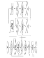
- FIG. 2 is a flowchart showing a control operation of the engine start control device according to the embodiment of the present invention.
- the engine start control device is mounted on a vehicle 1.
- the vehicle 1 includes an engine 11, a motor 12, an engine control unit (hereinafter referred to as ECU) 13, and a battery 14.
- the vehicle 1 is a so-called hybrid vehicle that is driven by a power source of at least one of the engine 11 and the motor 12.
- the vehicle 1 includes a crankshaft pulley 21 provided on the crankshaft 11 a of the engine 11, a motor pulley 22 provided on a rotor shaft (not shown) of the motor 12, a belt 23, and a transmission ( T / M) 24. Further, the vehicle 1 includes a differential gear 25 connected to the transmission 24, left and right drive shafts 26 connected to the differential gear 25, and left and right drive wheels 27.
- a mechanism for transmitting and shutting off the output of a clutch or the like is provided between the components of the engine 11, the motor 12, the transmission 24, the differential gear 25, the left and right drive shafts 26, and the left and right drive wheels 27.
- the output of the motor 12 is transmitted to the left and right drive wheels 27.
- the engine 11 is configured by, for example, a four-cycle engine that performs a series of four strokes including an intake stroke, a compression stroke, an expansion stroke, and an exhaust stroke.
- the engine 11 includes an intake manifold 11b.
- An intake passage for supplying intake air into the engine 11 is formed in the intake manifold 11b.
- the motor 12 is composed of a motor generator (MG) having both a function of an electric motor serving as a drive source for running the vehicle 1 and a function of a generator for charging the battery 14 by power generation.
- the motor 12 includes a rotor (not shown), a rotor shaft, and a stator, and is driven by electric power supplied from the battery 14.
- a belt 23 is wound around the motor pulley 22 and the crankshaft pulley 21 described above, and the power of the motor 12 is transmitted to the crankshaft 11a of the engine 11 by the motor pulley 22, the crankshaft pulley 21 and the belt 23. .
- the ECU 13 is constituted by a microcomputer.
- the microcomputer includes a CPU (Central Processing Unit), a RAM (Random Access Memory), a ROM (Read Only Memory), a flash memory, an input port, an output port, and a network module.
- the network module can communicate with another electronic control unit such as a transmission electronic control unit via a CAN (Controller Area Network).
- ECU13 performs arithmetic processing based on the data and program stored in ROM. For example, when the ECU 13 detects that the accelerator is turned off while the vehicle 1 is traveling, the ECU 13 executes fuel injection cut control for cutting the fuel injection to the engine 11, and the vehicle speed is reduced to idle. When the condition necessary for the stop is satisfied, the engine 11 is stopped idling.
- the ECU 13 supplies power from the battery 14 to generate power in the motor 12 while continuing fuel injection cut control triggered by the release of the brake during idling stop.
- the power generated by the motor 12 is transmitted to the crankshaft 11a via the motor pulley 22, the belt 23, and the crankshaft pulley 21, whereby the engine 11 is motored.
- the power transmitted to the crankshaft 11a is input to the transmission 24 and transmitted to the left and right drive wheels 27 via the differential gear 25 and the left and right drive shafts 26.
- the charge amount detection unit 13a includes sensors such as a current sensor (not shown) that detects a current flowing out or inflow from the battery 14 and a voltage sensor (not shown) that detects a terminal voltage of the battery 14. Based on the detection value detected by the sensor, the charge amount detection unit 13a determines the current charge state (SOC: State Of Charge) of the battery 14, the so-called current remaining capacity, as a detected charge amount (hereinafter referred to as a detected charge amount J). )).
- SOC State Of Charge
- the air amount detection unit 13b includes a sensor that detects an air amount, such as an air amount sensor provided in an intake passage of an intake pipe (not shown), and detects the air amount in the intake pipe.
- the start control unit 13c rotates the engine at the first rotation speed with the power output from the motor 12 on condition that the detected charge amount J detected by the charge amount detection unit 13a is equal to or greater than a predetermined first threshold value. Then, the engine 11 is started after the vehicle 1 travels.
- the start control unit 13c when the detected charge amount J satisfies a pattern A including a plurality of conditions including a condition that the detected charge amount J is equal to or greater than a predetermined first threshold, The engine 11 is started after performing a so-called EV creep running, which is a low-speed running when the accelerator is off, for a predetermined time tmax.
- the first threshold value is a minimum charge amount of the battery 14 that enables EV creep running, and is a preset value.
- the first engine speed is a minimum engine speed that enables EV creep running.
- the pattern A condition includes an A1 condition or an A6 condition described below.
- the A1 condition is that the air conditioner mounted on the vehicle 1 is OFF.
- the A2 condition is that the detected charge amount J is equal to or greater than the first threshold value.
- the A3 condition is that the temperature of the cooling water for cooling the engine 11 is equal to or higher than a predetermined threshold value.
- the A4 condition is that the temperature of ATF, which is the hydraulic oil of the transmission 24, is equal to or higher than a predetermined threshold value.
- the A5 condition is that the slope of the road surface on which the vehicle 1 is traveling is within a predetermined threshold.
- the A6 condition is that the electric load of the vehicle 1 is not more than a predetermined threshold value.
- Each of these predetermined threshold values is a value set in advance so as to meet each condition.
- the A1 condition and the A2 condition are for avoiding a situation in which EV creep running and start assist cannot be sufficiently performed assuming a load applied to the motor 12 when performing EV creep running of the vehicle 1 and starting assistance of the engine 11. Is set.
- the friction in the engine 11 or the transmission 24 is reduced, and the load on the motor 12 is reduced when performing EV creep running or start assist. It is set in consideration of.
- the A5 condition is that, when EV creep running is performed when the slope of the road surface is an uphill above a predetermined threshold, the load applied to the motor 12 increases more than usual, and there is a possibility that EV creep running and start assist cannot be performed. It is set to avoid being.
- the A6 condition is set to prevent excessive power consumption of the battery 14 and to prevent the battery 14 from being insufficiently charged or deteriorated. That is, when EV creep running or start assist is performed by the start control unit 13c when the electric load of the vehicle 1 is equal to or greater than a predetermined threshold, the load due to EV creep running or start assist is added to the battery in addition to the electric load. 14, the amount of charge of the battery 14 may be insufficient or deteriorate.
- the determination as to whether or not the electrical load is equal to or less than a predetermined threshold is performed by using, for example, a sensor such as a current sensor to calculate the power supplied from the battery 14 by the operation of each element connected to the battery 14 and supplied with power. Detection is performed by comparing the detected value with a reference value.
- the start control unit 13c outputs the power output from the motor 12 on condition that the detected charge amount J is less than the first threshold value and is equal to or greater than a predetermined second threshold value set lower than the first threshold value.
- the engine 11 is started after the rotational speed of the engine 11 is increased to a predetermined rotational speed.
- the second threshold value is a value that is set in advance, with the detected charge amount J serving as a reference for allowing the above-described start assist.
- the start control unit 13c sets a condition that the detected charge amount J is less than the first threshold and not less than a predetermined second threshold set lower than the first threshold, as will be described later.
- the start assist is executed by satisfying a pattern B condition including a plurality of conditions including the condition.
- the start assist performs motoring that raises the engine 11 to a second rotational speed that is about the engine idling rotational speed until the pressure in the intake manifold 11b of the engine 11 reaches a predetermined value.
- the engine 11 is started with the output power.
- the pressure in the intake manifold 11b is detected by a negative pressure sensor that detects the negative pressure in the intake manifold 11b.
- the start controller 13c Since the pressure in the intake manifold 11b and the air amount in the intake manifold 11b are in a proportional relationship, the start controller 13c replaces the pressure in the intake manifold 11b with the air amount detected by the air amount sensor. Thus, the start assist may be executed. That is, the start control unit 13c performs motoring to raise the engine 11 to a second rotational speed that is about the engine idling rotational speed until the air amount in the intake manifold 11b of the engine 11 reaches a predetermined value, and outputs from the motor 12 The engine 11 may be started with the motive power.
- the pattern B condition includes a B1 condition, an A3 condition, an A4 condition, an A5 condition, and an A6 condition.
- the B1 condition is that the detected charge amount J is equal to or greater than a predetermined threshold value that permits start assist.
- the pattern B condition does not include the A1 condition, which is one of the pattern A conditions.
- the operation amount of the air conditioner that is, the degree of cooling or heating becomes small, and the load applied to the battery 14 becomes relatively small. It is not necessary to include in the B condition.
- the start assist control based on the pattern B condition is performed while the operation amount of the air conditioner is small, it is not necessary to include the A1 condition in the pattern B condition.
- the start control unit 13c starts the engine 11 with the power output from the motor 12 on condition that the detected charge amount J is less than the second threshold value. Specifically, the start control unit 13c starts the engine 11 with the power output from the motor 12 when the pattern C condition, which is a condition in which the pattern A condition and the pattern B condition are not satisfied, and Restart fuel injection.
- the start control unit 13c starts the engine 11 with power output from the battery 14 on condition that the air amount in the intake pipe detected by the air amount detection unit 13b is less than a predetermined amount.
- the battery 14 is formed of a known secondary battery such as a lead storage battery or a lithium ion storage battery that supplies power to various electric loads of the vehicle 1 and elements such as the motor 12, and is sequentially charged and discharged.
- a known secondary battery such as a lead storage battery or a lithium ion storage battery that supplies power to various electric loads of the vehicle 1 and elements such as the motor 12, and is sequentially charged and discharged.
- the transmission 24 is composed of a transmission that shifts the power generated by the engine 11, and includes a plurality of planetary gear mechanisms (not shown) and a plurality of friction engagement elements that constitute clutches and brakes (not shown). Yes.
- the transmission 24 forms a desired gear stage by changing the gripping of each friction engagement element in accordance with hydraulic fluid supplied from a hydraulic control device (not shown), thereby determining the gear ratio of the transmission 24.
- the transmission 24 forms, for example, any one of six forward shift stages from 1st to 6th speed and one reverse shift stage.
- the power changed by the transmission 24 is transmitted to the differential gear 25.
- the differential gear 25 is connected to the left and right drive shafts 26, and the power input from the output shaft of the transmission 24 is transmitted from the left and right drive shafts 26 to the left and right drive wheels 27, respectively.
- the ECU 13 determines whether or not the engine 11 is performing idling stop control (step S11). If the ECU 13 determines that the engine 11 is not performing idling stop control, the ECU 13 ends the operation. When the ECU 13 determines that the engine 11 is performing idling stop control, the ECU 13 determines whether a brake (not shown) of the vehicle 1 is OFF (step S12).
- the ECU 13 determines that the brake is OFF in step S12, the ECU 13 acquires detection information such as the state of charge of the battery 14 detected by each sensor, the temperature level, and the magnitude of the electric load applied to the battery 14 (step S13). .
- the ECU 13 determines whether or not the pattern A condition is satisfied based on the acquired detection information (step S14). That is, the ECU 13 determines whether or not all of the A1 condition to the A6 condition are satisfied.
- the ECU 13 determines whether or not an accelerator (not shown) of the vehicle 1 is ON (step S22).
- step S17 the ECU 13 will restart the fuel injection of the engine 11, if it judges that the accelerator of the vehicle 1 is ON (step S17), and will complete
- step S23 the ECU 13 determines whether or not the engine 11 is requested to forcibly start the engine such as a start switch ON (step S23).
- the ECU 13 determines whether or not the duration t after starting the time count exceeds the maximum time tmax of EV creep travel (step S24).
- the ECU 13 determines that the duration t does not exceed the maximum time tmax, the ECU 13 returns to the determination of whether the accelerator of the vehicle 1 is ON (step S22).
- the ECU 13 determines that the duration t exceeds the maximum time tmax, the ECU 13 restarts the fuel injection of the engine 11 (step S17), starts the engine, and ends the operation.
- step S14 determines whether the pattern A condition is not satisfied. That is, the ECU 13 determines whether or not all of the B1 condition, the A3 condition, and the A6 condition are satisfied.
- the ECU 13 determines whether or not the accelerator of the vehicle 1 is ON (step S32).
- step S17 the ECU 13 will restart the fuel injection of the engine 11, if it judges that the accelerator of the vehicle 1 is ON (step S17), and will complete
- step S33 the ECU 13 determines whether there is a request for forced engine start such as a start switch ON for the engine 11 (step S33).
- step S17 the ECU 13 restarts fuel injection of the engine 11 (step S17), starts the engine, and ends the operation.
- the ECU 13 determines whether or not the pressure p in the intake manifold 11b of the engine 11 is equal to or lower than a pressure pth at which fuel injection is permitted (step S34). When the ECU 13 determines that the pressure p is not equal to or lower than the pressure pth, the ECU 13 determines again whether or not the accelerator of the vehicle 1 is ON (step S32). If ECU13 judges that the pressure p is below the pressure pth, it will restart the fuel injection of the engine 11 (step S17), will start an engine, and will complete
- step S15 when the ECU 13 determines that the pattern B condition is not satisfied, the ECU 13 starts driving the motor 12 and rotates the engine 11 (step S16). The ECU 13 resumes fuel injection immediately after the start of rotation of the engine 11 (step S17), starts the engine, and ends the operation.
- the engine start control device of the present embodiment includes a charge amount detection unit 13a and a start control unit 13c.
- the start control unit 13c has a large detected charge amount J, the EV creep travel is performed.
- the detected charge amount J is small, the engine 11 is started.
- the detected charge amount J is medium, the engine 11 is started after motoring.
- the start control is executed based on detailed conditions corresponding to the detected charge amount J, the power of the battery 14 is more efficiently utilized, and further, the battery 14 is prevented from deteriorating. The durability of the battery 14 is further improved.
- the air conditioner mounted on the vehicle 1 is OFF (A1 condition) and the detected charge amount J permits EV creep running.
- the condition is that it is equal to or greater than a predetermined threshold value (A2 condition).
- the engine start control device of the present embodiment can avoid the case where the EV creep running cannot be performed sufficiently, and can ensure the detected charge amount J and perform the EV creep running. Therefore, the power of the battery 14 is utilized more efficiently, the deterioration of the battery 14 is prevented, and the durability of the battery 14 is further improved.
- the temperature of the cooling water for cooling the engine 11 is equal to or higher than a predetermined threshold (A3 condition), and the ATF temperature of the transmission 24 is a predetermined threshold. This is the condition (A4 condition).
- the engine start control device of the present embodiment can perform EV creep travel without burden on the battery 14.
- the battery 14 can be prevented from deteriorating and the durability of the battery 14 can be further improved.
- the engine start control device of the present embodiment is based on the condition that the gradient of the road surface on which the vehicle 1 is traveling is within a predetermined threshold (A5 condition) in the pattern A condition, the EV creep travel is performed. The inability to do so is avoided.
- the engine start control device of the present embodiment can continue the EV creep running by satisfying the A5 condition.
- the engine start control device of the present embodiment is based on the condition that the electric load of the vehicle 1 is not more than a predetermined threshold (A6 condition) in the pattern A condition.
- a predetermined threshold A6 condition
- the start control by the start control unit 13c is avoided, and excessive power consumption is prevented, and the amount of charge of the battery 14 is prevented from being insufficient or deteriorated.
- the engine start control device of the present embodiment controls the rotation speed of the engine 11 with the power output from the motor 12 until the pressure in the intake manifold 11b of the engine 11 reaches a predetermined value. After motoring to increase the engine speed to a predetermined number of revolutions, start assist control of the engine 11 is executed.
- the engine start control device of the present embodiment can suppress the generation amount of output torque at the time of engine start and suppress vibration at the time of engine start.
- the engine start control device of the present embodiment includes the B1 condition and the A3 or A6 condition in the pattern B condition, so that the start assist can be performed reliably and the power of the battery 14 is utilized more efficiently.
- the durability of the battery 14 can be further improved by preventing the battery 14 from deteriorating.
- the engine start control device of the present embodiment avoids excessive EV creep travel and start assist when the detected charge amount J is small.
- the engine 11 can be started with the power output from the engine 14. As a result, excessive consumption of the battery 14 can be avoided, the battery 14 can be prevented from deteriorating, and the durability of the battery 14 can be further improved.
- the engine start control device of the present embodiment starts the engine 11 with the power output from the battery 14 on condition that the air amount in the intake pipe detected by the air amount detection unit 13b is less than a predetermined amount. As a result, vibration of the engine 11 can be further reduced when the engine 11 is started.
- the engine start control device can suppress the power consumption particularly when the power of the battery 14 is not sufficient, so that the frequency of idling stop can be ensured, and consequently the fuel consumption of the engine 11 can be ensured. Can be improved.
Landscapes
- Engineering & Computer Science (AREA)
- Mechanical Engineering (AREA)
- Chemical & Material Sciences (AREA)
- Combustion & Propulsion (AREA)
- Transportation (AREA)
- Automation & Control Theory (AREA)
- General Engineering & Computer Science (AREA)
- Hybrid Electric Vehicles (AREA)
- Electric Propulsion And Braking For Vehicles (AREA)
- Control Of Vehicle Engines Or Engines For Specific Uses (AREA)
Abstract
A start control unit (13c) starts an engine (11) after causing a vehicle (1) to travel by increasing an engine rotational speed to a first rotational speed by the output of a motor (12) on condition that a detected charge amount (J) detected by a charge amount detection unit (13a) is not smaller than a first threshold value, while starting the engine (11) after increasing the engine (11) rotational speed to a second rotational speed by the output of the motor (12) on condition that the detected charge amount (J) is smaller than the first threshold value and not smaller than a second threshold value set lower than the first threshold value.
Description
本発明は、エンジンの始動制御装置に関し、特に、バッテリから供給される電力で駆動するモータによりエンジンを始動させるエンジンの始動制御装置に関する。
The present invention relates to an engine start control device, and more particularly to an engine start control device that starts an engine by a motor driven by electric power supplied from a battery.
従来、車両を走行させる駆動源となるモータとして、電動機と発電機の機能を併せ持つモータジェネレータ(以下、モータという。)を用いるものが知られている。
Conventionally, a motor using a motor generator (hereinafter referred to as a motor) having both functions of an electric motor and a generator is known as a motor serving as a drive source for running the vehicle.
例えば、特許第3447937号(特許文献1)には、バッテリの充電量に応じて、モータで車両を走行させるか、エンジンで車両を走行させるかを切り替えることが可能なものが提案されている。
For example, Japanese Patent No. 3447937 (Patent Document 1) proposes a switch capable of switching between running a vehicle with a motor or running a vehicle with an engine according to the amount of charge of a battery.
特許第3447937号に提案されたものは、バッテリの充電量が所定量以上のときは、モータから出力される比較的に大きな動力で車両を発進させて走行させる一方、バッテリの充電量が所定量未満のときは、モータから出力される比較的に小さな動力でエンジンを始動させ、エンジンから出力される動力により車両を発進させて走行させるようにしている。
Japanese Patent No. 3447937 proposes that when the charge amount of the battery is greater than or equal to a predetermined amount, the vehicle is started and driven with relatively large power output from the motor, while the charge amount of the battery is predetermined amount. When the value is less than 1, the engine is started with relatively small power output from the motor, and the vehicle is started to run with the power output from the engine.
しかしながら、このような特許第3447937号に提案されたものにおいては、モータによる車両の走行からエンジンによる車両の走行に切り替える制御を、バッテリの充電量の所定量を基準にしているので、バッテリの充電量が所定量未満のときは、全てエンジンによる車両の走行に切り替えられてしまう。所定量が多めに設定されると、所定量を下回った場合に、なおモータによる車両の走行が可能なときでも、エンジンによる車両の走行に切り替えられてしまい、バッテリの電力が効率よく活用されないことがあるという問題がある。
However, in the one proposed in Japanese Patent No. 3447937, since the control for switching from the vehicle running by the motor to the vehicle running by the engine is based on a predetermined amount of charge of the battery, charging of the battery When the amount is less than the predetermined amount, all are switched to the running of the vehicle by the engine. If the predetermined amount is set to a large value, even if the vehicle can be driven by the motor when the amount is below the predetermined amount, the vehicle is switched to driving by the engine, and the battery power cannot be used efficiently. There is a problem that there is.
本発明は、上記のような問題を解決するためになされたものであり、バッテリの電力を効率的に活用することができるエンジンの始動制御装置を提供することを課題とする。
The present invention has been made to solve the above-described problems, and an object of the present invention is to provide an engine start control device that can efficiently use battery power.
上記課題を解決するための、本発明の第1の態様は、エンジンを出力により回転させるモータと、モータに電力を供給するバッテリと、バッテリの充電量を検出する充電量検出部と、エンジンの始動を制御する始動制御部と、を備えるエンジンの始動制御装置であって、始動制御部は、充電量検出部により検出された検出充電量が、第1閾値以上であることを条件として、モータの出力で前記エンジンの回転数を第1回転数まで上昇させて車両を走行させた後にエンジンを始動させ、検出充電量が、第1閾値未満であり、かつ第1閾値よりも低く設定された第2閾値以上であることを条件として、モータの出力でエンジンの回転数を第2回転数まで上昇させた後にエンジンを始動させるものから構成されている。
本発明の第2の態様としては、始動制御部は、検出充電量が、第2閾値未満であることを条件として、モータの出力直後にエンジンを始動させるものでもよい。 In order to solve the above problems, a first aspect of the present invention includes a motor that rotates an engine by output, a battery that supplies electric power to the motor, a charge amount detection unit that detects a charge amount of the battery, An engine start control device comprising: a start control unit that controls start, wherein the start control unit is configured to provide a motor on condition that the detected charge amount detected by the charge amount detection unit is equal to or greater than a first threshold value. With the output of the engine, the engine speed is increased to the first speed and the vehicle is started, and then the engine is started. The detected charge amount is set to be lower than the first threshold and lower than the first threshold. On the condition that it is equal to or greater than the second threshold, the engine is started after the engine speed is increased to the second speed by the output of the motor.
As a second aspect of the present invention, the start control unit may start the engine immediately after the output of the motor on condition that the detected charge amount is less than the second threshold value.
本発明の第3の態様としては、エンジンに供給する吸気を流通させる吸気管内の空気量を検出する空気量検出部を備え、始動制御部が、検出充電量が、第1閾値未満であり、かつ第1閾値よりも低く設定された第2閾値以上であることを条件として、モータの出力でエンジンを回転した後、空気量検出部により検出された空気量が所定量より少ないときに、エンジンを始動させるものでもよい。
A third aspect of the present invention includes an air amount detection unit that detects an air amount in an intake pipe that circulates intake air supplied to the engine, and the start control unit has a detected charge amount that is less than a first threshold value, When the air amount detected by the air amount detection unit is less than a predetermined amount after the engine is rotated by the output of the motor on the condition that it is equal to or higher than the second threshold value set lower than the first threshold value, the engine It is also possible to start.
上記の第1の態様によれば、始動制御部は、検出充電量が第1閾値以上であることを条件に、いわゆるEVクリープ走行を実行させた後にエンジンを始動させ、検出充電量が第1閾値未満であり、かつ第2閾値以上であることを条件に、いわゆるモータリングを行ってからエンジンを始動させ、さらに、検出充電量が第2閾値未満であることを条件に、エンジンを始動させている。したがって、始動制御部による始動制御が、検出充電量に応じたきめ細かな条件に基づいて実行されることになり、バッテリの電力が効率的に活用される。
上記の第2の態様によれば、始動制御部は、検出充電量が第2閾値未満であることを条件に、モータの出力直後にエンジンを始動させている。したがって、始動制御部による始動制御が、検出充電量に応じたきめ細かな条件に基づいて実行されることになり、バッテリの電力が効率的に活用される。 According to the first aspect, the start control unit starts the engine after performing the so-called EV creep running on the condition that the detected charge amount is equal to or greater than the first threshold, and the detected charge amount is the first charge amount. The engine is started after so-called motoring on the condition that it is less than the threshold and greater than or equal to the second threshold, and the engine is started on the condition that the detected charge amount is less than the second threshold. ing. Therefore, the start control by the start control unit is executed based on detailed conditions corresponding to the detected charge amount, and the power of the battery is efficiently utilized.
According to the second aspect, the start control unit starts the engine immediately after the output of the motor on the condition that the detected charge amount is less than the second threshold value. Therefore, the start control by the start control unit is executed based on detailed conditions corresponding to the detected charge amount, and the power of the battery is efficiently utilized.
上記の第3の態様によれば、始動制御部は、検出充電量が、第1閾値未満であり、かつ第1閾値よりも低く設定された第2閾値以上であることを条件として、モータの出力でエンジンを回転した後、空気量検出部により検出された吸気管内の空気量が所定量より少ないときに、エンジンを始動させるようにしているので、エンジンを始動するときに生じる振動を低減することができる。
According to the third aspect described above, the start control unit is configured such that the detected charge amount is less than the first threshold value and is equal to or greater than the second threshold value set lower than the first threshold value. After the engine is rotated with the output, the engine is started when the amount of air in the intake pipe detected by the air amount detection unit is less than a predetermined amount, so that vibration generated when the engine is started is reduced. be able to.
以下、本発明の実施形態に係るエンジンの始動制御装置について、図面を参照して説明する。
Hereinafter, an engine start control device according to an embodiment of the present invention will be described with reference to the drawings.
まず、構成を説明する。
本実施形態に係るエンジンの始動制御装置は、車両1に搭載されている。車両1は、図1に示すように、エンジン11と、モータ12と、エンジン制御ユニット(Engine Control Unit、以下、ECUという。)13と、バッテリ14とを備えている。車両1は、エンジン11およびモータ12の少なくともいずれかの動力源で駆動される、いわゆるハイブリッド車で構成されている。 First, the configuration will be described.
The engine start control device according to this embodiment is mounted on a vehicle 1. As shown in FIG. 1, the vehicle 1 includes anengine 11, a motor 12, an engine control unit (hereinafter referred to as ECU) 13, and a battery 14. The vehicle 1 is a so-called hybrid vehicle that is driven by a power source of at least one of the engine 11 and the motor 12.
本実施形態に係るエンジンの始動制御装置は、車両1に搭載されている。車両1は、図1に示すように、エンジン11と、モータ12と、エンジン制御ユニット(Engine Control Unit、以下、ECUという。)13と、バッテリ14とを備えている。車両1は、エンジン11およびモータ12の少なくともいずれかの動力源で駆動される、いわゆるハイブリッド車で構成されている。 First, the configuration will be described.
The engine start control device according to this embodiment is mounted on a vehicle 1. As shown in FIG. 1, the vehicle 1 includes an
また、車両1は、エンジン11のクランク軸11aに設けられたクランク軸プーリ21と、モータ12の図示しない回転子軸に設けられたモータプーリ22と、ベルト23と、エンジン11に連結されたトランスミッション(T/M)24とを備えている。さらに、車両1は、トランスミッション24に連結されたディファレンシャルギア25と、ディファレンシャルギア25に連結された左右のドライブシャフト26と、左右の駆動輪27とを備えている。
Further, the vehicle 1 includes a crankshaft pulley 21 provided on the crankshaft 11 a of the engine 11, a motor pulley 22 provided on a rotor shaft (not shown) of the motor 12, a belt 23, and a transmission ( T / M) 24. Further, the vehicle 1 includes a differential gear 25 connected to the transmission 24, left and right drive shafts 26 connected to the differential gear 25, and left and right drive wheels 27.
本実施形態において、エンジン11、モータ12、トランスミッション24、ディファレンシャルギア25、左右のドライブシャフト26および左右の駆動輪27の各構成の間にはクラッチなどの出力を伝達および遮断するための機構は備えておらず、モータ12が駆動されると、モータ12の出力が、左右の駆動輪27に伝達される。
In the present embodiment, a mechanism for transmitting and shutting off the output of a clutch or the like is provided between the components of the engine 11, the motor 12, the transmission 24, the differential gear 25, the left and right drive shafts 26, and the left and right drive wheels 27. However, when the motor 12 is driven, the output of the motor 12 is transmitted to the left and right drive wheels 27.
エンジン11は、例えば、吸気行程、圧縮行程、膨張行程および排気行程からなる一連の4行程を行う4サイクルエンジンによって構成されている。エンジン11は、インテークマニホールド11bを備えている。インテークマニホールド11bには、吸入空気をエンジン11内に供給する吸気通路が形成されている。
The engine 11 is configured by, for example, a four-cycle engine that performs a series of four strokes including an intake stroke, a compression stroke, an expansion stroke, and an exhaust stroke. The engine 11 includes an intake manifold 11b. An intake passage for supplying intake air into the engine 11 is formed in the intake manifold 11b.
モータ12は、車両1を走行させる駆動源となる電動機の機能と、発電によりバッテリ14を充電する発電機の機能とを併せ持つモータジェネレータ(MG)で構成されている。モータ12は、図示しない回転子と、回転子軸と、固定子とを有しており、バッテリ14から供給される電力で駆動されるようになっている。
The motor 12 is composed of a motor generator (MG) having both a function of an electric motor serving as a drive source for running the vehicle 1 and a function of a generator for charging the battery 14 by power generation. The motor 12 includes a rotor (not shown), a rotor shaft, and a stator, and is driven by electric power supplied from the battery 14.
前述のモータプーリ22と、クランク軸プーリ21とには、ベルト23が巻き掛けられており、モータ12の動力は、モータプーリ22、クランク軸プーリ21およびベルト23によりエンジン11のクランク軸11aに伝達される。
A belt 23 is wound around the motor pulley 22 and the crankshaft pulley 21 described above, and the power of the motor 12 is transmitted to the crankshaft 11a of the engine 11 by the motor pulley 22, the crankshaft pulley 21 and the belt 23. .
ECU13は、マイクロコンピュータによって構成されている。マイクロコンピュータは、CPU(Central Processing Unit)と、RAM(Random Access Memory)と、ROM(Read Only Memory)と、フラッシュメモリと、入力ポートと、出力ポートと、ネットワークモジュールとを備えている。なお、ネットワークモジュールは、トランスミッション電子制御ユニットなどの他の電子制御ユニットとCAN(Controller Area Network)を介して通信を行うことができるようになっている。
The ECU 13 is constituted by a microcomputer. The microcomputer includes a CPU (Central Processing Unit), a RAM (Random Access Memory), a ROM (Read Only Memory), a flash memory, an input port, an output port, and a network module. The network module can communicate with another electronic control unit such as a transmission electronic control unit via a CAN (Controller Area Network).
ECU13は、ROM内に格納されたデータやプログラムに基づいて演算処理を実行する。ECU13は、例えば、車両1の走行中にアクセルがOFFの状態になったことを検出すると、エンジン11に対して、燃料の噴射をカットする燃料噴射カット制御を実行し、車速が低下してアイドリングストップに必要な条件が成立すると、エンジン11をアイドリングストップさせる。
ECU13 performs arithmetic processing based on the data and program stored in ROM. For example, when the ECU 13 detects that the accelerator is turned off while the vehicle 1 is traveling, the ECU 13 executes fuel injection cut control for cutting the fuel injection to the engine 11, and the vehicle speed is reduced to idle. When the condition necessary for the stop is satisfied, the engine 11 is stopped idling.
ECU13は、アイドリングストップ中に、ブレーキが解除されたことをトリガとして燃料噴射カット制御を継続したままで、バッテリ14から電力を供給してモータ12に動力を発生させる。モータ12によって発生する動力は、モータプーリ22、ベルト23およびクランク軸プーリ21を介してクランク軸11aに伝達されることにより、エンジン11がモータリングされる。
The ECU 13 supplies power from the battery 14 to generate power in the motor 12 while continuing fuel injection cut control triggered by the release of the brake during idling stop. The power generated by the motor 12 is transmitted to the crankshaft 11a via the motor pulley 22, the belt 23, and the crankshaft pulley 21, whereby the engine 11 is motored.
クランク軸11aに伝達された動力は、トランスミッション24に入力され、ディファレンシャルギア25、左右のドライブシャフト26を介して左右の駆動輪27に伝達される。
The power transmitted to the crankshaft 11a is input to the transmission 24 and transmitted to the left and right drive wheels 27 via the differential gear 25 and the left and right drive shafts 26.
充電量検出部13aは、バッテリ14から流出または流入する電流を検出する図示しない電流センサや、バッテリ14の端子電圧を検出する図示しない電圧センサなどのセンサにより構成されている。充電量検出部13aは、センサにより検出された検出値に基づいて、バッテリ14の現在の充電状態(SOC:State Of Charge)、いわゆる現在の残容量を検出充電量(以下。検出充電量Jという。)として検出する。
The charge amount detection unit 13a includes sensors such as a current sensor (not shown) that detects a current flowing out or inflow from the battery 14 and a voltage sensor (not shown) that detects a terminal voltage of the battery 14. Based on the detection value detected by the sensor, the charge amount detection unit 13a determines the current charge state (SOC: State Of Charge) of the battery 14, the so-called current remaining capacity, as a detected charge amount (hereinafter referred to as a detected charge amount J). )).
空気量検出部13bは、図示しない吸気管の吸気通路内に設けられた空気量センサなどの空気量を検出するセンサからなり、吸気管内の空気量を検出するようになっている。
The air amount detection unit 13b includes a sensor that detects an air amount, such as an air amount sensor provided in an intake passage of an intake pipe (not shown), and detects the air amount in the intake pipe.
始動制御部13cは、充電量検出部13aにより検出された検出充電量Jが、所定の第1閾値以上であることを条件として、モータ12から出力される動力でエンジンを第1回転数で回転させて車両1を走行させた後にエンジン11を始動させる。
本実施形態において、始動制御部13cは、検出充電量Jが、以下に説明するように、所定の第1閾値以上であることの条件を含む複数の条件からなるパターンA条件を満たすと、車両1をアクセルオフ時での低速走行となる、いわゆるEVクリープ走行を所定時間のtmax間だけ行ってからエンジン11を始動させるようになっている。 Thestart control unit 13c rotates the engine at the first rotation speed with the power output from the motor 12 on condition that the detected charge amount J detected by the charge amount detection unit 13a is equal to or greater than a predetermined first threshold value. Then, the engine 11 is started after the vehicle 1 travels.
In the present embodiment, thestart control unit 13c, when the detected charge amount J satisfies a pattern A including a plurality of conditions including a condition that the detected charge amount J is equal to or greater than a predetermined first threshold, The engine 11 is started after performing a so-called EV creep running, which is a low-speed running when the accelerator is off, for a predetermined time tmax.
本実施形態において、始動制御部13cは、検出充電量Jが、以下に説明するように、所定の第1閾値以上であることの条件を含む複数の条件からなるパターンA条件を満たすと、車両1をアクセルオフ時での低速走行となる、いわゆるEVクリープ走行を所定時間のtmax間だけ行ってからエンジン11を始動させるようになっている。 The
In the present embodiment, the
第1閾値は、EVクリープ走行を可能とする最低限度のバッテリ14の充電量であり、予め設定された値である。エンジンの第1回転数は、EVクリープ走行を可能とする最低限度のエンジンの回転数である。
The first threshold value is a minimum charge amount of the battery 14 that enables EV creep running, and is a preset value. The first engine speed is a minimum engine speed that enables EV creep running.
パターンA条件は、具体的には、以下に説明するA1条件ないしA6条件を含んでいる。
A1条件は、車両1に搭載されたエアコンがOFFとなっていることである。A2条件は、検出充電量Jが、第1閾値以上となっていることである。A3条件は、エンジン11を冷却する冷却水の温度が所定の閾値以上となっていることである。A4条件は、トランスミッション24の作動油であるATFの温度が所定の閾値以上となっていることである。 Specifically, the pattern A condition includes an A1 condition or an A6 condition described below.
The A1 condition is that the air conditioner mounted on the vehicle 1 is OFF. The A2 condition is that the detected charge amount J is equal to or greater than the first threshold value. The A3 condition is that the temperature of the cooling water for cooling theengine 11 is equal to or higher than a predetermined threshold value. The A4 condition is that the temperature of ATF, which is the hydraulic oil of the transmission 24, is equal to or higher than a predetermined threshold value.
A1条件は、車両1に搭載されたエアコンがOFFとなっていることである。A2条件は、検出充電量Jが、第1閾値以上となっていることである。A3条件は、エンジン11を冷却する冷却水の温度が所定の閾値以上となっていることである。A4条件は、トランスミッション24の作動油であるATFの温度が所定の閾値以上となっていることである。 Specifically, the pattern A condition includes an A1 condition or an A6 condition described below.
The A1 condition is that the air conditioner mounted on the vehicle 1 is OFF. The A2 condition is that the detected charge amount J is equal to or greater than the first threshold value. The A3 condition is that the temperature of the cooling water for cooling the
さらに、A5条件は、車両1が走行している路面の勾配が所定の閾値以内となっていることである。A6条件は、車両1の電気負荷が所定の閾値以下となっていることである。これらの各所定の閾値は各条件に適合するように予め設定された値となっている。
Furthermore, the A5 condition is that the slope of the road surface on which the vehicle 1 is traveling is within a predetermined threshold. The A6 condition is that the electric load of the vehicle 1 is not more than a predetermined threshold value. Each of these predetermined threshold values is a value set in advance so as to meet each condition.
A1条件およびA2条件は、車両1のEVクリープ走行やエンジン11の始動アシストを行う際にモータ12にかかる負荷を想定して、EVクリープ走行や始動アシストが十分に行えなくなることを回避するために設定されている。
The A1 condition and the A2 condition are for avoiding a situation in which EV creep running and start assist cannot be sufficiently performed assuming a load applied to the motor 12 when performing EV creep running of the vehicle 1 and starting assistance of the engine 11. Is set.
A3条件およびA4条件は、冷却水やATFの温度が高ければ、エンジン11内やトランスミッション24内における摩擦が低減され、EVクリープ走行や始動アシストを行う際にモータ12にかかる負荷が低減されることを考慮して設定されている。
As for the A3 condition and the A4 condition, if the temperature of the cooling water or the ATF is high, the friction in the engine 11 or the transmission 24 is reduced, and the load on the motor 12 is reduced when performing EV creep running or start assist. It is set in consideration of.
A5条件は、路面の勾配が所定の閾値以上の上り坂である場合に、EVクリープ走行を行うと、モータ12にかかる負荷が通常よりも増大し、EVクリープ走行や始動アシストが行えなくなるおそれがあるのを回避するために設定されている。
The A5 condition is that, when EV creep running is performed when the slope of the road surface is an uphill above a predetermined threshold, the load applied to the motor 12 increases more than usual, and there is a possibility that EV creep running and start assist cannot be performed. It is set to avoid being.
また、A6条件は、バッテリ14の過大な電力の消費を防止し、バッテリ14の充電量が不足することや劣化することを防ぐために設定されている。すなわち、車両1の電気負荷が所定の閾値以上となっているときに、始動制御部13cによりEVクリープ走行や始動アシストが行われると、電気負荷に加えてEVクリープ走行や始動アシスによる負荷がバッテリ14にかかるので、バッテリ14の充電量が不足したり、劣化することがある。
The A6 condition is set to prevent excessive power consumption of the battery 14 and to prevent the battery 14 from being insufficiently charged or deteriorated. That is, when EV creep running or start assist is performed by the start control unit 13c when the electric load of the vehicle 1 is equal to or greater than a predetermined threshold, the load due to EV creep running or start assist is added to the battery in addition to the electric load. 14, the amount of charge of the battery 14 may be insufficient or deteriorate.
電気負荷が所定の閾値以下であるか否かの判断は、バッテリ14に接続されていて電力が供給される各要素の稼働によってバッテリ14から供給される電力を、例えば、電流センサなどのセンサで検出し、検出値と基準値との比較により行われる。
The determination as to whether or not the electrical load is equal to or less than a predetermined threshold is performed by using, for example, a sensor such as a current sensor to calculate the power supplied from the battery 14 by the operation of each element connected to the battery 14 and supplied with power. Detection is performed by comparing the detected value with a reference value.
また、始動制御部13cは、検出充電量Jが第1閾値未満であり、かつ第1閾値よりも低く設定された所定の第2閾値以上であることを条件として、モータ12から出力される動力でエンジン11の回転数を所定回転数まで上昇させた後にエンジン11を始動させるようになっている。
In addition, the start control unit 13c outputs the power output from the motor 12 on condition that the detected charge amount J is less than the first threshold value and is equal to or greater than a predetermined second threshold value set lower than the first threshold value. Thus, the engine 11 is started after the rotational speed of the engine 11 is increased to a predetermined rotational speed.
第2閾値は、検出充電量Jが前述の始動アシストが許可される基準となる値で、予め設定された値である。本実施形態において、始動制御部13cは、後述するように、検出充電量Jが第1閾値未満であり、かつ第1閾値よりも低く設定された所定の第2閾値以上であることの条件を含む複数の条件からなるパターンB条件を満たすことで、始動アシストを実行する。
The second threshold value is a value that is set in advance, with the detected charge amount J serving as a reference for allowing the above-described start assist. In the present embodiment, the start control unit 13c sets a condition that the detected charge amount J is less than the first threshold and not less than a predetermined second threshold set lower than the first threshold, as will be described later. The start assist is executed by satisfying a pattern B condition including a plurality of conditions including the condition.
始動アシストは、具体的には、エンジン11のインテークマニホールド11b内の圧力が所定の値になるまで、エンジン11をエンジンアイドリング回転数程度の第2回転数まで上昇させるモータリングを行い、モータ12から出力される動力でエンジン11を始動させることである。
Specifically, the start assist performs motoring that raises the engine 11 to a second rotational speed that is about the engine idling rotational speed until the pressure in the intake manifold 11b of the engine 11 reaches a predetermined value. The engine 11 is started with the output power.
インテークマニホールド11b内の圧力は、インテークマニホールド11b内の負圧を検出する負圧センサにより検出される。
The pressure in the intake manifold 11b is detected by a negative pressure sensor that detects the negative pressure in the intake manifold 11b.
インテークマニホールド11b内の圧力と、インテークマニホールド11b内の空気量とは、比例関係にあるので、始動制御部13cは、インテークマニホールド11b内の圧力に替えて、空気量センサが検出した空気量に基づいて、始動アシストを実行するようにしてもよい。すなわち、始動制御部13cは、エンジン11のインテークマニホールド11b内の空気量が所定の値になるまでエンジン11をエンジンアイドリング回転数程度の第2回転数まで上昇させるモータリングを行い、モータ12から出力される動力でエンジン11を始動させるようにしてもよい。
Since the pressure in the intake manifold 11b and the air amount in the intake manifold 11b are in a proportional relationship, the start controller 13c replaces the pressure in the intake manifold 11b with the air amount detected by the air amount sensor. Thus, the start assist may be executed. That is, the start control unit 13c performs motoring to raise the engine 11 to a second rotational speed that is about the engine idling rotational speed until the air amount in the intake manifold 11b of the engine 11 reaches a predetermined value, and outputs from the motor 12 The engine 11 may be started with the motive power.
パターンB条件は、具体的には、B1条件、A3条件、A4条件、A5条件およびA6条件を含んでいる。B1条件は、検出充電量Jが始動アシストを許可する所定の閾値以上となっていることである。
Specifically, the pattern B condition includes a B1 condition, an A3 condition, an A4 condition, an A5 condition, and an A6 condition. The B1 condition is that the detected charge amount J is equal to or greater than a predetermined threshold value that permits start assist.
パターンB条件には、パターンA条件の1つである、A1条件が含まれていない。所定条件が成立した場合にエンジンを停止させるアイドルストップの実行中においては、エアコンの動作量、すなわち冷房あるいは暖房の度合いが小さくなりバッテリ14に加わる負荷が比較的に小さくなるので、A1条件をパターンB条件に含める必要がない。また、パターンB条件による始動アシスト制御が、エアコンの動作量が小さい間に行われるので、A1条件をパターンB条件に含める必要がない。
The pattern B condition does not include the A1 condition, which is one of the pattern A conditions. During the execution of the idle stop that stops the engine when the predetermined condition is satisfied, the operation amount of the air conditioner, that is, the degree of cooling or heating becomes small, and the load applied to the battery 14 becomes relatively small. It is not necessary to include in the B condition. In addition, since the start assist control based on the pattern B condition is performed while the operation amount of the air conditioner is small, it is not necessary to include the A1 condition in the pattern B condition.
パターンB条件による始動アシスト制御中は、エアコンが作動していてもエアコンの動作量は低く抑えられており、パターンB条件による始動アシストの実行にあたって、モータ12への負荷は比較的に小さいので、パターンB条件にA1条件を含める必要がない。
During start assist control under the pattern B condition, even if the air conditioner is operating, the amount of operation of the air conditioner is kept low, and the load on the motor 12 is relatively small when executing the start assist according to the pattern B condition. It is not necessary to include the A1 condition in the pattern B condition.
始動制御部13cは、検出充電量Jが、第2閾値未満であることを条件として、モータ12から出力される動力でエンジン11を始動させる。具体的には、始動制御部13cは、パターンA条件およびパターンB条件が成立しない条件であるパターンC条件が成立すると、モータ12から出力される動力でエンジン11を始動させ、直後にシリンダへの燃料噴射を再開する。
The start control unit 13c starts the engine 11 with the power output from the motor 12 on condition that the detected charge amount J is less than the second threshold value. Specifically, the start control unit 13c starts the engine 11 with the power output from the motor 12 when the pattern C condition, which is a condition in which the pattern A condition and the pattern B condition are not satisfied, and Restart fuel injection.
始動制御部13cは、空気量検出部13bにより検出された吸気管内の空気量が所定量より少ないことを条件として、バッテリ14から出力される動力でエンジン11を始動させる。
The start control unit 13c starts the engine 11 with power output from the battery 14 on condition that the air amount in the intake pipe detected by the air amount detection unit 13b is less than a predetermined amount.
バッテリ14は、車両1の各種電機負荷やモータ12などの要素に電力を供給する鉛蓄電池やリチウムイオン蓄電池などの公知の二次電池で構成されており、逐次、充電や放電がなされる。
The battery 14 is formed of a known secondary battery such as a lead storage battery or a lithium ion storage battery that supplies power to various electric loads of the vehicle 1 and elements such as the motor 12, and is sequentially charged and discharged.
トランスミッション24は、エンジン11によって生成された動力を変速する変速機で構成されており、図示しない複数の遊星歯車機構と、図示しないクラッチやブレーキを構成する複数の摩擦係合要素とを有している。トランスミッション24は、図示しない油圧制御装置から供給される作動油に応じて、各摩擦係合要素の掴み変えを行うことにより、所望の変速段を形成することで、トランスミッション24の変速比が決定される。
The transmission 24 is composed of a transmission that shifts the power generated by the engine 11, and includes a plurality of planetary gear mechanisms (not shown) and a plurality of friction engagement elements that constitute clutches and brakes (not shown). Yes. The transmission 24 forms a desired gear stage by changing the gripping of each friction engagement element in accordance with hydraulic fluid supplied from a hydraulic control device (not shown), thereby determining the gear ratio of the transmission 24. The
トランスミッション24は、例えば、1速から6速の6つの前進変速段および1つの後進変速段のうちいずれかの変速段を形成するようになっている。トランスミッション24によって変速された動力は、ディファレンシャルギア25に伝達されるようになっている。
The transmission 24 forms, for example, any one of six forward shift stages from 1st to 6th speed and one reverse shift stage. The power changed by the transmission 24 is transmitted to the differential gear 25.
ディファレンシャルギア25は、左右のドライブシャフト26に連結されており、トランスミッション24の出力軸から入力された動力は、左右のドライブシャフト26から左右の駆動輪27にそれぞれ伝達されるようになっている。
The differential gear 25 is connected to the left and right drive shafts 26, and the power input from the output shaft of the transmission 24 is transmitted from the left and right drive shafts 26 to the left and right drive wheels 27, respectively.
次に、本実施形態のエンジンの始動制御装置におけるエンジン始動制御の動作について図2を参照して説明する。
Next, the operation of engine start control in the engine start control device of this embodiment will be described with reference to FIG.
まず、ECU13は、エンジン11がアイドリングストップの制御の実行中であるか否かを判断する(ステップS11)。ECU13は、エンジン11がアイドリングストップの制御の実行中でないと判断すると、動作を終了させる。ECU13は、エンジン11がアイドリングストップの制御の実行中であると判断すると、車両1の図示しないブレーキがOFFであるか否かを判断する(ステップS12)。
First, the ECU 13 determines whether or not the engine 11 is performing idling stop control (step S11). If the ECU 13 determines that the engine 11 is not performing idling stop control, the ECU 13 ends the operation. When the ECU 13 determines that the engine 11 is performing idling stop control, the ECU 13 determines whether a brake (not shown) of the vehicle 1 is OFF (step S12).
ECU13は、ステップS12でブレーキがOFFであると判断すると、各センサにより検出されたバッテリ14の充電状態や温度の高低、バッテリ14に加わる電気負荷の大小などの検出情報を取得する(ステップS13)。
When the ECU 13 determines that the brake is OFF in step S12, the ECU 13 acquires detection information such as the state of charge of the battery 14 detected by each sensor, the temperature level, and the magnitude of the electric load applied to the battery 14 (step S13). .
次いで、ECU13は、取得した検出情報に基づいて、パターンA条件が成立するか否かを判断する(ステップS14)。すなわち、ECU13は、A1条件ないしA6条件の全てが成立するか否かを判断する。
Next, the ECU 13 determines whether or not the pattern A condition is satisfied based on the acquired detection information (step S14). That is, the ECU 13 determines whether or not all of the A1 condition to the A6 condition are satisfied.
ECU13は、パターンA条件が成立したと判断すると、モータ12の駆動を開始しエンジン11を回転させるとともに時間カウントを開始する(ステップS21)。続いて、ECU13は、車両1の図示しないアクセルがONか否かを判断する(ステップS22)。
When the ECU 13 determines that the pattern A condition is satisfied, the ECU 13 starts driving the motor 12 to rotate the engine 11 and starts counting time (step S21). Subsequently, the ECU 13 determines whether or not an accelerator (not shown) of the vehicle 1 is ON (step S22).
ECU13は、車両1のアクセルがONであると判断すると、エンジン11の燃料噴射を再開し(ステップS17)、動作を終了する。ECU13は、車両1のアクセルがONでないと判断すると、エンジン11に対して始動スイッチONなどのエンジン強制始動が要求されているか否かを判断する(ステップS23)。
ECU13 will restart the fuel injection of the engine 11, if it judges that the accelerator of the vehicle 1 is ON (step S17), and will complete | finish operation | movement. When the ECU 13 determines that the accelerator of the vehicle 1 is not ON, the ECU 13 determines whether or not the engine 11 is requested to forcibly start the engine such as a start switch ON (step S23).
ECU13は、強制始動が要求されていると判断すると、エンジン11の燃料噴射を再開し(ステップS17)、エンジンを始動させ、動作を終了する。ECU13は、エンジン強制始動の要求がないと判断すると、時間カウントを開始してからの継続時間tが、EVクリープ走行の最大時間tmaxを超えているか否かを判断する(ステップS24)。
When the ECU 13 determines that the forced start is requested, the ECU 13 restarts the fuel injection of the engine 11 (step S17), starts the engine, and ends the operation. When determining that there is no request for forced engine start, the ECU 13 determines whether or not the duration t after starting the time count exceeds the maximum time tmax of EV creep travel (step S24).
ECU13は、継続時間tが、最大時間tmaxを超えていないと判断すると、車両1のアクセルがONか否かの判断(ステップS22)に戻る。ECU13は、継続時間tが、最大時間tmaxを超えていると判断すると、エンジン11の燃料噴射を再開し(ステップS17)、エンジンを始動させ、動作を終了する。
If the ECU 13 determines that the duration t does not exceed the maximum time tmax, the ECU 13 returns to the determination of whether the accelerator of the vehicle 1 is ON (step S22). When the ECU 13 determines that the duration t exceeds the maximum time tmax, the ECU 13 restarts the fuel injection of the engine 11 (step S17), starts the engine, and ends the operation.
ステップS14で、ECU13は、パターンA条件が成立しないと判断すると、パターンB条件が成立するか否かを判断する(ステップS15)。すなわち、ECU13は、B1条件、A3条件ないしA6条件の全てが成立するか否かを判断する。
If it is determined in step S14 that the pattern A condition is not satisfied, the ECU 13 determines whether the pattern B condition is satisfied (step S15). That is, the ECU 13 determines whether or not all of the B1 condition, the A3 condition, and the A6 condition are satisfied.
ECU13は、パターンB条件が成立したと判断すると、モータ12の駆動を開始しエンジン11を回転させる(ステップS31)。続いて、ECU13は、車両1のアクセルがONか否かを判断する(ステップS32)。
When the ECU 13 determines that the pattern B condition is satisfied, the ECU 13 starts driving the motor 12 and rotates the engine 11 (step S31). Subsequently, the ECU 13 determines whether or not the accelerator of the vehicle 1 is ON (step S32).
ECU13は、車両1のアクセルがONであると判断すると、エンジン11の燃料噴射を再開し(ステップS17)、動作を終了する。ECU13は、車両1のアクセルがONでないと判断すると、エンジン11に対して始動スイッチONなどのエンジン強制始動の要求があるか否かを判断する(ステップS33)。ECU13は、強制始動の要求があると判断すると、エンジン11の燃料噴射を再開し(ステップS17)、エンジンを始動させ、動作を終了する。
ECU13 will restart the fuel injection of the engine 11, if it judges that the accelerator of the vehicle 1 is ON (step S17), and will complete | finish operation | movement. When the ECU 13 determines that the accelerator of the vehicle 1 is not ON, the ECU 13 determines whether there is a request for forced engine start such as a start switch ON for the engine 11 (step S33). When the ECU 13 determines that there is a request for forced start, the ECU 13 restarts fuel injection of the engine 11 (step S17), starts the engine, and ends the operation.
ECU13は、エンジン強制始動の要求がないと判断すると、エンジン11のインテークマニホールド11b内の圧力pが、燃料噴射を許可できる圧力pth以下であるか否かを判断する(ステップS34)。ECU13は、圧力pが、圧力pth以下でないと判断すると、車両1のアクセルがONか否かを再度判断する(ステップS32)。ECU13は、圧力pが、圧力pth以下であると判断すると、エンジン11の燃料噴射を再開し(ステップS17)、エンジンを始動させ、動作を終了する。
When the ECU 13 determines that there is no request for forced engine start, the ECU 13 determines whether or not the pressure p in the intake manifold 11b of the engine 11 is equal to or lower than a pressure pth at which fuel injection is permitted (step S34). When the ECU 13 determines that the pressure p is not equal to or lower than the pressure pth, the ECU 13 determines again whether or not the accelerator of the vehicle 1 is ON (step S32). If ECU13 judges that the pressure p is below the pressure pth, it will restart the fuel injection of the engine 11 (step S17), will start an engine, and will complete | finish operation | movement.
ステップS15で、ECU13は、パターンB条件が成立しないと判断すると、モータ12の駆動を開始しエンジン11を回転させる(ステップS16)。ECU13は、エンジン11の回転開始の直後に燃料噴射を再開し(ステップS17)、エンジンを始動させ、動作を終了する。
In step S15, when the ECU 13 determines that the pattern B condition is not satisfied, the ECU 13 starts driving the motor 12 and rotates the engine 11 (step S16). The ECU 13 resumes fuel injection immediately after the start of rotation of the engine 11 (step S17), starts the engine, and ends the operation.
以下、本実施形態のエンジンの始動制御装置は、以上に説明したように構成されているので、次の効果が得られる。
すなわち、本実施形態のエンジンの始動制御装置は、充電量検出部13aと、始動制御部13cとを備えており、始動制御部13cが、検出充電量Jが多い場合には、EVクリープ走行を実行させ、検出充電量Jが少ない場合には、エンジン11を始動させ、さらに、検出充電量Jが中程度のときは、モータリングを行ってからエンジン11を始動させている。 Since the engine start control device of the present embodiment is configured as described above, the following effects can be obtained.
That is, the engine start control device of the present embodiment includes a charge amount detection unit 13a and astart control unit 13c. When the start control unit 13c has a large detected charge amount J, the EV creep travel is performed. When the detected charge amount J is small, the engine 11 is started. When the detected charge amount J is medium, the engine 11 is started after motoring.
すなわち、本実施形態のエンジンの始動制御装置は、充電量検出部13aと、始動制御部13cとを備えており、始動制御部13cが、検出充電量Jが多い場合には、EVクリープ走行を実行させ、検出充電量Jが少ない場合には、エンジン11を始動させ、さらに、検出充電量Jが中程度のときは、モータリングを行ってからエンジン11を始動させている。 Since the engine start control device of the present embodiment is configured as described above, the following effects can be obtained.
That is, the engine start control device of the present embodiment includes a charge amount detection unit 13a and a
その結果、検出充電量Jの多少に応じたきめ細かな条件に基づいて始動制御が実行されるので、バッテリ14の電力が、より効率的に活用され、さらに、バッテリ14が劣化することが防止され、バッテリ14の耐久性がより向上する。
As a result, since the start control is executed based on detailed conditions corresponding to the detected charge amount J, the power of the battery 14 is more efficiently utilized, and further, the battery 14 is prevented from deteriorating. The durability of the battery 14 is further improved.
具体的には、本実施形態のエンジンの始動制御装置は、パターンA条件において、車両1に搭載されたエアコンがOFFとなっていること(A1条件)および検出充電量JがEVクリープ走行を許可する所定の閾値以上であることいること(A2条件)を条件としている。
Specifically, in the engine start control device of the present embodiment, in the pattern A condition, the air conditioner mounted on the vehicle 1 is OFF (A1 condition) and the detected charge amount J permits EV creep running. The condition is that it is equal to or greater than a predetermined threshold value (A2 condition).
その結果、本実施形態のエンジンの始動制御装置は、これらEVクリープ走行が十分に行えない場合を回避することができ、検出充電量Jを確保してEVクリープ走行をさせることができる。したがって、バッテリ14の電力がより効率的に活用されるとともに、バッテリ14の劣化が防止され、バッテリ14の耐久性がより向上する。
As a result, the engine start control device of the present embodiment can avoid the case where the EV creep running cannot be performed sufficiently, and can ensure the detected charge amount J and perform the EV creep running. Therefore, the power of the battery 14 is utilized more efficiently, the deterioration of the battery 14 is prevented, and the durability of the battery 14 is further improved.
また、本実施形態のエンジンの始動制御装置は、パターンA条件において、エンジン11を冷却する冷却水の温度が所定の閾値以上であること(A3条件)およびトランスミッション24のATFの温度が所定の閾値以上であること(A4条件)を条件としている。
Further, in the engine start control device of the present embodiment, in the pattern A condition, the temperature of the cooling water for cooling the engine 11 is equal to or higher than a predetermined threshold (A3 condition), and the ATF temperature of the transmission 24 is a predetermined threshold. This is the condition (A4 condition).
その結果、エンジン11内やトランスミッション24内における摩擦が低減された状態で、EVクリープ走行が可能となるので、本実施形態のエンジンの始動制御装置は、バッテリ14に負担なくEVクリープ走行させることができ、バッテリ14の劣化を防止してバッテリ14の耐久性をより向上させることができる。
As a result, EV creep travel is possible in a state where friction in the engine 11 and the transmission 24 is reduced. Therefore, the engine start control device of the present embodiment can perform EV creep travel without burden on the battery 14. The battery 14 can be prevented from deteriorating and the durability of the battery 14 can be further improved.
また、本実施形態のエンジンの始動制御装置は、パターンA条件において、車両1が走行している路面の勾配が所定の閾値以内であること(A5条件)を条件としているので、EVクリープ走行が行えなくなることが回避される。
In addition, since the engine start control device of the present embodiment is based on the condition that the gradient of the road surface on which the vehicle 1 is traveling is within a predetermined threshold (A5 condition) in the pattern A condition, the EV creep travel is performed. The inability to do so is avoided.
すなわち、路面の勾配が所定の閾値以上の上り坂である場合に、EVクリープ走行を行うと、モータ12の負荷が通常よりも増大してしまうので、EVクリープ走行を行えなくなる。本実施形態のエンジンの始動制御装置は、A5条件を満たすことで、EVクリープ走行を継続させることができる。
That is, when the EV creep travel is performed when the road surface slope is an uphill with a predetermined threshold value or more, the load on the motor 12 increases more than usual, and thus the EV creep travel cannot be performed. The engine start control device of the present embodiment can continue the EV creep running by satisfying the A5 condition.
また、本実施形態のエンジンの始動制御装置は、パターンA条件において、車両1の電気負荷が所定の閾値以下であること(A6条件)を条件としているので、車両1の電気負荷が大きいときに、始動制御部13cによる始動制御が回避されて過大な電力の消費が防止され、バッテリ14の充電量が不足することや劣化することが防止される。
Further, the engine start control device of the present embodiment is based on the condition that the electric load of the vehicle 1 is not more than a predetermined threshold (A6 condition) in the pattern A condition. Thus, the start control by the start control unit 13c is avoided, and excessive power consumption is prevented, and the amount of charge of the battery 14 is prevented from being insufficient or deteriorated.
また、本実施形態のエンジンの始動制御装置は、パターンB条件が成立すると、エンジン11のインテークマニホールド11b内の圧力が所定の値になるまでモータ12から出力される動力でエンジン11の回転数を所定回転数まで上昇させるモータリングをした後にエンジン11の始動アシスト制御を実行する。
In addition, when the pattern B condition is satisfied, the engine start control device of the present embodiment controls the rotation speed of the engine 11 with the power output from the motor 12 until the pressure in the intake manifold 11b of the engine 11 reaches a predetermined value. After motoring to increase the engine speed to a predetermined number of revolutions, start assist control of the engine 11 is executed.
その結果、本実施形態のエンジンの始動制御装置は、エンジン始動時の出力トルクの発生量を抑え、エンジン始動時の振動を抑えることができる。
As a result, the engine start control device of the present embodiment can suppress the generation amount of output torque at the time of engine start and suppress vibration at the time of engine start.
本実施形態のエンジンの始動制御装置は、パターンB条件に、B1条件とA3条件ないしA6条件を含めているので、始動アシストを確実に行うことができ、バッテリ14の電力をより効率的に活用するとともに、バッテリ14が劣化することを防止してバッテリ14の耐久性をより向上させることができる。
The engine start control device of the present embodiment includes the B1 condition and the A3 or A6 condition in the pattern B condition, so that the start assist can be performed reliably and the power of the battery 14 is utilized more efficiently. In addition, the durability of the battery 14 can be further improved by preventing the battery 14 from deteriorating.
さらに、本実施形態のエンジンの始動制御装置は、検出充電量Jが、パターンC条件を条件としているので、検出充電量Jが少ないときに、無理なEVクリープ走行や始動アシストを回避し、バッテリ14から出力される動力でエンジン11を始動させることができる。その結果、バッテリ14の過大な消費を回避することができ、バッテリ14が劣化することを防止してバッテリ14の耐久性をより向上させることができる。
Further, since the detected charge amount J is based on the pattern C condition, the engine start control device of the present embodiment avoids excessive EV creep travel and start assist when the detected charge amount J is small. The engine 11 can be started with the power output from the engine 14. As a result, excessive consumption of the battery 14 can be avoided, the battery 14 can be prevented from deteriorating, and the durability of the battery 14 can be further improved.
また、本実施形態のエンジンの始動制御装置は、空気量検出部13bにより検出された吸気管内の空気量が所定量より少ないことを条件として、バッテリ14から出力される動力でエンジン11を始動させるようしているので、エンジン11の始動時に、エンジン11の振動をより低減させることができる。
In addition, the engine start control device of the present embodiment starts the engine 11 with the power output from the battery 14 on condition that the air amount in the intake pipe detected by the air amount detection unit 13b is less than a predetermined amount. As a result, vibration of the engine 11 can be further reduced when the engine 11 is started.
本実施形態のエンジンの始動制御装置は、特に、バッテリ14の電力に余裕がないときには、電力消費量を抑えることができるので、アイドリングストップの頻度を確保することができ、ひいては、エンジン11の燃費を向上させることができる。
The engine start control device according to the present embodiment can suppress the power consumption particularly when the power of the battery 14 is not sufficient, so that the frequency of idling stop can be ensured, and consequently the fuel consumption of the engine 11 can be ensured. Can be improved.
本発明の実施形態を開示したが、当業者によっては本発明の範囲を逸脱することなく変更が加えられうることは明白である。すべてのこのような修正および等価物が次の各請求項に含まれることが意図されている。
Although embodiments of the present invention have been disclosed, it will be apparent to those skilled in the art that changes may be made without departing from the scope of the present invention. All such modifications and equivalents are intended to be included in the following claims.
11 エンジン
12 モータ
13 ECU
13a 充電量検出部
13b 空気量検出部
13c 始動制御部
14 バッテリ
J 検出充電量 11Engine 12 Motor 13 ECU
13a Chargeamount detection unit 13b Air amount detection unit 13c Start control unit 14 Battery J Detected charge amount
12 モータ
13 ECU
13a 充電量検出部
13b 空気量検出部
13c 始動制御部
14 バッテリ
J 検出充電量 11
13a Charge
Claims (3)
- エンジンを出力により回転させるモータと、
前記モータに電力を供給するバッテリと、
前記バッテリの充電量を検出する充電量検出部と、
前記エンジンの始動を制御する始動制御部と、
を備えるエンジンの始動制御装置であって、
前記始動制御部は、前記充電量検出部により検出された検出充電量が、第1閾値以上であることを条件として、前記モータの出力で前記エンジンの回転数を第1回転数まで上昇させて車両を走行させた後に前記エンジンを始動させ、
前記検出充電量が、前記第1閾値未満であり、かつ前記第1閾値よりも低く設定された第2閾値以上であることを条件として、前記モータの出力で前記エンジンの回転数を第2回転数まで上昇させた後に前記エンジンを始動させることを特徴とするエンジンの始動制御装置。 A motor that rotates the engine by output;
A battery for supplying power to the motor;
A charge amount detection unit for detecting a charge amount of the battery;
A start control unit for controlling the start of the engine;
An engine start control device comprising:
The start control unit increases the engine speed to the first rotation speed by the output of the motor on the condition that the detected charge amount detected by the charge amount detection unit is not less than a first threshold value. Start the engine after running the vehicle,
On the condition that the detected charge amount is less than the first threshold value and is equal to or greater than a second threshold value set lower than the first threshold value, the engine speed is set to the second rotation by the output of the motor. An engine start control device, wherein the engine is started after being increased to a number. - 前記始動制御部は、前記検出充電量が、前記第2閾値未満であることを条件として、前記モータの出力直後に前記エンジンを始動させることを特徴とする請求項1に記載のエンジンの始動制御装置。 2. The engine start control according to claim 1, wherein the start control unit starts the engine immediately after the output of the motor on the condition that the detected charge amount is less than the second threshold value. apparatus.
- 前記エンジンに供給する吸気を流通させる吸気管内の空気量を検出する空気量検出部を備え、前記始動制御部は、前記検出充電量が、前記第1閾値未満であり、かつ前記第1閾値よりも低く設定された第2閾値以上であることを条件として、前記モータの出力で前記エンジンを回転した後、前記空気量検出部により検出された前記空気量が所定量より少ないときに、前記エンジンを始動させることを特徴とする請求項1に記載のエンジンの始動制御装置。 An air amount detection unit that detects an air amount in an intake pipe that distributes intake air supplied to the engine, wherein the start control unit is configured such that the detected charge amount is less than the first threshold value and is less than the first threshold value; If the air amount detected by the air amount detection unit is less than a predetermined amount after the engine is rotated by the output of the motor on the condition that it is equal to or higher than a second threshold value set to be lower, the engine The engine start control device according to claim 1, wherein the engine start control device is started.
Priority Applications (1)
| Application Number | Priority Date | Filing Date | Title |
|---|---|---|---|
| DE112015002022.5T DE112015002022B4 (en) | 2014-04-28 | 2015-04-17 | ENGINE STARTING CONTROL DEVICE |
Applications Claiming Priority (2)
| Application Number | Priority Date | Filing Date | Title |
|---|---|---|---|
| JP2014-092254 | 2014-04-28 | ||
| JP2014092254A JP6303774B2 (en) | 2014-04-28 | 2014-04-28 | Engine start control device |
Publications (1)
| Publication Number | Publication Date |
|---|---|
| WO2015166818A1 true WO2015166818A1 (en) | 2015-11-05 |
Family
ID=54358551
Family Applications (1)
| Application Number | Title | Priority Date | Filing Date |
|---|---|---|---|
| PCT/JP2015/061817 WO2015166818A1 (en) | 2014-04-28 | 2015-04-17 | Engine start control device |
Country Status (3)
| Country | Link |
|---|---|
| JP (1) | JP6303774B2 (en) |
| DE (1) | DE112015002022B4 (en) |
| WO (1) | WO2015166818A1 (en) |
Cited By (2)
| Publication number | Priority date | Publication date | Assignee | Title |
|---|---|---|---|---|
| CN110329238A (en) * | 2019-06-18 | 2019-10-15 | 浙江吉利控股集团有限公司 | A kind of engine start control method, device and equipment |
| CN110691724A (en) * | 2017-05-30 | 2020-01-14 | 株式会社电装 | Control device for hybrid vehicle |
Citations (5)
| Publication number | Priority date | Publication date | Assignee | Title |
|---|---|---|---|---|
| JP2000324608A (en) * | 1999-04-30 | 2000-11-24 | Unisia Jecs Corp | Controller for engine and generator motor |
| JP2003106194A (en) * | 2001-09-28 | 2003-04-09 | Hitachi Ltd | Internal combustion engine control system for vehicle |
| JP2006283722A (en) * | 2005-04-04 | 2006-10-19 | Toyota Motor Corp | Automobile and its control method |
| JP4075311B2 (en) * | 2001-01-17 | 2008-04-16 | トヨタ自動車株式会社 | Start control device for internal combustion engine |
| JP2012240546A (en) * | 2011-05-19 | 2012-12-10 | Mitsubishi Electric Corp | Vehicle drive control system |
Family Cites Families (3)
| Publication number | Priority date | Publication date | Assignee | Title |
|---|---|---|---|---|
| JP3447937B2 (en) * | 1997-11-18 | 2003-09-16 | 本田技研工業株式会社 | Hybrid vehicle |
| US7013213B2 (en) * | 2004-05-12 | 2006-03-14 | Ford Global Technologies, Llc | Method for controlling starting of an engine in a hybrid electric vehicle powertrain |
| DE102011018203B4 (en) * | 2011-04-12 | 2017-07-27 | Getrag Getriebe- Und Zahnradfabrik Hermann Hagenmeyer Gmbh & Cie Kg | A method of operating a hybrid powertrain and a controller for operating a hybrid powertrain |
-
2014
- 2014-04-28 JP JP2014092254A patent/JP6303774B2/en active Active
-
2015
- 2015-04-17 WO PCT/JP2015/061817 patent/WO2015166818A1/en active Application Filing
- 2015-04-17 DE DE112015002022.5T patent/DE112015002022B4/en active Active
Patent Citations (5)
| Publication number | Priority date | Publication date | Assignee | Title |
|---|---|---|---|---|
| JP2000324608A (en) * | 1999-04-30 | 2000-11-24 | Unisia Jecs Corp | Controller for engine and generator motor |
| JP4075311B2 (en) * | 2001-01-17 | 2008-04-16 | トヨタ自動車株式会社 | Start control device for internal combustion engine |
| JP2003106194A (en) * | 2001-09-28 | 2003-04-09 | Hitachi Ltd | Internal combustion engine control system for vehicle |
| JP2006283722A (en) * | 2005-04-04 | 2006-10-19 | Toyota Motor Corp | Automobile and its control method |
| JP2012240546A (en) * | 2011-05-19 | 2012-12-10 | Mitsubishi Electric Corp | Vehicle drive control system |
Cited By (2)
| Publication number | Priority date | Publication date | Assignee | Title |
|---|---|---|---|---|
| CN110691724A (en) * | 2017-05-30 | 2020-01-14 | 株式会社电装 | Control device for hybrid vehicle |
| CN110329238A (en) * | 2019-06-18 | 2019-10-15 | 浙江吉利控股集团有限公司 | A kind of engine start control method, device and equipment |
Also Published As
| Publication number | Publication date |
|---|---|
| DE112015002022B4 (en) | 2020-12-24 |
| DE112015002022T5 (en) | 2017-02-23 |
| JP6303774B2 (en) | 2018-04-04 |
| JP2015209139A (en) | 2015-11-24 |
Similar Documents
| Publication | Publication Date | Title |
|---|---|---|
| JP3612938B2 (en) | Automatic stop / start device for internal combustion engine for vehicle | |
| JP5728996B2 (en) | Engine starter | |
| JP2011063089A (en) | Device for control of hybrid electric vehicle | |
| WO2015037502A1 (en) | Hybrid vehicle control device | |
| JP6919272B2 (en) | Vehicle control device | |
| JP2018176810A (en) | Control device of vehicle | |
| WO2015166818A1 (en) | Engine start control device | |
| JP6582928B2 (en) | Shift control device for hybrid vehicle | |
| JP6409735B2 (en) | Control device for hybrid vehicle | |
| US20170313315A1 (en) | Vehicle control apparatus | |
| JP7283039B2 (en) | hybrid vehicle | |
| JP2018069947A (en) | Drive control device of hybrid vehicle | |
| JP7115039B2 (en) | Motor torque controller for hybrid vehicle | |
| JP2017100472A (en) | Charge control device for hybrid vehicle | |
| JP6878880B2 (en) | Hybrid vehicle | |
| JP2017100473A (en) | Motor assist control device of hybrid vehicle | |
| JP7147130B2 (en) | Drive control device for hybrid vehicle | |
| JP7275896B2 (en) | vehicle engine controller | |
| JP7484616B2 (en) | Automatic transmission control device | |
| JP7334491B2 (en) | Vehicle drive control device | |
| JP7338553B2 (en) | Hybrid vehicle control device | |
| JP2019202742A (en) | Hybrid vehicle | |
| JP7334493B2 (en) | Drive system for hybrid vehicle | |
| JP7271971B2 (en) | hybrid vehicle | |
| JP7110718B2 (en) | Start control device for internal combustion engine |
Legal Events
| Date | Code | Title | Description |
|---|---|---|---|
| 121 | Ep: the epo has been informed by wipo that ep was designated in this application |
Ref document number: 15786146 Country of ref document: EP Kind code of ref document: A1 |
|
| WWE | Wipo information: entry into national phase |
Ref document number: 112015002022 Country of ref document: DE |
|
| 122 | Ep: pct application non-entry in european phase |
Ref document number: 15786146 Country of ref document: EP Kind code of ref document: A1 |