まず、本実施例に係る紙幣の真偽判別方法の概要を、図1を用いて説明する。図1(a)は、本実施例に係る紙幣真偽判別装置100が備える紙幣の画像を取得するラインセンサ120の構造と真偽判別の対象となる紙幣との関係の概要を示す図である。図1(b)は、図1(a)で示した紙幣の(m×n)個に分割した対象領域のそれぞれの領域においてラインセンサ120によって取得する情報の例を示す図である。図1(c)は、図1(b)で示した取得情報に基づいて紙幣の真偽判別に使用する画像の生成方法を示す図である。図1(d)は、図1(c)で生成した画像データを使用して実施する真偽判別の概念を説明するための図である。
First, an outline of a bill authenticity determination method according to the present embodiment will be described with reference to FIG. FIG. 1A is a diagram illustrating an outline of the relationship between the structure of a line sensor 120 that acquires an image of a banknote included in the banknote authenticity determination device 100 according to the present embodiment and a banknote that is a target of authenticity determination. . FIG.1 (b) is a figure which shows the example of the information acquired by the line sensor 120 in each area | region of the object area | region divided | segmented into the (mxn) banknote shown in Fig.1 (a). FIG.1 (c) is a figure which shows the production | generation method of the image used for authenticity determination of a banknote based on the acquisition information shown in FIG.1 (b). FIG. 1D is a diagram for explaining the concept of authenticity determination performed using the image data generated in FIG.
図1(a)に示すように、ラインセンサ120は、紙幣の搬送路を挟むようにして配置され、搬送路の上側の発光ユニット121と、搬送路の下側の受光ユニット123とを有する。発光ユニット121は、y軸方向に等間隔に配置されたm個の発光部122を有する。発光部122は、紙幣の上面に対して赤外光を照射することができる。また、受光ユニット123は、y軸方向に等間隔に配置されたm個の受光部124を有し、m個の受光部124はm個の発光部122に対応する位置に配置されている。また、受光部124は、搬送路を通過する紙幣を透過する光及び紙幣が発光する光を検知する。
As shown in FIG. 1 (a), the line sensor 120 is disposed so as to sandwich the banknote conveyance path, and includes a light emitting unit 121 on the upper side of the conveyance path and a light receiving unit 123 on the lower side of the conveyance path. The light emitting unit 121 includes m light emitting units 122 arranged at equal intervals in the y-axis direction. The light emission part 122 can irradiate infrared light with respect to the upper surface of a banknote. The light receiving unit 123 includes m light receiving units 124 arranged at equal intervals in the y-axis direction, and the m light receiving units 124 are arranged at positions corresponding to the m light emitting units 122. In addition, the light receiving unit 124 detects light transmitted through the banknote passing through the conveyance path and light emitted from the banknote.
紙幣は、x軸の正方向に搬送されて、ラインセンサ120を通過する間に、x軸方向についてn個の位置においてラインセンサ120で情報を取得する。これによって、ラインセンサ120を通過する紙幣は、ラインセンサ120によって、x軸方向にn個、y軸方向にm個の単位検出領域ごとに情報が取得されることとなる。
The bill is conveyed in the positive direction of the x-axis and acquires information by the line sensor 120 at n positions in the x-axis direction while passing through the line sensor 120. As a result, the banknote passing through the line sensor 120 is acquired by the line sensor 120 for every n unit detection areas in the x-axis direction and m in the y-axis direction.
図1(b)は、図1(a)で示した単位検出領域の1つであるエリア(x,y)に対応する受光部124で取得した受光強度と時間との関係を示したグラフである。ラインセンサ120の発光ユニット121は、紙幣のx軸方向のn個の位置ごとに、時刻t0時で点灯して、t2時で消灯する。エリア(x,y)に対応する発光部122が点灯中のt0時からt2時の間は、受光部124で取得する受光強度はv1であり、t2時で発光部122を消灯以降は時間とともに受光部124で取得する受光強度が低下していることを示している。エリア(x,y)に対応する取得情報は、励起光照射中の受光強度として、t1時の受光強度v1と、励起光消灯後の受光強度として、t3時の受光強度v3と、t4時の受光強度v4と、t5時の受光強度v5と、t6時の受光強度v6とを含む。
FIG. 1B is a graph showing the relationship between the received light intensity acquired by the light receiving unit 124 corresponding to the area (x, y) which is one of the unit detection areas shown in FIG. is there. The light emitting unit 121 of the line sensor 120 is turned on at time t0 and turned off at time t2 at every n positions in the x-axis direction of the bill. The light receiving intensity acquired by the light receiving unit 124 is v1 from t0 to t2 when the light emitting unit 122 corresponding to the area (x, y) is turned on, and after the light emitting unit 122 is turned off at t2, the light receiving unit is turned on with time. It shows that the received light intensity acquired at 124 is lowered. The acquisition information corresponding to the area (x, y) includes the received light intensity v1 at t1 as the received light intensity during excitation light irradiation, the received light intensity v3 at t3 as the received light intensity after extinction of the excitation light, and the t4 time The received light intensity v4, the received light intensity v5 at t5, and the received light intensity v6 at t6 are included.
図1(c)では、図1(b)で示した1つの励起光照射中の受光強度(v1)と、4つの励起光消灯後の受光強度(v3、v4、v5及びv6)から、励起光点灯中の情報に基づく点灯時画像データ132、励起光消灯後の情報に基づく残光強度画像データ134及び残光減衰率画像データ135を生成する方法を説明する。
In FIG. 1C, the excitation intensity is calculated from the received light intensity (v1) during irradiation of the excitation light shown in FIG. 1B and the received intensity (v3, v4, v5, and v6) after the excitation light is extinguished. A method of generating lighting-time image data 132 based on information during lighting, afterglow intensity image data 134 and afterglow decay rate image data 135 based on information after extinction of excitation light will be described.
点灯時画像データ132は、図1(a)で示した紙幣の(m×n)個の領域に対応する(m×n)個の画素で構成される画像であり、それぞれの画素に対応する領域における図1(b)のグラフに示す励起光照射中の受光強度であるt1時の受光強度v1を、対応する画素の画素値とする画像である。
The lighting image data 132 is an image composed of (m × n) pixels corresponding to the (m × n) regions of the banknote shown in FIG. 1A, and corresponds to each pixel. It is an image in which the received light intensity v1 at t1, which is the received light intensity during the excitation light irradiation shown in the graph of FIG. 1B in the region, is the pixel value of the corresponding pixel.
残光強度画像データ134は、図1(a)で示した紙幣の(m×n)個の領域に対応する(m×n)個の画素で構成される画像であり、それぞれの画素に対応する領域における図1(b)のグラフに示す励起光消灯後の受光強度であるv3、v4、v5及びv6の合計値を、対応する画素の画素値とする画像である。
The afterglow intensity image data 134 is an image composed of (m × n) pixels corresponding to the (m × n) regions of the banknote shown in FIG. 1A, and corresponds to each pixel. 1B is an image in which the total value of v3, v4, v5, and v6, which is the received light intensity after excitation light extinction shown in the graph of FIG.
残光減衰率画像データ135は、図1(a)で示した紙幣の(m×n)個の領域に対応する(m×n)個の画素で構成される画像であり、それぞれの画素に対応する領域における図1(b)のグラフに示す励起光消灯後のt3時からt6時の間の受光強度の減衰率を、対応する画素の画素値とする画像である。t3時からt6時の間の受光強度の減衰率は、t3時の受光強度v3からt6時の受光強度v6を減算した値を、t6時からt3時を減算した値で除算することによって算出することができる。ここでは、4回のサンプリングを行っているが、減衰率は2回以上のサンプリングで求めることができる。
The afterglow decay rate image data 135 is an image composed of (m × n) pixels corresponding to the (m × n) regions of the banknote shown in FIG. It is an image which makes the attenuation rate of the received light intensity from t3 to t6 after the excitation light extinction shown in the graph of FIG. 1 (b) in the corresponding region the pixel value of the corresponding pixel. The attenuation rate of the received light intensity from t3 to t6 can be calculated by dividing the value obtained by subtracting the received light intensity v6 at t6 from the received light intensity v3 at t3 by the value obtained by subtracting from t6 to t3. it can. Here, four samplings are performed, but the attenuation rate can be obtained by two or more samplings.
図1(b)に示す励起光消灯以降の時間の経過に伴う残光強度の下がり方は、紙幣に含まれている燐光インクなどの種類や使われている量によって差異が現れるものであることから、燐光インク光の受光強度だけでは差異の判別が難しい場合においても、真券の印刷に使用されている燐光インクの使われ方による差異による残光強度の下がり方の差異を評価することによって、より厳格に紙幣の真偽判別を行うことができる。
The way in which the afterglow intensity decreases with the passage of time after the excitation light extinction shown in FIG. 1B is different depending on the type of phosphorescent ink contained in the banknote and the amount used. Therefore, even when it is difficult to discriminate the difference only with the received light intensity of phosphorescent ink light, by evaluating the difference in how the afterglow intensity decreases due to the difference in the usage of the phosphorescent ink used for printing the genuine note Therefore, it is possible to determine the authenticity of the banknote more strictly.
また、紙幣真偽判別装置100は、予め判別対象となる金種・方向ごとに、ラインセンサ120で取得した真券に対応する情報を基にして、図1(b)及び図1(c)で示した手順と同じ手順で点灯時基準画像、残光強度基準画像及び残光減衰率基準画像を作成したものを判別基準データ131として記憶しておく。紙幣の真偽判別処理時には、図1(d)に示すように、ラインセンサ120で取得した真偽判別対象の紙幣の情報に基づいて生成した点灯時画像データ132、残光強度画像データ134及び残光減衰率画像データ135を生成し、予め作成して記憶しておいた判別基準データ131に含まれる真券に対応する点灯時基準画像、残光強度基準画像及び残光減衰率基準画像と比較することによって、紙幣の真偽判別を行う。
Moreover, the bill authenticity discrimination device 100 is based on the information corresponding to the genuine note acquired by the line sensor 120 for each denomination / direction to be discriminated in advance, as shown in FIG. 1 (b) and FIG. 1 (c). The lighting reference image, the afterglow intensity reference image, and the afterglow attenuation rate reference image created by the same procedure as shown in FIG. At the time of bill authenticity determination processing, as shown in FIG. 1 (d), on-time image data 132, afterglow intensity image data 134 generated based on information on the authenticity determination target banknote acquired by the line sensor 120, and Afterglow decay rate image data 135 is generated, and a lighting reference image, an afterglow intensity reference image, and an afterglow decay rate reference image corresponding to a genuine note included in the discrimination reference data 131 created and stored in advance, By comparing, the authenticity of the banknote is determined.
更に、励起光である赤外光が照射された領域からその赤外光が消灯された以降に残光が受光され評価されるためには、赤外光が照射された領域の少なくとも50%以上の領域からの残光を受光センサが受光する必要がある。そのためには、搬送スピードと受光センサの受光領域、及び赤外光の照射面積を適宜設計しておく必要がある。
Furthermore, in order to receive and evaluate afterglow after the infrared light is extinguished from the region irradiated with infrared light, which is excitation light, at least 50% or more of the region irradiated with infrared light. The afterglow from the region needs to be received by the light receiving sensor. For this purpose, it is necessary to appropriately design the conveyance speed, the light receiving area of the light receiving sensor, and the infrared light irradiation area.
このように、励起光の照射によって燐光を発光する特性を有する紙幣に対して、励起光を照射して紙幣からの透過光及び紙幣の発光する燐光の残光を検知するラインセンサ120を用いて、励起光照射中に取得される点灯時画像データ132と、励起光消灯後の残光強度に基づいて生成した残光強度画像データ134と、励起光消灯後の残光強度の減衰率に基づいて生成した残光減衰率画像データ135と、それぞれ事前に記憶しておいた真券に対応する点灯時基準画像と、残光強度基準画像と、残光減衰率基準画像との類似性を評価することによって紙幣の真偽判別を行うようにしたので、センサ構成をシンプルにすることによってコストを抑制しつつ、厳格な紙幣の真偽判別を実現することができる。
Thus, using the line sensor 120 which detects the transmitted light from a banknote and the afterglow of the phosphorescence which a banknote light-emits by irradiating excitation light with respect to the banknote which has a characteristic which light-emits phosphorescence by irradiation of excitation light. Based on the lighting-time image data 132 acquired during excitation light irradiation, the afterglow intensity image data 134 generated based on the afterglow intensity after excitation light extinction, and the decay rate of the afterglow intensity after excitation light extinction Evaluation of the similarity between the afterglow decay rate image data 135 generated in this way, the lighting reference image corresponding to each genuine note stored in advance, the afterglow intensity reference image, and the afterglow decay rate reference image Thus, the authenticity determination of the banknote can be realized while simplifying the sensor configuration and suppressing the cost while suppressing the cost.
次に、特定の領域が燐光インクを使って印刷されている紙幣の燐光の発光特性を、図2を用いて説明する。図2(a)と図2(b)の紙幣は、類似した領域で燐光インクが使用されている例である。また、この2つの紙幣は、赤外光照射停止後の残光の発光強度は同様であるが、減衰率に差異があるという例である。
Next, the phosphorescent emission characteristics of banknotes in which specific areas are printed using phosphorescent ink will be described with reference to FIG. The banknotes shown in FIGS. 2A and 2B are examples in which phosphorescent ink is used in a similar region. Moreover, these two banknotes are examples in which the emission intensity of afterglow after the stop of infrared light irradiation is the same, but there is a difference in the attenuation rate.
図2(a)に示す紙幣は、図2(a)に示すように紙幣左下部分に燐光インクが使用されている。図2(a)の中段のグラフは、図2(a)に示す燐光インク使用領域にかかるy軸方向の位置がy1の走査位置におけるx軸に平行な走査線上の残光の受光強度を示したグラフである。また、図2(a)の下段のグラフは、図2(a)に示す燐光インク使用領域にかかるy軸方向の位置がy1の走査位置におけるx軸に平行な走査線上の残光の減衰率を示したグラフである。
The banknote shown in FIG. 2 (a) uses phosphorescent ink in the lower left part of the banknote as shown in FIG. 2 (a). The middle graph in FIG. 2A shows the intensity of afterglow on the scanning line parallel to the x-axis at the position where the y-axis direction applied to the phosphor ink use region shown in FIG. It is a graph. The lower graph in FIG. 2A shows the decay rate of afterglow on the scanning line parallel to the x-axis at the y-axis scanning position in the y-axis direction in the phosphor ink use region shown in FIG. It is the graph which showed.
図2(b)に示す紙幣は、図2(b)に示すように図2(a)の紙幣と類似の紙幣左下部分に燐光インクが使用されている。図2(b)の中段のグラフは、図2(b)に示す燐光インク使用領域にかかるy軸方向の位置がy1の走査位置におけるx軸に平行な走査線上の残光の受光強度を示したグラフである。また、図2(b)の下段のグラフは、図2(b)に示す燐光インク使用領域にかかるy軸方向の位置がy1の走査位置におけるx軸に平行な走査線上の残光の減衰率を示したグラフである。
In the banknote shown in FIG. 2 (b), as shown in FIG. 2 (b), phosphorescent ink is used in the lower left portion of the banknote similar to the banknote in FIG. 2 (a). The middle graph in FIG. 2B shows the intensity of afterglow on the scanning line parallel to the x-axis at the y-axis scanning position in the phosphor ink-use region shown in FIG. 2B. It is a graph. The lower graph of FIG. 2B shows the decay rate of afterglow on the scanning line parallel to the x-axis at the y-axis scanning position in the phosphor ink usage region shown in FIG. 2B. It is the graph which showed.
図2(a)及び図2(b)の中段のグラフからは、残光の検知位置がいずれもx軸方向のx1とx2の範囲で強く検知されており、検知された残光の受光強度も図2(a)及び図2(b)ともにほぼv1付近をピークとしており、図2(a)及び図2(b)の紙幣は類似度が高いと判別される可能性が高い。
From the middle graphs of FIGS. 2A and 2B, the afterglow detection position is strongly detected in the range of x1 and x2 in the x-axis direction, and the received light intensity of the detected afterglow is detected. 2 (a) and FIG. 2 (b) both have a peak in the vicinity of v1, and there is a high possibility that the banknotes in FIGS. 2 (a) and 2 (b) are determined to have high similarity.
図2(a)及び図2(b)の下段のグラフからは、残光の減衰率の高い位置についてはいずれもx軸方向のx1とx2の範囲であり類似しているものの、図2(a)の減衰率のピーク(r1)と、図2(b)の減衰率のピーク(r2)との差異は大きいことから、図2(a)及び図2(b)の紙幣は類似度が低いと判別される可能性が高い。
From the lower graphs of FIGS. 2 (a) and 2 (b), the positions where the afterglow attenuation rate is high are both in the range of x1 and x2 in the x-axis direction, but are similar to each other in FIG. Since the difference between the attenuation rate peak (r1) in a) and the attenuation rate peak (r2) in FIG. 2 (b) is large, the banknotes in FIGS. 2 (a) and 2 (b) have similarities. There is a high possibility of being determined to be low.
本実施例では、紙幣の真偽判別は、図2に示したように、残光の領域ごとの受光強度と、残光の領域ごとの減衰率とを用いて行われることから、より厳格な真偽の判別を行うことができる。
In the present embodiment, the authenticity determination of the banknote is performed using the received light intensity for each afterglow area and the attenuation rate for each afterglow area, as shown in FIG. Authenticity can be determined.
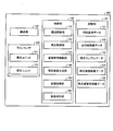
次に、本実施例に係る紙幣の真偽判別を行う紙幣真偽判別装置100の内部構成を説明する。図3は、紙幣真偽判別装置100の内部構成を示すブロック図である。
Next, the internal configuration of the bill authenticity discriminating apparatus 100 that performs true / false discrimination of bills according to the present embodiment will be described. FIG. 3 is a block diagram showing the internal configuration of the bill authenticity determination device 100.
図3に示すように、紙幣真偽判別装置100は、紙幣を1枚ずつ搬送する搬送部110と、搬送部110に取り付けられていて、搬送部110の搬送してきた紙幣の画像情報を取得するラインセンサ120と記憶部130と制御部140とを有する。
As illustrated in FIG. 3, the bill authenticity determination device 100 acquires the image information of the banknotes that are attached to the transport unit 110 that transports banknotes one by one and the transport unit 110 and that has been transported by the transport unit 110. A line sensor 120, a storage unit 130, and a control unit 140 are included.
記憶部130は、不揮発性メモリ等からなる記憶デバイスである。記憶部130は、判別基準データ131、点灯時画像データ132、残光サンプルデータ133、残光強度画像データ134及び残光減衰率画像データ135を有する。
The storage unit 130 is a storage device composed of a nonvolatile memory or the like. The storage unit 130 includes discrimination reference data 131, lighting image data 132, afterglow sample data 133, afterglow intensity image data 134, and afterglow attenuation rate image data 135.
判別基準データ131は、紙幣の真偽判別処理に先立って予め記憶されるデータであって、紙幣真偽判別装置100に搬送された紙幣の真偽を判別する際に使用する基準の画像データと、当該基準データを用いて算出される評価値の紙幣の真偽判別に係る閾値とを有している。
The discrimination reference data 131 is data that is stored in advance prior to the bill authenticity discrimination processing, and is reference image data that is used when discriminating the authenticity of a bill conveyed to the bill authenticity discrimination device 100. , And a threshold value for determining the authenticity of the bill of the evaluation value calculated using the reference data.
点灯時画像データ132は、発光ユニット121の点灯中に受光ユニット123で受光した紙幣の透過光の強度を、図1で示した単位検出領域ごとに記憶したデータである。
The lighting-time image data 132 is data in which the transmitted light intensity of the banknote received by the light receiving unit 123 while the light emitting unit 121 is turned on is stored for each unit detection area shown in FIG.
残光サンプルデータ133は、発光ユニット121の点灯停止後に受光ユニット123で受光した紙幣の残光の強度を、図1で示した単位検出領域ごとに記憶したデータである。残光サンプルデータ133は、例えば、発光ユニット121の点灯停止後に、点灯停止後t3時経過時点、t4時経過時点、t5時経過時点、t6時経過時点(t3<t4<t5<t6とする)の4つのタイミングで取得した残光強度の4サンプル値を取得する。取得する残光のサンプル数について4サンプルに限定されるものではなく、2サンプルでも5サンプル以上であってもよい。即ち、残光サンプルデータ133は、発光ユニット121の点灯停止後の所定時間経過後に間隔を隔てて2回以上のサンプルを行うことによって得られる。
The afterglow sample data 133 is data in which the intensity of the afterglow of the banknote received by the light receiving unit 123 after the light emitting unit 121 is turned off is stored for each unit detection area shown in FIG. The afterglow sample data 133 is, for example, after the light emitting unit 121 is turned off, at a time t3 elapsed, a time t4 elapsed, a time t5 elapsed, a time t6 elapsed (t3 <t4 <t5 <t6). 4 sample values of afterglow intensity acquired at the four timings are acquired. The number of afterglow samples to be acquired is not limited to 4 samples, and may be 2 samples or 5 samples or more. That is, the afterglow sample data 133 is obtained by performing the sample two or more times at intervals after a predetermined time has elapsed after the lighting unit 121 has stopped lighting.
残光強度画像データ134は、例えば、残光サンプルデータ133から生成されたデータであって、それぞれの画素値を、残光サンプルデータ133に含まれる4つのタイミングで取得した4つのサンプル値の合計値とする画像である。本実施例ではこのように残光強度画像データ134の画素値を残光サンプルデータ133に含まれる4つのタイミングで取得した4つサンプル値の合計値としたが、本発明はこれに限定されるものではない。他の例として、残光強度画像データ134の画素値を残光サンプルデータ133に含まれる4つのタイミングで取得した4つのサンプル値の平均値としてもよい。また、例えば、残光強度画像データ134の画素値を残光サンプルデータ133に含まれる4つのタイミングで取得したいずれか1つのサンプル値としてもよい。
The afterglow intensity image data 134 is, for example, data generated from the afterglow sample data 133, and each pixel value is a sum of four sample values acquired at four timings included in the afterglow sample data 133. It is an image as a value. In this embodiment, the pixel value of the afterglow intensity image data 134 is set to the total value of the four sample values acquired at the four timings included in the afterglow sample data 133 as described above, but the present invention is limited to this. It is not a thing. As another example, the pixel value of the afterglow intensity image data 134 may be an average value of four sample values acquired at four timings included in the afterglow sample data 133. Further, for example, the pixel value of the afterglow intensity image data 134 may be any one sample value acquired at four timings included in the afterglow sample data 133.
残光減衰率画像データ135は、残光サンプルデータ133から生成されたデータであって、それぞれの画素値を、残光サンプルデータ133の発光ユニット121の点灯停止後の所定時間経過時であるt3時点のサンプル値から発光ユニット121の点灯停止後t6時点のサンプル値を減算して得られた値を、(t6-t3)で除算することによって算出される値とする画像である。本実施例は、このように残光減衰率画像データ135の画素値は、発光ユニット121の点灯停止後t3時からt6時までの間に残光強度の時間当たりの減少量としたが、本発明はこれに限定されるものではない。例えば、残光サンプルデータ133としてサンプル取得したいずれの2つの時点の情報に基づいてその2つの時点間における残光強度の時間当たりの減少量としてもよい。また、例えば、発光ユニット121の点灯停止後所定時間経過時点であるt3時の残光強度に対する、発光ユニット121の点灯停止後のt6時点の残光強度の割合としてもよい。
The afterglow decay rate image data 135 is data generated from the afterglow sample data 133, and each pixel value is set to t3 when a predetermined time elapses after the light emitting unit 121 of the afterglow sample data 133 is turned off. This is an image obtained by dividing a value obtained by subtracting the sample value at time t6 after the lighting unit 121 is turned off from the sample value at time, by dividing by (t6−t3). In the present embodiment, the pixel value of the afterglow attenuation rate image data 135 is set as the amount of decrease in the afterglow intensity per time between t3 and t6 after the lighting unit 121 stops lighting. The invention is not limited to this. For example, the afterglow intensity may be reduced per hour based on information on any two time points acquired as the afterglow sample data 133. Further, for example, the ratio of the afterglow intensity at the time t6 after the light emitting unit 121 stops lighting may be the ratio of the afterglow intensity at the time t3 when the predetermined time has elapsed after the light emitting unit 121 stops lighting.
制御部140は、紙幣真偽判別装置100の全体を制御する制御部であり、搬送制御部141、発光制御部142、画像取得制御部143、残光画像生成部144、金種取得部145及び真偽判別部146を有する。実際には、この機能部に対応するプログラムを図示しないROMや不揮発性メモリに記憶しておき、このプログラムをCPU(Central Processing Unit)にロードして実行することにより、対応するプロセスを実行させることになる。
The control unit 140 is a control unit that controls the entire bill authenticity determination device 100, and includes a conveyance control unit 141, a light emission control unit 142, an image acquisition control unit 143, an afterglow image generation unit 144, a denomination acquisition unit 145, and A true / false determination unit 146 is included. Actually, a program corresponding to this functional unit is stored in a ROM or non-volatile memory (not shown), and this program is loaded into a CPU (Central Processing Unit) and executed to execute the corresponding process. become.
搬送制御部141は、送られてきた紙幣を搬送して所定の搬送速度でラインセンサ120を通過させるように制御する。また、ラインセンサ120を通過させることによってラインセンサ120で取得した情報に基づいて真偽判別が行われて、その判別結果を上位制御部に送る。
The conveyance control unit 141 controls the conveyed banknotes to pass through the line sensor 120 at a predetermined conveyance speed. Moreover, authenticity determination is performed based on the information acquired by the line sensor 120 by passing the line sensor 120, and the determination result is sent to the host controller.
発光制御部142は、ラインセンサ120の発光ユニット121に指示することによって所定のサイクルで点灯と消灯を繰り返す。また、発光制御部142は、発光ユニット121への点灯の指示に併せて受光ユニット123へ点灯時用に回路のゲインを下げるように指示を行う。また、発光制御部142は、発光ユニット121への消灯の指示に併せて受光ユニット123への残光検知用に回路ゲインを上げるように指示を行う。
The light emission control unit 142 repeats lighting and extinguishing in a predetermined cycle by instructing the light emitting unit 121 of the line sensor 120. In addition, the light emission control unit 142 instructs the light receiving unit 123 to reduce the gain of the circuit for lighting together with the lighting instruction to the light emitting unit 121. In addition, the light emission control unit 142 instructs the light emitting unit 121 to increase the circuit gain for detecting the afterglow to the light receiving unit 123 along with the instruction to turn off the light emitting unit 121.
画像取得制御部143は、紙幣がラインセンサ120を通過する際に、発光ユニット121の点灯開始から所定時間経過したタイミングで受光ユニット123が取得した情報を点灯時画像データ132に書き込む。また、画像取得制御部143は、発光ユニット121の消灯から所定時間経過の4つのタイミングで受光ユニット123が取得したサンプル値を残光サンプルデータ133に書き込む。点灯時画像データ132の1画像及び残光サンプルデータ133の4サンプル値はそれぞれ、発光ユニット121の点灯サイクルと、搬送部110の搬送速度と、紙幣の搬送方向に対する長さとによって決定される走査線数と、受光ユニット123が有する受光部124の個数を乗算して得られた数分の画素を有する画像である。
The image acquisition control unit 143 writes the information acquired by the light receiving unit 123 to the lighting-time image data 132 when a predetermined time has elapsed from the start of lighting of the light-emitting unit 121 when the bill passes the line sensor 120. In addition, the image acquisition control unit 143 writes the sample values acquired by the light receiving unit 123 at four timings after the elapse of a predetermined time from the extinction of the light emitting unit 121 to the afterglow sample data 133. One image of the lighting-time image data 132 and four sample values of the afterglow sample data 133 are scanning lines determined by the lighting cycle of the light emitting unit 121, the conveyance speed of the conveyance unit 110, and the length of the banknote in the conveyance direction, respectively. It is an image having as many pixels as the number obtained by multiplying the number by the number of light receiving units 124 included in the light receiving unit 123.
残光画像生成部144は、残光サンプルデータ133に含まれる、励起光照射停止からの経過時間が異なる4枚の残光画像に基づいて、残光強度画像データ134及び残光減衰率画像データ135を生成する。残光強度画像データ134のそれぞれの画素値は、残光サンプルデータ133に含まれる、励起光照射停止からの経過時間が異なる4枚の残光画像の同じ位置の画素の画素値の合計値である。また、残光減衰率画像データ135のそれぞれの画素値は、残光サンプルデータ133に含まれる、励起光照射停止からの経過時間が一番短い残光画像の同じ位置の画素の画素値と、励起光照射停止からの経過時間が一番長い残光画像の同じ位置のサンプル値の差分を、経過時間の差分で除算して得られた値である。
The afterglow image generation unit 144 uses the afterglow image data 134 and the afterglow attenuation rate image data based on the four afterglow images included in the afterglow sample data 133 and having different elapsed times from the stop of excitation light irradiation. 135 is generated. Each pixel value of the afterglow intensity image data 134 is a total value of the pixel values of the pixels at the same position in the four afterglow images included in the afterglow sample data 133 and having different elapsed times from the excitation light irradiation stop. is there. In addition, each pixel value of the afterglow attenuation rate image data 135 includes the pixel value of the pixel at the same position in the afterglow image that is included in the afterglow sample data 133 and has the shortest elapsed time from the excitation light irradiation stop, This is a value obtained by dividing the difference between the sample values at the same position in the afterglow image with the longest elapsed time from the stop of excitation light irradiation by the difference in elapsed time.
金種取得部145は、図示しない搬送路上流に設けられた金種識別部が判別した紙幣の金種及び紙幣の方向を取得する処理部である。
The denomination acquiring unit 145 is a processing unit that acquires the denomination of the banknote and the direction of the banknote determined by the denomination identifying unit provided upstream of the conveyance path (not shown).
真偽判別部146は、残光強度画像データ134と残光減衰率画像データ135と、金種取得部145によって取得した判別対象の紙幣の金種及び紙幣の方向の情報を基に判別基準データ131に含まれる金種・方向別の基準画像データを選択し、ラインセンサ120で取得した画像データに対応する紙幣が、金種取得部145によって取得した金種・方向の真券であるか否かの判別を行う。
The authenticity determination unit 146 determines the reference standard data based on the afterglow intensity image data 134, the afterglow attenuation rate image data 135, and the information on the denomination of the banknote to be determined and the direction of the banknote acquired by the denomination acquisition unit 145. Whether or not the banknote corresponding to the image data acquired by the line sensor 120 by selecting the reference image data for each denomination / direction included in 131 is a genuine note of the denomination / direction acquired by the denomination acquiring unit 145. Is determined.
次に、図1に示した発光部122、受光部124を含むラインセンサ120の構成を、図4を用いて説明する。図4は、紙幣の搬送方向に対して垂直な面によるラインセンサ120の断面図である。
Next, the configuration of the line sensor 120 including the light emitting unit 122 and the light receiving unit 124 illustrated in FIG. 1 will be described with reference to FIG. FIG. 4 is a cross-sectional view of the line sensor 120 taken along a plane perpendicular to the bill conveyance direction.
ラインセンサ120は、紙幣搬送路を挟んで上側に発光ユニット121、下側に受光ユニット123を有している。発光ユニット121は、等間隔で配置された発光部122を複数備えている。また、受光ユニット123は、発光ユニット121のそれぞれの発光部122に対応する位置に受光部124を有する。それぞれの発光部122は、搬送路を通る紙幣に励起光を照射し、それぞれの発光部122に対応する位置に配置されている受光部124は、励起光の照射にともなう透過光や照射停止後の残光を検知する。
The line sensor 120 has a light emitting unit 121 on the upper side and a light receiving unit 123 on the lower side across the banknote conveyance path. The light emitting unit 121 includes a plurality of light emitting units 122 arranged at equal intervals. In addition, the light receiving unit 123 includes a light receiving unit 124 at a position corresponding to each light emitting unit 122 of the light emitting unit 121. Each light emitting unit 122 irradiates the bills passing through the conveyance path with excitation light, and the light receiving unit 124 arranged at a position corresponding to each light emitting unit 122 transmits transmitted light accompanying irradiation of excitation light or after irradiation is stopped. Detects afterglow.
発光部122は、光源122bの点灯/消灯を制御したり発光強度の調整を行う発光部基板122aと、赤外光を発光するLEDなどの光源122bと、透明なガラス又は樹脂からなる透明部材122dとを含んでいる。受光部124は、透明なガラス又は樹脂からなる透明部材124aと透明部材124aを通った光を検知する受光センサ124dと、受光センサ124dが検知した情報を増幅したりデジタル変換する受光部基板124eを含んでいる。また、受光部基板124eは、光源122bを点灯中の透過光と、光源122bを消灯中の残光では光の強度の差が大きすぎるため、受光センサ124dの増幅アンプ回路のゲイン(受光感度)の調整をする機能を有しており、制御部140からの指示に基づいて増幅アンプ回路のゲインを変更することができる。
The light emitting unit 122 includes a light emitting unit substrate 122a that controls turning on / off of the light source 122b and adjustment of light emission intensity, a light source 122b such as an LED that emits infrared light, and a transparent member 122d made of transparent glass or resin. Including. The light receiving unit 124 includes a transparent member 124a made of transparent glass or resin, a light receiving sensor 124d that detects light passing through the transparent member 124a, and a light receiving unit substrate 124e that amplifies or digitally converts information detected by the light receiving sensor 124d. Contains. Further, since the difference in light intensity between the transmitted light when the light source 122b is turned on and the afterglow when the light source 122b is turned off is too large, the light receiving unit substrate 124e has a gain (light receiving sensitivity) of the amplification amplifier circuit of the light receiving sensor 124d. The gain of the amplification amplifier circuit can be changed based on an instruction from the control unit 140.
発光部122の光源122bが発光した赤外光が搬送路を通過中の紙幣に照射されると、紙幣を透過した光は受光センサ124dへ入射し、受光センサ124dが透過光を検知する。また、光源122bの消灯後には、紙幣の残光が受光センサ124dへ入射し、受光センサ124dが残光を検知する。このようにして、紙幣に励起光を照射した時の点灯時の情報と、励起光の照射停止後の残光の強度の情報とを取得することができる。
When the infrared light emitted from the light source 122b of the light emitting unit 122 is applied to the banknote passing through the transport path, the light transmitted through the banknote enters the light receiving sensor 124d, and the light receiving sensor 124d detects the transmitted light. Further, after the light source 122b is turned off, the afterglow of the bill enters the light receiving sensor 124d, and the light receiving sensor 124d detects the afterglow. In this way, it is possible to acquire information at the time of lighting when the banknote is irradiated with excitation light and information on the intensity of afterglow after the excitation light irradiation is stopped.
ここで、上述の説明には受光部フィルタ124bと集光レンズ124cの説明はなかったが、ある条件下では受光部124に受光部フィルタ124bと集光レンズ124cを設けることができる。燐光を測定する時には光源122bは消灯しており、発光側のフィルタは不要である。集光レンズ124cは励起される燐光が弱ければ集光するために設けることができる。また、励起された燐光が可視光成分と赤外光成分の両方を有しており、いずれか1方の光成分を評価したいときには受光部フィルタ124bを設けてもよい。
Here, the light-receiving unit filter 124b and the condensing lens 124c are not described in the above description, but the light-receiving unit filter 124b and the condensing lens 124c can be provided in the light-receiving unit 124 under certain conditions. When measuring phosphorescence, the light source 122b is extinguished, and a filter on the light emission side is unnecessary. The condensing lens 124c can be provided to condense if the excited phosphorescence is weak. Further, when the excited phosphorescence has both a visible light component and an infrared light component, and it is desired to evaluate either one of the light components, a light receiving section filter 124b may be provided.
次に、図3に示した紙幣真偽判別装置100のデータ構成を、図5を用いて説明する。
Next, the data configuration of the bill authenticity discriminating apparatus 100 shown in FIG. 3 will be described with reference to FIG.
判別基準データ131は、搬送された紙幣の真偽の判別処理で使用する真偽判別基準情報を含む。また、真偽判別基準情報は、残光強度画像基準情報と残光減衰率画像基準情報とを含む。残光強度画像基準情報は、金種・方向ごとに判別閾値と基準画像データとを有する。基準画像データは、真券を使って取得した残光強度画像データ134である。また、判別閾値は、搬送された紙幣の残光強度画像データ134と基準画像データから算出した2つの画像の類似度を示す評価値の、搬送された紙幣が当該金種の真券と判別する下限値を示す。
The discrimination reference data 131 includes authenticity discrimination reference information used in the authenticity discrimination processing of the conveyed banknote. The authenticity discrimination reference information includes afterglow intensity image reference information and afterglow attenuation rate image reference information. The afterglow intensity image reference information includes a discrimination threshold value and reference image data for each denomination and direction. The reference image data is afterglow intensity image data 134 acquired using a genuine note. Further, the determination threshold value is an evaluation value indicating the similarity between two images calculated from the afterglow intensity image data 134 of the conveyed banknote and the reference image data, and the conveyed banknote is determined to be a genuine note of the denomination. Indicates the lower limit.
また、残光減衰率画像基準情報は、金種・方向ごとに判別閾値と基準画像データとを有する。基準画像データは、真券を使って取得した残光減衰率画像データ135である。また、判別閾値は、搬送された紙幣の残光減衰率画像データ135と基準画像データから算出した2つの画像の類似度を示す評価値の、搬送された紙幣が当該金種の真券と判別する下限値を示す。
Further, the afterglow attenuation rate image reference information has a discrimination threshold value and reference image data for each denomination and direction. The reference image data is afterglow attenuation rate image data 135 acquired using a genuine note. The discrimination threshold is an evaluation value indicating the similarity between two images calculated from the afterglow decay rate image data 135 and the reference image data of the conveyed banknote, and the conveyed banknote is determined to be a genuine note of the denomination. Indicates the lower limit value.
図5の判別基準データ131の例を示す。残光強度画像基準情報の金種1のA方向に対する真偽の判別閾値が「v11A」で基準画像データとして真券の金種1のA方向の基準となる残光強度画像データ134を有し、金種1のB方向に対する真偽の判別閾値が「v11B」で基準画像データとして真券の金種1のB方向の基準となる残光強度画像データ134を有し、金種2のA方向に対する真偽の判別閾値が「v12A」で基準画像データとして真券の金種2のA方向の基準となる残光強度画像データ134を有し、金種3のA方向に対する真偽の判別閾値が「v13A」で基準画像データとして真券の金種3のA方向の基準となる残光強度画像データ134を有していることを示している。また、残光減衰率画像基準情報の金種1のA方向に対する真偽の判別閾値が「v21A」で基準画像データとして真券の金種1のA方向の基準となる残光減衰率画像データ135を有し、残光減衰率画像基準情報の金種1のB方向に対する真偽の判別閾値が「v21B」で基準画像データとして真券の金種1のB方向の基準となる残光減衰率画像データ135を有し、金種2のA方向に対する真偽の判別閾値が「v22A」で基準画像データとして真券の金種2のA方向の基準となる残光減衰率画像データ135を有し、金種3のA方向に対する真偽の判別閾値が「v23A」で基準画像データとして真券の金種3のA方向の基準となる残光減衰率画像データ135を有していることを示している。ここで、搬送方向の4方向をA方向、B方向、C方向、D方向として表す。
An example of the discrimination reference data 131 in FIG. 5 is shown. The afterglow intensity image reference information of the afterglow intensity image reference information with respect to the A direction of the denomination 1 is “v11A” and the afterglow intensity image data 134 serving as a reference for the A direction of the denomination 1 of the genuine note is provided as reference image data. , The true / false discrimination threshold for the B direction of the denomination 1 is “v11B”, and the afterglow intensity image data 134 serving as the reference for the B direction of the genuine denomination 1 is included as the reference image data. The true / false discrimination threshold for the direction is “v12A”, and the afterglow intensity image data 134 is used as the reference for the A direction of the genuine note denomination 2 as the reference image data. It shows that the threshold value is “v13A” and the afterglow intensity image data 134 that is the reference in the A direction of the genuine denomination 3 is used as the reference image data. In addition, the afterglow attenuation rate image data used as the reference in the A direction of the genuine money type 1 as the reference image data when the true / false discrimination threshold for the A direction of the denomination 1 of the afterglow rate image reference information is “v21A” 135, and the afterglow attenuation which becomes the reference in the B direction of the genuine money type 1 as the reference image data when the true / false discrimination threshold for the B direction of the money type 1 of the afterglow attenuation rate image reference information is “v21B”. The afterglow attenuation rate image data 135 serving as the reference in the A direction of the genuine money type 2 is used as the reference image data with the authenticity determination threshold value “v22A” for the A direction of the money type 2. And the afterglow attenuation rate image data 135 which is the reference in the A direction of the genuine note denomination 3 is used as the reference image data with the true / false discrimination threshold for the A direction of the denomination 3 being “v23A”. Is shown. Here, four directions in the transport direction are expressed as an A direction, a B direction, a C direction, and a D direction.
残光サンプルデータ133は、励起光照射停止からの経過時間が異なる4つのタイミングで取得した4つのサンプルデータである。励起光照射停止からの経過時間の小さな順に残光サンプル値1、残光サンプル値2、残光サンプル値3及び残光サンプル値4のデータを有する。
The afterglow sample data 133 is four sample data acquired at four timings with different elapsed times from the excitation light irradiation stop. Data of afterglow sample value 1, afterglow sample value 2, afterglow sample value 3, and afterglow sample value 4 are included in ascending order of elapsed time from the stop of excitation light irradiation.
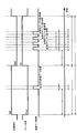
次に、図3に示した紙幣真偽判別装置100における本実施例の紙幣の画像取得に係る処理タイミングを、図6を用いて説明する。図6は、ラインセンサ120の発光ユニット121の点灯及び消灯の1サイクルにおける受光ユニット123の増幅回路のゲインの切替と受光ユニット123による画像データ取得タイミングを示す図である。
Next, the processing timing related to the image acquisition of the banknote of the present embodiment in the banknote authenticity discriminating apparatus 100 shown in FIG. 3 will be described with reference to FIG. FIG. 6 is a diagram illustrating the gain switching of the amplification circuit of the light receiving unit 123 and the image data acquisition timing by the light receiving unit 123 in one cycle of turning on and off the light emitting unit 121 of the line sensor 120.
図6に示すように、発光ユニット121は、t1時で点灯してから、t4時で消灯し、再びt13時で点灯するまでを1サイクルとして動作する。また当該1サイクルの時間の長さはL1で固定であり、点灯を開始してから消灯するまでの点灯中時間の長さがL2で、消灯してから点灯するまでの消灯中時間の長さがL3である。時間L2とL3は同じ長さであってもよい。また、受光ユニット123の増幅回路のゲインの切替は発光ユニット121の点灯及び消灯と同期して、t1時及びt13時の発光ユニット121の点灯と同期して、受光ユニット123の増幅回路のゲインを下げる。また、t4時の発光ユニット121の消灯と同期して、受光ユニット123の増幅回路のゲインを上げる。
As shown in FIG. 6, the light emitting unit 121 operates as one cycle from turning on at t1, turning off at t4, and turning on again at t13. The length of one cycle is fixed at L1, and the length of the lighting time from the start of lighting until turning it off is L2, and the length of the turning-off time from turning off the light to turning on Is L3. Times L2 and L3 may be the same length. The gain of the amplifier circuit of the light receiving unit 123 is switched in synchronization with the lighting and extinguishing of the light emitting unit 121, and the gain of the amplifier circuit of the light receiving unit 123 is synchronized with the lighting of the light emitting unit 121 at t1 and t13. Lower. Further, the gain of the amplifier circuit of the light receiving unit 123 is increased in synchronization with the light emitting unit 121 being turned off at t4.
また、点灯のタイミング(t1)から所定時間(L4)を経過したt2時から所定時間内(L6)のt3時までの間に、受光ユニット123で検知した情報を点灯時画像データ132の一部の内容として取り込む。1回の情報の取り込みによって紙幣の搬送方向に垂直な1つの走査線上の領域の点灯時画像に対応するデータを取得することとなる。
Further, information detected by the light receiving unit 123 is part of the lighting-time image data 132 from t2 when the predetermined time (L4) has elapsed from the lighting timing (t1) to t3 within the predetermined time (L6). Import as content. Data corresponding to a lighting image of an area on one scanning line perpendicular to the banknote transport direction is acquired by capturing information once.
また、消灯のタイミング(t4)から所定時間(L5)を経過したt5時から所定時間内(L6)のt6時までの間に、受光ユニット123で検知した情報を残光サンプルデータ133の残光サンプル値1の一部の内容として取り込む。また、t6時から所定時間(L7)経過したt7時から所定時間内(L6)のt8時までの間に、受光ユニット123で検知した情報を残光サンプルデータ133の残光サンプル値2の一部の内容として取り込む。また、t8時から所定時間(L7)経過したt9時から所定時間内(L6)のt10時までの間に、受光ユニット123で検知した情報を残光サンプルデータ133の残光サンプル値3の一部の内容として取り込む。また、t10時から所定時間(L7)経過したt11時から所定時間内(L6)の時間t12までの間に、受光ユニット123で検知した情報を残光サンプルデータ133の残光サンプル値4の一部の内容として取り込む。
Further, the information detected by the light receiving unit 123 from the time t5 when the predetermined time (L5) has elapsed from the timing of turning off (t4) to the time t6 within the predetermined time (L6) is the afterglow of the afterglow sample data 133. Capture as part of sample value 1. In addition, the information detected by the light receiving unit 123 between the time t7 when the predetermined time (L7) has elapsed from the time t6 and the time t8 within the predetermined time (L6) is one of the afterglow sample values 2 of the afterglow sample data 133. Import as part contents. Further, the information detected by the light receiving unit 123 is stored in the afterglow sample value 133 of the afterglow sample data 133 from t9 when the predetermined time (L7) has elapsed from t8 to t10 within the predetermined time (L6). Import as part contents. Further, the information detected by the light receiving unit 123 is stored in the afterglow sample value 4 of the afterglow sample data 133 from t11 when the predetermined time (L7) has elapsed from t10 to t12 within the predetermined time (L6). Import as part contents.
次に、図3に示した紙幣真偽判別装置100における、画像データ取得処理の処理手順を説明する。図7は、紙幣真偽判別装置100における、画像データ取得処理の処理手順を示すフローチャートである。
Next, a processing procedure of image data acquisition processing in the bill authenticity discrimination device 100 shown in FIG. 3 will be described. FIG. 7 is a flowchart showing a processing procedure of image data acquisition processing in the bill authenticity determination device 100.
搬送部110によって搬送されてきた紙幣が、紙幣画像の読取の開始位置に来たか否かを検知する(ステップS101)。紙幣が紙幣画像の読取の開始位置に来たことを検知していない場合(ステップS101;No)には、到来を検知するまで待ちを続ける。そして、紙幣の到来を検知したならば(ステップS101;Yes)、画像取得制御部143は、点灯時画像データ132、残光サンプルデータ133、残光強度画像データ134及び残光減衰率画像データ135を初期化するなどの搬送されてきた紙幣の画像取得のための準備処理を行う(ステップS102)。
It is detected whether the banknote conveyed by the conveyance part 110 has come to the reading start position of a banknote image (step S101). When it is not detected that the banknote has arrived at the reading start position of the banknote image (step S101; No), the process continues to wait until the arrival is detected. If the arrival of the banknote is detected (step S101; Yes), the image acquisition control unit 143 turns on the image data 132 at the time of lighting, the afterglow sample data 133, the afterglow intensity image data 134, and the afterglow attenuation rate image data 135. A preparation process for obtaining an image of the conveyed banknote is performed (step S102).
また、発光制御部142は、ラインセンサ120の受光ユニット123の増幅回路のゲインを下げる指示を行う(ステップS103)とともに、ラインセンサ120の発光ユニット121に点灯の指示を行う(ステップS104)。次に、画像取得制御部143は、点灯時画像データ132の取得タイミングであるか否かの判定を行い(ステップS105)、点灯時画像データ132の取得タイミングとなった場合(ステップS105:Yes)には、受光ユニット123で検知した情報を点灯時画像データ132の一部の内容として取り込む(ステップS106)。また、点灯時画像データ132の取得タイミングになっていない場合(ステップS105:No)には、ステップS105に戻ることによって点灯時画像データ132の取得タイミングの待ち合わせを行う。
Further, the light emission control unit 142 gives an instruction to lower the gain of the amplification circuit of the light receiving unit 123 of the line sensor 120 (Step S103) and instructs the light emitting unit 121 of the line sensor 120 to turn on (Step S104). Next, the image acquisition control unit 143 determines whether or not it is the acquisition timing of the lighting-time image data 132 (step S105), and when it is the acquisition timing of the lighting-time image data 132 (step S105: Yes). The information detected by the light receiving unit 123 is taken in as part of the contents of the lighting-time image data 132 (step S106). If it is not the timing for obtaining the lighting-time image data 132 (step S105: No), the process returns to step S105 to wait for the timing for obtaining the lighting-time image data 132.
次に、発光制御部142は、発光ユニット121の消灯のタイミングであるか否かの判定を行い(ステップS107)、発光ユニット121の消灯のタイミングとなった場合(ステップS107;Yes)には、ラインセンサ120の発光ユニット121に消灯の指示を行う(ステップS108)とともに、ラインセンサ120の受光ユニット123の増幅回路のゲインを上げる指示を行う(ステップS109)。発光ユニット121の消灯のタイミングとなっていない場合(ステップS107;No)には、ステップS107に戻ることによって発光ユニット121の消灯のタイミングの待ち合わせを行う。
Next, the light emission control unit 142 determines whether or not it is the timing for turning off the light emitting unit 121 (step S107). When the timing for turning off the light emitting unit 121 is reached (step S107; Yes), The light emitting unit 121 of the line sensor 120 is instructed to turn off (step S108), and the instruction to increase the gain of the amplifier circuit of the light receiving unit 123 of the line sensor 120 is issued (step S109). When it is not the timing for turning off the light emitting unit 121 (step S107; No), the process returns to step S107 to wait for the timing for turning off the light emitting unit 121.
次に、画像取得制御部143は、残光サンプルデータ133の取得タイミングであるか否かの判定を行い(ステップS110)、まだ残光サンプルデータ133の取得タイミングではない場合(ステップS110;No)には、ステップS110に戻ることによって残光サンプルデータ133の取得タイミングの待ち合わせを行う。また、残光サンプルデータ133の取得タイミングとなった場合(ステップS110;Yes)には、受光ユニット123で検知した情報を残光サンプルデータ133の一部の内容として取り込む(ステップS111)。残光画像の取得タイミングは図6に示したように、発光ユニット121の点灯、消灯の1サイクル内で消灯中に4回あり、取得するタイミングによって残光サンプルデータ133の残光サンプル値1~4のいずれのデータとして取り込むのかが決まる。
Next, the image acquisition control unit 143 determines whether it is the acquisition timing of the afterglow sample data 133 (step S110), and when it is not yet the acquisition timing of the afterglow sample data 133 (step S110; No). In step S110, the process waits for the afterglow sample data 133 acquisition timing. If it is time to acquire the afterglow sample data 133 (step S110; Yes), the information detected by the light receiving unit 123 is captured as a part of the afterglow sample data 133 (step S111). As shown in FIG. 6, the afterglow image acquisition timing is four times during the turn-off and turn-off of the light emitting unit 121, and the afterglow sample value 1 to 1 of the afterglow sample data 133 depends on the acquisition timing. 4 is determined as the data to be captured.
次に、発光ユニット121の点灯、消灯の1サイクル内にある4回の残光サンプル値の取得タイミングにおける4個のサンプル値を取得済みか否かの判定を行って(ステップS112)、まだ取得済みとなっていない残光画像がある場合(ステップS112;No)には、ステップS110に戻ることによって、未取得の残光サンプル値の取得タイミングの待ち合わせを行う。また、既に4回の残光サンプル値の取得タイミングにおける4サンプル値に対する情報を取得済みである場合(ステップS112;Yes)には、残光画像生成部144は、直前のステップS110からステップ112で取得した残光サンプルデータ133に基づいて、残光強度画像データ134の対応する画素値を算出して、算出した内容で残光強度画像データ134を更新する(ステップS113)。また、残光画像生成部144は、直前のステップS110からステップ112で取得した残光サンプルデータ133に基づいて、残光減衰率画像データ135の対応する画素値を算出して、算出した内容で残光減衰率画像データ135を更新する(ステップS114)。
Next, it is determined whether or not four sample values have been acquired at the acquisition timing of four afterglow sample values within one cycle of turning on / off the light emitting unit 121 (step S112), and still acquired. If there is an afterglow image that has not been completed (step S112; No), the process returns to step S110 to wait for acquisition timing of an unacquired afterglow sample value. In addition, when the information for the four sample values at the acquisition timing of the four afterglow sample values has already been acquired (step S112; Yes), the afterglow image generation unit 144 performs the process from step S110 to step 112 immediately before. Based on the acquired afterglow sample data 133, the corresponding pixel value of the afterglow intensity image data 134 is calculated, and the afterglow intensity image data 134 is updated with the calculated content (step S113). Further, the afterglow image generation unit 144 calculates the corresponding pixel value of the afterglow attenuation rate image data 135 based on the afterglow sample data 133 acquired in the immediately preceding step S110 to step 112, and the calculated content. Afterglow decay rate image data 135 is updated (step S114).
次に、画像取得制御部143は、紙幣がラインセンサ120を通過済みか否かの判定を行って(ステップS115)、まだ紙幣がラインセンサ120を通過していない場合(ステップS115;No)には、ステップS103に戻る。また、既に紙幣がラインセンサ120を通過の場合(ステップS115;Yes)には、処理を終了する。
Next, the image acquisition control unit 143 determines whether or not the banknote has passed the line sensor 120 (step S115), and when the banknote has not yet passed the line sensor 120 (step S115; No). Returns to step S103. Moreover, a process is complete | finished when a banknote has already passed the line sensor 120 (step S115; Yes).
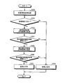
次に、図3に示した紙幣真偽判別装置100における、紙幣の真偽判別処理の処理手順を説明する。図8は、紙幣真偽判別装置100における、紙幣の真偽判別処理の処理手順を示すフローチャートである。
Next, a processing procedure of bill authenticity discrimination processing in the bill authenticity discriminating apparatus 100 shown in FIG. 3 will be described. FIG. 8 is a flowchart showing a processing procedure of bill authenticity determination processing in the bill authenticity determination device 100.
図8に示す紙幣の真偽判別処理は、図7に示した紙幣の画像データ取得処理に引き続いて動作する。金種取得部145は、搬送路上流部に設けた金種識別部で判別した紙幣の金種及び紙幣の方向の情報を取得する(ステップS201)。
The bill authenticity determination processing shown in FIG. 8 operates following the bill image data acquisition processing shown in FIG. The denomination acquiring unit 145 acquires information on the denomination of the banknote and the direction of the banknote determined by the denomination identifying unit provided in the upstream portion of the conveyance path (step S201).
ステップS201で金種・方向の情報が取得できた場合(ステップS202;Yes)には、真偽判別部146は、残光強度画像データ134と判別基準データ131の残光強度画像基準情報のステップS201で取得された金種・方向に対応する基準画像データとから、当該2つの画像の類似度を示す評価値を算出する(ステップS203)。真偽判別部146は、ステップS203で算出された評価値と、判別基準データ131の残光強度画像基準情報のステップS201で取得された金種・方向に対応する判別閾値とを比較して(ステップS204)、ステップS203で算出された評価値が当該判別閾値以上である場合(ステップS204;Yes)には、ステップ205に移行する。ここで、評価値の例として相関係数を使用することができる。
When the denomination / direction information can be acquired in step S201 (step S202; Yes), the authenticity determination unit 146 performs the afterglow intensity image reference information step of the afterglow intensity image data 134 and the determination reference data 131. An evaluation value indicating the similarity between the two images is calculated from the reference image data corresponding to the denomination and direction acquired in S201 (step S203). The authenticity determination unit 146 compares the evaluation value calculated in step S203 with the determination threshold corresponding to the denomination / direction acquired in step S201 of the afterglow intensity image reference information of the determination reference data 131 ( If the evaluation value calculated in step S204 is equal to or greater than the determination threshold (step S204; Yes), the process proceeds to step 205. Here, a correlation coefficient can be used as an example of the evaluation value.
真偽判別部146は、残光減衰率画像データ135と判別基準データ131の残光減衰率画像基準情報のステップS201で取得された金種・方向に対応する基準画像データとから、当該2つの画像の類似度を示す評価値を算出する(ステップS205)。真偽判別部146は、ステップS205で算出された評価値と、判別基準データ131の残光減衰率画像基準情報のステップS201で取得された金種・方向に対応する判別閾値とを比較して(ステップS206)、ステップS205で算出された評価値が当該判別閾値以上である場合(ステップS206;Yes)には、ラインセンサ120で取得された画像に対する紙幣は真券であると判定して(ステップS207)、処理を終了する。
The authenticity determination unit 146 uses the afterglow decay rate image data 135 and the reference image data corresponding to the denomination and direction acquired in step S201 of the afterglow decay rate image reference information of the discrimination reference data 131, to determine the two An evaluation value indicating the similarity of images is calculated (step S205). The authenticity determination unit 146 compares the evaluation value calculated in step S205 with the determination threshold corresponding to the denomination / direction acquired in step S201 of the afterglow attenuation rate image reference information of the determination reference data 131. (Step S206) When the evaluation value calculated in Step S205 is equal to or greater than the determination threshold value (Step S206; Yes), it is determined that the banknote for the image acquired by the line sensor 120 is a genuine note ( Step S207) and the process is terminated.
また、ステップS205で算出された評価値がこれに対する判別閾値未満の場合(ステップS206;No)には、ラインセンサ120で取得された画像に対する紙幣は偽券と判定して(ステップS208)、処理を終了する。また、ステップ203で算出された評価値がこれに対する判別閾値未満の場合(ステップS204;No)にも、ラインセンサ120で取得された画像に対する紙幣は偽券と判定して(ステップS208)、処理を終了する。また、ステップS201で金種・方向の情報の取得ができなかった場合(ステップS202;No)にも、ラインセンサ120で取得された画像に対する紙幣は偽券と判定して(ステップS208)、処理を終了する。
If the evaluation value calculated in step S205 is less than the discrimination threshold for this (step S206; No), it is determined that the banknote for the image acquired by the line sensor 120 is a fake note (step S208), and processing is performed. Exit. Even when the evaluation value calculated in step 203 is less than the discrimination threshold for this (step S204; No), it is determined that the banknote for the image acquired by the line sensor 120 is a fake note (step S208), and processing is performed. Exit. In addition, even when the denomination / direction information cannot be acquired in step S201 (step S202; No), the banknote corresponding to the image acquired by the line sensor 120 is determined to be a fake ticket (step S208) and processed. Exit.
他の実施例としてステップS201において、点灯時画像データ132に格納された透過赤外光画像データと判別基準データ131に予め格納された金種判別基準透過赤外光データとに基づいて金種の識別を行う様にすることも可能である。
As another example, in step S201, the denomination of the denomination is determined based on the transmitted infrared light image data stored in the lighting-time image data 132 and the denomination determination reference transmission infrared light data stored in advance in the determination reference data 131. It is also possible to perform identification.
上述してきたように、本実施例では、励起光の照射によって燐光を発光する特性を有する紙幣に対して、励起光を照射して紙幣からの透過光及び紙幣の発光する燐光の残光を検知するラインセンサ120を用いて、励起光消灯後の残光強度に基づいて生成した残光強度画像データ134と、励起光消灯後の残光強度の減衰率に基づいて生成した残光減衰率画像データ135と、それぞれ事前に記憶しておいた真券に対応する残光強度基準画像と、残光減衰率基準画像との類似性を評価することによって紙幣の真偽判別を行うよう構成したので、センサ構成をシンプルにすることによってコストを抑制しつつ、厳格な紙幣の真偽判別を実現することができる。
As described above, in this embodiment, the banknotes having the characteristic of emitting phosphorescence by the excitation light irradiation are irradiated with the excitation light to detect the transmitted light from the banknote and the phosphorescence afterglow emitted from the banknote. The afterglow intensity image data 134 generated based on the afterglow intensity after the excitation light extinguishes using the line sensor 120 and the afterglow attenuation rate image generated based on the decay rate of the afterglow intensity after the excitation light extinction. Since it is configured to determine the authenticity of the banknote by evaluating the similarity between the data 135 and the afterglow intensity reference image corresponding to the genuine note stored in advance and the afterglow attenuation rate reference image, respectively. By making the sensor configuration simple, it is possible to realize strict bill authenticity discrimination while suppressing costs.
また、赤外光照射中に取得される点灯時画像データ133を取得することにより、金種識別も可能とすることができる。更に、紙幣の同一場所の透過赤外画像データ、残光強度画像と残光減衰率画像が取得できるので、紙幣上の位置を透過赤外画像データで特定し、その特定した位置に対応した残光強度画像値と残光減衰率画像値を評価できるので、真偽判別が精緻にできるとともに、燐光インク部領域を継ぎはぎするような切貼を行った偽造券に対する真偽判別能力をアップさせることができる。
Also, denomination identification can be made possible by obtaining the lighting-time image data 133 obtained during infrared light irradiation. Further, since the transmission infrared image data, the afterglow intensity image and the afterglow attenuation rate image of the same location of the banknote can be acquired, the position on the banknote is specified by the transmission infrared image data, and the residual corresponding to the specified position is determined. Since the light intensity image value and the afterglow decay rate image value can be evaluated, the authenticity determination can be made precise, and the authenticity determination capability for counterfeit tickets that have been cut and pasted so as to separate the phosphorescent ink area is increased. be able to.
なお、上述の本実施例では、赤外光で励起して赤外領域の波長で燐光発光する特徴を有する紙幣の真偽判別を行う例を説明してきたが、本発明はこれに限定されるものではない。可視光や紫外光で燐光発光するインクの存在は一般に良く知られているので、赤外光の替わりに可視光や紫外光を使うことが可能である。例えば、紫外光で励起して可視光領域の波長で燐光発光する特徴を有する紙幣を対象とした場合のラインセンサは、紫外光を照射して可視光を検知できるようなラインセンサを採用することとなる。また、紙葉類を透過しやすい赤外光と違って、紫外光は紙葉類を透過しにくいことから、紫外光を照射して可視光を検知するようなラインセンサは、紫外光を照射する面の反射光を検知するような反射型のラインセンサとなることが多い。また、本実施例では、透過型センサで説明を行ったが、反射型センサとして、発光ユニットと受光ユニットを紙幣搬送路の同一面に設置することも行える。なお、透過型センサ又は反射型センサのいずれの構造とするかは、励起光として使用する波長が赤外光、可視光又は紫外光のいずれであるかに基いて選択することが可能である。だだし、波長の長短の性質を考慮して反射型センサが優位か透過型センサが優位かは設計の現場で検討されるものである。
In addition, although the above-mentioned Example demonstrated the example which performs the authenticity discrimination | determination of the banknote which has the characteristic of exciting with infrared light and phosphorescent-emitting in the wavelength of an infrared region, this invention is limited to this. It is not a thing. The existence of ink that emits phosphorescence with visible light or ultraviolet light is generally well known, and it is possible to use visible light or ultraviolet light instead of infrared light. For example, a line sensor that can detect visible light by irradiating with ultraviolet light should be adopted as a line sensor for banknotes having a feature of being excited by ultraviolet light and emitting phosphorescence at a wavelength in the visible light region. It becomes. Also, unlike infrared light that easily passes through paper, ultraviolet light is difficult to pass through paper, so line sensors that detect visible light by irradiating ultraviolet light irradiate ultraviolet light. In many cases, the reflection line sensor detects the reflected light of the surface to be reflected. In the present embodiment, the transmission type sensor has been described. However, as the reflection type sensor, the light emitting unit and the light receiving unit can be installed on the same surface of the bill conveyance path. Note that the structure of the transmission sensor or the reflection sensor can be selected based on whether the wavelength used as the excitation light is infrared light, visible light, or ultraviolet light. However, considering whether the wavelength is long or short, whether the reflective sensor is superior or the transmissive sensor is superior is to be studied at the design site.
また、上述の本実施例では、紙葉類の全面の画像データをラインセンサ120で取得して、紙葉類の全面の画像データに基づいて金種の判別及び真偽の判別を行ったが、本発明はこれに限定されない。例えば、紙葉類の特定の領域で金種及び真偽の判別が可能であるような紙葉類を対象とする装置においては、紙葉類の全面ではなく特定領域の画像データだけを取得するようにして、特定領域の基準画像との比較によって金種の判別や真偽の判別を行うようにしてもよい。
In the above-described embodiment, the image data of the entire surface of the paper sheet is acquired by the line sensor 120, and the denomination and authenticity determination are performed based on the image data of the entire surface of the paper sheet. However, the present invention is not limited to this. For example, in an apparatus for paper sheets that can discriminate the denomination and authenticity in a specific area of the paper sheet, only the image data of the specific area is acquired instead of the entire surface of the paper sheet. In this way, the denomination or authenticity may be determined by comparison with a reference image in a specific area.
また、上述の実施例で図示した各構成は機能概略的なものであり、必ずしも物理的に図示の構成をされていることを要しない。すなわち、各装置の分散・統合の形態は図示のものに限られず、その全部又は一部を各種の負荷や使用状況などに応じて、任意の単位で機能的又は物理的に分散・統合して構成することができる。
Further, each configuration illustrated in the above-described embodiment is functionally schematic and does not necessarily need to be physically configured as illustrated. That is, the form of distribution / integration of each device is not limited to that shown in the figure, and all or a part thereof may be functionally or physically distributed / integrated in an arbitrary unit according to various loads or usage conditions. Can be configured.