WO2015146306A1 - Laser device and optoacoustic measurement device equipped with same - Google Patents
Laser device and optoacoustic measurement device equipped with same Download PDFInfo
- Publication number
- WO2015146306A1 WO2015146306A1 PCT/JP2015/053270 JP2015053270W WO2015146306A1 WO 2015146306 A1 WO2015146306 A1 WO 2015146306A1 JP 2015053270 W JP2015053270 W JP 2015053270W WO 2015146306 A1 WO2015146306 A1 WO 2015146306A1
- Authority
- WO
- WIPO (PCT)
- Prior art keywords
- wavelength
- light
- resonator
- laser
- delay time
- Prior art date
Links
Images


Classifications
-
- H—ELECTRICITY
- H01—ELECTRIC ELEMENTS
- H01S—DEVICES USING THE PROCESS OF LIGHT AMPLIFICATION BY STIMULATED EMISSION OF RADIATION [LASER] TO AMPLIFY OR GENERATE LIGHT; DEVICES USING STIMULATED EMISSION OF ELECTROMAGNETIC RADIATION IN WAVE RANGES OTHER THAN OPTICAL
- H01S3/00—Lasers, i.e. devices using stimulated emission of electromagnetic radiation in the infrared, visible or ultraviolet wave range
- H01S3/10—Controlling the intensity, frequency, phase, polarisation or direction of the emitted radiation, e.g. switching, gating, modulating or demodulating
- H01S3/11—Mode locking; Q-switching; Other giant-pulse techniques, e.g. cavity dumping
- H01S3/1123—Q-switching
- H01S3/127—Plural Q-switches
-
- A—HUMAN NECESSITIES
- A61—MEDICAL OR VETERINARY SCIENCE; HYGIENE
- A61B—DIAGNOSIS; SURGERY; IDENTIFICATION
- A61B5/00—Measuring for diagnostic purposes; Identification of persons
- A61B5/0093—Detecting, measuring or recording by applying one single type of energy and measuring its conversion into another type of energy
- A61B5/0095—Detecting, measuring or recording by applying one single type of energy and measuring its conversion into another type of energy by applying light and detecting acoustic waves, i.e. photoacoustic measurements
-
- H—ELECTRICITY
- H01—ELECTRIC ELEMENTS
- H01S—DEVICES USING THE PROCESS OF LIGHT AMPLIFICATION BY STIMULATED EMISSION OF RADIATION [LASER] TO AMPLIFY OR GENERATE LIGHT; DEVICES USING STIMULATED EMISSION OF ELECTROMAGNETIC RADIATION IN WAVE RANGES OTHER THAN OPTICAL
- H01S3/00—Lasers, i.e. devices using stimulated emission of electromagnetic radiation in the infrared, visible or ultraviolet wave range
- H01S3/05—Construction or shape of optical resonators; Accommodation of active medium therein; Shape of active medium
- H01S3/08—Construction or shape of optical resonators or components thereof
- H01S3/08086—Multiple-wavelength emission
- H01S3/0809—Two-wavelenghth emission
-
- H—ELECTRICITY
- H01—ELECTRIC ELEMENTS
- H01S—DEVICES USING THE PROCESS OF LIGHT AMPLIFICATION BY STIMULATED EMISSION OF RADIATION [LASER] TO AMPLIFY OR GENERATE LIGHT; DEVICES USING STIMULATED EMISSION OF ELECTROMAGNETIC RADIATION IN WAVE RANGES OTHER THAN OPTICAL
- H01S3/00—Lasers, i.e. devices using stimulated emission of electromagnetic radiation in the infrared, visible or ultraviolet wave range
- H01S3/05—Construction or shape of optical resonators; Accommodation of active medium therein; Shape of active medium
- H01S3/08—Construction or shape of optical resonators or components thereof
- H01S3/081—Construction or shape of optical resonators or components thereof comprising three or more reflectors
- H01S3/082—Construction or shape of optical resonators or components thereof comprising three or more reflectors defining a plurality of resonators, e.g. for mode selection or suppression
-
- H—ELECTRICITY
- H01—ELECTRIC ELEMENTS
- H01S—DEVICES USING THE PROCESS OF LIGHT AMPLIFICATION BY STIMULATED EMISSION OF RADIATION [LASER] TO AMPLIFY OR GENERATE LIGHT; DEVICES USING STIMULATED EMISSION OF ELECTROMAGNETIC RADIATION IN WAVE RANGES OTHER THAN OPTICAL
- H01S3/00—Lasers, i.e. devices using stimulated emission of electromagnetic radiation in the infrared, visible or ultraviolet wave range
- H01S3/09—Processes or apparatus for excitation, e.g. pumping
- H01S3/091—Processes or apparatus for excitation, e.g. pumping using optical pumping
- H01S3/0915—Processes or apparatus for excitation, e.g. pumping using optical pumping by incoherent light
- H01S3/092—Processes or apparatus for excitation, e.g. pumping using optical pumping by incoherent light of flash lamp
-
- H—ELECTRICITY
- H01—ELECTRIC ELEMENTS
- H01S—DEVICES USING THE PROCESS OF LIGHT AMPLIFICATION BY STIMULATED EMISSION OF RADIATION [LASER] TO AMPLIFY OR GENERATE LIGHT; DEVICES USING STIMULATED EMISSION OF ELECTROMAGNETIC RADIATION IN WAVE RANGES OTHER THAN OPTICAL
- H01S3/00—Lasers, i.e. devices using stimulated emission of electromagnetic radiation in the infrared, visible or ultraviolet wave range
- H01S3/14—Lasers, i.e. devices using stimulated emission of electromagnetic radiation in the infrared, visible or ultraviolet wave range characterised by the material used as the active medium
- H01S3/16—Solid materials
- H01S3/163—Solid materials characterised by a crystal matrix
- H01S3/1631—Solid materials characterised by a crystal matrix aluminate
- H01S3/1633—BeAl2O4, i.e. Chrysoberyl
-
- H—ELECTRICITY
- H01—ELECTRIC ELEMENTS
- H01S—DEVICES USING THE PROCESS OF LIGHT AMPLIFICATION BY STIMULATED EMISSION OF RADIATION [LASER] TO AMPLIFY OR GENERATE LIGHT; DEVICES USING STIMULATED EMISSION OF ELECTROMAGNETIC RADIATION IN WAVE RANGES OTHER THAN OPTICAL
- H01S3/00—Lasers, i.e. devices using stimulated emission of electromagnetic radiation in the infrared, visible or ultraviolet wave range
- H01S3/10—Controlling the intensity, frequency, phase, polarisation or direction of the emitted radiation, e.g. switching, gating, modulating or demodulating
- H01S3/106—Controlling the intensity, frequency, phase, polarisation or direction of the emitted radiation, e.g. switching, gating, modulating or demodulating by controlling devices placed within the cavity
Definitions
- the present invention relates to a laser device, and more particularly to a laser device capable of emitting light of a first wavelength and light of a second wavelength.
- the present invention also relates to a photoacoustic measurement device provided with such a laser device.
- a photoacoustic image generation apparatus that images a living body using a photoacoustic effect is known.
- a living body is irradiated with pulsed light such as pulsed laser light.
- pulsed light such as pulsed laser light.
- the living tissue that has absorbed the energy of the pulsed light undergoes volume expansion due to heat, and an acoustic wave is generated.
- This acoustic wave is detected by an ultrasonic probe or the like, and the inside of the living body can be imaged based on the detected signal (photoacoustic signal).
- an acoustic wave is generated in a specific light absorber, so that a specific tissue in a living body, such as a blood vessel, can be imaged.
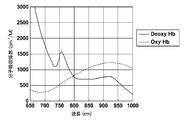
- FIG. 14 shows oxygenated hemoglobin (oxyhemoglobin combined with oxygen: oxy-Hb) abundant in human arteries and deoxygenated hemoglobin (hemoglobin deoxy-Hb not bound to oxygen) abundantly contained in veins.
- the molecular absorption coefficient for each light wavelength is shown.
- the light absorption characteristic of the artery corresponds to that of oxygenated hemoglobin
- the light absorption characteristic of the vein corresponds to that of deoxygenated hemoglobin.
- a photoacoustic image generation method is known in which a difference in optical absorptance according to the wavelength is used to irradiate a blood vessel portion with light of two different wavelengths, and an artery and a vein are distinguished and imaged. (For example, refer to Patent Document 2).
- Patent Documents 3 and 4 describe a variable wavelength laser device capable of emitting light of the two types of wavelengths as described above. These laser devices are alexandrite laser light sources using a flash lamp as an excitation source, and can oscillate at wavelengths of 755 nm and 800 nm.
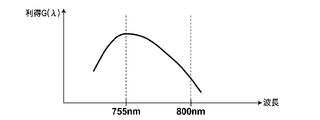
- FIG. 15 is a graph showing the relationship between the oscillation wavelength and luminous efficiency (gain) when alexandrite is used as the laser medium. As can be seen from this graph, for example, the luminous efficiency of alexandrite becomes maximum near the wavelength of 755 nm, and decreases as the wavelength becomes longer in the wavelength range exceeding the wavelength of 755 nm.
- a laser having two oscillation wavelengths having different emission efficiencies for example, a wavelength having a lower emission efficiency is referred to as a “first wavelength” and a wavelength having a higher emission efficiency is referred to as a “second wavelength”).
- first wavelength a wavelength having a lower emission efficiency
- second wavelength a wavelength having a higher emission efficiency
- laser beams having different intensities are oscillated.
- the intensity of the light of the second wavelength may exceed the damage threshold of the apparatus.
- the oscillation wavelength is the second wavelength, it is sufficient if the excitation energy of the laser medium can be reduced in order to reduce the intensity of the light of the second wavelength. There is also a limit to the amount of decrease in excitation energy.
- the present invention has been made in view of the above demands, and in a laser apparatus using a laser medium having two oscillation wavelengths having different emission efficiencies, the intensity of light of each wavelength can be increased without increasing the number of parts of the apparatus. It is an object of the present invention to provide a laser device that can be controlled independently and a photoacoustic measurement device including the laser device.
- the laser device of the present invention is: A solid-state laser medium having an oscillation wavelength at a first wavelength and a second wavelength having higher emission efficiency than the first wavelength; An excitation unit for exciting the laser medium; A first resonator that oscillates light of a first wavelength and has a laser medium on an internal optical path; A second resonator that oscillates light of a second wavelength and has a common optical path that is a common optical path with the first resonator including the optical path in which the laser medium is disposed; A Q value changing unit that includes at least a Q value changing unit disposed on the common optical path, and that Q-oscillates light having the first wavelength or light having the second wavelength; and A control unit for controlling the excitation unit and the Q value changing unit, The control unit When the oscillation wavelength is the first wavelength, the Q value changing unit is controlled when the first delay time has elapsed since the excitation of the laser medium is started, so that the light of the first wavelength is Q-switched, When the oscillation wavelength is the first wavelength,
- the first delay time and the second delay time are set to values at which the intensity of the first wavelength light and the intensity of the second wavelength light are equal to each other. It is preferable.
- the first delay time is set to a value at which the intensity of light of the first wavelength is the maximum possible intensity.
- the control unit changes the set value of the first delay time or the second delay time in accordance with the amount of excitation energy given to the laser medium by the excitation unit.
- the excitation unit includes a flash lamp as a light source, and the control unit changes the set value of the first delay time or the second delay time according to the charging voltage of the flash lamp.
- the control unit has a first reference table in which the charging voltage and the set value of the first delay time or the second delay time are associated with each other, and the first reference table is based on the first reference table. A configuration for changing the set value of the delay time or the second delay time can be employed.
- the excitation unit includes an excitation light source
- the control unit changes the set value of the first delay time or the second delay time according to the use period of the excitation light source.
- the control unit has a second reference table in which the use period and the set value of the first delay time or the second delay time are associated with each other, and the first reference table is based on the second reference table. A configuration in which the set value of the delay time or the second delay time is changed can be employed.
- the first resonator includes a first mirror and a second mirror that are opposed to each other with the laser medium interposed therebetween, and the second resonator includes the first mirror
- the Q medium changing unit includes a laser medium and a third mirror that faces the first mirror across the second mirror
- the Q value changing unit includes a first Q value changing unit disposed on the common optical path, and a second mirror.
- a second Q value changing unit arranged between the third mirror and the third mirror.
- the control unit further includes the resonator length of the first resonator. It is preferable to change the set value of the first delay time according to the above, or change the set value of the second delay time according to the resonator length of the second resonator.
- the control unit includes a third reference table in which the resonator length of the first resonator and the set value of the first delay time are associated, and / or the resonator length of the second resonator and the first resonator length.
- the fourth reference table is associated with the set value of the second delay time, changes the set value of the first delay time based on the third reference table, and based on the fourth reference table It is preferable to change the set value of the second delay time.
- the control unit oscillates the driving states of the first Q value changing unit and the second Q value changing unit, and the Q values of the first resonator and the second resonator oscillate.
- a first driving state in which the Q value is lower than a threshold value a second driving state in which the Q values of the first and second resonators are higher than an oscillation threshold, and
- the first resonator is switched between a third driving state in which the Q value of the first resonator is in a high Q state and the Q value of the second resonator is in a low Q state.
- control unit sets the driving state of the first Q value changing unit and the second Q value changing unit to the first driving state when the laser medium is excited. Further, the control unit changes the driving state of the first Q value changing unit and the second Q value changing unit from the first driving state when the oscillation wavelength is the first wavelength after excitation of the laser medium. It is preferable to switch to the third driving state and switch from the first driving state to the second driving state when the oscillation wavelength is the second wavelength.
- the first Q value changing unit includes a first Q switch that changes the Q value of the first resonator according to the applied voltage
- the second Q value changing unit is A second Q switch that changes the Q value of the second resonator according to the applied voltage
- the control unit controls the first Q value changing unit and the second Q value by controlling the applied voltage. It is preferable to drive the part.
- the photoacoustic measuring device of the present invention includes the laser device described above, And a probe for detecting a photoacoustic wave generated in the subject using laser light emitted from the laser device.
- the photoacoustic measuring device of this invention is provided with the signal processing part which processes the signal of the photoacoustic wave detected using the probe.
- the signal processing unit includes an acoustic image generation unit that generates a photoacoustic image based on a photoacoustic wave signal. It is preferable to generate a reflected acoustic wave image based on the reflected acoustic wave signal transmitted.
- a laser apparatus and a photoacoustic measurement apparatus include a solid laser medium having an oscillation wavelength at a first wavelength and a second wavelength having higher emission efficiency than the first wavelength, an excitation unit, A resonator that oscillates light of a wavelength and has a laser medium on an internal optical path, and a resonator that oscillates light of a second wavelength and has an optical path on which the laser medium is disposed.
- a change unit that controls the excitation unit and the Q value change unit.
- the control unit controls the Q value changing unit when the first delay time has elapsed after the excitation of the laser medium, and switches the light of the first wavelength to the Q switch.
- the Q value is changed when the second delay time elapses when the intensity of light of the second wavelength becomes less than the maximum possible intensity after the excitation of the laser medium is started.
- the unit is controlled to cause the light of the second wavelength to oscillate Q-switch.
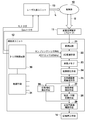
- FIG. 1 is a schematic diagram showing a configuration of a laser apparatus 1 according to the present embodiment.
- the laser device 1 includes a laser rod 51, a flash lamp (excitation lamp) 52, a first mirror 53, a second mirror 54, a third mirror 55, and a first Q value changing unit. 56, a second Q value changing unit 57 and a control circuit 62.
- the first Q value changing unit 56 and the second Q value changing unit 57 as a whole correspond to the Q value changing unit in the present invention.
- the laser device 1 emits laser light L having a plurality of wavelengths including a first wavelength and a second wavelength. For example, in this specification, it is assumed that the gain (luminous efficiency) at the second wavelength for laser oscillation is higher than the gain at the first wavelength.
- the laser rod 51 is a laser medium.
- the laser rod 51 has oscillation wavelengths at 800 nm and 755 nm.
- an alexandrite crystal can be used for the laser rod 51.
- the gain of laser light of alexandrite has a peak around the wavelength of 755 nm.
- the gain monotonously decreases as the wavelength becomes shorter in the wavelength range shorter than the wavelength of 755 nm. Further, the gain monotonously decreases as the wavelength becomes longer in the wavelength range longer than the wavelength of 755 nm.
- the gain of the alexandrite crystal at a wavelength of 800 nm is lower than the gain at a wavelength of 755 nm.
- the molecular absorption coefficient at a wavelength of 755 nm of oxygenated hemoglobin contained in a large amount in a human artery is lower than the molecular absorption coefficient at a wavelength of 800 nm.
- the molecular absorption coefficient at a wavelength of 755 nm of deoxygenated hemoglobin contained in a large amount in veins is higher than the molecular absorption coefficient at a wavelength of 800 nm.
- the photoacoustic signal obtained by irradiating light with a wavelength of 755 nm is relatively large or small with respect to the photoacoustic signal obtained by irradiating light with a wavelength of 800 nm.
- the photoacoustic signal from the artery and the photoacoustic signal from the vein can be discriminated.
- the oxygen saturation can be measured.
- any combination of two wavelengths may be used as long as there is a difference in the light absorption coefficient between the two selected wavelengths, and the above-described about 755 nm and about 800 nm.
- the combination is not limited.
- the two wavelengths selected are about 800 nm (exactly 798 nm) at which the light absorption coefficient is the same between oxygenated hemoglobin and deoxygenated hemoglobin, and the light of deoxygenated hemoglobin.
- a combination with a wavelength of about 755 nm (more precisely, 757 nm) at which the absorption coefficient becomes a maximum value is preferable.
- the first wavelength does not need to be exactly 798 nm.
- the second wavelength does not need to be exactly 757 nm.
- the second wavelength is in the range of 748 to 770 nm which is the half-value width of the peak near the maximum value (757 nm), there is no practical problem.
- the flash lamp 52 is an excitation light source as an excitation unit in the present invention, and irradiates the laser rod 51 with excitation light.
- the flash lamp 52 is driven intermittently.
- the flash lamp 52 is lit in conjunction with a flash lamp trigger transmitted from the control circuit 62.
- a light source other than the flash lamp 52 may be used as the excitation light source.
- the first mirror 53, the second mirror 54, and the third mirror 55 are arranged along the optical axis of the laser rod 51.
- the first mirror 53 and the second mirror 54 face each other with the laser rod 51 interposed therebetween.
- the third mirror 55 is disposed on the side opposite to the laser rod 51 when viewed from the second mirror 54, and faces the first mirror 53 with the laser rod 51 and the second mirror 54 interposed therebetween.
- the first mirror 53 is an output mirror of light having a wavelength of 800 nm and light having a wavelength of 755 nm.
- the reflectance of the first mirror 53 with respect to light with a wavelength of 800 nm is higher than the reflectance with respect to light with a wavelength of 755 nm.
- the reflectance of the first mirror 53 with respect to light with a wavelength of 800 nm is 80%
- the reflectance with respect to light with a wavelength of 755 nm is 70%.
- the second mirror 54 reflects light having a wavelength of 800 nm and transmits light having a wavelength of 755 nm.
- the reflectance of the second mirror 54 with respect to light with a wavelength of 800 nm is 99.8% or more, and the reflectance with respect to light with a wavelength of 755 nm is 0.5% or less.
- the third mirror 55 reflects light having a wavelength of 755 nm.
- the reflectance of the third mirror 55 with respect to light having a wavelength of 755 nm is, for example, 99.8% or more.
- the first mirror 53 and the second mirror 54 constitute a first resonator C1 that oscillates light having a wavelength of 800 nm.
- light having a wavelength of 755 nm emitted from the laser rod 51 passes through the second mirror 54 and is reflected by the third mirror 55, and reciprocates between the first mirror 53 and the third mirror 55.
- the first mirror 53 and the third mirror 55 constitute a second resonator C2 that oscillates light having a wavelength of 755 nm.
- the resonator length of the first resonator C1 is shorter than the resonator length of the second resonator C2.
- the optical path from the first mirror 53 to the second mirror 54 is an optical path common to the first resonator C1 and the second resonator C2, and the laser rod 51 is disposed on this common optical path. .
- the first Q value changing unit 56 is disposed on the common optical path of the first resonator C1 and the second resonator C2, and controls the Q values of the first resonator C1 and the second resonator C2. To do.
- the first Q value changing unit 56 is disposed, for example, between the first mirror 53 and the laser rod 51. Instead, the first Q value changing unit 56 may be disposed between the laser rod 51 and the second mirror 54.
- the first Q value changing unit 56 includes a first Q switch 58 and a polarizer 59.
- the first Q switch 58 changes the Q values of the first resonator C1 and the second resonator C2 according to the applied voltage.
- the first Q switch 58 can be an electro-optic element that changes the polarization state of the light passing therethrough according to the applied voltage.
- a Pockels cell is used for the first Q switch 58.
- the first Q switch 58 sets the first resonator C1 and the second resonator C2 to a low Q state when the applied voltage is the first voltage corresponding to the Q switch off.
- the low Q state refers to a state where the Q value of the resonator is lower than the laser oscillation threshold value.
- the first voltage is a voltage at which the first Q switch 58 functions as a quarter wave plate, for example.
- the first Q switch 58 sets the first resonator C1 and the second resonator C2 to a high Q state when the applied voltage is a second voltage corresponding to the Q switch on.
- the high Q state refers to a state where the Q value of the resonator is higher than the laser oscillation threshold value.
- the absolute value of the second voltage is smaller than the absolute value of the first voltage, and the voltage may be a positive voltage or a negative voltage.
- the second voltage is, for example, 0 V (no voltage applied), and the polarization state of the light transmitted through the first Q switch 58 does not change at this time. Since the voltage at which the Pockels cell works as a quarter wavelength plate varies depending on the wavelength, the second voltage corresponding to the Q switch-on differs between oscillation at a wavelength of 800 nm and oscillation at a wavelength of 755 nm.
- the voltage applied to the Pockels cell differs depending on whether the wavelength is 800 nm or 755 nm. For this reason, in the case of a configuration in which the applied voltage 0 V to the Pockels cell does not correspond to the Q switch on, the control circuit of the Q switch and the control method thereof are somewhat complicated. Therefore, it is preferable that the first Q value changing unit 56 has a configuration in which the applied voltage 0 V corresponds to the Q switch on.
- the polarizer 59 is disposed between the laser rod 51 and the first Q switch 58.
- the polarizer 59 transmits only linearly polarized light in a predetermined direction.
- a beam splitter that transmits linearly polarized light (for example, p-polarized light) in a predetermined direction and reflects a direction orthogonal to the predetermined direction (for example, s-polarized light) can be used.
- the polarizer 59 may be omitted if the light emitted from the laser rod 51 is p-polarized light, such as when an alexandrite crystal is used for the laser rod 51.
- the first Q switch 58 when a first voltage is applied to the first Q switch 58, the first Q switch 58 functions as a quarter wavelength plate. At this time, the p-polarized light incident on the first Q switch 58 from the polarizer 59 becomes circularly polarized light when passing through the first Q switch 58. Thereafter, the light is reflected by the first mirror 53 and enters the first Q switch 58 in the reverse direction. The circularly polarized light incident on the first Q switch 58 in the reverse direction becomes s-polarized light when passing through the first Q switch 58. Thereafter, the light is reflected by a polarizer 59 that reflects s-polarized light and is emitted out of the optical path of the resonator.
- the applied voltage to the first Q switch 58 is 0 V (second voltage)
- the p-polarized light incident on the first Q switch 58 from the polarizer 59 remains as the p-polarized light.
- the light passes through the switch 58 and is reflected by the first mirror 53.
- the p-polarized light reflected by the first mirror 53 passes through the first Q switch 58 as p-polarized light, passes through the polarizer 59 that transmits p-polarized light, and enters the laser rod 51.
- the second Q value changing unit 57 is disposed on the optical path of the second resonator C2 between the second mirror 54 and the third mirror 55, and controls the Q value of the second resonator C2. .
- the second Q value changing unit 57 includes a second Q switch 60 and a quarter wavelength plate 61.
- the second Q switch 60 changes the Q value of the second resonator C2 according to the applied voltage.
- the second Q switch 60 can be an electro-optic element that changes the polarization state of light passing therethrough according to the applied voltage.
- the quarter wavelength plate 61 is disposed between the second Q switch 60 and the third mirror 55.
- a Pockels cell is used for the second Q switch 60.
- the second Q switch 60 sets the second resonator C2 to a low Q state when the applied voltage is the third voltage corresponding to the Q switch off.
- the third voltage is, for example, 0 V (no voltage applied), and at this time, the polarization state of the light transmitted through the second Q switch 60 does not change.
- the second Q switch 60 sets the second resonator C2 to a high Q state when the applied voltage is a fourth voltage corresponding to the Q switch being turned on.
- the absolute value of the fourth voltage is larger than the absolute value of the third voltage, and the voltage may be a positive voltage or a negative voltage.
- the fourth voltage is a voltage at which the second Q switch 60 functions as a quarter wavelength plate, for example.
- the second mirror 54 reflects light having a wavelength of 800 nm and transmits light having a wavelength of 755 nm.
- the light traveling between the second mirror 54 and the third mirror 55 is light having a wavelength of 755 nm, and the light having a wavelength of 800 nm does not travel from the second mirror 54 to the third mirror 55 side.
- the second Q switch 60 functions as a quarter wavelength plate.
- the p-polarized light that has entered the second Q switch 60 through the second mirror 54 from the laser rod 51 side becomes circularly polarized light when passing through the second Q switch 60, and is further a quarter-wave plate.
- the light reflected by the third mirror 55 becomes circularly polarized when passing through the quarter-wave plate 61 in the reverse direction, and further becomes p-polarized when passing through the second Q switch 60, and the laser rod 51.
- the control circuit 62 corresponds to the control unit in the present invention, and drives the first Q value changing unit 56 and the second Q value changing unit 57.
- the control circuit 62 sets the driving states of the first resonator C1 and the second resonator C2 in the first driving state in which the Q values of the resonators are both low Q states lower than the oscillation threshold, A second drive state where both the Q values of the resonators are in a high Q state higher than the oscillation threshold, and the first resonator C1 is in a high Q state and the second resonator C2 is in a low Q state. Switch between the third driving states.
- the control circuit 62 drives the first Q value changing unit 56 by controlling the voltage applied to the first Q switch 58 and controls the second voltage by controlling the voltage applied to the second Q switch 60.
- the Q value changing unit 57 is driven.
- the control circuit 62 transmits a Q switch trigger to the first Q value changing unit and / or the second Q value changing unit, and oscillates the laser beam using the switching of the three driving states.
- the control circuit 62 also drives the flash lamp 52 by transmitting a flash lamp trigger instructing the lighting of the flash lamp 52.
- the first driving state the first voltage is applied to the first Q switch 58, and the first Q switch 58 functions as a quarter wavelength plate.
- the voltage applied to the second Q switch 60 is 0 V (third voltage), and the polarization state of the light passing through the second Q switch 60 does not change. Therefore, the light reflected by the first mirror 53 does not enter the laser rod 51 because the first Q switch 58 functions as a quarter wavelength plate. Further, since the polarization state of the light passing through the second Q switch 60 does not change, the light having a wavelength of 755 nm reflected by the third mirror 55 enters the laser rod 51 as s-polarized light.
- the first resonator C1 and the second resonator C2 are in a low Q state, and laser oscillation does not occur for both the wavelength 800 nm and the wavelength 755 nm.
- the first Q switch 58 is disposed on the common optical path, and the second resonator C2 can be brought into a low Q state by applying a first voltage to the first Q switch 58.
- the voltage applied to the second Q switch 60 is not particularly limited to the third voltage
- the fourth voltage is applied to the second Q switch 60
- the second voltage The Q switch 60 may be used as a quarter wavelength plate.
- the voltage applied to the first Q switch 58 is 0 V (second voltage), and the polarization state of the light passing through the first Q switch 58 does not change.
- the fourth voltage is applied to the second Q switch 60, and the second Q switch 60 functions as a quarter wavelength plate. Accordingly, since the polarization state of the light passing through the first Q switch 58 does not change, the light reflected by the first mirror 53 enters the laser rod 51 as p-polarized light. Further, since the second Q switch 60 functions as a quarter wavelength plate, light having a wavelength of 755 nm reflected by the third mirror 55 enters the laser rod 51 as p-polarized light.
- the first resonator C1 and the second resonator C2 are in a high Q state, and laser oscillation occurs.
- the gain at the wavelength of 755 nm is higher than the gain at the wavelength of 800 nm, so the oscillation wavelength is 755 nm, which has a higher gain.
- the voltage applied to the first Q switch 58 is 0 V (second voltage), and the polarization state of the light passing through the first Q switch 58 does not change.
- the voltage applied to the second Q switch 60 is 0 V (third voltage), and the polarization state of the light passing through the second Q switch 60 is not changed. Since the polarization state of the light passing through the first Q switch 58 does not change, the light reflected by the first mirror 53 enters the laser rod 51 as p-polarized light. Further, since the polarization state of the light passing through the second Q switch 60 does not change, the light having a wavelength of 755 nm reflected by the third mirror 55 enters the laser rod 51 as s-polarized light.
- the first resonator C1 is in a high Q state and the second resonator C2 is in a low Q state, and laser oscillation occurs in the first resonator C1.
- the first resonator C1 is a resonator having a wavelength of 800 nm, and the oscillation wavelength is 800 nm.
- the control circuit 62 sets the driving state of the first Q value changing unit 56 and the second Q value changing unit 57 to the first driving state when the laser rod 51 is excited. That is, the flash lamp 52 is lit while the first resonator C1 and the second resonator C2 are in the low Q state, and the laser rod 51 is excited.
- the control circuit 62 changes the driving state of the first Q value changing unit 56 and the second Q value changing unit 57 from the first driving state to the first driving state. 3 is switched to the driving state.
- the oscillation wavelength is 800 nm.
- the control circuit 62 changes the driving state of the first Q value changing unit 56 and the second Q value changing unit 57 from the first driving state to the first driving state.
- the driving state is switched to 2.
- the control circuit 62 drives the second Q value changing unit 57 so that the second resonator C2 is in the high Q state, and at the same time, the first resonator is in the high Q state.
- the Q value changing unit 56 is driven.
- the control circuit 62 drives the second Q value changing unit 57 so that the second resonator C2 is in the high Q state, and then the first Q is set so that the first resonator is in the high Q state.
- the value changing unit 56 may be driven.
- both resonators are in the high Q state, but the oscillation wavelength is 755 nm, which has a high gain between the wavelength of 800 nm and the wavelength of 755 nm.
- the Q-switch oscillation of the light is realized by driving the second Q value changing unit 57, in this case, the drive instruction to the second Q value changing unit 57 by the control circuit 62 becomes the Q switch trigger. .
- the control circuit 62 has a delay time set for each wavelength with respect to the time (delay time) from when the excitation of the laser medium is started until the light Q-oscillates, and according to each delay time, The light is oscillated by Q switch. More specifically, when the oscillation wavelength is the first wavelength (in this embodiment, the wavelength is 800 nm), the control circuit 62 performs the first delay when the first delay time elapses after the excitation of the laser rod 51 is started.
- the Q value changing unit 56 and the second Q value changing unit 57 are controlled to cause the light of the first wavelength to perform Q-switch oscillation, and the oscillation wavelength is the second wavelength (a wavelength of 755 nm in the present embodiment).
- the intensity of the light of the second wavelength is less than the maximum possible intensity (for example, 90%, 80%, or 50% of the maximum possible intensity)
- the first Q value changing unit 56 and the second Q value changing unit 57 are controlled to cause the light of the second wavelength to oscillate Q-switch.
- the maximum possible intensity refers to the maximum intensity of light that can be output as a potential capacity when a laser medium is excited with a certain excitation energy.
- FIG. 2 is a graph showing the relationship between the excitation energy and the pulse width of the laser beam for each resonator length.
- the figure shows the relationship between the excitation energy and the pulse width for two resonator lengths.
- Graph (a) shows the relationship between excitation energy and pulse width when a resonator with a short resonator length is used
- graph (b) shows excitation energy and pulse width when a resonator with a long resonator length is used. Shows the relationship. Referring to graphs (a) and (b), it can be seen that, when the excitation energy is constant, the pulse width can be shortened when the resonator length is shorter than when the resonator length is long.
- the pulse width of the pulsed laser light with a wavelength of 800 nm is shorter than the pulse width of the pulsed laser light with a wavelength of 755 nm. it can.
- FIG. 3 is a graph showing the relationship between excitation energy and laser light intensity for each resonator length.
- the figure shows the relationship between the excitation energy and the intensity of the laser beam for two resonator lengths.
- Graph (a) shows the relationship between excitation energy and intensity when a resonator with a short resonator length is used
- graph (b) shows the relationship between excitation energy and intensity when a resonator with a long resonator length is used. Show the relationship. Referring to graphs (a) and (b), it can be seen that when the excitation energy is constant, the laser output can be increased when the resonator length is shorter than when the resonator length is longer.
- the first resonator C ⁇ b> 1 has a shorter resonator length than the second resonator C ⁇ b> 2, and the laser output of light having a wavelength of 800 nm compared to the case where both resonators have the same resonator length. Can be raised.
- FIG. 4 is a graph showing the relationship between the excitation energy and the pulse width of the laser beam for each mirror reflectance.
- graph (a) shows the relationship between excitation energy and pulse width when the reflectance of the first mirror 53 as an output mirror is 80%
- graph (b) shows the first mirror 53.
- the relationship between the excitation energy and the pulse width when the reflectivity is 60% is shown. Referring to graphs (a) and (b), when the excitation energy is constant, it can be seen that the higher the output mirror reflectivity, the shorter the pulse width compared to the lower output mirror reflectivity. .
- the pulse width of the pulsed laser light with a wavelength of 800 nm is made larger than the pulse width of the pulsed laser light with a wavelength of 755 nm. Can also be shortened.
- FIG. 5 is a graph showing the relationship between excitation energy and laser light intensity for each mirror reflectance.
- graph (a) shows the relationship between excitation energy and intensity when the reflectance of the first mirror 53 is 80%
- graph (b) shows the reflectance of the first mirror 53 at 60. The relationship between excitation energy and intensity in the case of% is shown. Referring to graphs (a) and (b), when the excitation energy is constant, the higher the output mirror reflectivity, the higher the laser output compared to the lower output mirror reflectivity. I understand.
- the laser of light with a wavelength of 800 nm is compared with the case where the reflectances of both wavelengths are the same.
- the output can be increased.
- FIG. 6 is a graph showing the relationship between excitation energy and laser light intensity for each oscillation wavelength.
- X in FIG. 6 is a graph relating to light of the first wavelength having a low gain
- Y in FIG. 6 is a graph relating to light of the second wavelength having a high gain.
- FIG. 6A when the laser rod 51 is excited with the same excitation energy E 0 , if the excitation energy is increased in order to secure the intensity I 1 of the light of the first wavelength, the second In some cases, the intensity I 2 of the light having the wavelength exceeds the damage threshold I th of the lens, mirror, etc. in the laser device 1.
- the present inventors have found a method of reducing the gain of only the light of the second wavelength by setting the delay time, and shifting the graph Y to the left as shown in FIG. 6B. According to this method, it is possible to reduce the light intensity I 2 of the second wavelength to less than the damage threshold I th without reducing the light intensity I 1 of the first wavelength.
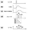
- FIG. 7 is a timing chart showing the relationship between the delay time and the intensity of the laser beam.
- 7A shows the timing of the flash lamp (FL) trigger
- FIG. 7B shows the time change of the emission intensity of the flash lamp
- FIG. 7C shows the time change of the inversion distribution state density in the laser rod.
- (d) shows the timing of the Q switch (Qsw) trigger
- (e) shows the pulse laser beam output corresponding to each timing of the Q switch trigger. That is, in (d) and (e), when the Q switch trigger is output at the timing T1 of the delay time D1, the pulse laser beam P1 is output, and when the Q switch trigger is output at the timing T2 of the delay time D2.
- the pulse laser beam P2 When the pulse laser beam P2 is output and the Q switch trigger is output at the timing T3 of the delay time D3, the pulse laser beam P3 is output, and the Q switch trigger is output at the timing T4 of the delay time D4 Indicates that the pulsed laser beam P4 is output.
- the flash lamp when a flash lamp trigger is transmitted from the control circuit 62, the flash lamp emits light in conjunction with it.
- the light emission intensity of the flash lamp increases for a while after the light emission, and starts to decrease after reaching a peak at a certain time.
- an inversion distribution is formed according to the amount of light absorbed, so the density of states of the inversion distribution also increases with the passage of time. It decreases gradually and then decreases greatly. That is, since the density of states of the inversion distribution changes with time, the intensity of the laser oscillation light varies depending on the timing at which the Q switch trigger is issued. For example, in FIG.
- the pulse laser beam P2 having the maximum intensity is obtained at the timing T2 when the inversion distribution state density is the highest, and the intensity of the pulse laser beam (P1 ⁇ P4) as the inversion distribution state density becomes smaller.
- ⁇ P3) is decreasing. That is, the delay time D2 is a delay time at which the light intensity is the maximum possible intensity, and the delay times D1, D3, and D4 are delay times at which the light intensity is less than the maximum possible intensity. Generally, the delay time D2 is about 150 to 200 ⁇ s.
- the time difference between adjacent Q switch triggers (that is, the difference between the delay times D1 and D2, the difference between the delay times D2 and D3, and the delay times D3 and D4).
- FIG. 8 is a graph showing how the relationship between excitation energy and laser light intensity changes according to the delay time.
- D10 to D40 are graphs showing the intensity of light of the second wavelength
- X is a graph showing the intensity of light of the first wavelength.
- D10 is a graph showing the light intensity at the delay time D1
- D20 is a graph showing the light intensity at the delay time D2
- D30 is the light intensity at the delay time D3.
- D40 is a graph showing the light intensity at the delay time D4.
- the graph of D20 is a graph which gives the maximum intensity
- the intensity I2 of the second wavelength light can be controlled within a range less than the maximum possible intensity. , it is possible to lower further below the damage threshold I th.
- the second wavelength must always have a higher gain than the first wavelength in order to enable wavelength switching. Therefore, the oscillation threshold excitation energy E 2 for the second wavelength is set the delay time to be smaller than the oscillation threshold excitation energy E 1 for the first wavelength.
- the excitation energy is lowered in the normal setting (for example, the delay time D2) because the excitation energy has the lower limit E min even if the intensity of light of each wavelength is made uniform.
- the intensity of light of each wavelength may not be uniform. Therefore, even in such a case, for example, if the setting of the delay time is changed from D2 to D4, the intensities I 1 and I 2 of the light of each wavelength can be made equal with the excitation energies E 3 and E 0 equal to or higher than E min it can.
- the fact that the intensities of the light of each wavelength are equal or equal means that the difference in intensity of the light of each wavelength is within 10% based on the light intensity of the first wavelength.
- the setting of the delay time related to the oscillation of the light of the second wavelength has been described. However, the setting of the delay time related to the oscillation of the light of the first wavelength may be changed.
- FIG. 9 is a timing chart regarding the emission of the excitation lamp, the voltage applied to the Q switch, and the output of the laser beam.
- the control circuit 62 transmits a flash lamp (excitation lamp) trigger to turn on the flash lamp 52 at time t1 (a).
- the control circuit 62 applies the first voltage to the first Q switch 58 (Q-sw1) before the flash lamp 52 is lit (b), and applies the first voltage to the second Q switch 60 (Q-sw2).
- the applied voltage is set to 0 V (third voltage) (c).
- the time for applying the first voltage to the first Q switch 58 may be a time slightly before the time t1.
- the first voltage may be continuously applied to the first Q switch 58 after the previous pulse laser beam emission.
- the first Q switch 58 functions as a quarter wavelength plate.
- the second Q switch 60 by not applying a voltage to the second Q switch 60, the polarization state of the light passing through the second Q switch 60 does not change.
- the laser rod 51 When the laser rod 51 is excited at time t1, p-polarized light is emitted from the laser rod 51.
- the light emitted from the laser rod 51 in the direction of the first mirror 53 reciprocates through the first Q switch 58 functioning as a quarter-wave plate, the polarization direction is rotated by 90 °, and passes through the polarizer 59. Cannot be returned to the laser rod 51.
- the light having a wavelength of 755 nm has a predetermined polarization axis because the polarization direction rotates 90 ° by reciprocating the quarter-wave plate 61. It does not contribute to the laser oscillation of the laser rod 51. Therefore, the Q values of the first resonator C1 and the second resonator C2 are in a low Q state, and the first resonator C1 and the second resonator C2 do not oscillate.
- the control circuit 62 transmits an instruction to change the applied voltage of the first Q switch 58 as a Q switch trigger, and the applied voltage to the first Q switch 58 at time t2 when the delay time Dx has elapsed from time t1. Is changed from the first voltage to 0 V (second voltage) (b). At this time, the control circuit 62 does not change the voltage applied to the second Q switch 60 at 0 V (c). By changing the voltage applied to the first Q switch 58 to 0V, the Q value of the first resonator C1 changes from the low Q state to the high Q state. On the other hand, the Q value of the second resonator C2 is kept in the low Q state.
- the delay time Dx is a delay time set for oscillation of light with a wavelength of 800 nm, and is set so that, for example, the intensity of light with a wavelength of 800 nm having a low gain becomes the maximum possible intensity.
- the control circuit 62 transmits a flash lamp trigger after emitting pulsed laser light having a wavelength of 800 nm, and turns on the flash lamp 52 at time t3 (a).
- the control circuit 62 applies the first voltage to the first Q switch 58 at a time before time t3 (b), and the Q values of the first resonator C1 and the second resonator C2 are Low Q state.
- the control circuit 62 changes the applied voltage of the first Q switch 58 from the first voltage to 0 V at time t4 when the delay time Dy has elapsed from time t3, and changes the applied voltage of the second Q switch 60 from 0 V. Change to the fourth voltage.
- the applied voltage of the first Q switch 58 and the applied voltage of the second Q switch 60 are changed simultaneously, or the applied voltage of the second Q switch 60 is changed first and then the first Q switch 58
- the delay time Dy is a delay time set independently of the delay time Dx for the oscillation of light having a wavelength of 755 nm.
- the intensity of light having a high gain of 755 nm is less than the maximum possible intensity and the wavelength It is set to be equal to the intensity of light of 800 nm.
- the first Q value changing unit 56 and the second Q value changing unit 57 need only be able to switch between the three states of the first, second, and third driving states, and the first Q value changing unit.
- the specific configurations of 56 and the second Q value changing unit 57 are not limited to those described above.
- the first Q value changing unit 56 may be configured by combining a Pockels cell and a quarter-wave plate in the same manner as the second Q value changing unit 57, or the second Q value changing unit 57 may be Similarly to the first Q value changing unit 56, a Pockels cell and a polarizer may be combined.
- control circuit 62 automatically changes the set values of the respective delay times set for the oscillation of the light having the first wavelength or the second wavelength in accordance with the amount of excitation energy that the flash lamp 52 gives to the laser rod 51. Configuration can be adopted. Thereby, for example, when the target intensity of the output light is determined and the excitation energy must be changed or the excitation energy is not stable, the control circuit 62 changes the excitation energy. If the set value of the delay time is changed so as to cancel out the above, it becomes easy to maintain the target strength. For example, when the excitation light source is the flash lamp 52, the control circuit 62 changes the set value of each delay time according to the charging voltage of the flash lamp based on the relationship between the charging voltage of the flash lamp 52 and the excitation energy amount.
- the control circuit 62 may have a reference table (first reference table) in which the charging voltage is associated with the first or second delay time setting value (or its change amount). , They may have a relational expression associated with them.
- the control circuit 62 measures the charging voltage or reads the setting value of the charging voltage to acquire the value of the charging voltage, and refers to the first reference table to correspond to the first charging voltage corresponding to the acquired charging voltage.
- the setting value (or change amount thereof) of the second delay time is read, and the read setting value is newly set to the first or second delay time (or the read change amount is set to the first or second delay). Applies to time settings).
- control circuit 62 changes the set value of each delay time according to the use period of the excitation light source based on the relationship between the use period (including the use time) of the excitation light source such as the flash lamp 52 and the excitation energy amount. You can also.
- the control circuit 62 may have a reference table (second reference table) in which the use period and the set value (or the amount of change) of the first or second delay time are associated with each other. , They may have a relational expression associated with them.
- control circuit 62 measures the use period and obtains the length thereof, and refers to the second reference table to set the first or second delay time set value corresponding to the obtained use period ( Alternatively, the change amount) is read, and the read set value is newly set to the first or second delay time (or the read change amount is applied to the first or second delay time set value).
- At least one of the first mirror 53, the second mirror 54, and the third mirror 55 may be movable along the optical axis direction.
- the relative distance between the mirrors can be adjusted, and the resonator length of the first resonator C1 and the second resonator can be adjusted.
- the resonator length of C2 can be changed.
- the pulse width of the pulse laser beam having a wavelength of 800 nm and the pulse width of the pulse laser beam having a wavelength of 755 nm are changed. At least one of them can be changed.
- the control circuit 62 includes a reference table (third reference table) in which the resonator length of the first resonator C1 and the set value (or the amount of change) of the delay time Dx are associated with each other.
- a reference table fourth reference table in which the resonator length of the second resonator C2 and the set value (or the amount of change) of the delay time Dy are associated with each other. You may have a relational expression.
- control circuit 62 acquires the resonator length of each resonator from the amount of movement of each mirror, and refers to the third and / or fourth reference table to correspond to the first resonator length corresponding to the acquired resonator length.
- the setting value (or change amount thereof) of the second delay time is read, and the read setting value is newly set to the first or second delay time (or the read change amount is set to the first or second delay). Applies to time settings).
- the laser apparatus 1 is a solid laser medium having an oscillation wavelength at the first wavelength (800 nm) and the second wavelength (755 nm) having higher emission efficiency than the first wavelength.
- a Q-value changing unit (first Q-value changing unit 56 and second Q-value changing unit 57) that includes a changing unit and Q-switch oscillates light of the first or second wavelength, and an excitation unit and a Q-value change
- a control unit for controlling the unit.
- the Q value is changed when the second delay time elapses when the intensity of light of the second wavelength becomes less than the maximum possible intensity after the excitation of the laser medium is started.
- the unit is controlled to cause the light of the second wavelength to oscillate Q-switch. That is, in the laser device 1, the delay time Dx when oscillating the light of the first wavelength and the delay time Dy when oscillating the light of the second wavelength are set independently of each other. As a result, in a laser device using a laser medium having two oscillation wavelengths with different emission efficiencies, the light intensity of each wavelength can be controlled independently by adjusting these delay times without increasing the number of parts of the device. It becomes possible.
- the first mirror 53 and the second mirror 54 constitute a first resonator C1 that oscillates light having a wavelength of 800 nm, and the first mirror 53 and the third mirror 55 A second resonator C2 that oscillates light having a wavelength of 755 nm is configured.
- the laser rod 51 has oscillation wavelengths at a wavelength of 800 nm and a wavelength of 755 nm, and the light emission efficiency at the wavelength 755 nm is higher than the light emission efficiency at the wavelength 800 nm.
- the first Q value changing unit 56 is disposed in a common part to the first resonator C1 and the second resonator C2, and the second Q is changed between the second mirror 54 and the third mirror 55.
- a value changing unit 57 is arranged.
- the Q values of the first resonator C1 and the second resonator C2 can be controlled. Further, by driving the second Q value changing unit 57, only the Q value of the second resonator C2 can be controlled.
- the first Q switch 58 is inserted into the first resonator C1 for a wavelength of 800 nm with a low gain.
- the first Q switch 58 and the second Q switch 60 are inserted into the second resonator C2 for the wavelength 755 nm having a high gain.
- Patent Document 3 two Pockels cells are inserted in the resonators of both wavelengths, and a decrease in output becomes a problem particularly at a wavelength of 800 nm where the gain is low.
- only one Pockels cell is inserted into the first resonator C1, and it is not necessary to arrange a plurality of elements that change the polarization state of light in the first resonator C1, For a wavelength of 800 nm where the laser output is low, it is possible to suppress a decrease in laser output due to the insertion of a plurality of Pockels cells.
- the first resonator C1 and the second resonator C2 are configured on one axis so that the optical axes of the light having a wavelength of 800 nm and the light having a wavelength of 755 nm are parallel to each other.
- the optical member of a mirror and a Q value change part can be used in common with the light of wavelength 800nm and the light of wavelength 755nm.
- the third mirror 55 is arranged on the side farther from the laser rod 51 than the second mirror 54, and the resonator length of the first resonator C1 is the second resonator C2. Shorter than the resonator length. By shortening the resonator length of the first resonator C1, the pulse laser beam can be shortened at a wavelength of 800 nm where the gain is low.
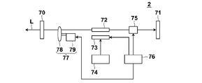
- FIG. 10 is a schematic diagram showing the configuration of the laser apparatus 2 according to the second embodiment.
- the laser apparatus 2 according to the present embodiment has a wavelength selection unit including a plurality of bandpass filters having different transmission wavelengths in the resonator, and selects a wavelength to be oscillated by the wavelength selection unit.
- the laser device 2 includes two mirrors 70 and 71 constituting a resonator, a laser rod 72, a flash lamp 73, a power supply circuit 74, a Q switch 75, a control circuit 76, and a wavelength selection unit 77.
- the laser rod 72 is a laser medium, and as the laser rod 72, for example, an alexandrite crystal can be used as in the first embodiment. Also in this embodiment, for example, the first wavelength with a low gain is 800 nm, and the second wavelength with a high gain is 755 nm.
- the flash lamp 73 is an excitation light source to which a power supply circuit 74 is connected, and irradiates the laser rod 72 with excitation light. A light source other than the flash lamp 73 may be used as the excitation light source.
- the mirrors 70 and 71 are opposed to each other with the laser rod 72 interposed therebetween, and these mirrors constitute a resonator.
- this resonator corresponds to both the first and second wavelengths.
- this resonator oscillates light of both the first and second wavelengths.
- the mirror 70 is the output side.
- a Q switch 75 and a wavelength selector 77 are arranged on the optical path in the resonator. The Q value of the resonator is changed by the Q switch 75.
- a Pockels cell can be used as the Q switch.
- the wavelength selector 77 is used when switching the oscillation wavelength between the first wavelength and the second wavelength.
- the wavelength selection unit 77 includes a plurality of band pass filters (BPFs) 78 having different transmission wavelengths and a drive unit 79 that rotationally drives the band pass filter 78.
- BPFs band pass filters
- the wavelength selector 77 selectively inserts a specific bandpass filter among the plurality of bandpass filters 78 on the optical path of the resonator.
- the wavelength selector 77 includes, for example, a first bandpass filter that transmits light having a center wavelength of 755 nm, and a second bandpass filter that transmits light having a center wavelength of 800 nm.
- the first and second band-pass filters are composed of rotating bodies arranged in an angular range of 0 ° to 180 ° and an angular range of 180 ° to 360 °, for example, and are transmitted along with rotational displacement.
- the light to be changed is configured to change.
- the oscillation wavelength can be set to 755 nm by inserting the first band pass filter on the optical path of the resonator while rotating the rotating body, and the second band pass filter can be set on the optical path of the resonator. By inserting, the oscillation wavelength can be set to 800 nm.
- the driving unit 79 rotationally drives a plurality of bandpass filters 78 formed of a rotating body so that the bandpass filters inserted on the optical path of the resonator are sequentially switched. Further, the rotation state indicating which band pass filter is on the optical path is detected by, for example, a rotary encoder (not shown).
- the control circuit 76 transmits a flash lamp trigger for controlling the light emission of the flash lamp 73, and irradiates the laser rod 72 with the excitation light from the flash lamp 73.
- the control circuit 76 monitors the state of the BPF and transmits a flash lamp trigger based on the state. For example, the control circuit 76 determines that the BPF state is a delay time from the excitation of the laser medium to the Q-switch oscillation from the driving position of the rotating body where the bandpass filter corresponding to the wavelength of the light to be emitted is inserted in the optical path.
- a flash lamp trigger is transmitted when the amount of displacement of the rotating body is subtracted during this period. This delay time is set for each wavelength of light to be emitted.
- the delay time for the wavelength of 800 nm is set so that the light intensity becomes the maximum possible intensity
- the delay time for the wavelength 755 nm is set so that the light intensity is less than the maximum possible intensity.
- the control circuit 76 transmits a Q switch trigger to the Q switch 75 when a delay time set for each wavelength of light to be emitted elapses. Light is output from the mirror 70 on the output side when the Q switch 75 suddenly changes the resonator from the low Q state to the high Q state in response to the Q switch trigger (by turning on the Q switch).
- the laser apparatus 2 is a solid laser medium having an oscillation wavelength at the first wavelength (800 nm) and the second wavelength (755 nm) having higher emission efficiency than the first wavelength.
- Laser rod 72 excitation unit (flash lamp 73), and first resonator (mirrors 70 and 71) that oscillates light of the first wavelength and has a laser medium on the internal optical path.
- a second resonator (mirrors 70 and 71) that oscillates light of the second wavelength and has a common optical path with the first resonator including the optical path in which the laser medium is disposed;
- a Q value changing unit (Q switch 75) that includes at least a Q value changing unit disposed on the common optical path and Q-oscillates light having the first or second wavelength, and controls the excitation unit and the Q value changing unit.
- Control unit (control circuit 76) Obtain. Then, when the oscillation wavelength is the first wavelength, the control unit controls the Q value changing unit when the first delay time has elapsed after the excitation of the laser medium, and switches the light of the first wavelength to the Q switch.
- the Q value is changed when the second delay time elapses when the intensity of light of the second wavelength becomes less than the maximum possible intensity after the excitation of the laser medium is started.
- the unit is controlled to cause the light of the second wavelength to oscillate Q-switch. That is, in the laser device 2, the delay time when oscillating the light of the first wavelength and the delay time when oscillating the light of the second wavelength are set independently of each other. As a result, in a laser device using a laser medium having two oscillation wavelengths with different emission efficiencies, the light intensity of each wavelength can be controlled independently by adjusting these delay times without increasing the number of parts of the device. It becomes possible.
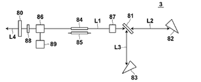
- FIG. 11 is a schematic diagram illustrating a configuration of a laser apparatus 3 according to the third embodiment.
- the laser device 3 according to the present embodiment oscillates at a plurality of wavelengths using a branching polarizer and a resonant optical path selector.
- the laser device 3 includes an output side mirror 80, a polarizer 81, a first reflecting prism 82, a second reflecting prism 83, a laser rod 84, a flash lamp 85, two Pockels cells 86 and 87, ⁇ / 4 wavelength plate 88 and trigger controller 89.
- a laser rod 84 and a flash lamp 85 are arranged between the mirror 80 and the polarizer 81.
- the laser rod 84 is a laser medium, and as the laser rod 84, for example, an alexandrite crystal can be used as in the first embodiment. Also in this embodiment, for example, the first wavelength with a low gain is 800 nm, and the second wavelength with a high gain is 755 nm.
- the flash lamp 85 is an excitation light source, and irradiates the laser rod 84 with excitation light in conjunction with the flash lamp trigger transmitted from the control circuit 89. A light source other than the flash lamp 85 may be used as the excitation light source.
- a Pockels cell 87 constituting a resonance optical path selection unit is disposed.
- the Pockels cell 87 is applied with a voltage for rotating the polarization direction of the incident linearly polarized light by 90 ° when oscillating at a wavelength of 800 nm, and is not applied when oscillating at a wavelength of 755 nm.
- a polarizer 81 which is an optical path branching unit transmits p-polarized light and reflects s-polarized light. The light transmitted through the polarizer 81 travels along the first branch optical path L2 and is reflected by the first reflecting prism 82. On the other hand, the light reflected by the polarizer 81 travels along the second branch optical path L3 and is reflected by the second reflecting prism 83.
- the first reflecting prism 82 is arranged to have a Brewster angle with respect to the incident light.
- the first reflecting prism 82 has a dielectric reflecting film that selectively reflects light having a wavelength of 755 nm.
- the second reflecting prism 83 has a dielectric reflecting film that selectively reflects light having a wavelength of 800 nm.
- the mirror 80 and the second reflecting prism 83 constitute a resonator (first resonator) having a wavelength of 800 nm.
- the mirror 80 and the first reflecting prism 82 constitute a resonator (second resonator) having a wavelength of 755 nm. These resonators have a common optical path L1.
- a Q switch composed of a Pockels cell 86 and a ⁇ / 4 wavelength plate 88 is also arranged on the common optical path L1.
- the voltage applied to the Pockels cell 86 is controlled by the control circuit 89.
- the flash lamp 85 When the flash lamp 85 is turned on, no voltage is applied to the Pockels cell 86 constituting the Q switch, and the Q switch is off.
- the Q switch After the flash lamp 85 is turned on, the Q switch is turned on when a predetermined delay time elapses. Thereby, laser oscillation occurs in the first resonator or the second resonator according to the state of the Pockels cell 87, and light is output from the mirror 80.
- the delay time is set for each wavelength of light to be emitted. For example, the delay time for the wavelength of 800 nm is set so that the light intensity becomes the maximum possible intensity, and the delay time for the wavelength 755 nm is set so that the light intensity is less than the maximum possible intensity.
- the p-polarized light emitted from the laser rod 84 passes through the Pockels cell 87 as p-polarized light and transmits the p-polarized light 81. , Passes through the first branch optical path L2, and is reflected by the first reflecting prism 82.
- the light reflected by the first reflecting prism 82 passes through the polarizer 81 and the Pockels cell 87 in the opposite direction as p-polarized light, enters the laser rod 84, causes laser oscillation, and outputs laser light L4.
- the first reflecting prism 82 selectively reflects light having a wavelength of 755 nm, so that light having a wavelength of 755 nm oscillates.
- the p-polarized light emitted from the laser rod 84 is rotated by 90 ° when the polarization direction is transmitted through the Pockels cell 87. It becomes polarized light.
- the s-polarized light is reflected by the polarizer 81, passes through the second branch optical path L3, and is reflected by the second reflecting prism 83.
- the light reflected by the second reflecting prism 83 passes through the polarizer 81 in the reverse direction and enters the Pockels cell 87 in the reverse direction.
- the light that has entered the Pockels cell 87 with s-polarized light has its polarization direction rotated by 90 ° when passing through the Pockels cell 87, becomes p-polarized light, and enters the laser rod 84, causing laser oscillation, and the laser light L4 is generated. Is output.
- the second reflecting prism 83 selectively reflects light having a wavelength of 800 nm, so that light having a wavelength of 800 nm oscillates.
- the laser apparatus 3 is a solid laser medium having an oscillation wavelength at the first wavelength (800 nm) and the second wavelength (755 nm) having higher emission efficiency than the first wavelength.
- Laser rod 84 excitation unit (flash lamp 85), and first resonator that oscillates light of the first wavelength and has a laser medium on the internal optical path (mirror 80 and reflecting prism) 83) and a second resonator (mirror 80 and reflecting prism) having a common optical path with the first resonator including the optical path in which the laser medium is disposed, the resonator oscillating light of the second wavelength.
- a Q-value changing unit (Q switch 86) that includes at least a Q-value changing unit disposed on the common optical path, Q-oscillates light of the first or second wavelength, a pumping unit, and a Q-value changing Control system Parts and a (control circuit 89). Then, when the oscillation wavelength is the first wavelength, the control unit controls the Q value changing unit when the first delay time has elapsed after the excitation of the laser medium, and switches the light of the first wavelength to the Q switch. When oscillation is performed and the oscillation wavelength is the second wavelength, the Q value is changed when the second delay time elapses when the intensity of light of the second wavelength becomes less than the maximum possible intensity after the excitation of the laser medium is started.
- the unit is controlled to cause the light of the second wavelength to oscillate Q-switch. That is, in the laser device 3, the delay time for oscillating the light of the first wavelength and the delay time for oscillating the light of the second wavelength are set independently of each other. As a result, in a laser device using a laser medium having two oscillation wavelengths with different emission efficiencies, the light intensity of each wavelength can be controlled independently by adjusting these delay times without increasing the number of parts of the device. It becomes possible.
- control unit sets each delay time set for the oscillation of light of the first wavelength or the second wavelength according to the excitation energy amount and the resonator length. It is possible to adopt a configuration that automatically changes.
- FIG. 12 is a schematic diagram illustrating a configuration of the photoacoustic measurement apparatus 10 according to the embodiment.
- the photoacoustic measuring device 10 includes an ultrasonic probe (probe) 11, an ultrasonic unit 12, and a laser light source unit 13 including the laser device of the present invention.
- the laser light source unit 13 emits pulsed laser light that irradiates the subject.
- the laser light source unit 13 emits laser light having a plurality of wavelengths including the first wavelength and the second wavelength.
- the laser light source unit 13 includes, for example, the laser device 1 according to the first embodiment and a light guide unit (for example, an optical fiber) that guides the laser light emitted from the laser device 1.
- the laser light emitted from the laser light source unit 13 is guided to the probe 11 using the light guide means, and is irradiated from the probe 11 toward the subject.
- the irradiation position of the laser beam is not particularly limited, and the laser beam may be irradiated from a place other than the probe 11.
- an ultrasonic wave photoacoustic wave
- the probe 11 includes an ultrasonic detector.
- the probe 11 has, for example, a plurality of ultrasonic detector elements (ultrasonic transducers) arranged in a one-dimensional manner, and an acoustic wave (light) from within the subject by the ultrasonic transducers arranged in a one-dimensional manner. Sound signal).
- ultrasonic detector elements ultrasonic transducers
- acoustic wave light
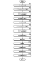
- the ultrasonic unit 12 includes a reception circuit 21, an AD conversion unit 22, a reception memory 23, a complex number conversion unit 24, a photoacoustic image reconstruction unit 25, a phase information extraction unit 26, an intensity information extraction unit 27, and a detection / logarithmic conversion unit 28. , A photoacoustic image construction means 29, a trigger control circuit 30, and a control means 31.
- the receiving circuit 21 receives the photoacoustic signal detected by the probe 11.
- the AD conversion unit 22 is a detection unit that samples the photoacoustic signal received by the receiving circuit 21 and generates photoacoustic data that is digital data.
- the AD conversion means 22 samples the photoacoustic signal at a predetermined sampling period in synchronization with the AD clock signal.
- the AD conversion means 22 stores the photoacoustic data in the reception memory 23.
- the AD conversion means 22 stores photoacoustic data corresponding to each wavelength of the pulsed laser light emitted from the laser light source unit 13 in the reception memory 23. That is, the AD conversion means 22 has the first photoacoustic data obtained by sampling the photoacoustic signal detected by the probe 11 when the subject is irradiated with the pulse laser beam having the first wavelength, and the second wavelength.
- the second photoacoustic data obtained by sampling the photoacoustic signal detected by the probe 11 when the pulse laser beam is irradiated is stored in the reception memory 23.
- the complex number conversion means 24 reads the first photoacoustic data and the second photoacoustic data from the reception memory 23, and generates complex number data in which one is a real part and the other is an imaginary part. In the following description, it is assumed that the complex number converting means 24 generates complex number data having the first photoacoustic data as an imaginary part and the second photoacoustic data as a real part.
- the photoacoustic image reconstruction unit 25 inputs complex number data from the complex number conversion unit 24.
- the photoacoustic image reconstruction means 25 performs image reconstruction from the input complex number data by the Fourier transform method (FTA method).
- FFA method Fourier transform method
- For image reconstruction by the Fourier transform method for example, a conventionally known method described in the document “Photoacoustic Image Reconstruction-A A Quantitative Analysis” Jonathan I I Sperl I et al. SPIE-OSA Vol. it can.
- the photoacoustic image reconstruction unit 25 inputs Fourier transform data indicating the reconstructed image to the phase information extraction unit 26 and the intensity information extraction unit 27.
- the phase information extraction means 26 extracts the relative magnitude of the relative signal intensity between the photoacoustic data corresponding to each wavelength.
- the phase information extraction unit 26 uses the reconstructed image reconstructed by the photoacoustic image reconstruction unit 25 as input data, and compares the real part and the imaginary part from the input data that is complex data. In comparison, phase information indicating which is relatively large is generated.
- the intensity information extraction unit 27 generates intensity information indicating the signal intensity based on the photoacoustic data corresponding to each wavelength.
- the intensity information extraction unit 27 uses the reconstructed image reconstructed by the photoacoustic image reconstruction unit 25 as input data, and generates intensity information from the input data that is complex number data. For example, when the complex number data is represented by X + iY, the intensity information extraction unit 27 extracts (X 2 + Y 2 ) 1/2 as the intensity information.
- the detection / logarithm conversion means 28 generates an envelope of data indicating the intensity information extracted by the intensity information extraction means 27, and then logarithmically converts the envelope to widen the dynamic range.
- the photoacoustic image construction unit 29 receives the phase information from the phase information extraction unit 26 and the intensity information after the detection / logarithmic conversion processing from the detection / logarithmic conversion unit 28.
- the photoacoustic image construction unit 29 generates a photoacoustic image that is a distribution image of the light absorber based on the input phase information and intensity information.
- the photoacoustic image construction unit 29 determines the luminance (gradation value) of each pixel in the distribution image of the light absorber based on the input intensity information.
- the photoacoustic image construction means 29 determines the color (display color) of each pixel in the light absorber distribution image based on, for example, phase information.
- the photoacoustic image construction unit 29 determines the color of each pixel based on the input phase information using, for example, a color map in which a phase range of 0 ° to 90 ° is associated with a predetermined color.
- the range of the phase from 0 ° to 45 ° is a range in which the second photoacoustic data is larger than the first photoacoustic data. Therefore, the source of the photoacoustic signal is 755 nm in wavelength rather than absorption for the wavelength of 798 nm. It is considered that this is a vein through which blood mainly containing deoxygenated hemoglobin flows.
- the range of 45 ° to 90 ° is a range in which the first photoacoustic data is larger than the second photoacoustic data
- the source of the photoacoustic signal is for the wavelength 755 nm rather than the absorption for the wavelength 798 nm. It is considered to be an artery through which blood mainly containing oxygenated hemoglobin is flowing.
- the phase gradually changes so that the phase is 0 ° in blue and the phase becomes colorless (white) as the phase approaches 45 °, and the phase 90 ° is red and the phase is 45.
- the portion corresponding to the artery can be represented in red
- the portion corresponding to the vein can be represented in blue.
- the gradation value may be constant and only the color classification of the portion corresponding to the artery and the portion corresponding to the vein may be performed according to the phase information.
- the image display means 14 displays the photoacoustic image generated by the photoacoustic image construction means 29 on the display screen.
- the control means 31 controls each part in the ultrasonic unit 12.
- the trigger control circuit 30 outputs a flash lamp trigger for controlling the light emission of the flash lamp 52 (see FIG. 1) to the laser light source unit 13.
- the control circuit 62 of the laser light source unit 13 transmits the flash lamp trigger to the flash lamp 52 to turn on the flash lamp 52, and the flash lamp 52 excites the laser rod 51. Irradiate light.
- the control circuit 62 of the laser light source unit 13 outputs a Q switch trigger to the first Q value changing unit 56 or the second Q value changing unit 57 when the delay time set for each wavelength has elapsed after the output of the flash lamp trigger. Output.
- the control circuit 62 changes the Q value of the first resonator from the low Q state to the high Q state when the oscillation wavelength is 800 nm.
- the oscillation wavelength is 755 nm, the Q values of the first resonator and the second resonator are changed from the low Q state to the high Q state.
- the trigger control circuit 30 outputs a sampling trigger (AD trigger) to the AD conversion means 22 in accordance with the timing of the Q switch trigger, that is, the emission timing of the pulse laser beam.
- the AD conversion unit 22 starts sampling of the photoacoustic signal based on the sampling trigger.
- FIG. 13 shows an operation procedure of the photoacoustic measurement apparatus 10.
- the trigger control circuit 30 When the trigger control circuit 30 is ready to receive the photoacoustic signal, the trigger control circuit 30 outputs a flash lamp trigger to the laser light source unit 13 in order to emit pulsed laser light having the first wavelength (800 nm) (step S1).
- the control circuit 62 of the laser light source unit 13 Before receiving the flash lamp trigger, the control circuit 62 of the laser light source unit 13 applies the first voltage to the first Q switch 58 and puts the first resonator C1 and the second resonator C2 into the low Q state. I have to.
- the control circuit 62 turns on the flash lamp 52 in response to the flash lamp trigger from the trigger control circuit 30 and excites the laser rod 51 (step S2).
- the control circuit 62 After the output of the flash lamp trigger, the control circuit 62 outputs a Q switch trigger to the first Q value changing unit 56 or the second Q value changing unit 57 when the delay time set for each wavelength has elapsed.
- the voltage applied to the Q switch 58 is changed from the first voltage to 0 V (step S3).
- the control circuit 62 applies 0 V to the second Q switch 60, and the first resonator C1 is controlled to the high Q state and the second resonator C2 is controlled to the low Q state. Of the first resonator and the second resonator, only the first resonator enters the high Q state, so that the laser light source unit 13 emits a pulsed laser beam having a wavelength of 800 nm.
- the control circuit 62 also transmits a Q switch trigger to the trigger control circuit 30 to convey the timing of the Q switch.
- the pulsed laser light having a wavelength of 800 nm emitted from the laser light source unit 13 is guided to, for example, the probe 11 and irradiated from the probe 11 to the subject.
- a photoacoustic signal is generated by the light absorber absorbing the energy of the irradiated pulsed laser light.
- the probe 11 detects a photoacoustic signal generated in the subject.
- the photoacoustic signal detected by the probe 11 is received by the receiving circuit 21.
- the trigger control circuit 30 outputs a sampling trigger to the AD conversion means 22 in accordance with the timing of the Q switch.
- the AD conversion means 22 samples the photoacoustic signal received by the receiving circuit 21 at a predetermined sampling period (step S4).
- the photoacoustic signal sampled by the AD conversion means 22 is stored in the reception memory 23 as first photoacoustic data.
- the trigger control circuit 30 When the trigger control circuit 30 is ready to receive the next photoacoustic signal, the trigger control circuit 30 outputs a flash lamp trigger to the laser light source unit 13 in order to emit pulsed laser light having the second wavelength (755 nm) (step S5).
- the control circuit 62 Prior to receiving the flash lamp trigger, the control circuit 62 applies a first voltage to the first Q switch 58 to place the first resonator and the second resonator in a low Q state.
- the control circuit 62 turns on the flash lamp 52 in response to the flash lamp trigger from the trigger control circuit 30 and excites the laser rod 51 (step S6).
- the control circuit 62 outputs the Q switch trigger to the first Q value changing unit 56 or the second Q value changing unit 57 when the delay time set for each wavelength has elapsed after the output of the flash lamp trigger. Then, the control circuit 62 changes the voltage applied to the first Q switch 58 from the first voltage to 0V, and changes the voltage applied to the second Q switch 60 from 0V to the fourth voltage (step S7). ). At this time, the control circuit 62 changes the applied voltage simultaneously with the first Q switch 58 and the second Q switch 60, or changes the applied voltage of the second Q switch 60 first and then changes the first applied voltage. The applied voltage of the Q switch 58 is changed.
- both the first resonator C1 and the second resonator C2 are in a high Q state.
- the laser gain is oscillated at a wavelength of 755 nm, and the laser light source unit 13 emits a pulsed laser beam having a wavelength of 755 nm.
- the pulsed laser beam having a wavelength of 755 nm emitted from the laser light source unit 13 is guided to, for example, the probe 11 and irradiated from the probe 11 to the subject.
- a photoacoustic signal is generated by the light absorber absorbing the energy of the irradiated pulsed laser light.
- the probe 11 detects a photoacoustic signal generated in the subject.
- the photoacoustic signal detected by the probe 11 is received by the receiving circuit 21.
- the trigger control circuit 30 outputs a sampling trigger to the AD conversion means 22 in accordance with the timing of the Q switch.
- the AD conversion means 22 samples the photoacoustic signal received by the receiving circuit 21 at a predetermined sampling period (step S88).
- the photoacoustic signal sampled by the AD conversion means 22 is stored in the reception memory 23 as second photoacoustic data.
- the first and second photoacoustic data are stored in the reception memory, so that data necessary for generating a photoacoustic image for one frame is prepared.
- generates a photoacoustic image is divided
- the complex numbering means 24 reads the first photoacoustic data and the second photoacoustic data from the reception memory 23, sets the first photoacoustic image data as an imaginary part, and sets the second photoacoustic image data as a real part.
- the complex data is generated (step S9).
- the photoacoustic image reconstruction means 25 performs image reconstruction by the Fourier transform method (FTA method) from the complex number data converted into the complex number in step S9 (step S10).
- FFA method Fourier transform method
- the intensity information extraction means 27 extracts intensity information from the reconstructed complex number data (step S12). For example, when the reconstructed complex number data is represented by X + iY, the intensity information extraction unit 27 extracts (X 2 + Y 2 ) 1/2 as the intensity information.
- the detection / logarithmic conversion means 28 performs detection / logarithmic conversion processing on the intensity information extracted in step S12.
- the photoacoustic image construction unit 29 generates a photoacoustic image based on the phase information extracted in step S11 and the intensity information extracted in step S12 subjected to detection / logarithmic conversion processing ( Step S13). For example, the photoacoustic image construction unit 29 determines the luminance (gradation value) of each pixel in the distribution image of the light absorber based on the intensity information, and determines the color of each pixel based on the phase information. An acoustic image is generated. The generated photoacoustic image is displayed on the image display means 14.
- the object is alternately irradiated with light having a wavelength of 800 nm and light having a wavelength of 755 nm.
- the repetition frequency of oscillation with a wavelength of 800 nm may be higher than the repetition frequency of oscillation with a wavelength of 755 nm.
- light having a wavelength of 755 nm may be emitted from the laser light source unit 13 and then light having a wavelength of 800 nm may be continuously emitted a plurality of times.
- a photoacoustic signal for light having a wavelength of 800 nm may be acquired a plurality of times, and a process such as addition averaging may be performed on the plurality of photoacoustic signals.
- the signal-to-noise ratio of a photoacoustic image having a wavelength of 800 nm can be increased.
- the photoacoustic measurement device 10 according to the present embodiment uses the laser device 1 according to the first embodiment, the same effects as those of the first embodiment can be obtained.
- complex number data in which one of the first photoacoustic data and the second photoacoustic data obtained at two wavelengths is a real part and the other is an imaginary part is generated.
- a reconstructed image is generated from the complex number data by Fourier transform.
- reconstruction can be performed more efficiently than when the first photoacoustic data and the second photoacoustic data are reconstructed separately.
- an ultrasonic wave is transmitted from the probe 11 to the subject, and a reflected acoustic wave image is generated based on a reflected wave signal of the transmitted acoustic wave (ultrasonic wave).
- Photoacoustic measuring device 1, 2, 3 Laser device 10 Photoacoustic measuring device 11 Probe 12 Ultrasonic unit 13 Laser light source unit 14 Image display means 21 Reception circuit 22 Conversion means 23 Reception memory 24 Complex numbering means 25 Photoacoustic image reconstruction means 26 Phase information extraction Means 27 Intensity information extraction means 28 Detection / logarithm conversion means 29 Photoacoustic image construction means 30 Trigger control circuit 31 Control means 51 Laser rod 52 Flash lamps 53, 54, 55 Mirror 56, 57 Q value changing unit 62 Control circuit C1 Resonator C2 Cavity L Laser light
Landscapes
- Physics & Mathematics (AREA)
- Electromagnetism (AREA)
- Engineering & Computer Science (AREA)
- Plasma & Fusion (AREA)
- Optics & Photonics (AREA)
- Life Sciences & Earth Sciences (AREA)
- Health & Medical Sciences (AREA)
- Biomedical Technology (AREA)
- Surgery (AREA)
- Pathology (AREA)
- Acoustics & Sound (AREA)
- Heart & Thoracic Surgery (AREA)
- Medical Informatics (AREA)
- Molecular Biology (AREA)
- Biophysics (AREA)
- Animal Behavior & Ethology (AREA)
- General Health & Medical Sciences (AREA)
- Public Health (AREA)
- Veterinary Medicine (AREA)
- Chemical & Material Sciences (AREA)
- Crystallography & Structural Chemistry (AREA)
- Lasers (AREA)
- Ultra Sonic Daignosis Equipment (AREA)
Abstract
In a laser device using a laser medium having two oscillation wavelengths with different light-emission efficiencies, and in an optoacoustic measurement device equipped with such a laser device, the light intensity at each wavelength is rendered independently controllable without increasing the number of parts for the device. The device comprises a laser medium (laser rod (51)) having oscillation wavelengths at a first wavelength and a second wavelength where the light-emission efficiency is higher than at the first wavelength, an excitation unit (flash lamp (52)), a first resonator (C1), a second resonator (C2), Q-switching units (56 and 57) for causing a light of the first or second wavelength to oscillate by Q-switching, and a control unit (control circuit (62)) for controlling the excitation unit and the Q-switching units. The control unit causes the light of the first wavelength to oscillate by Q-switching when a first delay time has elapsed from the beginning of the laser medium excitation if the oscillation wavelength is the first wavelength, and causes the light of the second wavelength to oscillate by Q-switching when a second delay time has elapsed from the beginning of the laser medium excitation if the oscillation wavelength is the second wavelength.
Description
本発明は、レーザ装置に関し、更に詳しくは、第1の波長の光及び第2の波長の光を出射可能なレーザ装置に関する。また、本発明は、そのようなレーザ装置を備えた光音響計測装置に関する。
The present invention relates to a laser device, and more particularly to a laser device capable of emitting light of a first wavelength and light of a second wavelength. The present invention also relates to a photoacoustic measurement device provided with such a laser device.
従来、例えば特許文献1に示されているように、光音響効果を利用して生体の内部を画像化する光音響画像生成装置が知られている。この光音響画像生成装置においては、例えばパルスレーザ光等のパルス光が生体に照射される。このパルス光の照射を受けた生体内部では、パルス光のエネルギーを吸収した生体組織が熱によって体積膨張し、音響波が発生する。この音響波を超音波プローブなどで検出し、検出された信号(光音響信号)に基づいて生体内部を画像化することが可能となっている。光音響画像生成方法では、特定の光吸収体において音響波が発生するため、生体における特定の組織、例えば血管等を画像化することができる。
Conventionally, for example, as shown in Patent Document 1, a photoacoustic image generation apparatus that images a living body using a photoacoustic effect is known. In this photoacoustic image generation apparatus, a living body is irradiated with pulsed light such as pulsed laser light. Inside the living body that has been irradiated with the pulsed light, the living tissue that has absorbed the energy of the pulsed light undergoes volume expansion due to heat, and an acoustic wave is generated. This acoustic wave is detected by an ultrasonic probe or the like, and the inside of the living body can be imaged based on the detected signal (photoacoustic signal). In the photoacoustic image generation method, an acoustic wave is generated in a specific light absorber, so that a specific tissue in a living body, such as a blood vessel, can be imaged.
生体組織の多くは光吸収特性が光の波長に応じて変わり、また一般に、その光吸収特性も組織ごとに特有のものとなっている。例えば図14に、ヒトの動脈に多く含まれる酸素化ヘモグロビン(酸素と結合したヘモグロビン:oxy-Hb)と、静脈に多く含まれる脱酸素化ヘモグロビン(酸素と結合していないヘモグロビンdeoxy-Hb)の光波長ごとの分子吸収係数を示す。動脈の光吸収特性は、酸素化ヘモグロビンのそれに対応し、静脈の光吸収特性は、脱酸素化ヘモグロビンのそれに対応する。この波長に応じた光吸収率の違いを利用して、互いに異なる2種の波長の光を血管部分に照射し、動脈と静脈とを区別して画像化する光音響画像生成方法が知られている(例えば特許文献2を参照)。
In many living tissues, the light absorption characteristics vary depending on the wavelength of light, and generally, the light absorption characteristics are also unique to each tissue. For example, FIG. 14 shows oxygenated hemoglobin (oxyhemoglobin combined with oxygen: oxy-Hb) abundant in human arteries and deoxygenated hemoglobin (hemoglobin deoxy-Hb not bound to oxygen) abundantly contained in veins. The molecular absorption coefficient for each light wavelength is shown. The light absorption characteristic of the artery corresponds to that of oxygenated hemoglobin, and the light absorption characteristic of the vein corresponds to that of deoxygenated hemoglobin. A photoacoustic image generation method is known in which a difference in optical absorptance according to the wavelength is used to irradiate a blood vessel portion with light of two different wavelengths, and an artery and a vein are distinguished and imaged. (For example, refer to Patent Document 2).
例えば特許文献3及び4には、上記のような2種の波長の光を出射可能な可変波長レーザ装置が記載されている。これらのレーザ装置は、フラッシュランプを励起源とするアレキサンドライトレーザ光源であり、波長755nmと波長800nmのレーザ発振が可能である。
For example, Patent Documents 3 and 4 describe a variable wavelength laser device capable of emitting light of the two types of wavelengths as described above. These laser devices are alexandrite laser light sources using a flash lamp as an excitation source, and can oscillate at wavelengths of 755 nm and 800 nm.
アレキサンドライトレーザ光源では、波長755nmの光と波長800nmの光の発光効率が異なる。図15は、アレキサンドライトをレーザ媒質としたときの発振波長と発光効率(利得)との関係を示すグラフである。このグラフから分かるように、例えばアレキサンドライトの発光効率は、波長755nm付近で最大となり、波長755nmを超える波長範囲では波長が長くなるにつれて低下していく。
In the alexandrite laser light source, the light emission efficiency of light having a wavelength of 755 nm is different from that of light having a wavelength of 800 nm. FIG. 15 is a graph showing the relationship between the oscillation wavelength and luminous efficiency (gain) when alexandrite is used as the laser medium. As can be seen from this graph, for example, the luminous efficiency of alexandrite becomes maximum near the wavelength of 755 nm, and decreases as the wavelength becomes longer in the wavelength range exceeding the wavelength of 755 nm.
このように発光効率が異なる2つの発振波長(例えば、発光効率の低い方の波長を「第1の波長」、発光効率の高い方の波長を「第2の波長」とする。)を有するレーザ媒質を使用する場合には、一般的に、異なる強度のレーザ光が発振されることになる。ここで、例えば第1の波長の光について充分な強度を確保しようとすると、第2の波長の光の強度が装置の損傷閾値を超えてしまう場合もある。この点、発振波長が第2の波長である場合にのみ、第2の波長の光の強度を下げるためにレーザ媒質の励起エネルギーを下げることができればよいが、励起光源の特性や装置の構成上、励起エネルギーの下げ幅にも限界がある。また、励起エネルギーを下げること自体が好ましくない場合もある。その他、第2の波長の光の強度を下げる方法としては、例えば第2の波長の光のみを減光フィルタに通す方法が考えられる。しかしながらこの方法では、減光フィルタや光の分岐構造が必要になる等、装置の部品点数が増加し、コストの増加を招いてしまう。
As described above, a laser having two oscillation wavelengths having different emission efficiencies (for example, a wavelength having a lower emission efficiency is referred to as a “first wavelength” and a wavelength having a higher emission efficiency is referred to as a “second wavelength”). When a medium is used, generally, laser beams having different intensities are oscillated. Here, for example, if it is attempted to secure sufficient intensity for the light of the first wavelength, the intensity of the light of the second wavelength may exceed the damage threshold of the apparatus. In this regard, only when the oscillation wavelength is the second wavelength, it is sufficient if the excitation energy of the laser medium can be reduced in order to reduce the intensity of the light of the second wavelength. There is also a limit to the amount of decrease in excitation energy. Further, there are cases where it is not preferable to lower the excitation energy itself. In addition, as a method of reducing the intensity of the second wavelength light, for example, a method of passing only the second wavelength light through the neutral density filter is conceivable. However, in this method, the number of parts of the apparatus increases, such as a need for a neutral density filter and a light branching structure, and this leads to an increase in cost.
そこで、例えばこのような場合において、装置の部品点数を増加させることなく、各波長の強度を独立して制御できる方法が望まれている。
Therefore, for example, in such a case, there is a demand for a method capable of independently controlling the intensity of each wavelength without increasing the number of parts of the apparatus.
本発明は上記要望に鑑みてなされたものであり、発光効率が異なる2つの発振波長を有するレーザ媒質を使用するレーザ装置において、装置の部品点数を増加させることなく、各波長の光の強度を独立して制御可能とするレーザ装置及びそれを備えた光音響計測装置を提供することを目的とする。
The present invention has been made in view of the above demands, and in a laser apparatus using a laser medium having two oscillation wavelengths having different emission efficiencies, the intensity of light of each wavelength can be increased without increasing the number of parts of the apparatus. It is an object of the present invention to provide a laser device that can be controlled independently and a photoacoustic measurement device including the laser device.
上記課題を解決するために、本発明のレーザ装置は、
第1の波長と第1の波長よりも発光効率が高い第2の波長とに発振波長を有する固体のレーザ媒質と、
レーザ媒質を励起する励起部と、
第1の波長の光を発振する共振器であってレーザ媒質を内部の光路上に有する第1の共振器と、
第2の波長の光を発振する共振器であって、レーザ媒質が配置された光路を含む第1の共振器との共通の光路である共通光路を有する第2の共振器と、
少なくとも共通光路上に配置されたQ値変更部を含み、第1の波長の光又は第2の波長の光をQスイッチ発振させるQ値変更ユニットと、
励起部及びQ値変更ユニットを制御する制御部とを備え、
制御部は、
発振波長が第1の波長である場合、レーザ媒質の励起が開始されてから第1の遅延時間経過時にQ値変更ユニットを制御して第1の波長の光をQスイッチ発振させ、
発振波長が第2の波長である場合、レーザ媒質の励起が開始されてから、第2の波長の光の強度が可能最大強度未満となる第2の遅延時間経過時に、Q値変更ユニットを制御して第2の波長の光をQスイッチ発振させる。 In order to solve the above problems, the laser device of the present invention is:
A solid-state laser medium having an oscillation wavelength at a first wavelength and a second wavelength having higher emission efficiency than the first wavelength;
An excitation unit for exciting the laser medium;
A first resonator that oscillates light of a first wavelength and has a laser medium on an internal optical path;
A second resonator that oscillates light of a second wavelength and has a common optical path that is a common optical path with the first resonator including the optical path in which the laser medium is disposed;
A Q value changing unit that includes at least a Q value changing unit disposed on the common optical path, and that Q-oscillates light having the first wavelength or light having the second wavelength; and
A control unit for controlling the excitation unit and the Q value changing unit,
The control unit
When the oscillation wavelength is the first wavelength, the Q value changing unit is controlled when the first delay time has elapsed since the excitation of the laser medium is started, so that the light of the first wavelength is Q-switched,
When the oscillation wavelength is the second wavelength, the Q value changing unit is controlled when the second delay time elapses when the light intensity of the second wavelength becomes less than the maximum possible intensity after the excitation of the laser medium is started. Then, the Q wavelength oscillation of the light of the second wavelength is performed.
そして、本発明のレーザ装置において、第1の遅延時間及び第2の遅延時間は、第1の波長の光の強度と第2の波長の光の強度とが互いに等しくなる値に設定されていることが好ましい。
In the laser device of the present invention, the first delay time and the second delay time are set to values at which the intensity of the first wavelength light and the intensity of the second wavelength light are equal to each other. It is preferable.
また、本発明のレーザ装置において、第1の遅延時間は、第1の波長の光の強度が可能最大強度となる値に設定されていることが好ましい。
In the laser apparatus of the present invention, it is preferable that the first delay time is set to a value at which the intensity of light of the first wavelength is the maximum possible intensity.
また、本発明のレーザ装置において、制御部は、励起部がレーザ媒質に与える励起エネルギー量に応じて第1の遅延時間又は第2の遅延時間の設定値を変更することが好ましい。この場合において、励起部は光源としてフラッシュランプを含み、制御部は、フラッシュランプの充電電圧に応じて第1の遅延時間又は第2の遅延時間の設定値を変更することが好ましい。ここで、制御部は、充電電圧と第1の遅延時間又は第2の遅延時間の設定値とが対応付けられた第1の参照テーブルを有し、第1の参照テーブルに基づいて第1の遅延時間又は第2の遅延時間の設定値を変更する構成を採用できる。さらに、励起部は励起光源を含み、制御部は、励起光源の使用期間に応じて第1の遅延時間又は第2の遅延時間の設定値を変更することが好ましい。ここで、制御部は、上記使用期間と第1の遅延時間又は第2の遅延時間の設定値とが対応付けられた第2の参照テーブルを有し、第2の参照テーブルに基づいて第1の遅延時間又は第2の遅延時間の設定値を変更する構成を採用できる。
In the laser apparatus of the present invention, it is preferable that the control unit changes the set value of the first delay time or the second delay time in accordance with the amount of excitation energy given to the laser medium by the excitation unit. In this case, it is preferable that the excitation unit includes a flash lamp as a light source, and the control unit changes the set value of the first delay time or the second delay time according to the charging voltage of the flash lamp. Here, the control unit has a first reference table in which the charging voltage and the set value of the first delay time or the second delay time are associated with each other, and the first reference table is based on the first reference table. A configuration for changing the set value of the delay time or the second delay time can be employed. Furthermore, it is preferable that the excitation unit includes an excitation light source, and the control unit changes the set value of the first delay time or the second delay time according to the use period of the excitation light source. Here, the control unit has a second reference table in which the use period and the set value of the first delay time or the second delay time are associated with each other, and the first reference table is based on the second reference table. A configuration in which the set value of the delay time or the second delay time is changed can be employed.
また、本発明のレーザ装置において、第1の共振器は、レーザ媒質を挟んで互いに対向する第1のミラー及び第2のミラーから構成され、第2の共振器は、第1のミラーと、レーザ媒質及び第2のミラーを挟んで第1のミラーに対向する第3のミラーとから構成され、Q値変更ユニットは、共通光路上に配置された第1のQ値変更部と、第2のミラー及び第3のミラーの間に配置された第2のQ値変更部とから構成されることが好ましい。
In the laser device of the present invention, the first resonator includes a first mirror and a second mirror that are opposed to each other with the laser medium interposed therebetween, and the second resonator includes the first mirror, The Q medium changing unit includes a laser medium and a third mirror that faces the first mirror across the second mirror, and the Q value changing unit includes a first Q value changing unit disposed on the common optical path, and a second mirror. And a second Q value changing unit arranged between the third mirror and the third mirror.
この場合において、第1のミラー、第2のミラー及び第3のミラーの少なくとも1つが光軸方向に沿って移動可能であることが好ましく、さらに制御部は、第1の共振器の共振器長に応じて第1の遅延時間の設定値を変更する、又は、第2の共振器の共振器長に応じて第2の遅延時間の設定値を変更することが好ましい。ここで、制御部は、第1の共振器の共振器長と第1の遅延時間の設定値とが対応付けられた第3の参照テーブル及び/又は第2の共振器の共振器長と第2の遅延時間の設定値とが対応付けられた第4の参照テーブルを有し、第3の参照テーブルに基づいて第1の遅延時間の設定値を変更し、第4の参照テーブルに基づいて第2の遅延時間の設定値を変更することが好ましい。
In this case, it is preferable that at least one of the first mirror, the second mirror, and the third mirror is movable along the optical axis direction, and the control unit further includes the resonator length of the first resonator. It is preferable to change the set value of the first delay time according to the above, or change the set value of the second delay time according to the resonator length of the second resonator. Here, the control unit includes a third reference table in which the resonator length of the first resonator and the set value of the first delay time are associated, and / or the resonator length of the second resonator and the first resonator length. The fourth reference table is associated with the set value of the second delay time, changes the set value of the first delay time based on the third reference table, and based on the fourth reference table It is preferable to change the set value of the second delay time.
また、本発明のレーザ装置において、制御部は、第1のQ値変更部及び第2のQ値変更部の駆動状態を、第1の共振器及び第2の共振器のQ値が発振しきい値よりも低い低Q状態である第1の駆動状態、第1の共振器及び第2の共振器のQ値が発振しきい値よりも高い高Q状態である第2の駆動状態、及び、第1の共振器のQ値が高Q状態でありかつ第2の共振器のQ値が低Q状態にある第3の駆動状態の間で切り替えることが好ましい。この場合において、制御部は、レーザ媒質の励起時に第1のQ値変更部及び第2のQ値変更部の駆動状態を第1の駆動状態とすることが好ましい。さらに、制御部は、レーザ媒質の励起後、第1のQ値変更部及び第2のQ値変更部の駆動状態を、発振波長が第1の波長である場合には第1の駆動状態から第3の駆動状態へと切り替え、発振波長が第2の波長である場合には第1の駆動状態から第2の駆動状態へと切り替えることが好ましい。
In the laser apparatus of the present invention, the control unit oscillates the driving states of the first Q value changing unit and the second Q value changing unit, and the Q values of the first resonator and the second resonator oscillate. A first driving state in which the Q value is lower than a threshold value, a second driving state in which the Q values of the first and second resonators are higher than an oscillation threshold, and Preferably, the first resonator is switched between a third driving state in which the Q value of the first resonator is in a high Q state and the Q value of the second resonator is in a low Q state. In this case, it is preferable that the control unit sets the driving state of the first Q value changing unit and the second Q value changing unit to the first driving state when the laser medium is excited. Further, the control unit changes the driving state of the first Q value changing unit and the second Q value changing unit from the first driving state when the oscillation wavelength is the first wavelength after excitation of the laser medium. It is preferable to switch to the third driving state and switch from the first driving state to the second driving state when the oscillation wavelength is the second wavelength.
また、本発明のレーザ装置において、第1のQ値変更部は、印加電圧に応じて第1の共振器のQ値を変更する第1のQスイッチを含み、第2のQ値変更部は、印加電圧に応じて第2の共振器のQ値を変更する第2のQスイッチを含み、制御部は、印加電圧を制御することにより第1のQ値変更部及び第2のQ値変更部を駆動することが好ましい。
In the laser apparatus of the present invention, the first Q value changing unit includes a first Q switch that changes the Q value of the first resonator according to the applied voltage, and the second Q value changing unit is A second Q switch that changes the Q value of the second resonator according to the applied voltage, and the control unit controls the first Q value changing unit and the second Q value by controlling the applied voltage. It is preferable to drive the part.
本発明の光音響計測装置は、上記に記載のレーザ装置と、
レーザ装置から出射したレーザ光を利用して被検体内に発生させた光音響波を検出するプローブとを備える。 The photoacoustic measuring device of the present invention includes the laser device described above,
And a probe for detecting a photoacoustic wave generated in the subject using laser light emitted from the laser device.
レーザ装置から出射したレーザ光を利用して被検体内に発生させた光音響波を検出するプローブとを備える。 The photoacoustic measuring device of the present invention includes the laser device described above,
And a probe for detecting a photoacoustic wave generated in the subject using laser light emitted from the laser device.
そして、本発明の光音響計測装置は、プローブを用いて検出した光音響波の信号を処理する信号処理部を備えることが好ましい。
And it is preferable that the photoacoustic measuring device of this invention is provided with the signal processing part which processes the signal of the photoacoustic wave detected using the probe.
また、本発明の光音響計測装置において、信号処理部は、光音響波の信号に基づいて光音響画像を生成する音響画像生成部を有することが好ましく、音響画像生成部は、被検体に対して送信された音響波の反射波の信号に基づいて反射音響波画像を生成することが好ましい。
In the photoacoustic measurement apparatus of the present invention, it is preferable that the signal processing unit includes an acoustic image generation unit that generates a photoacoustic image based on a photoacoustic wave signal. It is preferable to generate a reflected acoustic wave image based on the reflected acoustic wave signal transmitted.
本発明のレーザ装置及び光音響計測装置は、第1の波長と第1の波長よりも発光効率が高い第2の波長とに発振波長を有する固体のレーザ媒質と、励起部と、第1の波長の光を発振する共振器であってレーザ媒質を内部の光路上に有する第1の共振器と、第2の波長の光を発振する共振器であって、レーザ媒質が配置された光路を含む第1の共振器との共通光路を有する第2の共振器と、少なくとも共通光路上に配置されたQ値変更部を含み、第1又は第2の波長の光をQスイッチ発振させるQ値変更ユニットと、励起部及びQ値変更ユニットを制御する制御部とを備える。そして、制御部は、発振波長が第1の波長である場合、レーザ媒質の励起が開始されてから第1の遅延時間経過時にQ値変更ユニットを制御して第1の波長の光をQスイッチ発振させ、発振波長が第2の波長である場合、レーザ媒質の励起が開始されてから、第2の波長の光の強度が可能最大強度未満となる第2の遅延時間経過時に、Q値変更ユニットを制御して第2の波長の光をQスイッチ発振させる。これにより、発光効率が異なる2つの発振波長を有するレーザ媒質を使用するレーザ装置において、装置の部品点数を増加させることなく、各波長の光の強度を独立して制御可能となる。
A laser apparatus and a photoacoustic measurement apparatus according to the present invention include a solid laser medium having an oscillation wavelength at a first wavelength and a second wavelength having higher emission efficiency than the first wavelength, an excitation unit, A resonator that oscillates light of a wavelength and has a laser medium on an internal optical path, and a resonator that oscillates light of a second wavelength and has an optical path on which the laser medium is disposed. A Q value including a second resonator having a common optical path with the first resonator and a Q value changing unit disposed on at least the common optical path, and causing Q-switch oscillation of light having the first or second wavelength A change unit; and a control unit that controls the excitation unit and the Q value change unit. Then, when the oscillation wavelength is the first wavelength, the control unit controls the Q value changing unit when the first delay time has elapsed after the excitation of the laser medium, and switches the light of the first wavelength to the Q switch. When oscillation is performed and the oscillation wavelength is the second wavelength, the Q value is changed when the second delay time elapses when the intensity of light of the second wavelength becomes less than the maximum possible intensity after the excitation of the laser medium is started. The unit is controlled to cause the light of the second wavelength to oscillate Q-switch. As a result, in a laser apparatus using a laser medium having two oscillation wavelengths with different emission efficiencies, the intensity of light of each wavelength can be controlled independently without increasing the number of parts of the apparatus.
以下、本発明の実施形態について図面を用いて説明するが、本発明はこれに限られず、本発明の趣旨を逸脱しない限りは、これらの構成を交互に組み合わせたり、種々の変更を加えたりすることができる。なお、視認しやすくするため、図面中の各構成要素の縮尺等は実際のものとは適宜異ならせてある。
Hereinafter, embodiments of the present invention will be described with reference to the drawings. However, the present invention is not limited thereto, and these configurations may be combined alternately or variously modified without departing from the spirit of the present invention. be able to. In addition, for easy visual recognition, the scale of each component in the drawings is appropriately changed from the actual one.
「レーザ装置の第1の実施形態」
レーザ装置の第1の実施形態について説明する。図1は、本実施形態に係るレーザ装置1の構成を示す概略図である。図1に示されるように、レーザ装置1は、レーザロッド51、フラッシュランプ(励起ランプ)52、第1のミラー53、第2のミラー54、第3のミラー55、第1のQ値変更部56、第2のQ値変更部57及び制御回路62を有する。第1のQ値変更部56及び第2のQ値変更部57が全体として本発明におけるQ値変更ユニットに相当する。レーザ装置1は、第1の波長及び第2の波長を含む複数の波長のレーザ光Lを出射する。例えば本明細書においては、レーザ発振についての第2の波長における利得(発光効率)は第1の波長における利得よりも高いものとする。 “First Embodiment of Laser Device”
A first embodiment of a laser device will be described. FIG. 1 is a schematic diagram showing a configuration of alaser apparatus 1 according to the present embodiment. As shown in FIG. 1, the laser device 1 includes a laser rod 51, a flash lamp (excitation lamp) 52, a first mirror 53, a second mirror 54, a third mirror 55, and a first Q value changing unit. 56, a second Q value changing unit 57 and a control circuit 62. The first Q value changing unit 56 and the second Q value changing unit 57 as a whole correspond to the Q value changing unit in the present invention. The laser device 1 emits laser light L having a plurality of wavelengths including a first wavelength and a second wavelength. For example, in this specification, it is assumed that the gain (luminous efficiency) at the second wavelength for laser oscillation is higher than the gain at the first wavelength.
レーザ装置の第1の実施形態について説明する。図1は、本実施形態に係るレーザ装置1の構成を示す概略図である。図1に示されるように、レーザ装置1は、レーザロッド51、フラッシュランプ(励起ランプ)52、第1のミラー53、第2のミラー54、第3のミラー55、第1のQ値変更部56、第2のQ値変更部57及び制御回路62を有する。第1のQ値変更部56及び第2のQ値変更部57が全体として本発明におけるQ値変更ユニットに相当する。レーザ装置1は、第1の波長及び第2の波長を含む複数の波長のレーザ光Lを出射する。例えば本明細書においては、レーザ発振についての第2の波長における利得(発光効率)は第1の波長における利得よりも高いものとする。 “First Embodiment of Laser Device”
A first embodiment of a laser device will be described. FIG. 1 is a schematic diagram showing a configuration of a
レーザロッド51は、レーザ媒質である。レーザロッド51は、800nmと755nmに発振波長を有する。レーザロッド51には、例えばアレキサンドライト結晶を用いることができる。アレキサンドライトのレーザ発振についての利得は、前述の通り、波長755nm付近でピークとなる。利得は、波長755nmよりも短い波長の範囲では波長が短くなるに連れて単調に減少していく。また、利得は、波長755nmよりも長い波長の範囲では波長が長くなるに連れて単調に減少していく。アレキサンドライト結晶の波長800nmにおける利得は、波長755nmにおける利得よりも低い。
The laser rod 51 is a laser medium. The laser rod 51 has oscillation wavelengths at 800 nm and 755 nm. For the laser rod 51, for example, an alexandrite crystal can be used. As described above, the gain of laser light of alexandrite has a peak around the wavelength of 755 nm. The gain monotonously decreases as the wavelength becomes shorter in the wavelength range shorter than the wavelength of 755 nm. Further, the gain monotonously decreases as the wavelength becomes longer in the wavelength range longer than the wavelength of 755 nm. The gain of the alexandrite crystal at a wavelength of 800 nm is lower than the gain at a wavelength of 755 nm.
例えば、第1の波長(中心波長)として約800nmを考え、第2の波長として約755nmを考える。先に説明した図14を参照すると、ヒトの動脈に多く含まれる酸素化ヘモグロビンの波長755nmにおける分子吸収係数は、波長800nmにおける分子吸収係数よりも低い。一方、静脈に多く含まれる脱酸素化ヘモグロビンの波長755nmにおける分子吸収係数は、波長800nmにおける分子吸収係数よりも高い。この性質を利用し、波長800nmの光を照射して得られた光音響信号に対して、波長755nmの光を照射して得られた光音響信号が相対的に大きいのか小さいのかを調べることで、動脈からの光音響信号と静脈からの光音響信号とを判別することができる。あるいは、酸素飽和度を計測することができる。
For example, consider about 800 nm as the first wavelength (center wavelength) and consider about 755 nm as the second wavelength. Referring to FIG. 14 described above, the molecular absorption coefficient at a wavelength of 755 nm of oxygenated hemoglobin contained in a large amount in a human artery is lower than the molecular absorption coefficient at a wavelength of 800 nm. On the other hand, the molecular absorption coefficient at a wavelength of 755 nm of deoxygenated hemoglobin contained in a large amount in veins is higher than the molecular absorption coefficient at a wavelength of 800 nm. By utilizing this property, by examining whether the photoacoustic signal obtained by irradiating light with a wavelength of 755 nm is relatively large or small with respect to the photoacoustic signal obtained by irradiating light with a wavelength of 800 nm. The photoacoustic signal from the artery and the photoacoustic signal from the vein can be discriminated. Alternatively, the oxygen saturation can be measured.
なお、第1の波長と第2の波長の選択に関しては、理論上、選択される二波長において光吸収係数に差があればどのような二波長の組み合わせでもよく、上記した約755nmと約800nmの組み合わせには限定されない。扱いやすさなどを考えると、選択される2つの波長は、酸素化ヘモグロビンと脱酸素化ヘモグロビンとで光吸収係数が同じになる波長約800nm(正確には798nm)と、脱酸素化ヘモグロビンの光吸収係数が極大値となる波長約755nm(正確には757nm)との組み合わせが好ましい。この場合、第1の波長は、正確に798nmである必要はなく、例えば793nm~802nmの範囲にあれば実用上問題はない。また、第2の波長は、正確に757nmである必要はなく、例えば極大値(757nm)付近のピークの半値幅である748~770nmの範囲にあれば実用上問題はない。
Regarding the selection of the first wavelength and the second wavelength, theoretically, any combination of two wavelengths may be used as long as there is a difference in the light absorption coefficient between the two selected wavelengths, and the above-described about 755 nm and about 800 nm. The combination is not limited. Considering ease of handling, the two wavelengths selected are about 800 nm (exactly 798 nm) at which the light absorption coefficient is the same between oxygenated hemoglobin and deoxygenated hemoglobin, and the light of deoxygenated hemoglobin. A combination with a wavelength of about 755 nm (more precisely, 757 nm) at which the absorption coefficient becomes a maximum value is preferable. In this case, the first wavelength does not need to be exactly 798 nm. For example, if it is in the range of 793 nm to 802 nm, there is no practical problem. The second wavelength does not need to be exactly 757 nm. For example, if the second wavelength is in the range of 748 to 770 nm which is the half-value width of the peak near the maximum value (757 nm), there is no practical problem.
フラッシュランプ52は、本発明における励起部としての励起光源であり、レーザロッド51に励起光を照射する。フラッシュランプ52は間欠的に駆動される。フラッシュランプ52は、制御回路62から送信されるフラッシュランプトリガに連動して点灯する。フラッシュランプ52以外の光源を、励起光源として用いてもよい。
The flash lamp 52 is an excitation light source as an excitation unit in the present invention, and irradiates the laser rod 51 with excitation light. The flash lamp 52 is driven intermittently. The flash lamp 52 is lit in conjunction with a flash lamp trigger transmitted from the control circuit 62. A light source other than the flash lamp 52 may be used as the excitation light source.
第1のミラー53、第2のミラー54、及び第3のミラー55は、レーザロッド51の光軸上に沿って並べられている。第1のミラー53及び第2のミラー54は、レーザロッド51を挟んで互いに対向する。第3のミラー55は、第2のミラー54から見てレーザロッド51とは反対側に配置され、レーザロッド51及び第2のミラー54を挟んで第1のミラー53と対向する。
The first mirror 53, the second mirror 54, and the third mirror 55 are arranged along the optical axis of the laser rod 51. The first mirror 53 and the second mirror 54 face each other with the laser rod 51 interposed therebetween. The third mirror 55 is disposed on the side opposite to the laser rod 51 when viewed from the second mirror 54, and faces the first mirror 53 with the laser rod 51 and the second mirror 54 interposed therebetween.
第1のミラー53は、波長800nmの光及び波長755nmの光の出力ミラーである。第1のミラー53の波長800nmの光に対する反射率は、波長755nmの光に対する反射率よりも高い。例えば、第1のミラー53の波長800nmの光に対する反射率は80%であり、波長755nmの光に対する反射率は70%である。利得が低い波長800nmの光に対する反射率を高く設定することで、発振(投入)エネルギーしきい値が下がり、利得が増加する。これにより、パルスレーザ光の短パルス化が可能である。
The first mirror 53 is an output mirror of light having a wavelength of 800 nm and light having a wavelength of 755 nm. The reflectance of the first mirror 53 with respect to light with a wavelength of 800 nm is higher than the reflectance with respect to light with a wavelength of 755 nm. For example, the reflectance of the first mirror 53 with respect to light with a wavelength of 800 nm is 80%, and the reflectance with respect to light with a wavelength of 755 nm is 70%. By setting the reflectivity for light having a wavelength of 800 nm with low gain to be high, the oscillation (input) energy threshold value is lowered and the gain is increased. As a result, the pulse laser beam can be shortened.
第2のミラー54は、波長800nmの光を反射し、波長755nmの光を透過する。例えば、第2のミラー54の波長800nmの光に対する反射率は99.8%以上であり、波長755nmの光に対する反射率は0.5%以下である。第3のミラー55は、波長755nmの光を反射する。第3のミラー55の波長755nmの光に対する反射率は例えば99.8%以上である。
The second mirror 54 reflects light having a wavelength of 800 nm and transmits light having a wavelength of 755 nm. For example, the reflectance of the second mirror 54 with respect to light with a wavelength of 800 nm is 99.8% or more, and the reflectance with respect to light with a wavelength of 755 nm is 0.5% or less. The third mirror 55 reflects light having a wavelength of 755 nm. The reflectance of the third mirror 55 with respect to light having a wavelength of 755 nm is, for example, 99.8% or more.
レーザロッド51から出射した光のうち、波長800nmの光は第2のミラー54で反射し、第1のミラー53と第2のミラー54との間を往復する。第1のミラー53と第2のミラー54とにより、波長800nmの光を発振する第1の共振器C1が構成される。一方、レーザロッド51から出射した波長755nmの光は第2のミラー54を透過して第3のミラー55で反射し、第1のミラー53と第3のミラー55との間を往復する。第1のミラー53と第3のミラー55とにより、波長755nmの光を発振する第2の共振器C2が構成される。第1の共振器C1の共振器長は、第2の共振器C2の共振器長よりも短い。第1のミラー53から第2のミラー54までの光路は、第1の共振器C1と第2の共振器C2とに共通の光路であり、レーザロッド51はこの共通光路上に配置されている。
Of the light emitted from the laser rod 51, light having a wavelength of 800 nm is reflected by the second mirror 54 and reciprocates between the first mirror 53 and the second mirror 54. The first mirror 53 and the second mirror 54 constitute a first resonator C1 that oscillates light having a wavelength of 800 nm. On the other hand, light having a wavelength of 755 nm emitted from the laser rod 51 passes through the second mirror 54 and is reflected by the third mirror 55, and reciprocates between the first mirror 53 and the third mirror 55. The first mirror 53 and the third mirror 55 constitute a second resonator C2 that oscillates light having a wavelength of 755 nm. The resonator length of the first resonator C1 is shorter than the resonator length of the second resonator C2. The optical path from the first mirror 53 to the second mirror 54 is an optical path common to the first resonator C1 and the second resonator C2, and the laser rod 51 is disposed on this common optical path. .
第1のQ値変更部56は、第1の共振器C1と第2の共振器C2との共通光路上に配置され、第1の共振器C1及び第2の共振器C2のQ値を制御する。第1のQ値変更部56は、例えば第1のミラー53とレーザロッド51との間に配置される。これに代えて、レーザロッド51と第2のミラー54との間に第1のQ値変更部56を配置してもよい。第1のQ値変更部56は、第1のQスイッチ58と偏光子59とを含む。第1のQスイッチ58は、印加電圧に応じて、第1の共振器C1及び第2の共振器C2のQ値を変化させる。第1のQスイッチ58には、印加電圧に応じて通過する光の偏光状態を変化させる電気光学素子を用いることができる。
The first Q value changing unit 56 is disposed on the common optical path of the first resonator C1 and the second resonator C2, and controls the Q values of the first resonator C1 and the second resonator C2. To do. The first Q value changing unit 56 is disposed, for example, between the first mirror 53 and the laser rod 51. Instead, the first Q value changing unit 56 may be disposed between the laser rod 51 and the second mirror 54. The first Q value changing unit 56 includes a first Q switch 58 and a polarizer 59. The first Q switch 58 changes the Q values of the first resonator C1 and the second resonator C2 according to the applied voltage. The first Q switch 58 can be an electro-optic element that changes the polarization state of the light passing therethrough according to the applied voltage.
第1のQスイッチ58には例えばポッケルスセルが用いられる。第1のQスイッチ58は、印加電圧がQスイッチオフに対応した第1の電圧のとき第1の共振器C1及び第2の共振器C2を低Q状態にする。低Q状態とは、共振器のQ値がレーザ発振しきい値よりも低い状態を指す。第1の電圧は、例えば第1のQスイッチ58が1/4波長板として機能する電圧である。第1のQスイッチ58は、印加電圧がQスイッチオンに対応した第2の電圧のとき、第1の共振器C1及び第2の共振器C2を高Q状態にする。高Q状態とは、共振器のQ値がレーザ発振しきい値よりも高い状態を指す。第2の電圧の絶対値は、第1の電圧の絶対値よりも小さく、電圧は正の電圧であっても負の電圧であってもよい。第2の電圧は、例えば0V(電圧印加なし)であり、このとき第1のQスイッチ58を透過する光の偏光状態は変化しない。なお、ポッケルスセルが1/4波長板として働く電圧は波長に依存して変化するため、Qスイッチオンに対応した第2の電圧は、波長800nmの発振時と波長755nmの発振時とで異なる。すなわち、波長800nmの発振時と波長755nmの発振時とで、ポッケルスセルへの印加電圧が異なる。このため、ポッケルスセルへの印加電圧0VがQスイッチオンに対応する構成に比べて、そうでない構成の場合には、Qスイッチの制御回路やその制御手法がやや複雑になる。従って、第1のQ値変更部56は、印加電圧0VがQスイッチオンに対応する構成とすることが好ましい。
For example, a Pockels cell is used for the first Q switch 58. The first Q switch 58 sets the first resonator C1 and the second resonator C2 to a low Q state when the applied voltage is the first voltage corresponding to the Q switch off. The low Q state refers to a state where the Q value of the resonator is lower than the laser oscillation threshold value. The first voltage is a voltage at which the first Q switch 58 functions as a quarter wave plate, for example. The first Q switch 58 sets the first resonator C1 and the second resonator C2 to a high Q state when the applied voltage is a second voltage corresponding to the Q switch on. The high Q state refers to a state where the Q value of the resonator is higher than the laser oscillation threshold value. The absolute value of the second voltage is smaller than the absolute value of the first voltage, and the voltage may be a positive voltage or a negative voltage. The second voltage is, for example, 0 V (no voltage applied), and the polarization state of the light transmitted through the first Q switch 58 does not change at this time. Since the voltage at which the Pockels cell works as a quarter wavelength plate varies depending on the wavelength, the second voltage corresponding to the Q switch-on differs between oscillation at a wavelength of 800 nm and oscillation at a wavelength of 755 nm. That is, the voltage applied to the Pockels cell differs depending on whether the wavelength is 800 nm or 755 nm. For this reason, in the case of a configuration in which the applied voltage 0 V to the Pockels cell does not correspond to the Q switch on, the control circuit of the Q switch and the control method thereof are somewhat complicated. Therefore, it is preferable that the first Q value changing unit 56 has a configuration in which the applied voltage 0 V corresponds to the Q switch on.
偏光子59は、レーザロッド51と第1のQスイッチ58との間に配置される。偏光子59は、所定方向の直線偏光のみを透過させる。偏光子59には、例えば、所定方向の直線偏光(例えばp偏光)を透過し、この所定方向に直交する方向(例えばs偏光)を反射するビームスプリッタを用いることができる。なお、レーザロッド51にアレキサンドライト結晶を用いた場合など、レーザロッド51が出射する光がp偏光であれば、偏光子59は省略してもよい。
The polarizer 59 is disposed between the laser rod 51 and the first Q switch 58. The polarizer 59 transmits only linearly polarized light in a predetermined direction. As the polarizer 59, for example, a beam splitter that transmits linearly polarized light (for example, p-polarized light) in a predetermined direction and reflects a direction orthogonal to the predetermined direction (for example, s-polarized light) can be used. Note that the polarizer 59 may be omitted if the light emitted from the laser rod 51 is p-polarized light, such as when an alexandrite crystal is used for the laser rod 51.
具体的には、第1のQスイッチ58に第1の電圧が印加されたとき、第1のQスイッチ58は1/4波長板として機能する。このとき、偏光子59から第1のQスイッチ58に入射したp偏光の光は、第1のQスイッチ58を通過する際に円偏光となる。その後、光は、第1のミラー53で反射して第1のQスイッチ58に逆向きに入射する。第1のQスイッチ58に逆向きに入射した円偏光の光は、第1のQスイッチ58を通過する際にs偏光となる。その後、光は、s偏光を反射する偏光子59で反射して共振器の光路外へ放出される。一方、第1のQスイッチ58への印加電圧が0V(第2の電圧)のとき、偏光子59から第1のQスイッチ58に入射したp偏光の光は、p偏光のまま第1のQスイッチ58を透過し、第1のミラー53で反射する。第1のミラー53で反射したp偏光の光は、p偏光のまま第1のQスイッチ58を透過し、p偏光を透過する偏光子59を透過してレーザロッド51に入射する。
Specifically, when a first voltage is applied to the first Q switch 58, the first Q switch 58 functions as a quarter wavelength plate. At this time, the p-polarized light incident on the first Q switch 58 from the polarizer 59 becomes circularly polarized light when passing through the first Q switch 58. Thereafter, the light is reflected by the first mirror 53 and enters the first Q switch 58 in the reverse direction. The circularly polarized light incident on the first Q switch 58 in the reverse direction becomes s-polarized light when passing through the first Q switch 58. Thereafter, the light is reflected by a polarizer 59 that reflects s-polarized light and is emitted out of the optical path of the resonator. On the other hand, when the applied voltage to the first Q switch 58 is 0 V (second voltage), the p-polarized light incident on the first Q switch 58 from the polarizer 59 remains as the p-polarized light. The light passes through the switch 58 and is reflected by the first mirror 53. The p-polarized light reflected by the first mirror 53 passes through the first Q switch 58 as p-polarized light, passes through the polarizer 59 that transmits p-polarized light, and enters the laser rod 51.
第2のQ値変更部57は、第2のミラー54と第3のミラー55との間の第2の共振器C2の光路上に配置され、第2の共振器C2のQ値を制御する。第2のQ値変更部57は、第2のQスイッチ60と1/4波長板61とを含む。第2のQスイッチ60は、印加電圧に応じて第2の共振器C2のQ値を変化させる。第2のQスイッチ60には、印加電圧に応じて通過する光の偏光状態を変化させる電気光学素子を用いることができる。1/4波長板61は、第2のQスイッチ60と第3のミラー55との間に配置される。
The second Q value changing unit 57 is disposed on the optical path of the second resonator C2 between the second mirror 54 and the third mirror 55, and controls the Q value of the second resonator C2. . The second Q value changing unit 57 includes a second Q switch 60 and a quarter wavelength plate 61. The second Q switch 60 changes the Q value of the second resonator C2 according to the applied voltage. The second Q switch 60 can be an electro-optic element that changes the polarization state of light passing therethrough according to the applied voltage. The quarter wavelength plate 61 is disposed between the second Q switch 60 and the third mirror 55.
第2のQスイッチ60には例えばポッケルスセルが用いられる。第2のQスイッチ60は、印加電圧がQスイッチオフに対応した第3の電圧のとき第2の共振器C2を低Q状態にする。第3の電圧は、例えば0V(電圧印加なし)であり、このとき第2のQスイッチ60を透過する光の偏光状態は変化しない。第2のQスイッチ60は、印加電圧がQスイッチオンに対応した第4の電圧のとき第2の共振器C2を高Q状態にする。第4の電圧の絶対値は第3の電圧の絶対値よりも大きく、電圧は正の電圧であっても負の電圧であってもよい。第4の電圧は、例えば第2のQスイッチ60が1/4波長板として機能する電圧である。
For example, a Pockels cell is used for the second Q switch 60. The second Q switch 60 sets the second resonator C2 to a low Q state when the applied voltage is the third voltage corresponding to the Q switch off. The third voltage is, for example, 0 V (no voltage applied), and at this time, the polarization state of the light transmitted through the second Q switch 60 does not change. The second Q switch 60 sets the second resonator C2 to a high Q state when the applied voltage is a fourth voltage corresponding to the Q switch being turned on. The absolute value of the fourth voltage is larger than the absolute value of the third voltage, and the voltage may be a positive voltage or a negative voltage. The fourth voltage is a voltage at which the second Q switch 60 functions as a quarter wavelength plate, for example.
具体的には、第2のQスイッチ60への印加電圧が0V(第3の電圧)のとき、レーザロッド51側から第2のミラー54を通して第2のQスイッチ60に入射したp偏光の光は、p偏光のまま第2のQスイッチ60を通過し、1/4波長板61を通過する際に円偏光となって第3のミラー55で反射する。第3のミラー55で反射した円偏光の光は、1/4波長板61を逆向きに通過する際にs偏光となり、第2のQスイッチ60をs偏光のまま通過してレーザロッド51へ戻る。ここで、第2のミラー54は波長800nmの光を反射し、波長755nmの光を透過する。このため、第2のミラー54と第3のミラー55との間を進行する光は波長755nmの光であり、波長800nmの光は第2のミラー54から第3のミラー55側には進行しない。一方、第2のQスイッチ60に第4の電圧が印加されたとき、第2のQスイッチ60は1/4波長板として機能する。このとき、レーザロッド51側から第2のミラー54を通して第2のQスイッチ60に入射したp偏光の光は、第2のQスイッチ60を通過する際に円偏光となり、更に1/4波長板61を通過する際にs偏光となる。その後、第3のミラー55で反射した光は、1/4波長板61を逆向きに通過する際に円偏光となり、更に第2のQスイッチ60を通過する際にp偏光となり、レーザロッド51へ戻る。
Specifically, when the applied voltage to the second Q switch 60 is 0 V (third voltage), the p-polarized light incident on the second Q switch 60 from the laser rod 51 side through the second mirror 54. Passes through the second Q switch 60 as p-polarized light and becomes circularly-polarized light when passing through the quarter-wave plate 61 and is reflected by the third mirror 55. The circularly polarized light reflected by the third mirror 55 becomes s-polarized light when passing through the quarter-wave plate 61 in the reverse direction, passes through the second Q switch 60 as s-polarized light, and goes to the laser rod 51. Return. Here, the second mirror 54 reflects light having a wavelength of 800 nm and transmits light having a wavelength of 755 nm. Therefore, the light traveling between the second mirror 54 and the third mirror 55 is light having a wavelength of 755 nm, and the light having a wavelength of 800 nm does not travel from the second mirror 54 to the third mirror 55 side. . On the other hand, when a fourth voltage is applied to the second Q switch 60, the second Q switch 60 functions as a quarter wavelength plate. At this time, the p-polarized light that has entered the second Q switch 60 through the second mirror 54 from the laser rod 51 side becomes circularly polarized light when passing through the second Q switch 60, and is further a quarter-wave plate. When passing through 61, it becomes s-polarized light. Thereafter, the light reflected by the third mirror 55 becomes circularly polarized when passing through the quarter-wave plate 61 in the reverse direction, and further becomes p-polarized when passing through the second Q switch 60, and the laser rod 51. Return to.
制御回路62は、本発明における制御部に相当し、第1のQ値変更部56及び第2のQ値変更部57を駆動する。制御回路62は、第1の共振器C1及び第2の共振器C2の駆動状態を、各共振器のQ値が共に発振しきい値よりも低い低Q状態となる第1の駆動状態、各共振器のQ値が共に発振しきい値よりも高い高Q状態となる第2の駆動状態、及び、第1の共振器C1が高Q状態となりかつ第2の共振器C2が低Q状態となる第3の駆動状態の間で切り替える。制御回路62は、第1のQスイッチ58への印加電圧を制御することで第1のQ値変更部56を駆動し、第2のQスイッチ60への印加電圧を制御することで第2のQ値変更部57を駆動する。制御回路62は、第1のQ値変更部及び/又は第2のQ値変更部にQスイッチトリガを送信し、上記3つの駆動状態の切り替えを利用してレーザ光を発振させる。また、制御回路62は、フラッシュランプ52の点灯を指示するフラッシュランプトリガを送信して、フラッシュランプ52の駆動も行う。
The control circuit 62 corresponds to the control unit in the present invention, and drives the first Q value changing unit 56 and the second Q value changing unit 57. The control circuit 62 sets the driving states of the first resonator C1 and the second resonator C2 in the first driving state in which the Q values of the resonators are both low Q states lower than the oscillation threshold, A second drive state where both the Q values of the resonators are in a high Q state higher than the oscillation threshold, and the first resonator C1 is in a high Q state and the second resonator C2 is in a low Q state. Switch between the third driving states. The control circuit 62 drives the first Q value changing unit 56 by controlling the voltage applied to the first Q switch 58 and controls the second voltage by controlling the voltage applied to the second Q switch 60. The Q value changing unit 57 is driven. The control circuit 62 transmits a Q switch trigger to the first Q value changing unit and / or the second Q value changing unit, and oscillates the laser beam using the switching of the three driving states. The control circuit 62 also drives the flash lamp 52 by transmitting a flash lamp trigger instructing the lighting of the flash lamp 52.
第1の駆動状態では、第1のQスイッチ58に第1の電圧が印加され、第1のQスイッチ58は1/4波長板として機能する。また、第1の駆動状態では、第2のQスイッチ60への印加電圧は0V(第3の電圧)であり、第2のQスイッチ60を通過する光の偏光状態は変化しない。したがって、第1のQスイッチ58が1/4波長板として機能することで、第1のミラー53で反射した光はレーザロッド51に入射しない。また、第2のQスイッチ60を通過する光の偏光状態が変化しないことで、第3のミラー55で反射した波長755nmの光はs偏光でレーザロッド51へ入射する。その結果、第1の共振器C1及び第2の共振器C2は低Q状態となり、波長800nmと波長755nmの双方について、レーザ発振が起こらない。なお、第1のQスイッチ58は共通光路上に配置されており、第1のQスイッチ58に第1の電圧を印加することで第2の共振器C2を低Q状態にすることができる。このため、第1の駆動状態において、第2のQスイッチ60への印加電圧は特に第3の電圧には限定されず、第2のQスイッチ60に第4の電圧を印加し、第2のQスイッチ60を1/4波長板として働かせていてもよい。
In the first driving state, the first voltage is applied to the first Q switch 58, and the first Q switch 58 functions as a quarter wavelength plate. In the first driving state, the voltage applied to the second Q switch 60 is 0 V (third voltage), and the polarization state of the light passing through the second Q switch 60 does not change. Therefore, the light reflected by the first mirror 53 does not enter the laser rod 51 because the first Q switch 58 functions as a quarter wavelength plate. Further, since the polarization state of the light passing through the second Q switch 60 does not change, the light having a wavelength of 755 nm reflected by the third mirror 55 enters the laser rod 51 as s-polarized light. As a result, the first resonator C1 and the second resonator C2 are in a low Q state, and laser oscillation does not occur for both the wavelength 800 nm and the wavelength 755 nm. The first Q switch 58 is disposed on the common optical path, and the second resonator C2 can be brought into a low Q state by applying a first voltage to the first Q switch 58. For this reason, in the first driving state, the voltage applied to the second Q switch 60 is not particularly limited to the third voltage, the fourth voltage is applied to the second Q switch 60, and the second voltage The Q switch 60 may be used as a quarter wavelength plate.
第2の駆動状態では、第1のQスイッチ58への印加電圧は0V(第2の電圧)であり、第1のQスイッチ58を通過する光の偏光状態は変化しない。また、第2の駆動状態では、第2のQスイッチ60に第4の電圧が印加され、第2のQスイッチ60は1/4波長板として機能する。したがって、第1のQスイッチ58を通過する光の偏光状態が変化しないことで、第1のミラー53で反射した光はp偏光でレーザロッド51に入射する。また、第2のQスイッチ60が1/4波長板として機能することで、第3のミラー55で反射した波長755nmの光はp偏光でレーザロッド51へ入射する。その結果、第1の共振器C1及び第2の共振器C2は高Q状態となり、レーザ発振が起こる。波長800nmと波長755nmとでは、波長755nmの利得の方が波長800nmの利得よりも高いため、発振波長は利得が高い755nmとなる。
In the second driving state, the voltage applied to the first Q switch 58 is 0 V (second voltage), and the polarization state of the light passing through the first Q switch 58 does not change. In the second driving state, the fourth voltage is applied to the second Q switch 60, and the second Q switch 60 functions as a quarter wavelength plate. Accordingly, since the polarization state of the light passing through the first Q switch 58 does not change, the light reflected by the first mirror 53 enters the laser rod 51 as p-polarized light. Further, since the second Q switch 60 functions as a quarter wavelength plate, light having a wavelength of 755 nm reflected by the third mirror 55 enters the laser rod 51 as p-polarized light. As a result, the first resonator C1 and the second resonator C2 are in a high Q state, and laser oscillation occurs. At a wavelength of 800 nm and a wavelength of 755 nm, the gain at the wavelength of 755 nm is higher than the gain at the wavelength of 800 nm, so the oscillation wavelength is 755 nm, which has a higher gain.
第3の駆動状態では、第1のQスイッチ58への印加電圧は0V(第2の電圧)であり、第1のQスイッチ58を通過する光の偏光状態は変化しない。また、第3の駆動状態では、第2のQスイッチ60への印加電圧は0V(第3の電圧)であり、第2のQスイッチ60を通過する光の偏光状態を変化させない。第1のQスイッチ58を通過する光の偏光状態が変化しないことで、第1のミラー53で反射した光はp偏光でレーザロッド51に入射する。また、第2のQスイッチ60を通過する光の偏光状態が変化しないことで、第3のミラー55で反射した波長755nmの光はs偏光でレーザロッド51へ入射する。その結果、第1の共振器C1は高Q状態でかつ第2の共振器C2は低Q状態となり、第1の共振器C1でレーザ発振が起こる。第1の共振器C1は波長800nmの共振器であり、発振波長は800nmとなる。
In the third driving state, the voltage applied to the first Q switch 58 is 0 V (second voltage), and the polarization state of the light passing through the first Q switch 58 does not change. In the third driving state, the voltage applied to the second Q switch 60 is 0 V (third voltage), and the polarization state of the light passing through the second Q switch 60 is not changed. Since the polarization state of the light passing through the first Q switch 58 does not change, the light reflected by the first mirror 53 enters the laser rod 51 as p-polarized light. Further, since the polarization state of the light passing through the second Q switch 60 does not change, the light having a wavelength of 755 nm reflected by the third mirror 55 enters the laser rod 51 as s-polarized light. As a result, the first resonator C1 is in a high Q state and the second resonator C2 is in a low Q state, and laser oscillation occurs in the first resonator C1. The first resonator C1 is a resonator having a wavelength of 800 nm, and the oscillation wavelength is 800 nm.
制御回路62は、レーザロッド51の励起時には、第1のQ値変更部56及び第2のQ値変更部57の駆動状態を第1の駆動状態とする。すなわち、第1の共振器C1及び第2の共振器C2が低Q状態の下でフラッシュランプ52が点灯し、レーザロッド51の励起が行われる。制御回路62は、レーザロッド51の励起後、発振波長が800nmである場合には、第1のQ値変更部56及び第2のQ値変更部57の駆動状態を第1の駆動状態から第3の駆動状態へと切り替える。第3の駆動状態では、第1の共振器C1が高Q状態でかつ第2の共振器C2が低Q状態であるため、発振波長は波長800nmとなる。第1の共振器C1のQ値を低Q状態から高Q状態へ急激に変化させることで、波長800nmのパルスレーザ光を得ることができる。すなわち、第1のQ値変更部56の駆動をきっかけに光のQスイッチ発振が実現するため、この場合、制御回路62による第1のQ値変更部56への駆動指示がQスイッチトリガとなる。
The control circuit 62 sets the driving state of the first Q value changing unit 56 and the second Q value changing unit 57 to the first driving state when the laser rod 51 is excited. That is, the flash lamp 52 is lit while the first resonator C1 and the second resonator C2 are in the low Q state, and the laser rod 51 is excited. When the oscillation wavelength is 800 nm after the excitation of the laser rod 51, the control circuit 62 changes the driving state of the first Q value changing unit 56 and the second Q value changing unit 57 from the first driving state to the first driving state. 3 is switched to the driving state. In the third driving state, since the first resonator C1 is in the high Q state and the second resonator C2 is in the low Q state, the oscillation wavelength is 800 nm. By rapidly changing the Q value of the first resonator C1 from the low Q state to the high Q state, pulse laser light having a wavelength of 800 nm can be obtained. That is, since the Q-switch oscillation of the light is realized by driving the first Q value changing unit 56, the drive instruction to the first Q value changing unit 56 by the control circuit 62 becomes the Q switch trigger in this case. .
制御回路62は、レーザロッド51の励起後、発振波長が755nmである場合には、第1のQ値変更部56及び第2のQ値変更部57の駆動状態を第1の駆動状態から第2の駆動状態へと切り替える。このとき制御回路62は、第2の共振器C2が高Q状態となるように第2のQ値変更部57を駆動するのと同時に第1の共振器が高Q状態となるように第1のQ値変更部56を駆動する。あるいは、制御回路62は、第2の共振器C2が高Q状態となるように第2のQ値変更部57を駆動した後に第1の共振器が高Q状態となるように第1のQ値変更部56を駆動してもよい。第2の駆動状態では、双方の共振器が高Q状態となるが、発振波長は、波長800nmと波長755nmのうちで利得が高い755nmとなる。第1の共振器及び第2の共振器C2(特に第2の共振器C2)のQ値を低Q状態から高Q状態へ急激に変化させることで、波長755nmのパルスレーザ光を得ることができる。すなわち、第2のQ値変更部57の駆動をきっかけに光のQスイッチ発振が実現するため、この場合、制御回路62による第2のQ値変更部57への駆動指示がQスイッチトリガとなる。
When the oscillation wavelength is 755 nm after excitation of the laser rod 51, the control circuit 62 changes the driving state of the first Q value changing unit 56 and the second Q value changing unit 57 from the first driving state to the first driving state. The driving state is switched to 2. At this time, the control circuit 62 drives the second Q value changing unit 57 so that the second resonator C2 is in the high Q state, and at the same time, the first resonator is in the high Q state. The Q value changing unit 56 is driven. Alternatively, the control circuit 62 drives the second Q value changing unit 57 so that the second resonator C2 is in the high Q state, and then the first Q is set so that the first resonator is in the high Q state. The value changing unit 56 may be driven. In the second driving state, both resonators are in the high Q state, but the oscillation wavelength is 755 nm, which has a high gain between the wavelength of 800 nm and the wavelength of 755 nm. By rapidly changing the Q values of the first resonator and the second resonator C2 (particularly the second resonator C2) from the low Q state to the high Q state, pulse laser light having a wavelength of 755 nm can be obtained. it can. That is, since the Q-switch oscillation of the light is realized by driving the second Q value changing unit 57, in this case, the drive instruction to the second Q value changing unit 57 by the control circuit 62 becomes the Q switch trigger. .
また、制御回路62は、レーザ媒質の励起が開始されてから光がQスイッチ発振するまでの時間(遅延時間)に関して、波長ごとに設定された遅延時間を有し、各遅延時間に従って各波長の光をQスイッチ発振させる。より具体的には、制御回路62は、発振波長が第1の波長(本実施形態においては波長800nm)である場合、レーザロッド51の励起が開始されてから第1の遅延時間経過時に第1のQ値変更部56及び第2のQ値変更部57を制御して第1の波長の光をQスイッチ発振させ、発振波長が第2の波長(本実施形態においては波長755nm)である場合、レーザロッド51の励起が開始されてから、第2の波長の光の強度が可能最大強度未満(例えば可能最大強度の90%、80%又は50%)となる第2の遅延時間経過時に、第1のQ値変更部56及び第2のQ値変更部57を制御して第2の波長の光をQスイッチ発振させる。可能最大強度とは、ある励起エネルギーでレーザ媒質を励起した場合に、潜在的能力として出力することが可能な光の最大強度をいう。このように遅延時間を波長ごとに独立して設定することにより、各波長の光強度を独立して制御することが可能となる。なお、遅延時間を波長ごとに独立して設定したが、結果的に遅延時間が同じ値になることはありうる。遅延時間の設定による光強度の制御についての詳細は後述する。
The control circuit 62 has a delay time set for each wavelength with respect to the time (delay time) from when the excitation of the laser medium is started until the light Q-oscillates, and according to each delay time, The light is oscillated by Q switch. More specifically, when the oscillation wavelength is the first wavelength (in this embodiment, the wavelength is 800 nm), the control circuit 62 performs the first delay when the first delay time elapses after the excitation of the laser rod 51 is started. The Q value changing unit 56 and the second Q value changing unit 57 are controlled to cause the light of the first wavelength to perform Q-switch oscillation, and the oscillation wavelength is the second wavelength (a wavelength of 755 nm in the present embodiment). When the second delay time elapses after the excitation of the laser rod 51 is started, the intensity of the light of the second wavelength is less than the maximum possible intensity (for example, 90%, 80%, or 50% of the maximum possible intensity) The first Q value changing unit 56 and the second Q value changing unit 57 are controlled to cause the light of the second wavelength to oscillate Q-switch. The maximum possible intensity refers to the maximum intensity of light that can be output as a potential capacity when a laser medium is excited with a certain excitation energy. Thus, by setting the delay time independently for each wavelength, the light intensity of each wavelength can be controlled independently. Although the delay time is set independently for each wavelength, the delay time may be the same value as a result. Details of the control of the light intensity by setting the delay time will be described later.
図2は、励起エネルギーとレーザ光のパルス幅との関係を共振器長ごとに示したグラフである。同図には、2つの共振器長について、励起エネルギーとパルス幅との関係が示されている。グラフ(a)は共振器長が短い共振器を用いた場合の励起エネルギーとパルス幅との関係を示し、グラフ(b)は共振器長が長い共振器を用いた場合の励起エネルギーとパルス幅との関係を示す。グラフ(a)とグラフ(b)を参照すると、励起エネルギーを一定とした場合、共振器長が短い方が、共振器長が長い場合に比べてパルス幅を短くできることがわかる。レーザ装置1では、第1の共振器C1は第2の共振器C2よりも共振器長が短いため、波長800nmのパルスレーザ光のパルス幅を、波長755nmのパルスレーザ光のパルス幅よりも短くできる。
FIG. 2 is a graph showing the relationship between the excitation energy and the pulse width of the laser beam for each resonator length. The figure shows the relationship between the excitation energy and the pulse width for two resonator lengths. Graph (a) shows the relationship between excitation energy and pulse width when a resonator with a short resonator length is used, and graph (b) shows excitation energy and pulse width when a resonator with a long resonator length is used. Shows the relationship. Referring to graphs (a) and (b), it can be seen that, when the excitation energy is constant, the pulse width can be shortened when the resonator length is shorter than when the resonator length is long. In the laser device 1, since the first resonator C1 has a shorter resonator length than the second resonator C2, the pulse width of the pulsed laser light with a wavelength of 800 nm is shorter than the pulse width of the pulsed laser light with a wavelength of 755 nm. it can.
図3は、励起エネルギーとレーザ光の強度との関係を共振器長ごとに示したグラフである。同図には、2つの共振器長について、励起エネルギーとレーザ光の強度との関係が示されている。グラフ(a)は共振器長が短い共振器を用いた場合の励起エネルギーと強度との関係を示し、グラフ(b)は共振器長が長い共振器を用いた場合の励起エネルギーと強度との関係を示す。グラフ(a)とグラフ(b)を参照すると、励起エネルギーを一定とした場合、共振器長が短い方が、共振器長が長い場合に比べてレーザ出力を上げることができることがわかる。レーザ装置1では、第1の共振器C1は第2の共振器C2よりも共振器長が短く、双方の共振器の共振器長を同じにした場合に比べて、波長800nmの光のレーザ出力を上げることができる。
FIG. 3 is a graph showing the relationship between excitation energy and laser light intensity for each resonator length. The figure shows the relationship between the excitation energy and the intensity of the laser beam for two resonator lengths. Graph (a) shows the relationship between excitation energy and intensity when a resonator with a short resonator length is used, and graph (b) shows the relationship between excitation energy and intensity when a resonator with a long resonator length is used. Show the relationship. Referring to graphs (a) and (b), it can be seen that when the excitation energy is constant, the laser output can be increased when the resonator length is shorter than when the resonator length is longer. In the laser device 1, the first resonator C <b> 1 has a shorter resonator length than the second resonator C <b> 2, and the laser output of light having a wavelength of 800 nm compared to the case where both resonators have the same resonator length. Can be raised.
図4は、励起エネルギーとレーザ光のパルス幅との関係をミラー反射率ごとに示したグラフである。同図において、グラフ(a)は、出力ミラーである第1のミラー53の反射率を80%とした場合の励起エネルギーとパルス幅との関係を示し、グラフ(b)は第1のミラー53の反射率を60%とした場合の励起エネルギーとパルス幅との関係を示す。グラフ(a)とグラフ(b)を参照すると、励起エネルギーを一定とした場合、出力ミラーの反射率が高い方が、出力ミラーの反射率を低くした場合に比べてパルス幅を短くできることがわかる。第1のミラー53の波長800nmの光に対する反射率を、波長755nmの光に対する反射率よりも高くすることで、波長800nmのパルスレーザ光のパルス幅を、波長755nmのパルスレーザ光のパルス幅よりも短くできる。
FIG. 4 is a graph showing the relationship between the excitation energy and the pulse width of the laser beam for each mirror reflectance. In the figure, graph (a) shows the relationship between excitation energy and pulse width when the reflectance of the first mirror 53 as an output mirror is 80%, and graph (b) shows the first mirror 53. The relationship between the excitation energy and the pulse width when the reflectivity is 60% is shown. Referring to graphs (a) and (b), when the excitation energy is constant, it can be seen that the higher the output mirror reflectivity, the shorter the pulse width compared to the lower output mirror reflectivity. . By making the reflectance of the first mirror 53 with respect to the light with a wavelength of 800 nm higher than the reflectance with respect to the light with a wavelength of 755 nm, the pulse width of the pulsed laser light with a wavelength of 800 nm is made larger than the pulse width of the pulsed laser light with a wavelength of 755 nm. Can also be shortened.
図5は、励起エネルギーとレーザ光の強度との関係をミラー反射率ごとに示したグラフである。同図において、グラフ(a)は、第1のミラー53の反射率を80%とした場合の励起エネルギーと強度との関係を示し、グラフ(b)は第1のミラー53の反射率を60%とした場合の励起エネルギーと強度との関係を示す。グラフ(a)とグラフ(b)を参照すると、励起エネルギーを一定とした場合、出力ミラーの反射率が高い方が、出力ミラーの反射率を低くした場合に比べてレーザ出力を上げることができることがわかる。第1のミラー53の波長800nmの光に対する反射率を、波長755nmの光に対する反射率よりも高くすることで、双方の波長の反射率を同じにした場合に比べて、波長800nmの光のレーザ出力を上げることができる。
FIG. 5 is a graph showing the relationship between excitation energy and laser light intensity for each mirror reflectance. In the figure, graph (a) shows the relationship between excitation energy and intensity when the reflectance of the first mirror 53 is 80%, and graph (b) shows the reflectance of the first mirror 53 at 60. The relationship between excitation energy and intensity in the case of% is shown. Referring to graphs (a) and (b), when the excitation energy is constant, the higher the output mirror reflectivity, the higher the laser output compared to the lower output mirror reflectivity. I understand. By making the reflectance of the first mirror 53 with respect to light with a wavelength of 800 nm higher than the reflectance with respect to light with a wavelength of 755 nm, the laser of light with a wavelength of 800 nm is compared with the case where the reflectances of both wavelengths are the same. The output can be increased.
遅延時間の設定による光強度の制御について説明する。図6は、励起エネルギーとレーザ光の強度との関係を発振波長ごとに示したグラフである。図6のXは利得の低い第1の波長の光に関するグラフであり、図6のYは利得の高い第2の波長の光に関するグラフである。図6の(a)に示されるように、同じ励起エネルギーE0でレーザロッド51を励起する場合、第1の波長の光の強度I1を確保するため励起エネルギーを大きくしようとすると、第2の波長の光の強度I2が、レーザ装置1内のレンズやミラー等の損傷閾値Ithを超えてしまうという場合がある。そこで、本発明者らは、遅延時間の設定により第2の波長の光のみの利得を下げ、図6の(b)のように、グラフYを左側にシフトさせる方法を見出した。この方法によれは、第1の波長の光の強度I1を下げずに、第2の波長の光の強度I2を損傷閾値Ith未満に下げることが可能となる。
The control of light intensity by setting the delay time will be described. FIG. 6 is a graph showing the relationship between excitation energy and laser light intensity for each oscillation wavelength. X in FIG. 6 is a graph relating to light of the first wavelength having a low gain, and Y in FIG. 6 is a graph relating to light of the second wavelength having a high gain. As shown in FIG. 6A , when the laser rod 51 is excited with the same excitation energy E 0 , if the excitation energy is increased in order to secure the intensity I 1 of the light of the first wavelength, the second In some cases, the intensity I 2 of the light having the wavelength exceeds the damage threshold I th of the lens, mirror, etc. in the laser device 1. Therefore, the present inventors have found a method of reducing the gain of only the light of the second wavelength by setting the delay time, and shifting the graph Y to the left as shown in FIG. 6B. According to this method, it is possible to reduce the light intensity I 2 of the second wavelength to less than the damage threshold I th without reducing the light intensity I 1 of the first wavelength.
具体的には以下の通りである。図7は、遅延時間とレーザ光の強度との関係を示すタイミングチャートである。図7の(a)はフラッシュランプ(FL)トリガのタイミングを示し、(b)はフラッシュランプの発光強度の時間変化を示し、(c)はレーザロッド内における反転分布状態密度の時間変化を示す。また、(d)はQスイッチ(Qsw)トリガのタイミングを示し、(e)はQスイッチトリガの各タイミングに対応して出力されるパルスレーザ光を示す。すなわち(d)及び(e)は、遅延時間D1のタイミングT1でQスイッチトリガが出された場合にはパルスレーザ光P1が出力され、遅延時間D2のタイミングT2でQスイッチトリガが出された場合にはパルスレーザ光P2が出力され、遅延時間D3のタイミングT3でQスイッチトリガが出された場合にはパルスレーザ光P3が出力され、遅延時間D4のタイミングT4でQスイッチトリガが出された場合にはパルスレーザ光P4が出力されることを示す。
Specifically, it is as follows. FIG. 7 is a timing chart showing the relationship between the delay time and the intensity of the laser beam. 7A shows the timing of the flash lamp (FL) trigger, FIG. 7B shows the time change of the emission intensity of the flash lamp, and FIG. 7C shows the time change of the inversion distribution state density in the laser rod. . Further, (d) shows the timing of the Q switch (Qsw) trigger, and (e) shows the pulse laser beam output corresponding to each timing of the Q switch trigger. That is, in (d) and (e), when the Q switch trigger is output at the timing T1 of the delay time D1, the pulse laser beam P1 is output, and when the Q switch trigger is output at the timing T2 of the delay time D2. When the pulse laser beam P2 is output and the Q switch trigger is output at the timing T3 of the delay time D3, the pulse laser beam P3 is output, and the Q switch trigger is output at the timing T4 of the delay time D4 Indicates that the pulsed laser beam P4 is output.
まず、制御回路62からフラッシュランプトリガが送信されると、それに連動してフラッシュランプが発光する。フラッシュランプの発光強度は、発光後しばらく増加し、ある時刻でピークに達するとその後は減少に転じる。フラッシュランプからの光を受けたレーザロッド内では、吸収した光量に応じて反転分布が形成されるため、この反転分布の状態密度も時間の経過と共に増加し、ある時刻でピークに達するとその後は緩やかに減少し、その後大きく減少する。すなわち、反転分布の状態密度は時間の経過と共に変化しているため、どのタイミングでQスイッチトリガを出すかによってレーザ発振する光の強度が異なってくる。例えば、図7の(e)では、反転分布状態密度が最も大きくなるタイミングT2で最大強度のパルスレーザ光P2が得られ、反転分布状態密度が小さいタイミングになるほどパルスレーザ光の強度(P1<P4<P3)が減少している。つまり、遅延時間D2が、光の強度が可能最大強度となる遅延時間であり、遅延時間D1、D3及びD4が、光の強度が可能最大強度未満となる遅延時間である。一般的に遅延時間D2はおよそ150~200μsであり、本実施形態において隣接するQスイッチトリガ同士の時間差(つまり、遅延時間D1及びD2の差、遅延時間D2及びD3の差並びに遅延時間D3及びD4の差)は例えば数十μsである。なお、上記の図7の説明では、簡略化のために、フラッシュランプ及び各Q値変更部が制御回路62からのトリガに対して瞬時に応答するものとして説明したが、実際にはトリガを受けてから応答するまでの間には若干の遅延時間(これは、前述の励起から発振までの遅延時間とは異なる)が存在する。したがって、実際にはこのトリガ受信から応答までの遅延時間を考慮してフラッシュランプトリガ及びQスイッチトリガを出力する必要がある。
First, when a flash lamp trigger is transmitted from the control circuit 62, the flash lamp emits light in conjunction with it. The light emission intensity of the flash lamp increases for a while after the light emission, and starts to decrease after reaching a peak at a certain time. In the laser rod that has received the light from the flash lamp, an inversion distribution is formed according to the amount of light absorbed, so the density of states of the inversion distribution also increases with the passage of time. It decreases gradually and then decreases greatly. That is, since the density of states of the inversion distribution changes with time, the intensity of the laser oscillation light varies depending on the timing at which the Q switch trigger is issued. For example, in FIG. 7E, the pulse laser beam P2 having the maximum intensity is obtained at the timing T2 when the inversion distribution state density is the highest, and the intensity of the pulse laser beam (P1 <P4) as the inversion distribution state density becomes smaller. <P3) is decreasing. That is, the delay time D2 is a delay time at which the light intensity is the maximum possible intensity, and the delay times D1, D3, and D4 are delay times at which the light intensity is less than the maximum possible intensity. Generally, the delay time D2 is about 150 to 200 μs. In this embodiment, the time difference between adjacent Q switch triggers (that is, the difference between the delay times D1 and D2, the difference between the delay times D2 and D3, and the delay times D3 and D4). Is a few tens of μs, for example. In the description of FIG. 7 described above, for the sake of simplicity, the flash lamp and each Q value changing unit have been described as responding instantaneously to a trigger from the control circuit 62. There is a slight delay time (which is different from the above-described delay time from excitation to oscillation) between response and response. Therefore, actually, it is necessary to output the flash lamp trigger and the Q switch trigger in consideration of the delay time from the trigger reception to the response.
図8は、遅延時間に応じて励起エネルギーとレーザ光の強度との関係が変化する様子を示したグラフである。図8において、D10からD40は第2の波長の光の強度を示すグラフであり、Xは第1の波長の光の強度を示すグラフである。具体的には、D10は遅延時間D1のときの光の強度を示すグラフであり、D20は遅延時間D2のときの光の強度を示すグラフであり、D30は遅延時間D3のときの光の強度を示すグラフであり、D40は遅延時間D4のときの光の強度を示すグラフである。なお、D20のグラフは、各励起エネルギーに対する最大強度Imaxを与えるグラフである。図8の(a)から明らかなように、例えば遅延時間D4又はD1のタイミングでQスイッチトリガを出すことにより、第2の波長の光の強度I2を、可能最大強度未満の範囲で制御でき、さらに損傷閾値Ith未満に下げることが可能となる。なお、本実施形態では、波長切り替えを可能にするべく、第2の波長が第1の波長よりも常に高利得でなければならない。したがって、第2の波長に関する発振閾値励起エネルギーE2が第1の波長に関する発振閾値励起エネルギーE1よりも小さくなるように遅延時間を設定する。
FIG. 8 is a graph showing how the relationship between excitation energy and laser light intensity changes according to the delay time. In FIG. 8, D10 to D40 are graphs showing the intensity of light of the second wavelength, and X is a graph showing the intensity of light of the first wavelength. Specifically, D10 is a graph showing the light intensity at the delay time D1, D20 is a graph showing the light intensity at the delay time D2, and D30 is the light intensity at the delay time D3. D40 is a graph showing the light intensity at the delay time D4. In addition, the graph of D20 is a graph which gives the maximum intensity | strength Imax with respect to each excitation energy. As is clear from FIG. 8A, for example, by issuing a Q switch trigger at the timing of the delay time D4 or D1, the intensity I2 of the second wavelength light can be controlled within a range less than the maximum possible intensity. , it is possible to lower further below the damage threshold I th. In the present embodiment, the second wavelength must always have a higher gain than the first wavelength in order to enable wavelength switching. Therefore, the oscillation threshold excitation energy E 2 for the second wavelength is set the delay time to be smaller than the oscillation threshold excitation energy E 1 for the first wavelength.
また、例えば図8の(b)のように、各波長の光の強度を揃えようとしても、励起エネルギーに下限Eminがあるために通常の設定(例えば遅延時間D2)では励起エネルギーを下げただけでは、各波長の光の強度が揃わない場合もある。そこで、このような場合でも、例えば遅延時間の設定をD2からD4へ変更すれば、Emin以上の励起エネルギーE3及びE0で各波長の光の強度I1及びI2を等しくすることができる。なお、本明細書において、各波長の光の強度が揃う又は等しいとは、各波長の光の強度差が第1の波長の光強度を基準にして10%以内であることをいう。なお、上記では第2の波長の光の発振に関する遅延時間の設定を変更することについて説明したが、第1の波長の光の発振に関する遅延時間の設定を変更してもよい。
Further, for example, as shown in FIG. 8B, the excitation energy is lowered in the normal setting (for example, the delay time D2) because the excitation energy has the lower limit E min even if the intensity of light of each wavelength is made uniform. However, the intensity of light of each wavelength may not be uniform. Therefore, even in such a case, for example, if the setting of the delay time is changed from D2 to D4, the intensities I 1 and I 2 of the light of each wavelength can be made equal with the excitation energies E 3 and E 0 equal to or higher than E min it can. In the present specification, the fact that the intensities of the light of each wavelength are equal or equal means that the difference in intensity of the light of each wavelength is within 10% based on the light intensity of the first wavelength. In the above description, the setting of the delay time related to the oscillation of the light of the second wavelength has been described. However, the setting of the delay time related to the oscillation of the light of the first wavelength may be changed.
以下、図9を用いてQ値変更部の動作と発振波長の切り替えについて説明する。図9は、励起ランプの発光、Qスイッチに印加する電圧及びレーザ光の出力に関するタイミングチャートである。制御回路62は、フラッシュランプ(励起ランプ)トリガを送信して時刻t1でフラッシュランプ52を点灯させる(a)。制御回路62は、フラッシュランプ52が点灯する前に、第1のQスイッチ58(Q-sw1)に第1の電圧を印加し(b)、第2のQスイッチ60(Q-sw2)への印加電圧を0V(第3の電圧)とする(c)。第1のQスイッチ58に第1の電圧を印加する時刻は、時刻t1よりも少し前の時刻でよい。あるいは、前回のパルスレーザ光出射の後から第1のQスイッチ58に第1の電圧を印加し続けてもよい。第1のQスイッチ58に第1の電圧を印加することで、第1のQスイッチ58は1/4波長板として機能する。また、第2のQスイッチ60への電圧印加を行わないことで、第2のQスイッチ60を通過する光の偏光状態は変化しない。
Hereinafter, the operation of the Q value changing unit and switching of the oscillation wavelength will be described with reference to FIG. FIG. 9 is a timing chart regarding the emission of the excitation lamp, the voltage applied to the Q switch, and the output of the laser beam. The control circuit 62 transmits a flash lamp (excitation lamp) trigger to turn on the flash lamp 52 at time t1 (a). The control circuit 62 applies the first voltage to the first Q switch 58 (Q-sw1) before the flash lamp 52 is lit (b), and applies the first voltage to the second Q switch 60 (Q-sw2). The applied voltage is set to 0 V (third voltage) (c). The time for applying the first voltage to the first Q switch 58 may be a time slightly before the time t1. Alternatively, the first voltage may be continuously applied to the first Q switch 58 after the previous pulse laser beam emission. By applying a first voltage to the first Q switch 58, the first Q switch 58 functions as a quarter wavelength plate. Further, by not applying a voltage to the second Q switch 60, the polarization state of the light passing through the second Q switch 60 does not change.
時刻t1でレーザロッド51が励起されると、レーザロッド51からはp偏光の光が出射する。しかしながら、レーザロッド51から第1のミラー53方向に出射した光は、1/4波長板として機能する第1のQスイッチ58を往復して偏光方向が90°回転し、偏光子59を通過することができず、レーザロッド51に帰還しない。また、レーザロッド51から第2のミラー54方向に出射した光のうち、波長755nmの光は、1/4波長板61を往復して偏光方向が90°回転するため、所定の偏光軸を持つレーザロッド51のレーザ発振に寄与しない。従って、第1の共振器C1及び第2の共振器C2のQ値は低Q状態となり、第1の共振器C1及び第2の共振器C2は発振しない。
When the laser rod 51 is excited at time t1, p-polarized light is emitted from the laser rod 51. However, the light emitted from the laser rod 51 in the direction of the first mirror 53 reciprocates through the first Q switch 58 functioning as a quarter-wave plate, the polarization direction is rotated by 90 °, and passes through the polarizer 59. Cannot be returned to the laser rod 51. Of the light emitted from the laser rod 51 in the direction of the second mirror 54, the light having a wavelength of 755 nm has a predetermined polarization axis because the polarization direction rotates 90 ° by reciprocating the quarter-wave plate 61. It does not contribute to the laser oscillation of the laser rod 51. Therefore, the Q values of the first resonator C1 and the second resonator C2 are in a low Q state, and the first resonator C1 and the second resonator C2 do not oscillate.
制御回路62は、Qスイッチトリガとして第1のQスイッチ58の印加電圧を変更する指示を送信して、時刻t1から遅延時間Dxが経過した時刻t2で、第1のQスイッチ58への印加電圧を第1の電圧から0V(第2の電圧)に変化させる(b)。このとき、制御回路62は、第2のQスイッチ60への印加電圧を0Vのまま変化させない(c)。第1のQスイッチ58への印加電圧を0Vに変化させることで、第1の共振器C1のQ値は低Q状態から高Q状態へと変化する。一方で、第2の共振器C2のQ値は低Q状態に保たれる。第1の共振器C1のみが高Q状態となることで、波長800nmでレーザ発振が起こり、第1のミラー53から波長800nmのパルスレーザ光が出射する(d)。ここで、遅延時間Dxは、波長800nmの光の発振用に設定された遅延時間であり、例えば利得が低い波長800nmの光の強度が可能最大強度となるように設定される。
The control circuit 62 transmits an instruction to change the applied voltage of the first Q switch 58 as a Q switch trigger, and the applied voltage to the first Q switch 58 at time t2 when the delay time Dx has elapsed from time t1. Is changed from the first voltage to 0 V (second voltage) (b). At this time, the control circuit 62 does not change the voltage applied to the second Q switch 60 at 0 V (c). By changing the voltage applied to the first Q switch 58 to 0V, the Q value of the first resonator C1 changes from the low Q state to the high Q state. On the other hand, the Q value of the second resonator C2 is kept in the low Q state. When only the first resonator C1 is in the high Q state, laser oscillation occurs at a wavelength of 800 nm, and pulsed laser light having a wavelength of 800 nm is emitted from the first mirror 53 (d). Here, the delay time Dx is a delay time set for oscillation of light with a wavelength of 800 nm, and is set so that, for example, the intensity of light with a wavelength of 800 nm having a low gain becomes the maximum possible intensity.
制御回路62は、波長800nmのパルスレーザ光の出射後、フラッシュランプトリガを送信して時刻t3でフラッシュランプ52を点灯させる(a)。制御回路62は、時刻t3よりも前の時刻に第1のQスイッチ58に第1の電圧を印加しており(b)、第1の共振器C1及び第2の共振器C2のQ値は低Q状態となっている。制御回路62は、時刻t3から遅延時間Dyが経過した時刻t4で、第1のQスイッチ58の印加電圧を第1の電圧から0Vに変化させ、第2のQスイッチ60の印加電圧を0Vから第4の電圧に変化させる。第1のQスイッチ58の印加電圧と第2のQスイッチ60の印加電圧とを同時に変化させるか、又は第2のQスイッチ60の印加電圧を先に変化させてから第1のQスイッチ58の印加電圧を変化させると、波長800nmと波長755nmとのうち利得が高い波長755nmでレーザ発振が起こり、第1のミラー53から波長755nmのパルスレーザ光が出射する(d)。ここで、遅延時間Dyは、波長755nmの光の発振用に遅延時間Dxとは独立して設定された遅延時間であり、例えば利得が高い波長755nmの光の強度が可能最大強度未満でかつ波長800nmの光の強度と等しくなるように設定される。
The control circuit 62 transmits a flash lamp trigger after emitting pulsed laser light having a wavelength of 800 nm, and turns on the flash lamp 52 at time t3 (a). The control circuit 62 applies the first voltage to the first Q switch 58 at a time before time t3 (b), and the Q values of the first resonator C1 and the second resonator C2 are Low Q state. The control circuit 62 changes the applied voltage of the first Q switch 58 from the first voltage to 0 V at time t4 when the delay time Dy has elapsed from time t3, and changes the applied voltage of the second Q switch 60 from 0 V. Change to the fourth voltage. The applied voltage of the first Q switch 58 and the applied voltage of the second Q switch 60 are changed simultaneously, or the applied voltage of the second Q switch 60 is changed first and then the first Q switch 58 When the applied voltage is changed, laser oscillation occurs at a wavelength of 755 nm having a high gain among the wavelengths of 800 nm and 755 nm, and pulse laser light having a wavelength of 755 nm is emitted from the first mirror 53 (d). Here, the delay time Dy is a delay time set independently of the delay time Dx for the oscillation of light having a wavelength of 755 nm. For example, the intensity of light having a high gain of 755 nm is less than the maximum possible intensity and the wavelength It is set to be equal to the intensity of light of 800 nm.
なお、第1のQ値変更部56及び第2のQ値変更部57は、上記第1、第2及び第3の駆動状態の3つの状態を切り替えられればよく、第1のQ値変更部56及び第2のQ値変更部57の具体的な構成は上記したものには限定されない。例えば第1のQ値変更部56を、第2のQ値変更部57と同様に、ポッケルスセルと1/4波長板とを組み合わせた構成としてもよいし、第2のQ値変更部57を、第1のQ値変更部56と同様に、ポッケルスセルと偏光子とを組み合わせた構成としてもよい。
The first Q value changing unit 56 and the second Q value changing unit 57 need only be able to switch between the three states of the first, second, and third driving states, and the first Q value changing unit. The specific configurations of 56 and the second Q value changing unit 57 are not limited to those described above. For example, the first Q value changing unit 56 may be configured by combining a Pockels cell and a quarter-wave plate in the same manner as the second Q value changing unit 57, or the second Q value changing unit 57 may be Similarly to the first Q value changing unit 56, a Pockels cell and a polarizer may be combined.
また、制御回路62は、フラッシュランプ52がレーザロッド51に与える励起エネルギー量に応じて、第1の波長又は第2の波長の光の発振に関して設定する各遅延時間の設定値を自動で変更する構成を採用できる。これにより、例えば、出力される光の目標強度が決まっている場合であって、励起エネルギーを変更しなければならない或いは励起エネルギーが安定しないような場合に、制御回路62が、その励起エネルギーの変化を相殺するように遅延時間の設定値を変更すれば、その目標強度を維持することが容易となる。例えば、励起光源がフラッシュランプ52である場合、制御回路62は、フラッシュランプ52の充電電圧と励起エネルギー量の関係に基づき、フラッシュランプの充電電圧に応じて各遅延時間の設定値を変更することができる。この場合、制御回路62は、充電電圧と第1又は第2の遅延時間の設定値(或いはその変更量)とが対応付けられた参照テーブル(第1の参照テーブル)を持っていてもよいし、それらが関係付けられた関係式を持っていてもよい。制御回路62は、例えば、充電電圧を計測して又は充電電圧の設定値を読み取って充電電圧の値を取得し、上記第1の参照テーブルを参照して、取得した充電電圧に対応した第1又は第2の遅延時間の設定値(或いはその変更量)を読み取り、読み取った設定値を新たに第1又は第2の遅延時間に設定する(或いは読み取った変更量を第1又は第2の遅延時間の設定値に適用する)。また、制御回路62は、フラッシュランプ52等の励起光源の使用期間(使用時間を含む)と励起エネルギー量の関係に基づき、励起光源の使用期間に応じて各遅延時間の設定値を変更することもできる。この場合、制御回路62は、使用期間と第1又は第2の遅延時間の設定値(或いはその変更量)とが対応付けられた参照テーブル(第2の参照テーブル)を持っていてもよいし、それらが関係付けられた関係式を持っていてもよい。制御回路62は、例えば、使用期間を計測してその長さを取得し、上記第2の参照テーブルを参照して、取得した使用期間に対応した第1又は第2の遅延時間の設定値(或いはその変更量)を読み取り、読み取った設定値を新たに第1又は第2の遅延時間に設定する(或いは読み取った変更量を第1又は第2の遅延時間の設定値に適用する)。
Further, the control circuit 62 automatically changes the set values of the respective delay times set for the oscillation of the light having the first wavelength or the second wavelength in accordance with the amount of excitation energy that the flash lamp 52 gives to the laser rod 51. Configuration can be adopted. Thereby, for example, when the target intensity of the output light is determined and the excitation energy must be changed or the excitation energy is not stable, the control circuit 62 changes the excitation energy. If the set value of the delay time is changed so as to cancel out the above, it becomes easy to maintain the target strength. For example, when the excitation light source is the flash lamp 52, the control circuit 62 changes the set value of each delay time according to the charging voltage of the flash lamp based on the relationship between the charging voltage of the flash lamp 52 and the excitation energy amount. Can do. In this case, the control circuit 62 may have a reference table (first reference table) in which the charging voltage is associated with the first or second delay time setting value (or its change amount). , They may have a relational expression associated with them. For example, the control circuit 62 measures the charging voltage or reads the setting value of the charging voltage to acquire the value of the charging voltage, and refers to the first reference table to correspond to the first charging voltage corresponding to the acquired charging voltage. Alternatively, the setting value (or change amount thereof) of the second delay time is read, and the read setting value is newly set to the first or second delay time (or the read change amount is set to the first or second delay). Applies to time settings). Further, the control circuit 62 changes the set value of each delay time according to the use period of the excitation light source based on the relationship between the use period (including the use time) of the excitation light source such as the flash lamp 52 and the excitation energy amount. You can also. In this case, the control circuit 62 may have a reference table (second reference table) in which the use period and the set value (or the amount of change) of the first or second delay time are associated with each other. , They may have a relational expression associated with them. For example, the control circuit 62 measures the use period and obtains the length thereof, and refers to the second reference table to set the first or second delay time set value corresponding to the obtained use period ( Alternatively, the change amount) is read, and the read set value is newly set to the first or second delay time (or the read change amount is applied to the first or second delay time set value).
また、第1のミラー53、第2のミラー54及び第3のミラー55のうちの少なくとも1つを、光軸方向に沿って移動可能としてもよい。3つのミラーのうちの少なくとも1つを光軸方向に沿って移動可能とすることで、ミラー間の相対間隔が調整可能であり、第1の共振器C1の共振器長や第2の共振器C2の共振器長が変更可能である。第1の共振器C1の共振器長及び第2の共振器C2の共振器長の少なくとも一方を変更することで、波長800nmのパルスレーザ光のパルス幅及び波長755nmのパルスレーザ光のパルス幅の少なくとも一方を変更することができる。この仕組みにより、例えば、ミラーの反射率によるパルス幅の変化を補正することもできる。この場合、制御回路62は、第1の共振器C1の共振器長と遅延時間Dxの設定値(或いはその変更量)とが対応付けられた参照テーブル(第3の参照テーブル)及び/又は第2の共振器C2の共振器長と遅延時間Dyの設定値(或いはその変更量)とが対応付けられた参照テーブル(第4の参照テーブル)を持っていてもよいし、それらが関係付けられた関係式を持っていてもよい。制御回路62は、例えば、各ミラーの移動量から各共振器の共振器長を取得し、上記第3及び/又は第4の参照テーブルを参照して、取得した共振器長に対応した第1又は第2の遅延時間の設定値(或いはその変更量)を読み取り、読み取った設定値を新たに第1又は第2の遅延時間に設定する(或いは読み取った変更量を第1又は第2の遅延時間の設定値に適用する)。
Further, at least one of the first mirror 53, the second mirror 54, and the third mirror 55 may be movable along the optical axis direction. By making at least one of the three mirrors movable along the optical axis direction, the relative distance between the mirrors can be adjusted, and the resonator length of the first resonator C1 and the second resonator can be adjusted. The resonator length of C2 can be changed. By changing at least one of the resonator length of the first resonator C1 and the resonator length of the second resonator C2, the pulse width of the pulse laser beam having a wavelength of 800 nm and the pulse width of the pulse laser beam having a wavelength of 755 nm are changed. At least one of them can be changed. With this mechanism, for example, a change in pulse width due to the reflectance of the mirror can be corrected. In this case, the control circuit 62 includes a reference table (third reference table) in which the resonator length of the first resonator C1 and the set value (or the amount of change) of the delay time Dx are associated with each other. There may be a reference table (fourth reference table) in which the resonator length of the second resonator C2 and the set value (or the amount of change) of the delay time Dy are associated with each other. You may have a relational expression. For example, the control circuit 62 acquires the resonator length of each resonator from the amount of movement of each mirror, and refers to the third and / or fourth reference table to correspond to the first resonator length corresponding to the acquired resonator length. Alternatively, the setting value (or change amount thereof) of the second delay time is read, and the read setting value is newly set to the first or second delay time (or the read change amount is set to the first or second delay). Applies to time settings).
以上のように、本実施形態に係るレーザ装置1は、第1の波長(800nm)と第1の波長よりも発光効率が高い第2の波長(755nm)とに発振波長を有する固体のレーザ媒質(レーザロッド51)と、励起部(フラッシュランプ52)と、第1の波長の光を発振する共振器であってレーザ媒質を内部の光路上に有する第1の共振器C1と、第2の波長の光を発振する共振器であって、レーザ媒質が配置された光路を含む第1の共振器との共通光路を有する第2の共振器C2と、少なくとも共通光路上に配置されたQ値変更部を含み、第1又は第2の波長の光をQスイッチ発振させるQ値変更ユニット(第1のQ値変更部56及び第2のQ値変更部57)と、励起部及びQ値変更ユニットを制御する制御部(制御回路62)とを備える。そして、制御部は、発振波長が第1の波長である場合、レーザ媒質の励起が開始されてから第1の遅延時間経過時にQ値変更ユニットを制御して第1の波長の光をQスイッチ発振させ、発振波長が第2の波長である場合、レーザ媒質の励起が開始されてから、第2の波長の光の強度が可能最大強度未満となる第2の遅延時間経過時に、Q値変更ユニットを制御して第2の波長の光をQスイッチ発振させる。つまり、レーザ装置1には、第1の波長の光を発振させる際の遅延時間Dxと第2の波長の光を発振させる際の遅延時間Dyとが互いに独立して設定されている。これにより、発光効率が異なる2つの発振波長を有するレーザ媒質を使用するレーザ装置において、装置の部品点数を増加させることなくこれらの遅延時間の調整により、各波長の光の強度を独立して制御可能となる。
As described above, the laser apparatus 1 according to the present embodiment is a solid laser medium having an oscillation wavelength at the first wavelength (800 nm) and the second wavelength (755 nm) having higher emission efficiency than the first wavelength. (Laser rod 51), excitation unit (flash lamp 52), first resonator C1 that is a resonator that oscillates light of a first wavelength and has a laser medium on an internal optical path, and a second resonator A resonator that oscillates light of a wavelength, the second resonator C2 having a common optical path with the first resonator including the optical path in which the laser medium is disposed, and a Q value disposed at least on the common optical path A Q-value changing unit (first Q-value changing unit 56 and second Q-value changing unit 57) that includes a changing unit and Q-switch oscillates light of the first or second wavelength, and an excitation unit and a Q-value change And a control unit (control circuit 62) for controlling the unit.Then, when the oscillation wavelength is the first wavelength, the control unit controls the Q value changing unit when the first delay time has elapsed after the excitation of the laser medium, and switches the light of the first wavelength to the Q switch. When oscillation is performed and the oscillation wavelength is the second wavelength, the Q value is changed when the second delay time elapses when the intensity of light of the second wavelength becomes less than the maximum possible intensity after the excitation of the laser medium is started. The unit is controlled to cause the light of the second wavelength to oscillate Q-switch. That is, in the laser device 1, the delay time Dx when oscillating the light of the first wavelength and the delay time Dy when oscillating the light of the second wavelength are set independently of each other. As a result, in a laser device using a laser medium having two oscillation wavelengths with different emission efficiencies, the light intensity of each wavelength can be controlled independently by adjusting these delay times without increasing the number of parts of the device. It becomes possible.
また、本実施形態では、第1のミラー53と第2のミラー54とで波長800nmの光を発振する第1の共振器C1を構成し、第1のミラー53と第3のミラー55とで波長755nmの光を発振する第2の共振器C2を構成する。レーザロッド51は波長800nmと波長755nmとに発振波長を有し、波長755nmの発光効率は波長800nmの発光効率よりも高い。第1の共振器C1と第2の共振器C2とに共通の部分に第1のQ値変更部56を配置し、第2のミラー54と第3のミラー55との間に第2のQ値変更部57を配置する。第1のQ値変更部56を駆動することで、第1の共振器C1及び第2の共振器C2のQ値を制御することができる。また、第2のQ値変更部57を駆動することで、第2の共振器C2のQ値のみを制御することができる。
In the present embodiment, the first mirror 53 and the second mirror 54 constitute a first resonator C1 that oscillates light having a wavelength of 800 nm, and the first mirror 53 and the third mirror 55 A second resonator C2 that oscillates light having a wavelength of 755 nm is configured. The laser rod 51 has oscillation wavelengths at a wavelength of 800 nm and a wavelength of 755 nm, and the light emission efficiency at the wavelength 755 nm is higher than the light emission efficiency at the wavelength 800 nm. The first Q value changing unit 56 is disposed in a common part to the first resonator C1 and the second resonator C2, and the second Q is changed between the second mirror 54 and the third mirror 55. A value changing unit 57 is arranged. By driving the first Q value changing unit 56, the Q values of the first resonator C1 and the second resonator C2 can be controlled. Further, by driving the second Q value changing unit 57, only the Q value of the second resonator C2 can be controlled.
本実施形態では、利得が低い波長800nm用の第1の共振器C1には第1のQスイッチ58が挿入される。一方で、利得が高い波長755nm用の第2の共振器C2には、第1のQスイッチ58と第2のQスイッチ60とが挿入される。特許文献3では、双方の波長の共振器にポッケルスセルが2つ挿入されており、特に利得が低い波長800nmにおいて出力の低下が問題となった。本実施形態では、第1の共振器C1に挿入されるポッケルスセルは1つでよく、第1の共振器C1内に光の偏光状態を変化させる素子を複数個配置する必要がないため、特にレーザ出力が低い波長800nmについて、複数のポッケルスセルが挿入されることに伴うレーザ出力の低下を抑制することができる。
In the present embodiment, the first Q switch 58 is inserted into the first resonator C1 for a wavelength of 800 nm with a low gain. On the other hand, the first Q switch 58 and the second Q switch 60 are inserted into the second resonator C2 for the wavelength 755 nm having a high gain. In Patent Document 3, two Pockels cells are inserted in the resonators of both wavelengths, and a decrease in output becomes a problem particularly at a wavelength of 800 nm where the gain is low. In the present embodiment, only one Pockels cell is inserted into the first resonator C1, and it is not necessary to arrange a plurality of elements that change the polarization state of light in the first resonator C1, For a wavelength of 800 nm where the laser output is low, it is possible to suppress a decrease in laser output due to the insertion of a plurality of Pockels cells.
また、本実施形態では、波長800nmの光及び波長755nmの光の光軸が平行となるよう、第1の共振器C1と第2の共振器C2とを一軸上に構成している。このようにすることで、ミラーやQ値変更部の光学部材を波長800nmの光及び波長755nmの光で共通に用いることができる。更に本実施形態では、第2のミラー54よりもレーザロッド51から見て遠い側に第3のミラー55が配置されており、第1の共振器C1の共振器長が第2の共振器C2の共振器長よりも短い。第1の共振器C1の共振器長を短くすることで、利得が低い波長800nmにおいてパルスレーザ光の短パルス化が可能である。
Further, in the present embodiment, the first resonator C1 and the second resonator C2 are configured on one axis so that the optical axes of the light having a wavelength of 800 nm and the light having a wavelength of 755 nm are parallel to each other. By doing in this way, the optical member of a mirror and a Q value change part can be used in common with the light of wavelength 800nm and the light of wavelength 755nm. Further, in the present embodiment, the third mirror 55 is arranged on the side farther from the laser rod 51 than the second mirror 54, and the resonator length of the first resonator C1 is the second resonator C2. Shorter than the resonator length. By shortening the resonator length of the first resonator C1, the pulse laser beam can be shortened at a wavelength of 800 nm where the gain is low.
「レーザ装置の第2の実施形態」
次に、レーザ装置の第2の実施形態について説明する。図10は、第2の実施形態に係るレーザ装置2の構成を示す概略図である。本実施形態に係るレーザ装置2は、透過波長が相互に異なる複数のバンドパスフィルタを含む波長選択部を共振器内に有し、この波長選択部によって発振する波長を選択する。 “Second Embodiment of Laser Device”
Next, a second embodiment of the laser device will be described. FIG. 10 is a schematic diagram showing the configuration of thelaser apparatus 2 according to the second embodiment. The laser apparatus 2 according to the present embodiment has a wavelength selection unit including a plurality of bandpass filters having different transmission wavelengths in the resonator, and selects a wavelength to be oscillated by the wavelength selection unit.
次に、レーザ装置の第2の実施形態について説明する。図10は、第2の実施形態に係るレーザ装置2の構成を示す概略図である。本実施形態に係るレーザ装置2は、透過波長が相互に異なる複数のバンドパスフィルタを含む波長選択部を共振器内に有し、この波長選択部によって発振する波長を選択する。 “Second Embodiment of Laser Device”
Next, a second embodiment of the laser device will be described. FIG. 10 is a schematic diagram showing the configuration of the
具体的には、レーザ装置2は、共振器を構成する2つのミラー70及び71、レーザロッド72、フラッシュランプ73、電源回路74、Qスイッチ75、制御回路76並びに波長選択部77を有する。レーザロッド72はレーザ媒質であり、レーザロッド72としては第1の実施形態と同様に例えばアレキサンドライト結晶を用いることができる。本実施形態においても、例えば、利得が低い第1の波長は800nmであり、利得が高い第2の波長は755nmである。フラッシュランプ73は、電源回路74が接続された励起光源であり、レーザロッド72に励起光を照射する。フラッシュランプ73以外の光源を励起光源として用いてもよい。
Specifically, the laser device 2 includes two mirrors 70 and 71 constituting a resonator, a laser rod 72, a flash lamp 73, a power supply circuit 74, a Q switch 75, a control circuit 76, and a wavelength selection unit 77. The laser rod 72 is a laser medium, and as the laser rod 72, for example, an alexandrite crystal can be used as in the first embodiment. Also in this embodiment, for example, the first wavelength with a low gain is 800 nm, and the second wavelength with a high gain is 755 nm. The flash lamp 73 is an excitation light source to which a power supply circuit 74 is connected, and irradiates the laser rod 72 with excitation light. A light source other than the flash lamp 73 may be used as the excitation light source.
ミラー70及び71は、レーザロッド72を挟んで互いに対向しており、これらのミラーにより共振器が構成される。本実施形態では、この共振器が第1及び第2の波長の両方に対応する。すなわち、この共振器が第1及び第2の波長の両方の光を発振する。例えばミラー70が出力側である。共振器内の光路上にはQスイッチ75及び波長選択部77が配置されている。Qスイッチ75により、共振器のQ値が変更される。Qスイッチとしては例えばポッケルスセルを使用することができる。
The mirrors 70 and 71 are opposed to each other with the laser rod 72 interposed therebetween, and these mirrors constitute a resonator. In the present embodiment, this resonator corresponds to both the first and second wavelengths. In other words, this resonator oscillates light of both the first and second wavelengths. For example, the mirror 70 is the output side. A Q switch 75 and a wavelength selector 77 are arranged on the optical path in the resonator. The Q value of the resonator is changed by the Q switch 75. For example, a Pockels cell can be used as the Q switch.
波長選択部77は、発振波長を第1の波長と第2の波長との間で切り替える際に使用される。波長選択部77は、透過波長が相互に異なる複数のバンドパスフィルタ(BPF:Band Pass Filter)78及びバンドパスフィルタ78を回転駆動する駆動部79を含む。波長選択部77は、複数のバンドパスフィルタ78のうち特定のバンドパスフィルタを共振器の光路上に選択的に挿入する。波長選択部77は、例えば中心波長が755nmの光を透過させる第1のバンドパスフィルタと、中心波長が800nmの光を透過させる第2のバンドパスフィルタとを含む。第1及び第2のバンドパスフィルタは、例えば、0°から180°の角度範囲及び180°から360°の角度範囲に分けて配置された回転体で構成されており、回転変位に伴って透過する光が変化するように構成されている。これにより、上記回転体を回転させながら、共振器の光路上に第1のバンドパスフィルタを挿入することで発振波長を755nmとすることができ、共振器の光路上に第2のバンドパスフィルタを挿入することで発振波長を800nmとすることができる。
The wavelength selector 77 is used when switching the oscillation wavelength between the first wavelength and the second wavelength. The wavelength selection unit 77 includes a plurality of band pass filters (BPFs) 78 having different transmission wavelengths and a drive unit 79 that rotationally drives the band pass filter 78. The wavelength selector 77 selectively inserts a specific bandpass filter among the plurality of bandpass filters 78 on the optical path of the resonator. The wavelength selector 77 includes, for example, a first bandpass filter that transmits light having a center wavelength of 755 nm, and a second bandpass filter that transmits light having a center wavelength of 800 nm. The first and second band-pass filters are composed of rotating bodies arranged in an angular range of 0 ° to 180 ° and an angular range of 180 ° to 360 °, for example, and are transmitted along with rotational displacement. The light to be changed is configured to change. Thereby, the oscillation wavelength can be set to 755 nm by inserting the first band pass filter on the optical path of the resonator while rotating the rotating body, and the second band pass filter can be set on the optical path of the resonator. By inserting, the oscillation wavelength can be set to 800 nm.
駆動部79は、共振器の光路上に挿入されるバンドパスフィルタが順次切り替わるように、回転体で構成された複数のバンドパスフィルタ78を回転駆動する。また、どのバンドパスフィルタが光路上にあるかという回転状態は、例えば図示しないロータリーエンコーダによって検出される。
The driving unit 79 rotationally drives a plurality of bandpass filters 78 formed of a rotating body so that the bandpass filters inserted on the optical path of the resonator are sequentially switched. Further, the rotation state indicating which band pass filter is on the optical path is detected by, for example, a rotary encoder (not shown).
制御回路76は、フラッシュランプ73の発光を制御するためのフラッシュランプトリガを送信し、フラッシュランプ73からレーザロッド72に励起光を照射させる。制御回路76は、BPFの状態をモニタリングし、その状態に基づいて、フラッシュランプトリガを送信する。例えば制御回路76は、BPFの状態が、出射すべき光の波長に対応したバンドパスフィルタが光路上に挿入される回転体の駆動位置から、レーザ媒質の励起からQスイッチ発振するまでの遅延時間の間に回転体が変位する量を差し引いた位置になるとフラッシュランプトリガを送信する。この遅延時間は、出射すべき光の波長ごとに設定される。例えば、波長800nmについての遅延時間は、光の強度が可能最大強度となるように設定され、波長755nmについての遅延時間は、光の強度が可能最大強度未満となるように設定される。制御回路76は、フラッシュランプトリガの送信後、出射すべき光の波長ごとに設定された遅延時間の経過時にQスイッチ75にQスイッチトリガを送信する。Qスイッチ75が、Qスイッチトリガに応答して共振器を低Q状態から高Q状態に急激に変化させることで(Qスイッチがオンすることで)出力側のミラー70から光が出力される。
The control circuit 76 transmits a flash lamp trigger for controlling the light emission of the flash lamp 73, and irradiates the laser rod 72 with the excitation light from the flash lamp 73. The control circuit 76 monitors the state of the BPF and transmits a flash lamp trigger based on the state. For example, the control circuit 76 determines that the BPF state is a delay time from the excitation of the laser medium to the Q-switch oscillation from the driving position of the rotating body where the bandpass filter corresponding to the wavelength of the light to be emitted is inserted in the optical path. A flash lamp trigger is transmitted when the amount of displacement of the rotating body is subtracted during this period. This delay time is set for each wavelength of light to be emitted. For example, the delay time for the wavelength of 800 nm is set so that the light intensity becomes the maximum possible intensity, and the delay time for the wavelength 755 nm is set so that the light intensity is less than the maximum possible intensity. After transmitting the flash lamp trigger, the control circuit 76 transmits a Q switch trigger to the Q switch 75 when a delay time set for each wavelength of light to be emitted elapses. Light is output from the mirror 70 on the output side when the Q switch 75 suddenly changes the resonator from the low Q state to the high Q state in response to the Q switch trigger (by turning on the Q switch).
以上のように、本実施形態に係るレーザ装置2は、第1の波長(800nm)と第1の波長よりも発光効率が高い第2の波長(755nm)とに発振波長を有する固体のレーザ媒質(レーザロッド72)と、励起部(フラッシュランプ73)と、第1の波長の光を発振する共振器であってレーザ媒質を内部の光路上に有する第1の共振器(ミラー70及び71)と、第2の波長の光を発振する共振器であって、レーザ媒質が配置された光路を含む第1の共振器との共通光路を有する第2の共振器(ミラー70及び71)と、少なくとも共通光路上に配置されたQ値変更部を含み、第1又は第2の波長の光をQスイッチ発振させるQ値変更ユニット(Qスイッチ75)と、励起部及びQ値変更ユニットを制御する制御部(制御回路76)とを備える。そして、制御部は、発振波長が第1の波長である場合、レーザ媒質の励起が開始されてから第1の遅延時間経過時にQ値変更ユニットを制御して第1の波長の光をQスイッチ発振させ、発振波長が第2の波長である場合、レーザ媒質の励起が開始されてから、第2の波長の光の強度が可能最大強度未満となる第2の遅延時間経過時に、Q値変更ユニットを制御して第2の波長の光をQスイッチ発振させる。つまり、レーザ装置2には、第1の波長の光を発振させる際の遅延時間と第2の波長の光を発振させる際の遅延時間とが互いに独立して設定されている。これにより、発光効率が異なる2つの発振波長を有するレーザ媒質を使用するレーザ装置において、装置の部品点数を増加させることなくこれらの遅延時間の調整により、各波長の光の強度を独立して制御可能となる。
As described above, the laser apparatus 2 according to the present embodiment is a solid laser medium having an oscillation wavelength at the first wavelength (800 nm) and the second wavelength (755 nm) having higher emission efficiency than the first wavelength. (Laser rod 72), excitation unit (flash lamp 73), and first resonator (mirrors 70 and 71) that oscillates light of the first wavelength and has a laser medium on the internal optical path. A second resonator (mirrors 70 and 71) that oscillates light of the second wavelength and has a common optical path with the first resonator including the optical path in which the laser medium is disposed; A Q value changing unit (Q switch 75) that includes at least a Q value changing unit disposed on the common optical path and Q-oscillates light having the first or second wavelength, and controls the excitation unit and the Q value changing unit. Control unit (control circuit 76) Obtain. Then, when the oscillation wavelength is the first wavelength, the control unit controls the Q value changing unit when the first delay time has elapsed after the excitation of the laser medium, and switches the light of the first wavelength to the Q switch. When oscillation is performed and the oscillation wavelength is the second wavelength, the Q value is changed when the second delay time elapses when the intensity of light of the second wavelength becomes less than the maximum possible intensity after the excitation of the laser medium is started. The unit is controlled to cause the light of the second wavelength to oscillate Q-switch. That is, in the laser device 2, the delay time when oscillating the light of the first wavelength and the delay time when oscillating the light of the second wavelength are set independently of each other. As a result, in a laser device using a laser medium having two oscillation wavelengths with different emission efficiencies, the light intensity of each wavelength can be controlled independently by adjusting these delay times without increasing the number of parts of the device. It becomes possible.
「レーザ装置の第3の実施形態」
次に、レーザ装置の第3の実施形態について説明する。図11は、第3の実施形態に係るレーザ装置3の構成を示す概略図である。本実施形態に係るレーザ装置3は、分岐用偏光子と共振光路選択部とを用いて複数波長の発振を行う。 “Third Embodiment of Laser Device”
Next, a third embodiment of the laser device will be described. FIG. 11 is a schematic diagram illustrating a configuration of alaser apparatus 3 according to the third embodiment. The laser device 3 according to the present embodiment oscillates at a plurality of wavelengths using a branching polarizer and a resonant optical path selector.
次に、レーザ装置の第3の実施形態について説明する。図11は、第3の実施形態に係るレーザ装置3の構成を示す概略図である。本実施形態に係るレーザ装置3は、分岐用偏光子と共振光路選択部とを用いて複数波長の発振を行う。 “Third Embodiment of Laser Device”
Next, a third embodiment of the laser device will be described. FIG. 11 is a schematic diagram illustrating a configuration of a
具体的には、レーザ装置3は、出力側ミラー80、偏光子81、第1の反射プリズム82、第2の反射プリズム83、レーザロッド84、フラッシュランプ85、2つのポッケルスセル86及び87、λ/4波長板88及びトリガ制御部89を有する。
Specifically, the laser device 3 includes an output side mirror 80, a polarizer 81, a first reflecting prism 82, a second reflecting prism 83, a laser rod 84, a flash lamp 85, two Pockels cells 86 and 87, λ / 4 wavelength plate 88 and trigger controller 89.
ミラー80と偏光子81の間には、レーザロッド84及びフラッシュランプ85が配置されている。レーザロッド84はレーザ媒質であり、レーザロッド84としては第1の実施形態と同様に例えばアレキサンドライト結晶を用いることができる。本実施形態においても、例えば、利得が低い第1の波長は800nmであり、利得が高い第2の波長は755nmである。フラッシュランプ85は、励起光源であり、制御回路89から送信されたフラッシュランプトリガに連動してレーザロッド84に励起光を照射する。フラッシュランプ85以外の光源を励起光源として用いてもよい。
A laser rod 84 and a flash lamp 85 are arranged between the mirror 80 and the polarizer 81. The laser rod 84 is a laser medium, and as the laser rod 84, for example, an alexandrite crystal can be used as in the first embodiment. Also in this embodiment, for example, the first wavelength with a low gain is 800 nm, and the second wavelength with a high gain is 755 nm. The flash lamp 85 is an excitation light source, and irradiates the laser rod 84 with excitation light in conjunction with the flash lamp trigger transmitted from the control circuit 89. A light source other than the flash lamp 85 may be used as the excitation light source.
レーザロッド84と偏光子81の間には、共振光路選択部を構成するポッケルスセル87が配置されている。ポッケルスセル87には、波長800nmを発振する際には入射した直線偏光の偏光方向を90°回転させる電圧が印加され、波長755nmを発振する際には電圧は印加されない。光路分岐部である偏光子81は、p偏光を透過しs偏光を反射する。偏光子81を透過した光は、第1の分岐光路L2を進み、第1の反射プリズム82で反射する。一方、偏光子81で反射した光は、第2の分岐光路L3を進み、第2の反射プリズム83で反射する。
Between the laser rod 84 and the polarizer 81, a Pockels cell 87 constituting a resonance optical path selection unit is disposed. The Pockels cell 87 is applied with a voltage for rotating the polarization direction of the incident linearly polarized light by 90 ° when oscillating at a wavelength of 800 nm, and is not applied when oscillating at a wavelength of 755 nm. A polarizer 81 which is an optical path branching unit transmits p-polarized light and reflects s-polarized light. The light transmitted through the polarizer 81 travels along the first branch optical path L2 and is reflected by the first reflecting prism 82. On the other hand, the light reflected by the polarizer 81 travels along the second branch optical path L3 and is reflected by the second reflecting prism 83.
第1の反射プリズム82は、入射光に対してブリュースター角となるように配置される。第1の反射プリズム82は、波長755nmの光を選択的に反射する誘電体反射膜を有する。第2の反射プリズム83は、波長800nmの光を選択的に反射する誘電体反射膜を有する。ミラー80と第2の反射プリズム83とにより、波長800nmの共振器(第1の共振器)が構成される。また、ミラー80と第1の反射プリズム82とにより、波長755nmの共振器(第2の共振器)が構成される。これらの共振器は共通光路L1を有する。
The first reflecting prism 82 is arranged to have a Brewster angle with respect to the incident light. The first reflecting prism 82 has a dielectric reflecting film that selectively reflects light having a wavelength of 755 nm. The second reflecting prism 83 has a dielectric reflecting film that selectively reflects light having a wavelength of 800 nm. The mirror 80 and the second reflecting prism 83 constitute a resonator (first resonator) having a wavelength of 800 nm. The mirror 80 and the first reflecting prism 82 constitute a resonator (second resonator) having a wavelength of 755 nm. These resonators have a common optical path L1.
共通光路L1上には、ポッケルスセル86及びλ/4波長板88により構成されるQスイッチも配置されている。ポッケルスセル86の印加電圧は制御回路89によって制御される。フラッシュランプ85を点灯するとき、Qスイッチを構成するポッケルスセル86には電圧が印加されず、Qスイッチはオフしている。フラッシュランプ85の点灯後、所定の遅延時間の経過時にQスイッチをオンにする。これにより、ポッケルスセル87の状態に応じて、第1の共振器又は第2の共振器でレーザ発振が起こり、ミラー80から光が出力する。上記遅延時間は、出射すべき光の波長ごとに設定される。例えば、波長800nmについての遅延時間は、光の強度が可能最大強度となるように設定され、波長755nmについての遅延時間は、光の強度が可能最大強度未満となるように設定される。
A Q switch composed of a Pockels cell 86 and a λ / 4 wavelength plate 88 is also arranged on the common optical path L1. The voltage applied to the Pockels cell 86 is controlled by the control circuit 89. When the flash lamp 85 is turned on, no voltage is applied to the Pockels cell 86 constituting the Q switch, and the Q switch is off. After the flash lamp 85 is turned on, the Q switch is turned on when a predetermined delay time elapses. Thereby, laser oscillation occurs in the first resonator or the second resonator according to the state of the Pockels cell 87, and light is output from the mirror 80. The delay time is set for each wavelength of light to be emitted. For example, the delay time for the wavelength of 800 nm is set so that the light intensity becomes the maximum possible intensity, and the delay time for the wavelength 755 nm is set so that the light intensity is less than the maximum possible intensity.
共振光路選択部を構成するポッケルスセル87に電圧が印加されてない場合、レーザロッド84から出射したp偏光の光は、ポッケルスセル87をp偏光のまま透過し、p偏光を透過する偏光子81を透過して第1の分岐光路L2を通り、第1の反射プリズム82で反射する。第1の反射プリズム82で反射した光は、偏光子81及びポッケルスセル87をp偏光のまま逆向きに通り、レーザロッド84に入射して、レーザ発振が起こり、レーザ光L4が出力される。第1の反射プリズム82が波長755nmの光を選択的に反射することで、波長755nmの光が発振する。
When no voltage is applied to the Pockels cell 87 constituting the resonant optical path selection unit, the p-polarized light emitted from the laser rod 84 passes through the Pockels cell 87 as p-polarized light and transmits the p-polarized light 81. , Passes through the first branch optical path L2, and is reflected by the first reflecting prism 82. The light reflected by the first reflecting prism 82 passes through the polarizer 81 and the Pockels cell 87 in the opposite direction as p-polarized light, enters the laser rod 84, causes laser oscillation, and outputs laser light L4. The first reflecting prism 82 selectively reflects light having a wavelength of 755 nm, so that light having a wavelength of 755 nm oscillates.
ポッケルスセル87に入射光の偏光方向を90°回転させる電圧が印加される場合、レーザロッド84から出射したp偏光の光は、ポッケルスセル87を透過する際に偏光方向が90°回転してs偏光となる。s偏光となった光は、偏光子81で反射して第2の分岐光路L3を通り、第2の反射プリズム83で反射する。第2の反射プリズム83で反射した光は、偏光子81を逆向きに通り、ポッケルスセル87に逆向きに入射する。ポッケルスセル87にs偏光で入射した光は、ポッケルスセル87を通過する際に偏光方向が90°回転され、p偏光となってレーザロッド84に入射して、レーザ発振が起こり、レーザ光L4が出力される。第2の反射プリズム83が波長800nmの光を選択的に反射することで、波長800nmの光が発振する。
When a voltage that rotates the polarization direction of incident light by 90 ° is applied to the Pockels cell 87, the p-polarized light emitted from the laser rod 84 is rotated by 90 ° when the polarization direction is transmitted through the Pockels cell 87. It becomes polarized light. The s-polarized light is reflected by the polarizer 81, passes through the second branch optical path L3, and is reflected by the second reflecting prism 83. The light reflected by the second reflecting prism 83 passes through the polarizer 81 in the reverse direction and enters the Pockels cell 87 in the reverse direction. The light that has entered the Pockels cell 87 with s-polarized light has its polarization direction rotated by 90 ° when passing through the Pockels cell 87, becomes p-polarized light, and enters the laser rod 84, causing laser oscillation, and the laser light L4 is generated. Is output. The second reflecting prism 83 selectively reflects light having a wavelength of 800 nm, so that light having a wavelength of 800 nm oscillates.
以上のように、本実施形態に係るレーザ装置3は、第1の波長(800nm)と第1の波長よりも発光効率が高い第2の波長(755nm)とに発振波長を有する固体のレーザ媒質(レーザロッド84)と、励起部(フラッシュランプ85)と、第1の波長の光を発振する共振器であってレーザ媒質を内部の光路上に有する第1の共振器(ミラー80及び反射プリズム83)と、第2の波長の光を発振する共振器であって、レーザ媒質が配置された光路を含む第1の共振器との共通光路を有する第2の共振器(ミラー80及び反射プリズム82)と、少なくとも共通光路上に配置されたQ値変更部を含み、第1又は第2の波長の光をQスイッチ発振させるQ値変更ユニット(Qスイッチ86)と、励起部及びQ値変更ユニットを制御する制御部(制御回路89)とを備える。そして、制御部は、発振波長が第1の波長である場合、レーザ媒質の励起が開始されてから第1の遅延時間経過時にQ値変更ユニットを制御して第1の波長の光をQスイッチ発振させ、発振波長が第2の波長である場合、レーザ媒質の励起が開始されてから、第2の波長の光の強度が可能最大強度未満となる第2の遅延時間経過時に、Q値変更ユニットを制御して第2の波長の光をQスイッチ発振させる。つまり、レーザ装置3には、第1の波長の光を発振させる際の遅延時間と第2の波長の光を発振させる際の遅延時間とが互いに独立して設定されている。これにより、発光効率が異なる2つの発振波長を有するレーザ媒質を使用するレーザ装置において、装置の部品点数を増加させることなくこれらの遅延時間の調整により、各波長の光の強度を独立して制御可能となる。
As described above, the laser apparatus 3 according to the present embodiment is a solid laser medium having an oscillation wavelength at the first wavelength (800 nm) and the second wavelength (755 nm) having higher emission efficiency than the first wavelength. (Laser rod 84), excitation unit (flash lamp 85), and first resonator that oscillates light of the first wavelength and has a laser medium on the internal optical path (mirror 80 and reflecting prism) 83) and a second resonator (mirror 80 and reflecting prism) having a common optical path with the first resonator including the optical path in which the laser medium is disposed, the resonator oscillating light of the second wavelength. 82), a Q-value changing unit (Q switch 86) that includes at least a Q-value changing unit disposed on the common optical path, Q-oscillates light of the first or second wavelength, a pumping unit, and a Q-value changing Control system Parts and a (control circuit 89). Then, when the oscillation wavelength is the first wavelength, the control unit controls the Q value changing unit when the first delay time has elapsed after the excitation of the laser medium, and switches the light of the first wavelength to the Q switch. When oscillation is performed and the oscillation wavelength is the second wavelength, the Q value is changed when the second delay time elapses when the intensity of light of the second wavelength becomes less than the maximum possible intensity after the excitation of the laser medium is started. The unit is controlled to cause the light of the second wavelength to oscillate Q-switch. That is, in the laser device 3, the delay time for oscillating the light of the first wavelength and the delay time for oscillating the light of the second wavelength are set independently of each other. As a result, in a laser device using a laser medium having two oscillation wavelengths with different emission efficiencies, the light intensity of each wavelength can be controlled independently by adjusting these delay times without increasing the number of parts of the device. It becomes possible.
なお、第2及び第3の実施形態においても、制御部が、励起エネルギー量や共振器長に応じて、第1の波長又は第2の波長の光の発振に関して設定する各遅延時間の設定値を自動で変更する構成を採用できる。
Also in the second and third embodiments, the control unit sets each delay time set for the oscillation of light of the first wavelength or the second wavelength according to the excitation energy amount and the resonator length. It is possible to adopt a configuration that automatically changes.
「光音響計測装置の実施形態」
次に、光音響計測装置の実施形態について説明する。図12は、実施形態に係る光音響計測装置10の構成を示す概略図である。光音響計測装置10は、超音波探触子(プローブ)11と、超音波ユニット12と、本発明のレーザ装置を含むレーザ光源ユニット13とを備える。レーザ光源ユニット13は、被検体に照射されるパルスレーザ光を出射する。レーザ光源ユニット13は、第1の波長及び第2の波長を含む複数の波長のレーザ光を出射する。 “Embodiment of Photoacoustic Measuring Device”
Next, an embodiment of the photoacoustic measurement device will be described. FIG. 12 is a schematic diagram illustrating a configuration of thephotoacoustic measurement apparatus 10 according to the embodiment. The photoacoustic measuring device 10 includes an ultrasonic probe (probe) 11, an ultrasonic unit 12, and a laser light source unit 13 including the laser device of the present invention. The laser light source unit 13 emits pulsed laser light that irradiates the subject. The laser light source unit 13 emits laser light having a plurality of wavelengths including the first wavelength and the second wavelength.
次に、光音響計測装置の実施形態について説明する。図12は、実施形態に係る光音響計測装置10の構成を示す概略図である。光音響計測装置10は、超音波探触子(プローブ)11と、超音波ユニット12と、本発明のレーザ装置を含むレーザ光源ユニット13とを備える。レーザ光源ユニット13は、被検体に照射されるパルスレーザ光を出射する。レーザ光源ユニット13は、第1の波長及び第2の波長を含む複数の波長のレーザ光を出射する。 “Embodiment of Photoacoustic Measuring Device”
Next, an embodiment of the photoacoustic measurement device will be described. FIG. 12 is a schematic diagram illustrating a configuration of the
レーザ光源ユニット13は、例えば第1の実施形態に係るレーザ装置1及びレーザ装置1から出射したレーザ光を導光する導光手段(例えば光ファイバ等)を有する。レーザ光源ユニット13から出射したレーザ光は、導光手段を用いてプローブ11まで導光され、プローブ11から被検体に向けて照射される。レーザ光の照射位置は特に限定されず、プローブ11以外の場所からレーザ光の照射を行ってもよい。被検体内では、光吸収体が照射されたレーザ光のエネルギーを吸収することで超音波(光音響波)が生じる。プローブ11は、超音波検出器を含む。プローブ11は、例えば一次元的に配列された複数の超音波検出器素子(超音波振動子)を有し、その一次元配列された超音波振動子により、被検体内からの音響波(光音響信号)を検出する。
The laser light source unit 13 includes, for example, the laser device 1 according to the first embodiment and a light guide unit (for example, an optical fiber) that guides the laser light emitted from the laser device 1. The laser light emitted from the laser light source unit 13 is guided to the probe 11 using the light guide means, and is irradiated from the probe 11 toward the subject. The irradiation position of the laser beam is not particularly limited, and the laser beam may be irradiated from a place other than the probe 11. In the subject, an ultrasonic wave (photoacoustic wave) is generated by absorbing the energy of the laser beam irradiated by the light absorber. The probe 11 includes an ultrasonic detector. The probe 11 has, for example, a plurality of ultrasonic detector elements (ultrasonic transducers) arranged in a one-dimensional manner, and an acoustic wave (light) from within the subject by the ultrasonic transducers arranged in a one-dimensional manner. Sound signal).
超音波ユニット12は、受信回路21、AD変換手段22、受信メモリ23、複素数化手段24、光音響画像再構成手段25、位相情報抽出手段26、強度情報抽出手段27、検波・対数変換手段28、光音響画像構築手段29、トリガ制御回路30、及び制御手段31を有する。受信回路21は、プローブ11が検出した光音響信号を受信する。AD変換手段22は検出手段であり、受信回路21が受信した光音響信号をサンプリングし、デジタルデータである光音響データを生成する。AD変換手段22は、ADクロック信号に同期して、所定のサンプリング周期で光音響信号のサンプリングを行う。
The ultrasonic unit 12 includes a reception circuit 21, an AD conversion unit 22, a reception memory 23, a complex number conversion unit 24, a photoacoustic image reconstruction unit 25, a phase information extraction unit 26, an intensity information extraction unit 27, and a detection / logarithmic conversion unit 28. , A photoacoustic image construction means 29, a trigger control circuit 30, and a control means 31. The receiving circuit 21 receives the photoacoustic signal detected by the probe 11. The AD conversion unit 22 is a detection unit that samples the photoacoustic signal received by the receiving circuit 21 and generates photoacoustic data that is digital data. The AD conversion means 22 samples the photoacoustic signal at a predetermined sampling period in synchronization with the AD clock signal.
AD変換手段22は、光音響データを受信メモリ23に格納する。AD変換手段22は、レーザ光源ユニット13から出射されるパルスレーザ光の各波長に対応した光音響データを受信メモリ23に格納する。つまり、AD変換手段22は、被検体に第1の波長のパルスレーザ光が照射されたときにプローブ11で検出された光音響信号をサンプリングした第1の光音響データと、第2の波長のパルスレーザ光が照射されたときにプローブ11で検出された光音響信号をサンプリングした第2の光音響データとを、受信メモリ23に格納する。
The AD conversion means 22 stores the photoacoustic data in the reception memory 23. The AD conversion means 22 stores photoacoustic data corresponding to each wavelength of the pulsed laser light emitted from the laser light source unit 13 in the reception memory 23. That is, the AD conversion means 22 has the first photoacoustic data obtained by sampling the photoacoustic signal detected by the probe 11 when the subject is irradiated with the pulse laser beam having the first wavelength, and the second wavelength. The second photoacoustic data obtained by sampling the photoacoustic signal detected by the probe 11 when the pulse laser beam is irradiated is stored in the reception memory 23.
複素数化手段24は、受信メモリ23から第1の光音響データと第2の光音響データとを読み出し、何れか一方を実部、他方を虚部とした複素数データを生成する。以下では、複素数化手段24が、第1の光音響データを虚部とし、第2の光音響データを実部とした複素数データを生成するものとして説明する。
The complex number conversion means 24 reads the first photoacoustic data and the second photoacoustic data from the reception memory 23, and generates complex number data in which one is a real part and the other is an imaginary part. In the following description, it is assumed that the complex number converting means 24 generates complex number data having the first photoacoustic data as an imaginary part and the second photoacoustic data as a real part.
光音響画像再構成手段25は、複素数化手段24から複素数データを入力する。光音響画像再構成手段25は、入力された複素数データから、フーリエ変換法(FTA法)により画像再構成を行う。フーリエ変換法による画像再構成には、例えば文献”Photoacoustic Image Reconstruction-A Quantitative Analysis”Jonathan I.Sperl et al. SPIE-OSA Vol.6631 663103 等に記載されている従来公知の方法を適用することができる。光音響画像再構成手段25は、再構成画像を示すフーリエ変換のデータを位相情報抽出手段26と強度情報抽出手段27とに入力する。
The photoacoustic image reconstruction unit 25 inputs complex number data from the complex number conversion unit 24. The photoacoustic image reconstruction means 25 performs image reconstruction from the input complex number data by the Fourier transform method (FTA method). For image reconstruction by the Fourier transform method, for example, a conventionally known method described in the document “Photoacoustic Image Reconstruction-A A Quantitative Analysis” Jonathan I I Sperl I et al. SPIE-OSA Vol. it can. The photoacoustic image reconstruction unit 25 inputs Fourier transform data indicating the reconstructed image to the phase information extraction unit 26 and the intensity information extraction unit 27.
位相情報抽出手段26は、各波長に対応した光音響データ間の相対的な信号強度の大小関係を抽出する。本実施形態では、位相情報抽出手段26は、光音響画像再構成手段25で再構成された再構成画像を入力データとし、複素数データである入力データから、実部と虚部とを比較したときに、相対的に、どちらがどれくらい大きいかを示す位相情報を生成する。位相情報抽出手段26は、例えば複素数データがX+iYで表わされるとき、θ=tan-1(Y/X)を位相情報として生成する。なお、X=0の場合はθ=90°とする。実部を構成する第2の光音響データ(X)と虚部を構成する第1の光音響データ(Y)とが等しいとき、位相情報はθ=45°となる。位相情報は、相対的に第2の光音響データが大きいほどθ=0°に近づいていき、第1の光音響データが大きいほどθ=90°に近づいていく。
The phase information extraction means 26 extracts the relative magnitude of the relative signal intensity between the photoacoustic data corresponding to each wavelength. In this embodiment, the phase information extraction unit 26 uses the reconstructed image reconstructed by the photoacoustic image reconstruction unit 25 as input data, and compares the real part and the imaginary part from the input data that is complex data. In comparison, phase information indicating which is relatively large is generated. The phase information extraction unit 26 generates θ = tan −1 (Y / X) as phase information, for example, when complex number data is represented by X + iY. When X = 0, θ = 90 °. When the second photoacoustic data (X) constituting the real part is equal to the first photoacoustic data (Y) constituting the imaginary part, the phase information is θ = 45 °. The phase information approaches θ = 0 ° as the second photoacoustic data is relatively large, and approaches θ = 90 ° as the first photoacoustic data increases.
強度情報抽出手段27は、各波長に対応した光音響データに基づいて信号強度を示す強度情報を生成する。本実施形態では、強度情報抽出手段27は、光音響画像再構成手段25で再構成された再構成画像を入力データとし、複素数データである入力データから、強度情報を生成する。強度情報抽出手段27は、例えば複素数データがX+iYで表わされるとき、(X2+Y2)1/2を、強度情報として抽出する。検波・対数変換手段28は、強度情報抽出手段27で抽出された強度情報を示すデータの包絡線を生成し、次いでその包絡線を対数変換してダイナミックレンジを広げる。
The intensity information extraction unit 27 generates intensity information indicating the signal intensity based on the photoacoustic data corresponding to each wavelength. In the present embodiment, the intensity information extraction unit 27 uses the reconstructed image reconstructed by the photoacoustic image reconstruction unit 25 as input data, and generates intensity information from the input data that is complex number data. For example, when the complex number data is represented by X + iY, the intensity information extraction unit 27 extracts (X 2 + Y 2 ) 1/2 as the intensity information. The detection / logarithm conversion means 28 generates an envelope of data indicating the intensity information extracted by the intensity information extraction means 27, and then logarithmically converts the envelope to widen the dynamic range.
光音響画像構築手段29は、位相情報抽出手段26から位相情報を入力し、検波・対数変換手段28から検波・対数変換処理後の強度情報を入力する。光音響画像構築手段29は、入力された位相情報と強度情報とに基づいて、光吸収体の分布画像である光音響画像を生成する。光音響画像構築手段29は、例えば入力された強度情報に基づいて、光吸収体の分布画像における各画素の輝度(階調値)を決定する。また、光音響画像構築手段29は、例えば位相情報に基づいて、光吸収体の分布画像における各画素の色(表示色)を決定する。光音響画像構築手段29は、例えば例えば位相0°から90°の範囲を所定の色に対応させたカラーマップに用いて、入力された位相情報に基づいて各画素の色を決定する。
The photoacoustic image construction unit 29 receives the phase information from the phase information extraction unit 26 and the intensity information after the detection / logarithmic conversion processing from the detection / logarithmic conversion unit 28. The photoacoustic image construction unit 29 generates a photoacoustic image that is a distribution image of the light absorber based on the input phase information and intensity information. For example, the photoacoustic image construction unit 29 determines the luminance (gradation value) of each pixel in the distribution image of the light absorber based on the input intensity information. Moreover, the photoacoustic image construction means 29 determines the color (display color) of each pixel in the light absorber distribution image based on, for example, phase information. For example, the photoacoustic image construction unit 29 determines the color of each pixel based on the input phase information using, for example, a color map in which a phase range of 0 ° to 90 ° is associated with a predetermined color.
ここで、位相0°から45°の範囲は、第2の光音響データが第1の光音響データよりも大きい範囲であるため、光音響信号の発生源は、波長798nmに対する吸収よりも波長755nmに対する吸収の方が大きい脱酸素化ヘモグロビンを主に含む血液が流れている静脈であると考えられる。一方、位相45°から90°の範囲は、第1の光音響データが第2の光音響データよりも大きい範囲であるため、光音響信号の発生源は、波長798nmに対する吸収よりも波長755nmに対する吸収の方が小さい酸素化ヘモグロビンを主に含む血液が流れている動脈であると考えられる。
Here, the range of the phase from 0 ° to 45 ° is a range in which the second photoacoustic data is larger than the first photoacoustic data. Therefore, the source of the photoacoustic signal is 755 nm in wavelength rather than absorption for the wavelength of 798 nm. It is considered that this is a vein through which blood mainly containing deoxygenated hemoglobin flows. On the other hand, since the range of 45 ° to 90 ° is a range in which the first photoacoustic data is larger than the second photoacoustic data, the source of the photoacoustic signal is for the wavelength 755 nm rather than the absorption for the wavelength 798 nm. It is considered to be an artery through which blood mainly containing oxygenated hemoglobin is flowing.
そこで、カラーマップとして、例えば位相が0°が青色で、位相が45°に近づくに連れて無色(白色)になるように色が徐々に変化すると共に、位相90°が赤色で、位相が45°に近づくに連れて白色になるように色が徐々に変化するようなカラーマップを用いる。この場合、光音響画像上で、動脈に対応した部分を赤色で表わし、静脈に対応した部分を青色で表わすことができる。強度情報を用いずに、階調値は一定として、位相情報に従って動脈に対応した部分と静脈に対応した部分との色分けを行うだけでもよい。画像表示手段14は、光音響画像構築手段29が生成した光音響画像を表示画面上に表示する。
Therefore, as a color map, for example, the phase gradually changes so that the phase is 0 ° in blue and the phase becomes colorless (white) as the phase approaches 45 °, and the phase 90 ° is red and the phase is 45. Use a color map that gradually changes its color to become white as it approaches °. In this case, on the photoacoustic image, the portion corresponding to the artery can be represented in red, and the portion corresponding to the vein can be represented in blue. Instead of using the intensity information, the gradation value may be constant and only the color classification of the portion corresponding to the artery and the portion corresponding to the vein may be performed according to the phase information. The image display means 14 displays the photoacoustic image generated by the photoacoustic image construction means 29 on the display screen.
制御手段31は、超音波ユニット12内の各部の制御を行う。トリガ制御回路30は、レーザ光源ユニット13に、フラッシュランプ52(図1を参照)の発光を制御するためのフラッシュランプトリガを出力する。レーザ光源ユニット13の制御回路62は、トリガ制御回路30からのフラッシュランプトリガを受けると、フラッシュランプトリガをフラッシュランプ52に送信してフラッシュランプ52を点灯し、フラッシュランプ52からレーザロッド51に励起光を照射させる。レーザ光源ユニット13の制御回路62は、フラッシュランプトリガの出力後、波長ごとに設定された遅延時間の経過時に第1のQ値変更部56又は第2のQ値変更部57にQスイッチトリガを出力する。制御回路62は、発振波長が800nmのときは第1の共振器のQ値を低Q状態から高Q状態に変化させる。発振波長が755nmのときは第1の共振器及び第2の共振器のQ値を低Q状態から高Q状態に変化させる。
The control means 31 controls each part in the ultrasonic unit 12. The trigger control circuit 30 outputs a flash lamp trigger for controlling the light emission of the flash lamp 52 (see FIG. 1) to the laser light source unit 13. When receiving the flash lamp trigger from the trigger control circuit 30, the control circuit 62 of the laser light source unit 13 transmits the flash lamp trigger to the flash lamp 52 to turn on the flash lamp 52, and the flash lamp 52 excites the laser rod 51. Irradiate light. The control circuit 62 of the laser light source unit 13 outputs a Q switch trigger to the first Q value changing unit 56 or the second Q value changing unit 57 when the delay time set for each wavelength has elapsed after the output of the flash lamp trigger. Output. The control circuit 62 changes the Q value of the first resonator from the low Q state to the high Q state when the oscillation wavelength is 800 nm. When the oscillation wavelength is 755 nm, the Q values of the first resonator and the second resonator are changed from the low Q state to the high Q state.
トリガ制御回路30は、Qスイッチトリガのタイミング、すなわちパルスレーザ光の出射タイミングに合わせて、AD変換手段22にサンプリングトリガ(ADトリガ)を出力する。AD変換手段22は、サンプリングトリガに基づいて光音響信号のサンプリングを開始する。
The trigger control circuit 30 outputs a sampling trigger (AD trigger) to the AD conversion means 22 in accordance with the timing of the Q switch trigger, that is, the emission timing of the pulse laser beam. The AD conversion unit 22 starts sampling of the photoacoustic signal based on the sampling trigger.
次いで動作手順について説明する。図13は、光音響計測装置10の動作手順を示す。トリガ制御回路30は、光音響信号の受信準備が整うと、第1の波長(800nm)のパルスレーザ光を出射させるために、レーザ光源ユニット13にフラッシュランプトリガを出力する(ステップS1)。レーザ光源ユニット13の制御回路62は、フラッシュランプトリガを受け取る前に、第1のQスイッチ58に第1の電圧を印加し、第1の共振器C1及び第2の共振器C2を低Q状態にしている。制御回路62は、トリガ制御回路30からのフラッシュランプトリガに応答してフラッシュランプ52を点灯し、レーザロッド51を励起させる(ステップS2)。
Next, the operation procedure will be described. FIG. 13 shows an operation procedure of the photoacoustic measurement apparatus 10. When the trigger control circuit 30 is ready to receive the photoacoustic signal, the trigger control circuit 30 outputs a flash lamp trigger to the laser light source unit 13 in order to emit pulsed laser light having the first wavelength (800 nm) (step S1). Before receiving the flash lamp trigger, the control circuit 62 of the laser light source unit 13 applies the first voltage to the first Q switch 58 and puts the first resonator C1 and the second resonator C2 into the low Q state. I have to. The control circuit 62 turns on the flash lamp 52 in response to the flash lamp trigger from the trigger control circuit 30 and excites the laser rod 51 (step S2).
制御回路62は、フラッシュランプトリガの出力後、波長ごとに設定された遅延時間の経過時にQスイッチトリガを第1のQ値変更部56又は第2のQ値変更部57に出力し、第1のQスイッチ58の印加電圧を第1の電圧から0Vに変化させる(ステップS3)。このとき制御回路62は、第2のQスイッチ60には0Vを印加しており、第1の共振器C1は高Q状態、第2の共振器C2は低Q状態に制御される。第1の共振器及び第2の共振器のうち、第1の共振器のみが高Q状態となることで、レーザ光源ユニット13は、波長800nmのパルスレーザ光を出射する。また、制御回路62は、Qスイッチトリガをトリガ制御回路30にも送信し、Qスイッチのタイミングを伝える。
After the output of the flash lamp trigger, the control circuit 62 outputs a Q switch trigger to the first Q value changing unit 56 or the second Q value changing unit 57 when the delay time set for each wavelength has elapsed. The voltage applied to the Q switch 58 is changed from the first voltage to 0 V (step S3). At this time, the control circuit 62 applies 0 V to the second Q switch 60, and the first resonator C1 is controlled to the high Q state and the second resonator C2 is controlled to the low Q state. Of the first resonator and the second resonator, only the first resonator enters the high Q state, so that the laser light source unit 13 emits a pulsed laser beam having a wavelength of 800 nm. The control circuit 62 also transmits a Q switch trigger to the trigger control circuit 30 to convey the timing of the Q switch.
レーザ光源ユニット13から出射した波長800nmのパルスレーザ光は、例えばプローブ11まで導光され、プローブ11から被検体に照射される。被検体内では、照射されたパルスレーザ光のエネルギーを光吸収体が吸収することで、光音響信号が発生する。プローブ11は、被検体内で発生した光音響信号を検出する。プローブ11で検出された光音響信号は、受信回路21にて受信される。
The pulsed laser light having a wavelength of 800 nm emitted from the laser light source unit 13 is guided to, for example, the probe 11 and irradiated from the probe 11 to the subject. In the object, a photoacoustic signal is generated by the light absorber absorbing the energy of the irradiated pulsed laser light. The probe 11 detects a photoacoustic signal generated in the subject. The photoacoustic signal detected by the probe 11 is received by the receiving circuit 21.
トリガ制御回路30は、Qスイッチのタイミングに合わせて、AD変換手段22にサンプリングトリガを出力する。AD変換手段22は、受信回路21で受信された光音響信号を、所定のサンプリング周期でサンプリングする(ステップS4)。AD変換手段22でサンプリングされた光音響信号は、受信メモリ23に第1の光音響データとして格納される。
The trigger control circuit 30 outputs a sampling trigger to the AD conversion means 22 in accordance with the timing of the Q switch. The AD conversion means 22 samples the photoacoustic signal received by the receiving circuit 21 at a predetermined sampling period (step S4). The photoacoustic signal sampled by the AD conversion means 22 is stored in the reception memory 23 as first photoacoustic data.
トリガ制御回路30は、次の光音響信号の受信準備が整うと、第2の波長(755nm)のパルスレーザ光を出射させるために、レーザ光源ユニット13にフラッシュランプトリガを出力する(ステップS5)。制御回路62は、フラッシュランプトリガを受け取る前に、第1のQスイッチ58に第1の電圧を印加し、第1の共振器及び第2の共振器を低Q状態にしている。制御回路62は、トリガ制御回路30からのフラッシュランプトリガに応答してフラッシュランプ52を点灯し、レーザロッド51を励起させる(ステップS6)。
When the trigger control circuit 30 is ready to receive the next photoacoustic signal, the trigger control circuit 30 outputs a flash lamp trigger to the laser light source unit 13 in order to emit pulsed laser light having the second wavelength (755 nm) (step S5). . Prior to receiving the flash lamp trigger, the control circuit 62 applies a first voltage to the first Q switch 58 to place the first resonator and the second resonator in a low Q state. The control circuit 62 turns on the flash lamp 52 in response to the flash lamp trigger from the trigger control circuit 30 and excites the laser rod 51 (step S6).
制御回路62は、フラッシュランプトリガの出力後、波長ごとに設定された遅延時間の経過時にQスイッチトリガを第1のQ値変更部56又は第2のQ値変更部57に出力する。そして、制御回路62は、第1のQスイッチ58の印加電圧を第1の電圧から0Vに変化させ、第2のQスイッチ60への印加電圧を0Vから第4の電圧に変化させる(ステップS7)。このとき制御回路62は、第1のQスイッチ58と第2のQスイッチ60とで同時に印加電圧を変化させるか、又は、先に第2のQスイッチ60の印加電圧を変化させてから第1のQスイッチ58の印加電圧を変化させる。第1のQスイッチ58及び第2のQスイッチ60の印加電圧を変化させることで、第1の共振器C1及び第2の共振器C2は共に高Q状態となる。双方の共振器が高Q状態のときレーザ利得が高い波長755nmで発振し、レーザ光源ユニット13は、波長755nmのパルスレーザ光を出射する。
The control circuit 62 outputs the Q switch trigger to the first Q value changing unit 56 or the second Q value changing unit 57 when the delay time set for each wavelength has elapsed after the output of the flash lamp trigger. Then, the control circuit 62 changes the voltage applied to the first Q switch 58 from the first voltage to 0V, and changes the voltage applied to the second Q switch 60 from 0V to the fourth voltage (step S7). ). At this time, the control circuit 62 changes the applied voltage simultaneously with the first Q switch 58 and the second Q switch 60, or changes the applied voltage of the second Q switch 60 first and then changes the first applied voltage. The applied voltage of the Q switch 58 is changed. By changing the voltage applied to the first Q switch 58 and the second Q switch 60, both the first resonator C1 and the second resonator C2 are in a high Q state. When both resonators are in a high Q state, the laser gain is oscillated at a wavelength of 755 nm, and the laser light source unit 13 emits a pulsed laser beam having a wavelength of 755 nm.
レーザ光源ユニット13から出射した波長755nmのパルスレーザ光は、例えばプローブ11まで導光され、プローブ11から被検体に照射される。被検体内では、照射されたパルスレーザ光のエネルギーを光吸収体が吸収することで、光音響信号が発生する。プローブ11は、被検体内で発生した光音響信号を検出する。プローブ11で検出された光音響信号は、受信回路21にて受信される。
The pulsed laser beam having a wavelength of 755 nm emitted from the laser light source unit 13 is guided to, for example, the probe 11 and irradiated from the probe 11 to the subject. In the object, a photoacoustic signal is generated by the light absorber absorbing the energy of the irradiated pulsed laser light. The probe 11 detects a photoacoustic signal generated in the subject. The photoacoustic signal detected by the probe 11 is received by the receiving circuit 21.
トリガ制御回路30は、Qスイッチのタイミングに合わせて、AD変換手段22にサンプリングトリガを出力する。AD変換手段22は、受信回路21で受信された光音響信号を、所定のサンプリング周期でサンプリングする(ステップS88)。AD変換手段22でサンプリングされた光音響信号は、受信メモリ23に第2の光音響データとして格納される。
The trigger control circuit 30 outputs a sampling trigger to the AD conversion means 22 in accordance with the timing of the Q switch. The AD conversion means 22 samples the photoacoustic signal received by the receiving circuit 21 at a predetermined sampling period (step S88). The photoacoustic signal sampled by the AD conversion means 22 is stored in the reception memory 23 as second photoacoustic data.
第1及び第2の光音響データが受信メモリに格納されることで、1フレーム分の光音響画像の生成に必要なデータが揃う。なお、光音響画像を生成する範囲が複数の部分領域に分割されているような場合は、部分領域ごとに、ステップS1からS8までの処理を実行すればよい。
The first and second photoacoustic data are stored in the reception memory, so that data necessary for generating a photoacoustic image for one frame is prepared. In addition, when the range which produces | generates a photoacoustic image is divided | segmented into the some partial area | region, what is necessary is just to perform the process from step S1 to S8 for every partial area | region.
複素数化手段24は、受信メモリ23から第1の光音響データと第2の光音響データとを読み出し、第1の光音響画像データを虚部とし、第2の光音響画像データを実部とした複素数データを生成する(ステップS9)。光音響画像再構成手段25は、ステップS9で複素数化された複素数データから、フーリエ変換法(FTA法)により画像再構成を行う(ステップS10)。
The complex numbering means 24 reads the first photoacoustic data and the second photoacoustic data from the reception memory 23, sets the first photoacoustic image data as an imaginary part, and sets the second photoacoustic image data as a real part. The complex data is generated (step S9). The photoacoustic image reconstruction means 25 performs image reconstruction by the Fourier transform method (FTA method) from the complex number data converted into the complex number in step S9 (step S10).
位相情報抽出手段26は、再構成された複素数データ(再構成画像)から位相情報を抽出する(ステップS11)。位相情報抽出手段26は、例えば再構成された複素数データがX+iYで表わされるとき、θ=tan-1(Y/X)を位相情報として抽出する(ただし、X=0の場合はθ=90°)。強度情報抽出手段27は、再構成された複素数データから強度情報を抽出する(ステップS12)。強度情報抽出手段27は、例えば再構成された複素数データがX+iYで表わされるとき、(X2+Y2)1/2を強度情報として抽出する。
The phase information extraction unit 26 extracts phase information from the reconstructed complex number data (reconstructed image) (step S11). For example, when the reconstructed complex data is represented by X + iY, the phase information extraction unit 26 extracts θ = tan −1 (Y / X) as phase information (provided that θ = 90 ° when X = 0). ). The intensity information extraction means 27 extracts intensity information from the reconstructed complex number data (step S12). For example, when the reconstructed complex number data is represented by X + iY, the intensity information extraction unit 27 extracts (X 2 + Y 2 ) 1/2 as the intensity information.
検波・対数変換手段28は、ステップS12で抽出された強度情報に対して検波・対数変換処理を施す。光音響画像構築手段29は、ステップS11で抽出された位相情報と、ステップS12で抽出された強度情報に対して検波・対数変換処理を施したものとに基づいて、光音響画像を生成する(ステップS13)。光音響画像構築手段29は、例えば強度情報に基づいて光吸収体の分布画像における各画素の輝度(階調値)を決定し、位相情報に基づいて各画素の色を決定することで、光音響画像を生成する。生成された光音響画像は、画像表示手段14に表示される。
The detection / logarithmic conversion means 28 performs detection / logarithmic conversion processing on the intensity information extracted in step S12. The photoacoustic image construction unit 29 generates a photoacoustic image based on the phase information extracted in step S11 and the intensity information extracted in step S12 subjected to detection / logarithmic conversion processing ( Step S13). For example, the photoacoustic image construction unit 29 determines the luminance (gradation value) of each pixel in the distribution image of the light absorber based on the intensity information, and determines the color of each pixel based on the phase information. An acoustic image is generated. The generated photoacoustic image is displayed on the image display means 14.
なお、上記では波長800nmの光と波長755nmの光とを交互に被検体に照射することとしているが、これには限定されない。波長800nmの発振の繰り返し周波数を、波長755nmの発振の繰り返し周波数よりも高くしてもよい。例えばレーザ光源ユニット13から波長755nmの光を出射した後、波長800nmの光を複数回続けて出射してもよい。この場合、波長800nmの光に対する光音響信号を複数回取得し、複数回の光音響信号に対して加算平均などの処理を行ってもよい。そのようにすることで、波長800nmの光音響画像の信号対雑音比を高めることができる。結果として、波長755nmの光に対する光音響信号とのコントラスト差を利用して得られる動脈/静脈の分離描出の画質を向上でき、或いは酸素飽和度の演算精度を向上できる。
In the above description, the object is alternately irradiated with light having a wavelength of 800 nm and light having a wavelength of 755 nm. However, the present invention is not limited to this. The repetition frequency of oscillation with a wavelength of 800 nm may be higher than the repetition frequency of oscillation with a wavelength of 755 nm. For example, light having a wavelength of 755 nm may be emitted from the laser light source unit 13 and then light having a wavelength of 800 nm may be continuously emitted a plurality of times. In this case, a photoacoustic signal for light having a wavelength of 800 nm may be acquired a plurality of times, and a process such as addition averaging may be performed on the plurality of photoacoustic signals. By doing so, the signal-to-noise ratio of a photoacoustic image having a wavelength of 800 nm can be increased. As a result, it is possible to improve the image quality of the articulated / venous separation obtained by using the contrast difference between the light of wavelength 755 nm and the photoacoustic signal, or to improve the calculation accuracy of the oxygen saturation.
以上のように、本実施形態に係る光音響計測装置10は、第1の実施形態に係るレーザ装置1を使用しているから、第1の実施形態と同様の効果を奏する。
As described above, since the photoacoustic measurement device 10 according to the present embodiment uses the laser device 1 according to the first embodiment, the same effects as those of the first embodiment can be obtained.
また、本実施形態では、2つの波長で得られた第1の光音響データと、第2の光音響データとの何れか一方を実部、他方を虚部とした複素数データを生成し、その複素数データからフーリエ変換法により再構成画像を生成している。このようにする場合、第1の光音響データと第2の光音響データとを別々に再構成する場合に比して、再構成を効率的に行うことができる。複数の波長のパルスレーザ光を照射し、各波長のパルスレーザ光を照射したときの光音響信号(光音響データ)を用いることで、各光吸収体の光吸収特性が波長に応じて異なることを利用した機能イメージングを行うことができる。
Further, in the present embodiment, complex number data in which one of the first photoacoustic data and the second photoacoustic data obtained at two wavelengths is a real part and the other is an imaginary part is generated. A reconstructed image is generated from the complex number data by Fourier transform. In this case, reconstruction can be performed more efficiently than when the first photoacoustic data and the second photoacoustic data are reconstructed separately. By using the photoacoustic signal (photoacoustic data) when irradiating pulse laser light of multiple wavelengths and irradiating pulse laser light of each wavelength, the light absorption characteristics of each light absorber differ depending on the wavelength Can be used for functional imaging.
なお、本実施形態に係る光音響計測装置10において、プローブ11から被検体に対して超音波を送信し、送信された音響波(超音波)の反射波の信号に基づいて反射音響波画像を生成するように構成してもよい。光音響画像に加えて反射音響波画像(超音波画像)を生成し、超音波画像を参照することにより、光音響画像では画像化することができない部分を観察することができる。
In the photoacoustic measurement apparatus 10 according to the present embodiment, an ultrasonic wave is transmitted from the probe 11 to the subject, and a reflected acoustic wave image is generated based on a reflected wave signal of the transmitted acoustic wave (ultrasonic wave). You may comprise so that it may produce | generate. By generating a reflected acoustic wave image (ultrasonic image) in addition to the photoacoustic image and referring to the ultrasonic image, a portion that cannot be imaged by the photoacoustic image can be observed.
1、2、3 レーザ装置
10 光音響計測装置
11 プローブ
12 超音波ユニット
13 レーザ光源ユニット
14 画像表示手段
21 受信回路
22 変換手段
23 受信メモリ
24 複素数化手段
25 光音響画像再構成手段
26 位相情報抽出手段
27 強度情報抽出手段
28 検波・対数変換手段
29 光音響画像構築手段
30 トリガ制御回路
31 制御手段
51 レーザロッド
52 フラッシュランプ
53、54、55 ミラー
56、57 Q値変更部
62 制御回路
C1 共振器
C2 共振器
L レーザ光 1, 2, 3Laser device 10 Photoacoustic measuring device 11 Probe 12 Ultrasonic unit 13 Laser light source unit 14 Image display means 21 Reception circuit 22 Conversion means 23 Reception memory 24 Complex numbering means 25 Photoacoustic image reconstruction means 26 Phase information extraction Means 27 Intensity information extraction means 28 Detection / logarithm conversion means 29 Photoacoustic image construction means 30 Trigger control circuit 31 Control means 51 Laser rod 52 Flash lamps 53, 54, 55 Mirror 56, 57 Q value changing unit 62 Control circuit C1 Resonator C2 Cavity L Laser light
10 光音響計測装置
11 プローブ
12 超音波ユニット
13 レーザ光源ユニット
14 画像表示手段
21 受信回路
22 変換手段
23 受信メモリ
24 複素数化手段
25 光音響画像再構成手段
26 位相情報抽出手段
27 強度情報抽出手段
28 検波・対数変換手段
29 光音響画像構築手段
30 トリガ制御回路
31 制御手段
51 レーザロッド
52 フラッシュランプ
53、54、55 ミラー
56、57 Q値変更部
62 制御回路
C1 共振器
C2 共振器
L レーザ光 1, 2, 3
Claims (20)
- 第1の波長と該第1の波長よりも発光効率が高い第2の波長とに発振波長を有する固体のレーザ媒質と、
前記レーザ媒質を励起する励起部と、
前記第1の波長の光を発振する共振器であって前記レーザ媒質を内部の光路上に有する第1の共振器と、
前記第2の波長の光を発振する共振器であって、前記レーザ媒質が配置された光路を含む前記第1の共振器との共通の光路である共通光路を有する第2の共振器と、
少なくとも前記共通光路上に配置されたQ値変更部を含み、前記第1の波長の光又は前記第2の波長の光をQスイッチ発振させるQ値変更ユニットと、
前記励起部及び前記Q値変更ユニットを制御する制御部とを備え、
前記制御部は、
発振波長が第1の波長である場合、前記レーザ媒質の励起が開始されてから第1の遅延時間経過時に前記Q値変更ユニットを制御して前記第1の波長の光をQスイッチ発振させ、
発振波長が第2の波長である場合、前記レーザ媒質の励起が開始されてから、前記第2の波長の光の強度が可能最大強度未満となる第2の遅延時間経過時に、前記Q値変更ユニットを制御して前記第2の波長の光をQスイッチ発振させるレーザ装置。 A solid laser medium having an oscillation wavelength at a first wavelength and a second wavelength having higher emission efficiency than the first wavelength;
An excitation unit for exciting the laser medium;
A first resonator that oscillates light of the first wavelength and has the laser medium on an internal optical path;
A second resonator that oscillates the light of the second wavelength and has a common optical path that is a common optical path with the first resonator including the optical path in which the laser medium is disposed;
A Q value changing unit that includes at least a Q value changing unit disposed on the common optical path, and Q-switch oscillates the light having the first wavelength or the light having the second wavelength;
A control unit for controlling the excitation unit and the Q value changing unit,
The controller is
When the oscillation wavelength is the first wavelength, when the first delay time has elapsed since the excitation of the laser medium, the Q value changing unit is controlled to oscillate the light of the first wavelength in a Q-switch,
When the oscillation wavelength is the second wavelength, the Q value is changed when a second delay time elapses when the intensity of the light of the second wavelength is less than the maximum possible intensity after the excitation of the laser medium is started. A laser device for controlling a unit to cause Q-switch oscillation of light of the second wavelength. - 前記第1の遅延時間及び前記第2の遅延時間は、前記第1の波長の光の強度と前記第2の波長の光の強度とが互いに等しくなる値に設定されている請求項1に記載のレーザ装置。 2. The first delay time and the second delay time are set to values at which the intensity of light of the first wavelength and the intensity of light of the second wavelength are equal to each other. Laser equipment.
- 前記第1の遅延時間は、前記第1の波長の光の強度が可能最大強度となる値に設定されている請求項1又は2に記載のレーザ装置。 3. The laser device according to claim 1, wherein the first delay time is set to a value at which the intensity of the light of the first wavelength is a maximum possible intensity.
- 前記制御部は、前記励起部が前記レーザ媒質に与える励起エネルギー量に応じて前記第1の遅延時間又は前記第2の遅延時間の設定値を変更する請求項1から3いずれか1項に記載のレーザ装置。 The said control part changes the setting value of a said 1st delay time or a said 2nd delay time according to the excitation energy amount which the said excitation part gives to the said laser medium. Laser equipment.
- 前記励起部は励起光源としてフラッシュランプを含み、
前記制御部は、前記フラッシュランプの充電電圧に応じて前記第1の遅延時間又は前記第2の遅延時間の設定値を変更する請求項4に記載のレーザ装置。 The excitation unit includes a flash lamp as an excitation light source,
The laser device according to claim 4, wherein the control unit changes a set value of the first delay time or the second delay time according to a charging voltage of the flash lamp. - 前記制御部は、前記充電電圧と前記第1の遅延時間又は前記第2の遅延時間の設定値とが対応付けられた第1の参照テーブルを有し、該第1の参照テーブルに基づいて前記第1の遅延時間又は前記第2の遅延時間の設定値を変更する請求項5に記載のレーザ装置。 The control unit includes a first reference table in which the charging voltage is associated with a setting value of the first delay time or the second delay time, and the control unit includes the first reference table and the first reference table based on the first reference table. The laser apparatus according to claim 5, wherein a setting value of the first delay time or the second delay time is changed.
- 前記励起部は励起光源を含み、
前記制御部は、前記励起光源の使用期間に応じて前記第1の遅延時間又は前記第2の遅延時間の設定値を変更する請求項4から6いずれか1項に記載のレーザ装置。 The excitation unit includes an excitation light source,
The laser device according to claim 4, wherein the control unit changes a set value of the first delay time or the second delay time according to a use period of the excitation light source. - 前記制御部は、前記使用期間と前記第1の遅延時間又は前記第2の遅延時間の設定値とが対応付けられた第2の参照テーブルを有し、該第2の参照テーブルに基づいて前記第1の遅延時間又は前記第2の遅延時間の設定値を変更する請求項7に記載のレーザ装置。 The control unit includes a second reference table in which the use period and the set value of the first delay time or the second delay time are associated, and based on the second reference table, The laser apparatus according to claim 7, wherein a setting value of the first delay time or the second delay time is changed.
- 前記第1の共振器は、前記レーザ媒質を挟んで互いに対向する第1のミラー及び第2のミラーから構成され、
前記第2の共振器は、前記第1のミラーと、前記レーザ媒質及び前記第2のミラーを挟んで前記第1のミラーに対向する第3のミラーとから構成され、
前記Q値変更ユニットは、前記共通光路上に配置された第1のQ値変更部と、前記第2のミラー及び前記第3のミラーの間に配置された第2のQ値変更部とから構成される請求項1から8いずれか1項に記載のレーザ装置。 The first resonator includes a first mirror and a second mirror facing each other with the laser medium interposed therebetween,
The second resonator includes the first mirror and a third mirror that faces the first mirror with the laser medium and the second mirror interposed therebetween.
The Q value changing unit includes a first Q value changing unit arranged on the common optical path, and a second Q value changing unit arranged between the second mirror and the third mirror. The laser device according to claim 1, which is configured. - 前記第1のミラー、前記第2のミラー及び前記第3のミラーの少なくとも1つが光軸方向に沿って移動可能である請求項9に記載のレーザ装置。 The laser device according to claim 9, wherein at least one of the first mirror, the second mirror, and the third mirror is movable along an optical axis direction.
- 前記制御部は、前記第1の共振器の共振器長に応じて前記第1の遅延時間の設定値を変更する、又は、前記第2の共振器の共振器長に応じて前記第2の遅延時間の設定値を変更する請求項10に記載のレーザ装置。 The controller changes the set value of the first delay time according to the resonator length of the first resonator, or the second resonator according to the resonator length of the second resonator. The laser device according to claim 10, wherein a set value of the delay time is changed.
- 前記制御部は、前記第1の共振器の共振器長と前記第1の遅延時間の設定値とが対応付けられた第3の参照テーブル及び/又は前記第2の共振器の共振器長と前記第2の遅延時間の設定値とが対応付けられた第4の参照テーブルを有し、前記第3の参照テーブルに基づいて前記第1の遅延時間の設定値を変更し、前記第4の参照テーブルに基づいて前記第2の遅延時間の設定値を変更する請求項11に記載のレーザ装置。 The control unit includes a third reference table in which a resonator length of the first resonator and a set value of the first delay time are associated with each other and / or a resonator length of the second resonator. A fourth reference table associated with the set value of the second delay time, and changes the set value of the first delay time based on the third reference table, The laser apparatus according to claim 11, wherein a setting value of the second delay time is changed based on a reference table.
- 前記制御部は、前記第1のQ値変更部及び前記第2のQ値変更部の駆動状態を、
前記第1の共振器及び前記第2の共振器のQ値が発振しきい値よりも低い低Q状態である第1の駆動状態、
前記第1の共振器及び前記第2の共振器のQ値が発振しきい値よりも高い高Q状態である第2の駆動状態、及び、
前記第1の共振器のQ値が高Q状態でありかつ前記第2の共振器のQ値が低Q状態にある第3の駆動状態の間で切り替える請求項9から12いずれか1項に記載のレーザ装置。 The controller controls the driving states of the first Q value changing unit and the second Q value changing unit,
A first driving state in which a Q value of the first resonator and the second resonator is a low Q state lower than an oscillation threshold;
A second driving state in which a Q value of the first resonator and the second resonator is a high Q state higher than an oscillation threshold; and
The switching method according to any one of claims 9 to 12, wherein the first resonator is switched between a third driving state in which a Q value of the first resonator is in a high Q state and a Q value of the second resonator is in a low Q state. The laser apparatus described. - 前記制御部は、前記レーザ媒質の励起時に前記第1のQ値変更部及び前記第2のQ値変更部の駆動状態を前記第1の駆動状態とする請求項13に記載のレーザ装置。 14. The laser device according to claim 13, wherein the control unit sets a driving state of the first Q value changing unit and the second Q value changing unit to the first driving state when the laser medium is excited.
- 前記制御部は、前記レーザ媒質の励起後、前記第1のQ値変更部及び前記第2のQ値変更部の駆動状態を、発振波長が第1の波長である場合には前記第1の駆動状態から前記第3の駆動状態へと切り替え、発振波長が第2の波長である場合には前記第1の駆動状態から前記第2の駆動状態へと切り替える請求項14に記載のレーザ装置。 The controller controls the driving states of the first Q value changing unit and the second Q value changing unit after the excitation of the laser medium when the oscillation wavelength is the first wavelength. The laser device according to claim 14, wherein the laser device is switched from the driving state to the third driving state, and when the oscillation wavelength is the second wavelength, the driving state is switched from the first driving state to the second driving state.
- 前記第1のQ値変更部は、印加電圧に応じて前記第1の共振器のQ値を変更する第1のQスイッチを含み、
前記第2のQ値変更部は、印加電圧に応じて前記第2の共振器のQ値を変更する第2のQスイッチを含み、
前記制御部は、前記印加電圧を制御することにより前記第1のQ値変更部又は前記第2のQ値変更部を駆動する請求項9から15いずれか1項に記載のレーザ装置。 The first Q value changing unit includes a first Q switch that changes a Q value of the first resonator according to an applied voltage,
The second Q value changing unit includes a second Q switch that changes a Q value of the second resonator according to an applied voltage,
The laser device according to claim 9, wherein the control unit drives the first Q value changing unit or the second Q value changing unit by controlling the applied voltage. - 請求項1から16いずれか1項に記載のレーザ装置と、
該レーザ装置から出射したレーザ光を利用して被検体内に発生させた光音響波を検出するプローブとを備える光音響計測装置。 A laser device according to any one of claims 1 to 16,
A photoacoustic measurement device comprising: a probe that detects a photoacoustic wave generated in a subject using laser light emitted from the laser device. - 前記プローブを用いて検出した光音響波の信号を処理する信号処理部を備える請求項17に記載の光音響計測装置。 The photoacoustic measuring device according to claim 17, further comprising a signal processing unit that processes a photoacoustic wave signal detected using the probe.
- 前記信号処理部は、前記光音響波の信号に基づいて光音響画像を生成する音響画像生成部を有する請求項18に記載の光音響計測装置。 The photoacoustic measurement device according to claim 18, wherein the signal processing unit includes an acoustic image generation unit that generates a photoacoustic image based on a signal of the photoacoustic wave.
- 前記音響画像生成部は、前記被検体に対して送信された音響波の反射波の信号に基づいて反射音響波画像を生成する請求項19に記載の光音響計測装置。 The photoacoustic measurement device according to claim 19, wherein the acoustic image generation unit generates a reflected acoustic wave image based on a reflected wave signal of the acoustic wave transmitted to the subject.
Priority Applications (3)
| Application Number | Priority Date | Filing Date | Title |
|---|---|---|---|
| EP15768938.1A EP3125378B1 (en) | 2014-03-27 | 2015-02-05 | Laser device and optoacoustic measurement device equipped with same |
| CN201580016006.0A CN106134020B (en) | 2014-03-27 | 2015-02-05 | Laser aid and the optoacoustic measuring arrangement for having the laser aid |
| US15/275,697 US10243318B2 (en) | 2014-03-27 | 2016-09-26 | Laser device and photoacoustic measurement device comprising the same |
Applications Claiming Priority (2)
| Application Number | Priority Date | Filing Date | Title |
|---|---|---|---|
| JP2014-065958 | 2014-03-27 | ||
| JP2014065958A JP6033252B2 (en) | 2014-03-27 | 2014-03-27 | Laser apparatus and photoacoustic measuring apparatus including the same |
Related Child Applications (1)
| Application Number | Title | Priority Date | Filing Date |
|---|---|---|---|
| US15/275,697 Continuation US10243318B2 (en) | 2014-03-27 | 2016-09-26 | Laser device and photoacoustic measurement device comprising the same |
Publications (1)
| Publication Number | Publication Date |
|---|---|
| WO2015146306A1 true WO2015146306A1 (en) | 2015-10-01 |
Family
ID=54194845
Family Applications (1)
| Application Number | Title | Priority Date | Filing Date |
|---|---|---|---|
| PCT/JP2015/053270 WO2015146306A1 (en) | 2014-03-27 | 2015-02-05 | Laser device and optoacoustic measurement device equipped with same |
Country Status (5)
| Country | Link |
|---|---|
| US (1) | US10243318B2 (en) |
| EP (1) | EP3125378B1 (en) |
| JP (1) | JP6033252B2 (en) |
| CN (1) | CN106134020B (en) |
| WO (1) | WO2015146306A1 (en) |
Families Citing this family (5)
| Publication number | Priority date | Publication date | Assignee | Title |
|---|---|---|---|---|
| CN108886231B (en) * | 2016-03-30 | 2020-06-19 | 富士胶片株式会社 | Laser device and photoacoustic measurement device |
| WO2018096770A1 (en) * | 2016-11-25 | 2018-05-31 | 富士フイルム株式会社 | Photoacoustic measurement device |
| AT520793B1 (en) * | 2017-12-28 | 2021-02-15 | Avl List Gmbh | Measuring device for determining a measured variable of a measuring gas |
| CN110086071A (en) * | 2019-05-24 | 2019-08-02 | 长春理工大学 | A kind of controllable output method of dual-wavelength laser and laser |
| KR102221082B1 (en) * | 2020-02-13 | 2021-02-26 | (주)엘트라글로벌 | Method of generating multi laser pulse using multi Q-switching and Apparatus of generating multi laser pulse |
Citations (6)
| Publication number | Priority date | Publication date | Assignee | Title |
|---|---|---|---|---|
| US6078606A (en) * | 1975-03-17 | 2000-06-20 | Lockheed Martin Corporation | Multi-color, multi-pulse laser |
| JP2005072131A (en) * | 2003-08-21 | 2005-03-17 | Ishikawajima Harima Heavy Ind Co Ltd | Laser oscillator |
| JP2005158790A (en) * | 2003-11-20 | 2005-06-16 | Laserfront Technologies Inc | Pulse-driving laser-diode exciting q-switch solid-laser oscillator and its oscillation control method |
| JP2013089680A (en) * | 2011-10-14 | 2013-05-13 | Canon Inc | Laser device, and method of controlling the same |
| JP2013214703A (en) * | 2012-03-09 | 2013-10-17 | Fujifilm Corp | Laser device and photoacoustic measurement device |
| WO2015001876A1 (en) * | 2013-07-05 | 2015-01-08 | 富士フイルム株式会社 | Laser device, and photoacoustic measurement device |
Family Cites Families (8)
| Publication number | Priority date | Publication date | Assignee | Title |
|---|---|---|---|---|
| DE3704338C2 (en) * | 1987-02-12 | 1995-04-06 | Gsf Forschungszentrum Umwelt | Device for generating different laser wavelengths from the same laser medium |
| JP4406226B2 (en) | 2003-07-02 | 2010-01-27 | 株式会社東芝 | Biological information video device |
| CN1635672A (en) * | 2003-12-31 | 2005-07-06 | 中国科学院福建物质结构研究所 | Four-wavelength electro-optical Q-regulation pulse laser |
| CN1702925A (en) * | 2005-06-13 | 2005-11-30 | 山东师范大学 | Intermittent oscillated dual-wavelength full-solid-state laser |
| CN1983746A (en) * | 2005-12-16 | 2007-06-20 | 中国科学院福建物质结构研究所 | Multi-wavelength and Q-modulating laser |
| JP5460000B2 (en) | 2008-08-20 | 2014-04-02 | キヤノン株式会社 | Imaging apparatus and imaging method |
| US8385382B2 (en) * | 2011-03-22 | 2013-02-26 | The United States Of America As Represented By The Secretary Of The Army | Compact multi-wavelength and multi-beam laser |
| EP2822113A3 (en) * | 2013-06-28 | 2015-03-25 | Canon Kabushiki Kaisha | Pulse laser and photoacoustic apparatus |
-
2014
- 2014-03-27 JP JP2014065958A patent/JP6033252B2/en active Active
-
2015
- 2015-02-05 WO PCT/JP2015/053270 patent/WO2015146306A1/en active Application Filing
- 2015-02-05 EP EP15768938.1A patent/EP3125378B1/en active Active
- 2015-02-05 CN CN201580016006.0A patent/CN106134020B/en active Active
-
2016
- 2016-09-26 US US15/275,697 patent/US10243318B2/en active Active
Patent Citations (6)
| Publication number | Priority date | Publication date | Assignee | Title |
|---|---|---|---|---|
| US6078606A (en) * | 1975-03-17 | 2000-06-20 | Lockheed Martin Corporation | Multi-color, multi-pulse laser |
| JP2005072131A (en) * | 2003-08-21 | 2005-03-17 | Ishikawajima Harima Heavy Ind Co Ltd | Laser oscillator |
| JP2005158790A (en) * | 2003-11-20 | 2005-06-16 | Laserfront Technologies Inc | Pulse-driving laser-diode exciting q-switch solid-laser oscillator and its oscillation control method |
| JP2013089680A (en) * | 2011-10-14 | 2013-05-13 | Canon Inc | Laser device, and method of controlling the same |
| JP2013214703A (en) * | 2012-03-09 | 2013-10-17 | Fujifilm Corp | Laser device and photoacoustic measurement device |
| WO2015001876A1 (en) * | 2013-07-05 | 2015-01-08 | 富士フイルム株式会社 | Laser device, and photoacoustic measurement device |
Non-Patent Citations (1)
| Title |
|---|
| See also references of EP3125378A4 * |
Also Published As
| Publication number | Publication date |
|---|---|
| US20170012403A1 (en) | 2017-01-12 |
| JP6033252B2 (en) | 2016-11-30 |
| JP2015191918A (en) | 2015-11-02 |
| EP3125378A4 (en) | 2017-03-08 |
| CN106134020A (en) | 2016-11-16 |
| US10243318B2 (en) | 2019-03-26 |
| EP3125378B1 (en) | 2024-04-03 |
| CN106134020B (en) | 2019-04-16 |
| EP3125378A1 (en) | 2017-02-01 |
Similar Documents
| Publication | Publication Date | Title |
|---|---|---|
| JP6033252B2 (en) | Laser apparatus and photoacoustic measuring apparatus including the same | |
| WO2015001876A1 (en) | Laser device, and photoacoustic measurement device | |
| US20140202247A1 (en) | Laser source unit and photoacoustic image generation apparatus | |
| US20140148660A1 (en) | Laser source unit, control method thereof, photoacoustic image generation apparatus and photoacoustic image generation method | |
| WO2013018632A1 (en) | Laser light source unit, control method for same, and device and method for generating photoacoustic image | |
| JP5713968B2 (en) | Photoacoustic image generating apparatus and acoustic wave unit | |
| JP5681675B2 (en) | Photoacoustic image generating apparatus and acoustic wave unit | |
| JP6595702B2 (en) | Laser apparatus and photoacoustic measuring apparatus | |
| US9899788B2 (en) | Solid-state laser device and photoacoustic measurement device | |
| JP6052802B2 (en) | LASER DEVICE, ITS CONTROL METHOD, AND PHOTOACOUSTIC MEASUREMENT DEVICE | |
| US20200412078A1 (en) | Laser device, multi-wavelength laser device, and photoacoustic measurement apparatus | |
| WO2013132977A1 (en) | Laser device and photoacoustic measuring device | |
| JP2014096443A (en) | Laser device and photo-acoustic device including the same | |
| WO2013129108A1 (en) | Laser light source unit, control method therefor, and photoacoustic image generation device | |
| US11291372B2 (en) | Laser device and photoacoustic measurement apparatus | |
| WO2013132976A1 (en) | Laser device and photoacoustic measuring device | |
| US20140316239A1 (en) | Laser light source unit, method of controlling the same, and photoacoustic image generation device | |
| WO2013129105A1 (en) | Laser light source unit, control method for same, and photoacoustic image generation device | |
| WO2015198570A1 (en) | Solid-state laser device and photoacoustic-measuring device | |
| JP2014064733A (en) | Photoacoustic measuring apparatus | |
| JP5976613B2 (en) | Laser chamber, solid-state laser device, and photoacoustic measuring device |
Legal Events
| Date | Code | Title | Description |
|---|---|---|---|
| 121 | Ep: the epo has been informed by wipo that ep was designated in this application |
Ref document number: 15768938 Country of ref document: EP Kind code of ref document: A1 |
|
| REEP | Request for entry into the european phase |
Ref document number: 2015768938 Country of ref document: EP |
|
| WWE | Wipo information: entry into national phase |
Ref document number: 2015768938 Country of ref document: EP |
|
| NENP | Non-entry into the national phase |
Ref country code: DE |